Embed Size (px)
Citation preview

GENECO
HMG15KW
HYDRAULIC MAGNET GENERATORS
HMG-PCI-RANGE
GENERAL INSTRUCTIONS
GENSCO EQUIPMENT (1990) Inc. GENSCO AMERICA INC.53 Carlaw Avenue 5307 Dividend DriveToronto, Canada Decatur, Georgia 30035M4M 2R6Phone: 416-465-7521 Phone: 770-808-8711Fax: 416-465-4489 Fax: 770-808-8739
Across USA Call 1-800-268-6797E Mail: info~genscoepui~.comInternet: www.qenscoeguip.com
Serving industry world wide since 1919

WARRANTYALL ORDERS FOR PRODUCT ARE SUBJECT TO THE FOLLOWING:
Gensco Equipment (1990) Inc. warrants each product to be free from defects inmaterial and workmanship under normal use and service. Gensco Equipment’sobligation under this warranty is limited to repairing or supplying, at our option, apart or parts to replace any defective part or parts which fail, within one (1) yearfrom date of original sale. No product shall be returned without prior authorizedapproval, and if authorized, the transportation charges shall be prepaid to GenscoEquipment, Toronto, Canada, or Gensco America, Decatur, GA. Unauthorizedreturns will not be accepted.
The provisions of this warranty shall not apply to any part or parts which have beensubject to misuse, negligence or accident, or which have been repaired or alteredoutside of Gensco Equipment’s service department in any way, so, as in thejudgment of Gensco Equipment to affect adversely its performance, stability orreliability.
Gensco Equipment neither assumes nor authorizes anyone to assume for it anyother obligation or liability for any loss or damage, either direct, incidental orconsequential, resulting from or arising out of, or in~ connection with, any of itsdefective part or parts.
THIS WARRANTY IS EXPRESSLY IN LIEU OF ANY AND ALL OTHER WARRANTIES, EXPRESSEDOR IMPLIED, INCLUDING ANY IMPLIED WARRANTY OF MERCHANT ABILITY OR FITNESSFOR A PARTICULAR PURPOSE, AND OF ANY OTHER OBLIGATION OR LIABILITY ON THE
PART OF GENSCO EQUIPMENT OF ANY NATURE WHATSOEVER.
RETURN POLICY
A Returned Goods Authorization must be obtained from Gensco Equipment priorto the return of any product. All shipments to us must be sent freight prepaid.Upon inspection, should the Quality Control Department determine the product tobe defective, credit will be issued accordingly.
For product returned in an “as new” condition, the restocking charges are asfollows:
RETURNED FROM DATE STOCK ITEMS SPECIAL ORDER ITEMSOF ORIGINAL SHIPMENT
120 Days 20% 50%
DENECO HMG-PCI magnet generators
GENERAL NOTES
DYNASET hydraulic magnet generator of HMG-range, designed for an installation to material handling machines(hydraulic excavators, heavy trucks with hydraulic cranes), is compact and complete power source for ferrousmetal handling magnet. The only power source is a hydraulic system to provide generator with requiredhydraulic fluid flow at demanded pressure.DYNASET hydraulic magnet generator transforms hydraulic power into a high quality electricity, which is usedfor energising metal handling magnet. HMG-PCI units are provided with an external electric control.An automatic demagnetisation ensures fast disengagement of a picked and moved metal off from a magnet.DYNASET HMG-generators operates with aLl 220 VDC metal handling magnets upon condition that magnet’scoil inductance is 0 ... 20 H.
CONSTRUCTION
DYNASET hydraulic magnet generator is comprised of hydraulic synchronous generator and electric controlunit which includes a rectifier block and operation control automatics. The power-to-weight ratio of DYNASEThydraulic magnet generator is excellent due to modern mono-bearing construction when the other end ofrotor’s shaft is supported by hydraulic motor. (Generators over 15 kVA are bi-bearing unfts).
The unit has an automatic rotation speed control valve with ports for pressure and return lines.
Unit’s rotor, connected to the hydraulic motor’s shaft, is provided with an excitation windings.Electric power is taken from stator windings. Auxiliary winding of voltage control system is located in generatortsstator as well. Windings are isolated from unit’s body and their insulation class is H.
Protection class of DYNASET hydraulic magnet generator in standard execution complies with specifications1P23, electric control unit meets requirements of 1P44. Units with (higher ?)protection class IP 54 are availableby request.AC-auxiliary electricity is optional (standard in HMG 3,0 kW).Automatic circuit breakers protect unit from overload.
DYNASET hydraulic generators are self-excited.DYNASET hydraulic generator is assembled in lightweight aluminium alloy molded case with footing for fixing.
AUTOMATIC VOLTAGE CONTROLAutomatic voltage regulator adjusts rotor’s excitation power, maintaining constant output voltage at discontinuouselectric load.Voltage control function depends on the rotor’s rotation speed, so that the nominal voltage value is beingset at the nominal frequency.Subject to unit size, three types of voltage regulator are applied.
Voltage control of HMG 3 kW is effected with a capacitor circuit, connected to an auxiliary winding.Voltage control keeps the voltage constant through the whole load range with accuracy of ± 6%.Performance speed of voltage control is less than 0,1 sec.
All other HMG-units are equipped either with a compound or electronic voltage regulator.Compound regulator Is connected to the auxiliary winding and maintains the output voltage constantthrough the entire load range with accuracy of ± 5%. Compound regulator sets the excitation currentaccording to electric load of each phase with its separate current windings individually. Each phase canbe loaded up to maximum current deliberately.Performance speed of a compound voltage controls is less than 0,1 sec.
Electronic voltage regulator is connected to the stator’s and separate excitation generator’s windingsand achieves an accuracy of ± 3%.Electronic voltage regulator constantly compares output voltage to the pre-adjusted reference valueand sets the excitation current according the load.Performance speed of an electronic voltage controls is less than 0,1 sec.
GENSCO HMG-PCI magnet generators
AUTOMATIC VOLTAGE CONTROL
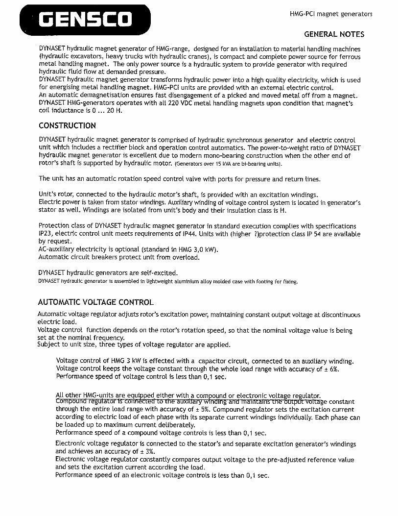
Automatic frequency control valve is to keeprotation speed and (±5 % ) when incominghydraulic oil flow (Q) can vary from minimalup to value exceeding Qmtri by 10 - 30 1/mmdepending on generator size.VoLtage reguLator maintains the voltage constantat constant rotor’s rotation speed.
Qmfn Qnom + 1...5 1/mmQmin - minimal flowQnom - nominal flow
CLASS~F1CAT~ONDYNASET hydraulic generators are manufactured in conformity with the 98/37, 73/23, 89/336 CEE directivesand their amendments. They are also manufactured in compLiance with the following regulations: CEI 2-3,EN 60034-1, IEC 34-1, VDE 0530, BS4999-5000, CANICSA-C22.2, NF 51.100 and N°14-95 - W100-95.By request DYNASET hydraulic generators can be equipped with a radio interference protection to meetrequirements of specifications MIL STD 461 A/B and VDE 0875 cLass N.
DYNASET hydraulic magnet generator works being integrated into an originaL hydrauLicsystem of a material handling machine.
Unit can be placed deliberately ensuring an easy access to the unit. Generator shouLd
________ be positioned horisontatty. AdditionaLly, return Line must be connected to a hydrauLic oil
tank in the shortest possible way in order to keep return oiL pressure under 5 bar.Cooling capacity of hydraulic system, designed for continuous operation (an excavator),is generally sufficient under proper instalLation of HMG-generator. An additional oiL cooLeris required when HMG-unit is instaLLed to a truck with and hydrauLic hoist.Ensure that the filtration capacity of a hydrauLic system is sufficient.
To enable putting DYNASET generator into operation onLy pressure- (P) and return (T) Lines are to be connectedto the hydraulic system.Ensure that the hydraulic fluid flow is sufficient to run the unit, i.e. at Least the minimaL flow must be avaiLabLe.At the hydraulic flow Less that demanded nominal rate the generator wiLt not work properly at alL. If thehydraulic flow is so excessive, that the automatic speed controL valve is unable to handLe it, the unit beginsto hunt. In the latter case the hydraulic flow is to be reduced either by repLacing an existing hydraulic pumpwith a suitable one or using flow limiter. DYNASET PRIORITY VALVE is recommended.After having been connected to the hydraulic system, DYNASET hydrauLic magnet generator is to be startedby directing the hydraulic flow to the unit’s pressure port by means of controL vaLve - manual or solenoid. Evensimple ball valve or three-way valve can be used.To ensure DYNASET’s proper operation, the hydraulic pressure must be set at least to the LeveL, at which thenominal power output is achieved (ref. to PARAMETERS). Lower pressure reduces output power. Maximumhydraulic pressure is 250 bar (ref. to PARAMETERS). If the hydrauLic system main pressure is higher, servicepressure relief valve must be used.Ensure also that your machine’s hydraulic fluid cooling is working properly when DYNASET magnet generatoris in operation.DYNASET HYDRAULIC GENERATORS ARE DESIGNED FOR EASY INTEGRATION INTO HYDRAULIC SYSTEM OF ANY TYPE:
INSTALLATION
Qmm Q~ HYDRAULICmax FLUID FLOW
kii@
GENSCOL 1. OPEN CENTRE HYDRAULIC SYSTEM WITH VARIABLE DISPLACEMENT PUMP
HMG-PCI magnet generators
INSTALLATION
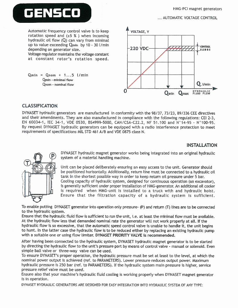
The demanded hydraulic flow is to be ensured and controlled with a DYNASET PRESSURE COMPENSATED PRIORITY VALVE.
DYNASET PV SAE 3/4 - 1114 -XX (pm - 12/24 Vpriority valve includes following components:
ISandwich-mounted pressurecompensator with SAE-flangespecification;2.Solenoid valve I 2/24V;3.Flow Limiter;4.Pressure relief valve.
PV SAE priority valve is designed forthe installation to main pressure Linebetween SAE-f(anges of main hydraulicpump. Pre-adjusted, independent fromother functions and priorised hydraulicflow for DYNASET-unit comes from thesolenoid valve.
The rest of hydraulic pump’s capacity is available for all otherfunctions. Furthermore, pump’s control works together withDYNASET PV SAE priority valve.
ALSO AVAILABLE for open centre hydraulic systems with variable displacement pump: PRIORITY VALVE PV C3C ¾ - 1 ¼ - 12/24 V.
DYNASET PRIORITY VALVES enable to operate your DYNASET-unit simuLtaneously with other hydraulicexecutors.
( 2. CLOSED CENTRE HYDRAULIC SYSTEM WITH VARIABLE DISPLACEMENT PUMP
The demanded hydraulic flow is to be ensured and controlled with a DYNASET PRESSURECOMPENSATED LOAD SENSING (LS) VALVE.
DYNASET LS-valve includes followingcomponents:1.Flow limiter;2.Solenoid valve I 2/24V;3.Pressure relief valve;4.Shuttle valve OPTIONAL).
DYNASET LOAD SENSING VALVES:LSV4O, 60, LSV 95 jaLSV 1501.5-connection, pressure relief, max. hydraulic flow40, 60, 95 ja 150 I/mm respectively.
DYNASET FLOW LIMITERS to the pressure line:VR 40 PK - 1/2, max. 35 1/mm, with pressure compensation;VR 95 PI( - 3/4, max. 95 1/mm, with pressure compensation.
ALSO AVAILABLE for closed centre hydraulic systems with variable displacement pump:DYNASET SOLENOID VALVE to the pressure Line for remote starting.
SV 70 NC - 1/2 - 12/ 24 V max 70 1/mm with LS -connection;SV 150 NC— I - 12/24 V max 150 I/mm with LS -connection.
r~
r—- ___
- B 1 ~ -
‘-I
I •~ IS LSI
I CF
‘4—‘
J~J_~9j

GENSCO HMG-PCI magnet generators
INSTALLATION
( I. HYDRAULIC SYSTEM WITH CONSTANT DISPLACEMENT PUMP
The demanded oil flow is to be ensured with proper hydraulic pumpchoice. In systems with redundant hydrauLic flow an installation withDYNASET PRIORITY VALVE is recommended.
InstaLlation with a standard pressurecompensated 3-way valve should be avoided inorder to cLose off potentiaL waving in hydrauLicsystem.
ALSO AVAILABLE for hydraulic systems with constantdisplacement pump:DYNASET FREE-CIRCULATION VALVE with soLenoidand pressure control, type VKV 90—3/4.
ELECTRIC INSTALLATION KITS TO HMG MAGNET GENERATORS
Having fitted mechanically a generator to your carrier, acomplish an electric connection.Along with DYNASET 11MG-generator following wiring kits can be purchased:I. MAGNET WIRING KIT2. 11MG CONTROL WIRING KIT
C’~ MAGNET WIRING KIT
Magnet’s cable 5mn with p(ug.1.2Socket with a protective cover,to be fitted to a stub boom.
1.3Cable 20 m from beam’s socketto a generator’s socket, withplug.
SI
__f~~~~:=:~7 I
I LoooooooooQc~ooooooooJ I
-
i~iI.
5 K 16A5 x 1645 K 16A5x 32A5 x 3245x63A (5 x 634
011MG 311MG 6kW11MG 10kW11MG 12kw11MG 15 kW11MG 20 kW11MG 30kW
11MG 3I~N 5 x 2,5mm~11MG 6kW 5 K 2,5mmHMG1OkW 5 x 2,5mm~11MG 12kw 5 x 6,0mm11MG 15 kW 5 x 6,0mm211MG 20 kW S x 6,0mm211MG 30kW 5 x 6.0 mm2
7 SM)
ICAELE ZOM11MG 3kW5x2,5mm~11MG 6kW5x2,SmmHMG1OkW 5 x 2,5mm2HUG 12kw s x 6,0 mm2HUG 15 kW 5 x 6,0mm211MG 20 kW 5 x 6,0 mm2
QIMG 30 kW 5 x 6,0 mm~J
SOCKET AND PLUG
HMG 3kW 5xl6AHMG 6kW 5x16AHMG1OkW 5xl6AHMG12kW 5x32AHMG1SkW 5x32AHMG2OICW Sx63AHMG3OkW 5x63A
LEDKI RED
rnLED 1(2 YELLOW —..‘ ~ ____) I
~KZ
LED 1(3 GREEN1(3
GENSCO HMG-PCI magnet generators
__________________________ OPERATION
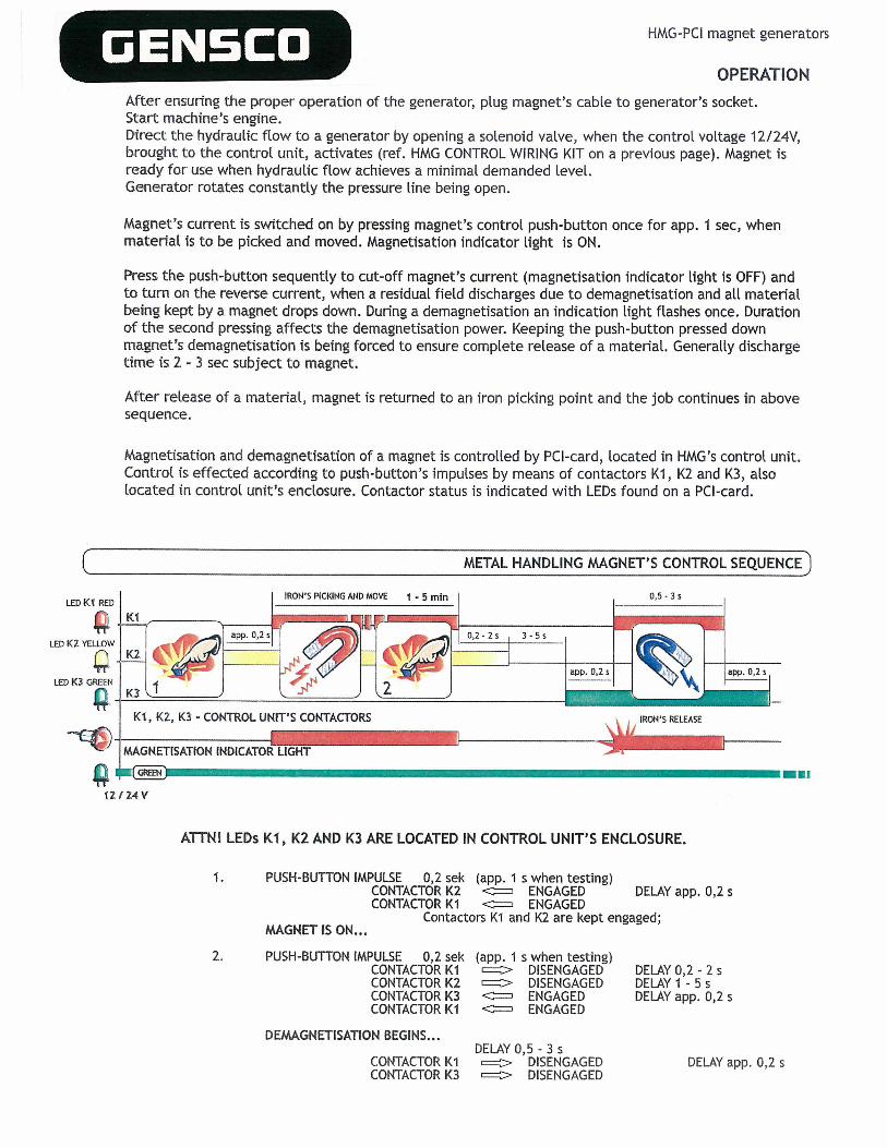
After ensuri rig the proper operation of the generator, plug magnet’s cabLe to generator’s socket.Start machine’s engine.Direct the hydraulic flow to a generator by opening a soLenoid vaLve, when the control voltage I 2/24V,brought to the control unit, activates (ref. HMG CONTROL WIRING KIT on a previous page). Magnet isready for use when hydraulic flow achieves a minimal demanded leveL.Generator rotates constantly the pressure Line being open.
Magnet’s current is switched on by pressing magnet’s controL push-button once for app. I sec, whenmaterial is to be picked and moved. Magnetisation indicator Light is ON.
Press the push-button sequently to cut-off magnet’s current (magnetisation indicator light is OFF) andto turn on the reverse current, when a residuaL fieLd discharges due to demagnetisation and all materiaLbeing kept by a magnet drops down. During a demagnetisation an indication light fLashes once. Durationof the second pressing affects the demagnetisation power. Keeping the push-button pressed downmagnet’s demagnetisation is being forced to ensure compLete reLease of a material. GeneraLly dischargetime is 2 - 3 sec subject to magnet.
After release of a material, magnet is returned to an iron picking point and the job continues in abovesequence.
Magnetisation and demagnetisation of a magnet is controLled by PCI-card, Located in HMG’s control unit.Control is effected according to push-button’s impulses by means of contactors KI, K2 and K3, alsolocated in control unit’s enclosure. Contactor status is indicated with LEDs found on a PCI-card.
METAL HANDLING MAGNET’S CONTROL SEQUENCED
IRoN’S PICKING AND MOVE I - 5 mm 0,5-3
0,2-2s 3-5s
I
IRON’S RELEASE
app. (1,2
21(1, KZ, K3 - CONTROL UNIT’S CONTACTORS
MAGNETISAT1ON INDIcATOR LIGHT_II
12 (24 V
ATTNI LEDs KI, K2 AND K3 ARE LOCATED IN CONTROL UNIT’S ENCLOSURE.
1. PUSH-BUTTON IMPULSE 0,2 sek (app. 1 s when testing)CONTACTOR K2 ‘cDz ENGAGED DELAY app. 0,2 sCONTACTORKI ~ ENGAGED
Contactors KI and K2 are kept engaged;MAGNET IS ON...
PUSH-BUTTON IMPULSE 0,2 sek (app. 1 s when testing)CONTACTOR KI ~ DISENGAGED DELAY 0,2 - 2 sCONTACTOR K2 c~> DISENGAGED DELAY I - 5 sCONTACTOR K3 ‘~ ENGAGED DELAY app. 0,2 sCONTACTORKI ~ ENGAGED
DEMAGNETISATION BEGINS,..DELAYO,5 -3s~ DISENGAGED=~“ DISENGAGED
CONTACTOR KICONTACTOR K3
DELAY app. 0,2 s

GENSCOHydraulic pressure is being adjusted according to the magnet’s power demand, when the hydraulic fLuid flowis being kept constant.
DYNASET hydraulic magnet generator produces highquality electric power within pressure range fromidle run pressure to the maximum aLlowed value.The nominal power output is achieved at pressurevalue, which is noticeably less than the maximumaLlowed operation pressure.Refer to the attached diagram and technicaLspecifications.
ATTN I
HMG-PCI magnet generators
OPERATION
A
P (kWkW
MAINTENANCE
HMG generator is equipped with an overLoad circuit breaker as weLl as with a temperature switch. At overloadthe circuit breaker switches off magnet’s current without demagnetisation. However, the iron comes off fora tong white causing dangerous situation. NEVER STEP TO THE AREA UNDER LOADED MAGNET! Having rectifieda probLem, reset the circuit breaker with its pushbutton or switch.Temperature switch cuts off magnet’s current without demagnetisation when control unit’s temperatureexceeds maximum aLlowed vaLue. Generator can be Left running in order to coot it as fast as possible. Theunit being cooled enough, temperature switch turns on the magnet’s current automatically, when an operatorcan proceed with his job.ATTN!Magnet’s Load duty is 60%. Exceeding of ED-vaLue causes magnet’s overheating
DYNASET hydraulic generators are tow-maintenance units. Only normaLly wearing parts such as seatings inhydraulics, brush coLlector and bearings shouLd be repLaced when necessary.Refer also to the TROUBLESHOOTING section.ATTN.!Capacitors in control unit keep the charge for a Long time after stopping a generator.Prior to commence any service:
* stop both magnet generator and the carrier* wait at least 10 minutes* ensure with a gauge that capacitors have no charge.
ATTN.!
CLEANLINESS OF YOUR HMG-UNIT MUST BEMAINTAINED ON A REGULAR BASIS. CHECKYOUR EQUIPMENT AFTER EVERY WORKINGSHIFT AND DEPENDING ON AN OPERATIONALENVIRONMENT CLEAN A GENERATOR ASFREQUENTLY AS NECESSARY TO KEEP IT INPERFECT WORKING CONDITION.
Remove side screens (1) and air diffuser (3) to clean fancompartment as welL as rotor and stator.
Use blow gun with a REASONABLE Remove cover (2) to dust alternator’s electric components.Having dusted/cleaned the generator, repLace screens/coversDELIBERATION to dust your equipment. and secure them with appropriate screws.(Above picture for reference only - refer to the data pages
of specific HMG-modeL).
Pressure p, bar
Q (L/mtn) const
~I~8I
I~j
GENECO HMG-PCI magnet generators
MAINTENANCE
HYDRAULIC FLUIDS
SAFETY
WARRANTY
Remove all oil deposits. Remove all unnecessary grease and oil from the unit. Accumulated greaseand oil can cause overheating and subsequent generator damage and may present a potential firehazard. Do not leave in the generator case or control box anything which does not belong to the assembly.
The tightness of lids and covers as well as of all screw joints must be inspected on a regular basis, for instanceat least once a week or more frequently, if a generator is exposed to a noticeable vibration.
Having carried a maintenance or cleaning, NEVER LEAVE ALTERNATOR’S COVER AND/OR ELECTRIC BOX’ COVERUNREPLACED AND UNSECURED! Condition of any seal/gasket must be inspected and defective parts replaced.
Wide range of standard hydraulic fluids can be used with the DYNASET hydraulic equipment.Subject to the operating temperature, following mineral hydraulic oils are recommended:
ISO VG 325 for oil’s operation temperature up to 70 °C;ISO VG 46S for oil’s operation temperature up to 80 ~C;ISO VG 685 for oil’s operation temperature up to 90 °C.
Synthetic and bio~oils can be used as welt if their viscosity characteristics and lubricating efficiency arecorresponding to above mineral oils. Automatic transmission fluids and even engine oils can be used, providedthat they are allowed to be used in hydraulic system of your carrier machine.Prior to use special hydraulic fluids a with DYNASET equipment, please be kindly requested to contact nearestDYNASET representative for an advice.
The generator’s output voltage is as high as 230/400 V. Operators and maintenance personnel must alwayscomply with local safety regulations and precautions in order to close out the possibility of damages andaccidents. Prior to detaching a magnet from a carrier, unplug it from a generator’s socket I Capacitors ofcontrol unit can discharge developing voltage over 200V even the equipment stands still.
The hydraulic system is usually pressurised up to 250 (420) bar. Follow all your local safety instructions relatedto the high pressure hydraulics.TECHNICAL CONDITION OF YOUR MACHINERY AND EQUIPMENT MUST BE SUBJECTED TO CONSTANT SURVEILLANCE.Hydraulic system of a carrier machine should be maintained according to the service program. All couplings,valves and hoses of the system should be leak-proof and kept clean in order to follow their technical condition.Hydraulic leakages must be rectified immediately to avoid injuries caused by hot oil blowouts.
Prior to maintenance, detaching from a carrier or disassembling a DYNASET-unit, the hydraulic system of amachine should be stopped and DYNASET’s hydraulic circuit depressurised.
When working with a DYNASET hydraulic equipment, appropriate protective clothing, safety goggles and glovesshould be worn. Do not touch parts heated by hydraulic oil.
WHEN CARRYING OUT ANY SERVICE DISASSEMBLING OR REPAIR OF DYNASET HYDRAULIC UNIT (AND/ORHYDRAULIC SYSTEM OF A CARRIER MACHINE), ABSOLUTE CLEANLINESS MUST BE MAINTAINED TO ENSURERELIABLE AND TROUBLE-FREE OPERATION OF YOUR EQUIPMENT.
All installation and service of both hydraulic and electric equipment must be performed by qualified andexperienced personnel only.
DYNASET products are warranted against defects in materials and workmanship for a period of 6 (six) monthsfrom the date of purchase. Exceptions are parts subject to normal wear and tear, such as seals and other partsthat become worn through normal use of the unit.Warranty covers detective parts solely. Expenditure incidental to shipping and replacement are not coveredby present warranty.The warranty is void if product has been modified, provided with parts other than original or misused.

1.2220 VDC voltage does not come from thecontrol unit to magnet’s terminals.
1.2Contactor’s KI breaker points are worn. Check their resistancewhen the contactor is engaged. Correct value is 0,2 Ohm.
Rectifier’s diode bridges (HMG3 kW) or diodes (HMG6 -...)
short-circuited or blown. Check diode bridges / diodes.Proceed as follows (ref. to electric diagram)+ diodes: K1/LI - 1<2/Li; Ki/L2 - 1<2/Li; KI/L3 - K2/L1.
— diodes: Ki/Li - K21L3; K1/L2 - K21L3; K1/L3 - K2/L3.ATTN I When checking diodes, generator must be stopped.Measuring procedure does not require detaching diodes froma control unit. Replace damaged components.
Magnet’s cable damaged.
1.3AC-voltage does not come from generatorto the control unit.
1.4Malfunction in contactor’ KI and K2control. The contactors must be engaged.
1.3Check whether there is a 3-phase voltage 150- 180 VAC onterminals TI, T2 and T3 of contactor 1<1.Potential malfunction in hydraulic system.Potential failure in AC-generator’s windings, brush gear,excitation rectifier or voltage regulator.Ref. to the attached troubleshooting for AC-generator.
1.4Check control wiring, especially magnet’s push-button andgenerator’s starting switch.Check the PCI-card, replace the fuse if blown.Test contactor’ operation: press the magnet’s control pushbutton and follow LED5 sequence (ref. to the item OPERATION).Replace the PCI-card if damaged.Ref. also to the attached instructions for PCI-card.
1.5Check resistance of breaker points when the contactor isengaged. Correct value is 0,2 Ohm.
1.6Check coil’s resistance and compare the result to the valueindicated in the table thereinafter. Check also coil’s inductanceif possible.
DEN5CO~ HMG-PCI magnet generators
TROUBLESHOOTING
I. AC-hydraulic generator 230V/50 Hz,RPM-regulator;
2. Control unit, reCtifier PCI-Card, ContaCtors3. Ferrous metal handling magnet
1~MAGNET DOES NOTWORK
1.11.1Magnet unplugged or magnet’s cabledamaged.Red failure indication LED on PCI-card isON.
Replug the magnet; change the cable if damaged.
1.5Contactor’s K2 breaker points are worn.
1.6Magnet’s coil is damaged.

GENSCO HMG-PCI magnet generators
TROUBLESHOOTLNG
2.1Test contactor’ operation: press the magnet’s control pushbutton and follow LEDs sequence (ref. to the itemOPERATION). Replace the PCI-card if damaged.Ref. also to the attached instructions for PCI-card.
2.2Check resistance of breaker points when the contactor isengaged. Correct vaLue is 0,2 Ohm.
3.1.1Magnet’s power demand exceeds HMG’s output. Generatorgets overloaded and stopped by an automatic circuit breaker.Choose magnet according to HMG’s power output.
3.1.2Magnet’s cable’s short-circuit. Automatic circuit breakerstops the generator.Unplug the magnet; if circuit breaker does not trip shortlyafter starting the generator, cable is damaged.
3.1.3Control unit overheated.Control units thermostat switch tripped by reason of Lresistor’s failure.Insufficient cooling.
3.2Magnet’s voltage too low:Does DC-voltage come to magnet’s terminals?Does AC-voltage comes to the control unit?
Check AC-generator according the attached instructions;Check actuating hydraulics.
3.3Generator’s output voltage too high causing overloading.Check AC-generator according the attached instructions;Check actuating hydraulics.Adjust the output voltage to proper level.ATTN I High voltage is hazardous to a generator. Rectifya malfunction immediately.
2. 2.1LRON DOES NOT GET Contactor’s KI and K3 do not operate inRELEASED FROM A correct sequense.MAGNET(DEMAGNETISATION DOESNOT WORK)
2.2Contactor’s K3 breaker points are worn.
3.13.MAGNET Magnet keeps working only a short time.MALFUNCTIONS.
3.2Low magnet’s power.
3-3Magnet’s power consumption excessive,automatic circuit breaker stops thegenerator.
DENECO HMG-PCI magnet generators
TROUBLESHOOTiNG
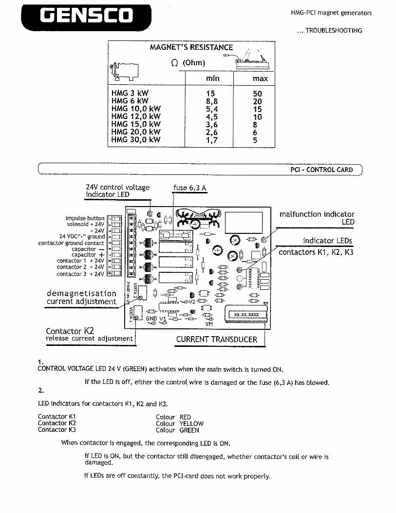
MAGNET’S RESISTANCE
~ Q(Ohm)~ mm max
HMG3kW 15 50HMG6kW 8,8 20HMGIO,OkW 5,4 15HMGI2,OkW 4,5 10HMGI5,OkW 3,6 8HMG2O,OkW 2,6 6HMG3O,OkW 1,7 5
demagnetisationcurrent adjustment
Contactor K2release current adjustment
PCI - CONTROL CARD
1.CONTROL VOLTAGE LED 24 V (GREEN) activates when the main switch is turned ON.
2.If the LED is off, either the control wire is damaged or the fuse (6,3 A) has btowed.
LED indicators for contactors Ki, K2 and K3.
Contactor KIContactor K2Contactor K3
Colour REDColour YELLOWColour GREEN
When contactor is engaged, the corresponding LED is ON.
If LED is ON, but the contactor stilt disengaged, whether contactor’s coil or wire isdamaged.
24V control voltageindicator LED
impulse buttonsolenoid + 24V
+ 24V24 VDC”-” ground
contactor ground contactcapacitor —
capacitor +contactor I ÷ 24Vcoritactor 2 ÷ 24Vcontactor 3 + 24V
~E1E~
o.’ci
malfunction indicatorLED
contactors Ki, K2, K3
If LEDs are off constantly, the PCI~card does not work properly.

GENECO [1MG-PCI magnet generators
TROUBLESHOOTING
PCI - CONTROL CARD 3
Colour RED
3.
MALFUNCTION INDICATOR LED
The concerned LED indicates control voltage failure and malfunction of magnet current meteringcircuit.If LED is continuously ON when working:
3.1 Magnet cable is disconnected or damaged.3.2 Current metering circuit of PCI-card damaged or the PCI-card is not adjusted
property (check the set value of potentiometers VIRTAI and VIRTA2).3.3 If ted keeps flashing after working cycLe, the wire of 24V has poor contact.
The LED starts flashing when 24V voltage cuts off for longer time than 0,2 s.
SAFE MODE
PCI CONTROL CARD runs in safe mode when a failure occurs. MALFUNCTION INDICATOR LEDis ON continuously, but the job can be continued without immediate tracing and rectifying the failure.tn SAFE MODE fixed demagnesation time is 6 sec, however magnet’s considerable inductance mayextend the above time with I - 3 seconds.
The PCI card runs in SAFE MODE when the HMG-generator is ON, but the magnet cable is disconnected.
ADJUSTING THE INDUCTION CURRENT ON MAGNET TO DISENGAGE CONTACTOR K2POTENTIOMETER VIRTAI
PCI-card measures automatically the inductive current and disengages the contactorK2 at the right time without arcing, regardless of magnet inductance (0 - 20 H) andpower.
Adjusted induction current value can gauged with mV-meter (1 mV = 0,001 V)between measure points VI- and GND of the card, when the control voltage 24Vis ON.On condition that I A = 40 mV and factory default of 300 mV, current valuemakes 7,5 A.
To speed up the opening time of contactor K2, Vi -value can be increased to 330 mV(= 8,3A) by setting the potentiometer VIRTAI counter-clockwise (max. I rev. 30 mV.DO NOT increase too much because that reduces the service life of contactor K2.
ADJUSTING THE DEMAGNESATION CURRENTPOTENTIOMETER VIRTA2
Adjusted demagnetising current value can be gauged with mV-meter between measurepoints V2- and GND of the card, when the control voltage 24V is ON.
Factory default is -100 mV (= 2,5 A). Demagnetising can be increased upto -130 mV (=3,25 A)by setting the potentiometer VIRTA2 clockwise (I round = 30 mA).
GAUGING THE MAGNET’S CURRENT
When the magnet is connected and energised, the current can be gauged between measurepoints VM- and GND of the card.Factory default scale is 1A = 40 mV (i.e. magnet current of IOA is gauged as 400 mV).
GENSCO HMG-PCI magnet generators
TROUBLESHOOTING
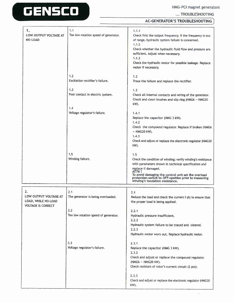
AC-GENERATOR’S TROUBLESHOOTi~]
1.1.1Check first the output frequency. If the frequency is outof range, hydraulic system failure is concerned.1.1.2Check whether the hydraulic fluid flow and pressure aresufficient. Adjust when necessary.1.1.3Check the hydraulic motor for possibLe Leakage. Replacemotor If necessary.
1.2Trace the failure and replace the rectifier.
1.3Check all internal contacts and wiring of the generator.Check and clean brushes and slip ring (HMG6 — HMG2OkW).
1.4.1Replace the capacitor (HMG 3 kW).1.4.2Check the compound regulator. Replace if broken (HMG6— HMG2O kW).1.4.3Check and adjust or replace the eLectronic regulator (HMG3OkW).
1.5Check the condition of winding; verify winding’s resistancewith parameters shown in technical specification andreplace if damaged.AflN ITo avoid damaging the control unit set the overloadprotection switch to OFF-opsition prior to measuringwinding’s Insulation resistance.
2.1Reduce the Load and check the current I (A) to ensure thatthe proper Load is being appLied.
2.2.1Hydraulic pressure insufficient.2.2.2Hydraulic system failure to be traced and cleared.2.2.3Hydraulic motor worn out. RepLace hydrauLic motor.
2.3.1Replace the capacitor (HMG 3 kW).2.3.2Check and adjust or replace the compound regulator.(HMG6 — HMG2O kW).Check resistors of rotor’s current circuit (2 pcs).
2.3.3Check and adjust or repLace the eLectronic regulator (HMG3OkW).
1. 1.1LOW OUTPUT VOLTAGE AT Too tow rotation speed of generator.NO LOAD
1.2Excitation rectifier’s failure.
1.3Poor contact in eLectric system.
1.4VoLtage regulator’s failure.
1.5Winding failure.
2. 2.1LOW OUTPUT VOLTAGE AT The generator is being overloaded.LOAD, WHILE NO-LOADVOLTAGE IS CORRECT
2.2Too low rotation speed of generator.
2.3Voltage regulator’s failure.

GENSCOHMG-PCI magnet generators
TROUBLESHOOTING
AC-GENERATOR’S TROUBLESHOOTi~J
3.1Trace the failure and replace the rectifier.
3.2.1Replace the capacitor (f-IMG3 kW).3.2.2Check and adjust or replace the compound regulator (HMG6—HMG2O kW).3.2.3Check and adjust or replace the electronic regulator ([IMG3OkW).
3.3Verify the winding resistance with parameters shown intechnical specification and replace if damaged.
3.4Check all internal contacts and wiring of the generator.Check and clean brushes and slip ring(HMG6 — HMG2O kW).
3.5Use external battery of 12 V for 1 - 2 sec to magnetise therotor.
4.1.1Check generator’s hydraulics, including automatic frequencycontrol valve. Make an adjustment, replace RPM-cartridgeif necessary.4.1.2Check whether the hydraulic fluid flow and pressure areexcessive. Adjust when necessary.4.1.3Check the hydraulic motor for possible leakage. Replacemotor if necessary.
4.2Adjust stability of the regulator.Replace if broken.
4.3Check all internal contacts and wiring of the generator.Check and clean brushes and slip ring (HMG6 — HMG2O kW).
3. 3.1EXCITATION FAILURE Rectifier’s failure.
3.2Voltage regulator’s failure.
3.3Winding failure.
3.4Poor contact in electric system.
3.5Insufficient residual magnetism.
4. 4.1OUTPUT VOLTAGE Instable rotation speed of generator.INSTABILITY
4.2Electronic voltage regulator’s failure(HMG3O kW).
4.3Poor contact in electric system.
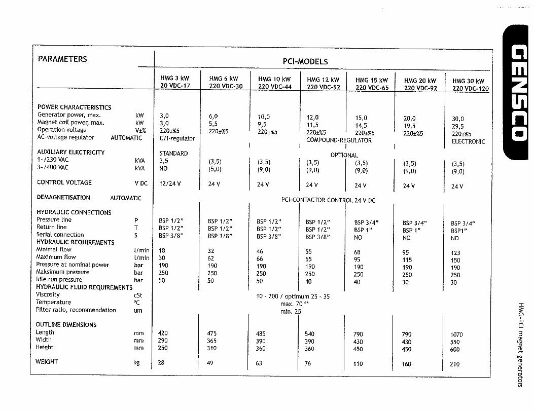
PARAMETERS PCI-MODELS
HMG 3 kW 11MG 6 kW 11MG 10 kW 11MG 12 kW 11MG 15 kW 11MG 20 kW 11MG 30 kW20 VDC-17 220 VDC-30 220 VDC-44 220 VDC-52 220 VDC-65 220 VDC-92 220 VDC-120
POWER CHARACTERISTICSGenerator power, max.Magnet coil power, max.Operation voltageAC~voltage regulator
AUXILIARY ELECTRICITY1-1230 VAC3-/400 VAC
CONTROL VOLTAGE
DEMAGNETISATION
12,0 15,011,5 14,5220±%5 220±%5COMPOUND-REGULATOR
(3,5)(9,0)
24 V
OPTIONAL(3,5)(9,0)
24 V
10,09,5220±%5
(3,5)(9,0)
24 V
BSP 1/2”BSP 1/2”I3SP 3/8”
466619025050
kWkW
AUTOMATIC
tWAkVA
V DC
AUTOMATIC
pTS
1/mmI/mmbarbarbar
cSt
urn
mmmmmm
kg
PCI-CONTACTOR CONTROL 24 V DC
3,03,0220±%5C/I-regulator
STANDARD3,5NO
12/24 V
BSP 1/2”BSP 1/2”BSP 3/8”
183019025050
420290250
28
6,05,5220±%5
(3,5)(5,0)
24 V
BSP 1/2”BSP 1/2”BSP 3/8”
326219025050
475365310
49
HYDRAULIC CONNECTIONSPressure lineReturn lineSerial connectionHYDRAULIC REQUIREMENTSMinimal flowMaximum flowPressure at nominal powerMaksimum pressureIdle run pressureHYDRAULIC FLUID REQUIREMENTSViscosityTemperatureFilter ratio, recommendation
OUTLINE DIMENSIONSLengthWidthHeight
WEIGHT
BSP 1/2”I3SP 1/2”BSP 3/8”
556519025040
20,019,5220±%5
(3,5)(9,0)
24 V
BSP 3/4”BSP 1”NO
9511519025030
790430450
160
30,029,5220±%5ELECTRONIC
(3,5)(9,0)
24 V
BSP 3/4”BSP1”NO
12315019025030
1070550600
210
10 - 200 I optimum 25 - 35max. 70 **
mm. 25
BSP 3/4”BSP 1”NO
689519025040
790430450
110
485390360
63
540390360
76
n3
(SQ
(D
(10
(D0’
0

GENECOHMG-PCI magnet generators
TROUBLESHOOTING
5.4
5.5
AC-GENERATOR’S TROUBLESHOOTING]
Can it be fixed?
6. 6.1 6.1OIL LEMCAGES Failure of axial seating of generator’s AxiaL sealing of hydraulic motor broken
hydraulic motor. External indication— by reason of EXCESSIVE PRESSURE IN RETURN LINE.ydraulic oil outflow from ventilation grids. Rebuild the return line. Maximum allowed pressure in return
Line is 5 bar.Replace axial sealing of generator’s motor.
6.2 6.2Oil leakage from hydraulic motor. Hydraulic motor worn out and should be replaced.
5.ABNORMAL NOISE LEVEL
5.1Bearing failure.
5.2Generator is being overloaded.
5.3Short circuit in powered unit.
Foreign items in generator’s casing.
5.1Replace broken bearing.
5.2Reduce the load to proper level.
5.3Check powered unit. Rectify a defect.
5.4Stop generator and hydraulic system. Remove foreign itemfrom unit.
5.5Extremely fluctuating Load.
GENSCO
00In
851
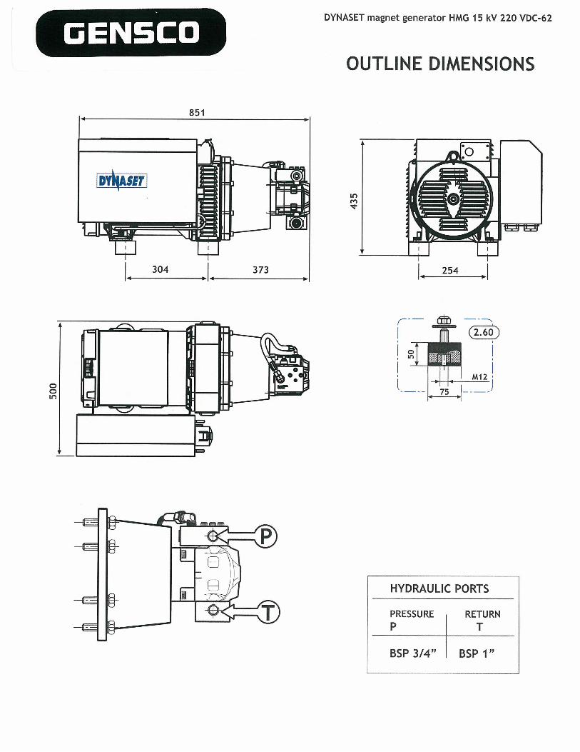
DYNASET magnet generator HMG 15 kV 220 VDC-62
OUTLINE DIMENSIONS
In
HYDRAULIC PORTS
PRESSURE RETURNP T
BSP 3/4” BSP 1”
I~
304 373 254

N
a]iVDIaNI ]~ G1flOHS N]~WflN1VINJS aNy iJGOW ‘]dAd. SJJNfl‘SJ~JVd ]~iVdS 9NIN]G~JO N]HM
I JION
SINYd 3NYdS
OJGNJDz9oaA ozz M S ~ 9WH Jow.ieue~ ~U~EW 1]SVNA~
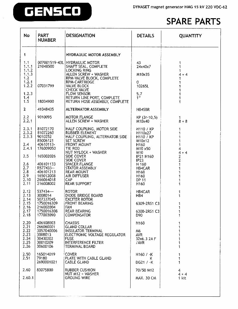
GENECODYNASET magnet generator HMG 15 kV 220 VDC-62
SPARE PARTSNo PART DESIGNATION DETAILS QUANTITY
NUMBER
I HYDRAULIC MOTOR ASSEMBLY
1.1 007001519-43L HYDRAULIC MOTOR 43 11.1.1 21048500 SHAFT SEAL, COMPLETE 24x40x7 11.1.2 LOCKING RING 11.1.3 ALLEN SCREW + WASHER M10x35 4 ÷ 41.2 RPM-VALVE BLOCK, COMPLETE 11.2.1 RPM-CARTRIDGE 0 11.2.2 07031799 VALVE BLOCK 10265L 1
CHECK VALVE 11.2.3 FLOW SENSOR 5.7 11.4 RETURN LINE PORT, COMPLETE 1” 11.5 18034900 RETURN HOSE ASSEMBLY, COMPLETE 1
2 41048435 ALTERNATOR ASSEMBLY HB4SBR
2.2 9010095 MOTOR FLANGE KP (3r-10,5) 12.2.1 ALLEN SCREW + WASHER M10x40 8 + 8
2.3.1 81072170 HALF COUPLING, MOTOR SIDE H110 I KP 12.3.2 81072260 RUBBER ELEMENT H110x27 12.3.3 9010252 HALF COUPLING, ALTERNATOR SIDE H110 / KP 1
85006121 SETSCREW M10x12 12.4 40610113- FRONTMOUNT H160 12.4.1 176009050 TIE ROD M10x50 4
NUT NYLOCK+WASHER M10 4÷42.5 165002026 SIDE COVER 1P21 H160 2
SIDE COVER IP23 22.6 406101133 SPACERFLANGE H160 12.7 R577433-- STATOR ASSEMBLY HB4CAR 12.8 406101213 REAR MOUNT H160 12.9 165012008 AIR DIFFUSER H160 12.10 266064018 CAP DP11 12.11 216008002 REAR SUPPORT H160 I
2.12 537434--- ROTOR HB4CAR 12.13 3008014 DIODE BRIDGE BOARD HB4 12.14 507337045 EXCITER ROTOR2.15 1750016309 FRONT BEARING 6309-2RS1 C3 12.16 216002004 FAN 12.17 1750016308 REAR BEARING 6308-2RS1 C3 12.18 177003090 COMPENSATOR D90 1
2.20 406108003 CHASSIS H160 12.21 266060001 GLAND COLLAR 12.22 3057040006 INSULATOR TERMINAL M6 12.23 3008013 ELECTRONIC VOLTAGE REGULATOR AVR 12.24 30430202 FUSE 32x6.3 2A F 12.25 30010209 INTERFERENCE FILTER /AVR 12.26 30600106 TERMINAL BOARD 1
2.50 165014019 COVER H160 I -K 12.51 79180 PLATE WITH CABLE GLAND K 1
2690001021 CABLE GLAND DG21 I -K I
2.60 83075800 RUBBER CUSHION 70150M12 4NUTM12+WASHER 4÷4
2.60.1 GROUNG WIRE MAX. 30 CM 1 kit

GENSCO
to
zLLIw‘3
DYNASET magnet generator HMG 15 kW 220 VDC-62
AVR ELECTRIC CONNECTIONS
WIRING DIAGRAM4-10 5-11 6-12W2 U2 V2C
?ii~1~LI (U) L2 (V) SENSING L3 (W)
,Ij\(V/2)
3L3 (W) L2 (V)
RESISTANCE CHARACTERISTICS
STATOR AUXILIARY ROTOR EXCITER STATOR EXCITER ROTOR
~ (ohm)
0,50 5,30 15,70 13 4
pEMCFilter1.
\~ ., z~—’,- .—I---
)( •—::=~
/ \ ~::~—~
Li (U)
4
9
.LINfl 1ONINOD
4-’
Z9-DCA CU M~I S I. DWH iowiaua~ ~U~W .L]SVNAa
D
(~oz~)
_iI~1~’_
. ______•~_~J\
00
OJSN]O

~~~1
>0I rr
r~riLi~LJ
<I,00r-z-l-~
m
T~U1__rfl~ ~
~-j
E 1,5 mm2 black
1,5 mm2 black
• 1,5 mm2 blue
1,5rnrn2yelllgreen
• 1,5 mni2 blue
C)P1z
~ii: L;t ~r~i~i’~a
[ 1~~ -l -1
2,5 mm2 black I2,5 mm2 black —~ — — T’
2.5 mm2 black _______________________ !‘~ !“ .P’F —) •.,, U, U,
3 3 3_____ 3 3 3
~a
Pr
, —-
III —
15mrn2bI~ck —r1,5 mm2 blue
1,5 mm2 black
1,5 mm2 black
~f~tiiii1r ~F
j -
!INfl 1ONINOD
z9-DaA OZZ M~I S I. DWH ~o~~aue~ ~9U~RW 1]SVNA~Ir OJEN3D

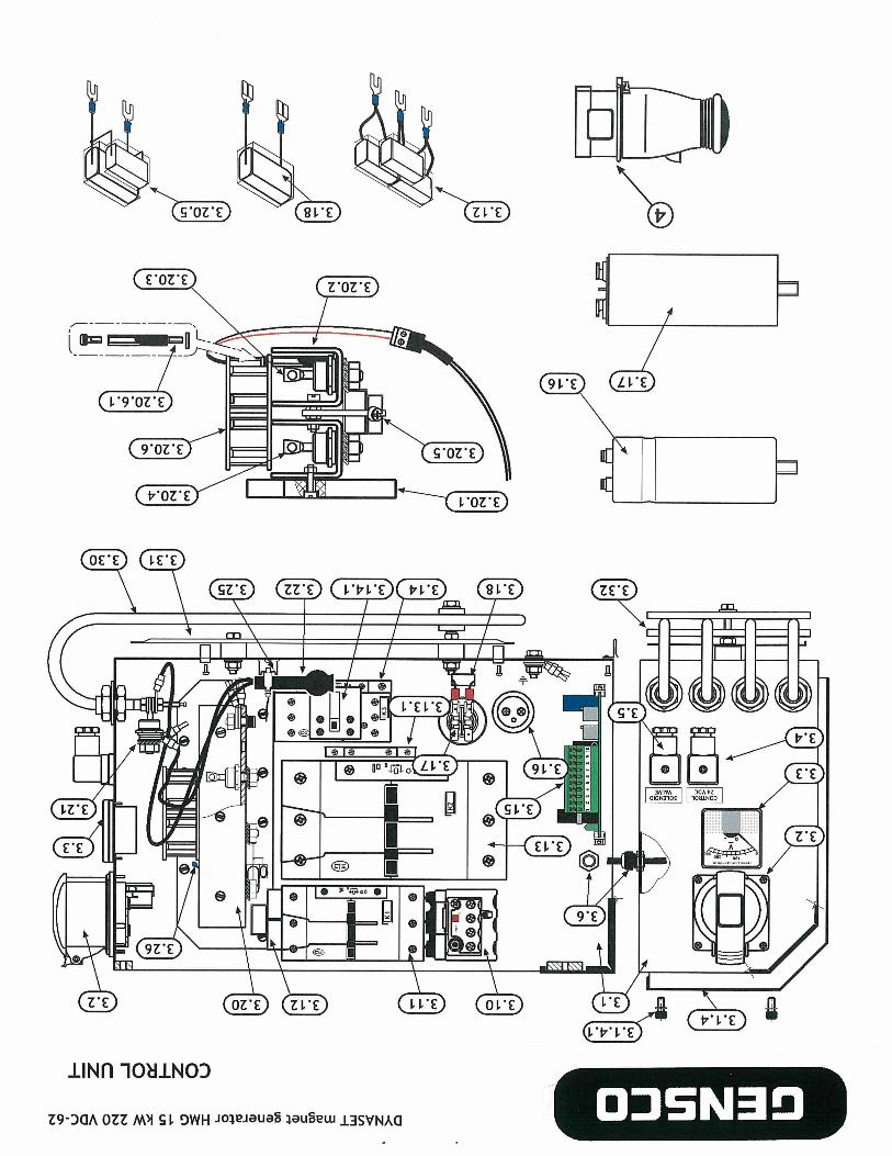
0ENSCO
No PART DESIGNATIONNUMBER
3 9010310 CONTROL UNIT
3.1 UNIT ENCLOSURE, COMPLETE3.1 .1 COMPONENT CHASSIS, COMPLETE
GASKET3.1.2 ASSEMBLY KIT3.1.2.1 9010266 HOLDER, FORE3.1.2.2 9010265 HOLDER, REAR
FASTENERS3.1.4 COVER3.1.4.1 ALLEN SCREW M6x10+WIDE WASHER +
+ GASKET
3.2 48058620 SOCKET 32A3.3 44051720 VOLTMETER3.4 48059610 CONTROL VOLTAGE CONNECTOR, COMPLETE3.5 48059610 SOLENOID VALVE CONNECTOR, COMPLETE3.6 CABLE GROMMET
3.10 44051600 THERMAL OVERLOAD RELAY3.11 4405143000 CONTACTOR
3.12 CAPACITOR UNIT3.13 4405146000 CONTACTOR3.13.1 44051490 AUXILIARY CONTACT3.14 44051380 CONTACTOR3.14.1 44051490 AUXILIARY CONTACT
3.15 9010318 PCI-CONTROLCARDINSTALLATION KIT
3.16 4605803000 CAPACITOR3.17 46057680 CAPACITOR3.18 46057580 CAPACITOR
3.20 RECTIFIER UNIT3.20.1 03001414 CHASSIS PLATE3.20.2 03001079 RECTIFIER / COOLER BAR3.20.3 46056510 DIODE -7OAUNF¼3.20.4 46056480 DIODE +70A UNF¼3.20.5 CAPACITOR UNIT3.20.6 46058430 FAN
FASTENERS
3.21 46056600 DIODE ÷ 85A UNF ¼
3.22 DIODE PROTECTION VARISTOR3.25 44051620 TEMPERATURE SWITCH3.26 44051650 TEMPERATURE SWITCH3.30 HMG-RESISTOR R163.31 03001880 HEAT REFLECTIVE SHIELD3.32 03001317 RESISTOR HOLDER
FASTENERS
3.XX WIRING KIT
4 PLUG 32A
DYNASET magnet generator HMG 15kW 220 VDC-62
CONTROL UNIT
DETAILS QUANTITY
15kW 1
HMG 12-20
HMG 15 1 kitHMG 15-20 1HMG 15-20 1
1 kitHMG 12-20 1
2+2+2
3P+N±E 1300 VDC 1Hirschmann 1Hirschmann 1
Z1-57 1K1 (DILM65) 1
lOOnFx3 1K2 (DILM8O) 1DILNO/NC1OA 1K3 (DILM32) 1DILNO/NC1OA 1
10000uF63V 120uF450V 1lOOnF 1
PE 1AL 27OHFR12O 370HF120 3220nF+68nF 124VDC 1
1 kit
85HF120 1
300 VAC (46056610) 190°C 1125°C 1l6Ohm 2HMG 12-20 1HMG 6-20 2
1 kit
NOT AVAILABLE 1 kit
3P+N+E 1