Embed Size (px)
Citation preview

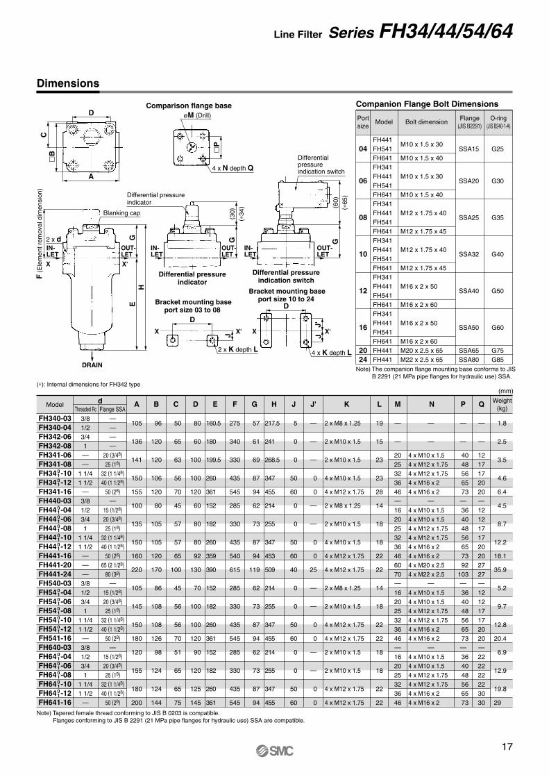
Hydraulic Filters
PageAccessory (Option)Element (µm)nominal filtrationPort size
Operating pressureSeries
1/2, 3/4, 1, 1 1/4, 1 1/2, 2, 2 1/2, 3, 3 1/2, 4
Vertical Suction Filter FHIA series
Micromesh 74, 105, 149
Differential pressure indicator Differential pressure indication switch Blanking cap
2
1/2, 3/4, 1, 1 1/4, 1 1/2, 2, 2 1/2, 3, 3 1/2, 4
Suction Filter with Case FH99 series
Micromesh 74, 105, 149
Differential pressure indicator Differential pressure indication switch Blanking cap
6
1/2, 3/4, 1, 1 1/4, 1 1/2, 2, 2 1/2, 3
Suction Guard FHG series
Micromesh 74, 105, 149
Differential pressure indicator Differential pressure indication switch Air breezer Cap
10
3/8, 1/2, 3/4, 1, 1 1/4 1 1/2, 2, 2 1/2, 3
Line Filter FH34/44/54/64 series
Paper 5, 10, 20
(Micromesh)
Differential pressure indicator Differential pressure indication switch Blanking cap
14
3/4, 1 1/4, 1 1/2Vertical Return Filter FHBA series
Paper 5, 10, 20
Micromesh 5, 10, 20
Differential pressure indicator Differential pressure indication switch Blanking cap
18
3/4, 1, 1 1/4, 1 1/2, 2 2 1/2, 3
Return Filter FH100 series
Paper 5, 10, 20
Micromesh 74, 105
Differential pressure indicator Differential pressure indication switch Blanking cap
21
1/4, 3/8, 1/2
Negative pressure
Negative pressure
Negative pressure
Max. 3.5, 7, 14, 21 MPa
Max. 1.6 MPa
Max. 1 MPa
Max. 1 MPa
Oil Filter FH150 series
Paper 5, 10, 20
(Micromesh)
Differential pressure indicator Differential pressure indication switch Blanking cap Bracket
25
——Magnetic Separator FHM series
— — 29
1

These vertical suction filters are designed for installation between the pump and reservoir tank. Their main function is to protect the pump.
No air pockets There are no places for air pockets to form. This prevents damage to the pump and enables normal operation to start immediately.
Elimination of all collected matter All collected matter can be disposed of reliably when the element is replaced. There is no dan-ger of collected matter dropping back into the tank.
No drain port required The structure of the filter does not contain areas for drain fluid to collect, so there is no need to manually drain the pump.
Easy element replacement Simply open the cover to quickly replace the element without touching the pipes. The ele-ment is extracted from the top, so no fluid can leak out.
Compact and lightweight The compact and lightweight design employs an aluminum casted housing.
Clogging sensor The sensor indicates when the element is be-coming dirty, facilitating maintenance and help-ing to avoid pump damage such as cavitations. Differential pressure indicator/two-stage indica-tor, reset type Differential pressure indication switch/visual combined, non-reset type
Fluid
Operating pressure
Operating temperature
Main material
Element
Differential pressure indicator operating pressure
Relief valve open pressure
Hydraulic fluid
Negative pressure
Max. 80°CAluminum cast
NBR or FKM Note)
NBR or EPDM Note)
Micromesh
74, 105, 149 µm (200, 150, 100 mesh)
0.15 MPa
20.0 kPa
26.7 kPa
Cover/Case
O-ring
Seal
Material
Nominal filtration
Differential pressure resistance
Specifications
FHIAl-04 FHIAl-06 FHIAl-08 FHIAl-10 FHIAl-12 FHIAl-16 FHIAl-20 FHIAl-24 FHIAl-28 FHIAl-32
1/2B
3/4B
1B
1 1/4B
1 1/2B
2B
2 1/2B
3B
3 1/2B
4B
30
50
95
150
220
350
550
770
1000
1300
Model Flange port size Note) Rated flow rate (l/min)
Model/Rated Flow Rate
CB-56H
CB-56H-V
CB-57H
CB-57H-V
AG-12H
AG-12H-W
AG-12H-V
Petroleum, Water-glycol, Emulsion
Phosphoric ester
Petroleum, Water-glycol, Emulsion
Phosphoric ester
Petroleum
Water-glycol, Emulsion
Phosphoric ester
Differential pressure indicator
Differential pressure indication switch (N.C. and N.O. common)
Blanking cap (for differential pressure indication part)
Description Part no. Note
Accessory/Option
Conditions Fluid: Turbine oil Class 2 VG56 Viscosity: 45 mm2/s Filter material: Micromesh Nominal filtration:74 µm to 149 µm
Flow Characteristics
10 100 10001
10 -04
-06
-08
-10
-12
-16
-20
-24
-28
-30
Pre
ssur
edr
op(k
Pa)
Flow rate (l/min)
Vertical Suction Filter
Series FHIA
Note) The material of the O-rings and seals differs depending on the hydraulic fluid used.�Petroleum, Water-glycol, Emulsion: NBR; Phosphoric ester: FKM, EPDM
The symbol represented by l indicates the type of applicable hydraulic fluid. N: Petroleum, W: Water-glycol, Emulsion, V: Phosphoric ester Note) Fitted with companion flange. (Flange configuration is exclusive to SMC.)
2

Reset button
View port
View port
COM.
N.O.N.C.
G1/2
FH I A N 04 M M R074Hydraulic filter
I Suction
Model
A Vertical
Type
M Micromesh
Element
NWV
Petroleum Water-glycol, Emulsion Phosphoric ester
Hydraulic fluid
04 06 08 10 12 16 20 24 28 32
1/2B
3/4B
1B
1 1/4B
1 1/2B
2B
2 1/2B
3B
3 1/2B
4B
Port size
MED
Differential pressure indicator Differential pressure indication switch Note) None (Blanking cap)
Differential pressure indication
074 105 149
74 µm105 µm149 µm
Nominal filtration
RD
With relief valve None (Blanking plate)
Relief valve
Replacement Element Part No.
Port size (Nominal size)
04 (1/2B)
06 (3/4B), 08 (1B)
10 (1 1/4B), 12 (1 1/2B)
16 (2B)
20 (2 1/2B), 24 (3B)
28 (3 1/2B), 32 (4B)
74 µm(200 mesh)
EM001H-074N EM101H-074N EM201H-074N EM301H-074N EM401H-074N EM501H-074N
105 µm(150 mesh)
EM001H-105N EM101H-105N EM201H-105N EM301H-105N EM401H-105N EM501H-105N
149 µm(100 mesh)
EM001H-149N EM101H-149N EM201H-149N EM301H-149N EM401H-149N EM501H-149N
Element size
ø65 x 90 ø85 x 110
ø100 x 160 ø120 x 180 ø140 x 200 ø180 x 260
Two indication methods are available: differen-tial pressure indicator and differential pressure indication switch. These can be mounted on all filter models.
L Differential pressure indicator • Operating pressure—20 kPa
• Once a value is displayed, it will continue to be displayed until reset, even if the pump is stopped. (2-stage display reset type)
• Perform element replacement when the red ring floats up and covers the entire view port.
L Differential pressure indication switch • Operating pressure—20 kPa
• When a value has been displayed, it will be automatically reset when the pump is stopped. (Non-reset type)
• This is a visual dual-purpose 2-stage display. Perform element replacement when the switch has actuated (when the red ring floats up and covers the entire view port).
• N.C. and N.O. common
Differential Pressure IndicationMicroswitch Rating
Rated voltage
Normally closed
Normally open
Resistance load
555550.4 0.3
Non-inductive load (A) Inductive load (A)
AC125 AC250 DC8 DC14 DC30 DC125 DC250
Normally closed
Normally open
Light load
1.5 1
0.7 0.5
Normally closed
Normally open
Inductive load
44
440.4 0.3
5 4
Normally closed
Normally open
Motor load
2.5 1.5
1.3 0.8
3330.1 0.05
3330.1 0.05
How to Order
Note) Refer to page 32 for details.
Note 1) The symbol at the end of the element part no. indicates the hydraulic fluid type.�N: Petroleum, Phosphoric ester, W: Water-glycol, Emulsion.
Note 2) Refer to page 32 for non-standard filtration. Note 3) Above elements require one element per filter.
Made to OrderNil X0
None Non-standard filtration
Precautions 1. The figures in the above table indicate stationary
current. 2. An inductive load has a power factor (AC) of 0.75 or
more, and a time constant (DC) of 7 msec or less. 3. A light load has an inrush current 10 times greater. 4. Lead wires are connected using a screw tightening
terminal. 5. The electrical entry is equipped with a conduit
(G1/2) and grommet. 6. Please wire freely to the microswitch indication
symbol 1(COM.), 2(N.C.) and 3(N.O.). 7. If a holding mechanism is necessary for the non-
reset type, provide it using electric circuits.
(V)
Note) N.C. and N.O. common
3
Vertical Suction Filter Series FHIA

Differential pressure indicator
Blanking cap
Hexagon socket head cap screw
Cover
Case
Relief valve
Spring washer
Element
r Base seal
e O-ring
e O-ring
q O-ring
w O-ring
Companion flange
Hexagon head boltINLET
OUTLET
Differential pressure indication switch
Differential pressure indication switch
Replacement Packing List (One each of the packing and O-ring types listed below are required per filter.)No.
DescriptionHydraulic fluid type
Petroleum, Emulsion,
Water-glycol
Phosphoric ester
Model
FHIA N -W
FHIA V-
04 06 08 10 12 16 20 24 28 32 04 06 08 10 12 16 20 24 28 32
O-ring for cover case O-ring for elementStandard Standard
JIS B2401-1A-G70
JIS B2401-1A-G90
JIS B2401-1A-G105
JIS B2401-1A-G125
JIS B2401-1A-G145
JIS B2401-1A-G185
JIS B2401-4D-G70
JIS B2401-4D-G90
JIS B2401-4D-G105
JIS B2401-4D-G125
JIS B2401-4D-G145
JIS B2401-4D-G185
JIS B2401-1A-G35
JIS B2401-1A-G50
JIS B2401-1A-G65
JIS B2401-1A-G80
JIS B2401-1A-G100
JIS B2401-1A-G140
JIS B2401-4D-G35
JIS B2401-4D-G50
JIS B2401-4D-G65
JIS B2401-4D-G80
JIS B2401-4D-G100
JIS B2401-4D-G140
O-ring for companion flangeStandard
JIS B2401-1A-G30
JIS B2401-1A-G45
JIS B2401-1A-G55
JIS B2401-1A-G70
JIS B2401-1A-G95
JIS B2401-1A-G125
JIS B2401-4D-G30
JIS B2401-4D-G45
JIS B2401-4D-G55
JIS B2401-4D-G70
JIS B2401-4D-G95
JIS B2401-4D-G125
Element base sealPart no.
AL-196H
AL-197H
AL-198H
AL-199H
AL-200H
AL-201H
AL-196H-V
AL-197H-V
AL-198H-V
AL-199H-V
AL-200H-V
AL-201H-V
qMounting
• Confirm INLET and OUTLET before connect-ing.
• For maintenance, make sure to provide suffi-cient space above the filter for removing the element.
wOperation
• Operation of the differential pressure indicator in cold weather, such as during winter, mostly occurs due to high viscosity, so check wheth-er it is from clogging or not after normal oper-ation starts.
• If the differential pressure indicator is the re-set type, make sure to reset it after normal operation starts in cold weather such as dur-ing winter.
• When using a differential pressure indication switch, if a filter clogged signal is incorpora-ted into the sequence circuit of the machine, make sure to design the system so the filter clogged signal does not operate until normal operation starts.
eElement replacement
• When the pressure difference reaches 20 kPa during filter operation (actuating the differen-tial pressure indicator), stop operation and either wash or replace the element.
• During disassembly and assembly, check that there is no cracking of or damage to the O-rings.
• When washing the element, do not wipe it us-ing a stiff brush or rag.
• After washing the element, make sure the base seal is properly mounted.
Handling Precautions
4
Series FHIA
Construction/Seal List

OUTLET
62
(65)
F
Differential pressure indication switch
OUTLET
F
ø16
(34)
Differential pressure indicator
lB
øJ
øA4 x I
lG
INL
ET
OUTLET
C
DE
H
HF
Rem
oval
dim
ensi
onK
FHIAl-04 FHIAl-06 FHIAl-08 FHIAl-10 FHIAl-12 FHIAl-16 FHIAl-20 FHIAl-24 FHIAl-28 FHIAl-32
Model
22.2
27.7
34.5
43.2
49.1
61.1
77.1
90.0
102.6
115.4
A90
110
128
152
176
224
B72
80
95
110
125
155
C116
133
185
214
220
280
D154
177
234
268.5
290.5
364.5
E38
44
49
54.5
70.5
84.5
F60
70
86
100
120
150
G11
11
15
15
15
15
HM8 x 25
M8 x 25
M10 x 30
M12 x 35
M12 x 35
M16 x 40
I56
70
86
102
130
166
J260
290
340
370
410
490
K1.8
2.7
4.6
6.1
9.5
8.0
14.0
13.5
Weight (kg)
(mm)
Dimensions
5
Vertical Suction Filter Series FHIA

Compact and lightweight The compact and lightweight design employs an aluminum casted housing.
Prevents pump cavitation The inlet size is larger than the outlet size to prevent pump cavitation.
Easy element maintenance Simply open the cover to detach the element without touching the pipes.
Easy-mounting pipes There is no mounting orientation, and two types are available: threaded and flange.
Accessories available for a variety of applications Available accessories include differential pres-sure indicators (differential pressure indicator or differential pressure indication switch), relief valves, and companion flanges.
Clogging sensor The filter can be fitted with a differential pres-sure indicator (two-stage indicator, reset type) or differential pressure indication switch (visual combined, non-reset type).
FH990-04 FH990-06 FH990-08 FH990-10 FH990-12 FH990-16 FH991-20 FH991-24 FH991-28 FH991-32
1/2B
3/4B
1B
1 1/4B
1 1/2B
2B
2 1/2B
3B
3 1/2B
4B
1B
1B
1 1/2B
1 1/2B
2B
2B
2 1/2B
3B
3 1/2B
4B
20
50
100
150
200
300
450
600
750
900
ModelPort size Note)
INLET OUTLETRated flow rate
(l/min)
Model/Rated Flow Rate
Suction Filter with Case
Series FH99Fluid
Operating pressure
Operating temperature
Main material
Element
Differential pressure indicator operating pressure
Relief valve open pressure
Hydraulic fluid
Negative pressure
Max. 80°CAluminum cast
NBR or FKM Note)
NBR or EPDM Note)
Micromesh
74, 105, 149 µm (200, 150, 100 mesh)
0.2 MPa
24.0 kPa
33.3 kPa
Cover/Case
O-ring
Seal
Material
Nominal filtration
Differential pressure resistance
Specifications
Note) The material of the O-rings and seals differs depending on the hydraulic fluid used.�Petroleum, Water-glycol, Emulsion: NBR; Phosphoric ester: FKM, EPDM
Note) Both flange and threaded connections are supported. However, only flange types for FH991-20 to FH991-32 are compatible. The flange configuration is exclusive to SMC. Tapered threaded types (female) conforming to JIS B 0203.
CB-54H
CB-54H-V
CB-55H
CB-55H-V
AG-12H
AG-12H-W
AG-12H-V
Petroleum, Water-glycol, Emulsion
Phosphoric ester
Petroleum, Water-glycol, Emulsion
Phosphoric ester
Petroleum
Water-glycol, Emulsion
Phosphoric ester
Differential pressure indicator
Differential pressure indication switch (N.C. and N.O. common)
Blanking cap (for differential pressure indication part)
Description Part no. Note
Accessory/Option
6

Differential pressure indicatorBlanking cap
Hexagon socket head cap screw
Cover
Case
Relief valve
Elementr Seal (O-ring)
e Seal (O-ring)
q O-ring
w O-ring
Companion flange
INLET
OUTLET
Differential pressure indication switch
Differential pressure indication switch
No.Descrip-
tion Hydraulic fluid type
Petroleum, Emulsion, Water-glycol
Phosphoric ester
Model
FH990-
FH991-
FH990-
FH991-
04 06 08 10 12 16 20 24 28 32 04 06 08 10 12 16 20 24 28 32
q
JIS B2401 -1A-P28
JIS B2401 -1A-P42
JIS B2401 -1A-P60
JIS B2401 -1A-P90
JIS B2401 -1A-P120
JIS B2401 -1A-V120
JIS B2401 -1A-V120
JIS B2401 -4D-P28
JIS B2401 -4D-P42
JIS B2401 -4D-P60
JIS B2401 -4D-P90
JIS B2401 -4D-P120
JIS B2401 -4D-V120
JIS B2401 -4D-V120
w
O-ring for element
Standard
JIS B2401 -1A-V85
JIS B2401 -1A-V100
JIS B2401 -1A-V120
JIS B2401 -1A-V150
JIS B2401 -1A-V175
JIS B2401 -4D-V85
JIS B2401 -4D-V100
JIS B2401 -4D-V120
JIS B2401 -4D-V150
JIS B2401 -4D-V175
O-ring for cover case
Standard
e
Seal for companion flange (O-ring)
Part no. AL-130H
AL-133H
AL-135H
AL-136H AL-137H
AL-130H-V
AL-133H-V
AL-135H-V
AL-136H-V AL-137H-V
r
OUT sideIN sidePart no.AL-128H AL-129H AL-131H AL-132H AL-134H AL-135H AL-136H AL-137H
AL-128H-V AL-129H-V AL-131H-V AL-132H-V AL-134H-V AL-135H-V AL-136H-V AL-137H-V
FH 9 04 0 0 090 M 074Hydraulic filter
Replacement Element Part No. (including O-ring for element)
Model
FH990-04/06 FH990-08/10 FH990-12 FH990-16 FH991-20 FH991-24 FH991-28/32
74 µm(200 mesh)
With relief valve Without relief valve
EM520-074N EM620-074N EM720-074N EM820-074N EM920-074N EM030-074N EM130-074N
105 µm(150 mesh)
EM520-105N EM620-105N EM720-105N EM820-105N EM920-105N EM030-105N EM130-105N
149 µm(100 mesh)
EM520-149N EM620-149N EM720-149N EM820-149N EM920-149N EM030-149N EM130-149N
74 µm(200 mesh)
EM230-074N EM330-074N EM430-074N EM530-074N EM630-074N EM730-074N EM830-074N
105 µm(150 mesh)
EM230-105N EM330-105N EM430-105N EM530-105N EM630-105N EM730-105N EM830-105N
149 µm(100 mesh)
EM230-149N EM330-149N EM430-149N EM530-149N EM630-149N EM730-149N EM830-149N
Element size
ø65 x 90 ø82 x 133
ø104 x 177 ø104 x 177 ø132 x 212 ø132 x 212 ø155 x 193
90 91
Common with L-type threaded and flange L-type flange
Construction/Connection
04 06 08 10 12 16 20 24 28 32
1/2B
3/4B
1B
1 1/4B
1 1/2B
2B
2 1/2B
3B
3 1/2B
4B
Port size (Outlet side)
045
None Differential pressure indicator Differential pressure indication switch Note)
Differential pressure indication
01
With relief valve None
Relief valveHydraulic fluid
NilF
None With companion flange
Companion flange
9 Negative pressure
Rated pressure
Made to Order
How to Order
Note) N.C. and N.O. common
Nil X0
None Non-standard filtration
Note) Refer to page 32 for details.
074 105 149
74 µm105 µm149 µm
Nominal filtration
M Micromesh
Element
012
Petroleum Water-glycol, Emulsion Phosphoric ester
Note 1) The symbol at the end of the element part no. indicates the hydraulic fluid type.�N: Petroleum, W: Water-glycol, Emulsion, V: Phosphoric ester
Note 2) Refer to page 32 for non-standard filtration. Note 3) Above elements require one element per filter.
Replacement Seal List (One each of the seal and O-ring types listed below are required per filter.)
7
Suction Filter with Case Series FH99
Construction/Seal List

Reset button
View port
View port
COM.
N.O.N.C.
G1/2
Flow Characteristics
Two indication methods are available: differen-tial pressure indicator and differential pressure indication switch. These can be mounted on all filter models.
L Differential pressure indicator • Operating pressure—24 kPa
• Once a value is displayed, it will continue to be displayed until reset, even if the pump is stopped. (2-stage display reset type)
• Perform element replacement when the red ring floats up and covers the entire view port.
L Differential pressure indication switch • Operating pressure—24 kPa
• When a value has been displayed, it will be automatically reset when the pump is stopped. (Non-reset type)
• This is a visual dual-purpose 2-stage display. Perform element replacement when the switch has actuated (when the red ring floats up and covers the entire view port).
• N.C. and N.O. common
Differential Pressure Indication
qMounting
• Confirm INLET and OUTLET before connect-ing.
• For maintenance, make sure to provide suffi-cient space above the filter for removing the element.
wOperation
• Operation of the differential pressure indicator in cold weather, such as during winter, mostly occurs due to high viscosity, so check wheth-er it is from clogging or not after normal oper-ation starts.
• If the differential pressure indicator is the re-set type, make sure to reset it after replacing the element or after normal operation starts in cold weather such as during winter.
• When using a differential pressure indication switch and if a filter clogged signal is incorpo-rated into the sequence circuit of the ma-chine, make sure to design the system so the filter clogged signal does not operate until normal operation starts.
eElement replacement
• When the pressure difference reaches 24 kPa during filter operation (actuating the differen-tial pressure indicator), stop operation and either wash or replace the element.
• During disassembly and assembly, check that there is no cracking of or damage to the O-rings.
• When installing and removing an element, do not scratch or damage it by touching the cor-ners of the case, etc.
• When washing the element, do not wipe it us-ing a stiff brush or rag.
Handling Precautions
Conditions Fluid: Turbine oil Class 2 VG56 Viscosity: 45 mm2/s Filter material: Micromesh Nominal filtration:74 µm
10 100 10001
10
-04
-06
-08 -1
0-1
2-1
6
-20
-24
-28/
32
Pre
ssur
edr
op(k
Pa)
Flow rate (l/min)
FH99l
Precautions 1. The figures in the above table indicate stationary
current. 2. An inductive load has a power factor (AC) of 0.75 or
more, and a time constant (DC) of 7 msec or less. 3. A light load has an inrush current 10 times greater. 4. Lead wires are connected using a screw tightening
terminal. 5. The electrical entry is equipped with a conduit
(G1/2) and grommet. 6. Please wire freely to the microswitch indication
symbol 1(COM.), 2(N.C.) and 3(N.O.). 7. If a holding mechanism is necessary for the non-
reset type, provide it using electric circuits.
Microswitch Rating
Rated voltage
Normally closed
Normally open
Resistance load
555550.4 0.3
Non-inductive load (A) Inductive load (A)
AC125 AC250 DC8 DC14 DC30 DC125 DC250
Normally closed
Normally open
Light load
1.5 1
0.7 0.5
Normally closed
Normally open
Inductive load
44
440.4 0.3
5 4
Normally closed
Normally open
Motor load
2.5 1.5
1.3 0.8
3330.1 0.05
3330.1 0.05
(V)
8
Series FH99

L
4 x JA
MBlanking cap
8 x T
G
CD
I
øW
RS E
FU
QP
H
INL
ET
OUT LET
øX
N
OB
4 x K
(65)
U
OUTLET
62
Differential pressure indication switch
Differential pressure indication switch
Differential pressure indicator
ø16
(34)
U
OUTLET
Differential pressure indicator
V (Element removal dimension)
FH990-04 FH990-06 FH990-08 FH990-10 FH990-12 FH990-16 FH991-20 FH991-24 FH991-28 FH991-32
Model Threaded without flange With flange
6
8
10
10
5
S
M8 x 1.25 Thread depth 8
M8 x 1.25 Thread depth 8
M8 x 1.25 Thread depth 9
M10 x 1.5 Thread depth 12
M10 x 1.5 Thread depth 12
T
84
91
103
118
133
U
180
240
300
360
340
V
35
50
62
77
90
102
115
W
23
28
35
44
50
62
X
2.4
3.6
5.4
9.7
10.6
Weight (kg)
3.4
5.0
7.8
13.5
14.4
FH990-04 FH990-06 FH990-08 FH990-10 FH990-12 FH990-16 FH991-20 FH991-24 FH991-28 FH991-32
Model
2 1/2B
3B
3 1/2B
4B
A1/2B
3/4B
1B
1 1/4B
1 1/2B
2B
1B
1 1/2B
2B
B
150
200
250
300
280
C
75
110
140
170
145
D
80
95
115
150
140
E
164
186
218
268
273
F
112
126
150
180
210
G
40
50
60
80
80
H
40
70
90
120
120
I
M10 x 1.5 Thread depth 22
M12 x 1.75 Thread depth 23
M12 x 1.75 Thread depth 23
M16 x 2 Thread depth 34
M16 x 2 Thread depth 30
J
22.2
30.2
42.9
61.9
78
N
47.6
58.7
77.8
106.4
130
O
16.5
16.5
21.5
21.5
20
P
6
8
10
10
5
Q
16.5
16.5
21.5
21.5
20
R
M10 x 1.5 Thread depth 22
M12 x 1.75 Thread depth 23
M12 x 1.75 Thread depth 23
M16 x 2 Thread depth 34
M16 x 2 Thread depth 30
K
52.4
69.9
77.8
106.4
130
L
26.2
35.7
42.9
61.9
78
M(mm)
Note) Both flange and thread connections are supported. However, only flange types for FH991-20 to FH991-32 are compatible. The flange configuration is exclusive to SMC. Tapered thread types (female) conforming to JIS B 0203.
Dimensions
9
Suction Filter with Case Series FH99

Designed to prevent collected dust from falling into the tank All collected dust can be disposed completely when the element is replaced. There is no dan-ger of collected matter dropping back into the tank.
No need to replace flushing oil Since all dust is eliminated during trial opera-tion, it is not necessary to replace flushing oil. This reduces both labor and wasted oil.
Easy maintenance and no air mixing No special tools are required for maintenance, and insertion-type element replacement is quick and easy. This helps prevent air mixture into the suction line and pump damage.
Compact tank equipment The lubrication port strainer, suction filter, and air breezer are all integrated into a single unit, reducing the volume of equipment around the tank.
Selection of connection methods and accessories for a variety of applica-tions Six methods are available as standard. Differ-ential pressure indicators (visual and switch) are available and can be selected to match the application.
Fluid
Operating pressure
Operating temperature
Main material
Element
Differential pressure indicator operating pressure
Air breezer nominal filtration
Lubrication port strainer nominal filtration
Hydraulic fluid
Negative pressure
Max. 80°CSteel plate
Steel plate
Steel plate
NBR or FKM Note)
NBR or EPDM Note)
Micromesh
74, 105, 149 µm (200, 150, 100 mesh)
0.2 MPa
24.0 kPa
40 µm
10 mesh or equivalent
Top flange
Case
Inlet pipe
O-ring
Seal
Material
Nominal filtration
Differential pressure resistance
Specifications
FHG9lAl-Ml-04 FHG9lAl-Ml-06 FHG9lAl-Ml-08 FHG9lBl-Ml-10 FHG9lBl-Ml-12 FHG9lBl-Ml-16 FHG9lCl-Ml-20 FHG9lCl-Ml-24
1/2B
3/4B
1B
1 1/4B
1 1/2B
2B
2 1/2B
3B
18
32
53
90
120
200
315
450
Model Port sizeRated flow rate
Model/Rated Flow Rate
CB-21H
CB-21H-V
CB-67H
CB-67H-V
CW-4H
CW-4H-W
CW-4H-V
CW-5H
CW-5H-W
CW-5H-V
CW-6H
CW-6H-W
CW-6H-V
D-73H
D-73H-W
D-73H-V
D-74H
D-74H-W
D-74H-V
D-75H
D-75H-W
D-75H-V
Petroleum, Water-glycol, Emulsion
Phosphoric ester
Petroleum, Water-glycol, Emulsion
Phosphoric ester
Petroleum
Water-glycol, Emulsion
Phosphoric ester
Petroleum
Water-glycol, Emulsion
Phosphoric ester
Petroleum
Water-glycol, Emulsion
Phosphoric ester
Petroleum
Water-glycol, Emulsion
Phosphoric ester
Petroleum
Water-glycol, Emulsion
Phosphoric ester
Petroleum
Water-glycol, Emulsion
Phosphoric ester
For 1/2B to 1B
For 1 1/4B to 2B
For 2 1/2B, 3B
For 1/2B to 1B
For 1 1/4B to 2B
For 2 1/2B, 3B
Differential pressure indicator
Air breezer
Cap
Differential pressure indication switch (N.C. and N.O. common)
Description Part no. Note
Accessory/Option
Connection
PAT. PEND
Suction Guard
Series FHG
Note) The material of the O-rings and seals differs depending on the hydraulic fluid used.�Petroleum, Water-glycol, Emulsion: NBR; Phosphoric ester: FKM, EPDM
Note 1) Female threaded connection ports are 1/2B
to 2B only. Note 2) Flange configuration is exclusive to SMC.
Companion flange, Female threaded companion flange, L-block companion flange, L-block female threaded companion flange, S-block companion flange, S-block female threaded companion flange
(l/min)
10

No.Descrip-
tionTop flange sealPart no.
Hydraulic fluid type
Petroleum, Emulsion, Water-glycol
Phosphoric ester
Port size
04
08AL-180H
AL-181H
AL-182H
AL-180H-V
AL-181H-V
AL-182H-V
10
1620
2404
0810
1620
24
O-ring for element
Standard
JIS B2401 -1A-G65
JIS B2401 -1A-G85
JIS B2401 -1A-G95
JIS B2401 -4D-G65
JIS B2401 -4D-G85
JIS B2401 -4D-G95
JIS B2401 -1A-P34
JIS B2401 -1A-P60
—
—
JIS B2401 -4D-P34
JIS B2401 -4D-P60
Bottom case O-ring for suction pipe
Standard
OUT connection packing
Part no.
AL-183H
AL-184H
AL-185H
AL-183H-V
AL-184H-V
AL-185H-V
Seal for air breezer/ cap
Part no.
AL-162H
AL-163H
AL-164H
AL-162H-V
AL-163H-V
AL-164H-V
FH G 9 0 A 04 0 0M 074Hydraulic filter
Suction guard
Replacement Element Part No. (including O-ring for element)
Port size (Nominal size)
04 (1/2B), 06 (3/4B), 08 (1B)
10 (1 1/4B), 12 (1 1/2B), 16 (2B)
20 (2 1/2B), 24 (3B)
74 µm(200 mesh)
EM220-074N EM320-074N EM420-074N
105 µm(150 mesh)
EM220-105N EM320-105N EM420-105N
149 µm(100 mesh)
EM220-149N EM320-149N EM420-149N
Element size
ø70 x 90 ø90 x 125
ø110 x 190
ABC
1/2B, 3/4B, 1B
1 1/4B, 1 1/2B, 2B
2 1/2B, 3B
Port size category
Port size (Nominal size)
Standard T dimension T dimension when shippedSymbol Length
(mm)310 380 450 520 590 385 485 585 685 560 650 750 850
340 410 480 550 620 430 530 630 730 560 650 750 850
Adjustment range (mm)
±30
±45
Fixed
1234512341234
04 (1/2B)06 (3/4B)08 (1B)
10 (1 1/4B)12 (1 1/2B)16 (2B)
20 (2 1/2B)24 (3B)
Length below flange neck (T dimension)
∗ Standard T dimensions are excluded for 20 (2 1/2B), 24 (3B).
04 (1/2B), 06 (3/4B), 08 (1B)10 (1 1/4B), 12 (1 1/2B), 16 (2B)
20 (2 1/2B), 24 (3B)
Port size (Nominal size) T dimension allowable range for symbol Z (mm)630 to 1,040 740 to 1,130 570 to 1,200
074 105 149
74 µm105 µm149 µm
Nominal filtration
04 06 08 10 12 16 20 24
1/2B
3/4B
1B
1 1/4B
1 1/2B
2B
2 1/2B
3B
Port size
012345
Companion flange Female threaded companion flange L-block companion flange L-block female threaded companion flange S-block companion flange S-block female threaded companion flange
Connection
NilC
Air breezer Cap
Air breezer
Air breezer t(cap)
Lubrication port strainer
Hexagon nut
Tension bolt
Element opening
Element w
Differential pressure indicator
r Seal
q Seat seal
e Suction pipe
Band
Case
How to Order
9 Negative pressure
Rated pressure
012
Petroleum Water-glycol, Emulsion Phosphoric ester
Hydraulic fluid
015
None Differential pressure indicator Differential pressure indication switch Note)
Differential pressure indication
Note) N.C. and N.O. common
Note) The symbol Z indicates lengths other than the standard T length and adjustment range. Specify the T length in this case.
Note) Refer to page 32 for details.
M Micromesh
Element
Note 1) The symbol at the end of the element part no. indicates the hydraulic fluid type.�N: Petroleum, V: Phosphoric ester, W: Water-glycol, Emulsion.
Note 2) Refer to page 32 for non-standard filtration. Note 3) Above elements require one element per filter.
Replacement Seal List (One each of the seal and O-ring types listed below are required per filter.)
/
/
to
to
to
to
Made to OrderNil X0
None Non-standard filtration
(Max. T dimension)
11
Suction Guard Series FHG
Construction/Seal List

Reset button
COM.
N.O.N.C.
G1/2
Flow Characteristics
Two indication methods are available: differen-tial pressure indicator and differential pressure indication switch. These can be mounted on all filter models. Direct mounting is possible if the connection method is L-block or S-block. Otherwise, an Rc1 female thread fitting is required. In addition, if no differential pressure indication is required, use a commercially available plug (R1).
L Differential pressure indicator • Operating pressure—24 kPa
• Once a value is displayed, it will continue to be displayed until reset, even if the pump is stopped. (Reset type)
• The element should be replaced when the red indication is visible.
L Differential pressure indication switch • Operating pressure—24 kPa
• When a value has been displayed, it will be automatically reset when the pump is stopped. (Non-reset type)
• The element should be replaced when the switch is actuated.
• N.C. and N.O. common
Differential Pressure Indication
Differential Pressure Indication
wOperation
• Operation of the differential pressure indicator in cold weather such as during winter mostly occurs due to high viscosity, so check wheth-er it is from clogging or not after normal oper-ation stars.
•Once the differential pressure indicator is trig-gered, the indication continues to be dis-played until the indicator is reset (by depress-ing the reset button), even if the pump stops operating.�Reset after replacing the element and restart-ing operation, or after normal operation starts in cold weather such as during winter.
• When using a differential pressure indication switch and if a filter clogged signal is incorpo-rated into the sequence circuit of the ma-chine, make sure to design the system so the filter clogged signal does not operate until normal operation starts.
eElement replacement
• When the pressure difference reaches 24 kPa during filter operation (triggering the differen-tial pressure indicator), stop operation and either wash or replace the element.
• When replacing the element, check the O-rings and replace them if they are damaged.
• When installing and removing an element, do not scratch or damage it by touching the cor-ners of the case, etc.
• When washing the element, do not wipe it us-ing a stiff brush or rag.
rRemoving the element
• Rotate the air breezer (cap) one-third of a turn counterclockwise and remove it. Grasp the handle of the lubrication port strainer inside and, while rotating it clockwise, pull it up verti-cally. The suction element is screwed onto one end of the tension bolt and along with the lubrication port strainer, can be removed and installed freely. Do not remove the suction ele-ment while the pump is operating.
tT dimension (length below flange neck) adjustment
• The product is shipped from the factory with the maximum T dimension, so the user must adjust it to the required T dimension.
• The T dimension adjustment range, relative to the standard T dimension, is ±30 mm for 1/2B to 1B and ±45 mm for 1 1/4B to 2B. The dimension for ±30 mm for 2 1/2B to 3B is fixed, so no adjustment is possible.
• Refer to the operating manual for details of the adjustment method.
yLubrication
• Remove the air breezer (cap) and lubricate through the lubricatioin port strainer. Be care-ful not to let oil, etc., get onto the cap while it is being removed.
Handling Precautions
qMounting
• The portion of the suction guard below the oil tank mounting flange is installed inside the oil tank, so check to make sure it is clean when mounting it. For maintenance, make sure to provide sufficient space above the filter for re-moving the element.
• Use caution to ensure airtightness when con-necting an outlet and installing a differential pressure indicator (especially for the thread type).
• Ensure that the oil tank fluid volume (mini-mum fluid level MIN(r) dimension) is 30 mm for 1/2B to 1B, 60 mm for 1 1/4B to �1 1/2B, 80 mm for 2B, and 120 mm or more for 2 1/2B to 3B, measured when there is no turbulence in the flow from the element open-ing or fluctuation in the fluid level. Also, select a T dimension (length below flange neck) that will ensure that the fluid level does not reach the lubrication port strainer.
Handling Precautions
Conditions Fluid: Turbine oil Class 2 VG32 Viscosity: 45 mm2/s Filter material: Micromesh Nominal filtration: 74 µm
Series FHG
10 100 10001
10
-04/
06/0
8
-10/
12/1
6-2
0/24
Pre
ssur
edr
op(k
Pa)
Flow rate (l/min)
Precautions 1. The figures in the above table indicate stationary
current. 2. An inductive load has a power factor (AC) of 0.75 or
more, and a time constant (DC) of 7 msec or less. 3. A light load has an inrush current 10 times greater. 4. Lead wires are connected using a screw tightening
terminal. 5. The electrical entry is equipped with a conduit
(G1/2) and grommet. 6. Please wire freely to the microswitch indication
symbol 1(COM.), 2(N.C.) and 3(N.O.). 7. If a holding mechanism is necessary for the non-
reset type, provide it using electric circuits.
Microswitch Rating
Rated voltage
Normally closed
Normally open
Resistance load
555550.4 0.3
Non-inductive load (A) Inductive load (A)
AC125 AC250 DC8 DC14 DC30 DC125 DC250
Normally closed
Normally open
Light load
1.5 1
0.7 0.5
Normally closed
Normally open
Inductive load
44
440.4 0.3
5 4
Normally closed
Normally open
Motor load
2.5 1.5
1.3 0.8
3330.1 0.05
3330.1 0.05
(V)
12
Series FHG

Body mounting dimension Body mounting dimension
4 x M8I
H
ACA
DWindow for removal
Ele
men
trem
oval
dim
ensi
onT
+10
0B H
AI10
10
C M D
4 x ø10
L
Air breezer
Lubrication port strainer
Seat seal
Minimum fluid level
Element
T(V
)(S
)
(U)
MIN
(r)
AG
F
IDøG
(65)
Cap
6 x M8135 170
H
AC
ADWindow
for removal
ElementE
lem
entr
emov
aldi
men
sion
T+
100
B H
A135 17010
10
C
M
D
6 x ø10
L
Air breezer
Lubrication port strainer
Seat seal
T(V
)(S
)
(U)
MIN
(r)
AG
F
IDøG
(65)
Cap
L-type block
(75)
(50)
P Q
NY
ød
Z
E (Rc)
(75)(50)W
R
E (Rc) S-type block
L-type block
(75)
(50)
P Q
E (Rc)
Differential pressure indication switch
Differential pressure indicator
J
ødS-type block
Differential pressure indication switch
Differential pressure indication switch Differential pressure
indicator Differential pressure indicator(75)
(50)W
K AE
Y
ød
G
Y
Minimum fluid level
Differential pressure indication switch
Differential pressure indicator
Port size: 04 to 16 Port size: 20, 24
Connection part dimensions/ Companion flange
L-type block female threaded companion flange
Female threaded companion flange
S-type block companion flange
L-type block companion flange
S-type block female threaded companion flange
Port size (Nominal size)
T dimension adjustment rangeA B C D F G H I L M S U V r AC AD AG
1 2 3 4 5Standard T dimension
215 215 215 265 265 265 325 325
130 130 130 150 150 150 190 190
65 65 65 75 75 75 85 85
90 90 90 115 115 115 145 145
66666688
72 72 72 86 86 86 106 106
110 110 110 130 130 130 170 170
195 195 195 245 245 245 ——
19 19 19 19 19 19 20 20
10 10 10 10 10 10 20 20
63 63 63 63 63 63 76 76
14 14 14 17 17 17 17 17
90 90 90 126 126 126 197 197
30 30 30 60 60 80 120 120
177 177 177 227 227 227 285 285
110 110 110 130 130 130 150 150
120 120 120 140 140 140 170 170
310
385
560
380
485
650
450
585
750
520
685
850
590
—
—
±30
±45
Fixed
1/2B (04)3/4B (06)
1B (08)1 1/4B (10)1 1/2B (12)
2B (16)2 1/2B (20)
3B (24)
(mm)
1/2B (04)3/4B (06)
1B (08)1 1/4B (10)1 1/2B (12)
2B (16)2 1/2B (20)
3B (24)
22.2 27.7 34.5 43.9 49.1 61.1 77.1 90.0
2.7 2.7 2.7 5.1 5.1 5.0 10.3 10.3
Port size
Weight (kg)*d25 25 25 28 28 28 28 28
G99999999
Y(mm)
1/2B (04)3/4B (06)
1B (08)1 1/4B (10)1 1/2B (12)
2B (16)
1/2 3/4 1
1 1/4 1 1/2
2
Port size
Weight (kg)*E47 47 52 58 58 63
Z2.8 2.8 2.8 5.3 5.3 5.4
(mm)
1/2B (04)3/4B (06)
1B (08)1 1/4B (10)1 1/2B (12)
2B (16)2 1/2B (20)
3B (24)
22.2 27.7 34.5 43.9 49.1 61.1 77.1 90.0
56 56 56 76 76 76 101 101
71 71 71 104 104 104 129 129
53 53 53 74 74 74 94 94
99999999
3.6 3.6 3.6 7.3 7.3 7.1 14.5 14.5
Port size
Weight (kg)*d N P Q Y(mm)
1/2B (04)3/4B (06)
1B (08)1 1/4B (10)1 1/2B (12)
2B (16)
1/2 3/4 1
1 1/4 1 1/2
2
3.6 3.6 3.6 6.4 6.4 6.5
Port size
Weight (kg)*E69 69 74 80 80 85
R70 70 70 85 85 85
W(mm)1/2B (04)
3/4B (06)1B (08)
1 1/4B (10)1 1/2B (12)
2B (16)2 1/2B (20)
3B (24)
22.2 27.7 34.5 43.9 49.1 61.1 77.1 90.0
47 47 47 50 50 50 50 50
70 70 70 85 85 85 105 105
99999999
62 62 62 65 65 65 65 65
3.5 3.5 3.5 6.2 6.2 6.1 11.9 11.9
Port size
Weight (kg)*d K W Y AE(mm)
1/2B (04)3/4B (06)
1B (08)1 1/4B (10)1 1/2B (12)
2B (16)
1/2 3/4 1
1 1/4 1 1/2
2
78 78 83 106 106 111
71 71 71 104 104 104
53 53 53 74 74 74
3.7 3.7 3.7 7.4 7.4 7.5
Port size
Weight (kg)*E J P Q
∗ Weight values are for the minimum T dimension (symbol 1) in each standard T dimension. ∗ The “OUT” direction can be mounted up to 90° to the left or right.
∗ Weight values are for the minimum T dimension (symbol 1) in each standard T dimension. ∗ The differential pressure indication entry can be mounted up to 90° to the left or right.
∗ Weight values are for the minimum T dimension (symbol 1) in each standard T dimension. ∗ The differential pressure indication entry can be mounted up to 90° to the left or right.
∗ Weight values are for the minimum T dimension (symbol 1) in each standard T dimension.
∗ Weight values are for the minimum T dimension (symbol 1) in each standard T dimension.
∗ Weight values are for the minimum T dimension (symbol 1) in each standard T dimension. ∗ The “OUT” direction can be mounted up to 90° to the left or right.
(mm)
Dimensions
13
Suction Guard Series FHG

Compact, solid, and safe design The case and cover have undergone testing in which they were subjected 100,000 times to im-pacts equivalent 1.5 times the rated pressure (confirming to MIL standard).
Easy element replacement The element is extracted from the top, and se-cured in place by inserting an O-ring seal. The element can be installed and removed easily, simplifying maintenance.
Reliable outlet side A firm seal is secured through a special config-uration combining a pressure clamp from an O-ring around the inner perimeter of the case with support from the cover, and there is no resis-tance when the cover is installed and removed.
Large drain exhaust port The large M24 drain exhaust port assures rapid drainage.
Easy fluid flow direction reversal Simply turn the cover 180° relative to the casemounting base to reverse the fluid flow direc-tion.
Clogging sensor The filter can be mounted with a differential pressure indicator (two-stage indicator, reset type) or differential pressure indication switch (common with visual, non-reset type).
Fluid
Operating pressure
Operating temperature
Main material
Element
Differential pressure indicator operating pressure
Relief valve open pressure
Hydraulic fluid
Max. 80°C
NBR or FKM Note)
Paper
5, 10, 20 µm
0.6 MPa
0.275 MPa
0.35 MPa
Max. 3.5 MPa
Aluminum die-cast (3/8, 1/2, 3/4, 1)
Aluminum casted (1 1/4, 1 1/2, 2)
Max. 7, 14, 21 MPa
Cast iron
O-ring
Material
Nominal filtration
Differential pressure resistance
Cover/Case
Specifications
CB-48H
CB-48H-V
CB-52H
CB-52H-V
CB-64H
CB-64H-V
CB-49H
CB-49H-V
CB-53H
CB-53H-V
CB-65H
CB-65H-V
AG-9H
AG-9H-W
AG-9H-V
AG-12H
AG-12H-W
AG-12H-V
FH342
FH342
FH342
Petroleum, Water-glycol, Emulsion
Phosphoric ester
Petroleum, Water-glycol, Emulsion
Phosphoric ester
Petroleum, Water-glycol, Emulsion
Phosphoric ester
Petroleum, Water-glycol, Emulsion
Phosphoric ester
Petroleum, Water-glycol, Emulsion
Phosphoric ester
Petroleum, Water-glycol, Emulsion
Phosphoric ester
Petroleum
Water-glycol, Emulsion
Phosphoric ester
Petroleum
Water-glycol, Emulsion
Phosphoric ester
Differential pressure indicator
Differential pressure indication switch (N.C. and N.O. common)
Blanking cap (for differential pressure indication part)
Description Part no. Model Note
Accessory/Option
FH34 FH44
01
01
FH54 FH64
01
01
FH34 FH44
01
01
FH54 FH64
01
01
FH34 FH64
01
01
FH340-03 FH340-04 FH342-06 FH342-08 FH340-10 FH340-12
—
FH440-03 FH440-04 FH440-06 FH440-08 FH440-10 FH440-12
—
—
—
—
—
FH341-06 FH341-08 FH341-10 FH341-12 FH341-16
—
FH441-04 FH441-06 FH441-08 FH441-10 FH441-12 FH441-16 FH441-20 FH441-24
—
—
20 (3/4B)
25 (1B)
32 (1 1/4B)
40 (1 1/2B)
50 (2B)
—
15 (1/2B)
20 (3/4B)
25 (1B)
32 (1 1/4B)
40 (1 1/2B)
50 (2B)
65 (2 1/2B)
80 (3B)
3/8
1/2
3/4
1
1 1/4
1 1/2
—
3/8
1/2
3/4
1
1 1/4
1 1/2
—
—
—
10
20
50
80
120
160
260
10
20
50
80
120
160
260
450
600
Max. 3.5
MPa
Max. 7
MPa
Operating pressure
Port size Rated flow rate
Model
Model/Rated Flow Rate
Threaded connection Flange connection Threaded
Rc Flange SSA
FH540-03 FH540-04 FH540-06 FH540-08 FH540-10 FH540-12
—
FH640-03 FH640-04 FH640-06 FH640-08 FH640-10 FH640-12
—
—
FH541-04 FH541-06 FH541-08 FH541-10 FH541-12 FH541-16
—
FH641-04 FH641-06 FH641-08 FH641-10 FH641-12 FH641-16
—
15 (1/2B)
20 (3/4B)
25 (1B)
32 (1 1/4B)
40 (1 1/2B)
50 (2B)
—
15 (1/2B)
20 (3/4B)
25 (1B)
32 (1 1/4B)
40 (1 1/2B)
50 (2B)
3/8
1/2
3/4
1
1 1/4
1 1/2
—
3/8
1/2
3/4
1
1 1/4
1 1/2
—
10
20
50
80
120
160
260
10
20
50
80
120
160
260
Max. 14
MPa
Max. 21
MPa
ModelThreaded connection Flange connection
Note) Tapered female thread connection conforming to JIS B 0203 is compatible. �Flanges conforming to JIS B 2291 (21 MPa piping flanges for hydraulic use) SSA are compatible.
Port sizeThreaded
Rc Flange SSA
Line Filter
Series FH34/44/54/64
Note) The material of the O-rings and seals differs depending on the hydraulic fluid used. Petroleum, Water-glycol, Emulsion: NBR; Phosphoric ester: FKM
to
to
to
to
to
(l/min)
Rated flow rate
14
Rated Pressure: 3.5, 7, 14, 21 MPa
(l/min)
Operating pressure

Replacement Element Part No. (Including O-ring for element)Port size
03 (3/8), 04 (1/2)
06 (3/4), 08 (1)
10 (1 1/4), 12 (1 1/2)
16 (2)
20 (2 1/2), 24 (3)
5 µmEP910-005N EP020-005N EP120-005N EP220-005N EP820-005N
10 µmEP910-010N EP020-010N EP120-010N EP220-010N EP820-010N
20 µmEP910-020N EP020-020N EP120-020N EP220-020N EP820-020N
Element sizeø53 x 90ø74 x 117 ø74 x 195 ø88 x 282
ø119 x 280
Note 1) The symbol at the end of the element part no. indicates the hydraulic fluid type. �N: Petroleum, V: Phosphoric ester, W: Water-glycol, Emulsion (10 µm only)
Note 2) Refer to page 32 for non-standard filtration. Note 3) Above elements require one element per filter.
FH 033 40 0 0 0 P 005Hydraulic filter
3456
3.5 MPa 7 MPa 14 MPa 21 MPa
Operating pressure (Max.)
01
With relief valve None
Relief valve Hydraulic fluid012
Petroleum Water-glycol, Emulsion Phosphoric ester
005 010 020
5 µm10 µm20 µm
Nominal filtration
PM
Paper Micromesh
Element
L
40 42∗
41
Threaded
Flange
Construction/Connection
∗ Indicates 42 for 3.5 MPa, Port sizes 3/4 and 1.
01245
None Differential pressure indicator Differential pressure indication switch Note)
Differential pressure indicator Differential pressure indication switch Note)
Differential pressure indication
LNil IN left
IN right
Fluid direction
Symbol
03 04 06 08 10 12 16 20 24
Threaded Rc 3/8 1/2 3/4 1
1 1/4 1 1/2
———
Flange SSA —
15 (1/2B)
20 (3/4B)
25 (1B)
32 (1 1/4B)
40 (1 1/2B)
50 (2B)
65 (2 1/2B)
80 (3B)
Port size
Note) For selection from thread and flange, refer to “Model/Rated Flow Rate” on page 14.
How to Order
Note) The non-standard filtration rating is for micromesh elements only. Refer to page 32 for details.
Note) 10 µm only for water-glycol or emulsion.Note) N.C. and N.O. common
Construction 42 only
Replacement Seal List (One each of the O-ring types listed below are required per filter.)
Made to OrderNil X0
None Non-standard filtration
Element upward removal
Element upward removal
15
Blanking capHexagon bolt
Cover
Case
Element
r O-ring
e O-ring
q O-ring
w O-ring
Drain plug
INLET
Differential pressure indication switch
DRAIN
OUTLET
Differential pressure indicator
Relief valve
Differential pressure indicator
No.Descrip-
tion Hydraulic fluid type
Petroleum, Emulsion, Water-glycol
Phosphoric ester
Model
FH340
FH34l
FH441
FH340
FH34l
FH441
-03 -04 -06 -08 -03
-04 -06 -08 -10 -12
-16
-20 -24 -03 -04 -06 -08 -03
-04 -06 -08 -10 -12
-16
-20 -24
JIS B2401 -1A-P30
JIS B2401 -1A-P44
JIS B2401 -1A-P30
JIS B2401 -1A-P44
JIS B2401 -1B-P28
JIS B2401 -1A-P50
JIS B2401 -1A-P85
JIS B2401 -4D-P30
JIS B2401 -4D-P44
JIS B2401 -4D-P30
JIS B2401 -4D-P44
JIS B2401 -4D-P50
JIS B2401 -4D-P85
JIS B2401 -4D-P28
O-ring for element
Standard
JIS B2401 -1B-G80
JIS B2401 -1B-G105
JIS B2401 -1B-G65
JIS B2401 -1B-G90
JIS B2401 -1B-G105
JIS B2401 -1B-G145
JIS B2401G80 FPM/Hs = 90
JIS B2401G105 FPM/Hs = 90
JIS B2401G65 FPM/Hs = 90
JIS B2401G90 FPM/Hs = 90
JIS B2401G105 FPM/Hs = 90
JIS B2401G145 FPM/Hs = 90
O-ring for cover case
O-ring for element
O-ring for OUT side
Standard Standard Standard
FH44lFH64l
FH440
FH640FH44lFH64l
FH440
FH640FH44lFH64l
FH34lFH64lFH341
FH641
FH44lFH64lFH34lFH64lFH341
FH641
JIS B2401 -1A-P22A
JIS B2401 -1A-P32
JIS B2401 -1A-P20
JIS B2401 -1A-P32
JIS B2401 -1A-P40
JIS B2401 -1A-P50
JIS B2401 -1A-P85
JIS B2401 -4D-P22A
JIS B2401 -4D-P32
JIS B2401 -4D-P32
JIS B2401 -4D-P40
JIS B2401 -4D-P50
JIS B2401 -4D-P85
JIS B2401 -4D-P20
Line Filter Series FH34/44/54/64
Construction/Seal List
to
to
to
to
to
to
to
to
to
to

COM.N.O.N.C.
View port G1/2
Reset button
View port
Two indication methods are available: differen-tial pressure indicator and differential pressure indication switch. These can be mounted on all filter models.
• Operating pressure—0.275 MPa
• Once a value is displayed, it will continue to be displayed until reset, even if the pump is stopped. (2-stage display reset type)
• Perform element replacement when the red ring floats up and covers the entire view port.
L Differential pressure indication switch • Operating pressure—0.275 MPa
• When a value has been displayed, it will be automatically reset when the pump is stopped. (Non-reset type)
• This is a visual dual-purpose 2-stage display. Perform element replacement when the switch has actuated (when the red ring floats up and covers the entire view port).
• N.C. and N.O. common
Differential Pressure Indication
qMounting • Confirm INLET and OUTLET before mount-
ing. Then connect so that the drain is orien-ted downward. For maintenance, make sure to provide sufficient space above the filter for removing the element.
wOperation
• Operation of the differential pressure indicator in cold weather such as during winter mostly occurs due to high viscosity, so check wheth-er it is from clogging or not after normal oper-ation starts.
•Once the differential pressure indicator is ac-tuated, the indication continues to be dis-played until the indicator is reset (by depress-ing the reset button), even if the pump stops operating.�Reset after replacing the element and restart-ing operation, or after normal operation starts in cold weather such as during winter.
• When using a differential pressure indication switch and if a filter clogged signal is incorpo-rated into the sequence circuit of the ma-chine, make sure to design the system so the filter clogged signal does not operate until normal operation starts.
eElement replacement
• When the pressure difference reaches 0.275 MPa during operation (actuating the differen-tial pressure indicator), stop operation, drain the oil from the case, and replace the element.
• When replacing the element, check the O-rings and replace them if they are damaged.
• When installing and removing an element, do not scratch or damage it by touching the cor-ners of the case, etc.
rOthers
• For the top cover O-ring, use a product of hardness 90 to prevent leaks or damage.
• If there is back pressure, install a check valve on the outlet side to prevent damage to the element.
• Turn the top cover 180° to reverse the oil flow direction.
• Use an auxiliary pipe or the like and apply force evenly when tightening the cap screws on the cover and case.
Handling Precautions
0.15
0.1
0.05
0.04
0.03
0.02
0.01
Pre
ssur
edr
op(M
Pa)
Flow rate (l/min)
10 30 50 100 300 500
Conditions Fluid: Turbine oil Class 2 VG56 Measured pressure: 3.5, 7 MPa
Viscosity: 45 mm2/s Filter material: Paper Nominal filtration: 10 µm
Series FH34/44
03/0
4
10/1
2
20/2
416
06/0
8
0.1
0.05 0.04
0.03
0.02
0.01
0.005
0.003
Pre
ssur
edr
op(M
Pa)
Flow rate (l/min)
5 10 30 50 100 300
Conditions Fluid: Turbine oil Class 2 VG56 Measured pressure: 21 MPa
Viscosity: 45 mm2/s Filter material: Paper Nominal filtration: 10 µm
Series FH64
10/1
2
16
03/0
4
06/0
8
0.1
0.05 0.04
0.03
0.02
0.01
Pre
ssur
edr
op(M
Pa)
Flow rate (l/min)
5 10 30 50 100 300
Conditions Fluid: Turbine oil Class 2 VG56 Measured pressure: 14 MPa
Viscosity: 45 mm2/s Filter material: Paper Nominal filtration: 10 µm
Series FH54
03/0
4
06/0
8 10/1
2
16
Flow Characteristics
Microswitch Rating
Rated voltage
(V) Normally closed
Normally open
Resistance load
555550.4 0.3
Non-inductive load (A) Inductive load (A)
AC125 AC250 DC8 DC14 DC30 DC125 DC250
Normally closed
Normally open
Light load
1.5 1
0.7 0.5
Normally closed
Normally open
Inductive load
44
440.4 0.3
5 4
Normally closed
Normally open
Motor load
2.5 1.5
1.3 0.8
3330.1 0.05
3330.1 0.05
Precautions 1. The figures in the above table indicate stationary
current. 2. An inductive load has a power factor (AC) of 0.75 or
more, and a time constant (DC) of 7 msec or less. 3. A light load has an inrush current 10 times greater. 4. Lead wires are connected using a screw tightening
terminal. 5. The electrical entry is equipped with a conduit
(G1/2) and grommet. 6. Please wire freely to the microswitch indication
symbol 1(COM.), 2(N.C.) and 3(N.O.). 7. If a holding mechanism is necessary for the non-
reset type, provide it using electric circuits.
16
Series FH34/44/54/64
D
A
Cl
B
DRAIN
F(E
lem
entr
emov
aldi
men
sion
)
IN- LET
X
2 x d
Blanking cap
OUT- LET
X'
GE
H
X X'
JJ'
D
4 x K depth L
Bracket mounting base port size 10 to 24
2 x K depth L
X X'
D
J
Bracket mounting base port size 03 to 08
øM (Drill)
lP
4 x N depth Q
Comparison flange base
Differential pressure indicator
OUT- LET
Differential pressure indicator
IN- LET
G( 3
0)( ∗
34)
Differential pressure indication switch
Differential pressure indication switch
OUT- LET
IN- LET
G( 6
0)( ∗
65)
Port size
04
06
08
10
12
16
20 24
Model
FH441 FH541 FH641 FH341 FH441 FH541 FH641 FH341 FH441 FH541 FH641 FH341 FH441 FH541 FH641 FH341 FH441 FH541 FH641 FH341 FH441 FH541 FH641 FH441 FH441
Bolt dimension
M10 x 1.5 x 30
M10 x 1.5 x 40 M10 x 1.5 x 30 M10 x 1.5 x 40 M12 x 1.75 x 40 M12 x 1.75 x 45 M12 x 1.75 x 40 M12 x 1.75 x 45 M16 x 2 x 50 M16 x 2 x 60 M16 x 2 x 50 M16 x 2 x 60 M20 x 2.5 x 65 M22 x 2.5 x 65
SSA15
SSA20
SSA25
SSA32
SSA40
SSA50
SSA65 SSA80
G25
G30
G35
G40
G50
G60
G75 G85
Note) The companion flange mounting base conforms to JIS B 2291 (21 MPa pipe flanges for hydraulic use) SSA.
Companion Flange Bolt Dimensions
FH340-03 FH340-04 FH342-06 FH342-08 FH341-06 FH341-08 FH34 -10 FH34 -12 FH341-16 FH440-03 FH44 -04 FH44 -06 FH44 -08 FH44 -10 FH44 -12 FH441-16 FH441-20 FH441-24 FH540-03 FH54 -04 FH54 -06 FH54 -08 FH54 -10 FH54 -12 FH541-16 FH640-03 FH64 -04 FH64 -06 FH64 -08 FH64 -10 FH64 -12 FH641-16
0101
0101010101
0101010101
0101010101
————
20 (3/4B)
25 (1B)
32 (1 1/4B)
40 (1 1/2B)
50 (2B)—
15 (1/2B)
20 (3/4B)
25 (1B)
32 (1 1/4B)
40 (1 1/2B)
50 (2B)
65 (2 1/2B)
80 (3B)—
15 (1/2B)
20 (3/4B)
25 (1B)
32 (1 1/4B)
40 (1 1/2B)
50 (2B)—
15 (1/2B)
20 (3/4B)
25 (1B)
32 (1 1/4B)
40 (1 1/2B)
50 (2B)
3/8 1/2 3/4 1——
1 1/4 1 1/2
—
3/8 1/2 3/4 1
1 1/4 1 1/2
———
3/8 1/2 3/4 1
1 1/4 1 1/2
—
3/8 1/2 3/4 1
1 1/4 1 1/2
—
105
136
141
150
155
100
135
150
160
220
105
145
150
180
120
155
180
200
96
120
120
106
120
80
105
105
120
170
86
108
108
126
98
124
124
144
50
65
63
56
70 45
57
57
65
100
45
56
56
70 51
65
65
75
80
60
100
100
120
60
80
80
92
130
70
100
100
120
90
120
125
145
160.5
180
199.5
260
361 152
182
260
359 390
152
182
260
361 152
182
260
361
275
340
330
435
545
285
330
435
540
615
285
330
435
545
285
330
435
545
57
61
69
87
94
62
73
87
94
119
62
73
87
94
62
73
87
94
217.5
241
268.5
347
455 214
255
347
453 509
214
255
347
455 214
255
347
455
5
0
0
50
60 0
0
50
60
40
0
0
50
60 0
0
50
60
—
—
—
0
0
—
—
0
0
25
—
—
0
0
—
—
0
0
2 x M8 x 1.25
2 x M10 x 1.5
2 x M10 x 1.5
4 x M10 x 1.5
4 x M12 x 1.75 2 x M8 x 1.25
2 x M10 x 1.5
4 x M10 x 1.5
4 x M12 x 1.75 4 x M12 x 1.75
2 x M8 x 1.25
2 x M10 x 1.5
4 x M12 x 1.75
4 x M12 x 1.75 2 x M10 x 1.5
2 x M10 x 1.5
4 x M12 x 1.75
4 x M12 x 1.75
19
15
23
23
28
14
18
18
22
22
14
18
22
22
18
18
22
22
—
—
20 25 32 36 46 —
16 20 25 32 36 46 60 70 —
16 20 25 32 36 46 —
16 20 25 32 36 46
—
—
4 x M10 x 1.5 4 x M12 x 1.75 4 x M12 x 1.75 4 x M16 x 2 4 x M16 x 2 —
4 x M10 x 1.5 4 x M10 x 1.5 4 x M12 x 1.75 4 x M12 x 1.75 4 x M16 x 2 4 x M16 x 2 4 x M20 x 2.5 4 x M22 x 2.5 —
4 x M10 x 1.5 4 x M10 x 1.5 4 x M12 x 1.75 4 x M12 x 1.75 4 x M16 x 2 4 x M16 x 2 —
4 x M10 x 1.5 4 x M10 x 1.5 4 x M12 x 1.75 4 x M12 x 1.75 4 x M16 x 2 4 x M16 x 2
—
—
40 48 56 65 73 —
36 40 48 56 65 73 92 103 —
36 40 48 56 65 73 —
36 40 48 56 65 73
—
—
12 17 17 20 20 —
12 12 17 17 20 20 27 27 —
12 12 17 17 20 20 —
22 22 22 22 30 30
1.8
2.5
3.5
4.6
6.4
4.5
8.7
12.2
18.1 35.9
5.2
9.7
12.8
20.4
6.9
12.9
19.8
29
ModelWeight
(kg)d A B C D E F G H J J' K L M N P Q
(mm)
Threaded Rc Flange SSA
Note) Tapered female thread conforming to JIS B 0203 is compatible.�Flanges conforming to JIS B 2291 (21 MPa pipe flanges for hydraulic use) SSA are compatible.
Dimensions
Flange (JIS B2291)
O-ring (JIS B240-1-A)
17
Line Filter Series FH34/44/54/64
(∗): Internal dimensions for FH342 type

Pressure control valve
Pump
Vertical return filter
Oil tank
M
Machine
The vertical return filters are designed for mounting directly on top of oil tanks for hydraulic systems. They prevent dust generated within the circuit from entering the tank and help keep the oil clean. This efficient configuration reduces the total number of filters required.
Compact design that does not clutter the top of the oil tank Since most of the filter case is inside the oil tank, very little space is occupied on the top of the tank.
No need for an OUTLET pipe The filter case also functions as a fluid return pipe, so there is no need to attach a separate OUTLET pipe.
Easy maintenance Simply open the cover and extract the element from the top of the filter. Replacement is quick and easy.
Designed to prevent collected dust from falling into the oil tank The collected dust remains inside the element, so it cannot flow out when the relief valve is opened and all collected dust is removed from the case.
Two INLET ports The filter has two INLET ports, oriented 180°from each other to provide more flexibility when routing pipes.
FHBAl-06 FHBAl-10 FHBAl-12
3/4
1 1/4
1 1/2
N: Petroleum W: Water-glycol
Emulsion V: Phosphoric ester
Model
The symbol represented by l indicates the type of applicable hydraulic fluid (N, W, V).
Port size (Rc)
150
300
400
Max. flow rate (l/min)
1.7
3.7
5
Weight (kg) Applicable hydraulic fluid
Model/Rated Flow Rate
Flow Characteristics
0.1
0.05
0.03
0.01
0.005
0.001
Pre
ssur
edr
op(M
Pa)
Flow rate (l/min)
100 30 50 100 300 500
06 10 12
Vertical Return Filter
Series FHBAOperating pressure
Operating temperature
Main material
Element
Differential pressure indicator operating pressure
Relief valve open pressure
Max. 1.6 MPa
Max. 80°CAluminum die-cast
Aluminum die-cast
Steel plate
NBR or FKM Note 2)
Paper and micromesh
5, 10, 20 µm
0.6 MPa
0.18 MPa
0.25 MPa
Cover
Body
Case
O-ring/Seal
Material
Nominal filtration Note)
Differential pressure resistance
Specifications
∗ Micromesh elements with other than the standard filtration are available. ∗ The paper elements for water-glycol is 10 µm only. Note) The material of the O-rings differs depending on the hydraulic fluid used.�
Petroleum, Water-glycol, Emulsion: NBR; Phosphoric ester: FKM
CB-58H
CB-58H-V
CB-59H
CB-59H-V
AG-12H
AG-12H-W
AG-12H-V
Petroleum, Water-glycol, Emulsion
Phosphoric ester
Petroleum, Water-glycol, Emulsion
Phosphoric ester
Petroleum
Water-glycol, Emulsion
Phosphoric ester
Differential pressure indicator
Differential pressure indication switch (N.C. and N.O. common)
Blanking cap (for differential pressure indication part)
Description Part no. Note
Accessory/Option
Conditions Fluid: Turbine oil Class 2 VG56 Measured pressure: 1.6 MPa Viscosity: 45 mm2/s Filter material: Paper Nominal filtration:10 µm
18

w Seal w Seal
e O-ring
r O-ring
t O-ring
Element
Hexagon socket head cap screw
Conical spring washer
2 x Rc port size (Nominal size)
Blanking cap
(Top plate for oil tank)
When actuating relief valve
Cover
Body
q O-ring
Case
Spring
Guide
INLET INLET
OUTLET
Replacement Seal List (One each of the seal and O-ring types listed below are required per filter.)
Petroleum, Water-glycol, Emulsion
No.FHBA N -06 W FHBA N -10 W FHBA N -12 W FHBAV-06 FHBAV-10 FHBAV-12
Description
JIS B2401-1A-G105
AL-207H
JIS B2401-1A-G85
JIS B2401-1A-G105
JIS B2401-1A-P40
O-ring for cover
Seal for cover
O-ring for case
O-ring for body
O-ring for element
JIS B2401 -1A-G80
JIS B2401 -1A-G65
JIS B2401 -1A-G80
JIS B2401 -1A-P26
JIS B2401 -4D-G80
JIS B2401 -4D-G65
AL-206H-VAL-206H
JIS B2401 -4D-G80
JIS B2401 -4D-P26
Phosphoric ester
JIS B2401-4D-G105
AL-207H-V
JIS B2401-4D-G85
JIS B2401-4D-G105
JIS B2401-4D-P40
qMounting
• Confirm the INLET orientation before mounting. Then connect so that the case is oriented down-ward. For maintenance, make sure to provide sufficient space above the filter for removing the element.
• The filter has two INLET ports. If one is not used, it must be covered with a plug or the like.
• Before mounting the filter on the oil tank, confirm that r the O-ring (see “Construction”) is installed on the body.
• Ensure that the opening in the case (OUTLET) is always below the fluid surface. Air could leak into the system if the fluid level drops below the out-let opening.
wOperation
• Operation of the differential pressure indicator in cold weather, such as during winter, mostly oc-curs due to high viscosity, so check whether it is from clogging or not after normal operation starts.
•Once the differential pressure indicator is trig-gered, the indication continues to be displayed until the indicator is reset (by depressing the re-set button), even if the pump stops operating.�Reset after replacing the element and restarting operation, or after normal operation starts in cold weather such as during winter.
• When using a differential pressure indication switch and if a filter clogged signal is incorpora-ted into the sequence circuit of the machine, make sure to design the system so the filter clog-ged signal does not operate until normal opera-tion starts.
eElement replacement
• When the pressure difference reaches 0.18 MPa during filter operation (actuating the differential pressure indicator), stop operation, and replace the paper element or wash the micromesh ele-ment. If the micromesh element has reached the end of its service life, replace it.
• When replacing the element, check the O-rings and replace them if they are damaged.
• When washing the micromesh element, do not wipe it using a stiff brush or rag.
Handling PrecautionsConstruction/Seal List
FH BA N 06 P M RHydraulic filter
010
B Max. 1.6 MPa
Operating pressure
A Vertical
Type
NWV
Petroleum Water-glycol, Emulsion Phosphoric ester
Hydraulic fluid
06 10 12
3/4 1 1/4 1 1/2
Port size (Rc)
Replacement Element Part No.Port size
(Nominal size)
06 (3/4B)
10 (1 1/4B)
12 (1 1/2B)
Paper Micromesh5 µm
EP001H-005N EP101H-005N EP201H-005N
10 µm
EP001H-010N EP101H-010N EP201H-010N
20 µm
EP001H-020N EP101H-020N EP201H-020N
5 µm
EM601H-005N EM701H-005N EM801H-005N
10 µm
EM601H-010N EM701H-010N EM801H-010N
20 µm
EM601H-020N EM701H-020N EM801H-020N
Element size
ø56 x 180 ø76 x 190 ø76 x 290
005 010 020
5 µm10 µm20 µm
Nominal filtration
DME
None (Blanking cap) Differential pressure indicator Differential pressure indication switch
Differential pressure indication
RD
With relief valve None
Relief valve
How to Order
Note) The non-standard filtration is for micromesh elements only. Refer to page 32 for details.
PM
Paper Micromesh
Element
Note 1) The symbol at the end of the element part no. indicates the hydraulic fluid type. N: Petroleum, Phosphoric ester, W: Water-glycol, Emulsion. Note 2) Refer to page 32 for non-standard filtration. Note 3) Above elements require one element per filter.
Made to OrderNil X0
None Non-standard filtration
19
Vertical Return Filter Series FHBA

lK
lH
lJ
4 x øPMounting hole
A A
øD
B BC
E
( F)
N
INLET INLET
2 x Rc (d)
Rem
oval
dim
ensi
onG
Differential pressure indicator
Differential pressure indicator
F( 3
4)
Differential pressure indication switch
Differential pressure indication switch
( 65)
F
62
4 x M
øL±3
lK
Mounting base dimensions
Reset button
View port
COM.N.O. N.C.
View port G1/2
3/4
1 1/4
1 1/2
Port size Rc (d)
55
75
A54
76
B76
112
C65
89.1
D200
210
310
E299
342
442
F270
320
420
G95
120
H100
128
J75
100
K70
95
LM8
M10
M12
14
N10
12
P(mm)
Two indication methods are available: differential pressure indicator and differential pressure indication switch. These can be mounted on all filter models.
L Differential pressure indicator • Operating pressure—0.18 MPa
• Once a value is displayed, it will continue to be displayed until reset, even if the pump is stopped. (2-stage display reset type)
• Perform element replacement when the red ring floats up and covers the entire view port.
L Differential pressure indication switch • Operating pressure—0.18 MPa
• When a value has been displayed, it will be automatically reset when the pump is stopped. (Non-reset type)
• This is a visual dual-purpose 2-stage display. Perform element replacement when the switch has actuated (when the red ring floats up and covers the entire view port).
• N.C. and N.O. common
Differential Pressure Indication
Dimensions
Microswitch Rating
Rated voltage
Normally closed
Normally open
Resistance load
555550.4 0.3
Non-inductive load (A) Inductive load (A)
AC125 AC250 DC8 DC14 DC30 DC125 DC250
Normally closed
Normally open
Light load
1.5 1
0.7 0.5
Normally closed
Normally open
Inductive load
44
440.4 0.3
5 4
Normally closed
Normally open
Motor load
2.5 1.5
1.3 0.8
3330.1 0.05
3330.1 0.05
Precautions 1. The figures in the above table indicate stationary
current. 2. An inductive load has a power factor (AC) of 0.75 or
more, and a time constant (DC) of 7 msec or less. 3. A light load has an inrush current 10 times greater. 4. Lead wires are connected using a screw tightening
terminal. 5. The electrical entry is equipped with a conduit (G1/2)
and grommet. 6. Please wire freely to the microswitch indication symbol
1(COM.), 2(N.C.) and 3(N.O.). 7. If a holding mechanism is necessary for the non-reset
type, provide it using electric circuits.
(V)
20
Series FHBA

Selection of elements for different applications Depending on the application, the user can choose among several standard element types, paper elements (5, 10 and 20 µm) and micro-mesh elements (74 and 105 µm).
Easy maintenance The element slides into place and is sealed with an O-ring, making it easy to install and remove.
Large drain exhaust outlet The large M16 drain exhaust outlet assures rapid drainage.
Clogging sensor The filter can be fitted with a differential pres-sure indicator (two-stage indicator, reset type) or differential pressure indication switch (visual combined, non-reset type).
FH100-06 FH100-08 FH100-10 FH100-12 FH100-16 FH100-20 FH100-24
3/4
1
1 1/4
1 1/2
2
2 1/2
3
60
100
150
200
300
550
700
50
80
120
160
260
450
600
Model Port size (Rc)Rated flow rate (l/min)
Micromesh
Paper
Model/Rated Flow Rate
Return Filter
Series FH100Fluid
Operating pressure
Operating temperature
Main material
Element
Hydraulic fluid
Max. 1 MPa
Max. 80°CCast iron
Aluminum-cast
NBR or FKM Note)
Stainless steel & NBR or Stainless steel & FKM Note)
0.6 MPa
0.13 MPa
0.15 MPa
Cover
Case
O-ring
Seal
Material
Nominal filtration
Differential pressure resistance
Specifications
Note) The material of the O-rings differs depending on the hydraulic fluid used.�Petroleum, Water-glycol, Emulsion: NBR; Phosphoric ester: FKM
Paper
5, 10, 20 µm
Micromesh
74, 105 µm (200, 150 mesh)
CB-50H
CB-50H-V
CB-51H
CB-51H-V
AG-12H
AG-12H-W
AG-12H-V
Petroleum, Water-glycol, Emulsion
Phosphoric ester
Petroleum, Water-glycol, Emulsion
Phosphoric ester
Petroleum
Water-glycol, Emulsion
Phosphoric ester
Differential pressure indicator
Differential pressure indication switch (N.C. and N.O. common)
Blanking cap (for differential pressure indication part)
Description Part no. Note
Accessory/Option
Differential pressure indicator operating pressure
Relief valve open pressure
21

Blanking cap
Cover
Case
Relief valve
e Seal washer
Element
q O-ring
w O-ring
DRAIN
INLET OUTLET
Drain plug
Differential pressure
indication switch
Differential pressure indication switch
No.Descrip-
tion Hydraulic fluid type
Petroleum, Emulsion, Water-glycol
Phosphoric ester
Model
FH100-
FH100-
06 08 10 12
16
20 24 06 08 10 12
16
20 24
JIS B2401 -1A-G90
JIS B2401 -1A-G130
AN6230-37 NBR/Hs = 70
JIS B2401 -1A-P35
JIS B2401 -1A-P44
JIS B2401 -1A-P50
JIS B2401 -1A-P85
JIS B2401 -4D-P35JIS B2401
-4D-G90
JIS B2401 -4D-G130
AN6230-37 FPM/Hs = 70
JIS B2401 -4D-P44
JIS B2401 -4D-P50
JIS B2401 -4D-P85
O-ring for cover case
O-ring for element
Seal washer
Standard Standard Part no.
SM-16
SM-16-V
FH 1 00 0 0 006 P 005Hydraulic filter
06 08 10 12 16 20 24
3/4 1
1 1/4 1 1/2
22 1/2
3
Port size (Rc)
Hydraulic fluid
005 010 020 074 105
5 µm10 µm20 µm74 µm
105 µm
Nominal filtration
Replacement Element Part No. (including O-ring for element)
Model
FH100-06 FH100-08 FH100-10 FH100-12 FH100-16 FH100-20 FH100-24
5 µm
Paper Micromesh
EP420-005N EP420-005N EP020-005N EP020-005N EP520-005N EP620-005N EP620-005N
10 µm
EP420-010N EP420-010N EP020-010N EP020-010N EP520-010N EP620-010N EP620-010N
20 µm
EP420-020N EP420-020N EP020-020N EP020-020N EP520-020N EP620-020N EP620-020N
74 µm(200 mesh)
EM810-074N EM810-074N EM910-074N EM910-074N EM020-074N EM120-074N EM120-074N
105 µm(150 mesh)
EM810-105N EM810-105N EM910-105N EM910-105N EM020-105N EM120-105N EM120-105N
Element size
ø64 x 95
ø74 x 117
ø88 x 158
ø119 x 208
00 Element downward removal, threaded
Construction/Connection
How to Order
B Max. 1 MPa
Operating pressure
045
None Differential pressure indicator Differential pressure indication switch Note)
Differential pressure indication
Note) N.C. and N.O. common
01
With relief valve None
Relief valve
Note) The non-standard filtration is for micromesh elements only. Refer to page 32 for details.
Note) The paper elements for water-glycol or emulsion is 10 µm only.
PM
Paper Micromesh
Element
012
Petroleum Water-glycol, Emulsion Phosphoric ester
Note 1) The symbol at the end of the element part no. indicates the hydraulic fluid type. �N: Petroleum, V: Phosphoric ester, W: Water-glycol, Emulsion (10 µm only for paper)
Note 2) Refer to page 32 for non-standard filtration. Note 3) Above elements require one element per filter.
Construction/Seal List
Replacement Seal List (One each of the seal and O-ring types listed below are required per filter.)
Made to OrderNil X0
None Non-standard filtration
22
Series FH100
Differential pressure indicator

View port
Reset button
COM.N.O. N.C.
View port G1/2
Two indication methods are available: differen-tial pressure indicator and differential pressure indication switch. These can be mounted on all filter models.
L Differential pressure indicator • Operating pressure—0.13 MPa
• Once a value is displayed, it will continue to be displayed until reset, even if the pump is stopped. (2-stage display reset type)
• Perform element replacement when the red ring floats up and covers the entire view port.
L Differential pressure indication switch • Operating pressure—0.13 MPa
• When a value has been displayed, it will be automatically reset when the pump is stopped. (Non-reset type)
• This is a visual dual-purpose 2-stage display. Perform element replacement when the switch has actuated (when the red ring floats up and covers the entire view point).
• N.C. and N.O. common
Differential Pressure Indication
qMounting • Confirm INLET and OUTLET before mount-
ing. Then connect so that the drain is orien-ted downward. For maintenance, make sure to provide sufficient space above the filter for removing the element.
wOperation
• Operation of the differential pressure indicator in cold weather, such as during winter, mostly occurs due to high viscosity, so check wheth-er it is from clogging or not after normal oper-ation starts.
•Once the differential pressure indicator is ac-tuated, the indication continues to be dis-played until the indicator is reset (by depress-ing the reset button), even if the pump stops operating.�Reset after replacing the element and restart-ing operation, or after normal operation starts in cold weather such as during winter.
• When using a differential pressure indication switch and if a filter clogged signal is incorpo-rated into the sequence circuit of the ma-chine, make sure to design the system so the filter clogged signal does not operate until normal operation starts.
eElement replacement
• When the pressure difference reaches 0.13 MPa during filter operation (actuating the dif-ferential pressure indicator), stop operation, drain the oil from the case, and replace the pa-per element or wash the micromesh element. If the micromesh element has reached the end of its service life, replace it.
• When replacing the element, check the O-rings and replace them if they are damaged.
• When washing the micromesh element, do not wipe it using a stiff brush or rag.
Handling Precautions
0.1
0.05
0.03
0.01
0.005
0.001
Pre
ssur
edr
op(M
Pa)
Flow rate (l/min)
10 30 50 100 300 500
Conditions Fluid: Turbine oil Class 2 VG56 Measured pressure: 1 MPa
Viscosity: 45 mm2/s Filter material: Paper Nominal filtration: 10 µm
FH100-06 to 24: Nominal filtration 10 µm
06
0810
1216
2024
0.05
0.03
0.01
0.005
0.003
0.001
Pre
ssur
edr
op(M
Pa)
Flow rate (l/min)
30 50 100 300 500
Conditions Fluid: Turbine oil Class 2 VG56 Measured pressure: 1 MPa
Viscosity: 45 mm2/s Filter material: Micromesh Nominal filtration: 74 µm
FH100-06 to 24: Nominal filtration 74 µm
06
0810
1216
20
24
Flow Characteristics
Microswitch Rating
Rated voltage
Normally closed
Normally open
Resistance load
555550.4 0.3
Non-inductive load (A) Inductive load (A)
AC125 AC250 DC8 DC14 DC30 DC125 DC250
Normally closed
Normally open
Light load
1.5 1
0.7 0.5
Normally closed
Normally open
Inductive load
44
440.4 0.3
5 4
Normally closed
Normally open
Motor load
2.5 1.5
1.3 0.8
3330.1 0.05
3330.1 0.05
Precautions 1. The figures in the above table indicate stationary
current. 2. An inductive load has a power factor (AC) of 0.75 or
more, and a time constant (DC) of 7 msec or less. 3. A light load has an inrush current 10 times greater. 4. Lead wires are connected using a screw tightening
terminal. 5. The electrical entry is equipped with a conduit
(G1/2) and grommet. 6. Please wire freely to the microswitch indication
symbol 1(COM.), 2(N.C.) and 3(N.O.). 7. If a holding mechanism is necessary for the non-
reset type, provide it using electric circuits.
(V)
23
Return Filter Series FH100

INLET
OUT-LET
DRAIN
A
E(E
lem
entr
emov
aldi
men
sion
)
CD
øB
øF
2 x Rc (d)
INLETOUT- LET
Differential pressure indicator
(34)
C
Differential pressure indicator
INLETOUT- LET
(65)
C
62
Differential pressure indication switch
Differential pressure indication switch
Blanking cap
Model
FH100-06 FH100-08 FH100-10 FH100-12 FH100-16 FH100-20 FH100-24
3/4
1
1 1/4
1 1/2
2
2 1/2
3
d
102
110
150
200
A
90
100
128
157
B
35
45
52
70
C
200
265
299
387
D
290
380
430
540
E
104
144
175
F
2.5
4.3
6.8
17.5
Weight (kg)
(mm)
Dimensions
24
Series FH100
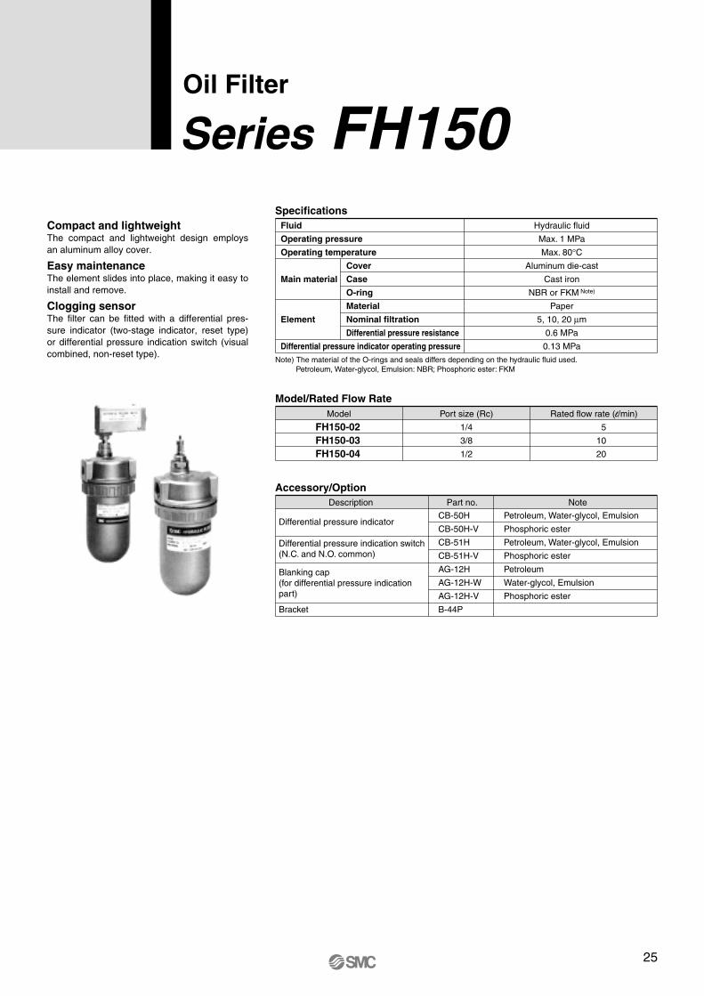
Compact and lightweight The compact and lightweight design employs an aluminum alloy cover.
Easy maintenance The element slides into place, making it easy to install and remove.
Clogging sensor The filter can be fitted with a differential pres-sure indicator (two-stage indicator, reset type) or differential pressure indication switch (visual combined, non-reset type).
FH150-02 FH150-03 FH150-04
1/4
3/8
1/2
5
10
20
Model Port size (Rc) Rated flow rate (l/min)
Model/Rated Flow Rate
Oil Filter
Series FH150Fluid
Operating pressure
Operating temperature
Main material
Element
Differential pressure indicator operating pressure
Hydraulic fluid
Max. 1 MPa
Max. 80°CAluminum die-cast
Cast iron
NBR or FKM Note)
Paper
5, 10, 20 µm
0.6 MPa
0.13 MPa
Cover
Case
O-ring
Material
Nominal filtration
Differential pressure resistance
Specifications
Note) The material of the O-rings and seals differs depending on the hydraulic fluid used.�Petroleum, Water-glycol, Emulsion: NBR; Phosphoric ester: FKM
CB-50H
CB-50H-V
CB-51H
CB-51H-V
AG-12H
AG-12H-W
AG-12H-V
B-44P
Petroleum, Water-glycol, Emulsion
Phosphoric ester
Petroleum, Water-glycol, Emulsion
Phosphoric ester
Petroleum
Water-glycol, Emulsion
Phosphoric ester
Differential pressure indicator
Bracket
Differential pressure indication switch (N.C. and N.O. common)
Blanking cap (for differential pressure indication part)
Description Part no. Note
Accessory/Option
25

Blanking cap
Cover
Case
Clamp ring
Element q O-ring
w O-ring
INLET OUTLET
Spring
Differential pressure indicator
Differential pressure indicator
INLET OUTLET
Differential pressure
indication switch
Differential pressure indication switch
INLET OUTLET
No.Descrip-
tion Hydraulic fluid type
Petroleum, Emulsion, Water-glycol
Phosphoric ester
Model
FH150-
FH150-
02 03 04 02 03 04
JIS B2401 -1A-P30
JIS B2401 -4D-P30
O-ring for cover case
O-ring for element
Standard Standard
1A-S65
4D-S65
FH 1 50 0 1 002 P 005Hydraulic filter
02 03 04
1/4
3/8 1/2
Port size (Rc)
Differential pressure indication
1 None
Relief valve
BNil None
With bracket
Bracket
005 010 020
5 µm10 µm20 µm
Nominal filtration
PM
Paper Micromesh
Element
Replacement Element Part No. (including O-ring for element)Model
FH150-02 FH150-03 FH150-04
5 µm
EP910-005N
10 µm
EP910-010N
20 µm
EP910-020N
Element size
ø53 x 90
Note 1) The symbol at the end of the element part no. indicates the hydraulic fluid type. �N: Petroleum, V: Phosphoric ester, W: Water-glycol, Emulsion (10 µm only)
Note 2) Refer to page 32 for non-standard filtration. Note 3) Above elements require one element per filter.
50 Element downward removal, threaded
Construction/Connection
Oil filter
How to Order
1 Max. 1 MPa
Operating pressure
045
None Differential pressure indicator Differential pressure indication switch Note)
Note) N.C. and N.O. common
Note) The non-standard filtration is for micromesh elements only. Refer to page 32 for details.
Note) 10 µm only for water-glycol or emulsion.
Hydraulic fluid012
Petroleum Water-glycol, Emulsion Phosphoric ester
Construction/Seal List
Replacement Seal List (One each of the O-ring types listed below is required per filter.)
Made to OrderNil X0
None Non-standard filtration
26
Series FH150

View port
COM.N.O.N.C.
G1/2
View port
Reset button
Two indication methods are available: differen-tial pressure indicator and differential pressure indication switch. These can be mounted on all filter models.
L Differential pressure indicator • Operating pressure—0.13 MPa
• Once a value is displayed, it will continue to be displayed until reset, even if the pump is stopped. (2-stage display reset type)
• Perform element replacement when the red ring floats up and covers the entire view port.
L Differential pressure indication switch • Operating pressure—0.13 MPa
• When a value has been displayed, it will be automatically reset when the pump is stopped. (Non-reset type)
• This is a visual dual-purpose 2-stage display. Perform element replacement when the switch has actuated (when the red ring floats up and covers the entire view port).
• N.C. and N.O. common
Differential Pressure Indication
qMounting • Confirm INLET and OUTLET before mount-
ing. Then connect so that the case is oriented downward. For maintenance, make sure to provide sufficient space above the filter for re-moving the element.
wOperation
• Operation of the differential pressure indicator in cold weather, such as during winter, mostly occurs due to high viscosity, so check wheth-er it is from clogging or not after normal oper-ation starts.
•Once the differential pressure indicator is ac-tuated, the indication continues to be dis-played until the indicator is reset (by depress-ing the reset button), even if the pump stops operating.�Reset after replacing the element and restart-ing operation, or after normal operation starts in cold weather such as during winter.
• When using a differential pressure indication switch and if a filter clogged signal is incorpo-rated into the sequence circuit of the ma-chine, make sure to design the system so the filter clogged signal does not operate until normal operation starts.
eElement replacement
• When the pressure difference reaches 0.13 MPa during operation (actuating the differen-tial pressure indicator), stop operation and re-place the element.
• When replacing the element, drain the fluid from the case. Also, check the O-rings and replace them if they are damaged.
rOther
• Refer to the operating manual regarding the tightening torque for clamping ring.
Handling Precautions
0.05 0.04
0.03
0.02
0.01
0.005
0.001
Pre
ssur
edr
op(M
Pa)
Flow rate (l/min)
2 3 4 65 7 8 9 10 20 30 40 50
Conditions Fluid: Turbine oil Class 2 VG56 Measured pressure: 1 MPa
Viscosity: 45 mm2/s Filter material: Paper Nominal filtration: 10 µm
FH150-02 to 04
02
03
04
Flow Characteristics
Microswitch Rating
Rated voltage
Normally closed
Normally open
Resistance load
555550.4 0.3
Non-inductive load (A) Inductive load (A)
AC125 AC250 DC8 DC14 DC30 DC125 DC250
Normally closed
Normally open
Light load
1.5 1
0.7 0.5
Normally closed
Normally open
Inductive load
44
440.4 0.3
5 4
Normally closed
Normally open
Motor load
2.5 1.5
1.3 0.8
3330.1 0.05
3330.1 0.05
Precautions 1. The figures in the above table indicate stationary
current. 2. An inductive load has a power factor (AC) of 0.75 or
more, and a time constant (DC) of 7 msec or less. 3. A light load has an inrush current 10 times greater. 4. Lead wires are connected using a screw tightening
terminal. 5. The electrical entry is equipped with a conduit
(G1/2) and grommet. 6. Please wire freely to the microswitch indication
symbol 1(COM.), 2(N.C.) and 3(N.O.). 7. If a holding mechanism is necessary for the non-
reset type, provide it using electric circuits.
(V)
27
Oil Filter Series FH150

ø16
Differential pressure indicator
(34)
29
H
AEF
BC
G
J
IN- LET
D(E
lem
entr
emov
aldi
men
sion
)
29
2 x Rc (d)
OUT- LET INLET
Differential pressure indication switch
Differential pressure indicator
Differential pressure indication switch
(65)
29
62
OUTLET
FH150-02 FH150-03 FH150-04
Model
1/4
3/8
1/2
d
80
A
139
B
168
C
230
D
50
E
15
F
25
G
7
H
6.5
J
0.7
Weight (kg)
(mm)
Dimensions
28
Series FH150

Magnetic separator
Magnetic separator
Magnetic separator
q U-turn flow type w Underflow type e Overflow type
These magnetic separators protect machinery from malfunctions, reduced precision, and burnout by adsorbing and eliminating contaminants in the fluid by means of magnetism. This helps extend the service life of hydraulic equipment.
Zero running cost Since there are no consumable parts, the run-ning cost is basically zero and the magnetic separator can be used semi-permanently.
Extends service life of hydraulic fluid By adsorbing and eliminating contaminants, the magnetic separator retards deterioration of the hydraulic fluid and makes it possible to extend the fluid replacement time.
Reduced maintenance costs The magnetic separator prevents mechanical problems caused by contaminants such as abrasive particles and greatly reduces mainte-nance costs.
Contaminant density of 200 ppm Separator after contaminant adsorption
Fluid after cleaning with magnetic separator (5 ppm)
Fluid
Operating temperature
Fluid speed
Max. 80°C3 m/min or less
FHMN: Petroleum, Water-glycol, Cutting oil, Emulsion
FHMV: Phosphoric ester
Specifications
FHMl-055 FHM-100 FHM-200
20
100
200
0.2
0.9
2.5
l55 x t20
l100 x t30
200 x 140 x t40
Model Applicable fluid storage volume (l/unit) Note) Weight (kg)Dimension (mm)
Model
Magnetic Separator Installation Examples
Magnetic Separator
Series FHM
Note) For example, three FHM100 magnetic separator units would be sufficient for a 300-liter fluid storage tank.
29

Magnet
Rubber caseAdsorption surface
Base plate
MagnetCover
Adsorption surface
Hexagon socket head cap screw
Hexagon socket head cap screw
Base plate
MagnetCover Adsorption
surface
Fluid Iron Content Elimination Performance by Iron Particle Concentration
100
90
80
70
60
50
40
30
20
10
0
Elim
inat
ion
ratio
(%)
Flow-back count
1 5 10 50 100
FHMl-055 Fluid: Hydraulic fluid
100 200 300 400 500
100
90
80
70
60
50
40
30
20
10
0
100 200 300 400 500
Elim
inat
ion
ratio
(%)
Flow-back count
1 5 10 50 100
FHM-200 Fluid: Hydraulic fluid
Example: Elimination ratio and concentration after using the FHM-100 for one hour under the following conditions. Conditions
Explanation of graph
Explanation of graph
FHM N 055
055 l55 x t20
Main unit representative dimensions
Magnetic separator
Petroleum, Water-glycol, Cutting oil, Emulsion
Phosphoric ester
Fluid
N
V
FHM 100
100 200
l100 x t30 200 x 140 x t40
Main unit representative dimensions
Magnetic separator
FHMl-055
FHM-200
FHM-100
100
90 80
70
60
50
40
30
20
10
0
75
Elim
inat
ion
ratio
(%)
Flow-back count
1 5 10 5030 100
FHM-100 Fluid: Hydraulic fluid
100 200 300 400 500
How to Order
1. Volume of fluid in tank: 200 l2. Pump-out volume: 100 l/min3. Contaminant concentration of used fluid: 500 ppm (initial concentration, percentage by volume) 4. Number of separators: 2 pcs. (applicable fluid storage volume of 100 l/unit)
Calculate the flow-back count (N).
Based on the elimination ratio data for the FHMl-100 and the point where the 500 ppm line and flow-back count 30 line intersect (one hour after starting operation), the result is 75%.
N = = = 30Pump-out volume x Operation time Volume of fluid in tank
100 x 60 200
Construction
30
Series FHM

20l
55
FHMl-055
FHM-200
FHM-100
200
140
7020
40
Hexagon socket head cap screw
(M6 x 10) 4 pcs.
115
l10
0
15
30
Hexagon socket head cap screw
(M6 x 10) 2 pcs.
Mounting q The flat portion of the stainless steel cover functions as the con-
taminant adsorption surface. However, for FHMl-055, the flat por-tion of the magnetic material functions as the contaminant adsorp-tion surface.
w Mount the magnetic separator in a location where fluid is constant-ly flowing by in laminar flow.
e Avoid locations such as near the suction pipe or return pipe, pla-ces where there is turbulence, and locations where the flow speed is 3 m/min or greater.
r If necessary, fix the separator in place. If frequent cleaning will be necessary, it can be suspended from the top panel of the tank.
t If a fluid switch (built-in lead switch) or the like is used, it should be installed in a location where it will not be affected by magnetism from the separator. (Refer to the technical data sheet (SM-82-006) for information on magnetic fields.)
Maintenance q Clean the separator regularly. Make sure to clean it once the accu-
mulation of contaminants reaches a thickness of 20 mm or so. w Clean the adsorption surface of the separator by wiping away the
accumulated contaminants using a soft rag or the like.
Handling q Do not bring the top surface of the separator near magnetically at-
tractive objects such as iron plates. w Handle the separators individually and do not bring them into close
proximity with each other. e Be careful not to get your fingers caught between iron plates, etc.,
when installing the separator. r Do not bring objects that are affected by magnetism (cards with
magnetic strips, watches, etc.) near the separator.
Handling Precautions
Handle-equipped type Cover/handle-equipped type
Tank-fixed type
Dimensions
31
Magnetic Separator Series FHM

FHIA (Refer to P. 3.)
1/2
3/4, 1
1 1/4, 1 1/2
2
2 1/2, 3
3 1/2, 4
1/2, 3/4
1,1 1/4
1 1/2
2
2 1/2
3
3 1/2, 4
1/2, 3/4, 1
1 1/4, 1 1/2, 2
2 1/2, 3
3/8, 1/2
3/4, 1
1 1/4, 1 1/2
2
2 1/2, 3
3/4
1 1/4
1 1/2
3/4, 1
1 1/4, 1 1/2
2
2 1/2, 3
1/4, 3/8, 1/2
Replacement element part no.
Micromesh element (With relief valve)
—
—
—
—
—
—
EM520-*1*2
EM620-*1*2
EM720-*1*2
EM820-*1*2
EM920-*1*2
EM030-*1*2
EM130-*1*2
—
—
—
—
—
—
—
—
—
—
—
—
—
—
—
—
ø65 x l90
ø85 x l110
ø100 x l160
ø120 x l180
ø140 x l200
ø180 x l260
ø65 x l90
ø82 x l133
ø104 x l177
ø104 x l177
ø132 x l212
ø132 x l212
ø155 x l193
ø69 x l88
ø89 x l123
ø109 x l188
ø53.1 x l90
ø73.5 x l117
ø73.5 x l195
ø87.6 x l282
ø118.7 x l280
ø56 x l180
ø76 x l190
ø76 x l290
ø65 x l95
ø73.5 x l117
ø87.6 x l157
ø118.7 x l207
ø53 x l90
Description Model Port size
EM001H-*1*2
EM101H-*1*2
EM201H-*1*2
EM301H-*1*2
EM401H-*1*2
EM501H-*1*2
EM230-*1*2
EM330-*1*2
EM430-*1*2
EM530-*1*2
EM630-*1*2
EM730-*1*2
EM830-*1*2
EM220-*1*2
EM320-*1*2
EM420-*1*2
EM040-*1*2
EM910-*1*2
EM140-*1*2
EM930-*1*2
EM240-*1*2
EM601H-*1*2
EM701H-*1*2
EM801H-*1*2
EM810-*1*2
EM910-*1*2
EM020-*1*2
EM120-*1*2
EM040-*1*2
Micromesh element Element size
Vertical suction filter
Oil filter
Return filter
Vertical return filter
Line filter
Suction guard
Suction filter with case
FH150 (Refer to P. 26.)
FH100 (Refer to P. 22.)
FHBA (Refer to P. 19.)
FH34 FH44 FH54 FH64
(Refer to P. 15.)
FHG (Refer to P. 11.)
FH99 (Refer to P. 7.)
Note) In the table above ∗1 indicates nominal filtration and ∗2 indicates hydraulic fluid type.
Made to Order (Non-standard filtration)
X0Filter symbol (Refer to “How to Order” for each series)
Hydraulic Filter Non-Standard Filtration Replacement Element Part No.
Symbol (∗1)
003 005 010 020 040 074 105 149 270
µm35
10 20 40 74 105 149 270
Nominal FiltrationSymbol (∗2)
N
W
V
Type
Hydraulic Fluid
How to Order
Note) Made-to-order specifications (non-standard filtration rating) are available only for micromesh elements (element symbol: M).
Petroleum
Water-glycol, Emulsion
Phosphoric ester
32
Series FH Made to Order (Non-Standard Filtration)Please contact SMC for detailed specifications, lead times and prices.

Series FHSpecific Product Precautions Be sure to read this before handling. Refer to the back of page 1 for Safety Instructions.
Design
Caution1. Do not use at a pressure that exceeds the
operating pressure range. 2. Do not use at a temperature that exceeds
the operating temperature range. 3. Fluid
Do not use the product with gases. Do not use fluid other than hydraulic fluid.
4. Fatigue damage Under the following conditions, special measures are re-quired: 1. If the product will be subjected to pressure surges. 2. If the product is not mounted securely and will be subject to
friction or vibrations.
5. Corrosion The product may corrode depending on usage conditions and environment.
Selection
Warning1. When selecting products, carefully consider
the usage purpose, the required specifica-tions, and the usage conditions (fluid, pres-sure, flow rate, temperature, environment), and ensure that the specification range is not exceeded.
2. The fluid used must not be heated to the boiling point.
3. Do not use the product with air or other ga-ses under any circumstances.
4. Do not use the product in circumstances where it will be exposed to pressure that ex-ceeds the rated operating pressure range, such as with a water hammer or surge pres-sure.
Fluid
Warning1. Do not use fluid other than hydraulic fluid.
Piping
Caution1. Make sure to allow sufficient space for
maintenance when installing and piping. 2. Connections
Make sure no cutting chips from pipe threads or sealing ma-terial gets inside the piping. If sealing tape is used, leave 1.5 to 2 thread ridges exposed at the end of the male thread.
3. Filter installation Use stays or the like to secure the inlet and outlet pipes so that the filter unit is not subjected to external force such as vi-bration.
Operating Environment
Caution1. If the product is used in an environment or
location conducive to corrosion, discolora-tion or deterioration due to corrosion may occur.
2. Fatigue damage may occur if the product is used in a location subject to vibrations or impacts.
Maintenance
Caution1. The differential pressure will increase if the
filter becomes clogged with foreign matter. The differential pressure indicator operation pressure is the pressure difference at which the element should be replaced. When the pressure difference rises to this level, replace the element with a new one. A differential pressure indicator and differential pressure indication switch are available as op-tions.
33

Akihabara UDX 15F, 4-14-1, Sotokanda, Chiyoda-ku, Tokyo 101-0021, JAPAN Phone: 03-5207-8249 Fax: 03-5298-5362 URL http://www.smcworld.com © 2007 SMC Corporation All Rights Reserved
Specifications are subject to change without prior notice and any obligation on the part of the manufacturer.
Printing LY 13500DN Printed in Japan.D-DN
This catalog is printed on recycled paper with concern for the global environment.
∗ Page 32 Addition of Made to Order (Non-standard fitration) ∗ Number of pages from 48 to 52. LY
Record of changes
H edition