Embed Size (px)
Citation preview
Hydraulic &Offshore Supplies
YOUR GATEWAY TO GLOBAL SUPPLY
HOSE ASSEMBLIES FLANGES PIPE & TUBEPRESSURE TESTING EQUIPMENT PACKAGESWALFORM
HoseManufacturing Data

HOSE MANUFACTURING DATA
STORAGE Detailed recommendations for storage of product are contained in BS 5244, 1986 (1991). Tables 1, 2 and 3 of this document are produced with the kind permission of BSI. Hose & Hose Assemblies Stored as Separate Items Before fitting, all hose assemblies should be subjected to visual examination for evidence of deterioration. The recommendation in Tables 1 and 2 apply to stored hoses and assemblies, depending on their age.
TABLE 1 TEST RECOMMENDATIONS FOR RUBBER HOSES AGE RECOMMENDATIONS
Up to 3 years Use without further testing 3 to 5 years Use after representative samples subjected to a
proof pressure test 5 to 8 years Use after representative samples subjected to
proof, impulse and burst pressure tests, and cold bend and electrical tests
Over 8 years Scrap
TABLE 2 TEST RECOMMENDATIONS FOR RUBBER HOSES ASSEMBLIES
AGE RECOMMENDATIONS Up to 3 years Use without further testing 3 to 5 years Use only after subjecting each assembly to a
pressure test of 1.5 x design working pressure and representative samples to a burst pressure test
5 to 8 years As for 3 to 5 years plus impulse pressure test and cold bend and electrical tests on representative samples
Over 8 years Scrap
HHyyddrraauulliicc && OOffffsshhoorree SSuupppplliieess
Tel: +44 (0)191 549 7335 Fax: +44 (0)191 516 0004 Email: [email protected] Website: www.hos.co.uk

TABLE 3 TEST RECOMMENDATIONS FOR STORED EQUIPMENT AGE RECOMMENDATIONS
Up to 3 years Use without further testing 3 to 5 years Use only after subjecting each assembly to a
pressure test of 1.5 x design working pressure and representative samples to a burst pressure test
Over 5 years Scrap NOTE 1: It is important that hose assemblies fitted to stored equipment should be filled with the operating fluid with which they will be used on that equipment. NOTE 2: It is highly recommended that hose assemblies fitted to stored equipment in conditions of extreme temperature, humidity or ozone concentration (strong sunlight) should be tested after 1 year according to the criteria stipulated for 3 to 5 year old assemblies.
TABLE 4 TEST RECOMMENDATIONS FOR THERMOPLASTIC HOSE
AGE RECOMMENDATIONS Up to 5 years Use without further testing 5 to 8 years Use after representative samples subjected to
proof pressure test 8 to 12 years Use after representative samples subjected to
proof, impulse and burst pressure tests, and cold bend and electrical tests
Over 12 years Scrap
TABLE 5 TEST RECOMMENDATIONS FOR THERMOPLASTIC HOSE ASSEMBLIES
AGE RECOMMENDATIONS Up to 5 years Use without further testing 5 to 8 years Use only after subjecting each assembly to a
pressure test of 1.5 x design working pressure and representative samples to a burst pressure test
8 to 12 years As for 3 to 5 years plus impulse pressure test and cold bend and electrical tests on representative samples.
Over 12 years Scrap
HHyyddrraauulliicc && OOffffsshhoorree SSuupppplliieess
Tel: +44 (0)191 549 7335 Fax: +44 (0)191 516 0004 Email: [email protected] Website: www.hos.co.uk

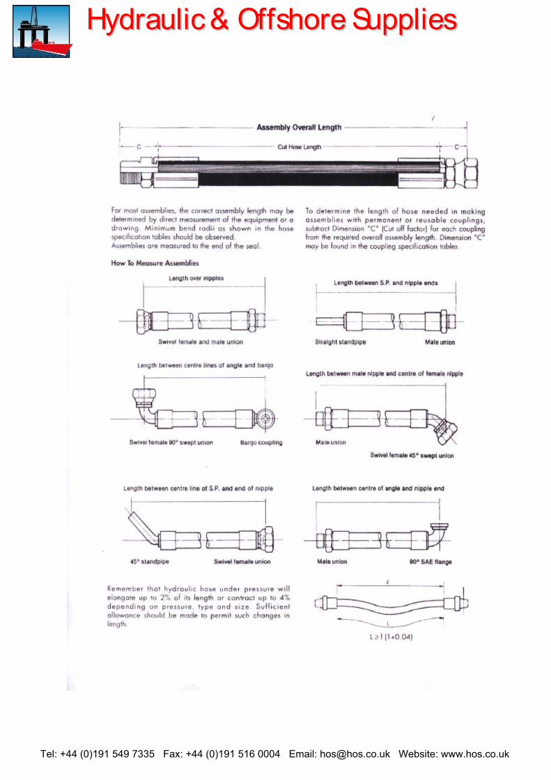
ROUTING In general, routing should be such that bends lower that minimum bend radius or tensile loading of the hose assemblies must be avoided. The minimum bend radius is measured to the inside of the bent hose and the length of the assembly should be such that there is a 25mm long straight portion of the hose at the inlet to each end fitting. Where abrasion of the product is likely, consideration should be given to extra protection. This can be provided in the form of steel or plastic spring guarding over the external surface of the hose preventing exposure to damage. To this end, specific attention must be paid to the movement of the hose when operating between components of a hydraulic system which move relative to each other. It is advisable to ensure that hose is routed such that there is no bending of the hose within 25mm of the end fitting to which it is attached and that where possible, assemblies are not manufactured with swept elbows at either end. When deciding the routing of hose assemblies specific attention should also be paid to clipping and/or clamping hoses at appropriate points.
INSTALLATION Before attempting to connect a hose assembly it is essential to ensure that the joining surfaces are completely free from foreign matter and from burrs, flash or fins. Damage to these surfaces, especially where metal to metal cone connections are concerned, may result in leakage. Also, hose assemblies should have been cleaned internally to avoid any contamination entering the system which may be residue of the hose assembly manufacture.
PROBLEM POSSIBLE CAUSE & MISAPPLICATION
SOLUTION
Hose bursts on outside of bend and is out of shape.
Hose bent too tight in routing. Reinforcement opened up too much on outside bend.
Increase hose length, also may be able to use different end fittings, i.e. swept 90 instead of straight.
Coupling blows off end when under pressure.
Incorrect coupling used. Couplings not crimped to correct swage dimension. Coupling not fully inserted. Hose not correct skived. Hose too short, twisted or bent too tight.
Check hose coupling compatibility, check swage information. Does routing cause excessive stress on assembly.
Hose liner swells or deteriorates, blocking fluid flow or leaking
Hose liner is not compatible with fluid. Temperature may be a factor.
Before making assembly, identify fluids and temperature in use. Check compatibility.
Wire reinforcement is rusty at site of hose burst.
Hose cover broken by cutting, abrasion, extreme temperatures, chemical attack, improper cover skiving, internal gas caused by blisters.
Use hose guard, nylon sleeve, anti‐abrasive cover hose. Check temperature & fluid compatibility. Cover may require perforating.
NOTE: IN SOME INSTANCES, FAILURE MAY BE CAUSED BY PREVIOUS REPAIRS.
HHyyddrraauulliicc && OOffffsshhoorree SSuupppplliieess
Tel: +44 (0)191 549 7335 Fax: +44 (0)191 516 0004 Email: [email protected] Website: www.hos.co.uk

FACTORS AFFECTING SERVICE LIFE
Main Causes
* Excessive Pressure
* Abuse
* End of Working
Contributory Factors
* Installation
* Below recommended minimum bend radius
* Twisting
* Pulling
* Temperature extremes
* Vibration
* Chemical attack
* High velocity oil erosion (hose tube)
* Ageing (ozone)
* Incorrect angle orientation
HHyyddrraauulliicc && OOffffsshhoorree SSuupppplliieess
Tel: +44 (0)191 549 7335 Fax: +44 (0)191 516 0004 Email: [email protected] Website: www.hos.co.uk

DO’S AND DON’TS TO PROLONG HOSE LIFE
DO Always use Hydraulic & Offshore Supplies fittings together with
Hydraulic & Offshore Supplies approved hose.
DON’T Ever mix and match hose and couplings
from different sources. Make hose assemblies from Hydraulic & Offshore Supplies matched components to ensure compatibility and performance.
DON’T Cut out a piece from an existing
assembly to remove the “bad bit” and put a new coupling on. If a hose has failed it is likely that the reinforcement has passed its working life. First‐aid repairs are potentially lethal and invalidate any manufacturer’s guarantee.
DON’T Alter the pressure relief valve in your
hydraulic system without considering whether the increased pressure will exceed the recommended max working pressures of your hose assemblies. If it will, replace the hoses with more suitable assemblies.
HHyyddrraauulliicc && OOffffsshhoorree SSuupppplliieess
Tel: +44 (0)191 549 7335 Fax: +44 (0)191 516 0004 Email: [email protected] Website: www.hos.co.uk
HHyyddrraauulliicc && OOffffsshhoorree SSuupppplliieess
Tel: +44 (0)191 549 7335 Fax: +44 (0)191 516 0004 Email: [email protected] Website: www.hos.co.uk

GUIDELINES FOR THE USE OF HYDRAULIC FLUID POWER
HOSE & HOSE ASSEMBLIES
HHyyddrraauulliicc && OOffffsshhoorree SSuupppplliieess
Tel: +44 (0)191 549 7335 Fax: +44 (0)191 516 0004 Email: [email protected] Website: www.hos.co.uk

ANGLE ORIENTATIONS
Refer to the following picture to define the correct fitting orientation.
Keep straight the further end and rotate clockwise the closest end of the requested angle.
0°
45°
90°
135°
180°
235°
270°
315°
Furthest End
HHyyddrraauulliicc && OOffffsshhoorree SSuupppplliieess
Tel: +44 (0)191 549 7335 Fax: +44 (0)191 516 0004 Email: [email protected] Website: www.hos.co.uk

STANDARD 316 STAINLESS STANDARD 316 STAINLESS 316 STAINLESS 316 STAINLESS 316 STAINLESS STANDARD STANDARD 316 STAINLESS STANDARD STANDARD STANDARD 316 STAINLESS STANDARD STANDARD 316 STAINLESS STANDARD STANDARD 316 STAINLESS STANDARD STANDARD 316 STAINLESS STANDARD 316 STAINLESS STANDARD 316 STAINLESS
SKIVE SKIVE SKIVE SKIVE NO SKIVE NO SKIVE NO SKIVE PRE-CRIMP NO SKIVE NO SKIVE NO SKIVE NO SKIVE PRE-CRIMP NO SKIVE NO SKIVE PRE-CRIMP NO SKIVE NO SKIVE NO SKIVE PRE-CRIMP NO SKIVE NO SKIVE PRE-CRIMP NO SKIVE NO SKIVE PRE-CRIMP NO SKIVE NO SKIVE PRE-CRIMP NO SKIVE SKIVE SKIVE NO SKIVE NO SKIVE
0001 X001C 0002 X0022 001C 0022 0011 G X001C X0022 0022 0021 G X0022 001C G X001C 001C 0022 G X0022 0022 G X0022 001C G X001C 001C G X0022 0002 X0022 0022 X002214.9 16.6
20 21.017.2 16.4 17.8 17.7
23 21 22.0 21.519.2 16.8 20.5 19.2
23 19.5 22.0 21.521.1 20.4 21.7 21.5
24 22.0 24.0 21.525.0 23.3 25.1 24.825.0 24.5 25.0 23.528.3 27.1 28.7 28.027.0 27.0 27.0 28.032.3 29.5 33.0 32.831.0 30.5 31.0 31.039.9 39.0 40.5 39.437.0 39.0 37.0 35.047.4 49.0 50.8 52.742.0 39.5 43.0 40.553.0 53.4 57.2 56.544.0 46.5 45.0 48.065.9 68.2 69.5 70.660.0 62.0 61.0 57.0
STANDARD STANDARD STANDARD MULTISPIRAL316 STAINLESS MULTISPIRAL INTER-LOCK 316 STAINLESS STANDARD STANDARD MULTISPIRAL INTER-LOCK INTER-LOCK 316 STAINLESS 316 STAINLESS STANDARD STANDARD INTER-LOCK INTER-LOCK 316 STAINLESS 316 STAINLESS 316 STAINLESS 316 STAINLESS STANDARD 316 STAINLESS STANDARD 316 STAINLESS
NO SKIVE NO SKIVE SKIVE SKIVE SKIVE NO SKIVE SKIVE SKIVE SKIVE SKIVE NO SKIVE NO SKIVE SKIVE SKIVE SKIVE NO SKIVE NO SKIVE NO SKIVE NO SKIVE SKIVE SKIVE NO SKIVE NO SKIVE NO SKIVE NO SKIVE NO SKIVE NO SKIVE NO SKIVE SKIVE NO SKIVE SKIVE NO SKIVE
BMC1 BMC2 0009 0019 X0022 BMC1 004H 0019 004N X004N BMC1 BMC2 0013S 004N 0013 X004N X0013 BMC1 BMC2 004N 0013 X004N X0013 SMOOTH CONVOLUTED 2 BRAID SMOOTH CONVOLUTED 0001 X001C 0002 X0022PTFE-03 XPTFE-0310.3 10.3
18.4 18.4 18.4 23.5 PTFE-04 PTFE-04-C XPTFE-04 XPTFE-04-C 17.2 16.4 17.8 17.722.0 30.0 21.5 34.0 12.0 13.15 12.0 13.15 23 21 22.0 21.5
19.2 16.8 20.5 19.223 19.5 22.0 21.5
23.2 23.4 22.4 27.0 PTFE-06 PTFE-06-C PTFE-06-D XPTFE-06 XPTFE-06-C 21.1 20.4 21.7 21.525.5 31.0 21.5 37.0 16.0 15.20 16.47 16.0 15.20 24 22.0 24.0 21.526.5 27.0 25.7 32.0 PTFE-08 PTFE-08-C XPTFE-08 XPTFE-08-C 25.0 23.3 25.1 24.828.0 34.0 23.5 36.0 18.9 19.40 18.9 19.40 25.0 24.5 25.0 23.530.0 29.8 29.4 PTFE-10 PTFE-10-C XPTFE-10 XPTFE-10-C31.0 38.0 28.0 22.8 23.10 22.8 23.1034.3 34.9 33.8 34.6 34.1 33.0 34.1 34.1 PTFE-12 PTFE-12-C XPTFE-12 XPTFE-12-C33.0 39.0 31.0 39.0 52/15 52/15 52/15 52/15 26.2 26.35 26.2 26.3542.3 42.7 40.2 42.2 41.5 41.5 41.5 42.6 42.5 42.6 PTFE-16 PTFE-16-C XPTFE-16 XPTFE-16-C48.0 56.0 35.0 56.0 64/17 64/17 64/17 64/17 64/17 64/17 33.2 32.5 33.2 32.551.2 52.4 48.5 50.5 50.5 53.8 54.2 53.8 54.2 PTFE-20-C XPTFE-20-C54.0 40.5 54.0 74/22 74/22 74/22 74/22 74/22 74/22 44.3 44.359.6 56.5 57.9 57.0 57.0 60.5 60.3 60.1 60.3 PTFE-24-C XPTFE-24-C62.0 48.0 62.0 81/22.5 81/22.5 81/22.5 74/22.5 81/22.5 74/22.5 50.0 50.073.0 70.5 72.0 72.0 77.9 77.9 PTFE-32-C XPTFE-32-C64.0 64.0 85/30 85/30 85/30 85/30 61.6 61.6
STANDARD STANDARD STANDARD 316 STAINLESS STANDARD 316 STAINLESS STANDARD 316 STAINLESS STANDARD 316 STAINLESS STANDARD STANDARD STANDARD PRE-CRIMP STANDARD 316 STAINLESS STANDARD STANDARD PRE-CRIMP 316 STAINLESS 316 STAINLESS 316 STAINLESS 316 STAINLESS 316 STAINLESS
NO SKIVE NO SKIVE NO SKIVE NO SKIVE NO SKIVE NO SKIVE NO SKIVE NO SKIVE NO SKIVE NO SKIVE NO SKIVE NO SKIVE NO SKIVE NO SKIVE NO SKIVE NO SKIVE NO SKIVE NO SKIVE NO SKIVE NO SKIVE NO SKIVE NO SKIVE NO SKIVE
0003 0003 0021 X001C 0007 X0007 0007 X0007 0007 X0007 0007 0022 0011PS G G X0022 42100 0022 G X0022 0009 0019 1AW-06 X0022 0022 X0022 001C X0022 0007 X00070007-03-IM
13.5
Interlock Fitting
316 Stainless Steel
LegendDimensions: mm - Average tolerance +0.00/-0.2 Doc No. 01/11 Issue
13 15/09/2010
Standard Insert
Long Tail Multispiral InsertCHART OF RECOMMENDED SWAGING DIAMETERS
2''
3/8''1/2''5/8''
1.1/4''1.1/2''
Product
STANDARD
EN 853 1SN - DIN 20022 1SN - TFD0011 & TFA0011I
18.0 15.3 15.5
STANDARD
EN 853 2SN - DIN 20022 2SN - TFD0021 & TFA0021I
EN 853 2ST SAE 100R2A
TFD0002
HIPAC 3 BRAID THE003K
17.819.5
2SC ANTI-ABRASIVE TFEPO2KI
16.118.1
21.7
SAE 100 R17
27.5
17.8
SAE 100 R16
17.8 18.0 17.019.521.6
EN 853 1ST SAE 100R1A
TFD0001
57.3
38.5
24
32
12
16
Insert
19.823.527.0
3/16''1/4''
03
04
05
06
16.116.6
18.2
15.216.518.7 18.0
38.3 37.547.553.6
18.820.524.5
55.568.5
30.5
VAMAC TF-VAMAC
20
19.9
Product
Ferrule
16.5
19.5
14.515.8
3/16''1/4''
Ferrule
08
5/16'' 05
10
12
24
3/4''1'' 16
20
10
10
5/16''3/8''
1''1.1/4''1.1/2''
2''
3/16''1/4''
5/8''
1.1/4''1.1/2''
3/4''1''
12
16
2''24
32
20
39.0
38.530.038.4
EN 856 R15 - SAE 100 R15 TFS0015
41.0 39.450.4
32.5
20.825.127.731.7
28.324.0 25.128.030.7
16.5
31.0
18.520.8
39.0
20.524.0
26.5 27.531.1
24.3
68.7
48.0
72.357.9
53.257.1
49.754.570.4 70.0 70.8
39.9 40.251.754.9
51.058.071.0
18.420.322.325.8
19.521.525.028.0
36.8
29.433.440.5
22.6 23.0
29.0
16.1
26.4 27.423.5
17.719.1 19.516.7 18.0
16.118.119.623.227.130.5 31.5
39.5
27.030.539.0
21.625.228.232.4
17.019.221.024.727.531.339.648.0
17.318.821.025.328.231.640.3
22.8
29.939.2 42.0 38.5
23.227.1
17.118.7
32.6 30.5
19.6
39.5
17.018.8
21.625.228.232.439.4
20.524.527.531.5
18.0
21.624.8
06
08
05
Insert
03
Ferrule
1/2''
EN 856 R13 - SAE 100 R13 TFS0013
EN 856 4SP - DIN 20023 4SP TFD04SP
EN 857 1SC TFE001K
EN 857 2SC TFE002K
24.828.5
16.018.0
13.515.2
21.0
3/4''
5/16''3/8''1/2''5/8''
08
04
Product
46.3
03
04
Insert
11.814.1
06 21.0
32
17.0 17.018.5
22.318.3 19.5
25.020.518.5
19.524.3 25.0
11.814.1
36.8 36.5 37.529.0
25.726.730.5
13.014.717.118.423.126.3
21.118.4
14.617.0
SAE 100 R3
TF-0003
29.733.240.546.2
34.541.4
18.622.8
18.322.3
25.6
36.0 36.530.2
68.258.0
29.0 29.0
49.841.1
18.6
25.629.036.8
22.8
16.117.5
26.9
38.4
25.928.436.6
12.013.8
22.018.8
12.013.8
16.3
SAE 100 R4 TFS0004
SAE 100 R6 TF-0006
SAE 100 R7 TF-0007
SAE 100 R8 TF-0008
16.1 16.3 16.1 17.7
1 WIRE BRAID TF-MT1-
14.116.4
16.117.5
15.0
20.0
46.0
32.239.3
23.126.330.236.0
14.7
18.4
2SN JETWASH HOSE TFN0021 &
TFB0021
SAE 100 R14 TF-PTFE
STANDARD
1SN JETWASH HOSE TFN0011 & TFB0011
17.7 17.7
700 BAR THERMOPLASTIC HOSE
18.2
AIR HOSE TF-AIR
MULTIPURPOSE HOSE
TF-TU25
16.718.720.824.3
55.2
STANDARD
46.4
EN 856 4SH - DIN 20023 4SH TFD04SH
23.6
17.119.0
25.021.0
24.8
31.628.0
32.239.6 38.6
ORANGE THERMOPLASTIC
SEWER HOSE TF-1PS
31.1
WIRE BRAIDED THERMOPLASTIC COVER HOSE ALSO SUITABLE FOR SOLVENTS AND PAINTSPRAY
2 WIRE BRAID TF-MT2-
HHyyddrraauulliicc && OOffffsshhoorree SSuupppplliieess
Tel: +44 (0)191 549 7335 Fax: +44 (0)191 516 0004 Email: [email protected] Website: www.hos.co.uk


![SAE Flange Catalogue - Hydraulic and Offshore Supplies Flange Catalogue.pdf · 2015-05-01 · [ IV ] Angewandte Normen Für unsere Flansche werden folgende Normen berücksichtigt:](https://img.dokumen.tips/doc/110x75/5e26efd15e21aa0c0903da74/sae-flange-catalogue-hydraulic-and-offshore-supplies-flange-2015-05-01-.jpg)