Embed Size (px)
Citation preview

Hydran M2
GE Monitoring & Diagnostics
Product Presentation

Utility value/MM customers
Hydran M2
Product Summary
What is it?
It’s a continuous on-line dissolved gas and moisture in oil monitoring device that alerts personnel of developing fault conditions in their transformer
GE Differentiated Value Proposition
• Cost effective solution to help prevent unplanned outages by detecting early developing key fault gases and moisture ingress in the transformer main tank.
• Expandable monitoring capabilities (on board transformer models) to provide further critical information on transformer condition.
• Single valve installation with no consumables to replace and no field calibration required.

Dissolved Gases

Why monitor Dissolved Gases?
A sudden increase of dissolved gas level is the best indicator of a developing incipient fault
o The oil is in contact with every component in the main tank.
o When a fault occurs in a component, oil will be degraded and gases will be generated
o Relative gas concentration changes in relation to the nature, severity and temperature of the fault
o Oil is a transport mechanism…… Gases are produced and distributed into the oil and the gas blanket or conservator

CC
HHHH
CC
HHHH
CC
HHHH
CC
HHHH
CC
HHHH
HH
H
HCC
H
H
H
HH
H
HC
HH
H
H
CC
HHHH
H
H
HC
C
HH
HH
Oil degradation – Typical oil Molecule

HYDROGEN H2
METHANE CH4
ETHANE C2 H6
ETHYLENE C2 H4
ACETYLENE C2 H2
Gases Generated During Breakdownof Dielectric Oil (Gibeault / Hall / Noirhomme)
References:M. Duval, Electra,133,40 (1990 ).T.V. Oommen, Gas Generation in Power Transformers
GA
S C
ON
ST
ITU
EN
TS
250 750 1000 1250 1500 1750500
Fault Temperature ( C )
2000

HOH
CO HOH
HOH
CH2OH
OH
O
O H
HH
HO
C
OHH
O CHO
H
H
H
WATER
WATER
WATER
FURAN
CARBONMONOXIDE
Paper degradation – gases developed
Paper Molecule

CARBON MONOXIDE CO
CARBON DIOXIDE CO2
Gases Generated During Breakdownof Cellulosic Insulation (Gibeault / Hall / Noirhomme)
References:M. Duval, Electra,133,40 (1990 ).T.V. Oommen, Gas Generation in Power Transformers
GA
S C
ON
ST
ITU
EN
TS
Fault Temperature ( C )200 250 300100 500400

Dual Hydran Sensor

HYDRAN M2 - Dual Sensor
Moisture sensor
Gas sensor
• The Sensor
The M2 unit

The CPU - Signal conditioning
Hydran Technology - Gas detection
i
H2
CO
Sensor
COO2
Electro-chemical Detector
Membrane
H2
+ _
C2H2
C2H4
V Signal
• The membrane is a solid film of Fluoro polymer, extremely stable and chemically resistant
• The oil supplies combustible gases and the Oxygen comes from the air
• No internal reagent required to generate the signal

Gas sensor Calibration
• Check Sensor Integrity (Gas phase; 2% H2) After sensor assembly (2 hours)
• Determine the Calibration parameters (H2 in Oil) (2 weeks)– Temperatures: 10, 45 & 70 °C– Concentrations: 0, 100, 350, 1000 & 2000 ppm– Computation of transfer parameters– Comparison with DGA values
• Check System Integrity (Gas phase; 2% H2)

Why monitor Moisture in Oil?
• Water in the oil can lead to water condensation
• Water in oil Increased risk of bubbling formation at high load
• Increased water in oil = Accelerates the rate of insulation aging as it reduces dielectric strength
• Water content measured in ppm is the water contained in the oil
• Measuring moisture in oil is easily done!!

Rectifier Transformer B21 MVA OFWF
0
10
20
30
40
50
Jan-04 Jan-05 Jan-06 Jan-07
Tem
pera
ture
(oC
)
0
3
6
9
12
15
Wat
er in
Oil
(ppm
)
Moisture in Oil vary with operating conditions
Top Oil Temp
Water in Oil

Moisture Sensor long term stability
Long Term Stability of Moiture Sensor
0
1
2
3
4
5
6
7
8
9
10
Jan-04 Jan-05 Jan-06 Jan-07
Date
%R
H H
2O
0
5
10
15
20
25
30
35
40
45
50
To
p O
il T
emp
erat
ure
°C
Top Oil Temp
Water in Oil

H2O
Hz SignalpF
Oil Cavity
Hydran Sensor - Moisture detection
Sensor The CPU - Signal conditioning
H2O
H2O
H2O
OSC
Polymeric Film
-Polymeric moisture sensitive capacitor

Hydran M2 - Sensor Data Sheet
Unit serial number
Unit configuration: I/O’s and Comms
Sensor serial number
Sensor gas & moisture calibration parameters
Customer name

Dynamic Oil Sampling(DOS)

DOS - Effectiveness
•Distance between Hydran M2 and transformer tank

Dynamic Oil Sampling
20
25
30
35
40
45
0:00 6:00 12:00 18:00 0:00
Time
Sen
sor
Tem
per
atu
re °
C
DOS - Functionality
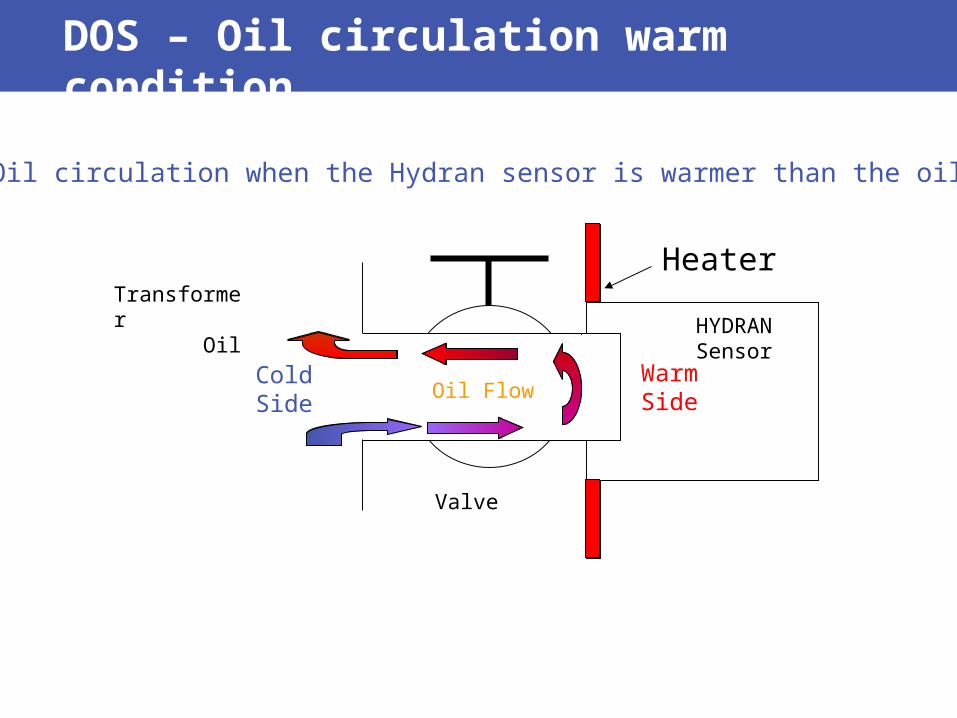
DOS – Oil circulation warm condition
WarmSide
ColdSide
HYDRANSensor
Valve
Transformer Oil
• Oil circulation when the Hydran sensor is warmer than the oil
Oil Flow
Heater

• Oil movement seen via infrared camera when the Hydran sensor is warmer than the oil in the transformer
DOS – Oil circulation warm condition
•Temperature gradient when the Hydran sensor is warmer than the oil

WarmSide
ColdSide
HYDRANSensor
Valve
Transformer Oil
• Oil circulation when the Hydran sensor is cooler than the oil
Oil Flow
Cooler
DOS – Oil circulation cool condition

•Temperature gradient when the Hydran sensor is cooler than the oil
• Oil movement seen via infrared camera when the Hydran sensor is cooler than the oil in the transformer
DOS – Oil circulation cool condition

Lukewarm
HYDRANSensor
Valve
Transformer Oil
• Oil circulation when oil temp and sensor temp are the same
Oil Flow ? LukewarmAlternating Oil Flow
DOS – Oil circulation no condition

• Effective of dynamic oil sampling on the Hydran reading over a long period
Hydran Reading Long Term Stability
0
10
20
30
40
50
60
70
80
90
100
Jan-04 May-04 Sep-04 Jan-05 May-05 Sep-05 Jan-06
Date
Hyd
ran
Rea
din
g P
PM

Product Overview

Single Valve Installation

External Components
Hydran M2 s/nProduct I/O information
Dual sensor
Ground lug
(6x) Cables conduits entry
Sensor clamp
Heater plate

AC power
Display
Alarms Contacts
Expansionport(for future use)
Internal Components
Local Keypad
4-A fuse

RS-232 port
RS-485 Network / TDM connector
Optional I/O interfaces max 4
Ethernet or Modem card
Internal Components

Product Specifications, Features & Options

Measures the concentration of:•Moisture in Oil – RH% (0-100%)
A combined incipient fault gas reading of: •Hydrogen (H2) – 100%•Carbon Monoxide (CO) – 18%•Ethylene (C2 H4) – 1.5%•Acetylene (C2 H2) – 8%
Specifications
• Accuracy– Gas: +/- 10% of reading +/- 25 PPM for Hydran
gas
– Moisture: +/- 2% of reading for %RH

When to use Heated Finned adaptor?
• Oil at the valve: -50 to +105°C (-58 to +221°F). Possible short-duration exposure up to 120°C (248°F).
• Ambient temperatures greater than 40°C, a finned high temperature adaptor is required.

• Local RS232 port
• RS 485 port for remote communication and for networking of multiple units up to 32 units
• Ethernet or Modem connectivity
• Multiple protocols user selectableo DNP 3.0 o Modbuso Hydran® Protocol (upon request only)
• Local or remote interface software Hydran® M2 Host and Multi Host also Preception
Communication Capabilities
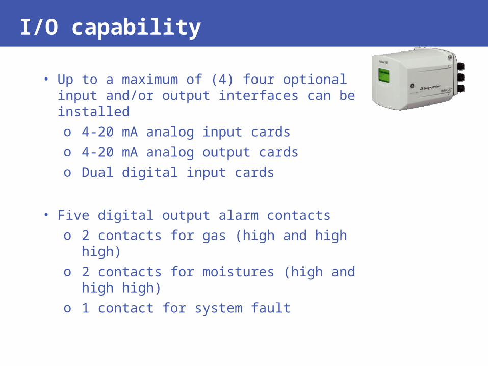
I/O capability
• Up to a maximum of (4) four optional input and/or output interfaces can be installed o 4-20 mA analog input cardso 4-20 mA analog output cardso Dual digital input cards
• Five digital output alarm contacts o 2 contacts for gas (high and high high) o 2 contacts for moistures (high and high
high)o 1 contact for system fault

Data logging
• Hourly and daily trend calculation with alarming
• Historical data (default value):o Short Term: 1 record every 15 minutes for a
capacity of 50 dayso Long Term: 4 records a day for a capacity of 3
years and 3 monthso Event History: 3,120 records (alarms, lost of
power, etc.)o Service History: 1,470 records (sensor test,
service information)

Expandable monitoring solution
•Top Oil temp
•Bottom Oil temp
•Ambient temp
•Transformer Load
•OLTC temp
•OLTC position
•Transformer Parameters
-Transformer Parameters-Data acquisition/processing-On-line models-Data storage
Sensor signals
Significant Information Transformer models
•Winding Temp Hot Spot
•Insulation Aging
•Moisture in Barriers, Moisture in Winding Insulation, Bubbling Margin
•Cooling Efficiency
•Tap Changer Over heating, Tap Changer position
•Dynamic Loading
MO150, M2, Transfix Plus
• Easily upgradeable for a more complete transformer monitoring solution

Who can benefit from using HM2
T&D utilities o Generationo Transmissiono Distribution
Industrials o Aluminum smelterso Steel millso Petro-Chemicalo Mining plants.
Transformer manufacturers (OEMs) - Including in their offering monitoring at the lowest possible cost.

• Single valve mounting, one sensor for direct & continuous monitoring of combustible dissolved gas-in-oil and moisture-in-oil
• Sensor measurement update time is under 10 minutes for 90% step change in gas concentration
• No moving parts, no pumps required, no carrier gas (no compressed gas bottle) required, no additional oil lines required
• Internal Sensor self testing feature (automatic and user initiated)
• Hourly and Daily trending user adjustable alarm settings that will alert personnel immediately upon detection of incipient fault gases and/or moisture levels
• Built in thermal condition system - Dynamic oil sampling
• All in one unit - Transformer models capabilities
Product Benefits

Data Correlation & Validation

Extracting an oil sample
Glass syringe
Sensor purging port

How do I validate the M2 PPM reading?
Local Hydran® Reading: 220 PPM
Hydrogen (H2) 100% x
Carbon Monoxide(CO) 18% x
Acetylene (C2H2) 8% x
Ethylene (C2H4) 1.5% x
DGA Results
130
300
2
15
130
54
0.16
0.23
Calculated Hydran Reading184.4

Data Analysis - Hydran Gas Reading Validation
• Hydran® Gas Reading Validation cont.
› Calculated DGA Reading: 185 PPM
› Hydran® Reading: 220 PPM
173P
PM
267
PP
M
- 25 PPM + 25 PPM- 10 % + 10 %220 PPM
Hydran® Reading

Installation

Location on transformer
•Most common four locations to install the Hydran M2
Warning: If these typical locations cannot be used please contact GE Canada Customer Service for assistance.


![Hydran* M2 Transformer Gas Monitoring System Installation ... · [DE] (in German) WARNUNG: • Alle Abläufe in diesem Handbuch müssen strengstens befolgt werden. • Jede Abweichung](https://img.dokumen.tips/doc/110x75/5f04cf477e708231d40fd127/hydran-m2-transformer-gas-monitoring-system-installation-de-in-german-warnung.jpg)