Embed Size (px)
Citation preview

HYDRA ANTENNA
INSTALL INSTRUCTIONS
A step by step guide for self-installation of the Hydra antenna

ANTENNA SPECIFICATION ............................................................................................................................3
WHAT YOU NEED TO PROVIDE .....................................................................................................................4
SITE SURVEY SITE SELECTION ABOARD THE SHIP .............................................................................................................5
HYDRA TYPICAL MOUNTING EXAMPLE ........................................................................................................6
USE OF PEDESTAL .........................................................................................................................................6
INSTALLATION 1) REMOVE ANTENNA FROM PACKAGING .....................................................................................................7 2) REMOVE KIT BAG FROM BOX .....................................................................................................................8 3) REMOVE DOME LID ....................................................................................................................................9 4) REMOVE SAFETY BOLTS ...........................................................................................................................10 5) SECURE DOME .........................................................................................................................................11 6) ALIGNING THE ANTENNA ........................................................................................................................12 7) PLACING THE RUBBER MAT ONTO THE PEDESTAL ...............................................................................13 8) ATTACH DOME TO PEDESTAL AND ADDING LOCKTITE TO THE BOLTS .................................................14 9) SET UP AC – CONNECTION WIRING ........................................................................................................15 10) SET UP ETHERNET CONNECTION WIRING ...........................................................................................16 11) USE OF CRIMP TOOL .............................................................................................................................17 12) CONNECT THE CONNECTORS ...............................................................................................................18 13) CONNECT TO ANTENNA ETHERNET .....................................................................................................19 14) POWER THE ANTENNA ..........................................................................................................................20
FREE OFFER .................................................................................................................................................21
CONTENTS
Page 2

____________________________________________________________________________________________________________________________________________
Dish Diameter: 61cm ____________________________________________________________________________________________________________________________________________
Antenna Dimension: 79.3cm(H) x 62.2cm(D)____________________________________________________________________________________________________________________________________________
Antenna Weight (With Dome): 36 Kg____________________________________________________________________________________________________________________________________________
Radome Material: Plastic____________________________________________________________________________________________________________________________________________
Rx Frequency: 10.95-12.75GHz____________________________________________________________________________________________________________________________________________
Tx Frequency: 13.75-14.5GHz____________________________________________________________________________________________________________________________________________
Rx Gain: 35.7dBi @ 11.75GHz____________________________________________________________________________________________________________________________________________
Tx Gain: 37.2dBi @ 14.25GHz____________________________________________________________________________________________________________________________________________
G/T: 13.5dB/K@12GHz____________________________________________________________________________________________________________________________________________
BUC: 6W____________________________________________________________________________________________________________________________________________
LNB: Quad Band LNB____________________________________________________________________________________________________________________________________________
Stabilisation: 3-axis active stabilisation____________________________________________________________________________________________________________________________________________
Skew control: Automatic____________________________________________________________________________________________________________________________________________
Elevation Angle: -10° to +100°____________________________________________________________________________________________________________________________________________
Azimuth Angle: Unlimited____________________________________________________________________________________________________________________________________________
Cross Angle: +/-40°____________________________________________________________________________________________________________________________________________
Tracking speed: 40° per sec____________________________________________________________________________________________________________________________________________
Ships Motion: Yaw: +/- 8° at 20sec period____________________________________________________________________________________________________________________________________________ Pitch: +/- 7° at 8sec period____________________________________________________________________________________________________________________________________________ Roll: +/- 20° at 8sec period____________________________________________________________________________________________________________________________________________
Temperature: -20C to +55C____________________________________________________________________________________________________________________________________________
Input Power: 90-264VAC full range, 47-63Hz____________________________________________________________________________________________________________________________________________
Control Interface: Via local internet connection____________________________________________________________________________________________________________________________________________
Packing Size: 84 x 84 x 93cm____________________________________________________________________________________________________________________________________________
Gross Weight: 46Kg____________________________________________________________________________________________________________________________________________
Packaging: Cardboard____________________________________________________________________________________________________________________________________________
CONTENTS HYDRA SPECIFICATIONS
Page 3
WHAT YOU NEED TO PROVIDE
Page 4
You will need to provide the following for a safe and successful install:
1. Your own Wi-Fi access point as this does not come in our kit.
2. 3 Core Power cable must conform to marine standards. A cable similar to MMPRXCX 0.6/1 (1.2) kV 3G1.5 should be used for the power connection.
Specificationsfollowedshouldbe; STANDARDS International:IEC60092-350;IEC60092-353;IEC60092-360;IEC60228; IEC60332-1;IEC60332-3-22;IEC60754-1;IEC60754-2;IEC61034
3. Cat5E cable must conform to marine standards. A cable similar to BC- 10-021 Bergen Cabling - DNV Maritime LAN S/FTP CAT6A cable should be used for the ethernet connection.
Specificationsfollowedshouldbe; STANDARDS; EN50173-1;EN50288-10-1 ISO/IEC11801;IEC61156-5
4. Base to install the antenna, as described in section “Hydra Typical Mounting Example”, see page 6.
5. AC. Power: 100 – 240V, 50/60Hz, 2.1A. The AC power requires a plug that matches your standard AC power system. 6. Werecommendanon/offswitchbelowdeck.
7. Blue C Mobile is not responsible for manufacture and/or installation of mounting pedestal. Please see end of guide for a typical mounting example.
8. Antenna includes parts for above decks installation. Please note Blue C Mobile does not supply below decks equipment (i.e.routers,etc.)andisnotresponsibleforbelowdecksconfiguration.

WHAT YOU NEED TO PROVIDE SITE SURVEY
Page 5
Site Selection Aboard the Ship
What to take into consideration when selecting an appropriate position:
• Be aware of the surroundings while mounting the antenna. Any interference or blockage between the antenna and the satellite can cause signal strength loss or worse satellite connection failure. Therefore, securing the antenna in a position where minimal blockage, allowing a clear line – of – sight.
• Make sure that the cables running are safely secured to the ship and are not hanging freely with any exposed areas. Causing no harm to anyone or the cables themselves.
• The antenna must be a minimum of 5 meters away from the ship’s radar
• Theantennamustallowsignificantspaceforx–bandnavigationalradars,ataround2–4metres.
• Theantennamustalsoallowsignificantspaceforhighfrequencyantennasofaround2–4metres.
• The antenna must be at least 3 metres away from any other GPS antennas.
• Beware of a radiational hazard around the antenna. All personal must be at least a distance of 30 metres away from this zone.
Note: Hydra antenna must be out of the 30 degree zone of a typical radar system.
Microwave Radiation Zone. Please keep a safe distance of 30 meters away. Thank you.

HYDRA TYPICAL MOUNTING EXAMPLE
Page 6
USE OF THE PEDESTAL - CUSTOMER RESPONSIBILITY
The following circumstances should be followed with the use of the pedestal:
• Make sure that the pedestal being used is robust enough that during ship movement or other factorssuchaswinddonotaffectitortheradome.
• Allow for easy and safe access to the radome if its mounted to the pedestal, meaning easier access for engineers.
• Allow easy access to plug in the power and ethernet cable into the radome.
Mounted Antenna ( 1: 12 )
Iso Lowered ( 1:12 )
Standard Stand ( 1:12 )
Bottom View ( 1 : 10 )
Antenna Assembled
PARTS LISTDESCRIPTIONPART NUMBERQTYITEM
Ethernet Connector IP Rated - Wiring Sidepx0834-X11Power AC Connector IP Rated - Wiring Sidepx0731-p12Hex BoltANSI B18.2.3.5M - M12 x 1.75 x 4513
1
1
2
2
3
3
4
4
5
5
6
6
A A
B B
C C
D D
Hydra Typical Mounting
Hydra Mounting Spec NewBlueCMobile Ltd.
BlueCMobile 18/05/2018Designed by Checked by Approved by Date
1 / 1 Edition Sheet
DateNotes:All Sizes in mm unless otherwise stated Antenna Weight - 36KgStand shown as "Typical" mountingCable wiring for antenna must be marine grade and is specified in the installation guide Pole diameter 250 mm
410,00
3
750,00
850,
00
350,00
Bow
13,00 H15 (+- 00
,,07
00)
247,50
350,00
247,
50
250,00

HYDRA TYPICAL MOUNTING EXAMPLE INSTALLATION
Page 7
Remove the antenna out of the box and packaging.
1 Box: The antenna will be shipped in this
2 Box Lid: Removable part to get access to the antenna
3 Antenna: The antenna
4 Small box: Parts kit will be available in here
5 Rubber Mat
REMOVE ANTENNA FROM PACKAGING1
PARTS LISTDESCRIPTIONPART NUMBERQTYITEM
The antenna will be shipped in thisBox11Removable part to get access to the antennaBox Lid22The antennaAntenna13Parts kit will be available in hereSmall box14 Rubber Mat15
1
1
2
2
3
3
4
4
5
5
6
6
A A
B B
C C
D D
Hydra Install Manual
ManualGuideBlue C Mobile
21/05/2018Designed by Checked by Approved by Date
1 / 14 Edition Sheet
Date
Remove the antenna out of the box and packaging.
2
1
3
45
3
1
2
45

INSTALLATION
Page 8
Kit bags will be stored inside a small box, found inside the large box next to the dome.
REMOVE KIT BAG FROM BOX2
3
1 2
1 1 x Dome Power Connector, BULGIN PX0731/S
2 1 x Ethernet Connector, BULGIN PX0834
3 1 x Tablet
4 1 x RJ45 Connector Crimp Tool
5 4 x M12 Pedestal Bolts
6 6 x M6 Dome Bolts
7 4 x M12 Washers
8 12 x M6 Washers
9 6 x M6 Rubber Washers
10 6 x M6 Nylock Nuts
11 4 x Spare RJ45 Ethernet Connectors
12 Wooden box containing kit
13 1 x Bottle of Locktite
14 4 x M6 Eye Bolt
4
1011
7
5
13
9
8
612
14

INSTALLATION INSTALLATION
Page 9
Remove the dome lid off the antenna.
REMOVE DOME LID3
1
1
2
2
3
3
4
4
5
5
6
6
A A
B B
C C
D D
Hydra Install Manual
ManualGuideBlue C Mobile
21/05/2018Designed by Checked by Approved by Date
3 / 11 Edition Sheet
Date
Remove the dome lid off the antenna.

INSTALLATION
Page 10
There are 3 safety bolts that need removing to allow the antenna to move freely. They can be seen in the drawing above. Step 1: Locate safety bolts. With a nut securing bolt C.
Remove the following safety pins. Allowing the antenna to move freely. Step 2: Remove the bolts and nut located here.
REMOVE SAFETY BOLTS4
CB
A
PARTS LIST
DESCRIPTIONPART NUMBERQTYITEMHex BoltANSI B18.2.3.5M - M8 x 1.25 x 8031Hex NutM812
C
B
A
1
1
2
2
3
3
4
4
5
5
6
6
A A
B B
C C
D D
Hydra Install Manual
ManualGuideBlue C Mobile
21/05/2018Designed by Checked by Approved by Date
4 / 12 Edition Sheet
Date
Remove the following safety pins. Allowing the antenna to move freely.
Notes:Feature A, B, C: Remove these bolts.
Step 1: Locate safety bolts. With a nut securing bolt C.
1
1
1
PARTS LIST
DESCRIPTIONPART NUMBERQTYITEMHex BoltANSI B18.2.3.5M - M8 x 1.25 x 8031Hex NutM812
1
1
2
2
3
3
4
4
5
5
6
6
A A
B B
C C
D D
Hydra Install Manual
ManualGuideBlue C Mobile
21/05/2018Designed by Checked by Approved by Date
5 / 12 Edition Sheet
Date
Remove the following safety pins. Allowing the antenna to move freely.
1
1
1
2
Step 2: Remove the bolts and nut located here.
CB
A
PARTS LIST
DESCRIPTIONPART NUMBERQTYITEMHex BoltANSI B18.2.3.5M - M8 x 1.25 x 8031Hex NutM812
C
B
A
1
1
2
2
3
3
4
4
5
5
6
6
A A
B B
C C
D D
Hydra Install Manual
ManualGuideBlue C Mobile
21/05/2018Designed by Checked by Approved by Date
4 / 12 Edition Sheet
Date
Remove the following safety pins. Allowing the antenna to move freely.
Notes:Feature A, B, C: Remove these bolts.
Step 1: Locate safety bolts. With a nut securing bolt C.
1
1
1
1
1
C
B
A
A
B
CB
A
PARTS LIST
DESCRIPTIONPART NUMBERQTYITEMHex BoltANSI B18.2.3.5M - M8 x 1.25 x 8031Hex NutM812
C
B
A
1
1
2
2
3
3
4
4
5
5
6
6
A A
B B
C C
D D
Hydra Install Manual
ManualGuideBlue C Mobile
21/05/2018Designed by Checked by Approved by Date
4 / 12 Edition Sheet
Date
Remove the following safety pins. Allowing the antenna to move freely.
Notes:Feature A, B, C: Remove these bolts.
Step 1: Locate safety bolts. With a nut securing bolt C.
1
1
1
1
CNotes: Feature A, B, C: Remove these bolts.
1
1
2
1

PARTS LISTDESCRIPTIONPART NUMBERQTYITEM
Hex BoltANSI B18.2.3.5M - M6 x 1 x 2021Metric Plain WashersANSI B18.22M - 6 N123M6 Rubber WashersM6 Black Rubber Washers64M6 Eye BoltsMARINE EYE BOLTS 6MM X 40MM 5 PACK45Hex NutANSI B 18.2.4.1 M - M6 x 126Nylock nutsM6 Nylock Nuts17
1
1
2
2
3
3
4
4
5
5
6
6
A A
B B
C C
D D
Hydra Install Manual
ManualGuideBlue C Mobile
21/05/2018Designed by Checked by Approved by Date
12 / 14 Edition Sheet
Date
Securing the dome lid to the dome base.
1
1
5
5
5
5
1
2
4
7
2
8
6
3
3
Note: Please Locktite each screw before securing the dome
4
6
INSTALLATION INSTALLATION
Page 11
Securing the dome lid to the dome base.
SECURE THE DOME.5 E
DPARTS LIST
DESCRIPTIONPART NUMBERQTYITEMHex BoltANSI B18.2.3.5M - M6 x 1 x 2021Metric Plain WashersANSI B18.22M - 6 N123M6 Rubber WashersM6 Black Rubber Washers64M6 Eye BoltsMARINE EYE BOLTS 6MM X 40MM 5 PACK45Hex NutANSI B 18.2.4.1 M - M6 x 126
E
D
1
1
2
2
3
3
4
4
5
5
6
6
A A
B B
C C
D D
Hydra Install Manual
ManualGuideBlue C Mobile
21/05/2018Designed by Checked by Approved by Date
6 / 14 Edition Sheet
Date
Securing the dome lid to the dome base.
6
5
3
4
3
6
E
D
E
DPARTS LIST
DESCRIPTIONPART NUMBERQTYITEMHex BoltANSI B18.2.3.5M - M6 x 1 x 2021Metric Plain WashersANSI B18.22M - 6 N123M6 Rubber WashersM6 Black Rubber Washers64M6 Eye BoltsMARINE EYE BOLTS 6MM X 40MM 5 PACK45Hex NutANSI B 18.2.4.1 M - M6 x 126
E
D
1
1
2
2
3
3
4
4
5
5
6
6
A A
B B
C C
D D
Hydra Install Manual
ManualGuideBlue C Mobile
21/05/2018Designed by Checked by Approved by Date
6 / 14 Edition Sheet
Date
Securing the dome lid to the dome base.
6
5
3
4
3
6
E
D
E
DPARTS LIST
DESCRIPTIONPART NUMBERQTYITEMHex BoltANSI B18.2.3.5M - M6 x 1 x 2021Metric Plain WashersANSI B18.22M - 6 N123M6 Rubber WashersM6 Black Rubber Washers64M6 Eye BoltsMARINE EYE BOLTS 6MM X 40MM 5 PACK45Hex NutANSI B 18.2.4.1 M - M6 x 126
E
D
1
1
2
2
3
3
4
4
5
5
6
6
A A
B B
C C
D D
Hydra Install Manual
ManualGuideBlue C Mobile
21/05/2018Designed by Checked by Approved by Date
6 / 14 Edition Sheet
Date
Securing the dome lid to the dome base.
6
5
3
4
3
6
5
6
6
3
3
4
1
6
2
2
3
4
7
3
6
4
DOME
1 Hex Bolt2 Metric Plain Washers3 M6 Rubber Washers4 Prevailing Torque Type Hex Nut - Steel Metric - Property Class 5,9 and 105 M6 Eye Bolts 6 Hex Nut7 M6 Nylock Nuts
5
5
5
5
1
Notes: Please Locktite each screw before securing the dome
8
1

INSTALLATION
Page 12
Before mounting the antenna and pedestal, it is very valuable to align with vessel bow as much as possible.
ALIGNING THE ANTENNA6
1
1
2
2
3
3
4
4
5
5
6
6
A A
B B
C C
D D
offsets
BlueCMobile 11/06/2018Designed by Checked by Approved by Date
1 / 2 Edition Sheet
Date
Alignning the connectors with the front of the ship.
Notes: In image 2 you can see that the two front pedestal holes are at right angle with the front/bow of the ship.
VESSEL BOW VESSEL BOW
IMAGE 1 IMAGE 2
Aligning the connectors with the front of the ship. Notes: In image 2 you can see that the two front pedestal holes are at right angle with the front/bow of the ship.
INSTALLATION INSTALLATION
Page 13
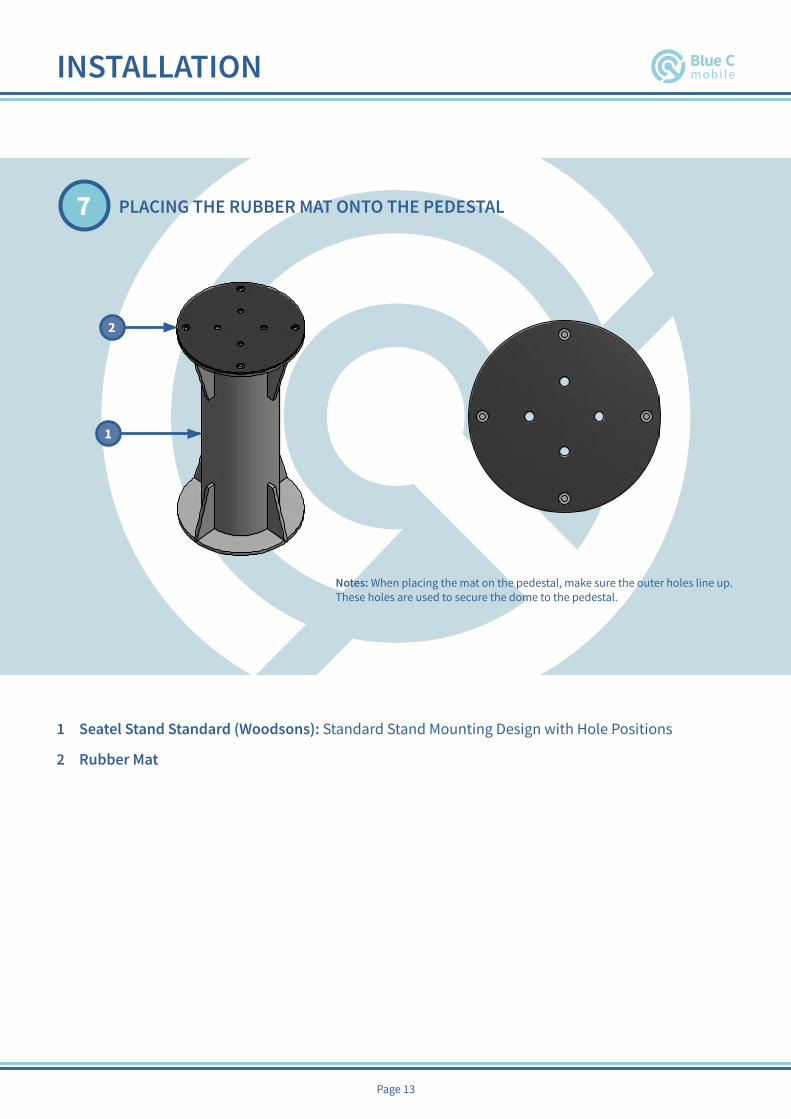
1 Seatel Stand Standard (Woodsons): Standard Stand Mounting Design with Hole Positions
2 Rubber Mat
PLACING THE RUBBER MAT ONTO THE PEDESTAL7
PARTS LISTDESCRIPTIONPART NUMBERQTYITEM
Standard Stand Mounting Design with Hole PositionsSeatel Stand Standard (Woodsons)11
Rubber Mat12
1
1
2
2
3
3
4
4
5
5
6
6
A A
B B
C C
D D
Hydra Install Manual
ManualGuideBlue C Mobile
21/05/2018Designed by Checked by Approved by Date
15 / 15 Edition Sheet
Date
2
1
Placing the Rubber Mat onto the Pedestal
Notes: When placing the mat on the pedestal, make sure the outer holes line up. These holes are used to secure the dome to the pedestal.
Notes: When placing the mat on the pedestal, make sure the outer holes line up. These holes are used to secure the dome to the pedestal.
1
2

INSTALLATION
Page 14
ATTACH DOME TO PEDESTAL AND ADDING LOCKTITE TO THE BOLTS8
F
PARTS LISTDESCRIPTIONPART NUMBERQTYITEM
M12 x 45 Hex BoltANSI B18.2.3.5M - M12 x 1.75 x 45
41
M12 Metric Plain WashersANSI B18.22M - 12 N42Locktite 13
F
1
1
2
2
3
3
4
4
5
5
6
6
A A
B B
C C
D D
Hydra Install Manual
ManualGuideBlue C Mobile
21/05/2018Designed by Checked by Approved by Date
6 / 9 Edition Sheet
Date
Securing the dome to the pedestal andadding locktite to the bolts.
1
2
F
3
Note: Making sure you place some locktite onto the end of each of the bolts before you place them throughthe pedestal and dome.
Securing the dome to the pedestal and adding locktite to the bolts. Note: Making sure you place some locktite onto the end of each of the bolts before you place them through the pedestal and dome.
2
1
F
3
F1 M12 x 45 Hex Bolt
2 M12 Metric Plain Washers
3 Bottle of Locktite

INSTALLATION
Page 15
SET UP AC – POWER CONNECTION WIRING9
AC CONNECTIONS
2
1
NEUTRAL
EARTH
LIVE
1 Power Connector
2 Core Power cable must conform to marine standards. A cable similar to MPRXCX 0.6/1 (1.2) kV 3G1.5 should be used. Please note that the below deck side of this wiring requires a plug that matches your ships standard AC power.
INSTALLATION
1 M12 x 45 Hex Bolt
2 M12 Metric Plain Washers
3 Bottle of Locktite

INSTALLATION
Page 16
SET UP ETHERNET CONNECTION WIRING10
PARTS LIST
DESCRIPTIONPART NUMBERQTYITEMEthernet ConnectorRDP-00AMMA-TLM700111ConnectorRJ4512
Cat5E cable must conform to marine standards. A cable similar to BC-10-021
Cabling13
1
1
2
2
3
3
4
4
5
5
6
6
A A
B B
C C
D D
Hydra Install Manual
ManualGuideBlue C Mobile
21/05/2018Designed by Checked by Approved by Date
14 / 14 Edition Sheet
Date
Ethernet Connection
1
2 7
8
Wiring Properties - Part BWiring Side A Wiring Side B Wiring Colour Wire Gauge
Pin 1 Pin 1 Orange White 24Pin 2 Pin 2 Orange 24Pin 3 Pin 3 Green White 24Pin 4 Pin 4 Blue 24Pin 5 Pin 5 Blue White 24Pin 6 Pin 6 Green 24Pin 7 Pin 7 Brown White 24Pin 8 Pin 8 Brown 24
1
3 2
Note: Please remember to put on the black cable mount before crimping the RJ45 connector.
IMAGE A shows the how the Cat5E cable will line up with the RJ45 connector. Make sure that you have placed the connector on before moving on to the crimping step.
IMAGE Bshowsthefinalproductfortheethernetconnectortotheantenna,seeninthediagramonpage 8 and tagged as number 2. Placing the wire through the connector before crimping.
231
1 Ethernet Connector
2 Cat5E cable must conform to marine standards. A cable similar to BC-10-021WIRING PROPERTIES - PART B
Wiring Side A Wiring Side B Wiring Colour Wire Gauge Pin 1 Pin 1 Orange White 24 Pin 2 Pin 2 Orange 24 Pin 3 Pin 3 Green White 24 Pin 4 Pin 4 Blue 24 Pin 5 Pin 5 Blue White 24 Pin 6 Pin 6 Green 24 Pin 7 Pin 7 Brown White 24 Pin 8 Pin 8 Brown 24
IMAGE A IMAGE B

INSTALLATION
Page 17
USE OF CRIMP TOOL11
Begin by stripping back one side of the Cat5E cable using the cable stripper part of the crimp tool (1). Your cable should look something like (2).
Unwind the individual wires and straighten them out, ready to be inserted into the RJ45 connector. Be sure to follow the color guide on previous page. You must make sure that all the wires are of the same length and that they are 13 mm long (12.7 mm to be precise). You can reduce the size of the wires using scissors or the cable cutter part of the crimp tool.
Carefully placing them into the connector, making sure they keep the same order and reach the end of the connector. Note that the connector must be the right way up, which can be seen on previous page.
You are now ready to crimp the connector and wiring into place. Insert the connector while holding the cabletothecrimppartofthecrimptool.Itshouldfitnicely.
Please repeat the same steps for the reversed side of the cable.
2
4
3
5
1
INSTALLATION

INSTALLATION
Page 18
CONNECT THE CONNECTORS12
1
1
2
2
3
3
4
4
5
5
6
6
A A
B B
C C
D D
Hydra Install Manual
ManualGuideBlue C Mobile
21/05/2018Designed by Checked by Approved by Date
8 / 9 Edition Sheet
Date
Connect the power and ethernet connectors to the antenna.
Notes:Make sure the cables hanging from the antenna are safely secured to either the pedestal so there are no hazards.
Connect the power and ethernet connectors to the antenna.
Notes: Make sure the cables hanging from the antenna are safely secured to either the pedestal so there are no hazards.

INSTALLATION
Page 19
CONNECT TO ANTENNA ETHERNET13
Antenna Ethernet connector provides internet connection & also access to antenna interface via web browser.
Antenna provides IP address via DHCP.
1
1
2
2
3
3
4
4
5
5
6
6
A A
B B
C C
D D
connectToLaptop
BlueCMobile 11/06/2018Designed by Checked by Approved by Date
1 / 2 Edition Sheet
Date
Option 1: Directly Connect to PC
Ethernet Connection
Notes: Connect your antenna straight to your laptop via ethernet connection.
1
1
2
2
3
3
4
4
5
5
6
6
A A
B B
C C
D D
connectToLaptop
BlueCMobile 11/06/2018Designed by Checked by Approved by Date
2 / 2 Edition Sheet
Date
Option 2: Connect to ships IT
Notes: Connect the antenna to your ships router or IT method through ethernet. From there you can either connect your laptop via wifi or ethernet connection.
Ethernet Connection
Option of ethernet connection or wifi
Option 1: Directly Connect to PC
Option 2: Connect to ships IT
Notes: Connect your antenna straight to your laptop via ethernet connection.
Notes: Connect the antenna to your ships router or IT method through ethernet. From there you can either connectyourlaptopviawifior ethernet connection.
INSTALLATION
Notes: Make sure the cables hanging from the antenna are safely secured to either the pedestal so there are no hazards.

INSTALLATION
Page 20
POWER THE ANTENNA 14
Now you may power up your antenna. Correct installation will result in the antenna searching and locking onto a satellite. Please visit 192.168.88.78 to view the antenna interface.
Antenna Interface
Antenna will search for correct satellite and lock automatically. Status can be seen on interface.
If you are not getting an internet connection, please check that you are not in the shadow of the mast.
Onfirstusethesystemmaytakesometime to download updates from the network. Allow for 30 minutes for the system to stabilise before usage.
2)
1)

FREE 100 MB DATA PACKAGE
Page 21
Enjoy your internet from Blue C Mobile.
Please could you use your tablet to take 6 pictures of your installation including a view towards the radar and bridge, and email to [email protected] also including the IMO of the ship.
In return we’ll credit you with 100 MB of data package for free!
CONGRATULATIONS ON MAKING YOUR SHIP BLUE C MOBILE READY!
FOR YOUR FREE 100MB DATA PACKAGE EMAIL US 6 PHOTOS OF YOUR INSTALLATION