Embed Size (px)
Citation preview
www.purelogic.ru
Moscow +7 (495) 505 63 74Voronezh +7 (473) 204 51 56
Contacts:
149 Office160, Leninsky avenueVoronezh, Russia, 394033
Monday - Thursday: 8.00–17:00Friday: 8.00–16.00Break: 12.30–13.30
01. Summarize02. System board and main interface03. Cutting function04. Part options 05. Manual function06. File operation07. Parameter setting08. Diagnosis function 09. Graph 10. Port explanation11. Installation and debugging12. The use of bios 13. G, M code rapid consult
INSTRUCTION MANUAL24714242630374244575859
HYD-2300CNC Plasma&Flame Cutting Control System
We draw your attention to the fact that there can be some changes in this instruction due to the product consistent technical improvement.

HYD-2100. CNC Plasma&Flame Cutting Control System
Edition of 28.07.2015 2www.purelogic.ru8 (800) 555 63 74
01 Summarize
BRIEF INTRODUCTION
The digital controller 2300 is a new production, which is integrated many merits of the same productions at home and aboard. The controller can control the motion of two axis, which is apt to the application of flame or plasma cutting. This controller is very light and handy and it is very easy to operate. The controller provides menu or illustration for all the operations for the convenience of users. All key switches are human oriented designed, and they are very convenient and comfortable.The controller chooses high speed DSP and ARM as its core to assure the cutting process to be more stable. The motion control algorithm is optimized so that the machine can move more stale and reliable, and it can save the life of the motor and the mechanical parts.
CHARACTERISTICS OF SYSTEM
1) 10.4 inches 800*680 dots color LCD.Man-Machine-Dialog software and Professional Hot Key design for easy cutting operation, user-friendly as Hypertherm’s EDGE controller.2) Multi-language file system and menu, and the menu can be switched only by one key.3) DSP core can control the machine move in high speed accurately, stably and in low noise.4) Long-distance remote control can control the machine to move forward ,backward, left, right and cutting start, stop and so on (optional configuration).5) Support the EIA code (G code) and various FastCAM, FreeNest, SmartNest, IBE softwares.6) compact keyboard design and easy to input files.7) Operations such as Proportion Zoom, Rotate, Mirror, Array display, Steel plate angle adjust…..all available and have professional solution in the CNC controller. 8) Coordinate system can be customized to support the two-dimensional coordinates of all eight kinds.9) All input and output port type and the number can be customized (normally open or normally closed)10) System Self-diagnosis for easy trouble-shooting.11) All functions and techniques can upgrade online.12) Import and export files by single or all files.13) Support the Flame, Plasma, Dusting draw and Demonstration four kinds of mode.14) Flame and Plasma are separated in the control IO ports.15) Support THC, two level preheat, three level pierce in flame mode.16) Plasma arc feedback, positioning feedback, automatically shut down the arc at the corner.17) Support edge cutting. It can save the preheat time for the thick steel plate.18) Movement speed can be real-time acceleration, deceleration.19) According to plate thickness, the cutting speed is automatically restricted by a speed limit in the corner, effectively preventing over burn.

HYD-2100. CNC Plasma&Flame Cutting Control System
Edition of 28.07.2015 3www.purelogic.ru8 (800) 555 63 74
20) Dynamic/static illustration of the process, graphics zoom in / out, dynamically tracking cut-off point under zooming state.21) Automatically memorize the working situation and the last cutting point when power off.22) «Cutting offset» function can avoid waste the steel plate when the nesting of the plate is calculated wrong.23) Set up different administration authority and the corresponding password to safeguard the interests of managers.
TECHNICAL STANDARD
1) Control Axis: 22) Control accuracy: +/-0.001mm3) Coordinate range: +/- 99999.999mm4) Max pulses : 200kHz Max speed: 15000 mm/m5) Max lines of code: 150000 lines6) Max size of single code file: 4M 7) Time resolution: 10ms8) Working Voltage: DC 24V in put9) Working Temperature: -10 — 60 °C. Relative Humidity, 0-95%.
SYSTEM INTERFACE
1) 15 pins interface of 2 axis of motor drive.2) 25 pins interface of 16 channels optical couple output ports, max back flow current 300mA.3) 25 pins interface of 16 channels optical couple input ports, max output current 300mA.4) USB interface on the front panel.5) Extend IO input/output ports, PWM input ports, analog input ports.
HARDWARE CONFIGURATION
1) Monitor:15 inch, 1024*768, high definition 16 million colors and high brightness LCD or 10.4 inch 800*600, 26 million color LCD.2) Memory: 64M SDRAM.3) Memory available for user: 256M or 1G electronic hard disk.4) System master frequency: 400MHz.5) USB: USB 1.1 front interface.6) Keyboard: electronic PCB foil keyboard (one machine) or standard industrial keyboard (split type machine).7) Chassis: full-steel structure completely shielded which defends electromagnetic radiation, interference and static electricity.

HYD-2100. CNC Plasma&Flame Cutting Control System
Edition of 28.07.2015 4www.purelogic.ru8 (800) 555 63 74
02 System board and main interface
INTRODUCTION OF OPERATING BOARD
[F1] - [F8]: Function key in different interface.[S↑/PgUP]: Page-up key of code interface or Torch up in other interface.[S↓/PgDn]: page-down key of code interface or Torch down in other interface.[F+/HOME]: Accelerate or skip to the head of code line.[F-/END]: Decelerate or skip to the tail of code line.[1]-[9]: during the cutting process, change the cutting speed to ratio of the speed limit you have set, for example press [1], change the cutting speed to 10% of the speed limit you have set, press [2], change the cutting speed to 20% of the speed limit you have set.
Figure 1. Board and keys
Figure 2. System self scan
POWER ON PROCESS AND MAIN INTERFACE
When power just on, the system will go for the process of self scan:
In the starting process, there is 3 seconds to countdown, before the countdown is over, if pressing [F2], it will enter the bios starting interface shown as Fig. 3 (please take the reference of the appendix 2 to run bios). If pressing any other key, it will jump over the countdown and directly enter the welcome interface. If pressing no key, it will countdown to 0 and then enter the welcome interface shown as Fig. 4. In the welcome interface, press any key to enter the main interface automatically shown as Fig. 5.

HYD-2100. CNC Plasma&Flame Cutting Control System
Edition of 28.07.2015 5www.purelogic.ru8 (800) 555 63 74
F1 ShapeLib F2 FilesF3
PartOptionF4 Setups F5 Diagnose F6 ZoomIn
F7 ManualMove
F8 Zero
FLSK F2500Version 3.3.71.1
Speed:00000
File:SHAPE_43.TXT
Status: Current Line/Hole:00000/00000
+X:500.00 -X:0.00 +Y:500.00 -Y:0.00
00001:(TEST PATTERN)00002:G92
●Ignition s●LowPreheat s●HighPreheat s●Pierce 1 s●Pierce 2 s●Pierce 3 s●TorchUp s●TorchDn s●THC En s●Exhaust s
Manual 【F】keepMov StepMov ContiMovStepDis【G】 5.00 Flame Cu 【G】
CutSpeed 【X】1000.00 Kerf【Z】1.20ManualSpeed【Y】3000.00 Angle 0.00
Figure 3. Bios interface
Figure 5. The main interface
Figure 4. Welcome interface
In the main interface, press [F1]-[F8] for the following functions:[F1] ShapeLib: pressing F1 to enter the Shape Library including 45 common shape, and most of them have plate size and hole size.[F2] Files: You can load local files, U disk files or edit, import, export and delete codes.[F3] PartOption: make actions of mirroring, rotation, plate adjusting, plate arraying, selecting row and hole or code edition etc.[F4] Setups: setting all parameters.[F5] Diagnose: including input ports diagnosis, output ports diagnosis, keyboard diagnosis, system self check, date setting and system self defines.
F1 - System software updateF2 - Welcome picture updateF3 - Motion updateF4 - System backupF5 - System recoveryF6 - Start system

HYD-2100. CNC Plasma&Flame Cutting Control System
Edition of 28.07.2015 6www.purelogic.ru8 (800) 555 63 74
[F6] ZoomIn: Zoom in the shape in full screen.[F7] ManualMove: Manually move the machine.[F8] Zero: Clear the coordinate of X and Y before starting cut or after cutting over.[X] CutSpeed: Setting the cutting speed.[Y] ManualSpeed: Setting the manual moving speed.[Z] Kerf: Setting the kerfs’ compensate value.[F] Manual: Setting the mode of manual movement including keepMov (keep movement), StepMov (step movement), ContiMov (continue movement). The selected mode is black background.[G] StepDis: Setting the distance of the fixed-length.[M] Selecting the cutting mode including Flame Cu (flame cutting), Plasma C (plasma cutting), Demo run.
FUNCTION INDEX OF MAIN INTERFACE
Main Interface
F1ShapeLib
F4Setups
F5Diagnose
F6Zoom In
F7Manual Move
F8Zero
F2Files
F3Part
Option
F8OK
F1Disk File
F2U Disk
F3Search
F4Edit File
F5Del File
F6Copy to U
F7Preview
F8OK
F1Mirror
F2Angle
F3Array
F4Scale
F5Select
line and pierce
F7Revert
F8OK
F1common
F2Flame
F3Plasma
F4Powder
F5System
F6Import
Parameters
F7Export
Parameters
F8Save
F1Input
Diagnose
F2Output
Diagnose
F3Open
Output
F4CloseOutput
F5Keyboard Diagnose
F6System
Self-check
F7Date time
F8System
Definition
F1keep
moving
F2continue moving
F3step
moving
F4Speed-Down
F5Speed
accelaration
F7Recovery
F1Parameter Recovery
F1Input
F2Output
F3Coordinate
F8Save
F2Parameter
Backup
F3Definition
F4Encryption
F5Decryption
F6Language
F8 Update

HYD-2100. CNC Plasma&Flame Cutting Control System
Edition of 28.07.2015 7www.purelogic.ru8 (800) 555 63 74
03 Cutting function
In the main interface, press the [SPACE] to enter the cutting interface, shown as follows.
Show the current workpiece’s cutting path, including the slotted value.Show the G-code being processed, shows the current and next line.Show the current cutting speed, during processing, you can press the keyboard’s number keys.
[1] - [9] to achieve quick speed regulation. For example, press the number [3], the speedis automatically adjusted to 30%; press the number ]8] the speed is automatically adjusted to80%.X shows the absolute coordinate of the torch in X direction.Y shows the absolute coordinate of the torch in Y direction.
In the cutting interface:• Press [X]: Modify the current maximum cutting speed.• Press [Y]: Modify the current maximum speed manual shift car.• Press [F]: Change the current manual method.• Press [G]: Modify the current fixed-length fixed long-distance move.• [START] ([F9]): Start cutting.
Figure 6. Сutting function interface
F1 Back F2 Forward F3 GoBackF4
SpeedDownF5 SpeedUp
F6 PreheatDown
F7 PreheatUp
F8 JumptoPierce
FLSK F2500Version 3.3.71.1
Speed:00000
File:SHAPE_43.TXT
Status: Current Line/Hole:00000/00000
+X:500.00 -X:0.00 +Y:500.00 -Y:0.00
00001:(TEST PATTERN)00002:G92
●Ignition s●LowPreheat s●HighPreheat s●Pierce 1 s●Pierce 2 s●Pierce 3 s●TorchUp s●TorchDn s●THC En s●Exhaust s
Manual 【F】keepMov StepMov ContiMovStepDis【G】 5.00 Flame Cu 【G】
CutSpeed 【X】1000.00 Kerf【Z】1.20ManualSpeed【Y】3000.00 Angle 0.00
3
1
2
HYD-2100. CNC Plasma&Flame Cutting Control System
Edition of 28.07.2015 8www.purelogic.ru8 (800) 555 63 74
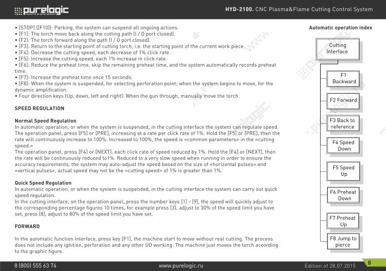
• [STOP] ([F10]): Parking, the system can suspend all ongoing actions.• [F1]: The torch move back along the cutting path (I / O port closed). • [F2]: The torch forward along the path (I / O port closed).• [F3]: Return to the starting point of cutting torch, i.e. the starting point of the current work piece.• [F4]: Decrease the cutting speed, each decrease of 1% click rate.• [F5]: Increase the cutting speed, each 1% increase in click rate.• [F6]: Reduce the preheat time, skip the remaining preheat time, and the system automatically records preheat time.• [F7]: Increase the preheat time once 15 seconds.• [F8]: When the system is suspended, for selecting perforation point; when the system begins to move, for the dynamic amplification.• Four direction keys (Up, down, left and right): When the gun through, manually move the torch.
SPEED REGULATION
Normal Speed RegulationIn automatic operation, or when the system is suspended, in the cutting interface the system can regulate speed.The operation panel, press [F5] or [PRE], increasing at a rate per click rate of 1%. Hold the [F5] or [PRE], then the rate will continuously increase to 100%. Increased to 100%, the speed is «common parameters» in the «cutting speed.»The operation panel, press [F4] or [NEXT], each click rate of speed reduced by 1%. Hold the [F4] or [NEXT], then the rate will be continuously reduced to1%. Reduced to a very slow speed when running in order to ensure the accuracy requirements, the system may auto-adjust the speed based on the size of «horizontal pulses» and «vertical pulses», actual speed may not be the «cutting speed» of 1% is greater than 1%.
Quick Speed RegulationIn automatic operation, or when the system is suspended, in the cutting interface the system can carry out quick speed regulation.In the cutting interface, on the operation panel, press the number keys [1] - [9], the speed will quickly adjust to the corresponding percentage figures 10 times, for example press [3], adjust to 30% of the speed limit you have set, press [8], adjust to 80% of the speed limit you have set.
FORWARD
In the automatic function interface, press key [F1], the machine start to move without real cutting. The process does not include any ignition, perforation and any other I/O working. The machine just moves the torch according to the graphic figure.
Automatic operation index
Cutting Interface
F1 Backward
F2 Forward
F3 Back to reference
F4 Speed Down
F8 Jump to pierce
F5 Speed Up
F6 Preheat Down
F7 Preheat Up

HYD-2100. CNC Plasma&Flame Cutting Control System
Edition of 28.07.2015 9www.purelogic.ru8 (800) 555 63 74
The function can be used to check the trail and code before you start the real cutting process, or can also be used when the process needs through the gun. Press the red “STOP” key to stop the null cutting process if you want.
BACKWARD
During the running process, if you want to go backward according to the origin trail to (maybe the iron board was not cut through), you can follow the following direction:• First, press “STOP” key to set the machine at pause status.• In the automatic function interface, press key [F3] (Back) to make the machine go backward along with the original trail. When the torch reaches the position you need, press “STOP” key to stop it. You may press key [F2] to go forward if the machine just went back too much.Notice: Go backward or forward function can be used repeatedly to make the machine reach an ideal position.• When the torch reaches the position you need, press “START” key again, if the current cutting code is G01, G02 or G03, system will automatically perforate before performing these procedures, and then continue the current program, if the current row is not G01, G02 or G03, the system will directly continue the current line program.
EDGE CUTTING / OFFSET CUTTING / RETURN
When the torch is not on the actual path of the current work piece, it will prompt as follows.
There are two reasons led to this situation:1) When the common parameter «edge perforation» selects «Yes» and the next processing line G-code is M07, the system will be automatically suspended. At this time, the torch can be manually moved to any edge of the plate, press the «start» button, the system will prompt as above.2) When the processing is paused, due to mechanical failure or other reasons, it needs to move the torch out of the actual path of the workpiece, the above prompt will appear. move the torch out of the actual path of the workpiece, the above prompt will appear.• If press [G], the system cutting returns back to the paused point, continue to cut it. This feature is particularly useful for thick steel plate, it can reduce
F1 Back F2 Forward F3 GoBackF4
SpeedDownF5 SpeedUp
F6 PreheatDown
F7 PreheatUp
F8 JumptoPierce
FLSK F2500Version 3.3.71.1
Speed:00000
File:SHAPE_43.TXT
Status:Pause
Current Line/Hole:00000/00000
+X:500.00 -X:0.00 +Y:500.00 -Y:0.00
00001:(TEST PATTERN)00002:G92
●Ignition s●Lowheat s●HighPreheat s●Pierce 1 s●Pierce 2 s●Pierce 3 0.1 s●TorchUp s●TorchDn s●THC En s●Exhaust s
Manual 【F】keepMov StepMov ContiMovStepDis【G】 5.00 Flame Cu 【M】
CutSpeed 【X】1000.00 Kerf【Z】1.20ManualSpeed【Y】3000.00 Angle 0.00
[G]Cutting return[X]Offset cutting[Y]only return
Figure 7. Edge perforation

HYD-2100. CNC Plasma&Flame Cutting Control System
Edition of 28.07.2015 10www.purelogic.ru8 (800) 555 63 74
the preheat time and increase cutting efficiency. This function is the commonly-used edge perforation function.• If press [X], the system considers current point is the paused point, it will continue cutting it. That is, the system offsets the cutting point. When the cutting machine paused or a power outage, if the cutting tip or steel plate with the pan has been offset, or the user would like to think that is offset cutting, you can press this button.• If press [Y], The system only return to the paused point quickly, and then break off. During the cutting process, if discovery cutting torch malfunction, or other issues, need to move the cutting tip out of cutting region to overhaul. After the maintenance, this key can be pressed. Then return to the paused point, press the «start» button, the system automatically continues to cutting.
BACK TO REFERENCE FUNCTION
Pause in the processing, if press the [F3], then the system will prompt.
Press the Enter key, the system will automatically return to the starting point of the work piece, and then the system automatically switches to processing the main interface, and waits for further user action.
F1 Back F2 Forward F3 GoBackF4
SpeedDownF5 SpeedUp
F6 PreheatDown
F7 PreheatUp
F8 JumptoPierce
FLSK F2500Version 3.3.71.1
Speed:00000
File:SHAPE_43.TXT
Status:Pause
Current Line/Hole:00000/00000
+X:500.00 -X:0.00 +Y:500.00 -Y:0.00
00001:(TEST PATTERN)00002:G92
●Ignition s●Lowheat s●HighPreheat s●Pierce 1 s●Pierce 2 s●Pierce 3 0.1 s●TorchUp s●TorchDn s●THC En s●Exhaust s
Manual 【F】keepMov StepMov ContiMovStepDis【G】 5.00 Flame Cu 【M】
CutSpeed 【X】1000.00 Kerf【Z】1.20ManualSpeed【Y】3000.00 Angle 0.00
Are you sure to return?
ENTER: Sure ESC: Cancel
Figure 8. Return reference prompt

HYD-2100. CNC Plasma&Flame Cutting Control System
Edition of 28.07.2015 11www.purelogic.ru8 (800) 555 63 74
F1 ShapeLib F2 FilesF3
PartOptionF4 Setups F5 Diagnose F6 ZoonIn
F7 ManualMove
F8 Zero
FLSK F2500Version 3.3.71.1
Speed:00000
File:SHAPE_43.TXT
Status:Stop
Current Line/Hole:00000/00000
+X:500.00 -X:0.00 +Y:500.00 -Y:0.00
00001:(TEST PATTERN)00002:G92
●Ignition s●Lowheat s●HighPreheat s●Pierce 1 s●Pierce 2 s●Pierce 3 0.1 s●TorchUp s●TorchDn s●THC En s●Exhaust s
Manual 【F】keepMov StepMov ContiMovStepDis【G】 5.00 Flame Cu 【M】
CutSpeed 【X】1000.00 Kerf【Z】1.20ManualSpeed【Y】3000.00 Angle 0.00
Figure 9. Main process interface
During the return process, the user can press the «Stop» button to stop the operation, and can continue to return operation after pressing of [F3]. Number of back to reference and stop has no limit.
OXYGEN GAS PREHEAT TIME REGULATION
• In the preheat process, press the START (F9) key to skip the process of preheat and perforation delay, and immediately open the perforation signal then begin to cut.• In the preheat process, press the stop (F10) key to stop preheat, waiting for the F9 key is pressed again.• In the preheat process, press the F6 key then the preheat time will be reduced to the current preheat time spent, and skip the process of preheat and perforation delay, and open the perforation signal then begin to cut. For example: the original system sets the preheat time of 60 seconds after null cutting, when preheat needed, the interface will count down, under normal circumstances, till 0, the system begins the next step of cutting, but if the system has the remaining 10 seconds of countdown time, press F6, then the system immediately stops preheat to begin the next step of cutting, and records the preheat time of 50 seconds, the system automatically thinks that users need preheat time of 50 seconds, the next preheat after the null cutting when the preheat time becomes 50 seconds.• In the preheat process, each press the F7 key, preheat time increases by 15 seconds, and the preheat time maintains the increased value. For example: The original system sets the preheat time of 60 seconds after the null cutting, during the system countdown, each press F7, on the interface the countdown increases by 15 seconds, and the next time you need to preheat, the initial preheat time be 75 seconds.
PERFORATION POINT SELECTION
HYD-2100. CNC Plasma&Flame Cutting Control System
Edition of 28.07.2015 12www.purelogic.ru8 (800) 555 63 74
F1 Back F2 Forward F3 GoBackF4
SpeedDownF5 SpeedUp
F6 PreheatDown
F7 PreheatUp
F8 JumptoPierce
FLSK F2500Version 3.3.71.1
Speed:00000
File:SHAPE_43.TXT
Status:Pause
Current Line/Hole:00000/00000
+X:500.00 -X:0.00 +Y:500.00 -Y:0.00
00006: G01 X0 Y500.0000007:G01 X500.00 Y0
●Ignition s●Lowheat s●HighPreheat s●Pierce 1 s●Pierce 2 s●Pierce 3 0.1 s●TorchUp s●TorchDn s●THC En s●Exhaust s
Manual 【F】keepMov StepMov ContiMovStepDis【G】 5.00 Flame Cu 【M】
CutSpeed 【X】1000.00 Kerf【Z】1.20ManualSpeed【Y】3000.00 Angle 0.00
Jump to new pierce?
ENTER: Sure ESC: Cancel
F1 Mirror F2 Angle F3 Array F4 ScaleF5
SelLinePierceF6 EditFile F7 Revert F8 OK
FLSK F2500Version 3.3.71.1
Speed:00000
File:SHAPE_43.TXT
Status:Pause
Current Line/Hole:00000/00000
+X:500.00 -X:0.00 +Y:500.00 -Y:0.00
00006: G01 X0 Y500.0000007:G01 X500.00 Y0
●Ignition s●Lowheat s●HighPreheat s●Pierce 1 s●Pierce 2 s●Pierce 3 0.1 s●TorchUp s●TorchDn s●THC En s●Exhaust s
Manual 【F】keepMov StepMov ContiMovStepDis【G】 5.00 Flame Cu 【M】
CutSpeed 【X】1000.00 Kerf【Z】1.20ManualSpeed【Y】3000.00 Angle 0.00
Input No. of pierces:Press <- -> select No. of pierce0
F8:OK
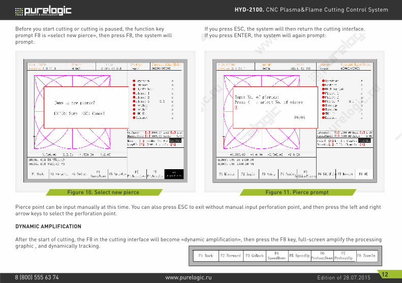
Figure 10. Select new pierce Figure 11. Pierce prompt
Before you start cutting or cutting is paused, the function key prompt F8 is «select new pierce», then press F8, the system will prompt:
Pierce point can be input manually at this time. You can also press ESC to exit without manual input perforation point, and then press the left and right arrow keys to select the perforation point.
DYNAMIC AMPLIFICATION
After the start of cutting, the F8 in the cutting interface will become «dynamic amplification», then press the F8 key, full-screen amplify the processing graphic , and dynamically tracking.
If you press ESC, the system will then return the cutting interface. If you press ENTER, the system will again prompt:

HYD-2100. CNC Plasma&Flame Cutting Control System
Edition of 28.07.2015 13www.purelogic.ru8 (800) 555 63 74
• Press the F8 key continuously, the system will progressively amplify graphic.• Press ESC to exit the amplified display, back to the cutting interface.
CUTTING EXIT
When the cutting operation does not get finished, and the cutting machine also being in the pause condition, if press [Esc], the system will query whether quit the cutting operation. If pressing [Enter], the system will exit, and if pressing [Esc] the system will not exit, get into the automatically interface and go on with the cutting operation at the current place.
F1 Back F2 Forward F3 GoBackF4
SpeedDownF5 SpeedUp
F6 PreheatDown
F7 PreheatUp
F8 JumptoPierce
FLSK F2500Version 3.3.71.1
Speed:00000
File:SHAPE_43.TXT
Status:Pause
Current Line/Hole:00000/00000
+X:500.00 -X:0.00 +Y:500.00 -Y:0.00
00006: G01 X0 Y500.0000007:G01 X500.00 Y0
●Ignition s●Lowheat s●HighPreheat s●Pierce 1 s●Pierce 2 s●Pierce 3 0.1 s●TorchUp s●TorchDn s●THC En s●Exhaust s
Manual 【F】keepMov StepMov ContiMovStepDis【G】 5.00 Flame Cu 【M】
CutSpeed 【X】1000.00 Kerf【Z】1.20ManualSpeed【Y】3000.00 Angle 0.00
Quit of cutting?
ENTER: QuitESC: Continue cutting
Figure 12. Quit of cutting

HYD-2100. CNC Plasma&Flame Cutting Control System
Edition of 28.07.2015 14www.purelogic.ru8 (800) 555 63 74
04 Part options
XY MIRROR
Press F1, the system will prompt:
• Press F1 to mirror along the horizontal axis (X axis).• Press F2 to mirror along the vertical axis (Y axis). • Press ESC to exit mirror operation.
ANGLE ADJUSTMENT
Press F2, the system will prompt:
• Press F1 to adjust steel plate.• Press F2 to enter angle directly.• Press ESC to exit angle adjusting.
F1- Steel plate adjustF2- enter angle
Figure 13. Part options
F1 Mirror F2 Angle F3 Array F4 ScaleF5
SelLinePierceF6 EditFile F7 Revert F8 OK
FLSK F2500Version 3.3.71.1
Speed:00000
File:SHAPE_43.TXT
Status:Pause
Current Line/Hole:00000/00000
+X:500.00 -X:0.00 +Y:500.00 -Y:0.00
Operate Mode:PartOption
●Ignition s●Lowheat s●HighPreheat s●Pierce 1 s●Pierce 2 s●Pierce 3 0.1 s●TorchUp s●TorchDn s●THC En s●Exhaust s
Manual 【F】keepMov StepMov ContiMovStepDis【G】 5.00 Flame Cu 【M】
CutSpeed 【X】1000.00 Kerf【Z】1.20ManualSpeed【Y】3000.00 Angle 0.00

HYD-2100. CNC Plasma&Flame Cutting Control System
Edition of 28.07.2015 15www.purelogic.ru8 (800) 555 63 74
STEEL PLATE ADJUSTMENT
After entering steel plate adjustment menu, the system will prompt:
Here, you can manually move the cutting tip to the edge of one side or a corner of the plate. When the cutting tip moved to a good position, press [X] key to set the current point as the starting point of correction.And then manually move along the cutting tip, as long as moving to the edges of the side. After ensuring the two points far enough and two points at the same side of the plate in the same line and press [Y]. The system will automatically calculate the current offset angle of plate, and then automatically rotate graphics.
After adjusting, the system will ask whether to return to the start point, if press [ENTER],the system will back to the start point of the operation, if press [ESC], the system will do nothing but go back to the graphic interface.
X-start Y-OK ESC-exitAdjust X: +00000.00Adjust Y: +00000.00Angle: +00000.00
Figure 14. Before adjusting Figure 15. After adjusting

HYD-2100. CNC Plasma&Flame Cutting Control System
Edition of 28.07.2015 16www.purelogic.ru8 (800) 555 63 74
Figure 16. Return to the start point after adjusting
F1 Mirror F2 Angle F3 Array F4 ScaleF5
SelLinePierceF6 EditFile F7 Revert F8 OK
FLSK F2500Version 3.3.71.1
Speed:00000
File:SHAPE_43.TXT
Status:Pause
Current Line/Hole:00000/00000
+X:500.00 -X:0.00 +Y:500.00 -Y:0.00
00006: G01 X0 Y500.0000007:G01 X500.00 Y0
●Ignition s●Lowheat s●HighPreheat s●Pierce 1 s●Pierce 2 s●Pierce 3 0.1 s●TorchUp s●TorchDn s●THC En s●Exhaust s
Manual 【F】keepMov StepMov ContiMovStepDis【G】 5.00 Flame Cu 【M】
CutSpeed 【X】1000.00 Kerf【Z】1.20ManualSpeed【Y】3000.00 Angle 0.00
ENTER: Return backESC: Don’t move back
ENTER ANGLE
When the angle of the current work piece is known, you can enter the angle:
After manually enter the angle, press [ENTER] to make sure, the graphic will be rotate with the corresponding angle. Positive angle means rotate in counterclockwise, while negative means clockwise. Press [ESC] to exit angle adjusting.
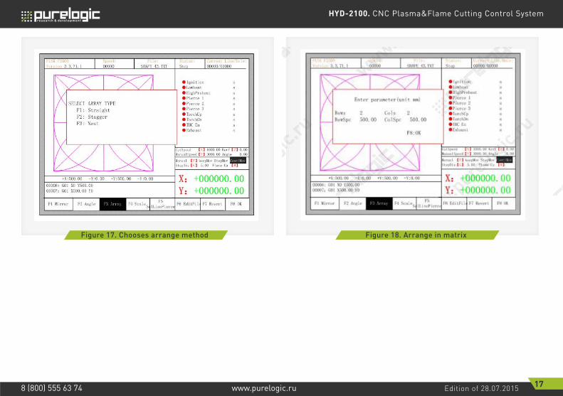
ARRAY
In the part options menu, press [F3], the system will prompt as Fig. 17, there are three ways to arrange, arrange in matrix, staggered arrange, arrange in stack.
Please enter anglemin: -360 max: 360Angle: 0.00
HYD-2100. CNC Plasma&Flame Cutting Control System
Edition of 28.07.2015 17www.purelogic.ru8 (800) 555 63 74
Figure 17. Chooses arrange method Figure 18. Arrange in matrix

HYD-2100. CNC Plasma&Flame Cutting Control System
Edition of 28.07.2015 18www.purelogic.ru8 (800) 555 63 74
Figure 19. Result of arranging in matrix Figure 20. Staggered arrange
Press [F1] to carry on arranging in matrix. The result is shown in fig. 19.
HYD-2100. CNC Plasma&Flame Cutting Control System
Edition of 28.07.2015 19www.purelogic.ru8 (800) 555 63 74
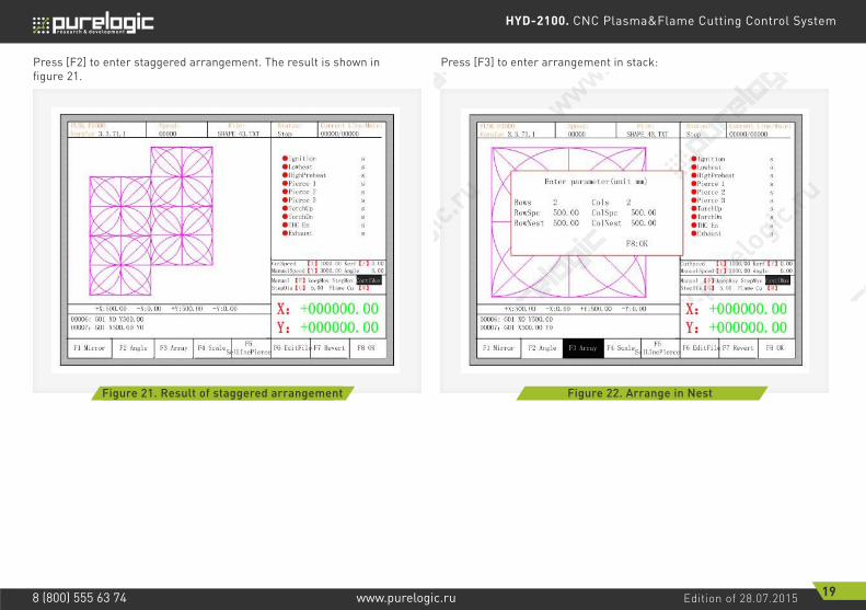
Figure 21. Result of staggered arrangement Figure 22. Arrange in Nest
Press [F2] to enter staggered arrangement. The result is shown in figure 21.
Press [F3] to enter arrangement in stack:

HYD-2100. CNC Plasma&Flame Cutting Control System
Edition of 28.07.2015 20www.purelogic.ru8 (800) 555 63 74
Figure 23. Result of arrangement in nest
Figure 24. Set scale
ZOOM IN/OUT
In the part options menu, press [F4] (zoom in/out),the system prompt as figure 24. After entering the scale, press [Enter], then the system will automatically zoom in or zoom out the graphic when the parameter is checked to be correct.
The result is shown in figure 23.

HYD-2100. CNC Plasma&Flame Cutting Control System
Edition of 28.07.2015 21www.purelogic.ru8 (800) 555 63 74
Figure 25. Set scale Figure 26. Select Line/Pierce
Select row/numberIn part options menu, press [F5]to enter selecting row/number, the system will prompt:
Select rowPress [F1] to select the number of row to start cutting with, the system prompts:

HYD-2100. CNC Plasma&Flame Cutting Control System
Edition of 28.07.2015 22www.purelogic.ru8 (800) 555 63 74
Figure 27. Prompt to select row Figure 28. Select row
Select rowPress [F1] to select the number of row to start cutting with, the system prompts:
After selecting row, press F8 to confirm.
SELECT NUMBER
The operation is similar to the choosing row operation.
OPERATION AFTER SELECT ROW/NUMBER
After selecting row or number, press F8 continuously to exit to the main interface.
Here , you can directly enter the row number or press ENTER to enter the interface and press ←or→ to select row.

HYD-2100. CNC Plasma&Flame Cutting Control System
Edition of 28.07.2015 23www.purelogic.ru8 (800) 555 63 74
Press SPACE to enter the cutting interface, there are two kind of operation:1. Move from current position to the new position and then cutting• Press F1 in the cutting interface, the system will directly run to the position of the selected row or number without cutting, then pause and wait for the next operation.
Press Y , the system will also directly move to the selected row and number, then pause and wait for the next operation. 2. Cutting from the current position.After the prompt of Fig 4.14, press X, then the system will start cutting from current position.
RESTORE
If you want to cancel all of operations with graphics including mirror, rotation, adjust, scale and array, press [F7] in the part options menu, the system automatically revert to original state of the graphics.
Figure 29. Operation after selecting row/number

HYD-2100. CNC Plasma&Flame Cutting Control System
Edition of 28.07.2015 24www.purelogic.ru8 (800) 555 63 74
05 Manual function
In the automatic interface, press [F7] (Manual) to enter manual function interface, shown as Fig. 30.
The speed in the manual status is controlled by the manual moving parameters. During the process of fixed moving function, you can adjust speed by acceleration or deceleration key. In the manual interface, press numeric key, the cutting speed changes to ratio which is 10 times of the corresponding figure of the speed limit you have set, for example press [3], change the cutting speed to 30% of the speed limit you have set, press [8], change the cutting speed to 80% of the speed limit you have set.
FIXED MOVING FUNCTION
When you enter into the manual interface, the default option is continuous moving function.Press key [F1] to go for the fixed moving function. At this moment, the system will move toward the specified direction if any directory key is pressed, and when the directory key is released, the system will stop.
CONTINUOUS MOVING FUNCTION
When in the manual interface, press F2 to enter the continuous-moving function interface. At this moment, the system will move toward the specified direction if any directory key is pressed and then released, and when the directory key or stop key is pressed the system will stop.
Figure 30. Manual function interface
F1 Mirror F2 Angle F3 Array F4 ScaleF5
SelLinePierceF6 EditFile F7 Revert F8 OK
FLSK F2500Version 3.3.71.1
Speed:00000
File:SHAPE_43.TXT
Status:Pause
Current Line/Hole:00000/00000
+X:500.00 -X:0.00 +Y:500.00 -Y:0.00
Operate Mode:PartOption
●Ignition s●Lowheat s●HighPreheat s●Pierce 1 s●Pierce 2 s●Pierce 3 0.1 s●TorchUp s●TorchDn s●THC En s●Exhaust s
Manual 【F】keepMov StepMov ContiMovStepDis【G】 5.00 Flame Cu 【M】
CutSpeed 【X】1000.00 Kerf【Z】1.20ManualSpeed【Y】3000.00 Angle 0.00
HYD-2100. CNC Plasma&Flame Cutting Control System
Edition of 28.07.2015 25www.purelogic.ru8 (800) 555 63 74
F1 KeepMovF2
ContiMoveF3 StepMove
F4 SpeedDown
F5 SpeedUpF7
Recover
FLSK F2500Version 3.3.71.1
Speed:00000
File:SHAPE_43.TXT
Status:Stop
Current Line/Hole:00000/00000
+X:500.00 -X:0.00 +Y:500.00 -Y:0.00
00001: (TEST PATTERN)00002:G92
●Ignition s●Lowheat s●HighPreheat s●Pierce 1 s●Pierce 2 s●Pierce 3 s●TorchUp s●TorchDn s●THC En s●Exhaust s
Manual 【F】keepMov StepMov ContiMovStepDis【G】 5.00 Flame Cu 【M】
CutSpeed 【X】1000.00 Kerf【Z】0.00ManualSpeed【Y】3000.00 Angle 0.00
Input the step distance
5.00
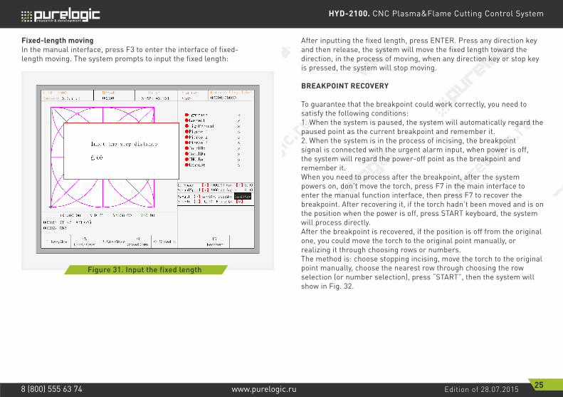
Figure 31. Input the fixed length
Fixed-length movingIn the manual interface, press F3 to enter the interface of fixed-length moving. The system prompts to input the fixed length:
After inputting the fixed length, press ENTER. Press any direction key and then release, the system will move the fixed length toward the direction, in the process of moving, when any direction key or stop key is pressed, the system will stop moving.
BREAKPOINT RECOVERY
To guarantee that the breakpoint could work correctly, you need to satisfy the following conditions:1. When the system is paused, the system will automatically regard the paused point as the current breakpoint and remember it. 2. When the system is in the process of incising, the breakpoint signal is connected with the urgent alarm input, when power is off, the system will regard the power-off point as the breakpoint and remember it.When you need to process after the breakpoint, after the system powers on, don’t move the torch, press F7 in the main interface to enter the manual function interface, then press F7 to recover the breakpoint. After recovering it, if the torch hadn’t been moved and is on the position when the power is off, press START keyboard, the system will process directly.After the breakpoint is recovered, if the position is off from the original one, you could move the torch to the original point manually, or realizing it through choosing rows or numbers. The method is: choose stopping incising, move the torch to the original point manually, choose the nearest row through choosing the rowselection (or number selection), press “START”, then the system will show in Fig. 32.

HYD-2100. CNC Plasma&Flame Cutting Control System
Edition of 28.07.2015 26www.purelogic.ru8 (800) 555 63 74
F1 Back F2 Forward F3 GoBackF4
SpeedDownF5 SpeedUp
F6 PreheatDown
F7 PreheatUp
F8 JumptoPierce
FLSK F2500Version 3.3.71.1
Speed:00000
File:SHAPE_43.TXT
Status:Pause
Current Line/Hole:00000/00000
+X:500.00 -X:0.00 +Y:500.00 -Y:0.00
00001:(TEST PATTERN)00002:G92
●Ignition s●Lowheat s●HighPreheat s●Pierce 1 s●Pierce 2 s●Pierce 3 0.1 s●TorchUp s●TorchDn s●THC En s●Exhaust s
Manual 【F】keepMov StepMov ContiMovStepDis【G】 5.00 Flame Cu 【M】
CutSpeed 【X】1000.00 Kerf【Z】1.20ManualSpeed【Y】3000.00 Angle 0.00
[G]Cutting return[X]Offset cutting[Y]only return
Figure 32. Restore breakpoint
• Press G, the system will start incising from point which is after moving, and after returning to the position before the torch moves, it will process according to the normal curve.• Press X, regarding the position after moving as the position before moving, and then process.• Press Y, move from the position after moving to the position before moving, then wait for the next operation.
06 File operation
The system supports cutting code which has txt and CNC postfix. And the maximum capacity is 1M, the largest number of rows is 10000 lines. You can edit, compile, delete, export internal document, also you can import the file in the U disk into system.In the main interface, press key [F2] (code) to enter local machine code interface, shown as follows.
HYD-2100. CNC Plasma&Flame Cutting Control System
Edition of 28.07.2015 27www.purelogic.ru8 (800) 555 63 74
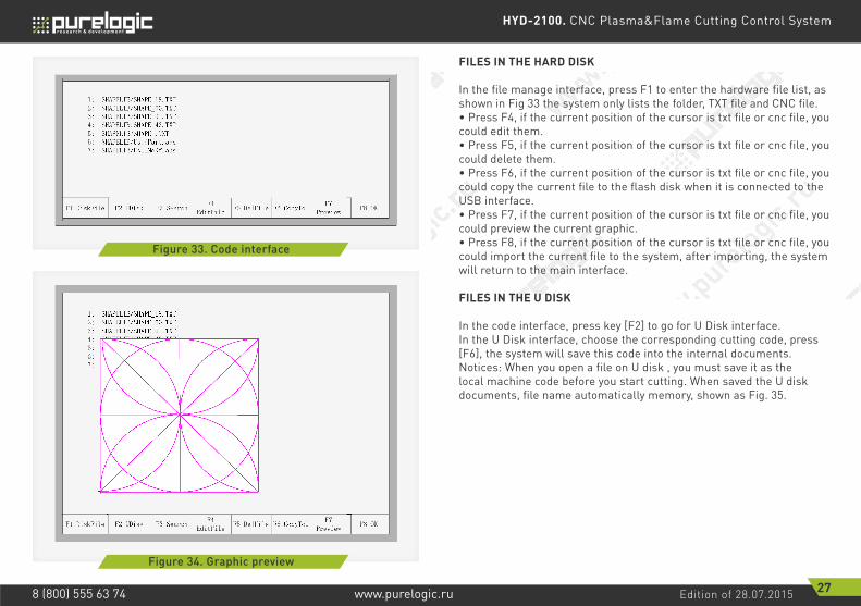
FILES IN THE HARD DISK
In the file manage interface, press F1 to enter the hardware file list, as shown in Fig 33 the system only lists the folder, TXT file and CNC file.• Press F4, if the current position of the cursor is txt file or cnc file, you could edit them.• Press F5, if the current position of the cursor is txt file or cnc file, you could delete them.• Press F6, if the current position of the cursor is txt file or cnc file, you could copy the current file to the flash disk when it is connected to the USB interface.• Press F7, if the current position of the cursor is txt file or cnc file, you could preview the current graphic. • Press F8, if the current position of the cursor is txt file or cnc file, you could import the current file to the system, after importing, the system will return to the main interface.
FILES IN THE U DISK
In the code interface, press key [F2] to go for U Disk interface.In the U Disk interface, choose the corresponding cutting code, press [F6], the system will save this code into the internal documents.Notices: When you open a file on U disk , you must save it as the local machine code before you start cutting. When saved the U disk documents, file name automatically memory, shown as Fig. 35.
F1 DiskFile F2 UDisk F3 SearchF4
EditFileF5 DelFile F6 CopyToU
F7 Preview
F8 OK
1: SHAPELIB/SHAPE_18.TXT2: SHAPELIB/SHAPE_00.TXT3: SHAPELIB/SHAPE_01.TXT4: SHAPELIB/SHAPE_43.TXT5: SHAPELIB/SHAPE_.TXT6: SHAPELIB/UsedPart.abs7: SHAPELIB/UsedNoKf.abs
F1 DiskFile F2 UDisk F3 SearchF4
EditFileF5 DelFile F6 CopyToU
F7 Preview
F8 OK
1: SHAPELIB/SHAPE_18.TXT2: SHAPELIB/SHAPE_00.TXT3: SHAPELIB/SHAPE_01.TXT4: SHAPELIB/SHAPE_43.TXT5: SHAPELIB/SHAPE_.TXT6: SHAPELIB/UsedPart.abs7: SHAPELIB/UsedNoKf.abs
Figure 33. Code interface
Figure 34. Graphic preview

HYD-2100. CNC Plasma&Flame Cutting Control System
Edition of 28.07.2015 28www.purelogic.ru8 (800) 555 63 74
F1 DiskFile F2 UDisk F3 SearchF4
EditFileF5 DelFile
F6 CopyToDisk
F7 Preview
F8 OK
1: SHAPELIB/SHAPE_18.TXT2: SHAPELIB/SHAPE_00.TXT3: SHAPELIB/SHAPE_01.TXT4: SHAPELIB/SHAPE_43.TXT5: SHAPELIB/SHAPE_.TXT6: SHAPELIB/UsedPart.abs7: SHAPELIB/UsedNoKf.abs
File name:
\SHAPE_43.TXT
F1 DiskFile F2 UDisk F3 SearchF4
EditFileF5 DelFile
F6 CopyToDisk
F7 Preview
F8 OK
1: SHAPELIB/SHAPE_18.TXT2: SHAPELIB/SHAPE_00.TXT3: SHAPELIB/SHAPE_01.TXT4: SHAPELIB/SHAPE_43.TXT5: SHAPELIB/SHAPE_.TXT6: SHAPELIB/UsedPart.abs7: SHAPELIB/UsedNoKf.abs
File exist, confirm to cover?ENTER: confirm / ESC: cancel
Figure 35. Save U disk files Figure 36. Replacement documents
When input file name, if you do not want to change the file name, you can be directly press [Enter] to preserved; or modify the file name and then press [Enter] to save. If the same named file has already exited, the system prompts (Fig. 36). If you want to replace the internal documents, press [Enter] key, if you want to change the file name, press [Esc], change the file name and then save.
HYD-2100. CNC Plasma&Flame Cutting Control System
Edition of 28.07.2015 29www.purelogic.ru8 (800) 555 63 74
F1 DiskFile F2 UDisk F4 EditFile
F5 DelFileF6
CopyToDiskF7
PreviewF8 OK
1: SHAPELIB/SHAPE_18.TXT2: SHAPELIB/SHAPE_00.TXT3: SHAPELIB/SHAPE_01.TXT4: SHAPELIB/SHAPE_43.TXT5: SHAPELIB/SHAPE_.TXT6: SHAPELIB/UsedPart.abs7: SHAPELIB/UsedNoKf.abs
Input searched string
_
F3 Search
Figure 37. Search file
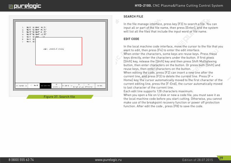
SEARCH FILE
In the file manage interface, press key [F3] to search a file. You can input all or part of the file name, then press [Enter], and the system will list all the files that include the input word or file name.
EDIT CODE
In the local machine code interface, move the cursor to the file that you want to edit, then press [F4] to enter the edit interface.When enter the characters, some keys are reuse keys. Press these keys directly, enter the characters under the button. If first press [Shift] key, release the [Shift] key and then press Shift Multiplexing button, then enter characters on the button. Or press both [Shift] and reuse keys, then enter characters on the button.When editing the code, press [F2] can insert a new line after the current line, and press [F3] to delete the current line. Press [F + Home] key, the cursor automatically moved to the first character of the current editing line, press the [F-End], the cursor automatically moved to last character of the current line.Each edit line supports 128 characters maximum.When you open a file on U disk or new a code file, you must save it as the local machine code before you start cutting. Otherwise, you cannot make use of the breakpoint recovery function or power off protection function. After edit the code , press [F8] to save the code.

HYD-2100. CNC Plasma&Flame Cutting Control System
Edition of 28.07.2015 30www.purelogic.ru8 (800) 555 63 74
F1 compile F2 AddRow F3 Del Row F4 NewFile F8 save
1: G212: G913: _
Figure 38. New code
NEW CODE
In the editing code interface, you can press key [F4] to create an new file to input your own code, shown as Fig. 38.
COMPILE CODE
After create a new code or edit the code, if you want to know the code is valid or not, in the edit interface, press [F1] ,you can compile code to check whether the code is correct.
07 Parameter setting
In the main interface, you can get the parameter interface by pressing key [F3] (Para). The parameter function interface is showed in Fig. 39.

HYD-2100. CNC Plasma&Flame Cutting Control System
Edition of 28.07.2015 31www.purelogic.ru8 (800) 555 63 74
F1 Common F2 Flame F3 Plasma F4 Powder F5 System F6 Import F7 Export F8 Save
mpmm000.005deeps gnittuCmpmm000.0003deeps evom launaMmpmm000.0001deeps evom 00Gmpmm000.0002deeps kcab/omeDmpmm000.0001deeps tsuD
mm000.0eulav freKmpmm %00.001)001-1(deeps renroC
>-<emalFepyt gnittuCmpmm00.005deepS nuR omeD
Figure 39. Parameter Interface
You can set five kinds of parameter in the parameter interface:1) Common parameters: cutting speed, manual move speed, G00 move speed, the size of kerf gap, corner speed, cutting type, edge cut enable, hold preheat.2) Flame parameters: all the parameters used in oxygen gas cutting.3) Plasma parameters: all the parameters used in plasma cutting.4) Maring parameters: ignition, perforation cycle parameters, dry dusting offset.5) System parameters: you can set system pulses, maximum speed limit, motor parameters and soft limit parameters.
COMMON PARAMETERS
It is the favorite’s parameters in Fig. 39.• Cutting Speed: the maximum cutting speed, unit is mm/m. • Manual Move Speed: the moving speed of cutting torch in manual, unit is mm/m.• G00 Move Speed: the cutting torch speed when G00 is executed or the cutting torch go back to the reference or some other occasion, unit is mm/m.• Kerf: According to the cutting gap width, users set Kerf Gap compensation(the value should be half of the cutting gap ) to ensure the dimensional precision, the system will generate a new path automatically to make compensation to work piece.
Before cutting a work piece, you can modify kerf gap value, once begin to cut, you are not permitted to modify the value. • Corner speed: Plate thickness affect the cutting tip’s ac/dc rate when it moving. The angle between the end of a cut-point line’s tangential direction and the direction of the tangent line of the beginning of next cutting point, and the thickness of plate determines cutting tip speed at the transition. If the normal cutting speed is V, angle is α, plate thickness is h, then cutting tip speed in at the time of intersection is Vx
Notice: The unit is mm. The max thickness of plate is 100 mm, if more than 100mm also are considered to be 100mm.• Cutting Type: There are two cutting types : Oxygen fuel gas and Plasma parameters. You can press [←] or [→] to switch with them.
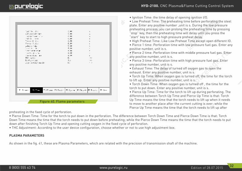
FLAME PARAMETERS
The oxygen fuel parameters, in Fig 40, control time delay in IO operation, and whether use high adjustment.
VhVx πα50
=
HYD-2100. CNC Plasma&Flame Cutting Control System
Edition of 28.07.2015 32www.purelogic.ru8 (800) 555 63 74
F1 Common F2 Flame F3 Plasma F4 Powder F5 System F6 Import F7 Export F8 Save
s00.0emit noitingIs00.0emit taeherp woLs00.0emit taeherp hgiHs00.0emit 1 ecreiPs00.0emit 2 ecreiPs01.0emit 3 ecreiPs00.0emit tsuahxEs00.0emit pu hcroTs00.0emit nwod hcroTs00.0emit pu ecreiPs00.0emit nwod ecreiP>-<oNelbane CHT>-<seYtaeherp dloH>-<oNelbane gnittuc egdE
Figure 40. Flame parameters
• Ignition Time: the time delay of opening ignition I/O.• Low Preheat Time: The preheating time before perforating the steel plate. Enter any positive number ,unit is s. During the low pressure preheating process, you can prolong the preheating time by pressing “stop” key, then the preheating time will delay until you press the “start” key to start to high pressure preheat delay.• High Preheat Time: Like Low Preheat Time except open different IO.• Pierce 1 time: Perforation time with low pressure fuel gas. Enter any positive number, unit is s.• Pierce 2 time: Perforation time with middle pressure fuel gas. Enter any positive number, unit is s.• Pierce 3 time: Perforation time with high pressure fuel gas. Enter any positive number, unit is s.• Exhaust Time: The delay of turned off oxygen gas to open the exhaust. Enter any positive number, unit is s.• Torch Up Time: When oxygen gas is turned off, the time for the torch to lift up. Enter any positive number, unit is s.• Torch Down Time: When oxygen gas is turned off , the time for the torch to put down. Enter any positive number, unit is s.• Pierce Up Time: Time for the torch to lift up during perforating. The difference between Torch Up Time and Pierce Up Time is that: Torch Up Time means the time that the torch needs to lift up when it needs to move to another place after the current cutting is over; while the Pierce Up Time means the time that the torch needs to lift up after
preheating in the fixed cycle of perforation.• Pierce Down Time: Time for the torch to put down in the perforation. The difference between Torch Down Time and Pierce Down Time is that: Torch Down Time means the time that the torch needs to put down before preheating; while the Pierce Down Time means the time that the torch needs to put down after finishing Torch Up Time and opening cutting oxygen in the fixed cycle of perforation.• THC Adjustment: According to the user device configuration, choose whether or not to use high adjustment box.
PLASMA PARAMETERS
As shown in the fig. 41, these are Plasma Parameters, which are related with the precision of transmission shaft of the machine.

HYD-2100. CNC Plasma&Flame Cutting Control System
Edition of 28.07.2015 33www.purelogic.ru8 (800) 555 63 74
F1 Common F2 Flame F3 Plasma F4 Powder F5 System F6 Import F7 Export F8 Save
s00.0emit crAs00.0emit ecreiPs00.0emit pu hcroTs00.0emit kcehc gnicrAs00.0emit kcehc noitisoPs00.0emit pu noitisoP
%mpmm00.0cra esolCmm00.0crA esolc ot ecnatsiD
s00.0yaled cra esoL>-<oNelbane cra hctaW
Figure 41. Plasma parameters
• Arc time: Before the arc starting, the system time to wait. At this point, all output I /O are turned off. Enter any positive number, unit is s.• Pierce time: Perforation time. Enter any positive number, unit is s.• Torch Up Time: When arc press is turned off, the time for the torch to lift up. Enter any positive number, unit is s.• Arcing Check Time: Enter any positive number, unit is s. If not detected any feedback signal of success arc starting within the detection time, the system prompts an error message and terminates the current work of cutting, according memory breakpoints to withdraw from the program.• Position check Time: Enter any positive number, unit is s. Delay time of the success of position check.• Position up Time: Enter any positive number, unit is s. Before positioning check, the time for the torch to lift up.• Close arc: In setting the rate of X%, open the output port, close the arc press signal, to prevent the steel melting under low-speed cutting tip due to temperature is too high.• Distance to close arc: in the minimum distance of the cutting line of the initial segment or end segment, close the arc voltage increases.• Lose arc delay: detect the delay time of the feedback of the broken arc, if there’s still no arc voltage input, the situation is considered to be broken arc. This parameter can effectively avoid the arc broken alert because of the sensitivity of the broken arc detection in the cutting methods with lead, this guarantees the continuousness of the
cutting and avoid the interrupt of frequent alert .• Watch arc enable: Real-time detection of arc voltage signal in cutting process.
If setting «yes», in the cutting process, the system detects he real-time arc voltage feedback signal. If do not detect the signal, the system terminates the current work of cutting, according memory breakpoints to withdraw from the program. If installing a «No», then in the cutting process does not detect arc voltage feedback signal.
POWDER PARAMETERS
As shown in the Fig. 42, these are Powder Parameters, which are related with the precision of transmission shaft of the machine.

HYD-2100. CNC Plasma&Flame Cutting Control System
Edition of 28.07.2015 34www.purelogic.ru8 (800) 555 63 74
F1 Common F2 Flame F3 Plasma F4 Powder F5 System F6 Import F7 Export F8 Save
0emit noitingI tsuD .00 ss00.0emit taeherp tsuDs00.0emit nepO tsuD esiaRs00.0emit esolC tsuD esiaRs00.0emit pU tsuDs00.0emit nwoD tsuDmm00.0tesffO latnoziroH tsuDmm00.0tesffO lacitreV tsuD
F1 Common F2 Flame F3 Plasma F4 Powder F5 System F6 Import F7 Export F8 Save
mm/n000.521esluP sixA latnoziroHmm/n000.521esluP sixA lacitreVmpmm000.0002deeps gnittuc xaMmpmm000.0006deeps 00G xaMmpmm000.0003deeps launaM xaMmpmm000.005timil cra llamS
s04.0emit tsujda emalFs03.0emit tsujda amsalPs80.0emit pots ycnegremEmm000.052deeps tratSmm000.000001X+ xaMmm000.000001Y+ xaMmm000.000001-X- niMmm000.000001-Y- niM
Figure 42. Powder parameters Figure 43. System parameters
• Dust Ignition Time: Enter any positive number, unit is s.• Dust Preheat Time: Enter any positive number, unit is s.• Raise Dust Open / Close Time: The time of raise dusting port relatively to the powder port. Enter any positive number, unit is s.• Dust Up Time: The time for the torch to lift up.• Dust Down Time: The time for the torch to put down.• Dust Horizontal Offset: The horizontal displacement of powder gun relative to the cutting tip.• Dust Vertical Offset: The Vertical displacement of powder gun relative to the cutting tip.
SYSTEM PARAMETERS
The system parameters, as showed in Fig 7.5, are related with the precision of transmission shaft of the machine. • Horizontal Axis Pulse: The number of pulse that system needs to generate when the machine move1mm towards X axis, maintaining 3 digits at most after decimal point.• Vertical Axis Pulse: The number of pulse that system needs to generate when the machine move 1mm towards Y axis , maintaining 3 digits at most after decimal point.• Max Cutting Speed: the maximum cutting speed, unit is mm./m.• Max G00 speed: the allowable maximum speed when cutting tips idling.• Small Arc Limit: Maximum speed at cutting a small arc.

HYD-2100. CNC Plasma&Flame Cutting Control System
Edition of 28.07.2015 35www.purelogic.ru8 (800) 555 63 74
Small arc definition:0 mmpm< cutting speed <2000mmpm small arc=5mm2000 mmpm< cutting speed <4000mmpm small arc =10mm4000 mmpm< cutting speed <6000mmpm small arc =15mm6000 mmpm< cutting speed <8000mmpm small arc =20mm8000 mmpm< cutting speed <10000mmpm small arc =25mm10000mmpm< cutting speed <12000mmpm small arc =30mm12000mmpm< cutting speed <15000mmpm small arc =35mm• Flame adjust time: the whole time for the system accelerates from its start speed to the expected cutting speed.• Plasma adjust time: when plasma cutting , from the time the motor starts to the time when the motor is up to the cutting speed.• Emergency STOP Time: When encounter Emergency Stop input, the time for dropped from the current speed to zero.• Start Speed: the system’s speed when it began to start. Generally do not have to start from 0 , motor will allow a start speed.• Max Coordinate: The maximum positive coordinate which the machine can reach horizontally. Its unit is mm(millimeter). If current coordinate exceeds the value, the system will stop running.• Min Coordinate: The minimum negative coordinate which the machine can reach horizontally. Its unit is mm(millimeter). If current coordinate is less than the value, the system will stop running.
PARAMETER IMPORT
In the parameter configuration interface, press F6 to import the parameters. The parameters should satisfy two conditions:1. The parameters exported from the incising machine control system should satisfy the specified format. The file format is F2500.DAT2. The file should be stored under the root folder of flash disk which is connected to the USB interface.When the above condition is satisfied, in the Fig. 44, press Enter to confirm, and then you could import the backup parameters to the system.

HYD-2100. CNC Plasma&Flame Cutting Control System
Edition of 28.07.2015 36www.purelogic.ru8 (800) 555 63 74
Figure 44. Parameter import Figure 45. Parameter export
PARAMETER EXPORT
After the parameter configuration is over, press F7 in the parameter configuration interface to export the parameters, you should connect the flash disk to the USB interface before exporting.In the interface shown in Fig. 45, after pressing Enter, the parameters will automatically be saved in the root folder of flash disk, the file name is F2500.DAT
SAVE PARAMETERS
After parameter modification, press [F8] to save, shown in Figure 46.
HYD-2100. CNC Plasma&Flame Cutting Control System
Edition of 28.07.2015 37www.purelogic.ru8 (800) 555 63 74
F1 Input kcehCfleS 6FdrByeK 5FtuptuO 2FF7
DataTimeF8
SystemDef
input
Forward limit
Back limit
Right limit
Left limit
Emergency stop
Arcing feedback
Position detect
Plasma crash
Up move input
Down move input
Left move input
Right move input
Acceleration input
Deacceleration input
Torch up input
Torch down input
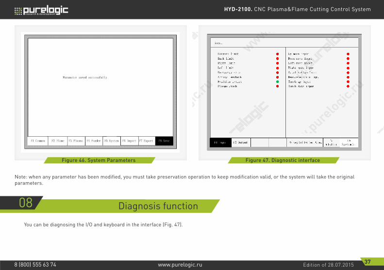
Figure 46. System Parameters Figure 47. Diagnostic interface
Note: when any parameter has been modified, you must take preservation operation to keep modification valid, or the system will take the original parameters.
08 Diagnosis function
You can be diagnosing the I/O and keyboard in the interface (Fig. 47).

HYD-2100. CNC Plasma&Flame Cutting Control System
Edition of 28.07.2015 38www.purelogic.ru8 (800) 555 63 74
DIAGNOSIS INTERFACE INDEX
Input DiagnosisThe system will read current IO information when press [F1] (Refresh) to refresh the interface, and display all IO’s status. “On” means the input is effective, and “Off” means the input is ineffective.
Output DiagnosisIn diagnosis interface ,press [F2] to enter output diagnosis interface, shown as Fig. 48. Press [↑], [↓], [←], [→], you can move the cursor to the corresponding output port, press [F3] to open the corresponding output port, press [F4] to close the corresponding output. – Represents the valid output. – Represents the invalid output.
F5 System Diagnosis
F1 Input Diagnosis
F2 Output Diagnosis
F6System Self-test
F8System Definition
F1 Parameters
ResetParameters
F2
Backup
F3 Definition
F4 Encryption
F5 Decrption
F6 Language
F5Keyboard Diagnosis
F7Date time
F1 Input F2 Output F5 KeyBrd F6 SelfCheckF7
DataTimeF8
SystemDef
Output
Ignition
Low preheat
High preheat
Low Oxygen
Medium Oxygen
High Oxygen
Torch up
Torch down
exhaust
THC enable
Position detect
Arc starting
HoldTorch
Dust spray
Raise dust
Dust preheat
F3 OpenOutF4 CloseOut
Figure 48. Output diagnosis
HYD-2100. CNC Plasma&Flame Cutting Control System
Edition of 28.07.2015 39www.purelogic.ru8 (800) 555 63 74
F1 Input F2 Output F5 KeyBrdF6
SelfCheckF7
DataTimeF8
SystemDef
1. backup parameter first all2. lose breakpoint3. restart after selfcheck
Are you sure?
Figure 49. Keyboard diagnosis Figure 50. System self-check
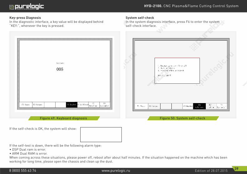
Key-press DiagnosisIn the diagnostic interface, a key value will be displayed behind “KEY:”, whenever the key is pressed.
If the self-check is OK, the system will show:
If the self-test is down, there will be the following alarm type:• DSP Dual ram is error.• ARM Dual RAM is error.When coming across these situations, please power off, reboot after about half minutes. If the situation happened on the machine which has been working for long time, please open the chassis and clean up the dust.
System self-checkIn the system diagnosis interface, press F6 to enter the system self-check interface.

HYD-2100. CNC Plasma&Flame Cutting Control System
Edition of 28.07.2015 40www.purelogic.ru8 (800) 555 63 74
F1 Input F2 Output F5 KeyBrd F6 SelfCheckF8
SystemDef
2010-08-21 15:51:37 Sun
Up or down to modify
F7 DataTime
Figure 51. Keyboard diagnosis
DATE AND TIME
Press F7 in the system diagnosis interface to set the date and time.
Move the cursor to the corresponding date, time or week, press [↑]or [↓] to adjust the time.
SYSTEM DEFINITION
In the system diagnosis interface, press F8 to enter the system custom definition interface, in the interface, you could set the input IO, output IO or system coordinate, also reset or backup the parameters and one key switch between English or Chinese.
Parameter backup and restoreParameter Backup: The process of parameter backup is, in the main interface press F5 (System Diagnosis), F8 (System Definition), F2 (Parameter Backup). The system will need code, after inputting the code “1396”, press Enter, the system will import the default parameters. In the following process, if the parameters is modified or some of them is broken, reset the parameters.Warning: after adjusting the equipment, please backup the parameters.
Parameter Reset: The process of reset the parameters is, press F5 (System Diagnosis) in the main interface, F8 (System Definition), F1 (Parameter Reset).Warning: After resetting successfully, please restart the system.
Input definitionThe controller could change the IO definition, including changing the order of IO number, the type of IO( normally open or closed) according to the user’s need. In the system custom definition interface, press F3 to enter the definition interface, press F1 to enter the input definition interface.As shown in fig. 52.
In the interface press [↑], [↓], [←], [→], move the cursor to the position that needs changing, press [PageUp] or [PageDown] to change the number of the Input, press [Enter] to change the type of the input.If the external type of input is normally closed, please set the IO type to , if the type is normally open, please set the IO type to .

HYD-2100. CNC Plasma&Flame Cutting Control System
Edition of 28.07.2015 41www.purelogic.ru8 (800) 555 63 74
F1 Input F2 Output F8 Save
Definition of input
Forward limit 02
Back limit 15
Left limit 14
Right limit 01
Sharpstop 03
ArcFeedback 04
PosFeedback 05
PlasmaCrash 06
Up move input 09
Down move input 10
Left move input 07
Right move input 08
Acceleration input 16
Deacceleration input 17
Torch up input 18
Torch down input 19
F3 Axes F4 Motor
Port Type Port Type
Port- Press PgUp/PDn Type-Press Enter
F1 Input F2 Output F8 Save
Definition of output
Ignition 03
LowPreheat 01
HighPreheat 17
LowOxygen 04
MidOxygen 05
HighOxygen 14
TorchUp 02
TorchDown 15
Exhaust 06
THC 08
PosDetect 19
ArcStart 16
LowSpdInCorner 18
Dust spray 07
Raise dust 20
Dust preheat 21
F3 Axes F4 Motor
Port Type Port Type
Port- Press PgUp/PDn Type-Press Enter
Figure 52. Input definition Figure 53. Output definition
Output definitionThe controller could change the IO definition, including changing the order of IO number, the type of IO (normally open or closed) according to the user’s need. In the system custom definition interface, press F3 to enter the definition interface, press F1 to enter the input definition interface. As shown in fig. 53.
In the interface press [↑], [↓], [←], [→], move the cursor to the position that needs changing, press [PageUp], [PageDown] to change the number of the Output, press [Enter] to change the type of the Output.The output type is open drain transistor output type. Type means that if the output signal is effective, the transistor is on. Type means that isthe output signal is effective, the transistor is off.
Coordinate definitionThe system could provide IO definition for the user. As shown in Fig. 54.

HYD-2100. CNC Plasma&Flame Cutting Control System
Edition of 28.07.2015 42www.purelogic.ru8 (800) 555 63 74
F8 saveF2 output F3 Axes
+Y↑
-X ← → +X↓-Y
Press Enter to change coordinate
rotoM 4Ftuptuo 1F
Figure 54. Coordinate Definition
In the interface, press Enter repeatedly to change among 8 type of coordinates. Press F8 to save.
09 Graph
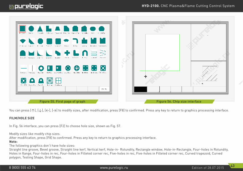
In the main interface, press [F1] (ShapeLib) to enter graph interface, shown as follows (Fig. 55).
You can press [↑], [↓], [←], [→] to choose different graph.
CHOOSE GRAPH
In home interface of graph, move the cursor to the required graph, press [F8] to confirm, shown as Fig. 56.
HYD-2100. CNC Plasma&Flame Cutting Control System
Edition of 28.07.2015 43www.purelogic.ru8 (800) 555 63 74
F8 OK
Rectangle lavOelgnairTelcriC L-Bracket Trapezoid Slant Rec
CirSector
GambrelRec RoofedRec CircleFla
ConcaveT FLange Elbow
ConcaveP.
Convex RecinRec
ConcaveR. ConcaveT BevelRec Cross L Corner U Shape Groove1 Groove2
Horizont Vertical HoleCir. RecWin. Hole-in-Rec. HolesCir. HolesFla. 4HoleRec. 4HolesRec. 5HolesRec.
CurvedTr. CurveP. Testing GridShape
ceRnielcriC.RevacnoC.RrenroCnogatcO
ConvexR.
5HolesRec.
Figure 55. First page of graph Figure 56. Chip size interface
You can press [↑], [↓], [←], [→] to modify sizes, after modification, press [F8] to confirmed. Press any key to return to graphics processing interface.
FILM/HOLE SIZE
In Fig. 56 interface, you can press [F2] to choose hole size, shown as Fig. 57.
Modify sizes like modify chip sizes.After modification, press [F8] to confirmed. Press any key to return to graphics processing interface.Note:The following graphics don’t have hole sizes:Straight line groove, Bevel groove, Straight line kerf, Vertical kerf, Hole-in- Rotundity, Rectangle window, Hole-in-Rectangle, Four-holes in Rotundity, Holes in flange, Four-holes in rec, Four-holes in Filleted corner rec, Five-holes in rec, Five-holes in Filleted corner rec, Curved trapezoid, Curved polygon, Testing Shape, Grid Shape.

HYD-2100. CNC Plasma&Flame Cutting Control System
Edition of 28.07.2015 44www.purelogic.ru8 (800) 555 63 74
+24V+3.3V
24VG3.3VG
System
External input signal
To CPU
Figure 57. Hole size
Figure 58. Input port circuit
10 Port explanation
INPUT PORT (FIGURE 58)
• Input signal is a mechanical contact switch, normally open type, it is effective when it is connected to 24VG,and it is ineffective when it is float or connected to 24V• 16 input ports totally• Input signal definition

HYD-2100. CNC Plasma&Flame Cutting Control System
Edition of 28.07.2015 45www.purelogic.ru8 (800) 555 63 74
Signal name
X- limit
Arcing successfully
Y- limit
Move right/D
Plasma collision
X+ limit
Y+ limit
Positioning successfully
Emergency stop
Move left/C
X+ stop input, float it if not use, this is horizontal1
Pin number
Y+ stop input, float it if not use, this is vertical
Emergency stop input, float if not use
Remote control input
2
5
3
7
14
4
15
8
6
Remark
X- stop input, float it if not use, this is horizontal
Y- stop input, float it if not use, this is vertical
Remote control input

HYD-2100. CNC Plasma&Flame Cutting Control System
Edition of 28.07.2015 46www.purelogic.ru8 (800) 555 63 74
1Right limit
14
2
15
3
16
4
17
5
18
6
19
7
20
8
21
9
22
10
23
11
24
12
25
13
Left limit
Front limit
Back limit
Emergency Stop
Arcing successfully
Positioning successfully
Plasma collision
ignition
Cutting oxygen
Torch up
Torch down
Move left
NC
Move right
NC
Move ahead
NC
Move backward
NC
NC
+24V
+24V
24VG
24VG
com
Right limit input
Left limit input
Front limit input
Back limit input
Emergency stop input
Arcing successfully
feedback
Positioning successfully feedback
Plasma collision feedback
1.For Plasma cutting2.Accessed when CNC positioning is needed. And positioning successfully input should be configured as normally open type. Or it can be not accessed when using height adjusting device to positioning.3.When plasma collision detection is needed, accessed to plasma collision feedback.
Caution: All inputs can be normally closed or normally open, and all inputs are normally open in defualt.
(connecting to 24VG of the system or connecting to the 24VG
of the external 24V switching power supply.)
Remote Input The system supports two external remote control input, one for line input type, the other for 8421 encoded input type.
• Line Input TypeThe pin 7, 8, 9, 10 of input port represents left, right, forward, backward, when inputting valid signal , the machine can move toward the corresponding direction, when the input signal is invalid, the machine stop moving.When the input signal of pin 16 is valid, the system will ignite the torch, the ignition time is the setting value in system parameters, please take the reference of part of «ignition time» in «7.2 oxygen gas parameters».When the input signal of pin 17 is valid, the system will turn on or off thecutting oxygen. When the cutting oxygen is on, the system cut off the oxygen, when the cutting oxygen is off, open the cutting oxygen system.When the input signal of pin 18 is valid, the system will raise the cutting torch, when the signal invalid, the torch stops.When the input signal of pin 19 is valid, the torch goes down, when the signal invalid, the cutting torch stops.The external switches of line input are designed by the user.
• 8421 code inputInput pin 9, 10, 7, 8 is the A, B, C, D bits of the 8421 code.

HYD-2100. CNC Plasma&Flame Cutting Control System
Edition of 28.07.2015 47www.purelogic.ru8 (800) 555 63 74
8421 code (DCBA)
0001
0101
1101
0011
1011
1001
0111
1111
0000
0010
1010
0110
1110
0100
1100
1000
No Input0
Decimal
Go back according to the original track
Move forward vertically
Ignite Input
Raise the cutting torch
Left lateral movement
Cutting torch
Slow down
Start
Accelerate
2
10
6
14
4
12
8
1
5
13
3
11
9
7
15
Function
Turn on or off the cutting oxygen
Move forward according to the original track
Pause
Start
Move toward right horizontally
Move for the negative direction vertically
8421-type remote control input is designed by the user, the user can also use the company’s wireless remote control module.
INPUT CONFIGURATION
The number and type of input port can be reconfigured. For example, the right input port can be Pin 1, also can be configured to Pin 7, input type can be normally open type, can also be normally close type. Configuration methods are shown in Fig. 59.Press F5 (Diagnosis), F8 (SystemDef), F3 (Define), enter the password «1396» and press ENTER in turn on the main Interface.

HYD-2100. CNC Plasma&Flame Cutting Control System
Edition of 28.07.2015 48www.purelogic.ru8 (800) 555 63 74
F1 Input F2 Output F8 Save
Definition of input
Forward limit 02
Back limit 15
Left limit 14
Right limit 01
Sharpstop 03
ArcFeedback 04
PosFeedback 05
PlasmaCrash 06
Up move input 09
Down move input 10
Left move input 07
Right move input 08
Acceleration input 16
Deacceleration input 17
Torch up input 18
Torch down input 19
F3 Axes F4 Motor
Port Type Port Type
Port- Press PgUp/PDn Type-Press Enter
+24V+3.3V
24VG3.3VG
System
External input signal
To CPU
Figure 59. Input Port Configuration
Figure 60. Output port circuit
In the input configuration interface, move the cursor to numbers of the serial number, Press the PgUp or PgDn to change the input port number, which also change the pin number of 25-pin input terminal. Move the cursor to place, you can press ENTER to change the input type. “ ” is for the normally open type of the input, when invalid, it is for the signal of turning off, when effective, it is for the signal of closure. “ ”is the normally closed type of input, when invalid, it is the signal of closure, when effective, it is the signal of turning off.
OUTPUT PORT (FIGURE 60)
• Output voltage is 24VDC, low level is effective.• Maximum output current Imax = 300mA.• 16 output ports totallu.• Output signal definition.

HYD-2100. CNC Plasma&Flame Cutting Control System
Edition of 28.07.2015 49www.purelogic.ru8 (800) 555 63 74
Signal
Low pressure preheat
High pressure cutting oxygen
Spray dust
+24V
Low pressure cutting oxygen
Plasma arc starting
Enable high adjusting box
Torch down
Dusting Preheat
Ignite
High pressure preheat
Plasma locating
Torch up
Raise dust
24VG
Medium pressure cutting oxygen
Corner low-speed output. Or automatic / manual
Not used
Exhaust
3
25 Chip interface Pin No.(Mainconnector)
+24V/3A output
17
19
2
20
13, 25
5
18
9, 10, 22, 23
6
1
14
07
11, 12, 24
4
16
8
15
21
Remark
+24V ground
HYD-2100. CNC Plasma&Flame Cutting Control System
Edition of 28.07.2015 50www.purelogic.ru8 (800) 555 63 74
1Low pressure
preheat
14
2
15
3
16
4
17
5
18
6
19
7
20
8
21
9
22
10
23
11
24
12
25
13
High pressure cutting oxygen
Torch up
Torch down
Ignite
Low pressure cutting oxygen
Mid-pressure preheat
exhaust
Plasma arc starting
High pressure preheat
Low rate at corner
Plasma positioning
Spray powder
Raise powder
Enable height adjusting
Powder preheating
unused
unused
unused
unused
+24V
+24V
+24V
24VG
24VG
COM
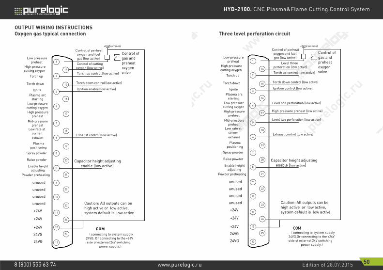
Caution: All outputs can be high active or low active, system default is low active.
(connecting to system supply 24VG. Or connecting to the +24V side of external 24V switching
power supply.)
Control of gas and preheat oxygen valve
+24V(common)
Control of cutting oxygen (low active)
Torch up control (low active)
Torch down control (low active)
Ignition enable (low active)
Capacitor height adjusting enable (low active)
Control of perheat oxygen and fuel gas (low active)
Exhaust control (low active)
1Low pressure
preheat
14
2
15
3
16
4
17
5
18
6
19
7
20
8
21
9
22
10
23
11
24
12
25
13
High pressure cutting oxygen
Torch up
Torch down
Ignite
Low pressure cutting oxygen
Mid-pressure preheat
exhaust
Plasma arc starting
High pressure preheat
Low rate at corner
Plasma positioning
Spray powder
Raise powder
Enable height adjusting
Powder preheating
unused
unused
unused
unused
+24V
+24V
+24V
24VG
24VG
COM
Caution: All outputs can be high active or low active, system default is low active.
(connecting to system supply 24VG.Or connecting to the +24V side of external 24V switching
power supply.)
Control of gas and preheat oxygen valve
+24V(common)
Level three perforation (low active)
Torch up control (low active)
Torch down control (low active)
Ignition control (low active)
Capacitor height adjusting enable (low active)
Control of perheat oxygen and fuel gas (low active)
Exhaust control (low active)
Level one perforation (low active)
High pressure preheat (low active)
Level two perforation (low active)
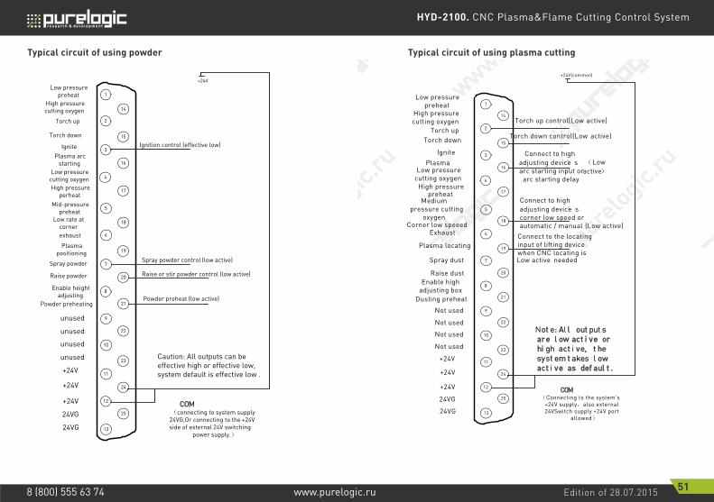
OUTPUT WIRING INSTRUCTIONSOxygen gas typical connection Three level perforation circuit
HYD-2100. CNC Plasma&Flame Cutting Control System
Edition of 28.07.2015 51www.purelogic.ru8 (800) 555 63 74
1Low pressure
preheat
14
2
15
3
16
4
17
5
18
6
19
7
20
8
21
9
22
10
23
11
24
12
25
13
High pressure cutting oxygen
Torch up
Torch down
Ignite
Low pressure cutting oxygen
Mid-pressure preheat
exhaust
Plasma arc starting
High pressure perheat
Low rate at corner
Plasma positioning
Spray powder
Raise powder
Enable height adjusting
Powder preheating
unused
unused
unused
unused
+24V
+24V
+24V
24VG
24VG
COM
Caution: All outputs can be effective high or effective low, system default is effective low .
(connecting to system supply 24VG,Or connecting to the +24V side of external 24V switching
power supply.)
+24V
Ignition control (effective low)
Spray powder control (low active)
Raise or stir powder control (low active)
Powder preheat (low active)
1Low pressure
preheat14
2
15
3
16
4
17
5
18
6
19
7
20
8
21
9
22
10
23
11
24
12
25
13
High pressure cutting oxygen
Torch upTorch down
Ignite
Low pressure cutting oxygen
Medium pressure cutting
oxygen
Exhaust
Plasma
High pressure preheat
Corner low speeed
Plasma locating
Spray dust
Raise dustEnable high
adjusting boxDusting preheat
Not used
Not used
Not used
Not used
+24V
+24V
+24V
24VG
24VG
COM
Not e: Al l out put s are l ow act i ve or hi gh act i ve, t he syst em t akes l ow act i ve as def aul t .
(Connecting to the system’s +24V supply,also external 24VSwitch supply +24V port
allowed)
+24V(common)
Torch up control(Low active)
Torch down control(Low active)
Connect to high adjusting device’ s arc starting input or
arc starting delay
Connect to high adjusting device’ s corner low speed or automatic / manual
Connect to the locating input of lifting device when CNC locating is
needed
(Low active)
(Low active)
Low active
Typical circuit of using powder Typical circuit of using plasma cutting

HYD-2100. CNC Plasma&Flame Cutting Control System
Edition of 28.07.2015 52www.purelogic.ru8 (800) 555 63 74
INSTRUCTION
• THC wiring with corner low-speed( Corner signal/Torch height control signal)When the THC takes corner low-speed input control signal, the HYD-2100 «corner low speed» output signal is used to control the THC’s corner low-speed input (Auto mode enable/disable signal). The CNC signal is an open-colletor transistor output, with the default low-level effective. When the THC is not matched type, it needs to be converted by the relay.
THC wiring with automatic / manualWhen THC is automatic / manual control function instead of corner low-speed input, the system needs to use the «corner low-speed» output to control the THC’s automatic / manual signal. When the THC is not matched type, it needs to be converted by the Relay. Meanwhile, it needs to change the type of corner low speed from normally-open to normally-closed in the output configuration interface, i.e from red « » to green « ».
• Using THC for initial sense (IHS) When using the locating function of the THC, the locating of CNC should be closed. The approach is to change the input type of successful locating from normally-open to normally-closed in the input configuration interface(Section 10.1.3), i.e from « » to « ». There are two types of locating:The first: locating controlled by the plasma arc starting. CNC output the plasma arc starting, the THC starts arc after IHS, and sends ARC OK signal back to CNC after pierce. Such THC is available on the market like HYD’s XPTHC series. Such devices can connect the «plasma arc starting» output of CNC system to the « arc on with IHS» input of the THC, and at the same time in the plasma parameters set the arc detecting time to the value that allows for completing the testing and starting arc.
Using CNC system locatingWhen using the Initial Sense function of CNC system, first entering the input configuration interface, set the input type of successful location from normally closed to normally open type, ie, from « » to « ». At the same time, return the signal of successful location to the input of the successful location of the CNC.
Output configurationThe number and type of the output could be configured, for example, the igniting output number could be 3, also it could be configured to 07, the output type could be normally open or normally closed. The detailed methods are shown in figure 61.Press F5 (Diagnosis) in the main interface, F8 (Systemdef), F3 (Define), enter the password «1396» and press ENTER, F2 (output).

HYD-2100. CNC Plasma&Flame Cutting Control System
Edition of 28.07.2015 53www.purelogic.ru8 (800) 555 63 74
F1 Input F2 Output F8 Save
Definition of output
Ignition 03
LowPreheat 01
HighPreheat 17
LowOxygen 04
MidOxygen 05
HighOxygen 14
TorchUp 02
TorchDown 15
Exhaust 06
THC 08
PosDetect 19
ArcStart 16
LowSpdInCorner 18
Dust spray 07
Raise dust 20
Dust preheat 21
F3 Axes F4 Motor
Port Type Port Type
Port- Press PgUp/PDn Type-Press Enter
Signal Shaping Photoele
-ctric isolation
Different-ial
output
X Y+Y-
XDIR/XPWM-
XPWM+
YDIR/YPWM-
YPWM+
XDIR+XDIR-
YDIR+YDIR-
XCP+XCP-
YCP+YCP-
System
Figure 61. Output Configuration
Figure 62. Motor port schematic diagram
In the output configuration interface, move the cursor to numbers of the serial number, Press the PgUp or PgDn to change the input port number, that also changes the pin number of 25-pin input terminal. Move the cursor to place, you can press ENTER to change the input type. « » is for the normally open type of the input, when invalid, it is for the signal of turning off, when effective, it is for the signal of closure. « » is the normally closed type of input, when invalid, it is the signal of closure, when effective, it is the signal of turning off.
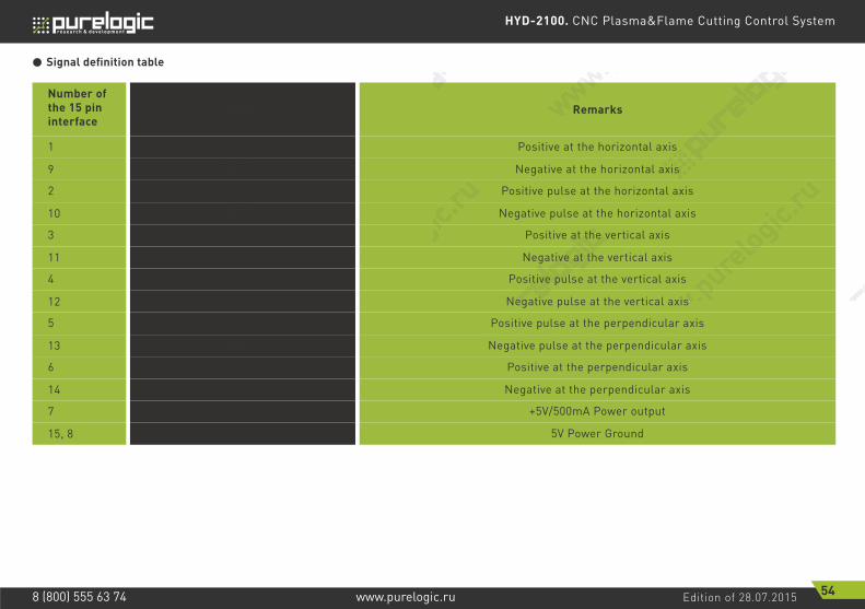
HYD-2100. CNC Plasma&Flame Cutting Control System
Edition of 28.07.2015 54www.purelogic.ru8 (800) 555 63 74
Signal definition table
Signal
XDIR- Negative at the horizontal axis
YDIR- Negative at the vertical axis
5VG 5V Power Ground
XCP- Negative pulse at the horizontal axis
ZDIR- Negative at the perpendicular axis
ZCP- Negative pulse at the perpendicular axis
YCP- Negative pulse at the vertical axis
XDIR+ Positive at the horizontal axis
XCP+ Positive pulse at the horizontal axis
ZDIR+ Positive at the perpendicular axis
YCP+ Positive pulse at the vertical axis
YDIR+ Positive at the vertical axis
+5V +5V/500mA Power output
ZCP+ Positive pulse at the perpendicular axis
1
Number of the 15 pin interface
2
6
4
3
7
5
9
11
15, 8
10
14
13
12
Remarks
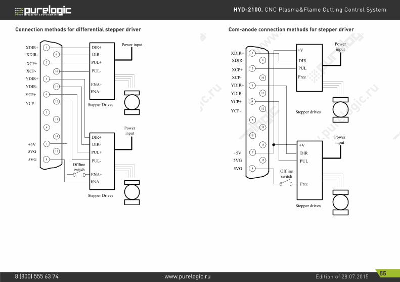
HYD-2100. CNC Plasma&Flame Cutting Control System
Edition of 28.07.2015 55www.purelogic.ru8 (800) 555 63 74
1XDIR+9
2
10
3
11
4
12
5
13
6
14
7
15
8
XDIR-
XCP+
XCP-
YDIR+
YCP+
YDIR-
YCP-
+5V5VG
5VG
DIR+Power input
DIR-
PUL+
PUL-
DIR+
Power input
DIR-
PUL+
PUL-
ENA+
ENA-
Stepper Drives
Stepper Drives
Offline switch
ENA+ENA-
1XDIR+9
2
10
3
11
4
12
5
13
6
14
7
15
8
XDIR-
XCP+
XCP-
YDIR+
YCP+
YDIR-
YCP-
+5V5VG
5VG
DIR
Power input
PUL
DIR
Power input
PUL
Free
Stepper drives
Stepper drives
Offline switch
Free
+V
+V
Connection methods for differential stepper driver Com-anode connection methods for stepper driver

HYD-2100. CNC Plasma&Flame Cutting Control System
Edition of 28.07.2015 56www.purelogic.ru8 (800) 555 63 74
1XDIR+9
2
10
3
11
4
12
5
13
6
14
7
15
8
XDIR-
XCP+
XCP-
YDIR+
YCP+
YDIR-
YCP-
+5V5VG
5VG
5 SING1
Power input
6 SIGN2
3 PULS1
4 PULS2
Power input
Panasonic A5/A4
Panasonic A5/A4
5 SING16 SIGN2
3 PULS1
4 PULS2
Connection methods of Servo driver of Panasonic Company
Figure 63. Coordinate Mapping
Coordinate MappingIn order to change the map coordinates of the system, you need to go tothe define interface. The process is to Press F5 (Diagnosis) in the main interface, F8 (Systemdef), F3 (Define), enter the password «1396» and press ENTER, then press F3 (Axes). As shown in Figure 63.
Continuously press [Enter] key, the direction of the arrow outside coordinates definition will change , the maximum coordinate mapping is eight. After adjusting the direction of the coordinates mapping, press F8 to Save.

HYD-2100. CNC Plasma&Flame Cutting Control System
Edition of 28.07.2015 57www.purelogic.ru8 (800) 555 63 74
11 Installation and debugging
HORIZONTAL / VERTICAL PULSES NUMBER SETTING
Horizontal / vertical pulses number setting It’s easy to set the horizontal (vertical) pulses number. Before drawing a line , assume one value of horizontal pulses XPls and one value of vertical pulses YPls, set these two parameters and then save the settings. Enter the manual interface, choose fixed moving function. Assume the fixed distance is Amm. Move A mm horizontally, and the actual length of the line is B mm (which is generally not equal to A), then we can calculate the horizontal pulses number. The equation is . After calculating , replace the outcome with the assumptive Xpls(take three decimal places at most). Similarly, move C mm vertically, the actual length is D mm, then the vertical pulses number is . Requirement of pulses number:The maximum frequency of output pulses from the system is 200 KHz. It is not possible to work properly according to the order if the pulse frequency is higher than 200KHz. Assume the pulse number is x, the highest speed is Mv (mm/min), then (Mv*x/60) should be less than 200000.For example, the pulse number is x=2000, the highest speed is Mv=12000(mm/min).Because of Mv*x/60=12000*2000/60=400000>200000, the speed of12000(mm/min) is not reachable. If we set x to be 1000, then Mv*x/60 = 12000*1000/60 = 200000, this time it can just to reach the operating speed of 12,000. While in principle the number of pulses can be set to a large value, in fact it should follow these two settings. Because the frequency is too high, some drives can’t work very well, the motor will be out of synchronism. On the other hand, the performance of anti-jamming is of foreign interference is poor, and the external interference is strong.
AXPlsB
•
CYPlsD
•

HYD-2100. CNC Plasma&Flame Cutting Control System
Edition of 28.07.2015 58www.purelogic.ru8 (800) 555 63 74
12 The use of BIOS
Figure 64. Power on Figure 65. BIOS interface
When the system powers on, it will display as shown in Fig. 64. When press DEL before the system counts down to 0, the system will enter the BIOS. If other keys are pressed, the system will enter in before counting down to 0.
System upgradeAfter entering BIOS, press F1 to upgrade the system, it should satisfy the following conditions:Flash Disk is connected to the system. There should be the UserApp.exe upgrade file in the root folder of the flash disk. Pressed F1 to upgrade when the conditions are satisfied, when completing the upgrading, press F6 to reboot.
Welcome interface upgradingAfter entering BIOS, press F2 to upgrade the welcome interface completely, it should satisfy the following conditions:• Flash Disk is connected to the system.• There should be the STARTBMP.BIN upgrade file in the root folder of the flash disk.Pressed F6 to upgrade when the conditions are satisfied, when completing the upgrading, press F6 to reboot.
F1 - System software updateF2 - Welcome picture updateF3 - Motion updateF4 - System backupF5 - System recoveryF6 - Start system
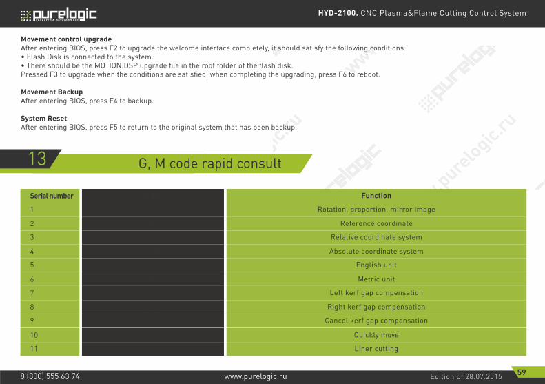
HYD-2100. CNC Plasma&Flame Cutting Control System
Edition of 28.07.2015 59www.purelogic.ru8 (800) 555 63 74
Movement control upgradeAfter entering BIOS, press F2 to upgrade the welcome interface completely, it should satisfy the following conditions:• Flash Disk is connected to the system.• There should be the MOTION.DSP upgrade file in the root folder of the flash disk.Pressed F3 to upgrade when the conditions are satisfied, when completing the upgrading, press F6 to reboot.
Movement BackupAfter entering BIOS, press F4 to backup.
System ResetAfter entering BIOS, press F5 to return to the original system that has been backup.
13 G, M code rapid consult
Order Function
G90
G42
Absolute coordinate system
Right kerf gap compensation
G92
G21
G00
Reference coordinate
Metric unit
Quickly move
G99 Rotation, proportion, mirror image
G20
G40
English unit
Cancel kerf gap compensation
G91
G41
G01
Relative coordinate system
Left kerf gap compensation
Liner cutting
1
5
9
3
7
11
Serial number
4
8
2
6
10

HYD-2100. CNC Plasma&Flame Cutting Control System
Edition of 28.07.2015 60www.purelogic.ru8 (800) 555 63 74
Order Function
M07 Start cutting cycle
G03
M02
Anticlockwise arc cutting
Program end
G02 Clockwise arc cutting
M08 Stop cutting cycle
G04 Program delay
12
16
14
Serial number
15
13
17