Embed Size (px)
Citation preview
ISA Transactions 51 (2012) 373–385
Contents lists available at SciVerse ScienceDirect
ISA Transactions
journal homepage: www.elsevier.com/locate/isatrans
Hybrid sliding mode position control for a piston air motor ball screw tableChia-Hua Lu a, Yean-Ren Hwang b,∗
a Department of Mechanical Engineering, National Central University, Chung-Li, 320, Taiwanb Department of Mechanical Engineering and the Institute of Opto-Mechatronics Engineering, National Central University, Chung-Li, 320, Taiwan
a r t i c l e i n f o
Article history:Received 2 May 2011Received in revised form29 November 2011Accepted 29 November 2011Available online 14 January 2012
Keywords:Fuzzy controlBackstepping sliding mode controlPiston air motorsBall screw tablePosition control
a b s t r a c t
Air motors have been generally applied in the automation industry. Since air motors operate withoutelectricity, they will not produce sparks, explosions or short circuit phenomenon. The purpose of thispaper is to analyze the behavior of a ball screw table actuated by a piston air motor and design a hybrid(backstepping and fuzzy) sliding mode controller for accomplishing accurate position performance. Theexperimental results validate the proposed position control strategy.
© 2011 ISA. Published by Elsevier Ltd. All rights reserved.
1. Introduction
There are many major mechanisms applied to power motioncontrol, such like electromechanical, hydraulic and pneumatic.Electromechanical systems utilize electric motors to drive motion.Hydraulic systems use fluids to yield energy, and pneumaticsystems use a compressible fluid, usually air. Hydraulic systemsbehave less linearly, but are often very efficient for high loadapplications, such as in construction equipment. Pneumaticsystems, air motors, have the advantage of no overheat problemand being clean, using air which is not oiled.
Electric actuators are widely applied in robotics and controlsystems. Compared to conventional electric actuators, pneumaticactuators have a highly nonlinear performance due to thecompressibility of the air. The major advantages of pneumaticactuators are their high payload-to-weight and payload-to-volumeratios, and high speed and force capabilities [1]. The majorlimitation of using air motors for traditional pneumatic actuatorsis their lower efficiency than electric motors, which results fromair leakage from the chamber. Therefore, they need to be designedto be able to withstand the toughest heat, vibration and impactconditions. For example, in the mining industry, in chemicalmanufacturing plants, the airmotorwill not only bemore efficient,but sometimes may be the only device that can be used.
∗ Corresponding author. Tel.: +886 3 4227151x34342; fax: +886 3 4254501.E-mail addresses: [email protected] (C.-H. Lu), [email protected]
(Y.-R. Hwang).
0019-0578/$ – see front matter© 2011 ISA. Published by Elsevier Ltd. All rights reservdoi:10.1016/j.isatra.2011.11.006
In general, due to the limited bandwidth, poor dampingand low stiffness from compressibility lead to limited accuracyand repeatability under variations in payload and pressuresupplied. The compressibility of air results in the highly nonlinearcharacteristics of the pressure dynamics. As a result, conventionalPID feedback controllers are not very effective even for positioncontrol. Even if the control input pressure is a constant, there is stilllittle difference in the positional outputs from each experiment.Consequently, it is difficult to design a position controller capableof realizing accurate position control for radial pistons and van-type air motors at all times. There have been a number ofinvestigations and analyses of the dynamics of van-type air motorscarried out to date. For instance, in the PI (proportional integral)controller [2], air motor system is considered as a first orderlinear system. Although PI control algorithm is simple and highly-reliable when the PI values are adjusted very well, the goodperformance of the PI controller cannot be retained at all timesbecause of variations in the nonlinear characteristics of the airmotor under different operating conditions. A PI controller forhigh speed control was proposed [3] to allow the tracking ofdesired commands at speeds over 3000 rpm given different PIvariables. The Model Reference Adaptive Control (MRAC) [4] isadopted to eliminate the dead-zone caused by friction in fuzzycontrol. The experimental results described in that paper showedthat the mode reference output could be tracked and that
accurate speed control performancewas attainable. A fourth-ordernonlinear mode was developed [5] utilizing parameters identifiedthrough experimental data. However, due to the complexity of thismode, the number of parameters was large, making the process
ed.

374 C.-H. Lu, Y.-R. Hwang / ISA Transactions 51 (2012) 373–385
of deriving parameters complicated and time consuming. Othershave applied control schemes designed to guarantee accurateposition control of pneumatic cylinders [6–8] which are subject tothe uncertain dynamics of pneumatic motion. A method of fuzzysliding mode position control incorporating a ball screw driven byan airmotor has been proposed [9] inwhich fuzzy logic controlwasapplied to avoid the disadvantages of disturbances and chattering.But there are not any descriptions for experimental results ofposition tracking precision.
Backstepping sliding mode control involves dividing a nonlin-ear system into many subsystems. The controller is designed toachieve sliding control for each subsystem. The Lyapunov functionis used to guarantee the convergence of the position tracking er-ror for all possible initial conditions. The added integrator withbackstepping control improves the system’s robustness againstmodeling uncertainties and external disturbances, thus improvingthe accuracy of steady-state control [10]. An adaptive backsteppingslidingmode controller is proposed [11] to control the position of alinear inductionmotor (LIM) drive to compensate for uncertaintiesincluding the force of friction.With the adaptive backstepping slid-ingmode controller, the position of the LIM drive possesses the ad-vantages of good transient control performance and robustness touncertainties in the tracking signal. The backstepping slidingmodetechnique for a radial piston air motor ball screw table is devel-oped to accomplish accurate desired tracking position [12–14]. Theexperimental results show that the proposed backstepping slidingmode controller apparently suppresses overshoot and provides ac-curate positioning performance.
The contribution of this study is to investigates the model ofa radial piston air motor system and proposes a hybrid controllerwhich combines backstepping design and fuzzy for accurate ex-periments. The controller was designed to track position withdifferent conditions, such like various inlet pressure and loadingmass. The fuzzy controller was adopted to modify one of the back-stepping controller parameters h for balancing tracking perfor-mance, maintaining transient response and minimize chatteringphenomenon. The experimental results demonstrate the satisfac-tory performance and offer ideal steady state position error in po-sition tracking.
2. Radial piston air motor ball screw table system
The principles of radial piston air motor operation areillustrated in Fig. 1. The application of the air motor is verywidespread because of its advantages of small volume, lightweight, high efficiency and long service life. As seen in Fig. 1, thepistons (a) and the outgoing shaft (c) are rotatedby connecting rods(b). When the air motor is powered by air from port A (e), port B(d) acts as the exhaust port. The pistons and the connecting rodspropel the outgoing shaft in an anticlockwise direction.
The air motor system shown in Fig. 2 consists of an aircompressor, a filter/regulator with lubricant (SHAKO FRL-600),one proportional directional control valve and one proportionalpressure valve (FESTO), a radial piston air motor (Taiyo TAM4-010), a connector, an optical linear scale (FUTABA FJH5515IDR) theaccuracy of which is 0.5 µm, and a digital signal processor (DSP,TI C240). The experimental process utilizes the air compressor tosupply air through the filter/regulator. The proportional pressurevalve which was adopted to connect between filter and directionalcontrol valve is shown in Fig. 2. The output pressure from pressurevalve entering into directional control valve can be maintainedconsistently by input fixed voltage and directional control valvewhich is controlled by a digital signal processor sending voltage tovary the valve position. The experimental radial piston air motorball screw table system is shown in Fig. 3.
Fig. 1. Principles of radial piston air motor operation.
Fig. 2. Schematic diagram of the air motor system.
Fig. 3. Photograph of the experimental air motor system.
3. Backstepping sliding mode controller design
Before designing the system controller, the airmotormodelwillbe first introduced. As shown in Fig. 4, D is the diameter of the

C.-H. Lu, Y.-R. Hwang / ISA Transactions 51 (2012) 373–385 375
Fig. 4. Diagram of a piston in the one of the three cylinders.
piston; L is the length of the connecting rod; R is the radius of thecrank; d is the displacement; Fp is the gas load along the cylindercenterline; Fc is the force on the connecting rod; Ft is the tangentialforce on the crank.
The force on the cylinder is
Fp =πD2
4P, (1)
where P is pressure in the cylinder.The force on the connecting rod or thrust force is
Fc =Fp
cos (ϕ). (2)
The tangential force on the crank is
Ft = Fc sin (ϕ + θ) = Fpsin (ϕ + θ)
cos (ϕ)
= Fp (tan (ϕ) cos (θ) + sin (θ)) . (3)
The motor torque, whereM is
M = FtR =π
4D2P (tan (ϕ) cos (θ) + sin (θ)) R. (4)
Because the relation of Eq. (5)
L sin (ϕ) = R sin (θ) . (5)
The torque can be described as follows:
M =π
4D2PR
sin (θ) + cos (θ) tan
sin−1
R sin (θ)
L
. (6)
In Fig. 5, the diagram on the left shows the air entering cylinderto propel the piston; the diagram on the right shows how the air isexhausted to atmosphere.
According to the dynamic of cylinder proposed [15,16], thefollowing equation can be obtained.
ma =APaRgTs
d +Va
KRgTsPa
mb = −APbRgTs
d +Vb
KRgTsPb,
(7)
where A =π4 D
2 is the area of the piston; ma is mass flow rateof upstream, mb is mass flow rate of downstream, Ts is the supplytemperature; Pa is the inlet pressure, Pa is the derivation of Pa; Pb
Fig. 5. Diagram of pressure in the one of the three cylinders. (a) Air enteringcylinder. (b) Air exhausting to atmosphere.
is the outlet pressure, Pb is the derivation of Pb; Ps is the supplypressure; Pe is the exhaust pressure; K is the specific heat constant;Va is intake volume of cylinder; Vb is exhaust volume of cylinder;Rg is the gas constant; d is the derivation of displacement.
The mass flow rate
ma = CdCoAof (Pr)mb = CdCoAof (Pr) ,
(8)
where
f (Pr) =Pu
√Tu
1,
PatmPu
< Pr < Cr
Ck
P
2Kr − P
K+1K
r
12
Cr < Pr < 1,(9)
Pr =PdPu
,
where Pr is the ratio between the down-stream and up-streampressure across the orifice; Ao is the area of the orifice; Cd isthe discharge coefficient; Co is flow constant (C0 = K{Rg [(K +
1)/2]K+1/K−1}), K is the specific heat ratio.
The pressure model is
Pa =KRgTsAd
CdCoAofPaPs
−
KPad
d
Pb =KRgTsAd
CdCoAofPePb
+
KPbd
d.(10)
There are three pistons in this radial piston air motor. If Pa isthe inlet pressure needed to propel one of the three pistons; Pb1and Pb2 are the outlet pressure to exhaust air. The torque output ofeach piston can be yelled from θ = 0 to 2π
3 , but the air will enterinto each cylinder at π
36 to 2π3 .
The total torque outputMtol is
Mtol =π
4D2R
sin (φ) + cos (φ) tan
sin−1
R sin (φ)
L
Pa
−π
4D2R
sin (θ) + cos (θ) tan
sin−1
R sin (θ)
L
× (Pb1 + Pb2) (11)
where
φ ∈
π
36, θ − (j − 1)
2π3
j = 1, 2, 3 . . . , θ =
2π3
(j − 1) ∼2π3
j,
376 C.-H. Lu, Y.-R. Hwang / ISA Transactions 51 (2012) 373–385
Fig. 6. Experimental results of output pressure.
Pa =KRgTsAda
CdCoAofPaPs
−
KPada
da, (12)
Pb1 =KRgTsAdb1
CdCoAof
PePb1
+
KPb1db1
db1
Pb2 =KRgTsAdb2
CdCoAof
PePb2
+
KPb2db2
db2 .(13)
If the rotational angle of motor θ rotates from 0 →2π3 →
4π3 ,
the d displacement is da (θ) = R1 − cos (θ) +
R4L [1 − cos (2θ)]
,
in addition, other two exhaust cylinder are
db1 = R1 − cos
θ +
4π3
+
R4L
1 − cos
2
θ +
4π3
db2 = R
1 − cos
θ +
2π3
+
R4L
1 − cos
2
θ +
2π3
.
(14)
Assuming that the π4 D
2R{sin(θ) + cos(θ) tan[sin−1( R sin(θ)
L )]}
(Pb1 + Pb2) is a disturbance, theMtol can be calculated as follows:
Mtol =πD2
4R
sin (φ) + cos (φ) tan
sin−1
R sin (φ)
L
× Pa − Ddis, (15)
where Ddis is the disturbance caused from two pistons movingup.
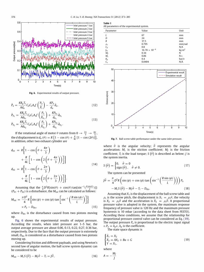
Fig. 6 shows the experimental results of output pressure.According the results, when inlet pressure are 1–5 bar, theoutput average pressure are about 0.06, 0.13, 0.22, 0.27, 0.36 bar,respectively. Due to the face that the output pressure is extremelysmall, Ddis is considered as a disturbance caused from two pistonsmoving up.
Considering friction and different payloads, and using Newton’ssecond law of angular motion, the ball screw system dynamic canbe considered to be
Mtol − McSθ− Mf θ − Tl = J θ , (16)
Table 1All parameters of the experimental system.
Parameter Value Unit
L 67 mmD 24 mmR 37.5 mmρs 0.795 mm/radCd 0.8 N/AJm 16.78 × 10⁻⁴ kg m2
Mf 0.34 NMc 0.06 N sKp 0.4 bar/vCo 0.0404 N/A
Fig. 7. Ball screw table performance under the same inlet pressure.
where θ is the angular velocity; θ represents the angularacceleration; Mc is the stiction coefficient; Mf is the frictioncoefficient; Tl is the load torque; S
θis described as below; J is
the system inertia.
Sθ
=
0, θ = 0sign
θ, θ = 0.
(17)
The system can be presented
J θ =π
4D2R
sin (φ) + cos (φ) tan
sin−1
R sin (φ)
L
Pa
−McSθ− Mf θ − Tl − Ddis. (18)
Assuming that X1 is the displacement of the ball screw table andρs is the screw pitch, the displacement is X1 = ρsθ , the velocityis X2 = ρsθ and the acceleration is X2 = ρsθ . A proportionalpressure valve is adopted in the system, the maximum responsefrequency of pressure valve is 120 Hz and the maximum pressurehysteresis is 10 mbar (according to the data sheet from FESTO).According these conditions, we assume that the relationship forproportional pressure control valve can be considered as Eq. (19).The output pressure Pa is proportional to the electric input signalv.Pa = kpv, kp is the coefficient.
The state space dynamic isX1 = X2
X2 = AX2 + Bu + GY = X1,
(19)
where
A = −Mf
J

C.-H. Lu, Y.-R. Hwang / ISA Transactions 51 (2012) 373–385 377
(a) Position results within 10 s. (b) Position results between 1.25 and 2.75 s.
(c) Output voltages within 10 s.
Fig. 8. Experimental results for the k1 parameter.
B =ρskpJ
πD2
4R
sin (φ) + cos (φ) tan
sin−1
R sin (φ)
L
u = v
G = −ρs
J
McS
X1
ρs
+ Tl + Ddis
.
Mathematical model validation has been verified by comparingthe open loop step dynamic of all ball screw table system responseswhich are obtained from both experiments and simulation.Specifications of the air motor used for the experiment andsimulation are listed in Table 1. The system response for an openloop air motor system is shown in Fig. 7 and the simulated resultsbased on Eq. (19). The performance of the ball screw table withthe 4 bar. The simulated and experimental results are consistent.The different output responses depend on various pressuresand mechanical problems, such as friction, air compressibility,pressure leakage, artificial factors (mechanism assembly), and soon. According to the results the radial piston air motor connectedwith a ball screw table can be considered a second-order system.The dynamics of the system can be described by the following
equation:Eq. (19) can be rearranged as follows:X1 = X2
X2 = (A + 1A) X2 + (B + 1B) u + GY = X1.
(20)
Eq. (20) can be derived to as follows:
X2 = AX2 + Bu + F , (21)
where F is the uncertainty
F = 1AX2 + 1Bu + G, (22)
where |F | ≤ F ; and 1A and 1B are the part of the variable uncer-tainty of the system. The tracking error between the system outputY and the position command signal Yd is defined as
z1 = Y − Yd. (23)
Then
z1 = Y − Yd = X2 − Yd. (24)

378 C.-H. Lu, Y.-R. Hwang / ISA Transactions 51 (2012) 373–385
(a) Position results within 10 s. (b) Position results between 1.25 and 2.75 s.
(c) Output voltages within 10 s.
Fig. 9. Experimental results for the c1 parameter.
(a) Position results within 10 s. (b) Position results between 1.25 and 2.75 s.
Fig. 10. Experimental results for variable k1 and c1 parameters.

C.-H. Lu, Y.-R. Hwang / ISA Transactions 51 (2012) 373–385 379
(a) Position results within 10 s. (b) Position results between 1.5 and 2.75 s.
(c) Output voltages within 10 s.
Fig. 11. Experimental results for the h parameter.
Let
α1 = c1z1, (25)
where c1 is a positive constant.Define the Lyapunov function
V1 =12z21 . (26)
Let z2 = z1 + α1 = X2 − Yd + α1, then
V1 = z1X2 − Yd
= z1 (z2 − α1) = z1z2 − c1z21 , (27)
z2 = X2 − Yd + α1 = AX2 + Bu + F − Yd + α1. (28)
The Lyapunov function is
V2 = V1 +12s2, (29)
where s is the sliding surface.Define the sliding function as follows:
s = k1z1 + z2, (30)
where k1 > 0; then
V2 = V1 + ss = z1z2 − c1z21 + ss
= z1z2 − c1z21 + s (k1z1 + z2)
= z1z2 − c1z21+ s
k1 (z2 − c1z1) + AX2 + Bu + F − Yd + α1
= z1z2 − c1z21 + s
k1 (z2 − c1z1) + A
z2 + Yd − α1
+ Bu + F − Yd + α1
. (31)
The backstepping sliding mode controller can be summarized
u = B−1 −k1 (z2 − c1z1) − A
z2 + Yd − α1
− Fsgn(s) + Yd − α1 − h(s + βsgn(s))
, (32)
where h and β are positive constants.Substitute Eq. (32) into Eq. (31)
V2 = z1z2 − c1z21 − hs2 − hβ|s| + Fs − F |s|
≤ −c1z21 + z1z2 − hs2 − hβ|s| + |s|(|F | − F)
≤ −c1z21 + z1z2 − hs2 − hβ|s|. (33)

380 C.-H. Lu, Y.-R. Hwang / ISA Transactions 51 (2012) 373–385
(a) Tracking position results within 40 s. (b) Tracking position results within 0.75 s.
(c) Tracking error within 40 s. (d) Output voltage within 40 s.
Fig. 12. Experimental tracking sinusoidal wave results with backstepping sliding mode control (h = 20).
Given Q as a positive definite symmetric matrix
Q =
c1 + hk21 hk1 −12
hk1 −12
h
, (34)
then
zTQz =z1 z2
c1 + hk21 hk1 −12
hk1 −12
h
z1 z2
T= c1z21 + hk21z
21 + 2hk1z1z2 − z1z2 + hz22
= c1z21 − z1z2 + hs2, (35)
where z =z1 z2
. Eq. (31) can be written as
V2 ≤ −zTQz − hβ|s|.
Then
|Q | = hc1 + hk21
−
hk1 −
12
2
= hc1 + k1 −
14
. (36)
Due to h, c1, k1 can be chosen that |Q | > 0.
Then
V2 ≤ 0. (37)
Define the following term
W (t) = ZTQZ + hβ|s| ≤ −V2 (z1(t), z2(t)) , (38)
then t
0W (τ ) dτ ≤ V2 (z1 (0) , z2(0)) − V2 (z1(t), z2(t)) . (39)
Since V2 (z1(0), z2(0)) is bounded; V2 (z1(t), z2(t)) is nonin-creasing and bounded, the following result can be concluded:
limt−>∞
t
0W (τ ) dτ < ∞. (40)
Moreover, W (t) is also bonded. However, W (t) is uniformlycontinuous. Using Barbalat’s lemma [17], the following result canbe obtained:
limt−>∞
W (t) = 0. (41)
Therefore, z1 and z2 will converge to zero. The stability ofthe proposed backstepping sliding mode control system can beguaranteed.

C.-H. Lu, Y.-R. Hwang / ISA Transactions 51 (2012) 373–385 381
(a) Tracking position results within 40 s. (b) Tracking position results within 0.75 s.
(c) Tracking error within 40 s. (d) Output voltage within 40 s.
Fig. 13. Experimental tracking sinusoidal wave results with backstepping sliding mode control (h = 30).
The pressure source is a commercial air compressor. Themaximum pressure of this compressor is 5 bar for safetyconsideration so that operation pressure is below 4 bar in thissystem. These experimental initial conditions are designed asfollows: air supply pressure 4 bar for Figs. 8–14 and 16; 3 barfor Fig. 17; position control at 10 mm; loading mass is 15 kg; theamplitude and the frequency of the sinusoidal wave restricted to20 mm and 0.25 Hz, respectively.
The experimental results for these k1, c1 and h parametersare obtained using the previously mentioned control rules andinitial conditions. Fig. 8(b) shows the experimental results forthe backstepping sliding mode controller with k1 adjusted to 30,50 and 70. Because parameter k1 affects the transient response,different k1 has an effect on rising time. Parameter c1 affects theapproach of the sliding surface. The results are shown in Fig. 9(b).When c1 increases gradually, a longer time is needed to approachthe sliding surface. Fig. 10(b) shows the experimental resultsobtained when using different parameter values for k1 and c1. Theparameters value are set as follows: set1: k1 = 50; c1 = 50, set2:k1 = 50; c1 = 30, set3: k1 = 30; c1 = 30; and set4: k1 = 30; c1 =
50. The steady-state response of set3 displays a serious chatteringphenomenon compared to the set2, which are not only relativelystability but also have rising times that remain suitable for the
systembetween set3 and set4. In order to achieve accurate positioncontrol for a pneumatic servo system, the set2 is selected in thecontroller. As shown in Fig. 11(b), the dissimilarity of parameterh affects the various chattering phenomena for the pneumaticsystem. The steady response has a serious chattering phenomenon.The average value of the steady state error is 2.83 µm whenh = 70. In other words, although the steady response has a slightvibration when h = 40 the state error is the best of the otherparameters (h = 10 and h = 70). A comparison of differentparameters h for position control is shown in Table 2.
Table 3 shows results for the different phenomenon obtainedwith the parameter h. Figs. 12–14 shows the sinusoidal wavesobtained when using different h values for backstepping slidingmode controller. However, Fig. 12(b) shows that the slightchattering phenomenon in steady response with an average errorvalue of about 22 µm. The tracking time is nearly 6.3 s when h =
20. When h is adjusted to 40, the steady response shows seriouschattering phenomenon and the average value of error is about32 µm. The tracking time is nearly 1–2 s (the definition of trackingtime is that the system is entering sliding surface when trackingtrajectory). In otherwords, if h decreases, the average value of errorwill decrease, but the tracking time will increase and vice versa.In order to avoid these disadvantages, a combination of the fuzzy

382 C.-H. Lu, Y.-R. Hwang / ISA Transactions 51 (2012) 373–385
(a) Tracking position results within 40 s. (b) Tracking position results within 0.75 s.
(c) Tracking error within 40 s. (d) Output voltage within 40 s.
Fig. 14. Experimental tracking sinusoidal wave results with backstepping sliding mode control (h = 40).
Table 2Comparison of different parameters for position control.
Parameter (h) h = 10 h = 40 h = 70
First experimental result (maximum steady state error) 9 µm 0.5 µm 7 µmSecond experimental result (maximum steady state error) 18 µm 0 µm 1 µmThird experimental result (maximum steady state error) 20.5 µm 0.5 µm 0.5 µmAverage value of steady state error 15.83 µm 0.3 µm 2.83 µmPhenomenon No chattering Slight chattering Serious chattering
Table 3Comparison of different parameters for tracking sinusoidal wave.
Parameter (h) The average value of error (µm) Tracking time Phenomenon
h = 20 About 22 About 6.3 s Slight chatteringh = 30 About 27 About 3 s Chatteringh = 40 About 32 About 1–2 s Serious chattering
control theory and backstepping slidingmode control methodwasproposed here.
4. Parameter h adjustment for the fuzzy controller design
Different chattering phenomena are obtained with differentvalues of parameter h; therefore constant h is not enough to obtain
accurate experimental results for tracking control. Hence, the bestscheme is to adjust the value of parameter h with time so thatthe system does not have a heavy chattering phenomenon and thetracking error can decrease as time goes by. Fuzzy reasoning rulesare adopted to improve the systemperformance in order to achievethis goal.
C.-H. Lu, Y.-R. Hwang / ISA Transactions 51 (2012) 373–385 383
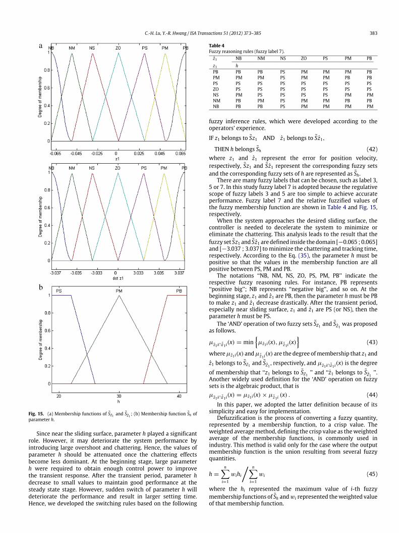
Fig. 15. (a) Membership functions of SZ1 and SZ1 ; (b) Membership function Sh ofparameter h.
Since near the sliding surface, parameter h played a significantrole. However, it may deteriorate the system performance byintroducing large overshoot and chattering. Hence, the values ofparameter h should be attenuated once the chattering effectsbecome less dominant. At the beginning stage, large parameterh were required to obtain enough control power to improvethe transient response. After the transient period, parameter hdecrease to small values to maintain good performance at thesteady state stage. However, sudden switch of parameter h willdeteriorate the performance and result in larger setting time.Hence, we developed the switching rules based on the following
Table 4Fuzzy reasoning rules (fuzzy label 7).z1 NB NM NS ZO PS PM PBz1 hPB PB PB PS PM PM PM PBPM PM PM PS PM PM PB PBPS PS PS PS PS PS PS PSZO PS PS PS PS PS PS PSNS PM PS PS PS PS PM PMNM PB PM PS PM PM PB PBNB PB PB PS PM PM PM PM
fuzzy inference rules, which were developed according to theoperators’ experience.
IF z1 belongs to Sz1 AND z1 belongs to Sz1,
THEN h belongs Sh (42)where z1 and z1 represent the error for position velocity,respectively, Sz1 and Sz1 represent the corresponding fuzzy setsand the corresponding fuzzy sets of h are represented as Sh.
There are many fuzzy labels that can be chosen, such as label 3,5 or 7. In this study fuzzy label 7 is adopted because the regulativescope of fuzzy labels 3 and 5 are too simple to achieve accurateperformance. Fuzzy label 7 and the relative fuzzified values ofthe fuzzy membership function are shown in Table 4 and Fig. 15,respectively.
When the system approaches the desired sliding surface, thecontroller is needed to decelerate the system to minimize oreliminate the chattering. This analysis leads to the result that thefuzzy set Sz1 and Sz1 are defined inside thedomain [−0.065 ; 0.065]and [−3.037 ; 3.037] tominimize the chattering and tracking time,respectively. According to the Eq. (35), the parameter h must bepositive so that the values in the membership function are allpositive between PS, PM and PB.
The notations ‘‘NB, NM, NS, ZO, PS, PM, PB’’ indicate therespective fuzzy reasoning rules. For instance, PB represents‘‘positive big’’; NB represents ‘‘negative big’’, and so on. At thebeginning stage, z1 and z1 are PB, then the parameter hmust be PBto make z1 and z1 decrease drastically. After the transient period,especially near sliding surface, z1 and z1 are PS (or NS), then theparameter h must be PS.
The ‘AND’ operation of two fuzzy sets SZ1 and SZ1 was proposedas follows.
µz1 i∩˜z1 i(x) = min
µz1i(x), µ ˜z1 i
(x)
(43)
whereµz1 i(x) andµ ˜z1 i(x) are the degree ofmembership that z1 and
z1 belongs to SZ1 and SZ1 , respectively, and µz1 i∩˜z1 i(x) is the degree
of membership that ‘‘z1 belongs to SZ1 ’’ and ‘‘z1 belongs to SZ1 ’’.Another widely used definition for the ‘AND’ operation on fuzzysets is the algebraic product, that isµz1 i∩˜z1 i
(x) = µz1 i(x) × µ ˜z1 i(x) . (44)
In this paper, we adopted the latter definition because of itssimplicity and easy for implementation.
Defuzzification is the process of converting a fuzzy quantity,represented by a membership function, to a crisp value. Theweighted averagemethod, defining the crisp value as theweightedaverage of the membership functions, is commonly used inindustry. This method is valid only for the case where the outputmembership function is the union resulting from several fuzzyquantities.
h =
ni=1
wihi
ni=1
wi (45)
where the hi represented the maximum value of i-th fuzzymembership functions of Sh andwi represented theweighted valueof that membership function.
384 C.-H. Lu, Y.-R. Hwang / ISA Transactions 51 (2012) 373–385
(a) Tracking position results within 40 s. (b) Tracking position results within 0.75 s.
(c) Tracking error within 40 s. (d) Output voltage within 40 s.
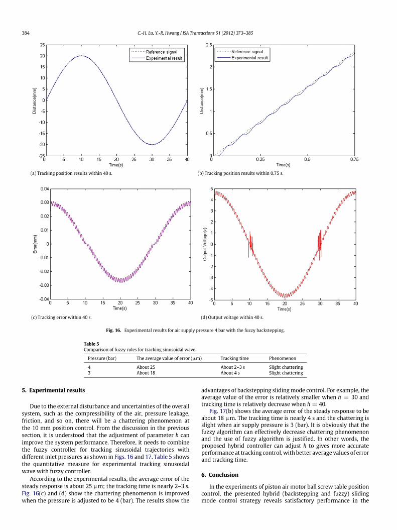
Fig. 16. Experimental results for air supply pressure 4 bar with the fuzzy backstepping.
Table 5Comparison of fuzzy rules for tracking sinusoidal wave.
Pressure (bar) The average value of error (µm) Tracking time Phenomenon
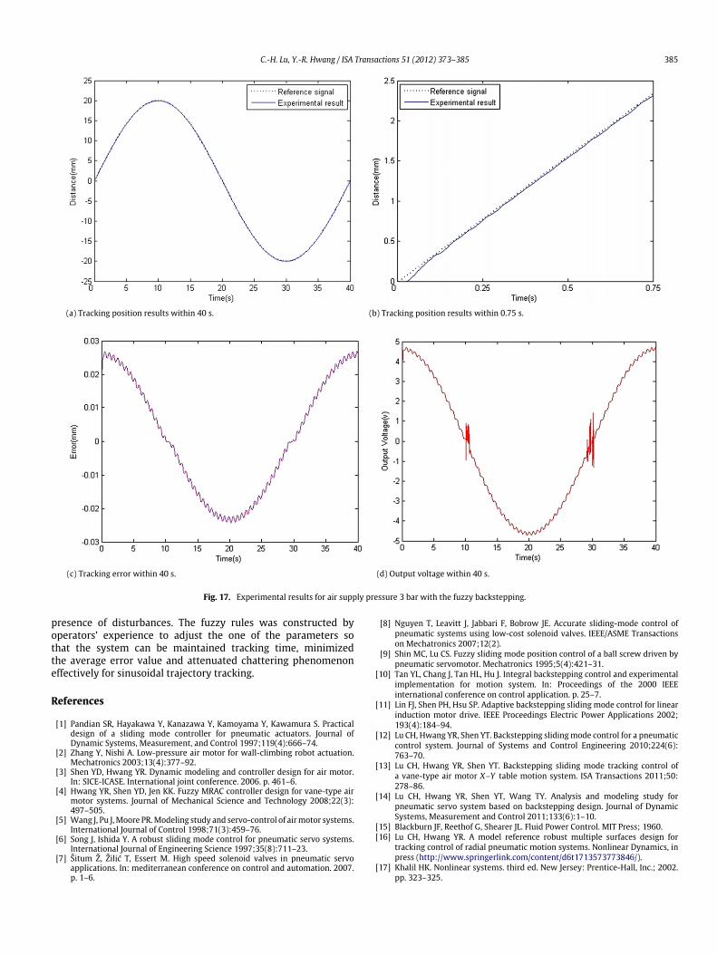
4 About 25 About 2–3 s Slight chattering3 About 18 About 4 s Slight chattering
5. Experimental results
Due to the external disturbance and uncertainties of the overallsystem, such as the compressibility of the air, pressure leakage,friction, and so on, there will be a chattering phenomenon atthe 10 mm position control. From the discussion in the previoussection, it is understood that the adjustment of parameter h canimprove the system performance. Therefore, it needs to combinethe fuzzy controller for tracking sinusoidal trajectories withdifferent inlet pressures as shown in Figs. 16 and 17. Table 5 showsthe quantitative measure for experimental tracking sinusoidalwave with fuzzy controller.
According to the experimental results, the average error of thesteady response is about 25 µm; the tracking time is nearly 2–3 s.Fig. 16(c) and (d) show the chattering phenomenon is improvedwhen the pressure is adjusted to be 4 (bar). The results show the
advantages of backstepping slidingmode control. For example, theaverage value of the error is relatively smaller when h = 30 andtracking time is relatively decrease when h = 40.
Fig. 17(b) shows the average error of the steady response to beabout 18 µm. The tracking time is nearly 4 s and the chattering isslight when air supply pressure is 3 (bar). It is obviously that thefuzzy algorithm can effectively decrease chattering phenomenonand the use of fuzzy algorithm is justified. In other words, theproposed hybrid controller can adjust h to gives more accurateperformance at tracking control,with better average values of errorand tracking time.
6. Conclusion
In the experiments of piston air motor ball screw table positioncontrol, the presented hybrid (backstepping and fuzzy) slidingmode control strategy reveals satisfactory performance in the
C.-H. Lu, Y.-R. Hwang / ISA Transactions 51 (2012) 373–385 385
(a) Tracking position results within 40 s. (b) Tracking position results within 0.75 s.
(c) Tracking error within 40 s. (d) Output voltage within 40 s.
Fig. 17. Experimental results for air supply pressure 3 bar with the fuzzy backstepping.
presence of disturbances. The fuzzy rules was constructed byoperators’ experience to adjust the one of the parameters sothat the system can be maintained tracking time, minimizedthe average error value and attenuated chattering phenomenoneffectively for sinusoidal trajectory tracking.
References
[1] Pandian SR, Hayakawa Y, Kanazawa Y, Kamoyama Y, Kawamura S. Practicaldesign of a sliding mode controller for pneumatic actuators. Journal ofDynamic Systems, Measurement, and Control 1997;119(4):666–74.
[2] Zhang Y, Nishi A. Low-pressure air motor for wall-climbing robot actuation.Mechatronics 2003;13(4):377–92.
[3] Shen YD, Hwang YR. Dynamic modeling and controller design for air motor.In: SICE-ICASE. International joint conference. 2006. p. 461–6.
[4] Hwang YR, Shen YD, Jen KK. Fuzzy MRAC controller design for vane-type airmotor systems. Journal of Mechanical Science and Technology 2008;22(3):497–505.
[5] Wang J, Pu J,Moore PR.Modeling study and servo-control of airmotor systems.International Journal of Control 1998;71(3):459–76.
[6] Song J, Ishida Y. A robust sliding mode control for pneumatic servo systems.International Journal of Engineering Science 1997;35(8):711–23.
[7] Šitum Ž, Žilić T, Essert M. High speed solenoid valves in pneumatic servoapplications. In: mediterranean conference on control and automation. 2007.p. 1–6.
[8] Nguyen T, Leavitt J, Jabbari F, Bobrow JE. Accurate sliding-mode control ofpneumatic systems using low-cost solenoid valves. IEEE/ASME Transactionson Mechatronics 2007;12(2).
[9] Shin MC, Lu CS. Fuzzy sliding mode position control of a ball screw driven bypneumatic servomotor. Mechatronics 1995;5(4):421–31.
[10] Tan YL, Chang J, Tan HL, Hu J. Integral backstepping control and experimentalimplementation for motion system. In: Proceedings of the 2000 IEEEinternational conference on control application. p. 25–7.
[11] Lin FJ, Shen PH, Hsu SP. Adaptive backstepping sliding mode control for linearinduction motor drive. IEEE Proceedings Electric Power Applications 2002;193(4):184–94.
[12] Lu CH, Hwang YR, Shen YT. Backstepping slidingmode control for a pneumaticcontrol system. Journal of Systems and Control Engineering 2010;224(6):763–70.
[13] Lu CH, Hwang YR, Shen YT. Backstepping sliding mode tracking control ofa vane-type air motor X–Y table motion system. ISA Transactions 2011;50:278–86.
[14] Lu CH, Hwang YR, Shen YT, Wang TY. Analysis and modeling study forpneumatic servo system based on backstepping design. Journal of DynamicSystems, Measurement and Control 2011;133(6):1–10.
[15] Blackburn JF, Reethof G, Shearer JL. Fluid Power Control. MIT Press; 1960.[16] Lu CH, Hwang YR. A model reference robust multiple surfaces design for
tracking control of radial pneumatic motion systems. Nonlinear Dynamics, inpress (http://www.springerlink.com/content/d6t1713573773846/).
[17] Khalil HK. Nonlinear systems. third ed. New Jersey: Prentice-Hall, Inc.; 2002.pp. 323–325.


![NORTA MIT PRESENTATION.pptx [Read-Only] · • Centrifugal pumps • Side channel pumps • Gear pumps • Screw pumps • Single screw pumps • Piston pumps • Vacuum pumps •](https://img.dokumen.tips/doc/110x75/5ec27ab9e3ef591d10504c3a/norta-mit-read-only-a-centrifugal-pumps-a-side-channel-pumps-a-gear-pumps.jpg)