Embed Size (px)
Citation preview

Hybrid Simulations: Theory and Applications in Earthquake Engineering
Khalid M. Mosalam, ProfessorDirector of nees@berkeley
Structural Engineering, Mechanics, and MaterialsDepartment of Civil and Environmental EngineeringUniversity of California, Berkeley
Seminar in Minho University, Guimarães, Portugal
1

Seminar on Recent Advances & Directions in Earthquake Eng., Minho Univ., Portugal, Oct. 2012 2
AcknowledgementsDr. Selim Günay, UCBDr. Shakhzod Takhirov, UCBMr. Mohamed Moustafa, UCBMr. Ahmed Bakhaty, UCBMr. Eric Fujisaki, PG&ESponsors:• California Institute for Energy and Environment (CIEE)• US-DoE• PG&E• National Science Foundation (NSF) [PEER; NEES]

Seminar on Recent Advances & Directions in Earthquake Eng., Minho Univ., Portugal, Oct. 2012
Introduction
15 sites
10th
http://nees.org
3
http://nees.berkeley.eduAll our presentation from Oct. 1-4, 2012 will be made available in this site

Seminar on Recent Advances & Directions in Earthquake Eng., Minho Univ., Portugal, Oct. 2012
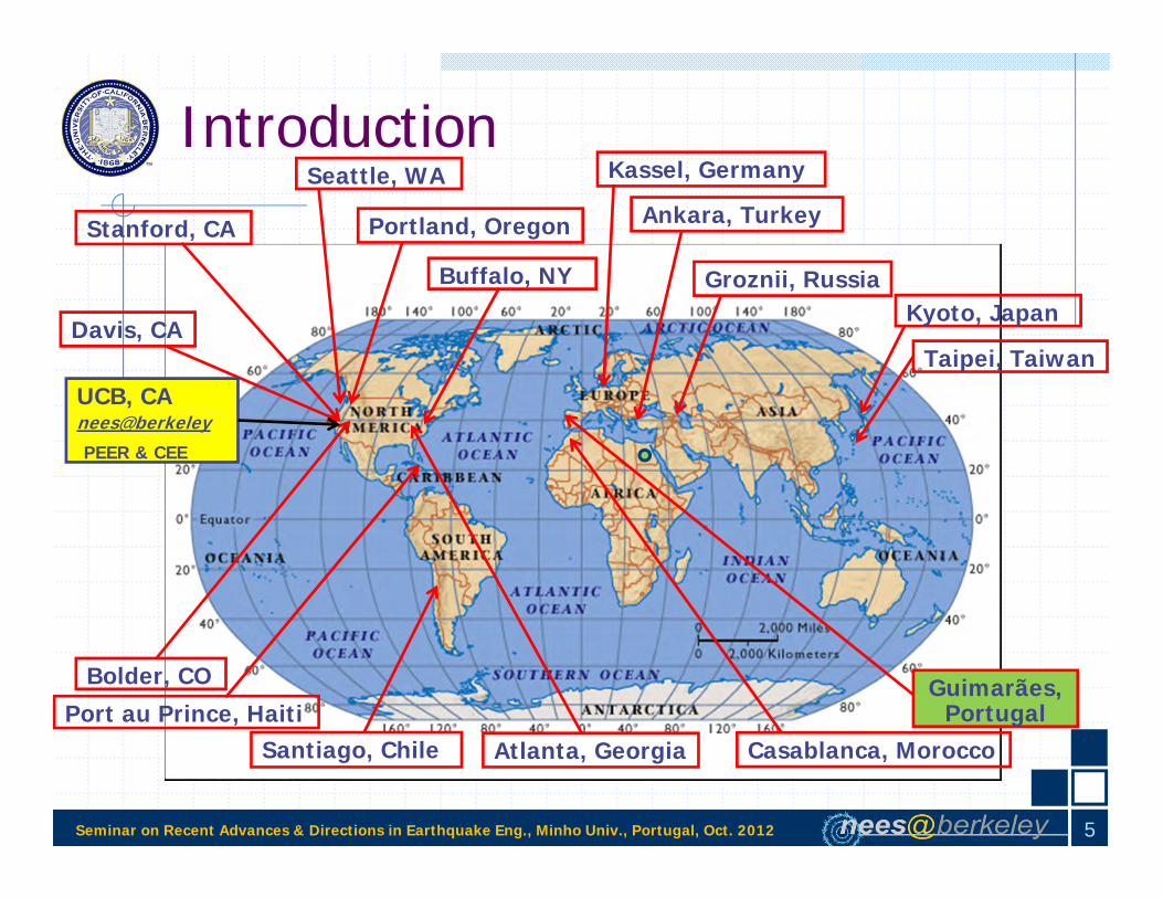
Introduction
4
http://nees.berkeley.edu
Seminar on Recent Advances & Directions in Earthquake Eng., Minho Univ., Portugal, Oct. 2012
Introduction
Kyoto, Japan
Port au Prince, Haiti
Groznii, Russia
Portland, OregonStanford, CA
Davis, CA
Buffalo, NY
Bolder, CO
Atlanta, Georgia
UCB, CAnees@berkeleyPEER & CEE
Taipei, Taiwan
Ankara, Turkey
Casablanca, MoroccoSantiago, Chile
Kassel, Germany
Guimarães, Portugal
Seattle, WA
5

Seminar on Recent Advances & Directions in Earthquake Eng., Minho Univ., Portugal, Oct. 2012
Mini-Symposium on Hybrid Simulation: Theory and Applications [Tomorrow]
6
1. Hybrid simulation fundamentals [3.0 hours]1. Substructuring2. Integration methods 3. Simulation errors
2. Hybrid simulation applications [2.5 hours] 1. Introduction to OpenSees2. Introduction to OpenFresco3. Application I: Hybrid simulation of structural insulated panels4. Application II: Real-time hybrid simulation of high voltage electric disconnect
switches 3. Seismic testing of lifelines related to the electric grid [1.5 hours]
1. Shaking table and static tests and finite element simulations of high voltage electric disconnect switches
2. Fragility tests of concrete duct-banks for high voltage distribution lines 4. Use of advanced monitoring (e.g. Laser scanning in Haiti) and
measurement systems in structural testing [1.0 hour]
https://peercenter.wufoo.com/forms/hybrid-simulation-workshop-evaluation-portugal/We would like your feedback via the electronic form set especially for this workshop on the link below:

Seminar on Recent Advances & Directions in Earthquake Eng., Minho Univ., Portugal, Oct. 2012
Short Course on Probabilistic Performance-based Earthquake Engineering (PBEE) [Oct. 3-4]
7
Pacific Earthquake Engineering Research (PEER) Center Mission
Advance and apply PBEE tools to meet the needs of various stakeholders
Problem-focused, multi-disciplinary research built upon foundation of engineering and scientific fundamentals
Close partnerships with government, industry and engineering professionals
Strong national and global research collaborations
Commitment to education at all levels
Courtesy of Prof. S. Mahin

Seminar on Recent Advances & Directions in Earthquake Eng., Minho Univ., Portugal, Oct. 2012
Short Course on Probabilistic Performance-based Earthquake Engineering (PBEE) [Oct. 3-4]
8
1. PBEE assessment methods [2.0 hours]1. Conditional probability approaches such as PEER and SAC/FEMA formulations 2. Unconditional probabilistic approach
2. PBEE design methods [2.0 hours] 1. Optimization-based methods 2. Non-optimization-based methods
3. PEER PBEE formulation [4.0 hours]1. Hazard analysis2. Structural analysis3. Damage analysis4. Loss analysis5. Combination of analyses
4. Application 1: Evaluation of the effect of unreinforced masonry infill wall on reinforced concrete frames with probabilistic PBEE [1.0 hour]
5. Application 2: Evaluation of the seismic response of structural insulated panels with probabilistic PBEE [1.0 hours]
6. Application 3: PEER PBEE assessment of a shear-wall building located on the University of California, Berkeley campus [1.0 hours]
7. Future extension to multi-objective performance-based sustainable design [0.5 hour]8. Recapitulation [0.5 hour]

Hybrid Simulations: Theory and Applications in Earthquake Engineering
Khalid M. Mosalam, ProfessorDirector of nees@berkeley
Structural Engineering, Mechanics, and MaterialsDepartment of Civil and Environmental EngineeringUniversity of California, Berkeley
Seminar in Minho University, Guimarães, Portugal
9

Seminar on Recent Advances & Directions in Earthquake Eng., Minho Univ., Portugal, Oct. 2012
Outline
1. Motivation2. Theory
a) Backgroundb) Substructuringc) Integration Methodsd) Simulation Errorse) Geographically Distributed HSf) Real-time HS
3. Application I: HS of Structural Insulated Panels (SIPs)4. Application II: RTHS of Electrical Insulator Posts on a
Smart Shaking Table5. Future Directions
10

Seminar on Recent Advances & Directions in Earthquake Eng., Minho Univ., Portugal, Oct. 2012
Motivation
11
0 10 20 30 40 50-6
-4
-20
2
4
6
Time [sec]
Acc
eler
atio
n [g
]
-6
-4
-20
2
4
6
Acc
eler
atio
n [g
]
0 10 20 30 40 50-6
-4
-20
2
4
6
Time [sec]
-6
-4
-20
2
4
6
Top of support structure: Real-time HS
Top of support structure: Conventional shaking table
Top of insulator: Real-time HS
Top of insulator: Conventional shaking table
$$$
$
We will see this again today and in tomorrow’s HS workshop!
Seminar on Recent Advances & Directions in Earthquake Eng., Minho Univ., Portugal, Oct. 2012
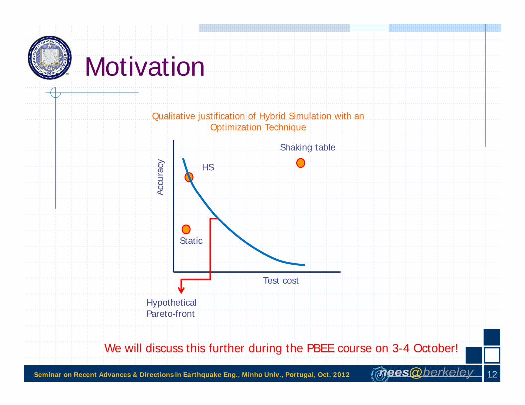
Motivation
12
We will discuss this further during the PBEE course on 3-4 October!
Qualitative justification of Hybrid Simulation with an Optimization Technique
Accu
racy
Test cost
Hypothetical Pareto-front
HS
Shaking table
Static

Seminar on Recent Advances & Directions in Earthquake Eng., Minho Univ., Portugal, Oct. 2012
Theory: Background Physical models of structural resistance Computer models of structural damping and inertia
m: massk: spring constantc: damping coefficient
mk
c
f(t)=-mag
d
m ac vk d
f(t)m a + c v + k d = -m ag
m a + c v + R = -m ag
m a + m ag + c v = -R
13

Seminar on Recent Advances & Directions in Earthquake Eng., Minho Univ., Portugal, Oct. 2012
Theory: Background
Dynamics ofthe system
Physicalmodel,
e.g. 3dof
Feedbackdynamics
Error in current position
Desiredd(t) +
-
Forcevalue
Current position
d(t)
m1 m2 m3
Need to assemble:a) Restoring forces (Geometric stiffness may be considered, )b) Damping forces from physical dampersc) Inertia forces from the mass of the physical specimens
dKRR G
14

Seminar on Recent Advances & Directions in Earthquake Eng., Minho Univ., Portugal, Oct. 2012
Theory: Background
By definition, a hybrid model is sub-structured Multiple sub-structures can be used Many analytical sub-structures (Soft models) Many physical sub-structures (Hard model)
15

Seminar on Recent Advances & Directions in Earthquake Eng., Minho Univ., Portugal, Oct. 2012
Theory: Background Testing infrastructure must enable:
1. Simulation of individual sub-structures2. Integration of equations of motion
16

Seminar on Recent Advances & Directions in Earthquake Eng., Minho Univ., Portugal, Oct. 2012
Theory: Background
Advantages:1. Physical model resistance of sub-structures whose computer
models are not good enough.2. Model the inertia forces (and damping, and second-order
effects) in the computer.
Disadvantages:1. Substructures are connected and interact at their boundaries.2. Specimens have inertia and damping, too.
17

Seminar on Recent Advances & Directions in Earthquake Eng., Minho Univ., Portugal, Oct. 2012
Theory: Background
cg
pg
cccp
pcpp
c
p
c
p
cccp
pcpp
c
p
cccp
pcpp
aa
mmmm
RR
vv
cccc
aa
mmmm
Restoring forces can be assembled
Also the following can be assembled:1. Damping forces from physical dampers2. Inertia forces from the mass of the physical specimens
Subscript c computed sub-structureSubscript p physical sub-structure
18

Seminar on Recent Advances & Directions in Earthquake Eng., Minho Univ., Portugal, Oct. 2012
Theory: Background
Damping and inertia:1. Explicit consideration of physical dampers and physical masses, based on measured
velocities and accelerations.2. DOF condensation must be performed carefully.3. Coordinate transformations must be propagated to velocities and accelerations.
Second-order effects:Geometric stiffness may be assembled into the resistance:
dKRR G
19

Seminar on Recent Advances & Directions in Earthquake Eng., Minho Univ., Portugal, Oct. 2012
Theory: BackgroundInterface between Sub-Structures Equilibrium and compatibility must be satisfied Deformations and forces
1. Displacement (relatively easy)2. Rotation (very difficult)
Opportunity to do:DOF condensation
Coordinate transformationsPhysical to computational DOF’s: dp=Tdc
Geometry correctionsActuator movements
20

Seminar on Recent Advances & Directions in Earthquake Eng., Minho Univ., Portugal, Oct. 2012
Theory: Background
Distributed Hybrid Simulation
T. Yang, B. Stojadinovic, & J. Moehle
21

Seminar on Recent Advances & Directions in Earthquake Eng., Minho Univ., Portugal, Oct. 2012
Theory: Background
Pan, P., Tomofuji, H., Wang, T., Nakashima, M., Ohsaki, M., & Mosalam, K.M., “Development of Peer-to-Peer (P2P) Internet Online Hybrid Test System,” EESD, 35: 867-890, 2006.
22

Seminar on Recent Advances & Directions in Earthquake Eng., Minho Univ., Portugal, Oct. 2012
Theory: Background
Computed or measured reactions
Pan, P., Tomofuji, H., Wang, T., Nakashima, M., Ohsaki, M., & Mosalam, K.M., “Development of Peer-to-Peer (P2P) Internet Online Hybrid Test System,” EESD, 35: 867-890, 2006.
23

Seminar on Recent Advances & Directions in Earthquake Eng., Minho Univ., Portugal, Oct. 2012
Theory: Background
Pan, P., Tomofuji, H., Wang, T., Nakashima, M., Ohsaki, M., & Mosalam, K.M., “Development of Peer-to-Peer (P2P) Internet Online Hybrid Test System,” EESD, 35: 867-890, 2006.
Proxy Server: a computer system acts as an intermediary for requests from clients seeking resources from other servers.TCP/IP: Transmission Control Protocol and Internet Protocol, networking communications protocols for the Internet.
24

Seminar on Recent Advances & Directions in Earthquake Eng., Minho Univ., Portugal, Oct. 2012
Theory: Substructuringu2
u1
Experimental substructure
Analytical substructure
m2
m1
g2
1
2
1
2221
1211
2
1
2
1 umm
uu
cccc
uu
m00m
a
ea
fff
MeasuredComputed
(-)
Nature of the problem requires substructuring
Presence of experimental substructures requires the use of special integration methods
Presence of a transfer system introduces simulation errors
Rate dependent materials require real-time hybrid simulation (RTHS)
Making use of multiple labs extends the method to geographically distributed testing
25

Seminar on Recent Advances & Directions in Earthquake Eng., Minho Univ., Portugal, Oct. 2012
Theory: Substructuring
Dermitzakis and Mahin (1985)
Nakashima, Kaminosono, Ishida, and Ando (1990)
Schneider and Roeder (1994)
Nakashima and Masaoka (1999)
Mosqueda, Cortes-Delgado, Wang, and Nakashima (2010)
26

Seminar on Recent Advances & Directions in Earthquake Eng., Minho Univ., Portugal, Oct. 2012
Theory: SubstructuringCASE 1: CANTILEVER COLUMN with MASS [No MASS
MOMENT of INERTIA or ANALYTICAL SUBSTRUCTURE]
Red : ExperimentalBlue: Analytical
u1
m1u1
m1
27

Seminar on Recent Advances & Directions in Earthquake Eng., Minho Univ., Portugal, Oct. 2012
Theory: SubstructuringCASE 2: CANTILEVER COLUMN with MASS and MASS
MOMENT of INERTIA [No ANALYTICAL SUBSTRUCTURE]
Red : ExperimentalBlue: Analytical
u1m1, Im1
u2
u1m1, Im1
u2
28

Seminar on Recent Advances & Directions in Earthquake Eng., Minho Univ., Portugal, Oct. 2012
Theory: SubstructuringCASE 3: TWO COLUMNS without
ANALYTICAL SUBSTRUCTURE
Red : ExperimentalBlue: Analytical
u1
u2
m1
m2
u1
u2
m1
m2
29

Seminar on Recent Advances & Directions in Earthquake Eng., Minho Univ., Portugal, Oct. 2012
Theory: SubstructuringCASE 4: TWO COLUMNS with an EXPERIMENTAL
and an ANALYTICAL SUBSTRUCTURE
Red : ExperimentalBlue: Analytical
u1
u2
m1
m2
u3
u4
u1
u2
m1
m2
u3
u4
30

Seminar on Recent Advances & Directions in Earthquake Eng., Minho Univ., Portugal, Oct. 2012
Theory: SubstructuringCASE 4-1: TWO COLUMNS with an EXPERIMENTAL
and an ANALYTICAL SUBSTRUCTURE
Red : ExperimentalBlue: Analytical
u1
u2
m1
m2
u2 - u1
m1
m2
u3u3
31

Seminar on Recent Advances & Directions in Earthquake Eng., Minho Univ., Portugal, Oct. 2012
Theory: SubstructuringCASE 4-2: TWO COLUMNS with an EXPERIMENTAL
and an ANALYTICAL SUBSTRUCTURE
Red : ExperimentalBlue: Analytical
u1
u2
m1
m2
Spring with a lateralforce-deformation relationship
m1
m2 u2 - u1
Spring with a lateralforce-deformation relationship
32

Seminar on Recent Advances & Directions in Earthquake Eng., Minho Univ., Portugal, Oct. 2012
Theory: Substructuring
CASE 5: PORTAL FRAME with one of the COLUMNS and BEAM as ANALYTICAL SUBSTRUCTURE
Red : ExperimentalBlue: Analytical
u1
m1u2
u1
u2m1
33

Seminar on Recent Advances & Directions in Earthquake Eng., Minho Univ., Portugal, Oct. 2012
Theory: SubstructuringCASE 6: MULTI-BAY MULTI-STORY FRAME with
ANALYTICAL SUBSTRUCTURING
Red : ExperimentalBlue: Analytical
m1
m2
u1
u2
34

Seminar on Recent Advances & Directions in Earthquake Eng., Minho Univ., Portugal, Oct. 2012
Theory: SubstructuringCASE 6: MULTI-BAY MULTI-STORY FRAME with
ANALYTICAL SUBSTRUCTURING
Red : ExperimentalBlue: Analytical
m1
m2
u1
u2
35

Seminar on Recent Advances & Directions in Earthquake Eng., Minho Univ., Portugal, Oct. 2012
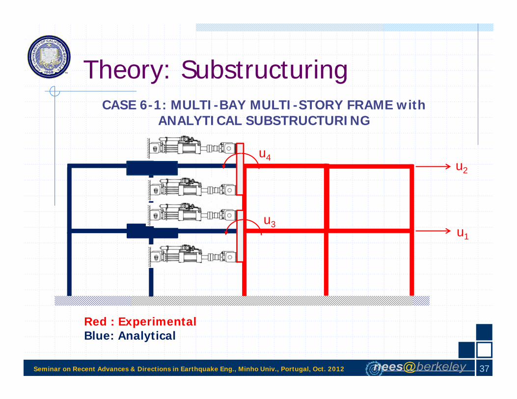
Theory: SubstructuringCASE 6-1: MULTI-BAY MULTI-STORY FRAME with
ANALYTICAL SUBSTRUCTURING
Red : ExperimentalBlue: Analytical
m1
m2
u1
u2
u4
u3
36
Seminar on Recent Advances & Directions in Earthquake Eng., Minho Univ., Portugal, Oct. 2012
Theory: SubstructuringCASE 6-1: MULTI-BAY MULTI-STORY FRAME with
ANALYTICAL SUBSTRUCTURING
Red : ExperimentalBlue: Analytical
m1
m2
u1
u2
u4
u3
37

Seminar on Recent Advances & Directions in Earthquake Eng., Minho Univ., Portugal, Oct. 2012
Theory: Integration MethodsA straightforward integration application: Explicit Newmark Integration
g2
1
2
1
2221
1211
2
1
2
1 umm
uu
cccc
uu
m00m
a
ea
fff
u2
u1
Experimental substructure
Analytical substructure
m2
m1
pfucum
m u c u f p
1. Determine the initial values of response variables: 000 ,, uuu 2. Calculate the effective mass: cmm γΔteff
Δt: integration time step, : integration parameter 3. For each time step i; 1 ≤ i ≤ N, N: total number of steps
a. Compute the displacement: 1-i2
1-i1-ii 2ΔtΔt uuuu b1. Compute the force i,af corresponding to the displacement i1,i2, uu from the constitutive
relationship of the analytical spring b2. Apply the displacement i1,u to the experimental spring and measure the corresponding force i,ef
b3. Determine if from i,ef and i,af by using the equation for f in Eq. 3
c. Compute the predicted velocity: 1-i1-ii γ1Δt~ uuu
d. Compute the effective force: iiieff~ucfpp
e. Compute the acceleration by solving the linear system of equations: effieff pum
f. Compute the velocity: iii γΔt~ uuu g. Increment i and go to step a
38

Seminar on Recent Advances & Directions in Earthquake Eng., Minho Univ., Portugal, Oct. 2012
Theory: Integration MethodsThe most common integration for pure numerical case: Implicit Newmark
F
δ
titi+1
A B
ti
ti+1
A
Bk=2
k=1
F
δ
ti
ti+1
A
Bk=1
k=2
F
Nonuniform displacement increments: velocity and acceleration oscillations within the step
δ Displacement overshoot: artificial unloading
F
δ
titi+1
A B
Iterations may not converge !
Not suitable for hybrid simulation
39

Seminar on Recent Advances & Directions in Earthquake Eng., Minho Univ., Portugal, Oct. 2012
Theory: Integration MethodsThe most common integration for pure numerical case: Implicit NewmarkHS compatible alternatives:
Implicit Newmark Integration with Fixed Number of Iterations Uniform displacement increments Number of iterations constant No convergence problems Number of iterations should be determined with prior analyses Very suitable for slow hybrid simulation with restricted use in real-time hybrid simulation
Alpha-Operator Splitting (OS) Method Tangential stiffness matrix not required Iterations are not required (one predictor & one corrector) No convergence problems Computationally efficient Numerical damping present Very suitable for slow and real-time hybrid simulation for softening systems
Explicit Newmark Integration Initial and tangential stiffness matrices not required Iterations are not required No convergence problems Computationally very efficient No numerical damping Conditionally stable Very suitable for slow and real-time hybrid simulation when stability criterion is met
40

Seminar on Recent Advances & Directions in Earthquake Eng., Minho Univ., Portugal, Oct. 2012
Theory: Simulation Errors
ERROR SOURCES
Errors due to Structural Modeling
Errors due to Numerical Methods
Experimental Errors: 1) Random or 2) Systematic
Errors due to numerical solution nature of HS
41

Seminar on Recent Advances & Directions in Earthquake Eng., Minho Univ., Portugal, Oct. 2012
Theory: Simulation Errors
Measurement errors (Errors in load cells & displacement transducers of actuators)
Calibration
Friction or slippage (gaps) in the attachments
A/D and D/A conversion (Digital controllers & digital transducers for improved accuracy)
Hybrid simulation technique (ramp and hold, continuous, real-time)
Servo-hydraulic closed control loop
Systematic errors:
No distinguishable pattern & generally no specific physical effects are anticipated
Random electrical noise in wires and electronic systems
Random rounding-off or truncation in the A/D conversion of electrical signals
Random noise in measured forces is problematic excites spurious response in higher modes
Random errors:
42
Seminar on Recent Advances & Directions in Earthquake Eng., Minho Univ., Portugal, Oct. 2012
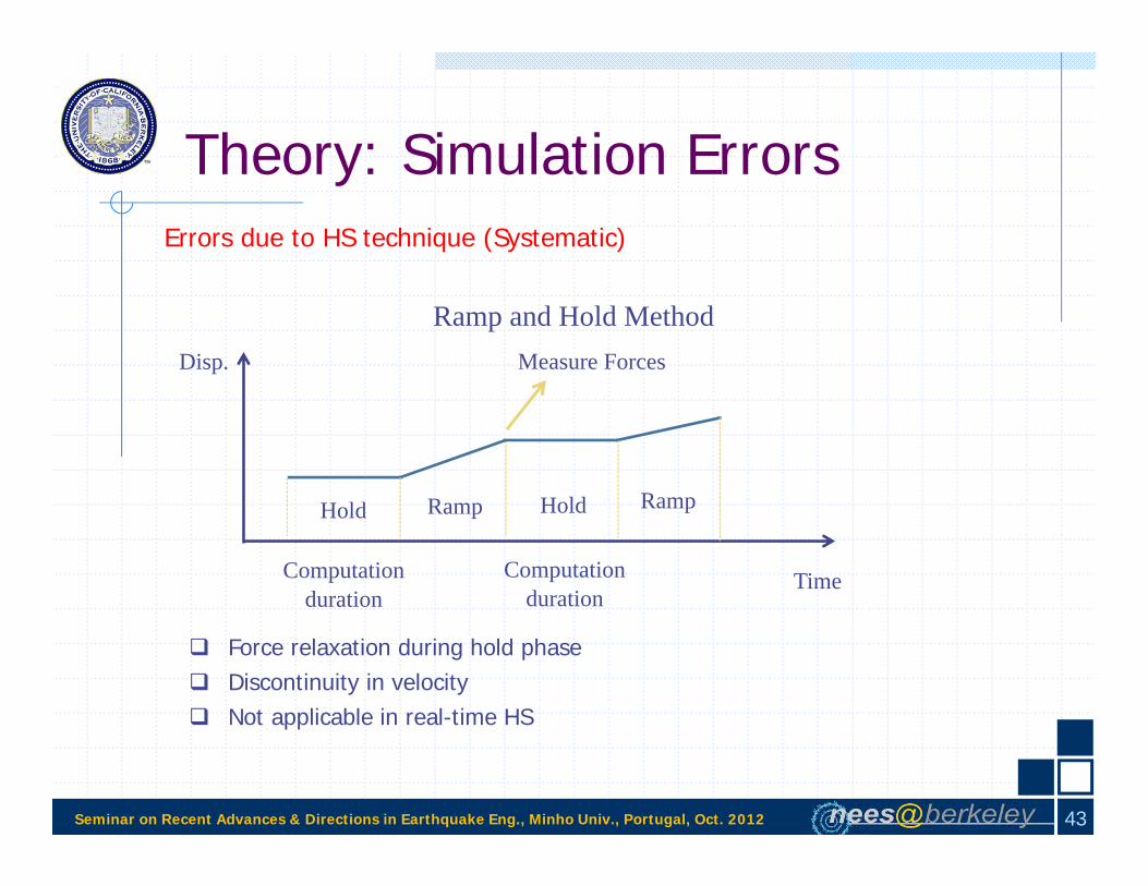
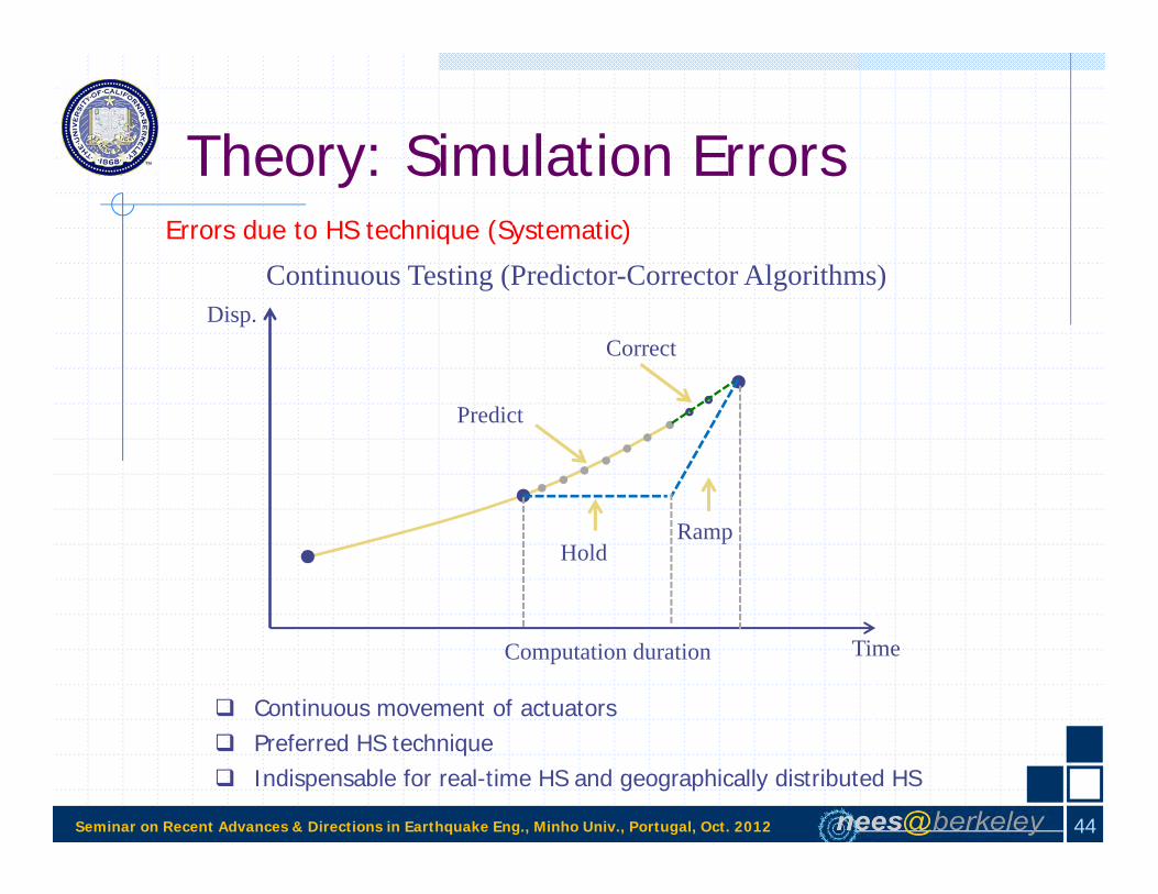
Theory: Simulation ErrorsErrors due to HS technique (Systematic)
Ramp and Hold Method
Time
Disp.
Computation duration
Hold Ramp
Measure Forces
Hold Ramp
Computation duration
Force relaxation during hold phase Discontinuity in velocity Not applicable in real-time HS
43
Seminar on Recent Advances & Directions in Earthquake Eng., Minho Univ., Portugal, Oct. 2012
Theory: Simulation ErrorsErrors due to HS technique (Systematic)
Predict
Correct
HoldRamp
Time
Disp.Continuous Testing (Predictor-Corrector Algorithms)
Computation duration
Continuous movement of actuators Preferred HS technique Indispensable for real-time HS and geographically distributed HS
44

Seminar on Recent Advances & Directions in Earthquake Eng., Minho Univ., Portugal, Oct. 2012
Theory: Simulation Errors
Control loop errors (Systematic)
Actuator dynamics
Servo-valve
Hydraulic power-supply
Control-loop dynamics
Inherent lag in the displacement response
PIDF gains
45

Seminar on Recent Advances & Directions in Earthquake Eng., Minho Univ., Portugal, Oct. 2012
Theory: Simulation ErrorsControl loop errors (Systematic)
• Integration: Command displacement & measured force• True behavior: Measured displacement & measured force
Command Overshoot
Measured force
Increased Damping
Overshooting
Displacement
Restoring Force
Restoring Force
Displacement
Negative Damping
&Instability
Undershooting or delay
Displacement
Restoring Force
46

Seminar on Recent Advances & Directions in Earthquake Eng., Minho Univ., Portugal, Oct. 2012
Theory: Simulation ErrorsControl loop errors (Systematic)
ΔF (lower mode)
Displacement
Restoring Force
ΔF (higher mode)
lower mode
higher mode Cumulative errors increase with ωΔt (Shing and Mahin, 1983)
CommandUndershoot
• Integration methods which introduce numerical damping to suppress the excitation of higher modes can be used to overcome the effects of these errors
• Adaptive minimal control synthesis (MCS) algorithm which provides adaptive gain settingsas the test specimen properties change can be used instead of PID control algorithm
• Integration: Command displacement & measured force• True behavior: Measured displacement & measured force
47
Seminar on Recent Advances & Directions in Earthquake Eng., Minho Univ., Portugal, Oct. 2012
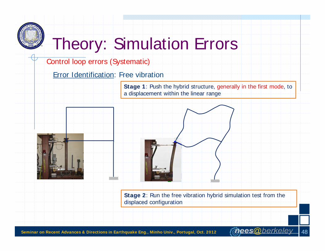
Theory: Simulation ErrorsControl loop errors (Systematic)
Stage 1: Push the hybrid structure, generally in the first mode, to a displacement within the linear range
Stage 2: Run the free vibration hybrid simulation test from the displaced configuration
Error Identification: Free vibration
48

Seminar on Recent Advances & Directions in Earthquake Eng., Minho Univ., Portugal, Oct. 2012
Theory: Simulation ErrorsControl loop errors (Systematic)
Error Identification: Free vibration
Com
pute
d di
spla
cem
ent [
in.]
Time [sec]
Free VibrationPushover
No error
Overshoot
Undershoot or lag
49

Seminar on Recent Advances & Directions in Earthquake Eng., Minho Univ., Portugal, Oct. 2012
Theory: Geographically Distributed HS
Lab 1 in The Americas Lab 2 in Asia
Lab 3 in Europe Lab 4 in Australia
Pan, P., Tomofuji, H., Wang, T., Nakashima, M., Ohsaki, M., & Mosalam, K.M., “Development of Peer-to-Peer (P2P) Internet Online Hybrid Test System,” EESD, 35: 867-890, 2006.
50

Seminar on Recent Advances & Directions in Earthquake Eng., Minho Univ., Portugal, Oct. 2012
Theory: Real-time HS
Requirement for real time: Loading rate = computed velocity
Slow HS sufficient for most cases when rate effects are not important
Real-time HS essential for rate-dependent materials and devices, e.g.viscous dampers or triple friction pendulum isolators
RTHS classified into two groups:
RTHS conducted in a discrete actuator configuration
RTHS conducted in a shaking table configuration (Application II)
51

Seminar on Recent Advances & Directions in Earthquake Eng., Minho Univ., Portugal, Oct. 2012
Application I: HS of Structural Insulated Panels (SIPs)
Structural Insulated Panels (SIPs) are composite panels for energy efficientconstruction
Composed of an energy-efficient core placed in between facing materials
Their application in seismically hazardous regions is limited due tosomewhat unacceptable performance as demonstrated by cyclic testing
Limited number of tests with more realistic dynamic loading regimes
Hybrid simulation is ideal to test SIPs with a variety of structuralconfigurations and ground motion excitations
Motivation for Hybrid Simulation
52

Seminar on Recent Advances & Directions in Earthquake Eng., Minho Univ., Portugal, Oct. 2012
Application I: HS of Structural Insulated Panels (SIPs)
Reconfigurable Reaction Wall
Loading Steel Tube
Specimen
Gravity Loading
Actuator
Support beam
Test Setup
53

Seminar on Recent Advances & Directions in Earthquake Eng., Minho Univ., Portugal, Oct. 2012
Application I: HS of Structural Insulated Panels (SIPs)
Test Setup
54

Seminar on Recent Advances & Directions in Earthquake Eng., Minho Univ., Portugal, Oct. 2012
Application I: HS of Structural Insulated Panels (SIPs)
Test Specimen
7/16”OSB Skins 3-5/8” EPS
Insulating Foam
55
(~11 mm)(~92 mm)

Seminar on Recent Advances & Directions in Earthquake Eng., Minho Univ., Portugal, Oct. 2012
Application I: HS of Structural Insulated Panels (SIPs)
Test SetupandSpecimen
56

Seminar on Recent Advances & Directions in Earthquake Eng., Minho Univ., Portugal, Oct. 2012
Application I: HS of Structural Insulated Panels (SIPs)
Instrumentation
Left UpliftRight Uplift
Bottom vertical sliding
Top vertical sliding
Bottom gap opening
Top gap opening
Tube sliding
57

Seminar on Recent Advances & Directions in Earthquake Eng., Minho Univ., Portugal, Oct. 2012
Application I: HS of Structural Insulated Panels (SIPs)
Test Matrix Specimen Protocol Gravity Nail spacing [in] Remarks
S1 CUREE No 6 Conventional wood panelS2 CUREE No 6 -S3 CUREE Yes 6 -S4 HS Yes 6 Near-fault pulse-type GMS5 HS Yes 3 Near-fault pulse-type GMS6 CUREE Yes 3 -S7 HS Yes 3 Long duration, harmonic GM
S8 HS Yes 3 Near-fault GM; 3 stories computational substructure
Lateral loading: CUREE protocol vs HS Type of ground motion (Pulse type vs Long duration, harmonic) Presence of an analytical substructure
Investigate the effects of:
58

Seminar on Recent Advances & Directions in Earthquake Eng., Minho Univ., Portugal, Oct. 2012
Application I: HS of Structural Insulated Panels (SIPs)
Hybrid Simulation
Specimens S4, S5, S7
c
m
Specimen m (kip-sec2/in) ξ k (kip/in) c (kip-sec/in) T (sec)S4 0.0325 0.05 18 0.0076 0.27
S5 0.0325 0.05 32 0.0102 0.20
S7 0.0325 0.05 32 0.0102 0.20
59

Seminar on Recent Advances & Directions in Earthquake Eng., Minho Univ., Portugal, Oct. 2012
Application I: HS of Structural Insulated Panels (SIPs)
Hybrid Simulation
Specimen S8
c=αmm
m
m
m
u1
Experimental DOF
u2
u3
c=αm
c=αm
c=αm
Analytical DOF
u4
60

Seminar on Recent Advances & Directions in Earthquake Eng., Minho Univ., Portugal, Oct. 2012
Application I: HS of Structural Insulated Panels (SIPs)
Explicit Newmark Integration with γ=0.5
Does not require iterations
Does not require knowledge of initial experimental stiffness
Specimen m k T (sec) dt (sec) dt/TS4 0.0325 18 0.27 0.0050 0.0180 ≤ 1/π
S5 0.0325 32 0.20 0.0050 0.0250 ≤ 1/π
S7 0.0325 32 0.20 0.0125 0.0625 ≤ 1/π
S8 - - T4=0.10 0.0050 0.0500 ≤ 1/π
Hybrid Simulation: Numerical Integration
61

Seminar on Recent Advances & Directions in Earthquake Eng., Minho Univ., Portugal, Oct. 2012
Application I: HS of Structural Insulated Panels (SIPs)
Hybrid Simulation: Ground Motions
0 10 20 30-0.8
-0.4
0
0.40.8
Acc
(g)
Los Gatos, Loma Prieta, 1989
0 10 20 30-20
-10
0
10
20
Vel
(in/
sec)
0 10 20 30-5
0
5
Time (sec)
Dis
p (in
/sec
)
0 25 50 75 100
-0.5
0
0.5
Vinadel Mar, Chile, 1985
0 25 50 75 100-20
-10
0
10
20
0 25 50 75 100-5
0
5
Time (sec)
PGD = 3.87 in
PGV = 20.0 in/s
PGA = 0.61 g
PGV = 11.9 in/s
PGD = 4.53 in
PGA = 0.54 g
Nea
r fa
ult,
pul
se-t
ype
GM
Long
dur
atio
n, h
arm
onic
GM
62

Seminar on Recent Advances & Directions in Earthquake Eng., Minho Univ., Portugal, Oct. 2012
Application I: HS of Structural Insulated Panels (SIPs)
Test Results: Global Parameters
-5 -4 -3 -2 -1 0 1 2 3 4 5-8
-6
-4
-2
0
2
4
6
8
10
Displacement [inch]
Forc
e [k
ip]
Full-HistoryEnvelope
Initial stiffness =fi /di Force capacity = fc Ductility =du/dy Hysteretic energy = fdx
-5 -4 -3 -2 -1 0 1 2 3 4 5-8
-6
-4
-2
0
2
4
6
8
10
Displacement [inch]Fo
rce
[kip
]
envelope
di, fi
dc, fcdy, fy
du, 0.75fc
dp, fp
dn, fn
Positive peak displacement = dp Negative peak displacement = dn Residual displacement
63

Seminar on Recent Advances & Directions in Earthquake Eng., Minho Univ., Portugal, Oct. 2012
Application I: HS of Structural Insulated Panels (SIPs)
Test Results: Peaks of local responses
64

Seminar on Recent Advances & Directions in Earthquake Eng., Minho Univ., Portugal, Oct. 2012
Application I: HS of Structural Insulated Panels (SIPs)
HS Results: Effect of Lateral Loading (S6 vs S7)
Nail spacing: 3”
0 500 1000 1500 2000 2500 3000 3500-5
-4
-3
-2
-1
0
1
2
3
4
5
Time [sec]
Dis
plac
emen
t [in
ch]
Cyclic Testing with CUREE Protocol for Ordinary GM (S6)
Hybrid Simulation with Long Duration, Harmonic GM (S7)
0 25 50 75 100
-0.5
0
0.5
Vinadel Mar, Chile, 1985
0 25 50 75 100-20
-10
0
10
20
0 25 50 75 100-5
0
5
Time (sec)
PGD = 3.87 in
PGV = 11.9 in/s
PGA = 0.54 g
-0
-0
00
Acc
(g)
-
-Vel
(in/
sec)
Dis
p (in
/sec
)
65

Seminar on Recent Advances & Directions in Earthquake Eng., Minho Univ., Portugal, Oct. 2012
Application I: HS of Structural Insulated Panels (SIPs)
HS Results: Effect of Lateral Loading (S6 vs S7)
Specimen S6 S7
Initial Stiffness [kip/in] 32.7 33.2
Force Capacity [kip] 16.2 15.5
Ductility 4.8 3.4
Hysteretic Energy [kip-in] 309.9 1077.8
-6 -3 0 3 6-20
-15
-10
-5
0
5
10
15
20
Displacement [inch]
Forc
e [k
ips]
S6 (CUREE)S7 (HS)
Specimen S6 S7Peak Disp. (+) 4.7 3.3Peak Disp. (-) -4.7 -4.2Residual Disp. 0.0 0.3
66

Seminar on Recent Advances & Directions in Earthquake Eng., Minho Univ., Portugal, Oct. 2012
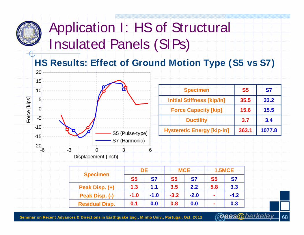
Application I: HS of Structural Insulated Panels (SIPs)
HS Results: Effect of Ground Motion Type (S5 vs S7)
Nail spacing: 3”
Hybrid Simulation with Pulse-Type GM (S5)
Hybrid Simulation with Long Duration, Harmonic GM (S7)
0 10 20 30-0.8
-0.4
0
0.40.8
Acc
(g)
Los Gatos, Loma Prieta, 1989
0 10 20 30-20
-10
0
10
20
Vel
(in/
sec)
0 10 20 30-5
0
5
Time (sec)
Dis
p (in
/sec
)
PGV = 20.0 in/s
PGA = 0.61 g
PGD = 4.53 in
0 25 50 75 100
-0.5
0
0.5
Vinadel Mar, Chile, 1985
0 25 50 75 100-20
-10
0
10
20
0 25 50 75 100-5
0
5
Time (sec)
PGD = 3.87 in
PGV = 11.9 in/s
PGA = 0.54 g
67
Seminar on Recent Advances & Directions in Earthquake Eng., Minho Univ., Portugal, Oct. 2012
Application I: HS of Structural Insulated Panels (SIPs)
HS Results: Effect of Ground Motion Type (S5 vs S7)
-6 -3 0 3 6-20
-15
-10
-5
0
5
10
15
20
Displacement [inch]
Forc
e [k
ips]
S5 (Pulse-type)S7 (Harmonic)
Specimen S5 S7
Initial Stiffness [kip/in] 35.5 33.2
Force Capacity [kip] 15.6 15.5
Ductility 3.7 3.4
Hysteretic Energy [kip-in] 363.1 1077.8
SpecimenDE MCE 1.5MCE
S5 S7 S5 S7 S5 S7Peak Disp. (+) 1.3 1.1 3.5 2.2 5.8 3.3Peak Disp. (-) -1.0 -1.0 -3.2 -2.0 - -4.2Residual Disp. 0.1 0.0 0.8 0.0 - 0.3
68

Seminar on Recent Advances & Directions in Earthquake Eng., Minho Univ., Portugal, Oct. 2012
Application I: HS of Structural Insulated Panels (SIPs)
HS Results: Effect of Ground Motion Type (S5 vs S7)
-6 -3 0 3 6-20
-15
-10
-5
0
5
10
15
20
Displacement [inch]
Forc
e [k
ips]
S5 (Pulse-type)S7 (Harmonic)
SpecimenDE MCE 1.5MCE
S5 S7 S5 S7 S5 S7Peak Disp. (+) 1.3 1.1 3.5 2.2 5.8 3.3Peak Disp. (-) -1.0 -1.0 -3.2 -2.0 - -4.2Residual Disp. 0.1 0.0 0.8 0.0 - 0.3
Specimen Bottom ver. sliding
Bottom gap opening
Top ver. sliding
Top gap opening
Uplift right
Uplift left
Tube sliding
DE S5 0.26 0.02 0.27 0.03 0.08 0.07 0.18S7 0.23 0.02 0.21 0.02 0.15 0.04 0.02
MCE S5 0.63 0.05 0.64 0.09 0.14 0.12 0.19S7 0.45 0.03 0.43 0.04 0.53 0.09 0.06
69

Seminar on Recent Advances & Directions in Earthquake Eng., Minho Univ., Portugal, Oct. 2012
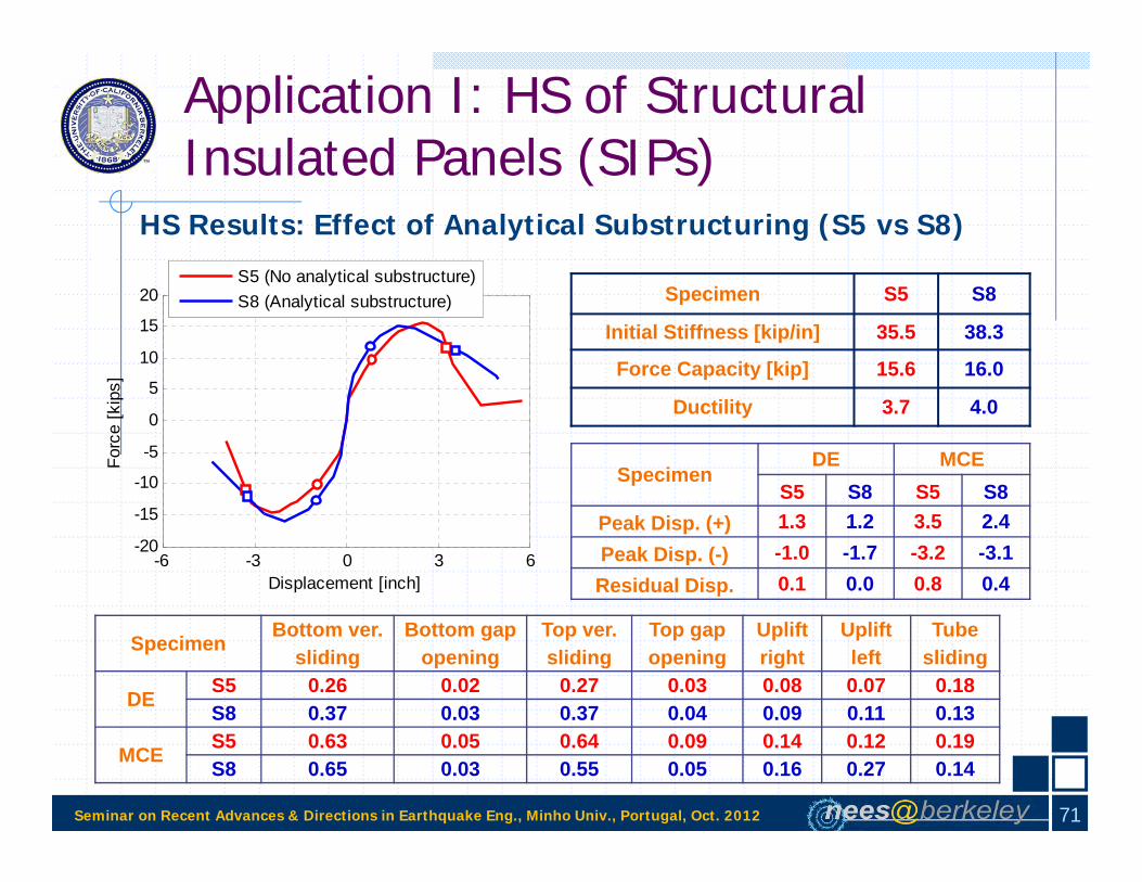
Application I: HS of Structural Insulated Panels (SIPs)
HS Results: Effect of Analytical Substructuring (S5 vs S8)
Pulse-Type GM
Hybrid Simulation with no Analytical Substructure (S5)
Hybrid Simulation with Analytical Substructure (S8)
70
Seminar on Recent Advances & Directions in Earthquake Eng., Minho Univ., Portugal, Oct. 2012
Application I: HS of Structural Insulated Panels (SIPs)
HS Results: Effect of Analytical Substructuring (S5 vs S8)6
-6 -3 0 3 6-20
-15
-10
-5
0
5
10
15
20
Displacement [inch]
Forc
e [k
ips]
S5 (No analytical substructure)S8 (Analytical substructure) Specimen S5 S8
Initial Stiffness [kip/in] 35.5 38.3
Force Capacity [kip] 15.6 16.0
Ductility 3.7 4.0
SpecimenDE MCE
S5 S8 S5 S8Peak Disp. (+) 1.3 1.2 3.5 2.4Peak Disp. (-) -1.0 -1.7 -3.2 -3.1Residual Disp. 0.1 0.0 0.8 0.4
Specimen Bottom ver. sliding
Bottom gap opening
Top ver. sliding
Top gap opening
Uplift right
Uplift left
Tube sliding
DE S5 0.26 0.02 0.27 0.03 0.08 0.07 0.18S8 0.37 0.03 0.37 0.04 0.09 0.11 0.13
MCE S5 0.63 0.05 0.64 0.09 0.14 0.12 0.19S8 0.65 0.03 0.55 0.05 0.16 0.27 0.14
71
Seminar on Recent Advances & Directions in Earthquake Eng., Minho Univ., Portugal, Oct. 2012
Application I: HS of Structural Insulated Panels (SIPs)
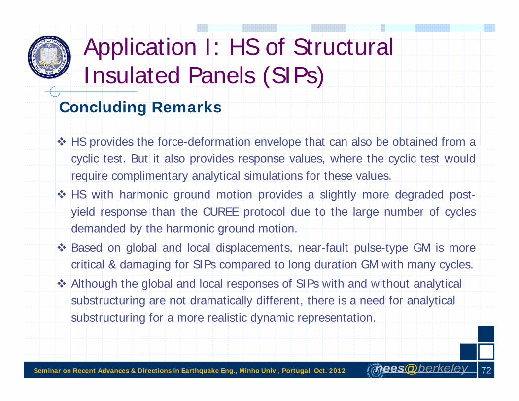
Concluding Remarks
HS provides the force-deformation envelope that can also be obtained from acyclic test. But it also provides response values, where the cyclic test wouldrequire complimentary analytical simulations for these values.
HS with harmonic ground motion provides a slightly more degraded post-yield response than the CUREE protocol due to the large number of cyclesdemanded by the harmonic ground motion.
Based on global and local displacements, near-fault pulse-type GM is morecritical & damaging for SIPs compared to long duration GM with many cycles.
Although the global and local responses of SIPs with and without analytical substructuring are not dramatically different, there is a need for analytical substructuring for a more realistic dynamic representation.
72

Seminar on Recent Advances & Directions in Earthquake Eng., Minho Univ., Portugal, Oct. 2012
Application II: RTHS of Electrical Insulator Posts on a Smart Shaking Table
1. Primary power lines 2. Ground wire 3. Overhead lines 4. Transformer 5. Disconnect switch 6. Circuit breaker 7. Current transformer 8. Lightning arrester 9. Main transformer 10. Control building 11. Security fence 12. Secondary power lines
* Courtesy of Wikipedia
Major elements of an electrical substation (distribution substation shown)
: Primary power lines : Secondary power lines
Disconnect switches are key components of
power transmission and distribution systems.
73

Seminar on Recent Advances & Directions in Earthquake Eng., Minho Univ., Portugal, Oct. 2012
Application II: RTHS of Electrical Insulator Posts on a Smart Shaking Table
1. Disconnect switches: Key components of power transmission & distribution systems to control flow of electricity between substation equipment & to isolate them for maintenance.
2. Seismic qualification tests in typical field installation according to IEEE 693 (Recommended Practices for Seismic Design of Substations) requirements.
Typical field installation of vertical‐break 500‐kV disconnect 3‐phase switch
74

Seminar on Recent Advances & Directions in Earthquake Eng., Minho Univ., Portugal, Oct. 2012
Application II: RTHS of Electrical Insulator Posts on a Smart Shaking Table
Motivation for Hybrid Simulation
EQ damage to 500 kV vertical disconnect switch [E. Fujisaki, PG&E]
Ertaishan Substation (220kV) Destruction, Yingxiu TownWenchuan Earthquake, May 12, 2008 [Q. Xie, Tongji Univ.]
75

Seminar on Recent Advances & Directions in Earthquake Eng., Minho Univ., Portugal, Oct. 2012
Application II: RTHS of Electrical Insulator Posts on a Smart Shaking Table
Motivation for Hybrid Simulation
IEEE693 requires seismic qualification of disconnect switches by shaking table tests A disconnect switch & its support structure should be mounted to a shaking table & tested
76
500 kV switch 230 kV switch

Seminar on Recent Advances & Directions in Earthquake Eng., Minho Univ., Portugal, Oct. 2012
Several tested configurations
Application II: RTHS of Electrical Insulator Posts on a Smart Shaking Table
77

Seminar on Recent Advances & Directions in Earthquake Eng., Minho Univ., Portugal, Oct. 2012
Application II: RTHS of Electrical Insulator Posts on a Smart Shaking Table
500-kV switch testingSupport structure identification tests (stiffness & frequency) with two typical installation:
a) Leveling bolts, no groutb) Leveling bolts with space packed with grout
78

Seminar on Recent Advances & Directions in Earthquake Eng., Minho Univ., Portugal, Oct. 2012
Sub-structuring tests w/o support structure in different configurations
Application II: RTHS of Electrical Insulator Posts on a Smart Shaking Table
79
Seminar on Recent Advances & Directions in Earthquake Eng., Minho Univ., Portugal, Oct. 2012
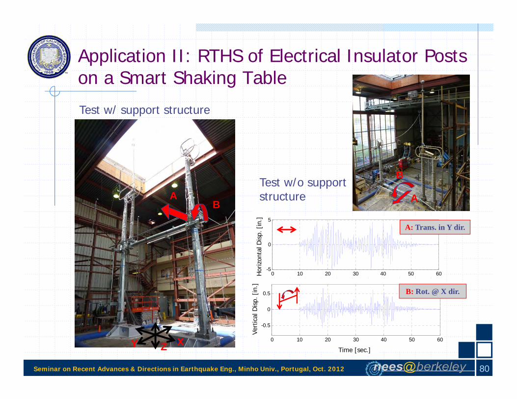
A
B
Test w/ support structure
Test w/o support structure
0 10 20 30 40 50 60
-0.5
0
0.5
Time [sec]
B: Rot. @ X dir.
0 10 20 30 40 50 60-5
0
5A: Trans. in Y dir.
Hor
izon
tal D
isp.
[in
.]Ve
rtic
al D
isp.
[in
.]
Time [sec.]
Application II: RTHS of Electrical Insulator Posts on a Smart Shaking Table
AB
XY Z
80

Seminar on Recent Advances & Directions in Earthquake Eng., Minho Univ., Portugal, Oct. 2012
Application II: RTHS of Electrical Insulator Posts on a Smart Shaking Table
0 10 20 30 40 50 60
-300
-200
-100
0
100
200
300
Time [sec]
Jaw
Insu
lato
r Bot
tom
Stra
in [
stra
in]
Strain at Jaw Insulator Bottom East Side - Open/Open Conf.
w/o supportw/ support
Y-direction Input (Signal A only)
WEST SG#4
A
EAST SG#2
-200 0 200
-300
-200
-100
0
100
200
300
East SG#2 [strain]
Wes
t SG
#4 [s
train
]
Strains at Jaw Insulator Bottom w/o support structure
-200 0 200
-300
-200
-100
0
100
200
300
East SG#2 [strain]
Wes
t SG
#4 [s
train
]
Strains at Jaw Insulator Bottom w/ support structure
81

Seminar on Recent Advances & Directions in Earthquake Eng., Minho Univ., Portugal, Oct. 2012
Application II: RTHS of Electrical Insulator Posts on a Smart Shaking Table
WEST SG#4
A
EAST SG#2
Y-direction + Rotation Input(Signals A + B)
B
0 10 20 30 40 50 60
-300
-200
-100
0
100
200
300
Time [sec]
Jaw
Insu
lato
r Bot
tom
Stra
in [
stra
in]
Strain at Jaw Insulator Bottom East Side - Open/Open Conf.
w/o supportw/ support
-200 0 200
-300
-200
-100
0
100
200
300
East SG#2 [strain]
Wes
t SG
#4 [s
train
]
Strains at Jaw Insulator Bottom w/o support structure
-200 0 200
-300
-200
-100
0
100
200
300
East SG#2 [strain]
Wes
t SG
#4 [s
train
]
Strains at Jaw Insulator Bottom w/ support structure
82

Seminar on Recent Advances & Directions in Earthquake Eng., Minho Univ., Portugal, Oct. 2012
Application II: RTHS of Electrical Insulator Posts on a Smart Shaking Table
Motivation for Hybrid Simulation
Hybrid simulation: a cost effective and efficient alternative to theconventional shaking table testing of the disconnect switches
Requirement for real-time: Rate-dependency of some types of insulatorposts, e.g. polymer composite insulators, mandates use of RTHS
Requirement for a shaking table configuration: Distributed mass of insulatorposts prevents practical use of actuators at discrete locations along theheight & requires RTHS conducted on shaking table configurations.
A RTHS system is developed for testing insulator posts of highvoltage disconnect switches on a “smart” shaking table
83

Seminar on Recent Advances & Directions in Earthquake Eng., Minho Univ., Portugal, Oct. 2012
Application II: RTHS of Electrical Insulator Posts on a Smart Shaking Table
Jaw Post
Braced frame support structure
84

Seminar on Recent Advances & Directions in Earthquake Eng., Minho Univ., Portugal, Oct. 2012
Application II: RTHS of Electrical Insulator Posts on a Smart Shaking Table
3D Support structure
Disconnect switch
Insulator post
2D Support structure
Disconnect switch
Insulator post
For benefits of HS: Support structures computational substructures
& insulator posts physical substructures
85

Seminar on Recent Advances & Directions in Earthquake Eng., Minho Univ., Portugal, Oct. 2012
Application II: RTHS of Electrical Insulator Posts on a Smart Shaking Table
A method of analysis where a structure is split into physical and numericalsubstructures
86

Seminar on Recent Advances & Directions in Earthquake Eng., Minho Univ., Portugal, Oct. 2012
Application II: RTHS of Electrical Insulator Posts on a Smart Shaking Table
Insulator
Calculated support structure response applied to movable platform
Physical Substructure(assumed 1D)
Movable platformFixed tracks
DynamicActuator &Load Cell
Earthquake motion
Computational Substructure
Dynamic DOF
Force feedbackDisplacement command
RTHS: Real TimeHybrid simulation
87

Seminar on Recent Advances & Directions in Earthquake Eng., Minho Univ., Portugal, Oct. 2012
Application II: RTHS of Electrical Insulator Posts on a Smart Shaking Table
Comparison RTHS vs. Shaking Table tests
Full switch shaking table test(PEER, 2008)
RTHS test(UC Berkeley, 2011)
VS.
88

Seminar on Recent Advances & Directions in Earthquake Eng., Minho Univ., Portugal, Oct. 2012
Application II: RTHS of Electrical Insulator Posts on a Smart Shaking Table
Real-time Hybrid Simulation System
mkc
k=F/u
F, u
m, c
m, k, & c: mass, spring, & damping constant for SDOF system representing support frame
gu
89

Seminar on Recent Advances & Directions in Earthquake Eng., Minho Univ., Portugal, Oct. 2012
Application II: RTHS of Electrical Insulator Posts on a Smart Shaking Table
mkc guf
gumfkucvma
Force f includes inertia & damping forces acting on the insulator since HS is conducted in real time
Real-time Hybrid Simulation System
90

Seminar on Recent Advances & Directions in Earthquake Eng., Minho Univ., Portugal, Oct. 2012
Application II: RTHS of Electrical Insulator Posts on a Smart Shaking Table
Real-time Hybrid Simulation System
Uniaxial shaking table
Insulator
Controller
DAQ & Computational platform (DSP)
91

Seminar on Recent Advances & Directions in Earthquake Eng., Minho Univ., Portugal, Oct. 2012
Application II: RTHS of Electrical Insulator Posts on a Smart Shaking Table
Real-time Hybrid Simulation SystemComputational Algorithm: Explicit Newmark Integration
1 Step toGo 8)
1iiSet 7)
uγΔtuu 6)
mmpu 5)
ucfukump 4)
f Measure & u Apply 3)
u2ΔtuΔtuu 2)
uγ1Δtuu 1)
1i c,γΔtmm,u,u,u Initialize
iii
tableeffeffi
iiigeff
ii
1-i2
1-i1-ii
1-i1-ii
eff000
~
~
~
One simulation step completed in one milisecond!
92

Seminar on Recent Advances & Directions in Earthquake Eng., Minho Univ., Portugal, Oct. 2012
Application II: RTHS of Electrical Insulator Posts on a Smart Shaking Table
Real-time Hybrid Simulation SystemImplementation of Computational Algorithm
Digital signal processor (DSP) I/O module of Pacific Instruments (PI) DAQ system
93

Seminar on Recent Advances & Directions in Earthquake Eng., Minho Univ., Portugal, Oct. 2012
Application II: RTHS of Electrical Insulator Posts on a Smart Shaking Table
Real-time Hybrid Simulation SystemFeed-forward error compensation
10 10.2 10.4 10.6 10.8 11-1.2
-1
-0.8
-0.6
-0.4
-0.2
0
0.2
0.4
0.6
0.8
1
1.2
Time(sec)
Dis
plac
emen
t(inc
h)
CommandFeedback
94
-40 -30 -20 -10 0 10 20 30 40-1
-0.8
-0.6
-0.4
-0.2
0
0.2
0.4
0.6
0.8
1
Velocity (v) [inch/sec]
Err
or (e
) [in
ch]
e = 0.042v+0.513
e = 0.0174v
e=0.042v-0.513
Add the error to the command
PIDF

Seminar on Recent Advances & Directions in Earthquake Eng., Minho Univ., Portugal, Oct. 2012
Application II: RTHS of Electrical Insulator Posts on a Smart Shaking Table
Real-time Hybrid Simulation SystemFeed-forward error compensation
10 10.2 10.4 10.6 10.8 11-1.2
-1
-0.8
-0.6
-0.4
-0.2
0
0.2
0.4
0.6
0.8
1
1.2
Time(sec)
Dis
plac
emen
t(inc
h)
CommandFeedback
No correction Feed-forward error correction
10 10.2 10.4 10.6 10.8 11
-1
-0.8
-0.6
-0.4
-0.2
0
0.2
0.4
0.6
0.8
1
Time(sec)
Dis
plac
emen
t(inc
h)
Command Feedback
95

Seminar on Recent Advances & Directions in Earthquake Eng., Minho Univ., Portugal, Oct. 2012
Application II: RTHS of Electrical Insulator Posts on a Smart Shaking Table
Real-time Hybrid Simulation Framework
Verification of algorithm implementation and measurements
Test #
Analytical SubstructureExcitation
ScaleStiffness, k, [kip/in]
Mass, m, slug
Period, T=2π(m/k)0.5,
secDamping ratio
1 4.4 150 0.37 1% 15%
2 4.4 150 0.37 1% 20%
3 4.4 150 0.37 1% 25%

Seminar on Recent Advances & Directions in Earthquake Eng., Minho Univ., Portugal, Oct. 2012
Application II: RTHS of Electrical Insulator Posts on a Smart Shaking Table
Real-time Hybrid Simulation SystemVerification of algorithm implementation and measurements
mkc
F
d
Scale Disp.10% 1 in.20% 2 in.…
-2
0
2
25% scale
-2
0
2
Dis
plac
emen
t [in
ch]
20% scale *25/20
0 10 20 30 40 50 60
-2
0
2
Time [sec]
15% scale *25/15
97

Seminar on Recent Advances & Directions in Earthquake Eng., Minho Univ., Portugal, Oct. 2012
Application II: RTHS of Electrical Insulator Posts on a Smart Shaking Table
Comparison RTHS vs. Shaking Table tests
-200 0 200
-300
-200
-100
0
100
200
300
SG#3 [strain]S
G#4
[ st
rain
]
HS test
-200 0 200
-300
-200
-100
0
100
200
300
SG#16 [strain]
SG
#17
[ st
rain
]
PEER test
SG#3
SG#4
Accelerations at topStrains at bottom
0 10 20 30 40 50 60
-5
0
5
Time [sec]
Acc
eler
atio
n [g
]
PEER test
0 10 20 30 40 50 60
-5
0
5
Time [sec]
Acc
eler
atio
n [g
]
HS Test
Acceleration measured at insulator top
Strains measured at insulator bottom
98

Seminar on Recent Advances & Directions in Earthquake Eng., Minho Univ., Portugal, Oct. 2012
Application II: RTHS of Electrical Insulator Posts on a Smart Shaking Table
Comparison RTHS vs. Shaking Table tests
0 10 20 30 40 50 60-6
-4
-2
0
2
4
6
Time [sec]
Dis
p. [i
nch]
HS Test
0 10 20 30 40 50 60-6
-4
-2
0
2
4
6
Time [sec]
Dis
p. [i
nch]
PEER Test
9 10 11 12 13 14 15 16 17 18 19 20-6
-4
-2
0
2
4
6
Time [sec]
Dis
p. [i
nch]
HS TestPEER Test
0 10 20 30 40 50 60
-2
0
2
Time [sec]
Rel
. Dis
p. [i
nch]
HS Test
0 10 20 30 40 50 60
-2
0
2
Time [sec]
Rel
. Dis
p. [i
nch]
PEER Test
Total and RelativeDisplacements at top
Relative Displacements Total Displacements
99

Seminar on Recent Advances & Directions in Earthquake Eng., Minho Univ., Portugal, Oct. 2012
Application II: RTHS of Electrical Insulator Posts on a Smart Shaking Table
Real-time Hybrid Simulation SystemComparison with conventional shaking table tests
Accelerations at Insulator Top
0 10 20 30 40 50-6
-4
-20
2
4
6
Time [sec]
Acc
eler
atio
n [g
]
-6
-4
-20
2
4
6
Acc
eler
atio
n [g
]
0 10 20 30 40 50-6
-4
-20
2
4
6
Time [sec]
-6
-4
-20
2
4
6
Top of support structure: Real-time HS
Top of support structure: Conventional shaking table
Top of insulator: Real-time HS
Top of insulator: Conventional shaking table
100
$$$
$

Seminar on Recent Advances & Directions in Earthquake Eng., Minho Univ., Portugal, Oct. 2012
Application II: RTHS of Electrical Insulator Posts on a Smart Shaking Table
Real-time Hybrid Simulation SystemComparison with conventional shaking table tests
Strains at Insulator Bottom
0 10 20 30 40 50-400
-200
0
200
400
Time [sec]
Stra
in [
stra
in]
-400
-200
0
200
400
Stra
in [
stra
in]
0 10 20 30 40 50
Time [sec]
West: Real-time HS East: Real-time HS
West: Conventional shaking table East: Conventional shaking table
101
$$$
$

Seminar on Recent Advances & Directions in Earthquake Eng., Minho Univ., Portugal, Oct. 2012
Application II: RTHS of Electrical Insulator Posts on a Smart Shaking Table
Real-time Hybrid Simulation SystemComparison with conventional shaking table tests
0 5 10 15 20 25 30 35 40 45 50-3
-2
-1
0
1
2
3
Dis
plac
emen
t [in
ch]
Time [sec]
-3
-2
-1
0
1
2
3Real-time hybrid simulation
Conventional shaking table
Relative displacement of insulator top w.r.t. top of support structure
102
$$$
$

Seminar on Recent Advances & Directions in Earthquake Eng., Minho Univ., Portugal, Oct. 2012
Application II: RTHS of Electrical Insulator Posts on a Smart Shaking Table
Parametric Study
Polymer Porcelain
103
Seminar on Recent Advances & Directions in Earthquake Eng., Minho Univ., Portugal, Oct. 2012
Application II: RTHS of Electrical Insulator Posts on a Smart Shaking Table
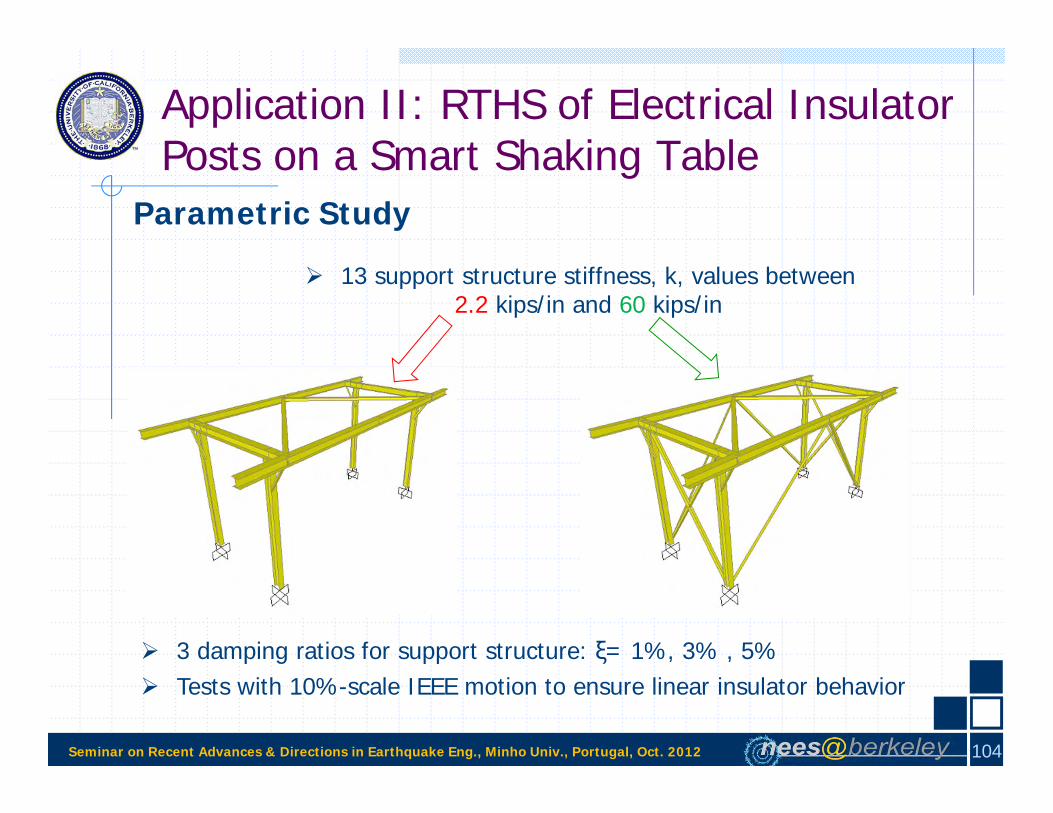
Parametric Study
3 damping ratios for support structure: ξ= 1%, 3% , 5% Tests with 10%-scale IEEE motion to ensure linear insulator behavior
13 support structure stiffness, k, values between2.2 kips/in and 60 kips/in
104

Seminar on Recent Advances & Directions in Earthquake Eng., Minho Univ., Portugal, Oct. 2012
Application II: RTHS of Electrical Insulator Posts on a Smart Shaking Table
Parametric Study: Natural Frequenciesk [kip/in] 60.0 55.0 50.0 44.0 40.0 35.0 30.0 22.0 16.0 11.0 7.0 4.4 2.2 fss [Hz] 10.0 9.6 9.2 8.6 8.2 7.7 7.1 6.1 5.2 4.3 3.4 2.7 1.9 fss / fins (polymer) 1.6 1.6 1.5 1.4 1.3 1.2 1.1 1.0 0.8 0.7 0.6 0.4 0.3 fss / fins (porcelain) 2.0 1.9 1.8 1.7 1.6 1.5 1.4 1.2 1.0 0.8 0.7 0.5 0.4
mk21fss / m = 150 slug
0 2 4 6 8 100
2
4
6
8
10
12
14
16
Frequency [Hz]
Spe
ctra
l Acc
eler
atio
n S
A [g
]
Polymerf = 6.20 Hz
0 0 2 4 6 8 100
5
10
15
20
25
Frequency [Hz]
Porcelainf = 5.13 Hz
105

Seminar on Recent Advances & Directions in Earthquake Eng., Minho Univ., Portugal, Oct. 2012
Application II: RTHS of Electrical Insulator Posts on a Smart Shaking Table
Parametric Study: Effect of Insulator Type
0 1 2 3 4 5 6 7 8 9 10 110
0.02
0.04
0.06
0.08
0.1
Pea
k st
rain
/ Fa
ilure
stra
in (D
CR
)
PolymerPorcelainFailure strains from
fragility tests:Polymer 4800 μstrainPorcelain 1130 μstrain
0 1 2 3 4 5 6 7 8 9 10 11Support structure uncoupled frequency fss [Hz]
0 1 2 3 4 5 6 7 8 9 10 11
106

Seminar on Recent Advances & Directions in Earthquake Eng., Minho Univ., Portugal, Oct. 2012
Application II: RTHS of Electrical Insulator Posts on a Smart Shaking Table
Strains: Porcelain Insulator
0 1 2 3 4 5 6 7 8 9 10 110
10
20
30
40
50
60
70
80
Support structure uncoupled frequency fss [Hz]
Pea
k st
rain
[ st
rain
]0 0.2 0.4 0.6 0.8 1 1.2 1.4 1.6 1.8 2
0
10
20
30
40
50
60
70
80
Ratio of uncoupled frequencies fss / fins
0 1 2 3 4 5 6 7 8 9 10 110
0.01
0.02
0.03
0.04
0.05
0.06
0.07
Pea
k st
rain
/ Fa
ilure
stra
in
1% Damping3% Damping5% Damping
107
Parametric Study: Effect of Support Structure

Seminar on Recent Advances & Directions in Earthquake Eng., Minho Univ., Portugal, Oct. 2012
Application II: RTHS of Electrical Insulator Posts on a Smart Shaking Table
Displacements: Porcelain Insulator
0 1 2 3 4 5 6 7 8 9 10 110
0.25
0.5
0.75
1
1.25
1.5
1.75
2
Analytical substructure uncoupled frequency fss
Dis
plac
emen
t [in
.]
0 0.2 0.4 0.6 0.8 1 1.2 1.4 1.6 1.8 2
0
0.25
0.5
0.75
1
1.25
1.5
1.75
2
Ratio of uncoupled frequencies fss / fins
1% damping3% damping5% damping
Relative displacement ofinsulator w.r.t. ground
108
Parametric Study: Effect of Support Structure

Seminar on Recent Advances & Directions in Earthquake Eng., Minho Univ., Portugal, Oct. 2012
Application II: RTHS of Electrical Insulator Posts on a Smart Shaking Table
Strains: Polymer Insulator
0 1 2 3 4 5 6 7 8 9 10 110
50
100
150
200
250
300
350
400
450
Analytical substructure uncoupled frequency fss [Hz]
Pea
k st
rain
[ st
rain
]0 0.2 0.4 0.6 0.8 1 1.2 1.4 1.6
0
50
100
150
200
250
300
350
400
450
Ratio of uncoupled frequencies fss / fins
0 1 2 3 4 5 6 7 8 9 10 110
0.01
0.02
0.03
0.04
0.05
0.06
0.07
0.08
0.09
Pea
k st
rain
/ Fa
ilure
stra
in
1% Damping5% Damping
109
Parametric Study: Effect of Support Structure

Seminar on Recent Advances & Directions in Earthquake Eng., Minho Univ., Portugal, Oct. 2012
Application II: RTHS of Electrical Insulator Posts on a Smart Shaking Table
Displacements: Polymer Insulator
0 1 2 3 4 5 6 7 8 9 10 110
0.25
0.5
0.75
1
1.25
1.5
Analytical substructure uncoupled frequency fss
Insu
lato
r top
wrt
grou
nd [i
n.]
0 0.2 0.4 0.6 0.8 1 1.2 1.4 1.6
0
0.25
0.5
0.75
1
1.25
1.5
Ratio of uncoupled frequencies fss / fins
1% damping3% damping5% damping
Relative displacement ofinsulator w.r.t. ground
110
Parametric Study: Effect of Support Structure

Seminar on Recent Advances & Directions in Earthquake Eng., Minho Univ., Portugal, Oct. 2012
Application II: RTHS of Electrical Insulator Posts on a Smart Shaking Table
Concluding Remarks
Good match of the results with a benchmark shaking table test is a strongverification of HS
Economically and time efficiently conducted 78 RTHS tests and resultsregarding the design of disconnect switches related to the selection of boththe insulators and support structures are a proof of the usefulness of HS
111

Seminar on Recent Advances & Directions in Earthquake Eng., Minho Univ., Portugal, Oct. 2012
Future Directions
Direct consideration of transfer system and analytical-experimentalboundary in the HS solution
0,H :Control PID
G :ConditionsBoundary :PDEGoverning
dt
tt
u,u u,F
0)u (u,FFuu,RuM
c
ca
HS of analytical substructures with large #of DOF:
Solution affected more from the errors as# of DOF increases
Need to reduce the computation duration(parallel computing)
[OpenSees-SP, OpenSees-MP]
112
Set of Differential-Algebraic Equations (DAE)
450 DOF
0 1000 2000 3000 4000 5000 6000 70000
5
10
15
20
25
30
35
40
# of DOF
Com
puta
tion
Tim
e pe
r Tim
e St
ep [m
s]
MATLABOld OpenSeesNew OpenSeesFORTRAN
applied control

Seminar on Recent Advances & Directions in Earthquake Eng., Minho Univ., Portugal, Oct. 2012
Future DirectionsOptimize design of support structure to improve the switch seismic response
0 0.5 1 1.5 2 2.5 3 3.5 4 4.5
-1
0
1
Time [sec]
Acc
eler
aatio
n [g
]
0 0.5 1 1.5 2 2.5 3 3.5 4 4.5
-1
0
1
Time [sec]
Acc
eler
aatio
n [g
]
Accelerations at Switch Base (Ground Motion)
Accelerations at Insulator Top
?Computational or
experimental
113

Seminar on Recent Advances & Directions in Earthquake Eng., Minho Univ., Portugal, Oct. 2012
Future Directions
114
Need for a mixed control as a combination of acceleration control forhigher frequencies and displacement control for lower frequencies inRTHS on smart shaking table configurations
0 5 10 15 20 25 30 35 40 45
-2
-1
0
1
2
Time (sec)
Dis
plac
emen
t (in
ches
)
Cmdfbk
0 0.5 1 1.5 2 2.5 30
1
2
3
4
period (sec)
Sa
(g)
TargetMeasured
Target
Measured
Command
Feedback

Seminar on Recent Advances & Directions in Earthquake Eng., Minho Univ., Portugal, Oct. 2012
Future Directions
115
Need for a mixed control as a combination of acceleration control forhigher frequencies and displacement control for lower frequencies inRTHS on smart shaking table configurations

Seminar on Recent Advances & Directions in Earthquake Eng., Minho Univ., Portugal, Oct. 2012
Future Directions
116
Need for a mixed control as a combination of acceleration control forhigher frequencies and displacement control for lower frequencies inRTHS on smart shaking table configurations

Seminar on Recent Advances & Directions in Earthquake Eng., Minho Univ., Portugal, Oct. 2012
Thank You!
Questions? Comments?117


![arXiv:1411.4980v1 [q-bio.NC] 18 Nov 2014Keywords: Hybrid stochastic-deterministic simulations, hybrid spatial nonspatial simulations, multiscale simulation, rule-based models, com-](https://img.dokumen.tips/doc/110x75/60fb398067de066b2a7ebf18/arxiv14114980v1-q-bionc-18-nov-2014-keywords-hybrid-stochastic-deterministic.jpg)


![Hybrid Monte-Carlo simulations of electronic properties of graphene [ ArXiv:1206.0619]](https://img.dokumen.tips/doc/110x75/56816623550346895dd97a94/hybrid-monte-carlo-simulations-of-electronic-properties-of-graphene-arxiv12060619-56cd59ad91d40.jpg)
