Embed Size (px)
Citation preview
Hybrid propulsion testing using direct-drive electricalmachines for super yacht and inland shippingPaulides, J.J.H.; Djukic, N.; de Roon, J.A.; Encica, L.
Published in:International Journal of Transportation Engineering and Technology
DOI:10.11648/j.ijtet.20160204.12
Published: 01/12/2016
Document VersionPublisher’s PDF, also known as Version of Record (includes final page, issue and volume numbers)
Please check the document version of this publication:
• A submitted manuscript is the author's version of the article upon submission and before peer-review. There can be important differencesbetween the submitted version and the official published version of record. People interested in the research are advised to contact theauthor for the final version of the publication, or visit the DOI to the publisher's website.• The final author version and the galley proof are versions of the publication after peer review.• The final published version features the final layout of the paper including the volume, issue and page numbers.
Link to publication
General rightsCopyright and moral rights for the publications made accessible in the public portal are retained by the authors and/or other copyright ownersand it is a condition of accessing publications that users recognise and abide by the legal requirements associated with these rights.
• Users may download and print one copy of any publication from the public portal for the purpose of private study or research. • You may not further distribute the material or use it for any profit-making activity or commercial gain • You may freely distribute the URL identifying the publication in the public portal ?
Take down policyIf you believe that this document breaches copyright please contact us providing details, and we will remove access to the work immediatelyand investigate your claim.
Download date: 12. Jul. 2018
International Journal of Transportation Engineering and Technology 2016; 2(4): 42-48
http://www.sciencepublishinggroup.com j/ijtet
doi: 10.11648/j.ijtet.20160204.12
Hybrid Propulsion Testing using Direct-Drive Electrical Machines for Super Yacht and Inland Shipping
Johannes J. H. Paulides1, 2
, Nenad Djukic1, 2
, Johannes A. de Roon1, Laurentiu Encica
1
1Advanced Electromagnetics BV, Sprang-Capelle, The Netherlands
2Electromechanics and Power Electronics, Eindhoven University of Technology, Eindhoven, The Netherlands
Email address: [email protected] (J. J. H. Paulides), [email protected] (J. J. H. Paulides)
To cite this article: Johannes J. H. Paulides, Nenad Djukic, Johannes A. de Roon, Laurentiu Encica. Hybrid Propulsion Testing using Direct-Drive Electrical
Machines for Super Yacht and Inland Shipping. International Journal of Transportation Engineering and Technology.
Vol. 2, No. 4, 2016, pp. 42-48. doi: 10.11648/j.ijtet.20160204.12
Received: August 31, 2016; Accepted: October 31, 2016; Published: November 25, 2016
Abstract: Hybrid or full electric propulsions for inland ships are becoming more popular. In these application, direct-drive
PM propulsion motors are a preferred machine configuration. This paper discusses the challenges to determine the losses, as
estimated with simulations, during the testing procedures of a 350kW at 300rpm, respectively. The full-load testing of the drive
system is performed by mechanically coupling two identical machines, of which one operates as a motor and the other as a
generator, or “back-to-back” testing configuration. Two Direct-Drive PM machines have been manufactured to validate key
findings from the modelling, particularly in terms of loss predictions, thermal modelling and influence of the design features
such as magnet segmentation. A back-to-back set-up is created for testing these machines with a speed range of 0-450 rpm.
Before the measurement commended, tests were carried out in accordance with IEC60034-1, IEC60034-15, IEC60085-1,
IEEE43, IEEE118 and Lloyd's register. These tests included: surge, resistance, winding symmetry, high voltage test, insulation
resistance and polarization index. All these tests were successfully completed and agreed with the analysis as described before.
Following the motors have been installed in an inland ship hybrid propulsion.
Keywords: Hybrid Propulsion, High Torque Machines, Electric Vessel, Hybrid Ship, Super Yacht, Hybrid Yacht,
Brushless Machine, Electric Propulsion, Electrical Machines, Testing, Direct-Drive Motor
1. Introduction
DIESEL-ELECTRIC propulsion is very effective in ships that
are operated in partial load conditions for a significant
portion of their time, e.g. inland ships that require up-, down-
stream, harbor and canal operation. The main advantages of
the diesel-electric propulsion are: flexibility (better space
utilization and redundancy), more economical operation, less
maintenance and reduced environmental pollution. In these
hybrid ships, the popularity of diesel-electric propulsion
systems (0.5–3.0 MW range) is ever increasing, since
potentially 10-25% diesel fuel can be saved on specific
journeys [1, 2]. Of course, also in shipping applications
operating costs should be minimized, hence it is no surprise
that fleet owners are considering high-efficient machines that
can directly drive their propeller for their diesel-electric
propulsion [3, 4]. Of course, there are different hybrid
topologies requiring sizing criteria of components and related
control strategies, finalized to maximize different objective
functions: weight and space reduction on-board, fuel
economy, pollution reduction or optimized efficiencies [5].
This paper concerns the testing of electrical machines for a
hybrid propulsion for an inland ship application. Some
authors have also described such high torque PM motors
which are special to this system, including the use of 16-
phase windings for lower harmonic content, larger damper
winding arrangements and high strength rotor magnet
containment [6]. While others have reviewed DC hybrid
systems by modeling and simulation [7]. Further, the high
level of complexity of hybrid systems is also giving rise to
modern sophisticated ship electrical power management and
control systems resembling the ones adopted in land-based
hybrid systems [8]. Beside in-land ship applications, hybrid
propulsion is also considered for luxury yacht applications
[9]. Modeling is an important aspect of these hybrid systems
as also discussed in [10]. In general modeling of electrical
machines is an important aspect to advance electrical
International Journal of Transportation Engineering and Technology 2016; 2(4): 42-48 43
machines [11-15]. This is also the subject of this paper,
where these models are aided by tests that are challenging in
nature.
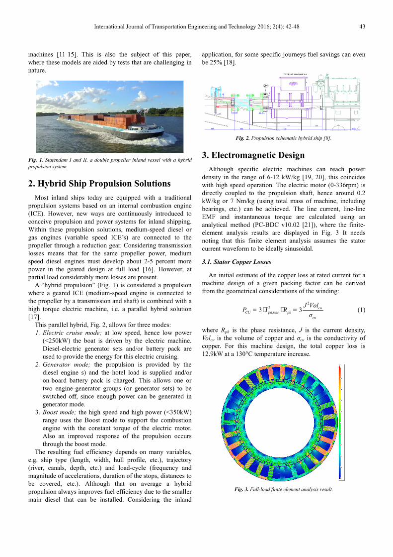
Fig. 1. Statendam I and II, a double propeller inland vessel with a hybrid
propulsion system.
2. Hybrid Ship Propulsion Solutions
Most inland ships today are equipped with a traditional
propulsion systems based on an internal combustion engine
(ICE). However, new ways are continuously introduced to
conceive propulsion and power systems for inland shipping.
Within these propulsion solutions, medium-speed diesel or
gas engines (variable speed ICE’s) are connected to the
propeller through a reduction gear. Considering transmission
losses means that for the same propeller power, medium
speed diesel engines must develop about 2-5 percent more
power in the geared design at full load [16]. However, at
partial load considerably more losses are present.
A “hybrid propulsion” (Fig. 1) is considered a propulsion
where a geared ICE (medium-speed engine is connected to
the propeller by a transmission and shaft) is combined with a
high torque electric machine, i.e. a parallel hybrid solution
[17].
This parallel hybrid, Fig. 2, allows for three modes:
1. Electric cruise mode; at low speed, hence low power
(<250kW) the boat is driven by the electric machine.
Diesel-electric generator sets and/or battery pack are
used to provide the energy for this electric cruising.
2. Generator mode; the propulsion is provided by the
diesel engine s) and the hotel load is supplied and/or
on-board battery pack is charged. This allows one or
two engine-generator groups (or generator sets) to be
switched off, since enough power can be generated in
generator mode.
3. Boost mode; the high speed and high power (<350kW)
range uses the Boost mode to support the combustion
engine with the constant torque of the electric motor.
Also an improved response of the propulsion occurs
through the boost mode.
The resulting fuel efficiency depends on many variables,
e.g. ship type (length, width, hull profile, etc.), trajectory
(river, canals, depth, etc.) and load-cycle (frequency and
magnitude of accelerations, duration of the stops, distances to
be covered, etc.). Although that on average a hybrid
propulsion always improves fuel efficiency due to the smaller
main diesel that can be installed. Considering the inland
application, for some specific journeys fuel savings can even
be 25% [18].
Fig. 2. Propulsion schematic hybrid ship [8].
3. Electromagnetic Design
Although specific electric machines can reach power
density in the range of 6-12 kW/kg [19, 20], this coincides
with high speed operation. The electric motor (0-336rpm) is
directly coupled to the propulsion shaft, hence around 0.2
kW/kg or 7 Nm/kg (using total mass of machine, including
bearings, etc.) can be achieved. The line current, line-line
EMF and instantaneous torque are calculated using an
analytical method (PC-BDC v10.02 [21]), where the finite-
element analysis results are displayed in Fig. 3 It needs
noting that this finite element analysis assumes the stator
current waveform to be ideally sinusoidal.
3.1. Stator Copper Losses
An initial estimate of the copper loss at rated current for a
machine design of a given packing factor can be derived
from the geometrical considerations of the winding:
2
23 3 cu
CU ph,rms ph
cu
J VolP = I R =
σ⋅ ⋅ (1)
where Rph is the phase resistance, J is the current density,
Volcu is the volume of copper and σcu is the conductivity of
copper. For this machine design, the total copper loss is
12.9kW at a 130°C temperature increase.
Fig. 3. Full-load finite element analysis result.

44 Johannes J. H. Paulides et al.: Hybrid Propulsion Testing using Direct-Drive Electrical Machines for Super
Yacht and Inland Shipping
3.2. Stator Iron Losses
The low-speed nature of this application is likely to mean
that stator iron loss will constitute a small proportion of the
total loss. Here, the iron losses are obtained using finite-
element computations. This calculation assumes sinusoidal
currents, i.e. no switching frequency effect, and therefore the
total losses are expected to be somewhat higher than
estimated (~1.5-2 times). This gives that for a standard grade
of 0.5mm lamination around 2.5kW iron loss is estimated.
3.3. Magnet Losses
A critical design issue in water cooled PM machines is
magnet loss. A number of design features are often
incorporated into permanent magnet rotors to reduce the rotor
magnet losses: rotor magnet segmentation, electrically
conducting rotor screens and alternative winding
configurations and phase numbers [22-24]. Here, the full-
load loss has been analyzed using transient finite element
analysis coupled to an electrical circuit. The electrical circuit
consists of a three-phase inverter. The eddy-current skin
depth within the magnets is 70.9mm, which is much larger
than the magnet thickness (14mm), meaning the eddy-current
are resistance limited and have been estimated via analytical
methods to be ~600W at 300rpm, respectively.
4. Thermal Design
Accurate thermal modelling is critical to ensure that a design
is viable in terms of the maximum temperature constraints. A
lumped parameter equivalent thermal network approach was
adopted using Motor-CAD [25], as shown in Fig. 4. This model
employs an equivalent thermal network consisting of power
sources, thermal resistances and thermal capacitances. In this
model a total copper loss of 480W is generated in the region of
the coil shown (this value corresponding to a rated load overall
copper loss of ~13kW for the entire machine, which consist of
27 such half coil regions).
Fig. 4. Used lumped parameter model illustrating the various temperatures within the machine.
5. Motor Manufacturing & Testing
Two PM machines have been manufactured to
experimentally validate the design procedure employed.
The objectives of this experimental phase are to validate
key findings from the modelling, particularly in terms of
loss predictions, thermal modelling and influence of the
design features such as magnet segmentation. A back-to-
back set-up is created for testing this machine with a
continuous power rating of 0-350kW, with a speed range
of 0-400 rpm. Before the measurement commended, tests
were carried out in accordance with IEC60034-1,
IEC60034-15, IEC60085-1, IEEE43, IEEE118 and Lloyd's
register. These tests included: resistance measurement,
winding symmetry, high voltage test, insulation resistance,
polarization index and surge test. All these tests were
successfully completed and agreed with the analysis as
described before.
International Journal of Transportation Engineering and Technology 2016; 2(4): 42-48 45
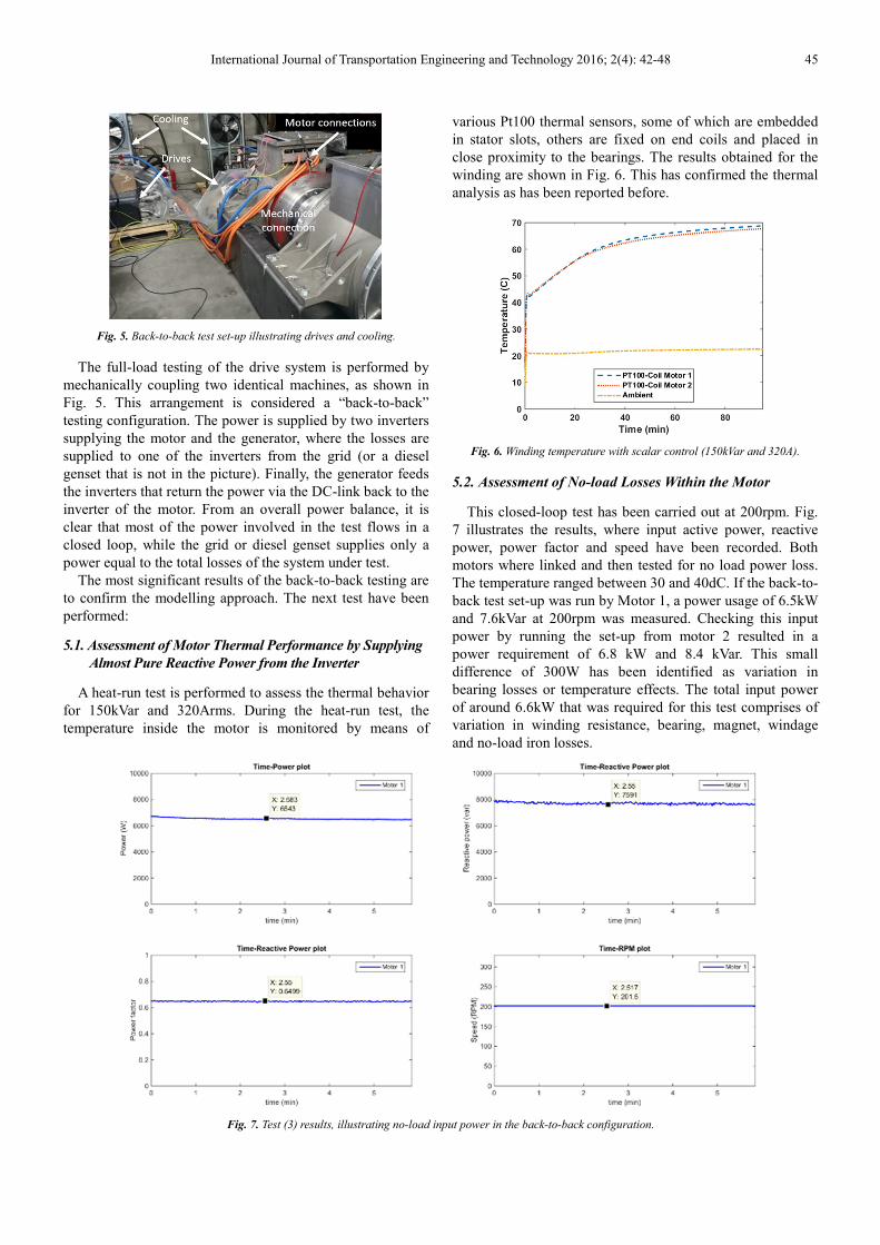
Fig. 5. Back-to-back test set-up illustrating drives and cooling.
The full-load testing of the drive system is performed by
mechanically coupling two identical machines, as shown in
Fig. 5. This arrangement is considered a “back-to-back”
testing configuration. The power is supplied by two inverters
supplying the motor and the generator, where the losses are
supplied to one of the inverters from the grid (or a diesel
genset that is not in the picture). Finally, the generator feeds
the inverters that return the power via the DC-link back to the
inverter of the motor. From an overall power balance, it is
clear that most of the power involved in the test flows in a
closed loop, while the grid or diesel genset supplies only a
power equal to the total losses of the system under test.
The most significant results of the back-to-back testing are
to confirm the modelling approach. The next test have been
performed:
5.1. Assessment of Motor Thermal Performance by Supplying
Almost Pure Reactive Power from the Inverter
A heat-run test is performed to assess the thermal behavior
for 150kVar and 320Arms. During the heat-run test, the
temperature inside the motor is monitored by means of
various Pt100 thermal sensors, some of which are embedded
in stator slots, others are fixed on end coils and placed in
close proximity to the bearings. The results obtained for the
winding are shown in Fig. 6. This has confirmed the thermal
analysis as has been reported before.
Fig. 6. Winding temperature with scalar control (150kVar and 320A).
5.2. Assessment of No-load Losses Within the Motor
This closed-loop test has been carried out at 200rpm. Fig.
7 illustrates the results, where input active power, reactive
power, power factor and speed have been recorded. Both
motors where linked and then tested for no load power loss.
The temperature ranged between 30 and 40dC. If the back-to-
back test set-up was run by Motor 1, a power usage of 6.5kW
and 7.6kVar at 200rpm was measured. Checking this input
power by running the set-up from motor 2 resulted in a
power requirement of 6.8 kW and 8.4 kVar. This small
difference of 300W has been identified as variation in
bearing losses or temperature effects. The total input power
of around 6.6kW that was required for this test comprises of
variation in winding resistance, bearing, magnet, windage
and no-load iron losses.
Fig. 7. Test (3) results, illustrating no-load input power in the back-to-back configuration.
46 Johannes J. H. Paulides et al.: Hybrid Propulsion Testing using Direct-Drive Electrical Machines for Super
Yacht and Inland Shipping
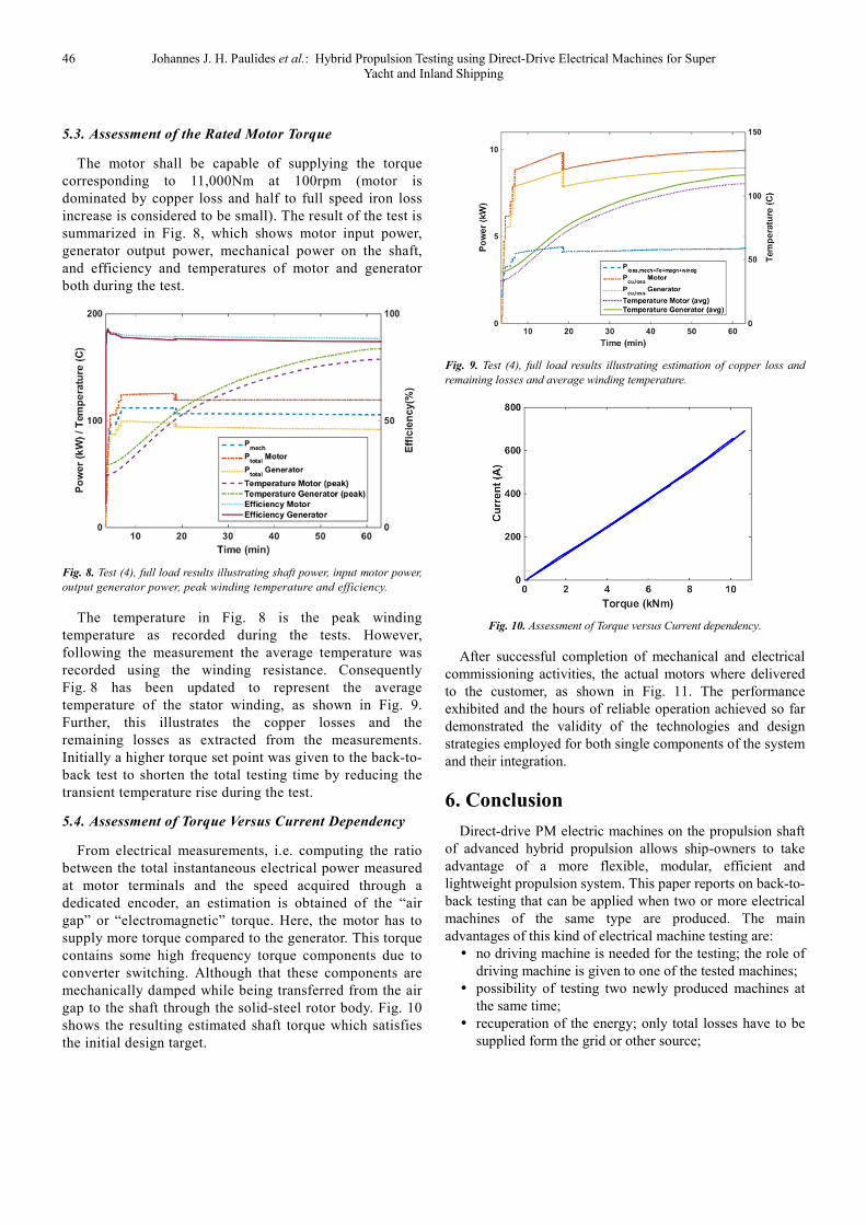
5.3. Assessment of the Rated Motor Torque
The motor shall be capable of supplying the torque
corresponding to 11,000Nm at 100rpm (motor is
dominated by copper loss and half to full speed iron loss
increase is considered to be small). The result of the test is
summarized in Fig. 8, which shows motor input power,
generator output power, mechanical power on the shaft,
and efficiency and temperatures of motor and generator
both during the test.
Fig. 8. Test (4), full load results illustrating shaft power, input motor power,
output generator power, peak winding temperature and efficiency.
The temperature in Fig. 8 is the peak winding
temperature as recorded during the tests. However,
following the measurement the average temperature was
recorded using the winding resistance. Consequently
Fig. 8 has been updated to represent the average
temperature of the stator winding, as shown in Fig. 9.
Further, this illustrates the copper losses and the
remaining losses as extracted from the measurements.
Initially a higher torque set point was given to the back-to-
back test to shorten the total testing time by reducing the
transient temperature rise during the test.
5.4. Assessment of Torque Versus Current Dependency
From electrical measurements, i.e. computing the ratio
between the total instantaneous electrical power measured
at motor terminals and the speed acquired through a
dedicated encoder, an estimation is obtained of the “air
gap” or “electromagnetic” torque. Here, the motor has to
supply more torque compared to the generator. This torque
contains some high frequency torque components due to
converter switching. Although that these components are
mechanically damped while being transferred from the air
gap to the shaft through the solid-steel rotor body. Fig. 10
shows the resulting estimated shaft torque which satisfies
the initial design target.
Fig. 9. Test (4), full load results illustrating estimation of copper loss and
remaining losses and average winding temperature.
Fig. 10. Assessment of Torque versus Current dependency.
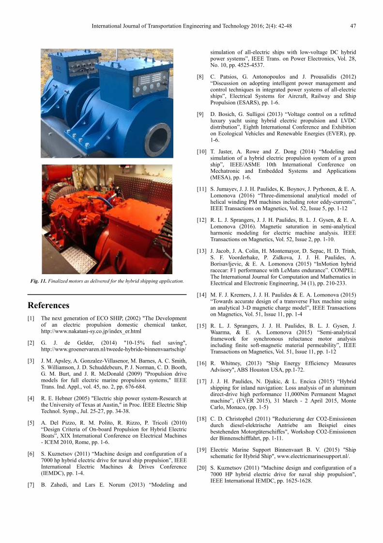
After successful completion of mechanical and electrical
commissioning activities, the actual motors where delivered
to the customer, as shown in Fig. 11. The performance
exhibited and the hours of reliable operation achieved so far
demonstrated the validity of the technologies and design
strategies employed for both single components of the system
and their integration.
6. Conclusion
Direct-drive PM electric machines on the propulsion shaft
of advanced hybrid propulsion allows ship-owners to take
advantage of a more flexible, modular, efficient and
lightweight propulsion system. This paper reports on back-to-
back testing that can be applied when two or more electrical
machines of the same type are produced. The main
advantages of this kind of electrical machine testing are:
� no driving machine is needed for the testing; the role of
driving machine is given to one of the tested machines;
� possibility of testing two newly produced machines at
the same time;
� recuperation of the energy; only total losses have to be
supplied form the grid or other source;
International Journal of Transportation Engineering and Technology 2016; 2(4): 42-48 47
Fig. 11. Finalized motors as delivered for the hybrid shipping application.
References
[1] The next generation of ECO SHIP, (2002) "The Development of an electric propulsion domestic chemical tanker, http://www.nakatani-sy.co.jp/index_er.html
[2] G. J. de Gelder, (2014) "10-15% fuel saving", http://www.groenervaren.nl/tweede-hybride-binnenvaartschip/
[3] J. M. Apsley, A. Gonzalez-Villasenor, M. Barnes, A. C. Smith, S. Williamson, J. D. Schuddebeurs, P. J. Norman, C. D. Booth, G. M. Burt, and J. R. McDonald (2009) "Propulsion drive models for full electric marine propulsion systems," IEEE Trans. Ind. Appl., vol. 45, no. 2, pp. 676-684.
[4] R. E. Hebner (2005) "Electric ship power system-Research at the University of Texas at Austin," in Proc. IEEE Electric Ship Technol. Symp., Jul. 25-27, pp. 34-38.
[5] A. Del Pizzo, R. M. Polito, R. Rizzo, P. Tricoli (2010) “Design Criteria of On-board Propulsion for Hybrid Electric Boats”, XIX International Conference on Electrical Machines - ICEM 2010, Rome, pp. 1-6.
[6] S. Kuznetsov (2011) “Machine design and configuration of a 7000 hp hybrid electric drive for naval ship propulsion”, IEEE International Electric Machines & Drives Conference (IEMDC), pp. 1-4.
[7] B. Zahedi, and Lars E. Norum (2013) “Modeling and
simulation of all-electric ships with low-voltage DC hybrid power systems”, IEEE Trans. on Power Electronics, Vol. 28, No. 10, pp. 4525-4537.
[8] C. Patsios, G. Antonopoulos and J. Prousalidis (2012) “Discussion on adopting intelligent power management and control techniques in integrated power systems of all-electric ships”, Electrical Systems for Aircraft, Railway and Ship Propulsion (ESARS), pp. 1-6.
[9] D. Bosich, G. Sulligoi (2013) “Voltage control on a refitted luxury yacht using hybrid electric propulsion and LVDC distribution”, Eighth International Conference and Exhibition on Ecological Vehicles and Renewable Energies (EVER), pp. 1-6.
[10] T. Jaster, A. Rowe and Z. Dong (2014) “Modeling and simulation of a hybrid electric propulsion system of a green ship”, IEEE/ASME 10th International Conference on Mechatronic and Embedded Systems and Applications (MESA), pp. 1-6.
[11] S. Jumayev, J. J. H. Paulides, K. Boynov, J. Pyrhonen, & E. A. Lomonova (2016) “Three-dimensional analytical model of helical winding PM machines including rotor eddy-currents”, IEEE Transactions on Magnetics, Vol. 52, Issue 5, pp. 1-12
[12] R. L. J. Sprangers, J. J. H. Paulides, B. L. J. Gysen, & E. A. Lomonova (2016). Magnetic saturation in semi-analytical harmonic modeling for electric machine analysis. IEEE Transactions on Magnetics, Vol. 52, Issue 2, pp. 1-10.
[13] J. Jacob, J. A. Colin, H. Montemayor, D. Sepac, H. D. Trinh, S. F. Voorderhake, P. Zidkova, J. J. H. Paulides, A. Borisavljevic, & E. A. Lomonova (2015) “InMotion hybrid racecar: F1 performance with LeMans endurance”. COMPEL: The International Journal for Computation and Mathematics in Electrical and Electronic Engineering, 34 (1), pp. 210-233.
[14] M. F. J. Kremers, J. J. H. Paulides & E. A. Lomonova (2015) “Towards accurate design of a transverse Flux machine using an analytical 3-D magnetic charge model”, IEEE Transactions on Magnetics, Vol. 51, Issue 11, pp. 1-4
[15] R. L. J. Sprangers, J. J. H. Paulides, B. L. J. Gysen, J. Waarma, & E. A. Lomonova (2015) “Semi-analytical framework for synchronous reluctance motor analysis including finite soft-magnetic material permeability”, IEEE Transactions on Magnetics, Vol. 51, Issue 11, pp. 1-12
[16] R. Whitney, (2013) "Ship Energy Efficiency Measures Advisory", ABS Houston USA, pp.1-72.
[17] J. J. H. Paulides, N. Djukic, & L. Encica (2015) “Hybrid shipping for inland navigation: Loss analysis of an aluminum direct-drive high performance 11,000Nm Permanent Magnet machine”, (EVER 2015), 31 March - 2 April 2015, Monte Carlo, Monaco, (pp. 1-5)
[18] C. D. Christophel (2011) "Reduzierung der CO2-Emissionen durch diesel-elektrische Antriebe am Beispiel eines bestehenden Motorgüterschiffes", Workshop CO2-Emissionen der Binnenschifffahrt, pp. 1-11.
[19] Electric Marine Support Binnenvaart B. V. (2015) "Ship schematic for Hybrid Ship", www.electricmarinesupport.nl/.
[20] S. Kuznetsov (2011) "Machine design and configuration of a 7000 HP hybrid electric drive for naval ship propulsion", IEEE International IEMDC, pp. 1625-1628.

48 Johannes J. H. Paulides et al.: Hybrid Propulsion Testing using Direct-Drive Electrical Machines for Super
Yacht and Inland Shipping
[21] J. J. H. Paulides, L. Encica, T. F. Beerneart, H. H. F van der Velden, A. G. P. Parfant and E. A. Lomonova, "Ultra-light-weight high torque density brushless PM machine design: Driving-cycle investigation of a Four-Wheel drive race car", 2015 Tenth International Conference on Ecological Vehicles and Renewable Energies (EVER), pp. 1-7.
[22] "SPEED," available on http://www.cd-adapco.com.
[23] N. Taghizadeh Irenji, S. M. Abu Sharkh, M.R. Harris (2000) "Effect of rotor sleeve conductivity on rotor eddy-current loss in high-speed PM machines", ICEM Espoo Finland, pp. 645-648.
[24] J. L. F. Van der Veen, L. J. J. Offringa, A. J. A. Vandenput (1997) "Minimising rotor losses in high-speed high-power permanent magnet synchronous generators with rectifier load", IEE Proc Electrical Power applications, Vol. 144, No. 5, pp. 331-337.
[25] E. Bunzel, G. Mueller (1991) "General analysis of a 6-phase synchronous machine", Int. conf. Evolution and modern aspects of synchronous machines, pp. 333-340.
[26] "Motor-CAD and Motor-LAB," available on www.motor-design.com.