Embed Size (px)
Citation preview

Hybrid Modelling and Control of the CommonRail Injection System
Andrea Balluchi1,2, Antonio Bicchi2, Emanuele Mazzi1,2,Alberto L. Sangiovanni Vincentelli1,3, and Gabriele Serra4
1 PARADES, Via S. Pantaleo, 66, 00186 Roma, Italy{balluchi, emazzi, alberto}@parades.rm.cnr.it
2 Centro Interdipartimentale di Ricerca “Enrico Piaggio”,Universita di Pisa, 56100 Pisa, Italy
[email protected] Dept. of EECS., University of California at Berkeley, CA 94720, USA
[email protected] Magneti Marelli Powertrain, Via del Timavo 33, 40134 Bologna, Italy
Abstract. We present an industrial case study in automotive controlof significant complexity: the new common rail fuel injection system forDiesel engines, currently under production by Magneti Marelli Power-train. In this system, a flow–rate valve, introduced before the High Pres-sure (HP) pump, regulates the fuel flow that supplies the common railaccording to the engine operating point. The standard approach followedin automotive control is to use a mean–value model for the plant and todevelop a controller based on this model. In this particular case, this ap-proach does not provide a satisfactory solution as the discrete–continuousinteractions in the fuel injection system, due to the slow time–varying fre-quency of the HP pump cycles and the fast sampling frequency of sensingand actuation, play a fundamental role. We present a design approachbased on a hybrid model of the Magneti Marelli Powertrain common–railfuel–injection system for four-cylinder multi–jet engines and a hybrid ap-proach to the design of a rail pressure controller. The hybrid controller iscompared with a classical mean–value based approach to automotive con-trol design whereby the quality of the hybrid solution is demonstrated.
1 Introduction
Common–rail fuel–injection is the dominant system in diesel engine control. Incommon–rail fuel–injection systems (see Figure 1), a low-pressure pump locatedin the tank supplies an HP pump with a fuel flow at the pressure of 4–6 bars.The HP pump delivers the fuel at high pressure (from 150 to 1600 bars) to thecommon rail, which supplies all the injectors. The fuel pressure in the commonrail depends on the balance between the inlet fuel flow from the HP pump andthe outlet fuel flow to the injectors. The common–rail pressure is controlledto achieve tracking of a reference signal that is generated on–line (it dependson the engine operating point) to optimize fuel injection and to obtain propercombustion with low emissions and noise.
J Hespanha and A. Tiwari (Eds.): HSCC 2006, LNCS 3927, pp. 79–92, 2006.c© Springer-Verlag Berlin Heidelberg 2006.

80 A. Balluchi et al.
Fig. 1. Common rail fuel injection system developed by Magneti Marelli Powertrain
In the novel fuel–injection system developed by Magneti Marelli Powertrain,a flow–rate valve located before the HP pump allows for effective control ofthe amount of fuel that is compressed to high pressure and delivered to therail. The HP pump and, hence, the rail are supplied with the precise amountof fuel flow that is necessary for fuel injection, achieving high efficiency of theinjection system. The previous fuel injection system, which was not equippedwith the flow–rate valve, was characterized by a high power consumption by theHP pump, which always supplied with the maximum fuel flow for the currentoperating condition (rail pressure control was achieved by a regulation valvelocated on the rail).
To control the rail pressure efficiently, we need to model accurately the in-teraction between discrete and continuous behaviours of the injection systemcomponents, exhibiting the pulsating evolution of the rail pressure due the dis-continuous inlet fuel flow from the HP pump and outlet fuel flows to the injectors.To do so, we present in this paper a hybrid model of the Magneti Marelli Pow-ertrain common–rail fuel–injection system for four-cylinder multi–jet engines.Motivated by the success in solving other automotive control problems using hy-brid system methodologies, e.g. cut-off control [1], intake throttle valve control[2], actual engaged gear identification [3], and adaptive cruise control [4], we de-veloped a hybrid rail pressure controller that exhibits excellent performance. Tocompare our solution with the standard design methodology adopted in the auto-motive industry based on mean–value models of the plant, we present a classicalSmith Predictor discrete–time controller. Simulations of the closed–loop systemshow that the mean–value model design approach does not achieve the samequality of design as the hybrid approach.

Hybrid Modelling and Control of the Common Rail Injection System 81
We believe this paper underlines the important role played by hybrid systemsin solving complex industrial control problems in a domain as economically rel-evant as the automotive sector.
2 Hybrid Model of the Common Rail Injection System
The proposed hybrid model of the injection system, shown in Figure 2, consistsof: the flow–rate valve, the HP pump, the injectors and the common rail [5]. Theproposed hybrid model describes accurately the interacting discrete and contin-uous behaviours of the injection system components, reproducing the pulsatingevolution of the rail pressure due the discontinuous inlet fuel flow from the HPpump and outlet fuel flows to the injectors. The rail pressure p [bar] is the con-trolled output. The flow–rate valve duty cycle u ∈ [0, 1] is the control input. Theinjectors fuel flow qINJ [mm3/sec] , which depends on the injectors opening timesET [sec], is considered as a disturbance to be compensated. The models of thecomponents of the system are described in the next sections using the hybridautomaton formalism [6].
Fig. 2. Hybrid model of the fuel injection system
2.1 The Flow–Rate Valve
The hybrid model of the flow–rate valve is depicted in Figure 3 and includes:the valve PWM1 electrical driver; the dynamics of the coil current I [A]; andthe relation between the coil current and the fuel flow–rate qM [mm3/sec] acrossthe valve.
The PWM electrical driver model is a hybrid model with as output a squarewave voltage vPWM(t) ∈ {0, Vbat} given by pulse–width modulation of the batteryvoltage Vbat with duty cycle defined by the control input signal u(t) ∈ [0, 1]. Itsimplementation is based on a triangular wave generator with period T0 and
1 Pulse Width Modulation.

82 A. Balluchi et al.
Fig. 3. Flow–rate valve hybrid model
output α(t), modelled as a hybrid system. The dynamics of the coil current Idepends on the coil resistance R and inductance L. The relation between thecoil current I and the fuel flow rate qM is given by a nonlinear function
qM = fM (I) (1)
represented as a piecewise affine expression (see [7]).
2.2 The HP Pump
The HP pump consists of three identical hydraulic rams mounted on the sameshaft with a relative phase of 120o (see Figure 4). Since the pump is powered by
Fig. 4. HP pump hybrid model

Hybrid Modelling and Control of the Common Rail Injection System 83
η(p, n)
n [rpm]
Fig. 5. HP pump efficiency
the camshaft, its revolution speed depends on the engine speed n [rpm]. Pumpefficiency reduces the fuel flow qI [mm3/sec] to the rams, i.e.
qI = η(p, n)qM (2)
where the efficiency η(p, n) depends on the rail pressure and the engine speed asdepicted in Figure 5. The HP pump fuel flow to the rail qP [mm3/sec] is obtainedby adding the contributions qP
i of the three rams: qP = qP1 + qP
2 + qP3 .
The partial closure of the flow–rate regulation valve produces the cavitationphenomenon in the pump, which affects both the intake and compression phases.For small effective area of the flow–rate valve, the pressure reduction in theram during the intake phase causes fuel vaporization [8]. As a consequence, theamount of fuel charge in volume is lower than the geometric displacement of thecylinder. The partial fuel charge depends on the amount of fuel vapor in thecylinder. In a first part of the compression phase, the ram does not deliver anyfuel to the rail. In fact, at the beginning of the compression phase, the increase ofpressure inside the cylinder causes fuel condensation only. The outlet flow to therail starts when the fuel is completely in the liquid state, i.e. when the geometricvolume of the cylinder (which decreases during compression) equals the fuelcharge in volume. From this time on, pressure increase in the ram produces theopening of outlet valve and the exit of the compressed fuel to the rail.
The hybrid model of the i-th ram of the HP pump is depicted in Figure 6. Itsevolution is determined by the ram angle φi [o]. Since the camshaft revolutionspeed is half the engine speed n, then the ram angle dynamics is φi = 360
2n60 =
3n, where n is the engine speed in rpm.The hybrid model contains two macro discrete states corresponding to the
intake and compress phases, which have durations of half camshaft cycle. Thepumping cycle starts with the beginning of the intake phase, which is triggered bythe guard φi = 180o. The camshaft sensor detects the beginning of the pumpingcycle by emitting the output event triggeri at transition time.
Since the intake duration is 180o and the three rams are mounted with arelative phase of 120o, then the intake phases of the rams partially overlap.Intake overlapping results in different supplying fuel flow to the rams. Rams
84 A. Balluchi et al.
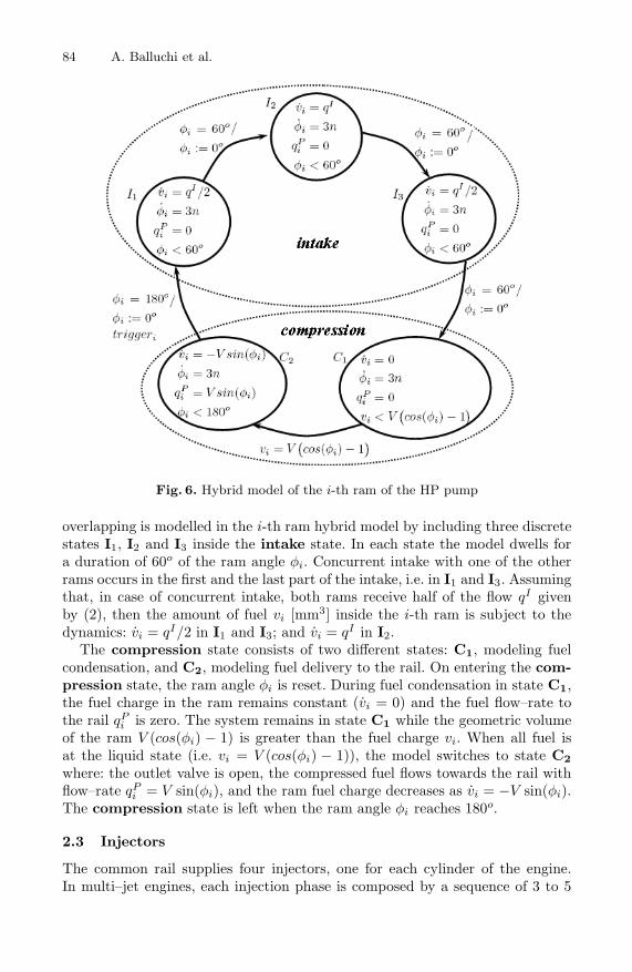
Fig. 6. Hybrid model of the i-th ram of the HP pump
overlapping is modelled in the i-th ram hybrid model by including three discretestates I1, I2 and I3 inside the intake state. In each state the model dwells fora duration of 60o of the ram angle φi. Concurrent intake with one of the otherrams occurs in the first and the last part of the intake, i.e. in I1 and I3. Assumingthat, in case of concurrent intake, both rams receive half of the flow qI givenby (2), then the amount of fuel vi [mm3] inside the i-th ram is subject to thedynamics: vi = qI/2 in I1 and I3; and vi = qI in I2.
The compression state consists of two different states: C1, modeling fuelcondensation, and C2, modeling fuel delivery to the rail. On entering the com-pression state, the ram angle φi is reset. During fuel condensation in state C1,the fuel charge in the ram remains constant (vi = 0) and the fuel flow–rate tothe rail qP
i is zero. The system remains in state C1 while the geometric volumeof the ram V (cos(φi) − 1) is greater than the fuel charge vi. When all fuel isat the liquid state (i.e. vi = V (cos(φi) − 1)), the model switches to state C2
where: the outlet valve is open, the compressed fuel flows towards the rail withflow–rate qP
i = V sin(φi), and the ram fuel charge decreases as vi = −V sin(φi).The compression state is left when the ram angle φi reaches 180o.
2.3 Injectors
The common rail supplies four injectors, one for each cylinder of the engine.In multi–jet engines, each injection phase is composed by a sequence of 3 to 5

Hybrid Modelling and Control of the Common Rail Injection System 85
distinct injections. However, in most of the engine operating conditions onlythree injections are used. For the sake of simplicity, we consider this case. Thethree injections are: a pilot injection (applied to reduce combustion time by in-creasing cylinder temperature and pressure), a pre-injection (used to reduce pro-duction of emissions by optimizing combustion conditions) and a main injection(which produces the desired engine torque). Having the engine four cylinders,the frequency of injection sequences is twice the engine speed. The engine torquecontroller implemented in the engine control unit defines the amount of fuel to beinjected and, consequently, the durations ET = (τPIL, τPRE , τMAIN ) [sec] andphases (θPIL, θPRE , θMAIN ) (expressed in crank angle) of each fuel injection,depending on the engine operating condition.
The amount of fuel that flows from the common rail to each injector is the sumof three different terms: the flow that enters the combustion chamber Qinj , a flownecessary to keep the injector open Qserv, and a leakage flow Qleak. The lattertwo are collected into the tank. While the leakage flow–rate Qleak is a continuoussignal, the flow–rate Qinj and Qserv are not zero only when the injector isopen. Since the common rail model is zero-dimensional and in each engine strokeonly an injector is operated, then there is no loss of generality in referring thequantities Qinj , Qserv, Qleak to the overall contribution of the four injectors tothe common rail balance, with injection frequency twice the engine speed.
The fuel flow–rate qINJ [mm3/sec] out of the common rail is represented bythe hybrid model reported in Figure 7, where qL denotes the leakage flow Qleak
and qJ stands for the sum of the Qinj and Qserv flows.
Fig. 7. Hybrid model of the injectors

86 A. Balluchi et al.
The three states on the top of the model represent the synchronization phasesfor the opening of the injectors, which are defined in terms of guards on thecrankshaft angle θ [o] that evolves from 0 to 180o with dynamics θ = 6n. Pa-rameters θPIL, θPRE , θMAIN denote the corresponding start of injection an-gles. In these states, the fuel flow to the injectors is due to leakage only, i.e.qJ = 0.
As soon as the guard conditions θ = θPIL, θ = θPRE , θ = θMAIN becometrue, a transition to the corresponding state on the bottom takes place, and thetimer τ is initialized to the current injection duration time τPIL, τPRE , τMAIN .The three states on the bottom model the system with one injector open. Theflow to the open injector depends on the engine speed and the rail pressure:qJ = fJ(n, p) = Qinj(p, n) + Qserv(p, n). The system remains in the injectionstates until the injection time elapses, i.e. τ = 0.
2.4 Common Rail
The dynamics of the rail pressure is obtained by considering the balance betweenthe HP pump inlet flow and injectors outlet flows. Under the assumption of notdeformable rail, the fuel volume is constant, while the capacity depends on thepressure and temperature of the fuel in the rail according the Bulk module,which takes into account fuel compressibility. The evolution of the rail pressureis given by:
p(t) =KBulk
Vrail
(qP (t) − qINJ(t)
), (3)
where the HP pump fuel flow qP is given by the hybrid model in Figure 4 andthe injector fuel flow qINJ is given by the hybrid model in Figure 7.
p[bar]
qP
[mm3/sec]
qINJ
[mm3/sec]
t [sec]
Fig. 8. Rail pressure pulsating profile and HP pump and injectors fuel flows

Hybrid Modelling and Control of the Common Rail Injection System 87
Simulation results obtained with the proposed common rail hybrid modelshow that it nicely represents the pulsating behaviour of the common rail pres-sure due to the HP pump and injectors discontinuous evolutions. Figure 8 reportsa typical evolution of the common rail pressure, along with the pulsating fuelflows of the HP pump and the injectors. When the pump delivers the fuel, thepressure increases while when the injectors open, the pressure decreases.
3 Control Design
The objective is to design a feedback controller for the rail pressure that achievestracking of a reference pressure signal. The latter is generated on-line by anouter loop control algorithm so to optimize fuel injection and obtain proper fuelcombustion, with low emissions and noise, for the current engine operating point.The specifications for the rail pressure controller are:
– steady state rail pressure error lower than 30 bar;– settling time lower than 150 mseconds;– undershoot/overshot lower than 50 bar, for a ramp of rail pressure reference
with rate 800 bar/sec, at 1000 rpm, with 15 mm3/stroke fuel injection.
The most important aspect to be taken into account in the design of the controlalgorithm is the varying time delay between the flow–rate valve control commandu and the pulsating fuel flow from the HP pump to the rail. This delay is dueto HP pump cycles and is roughly in inverse proportion to engine speed. As aconsequence, the control task is particularly critical during cranking and at lowengine speed.
3.1 Controller Based on the Smith Predictor
In this section, we develop a “standard” controller based on a mean–value modelof the plant. To cope with the large and time–varying loop delay, the controlleris based on the Smith Predictor. The rail pressure Smith Predictor controller(see e.g. [9, 10]) is obtained following the standard approach to controller designadopted in the automotive industry that is based on mean–value modelling ofthe plant. The following continuous time model is considered:
I(t) = −R
LI(t) +
vPWM(t)L
(4)
p(t) =Kbulk(p)
Vrail
[(qP (t − Td) − qINJ(t)
](5)
where Td = 120/n is an estimate of the loop delay. The controller includes amodel of the high pressure circuit and a PID with anti–windup and feedforwardterms. The control algorithm is implemented in discrete time, with a samplingtime of 5 mseconds. Satisfactory rail pressure tracking is achieved provided thatthe rate of variation of the reference pressure is not too large. Figure 9 reportsa typical rail pressure evolution.

88 A. Balluchi et al.
p[bar]
p[bar]
t [sec] t [sec]
Fig. 9. Closed–loop hybrid system simulation results with the Smith Predictor: forslow (left) and fast (right) pressure references
However, the tracking performance significantly degrades and large overshootsare produced for fast rail pressure reference signals, as described in Figure 9. Onthe other hand, the simulation of the Smith Predictor controller against themean–value model exhibits the expected behaviour showing that the controlleris able to compensate properly the time delay. Hence, the poor tracking perfor-mances shown in the simulations with the common rail hybrid model demon-strate that mean–value modelling is not accurate enough to design high qualitycontrol. In fact, major difficulties in the calibration of mean–value model–basedcontrollers for fast reference pressure signals were observed by Magneti MarelliPowertrain. From the closed-loop hybrid model simulation shown in Figure 9,to be able to efficiently track fast pressure references, the controller should bedesigned taking into account each single fuel delivery of the HP pump. In fact,in the reported simulation, only three compression phases of the HP pump drivethe pressure close to the target value. From a physical point of view, the HPpump combines a sequence of control actions to determine the fuel charge foreach single cycle. However, this behaviour is not taken into account by the pres-sure controller designed on the basis of the mean–value model of the system,which then exhibits large overshoot.
This analysis motivates the search for a better solution that can be offeredby designing a hybrid controller that is based on the accurate hybrid modelpresented above.
3.2 Hybrid Multi–rate Controller
During the intake phases, the HP pump combines a sequence of control actions todetermine the fuel charge for each single cycle. Hence, the HP pump introducesan under–sampling of the control actions. The slow frequency of intake anddelivery of the HP pump is time varying since it depends on the engine speed.A hybrid system approach to controller design allows us to effectively handlethe under–sampling produced by the HP pump cycles and properly handle thedrift between the fast frequency of sensing and actuation (at 5 mseconds) andfrequency of the HP pump [11].

Hybrid Modelling and Control of the Common Rail Injection System 89
Fig. 10. Hybrid multi–rate controller
The proposed hybrid multi–rate controller, showed in Figure 10, consists ontwo regulators:
– The CM pressure controller is event–based and is synchronous with theHP pump fuel intake phases (it receives the HP pump trigger event fromthe camshaft sensor). This controller defines the desired fuel mass QHP (k)[mm3/stroke] needed to control the rail pressure error perr(k) to zero. A PIcontrol with anti-windup and feedforward terms is used for this purpose.
– The flow–rate valve controller runs at 5 mseconds. Its task is to feed the highpressure circuit with the amount of fuel QHP (l) requested by the outer loopcontroller. Due to the lack of a fuel flow–rate sensor downstream the valve,the flow–rate valve controller has to be open-loop. The duty cycle control uis obtained by abstracting away the coil current dynamics and inverting theflow–rate valve characteristic (1) and the PWM model, i.e.
u =23
R
VbattfM
−1(QHP (l)). (6)
The factor 23 is introduced to take into account the partial overlapping of
the intakes phases of the rams in HP pump.
Smooth and effective coupling between the different time domains of pressuresensing, CM pressure control and flow–rate valve control is achieved by using adecimator and an interpolator [12].
– The decimator converts the high frequency pressure error perr(l) = p(l) −pref (l), having sampling time 5 mseconds, to the time–varying HP pumpfrequency. An IIR low–pass filter is employed (see Figure 11).

90 A. Balluchi et al.
pref (l)pref (k)
[bar]
QHP (k)QHP (l)
[mm3/sec]
t [sec]
Fig. 11. Signal conversions provided by the decimator and the interpolator
p[bar]
t [sec]
Fig. 12. Comparison between the proposed hybrid multi-rate controller and a controllerbased on the Smith Predictor developed using a mean–value model of the plant
– The interpolator converts the fuel mass signal QHP (k) in [mm3/stroke],synchronous with the time–varying HP pump frequency to the 5 mseconddiscrete–time domain, QHP (l) in [mm3/sec] used by the flow–rate valve con-troller. An IIR low–pass filter is employed in the interpolator. The inter-polator produces a smooth and uniform input signal to the flow–rate valvecontroller as illustrated in Figure 11.

Hybrid Modelling and Control of the Common Rail Injection System 91
Both the decimator and the interpolator implement a gain scheduling of thecut–off frequency based on engine speed to compensate the variation of the HPpump frequency.
The simulation results presented in Figure 12 show the improvement obtainedby the proposed hybrid multi–rate controller with respect to a controller basedon the Smith Predictor presented in the previous section. Both controllers havebeen tuned to meet the specification on bounded overshoot. The settling timeof the hybrid multi–rate controller is significantly shorter than the one of theSmith Predictor controller. Moreover, the hybrid multi–rate regulator, whichimplements a PI algorithm and two low–pass filters, is significantly simpler thanthe Smith Predictor that includes an internal model of the plant. Finally, whilethe Smith Predictor is affected by a time delay estimation error, in the multi-ratecontroller the loop delay is simply represented by a one step delay. Simulationresults show that the hybrid multi–rate controller is robust to phase errors be-tween the CM pressure controller execution and the beginning of intake phasesof the rams.
4 Conclusions
We presented a relevant problem in diesel engine control that has been solvedwith a hybrid system approach. We first developed a hybrid model that takesinto account the interactions between the discrete dynamics of the componentsof the common rail system.
Then we demonstrated the superiority of a hybrid multi–rate control al-gorithm versus the standard mean-value model approach to controller designadopted in the automotive industry. To do so, we designed a Smith Predic-tor controller to compensate the loop delay. Simulation results show that suchcontroller achieves satisfactory tracking only for slow rail pressure reference sig-nals. Figure 12 illustrates the improvement achieved by using the multi–ratecontroller.
In summary, we demonstrated how the use of hybrid models and control al-gorithms can produce superior results versus standard control approaches basedon mean–value models for a relevant and complex industrial problem.
References
1. Balluchi, A., Benedetto, M.D.D., Pinello, C., Rossi, C., Sangiovanni-Vincentelli,A.L.: Hybrid control in automotive applications: the cut-off control. Automatica:a Journal of IFAC 35 (1999) 519–535
2. Baotic, M., Vasak, M., Morari, M., Peric, N.: Hybrid theory based optimal controlof electronic throttle. In: In Proc. of the IEEE American Control Conference,Denver, Colorado, USA, ACC (2003) 5209–5214
3. Balluchi, A., Benvenuti, L., Lemma, C., Sangiovanni-Vincentelli, A.L., Serra, G.:Actual engaged gear identification: a hybrid observer approach. In: 16th IFACWorld Congress, Prague, CZ, IFAC (2005)

92 A. Balluchi et al.
4. Mobus, R., Baotic, M., Morari, M.: Multi-object adaptive cruise control. HybridSystems: Computation and Control 2623 (2003) 359–374
5. Millo, F.: Il sistema common rail. Technical report, Dipartimento di Energetica,Politecnico di Torino (2002)
6. Henzingerz, T.A.: The theory of hybrid automata. Technical report, ElectricalEngineering and Computer Sciences University of California, (Berkeley)
7. Bosch: Injection Systems for Diesel Engines. Technical Customer Documents.(2003)
8. Knapp, R.: Cavitation. McGraw-Hill (1970)9. Rath, G.: Smith’s method for dead time control. Technical report (2000)
10. Mirkin, L.: Control of dead-time systems, K.U.Leuven - Belgium, MathematicalTheory of Networks and Systems (2004)
11. Glasson, D.: Development and applications of multirate digital control. IEEEControl Systems Magazine 3 (1983) 2–8
12. Vaidyanathan, P.: Multirate digital filters, filter banks, polyphase networks andapplications: a tutorial. Proceedings of the IEEE 78 (1990) 56–92