Embed Size (px)
Citation preview

T-SB-0065-16 June 22, 2016
HVAC Servo Motor Noise
Service Category Vehicle Interior
Section Heating/Air Conditioning Market USA
© 2016 Toyota Motor Sales, USA Page 1 of 13
Applicability
YEAR(S) MODEL(S) ADDITIONAL INFORMATION
2015 Sienna
Introduction
Some 2015 model year Sienna vehicles equipped with Dual Front Air Conditioning Systems may
exhibit an intermittent buzzing noise condition coming from the center of the instrument panel
during HVAC operation. The noise occurs during the operation of the left-hand (LH) and
right-hand (RH) air mix servo motors. Follow the procedure in this bulletin to address
this condition.
Production Change Information
This bulletin applies to vehicles produced BEFORE the Production Change Effective VINs
shown below.
MODEL ENGINE DRIVETRAIN PRODUCTION CHANGE EFFECTIVE VIN
Sienna 2GR-FE 2WD 5TD#K3DC#FS659090
Sienna 2GR-FE 4WD 5TD#K3DC#FC119583
Warranty Information
OP CODE DESCRIPTION TIME OFP T1 T2
AC1601 R & R Servo Sub-Assy, Damper 1.2 87106-07120 91 43
APPLICABLE WARRANTY
This repair is covered under the Toyota Basic Warranty. This warranty is in effect for 36 months or 36,000 miles, whichever occurs first, from the vehicle’s in-service date.
Warranty application is limited to occurrence of the specified condition described in
this bulletin.

T-SB-0065-16 June 22, 2016 Page 2 of 13
HVAC Servo Motor Noise
© 2016 Toyota Motor Sales, USA
Parts Information
PART NUMBER PART NAME QTY
87106-08110 Servo Sub-Assy, Damper 1
Required Tools & Equipment
REQUIRED EQUIPMENT SUPPLIER PART NUMBER QTY
Techstream 2.0*
ADE
TS2UNIT
1 Techstream Lite TSLITEPDLR01
Techstream Lite (Green Cable) TSLP2DLR01
* Essential SST.
Repair Procedure
1. Is buzzing noise heard from the center vents when changing modes on the HVAC control panel?
YES — Continue to step 2.
NO — This bulletin does NOT apply. Continue diagnosis using the applicable
Repair Manual.
2. Slide both front seats to the rearward most position.
3. Disconnect the cable from the negative battery terminal.
Refer to Technical Information System (TIS), applicable model and model year Repair Manual:
2015 Sienna:
General – Introduction – “Introduction: Repair Instructions: Precaution”
NOTE
Only ONE of the Techstream units listed above is required.
Software version 11.10.034 or later is required.
Additional Techstream units may be ordered by calling Approved Dealer Equipment (ADE)
at 1-800-368-6787.
NOTICE
After turning the ignition switch off, waiting time may be required before disconnecting the cable from the negative ( – ) battery terminal. Therefore, make sure to read the disconnecting
the cable from the negative ( – ) battery terminal notice before proceeding.
CAUTION
Wait at least 90 seconds after disconnecting the cable from the negative ( – ) battery terminal to disable the SRS system.

T-SB-0065-16 June 22, 2016 Page 3 of 13
HVAC Servo Motor Noise
© 2016 Toyota Motor Sales, USA
Repair Procedure (Continued)
4. Remove the front door scuff plate LH, disengage the 12 claws and remove the door scuff plate.
Figure 1.
5. Remove the cowl side trim sub-assembly LH.
A. Remove the clip.
B. Disengage the claw and clip to remove the cowl side trim sub-assembly LH.
Figure 2.
6. Remove the front door opening trim weather strip LH to the extent that allows removal of the instrument panel finish panel end.

T-SB-0065-16 June 22, 2016 Page 4 of 13
HVAC Servo Motor Noise
© 2016 Toyota Motor Sales, USA
Repair Procedure (Continued)
7. Remove the No. 1 lower instrument panel lower finish panel.
A. Remove the two bolts.
B. Disengage the 9 clips and 3 guides to separate the No. 1 instrument panel lower finish panel.
Figure 3.
C. Remove the fuel lid lock and hood lock control levers by disengaging the claws and 2 guides.
Figure 4.
D. Disconnect the connectors to remove the No. 1 instrument panel lower finish panel.

T-SB-0065-16 June 22, 2016 Page 5 of 13
HVAC Servo Motor Noise
© 2016 Toyota Motor Sales, USA
Repair Procedure (Continued)
8. Remove the knee airbag assembly.
A. Check that the ignition switch is off.
B. Check that the cable is disconnected from the negative (–) battery terminal.
C. Remove the 4 bolts.
D. Disengage the 2 claws to separate the DLC3.
Figure 5.
E. Remove the knee airbag assembly.
CAUTION
When storing the lower No. 1 instrument panel airbag assembly, keep the airbag deployment side facing upward.
NOTICE
When removing the knee air bag assembly, do NOT pull the air bag wire harness.
T-SB-0065-16 June 22, 2016 Page 6 of 13
HVAC Servo Motor Noise
© 2016 Toyota Motor Sales, USA
Repair Procedure (Continued)
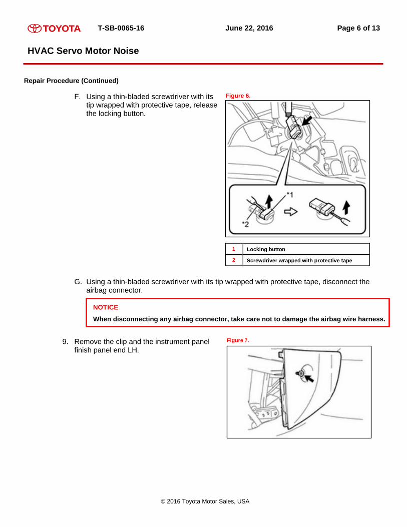
F. Using a thin-bladed screwdriver with its tip wrapped with protective tape, release the locking button.
Figure 6.
1 Locking button
2 Screwdriver wrapped with protective tape
G. Using a thin-bladed screwdriver with its tip wrapped with protective tape, disconnect the airbag connector.
9. Remove the clip and the instrument panel finish panel end LH.
Figure 7.
NOTICE
When disconnecting any airbag connector, take care not to damage the airbag wire harness.

T-SB-0065-16 June 22, 2016 Page 7 of 13
HVAC Servo Motor Noise
© 2016 Toyota Motor Sales, USA
Repair Procedure (Continued)
10. Remove the No. 3 air duct sub‐assembly.
A. Remove the clip.
B. Disengage the 3 claws to remove the
No. 3 air duct sub‐assembly.
Figure 8.
11. Remove the driver side HVAC servo motor.
A. Disconnect the servo motor connector.
B. Remove the 2 servo motor screws.
Figure 9.
1 Servo motor connector
2 Servo motor screws
1
NOTE
Once servo motor is removed, the gear on the HVAC case will drop down.
2

T-SB-0065-16 June 22, 2016 Page 8 of 13
HVAC Servo Motor Noise
© 2016 Toyota Motor Sales, USA
Repair Procedure (Continued)
12. Install the Driver Side HVAC Servo Motor.
A. Position the gear on the HVAC case to the initialized position.
(1) Use your finger and line up the top of the gear with the rib on the side of the HVAC case.
Figure 10.
(2) Hold the HVAC gear in the initialized position by gently placing bubble wrap, foam, paper, etc. (rolled up bubble wrap shown), between the inside of the gear and the HVAC case.
Figure 11.
1 Packing material (bubble wrap, foam, paper, etc.)
NOTICE
The NEW servo motor is in the initialized position.

T-SB-0065-16 June 22, 2016 Page 9 of 13
HVAC Servo Motor Noise
© 2016 Toyota Motor Sales, USA
Repair Procedure (Continued)
(3) Install the NEW servo motor by aligning the key feature on the servo motor gear with the corresponding key feature on the HVAC case gear.
Figure 12.
1 Align servo motor and HVAC case gear key features
Figure 13.
(4) Reinstall the 2 servo motor screws.
(5) Reconnect the servo motor connector.
(6) Remove the material (bubble wrap, foam, paper, etc.) used to hold the HVAC case gear in place.
B. Reinstall all driver side trim panels in the reverse order of removal.

T-SB-0065-16 June 22, 2016 Page 10 of 13
HVAC Servo Motor Noise
© 2016 Toyota Motor Sales, USA
Repair Procedure (Continued)
13. Disassemble the Passenger Side Trim Panel.
A. Remove the front door scuff plate RH.
(1) Disengage the 12 claws to remove the door scuff plate assembly RH.
Figure 14.
B. Remove the cowl side trim sub-assembly RH.
(1) Remove the clip.
(2) Disengage the claw and clip to remove the cowl side trim board RH.
Figure 15.
C. Remove the front door opening trim weather strip RH to the extent that allows removal of the instrument panel finish panel end.

T-SB-0065-16 June 22, 2016 Page 11 of 13
HVAC Servo Motor Noise
© 2016 Toyota Motor Sales, USA
Repair Procedure (Continued)
D. Remove the instrument side panel RH by disengage the 5 claws and 2 guides to remove the instrument side panel RH.
Figure 16.
E. Remove the glove compartment door sub-assembly.
(1) Remove the 2 bolts and 2 screws.
(2) Disengage the 2 claws and 3 guides to remove the glove compartment door sub-assembly.
Figure 17.
14. Install the Passenger Side Insulation Sheet.
The insulation sheet has adhesive applied to the top corners and bottom of the inside of the sheet. The adhesive areas are used to attach the insulation sheet in place.
Figure 18.
1 Insulation sheet, narrow side
2 Insulation sheet, wide side
3 Insulation sheet, bottom portion
2
3
1
NOTE
Adhesive side faces Servo Motor.

T-SB-0065-16 June 22, 2016 Page 12 of 13
HVAC Servo Motor Noise
© 2016 Toyota Motor Sales, USA
Repair Procedure (Continued)
15. Position the insulation sheet.
A. Place the narrow side of the insulation sheet adhesive against the center console/dash metal brace.
B. Place the wide side of the insulation sheet adhesive against the blower motor case covering the servo motor and wire harness.
Figure 19.
1 Center console/dash metal brace
2 Blower motor case
3 Top outer portion of plastic trim panel
(1) Place the bottom portion of the insulation sheet adhesive on the outside of the top plastic tim planel.
(2) Remove the three adhesive liners and ahere to the respecitve locations.
Figure 20.
16. Reinstall passenger side trim panels in the reverse order from removal.
17. Reconnect battery.
Torque: 5.4 N*m (55 kgf*cm, 48 in*lbf)

T-SB-0065-16 June 22, 2016 Page 13 of 13
HVAC Servo Motor Noise
© 2016 Toyota Motor Sales, USA
Repair Procedure (Continued)
18. Initalize all affected systems.
Refer to TIS, applicable model and model year Repair Manual:
2015 Sienna
General – Introduction – “Introduction: Repair Instruction: Initialization”
19. Verify normal operation of HVAC temperature control.
NOTE
Vehicle should be at normal operating temperature.