Embed Size (px)
Citation preview
www.danfoss.com/drives
to a safe installation. Danfoss supports your planning with our longstanding experience.
4 steps
Facility services design and project engineering of electrical drives
HVAC & Refrigeration applications
Engineering Guide

2
The removable design checklist at the back of this guide leads you to optimal design results in four steps.

3
Design aids ......................................................................................................................................................................................................6Part 1: Basics ....................................................................................................................................................................................................8
Reducing costs and increasing convenience ................................................................................................................................8Speed control saves energy .................................................................................................................................................................9Boosting cost effectiveness ................................................................................................................................................................10Achieving potential savings in practice ........................................................................................................................................11
Part 2: Four steps to an optimal system ........................................................................................................................................... 12Step 1: Practical aspects of AC mains systems .......................................................................................................................... 12
Recognising the actual mains configurationPractical aspects of electromagnetic compatibility (EMC) .................................................................................................. 13
Electromagnetic effects work in both directionsThe responsibility rests with the operatorTwo possible means of reductionDistinguishing between conducted and radiated interference ............................................................................................14Coupling mechanisms between electrical circuitsConductive couplingCapacative couplingRadiation coupling
Practical aspects of mains power quality .................................................................................................................................... 15Low-frequency mains interference
Supply networks at riskQuality assured by statutory provisionsHow mains interference occurs
Practical aspects of low- frequency mains interference ...................................................................................................... 16 Effects of mains interference
Undervoltage warningsHigher lossesAre interference- free frequency converters available ?
Analysing mains interference Practical aspects of mains interference reduction .................................................................................................................. 17
Options for reducing mains interferenceChokes at the input or in the DC linkRectifier with 12, 18 or 24 pulses per cyclePassive filtersAdvantages of passive filtersDrawbacks of passive filtersActive filters .........................................................................................................................................................................................18Advantages of active filtersDrawbacks of active filters
Current and Distortion Spectrum at Full loadSlim DC link .........................................................................................................................................................................................19Active front endAdvantages of AFE ....................................................................................................................................................................... 20Drawbacks of AFE
Practical aspects of high-frequency interference (RFI) ......................................................................................................... 21 Radio frequency interference
Standards and directives define limitsPractical aspects of 1st and 2nd environment .......................................................................................................................... 22
The operating site is the decisive factorEnvironment 1 (Class B): residential environmentEnvironment 2 (Class A): industrial environmentSpecial environmentsNo compromises
Practical aspects of mains protection measures ...................................................................................................................... 23Power factor correctionMains transients
Practical aspects of operation with a transformer or standby generator .................................................................... 24Maximum transformer utilisation
Transformer loadPower quality
Operation with a standby generator
Contents

4
Step 2: Practical aspects of ambient and environmental conditions ..............................................................................25The right installation location
Cabinet mount versus wall mountPractical aspects of enclosure ratings ...........................................................................................................................................26
IP rating scheme according to IEC 60529NEMA enclosure types according to NEMA 250-2003
Practical aspects of cooling design ................................................................................................................................................27Compliance with ambient temperature specificationsCoolingRelative humidity
Practical aspects of special requirements ...................................................................................................................................28Aggressive atmosphere or gasesDust exposure ...................................................................................................................................................................................... 29
Reduced coolingCooling fansFilter mats
Practical aspects of potentially explosive atmospheres .......................................................................................................30Potentially explosive atmospheres
Step 3: Practical aspects of motors and cabling .......................................................................................................................31Minimum efficiency classes for motors
Mandatory minimum efficienciesIE and Eff classes: major differences in detailsAffected three-phase motors
Practical aspects of IE classification of motors......................................................................................................................... 32Schedule for MEPS implementationCompliance with EN 50347 mounting dimension specificationsCost-effectiveness
Practical aspects of EC and PM motors ....................................................................................................................................... 33What are EC Motors ? Efficiency of EC MotorsPM-motors – an alternative to EC ?The Danfoss EC+ concept ............................................................................................................................................................. 34Does the best motor efficiency yield the best system efficiency ?
Practical aspects of motor suitability for frequency converter operation ....................................................................35Selection criteriaInsulation stressBearing stressThermal stress
Practical aspects of output filters .................................................................................................................................36Sine-wave and du/dt filters
Functions and tasks of sine-wave filtersWhen are sine-wave filters used?Retrofitting
Practical aspects of motor cables ...................................................................................................................................................37Rated voltageCable dimensioningMotor cable lengthEnergy savingsCables with suitable shielding
Practical aspects of earthing .............................................................................................................................................................38The importance of earthing
Electrically conductive materialsStar-configured earthing systemContact pointsConductor surface area
Contents

5
Practical aspects of shielding ...........................................................................................................................................................39The importance of shielding
Shielded cables and wiringShield connectionShield gapsGround connection .......................................................................................................................................................................... 40Motor supply cableSignal cableTypes of shields
Step 4: Practical aspects of frequency converter selection .................................................................................................41Basic designConstant or variable torque
Practical aspects of load curves for HVAC/R applications ...................................................................................................42Characteristic curves and applications
Practical aspects of multi-motor operation (special case) ...................................................................................................43DesignCable routing
Practical aspects of EMC measures ................................................................................................................................................44Putting theory into practiceRadio frequency interference
Practical recommendationsTwo approaches to RFI filters
Mains interference ............................................................................................................................................................................. 45The DC link affects mains interferenceReduction measuresMains chokesRectifiers with 12, 18 or 24 pulses per cycle............................................................................................................................. 46Passive filtersActive filters, active front ends and low harmonic drives
Practical aspects of residual current devices .............................................................................................................................47AC/DC residual current protective devices
Leakage current levelPractical aspects of earthing and motor protection ...............................................................................................................48
Earthing measures in practiceMotor protection and motor PTC thermistor
Practical aspects of operator control and data display .........................................................................................................49Simple operating concept
Operation under local control....................................................................................................................................................... 50Clear displayUniform conceptIntegrated in the cabinet door
Practical aspects of control and parameter configuration with a PC ..............................................................................51Extended options
Practical aspects of data exchange ................................................................................................................................................52Bus systems Better alarm managementBetter facility managementLower installation costsSimplified commissioning
Practical aspects of additional selection factors ......................................................................................................................53Process controllerMaintenanceStorage
VLT® HVAC Drive .........................................................................................................................................................................................54Directives related to frequency converters ....................................................................................................................................55Index.. ..............................................................................................................................................................................................................56Abbreviations ..............................................................................................................................................................................................59Notes.. .............................................................................................................................................................................................................60Design checklist ..........................................................................................................................................................................................62

6
Design aids for high-level and detailed designEngineering Guide for HVAC/R applicationsThe Danfoss Engineering Guide for HVAC and Refrigeration applications is aimed at engineering firms, public authorities, associations, plant en-gineers and electrical engineers actively involved in HVAC/R technol-ogy. It is conceived as a comprehen-sive aid for facility services designers (ICA and electrical) and project engineers whose scope of responsi-bility includes the project engineer-ing of variable-speed systems using frequency converters.
For this purpose, our specialists have coordinated the contents of this design manual with facility services designers in the industry in order to provide answers to important questions and achieve the greatest possible benefits for property
owners/developers and/or contract-ing authorities. The descriptions in the individual sections are intention-ally concise. They are not intended to serve as extensive explanations of technical matters, but instead to point out the relevant issues and specific requirements for project engineering. In this way, the Engineering Guide for HVAC/R applications provides assistance in the project engineering of frequency-controlled drives and in the assessment of the products of various manufacturers of frequency converters.
Project engineering of variable-speed drives often gives rise to questions that are not directly related to the actual tasks of a frequency converter. Instead, they relate to the integration
of these devices into the drive system and the overall facility. For this reason, it is essential to consider not only the frequency converter, but also the entire drive system. This system consists of a motor, a frequency converter, cabling, and the general conditions of the ambient situation, which includes the AC mains supply and the environmental conditions.
Project engineering and layout of variable-speed drive systems are of decisive importance. The decisions made by the facility services designer or project engineer at this stage are crucial with regard to the quality of the drive system, operating and maintenance costs, and reliable, trouble-free operation. Well-con-ceived project engineering before-
Anyone involved in the project engineering of frequency converters should give careful consideration to the general technical conditions of these devices.
hand helps avoiding undesirable side effects during subsequent operation of the drive system.
This engineering guide and included design checklist are ideal tools for achieving the best possible design reliability and thereby contributing to the operational reliability of the overall system.
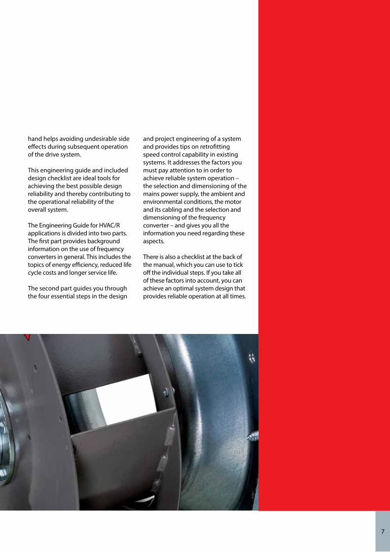
The Engineering Guide for HVAC/R applications is divided into two parts. The first part provides background information on the use of frequency converters in general. This includes the topics of energy efficiency, reduced life cycle costs and longer service life.
The second part guides you through the four essential steps in the design
and project engineering of a system and provides tips on retrofitting speed control capability in existing systems. It addresses the factors you must pay attention to in order to achieve reliable system operation – the selection and dimensioning of the mains power supply, the ambient and environmental conditions, the motor and its cabling and the selection and dimensioning of the frequency converter – and gives you all the information you need regarding these aspects.
There is also a checklist at the back of the manual, which you can use to tick off the individual steps. If you take all of these factors into account, you can achieve an optimal system design that provides reliable operation at all times.
7

8
Part 1: BasicsReducing costs and increasing convenience
Reduced system wearFrequency converters start and stop motors gently and smoothly. Unlike motors operated directly from the AC mains, motors driven by frequency converters do not cause torque or load shocks. This reduces the stress on the entire drive train (motor, gearbox, clutch, pump/fan/compressor) and piping system, including the seals. In this way, speed control significantly reduces wear and prolongs the lifetime of the system. Maintenance and repair costs are lower thanks to longer oper-ating periods and lower material wear.
Optimal operating point adjustmentThe efficiency of HVAC/R systems depends on the optimal operating point. This point varies depending on system capacity utilisation. The system works more efficiently when it runs closer to the optimal operating point. Thanks to their continuously variable speed, frequency converters can drive the system at exactly the optimal operating point.
Extended control rangeFrequency converters allow motors to be operated in the „oversynchro-nous“ range (output frequency above
50 Hz). This allows the output power to be boosted briefly. The extent to which oversynchronous operation is possible depends on the maximum output current and overload capacity of the frequency converter. In prac-tice, pumps, compressors and fans are often operated at a frequency range of 55-87 Hz. The motor manufacturer must always be consulted regarding motor suitability for oversynchronous operation.
Lower noise generationSystems running under partial load are quieter. Speed-controlled opera-tion significantly reduces acoustic noise generation.
Increased lifetimeDrive systems operating under partial load suffer less wear, which translates into longer service life. The reduced, optimised pressure also has a benefi-cial effect on the piping.
RetrofittingFrequency converters can usually be retrofitted in existing drive systems with little effort.
Compared with mechanical speed control systems, electronic speed control can save a lot of energy and substantially reduce wear. Both of these factors significantly reduce operating costs. The more often drive systems are operated (or must operate) under partial load, the higher the potential savings in terms of energy and mainte-nance costs. Due to the high potential for energy savings, the extra cost of an electronic speed control system can be recovered within a few months. In addition, modern systems have an extremely positive effect on many aspects of system processes and overall system availability.
High energy saving potentialWith an electronic speed control sys-tem, the flow, pressure or differential pressure can be matched to the actual demand. In practice, systems oper-ate predominantly under partial load rather than full load. In case of fans, pumps or compressors with variable torque characteristics, the extent of the energy savings depends on the difference between partial-load and full-load operation. The larger this is, the less time is required to recover the investment. It is typically around 12 months.
Start-up current limitingSwitching on equipment connected di-rectly to the AC mains generates peak currents that can be up to six to eight times greater than the rated current. Frequency converters limit the start-up current to the rated motor current. In this way they eliminate switch-on current peaks and avoid voltage sags due to transient heavy loading of the supply network. Eliminating these cur-rent peaks reduces the connected load of the pump system as seen by the electricity supplier, which reduces pro-vision costs and eliminates the need for supplementary Emax controllers.
Basics

9
Speed control saves energy
The energy saving potential when a frequency converter is used depends on the type of load being driven and the optimisation of the efficiency of the pump, compressor, fan or the motor by the frequency converter, as well as how much time the system operates under partial load. Many systems are designed for rarely-occur-ring peak loads, so they are usually operated under partial load.
Centrifugal pumps and fans offer the largest potential for energy savings. They fall in the class of fluid flow machines with variable torque curves, which are subject to the following proportionality rules.
The flow increases linearly with increasing speed (rpm), while the pressure increases quadratically and the power consumption increases cubically.The decisive factor for energy savings is the cubic relationship between rpm and power consumption.
A pump running at half its rated speed, for example, needs only one-eighth of the power necessary for operation at its rated speed. Even small reductions in speed thus lead to significant energy savings. For example, a 20% speed reduction yields 50% energy savings. The main benefit of using a frequency converter is that speed control does not waste power (unlike regulation with a throttle valve or damper, for exam-ple), but instead adjusts the motor power to match exactly the actual demand.
Additional energy savings can be achieved by optimising the efficiency of the fan, pump or motor with frequency converter operation. The voltage control characteristic (V/f curve) supplies the right voltage to the motor for every frequency (and thus motor speed). In this way, the controller avoids motor losses resulting from excessive reactive current.
Remark: Danfoss VLT® HVAC Drive frequency converters optimise energy demand even further. The Automatic Energy Optimisation (AEO) function constantly adjusts the current motor voltage so the motor runs with the highest possible effi-ciency. In this way, the VLT® HVAC Drive always adapts the voltage to the actual load conditions it measures. The additional energy saving potential amounts to an extra 3 to 5%.
For calculation of expected energy savings when using frequency converters, tools like the Danfoss VLT® Energy Box Software are available.
Speed n [%]
Q, p
, P [%
]
100
60
80
40
20
0
10060 8040200
Q
P
p
Proportionality rules of fluid flow machines. Due to the physical relationships, the throughput Q, pressure p and power P are directly dependent on the machine speed with fluid flow machines.

10
LCC = Cic + Cin + Ce + Co + Cm + Cs + Cenv + Cd
Cic = initial capital cost (procurement cost)
Cin = installation and commissioning costs
Ce = energy cost Cs = downtime and lost production costs
Co = operating cost Cenv = environmental cost
Cm = maintenance cost Cd = decommissioning and disposal costs
Boosting cost effectiveness
Life cycle cost calculation
In addition to the pump and system characteristic curves, this plot shows several efficiency levels. Both valve control and speed control cause the operating point to move out of the optimum efficiency range.
84%
70%
80%
84%
80%
]Pr
essu
re [b
ar]
Efficiency range
Pump curve
Valve control
Set point
System curve
Speed control
Flow [Q]
Life cycle cost (LCC) analysisUntil a few years ago, plant engineers and operators only considered procurement and installation costs when selecting a pump system. Today a full analysis of all costs is becoming increasingly common. Under the name “life cycle cost” (LCC), this form of analysis includes all costs incurred by pump systems during their operational life.
A life cycle cost analysis includes not only the procurement and installation costs, but also the costs of energy, operation, maintenance, downtime, the environment, and disposal. Two factors – energy cost and mainte-nance cost – have a decisive effect on the life cycle cost. Operators look for innovative controlled pump drives in order to reduce these costs.
a) Valve control: η decreases b) Actual speed control: η curve not aligned to system curvec) Optimal speed control: η curve nearly matches system curve
a)
c)
b)
84%
70%
84%
80%
80%
60%
84%
70%80% 84%
50%
60%
70%84%
Pow
er
Speed [n]
Efficiency range
Reducing energy costsOne of the largest cost factors in the life cycle cost formula is the energy cost. This is especially true when fans, pump systems or compressors run more than 2000 hours per year.
Most existing applications have substantial dormant energy saving potential. This arises from the fact that most systems are overdimensioned because they are designed for worst-case conditions. The volumetric flow
is often regulated by a throttle valve. With this form of regulation, the pump always runs at full capacity and thus consumes energy unnecessarily.
This is comparable to driving a car with the engine always running at full throttle and using the brakes to adjust the speed. Modern, intelligent frequency converters offer ideal means to reduce energy consumption as well as maintenance costs.
Example of reduced LCC:The VLT® HVAC Drive has a square-root function for converting differential pressure readings into to a volumetric flow signal. This allows users to install less expen-sive sensors in order to reduce procurement costs (Cic).
Basics

Achieving potential savings in practiceThe descriptions in the first part of this design considerations focus primarily on the fundamentals and potential savings in HVAC technology.
Among other things, they deal with life cycle costs, reducing energy con-sumption and reducing energy costs and reducing service and mainte-nance costs. Your task now is to carry out considered, intelligent design in order to achieve these potential benefits in reality.
To this end, the second part of this manual guides you through the design process in four steps.
The following sections:– Mains systems– Ambient and environmental conditions – Motors and cables– Frequency converters give you all
the information about character-istics and data that you need for component selection and dimen-sioning in order to ensure reliable system operation.
In places where more detailed know-ledge is advantageous, we provide references to additional documents in addition to the basic information in this manual.
The checklist included at the end of this manual, which you can fold out or tear out, is also a handy aid where you can tick off the individual steps. This gives you a quick and easy overview of all relevant design factors.
By taking all these factors into account, you put yourself in an ideal position to design a reliable and energy-efficient system.

12
Part 2 : Four steps to an optimal systemStep 1: Practical aspects of AC mains systemsRecognising the actual mains configurationVarious types of AC mains systems are used to supply power to electrical drives. They all affect the EMC characteristics of the system to various degrees. The five-wire TN-S system is the best in this regard, while the isolated IT system is the least desirable.
TN mains systemsThere are two versions of this form of mains distribution system: TN-S and TN-C.
TN-SThis is a five-wire system with sepa-rate neutral (N) and protective earth (PE) conductors.It thus provides the best EMC proper-ties and avoids the transmission of interference.
TN-CThis is a four-wire system with a com-mon neutral and protective earth con-ductor throughout the entire system.Due to the combined neutral and pro-tective earth conductor, a TN-C system does not have good EMC characteris-tics.
TT mains systemsThis is a four-wire system with an earthed neutral conductor and indi-vidual earthing of the drive units.This system has good EMC character-istics if the earthing is implemented properly.
IT mains systemThis is an isolated four-wire system with the neutral conductor either not earthed or earthed via an impedance.
L1
L2
L3
N
PE
L1
L2
L3
N
L1
L2
L3
N
L1
L2
L3
PEN
TN-S-System Seperate neutral (N) and protective earth (PE) conductor
TT-System Earthed neutral conductor and individual earthing of drive units
IT-System Isolated system with the neutral conductor either not earthed or earthed via an impendance.
TN-C-System Combined neutral and protective earth conductor to one common conductor throughout the entire system
L1
L2
L3
N
PE
L1
L2
L3
N
L1
L2
L3
N
L1
L2
L3
PEN
TN-S-System Seperate neutral (N) and protective earth (PE) conductor
TT-System Earthed neutral conductor and individual earthing of drive units
IT-System Isolated system with the neutral conductor either not earthed or earthed via an impendance.
TN-C-System Combined neutral and protective earth conductor to one common conductor throughout the entire system
Note: All EMC features of the frequency converter (filters, etc.) must be disabled when it is used in an IT mains system.
Forms of electrical mains systems according to EN 50310 / HD 384.3
Step 1

13
Electromagnetic effects work in both directionsSystem components affect each other: every device generates interference and is affected by interference. In addition to the type and amount of interference an assembly generates, it is characterised by its immunity to interference from nearby assemblies.
The responsibility rests with the operatorPreviously, the manufacturer of a component or assembly for electrical drives had to take countermeasures to comply with statutory standards. With the introduction of the EN 61800-3 standard for variable-speed drive systems, this responsibility has been transferred to the end user or operator of the system. Now manufacturers only have to offer solutions for operation
conforming to the standard. Remedy-ing any interference that may occur (in other words, using these solutions), along with the resulting costs, is the responsibility of the operator.
Two possible means of reductionUsers and plant engineers have two options for ensuring electromagnetic compatibility. One option is to stop interference at the source by minimis-ing or eliminating the emitted interference. The other option is to increase the interference immunity of the device or system affected by interference by preventing or sub-stantially reducing the reception of interference.
Eliminating radio interference
Radioactivity Resistance to interference
Harmonic distortion Protection against contact
Microwaves NEMP
TEMPEST
Lightning protection Biological eects
Corona Electrostatic
Magnetic elds Electrical corrosion EMC
Every electrical device generates electrical and magnetic fields that affect its direct environment to a certain extent.
The magnitude and consequences of these effects depend on the power and the design of the device. In electrical machinery and systems, interactions between electrical or electronic assemblies may impair or prevent reliable, trouble-free opera-tion. It is therefore important for operators, designers and plant engineers to understand the mecha-nisms of these interactions. Only then will they be able to take appropriate, cost-effective countermeasures at the design stage.
This is because the cost of suitable measures increases with each stage of the process.
Electromagnetic compatibility (EMC) encompasses a wide variety of factors. The most significant factors in drive engineering are mains interference, RFI suppression and interference immunity.
Practical aspects of electromagnetic compatibility (EMC)

14
Practical aspects of electromagnetic compatibility (EMC)
Distinguishing between conducted and radiated interferenceThere are always interactions when several systems are present. Experts distinguish between the interference source and the interference sink, which in practice usually means the device causing the interference and the device affected by it. All types of electrical and magnetic quantities can potentially cause interference. For example, interference may take the form of mains harmonics, electrostatic discharges, rapid voltage fluctuations, high-frequency interference or interference fields. In practice, mains harmonics are often referred to as mains interference, harmonic over-tones or simply harmonics.
Coupling mechanisms between electrical circuitsNow you’re probably wondering how interference is transmitted. As a form of electromagnetic emission, it can essentially be transmitted by conduc-tors, electric fields, or electromagnetic waves. In technical terms, these are called conductive, capacitive and/or inductive coupling, and radiation coupling, which means an interaction between different circuits in which electromagnetic energy flows from one circuit to another one. Conductive couplingConductive coupling occurs when two or more electrical circuits are con-nected to one another by a common conductor, such as a potential equali-sation cable.
Capacitive couplingCapacitive coupling results from volt-age differences between the circuits.Inductive coupling occurs between two current-carrying conductors.
Radiation couplingRadiation coupling occurs when an interference sink is located in the far-field region of an electromagnetic field generated by an interference source.For the purpose of electromagnetic analysis, the standard specifies 30 MHz as the boundary between conductive coupling and radiation
Interference diffusion paths
Electromagnetic interference occurs over the entire frequency range, but the propagation paths and form of diffusion vary.
Cable conducted interference
(Mains cables, Control cables)
10 kHz 100 kHz 1 MHz 10 MHz 30 Mhz 100 MHz
300 MHz 1GHz
Radiation interference (airborn)
Frequency converters and EMCLow-frequency effects (conductive) Mains interference/harmonicsHigh-frequency effects (radiation) Radio frequency interference (emission of electromagnetic fields)
Source of interference
Switching circuit partsPower convertersFrequency convertersIgnition systemsRadio telephonesMobile phonesComputersSwitch mode power supplies
Interference sink
e.g.:Control systemsPower convertersFrequency convertersGeneral radio recei-ving systemsMobile phonesData/ phone trans-mission wires
Interference couplinge.g. conductive, capacitive, inductive or electromagnetic
oversættelse:e.g.:
coupling. This corresponds to a wavelength of 10 metres. Below this frequency, electromagnetic interfer-ence is mainly propagated through conductors or coupled by electrical or magnetic fields. Above 30 MHz, wires and cables act as aerials and emit electromagnetic waves.
Overview of coupling paths for electromagnetic interference and typical examples
Step 1

Practical aspects of mains power quality
Measurements show distinct distortion of the mains voltage waveform due to interference from nonlinear loads.
The ideal situation of a sinusoidal mains voltage is rarely found nowadays in our mains grids.
Low-frequency mains interferenceSupply networks at riskThe mains voltage supplied by electricity companies to homes, businesses and industry should be a uniform sinusoidal voltage with constant amplitude and frequency. This ideal situation is no longer found in public power grids. This is due in part to loads that draw non-sinusoidal currents from the mains or have non-linear characteristics, such as PCs, television sets, switching power supplies, energy-efficient lamps, and frequency converters. Mains power quality will decline even more in the future due to the European energy network, higher grid utilisation and reduced investments. Deviations from the ideal sinusoidal waveform are therefore unavoidable and permissi-ble within certain limits.
Facility services designers and operators have an obligation to keep mains interference to a minimum. But what are the limits and who specifies them?
Quality assured by statutory provisionsStandards, directives and regulations are helpful in any discussion regarding clean, high-quality mains power. In most of Europe the basis for the objective assessment of the quality of mains power is the Electromagnetic Compatibility of Devices Act. European standards EN 61000-2-2, EN 61000-2-4 and EN 50160 define the mains voltage limits that must be observed in public and industrial power grids.
The EN 61000-3-2 and 61000-3-12 standards are the regulations concern-ing mains interference generated by connected devices. Facility operators must also take the EN 50178 standard and the connection conditions of the electricity company into account in the overall analysis. The basic assumption is that compliance with these levels ensures that all devices and systems connected to electrical distribution systems will fulfil their intended purpose without problems.
How mains interference occursSpecialists refer to the distortion of the sinusoidal waveform in mains systems caused by the pulsating input currents of the connected loads as “mains interference” or “harmonics”. They also call this the harmonic content on the mains, which is derived from Fourier analysis, and they assess it up to 2.5 kHz, corre-sponding to the 50th harmonic of the mains frequency.
The input rectifiers of frequency con-verters generate this typical form of harmonic interference on the mains. Where frequency converters are con-nected to 50-Hz mains systems, the third harmonic (150 Hz), fifth har-monic (250 Hz) or seventh harmonic (350 Hz) are considered. This is where the effects are the strongest. The total harmonic content is also called the total harmonic distortion (THD).
15
16
Practical aspects of low-frequency mains interference
Effects of mains interferenceHarmonics and voltage fluctuations are two forms of low-frequency conducted mains interference. They have a different appearance at their origin than at any other point in the mains system where a load is con-nected.
Consequently, the mains feed, mains structure and loads must all be taken into account collectively when assessing mains interference.The effects of an elevated harmonic level are described below.
Undervoltage warnings– Incorrect voltage measurements
due to distortion of the sinusoidal mains voltage.
– Reduced mains power capacity
Higher losses– Harmonics take an additional share
of the active power, apparent power and reactive power
– Shorter lifetime of devices and com-ponents, for example as a result of additional heating effects due to resonances.
– Malfunction or damage to electrical or electronic loads (such as a hum-ming sound in other devices). In the worst case, even destruction.
– Incorrect measurements because only true-RMS instruments and meas-uring systems take harmonic content into account.
Are interference-free frequency converters available?Every frequency converter gener-ates mains interference. However, the present standard only considers the frequency range up to 2 kHz. For this reason, some manufacturers shift the mains interference into the region above 2 kHz, which is not addressed by the standard, and advertise them as „interference-free“ devices. Limits for this region are currently being studied.
Note: Excessive harmonic content puts a load on power factor correction equipment and may even case its destruction. For this reason, they should be fitted with chokes.
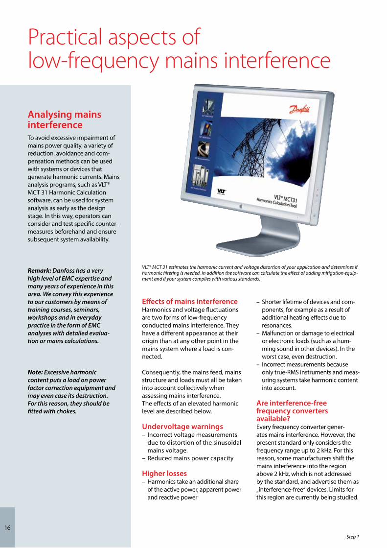
VLT® MCT 31 estimates the harmonic current and voltage distortion of your application and determines if harmonic filtering is needed. In addition the software can calculate the effect of adding mitigation equip-ment and if your system complies with various standards.
Analysing mains interferenceTo avoid excessive impairment of mains power quality, a variety of reduction, avoidance and com-pensation methods can be used with systems or devices that generate harmonic currents. Mains analysis programs, such as VLT® MCT 31 Harmonic Calculation software, can be used for system analysis as early as the design stage. In this way, operators can consider and test specific counter-measures beforehand and ensure subsequent system availability.
Remark: Danfoss has a very high level of EMC expertise and many years of experience in this area. We convey this experience to our customers by means of training courses, seminars, workshops and in everyday practice in the form of EMC analyses with detailed evalua-tion or mains calculations.
Step 1

Practical aspects of mains interference reductionOptions for reducing mains interferenceGenerally speaking, mains interfer-ence from electronic power control-lers can be reduced by limiting the amplitude of pulsed currents. This improves the power factor λ (lambda). To avoid excessive impairment of mains power quality, a variety of reduction, avoidance or compensa-tion methods can be used with systems and devices that generate harmonics.
– Chokes at the input or in the DC link of frequency converters
– Slim DC links– Rectifiers with 12, 18 or
24 pulses per cycle– Passive filters– Active filters– Active front end and
VLT® Low Harmonic Drives
Chokes at the input or in the DC linkEven simple chokes can effectively reduce the level of harmonics fed back into the mains system by rectifier circuits as mains interference. Fre-quency converter manufacturers usually offer them as supplementary options or retrofits.
The chokes can be connected ahead of the frequency converter (on the feed side) or in the DC link after the rectifier. As the inductance has the same effect in either location, the attenuation of the mains interference is independent of where the choke is installed.
Each option has advantages and drawbacks. Input chokes are more expensive, larger, and generate higher losses than DC chokes. Their advan-tage is that they also protect the rectifier against mains transients. DC chokes are located in the DC link. They are more effective, but they usually cannot be retrofitted. With these chokes, the total harmonic distortion
from a B6 rectifier can be reduced from a THD of 80% without chokes to approximately 40%. Chokes with a Uk of 4% have proven to be effective for use in frequency converters. Further reduction can only be achieved with specially adapted filters.
Rectifier with 12, 18 or 24 pulses per cycleRectifier circuits with a high number of pulses per cycle (12, 18 or 24) generate lower harmonic levels. They have often been used in high-power applications in the past.
However, they must be fed from special transformers with multiple phase-offset secondary windings that provide all the necessary power to the rectifier stage. In addition to the complexity and size of the special transformer, the disadvantages of this technology include higher invest-ment costs for the transformer and the frequency converter.
Passive filtersWhere there are especially stringent harmonic distortion limit require-ments, passive mains interference filters are available as options. They consist of passive components, such as coils and capacitors.
Series LC circuits specifically tuned to the individual harmonic frequencies and connected in parallel with the load reduce the total harmonic distortion (THD) at the mains input to
10% or 5%. Filter modules can be used with individual frequency converters or groups of frequency converters. To obtain the best possible results with a harmonic filter, it must be matched to the input current actually drawn by the fre-quency converter.
In terms of circuit design, passive harmonic filters are installed ahead of a frequency converter or a group of frequency converters.
Advantages of passive filtersThis type of filter offers a good price/performance ratio. At relatively low cost, the operator can obtain a reduction in harmonic levels compara-ble to what is possible with 12- or 18-pulse/cycle rectifiers. The total harmonic distortion (THD) can be reduced to 5%.
Passive filters do not generate interference in the frequency range above 2 kHz. As they consist entirely of passive components, there is no wear and they are immune to electri-cal interference and mechanical stress.
Drawbacks of passive filtersDue to their design, passive filters are relatively large and heavy. Filters of this type are very effective in the load range of 80–100%. However, the capacitive reactive power increases with decreasing load and it is recom-mended that you disconnect the filter capacitors in no-load operation.
Remark: Danfoss VLT frequency converters are equipped with DC link chokes as standard. They reduce the mains interference to a THDi of 40%.

18
Active filtersWhen requirements with regard tomains interference are even more stringent, active electronic filtersare used. Active filters are electronic absorption circuits that the user connects in parallel with the har-monic generators. They analyse the harmonic current generated by the nonlinear load and supply an offset-ting compensation current. This current fully neutralises the corre-sponding harmonic current at the connection point.The degree of compensation is adjustable. In this way harmonics can be almost completely compensated if so desired, or (perhaps for economic reasons) only to the extent necessary to enable the system to comply with statutory limits. Here again it must be borne in mind that these filters operate with clock frequencies and produce mains interference in the 4–18 kHz range.
Advantages of active filtersOperators can incorporate active filters at any desired location in the mains system as central measures, depending on whether they wish to compensate individual drives, entire groups, or even an entire distribution system. It is not necessary to provide a separate filter for each frequency converter. The total harmonic distor-tion drops to a THD level ≤ 4%.
Drawbacks of active filtersOne drawback is the relatively high investment cost. In addition, these filters are not effective above the 25th harmonic level. The effects above 2 kHz generated by the filters them-selves must also be taken into account with active filter technology. They may require further measures to keep the mains system clean.
Practical aspects of mains interference reduction
Current and Distortion Spectrum at Full Load
Typical without filter With AHF 010
With AHF 010
With AHF 005
With AHF 005
Advanced Harmonic Filters (AHF) reduce the total harmonic current distortion to 5% or 10% at 100% load.
Without filter
M3-
M3-
M3-
M3-
M3-
Supply
Central compensation
Group compensation
Individual compensation
Active filters can be installed at any desired point in the mains system, depending on whether they should provide compensation for individual drives, entire groups, or even entire mains sys-tems.
Step 1

19
Slim DC linkRecent years have seen the increasing availability of frequency converters with a“slim” DC link. In this approach, manufacturers greatly reduce the capacitance of the DC link capacitors. Even without a choke, this reduces the fifth harmonic of the current to a THD level below 40%.However, it causes mains interference in the high frequency range that would otherwise not occur. Due to the broad frequency spectrum of devices with slim DC links, there is a greater risk of resonances with other components connected to the mains, such as fluorescent lamps or trans-formers. Devising suitable measures is correspondingly time-consuming and very difficult.
In addition, converters with slim DC links have weaknesses on the load side. With converters of this sort, load variations result in significantly larger voltage variations. As a result, they have a greater tendency to oscillate in response to load variations on the motor shaft. Load shedding is also difficult. During load shedding the motor acts as a generator with high peak voltages. In response to this, devices with lean DC links shut down faster than conventional devices in order to protect against destruction due to overload or overvoltage.Due to the small or zero capacitance, converters with slim DC links are not good at riding through mains drop-outs. As a rule of thumb, a slim DC link has around 10% of the capacitance of a conventional DC link.
In addition to mains interference due to the input current, converters with slim DC links pollute the mains with the switching frequency of the motor-side inverter. This is clearly visible on the mains side due to the low or zero capacitance of the DC link.
Active Front End`Low Harmonic Drives´ (LHD) is often used when describing Active Front End (AFE) drives. However, this is a bit mis-leading as Low Harmonic Drives might cover many different technologies and include both passive and active mitiga-tion. Active Front End drives have IGBT switches on the drive input circuits that replaces conventional rectifiers. These circuits use semiconductor devices with fast switching characteristics to force the input current to be approxi-mately sinusoidal and they are very
Converters with slim DC links generate higher harmonic levels, especially in the higher frequency ranges.
Conventional DC link Slim DC link
effective in attenuating low-frequency mains interference. Like frequency converters with slim DC links, they gen-erate mains interference in the high frequency range.
An active front end is the most expensive approach to reducing mains interference, since it amounts to a supplementary, full-fledged frequency converter that is able to feed power back into the mains system.The low harmonic drive option does not offer this capability and is accord-ingly somewhat less costly.
– Slim DC link
20
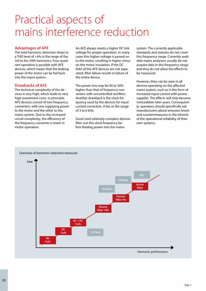
Advantages of AFE The total harmonic distortion drops to a THD level of <4% in the range of the 3rd to the 50th harmonics. Four-quad-rant operation is possible with AFE devices, which means that the braking power of the motor can be fed back into the mains system.
Drawbacks of AFE The technical complexity of the de-vices is very high, which leads to very high investment costs. In principle, AFE devices consist of two frequency converters, with one supplying power to the motor and the other to the mains system. Due to the increased circuit complexity, the efficiency of the frequency converter is lower in motor operation.
Practical aspects of mains interference reduction
Cost
Harmonic performance
Active Filter
PassiveFilter 5%
PassiveFilter 10%
AC + DCCoils
12-PulseDC
Coils
NoCoils
18-Pulse
24-Pulse
AFE
An AFE always needs a higher DC link voltage for proper operation. In many cases this higher voltage is passed on to the motor, resulting in higher stress on the motor insulation. If the DC links of the AFE devices are not sepa-rated, filter failure results in failure of the entire device. The power loss may be 40 to 50% higher than that of frequency con-verters with uncontrolled rectifiers. Another drawback is the clock fre-quency used by the devices for input current correction. It lies in the range of 3 to 6 kHz.
Good (and relatively complex) devices filter out this clock frequency be-fore feeding power into the mains
system. The currently applicable standards and statutes do not cover this frequency range. Currently avail-able mains analysers usually do not acquire data in this frequency range and thus do not allow the effects to be measured.
However, they can be seen in all devices operating on the affected mains system, such as in the form of increased input current with power supplies. The effects will only become noticeablein later years. Consequent-ly, operators should specifically ask manufacturers about emission levels and countermeasures in the interest of the operational reliability of their own systems.
Overview of harmonic reduction measures
Harmonic performance
Step 1

21
Practical aspects of high-frequency interference (RFI)
Classification of the new categories C1 to C4 of the EN 61800-3 product standard
Still valid Product standard as obligatory from 2007
EN 55011Basic environment
standard
Class B(Residential environment)
1st environment(Residential environment)
2nd environment(Industrial environment)
Class A(Industrial environment)
EN 61800-3(revised standard)
Group 1+2
Group 1(HF Internal)
Group 2(HF External)
Category C2
Category C1
Category C3
Category C4
Comparison of the new categories C1 to C4 defined by the EN 61800-3 product standard and classes A and B of the EN 55011 environment standard.
Comparision of interference levels
Radio frequency interferenceFrequency converters generate variable rotating field frequencies at corresponding motor voltages due to variable-width rectangular current pulses. The steep pulse edges contain high-frequency components. Motor cables and frequency converters radiate these components and conduct them into the mains system via the cable.
the mains cable or by radiation from the mains cable.
The filters are intended to limit these interference emissions to a specified statutory level, which means that as much as possible they should be fitted in the equipment as standard. As with mains chokes, with RFI filters the quality of the filter to be used must be clearly defined.
Specific limits for interference levels are defined in the EN 61800-3 product standard and the EN 55011 generic standard.
Standards and directives define limitsTwo standards must be observed for the comprehensive assessment of ra-dio frequency interference. The first is the EN 55011 environment standard, which defines the limits according to the basic environment: either indus-trial (classes A1 and A2) or residential (class B). In addition, the EN-61800-3 product standard for electrical drive systems, which came into effect in June 2007, defines new categories (C1 to C4) for device application areas.
Although they are comparable to the previous classes in terms of limits, they allow a wider range of applica-tion within the scope of the product standard.
Manufacturers use radio frequency interference (RFI) filters (also called mains filters or EMC filters) to reduce the level of this type of interference on the mains feed.
They serve to protect devices against high-frequency conducted interfer-ence (noise immunity) and to reduce the amount of high-frequency interference emitted by a device over
Note: Facility operators must comply with EN 55011 in case of problems. Converter manufacturers must conform to EN 61800-3.
EN 61800-3 product standard (2005-07) for electrical drive systems
Classificationby category C1 C2 C3 C4
Environment 1st Environment1st or 2nd
Environment (operator decision)
2nd Environment 2nd Environment
Voltage/current < 1000 V> 1000 V
In > 400 AConnection to IT
networkEMCexpertise
Norequirement
Installation and commissioning byan EMC expert
EMC plan required
Limits according toEN 55011
Class BClass A1
(plus warning notice)
Class A2(plus warning
notice)
Values exceed
Class A2
22
Practical aspects of 1st and 2nd environment
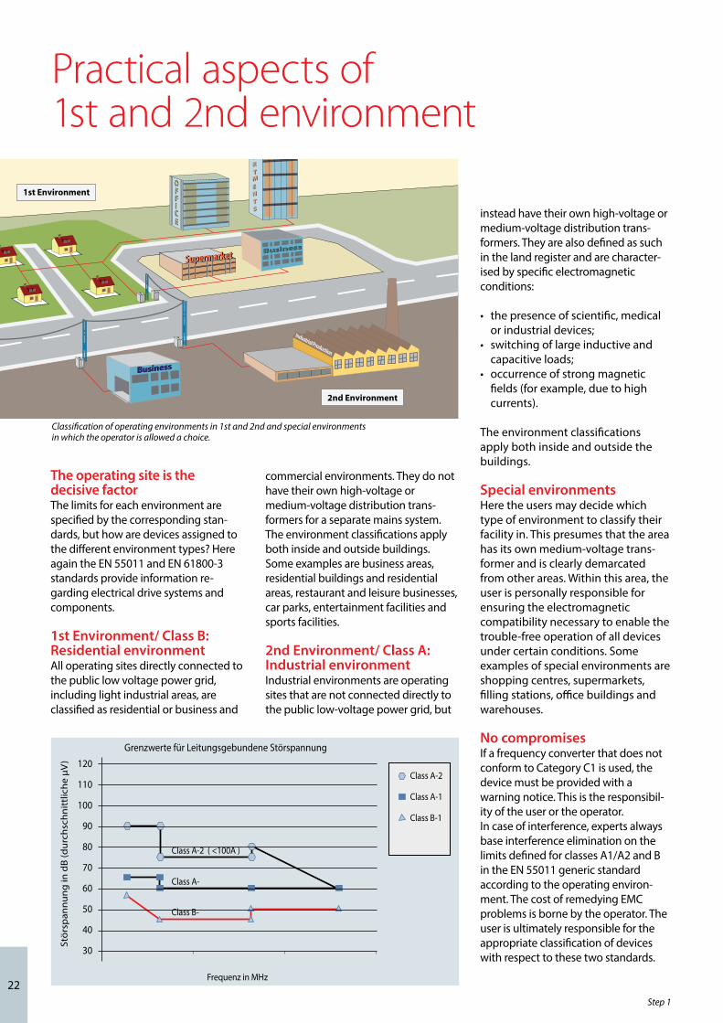
The operating site is the decisive factorThe limits for each environment are specified by the corresponding stan-dards, but how are devices assigned to the different environment types? Here again the EN 55011 and EN 61800-3 standards provide information re-garding electrical drive systems and components.
1st Environment/ Class B:Residential environmentAll operating sites directly connected to the public low voltage power grid, including light industrial areas, are classified as residential or business and
commercial environments. They do not have their own high-voltage or medium-voltage distribution trans-formers for a separate mains system.The environment classifications apply both inside and outside buildings. Some examples are business areas, residential buildings and residential areas, restaurant and leisure businesses, car parks, entertainment facilities and sports facilities.
2nd Environment/ Class A: Industrial environmentIndustrial environments are operating sites that are not connected directly to the public low-voltage power grid, but
1. UMGEBUNG
T
2nd Environment
1st Environment
SupermarketSupermarket
Industrial Production
BusinessBusiness
BusinessBusiness
T
T
T
FFFFII
OO
CCEE
Appartments
AAPPPPAARR
TTMM
EENN
TTSS
Grenzwerte für Leitungsgebundene Störspannung
120
110
100
90
80
70
60
50
40
30
Frequenz in MHz
Stö
rsp
ann
un
g in
dB
(du
rch
sch
nit
tlic
he
µV
)
Class A-2
Class A-1
Class B-1
Class A-2 ( <100A )
Class A-
Class B-
instead have their own high-voltage or medium-voltage distribution trans-formers. They are also defined as such in the land register and are character-ised by specific electromagnetic conditions:
• the presence of scientific, medical or industrial devices;
• switching of large inductive and capacitive loads;• occurrence of strong magnetic
fields (for example, due to high currents).
The environment classifications apply both inside and outside the buildings.
Special environments Here the users may decide which type of environment to classify their facility in. This presumes that the area has its own medium-voltage trans-former and is clearly demarcated from other areas. Within this area, the user is personally responsible for ensuring the electromagnetic compatibility necessary to enable the trouble-free operation of all devices under certain conditions. Some examples of special environments are shopping centres, supermarkets, filling stations, office buildings and warehouses.
No compromisesIf a frequency converter that does not conform to Category C1 is used, the device must be provided with a warning notice. This is the responsibil-ity of the user or the operator.In case of interference, experts always base interference elimination on the limits defined for classes A1/A2 and B in the EN 55011 generic standard according to the operating environ-ment. The cost of remedying EMC problems is borne by the operator. The user is ultimately responsible for the appropriate classification of devices with respect to these two standards.
Classification of operating environments in 1st and 2nd and special environments in which the operator is allowed a choice.
Step 1

Transients
t
U
23
Lighting strikes are the most frequent cause of mains transients in systems
Practical aspectsof mains protection measuresPower factor correctionPower factor correction equipment serves to reduce the phase shift (φ) between the voltage and the current and moves power factor closer to unity (cos φ). This is necessary when a large number of inductive loads, such as motors or lamp ballasts, are used in an electrical distribution system.Depending on the design of the DC link, frequency converters do not draw any reactive power from the mains system or generate any phase shift. They have a cos φ of approxi-mately 1. For this reason, users of speed-controlled motors do not have to take them into account when dimensioning any power factor correction equipment that may be necessary. However, the current drawn by the phase correction equipment rises because frequency converters generate harmonics. The load on the capacitors increases as the number of harmonic generators increases, and they heat up more. For these reasons, the operator must fit chokes in power factor correction equipment. These chokes also prevent resonances between load inductances and the capacitance of the power factor correction equipment.
Converters with cos j < 1 also require chokes in the power factor correction
equipment. The user must take the higher reactive power level into account when dimensioning the cables.
Mains transientsTransients are brief voltage peaks in the range of a few thousand volts. They can occur in all types of power distribution systems, in both indus-trial and residential environments. Lightning strikes are a common cause of transients. However, they are also caused by switching large loads on line or off line or switching other equipment, such as power factor correction equipment. Short circuits, tripping of circuit breakers in power distribution systems, and inductive coupling between parallel cables can also cause transients.
The EN 61000-4-1 standard describes the forms of these transients and how much energy they contain. Their harmful effects can be limited by various methods. Gas-filled surge arresters and spark gaps are used to provide first-level protection against high-energy transients. For second-level protection, most electronic devices use voltage-dependent resistors (varistors) to attenuate transients. Frequency converters also utilise this method.

24
Practical aspects of operation with a transformer or standby generator
In low-voltage systems (400 V, 500 V and 690 V), operators may use speed-controlled drives with ratings up to around1 MW. A transformer converts the voltage of the medium-voltage grid to the required voltage.In the public power grid (environment 1: residential environment) this is the responsibility of the electricity company.
In industrial mains systems (environ-ment 2: industrial environment; usually 500 V or 690 V), the trans-former is located on the premises of the end user, who is also responsible for feeding power to the user’s facility.
Transformer loadIn case of transformers that supply power to frequency converters, it must be borne in mind that the use of frequency converters and other rectifier loads causes the generation of harmonics that put an extra reactive power load on the trans-former.
This causes higher losses and addi-tional heating. In the worst case, this can lead to the destruction of the transformer. Intelligent vector groups (several transformers connected together) may also generate harmon-ics under certain conditions.
Remark: All frequency converters in the VLT® HVAC Drive series are equipped with integrated mains interference chokes as standard.
Power qualityTo ensure the quality of the mains power in accordance with the applicable standards, you need to know how much frequency converter load the transformer can handle.
Mains analysis programs such as the VLT® MCT 31 Harmonic Calculation software provide an exact indication of how much frequency converter load a transformer can supply in a specific system.
Maximum transformer utilisation
Operators use backup power systems when the continued operation of mains-powered devices is necessary even in the event of mains failure. They are also used when the available mains connection cannot provide sufficient power. Operation in parallel with the public power grid is also possible in order to achieve higher mains power. This is common practice when heat is also needed, such as with combined heat and power units. They take advantage of the high efficiency that can be achieved with this form of energy conversion.When backup power is provided by a generator, the mains impedance is usually higher than when power is taken from public grid. This causes the total harmonic distortion to increase. With proper design, generators can operate in a system containing harmonic generators.
In practice, this means that when the system is switched from mains operation to generator feed, the harmonic load can usually be expected to increase.
Facility services designers and opera-tors should calculate or measure the increase in the harmonic load in order to ensure that the power quality conforms to regulations and thereby to prevent problems and equipment failure.
Asymmetric loading of the genera-tor must be avoided, since it causes increased losses and may cause the total harmonic distortion to increase.A 5/6 stagger of the generator wind-ing attenuates the fifth and seventh harmonics, but it allows the third harmonic to increase. A 2/3 stagger reduces the third harmonic.
If possible, the operator should disconnect power factor correction
equipment because resonances may occur in the system.Chokes or active absorption filters can attenuate harmonics. Resistive loads operated in parallel also have an attenuating effect, while capacitive loads operated in parallel create an additional load due to unpredictable resonance effects.
If these phenomena are taken into account, a mains system fed by a generator can power a certain proportion of frequency converters while still maintaining the specified power quality. A more precise analysis is possible using mains analysis software, such as the VLT® MCT 31 Harmonic Calculation software.
The above maximum load figures are recommended guideline values, which based on experience allow trouble-free facility operation.
In case of operation with harmonic generators, the limits are set as follows: B2 and B6 rectifiers max. 20% of rated generator load B6 rectifier with choke max. 20–35% of rated generator load
depending on the composition Controlled B6 rectifier max. 10% of rated generator load
Operation with a standby generator
Step 1

25
Step 2: Practical aspects of ambient and environmental conditions
Frequency converters can be installed cen-trally (in a cabinet) or locally (close to the motor). Both options have advantages and drawbacks.
Maximum up-time and long service life of frequency converters in operational use are only possible with proper cooling and clean air.
Consequently, selection of the installation location and the installa-tion conditions have a decisive effect on the lifetime of the frequency converter.
Cabinet mount versus wall mountThere is no cut-and-dried answer to the question of whether a frequency converter should be mounted in a cabinet or on the wall. Both options have their pros and cons.
Cabinet mounting has the advantage that all electrical and electronic components are located close together and protected by an enclosure (the cabinet).
The cabinet also comes fully assem-bled as a complete unit for installa-tion in the facility.
A drawback is that the components may affect each other due to the close spacing inside the cabinet, which means that particular attention must be given to EMC-compliant cabinet layout. In addition, the investment
costs for shielded motor cables are higher because the frequency converter and motor are usually significantly further away from each other than with local installation.
Wall mounting is easier to handle in terms of EMC due to the close proximity of the frequency converter and the motor.
Shielded motor cables are reduced in length and accordingly represent significantly lower cost. The slightly higher cost of a frequency converter with an IP54 enclosure can easily be offset by the reduced cabling and installation cost. However, in practice around 70% of the devices are mounted in cabinets.
The right installation location
Remark:Danfoss frequency converters are available with three different protection ratings:– IP00 or IP20 for cabinet installation– IP54 or IP55 for local mounting;– IP66 for critical ambient conditions,
such as extremely high (air) humidity or high concentrations of dust or aggressive gases.

26
Practical aspects of enclosure ratings
Missing characters are replaced by “x”.
IP rating structure according to IEC 60529
Finger-proof converters with protection rating IP20 or IP21 intendedfor cabinet mounting.
IP66/Type 4x enclosed drives are suitable for installation in demandingenvironments (e.g. cooling towers).
Step 2
NEMA enclosure types according to NEMA 250-2003Comparision of specific applications of enclosures for Indoor Nonhazardous locations
Comparision of specific applications of en-closures for Outdoor Nonhazardous locations
* These enclosures may be ventilated** These fibers and flyings are nonhazardous materials and are not considered Class III type ignitable fibers or combustible flyings. For Class III type ignitable fibers or combustible flyings see the National Electrical Code, article 500.
* External operating mechanisms are not required to be operable when the enclosure is ice covered.
** External operating mechanisms are operable when the enclosure is ice covered.
IP firstcharacter
Against penetration by solid foreign objects
Against access to hazardous parts by
IP0_ (not protected) (not protected)IP1_ ≥ 50 mm diameter Back of handIP2_ 12.5 mm diameter FingerIP3_ 2.5 mm diameter ToolIP4_ ≥ 1.0 mm diameter WireIP5_ Dust protected WireIP6_ Dust-tight Wire
Type of enclosure
Provides a degree of protection against the following conditions 1* 4 4X 12
Access to hazardous parts x x x xIngress of solid foreign objects (falling dirt) x x x xIngress of water (dripping and light splashing) - x x xIngress of solid foreign objects (circulating dust, lint, fibers, and flyings **) - x x x
Ingress of solid foreign objects (settling airborne dust, lint, fibers, and flyings **) - x x x
Ingress of water (hosedown and splashing water) - x x -Oil and coolant seepage - - - xCorrosive agents - - x -
IP second character
Against water penetration with harmful effect
IP_0 (not protected)IP_1 Drops falling verticallyIP_2 Drops at 15° angleIP_3 Spraying waterIP_4 Splashing waterIP_5 Water jetsIP_6 Powerful water jetsIP_7 Temporary immersionIP_8 Long-term immersion
Type of enclosure
Provides a degree of protection against the following conditions 4 4X
Access to hazardous parts x xIngress of water (rain, snow and sleet*) x xSleet ** - -Ingress of solid foreign objects (windblown dust, lint, fibers and flyings) x x
Ingress of water (hosedown) x xCorrosive agents - x

27
Practical aspects of cooling design
Compliance with ambient temperature specifications External climatic conditions and ambient conditions have a distinct effect on the cooling of all electrical and electronic components in a control room or cabinet.
Minimum and maximum ambient temperature limits are specified for all frequency converters. These limits are usually determined by the electronic components that are used. For exam-ple, the ambient temperature of the electrolytic capacitors installed in the DC link must remain within certain limits due to the temperature depend-ence of their capacitance. Although frequency converters can operate at temperatures down to -10 °C, manufac-turers only guarantee proper operation at rated load with temperatures of 0 °C or higher. This means that you should avoid using them in areas subject to frost, such as uninsulated rooms.
You should also not exceed the maximum temperature limit. Electronic components are sensitive to heat.
According to the Arrhenius equation, the lifetime of an electronic compo-nent decreases by 50% for every 10 °C that it is operated above its design temperature. This is not limited to de-vices that are installed in cabinets. Even devices with IP54, IP55 or IP66 protec-tion ratings can only be used within the ambient temperature ranges speci-fied in the manuals. This sometimes requires air conditioning of installation rooms or cabinets. Avoiding extreme ambient temperatures prolongs the life of frequency converters and thereby the reliability of the overall system.
CoolingFrequency converters dissipate power in the form of heat. The amount of po-wer dissipation in watts is stated in the technical data of the frequency con-verter. Operators should take suitable measures to remove the heat dissipa-ted by the frequency converter from the cabinet, for example by means of cabinet fans. The required air flow is stated in the manufacturer documen-tation. Frequency converters must be mounted such that the cooling air can flow unhindered through the device’s cooling fins.
Particularly with IP20 devices in cabi-nets, there is a risk of inadequate air circulation due to the closely spaced mounting of cabinet components, which causes the formation of heat pockets. See the manuals for the cor-rect mounting distances, which must always be observed.
Relative humidityAlthough some frequency converters can operate properly at relatively high humidity (Danfoss units up to 95% relative humidity), condensation must always be avoided. There is a specific risk of condensation when
the frequency converter or some of its components are colder than moist ambient air. In this situation, the moi-sture in the air can condense on the electronic components.
When the device is switched on again, the water droplets can cause short circuits in the device. This usually occurs only with frequency converters that are disconnected from the mains. For this reason, it is advisable to install a cabinet heater in situations where there is a real possibility of condensation due to ambient conditions. Alternatively, operating the frequency converter in standby mode (with the device con-stantly connected to the mains) can help reduce the risk of condensation. However, you should check whether the power dissipation is sufficient to keep the circuitry in the frequency converter dry.
Note: Some manufacturers specify minimum side clearances as well as minimum top and bottom clearances. Observe these specifications.
The intelligent cooling design of VLT® frequency converters
remove up to 85% of the dissipat-ed heat from the device enclosure
via cooling ducts.
Type of enclosure
Provides a degree of protection against the following conditions 4 4X
Access to hazardous parts x xIngress of water (rain, snow and sleet*) x xSleet ** - -Ingress of solid foreign objects (windblown dust, lint, fibers and flyings) x x
Ingress of water (hosedown) x xCorrosive agents - x
28
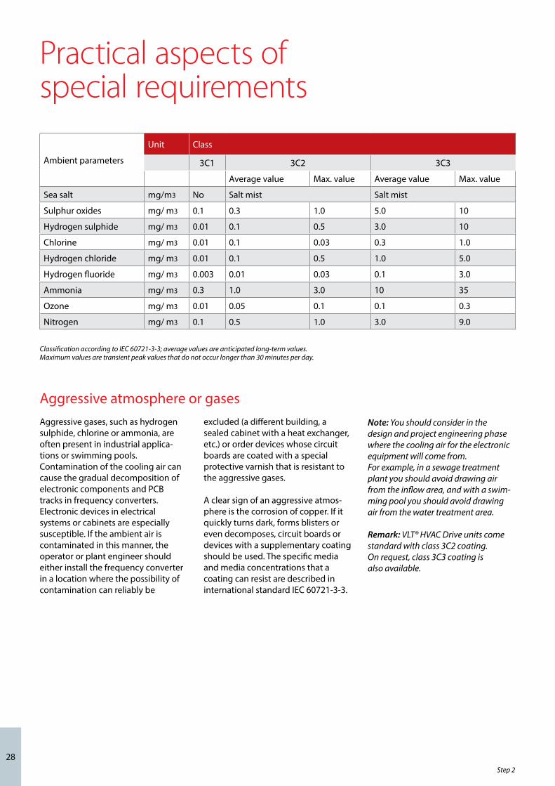
Aggressive gases, such as hydrogen sulphide, chlorine or ammonia, are often present in industrial applica-tions or swimming pools. Contamination of the cooling air can cause the gradual decomposition of electronic components and PCB tracks in frequency converters. Electronic devices in electrical systems or cabinets are especially susceptible. If the ambient air is contaminated in this manner, the operator or plant engineer should either install the frequency converter in a location where the possibility of contamination can reliably be
Classification according to IEC 60721-3-3; average values are anticipated long-term values. Maximum values are transient peak values that do not occur longer than 30 minutes per day.
excluded (a different building, a sealed cabinet with a heat exchanger, etc.) or order devices whose circuit boards are coated with a special protective varnish that is resistant to the aggressive gases.
A clear sign of an aggressive atmos-phere is the corrosion of copper. If it quickly turns dark, forms blisters or even decomposes, circuit boards or devices with a supplementary coating should be used. The specific media and media concentrations that a coating can resist are described in international standard IEC 60721-3-3.
Aggressive atmosphere or gasesNote: You should consider in the design and project engineering phase where the cooling air for the electronic equipment will come from.For example, in a sewage treatment plant you should avoid drawing air from the inflow area, and with a swim-ming pool you should avoid drawing air from the water treatment area.
Remark: VLT® HVAC Drive units come standard with class 3C2 coating. On request, class 3C3 coating is also available.
Practical aspects of special requirements
Step 2
Ambient parameters
Unit Class
3C1 3C2 3C3
Average value Max. value Average value Max. value
Sea salt mg/m3 No Salt mist Salt mist
Sulphur oxides mg/ m3 0.1 0.3 1.0 5.0 10
Hydrogen sulphide mg/ m3 0.01 0.1 0.5 3.0 10
Chlorine mg/ m3 0.01 0.1 0.03 0.3 1.0
Hydrogen chloride mg/ m3 0.01 0.1 0.5 1.0 5.0
Hydrogen fluoride mg/ m3 0.003 0.01 0.03 0.1 3.0
Ammonia mg/ m3 0.3 1.0 3.0 10 35
Ozone mg/ m3 0.01 0.05 0.1 0.1 0.3
Nitrogen mg/ m3 0.1 0.5 1.0 3.0 9.0

29
Installation of frequency converters in environments with high dust expo-sure is often unavoidable in practice. This dust forms deposits everywhere and penetrates into even the smallest cracks. This affects not only locally mounted frequency converters (wall or frame mount) with IP55 or IP66 protection rating, but also cabinet-mounted devices with IP21 or IP20 protection rating.The three aspects described below must be taken into account when frequency converters are installed in such environments.
Reduced coolingThe dust forms deposits on the surface of the device and inside the device on the circuit boards and the electronic components. These depos-its act as insulation layers and hamper heat transfer from the components to the ambient air. This reduces the
cooling capacity. The components be-come warmer. This causes accelerated aging of the electronic components, and the service life of the affected frequency converter decreases. The same thing happens when dust deposits form on the heat sink on the back of the frequency converter.
Cooling fansThe air flow for cooling frequency converters is produced by cooling fans, which are usually located on the back of the device. The fan rotors have small bearings into which dust penetrates and acts as an abrasive. This leads to fan failure due to bearing damage.
Filter matsHigh-power frequency converters in particular are equipped with cooling fans that expel hot air from the inte-rior of the device. Above a certain size, these fans are fitted with filter mats
that prevent the entry of dust into the device. These filter mats quickly be-come clogged when they are used in very dusty environments, and the fans are no longer able to cool adequately the components inside the frequency converter.
Dust exposure
Note: Under the conditions described above, it is advisable to clean the frequency converter during periodic maintenance. Blow the dust off the heat sink and fans and clean the filter mats.

30
Drive systems often operate in potentially explosive atmospheres. One example is the inflow area of a sewage treatment plant. If frequency converters are used for speed control of drives in such areas, the facility must fulfil special conditions. The basis for this is provided by EU Directive 94/9/EC, which is called the ATEX directive. It describes the use and operation of equipment and protective devices in potentially explosive atmospheres. This directive harmonises regulations and require-ments throughout the EU for the operation of electrical and electronic devices in potentially explosive atmospheres, such as may be caused by dust or gases.
If frequency converters are used to control motors in potentially explo-sive atmospheres, these motors must be equipped with temperature monitoring using a PTC temperature sensor. Motors with ignition protec-tion class “d” or “e” may be used. Theseignition protection classes differ in terms of how the ignition of an explosive medium is prevented. In practice, frequency converters are rarely used with “e” class motors. This combination must be approved as an unit, which involves elaborate and expensive type testing. However, the PTB in Braunschweig (Germany) has developed a new approval procedure that will make the use of speed
controllers with class “e” motors considerably more attractive in the future. The new concept calls for the acceptance of only the motor itself, while additionally defining specific requirements for thermal monitoring in the EC type test certification process. For instance, speed-depend-ent current limiting is required in addition to the usual certified PTC thermistor monitoring, in order to deal with the reduced cooling of self-ventilated motors with variable speed control.
Although this does not require separate approval of class “d” motors, feeding cables into the “d” area is very complicated. Motors with protection class “de” are the most widely used. In this case the motor itself has a “d” ignition protection class, while the connection space is implemented in compliance with the “e” ignition protection class. The restriction on the “e” connection space consists of the maximum voltage that may be fed into this space. Due to pulse-width modulation of the output voltage, most frequency converter outputs have peak voltages that exceed the allowable limits of class “e” ignition protection. In practice, using a sine-wave filter at the frequency converter output has proven to be an effective way to attenuate the high peak voltages.
Potentially explosive atmospheres
Code no of official instituteConformance mark
Temperature classExplosion groupProtection principleEquipment category
Equipment group
Ex d: Flameproof protection
Ex e: Increased safety
With ignition protection class “d”, the device is designed to ensure that if a spark occurs in a protected area (such as inside an enclosure),it cannot leave the protected area.
With ignition protection class “e”, the protection consists of preventing the occur-rence of sufficient energy to cause sparking.
Labelling of devices for operation in potentially explosive atmospheres in accordance with the ATEX product directive (94/9/EC)
Practical aspects of potentially explosive atmospheres
Note: Never install a frequency converter directly in an area with a potentially explosive atmosphere. It must be installed in a cabinet outside this area. Using a sine-wave filter at the output of the frequency converter is also recommended because it attenu-ates the voltage rate of rise du/dt and the peak voltage Upeak. The connected motor cable should be kept as short as possible due to the voltage drop in the cable.
Remark: Danfoss VLT® HVAC Drive frequency converters with the MCB 112 option have PTB-certified motor thermistor sensor monitor-ing capability for potentially explosive atmospheres. Shielded motor cables are not necessary when VLT® frequency converters are operated with sine-wave output filters.
Step 2

31
Mandatory minimum efficienciesEfficiency classification arose in 1998 as a result of a voluntary commit-ment by the European Committee of Manufacturers of Electrical Machines and Power Electronics (CEMEP)Starting in the summer of 2011, three-phase asynchronous motors are subject to mandatory minimum efficiency per-formance standards (MEPS) in the EU. EU regulations provide for increasingly strict motor efficiency requirements in a staged process extending to 2017.
The basis for these minimum efficien-cy classes, which are also called mini-mum energy performance standards (MEPS), is formed by the International Efficiency (IE) classes defined in IEC 60034-30, which are internationally
Efficiency classes IE1–IE3 are defined in international standard IEC 60034-30. The eff classes are based on a voluntary agreement between the EU and the CEMEP in 1998.
recognised. The limits of these classes are in part comparable to those of the eff classes widely used in Europe.
IE and eff classes: major differences in detailsAlthough the limits of the two standards are comparable, they differ in the underlying methods for determining efficiency. The effi-ciency of the eff classes is based on the determination of individual losses (IEC 60034-2:1996), a method that dates back 100 years. By contrast, the efficiency of the IE classes is determined using a more precise method.
The measured results obtained using the accepted method for the IE classes are usually 2 to 3% worse than
Affected three-phase motorsCompliance with the MEPS is manda-tory for the following types of three-phase motors:– Duty cycle S1 (continuous duty) or
S3 (intermittent periodic duty) with a duty cycle greater than 80%
– Pole count 2 to 6 Rated power 0.75 to 375 kW
– Rated voltage up to 1000 V.
Introduction of the MEPS is intended to help reduce energy consumption. However, in rare cases this approach can result in increased energy consumption. For this reason, EU Ordinance 640/2009 describes techni-cally reasonable exceptions for vari-ous application areas.
Step 3: Practical aspects of motors and cabling
with the old method at power levels up to 10 kW and around 1% worse at power levels of 100 kW and above. The standard takes these differences into account for the harmonisation of the IE and eff classes.
In addition to the IE1 to IE3 classes defined by the IEC 60034-30 standard, the draft version of IEC 60034-31 defines a new class: IE4. Classes IE1 to IE3 are primarily oriented towards mains-operated motors, while IE4 also takes aspects relevant to variable-speed motors into account. IE4 is presently not mandatory; it is used at present only for comparison with other efficiency classes.
They include:– Motors in potentially explosive atmospheres (as mentioned in
Directive 94/9/EC) and brake motors
– Special motors for use under any of the following operating conditions:
– ambient temperatures above 40 °C;
– ambient temperatures below 15 °C (0 °C for air-cooled motors); operating temperatures above 400 °C; cooling water tempera-tures below 5 °C or above 25 °C;
– operation at elevations above 1000 m;
– motors fully integrated in a product, such as geared motors, pumps or fans, or which (e.g. submersible pumps) are fully surrounded by a fluid medium in operation.
Within Europe, the motor of a geared motor is not regarded as an integral constituent and is measured seper-ately. A similar method is used with special motors. The base motor is measured, and the efficiency class is transferred to the motor variants.
Minimum efficiency performance classes for motors
IEC 60034-30 eff classes
IE1 (Standard Efficiency) Comparable to eff2
IE2 (High Efficiency) Comparable to eff1
IE3 (Premium Efficiency) Approximately 15–20% better than IE2

32
Practical aspects of IE classification of motorsSchedule forMEPS implementationThe schedule in the EU ordinance provides for a staged increase in motor efficiency requirements. After the scheduled dates, all three-phase motors subject to the ordinance must fulfil the requirements of the speci-fied efficiency class if they are to be marketed in Europe.
0 €
500 €
1.000 €
1.500 €
2.000 €
2.500 €
3.000 €
3.500 €
4.000 €
4.500 €
0,75 kW 1,1 kW 1,5 kW 2,2 kW 3 kW 4 kW 5,5 kW 7,5 kW 11 kW 15 kW 18,5 kW
IE4 to IE3 IE3 to IE2 IE2 to IE1
Energy cost advantage of an IE motor relative to the next IE class
Note: The full text of EU Regulation 640/2009 can be downloaded free of charge from the www.eur-lex.europa.eu website.
IE2 motors powered by converters are also accepted as an MEPS alternative to the planned IE3 class. Compliance
with class IE3 or the alternative of IE2 with a converter must be ensured at the operating site.
Cost-effectivenessA justified question with regard to the introduction of IE motors is: how cost-effective are they? The higher efficiency is in part achieved by employ-ing a higher proportion of active materials in the motors. Depending on the motor size, you can assume that a motor with a better efficiency class costs approximately 10 to 20% more.
In practice, this additional cost can often be recovered quickly. The chart shows the energy cost advantage of an IE motor compared to an IE motor in the next class. This simplified analysis is based on continuous operation at the rated load, 60,000 operating hours, and an electricity price of 8 Euro cents per kilowatt-hour.
Compliance with EN 50347 mounting dimension specificationsSynchronous three-phase motors conforming to classes IE2 and IE3 are often larger than motors with lower efficiency. This can lead to problems in the replacement of older motors.
Most IE2 motors conform to the shaft heights and fixing dimensions
standardised by EN 50347, but the construction form is often longer. In many cases, small 50-Hz IE3 Premium Class motors will not conform to the
EN 50347 mounting dimensions. Facil-ity operators should take heed of this in their motor replacement schemes.Alternative to IE3: IE2 plus converter.
Step 3
Power MEPS MEPS alternative
Starting 16 June 2011 0.75 – 375 kW IE2 -
Starting 1 January 20150.75 – 7.5 kW IE2 -t
7.5 – 375 kW IE3 IE2 with converter
Starting 1 January 2017 0.75 – 375 kW IE3 IE2 with converterSchedule for MEPS implementation
It is currently expected that class IE2 and IE3 synchronous three-phase motors will not be able to conform to the mounting dimensions defined in EN 50347.
Motor
IE1 IE2 IE3
Shaft height (EN 50347) Yes Yes Larger
Fixing dimensions (EN 50347) Yes Yes Larger
Motor length Yes Longer Larger

33
Practical aspects of EC and PM motorsWhat are EC motors ? In the HVAC market, the term ´EC motor´ is commonly understood to mean a specific type of motor, which many users associate with compact construction and high efficiency. EC motors are based on the idea of using electronic commutation (EC) instead of conventional carbon brush commutation for DC motors.
For this purpose, manufacturers of these motors replace the rotor winding with permanent magnets and incorporate commutation circuitry. The magnets boost the efficiency, whilst electronic commu-tation eliminates the mechanical wear of carbon brushes. As the operating principle is based on that of a DC motor, EC motors are also called Brush Less DC (BLDC) motors.
These motors are generally used in low power ranges of a few hundred watts. Motors of this type used for applications in the HVAC sector are typical motors in outer rotor design and cover a limited power range,
presently extending to approximately 6 kW.
Efficiency of EC motorsSplit-pole motors and single-phase asynchronous motors have poor efficiency in the power range of a few hundred watts. The idea that EC motors have an enormous efficiency advantage is also based on compari-son with these motors. If the efficien-cies of EC motors are compared with the typical efficiencies of three-phase asynchronous motors, this advantage decreases rapidly with increasing power.
PM motors – an alternative to EC?Permanent magnet (PM) motors provide an alternative to EC motors, with efficiencies comparable to those of EC motors. They additionally have the advantage relative to EC motors that they are available in a consider-ably larger power range. PM motors are driven using essentially the same method as that used for three-phase asynchronous motors. PM
PMAC Synchronous motors
BLDC - Brushless DC motor
Also known as EC motor or EC technology
IPMSM Embedded magnets
PMSM Sinusoidal commutation
SPMSM Surface mounted
magnets
Usual motor designation: PM motors
PMAC = Permanent Magnet AC; BLDC = Brushless DC; PMSM = Permanent Magnet Synchronous Motor; IPMSM = Interior PMSM (embedded magnets); SPMSM = Surface PMSM (magnets mounted on rotor)
motors, which for this reason are in general classified as AC motors, are available in various forms, including servo motors and motors with the same IEC dimensions as standard three-phase asynchronous motors.
One of the main differences between PM and EC motors is the supply voltage. As suggested by the different classifications (DC versus AC motors), EC motors have square-wave commu-tation while PM motors use sinusoidal commutation. A common feature of both types of motor is that they need control electronics.
The overall efficiencies of both systems (motor and electronics) are compara-ble for systems with similar configura-tions (mains supply, EMC filter, etc.). However, EC motors have higher torque ripple as a result of square-wave commutation and higher iron losses. In addition, as a result of square-wave commutation their current consumption (distributed over two phases instead of three) is 1.22 times that of PM motors.
Note: The characteristics of single-phase motors are often compared with the characteristics of three-phase motors in discussions of EC motors. Example: Single-phase EC motors are usually equipped with power factor correction (PFC) to achieve a power factor close to 1, but a three-phase converter does not need PFC for this. Accordingly, users should determine what the technical specifications are based on.

34
Practical aspects of EC and PM motors
The Danfoss EC+ concept allows PM motors to be used with Danfoss VLT® frequency converters. Danfoss has integrated the necessary control algorithm in the existing VLT® converter series. This means that there are no changes for the operator. After entering the relevant motor data, the user benefits from the high motor efficiency of EC technology.
Advantages of the EC+ conceptn Free choice of motor
technology: PM or asynchronous with the same frequency converter
n Device installation and operation remain unchanged
n Manufacturer independence in the choice of all components
n Superior system efficiency thanks to a combination of individual components with optimum efficiency
n Retrofitting of existing systems possible
n Wide range of rated powers for standard and PM motors
Basic comparison of EC and PM motors
Does the best motor efficiency yield the best system efficiency?What is the benefit of a high-efficiency motor design if the installed bearings reduce motor efficiency ? This principle also applies to the overall system, since optimal system efficiency is the key to reducing energy consumption and thereby reducing costs.
System efficiency is calculated according to VDI DIN 6014 by multiplying the efficiencies of the components:
η system = η converter x η motor x η coupling x η fan
ηDrive
= 89%
ηFan
= 68%
ηSystem
= 60%
ηDrive
= 83%
ηFan
= 75%
ηSystem
= 63%
ηDrive
= 89%
ηFan
= 75%
ηSystem
= 66%
EC motor + integrated electronics + fan
Induction motor + VSD + direct drive fan
PM/EC motor + VSD + direct drive fan
The stated drive efficiencies (converter x motor) are based on measurements, while the fan efficiencies are taken from manufacturer catalogues. Due to the directly driven fan, ηcoupling = 1
Example efficiency calculation for a drive system with a 450-mm radial fan
ηDrive
= 89%
ηFan
= 68%
ηSystem
= 60%
ηDrive
= 83%
ηFan
= 75%
ηSystem
= 63%
ηDrive
= 89%
ηFan
= 75%
ηSystem
= 66%
For example, if a fan with low efficiency is driven by a high-efficiency motor, the end result is an average efficiency level. Radial fans with EC motors are a good practical example. To achieve very compact construction, manufacturers often use the EC motor as the hub of the impeller. However, such a large hub signifi-cantly reduces the efficiency of the fan and thus the efficiency of the overall system.
34Step 3
Motor electronics
Motor construction
Power range Commutation
EC Simple Complex up to approx. 6 kW Square-wave (DC)
PM Complex Simple up to MW range Sinusoidal (AC)

35
Selection criteria The following aspects must be taken into consideration in connection with motors controlled by frequency converters:– Insulation stress– Bearing stress– Thermal stress
Insulation stressOperating a motor with frequency control imposes higher stress on the motor winding than direct mains operation This is primarily due to the steep pulse edges (du/dt) and the motor cable, depending on cable length, type, routing, etc.
The steep pulse edges result from the rapidly switching semiconductor devices in the inverter stage of the frequency converter. They operate at a high switching frequency in the range of 2 to 20 kHz with very short switching times in order to reproduce a sinusoidal waveform.
In combination with the motor cable, these steep pulse edges are responsible for the following effects at the motor:– High pulse voltages ULL on the motor terminals put additional stress on the interwinding insulation
– Higher pulse voltages between the windings and the laminations ÛLE put additional stress on the slot insulation– Higher voltages between the win dings Ûwdg put significantly higher stress on the insulation of the wire in the windings.
Bearing stressUnder unfavourable conditions, frequency-controlled motors may fail due to bearing damage caused by bearing currents. Current flows in a bearing when the voltage across the bearing lubrication gap is high enough to penetrate the insulation layer formed by the lubricant. If this happens, imminent failure of the bearing is signalled by increasingly louder bearing noise. Bearing currents of this sort include high-frequency eddy currents, earth currents and EMD currents (spark erosion).
Which of these currents may lead to bearing damage depends on the following factors: – The mains voltage at input of the frequency converter – The steepness of the pulse edges (du/dt) – The type of motor cable
1. 2. Coil
ULE
ULL
U
V
WUWdg
Pulse voltages appear in the motor at the motor terminals (ULL) and between the windings and the lamination stack (ULE). There is also a voltage stress between the windings (Uwdg).
Note: Bearing currents result from the action of the entire system, consisting of the frequency converter, motor, cable and earthing. IEC 60034-17 recommends taking preventive measures at shaft heights of 315 mm (approx. 132 kW) and above.
Note: Request confirmation from the motor manufacturer that the motor is designed for operation with a fre-quency converter and confirmation of the allowable operating speed range (minimum and maximum rpm).
– Electrical shielding– System earthing– Motor size– The earthing system of the motor housing and the motor shaft.
Bearing currents can be reduced by the following measures:– Fitting output filters (output chokes,
du/dt filters, or sine-wave filters)– Fitting electrically insulated
bearings– Good earthing of all metallic system
components with low-impedance connections
– Shielded motor cables– Fitting a DC suppression filter.
Thermal stressOperation with a frequency converter increases the power dissipation in the motor. The additional harmonic content causes iron losses and current heat losses in the stator and rotor. The magnitude of the losses depends on the amplitude and frequency of the harmonics of the drive frequency. The additional current heat losses in the rotor depend on the slot geometry. Iron losses and current heat losses in motors are not load-dependent. The additional losses in the motor cause higher thermal stress on the winding insulation. However, with modern frequency converters the additional heating of standard motors (up to frame size 315) is comparable to the additional warming due to mains voltage tolerances and is therefore negligible. Manufacturers sometime specify a derating factor for trans-standard motors (frame size 355 and above).
If the converter is not able to gener-ate the full mains voltage at the rated mains frequency, it is advisable to select a motor with Class F insulation. Operating a motor at a voltage lower than with direct mains operation increases the motor temperature by up to 10 K.
Practical aspects of motor suitabilityfor frequency converter operation
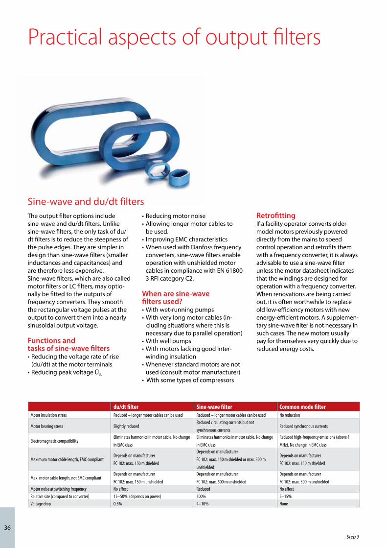
36
The output filter options include sine-wave and du/dt filters. Unlike sine-wave filters, the only task of du/dt filters is to reduce the steepness of the pulse edges. They are simpler in design than sine-wave filters (smaller inductances and capacitances) and are therefore less expensive.Sine-wave filters, which are also called motor filters or LC filters, may optio-nally be fitted to the outputs of frequency converters. They smooth the rectangular voltage pulses at the output to convert them into a nearly sinusoidal output voltage.
Functions and tasks of sine-wave filters• Reducing the voltage rate of rise (du/dt) at the motor terminals• Reducing peak voltage ÛLL
• Reducing motor noise• Allowing longer motor cables to be used. • Improving EMC characteristics• When used with Danfoss frequency converters, sine-wave filters enable operation with unshielded motor cables in compliance with EN 61800- 3 RFI category C2.
When are sine-wave filters used?• With wet-running pumps• With very long motor cables (in- cluding situations where this is necessary due to parallel operation)• With well pumps• With motors lacking good inter- winding insulation• Whenever standard motors are not used (consult motor manufacturer)• With some types of compressors
RetrofittingIf a facility operator converts older-model motors previously powered directly from the mains to speed control operation and retrofits them with a frequency converter, it is always advisable to use a sine-wave filter unless the motor datasheet indicates that the windings are designed for operation with a frequency converter.When renovations are being carried out, it is often worthwhile to replace old low-efficiency motors with new energy-efficient motors. A supplemen-tary sine-wave filter is not necessary in such cases. The new motors usually pay for themselves very quickly due to reduced energy costs.
Practical aspects of output filters
Sine-wave and du/dt filters
Step 3
du/dt filter Sine-wave filter Common mode filterMotor insulation stress Reduced – longer motor cables can be used Reduced – longer motor cables can be used No reduction
Motor bearing stress Slightly reducedReduced circulating currents but not
synchronous currentsReduced synchronous currents
Electromagnetic compatibilityEliminates harmonics in motor cable. No change
in EMC class
Eliminates harmonics in motor cable. No change
in EMC class
Reduced high-frequency emissions (above 1
MHz). No change in EMC class
Maximum motor cable length, EMC compliantDepends on manufacturer
FC 102: max. 150 m shielded
Depends on manufacturer
FC 102: max. 150 m shielded or max. 300 m
unshielded
Depends on manufacturer
FC 102: max. 150 m shielded
Max. motor cable length, not EMC compliantDepends on manufacturer
FC 102: max. 150 m unshielded
Depends on manufacturer
FC 102: max. 500 m unshielded
Depends on manufacturer
FC 102: max. 300 m unshieldedMotor noise at switching frequency No effect Reduced No effectRelative size (compared to converter) 15–50% (depends on power) 100% 5–15%Voltage drop 0.5% 4–10% None

37
Rated voltagePeak voltages up to three times the DC link voltage in the frequency converter occur in the motor cable. They severely stress the motor cable and the motor insulation. The stress is higher if the frequency converter output does not have a du/dt filter or sine-wave filter.
For this reason, the rated voltage specification of the motor cables should be at least U0/U = 0.6/1 kV. High-voltage insulation testing of cables with this specification is usually performed with a test voltage of at least 3,500 V AC and usually 4,000 V AC, and in practice they have proven to have good resistance to insulation breakdown.
Cable dimensioningThe required cross-section of the motor cable depends on the output current of the frequency converter, the ambient temperature, and the type of cable installation. Overdimen-sioning the wire cross-section to allow for harmonics is not necessary.
For the selection and dimensioning of cables and conductors, EN 60204-1 and VDE 0113-1 provide current capacity data for wire cross-sections up to 120 mm². If larger wire cross-sections are necessary, useful infor-mation can be found in VDE 0298-4.
Motor cable lengthIn installations with long motor cables the voltage drop over the cable must be taken into account in cable dimensioning.
Design the system so the full output voltage reaches the motor, even with a long motor cable. The length of the motor cable that can be connected to a standard frequency converter is typically 50 to 100 metres. Even with these cable lengths, products from some manufacturers cannot provide the full output voltage at the motor.
If users need cables longer than 100 m, there are only a few manufacturers that can meet this requirement with standard products. Otherwise it is necessary to provide supplementary motor chokes or output filters.
Energy savingsThe voltage drop over a motor cable, as well as the resulting heat dissipa-tion, is nearly proportional to its length and dependent on the frequency.
Accordingly, you should keep cable runs as short as possible and dimen-sion the wire cross-sections no larger than is electrically necessary.
Practical aspects of motor cables
Note: Consult the manufacturer regarding the lengths of cables that may be connected to the frequency converter and the expected voltage drop.With a standard VLT® HVAC Drive frequency converter, you can connect a shielded cable up to 150 m long or an unshielded cable up to 300 m long and still have the full voltage at the motor.
Installation method B1: Conduc-tors in conduit or closed wiring ducts
Installation method B2: Multi-conductor cable or multicon-ductor sheathed cable in conduit or closed wiring ducts
Installation method C: Direct installation on or in walls and/or ceilings or in cable trays
Installation method E - Installation frei in Luft, an Tragseilen sowie auf Kabelpritschen und -konsolen
Cables with suitable shieldingShielded cables should have a shield coverage of at least 80%. Some examples of suitable cable types are:– Lapp Ölflex 100-CY– Helu Y-CY-JB– Helu Topflex-EMV-UV-2YSLCYK-J
Installation method B1: Conduc-tors in conduit or closed wiring ducts
Installation method B2: Multi-conductor cable or multicon-ductor sheathed cable in conduit or closed wiring ducts
Installation method C: Direct installation on or in walls and/or ceilings or in cable trays
Installation method E - Installation frei in Luft, an Tragseilen sowie auf Kabelpritschen und -konsolen
Installation method B1: Conductors in conduit or closed wiring ducts
Installation method B1: Conduc-tors in conduit or closed wiring ducts
Installation method B2: Multi-conductor cable or multicon-ductor sheathed cable in conduit or closed wiring ducts
Installation method C: Direct installation on or in walls and/or ceilings or in cable trays
Installation method E - Installation frei in Luft, an Tragseilen sowie auf Kabelpritschen und -konsolen
Installation method B2: Multiconductor cable or multiconductor sheathed cable in conduit or closed wiring ducts
Installation method C: Direct installation on or in walls and/or ceilings or in cable trays
Installation method E: Installation in open air and in cable trays
Current rating [A] of PVC cable at 40°C ambient temperature
mm² B1 B2 C E
1 10,3 10,1 11,7 12,4
1,5 13,5 13,1 15,2 16,1
2 18,3 17,4 21,0 22,0
4 24,0 23,0 28,0 30,0
6 31 30,0 36,0 37,0
10 44,0 40,0 50,0 52,0
16 59,0 54,0 66,0 70,0
25 77,0 70,0 84,0 88,0

38
Star-configured earthing systemAll earthed points and components must be connected to the central earthing point as directly as possible, such as by means of a potential equali-sation rail. This results in an earthing system in which all connection points are connected radially to the earth-ing point. This earthing point must be defined unambiguously.
Contact pointsAfter paint and corrosion have been removed, connections must be made to contact points using a large surface area. Serrated washers are better for this purpose than plain washers. Tin-plated, zinc-plated or cadmium-plated components should be used in preference to painted components. Multiple contacts for the shield con-nection must be provided in connec-tors.
Conductor surface areaA large conductor surface area for draining high-frequency currents can be obtained by using fine stranded
wire, such as high-flexibility instru-ment wire, or by using special earth-ing straps or cables. Braided earthing straps are often used nowadays in practice; they replace the rigid con-ductors used in the past. These straps have a significantly higher surface area with the same cross-section.
Earthing measures are generally imperative in order to fulfil the statutory requirements of the EMC and Low Voltage directives. They are a prerequisite for the effective use of other measures, such as shielding and filters. Other measures are of no benefit without good earthing. For this reason, the earthing arrangements must be checked and verified for proper EMC implementation before retrofitting shielding or filters and as the first step in troubleshooting.
Electrically conductive materialsOperators must ensure that metallic surfaces are earthed with low-imped-ance connections. In terms of EMC, the decisive factor is not the cross-section of the conductor but instead its surface area, since high-frequency currents flow on the surface due to the skin effect. The portion with the smallest conductor surface area is what limits the ability to drain leakage currents. Earthed surfaces have a shielding effect and reduce the amplitude of ambient electromagnetic fields.
Frequency converter
Output lter
To avoid disturbance do not use facility earthing
Protective earth outdoor conductor
PE
Facility earthing
An earthing plan should always be generated for every system or facility.
The importance of earthing
Note: System earthing has a substan-tial effect on smooth, trouble-free facility operation. Ground loops must be avoided. Good potential equalisa-tion is essential. Generate a suitable earthing plan as early as the design and projecting engineering stage.
Practical aspects of earthing
Step 3

39
The purpose of shielding is to reduce the magnitude of radiated interfer-ence (which may affect adjacent systems or components) and to improve the interference immunity of individual devices (immunity to interference from external sources).
Implementation of shielding meas-ures in existing systems (e.g. cable replacement or additional enclosures) is possible only at considerable expense. Manufacturers of frequency converters usually provide suitable information regarding compliance with statutory limits, which also includes information on additional measures that may be necessary, such as shielded cables.
Frequency converters generate steep-edged pulses on their outputs. These pulses contain high-frequency components (extending into the gigahertz range), which cause undesirable radiation from the motor cable. This is why shielded motor cables must be used. The task of the shield is to “capture” the high-fre-
quency components and conduct them back to the interference source, in this case the frequency converter.
Shielded cables and wiringEven good shielding that complies with the limits does not fully eliminate the radiation. In the near-field region, you can expect to find electromag-netic fields that components and system modules located in this environment must be able to with-stand without any degradation of their operation. Here the standard requires conformance to the limits at a speci-fied distance (e.g. 30 dB at a distance of 10 m for Class B). With regard to the level of the allowable limit, the standard distinguishes between use in 1st environment (residential environ-ment) and 2nd environment (industrial environment). For detailed informa-tion, see “The operating site is the decisive factor” section of this manual on page 22.
Shield connectionThe cable shield must be connected all the way around to achieve effective
cable shielding. EMC (earthing) cable glands or earthing cable clamps can be used for this purpose. They fully surround the shield and connect it to ground over a large area. The shield must be routed directly to the earthing point and clamped firmly over a large area and the connection should be kept as short as possible at each end of the cable. All other connection methods degrade the effectiveness of the shield. Users often twist the shield braid into a pigtail and use a clamping terminal to connect it to ground. This form of connection creates a high transfer impedance for high-frequency signal components, which causes interference to be radiated from the shield instead of being fed back to the source. As a result, the shielding effect may be reduced by as much as 90%.
Shield gapsShield gaps such as terminals, switches or contactors must be bridged by connections with the lowest possible impedance and the largest possible surface area.
Wrong Correct
Wrong Correct
The importance of shielding
Practical aspects of shielding
DDC
Remove cable isolation
Earthing strip
Output relais
DDC etc. Enclosure plate
Min. 10mm²
Min. 10mm²
PE Min. 10mm²
Motor
Compensation cable
Control cables
Mains supply
L1L2L3PE
Motor cable
All cables mounted on one plate side
Min. 200mm between control cables, motor cables and signal cables
Frequency converter

40
Ground connectionThe ground connection of a shield is crucial for its effectiveness. For this reason, serrated washers or split washers must be fitted under enclosure assembly screws and painted surfaces must be scraped clean in order to obtain a low-impedance contact. Anodised aluminium enclosures, for example, provide inadequate ground bonding if plain washers are used under the fastening screws. Earth and ground leads should be made from wire with a large cross-section, or better yet from multi-cored grounding wire. If wire cross-sections less than 10 mm² are used with low-power motors, a separate PE line with a cross-section of at least 10 mm² must be run from the converter to the motor.
Motor supply cableIn order to comply with radio fre-quency interference limits, cables between frequency converters and motors must be shielded cables with the shield connected to the equip-ment at both ends.
Signal cableThe distance between the motor cable and the signal cable should be more than 20 cm, and the mains cable and motor cable should be routed separately as much as possible. Interference effects decrease signifi-cantly with increasing distance. Additional measures (such as divider strips) are essential with smaller separations. Otherwise interference may be coupled in or transferred.Control cable shields must be con-nected at both ends in the same way as motor cable shields. In practice, sin-gle-ended grounding may be consid-ered in exceptional cases. However, it is not recommended.
Types of shieldsFrequency converter manufacturers recommend using shielded cable to shield the wiring between the frequency converter and the motor. Two factors are important for selec-tion: the shield coverage and the type of shielding.
The shield coverage, which means the amount of cable surface covered by the shield, should be at least 80%.With regard to the shield type, a single-layer braided copper shield has proven to be extremely effective in practice. Here it is important that the shield is braided. By contrast, a wound copper wire shield (such as type NYCWY) leaves long slit-shaped areas uncovered, and HF components can easily escape through these gaps. The surface area for leakage currents is also significantly smaller.
Shielding is available in bulk for retrofitting. It can be pulled over the cable to provide the desired shielding effect. For short connections, metal hoses or pipes can be used as an alternative. Cable ducts can replace shielding only under certain conditions (a radiation-proof duct with good cover contact and a good connection between the duct components and ground).
Cables with double shielding further improve the attenuation of emitted and radiated interference. The inner shield is connected at one end, while the outer shield is connected at both ends. Twisted conductors reduce magnetic fields.
Shielded cables with twisted conduc-tors can be used for signal lines. The attenuation of the magnetic field increases from around 30 dB with a single shield to 60 dB with a double shield and to approximately 75 dB if the conductors are also twisted.
Practical aspects of shielding
Transfer impedance, ZtmΩ/m105
104
103
102
10
1
0,01 0,1 1 10 100 MHz
10-1
10-2
10-3
Aluminum coated with copper wire
Spiral copper wire or reinforced steel cable
Copper wire, single-layer, braided with percental varying screen coverage
Copper wire double-layer, braided with magnetic screened interlayer
Cable inside copper or steel tube
Copper wire double-layer, braided
There are many types of shielded cable. Only some of them are suitable for use with frequency converters.
Step 3

41
Basic designIn practice, designers and operators often select frequency converters solely on the basis of their rated power in kilowatts. However, frequency converters must always be selected on the basis of the actual rated motor current Inom under the highest system load. This selection criterion is more reliable because motor output power depends on the mechanical shaft load instead of the electrical input power. The motor efficiency is also not taken into account. By contrast, the rated capacity of frequency converters (in kilowatts) is based on the rated power Pnom of four-pole motors.In addition, motors in the same power class may have different rated currents, depending on the motor manufacturer and the efficiency class. For example, the rated current of an 11-kW motor can range from 19.8 A to 22.5 A.
However, the rated current alone is not sufficient to determine the correspon-ding electrical input power. The frequency converter must also supply a sufficiently high motor voltage. With a 400 V mains system, this means a full 400 V at 50 Hz on the motor terminals. There are still frequency converters on the market that are not able to achieve this. The output voltage is reduced due to voltage drops in the filters, chokes and motor cable. If the output voltage is reduced to 390 V, for example, the motor needs more current to produce the required power.
As the losses increase quadratically with the current, the motor heats up more, which reduces its service life. Of course, the user must also take the increased current demand into account in the design.
Constant or variable torqueThe load driven by the motor is the key factor for selecting the right frequency converter. A distinction must be made between loads whose torque charac-teristic increases quadratically with increasing speed (such as centrifugal pumps and fans) and loads that can require high torque from the motor over their entire working range, even at low speeds (such as Roots blowers).
Most drive systems in HVAC applica-tions have a load curve that increases quadratically with speed until the rated torque is reached. In order to achieve efficiency-optimised operation under these load conditions, the frequency converter provides a motor voltage that increases quadratically with the motor rotating field fre-quency.
For applications with a constant high torque, in most cases it is also neces-sary to consider the requirement for acceleration or start-up under heavy load. In this case, the frequency converter must be able to supply extra drive power to the motor for a short
Step 4: Practical aspects of frequency converter selection
Remark: An 11 kW VLT® HVAC Drive frequency converter has a rated current of 24 A. This provides enough reserve power to drive a motor rated at 11 kW.
Remark: A special modulation method is used in VLT® HVAC Drive units to provide the full motor voltage. Even with 10% under-voltage on the mains, the rated motor voltage and rated motor torque are maintained.
Note: Displacement pumps, Roots blowers and compressors are not classified as fluid flow machines. Due to their operat-ing principle, frequency converters for use with such equipment should be designed for constant torque.
time, in addition to the rated motor torque, for example to enable a pump in which sludge has collected and deposited to overcome the resulting static friction. This briefly available maximum torque is called overload torque.
In applications that do not need start-up torque significantly higher than the rated motor torque, a relatively low overload capacity is generally adequate (for example, Roots blowers with unloaded start-up require only 110 % of the rated motor torque).

42
Characteristic curves and applicationsConstant-torque applicationsLow starting torque (110% overload)Scroll compressor [0.6 to 0.9 nominal] Screw compressor [0.4 to 0.7 nominal]Piston compressor [0.6 to 0.9 nominal]
Normal starting torque [overtorque]Scroll compressor [1.2 to 1.6 nominal] Screw compressor [1.0 to 1.6 nominal]cylinder compressor [up to 1.6 nominal]4-cylinder compressor [up to 1.2 nominal] 6-cylinder compressor [up to 1.2 nominal]
High starting torque [overtorque]2-cylinder compressor [up to 2.2 nominal]4-cylinder compressor [up to 1.8 nominal]6-cylinder compressor [up to 1.6 nominal]
Variable-torque applicationsFansCentrifugal pumpsWell pumps1
Pressure booster pumpsFilter feed pumpsGroundwater pumps1
Hot water pumpsHeating pumps (primary and secondary circuit)Ducted impeller pumps (solids)Cooling water pumps (primary and secondary circuit)Cistern pumpsSludge recirculation pumpsSump pumps1 TurbocompressorsSubmersed pumps1
Surplus sludge pumps1Sine-wave filter recommended
Note: Compressors usually have a limited speed range (min./max. speed or frequency) as well as a limited number of start/ stops and/or require a sinusoidal filter for operation. Remember to check the torque characteristics of pumps before using them.
Torq
ue
Fortsetzung nächste Seite
Anwendung mit konstantem Drehmoment in % 1)
Drehkolbengebläse 110
Oberflächenbelüfter 110
Dosierpumpen (Bürgerpumpen) 110
Druckerhöhungspumpen (mehrstufig) 110
Rezirkulationspumpen 110
Seitenkanalverdichter (für die Beckenbelüftung) 110
Verdrängerpumpe (Exenterschnecke für Schlammbeh.) 150
Verdichter 150
Drehkolbenverdichter 150
Axialkolbenverdichter 150
Beschickung von Schlammentwässerungspressen 150
Rührwerke 150
Zahnradpumpen 150
Kolbenpumpen 150
Zahnradschleusen 150
Anwendung mit quadratischem Drehmoment
Tauchmotorpumpen 2)
Unterwasserpumpen 2)
Brunnenpumpen 2)
Grundwasserpumpen 2)
Kreiselpumpen
Heisswasserpumpen
Primär- & Sekundär- Heizungspumpen
Primär- & Sekundär- Kühlwasserpumpen
Druckerhöhungspumpen (Kreiselpumpen)
Regenbeckenentleerungspumpen
Ventilatoren
Überschußschlammpumpen
Filterbeschickungspumpen
Rücklaufschlammpumpen
Kanalradpumpen (feste Stoffe)
DrehzahlabhängigeBelastungscharakteristik
DrehzahlunabhängigeBelastungscharakteristik
Quadratisches DrehmomentKonstantes Drehmoment
Drehzahl
Dre
hmo
men
t
Drehzahl
Dre
hmo
men
t
1) Überlast-Drehmoment in % (110% - normales Anlaufmoment / 150% - hohes Anlaufmoment)2) Wir empfehlen den Einsatz eines Sinusfilters, fragen Sie Sie bitte beim Pumpen-/Motorenhersteller nach.
Speed
Speed dependentload characteristics
Variable torque
Practical aspects of load curves for HVAC/R applications
Fortsetzung nächste Seite
Anwendung mit konstantem Drehmoment in % 1)
Drehkolbengebläse 110
Oberflächenbelüfter 110
Dosierpumpen (Bürgerpumpen) 110
Druckerhöhungspumpen (mehrstufig) 110
Rezirkulationspumpen 110
Seitenkanalverdichter (für die Beckenbelüftung) 110
Verdrängerpumpe (Exenterschnecke für Schlammbeh.) 150
Verdichter 150
Drehkolbenverdichter 150
Axialkolbenverdichter 150
Beschickung von Schlammentwässerungspressen 150
Rührwerke 150
Zahnradpumpen 150
Kolbenpumpen 150
Zahnradschleusen 150
Anwendung mit quadratischem Drehmoment
Tauchmotorpumpen 2)
Unterwasserpumpen 2)
Brunnenpumpen 2)
Grundwasserpumpen 2)
Kreiselpumpen
Heisswasserpumpen
Primär- & Sekundär- Heizungspumpen
Primär- & Sekundär- Kühlwasserpumpen
Druckerhöhungspumpen (Kreiselpumpen)
Regenbeckenentleerungspumpen
Ventilatoren
Überschußschlammpumpen
Filterbeschickungspumpen
Rücklaufschlammpumpen
Kanalradpumpen (feste Stoffe)
DrehzahlabhängigeBelastungscharakteristik
DrehzahlunabhängigeBelastungscharakteristik
Quadratisches DrehmomentKonstantes Drehmoment
Drehzahl
Dre
hmo
men
t
Drehzahl
Dre
hmo
men
t
1) Überlast-Drehmoment in % (110% - normales Anlaufmoment / 150% - hohes Anlaufmoment)2) Wir empfehlen den Einsatz eines Sinusfilters, fragen Sie Sie bitte beim Pumpen-/Motorenhersteller nach.
Constant torque
Speed independentload characteristics
Speed
Torq
ue
Step 4

43
DesignIf the operator’s objective is to run several motors in parallel from the same frequency converter, the following factors must be taken into account in the design:
The rated currents and powers of the motors must be added together.
Selection of a suitable frequency converter is based on the two sums power and current.For motor protection, the operator must connect the PTC thermistors of the motors in series, and the frequency converter will then monitor this series-connected signal.
M
MVSD
M
MVSD
M
M
M
VSDSinusFilter
Problematisch: Parallele Leitungen erzeugen zusätzliche Kapazitäten.Nur bei kurzen Kabeln zu empfehlen
Nach (Sinus) Filter sind parallele Leitungen unproblematisch
Ideal: Kabel von Motor zu Motor durch-schleifen
MM
M
MVSD
M
MVSD
M
M
M
VSDSinusFilter
Problematisch: Parallele Leitungen erzeugen zusätzliche Kapazitäten.Nur bei kurzen Kabeln zu empfehlen
Nach (Sinus) Filter sind parallele Leitungen unproblematisch
Ideal: Kabel von Motor zu Motor durch-schleifen
MM
M
MVSD
M
MVSD
M
M
M
VSDSinusFilter
Problematisch: Parallele Leitungen erzeugen zusätzliche Kapazitäten.Nur bei kurzen Kabeln zu empfehlen
Nach (Sinus) Filter sind parallele Leitungen unproblematisch
Ideal: Kabel von Motor zu Motor durch-schleifen
MM
Cable routing
To be avoided with multi-motor operation:Parallel conductors cause additional capacitance. For this reason, users should always avoid this type of connection.
The working currents drop because the LC filter blocks the clock frequency. This allows the motors to be connected in parallel. The motor cables may also be routed together over longer distances if necessary.
Recommended for multi-motor operation: daisy-chain the motor cable from one motor to the next.
To be avoided Recommended Recommended
Practical aspects of multi-motor operation (special case)
The connected motors operate the same in terms of their rated speed. This means that the frequency converter drives all of them at the same frequency and with the same voltage.
Note: Due to the fact that the resist-ances of the series-connected PTC thermistors add together, there is no point in using the thermistor monitor-ing capability of the frequency converter for motor protection if more than two motors are operated in parallel.

44
Practical recommendationsSee pages 21 ff of this manual for extensive information on radio frequency interference. The main objective in practice is to obtain systems that operate stably without interference between their components. Nevertheless, it often happens that after remodelling and/or the introduction of new components, it is no longer possible to make sensitive measurements without interference and/or the instrument signals are corrupted. These pitfalls are exactly what must be avoided.In order to achieve a high level of interference immunity, it is therefore advisable to use frequency converters with high-quality RFI filters. They should fulfil the category C1 require-ments specified in the EN 61800-3 product standard and thereby con-form to the Class B limits of the EN 55011 generic standard.
Additional warning notices must be placed on the frequency converter if RFI filters that do not correspond to category C1, but instead only category C2 or lower, are used. The responsibi-lity ultimately rests with the operator.As mentioned on page 22, in case of problems the inspection authority will always base its recommendations for eliminating interference on the A1/A2 and B limits for interference defined in the EN 55011 generic standard
according to the operating environ-ment. The operator bears the costs of remedying EMC problems. The operator is ultimately responsible for the appropriate classification of devices with respect to these two standards.
Due to the use of cables to transmit signals and power, conductive interference can easily spread to other parts of the system or facility if adequate measures are not taken. By contrast, interference radiated directly from the device or the cable is spatially confined. Its intensity decreases with every centimetre of distance away from the interference source. For this reason, installation of the converter in a suitable cabinet in compliance with EMC rules is usually sufficient to limit radiated interference. However, the system operator should always provide a suitable filter to limit conducted interference.
Two approaches to RFI filtersIn practice, there are two approaches to RFI filters. Some manufacturers install RFI filters in their equipment as standard, while other manufacturers offer them as options. Built-in filters not only save a lot of space in the cabinet, but also eliminate additional costs for fitting, wiring and material. However, the most important advantage is the perfect EMC
Note: To ensure interference-free operation of the drive system, you should always use a category C1 RFI filter. VLT® HVAC Drive units are supplied as standard with built-in RFI filters conforming to category C1 (EN 61800-3) for use with 400 V mains systems and power ratings up to 90 kW or category C2 for power ratings of 110 to 630 kW. VLT® HVAC Drive units conform to C1 (conducted emission) with shielded motor cables up to 50 m or C2 with shielded motor cables up to 150 m.
All frequency converters are wide-band interference sources, which means they emit interference over a wide frequency range. Facility operators can reduce the amount of interference emitted by frequency converters by taking suitable meas-ures. For example, they can ensure trouble-free facility operation by using RFI filters and mains chokes.
With some makes, these components are already installed in the frequency converter. With other makes, the plant engineer must allow additional space (which is always at a premium) for this in the cabinet. For general information regarding EMC, low-frequency mains interfer-ence and radio-frequency interfer-ence, see pages 13 ff of this manual.
Putting theory into practice
Radio frequency interference
Note: Good-quality frequency converters are equipped with good RFI protection and mains interference reduction components as standard. These components account for approximately 15 to 20% of the price of a frequency converter.
Practical aspects of EMC measures
conformance and cabling of inte-grated filters.Optional external RFI filters installed ahead of the frequency converter also cause an additional voltage drop. In practice, this means that the full mains voltage is not present at the frequency converter input and overdimensioning may be necessary. Costs are incurred for assembly, cabling and the material, and EMC conformance is not tested. Another significant factor is the maximum length of the connected motor cable for which the frequency converter still complies with the EMC limits. In practice, this can range from 1 metre to 50 metres. Better RFI filters are necessary with longer cable lengths.
Step 3
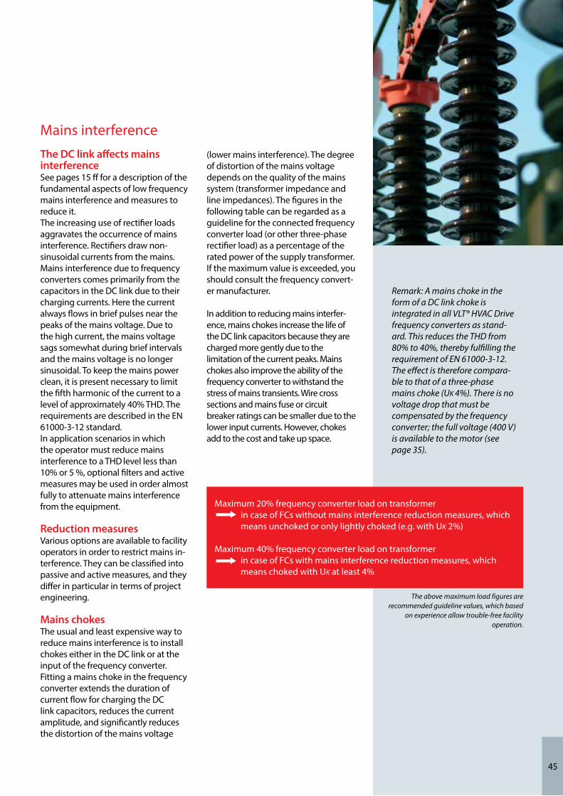
45
Mains interferenceThe DC link affects mains interferenceSee pages 15 ff for a description of the fundamental aspects of low frequency mains interference and measures to reduce it. The increasing use of rectifier loads aggravates the occurrence of mains interference. Rectifiers draw non-sinusoidal currents from the mains. Mains interference due to frequency converters comes primarily from the capacitors in the DC link due to their charging currents. Here the current always flows in brief pulses near the peaks of the mains voltage. Due to the high current, the mains voltage sags somewhat during brief intervals and the mains voltage is no longer sinusoidal. To keep the mains power clean, it is present necessary to limit the fifth harmonic of the current to a level of approximately 40% THD. The requirements are described in the EN 61000-3-12 standard.In application scenarios in which the operator must reduce mains interference to a THD level less than 10% or 5 %, optional filters and active measures may be used in order almost fully to attenuate mains interference from the equipment.
Reduction measuresVarious options are available to facility operators in order to restrict mains in-terference. They can be classified into passive and active measures, and they differ in particular in terms of project engineering.
Mains chokes The usual and least expensive way to reduce mains interference is to install chokes either in the DC link or at the input of the frequency converter.Fitting a mains choke in the frequency converter extends the duration of current flow for charging the DC link capacitors, reduces the current amplitude, and significantly reduces the distortion of the mains voltage
(lower mains interference). The degree of distortion of the mains voltage depends on the quality of the mains system (transformer impedance and line impedances). The figures in the following table can be regarded as a guideline for the connected frequency converter load (or other three-phase rectifier load) as a percentage of the rated power of the supply transformer. If the maximum value is exceeded, you should consult the frequency convert-er manufacturer.
In addition to reducing mains interfer-ence, mains chokes increase the life of the DC link capacitors because they are charged more gently due to the limitation of the current peaks. Mains chokes also improve the ability of the frequency converter to withstand the stress of mains transients. Wire cross sections and mains fuse or circuit breaker ratings can be smaller due to the lower input currents. However, chokes add to the cost and take up space.
Remark: A mains choke in the form of a DC link choke is integrated in all VLT® HVAC Drive frequency converters as stand-ard. This reduces the THD from 80% to 40%, thereby fulfilling the requirement of EN 61000-3-12. The effect is therefore compara-ble to that of a three-phase mains choke (UK 4%). There is no voltage drop that must be compensated by the frequency converter; the full voltage (400 V) is available to the motor (see page 35).
Maximum 20% frequency converter load on transformer in case of FCs without mains interference reduction measures, which means unchoked or only lightly choked (e.g. with UK 2%)
Maximum 40% frequency converter load on transformer in case of FCs with mains interference reduction measures, which means choked with UK at least 4%
The above maximum load figures are recommended guideline values, which based
on experience allow trouble-free facility operation.

46
Rectifiers with 12, 18, or 24 pulses per cycleIn practice, frequency converters with rectifiers having a large number of pulses per cycle are primarily found in the higher power range. They require special transformers for proper operation.
Passive filtersPassive harmonic filters, which consist of LC circuits, can be used in all situations. They have high efficiency, typically around 98.5% or better. The devices are very robust and, with the exception of cooling fans if present, usually maintenance-free. The following must be borne in mind with passive filters. If they are operated with no load, they act as capacitive reactive power sources due to the circulating current flowing in the filter. Depending on the specific applica-tion, it may be worthwhile to use a group of filters, possibly with selective connection and disconnection.
Active filters, active front ends and low harmonic drivesAn innovative approach, based on improved semiconductor devices and modern microprocessor technology, is to use active electronic filter systems. They constantly measure the mains power quality and use an active current source to feed specific waveforms into the mains system. The net result is a sinusoidal current.Compared with the previously described filter options, the architec-ture of this new generation of filters is complex because they require fast, high-resolution data acquisition and high computing power.
It is not possible to make a basic recommendation regarding any of the mains interference reduction measures mentioned here. What is important is to make the right decisions during the design and project engineering stage in order to obtain a drive system with high
Note: With the complex active measures there is a risk of totally missing the mark,since these meas-ures have the serious drawback that they cause interference in the fre-quency range above 2 kHz (see pages 18 ff).
A low harmonic drive frequency converter is a frequency converter with a built-in active filter that acts on the mains.
Practical aspects of EMC measures
availability, low mains interference, and low radio frequency interference. In any case, the following factors must be carefully analysed before taking any decisions regarding the reduction measures to be used:- Mains analysis- Exact overview of the mains topology- Space constraints in the available electrical equipment rooms- Options for main distribution or subdistribution systems
Step 3
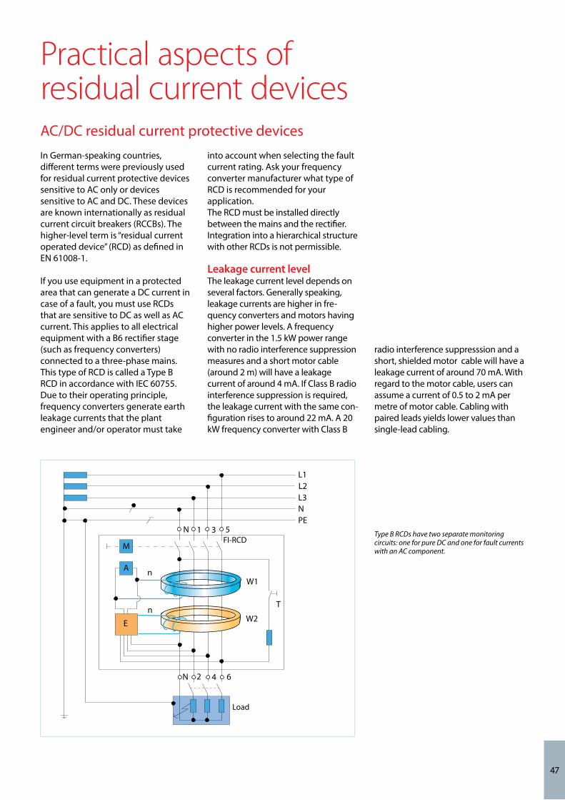
47
AC/DC residual current protective devicesIn German-speaking countries, different terms were previously used for residual current protective devices sensitive to AC only or devices sensitive to AC and DC. These devices are known internationally as residual current circuit breakers (RCCBs). The higher-level term is “residual current operated device” (RCD) as defined in EN 61008-1.
If you use equipment in a protected area that can generate a DC current in case of a fault, you must use RCDs that are sensitive to DC as well as AC current. This applies to all electrical equipment with a B6 rectifier stage (such as frequency converters) connected to a three-phase mains.This type of RCD is called a Type B RCD in accordance with IEC 60755. Due to their operating principle, frequency converters generate earth leakage currents that the plant engineer and/or operator must take
into account when selecting the fault current rating. Ask your frequency converter manufacturer what type of RCD is recommended for your application.The RCD must be installed directly between the mains and the rectifier. Integration into a hierarchical structure with other RCDs is not permissible.
Leakage current levelThe leakage current level depends on several factors. Generally speaking, leakage currents are higher in fre-quency converters and motors having higher power levels. A frequency converter in the 1.5 kW power range with no radio interference suppression measures and a short motor cable (around 2 m) will have a leakage current of around 4 mA. If Class B radio interference suppression is required, the leakage current with the same con-figuration rises to around 22 mA. A 20 kW frequency converter with Class B
FI-RCD
Load
M
A n
L1
W1
L2L3
PE
W2
T
N 2 4 6
n
E
N
N
1 3 5 Type B RCDs have two separate monitoring circuits: one for pure DC and one for fault currents with an AC component.
Practical aspects of residual current devices
radio interference suppresssion and a short, shielded motor cable will have a leakage current of around 70 mA. With regard to the motor cable, users can assume a current of 0.5 to 2 mA per metre of motor cable. Cabling with paired leads yields lower values than single-lead cabling.

48
Earthing measures in practiceEarthing measures are described in detail in the “Motors and cabling” section of Step 3 (pages 31 ff).If the application requires external filters, they must be fitted as close to the frequency converter as possible. The cable between the filter and the equipment should be a shielded cable, and the filter should be connected to the earth conductor on the mains side and the equipment side. It is also recommended to mount the filter flush with the surface and provide a low-impedance connection between the filter housing and ground.
Filters generate leakage currents that can be considerably higher than the rated value in case of a fault (phase drop-out or asymmetric load). To
avoid hazardous voltages, filters must therefore be earthed before power is switched on. With leakage currents of 3.5 mA and above, in accordance with EN 50178 or EN 60335 either: -the cross-section of the protective earth conductor must be 10 mm² or more;-or the protective earth conductor must be monitored for an open circuit;-or a second protective earth conduc-tor must be installed in addition. The leakage currents here are high-frequency interference signals. This requires earthing with low-imped-ance links bonded to a large surface area and connected to earth potential by the shortest possible route.
Motor protection and motor PTC thermistorFrequency converters assume the task of protecting the motor against excessive current. Thermistor sensors or thermal cutouts in the motor winding are used to provide the best possible motor protection. The signal is monitored via suitable input terminals on the frequency converter. Thermistors compliant with DIN 44081 or DIN 44082 are designed to have a resistance within a certain range at the rated response tempera-ture (RRT) (RRT – 5°C < 550 Ω; RRT + 5°C > 1330 Ω). Many converters have functions suitable for monitoring such thermistors. In the case of motors operated in explosion hazard areas, thermistor monitoring is allowed only with certified trip devices (see page 30).
The protective function of motor protection switches is limited to direct mains operation. In electrical systems with frequency converters, they can only provide motor protection in an emergency situation when the frequency converter is bypassed by a suitable circuit. The motor protection function of the switch is ineffective with frequency converter operation. Nevertheless, with proper dimension-ing it can be put to good use with converter-driven motors as a sort of three-phase circuit breaker that only protects the wiring.
Note: Even the best measures to counter mains interference and radio frequency interference are of no use if their implementation in the installa-tion does not conform to good EMC practice. Interference problems are inevitable in such cases.
Remark: Many frequency converters have a supplementary function called „thermal motor image“. The motor temperature is calculated from the motor data and the amount of power transferred to the motor. This function is usually implemented very conserva-tively and tends to trigger earlier than absolutely necessary. The actual ambient temperature at the start of the calculation process is usually not taken into account. However, this function can be used to provide a simple form of basic protection if no other form of motor protection is available.
Note: With VLT® HVAC Drive, terminals 50 and 54 are normally designated for connecting thermistors. This port is suitable for motor temperature monitoring using three to six PTC bead thermistors (standard configuration: three beads per motor).
Practical aspects of earthing and motor protection
Step 3

49
The basic technology of all frequency converters is the same, so ease of use is a decisive factor. Many functions, as well as integration in machines or systems, require a simple operating concept. It must fulfil all requirements for easy and reliable configuration and installation.The options range from simple and inexpensive numerical displays to convenient control panels that display data in text form. Simple control panels are adequate for the basic task of observing operating parameters such as current or voltage.
By contrast, control panels with convenience features allow the display to show additional parameters or present them all at the same time.Clear grouping of functions and easy manual operation are also possible, as well as options for access via software,
Simple operating concept
Graphic control panels offer ease of use and can display information in plain text.
a field bus, or even remote mainte-nance using a modem or the Internet.A modern frequency converter should be able to combine all of the operat-ing concepts mentioned below ina single device or to make them possi-ble and it should at least allow switching between manual and remote control at all times.
This control panel won the international iF Design Award for user friendliness in 2004. The LCP 102 was selected for this distinction from among 1000 entries from 34 countries in the category “man-machine and commu-nication interfaces”.
Practical aspects of operator control and data display
Easy commissioningFeatures such as Danfoss Smart Start considerably simplify the commissioning of converters. It guides the user through the basic converter settings.

50
Note: Ensure that the frequency converter you plan to engineer into the system has the right operating concept. A design that provides the greatest possible ease of use for parameter configuration and programming is an advantage, since nowadays the functionality of the drive is not the only significant factor. Fast, easy user operation, preferably intuitive, is also important. This is the only way to reduce the effort, and thus the cost of familiari-sation and the subsequent interaction times of employees responsible for working with frequency converters.
Integrated in the cabinet doorIn many facilities in which frequency converters are installed in cabinets, facility engineers should integrate the control panels in the cabinet doors to provide process visualisation. This is only possible with frequency convert-ers that have detachable control panels. With the control panel integrated in the cabinet door using a mounting frame, the frequency converter can be controlled without opening the cabinet door and its operating state and process data can be read out.
Operation under local controlThe basic requirement is support for local operation using a local control panel. Even in the era of networked communication, there are many tasks that require the ability to control the equipment directly – such as commis-sioning, testing, process optimisation and on-site maintenance activities in facilities.
In each of these cases, the operator or technician may need to be able to alter local values in order to incorporate the changes in the system directly and perform related tasks, such as fault diagnosis. For this purpose, the control panel should provide a simple and intuitive man-machine interface.
Clear displayThe ideal solution is a graphic display, since it allows the user to select the preferred language for the user interface and the basic display mode can show the essential parameters of the actual application.
To maintain clarity, this status infor-mation must be limited to the essential parameters and it must be possible to adapt or change the parameters at all times. It is also helpful to be able to block or hide certain functions according to the knowledge level of the operator and to limit parameter display and the ability to modify parameters to what is actually necessary for process adjustment and control.
With the large number of functions provided by modern frequency converters, which often have several hundred parameters for optimal adaptation, this reduces operator errors and thereby reduces expensive downtime and facility outages. Likewise, the display should have an integrated help function for the individual functions so that support is available to the commissioning technician or service technician at all
times, especially for rarely used parameters, in order to eliminate operator errors as much as possible here as well.
For the optimal use of integrated diagnostic functions, it is very helpful to be able to display graphic plots (“scope function”) in addition to alphanumeric data. In many cases this form of data display, such as ramp shapes and/or torque curves, makes troubleshooting easier.
Uniform conceptIn HVAC/R systems, a large number of frequency converters are used in a wide variety of applications. The converters, which usually are mostly from the same manufacturer, differ primarily in their power ratings and therefore in their size and appear-ance. A uniform operator interface for the frequency converters, with the same control panel over the entire power range, offers advantages for plant engineers and facility operators.
The basic principle is that simplifying the operator interface makes commis-sioning and troubleshooting (if necessary) faster and more effective. Consequently, concepts based on plug-and-play control panels have proven their value in practice.
Practical aspects of operator control and data display
Frequency converter parameters can also be config-ured and read out with the cabinet door closed.

Extended optionsIn addition to operation using a control panel, modern frequency converters usually support parameter configuration and data readout by a PC program. This software usually runs under Windows and supports several communication interfaces. It enables data exchange over a traditional RS 485 interface, a field bus (Profibus DPV1, Ethernet, etc.) or a USB interface.
Remark: The MCT 10 program is a Windows-based engineering tool for easy system engineering, parameter configuration and programming of VLT® HVAC Drive units.
In addition to parameter configuration, PC software for frequency converters enables users to
record process data or manage systems.
Practical aspects of control and parameter configuration with a PC
A clearly structured user interface provides a quick overview of all the drives in a system. A good program also allows users to manage large systems with many drives. Parameter configuration is possible online and offline. Ideally, the program also allows documents to be integrated into the system. Among other things, this makes it possible to access system electrical diagrams or operat-ing manuals from the program.

52
Bus systemsModern frequency converters are intelligent, which enables them to handle many tasks in drive systems. Nevertheless, even now many devices operate with only four data points in a control system or under control of a DDC and act only as speed controllers. This means that operators do not make full use of the many useful functions and do not have access to stored system data. However, it is easy for users to exploit the full potential of frequency converters by using a field bus link, such as BACnet, to integrate them in the control system. With just one hardware data point, users have full access to all objects of the installed frequency converters. Cabling and commissioning are simpler, which leads to cost savings from the installation phase onward. A large volume of data for effective facility management is available. Decoding of collective fault messages allows faults to be diagnosed, even remotely and the right fault correction actions to be initiated.
Better alarm managementDetailed alarm messages simplify the pin-pointing of possible fault causes and thereby provide effective support for remote facility monitoring. Remote maintenance using modems or the Internet allows state and/or fault messages to be displayed quickly, even with remote systems or system components.
Better facility managementThe control room operator is able to monitor and adjust all frequency converter settings remotely. Status data, such as the output frequency or power consumption, can be read out and processed at any time. Additional data for effective energy and peak load management is available without additional components.
Lower installation costsIt is not necessary to equip every frequency converter with a display. The user or operator can access all relevant frequency converter data via the control system.
Simplified wiring with two-wire connectionsUnused frequency converter inputs and outputs can be used as I/O ports to integrate other components in the application or building, such as sen-sors, filters and limit switches, into the control system. In many cases adding additional I/O points are cheaper than installing and programming an exter-nal/ additional DDC controler. There is no need for input and output components, since a single hardware data point is sufficient for controlling the frequency converter.
Monitoring functions such as motor thermistor monitoring, dry pump pro-tection, etc., as well as output and op-erating hours counters, are available without additional components.
Practical aspects of data exchange
Simplified commissioningParameter configuration is performed from the control room. All settings can be copied quickly and easily from one frequency converter to another. A persistent backup copy of the settings can be stored in the display memory. Designers and commissioning staff can document the settings at the press of a button.
Note: The RGO 100 Remote Guardian Option sets new standards for monitoring, maintenance and alarm processing for frequency converters in one or more facilities. It supports typical tasks such as remote action, remote maintenance, alarm process-ing and data logging for system configuration and system monitoring.
Step 3
Busses for VLT® HVAC DriveIntegrated Optional Modbus RTU MCA 101 – Profibus DP V1FC Protocol MCA 108 – LONworksN2 Metasys MCA 109 – BACnet (Extended)FLN ApogeeBACnet (Standard) MCA 120 – Profinet
MCA 121 – EtherNet/IPMCA 122 – Modbus TCP

53
VLT® HVAC Drive
Reference scaling
Motorcontroller
Application
Process
Controller
PID
Feed back
PID process controller block diagram
StorageLike all electronic equipment, fre-quency converters must be stored in a dry place. The manufacturer’s specifications in this regard must be observed. Some manufacturers specify that the device must be formed periodically. For this purpose, the user must connect the device to a
defined voltage for a certain period. This forming is necessary due to the aging of the capacitors in the device’s DC link. The aging rate depends on the quality of the capacitors used in the device. Forming counters the aging process.
Remark: Due to the quality of the capacitors used and the flexible, order-specific manufacturing concept, this procedure is not necessary with VLT® HVAC Drive frequency converters.
Practical aspects of additional selection factorsProcess controllerModern frequency converters are intelligent drive controllers. They can perform tasks and functions traditio-nally handled by PLC/DDCs. The implemented process controllers can also be used to build independent
high-precision control loops. This facility is especially useful when retrofitting systems with insufficient DDC capacity or no DDC at all. Active process parameter transducers (actual value transmitters for flow,
pressure or level) can be powered from the frequency converter’s 24 V DC control voltage if it has sufficient power capacity.
MaintenanceMost frequency converters are virtually maintenance-free. High-power frequency converters have built-in filter mats which must be cleaned from time to time by the operator, depending on the dust exposure.
Remark: Danfoss VLT® frequency converter models up to 90 kW are maintenance-free. Models rated at 110 kW or more have filter mats integrated in the cooling fans. They must be checked periodically and cleaned as necessary.
However, it must be noted that frequency converter manufacturers specify maintenance intervals for the cooling fans (approximately 3 years) and capacitors (approximately 5 years) in their equipment.

54
Danfoss VLT® HVAC Drives are specifi-cally designed for use in HVAC applications.
Dedicated fan features• Velocity-to-flow conversion• Intelligent AHU functions• Fire Override Mode• Extends BMS capacity• Resonance Monitoring• Stairwell Pressurisation• 4 x PID controller
Dedicated pump featuresThe VLT® HVAC Drive offers a vastnumber of pump-specific featuresdeveloped in cooperation with OEMs,contractors and manufacturersaround the world.• Embedded Pump Cascade Controller• Vital water supply• Sleep Mode• Dry Pump Protection and• End of Curve• Auto tuning of the PI controllers
• Flow compensation• No/low flow• Dry pump protection• Optional sensorless pump control
Dedicated compressor features• Premium torque control• Replace a cascade with a single
compressor• Set point in temperature• Fewer starts and stops• Quick start-up improving energy efficiency
Unlike many other makes, all impor-tant components and functions are integrated as standard:• Built-in RFI filter compliant with
EN 61800-3 category C1 (Class B limits as defined by EN 55011)
• Built-in mains interference chokes (UK 4%)
• AEO function for especially high energy savings• USB interface
• Real time clock• VLT® HVAC Drive in low harmonic version• Integrated cascade controller for
three fans, pumps or compressors • Optional active and passive mains
filters for additional harmonic reduction• Optional sine-wave filter and du/dt
filter for all power ratings• RS 485 serial interface• Dimensioned for long service life• Full mains voltage at the output• Long motor cables may be con-
nected (150 m shielded or 300 m unshielded)
• PTC thermistor monitoring• Outlet flow monitoring
Extensive information is available from your Danfoss contact person or the web. A considerable amount of information is available for download-ing on the website.
www.danfoss.com/vlt
VLT® HVAC Drive units are available with power ratings from
1.1 kW to 1.4 MW and a rated voltage of 200 - 690 V.
VLT® Low Harmonic Drive versions are also available for reduced
mains interference.
VLT® HVAC Drive

55
CE mark
The CE (Communauté européenne) mark is intended to eliminate technical barriers to free trade between the EC and EFTA states (inside the ECU). The CE mark indicates that the product manufacturer conforms to all applica-
ble EC directives which have been transposed into national law. The CE mark says nothing about the quality of the product. Technical specifications cannot be deduced from the CE mark. The directives that must be observed
within the scope of use of frequency converters include the Machinery Directive, the EMC Directive, and the Low-Voltage Directive.
Machinery Directiveve
Application of the Machinery Direc-tive 2006/42/EC became mandatory on 29 December 2009. Machinery Directive 98/37/EC was thereby abrogated. The key message of the directive is that a machine, consisting of an aggregate of interconnected components or devices of which at
least one is able to move, must be fashioned such that the safety and health of people and as appropriate, domestic animals or goods are not endangered as long as the machine is correctly installed, suitably main-tained and used as intended. Fre-quency converters are classified as
EMC Directive
The EMC Directive 2004/108/EC has been in force since 20 July 2007. Its key message is that devices that are liable to generate electromagnetic interference or whose operation can be adversely affected by such interfer-ence must be fashioned such that the generation of electromagnetic interference is limited, insofar as radio
and telecommunication devices as well as other devices exhibit a suitable degree of immunity to electromag-netic interference when operated according to their intended use, such that operation according to the intended use is possible. As frequency converters are not devices that can be operated independently and are not
generally available, it is not necessary to document conformity to the EMC Directive by means of a CE mark or an EC declaration of conformity. Never-theless, Danfoss frequency converters have the CE mark as an indication of conformity to the EMC Directive, and a declaration of conformity is avail-able.
Low-Voltage Directive
The Low-Voltage Directive 73/23/EEC took force on 11 June 1979; the transition period ended on 31 December 1996. The key message is that electrical equipment for use with a nominal voltage of 50 to 1000 V AC or 75 to 1600 V DC must be fashioned such that the safety and health of people and livestock and the preser-vation of material worth are not
endangered as long as the equipment is properly installed and maintained and used as intended. As frequency converters are electrical equipment operating in the specified voltage range, they are subject to the Low-Voltage Directive and all devices produced from 1 January 1997 onward must bear a CE mark.
electronic components and are therefore not subject to the Machin-ery Directive. When plant engineering firms use frequency converters in machines, they generate a manufac-turer’s declaration stating that the machine conforms to all relevant statutes and security measures.
Note: Manufacturers of machines or systems should ensure that the frequency converters they use bear the CE mark. An EC declaration of conform-ity must be provided on request.
Directives related to frequency converters

56
AActive filters 17, 18, 20, 46Active front end 17, 19, 20, 46Aggressive atmosphere/ gases 28Air conditioning 27Air flow 27, 29Ambient temperature 27Ammonia 28Amplitude 15Apparent power 16Asymmetric load 24ATEX 30Automatic energy optimisation (AEO) 9, 54Availability 8, 16
BBackup power systems 24Bearing current 35Bearing stress 35Bus system 52
CCabinet heating 27Cabinet mounting (central mounting) 25Cable glands (regular and EMC) 39Capacitive coupling 14Capacitor 17Capacity increase 8CE mark 55Central compensation 18Characteristic curves 15Chlorine 28Chokes 17, 23, 24, 37, 45Climatic conditions 27Common mode filter 36Coated PCBs 28Commissioning costs 10Compensation current 18Condensation 27Conductive coupling 14Conductor 37, 38, 43Configuration 51Connected load 8Connection conditions 15Constant characteristic curve 41, 42Contact points 38Contamination 28Control loop 53Control panel 49, 50Control range 8Control room 27Cooling 27, 29Corrosion 28Cos φ 23
Cost factor 10Coupling mechanism 14Current consumption 15Current spectrum
DData display 49, 50Data exchange 51DC link 17, 19, 23, 27, 45 DC link voltage 34, 37DC voltage 17, 20 DDC 53Decommissioning costs 10Design checklist 6, 62Directives 15, 55Disposal costs 10Distortion 15Distortion spectrum 18Downtime costs 10Drive system 8Dust exposure 29dU/dt filter 20, 35, 36, 37
EEarthing 38, 48Earthed neutral conductor 12EC motors 33, 34Efficiency classes 31, 41Electromagnetic waves 14Emax control 8EMC cable glands 37EMC characteristics 12EMC Directive 55EMC 12, 13, 14, 21, 25, 38, 44Energy costs 10Energy efficiency 7Energy network 15Energy savings 8Environment (1 or 2) 21, 22, 23, 24, 39Environmental conditions 7, 25Environmental costs 10Explosion protection (ATEX) 30
FFacility earthing 38Facility operator 15Facility services designer 7Filter mats 29Flow 8Fluid flow machines 9, 41Fourier analysis 15Full load 8
Index

57
GGenerator 24Generic standard 21Ground connection 38Ground loop 38Group compensation 18
HHarmonic calculation 16, 24Harmonic current 16, 18Harmonic distortion 15, 17, 18Harmonic filter 16, 17, 42, 43Harmonic load 24Harmonics 14Heat loss/dissipation 27, 35Heat sink 29Hydrogen fluoride 28Hydrogen sulphide 28
IIE classes 31IEC enclosures 32Ignition protection class 30Individual compensation 18Individual earthing 12Inductive coupling 14Industrial environment 22, 24Industrial mains 15Initial capital costs 10Input rectifier 15Installation conditions 25Installation costs 10Insulation stress 33Interference emission 13Interference fields 14Interference immunity 13, 2Interference level 21Interference sink 14Interference source 14Interference transmission 12IP ratings 26IT mains system 12
LLC filter, circuits 34, 46Leakage current 47, 48Life cycle costs (LCC) 7, 10Lightning strikes 3Linear characteristic 41, 42Load asymmetry 24Load characteristic 42Load shock 8Low Harmonic Drive (LHD) 17, 19, 46Low-Voltage Directive 55Low-voltage grid 24
MMachinery Directive 55Magnetic field 14Mains analysis 16, 24Mains calculation 16, 46Mains chokes 44, 45Mains filter 21Mains fuse/ circuit breaker 44Mains impedance 24Mains interference 15, 16-20, 44Mains power quality 15, 16, 17Mains system 8, 12, 15, 23Mains transients 17, 23, 24Mains type 12Maintenance costs 7, 10Maintenance 53Material wear 8Minimum efficiency performance standards (MEPS) 31, 32Motor bearing 33, 36Motor cable 35, 36, 37, 39, 40Motor efficiency 31Motor insulation 36, 37Mounting clearance 27Multi-motor operation 41
NNeutral conductor, seperate/ combined 12Nitrogen 28Nonlinear characteristic 42Non- sinusodial currents 15
OOperating costs 8, 10Operating point 8Operating site (EMC) 21, 22, 25Output Filter 36, 37, 38Overall system 8Overload capacity 41Oversynchronous range 8Ozone 28
PPanel mounting kit 50Parallel operation 41Partial-load operation 8, 9Passive filters 17, 20, 46Payback time 8Peak currents 8Permanent magnet motors (PM/ PMSM) 33, 34Phase shift 23Piping system 8Potential energy savings 8, 9Power consumption 9Power factor 17, 19, 23

58
Pressure 8Process controller 53Product standard 21Project engineering 7Proportionality rules 9Protection ratings 25, 26Protective earth conductor 12Provision costs 8PTB approval 30PTC thermistor 30, 43, 48, 54Public power grid 15Pump systems 10
QQuality 7
RRadiation coupling 14Radiation 39Radio frequency interference 21, 22, 44Rated motor current 8, 41RCD 47Reactive current 9, 35Reactive power 24Rectifier 15, 17, 24, 46Reduction/Derating 13, 42Relative humidity 27Repair costs 8Residential environment 22, 24Residual current device 47Resonances 24Retrofit 8, 36RFI filter 21, 42RFI 21, 36, 44RMS value 16Run time, pump 10
SScreening measures 39Second-level protection 21Service life 8, 27, 29, 42Shielding 39Short circuit 21Sine-wave distortion 15Sine-wave filter 30, 36Sinusoidal voltage 15Special environment 22Staggered windings 24Starting current limiting 8
TTHD (total harmonic distortion) 15, 17, 18, 20, 45Thermal stress 35Three- phase induction motors (TPIM) 33Throttle valve 9, 10TN mains systems 12Torque characteristic 8, 41, 42Transformer (load, utilisation) 24, 45Transients 18, 23, 24, 41TT mains system 12
UUndervoltage losses 16
VV/f characteristic 9Valve control 10Varistor 23Voltage drop 36, 37, 41Voltage sags 8Volumetric flow 10
WWall mounting (local) 25Wavelength 14Winding 35
Index

59
AFE Active Front EndAHF Advanced Harmonic FiltersATEX Atmosphère explosibleCE Communauté EuropéenneCEMEP European Committee of Manufaturers of Electrical Machines and Power ElectronicsDC Duty CycleDDC Direct Digital ControlEff Efficiency classes (motors)EMD Electromagnetic dischargeEMC Electromagnetic compatibilityEN European Norm (standard)FC Frequency converterHVAC Heating Ventilation and Air ConditioningIE International Efficiency (motors) IEC International Electrotechnical CommissionIP ratings Ingress Protection ratingsLCC Life Cycle CostLHD Low Harmonic DriveMEPS Minimum Efficiency Performance StandardsPCB Printed Circuit BoardPFC Power Factor CorrectionPTB Physikalisch - Technische BundesanstaltPTC Positive Temperature CoefficientRCCB Residual Current Circuit BreakerRCD Residual Current DeviceRFI Radio Frequency InterferenceTHD Total Harmonic Distortion
Abbreviations

Notes


Mains systems Ambient conditions
Mains type: TN-C, TN-S, TT, IT
TN-S is favourable with regard to EMC. Special measures are necessary with IT mains systems.
EMC Observe the EMC standards and their limits.
Mains interference (low frequency)
How much mains interference is already present? What is the maximum allowable harmonic current (THD)?
Radio frequency interference(high frequency)
What is the environment class (1 or 2) of the facility?
Power factor correction equipment
Fit power factor correction equipment with chokes.
Mains transients Are the FCs adequately protected against main transients?
Max. transformerutilisation
Rule of thumb for transformer load: approximately 40% FC load (with choke).
Operation with a standby generator
Other conditions apply to the FC here than with mains operation.
Installation locationFC mounted centrally in a cabinet (IP20) or locally on the wall (IP54 or IP66)?
Cooling conceptCooling of cabinet and FC; high temperatures damage all types of electronic components.
Aggressive atmosphere/ gases
Coated PCBs for protection against aggressive gases: hydrogen sulphide (H2S), chorine (Cl2 and ammonia (NH3).
Dust exposure Dust on or in the FC reduces cooling effectiveness.
Potentially explosive atmospheres
Here FCs are subject torestrictions.
Frequency Converter Design ChecklistThe four steps of basic frequency converter design for operationally reliable HVAC/R applications
Starting after the determination of the drive task and torque characteristicsIf you verify all items in this checklist, you can confidently look forward to trouble-free facility operation.

www.danfoss.com/drives
Motor and cabling Frequency converter
Dimensioning and selection
Dimension according to motor current. Take voltage drops into account.
Special caseMulti-motor operation Special conditions apply here.
Radio frequency interference (high frequency)
Specify suitable RFI filters for the actual EMC environment.
Mains interference(low frequency)
Use mains interference chokes to reduce harmonic currents.
Earthing measures Have measures to counter leakage currents been taken?
RCDs Use only type B RCDs.
Motor protection andmotor PTC thermistor
The FC monitors the motor PTC thermistor.(EX zone PTB approval)
Operator control and data display
Operator control and data display using a text display (installed in the cabinet door).
Data exchange (bus systems)
Over bus systems (e.g. Profibus) or over conventional wiring between terminals.
Process controller FCs can perform DDC tasks or establish autonomous control loops.
Maintenance Is the frequency converter maintenance-free?
Motor efficiencyclasses Selecting an energy-efficient motor
Motor suitability for FC operation
Ask the motor supplier to confirm suitability for FC operation.
Output filter:sine-wave or du/dt
Supplementary filters for special applications.
Motor cableUse a cable with suitable shielding.Observe the maximum connected cable length specification of the FC.
Earthing measures Ensure proper potential equalisation. Is an earthing plan available?
Shieldingmeasures
Use EMC cable glands and terminate the shield correctly.

Environmentally responsible
VLT® products are manufactured with respect for the safety and well-being of people and the environment.
All activities are planned and per-formed taking into account the indi-vidual employee, the work environ-ment and the external environment. Production takes place with a mini-mum of noise, smoke or other pollu-tion and environmentally safe disposal of the products is pre-prepared.
UN Global CompactDanfoss has signed the UN Global Compact on social and environmental responsibility and our companies act responsibly towards local societies.
EU Directives All factories are certified according to ISO 14001 standard. All products fulfil the EU Directives for General Product Safety and the Machinery directive. Danfoss VLT Drives is, in all product series, implementing the EU Directive concerning Hazardous Substances in Electrical and Electrical Equipment (RoHS) and is designing all new prod-uct series according to the EU Direc-tive on Waste Electrical and Electronic Equipment (WEEE).
Impact on energy savingsOne year’s energy savings from our annual production of VLT® drives will save the energy equivalent to the energy production from a major power plant. Better process control at the same time improves product quality and reduces waste and wear on equipment.
What VLT® is all aboutDanfoss VLT Drives is the world leader among dedicated drives providers – and still gaining market share.
Dedicated to drivesDedication has been a key word since 1968, when Danfoss introduced the world’s first mass produced variable speed drive for AC motors – and named it VLT®.
Twenty five hundred employees develop, manufacture, sell and service drives and soft starters in more than one hundred countries, focused only on drives and soft starters.
Intelligent and innovative Developers at Danfoss VLT Drives have fully adopted modular principles in development as well as design, pro-duction and configuration.
Tomorrow’s features are developed in parallel using dedicated technology platforms. This allows the develop-ment of all elements to take place in parallel, at the same time reducing time to market and ensuring that customers always enjoy the benefits of the latest features.
Rely on the expertsWe take responsibility for every element of our products. The fact that we develop and produce our own features, hardware, software, power modules, printed circuit boards, and accessories is your guarantee of reliable products.
Local backup – globallyVLT® motor controllers are operating in applications all over the world and Danfoss VLT Drives’ experts located in more than 100 countries are ready to support our customers with applica-tion advice and service wherever they may be.
Danfoss VLT Drives experts don’t stop until the customer’s drive challenges are solved.
DKDD.PB.36.U2.02 VLT® is a trademark of Danfoss A/S Produced by PE-MMSC 2014.09