Embed Size (px)
Citation preview

DESIGN |SUPPLY | INSTALL
5 Aluminium Close
Edgeworth NSW 2285
P: 02 4958 7555
> hunterpumps.com
HUNTER PUMPS
DOSING
SYSTEM
MANUAL
Operating and
Instructions

DosingConveying
Control
LiquidsGasesSystems
Original Operating Instructions
© Lutz-Jesco GmbH 2013
BA-10241-02-V01
Solenoid-Diaphragm Dosing PumpMAGDOS LD
Operating Instructions
Read the Operating Instructions!
The user is responsible for installation and operation related mistakes!
Product descriptionProperties10
Solenoid-Diaphragm Dosing Pump MAGDOS LD Operating Instructions
BA-10241-02-V01
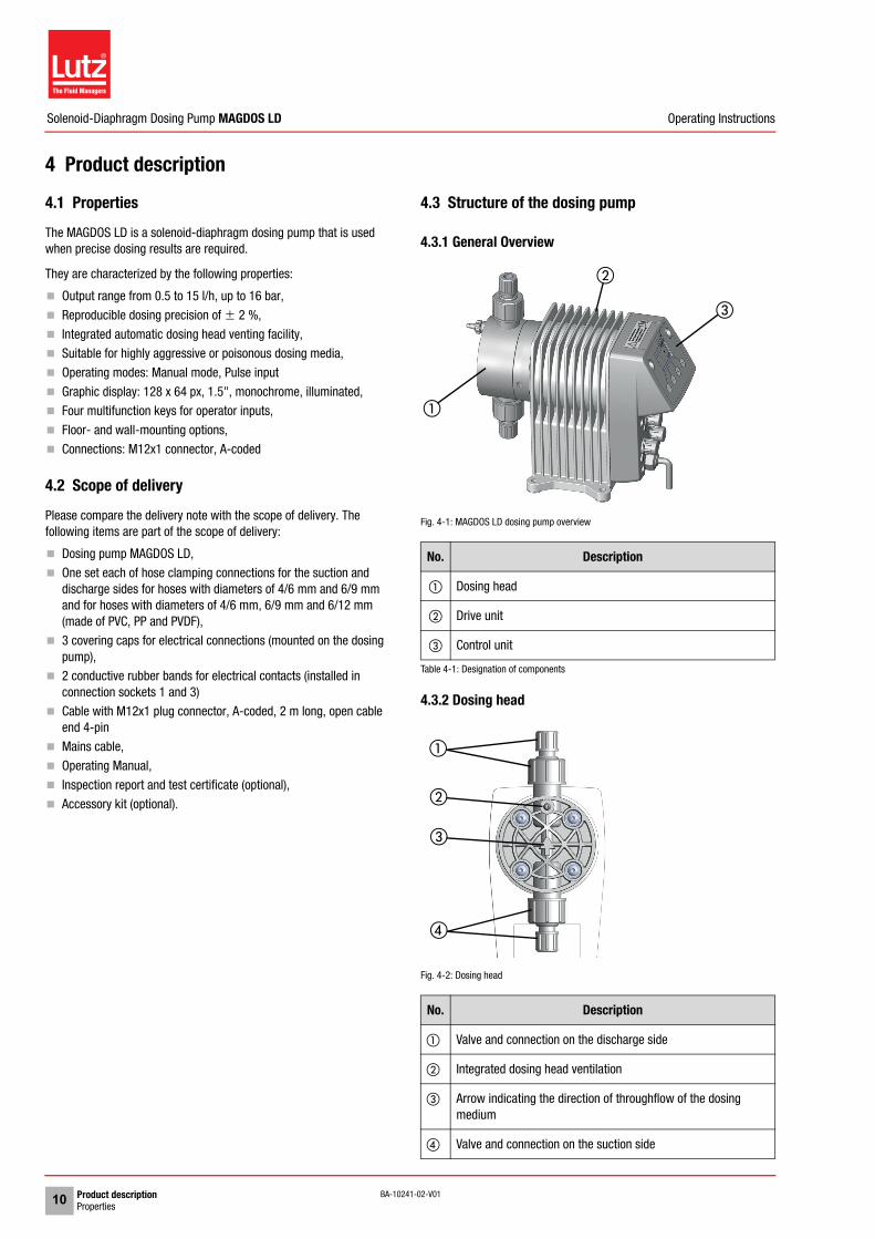
4 Product description4.1 PropertiesThe MAGDOS LD is a solenoid-diaphragm dosing pump that is used when precise dosing results are required.
They are characterized by the following properties:
Output range from 0.5 to 15 l/h, up to 16 bar,
Reproducible dosing precision of � 2 %,
Integrated automatic dosing head venting facility, Suitable for highly aggressive or poisonous dosing media,
Operating modes: Manual mode, Pulse input
Graphic display: 128 x 64 px, 1.5", monochrome, illuminated, Four multifunction keys for operator inputs,
Floor- and wall-mounting options,
Connections: M12x1 connector, A-coded
4.2 Scope of deliveryPlease compare the delivery note with the scope of delivery. The following items are part of the scope of delivery:
Dosing pump MAGDOS LD,
One set each of hose clamping connections for the suction and discharge sides for hoses with diameters of 4/6 mm and 6/9 mm and for hoses with diameters of 4/6 mm, 6/9 mm and 6/12 mm (made of PVC, PP and PVDF),
3 covering caps for electrical connections (mounted on the dosing pump),
2 conductive rubber bands for electrical contacts (installed in connection sockets 1 and 3)
Cable with M12x1 plug connector, A-coded, 2 m long, open cable end 4-pin
Mains cable,
Operating Manual,
Inspection report and test certificate (optional),
Accessory kit (optional).
4.3 Structure of the dosing pump
4.3.1 General Overview
Fig. 4-1: MAGDOS LD dosing pump overview
4.3.2 Dosing head
Fig. 4-2: Dosing head
No. Description
� Dosing head
� Drive unit
� Control unit
Table 4-1: Designation of components
No. Description
� Valve and connection on the discharge side
� Integrated dosing head ventilation
� Arrow indicating the direction of throughflow of the dosing medium
� Valve and connection on the suction side
�
�
�
�
�
�
�

Product descriptionFunction description 11© Lutz-Jesco GmbH 2013
Subject to technical changes.131022
Solenoid-Diaphragm Dosing Pump MAGDOS LD Operating Instructions
BA-10241-02-V01
4.3.3 Control elements
Fig. 4-3: Controller of MAGDOS LD dosing pump
4.4 Function descriptionDosing pumps are positive displacement pumps. They are used if precisely defined delivery of a medium is necessary. A constant volume per stroke or time is delivered.
The system delivers or meters the dosing medium by means of a repeated sequence of suction strokes followed by pressure strokes. This results in a pulsing flow.
If the dosing pump is in the suction stroke phase, the diaphragm is pulled into the rear final position. Due to the resulting vacuum in the dosing head, the discharge valve closes, the suction valve opens and dosing medium flows from the suction line into the dosing head.
If the dosing pump is in the pressure stroke phase, the diaphragm is moved into the front final position. Due to the pressure in the dosing head, the suction valve closes and the dosing medium flows through the discharge valve from the dosing head into the pressurised pipe.
4.5 Rating plateThere is information on the equipment about safety or the product's way of functioning. The information must stay legible for the duration of the service life of the product.
Fig. 4-4: Rating plate MAGDOS LD
No. Description
� Graphic display
� Multifunction keys on the contol unit for operator inputs
� Connection sockets for external operation or connecting acces-sories
� Mains cable for power supply
Table 4-2: Designation of components
�
�
�
�
No. Description
� Product, type, nominal size
� Part number
� Type of material of dosing head/ type of material of seals
� Maximum delivery capacity at average pressure
� Maximum delivery capacity at maximum pressure
� Protection classification
� Power supply
Frequency
Power consumption
� WEEE label
� Label showing conformity with applicable European directives
Month / year of manufacture
� Serial number
Table 4-3: Rating plate
Material: Max. XXX l/h at X barMax. XXX l/h at X barIP XX, XXX V, XXXX Hz, XX W
Lutz-Jesco GmbH30900 Wedemark Germany
XX/XXXXS/N: XXXXXXXXXXP/N:
Made in Germany*102A12345678*
*12345678012345*
MAGDOS LD
�
�
�
�
�
� �
�
�
�

Technical dataDelivery capacity data12
Solenoid-Diaphragm Dosing Pump MAGDOS LD Operating Instructions
BA-10241-02-V01
5 Technical data5.1 Delivery capacity dataPlease note that some of this data only represents guide values. The actual capacity of a dosing pump depends on various factors. For approximate values of the delivery capacity at different pressures, refer to „Delivery characteristic curves“ (see page 44).
5.2 Operating conditions and limits
* Use of the dosing pump at ambient temperatures below 5 °C must be checked individually. In those cases please contact the manufacturer.
** With a viscosity of ~300 mPa s and above, you must use spring-loaded valves.
*** If the viscosity is above 1000 mPa s, this must be checked individually and the stroke frequency must be between 50 and 100 strokes/min.
Information ValueMAGDOS LD size
05 1 2 4 6 10 15
Delivery capacity at max. backpressurel/h 0.36 0.76 1.9 3.4 6.2 9.0 13
ml/stroke 0.05 0.05 0.2 0.31 0.57 0.83 0.86
Max. delivery pressure bar 16 8 6 3
Delivery capacity at average backpressurel/h 0.54 1.1 2.3 3.8 6.8 10 15.3
ml/stroke 0.08 0.08 0.24 0.35 0.63 0.92 1.0
Average delivery pressure bar 8 4 3 1
Max. stroke frequency min-1 120 250 160 180 250
Suction height for non-gassing media (with a filled suction line)
mWS 5 3 2
Table 5-1: Output data
Information ValueMAGDOS LD size
05 – 15
Maximum ambient temperature °C 5 – 45 (5 – 40 with PVC parts)*
Relative humidity % Max. 90
Max. sound pressure level (depressurised) dB(A) 68 – 75
Max. sound pressure level (at test pres-sure)
dB(A) 65 – 70
Max. supply pressure mbar 800
Viscosity limits mPa s 300** / 1000***
Adjustable dosing range % 0 – 100
Table 5-2: Operating conditions and limits
Technical dataElectrical specifications 13© Lutz-Jesco GmbH 2013
Subject to technical changes.131022
Solenoid-Diaphragm Dosing Pump MAGDOS LD Operating Instructions
BA-10241-02-V01
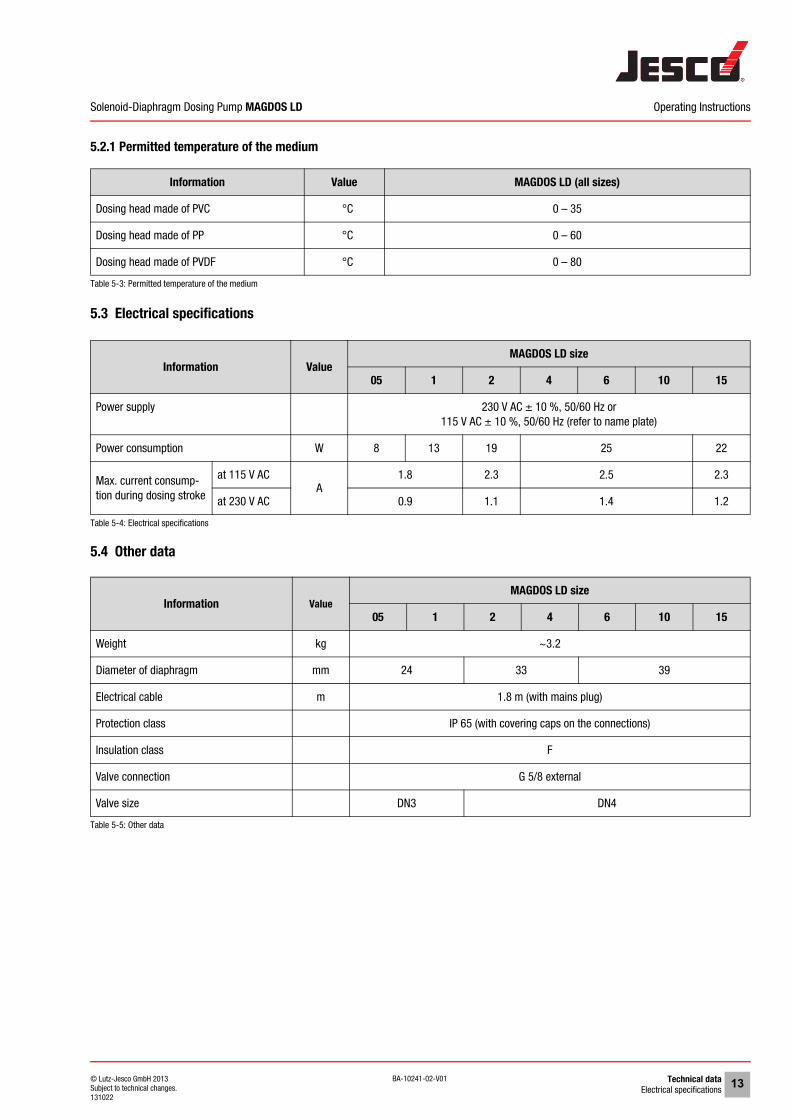
5.2.1 Permitted temperature of the medium
5.3 Electrical specifications
5.4 Other data
Information Value MAGDOS LD (all sizes)
Dosing head made of PVC °C 0 – 35
Dosing head made of PP °C 0 – 60
Dosing head made of PVDF °C 0 – 80
Table 5-3: Permitted temperature of the medium
Information ValueMAGDOS LD size
05 1 2 4 6 10 15
Power supply 230 V AC ± 10 %, 50/60 Hz or115 V AC ± 10 %, 50/60 Hz (refer to name plate)
Power consumption W 8 13 19 25 22
Max. current consump-tion during dosing stroke
at 115 V ACA
1.8 2.3 2.5 2.3
at 230 V AC 0.9 1.1 1.4 1.2
Table 5-4: Electrical specifications
Information ValueMAGDOS LD size
05 1 2 4 6 10 15
Weight kg ~3.2
Diameter of diaphragm mm 24 33 39
Electrical cable m 1.8 m (with mains plug)
Protection class IP 65 (with covering caps on the connections)
Insulation class F
Valve connection G 5/8 external
Valve size DN3 DN4
Table 5-5: Other data

Dimensions14
Solenoid-Diaphragm Dosing Pump MAGDOS LD Operating Instructions
BA-10241-02-V01
6 DimensionsAll dimensions in mm
Fig. 6-1: Dimensional drawing MAGDOS LD
������
�������
��
��
��������� �
�������
�������
����
�����
������
�����
���� ����
Connection Material Size Nominal width L
Hose clip PVC / PP / PVDF
4/6 mm DN4 31
1/4x3/8" 1/4" 34
6/9 mm DN6 34
6/12 mm DN6 15
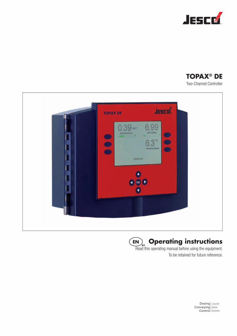
TOPAX® DETwo-Channel Controller
EN01
Operating instructionsRead this operating manual before using the equipment.
To be retained for future reference.
DosingConveying
Control
Liquids
Gases
Systems

Technical data | BA-40400-01-V09 | 5
Operating instructions
3 Technical data
Supply voltage 90 … 264 VAC, 47 … 63 Hz
Power consumption approx. 24 W
Housing dimensions 302 x 231 x 108 mm (W x H x D) wall-mounted housing
Display Graphic colour display 5.7 inch, 320 x 240 pixels (RGB), with background lighting
Keyboard Keyboard with touch keys
Measurement inputs(potential-free)
- inputs for disinfection, pH value, REDOX potential, temperature
Control characteristic for 2 inputs(disinfection, pH value)
P, PI, PD or PID performancesFixed value regulation, standard channel selectable with disturbance variable feed forward2-side controller
Control parameters Xp: 1…500%, Tn: 1…200 minutes, Tv: 1...1200 seconds
Measurement input Disinfection open amperimetric electrode with mechanical cleaning (excess chlorine detector with 2 electrodes, CS 120)Measuring range adjustable from: 0-1,00 mg/l, 0-2,00 mg/l, 0-5,00 mg/l oder 0-10,00 mg/l. Connection via series terminals*
Potentiostat (PM)Measuring range adjustable from: 0-1,00 mg/l or 0-2,00 mg/l
Encapsulated electrode 20 mA type with supply of the measuring cell (24 VDC), measuring range depending on measuring cellsMeasuring range adjustable from:0 – 1,00 mg/l, 0 – 2,00 mg/l, 0 – 5,00 mg/l or 0 – 10,00 mg/l
Measuring input for pH value Measuring range pH 0 … 14 Connection via series terminals*
REDOX potential measuring input (for disinfection)
Measuring range 0 ... 1000 mV
Connection via series terminals*
Temperature measuring input - Pt 100
Measuring range -10°C … +100°C
two-leader connection by means of line-up terminals*
Total chlorine measuring input Encapsulated electrodeMeasuring range adjustable from:0 – -1,00 mg/l, 0 – 2,00 mg/l, 0 – 5,00 mg/l or 0 – 10 mg/l
Disturbance variable input (option-ally available)
0...20 mA or 4...20 mADisturbance factor: 0.1 … 10 times amplification
Digital inputs - Low level alert input for metering pump 1- alarm level input for metering pump 1- Low level alert input for metering pump 2- Alarm level input for metering pump 2- measuring water shortage disconnection of the regulating function with alarm (external switch off)
Controller outputs Electronic output(optocouplers)
- 48 VDC; 250 mA (Pulse frequency 10 … 350 Impulses/min)
Relay output - ON/OFF- pulse frequency 10 … 100 Impulses/min- Pulse length 10 … 3600 seconds- 3-point step output with- Position feedback value of the Potentiometer 1 … 10 kOhm
Continuous output - 0/4 … 20 mA, max. load 500 ohms
Alarm output Relay output as collective alarm for the measuring size of Disinfection, pH value, redox potential, temperature and conductivity as potential free changer
Measurement alarm min. and max. alarm freely adjustable, time delay adjustable: max. 200 min
Safety cutout To prevent over metering (Y-alarm), time delay adjustable: max. 200 minutes
Current outputs for remote trans-mission of measuring values- Disinfection- pH value- Redox potential- Temperature
0/4 … 20 mA possible spreading; max. load 500 ohms potential free
useful spreading >50 % with measuring input Disinfection and 0/4 ... 20 mA>10% during measurement input of pH-value and redox potential
Computer interface (optional) RS 485
Load capacity of the relay 230 V AC, 3A
Protection class IP 65 with locked screw connections
Ambient temperature -5°C … +45°C
Air humidity 95 % non-condensing
*) max. 0.5 mm² with cable end sleeve and max. 1.0 mm² without cable end sleeve.

6 | BA-40400-01-V09 | Technical data
Two-Channel Controller TOPAX DE®
3.1 Recommended cablesRecommended cables for the different connections and applications:
Connections and applications Dimensions TypesMains voltage M20 X 1.5 NYM-I 3 x 1.5 mm (9.1 mm)
Relay output (ATE- engine) M20 X 1.5 NYM-I 4 x 1.5 mm (9.8 mm)
Relay output (pulse frequency), (pulse length) M16 X 1.5 NYM- O 2x 1.5 mm ( 8.7 mm)
Relay output alarm) M16 X 1.5 NYM- O 3x 1.5 mm ( 9.1 mm)
connection to PC, computer cable Cat 5 M12 X 1.5 Type 2X2XAWG24/1 ( 5.7 mm)
Connection of current outputs (remote communication cable) M12 X 1.5 J-Y (St) Y 4 x2x0,6 mm ( 6.5 mm)
Position feedback ATE- engine (remote communication cable) M12 X 1.5 J-Y (St) Y 2x2x0.6 mm ( 5.0 mm)
Continuous controller output (remote communication cable) M12 X 1.5 J-Y (St) Y 2x2x0.6 mm ( 5.0 mm)
Input measuring cell M12 X 1.5 LIYY 2x 0.25 mm
Digital inputs (for each input) (remote communication cable) M12 X 1.5 J-Y (St) Y 2x2x0.6 mm ( 5.0 mm)