Embed Size (px)
Citation preview

Humidity Testing of PME and BME Ceramic Capacitors with Cracks
Alexander Teverovsky*, Jaemi Herzberger**
* ASRC Space and Defense **NASA Space Technology Research Fellowship Student, University of Maryland
Work performed for NASA/GSFC, Code 562, Greenbelt, MD 20771 [email protected]
Introduction Testing in humid environments is considered one of the most important tests for revealing structural defects and cracks in Multi-layer Ceramic Capacitors (MLCCs). It is assumed that moisture and ionic contaminants penetrate into cracks, creating conductive paths that either short electrodes directly, or facilitate electrochemical migration and formation of metal dendrites that eventually short the capacitor. Moisture can also penetrate inside the capacitor along the micropores in ceramic or through the porous termination and electrode interfaces [1].
Space-grade ceramic capacitors manufactured per MIL-PRF-123 are accepted if they pass humidity, steady state, low-voltage (HSSLV) testing. During this test, 12 parts are subjected to 85 °C, 85% Relative Humidity (RH), at a low voltage of 1.3 V ±0.25 V, applied through 100 kΩ resistors, for 240 hours. After testing, the capacitance (C), dissipation factor (DF), and insulation resistance (IR) at 1.3 V are required to be within the specified limits. The necessity of low voltage in this testing comes from several studies that were carried out in the 1980’s and showed that high voltages might cause recovery of IR (similar to the blown fuse effect) and prevent the detection of failures [2-4]. The low-voltage failure phenomenon was attributed to the presence of structural defects (voids, pores, delaminations, and cracks) that were often observed during the early years of MLCCs’ manufacturing. These capacitors were manufactured using Ag/Pd alloys, so-called precious metal electrodes (PME) materials, which are susceptible to electrochemical migration and dendrite growth. For these parts, HSSLV testing has been proven to be an effective technique to assure high quality of capacitors for hi-rel applications.
The NASA Engineering and Safety Center (NESC) carried out a study in 2010 that evaluated the effectiveness of the HSSLV test to reveal defects in capacitors that were manufactured per military specifications within the last decade. This study concluded that substantial improvements in the manufacturing process had been made, and the probability of structural defects was reduced to the parts per million (ppm) level. Moreover, there were practically no instances when HSSLV testing revealed failures [5]. Statistical analysis has shown that the probability of revealing defective parts by testing 12, and even 100 capacitors manufactured per military specifications is extremely low. For this reason, HSSLV testing is no longer recommended for MIL Qualified Products List (QPL) ceramic capacitors used in GSFC space projects. However, due to the lack of data and experience with commercial capacitors, it was suggested that this testing might be useful to qualify commercial parts, which are manufactured using base metal electrode (BME) metallization systems. Additional testing and analysis are necessary to assess the effectiveness of HSSLV testing for BME capacitors. For this purpose, the present work has been undertaken.
Experiment Five types of PME and eight types of BME capacitors, from five vendors, were used for this study. Most PME parts were manufactured to military specifications, and all BME parts were commercial products. The selected parts had relatively large sizes, from 1206 to 2220, to facilitate the formation of dielectric cracks.
Two techniques were used to create cracks in the capacitors: (i) mechanical fracture and (ii) damage by the Vickers indenter. Cracking caused by mechanical fracture was introduced to the capacitor by cutting and removing a corner with fine cutters, or by scribing and cleaving the end area of the part. To create dielectric cracking with a Vickers indenter, three to four indentations were formed on the surface of the capacitor by applying a force of approximately 12 N.
To be presented by Alexander Teverovsky at the Capacitors and Resistors Technology Symposium (CARTS) conference, Santa Clara, California, April 1-3, 2014 and published on nepp.nasa.gov. 1

After introducing the dielectric cracks, alternating current (AC) and direct current (DC) electrical measurements (C, DF, and IR) were carried out to assure that the cracking did not result in immediate failure of the parts, and that their initial characteristics remained within the specified limits. Due to difficulties in preparation of samples with acceptable characteristics, the following testing was carried out using relatively small groups, typically from 5 to 10 samples.
Temperature-humidity-bias (THB) testing of the capacitors was carried out at different voltages, either in a humidity chamber at 85 °C and 85% RH, or in a dessicator at 22 °C and 85% RH. The failure criterion during testing was a leakage current exceeding 1 µA.
Degradation of leakage currents and failures during standard HSSLV testing Standard humidity testing at 85 °C, 85% RH and 1.3 V has been performed on several groups of BME and PME capacitors. Fig. 1 displays the results of testing for 1 µF, 50 V capacitors damaged by the Vickers indenter. Two-out-of-five PME capacitors failed within a few minutes, and the rest after dozens of hours of testing. None of the 9 tested BME capacitors failed, and no degradation of the leakage currents was observed.
Figure 1. Leakage currents in PME (dashed lines) and BME (solid lines) capacitors damaged by the Vickers indenter, during
HSSLV testing.
Results of HSSLV testing of four groups (two PME and two BME) of 0.47 µF, 50 V capacitors with a case size 1825 manufactured by three vendors are shown in Fig. 2. Each group had 5 samples damaged with a Vickers indenter and 5 samples fractured at the corner. All PME capacitors, except for one damaged by indention (see Fig. 2e) eventually failed the 100-hour testing. The following analysis of that sample confirmed shallow cracking that did not penetrate into the active area of the part. All BME capacitors had leakage currents below 1 µAs and passed the test. Some degradation was observed in the fractured BME capacitors from Mfr. C (see Fig. 2d), but the currents remained relatively low. Most PME capacitors had intermittent failures, which indicate that in large-value capacitors, the conductive channels can be interrupted even at voltages as low as 1.3 V. Note that additional testing of BME capacitors at higher voltages confirmed the presence of cracks in the active area of the capacitors.
1.E-09
1.E-08
1.E-07
1.E-06
1.E-05
1.E-04
0 40 80 120 160 200 240
curr
ent,
A
time, hr
PME and BME 1uF 50V during 1.3V 85C/85%RH
1.E-09
1.E-08
1.E-07
1.E-06
1.E-05
1.E-2 1.E-1 1.E+0 1.E+1 1.E+2
curr
ent,
A
time, hr
HSSLV PME Mfr.V 1825 0.47uF 50V fr.
1.E-09
1.E-08
1.E-07
1.E-06
1.E-05
1.E-2 1.E-1 1.E+0 1.E+1 1.E+2
curr
ent,
A
time, hr
HSSLV PME Mfr.C 1825 0.47uF 50V fr.
a) b)
To be presented by Alexander Teverovsky at the Capacitors and Resistors Technology Symposium (CARTS) conference, Santa Clara, California, April 1-3, 2014 and published on nepp.nasa.gov. 2
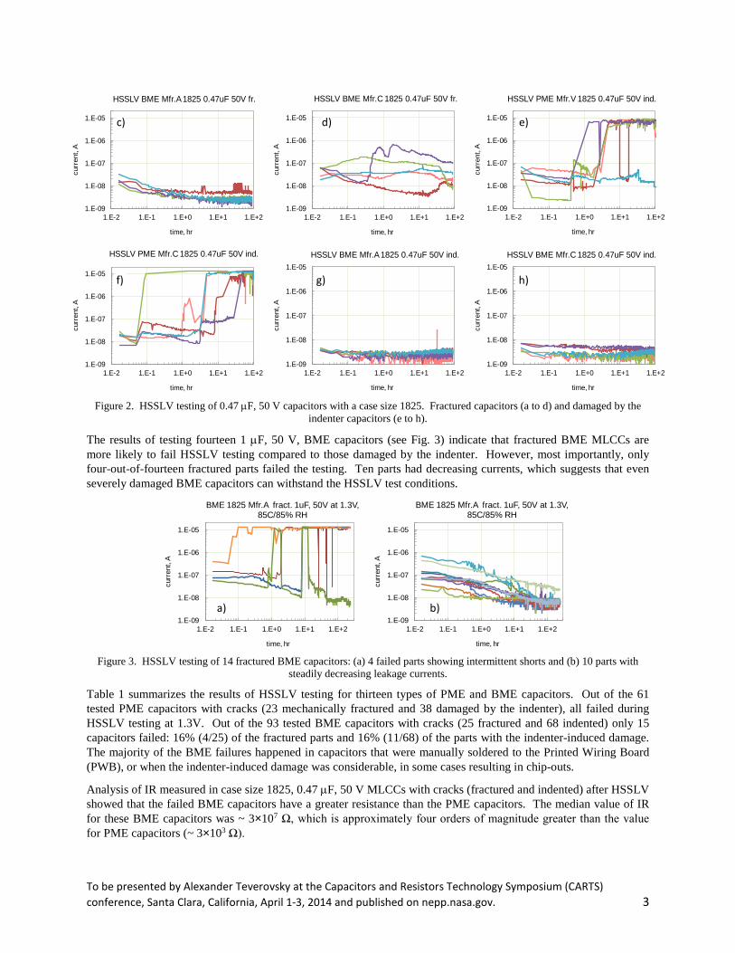
Figure 2. HSSLV testing of 0.47 µF, 50 V capacitors with a case size 1825. Fractured capacitors (a to d) and damaged by the
indenter capacitors (e to h).
The results of testing fourteen 1 µF, 50 V, BME capacitors (see Fig. 3) indicate that fractured BME MLCCs are more likely to fail HSSLV testing compared to those damaged by the indenter. However, most importantly, only four-out-of-fourteen fractured parts failed the testing. Ten parts had decreasing currents, which suggests that even severely damaged BME capacitors can withstand the HSSLV test conditions.
Figure 3. HSSLV testing of 14 fractured BME capacitors: (a) 4 failed parts showing intermittent shorts and (b) 10 parts with
steadily decreasing leakage currents.
Table 1 summarizes the results of HSSLV testing for thirteen types of PME and BME capacitors. Out of the 61 tested PME capacitors with cracks (23 mechanically fractured and 38 damaged by the indenter), all failed during HSSLV testing at 1.3V. Out of the 93 tested BME capacitors with cracks (25 fractured and 68 indented) only 15 capacitors failed: 16% (4/25) of the fractured parts and 16% (11/68) of the parts with the indenter-induced damage. The majority of the BME failures happened in capacitors that were manually soldered to the Printed Wiring Board (PWB), or when the indenter-induced damage was considerable, in some cases resulting in chip-outs.
Analysis of IR measured in case size 1825, 0.47 µF, 50 V MLCCs with cracks (fractured and indented) after HSSLV showed that the failed BME capacitors have a greater resistance than the PME capacitors. The median value of IR for these BME capacitors was ~ 3×10⁷ Ω, which is approximately four orders of magnitude greater than the value for PME capacitors (~ 3×10³ Ω).
1.E-09
1.E-08
1.E-07
1.E-06
1.E-05
1.E-2 1.E-1 1.E+0 1.E+1 1.E+2
curr
ent,
A
time, hr
HSSLV BME Mfr.A 1825 0.47uF 50V fr.
1.E-09
1.E-08
1.E-07
1.E-06
1.E-05
1.E-2 1.E-1 1.E+0 1.E+1 1.E+2
curr
ent,
A
time, hr
HSSLV BME Mfr.C 1825 0.47uF 50V fr.
1.E-09
1.E-08
1.E-07
1.E-06
1.E-05
1.E-2 1.E-1 1.E+0 1.E+1 1.E+2
curr
ent,
A
time, hr
HSSLV PME Mfr.V 1825 0.47uF 50V ind.
1.E-09
1.E-08
1.E-07
1.E-06
1.E-05
1.E-2 1.E-1 1.E+0 1.E+1 1.E+2
curr
ent,
A
time, hr
HSSLV PME Mfr.C 1825 0.47uF 50V ind.
1.E-09
1.E-08
1.E-07
1.E-06
1.E-05
1.E-2 1.E-1 1.E+0 1.E+1 1.E+2
curr
ent,
A
time, hr
HSSLV BME Mfr.A 1825 0.47uF 50V ind.
1.E-09
1.E-08
1.E-07
1.E-06
1.E-05
1.E-2 1.E-1 1.E+0 1.E+1 1.E+2
curr
ent,
A
time, hr
HSSLV BME Mfr.C 1825 0.47uF 50V ind.
1.E-09
1.E-08
1.E-07
1.E-06
1.E-05
1.E-2 1.E-1 1.E+0 1.E+1 1.E+2
curr
ent,
A
time, hr
BME 1825 Mfr.A fract. 1uF, 50V at 1.3V, 85C/85% RH
1.E-09
1.E-08
1.E-07
1.E-06
1.E-05
1.E-2 1.E-1 1.E+0 1.E+1 1.E+2
curr
ent,
A
time, hr
BME 1825 Mfr.A fract. 1uF, 50V at 1.3V, 85C/85% RH
a) b)
d) e)
f) g) h)
c)
To be presented by Alexander Teverovsky at the Capacitors and Resistors Technology Symposium (CARTS) conference, Santa Clara, California, April 1-3, 2014 and published on nepp.nasa.gov. 3

Table 1. HSSLV test results
# Part Mfr. Electrode damage F/QTY
1 2220, 1 µF, 50V A PME indenter 5/5 fracture 4/4
2 1825, 1 µF, 50V A BME indenter 0/14 fracture 4/15
3 1825, 1 µF, 50V C BME indenter 0/4
4 1825, 0.1 µF, 100V P PME indenter 5/5 fracture 4/4
5 1825, 0.47 µF, 50V C PME indenter 14/14 fracture 5/5
6 1825, 0.1 µF, 100V C PME fracture 5/5 7 1206, 10 µF, 16V M BME Indenter 1/6 8 1206, 22 µF, 6.3V M BME Indenter 1/7 9 1206, 4.7 µF, 25V C BME indenter 1/6
10 1210, 10 µF, 25V M BME indenter 0/9
11 1825, 0.47 µF, 50V V PME Indenter 14/14 fracture 5/5
12 1825, 0.47 µF, 50V C BME Indenter 5/14 fracture 0/5
13 1825, 0.47 µF, 50V A BME indenter 3/14 fracture 0/5
Effect of voltage In order to assess the effect of voltage on humidity testing, two groups of case size 1825, 1 µF, 50 V BME capacitors from Mfr. A and Mfr. C were tested by step stress testing at 22 °C and 85% RH with 100-hour steps. The voltage level varied between 1.3 V, 5 V, 15 V, 50 V, and 100 V. Each group contained four fractured capacitors and one reference sample. The results of these tests are shown in Fig. 4. At 1.3 V, none of the parts failed. Two parts failed during 5 V testing, one more during 15 V testing, and another two samples failed during 100 hr testing at 50 V. After 100 hours of testing at 100 V, all capacitors from Mfr. C failed catastrophically (currents exceeded 10 µA), whereas half of the fractured capacitors from Mfr. A did not fail the 1 µA criteria. Although these capacitors did not fail during 100 hours at 100 V, their currents started degrading after 10 to 50 hours and increased substantially by the end of testing.
The difference in the behavior of fractured capacitors from Mfr.A and C is most likely due to the difference in the dielectric thickness. The capacitors from Mfr. A have almost twice the dielectric thickness than the capacitors from Mfr. C.
1.E-10
1.E-09
1.E-08
1.E-07
1.E-06
1.E-05
1.E-3 1.E-2 1.E-1 1.E+0 1.E+1 1.E+2
curr
ent,
A
time, hr
1825 1uF 50V fr. at 1.3V 22C 85%RH
1.E-10
1.E-09
1.E-08
1.E-07
1.E-06
1.E-05
1.E-3 1.E-2 1.E-1 1.E+0 1.E+1 1.E+2
curr
ent,
A
time, hr
1825 1uF 50V fr. at 5V 22C 85%RH
1.E-10
1.E-09
1.E-08
1.E-07
1.E-06
1.E-05
1.E-3 1.E-2 1.E-1 1.E+0 1.E+1 1.E+2
curr
ent,
A
time, hr
1825 1uF 50V fr. at 15V 22C 85%RH
c a) b) c)
To be presented by Alexander Teverovsky at the Capacitors and Resistors Technology Symposium (CARTS) conference, Santa Clara, California, April 1-3, 2014 and published on nepp.nasa.gov. 4

Figure 4. Leakage currents in fractured 1825, BME, 1 µF, 50 V, capacitors (5 samples from Mfr. A and 5 samples from Mfr. C)
at room temperature and 85% RH, tested for 100 hours each at 1.3 V (a), 5 V (b), 15 V (c), 50 V (d), and 100 V (e).
The results of testing at different voltages clearly indicate that high voltages are much more effective for revealing cracks in BME capacitors. Further, this conclusion was confirmed by additional testing of fractured 1 µF, 50 V capacitors from Mfr. A, which performed relatively well in humid environments. During this testing, four fractured capacitors and one reference sample were tested at 22 °C and 85% RH at 5 V, and then at 15 V (see Fig. 5). None of the parts failed during 100 hours at 5 V, but all showed some increase in leakage currents after ~10 hours of testing. All fractured capacitors failed eventually within 100 hours at 15 V.
Figure 5. Test results for fractured BME, 1 µF, 50V, case size 1825 capacitors at 85% RH, 5V (a) and 15V (b).
Ten fractured capacitors from Mfr. A (1 µF, 50 V) that had passed the standard HSSLV testing at 85 °C, 85% RH and 1.3 V, were subsequently tested at 85 °C, 85% RH and 5 V. The results of this test are shown in Fig. 6. Although during 200 hours of testing at 5 V, only six-out-of-10 parts exceeded the 1 µΑ failure criteria, all parts had elevated and unstable leakage currents.
Figure 6. Temperature-Humidity-Bias (THB) testing of fractured BME, 1 µF, 50 V, 1825 capacitors at 85 °C, 85% RH, at 5 V.
Nine damaged by the indenter and one reference 10 µF, 25 V capacitors from Mfr. M with case size 1210, were subjected to standard HSSLV conditions, and subsequently to THB testing at 15 V. Results of these tests are shown in Fig. 7. No failures or substantial degradation was observed during standard HSSLV testing; however, all parts manifested increasing leakage currents and failed within approximately three hours of testing at 15 V. After 100
1.E-10
1.E-09
1.E-08
1.E-07
1.E-06
1.E-05
1.E-3 1.E-2 1.E-1 1.E+0 1.E+1 1.E+2
curr
ent,
A
time, hr
1825 1uF 50V fr. at 50V 22C 85%RH
1.E-09
1.E-08
1.E-07
1.E-06
1.E-05
1.E-3 1.E-2 1.E-1 1.E+0 1.E+1 1.E+2
curr
ent,
A
time, hr
1825 1uF 50V fr. at 100V 22C 85%RH
1.E-10
1.E-09
1.E-08
1.E-07
1.E-06
1.E-05
1.E-2 1.E-1 1.E+0 1.E+1 1.E+2
curr
ent,
A
time, hr
1825 BME 1uF 50V Mfr.A at 5V 85%RH 22C
referenceSN11SN12SN13SN14
1.E-10
1.E-09
1.E-08
1.E-07
1.E-06
1.E-05
1.E-04
1.E-2 1.E-1 1.E+0 1.E+1 1.E+2 1.E+3
curr
ent,
A
time, hr
1825 BME 1uF 50V Mfr.A at 15V 85%RH 22C
refSN11SN12SN13SN14
1.E-09
1.E-08
1.E-07
1.E-06
1.E-05
1.E-04
1.E-2 1.E-1 1.E+0 1.E+1 1.E+2
curr
ent,
A
time, hr
BME 1825 Mfr.A fract. 1uF, 50V at 5V, 85C/85% RH. Passed 1.3V
a) b)
e) d)
To be presented by Alexander Teverovsky at the Capacitors and Resistors Technology Symposium (CARTS) conference, Santa Clara, California, April 1-3, 2014 and published on nepp.nasa.gov. 5
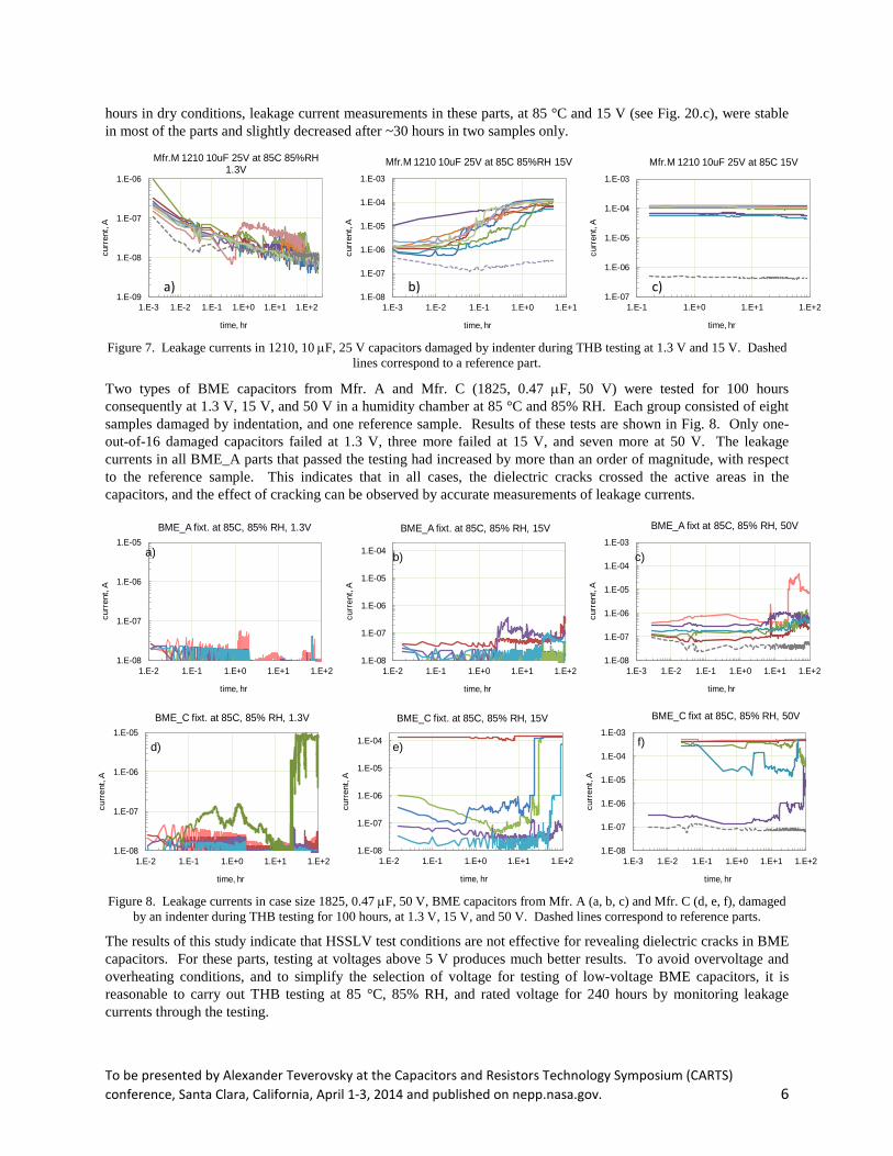
hours in dry conditions, leakage current measurements in these parts, at 85 °C and 15 V (see Fig. 20.c), were stable in most of the parts and slightly decreased after ~30 hours in two samples only.
Figure 7. Leakage currents in 1210, 10 µF, 25 V capacitors damaged by indenter during THB testing at 1.3 V and 15 V. Dashed
lines correspond to a reference part.
Two types of BME capacitors from Mfr. A and Mfr. C (1825, 0.47 µF, 50 V) were tested for 100 hours consequently at 1.3 V, 15 V, and 50 V in a humidity chamber at 85 °C and 85% RH. Each group consisted of eight samples damaged by indentation, and one reference sample. Results of these tests are shown in Fig. 8. Only one-out-of-16 damaged capacitors failed at 1.3 V, three more failed at 15 V, and seven more at 50 V. The leakage currents in all BME_A parts that passed the testing had increased by more than an order of magnitude, with respect to the reference sample. This indicates that in all cases, the dielectric cracks crossed the active areas in the capacitors, and the effect of cracking can be observed by accurate measurements of leakage currents.
Figure 8. Leakage currents in case size 1825, 0.47 µF, 50 V, BME capacitors from Mfr. A (a, b, c) and Mfr. C (d, e, f), damaged
by an indenter during THB testing for 100 hours, at 1.3 V, 15 V, and 50 V. Dashed lines correspond to reference parts.
The results of this study indicate that HSSLV test conditions are not effective for revealing dielectric cracks in BME capacitors. For these parts, testing at voltages above 5 V produces much better results. To avoid overvoltage and overheating conditions, and to simplify the selection of voltage for testing of low-voltage BME capacitors, it is reasonable to carry out THB testing at 85 °C, 85% RH, and rated voltage for 240 hours by monitoring leakage currents through the testing.
1.E-09
1.E-08
1.E-07
1.E-06
1.E-3 1.E-2 1.E-1 1.E+0 1.E+1 1.E+2
curr
ent,
A
time, hr
Mfr.M 1210 10uF 25V at 85C 85%RH 1.3V
1.E-08
1.E-07
1.E-06
1.E-05
1.E-04
1.E-03
1.E-3 1.E-2 1.E-1 1.E+0 1.E+1
curr
ent,
A
time, hr
Mfr.M 1210 10uF 25V at 85C 85%RH 15V
1.E-07
1.E-06
1.E-05
1.E-04
1.E-03
1.E-1 1.E+0 1.E+1 1.E+2
curr
ent,
A
time, hr
Mfr.M 1210 10uF 25V at 85C 15V
1.E-08
1.E-07
1.E-06
1.E-05
1.E-2 1.E-1 1.E+0 1.E+1 1.E+2
curr
ent,
A
time, hr
BME_A fixt. at 85C, 85% RH, 1.3V
1.E-08
1.E-07
1.E-06
1.E-05
1.E-04
1.E-2 1.E-1 1.E+0 1.E+1 1.E+2
curr
ent,
A
time, hr
BME_A fixt. at 85C, 85% RH, 15V
1.E-08
1.E-07
1.E-06
1.E-05
1.E-04
1.E-03
1.E-3 1.E-2 1.E-1 1.E+0 1.E+1 1.E+2
curr
ent,
A
time, hr
BME_A fixt at 85C, 85% RH, 50V
1.E-08
1.E-07
1.E-06
1.E-05
1.E-2 1.E-1 1.E+0 1.E+1 1.E+2
curr
ent,
A
time, hr
BME_C fixt. at 85C, 85% RH, 1.3V
1.E-08
1.E-07
1.E-06
1.E-05
1.E-04
1.E-2 1.E-1 1.E+0 1.E+1 1.E+2
curr
ent,
A
time, hr
BME_C fixt. at 85C, 85% RH, 15V
1.E-08
1.E-07
1.E-06
1.E-05
1.E-04
1.E-03
1.E-3 1.E-2 1.E-1 1.E+0 1.E+1 1.E+2
curr
ent,
A
time, hr
BME_C fixt at 85C, 85% RH, 50V
a) b) c)
a) b) c)
d) e) f)
To be presented by Alexander Teverovsky at the Capacitors and Resistors Technology Symposium (CARTS) conference, Santa Clara, California, April 1-3, 2014 and published on nepp.nasa.gov. 6

Results of failure analysis After completing humidity testing, the surfaces of the fractured capacitors were analyzed using scanning electron microscopy (SEM) and the elemental compositions were determined using energy dispersive X-ray spectroscopy (EDS). Figure 9 shows an example of this analysis for a PME capacitor (1825, 0.1 µF, 100 V) that was tested at 85% RH, 22 °C, 5 V and failed after 20 hours of testing. The results clearly indicate the presence of silver on the surface between the metal electrodes. Contrary to the observations in [6] where multiple silver dendrites were observed on the surface of the cross-sectioned and polished samples, no dendrites were detected on the surface of fractioned samples in this study.
Figure 9. An SEM view (a) and EDS mapping (b) of a fractured PME, case size 1825, 0.1 µF, 100 V capacitor, after testing at 22
°C, 85% RH, and 5 V.
Bulbous, amorphous formations (see Fig. 10) were observed on the surface of the BME capacitors (1 µF, 50 V) that failed after 300 hours at 85% RH, 22 °C, 15 V. These formations were similar to those observed previously on the surfaces of the cross-sectioned samples [6], and contained nickel, carbon, and oxygen in their composition. The formations appeared white in SEM images, indicating that they had poor electrical conductivity. These compositions formed mostly on the anode electrodes of the capacitors.
Figure 10. SEM images and EDS mapping of a Mfr. A, case size 1825, 1 µF, 50 V, fractured BME capacitor, after testing at 22
°C, 85% RH, and 15 V for 300 hours.
Dendrite-like accumulations of silver and palladium were observed on the surface of PME capacitors (1825, 0.47 µF, 50 V) after HSSLV testing (see Fig. 11.a). However, the presence of debris, generated during the fracturing process, obscured clear observation of the formations. Familiar bulbous formations, comprised of nickel, carbon, and oxygen, were discovered on the BME capacitors that were tested in parallel with these PME capacitors (see Fig. 11.b). However, these BME capacitors were exposed to 15 V during humidity testing.
a) b)
To be presented by Alexander Teverovsky at the Capacitors and Resistors Technology Symposium (CARTS) conference, Santa Clara, California, April 1-3, 2014 and published on nepp.nasa.gov. 7
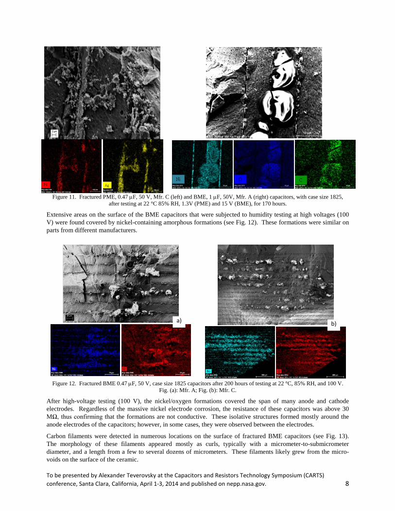
Figure 11. Fractured PME, 0.47 µF, 50 V, Mfr. C (left) and BME, 1 µF, 50V, Mfr. A (right) capacitors, with case size 1825,
after testing at 22 °C 85% RH, 1.3V (PME) and 15 V (BME), for 170 hours.
Extensive areas on the surface of the BME capacitors that were subjected to humidity testing at high voltages (100 V) were found covered by nickel-containing amorphous formations (see Fig. 12). These formations were similar on parts from different manufacturers.
Figure 12. Fractured BME 0.47 µF, 50 V, case size 1825 capacitors after 200 hours of testing at 22 °C, 85% RH, and 100 V.
Fig. (a): Mfr. A; Fig. (b): Mfr. C.
After high-voltage testing (100 V), the nickel/oxygen formations covered the span of many anode and cathode electrodes. Regardless of the massive nickel electrode corrosion, the resistance of these capacitors was above 30 MΩ, thus confirming that the formations are not conductive. These isolative structures formed mostly around the anode electrodes of the capacitors; however, in some cases, they were observed between the electrodes.
Carbon filaments were detected in numerous locations on the surface of fractured BME capacitors (see Fig. 13). The morphology of these filaments appeared mostly as curls, typically with a micrometer-to-submicrometer diameter, and a length from a few to several dozens of micrometers. These filaments likely grew from the micro-voids on the surface of the ceramic.
a) b)
To be presented by Alexander Teverovsky at the Capacitors and Resistors Technology Symposium (CARTS) conference, Santa Clara, California, April 1-3, 2014 and published on nepp.nasa.gov. 8

Figure 13. SEM views (left) and EDS maps (right) of areas with carbon filaments on the surface of a fractured BME, case size
1825, 0.47 µF, 50 V capacitor after HSSLV testing followed by 200 hours of testing at 22 °C, 85% RH, and 100V.
Fig.14 shows another example of the filamentous carbon structures that were detected also on the surface of samples from another manufacturer. This suggests that the growth of the carbon curls is a common phenomenon for fractured BME capacitors that are exposed to high humidity conditions.
Figure 14. Examples of carbon filaments on the surface of BME capacitors.
Discussion The most important result obtained from this study is the discovery that the failure modes and the probability of failure for PME and BME capacitors with dielectric cracks are different. At a similar level of cracking, BME capacitors have a much lower probability of failure than PME capacitors. In addition, the leakage currents in BME capacitors typically degrade relatively slowly, and require higher voltages than PME capacitors. These results can be explained by the different electro-chemical behavior of the nickel and silver/palladium electrodes in humid environments.
To be presented by Alexander Teverovsky at the Capacitors and Resistors Technology Symposium (CARTS) conference, Santa Clara, California, April 1-3, 2014 and published on nepp.nasa.gov. 9

Although silver dendrites were not found on the surface of the fractured PME capacitors after humidity testing, the results clearly show the electrochemical migration of silver across the dielectric. It remains quite possible that tiny silver or silver/palladium dendrites are present on the surface of the fractured capacitors, similar to those observed on the surface of the cross-sectioned samples in our earlier study [6]. However, the detection of the dendrites is extremely difficult on the uneven surface of fractured ceramic. Considering that the specific resistance of the silver/palladium alloy is low, ~ 3×10⁻⁵ Ohm-cm, a thin wire with a diameter of 1 µm and a length of 25 µm, would have a resistance of only ~ 5 Ω. Certainly, such a wire would be extremely difficult to detect on the rough surface of a fractured MLCC.
Even if the formation of silver dendrites does not occur, deposits of silver or silver oxide would substantially increase the electrical conductance. Depending on the oxygen content, the resistivity of silver oxide varies from 10-5 to 10-3 Ohm-cm [7]. For example, if a crack with a width of 100 µm extends through a MLCC with 10 µm electrode spacing, even a very thin, 10 nm thick, silver oxide film would reduce the capacitor’s resistance to a range that extends from only 1 Ω to 100 Ω. This example shows that even tiny areas of silver oxide on the surface of cracks in PME capacitors can cause substantial degradation of the IR and lead to failures. Drying capacitors that had failed did not result in a substantial reduction of the leakage currents. This is because the excessive leakage was due to deposits of silver or conductive silver oxides, rather than to the presence of adsorbed moisture.
Analysis of the surface of fractured BME capacitors revealed evidence of the electrochemical migration of nickel at voltages as low as 1.3 V. However, similar to what was observed on the surface of the cross-sectioned capacitors after HSSLV testing in our previous work [6], nickel formed amorphous, bulbous deposits on the anode electrodes. These deposits covered large areas of the capacitors and were mostly comprised of nickel oxide, with the addition of some carbon. The formation of these deposits can be explained by the anodic dissolution of Ni+ ions from the electrodes, which then form complex cations through reactions with water and CO2, and subsequently lead to the reduction of the cations at the anode. As a result, agglomerates of nickel oxides (NiO) and nickel carbonates (NiCO3) are formed around anode electrodes of the capacitor.
Pure stoichiometric NiO crystals are perfect insulators with a specific resistivity of ~ 1013 Ohm-cm [8]. However, doped, or non-stoichiometric films with excess oxygen or less oxygen might have a lower resistivity, in the range from 10 to 106 Ohm-cm. In the example considered above for a PME capacitor, at this range of resistivity, the IR for a BME capacitor would have a value from 108 Ω to 1011 Ω. Most likely, water that is absorbed in the nickel carbonate formations increases the conductivity on the compositions. Although slowly, this water can be removed during long-term baking at 85 °C or 125 °C, resulting in increasing the IR above 30 MΩ.
Results of this study indicate that electrochemical processes occurring in BME capacitors with cracks at higher voltages happen more quickly and result in the formation of deposits with a lower resistivity product. It is also possible that the extensive growth of Ni/O/C compositions at high voltages results in further development and propagation of the cracks. For this reason, humidity testing of BME capacitors is recommended at higher voltages than for PME capacitors.
Although less extensively than for PME capacitors, short circuit failures occurred also in BME capacitors (IR in the kilo-Ohm range). These failures mostly occurred in fractured capacitors, and the likely cause of these failures is the migration of ions that were generated by the anodic dissolution of metals used in the terminations (copper, tin, lead). It has been shown in our previous work [6] that these ions are highly susceptible to electromigration, and in the presence of a water layer on the surface of the MLCCs, form dendrites at the edges of the electrodes. Dendrites on the surface of the BME capacitors were not observed; however, in some cases after humidity testing, traces of lead and tin were detected through EDS analysis near the nickel electrodes. The presence of both tin and lead were detected during EDS mapping on capacitors from Mfr. C (1825, 0.47 µF, 50 V), whereas only tin was detected on similar capacitors from Mfr. V. This corresponds to the tin/lead outer finish in the first case, and to the pure tin finish in the second case, which suggests the possibility of tin and/or lead dendrite formation. When dendrites grow to short the electrodes of a capacitor, they can blow at high voltages, resulting in intermittent failures.
Additional tests showed that BME capacitors with larger cover plates have a lower probability of failure in cases where cracks originate from the surface of the part. However, cracks in the active areas of capacitors with thinner dielectric layers have a much more detrimental effect on the IR degradation and failures.
To be presented by Alexander Teverovsky at the Capacitors and Resistors Technology Symposium (CARTS) conference, Santa Clara, California, April 1-3, 2014 and published on nepp.nasa.gov. 10
A separate set of experiments showed that manual soldering of MLCCs that contain preexisting cracks substantially increases the probability of failure. For case size 1825, 0.47 µF, 50 V, PME capacitors soldered onto a PWB, the median Time to Failure (TTF) decreases by approximately an order of magnitude in comparison to similar capacitors that were tested in a mechanical fixture. For similar BME capacitors, the difference in TTF between soldered and mounted groups of capacitors is more than three orders of magnitude.
In this study, we observed for the first time carbon filaments growing on the surface of fractured ceramic capacitors after testing at 85 °C and 85% RH. The filaments had a diameter of ~ 0.5 µm, a length that ranged from several to dozens of micrometers, and appeared to grow from the grains in multiple locations on the fractured surface of the BME capacitors. No similar formations were detected on the surface of the PME capacitors. Carbon filaments are known to grow at high temperatures on catalyst surfaces and on some metals, when heated in the presence of carbon-containing gases [9-10]. The metals that can grow carbon filaments include iron, cobalt, and nickel. However, nickel causes the fastest rate of growth. Filamentous carbon is formed on small areas of polycrystalline metals that have small grain sizes, typically less than 0.5 µm. A common characteristic of all carbon filaments is that the metal particle, typically nickel, is found at the growing tip of the filament. It is assumed that the growth of carbon filaments occurs along with the decomposition of some hydrocarbons, and the carbon is transported by surface diffusion.
Neither the reason nor the significance of the carbon filament growth on the surface of the cracked capacitors is yet clear, and requires additional analysis. However, the major ingredients for the filaments formation are present on the MLCCs. The presence of carbon is most likely due to the left-over remnants from the binder burning process, and the catalytic metal (Ni) is used as a material for electrodes. The ceramic is highly mechanically stressed, and diffusion processes are enhanced substantially by the presence of grains and micropores. Also, the surface of the fractured ceramic capacitors is likely very chemically active, which can be confirmed by the observation of hydrocerussite-like, Pb3(OH)2(CO3)2, platelets [6]. These formations occurred due to the reactions of lead, water and carbon dioxide on the surface.
The main focus of this study was to reveal the common features of degradation in MLCCs with cracks and determine the specific differences between PME and BME capacitors. However, some data confirmed our previous observation [11] that the susceptibility of capacitors to cracking might be lot-specific. For example, manual soldering resulted in two-out-of-seven failures in BME_A capacitors, whereas none of the six BME_C capacitors failed. Note that in the majority of the other tests, the BME_C capacitors with cracks behaved somewhat worse than the cracked BME_A capacitors.
Conclusion 1. All tested PME capacitors with cracks failed standard HSSLV testing at 85 °C, 85% RH, and 1.3 V. However,
this testing resulted in only ~ 16% of failures for the fractured BME capacitors. The majority of BME failures happened in capacitors with extensive cracking close to the area of terminal metallization. The post-testing values of IR are greater in BME capacitors than in PME capacitors by almost four orders of magnitude.
2. In humid environments the rate of leakage current degradation in BME capacitors with cracks increases with the applied voltage. Minimal to no increase in leakage currents is observed at 1.3 V, degradation becomes noticeable at 5 V, and is clearly seen at 15 V and greater. Instead of HSSLV testing that is used for PME capacitors, THB testing for 240 hours at 85 °C, 85% RH, and rated voltages is recommended for BME capacitors.
3. Degradation and failures during humidity testing of PME and BME MLCCs with cracks in both cases are due to anodic dissolution and electrochemical migration of the electrode or termination materials, which can occur even at low voltages (~1.3 V). However, a substantial difference in their behavior and the probability of failure are due to the difference in the products formed during migration processes. In PME capacitors, formation of conductive silver dendrites or silver oxide deposits results in short-circuits between the electrodes, whereas in BME capacitors, highly resistive nickel/carbon/oxygen compositions are formed.
4. The fractured surface of BME MLCCs is chemically active and humid environments can facilitate the formation of nickel carbohydrate compositions at the anode electrodes, lead carbohydrates (hydrocerussite-like platelets), or carbon filaments on the surface of the ceramic. Formation of these carbon filaments was observed for the first
To be presented by Alexander Teverovsky at the Capacitors and Resistors Technology Symposium (CARTS) conference, Santa Clara, California, April 1-3, 2014 and published on nepp.nasa.gov. 11
time, and their origin, significance for reliability, and specific conditions of growth require more study and analysis.
Acknowledgment This work was sponsored by the NASA Electronic Parts and Packaging (NEPP) program. The authors are thankful to Michael Sampson, NEPP Program Manager, for support of this investigation, Bruce Meinhold, AS&D Group Lead, for a review and discussions.
References [1] H. C. Ling and A. M. Jackson, "Correlation of silver migration with temperature-humidity-bias (THB) failures in
multilayer ceramic capacitors," IEEE Transactions on Components, Hybrids, and Manufacturing Technology, vol. 12, pp. 130 - 137, 1989.
[2] T. Brennan, "Ceramic Capacitor Insulation Resistance Failures Accelerated by Low Voltage," IEEE transactions on electron devices, vol. ED-26, pp. 102-108, 1979.
[3] K. Sato, et al., "Mechanism of Ceramic Capacitor Leakage Failures due to Low DC Stress," in Reliability Physics Symposium, 1980. 18th Annual, 1980, pp. 205-212.
[4] A. M. Holladay, "Unstable insulation resistance in ceramic capacitors " Proceedings of Capacitor Technologies, Applications and Reliability, NASA, pp. 27-31, 1981.
[5] M. Sampson, et al., "Humidity Steady State Low Voltage Testing of MLCCs (Based on NESC Technical Assessment Report)," in CARTS USA, Jacksonville, Fl, 2011.
[6] J. Herzberger and A. Teverovsky, "Dendrite growth in PME and BME ceramic capacitors," in CARTS International, Houston, TX, 2013, p. 3.3.
[7] U. Kumar Barik, et al., "Electrical and optical properties of reactive DC magnetron sputtered silver oxide thin films: role of oxygen," Thin Solid Films, vol. 429, pp. 129-134, 2003.
[8] P. S. Patil and L. D. Kadam, "Preparation and characterization of spray pyrolyzed nickel oxide (NiO) thin films," Applied Surface Science, vol. 199, pp. 211-221, 2002.
[9] R. T. K. Baker, "Catalytic growth of carbon filaments," Carbon, vol. 27, pp. 315-323, 1989. [10] R. T. Yang and J. P. Chen, "Mechanism of carbon filament growth on metal catalysts," Journal of Catalysis, vol. 115, pp.
52-64, 1989. [11] A. Teverovsky, "Thermal Shock Testing and Fracturing of MLCCs under Manual Soldering Conditions," IEEE
Transactions on Device and Materials Reliability vol. 12, pp. 413-419, 2012.
To be presented by Alexander Teverovsky at the Capacitors and Resistors Technology Symposium (CARTS) conference, Santa Clara, California, April 1-3, 2014 and published on nepp.nasa.gov. 12


