Embed Size (px)
Citation preview

Instruction Manual
*How to find the version of your instrument: page 47
Manfred WeberMetra Mess- und Frequenztechnik in Radebeul e.K.
Meissner Str. 58 - D-01445 RadebeulPhone +49-351-836 2191 Fax +49-351-836 2940
Email: [email protected] Internet: www.MMF.de
HumanVibration
MeterVM30-H
From Version 01.01.004.007*

The latest edition of this document can be found under:http://www.mmf.de/product_literature.htm
© Manfred Weber
Metra Meß- und Frequenztechnik in Radebeul e.K.
May/ 12 #193
Contents1. Purpose....................................................................................................................................12. The Instrument at a Glance.......................................................................................................13. Menus......................................................................................................................................24. Fundamentals of Human Vibration Measurement ...................................................................4
4.1. Introduction.......................................................................................................................44.2. EU Directive 2002/44/EC..................................................................................................4
5. Human Vibration Measurement with the VM30-H..................................................................75.1. Switching On and Connecting the Sensor .........................................................................75.2. Hand-Arm Vibration Measurement with the VM30-H......................................................8
5.2.1. Measuring Points for Hand-Arm Vibration ................................................................85.2.2. Settings on the VM30-H.............................................................................................95.2.3. Reporting of Measuring Results................................................................................10
5.3. Whole-Body Vibration Measurement with the VM30-H.................................................115.3.1. Measuring points for Whole-Body Vibration............................................................115.3.2. Settings at the VM30-H............................................................................................125.3.3. Evaluation of Health Risks........................................................................................145.3.4. Comfort Evaluation...................................................................................................155.3.5. Reporting of Measuring Results................................................................................15
6. Switching the Instrument On and Off.....................................................................................167. Sensor Input...........................................................................................................................168. Display...................................................................................................................................179. Signal Setup...........................................................................................................................18
9.1. Vibration Quantity...........................................................................................................189.2. Filters..............................................................................................................................18
9.2.1. Weighting Filters......................................................................................................189.2.1.1. Weighting Filter Wb ..........................................................................................189.2.1.2. Weighting Filter Wc ..........................................................................................199.2.1.3. Weighting Filter Wd...........................................................................................199.2.1.4. Weighting Filter We...........................................................................................209.2.1.5. Weighting Filter Wg...........................................................................................209.2.1.6. Weighting Filter Wh...........................................................................................219.2.1.7. Weighting Filter Wj...........................................................................................219.2.1.8. Weighting Filter Wk...........................................................................................229.2.1.9. Weighting Filter Wm..........................................................................................229.2.1.10. Combined Weighting Filters............................................................................23
9.2.2. Band-Pass Filters......................................................................................................239.3. Display Modes.................................................................................................................24
9.3.1. Running RMS...........................................................................................................249.3.2. Maximum Transient Vibration Value (MTVV)........................................................249.3.3. Interval RMS (A(T)).................................................................................................24

9.3.4. Estimated Vibration Dose Value (eVDV).................................................................259.3.5. Vibration Total Value (Ahv).....................................................................................269.3.6. Peak Value (PEAK)..................................................................................................269.3.7. Maximum Peak Value (PEAK↑)...............................................................................279.3.8. Crest Factor (CREST)...............................................................................................27
9.4. Saving User-Defined Setups............................................................................................279.5. Loading User-Defined Setups..........................................................................................28
10. Measuring Range and Autoranging......................................................................................2811. Overload Indication..............................................................................................................2912. Saving Measuring Results....................................................................................................29
12.1. Manual Recording by the SAVE Key............................................................................2912.2. Automatic Recording in the Data Logger Mode............................................................30
13. Data Transmission to the PC................................................................................................3113.1. Preparing the Import of Data into Excel........................................................................3113.2. Importing VM30-H Data with the Excel Macro ...........................................................3113.3. Calculation of the Daily Exposure Value A(8)..............................................................3313.4. Function of the Excel Macro ........................................................................................3613.5. Transmission to PC by a Terminal Program..................................................................37
14. Time and Date......................................................................................................................3815. Calibration and Function Check...........................................................................................39
15.1. Entering Transducer Sensitivities .................................................................................3915.2. Sensitivity Calibration by a Vibration Calibrator ..........................................................3915.3. Mechanical Calibration..................................................................................................4015.4. Electrical Calibration.....................................................................................................4015.5. Function Check..............................................................................................................43
16. Other Settings ......................................................................................................................4416.1. Beep Sound On / Off.....................................................................................................4416.2. Automatic Shut-Off Timer.............................................................................................4416.3. Battery Type..................................................................................................................4416.4. Factory Settings.............................................................................................................4416.5. Baud Rate......................................................................................................................44
17. Serial Interface.....................................................................................................................4418. Signal Output.......................................................................................................................4519. Power Supply.......................................................................................................................45
19.1. Battery Operation..........................................................................................................4519.2. External Supply.............................................................................................................46
20. Loading Default Settings......................................................................................................4721. Hardware Reset....................................................................................................................4722. Hardware and Firmware Versions .......................................................................................4723. Questions and Answers........................................................................................................4824. Technical Data.....................................................................................................................49

Appendix: WarrantyDeclaration of Conformity
1. PurposeThank you for choosing a vibration meter from Metra!The VM30-H was developed for the measurement of human vibrations. In addition, it is suited for many other fields of vibration measurement such as machine vibration, building vibration or quality control. The instrument can measure triaxial hand-arm vibration to EU directive 2002/44/EC based on ISO 5349 and whole-body vibration to ISO 2631. It conforms to the latest edition of ISO 8041 for measuring instrumentation for human vibration. Particular attention has been paid to simple operation, compact design and long battery operating time.
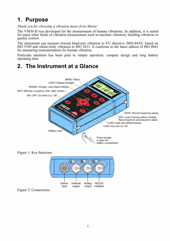
2. The Instrument at a Glance
Figure 1: Key functions
Figure 2: Connections
1
Sensorinput
Externalsupply
Analogoutput
RS-232interface
Battery cover
SAVE: Record measuring values
ESC: Leave menues without change,Reset maximum and long-term values
LOAD: Load user-defined setupsLOCK: Key lock on / off
MENU: SetupLIGHT: Display backlight
INFO: Memory occupancy, time, date, version
RANGE: Change / save signal settings
ON / OFF: On (hold 2 s) / Off
Press stronglyto open thebattery compartment

Figure 3: Battery compartment and reset button
3. Menus
2
MENU
1/8: Gain Gain Range X
Main Menu
Select time unit Log duration
3/8: Send data to PC
Manually by SAVE key with / without comment with / without time with / without date
Log interval
(password protected)
Gain Range Y Gain Range Z
by data logger2/8: Recording setup
Log file title
4/8: Erase memory
5/8: Time and date
6/8: Load defaults
7/8: SensorBy vibration calibrator
By transducer sensitivity
8/8: Device Settings 1/5: Beeper on / off
2/5: Shut-off timer
3/5: Battery type
4/5: Factory settings
5/5: Baud rate
Edit this sensor?Sensor selection
no
yesNominal sensitivity
110
mV/ms²
Ent
ry a
fter
sens
or
conn
ectio
n
Sensor name
X/Y/Z
Battery compartment
Reset

3
Signal Setup Menu
RANGEHuman VibrationAccelerationVelocityDisplacement
Selection of thevibration quantity
Filter Band filters and weighting filters forselected vibration quantity
Running RMS (1 s)Max. running RMSInterval RMSEstimated vibr. doseTotal vibration valuePeak value (1 s)Max. peak valueCrest factor
RMSMTVVA(T)eVDVAhvPEAKPEAKCREST
Enter Ahv k factors
Save settings? No
Yes
Factors kx, ky und kzfor Ahv only
Save as: Setup No. Save as setup number 0 to 9
Enter setup name Setup name20 characters

4. Fundamentals of Human Vibration Measurement 4.1. IntroductionVibrations acting on the human body are called human vibration. The main purpose of measuring human vibration is the prevention of health risks and the evaluation of comfort, for example in vehicles.Two categories are distinguished:• Hand-Arm Vibrations, which are induced via the hands into the body. They may cause,
for example, circulatory disorder, bone, joint or muscle diseases. • Whole-Body Vibrations, acting via the buttocks, the back and the feet of a sitting person,
the feet of a standing person or the back and the head of a recumbent person. Such vibrations may cause backache or damage to the spinal column.
Both types of human vibration are described in international standards:• ISO 5349 - Measurement and evaluation of human exposure to hand-transmitted vibration • ISO 2631 - Evaluation of human exposure to whole-body vibration • ISO 8041 - Human response to vibration. Measuring instrumentation • ISO 8662 - Hand-held portable power tools - Measurement of vibrations at the handle • ISO 6954 - Guidelines for the measurement, reporting and evaluation of vibration with
regard to habitability on passenger and merchant ships • ISO 10056 - Measurement and analysis of whole-body vibration to which passengers and
crew are exposed in railway vehicles • ISO 10326 - Laboratory method for evaluating vehicle seat vibration Practical advice for measurement and evaluation of human vibration can be found in VDI 2057.The subject of human vibration has gained particular importance in Europe since the directive 2002/44/EC came into effect. It specifies the duties of employers with regard to workers protection.
4.2. EU Directive 2002/44/ECThe following text is an abstract of Directive 2002/44/EC of the European Parliament and of the Council dated June 25 2002. The complete text can be downloaded fromhttp://eur-lex.europa.eu/The directive lays down minimum requirements for the protection of workers from the risks arising from vibrations. Manufacturers of machines and employers should make an adjustment regarding risks related to exposure to vibration. The directive lays down the following limit values:
4
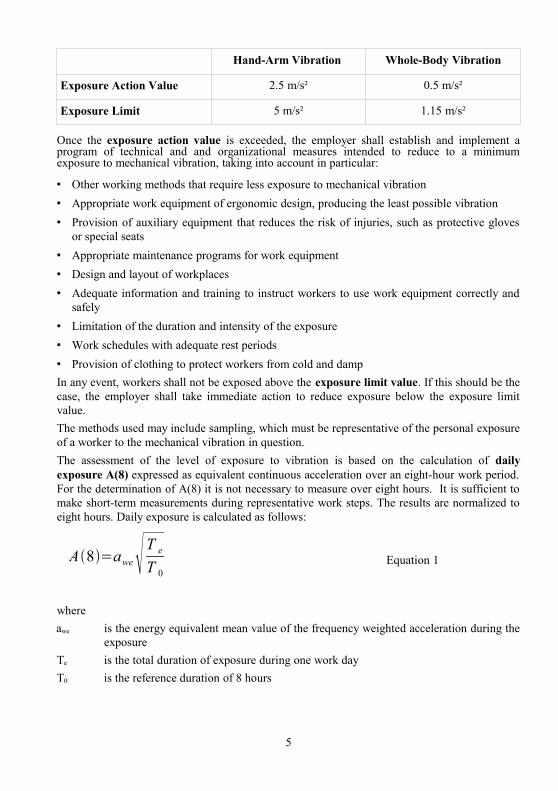
Hand-Arm Vibration Whole-Body Vibration
Exposure Action Value 2.5 m/s² 0.5 m/s²
Exposure Limit 5 m/s² 1.15 m/s²
Once the exposure action value is exceeded, the employer shall establish and implement a program of technical and and organizational measures intended to reduce to a minimum exposure to mechanical vibration, taking into account in particular:
• Other working methods that require less exposure to mechanical vibration• Appropriate work equipment of ergonomic design, producing the least possible vibration • Provision of auxiliary equipment that reduces the risk of injuries, such as protective gloves
or special seats• Appropriate maintenance programs for work equipment• Design and layout of workplaces• Adequate information and training to instruct workers to use work equipment correctly and
safely• Limitation of the duration and intensity of the exposure• Work schedules with adequate rest periods• Provision of clothing to protect workers from cold and dampIn any event, workers shall not be exposed above the exposure limit value. If this should be the case, the employer shall take immediate action to reduce exposure below the exposure limit value.The methods used may include sampling, which must be representative of the personal exposure of a worker to the mechanical vibration in question.The assessment of the level of exposure to vibration is based on the calculation of daily exposure A(8) expressed as equivalent continuous acceleration over an eight-hour work period. For the determination of A(8) it is not necessary to measure over eight hours. It is sufficient to make short-term measurements during representative work steps. The results are normalized to eight hours. Daily exposure is calculated as follows:
Equation 1
whereawe is the energy equivalent mean value of the frequency weighted acceleration during the
exposure Te is the total duration of exposure during one work dayT0 is the reference duration of 8 hours
5
A8=awe T e
T 0
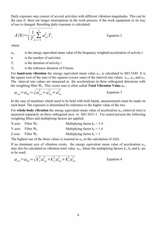
Daily exposure may consist of several activities with different vibration magnitudes. This can be the case if there are longer interruptions in the work process, if the work equipment or its way of use is changed. Resulting daily exposure is calculated:
A8= 1T 0
∑i=1
n
awi2 T i Equation 2
where
awi is the energy equivalent mean value of the frequency weighted acceleration of activity in is the number of activitiesTi is the duration of activity iT0 is the reference duration of 8 hoursFor hand-arm vibration the energy equivalent mean value awe is calculated to ISO 5349. It is the square root of the sum of the squares (vector sum) of the interval rms values awx, awy and awz.
The interval rms values are measured as the accelerations in three orthogonal directions with the weighting filter Wh. This vector sum is often called Total Vibration Value ahv :
awe=ahv=awx2 awy
2 awz2 Equation 3
In the case of machines which need to be held with both hands, measurements must be made on each hand. The exposure is determined by reference to the higher value of the two. For whole-body vibration the energy equivalent mean value of acceleration awe (interval rms) is measured separately on three orthogonal axes to ISO 2631-1. For seated persons the following weighting filters and multiplying factors are applied: X axis: Filter Wd Multiplying factor kx = 1.4Y axis: Filter Wd Multiplying factor ky = 1.4Z axis: Filter Wk Multiplying factor ky = 1The highest one of the three values is inserted as awe in the calculation of A(8).If no dominant axis of vibration exists, the energy equivalent mean value of acceleration awe
may also be calculated as vibration total value ahv, where the multiplying factors kx, ky and kz are to be used:
awe=ahv=k x2 awx
2 k y2 awy
2 k z2 awz
2 Equation 4
6

5. Human Vibration Measurement with the VM30-H5.1. Switching On and Connecting the Sensor Switch on the VM30-H by pressing the ON/OFF key for at least two seconds (compare p. 16).Plug in the sensor cable or unplug it shortly to activate the sensor detection. Select the connected sensor (hand-arm or whole-body) using the ▲▼ keys. If the VM30-H was calibrated already with the selected sensor, you may answer the question “Edit this sensor?” with “No”. Otherwise select “Yes”, choose the nominal transducer sensitivity (1 or 10 mV/m/s-2) and enter in the menu “By transducer sensitivity” the sensitivities from the supplied calibration certificate for X, Y and Z direction. Numbers can be changed by the ◄▲▼► keys. Confirm each entry with OK and leave the menu with ESC.The sensitivities of both sensor types remain stored in the instrument (see p. 39). They must not be entered again if the sensor is changed.
Figure 4: Sensors for hand-arm and whole-body vibration
7

5.2. Hand-Arm Vibration Measurement with the VM30-HThis section will give you basic instructions for the measurement and evaluation of hand-arm vibrations based on the standard ISO 5349 and the guideline VDI 2057, Part 2. Please consult the original documents for detailed explanations.
5.2.1. Measuring Points for Hand-Arm Vibration The sensors should be attached as close as possible to the place of entry into the hand, however, they must not interfere with the work process. Measurement shall be performed with the same hand pressure force as used under normal operating conditions.Since most machine tool handles do not provide surfaces for the adhesive or screw attachment of sensors, Metra offers some mounting accessories for curved surfaces.
Figure 5: Mounting accessories for hand-arm vibrations models 140 and 142
The adapter model 140 is attached with a plastic cable strap. Model 142 is pressed onto the handle by the hand.
Very important is a tight contact between sensor and machine. Any motion of the sensor would distort the measurement.
Figure 6 shows the axis directions for the attachment of the sensor at the handle. For cylindric handles the Y direction point in the direction of the handle axis. The Z axis is approximately the extension of the third metacarpal bone.
8
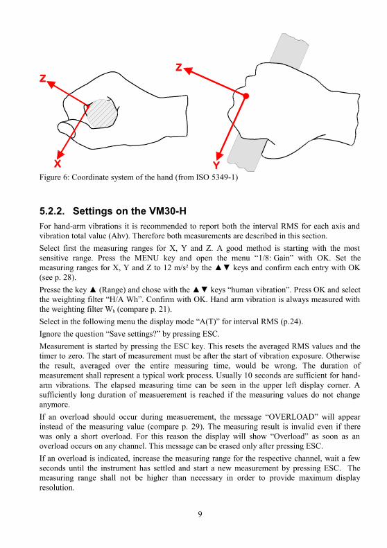
5.2.2. Settings on the VM30-HFor hand-arm vibrations it is recommended to report both the interval RMS for each axis and vibration total value (Ahv). Therefore both measurements are described in this section.Select first the measuring ranges for X, Y and Z. A good method is starting with the most sensitive range. Press the MENU key and open the menu “1/8: Gain” with OK. Set the measuring ranges for X, Y and Z to 12 m/s² by the ▲▼ keys and confirm each entry with OK (see p. 28).Presse the key ▲ (Range) and chose with the ▲▼ keys “human vibration”. Press OK and select the weighting filter “H/A Wh”. Confirm with OK. Hand arm vibration is always measured with the weighting filter Wh (compare p. 21).Select in the following menu the display mode “A(T)” for interval RMS (p.24).Ignore the question “Save settings?” by pressing ESC. Measurement is started by pressing the ESC key. This resets the averaged RMS values and the timer to zero. The start of measurement must be after the start of vibration exposure. Otherwise the result, averaged over the entire measuring time, would be wrong. The duration of measurement shall represent a typical work process. Usually 10 seconds are sufficient for hand-arm vibrations. The elapsed measuring time can be seen in the upper left display corner. A sufficiently long duration of measuerement is reached if the measuring values do not change anymore.If an overload should occur during measuerement, the message “OVERLOAD” will appear instead of the measuring value (compare p. 29). The measuring result is invalid even if there was only a short overload. For this reason the display will show “Overload” as soon as an overload occurs on any channel. This message can be erased only after pressing ESC. If an overload is indicated, increase the measuring range for the respective channel, wait a few seconds until the instrument has settled and start a new measurement by pressing ESC. The measuring range shall not be higher than necessary in order to provide maximum display resolution.
9
Figure 6: Coordinate system of the hand (from ISO 5349-1)

After a sufficient duration of measurement you may save the result by pressing SAVE. The vibration exposure must persist in the moment of saving. Please make sure that the instrument is in the manual save mode. If necessary, select in the menu “2/8: Recording setup” the mode “manually by SAVE key”. Otherwise the data logger will start after the SAVE key. You may also choose whether you like to save date and the time and a 20 characters comment with the result. A comment text can be entered with the ◄▲▼► keys and OK.
For the measurement of vibration total value Ahv press again the ▲ (Range) key, select “human vibration” and the weighting filter “H/A Wh”. Select the display mode “Ahv”. You will be asked for the multiplying factors kx, ky and kz. For hand-arm measurement they have the value “1.0” (see p. 26).The instrument will display only one value Ahv, which is the vector sum of three axes. Start the measurement by ESC and measure approximately for the same time as for interval RMS.With the gain settings made before there should be no overload.Save the measurement with the SAVE key.If the vibration exposure consists of different sections, more than one measurements may be required.For the calculation of daily exposure A(8) and for reporting the results Metra provides an Excel sheet with direct data import from the serial interface. A description can be found on page 31.Notice: You may simplify the setup of the VM30-H by using pre-defined setups. Press the ▼ (LOAD) key to choose from 10 stored setups. In the original configuration setup no. 0 contains the settings for the interval RMS of hand-arm vibration and setup no. 1 for vibration total value (see p. 27).
5.2.3. Reporting of Measuring ResultsThe report to ISO 5349-2 should include the following information:• General information:
- Client- Purpose of measurement- Date - Name of operator- Name of evaluating person
• Environmental conditions:- Location- Temperature- Humidity- Noise
• Daily operating sequence for the activities under test:- Description of activities- Used machine and tools- Time flow of activities (work time, breaks)- Basis for the used exposure time (e.g. job norm)
10
• Details of the vibration source:- Technical description of the machine- Type and Model- Age and maintenance condition- Weight of hand-held part or tool- Vibration reduction measures, if applicable- Type of handle- Automatic controls (e.g. torque control)- Power rating- Revolution speed, number of blows- Type of used tools
• Measuring equipment:- Instrument and sensor types, serial numbers- Traceable calibration- Date of last calibration- Results of function check
• Measuring conditions:- Measuring points and directions (sensor axes) with dimensional drawing- Mounting method of the sensor - Weight of the sensor- Operating condition- Arm and hand posture, left / right handed- Other data (e.g. hand pressure force)
• Measuring results:- Frequency weighted interval RMS values of acceleration awx, awy and awz. for three orthogonal directions, preferably for each activity - Measuring duration for each activity
• Results for daily exposure A(8):- Vibration total values for each activity - Duration Ti of vibration exposure for each activity - Partial exposure Ai(8) - Daily exposure A(8)- Assessment of measurement uncertainty
5.3. Whole-Body Vibration Measurement with the VM30-HThis section will give you basic instructions for the measurement and evaluation of whole-body vibrations based on the standard ISO 2631 and the guideline VDI 2057, Part 1. Please consult the original documents for detailed explanations. The described method is suitable for all vibrations acting on the human body. It is not suited for vibration containing occasional shocks and for impacts, like car crashes. Vibrations transmitted via the hands have been described separately in the previous section.
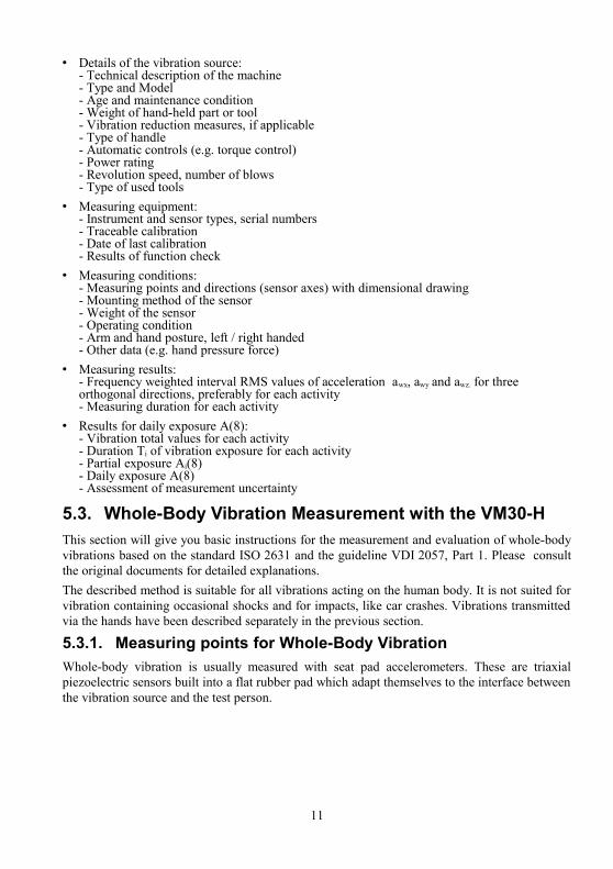
5.3.1. Measuring points for Whole-Body VibrationWhole-body vibration is usually measured with seat pad accelerometers. These are triaxial piezoelectric sensors built into a flat rubber pad which adapt themselves to the interface between the vibration source and the test person.
11
The following measuring points are suitable:
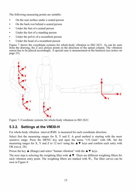
• On the seat surface under a seated person • On the back rest behind a seated person• Under the feet of a seated person• Under the feet of a standing person• Under the pelvis of a recumbent person • Under the head of a recumbent person Figure 7 shows the coordinate systems for whole-body vibration to ISO 2631. As can be seen from the drawing, the Z axis always points in the direction of the spinal column. The vibration sensor has to be placed accordingly. A special case is measurement at the backrest (see notice on page 23).
5.3.2. Settings at the VM30-HFor whole-body vibration interval RMS is measured for each coordinate direction.Select first the measuring ranges for X, Y and Z. A good method is starting with the most sensitive range. Press the MENU key and open the menu “1/8: Gain” with OK. Set the measuring ranges for X, Y and Z to 12 m/s² using the ▲▼ keys and confirm each entry with OK (see p. 28).Presse the key ▲ (Range) and select “human vibration” with the ▲▼ keys. The next step is selecting the weighting filter with ▲▼. There are different weighting filters for each vibration entry point. The weighting filters are marked with Wx. The filter curves can be seen in Figure 8.
12
Figure 7: Coordinate systems for whole-body vibration to ISO 2631
Z
YZ
Y
Z
X
YZ
XXY
X
Y
Z
X
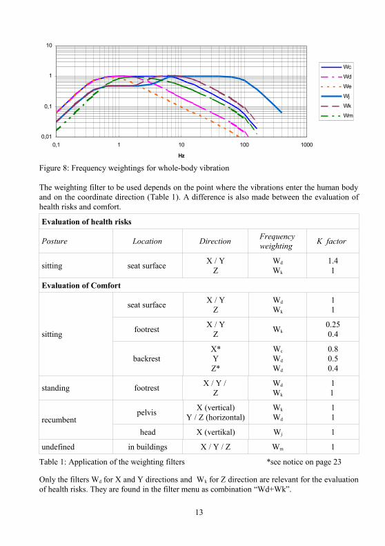
The weighting filter to be used depends on the point where the vibrations enter the human body and on the coordinate direction (Table 1). A difference is also made between the evaluation of health risks and comfort.
Evaluation of health risks
Posture Location Direction Frequency weighting K factor
sitting seat surface X / YZ
Wd
Wk
1.41
Evaluation of Comfort
sitting
seat surface X / YZ
Wd
Wk
11
footrest X / YZ Wk
0.250.4
backrest X*YZ*
Wc
Wd
Wd
0.80.50.4
standing footrest X / Y / Z
Wd
Wk
11
recumbentpelvis X (vertical)
Y / Z (horizontal)Wk
Wd
11
head X (vertikal) Wj 1
undefined in buildings X / Y / Z Wm 1
Table 1: Application of the weighting filters *see notice on page 23
Only the filters Wd for X and Y directions and Wk for Z direction are relevant for the evaluation of health risks. They are found in the filter menu as combination “Wd+Wk”.
13
Figure 8: Frequency weightings for whole-body vibration
0,01
0,1
1
10
0,1 1 10 100 1000
Hz
Wc
Wd
We
Wj
Wk
Wm

After this choose the display mode “A(T)” (interval RMS, p.24).
Ignore the question “Save settings?” by pressing ESC. Measurement is started by pressing the ESC key. This resets the averaged RMS values and the timer to zero. The start of measurement must be after the start of vibration exposure. Otherwise the result, averaged over the entire measuring period, would be wrong. The duration of measurement shall represent a typical exposure interval. It should be at least 2 minutes. The elapsed measuring time can be seen in the upper left display corner. A sufficiently long duration of measuerement is reached if the measuring values do not change anymore.If an overload should occur during measuerement, a message “OVERLOAD” will appear instead of the measuring value (compare p. 29). The measuring result is invalid even if there was only a short overload. For this reason the instrument will also display “Overload” in the upper line as soon as an overload occurs on any channel. This message can be erased only by pressing ESC. If an overload is indicated, increase the measuring range for the respective channel, wait a few seconds until the instrument has settled and start a new measurement by pressing ESC. The measuring range must not be higher than necessary in order to provide maximum display resolution.After a sufficient duration of measurement you may save the result by pressing SAVE. The vibration exposure must persist in the moment of saving. Please make sure that the instrument is in the manual save mode. If necessary, select in the menu “2/8: Recording setup” the mode “manually by SAVE key”. Otherwise the data logger will start after pressing the SAVE key. You may also choose whether you like to save date and the time and a 20 characters comment with the result. A comment text can be entered with the ◄▲▼► keys and OK.If the vibration exposure is divided into different sections, measurements have to be performed for each section.Notice: You may simplify the setup of the VM30-H by means of pre-defined setups. Press the ▼ (LOAD) key to choose from 10 stored setups. In the original configuration setup no. 2 contains the settings for the interval RMS with the filters Wd and Wk for the seat surface and setup no. 5 for the interval RMS with the filters Wd and Wc for the backrest (see p. 27).
5.3.3. Evaluation of Health RisksThe calculation of daily vibration exposure A(8) is based on the highest one of the three interval RMS values (X/Y/Z) measured for each exposure section. The interval RMS value has to be multiplied with the K factor depending on direction and weighting filter according to Table 1. Example: For health risk evaluation with Wd and Wk the correction factors are KX,Y = 1.4 and KZ = 1.Notice: The interval RMS values displayed by the VM30-H do not include K factors.The selected maximum interval RMS value multiplied with the appropriate K factor is inserted as awe in Equation 1 or for more than one exposure sections as awi in Equation 2.If the interval RMS values of two axes have approximately the same magnitudes, daily vibration exposure A(8) can also be calculated based on vibration total value Ahv. In this case the K factors are taken into account for Ahv calculation by the VM30-H.
14
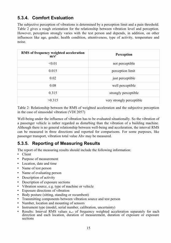
5.3.4. Comfort EvaluationThe subjective perception of vibrations is determined by a perception limit and a pain threshold. Table 2 gives a rough orientation for the relationship between vibration level and perception. However, perception strongly varies with the test person and depends, in addition, on other influences like age, gender, health condition, attentiveness, type of activity, temperature and noise.
RMS of frequency weighted acceleration m/s² Perception
<0.01 not perceptible
0.015 perception limit
0.02 just perceptible
0.08 well perceptible
0.315 strongly perceptible
>0.315 very strongly perceptible
Table 2: Relationship between the RMS of weighted acceleration and the subjective perception in the case of sinusoidal vibration (VDI 2057)
Well-being under the influence of vibration has to be evaluated situationally. So the vibration of a passenger vehicle is rather regarded as disturbing than the vibration of a building machine. Although there is no general relationship between well-being and acceleration, the interval RMS can be measured in three directions and reported for comparisons. For some purposes, like passenger transport, vibration total value Ahv may be measured.
5.3.5. Reporting of Measuring ResultsThe report of the measuring results should include the following information:• Client• Purpose of measurement• Location, date and time • Name of test person • Name of evaluating person • Description of activity• Description of exposure sections• Vibration source, e.g. type of machine or vehicle • Exposure directions of vibration • Body posture (sitting, standing or recumbent)• Transmitting components between vibration source and test person • Number, location and mounting of sensors • Instrument type (model, serial number, calibration, uncertainty)• Results: Interval RMS values awT of frequency weighted acceleration separately for each
direction and each location, duration of measurement, duration of exposure or exposure sections
15
• Exposure sections with high RMS values or high shock components represent an elevated health risk and shall be reported separately with magnitude and duration.
6. Switching the Instrument On and OffTo switch on the VM30-H, push the ON/OFF key and hold it for 2 seconds. The instrument displays its software version and starts to display measuring values based on the last settings.To switch it off, press again the ON/OFF key. Switching off by accidental key press can be avoided with the key lock function. Press the LOCK key and confirm by OK to lock all keys. The keys can be unlocked by pressing the LOCK key and OK again.Please note that the VM30-H can only be switched off in the measuring mode. You must escape from the data logger mode and the menus by using the ESC key before the unit can be switched off.If the shut-off timer was activated (MENU → “8/8: Device settings” → “2/5: Shut-off timer”), the instrument switches off after 1, 10 or 30 minutes.
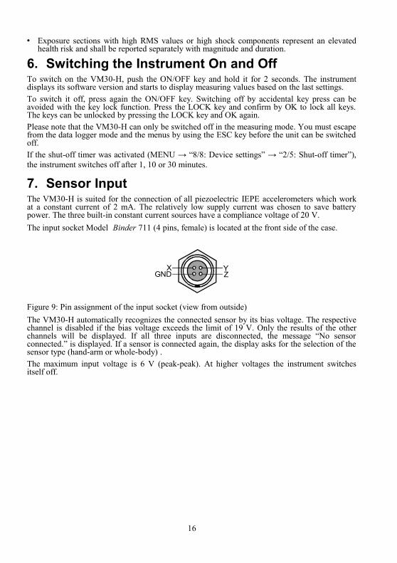
7. Sensor InputThe VM30-H is suited for the connection of all piezoelectric IEPE accelerometers which work at a constant current of 2 mA. The relatively low supply current was chosen to save battery power. The three built-in constant current sources have a compliance voltage of 20 V. The input socket Model Binder 711 (4 pins, female) is located at the front side of the case.
Figure 9: Pin assignment of the input socket (view from outside)The VM30-H automatically recognizes the connected sensor by its bias voltage. The respective channel is disabled if the bias voltage exceeds the limit of 19 V. Only the results of the other channels will be displayed. If all three inputs are disconnected, the message “No sensor connected.” is displayed. If a sensor is connected again, the display asks for the selection of the sensor type (hand-arm or whole-body) .The maximum input voltage is 6 V (peak-peak). At higher voltages the instrument switches itself off.
16
GNDX Y
Z

8. DisplayThe VM30-H has a graphical LCD with a resolution of 32 x 120 dots. It displays clearly the measuring values of three channels simultaneously including units and additional information.Pressing the LIGHT key switches on the backlight. By repeated key press the light is switched off again. Otherwise the light switches off automatically after 30 seconds. Please note, in order to save battery power, use the backlight only when necessary. It increases the total current consumption by 30 %.A typical display in the measuring mode is shown in Figure 10.
Figure 10: Display in the measuring modeDepending on the connected sensor, one, two or three measuring values are displayed side by side. Below you will find the respective channel identifier (X / Y / Z) and the measuring units alternating with the display modes.The messages GAIN UP and GAIN DOWN instead of the measuring value indicate a change in the measuring range by the autoranging function. The VM30-H may also display OVER LOAD instead of the measuring value.The selected filter type is displayed in the center above the measuring results. If one of the averaged display modes eVDV or A(T) has been selected, a message Overload can appear instead of the filter type if an overload condition occurred during the entire duration of measurement.In the upper left corner you can see the number of stored values in the memory. In the data logger mode this number is incremented each time the instrument saves a measuring value. The number alternates with the duration of measurement if one of the averaged display modes eVDV or A(T) is measured.The battery indicator is in the upper right corner. If the battery is fully discharged, the message Bat! is indicated accompanied by a beep sound.
17
Record number in memory and duration of measurementfor eVDV and A(T)
Filter type andoverload during the measuring time foreVDV, Ahv and A(T)
Battery indicator"Ext." for external supply
Measuring valuesX / Y / Z
Units alternatingwith display modes

9. Signal Setup9.1. Vibration QuantityPress the ▲ (RANGE) key to display the vibration quantity menu. The following vibration quantities can be selected using the ▲▼ keys:• Human vibration with the corresponding weighting filters to ISO 8041• Vibration acceleration• Vibration velocity, integrated acceleration signal• Vibration displacement, double integrated acceleration signal
9.2. FiltersThe filter menu appears after a vibration quantity has been selected. The VM30-H provides a set of band-pass or weighting filters for each vibration quantity mode. The weighting filters for human vibration conform to ISO 8041 and cover most applications in this field.
9.2.1. Weighting FiltersThe weighting filters Wb, Wc, Wd, We, Wg, Wh, Wj, Wk and Wm to are only available if the selected vibration quantity is human vibration. They are implemented as IIR digital filters which guarantees high accuracy and stability.
9.2.1.1. Weighting Filter Wb
The weighting filter Wb, which is similar to the filter Wk, is intended for measuring whole-body vibration in fixed-guideway transport systems in seated, standing or recumbent position to the standard ISO 2631-4.
Figure 11: Weighting filter Wb
18
0,01
0,10
1,00
10,00
1 10 100 1000Hz

9.2.1.2. Weighting Filter Wc
The weighting filter Wc is intended for the measurement of whole-body vibration at the seat back in the direction perpendicular to the spinal column to ISO 2631-1.
Figure 12: Weighting filter Wc
9.2.1.3. Weighting Filter Wd
The weighting filter Wd is used for measuring whole-body vibration in seated, standing or recumbent positions at right angles to the spinal column to the standard ISO 2631-1.
Figure 13: Weighting filter Wd
19
0,01
0,10
1,00
10,00
1 10 100 1000Hz
0,01
0,10
1,00
10,00
1 10 100 1000Hz
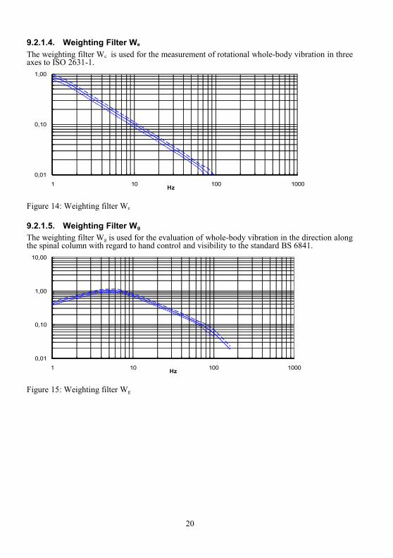
9.2.1.4. Weighting Filter We
The weighting filter We is used for the measurement of rotational whole-body vibration in three axes to ISO 2631-1.
Figure 14: Weighting filter We
9.2.1.5. Weighting Filter Wg
The weighting filter Wg is used for the evaluation of whole-body vibration in the direction along the spinal column with regard to hand control and visibility to the standard BS 6841.
Figure 15: Weighting filter Wg
20
0,01
0,10
1,00
1 10 100 1000Hz
0,01
0,10
1,00
10,00
1 10 100 1000Hz

9.2.1.6. Weighting Filter Wh
The weighting filter Wh is intended for measuring hand-arm vibration in three axes to ISO 5349-1.
Figure 16: Weighting filter Wh
9.2.1.7. Weighting Filter Wj
The weighting filter Wj is used for measuring vibrations acting on the head of a recumbent person in vertical direction (perpendicular to the lying surface) to ISO 2631-1.
Figure 17: Weighting filter Wj
21
0,01
0,10
1,00
10,00
1 10 100 1000 10000Hz
0,01
0,10
1,00
10,00
1 10 100 1000Hz

9.2.1.8. Weighting Filter Wk
The weighting filter Wk is used for measuring whole-body vibrations in the direction of the spinal column in seated and standing position, for measurements in vertical direction (perpendicular to the lying surface) in recumbent position and for vibrations in all three directions acting on the feet in seated position to ISO 2631-1.
Figure 18: Weighting filter Wk
9.2.1.9. Weighting Filter Wm
The weighting filter Wm is intended for measuring whole-body vibrations in buildings in all three directions to ISO 2631-2.
Figure 19: Weighting filter Wm
22
0,01
0,10
1,00
10,00
1 10 100 1000Hz
0,01
0,10
1,00
10,00
1 10 100 1000Hz

9.2.1.10. Combined Weighting FiltersThe weighting filters described in the preceding sections can be applied for measurements in all three directions (X / Y / Z). Additionally, the following useful combinations are available:Wd + Wk: This combination of the filter Wd for the X and Y axes with Wk for the Z axis is used for measurement of whole-body vibrations in seated position at the seat surface. Wd + Wc: This combination of the filter Wd for the X and Y axes with Wc for the Z axis is used for measurement of whole-body vibrations in seated position at the backrest.
Important notice: The measuring axes (X/Y/Z) of the VM30-H refer to the marking on the seat pad accelerometer. For measurements at the backrest or under the back of a recumbent person, the axis definition differs from ISO 2631. According to the standard the Z axis shall always point into the direction of the spinal column. However, the Z axis measured by the VM30-H will point vertically to the back in the mentioned cases. To compensate this, the displayed X and Z values must be swapped.
9.2.2. Band-Pass FiltersBand-pass filters differ from weighting filters by their linear passband response. They are used for various applications, such as machine monitoring and building vibrations.The VM30-H contains the following band-pass filters:• 0.4 - 100 Hz for the measurement of building vibrations to DIN 4150• 2 - 300 Hz for measurements at slow running machinery to ISO 10816-6• 0.4 -1250 Hz• 10 -1250 Hz for machine vibrations (vibration severity) to ISO 10816-1• 0.4 Hz - 10 kHz maximum bandwidth of the VM30-H• 1 kHz - 10 kHz for bearing vibrationsThese band-pass filters are only available if acceleration has been selected as vibration quantity. For vibration velocity only the filters 2 - 300 Hz and 10 - 1250 Hz can be selected due to the limited frequency response after integration. Vibration displacement can only be measured between 6 and 200 Hz.The following diagram shows the frequency response curves of all band-pass filters.
Figure 20: Frequency response curves of the band-pass filters
23
0,001
0,01
0,1
1
10
0,1 1 10 100 1000 10000 100000Hz
0,4-100Hz
0,4-1250Hz
2-300Hz
10-1250Hz
0,4-10000Hz
1000-10000Hz
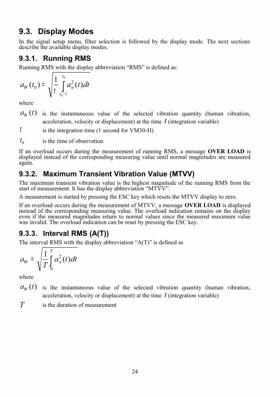
9.3. Display ModesIn the signal setup menu, filter selection is followed by the display mode. The next sections describe the available display modes.
9.3.1. Running RMSRunning RMS with the display abbreviation “RMS” is defined as:
∫−
=0
0
)(1)( 20
t
twW dttata
ττwhere
)(taW is the instantaneous value of the selected vibration quantity (human vibration, acceleration, velocity or displacement) at the time t (integration variable)
τ is the integration time (1 second for VM30-H)
0t is the time of observation
If an overload occurs during the measurement of running RMS, a message OVER LOAD is displayed instead of the corresponding measuring value until normal magnitudes are measured again.
9.3.2. Maximum Transient Vibration Value (MTVV)The maximum transient vibration value is the highest magnitude of the running RMS from the start of measurement. It has the display abbreviation “MTVV”.A measurement is started by pressing the ESC key which resets the MTVV display to zero. If an overload occurs during the measurement of MTVV, a message OVER LOAD is displayed instead of the corresponding measuring value. The overload indication remains on the display even if the measured magnitudes return to normal values since the measured maximum value was invalid. The overload indication can be reset by pressing the ESC key.
9.3.3. Interval RMS (A(T))The interval RMS with the display abbreviation “A(T)” is defined as
∫=T
wW dttaT
a0
2 )(1
where
)(taW is the instantaneous value of the selected vibration quantity (human vibration, acceleration, velocity or displacement) at the time t (integration variable)
T is the duration of measurement
24
Please note that the autoranging function is deactivated when measuring interval RMS. Select a fixed measuring range before starting the measurement (see section 10). If autoranging has been activated, a message is displayed after the selection of interval RMS, showing that autoranging is not available in this mode and the respective channel is set to gain = 0.1, corresponding to the highest range. Another measuring range can be selected manually, if desired (see section 10).Measurement is started with the ESC key. The displayed A(T) value is then reset and the integration timer restarted. The elapsed integration time is displayed in hours, minutes and seconds in the upper left corner of the display, alternating with the record number.Maximum integration time is 10 hours.If an overload occurs during the measurement of interval RMS, a message OVER LOAD is displayed instead of the corresponding measuring value until normal magnitudes are measured again. Additionally, a message Overload is displayed in the center above the measuring values, alternating with the filter type (Figure 10). This indicates that an overload has occurred in at least one channel during the entire integration time. It can be reset by starting a new measurement using the ESC key.In contrast to the running RMS, the interval RMS does almost not react to short vibration events. Interval RMS is of particular interest for the measurement of human vibration.
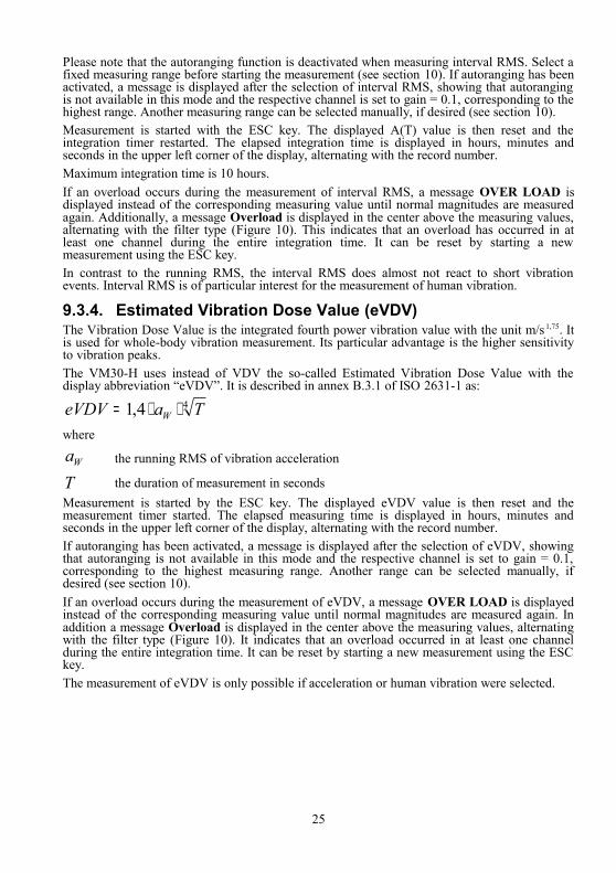
9.3.4. Estimated Vibration Dose Value (eVDV)The Vibration Dose Value is the integrated fourth power vibration value with the unit m/s 1,75. It is used for whole-body vibration measurement. Its particular advantage is the higher sensitivity to vibration peaks. The VM30-H uses instead of VDV the so-called Estimated Vibration Dose Value with the display abbreviation “eVDV”. It is described in annex B.3.1 of ISO 2631-1 as:
44,1 TaeVDV W ⋅⋅=where
Wa the running RMS of vibration acceleration
T the duration of measurement in secondsMeasurement is started by the ESC key. The displayed eVDV value is then reset and the measurement timer started. The elapsed measuring time is displayed in hours, minutes and seconds in the upper left corner of the display, alternating with the record number.If autoranging has been activated, a message is displayed after the selection of eVDV, showing that autoranging is not available in this mode and the respective channel is set to gain = 0.1, corresponding to the highest measuring range. Another range can be selected manually, if desired (see section 10).If an overload occurs during the measurement of eVDV, a message OVER LOAD is displayed instead of the corresponding measuring value until normal magnitudes are measured again. In addition a message Overload is displayed in the center above the measuring values, alternating with the filter type (Figure 10). It indicates that an overload occurred in at least one channel during the entire integration time. It can be reset by starting a new measurement using the ESC key.The measurement of eVDV is only possible if acceleration or human vibration were selected.
25

9.3.5. Vibration Total Value (Ahv)Vibration Total Value with the display abbreviation “Ahv” is determined from vibration in three orthogonal directions, is calculated as follows
222222hwzzhwyyhwxxhv akakakA ++=
whereahwx, ahwy, ahwz are the interval RMS values of X / Y / Z axeskx, ky, kz are multiplying factorsAfter the selection of the Vibration Total Value you will be asked for the multiplying factors kx, ky and kz. These factors can be used for individual weighting of the three axes. Values between 0 and 2.0 can be entered. This may be useful when the triaxial Vibration Total Value is measured in one or two directions only. Deactivated channels are considered as zero. The dominating axis with the highest magnitude can then be multiplied by a correction factor between 1.0 and 1.7 (see ISO 5349-1).The factors kx, ky and kz are also used for the measurement of whole-body vibration to ISO 2631-1.When measuring the Vibration Total Value, the VM30-H automatically sets the measuring ranges of all three channels to the highest one of the three selected ranges.If autoranging has been activated, a message is displayed after the selection of Ahv, showing that autoranging is not available in this mode and the gain of all channels is set to 0.1, corresponding to the highest measuring range. Another range can be selected manually, if desired (see section 10).If an overload occurs during the measurement of Vibration Total Value, a message OVER LOAD is displayed instead of the measuring value until normal magnitudes are measured again. Additionally a message Overload is displayed in the center above the measuring value, alternating with the filter type (Figure 10). It indicates that an overload occurred in at least one channel during the entire integration time. It can be reset by starting a new measurement using the ESC key.The Vibration Total Value is mainly used for human vibration measurement. However, with the VM30-H it can also be applied for measuring velocity and displacement.
9.3.6. Peak Value (PEAK)Peak value with the display abbreviation “PEAK” is the highest absolute magnitude (negative or positive) of the instantaneous vibration signal (human vibration, acceleration, velocity or displacement) over a measuring period of one second. If an overload occurs during the measurement of the peak value, a message OVER LOAD is displayed instead of the corresponding measuring value until normal magnitudes are measured again.
26
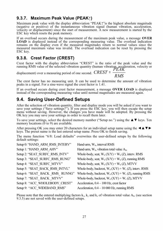
9.3.7. Maximum Peak Value (PEAK↑)Maximum peak value with the display abbreviation “PEAK↑”is the highest absolute magnitude (negative or positive) of the instantaneous vibration signal (human vibration, acceleration, velocity or displacement) since the start of measurement. A new measurement is started by the ESC key which resets the peak memory.If an overload occurs during the measurement of the maximum peak value, a message OVER LOAD is displayed instead of the corresponding measuring value. The overload indication remains on the display even if the measured magnitudes return to normal values since the measured maximum value was invalid. The overload indication can be reset by pressing the ESC key.
9.3.8. Crest Factor (CREST)Crest factor with the display abbreviation “CREST” is the ratio of the peak value and the running RMS value of the selected vibration quantity (human vibration, acceleration, velocity or
displacement) over a measuring period of one second. RMS
PEAKCREST =
The crest factor has no measuring unit. It can be used to determine the amount of vibration peaks in a signal. For a sine-wave signal the crest factor is 1.41.If an overload occurs during crest factor measurement, a message OVER LOAD is displayed instead of the corresponding measuring value until normal magnitudes are measured again.
9.4. Saving User-Defined SetupsAfter the selection of vibration quantity, filter and display mode you will be asked if you want to save your settings (“Save settings?”). If you press the ESC key, you will then escape the setup menu without saving. However, the changes you have made will be adopted. By pressing the OK key you may save your settings in order to recall them later. To save your settings, select the desired memory number (“Setup no.”) using the ▲▼ keys. Ten memory locations (0 to 9) are available. After pressing OK you may enter 20 characters for an individual setup name using the ◄▲▼► keys. The preset name is the last entered setup name. Press OK to finish saving.The menu function “6/8: Load defaults” overwrites the user-defined setups by the following default settings:Setup 0: “HAND_ARM_RMS_INTERV” Hand-arm, Wh, interval RMS Setup 1: “HAND_ARM_AHV” Hand-arm, Wh, vibration total value Ahv
Setup 2: “SEAT_SURFC_RMS_INTV” Whole-body, seat, Wd (X/Y) + Wk (Z), interv. RMSSetup 3: “SEAT_SURFC_RMS_RUNG” Whole-body, seat, Wd (X/Y) + Wk (Z), running RMSSetup 4: “SEAT_SURFC_MTVV” Whole-body, seat, Wd (X/Y) + Wk (Z), MTVVSetup 5: “SEAT_BACK_RMS_INTVL” Whole-body, backrest, Wd (X/Y) + Wc (Z), interv. RMSSetup 6: “SEAT_ BACK _RMS_ RUNNG” Whole-body, backrest, Wd (X/Y) + Wc (Z), running RMSSetup 7: “SEAT_ BACK _MTVV” Whole-body, backrest, Wd (X/Y) + Wc (Z), MTVVSetup 8: “ACC_WHOLEBODY_CREST” Acceleration, 0.4 – 100 Hz, crest factorSetup 9: “ACC_WIDEBAND_RMS” Acceleration, 0.4 – 10 000 Hz, running RMS
Please note that the entered multiplying factors kx, ky and kz of vibration total value Ahv (see section 9.3.5) are not saved with the user-defined setups.
27

9.5. Loading User-Defined SetupsTo change quickly between different vibration quantities, filters and display modes you may load your own user-defined setups. Press the LOAD key and select the desired setup using the ▲▼ keys. After pressing OK the VM30-H will measure with the new settings.
10. Measuring Range and AutorangingThe VM30-H has four measuring ranges which can be selected in menu “1/8: Gain”. Choose one after the other the measuring ranges for X, Y and Z. The ranges displayed in the menu depend on the selected vibration quantity. Important: The measuring ranges refer to the peak amplitude before filtering and integration. The actually displayed values may be higher when very low frequencies are measured in the integrating modes (velocity or displacement). On the other hand, the actually displayed values may not reach the range limits when signal frequencies in the attenuating band of the filters or integrators are measured.The following table shows the available measuring ranges depending on the vibration quantity and the transducer sensitivity:
Internal Gain
Vibration acceleration or human vibration
1 mV/ms-2 10 mV/ms-2
Vibration velocity
1 mV/ms-2 10 mV/ms-2
Vibration displacement
1 mV/ms-2 10 mV/ms-2
100 12 m/s²peak 1.2 m/s²peak 120 mm/s peak 12 mm/s peak 1.2 mmpeak 0.120 mmpeak
10 120 m/s²peak 12 m/s²peak 1.2 m/s peak 0.12 m/s peak 12 mmpeak 1.2 mmpeak
1 1200 m/s²peak 120 m/s²peak 12 m/s peak 1.2 m/s peak 120 mmpeak 12 mmpeak
0.1 6000 m/s²peak 600 m/s²peak 60 m/s peak 6 m/s peak 600 mmpeak 60 mmpeak
The measuring ranges are selected with the ▲▼ keys and confirmed with OK.For the display modes RMS, MTVV, PEAK, PEAK↑ and CREST an Autoranging function is available. The autoranging function switches to a higher measuring range at 95 % of full scale and to a lower range at 8 % of full scale.If you have chosen autoranging, the display will show in the measuring mode GAIN UP if the measuring range is being lowered or GAIN DOWN if the measuring range is being increased. During the settling time of approximately 5 seconds after changing the range the VM30-H will display OVER LOAD.When measuring vibration total value Ahv, the measuring range of all three channels is set automatically to the lowest one of the three selected ranges.Notice for the use of autoranging: If the measured vibration level should be very changeable, it may be advisable to use fixed measuring ranges instead of autoranging to avoid continuously changing ranges. This may also be the case if the vibration level should be near the switch limits of 8 % or 95 % of full scale.
28

11. Overload IndicationThe overload indication of the VM30-H monitors the following points of the signal path:• Overload or saturation at the sensor output at a peak sensor voltage above ±6 V.• Input signals exceeding ±12 mV, ±120 mV or ±1200 mV depending on the selected
measuring range. With the highest measuring range the maximum input magnitude is limited to ±6 V by the a.m. maximum sensor output.
• Overload at the integrator outputs.The instrument has two kinds of overload indicators. An overload of the currently displayed value is indicated as a message OVER LOAD instead of the measuring value for the corresponding channel.A second overload message can appear instead of the filter type on the display above the measuring results. This may happen if one of the averaging display modes eVDV, A(T) or Ahv has been selected. It indicates that an overload condition occurred during at least one measuring cycle on one or more channels during the entire averaging time. If the message Overload appears, the displayed results may be invalid. This overload message is erased when starting a new measurement by pressing the ESC key.
12. Saving Measuring ResultsThe VM30-H can store between 1000 and 3000 measurements, depending on the selected recording mode.The following recording modes are available:• Manual recording of a single measurement in X / Y / Z direction by the SAVE key. You
may specify whether a comment, the clock time and the date are to be added to the saved measuring values.
• Time-controlled recording in the data logger mode in a user-defined time interval between 1 second and some hours.
The selection of the recording mode is made in the menu “2/8: Recording setup”. Select manual recording (manually by SAVE key) or time-controlled recording (by data logger).The two recording modes cannot be mixed in the memory. The VM30-H can either hold manually recorded or logger data. If the instrument should detect data of the other type in its memory, a warning will inform you that the memory will be overwritten.
12.1. Manual Recording by the SAVE KeyAfter the selection of manual recording in the submenu “2/8: Recording setup” you will then be asked if you want to add a comment. The comment with up to 20 characters may contain, for example, information about the measuring point or the test conditions. Recording without comment may save approximately 40 % memory space. In the next step you can decide whether you want to add the clock time and the date to each record. They occupy approximately 10 % of the memory space.The actual recording is done by pressing the SAVE key when the instrument shows measuring values. If the comment function has been enabled, you will be asked to enter a text by means of the ◄▲▼► keys. The comment may consist of up to 20 capital letters and numbers.After pressing OK, the measurement is saved while the display shows date, time and available memory space for two seconds.Should the memory contain data which was saved in the time-controlled (logger) mode, a warning indicates that the memory will be overwritten.
29

Each recorded measurement gets a consecutive number. The next available number is displayed in the upper left corner as “Mxxxx” (see Figure 10). If the memory is full, a message “Data memory full.” appears after pressing the SAVE key.The available memory space can be checked by the ◄ (INFO) key during measurement. Occupied memory is indicated as a black bargraph. To erase the entire data memory, press MENU and go to “4/8: Erase memory”. An empty memory can be recognized by the record number “M0000”.
12.2. Automatic Recording in the Data Logger ModeAfter selecting the data logger mode in the menu “2/8: Recording setup” you are asked to select a time unit. Using the ▲▼ keys you may choose between seconds, minutes or hours. After pressing OK you may enter a time interval between 1 and 9999 using the ◄▲▼► keys. In the next step you enter the log duration. It must be longer than at least one log interval. Otherwise an error message will be displayed. If you confirm the preset value “0000”, the maximum log duration of 10 000 seconds, minutes or hours will be used. In the last step enter a name for the log file using the ◄▲▼► keys. It may consist of up to 20 capital letters and numbers. Now the settings for the data logger functions are complete.The logger is started by the SAVE key. First the log interval, the log duration and the available memory are displayed for your information. Confirm by pressing OK. Should the VM30-H memory still contain manually saved data, a warning will inform you that this data must be overwritten. Data logger operation can be recognized by the increasing record number “M0000” in the upper left display corner. While the data logger is running, the MENU, RANGE and LOAD keys are disabled. When pressing one of these keys or the ESC key, a message “Logger halted.“ appears. You may resume logging by OK or finish by ESC.The VM30-H can hold several independent log files in its memory. A new log file can be appended by pressing the SAVE key again. Before saving a new log file, you can also change the settings in the menu “2/8: Recording setup” if desired.It is useful to lock the keys of the VM30-H when it is in the log mode to avoid interruption by accidental key pressure. Press the LOCK key and confirm by OK. Now all keys are disabled. To unlock, press the LOCK key again and confirm by OK.To delete the entire memory, select the menu function “4/8: Erase memory“. An empty memory can be recognized by the record “M0000”.
30

13. Data Transmission to the PCMicrosoft Excel is a widely used software for calculation and visualization of data in table form. It also enables data to be converted into other formats. Therefore the data transmission from the VM30-H to the PC is based on Excel.
13.1. Preparing the Import of Data into ExcelThe instrument uses a serial (RS-232) interface for PC connection (see section 17). A commercially available RS-232 / USB adapter can also be used.For processing, displaying and saving data, a Microsoft Excel file is provided. It is compatible with Windows 2000, XP, Vista and Windows 7 . The Excel file includes a Visual Basic Macro which enables Excel to read data from the serial interface and to sort it into table fields. To give the macro access to the serial interface, the file VM30.DLL must be copied into the system folder:…/WINNT under Windows 2000 or …/WINDOWS under Windows XP Please copy the Excel table file VM30.XLS into your working directory.
Notice: The latest versions of the files VM30.XLS and VM30.DLL can be downloaded free of charge from our web site at http://www.mmf.de/software_download.htm.
13.2. Importing VM30-H Data with the Excel Macro Before you open the file VM30.XLS please make sure that the use of macros is enabled. Open the menu Tools / Macro / Security. If you select the security level „Medium“ you will be prompted to enable macros each time you open the file VM30.XLS. The security level “Low” presents no prompt and macros are allowed. However, be aware of the potential risk of macro viruses when using low security.Open the file VM30.XLS and save it under a new name to avoid overwriting.
Figure 21: Excel file import dialog in VM30.XLSConnect the VM30-H to the RS-232 interface of your PC via the supplied interface cable VM30-I. Alternatively, the supplied USB / RS-232 adapter can be used. After its first connection a device driver will be installed. This should be done automatically by Windows if your PC has internet access. You may also download the driver for your system version from http://www.ftdichip.com/Drivers/VCP.htm and install it manually. Windows will assign a COM port number to the USB adapter. This number can be found in Windows under Control Panel / Device Manager / Ports.Select the used interface in the drop-down menu “COM-Port“ of the Excel file.
31
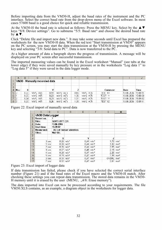
Before importing data from the VM30-H, adjust the baud rates of the instrument and the PC interface. Select the correct baud rate from the drop-down menu of the Excel software. In most cases 57600 baud is a good choice for quick and reliable transmission.At the VM30-H the baud rate is selected as follows: Press the MENU key. Select by the ▲▼ keys “8/8: Device settings”. Go to submenu “5/5: Baud rate“ and choose the desired baud rate by ▲▼.Click “Delete file and import new data.”. It may take some seconds until Excel has prepared the worksheets for the new VM30-H data. When the red text “Start transmission at VM30” appears on the PC screen, you may start the data transmission at the VM30-H by pressing the MENU key and selecting “3/8: Send data to PC”. Data is now transferred to the PC. At a higher amount of data a bargraph shows the progress of transmission. A message will be displayed on your PC screen after successful transmission.The imported measuring values can be found in the Excel worksheet “Manual” (see tabs at the lower edge) if they were saved manually by key pressure or in the worksheets “Log data 1” to “Log data 5” if they were saved in the data logger mode.
Figure 22: Excel import of manually saved data
Figure 23: Excel import of logger dataIf data transmission has failed, please check if you have selected the correct serial interface number (Figure 21) and if the baud rates of the Excel macro and the VM30-H match. After checking these settings you can repeat data transmission. The stored data remains in the VM30-H memory until it is erased by the user (MENU, „4/8: Erase memory“).The data imported into Excel can now be processed according to your requirements. The file VM30.XLS contains, as an example, a diagram object in the worksheets for logger data.
32

Figure 24: Example for displaying measured data in ExcelNotice: Data recorded in the logger mode may have different units depending on the magnitude, like mm/s or m/s. The Excel macro transforms all measuring values into m/s², mm/s or µm.
13.3. Calculation of the Daily Exposure Value A(8)The daily exposure value A(8) helps to compare the vibration exposure for different persons and activities. A(8) is also the basis for the determination of the "daily exposure limit" and the "daily exposure action value" according to the EU directive 2002/44/EC. More information concerning this directive can be found at:http://www.mmf.de/PDF/AN21e-Human Vibration, EC Directive.pdfThe daily exposure value A(8) is calculated as follows:
A8=Ahv TT 0
whereAhv is the vibration total value (see page 26)T is the total duration of the exposure to Ahv during a work dayT0 is the reference duration of 8 hoursIf the work is separated into several activities with different vibration exposures, the daily exposure value can be calculated as follows:
A8= 1T 0
∑i=1
n
Ahvi ² T i
wheren is the number of activitiesAhvi is the vibration total value of the ith activityTi is the duration of the ith activityThe Excel macro of the VM30-H allows the calculation of A(8) for several activities and persons.Precondition for A(8) calculation is saving several vibration total values (Ahv) by means of the manual recording mode (compare page 29). For each activity of each person a measuring value including an informative comment is saved.
33

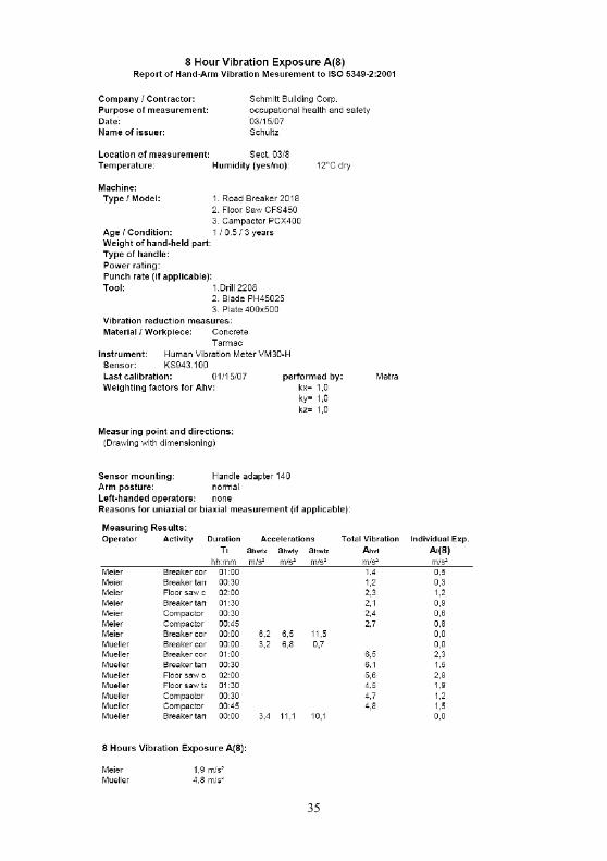
When the Ahv values are imported into the Excel macro, they will appear in addition to the worksheet "Manual" also in the worksheet "A(8) Calculation". A running number, the entered comment, date and time are added to the Ahv values in this worksheet.Now each Ahv value must be assigned to a person and an activity. First of all the entries for Person 1, Person 2 etc. in the upper part of the worksheet "A(8) Calculation" should be overwritten with real names. The same is done with the activities.Now assign line by line the measuring values in the left part (1.) of the table to the persons and activities in the middle part (2.) using pull-down menus. In addition for each Ahv value the exposure duration must be entered in the format hh:mm. An example is shown in Figure 25.When the assignment is finished, click on the button "Calculate A(8)". In the right part of the table (3.) will appear the calculated daily exposure values for each person.In the worksheet "A(8) Report" the results are recorded. In addition to the vibration total values and the calculated vibration exposure values also interval RMS values ahwix, ahwiy and ahwiz are listed if such values have been saved. For each activity a partial exposure vale Ai(8) is calculated which helps to evaluate the influence of individual activities. You may add information regarding the measuring conditions, the test persons and the tested equipment. The prepared protocol conforms with the requirements of ISO 5349. An example protocol can be found at the end of this chapter.Please do not forget to save the Excel macro under a new file name.
On the next page you see an example report for A(8) measuring results generated with the Excel macro.
34
Figure 25: Example of A(8) calculation in Excel
35

13.4. Function of the Excel Macro Excel macros are programmed in Visual Basic. Via the Excel menu Tools / Macro / Visual Basic Editor you may view and modify the source code of the VM30-H macro.The only specific part for the VM30-H is the function declaration for RS-232 communication which is embedded by means of the file VM30-DLL:
Declare Sub OPENCOM Lib "VM30.DLL" (ByVal COM_Parameter$)Declare Sub CLOSECOM Lib "VM30.DLL" ()Declare Sub TIMEOUT Lib "VM30.DLL" (ByVal ms%)Declare Sub STRLENGTH Lib "VM30.DLL" (ByVal B%)Declare Function STRREAD Lib "VM30.DLL" (ByVal D$) As Integer
These commands have the following meaning:OPENCOM (Parameter$) opens a serial interface using the parameter string in the form „COM1:57600,E,7,1“ (COM port number, baud rate, parity, data bits, stop bits).CLOSECOM closes the serial interface.TIMEOUT (ms) is the maximum waiting time when receiving data from the serial interface in milliseconds. Transmission is stopped if no data is received before the waiting time is over.STRLENGTH (Length) is the length of a character string to be received.STRREAD (String) receives a character string with the length defined by STRLENGTH. When the time defined in TIMEOUT is exceeded, the function returns the string “Fehler”. The string variable must be filled with space characters before reception.
Example: SRLENGTH 8 Data$ = " " STRREAD (Data$) The program code of the VM30-H macro consists mainly of the reception of character strings from the instrument and their interpretation and display in table fields.Feel free to modify the macro or the Excel file according to your requirements.
36
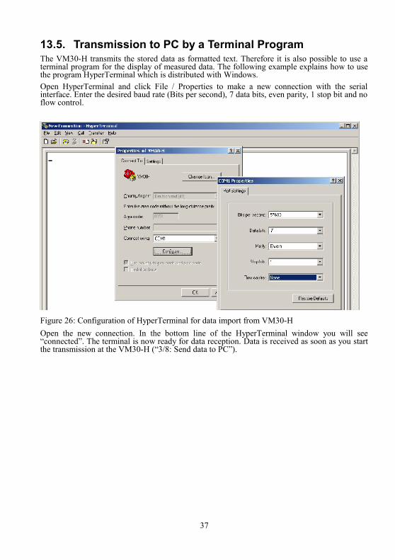
13.5. Transmission to PC by a Terminal ProgramThe VM30-H transmits the stored data as formatted text. Therefore it is also possible to use a terminal program for the display of measured data. The following example explains how to use the program HyperTerminal which is distributed with Windows.Open HyperTerminal and click File / Properties to make a new connection with the serial interface. Enter the desired baud rate (Bits per second), 7 data bits, even parity, 1 stop bit and no flow control.
Figure 26: Configuration of HyperTerminal for data import from VM30-H Open the new connection. In the bottom line of the HyperTerminal window you will see “connected”. The terminal is now ready for data reception. Data is received as soon as you start the transmission at the VM30-H (“3/8: Send data to PC”).
37
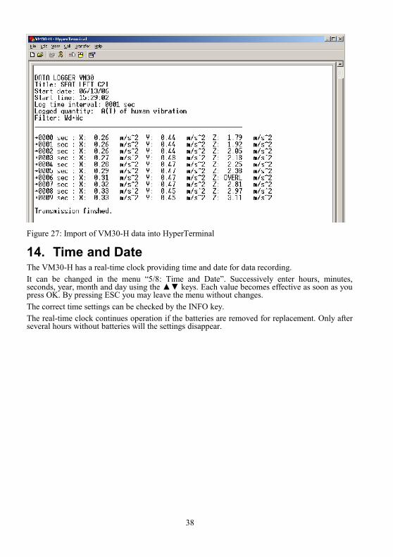
Figure 27: Import of VM30-H data into HyperTerminal
14. Time and DateThe VM30-H has a real-time clock providing time and date for data recording. It can be changed in the menu “5/8: Time and Date”. Successively enter hours, minutes, seconds, year, month and day using the ▲▼ keys. Each value becomes effective as soon as you press OK. By pressing ESC you may leave the menu without changes. The correct time settings can be checked by the INFO key.The real-time clock continues operation if the batteries are removed for replacement. Only after several hours without batteries will the settings disappear.
38
15. Calibration and Function CheckThe VM30-H is supplied in calibrated condition. That means the displayed vibration is within the tolerance range provided that the sensitivity of the used transducer was entered correctly. When the instrument was purchased with one or two sensors, the sensitivities are stored in the VM30-H memory. The entered transducer sensitivities can be found in the supplied calibration certificate.The calibration interval depends on the intensity of use. Metra recommends to recalibrate the equipment every 1 to 2 years. You may send the instrument for recalibration to the manufacturer or to an independent lab.In addition to calibration the standards for human vibration measurement demand a regular function check.After changing the accelerometer, its sensitivities must be entered. When you connect the sensor cable, the calibration menu will open automatically. There you can select between two sensor types. These will be usually a hand-arm and whole-body accelerometer. After selecting the sensor you may either skip the calibration if the sensitivities have already been entered or you may calibrate the sensor in two different ways:• Sensitivity input as numbers in mV/ms-2 for each axis • Calibration of each axis by a reference shaker which supplies a constant sinusoidal vibration
signal of known magnitude.
15.1. Entering Transducer Sensitivities The menu for entering sensitivities opens either when you connect a transducer or when you press the MENU key and select “7/8: Sensor”. After selecting the transducer to be calibrated, answer the question “Edit this sensor?“ with “Yes”. Now you can select the nominal sensitivity of the transducer. Nominal sensitivities of 1 and 10 mV/m/s-² are available. Press OK and choose the calibration mode “By transducer sensitivity”. Press OK again and enter the sensitivities in mV/ms-2 from the supplied calibration certificate successively for X, Y and Z using the ◄▲▼► keys. The permissible range is 0.800 to 1.200 mV/ms -2 and 8.00 to 12.00 mV/ms-2 respectively. An error message is displayed if higher or lower values are entered.Enter a sensor name with up to 20 characters using the ◄▲▼► keys and confirm with OK.The VM30-H may store the sensitivities of two transducers. You may check the entered values anytime when you open the menu “7/8: Sensor”, choose “Edit this sensor?“, confirm the nominal sensitivity by OK and choose “By transducer sensitivity”. If you do not want to change the calibration values, only press the OK key.
15.2. Sensitivity Calibration by a Vibration Calibrator The menu for mechanical calibration of transducer sensitivities may be reached either by connecting a transducer or pressing the MENU key and selecting “7/8: Sensor”. After selecting the transducer to be calibrated, answer the question “Edit this sensor?“ with “Yes”. Now you can select the nominal sensitivity of the transducer. Nominal sensitivities of 1 and 10 mV/m/s -² are available. Press OK and choose the calibration mode “By vibration calibrator”. The calibration feature of the VM30-H is based on a reference vibration signal of 10 m/s² (RMS) with a frequency of 159.2 Hz. Several calibrators of this type are available, for example VC10 series of Metra.Calibration starts with the X axis. Mount the sensor facing towards direction X onto the shaker head of your calibrator and switch the calibrator on. Contact Metra for suitable mounting accessories. The VM30-H will now display the measured vibration level in m/s². Adjust the display exactly to 10.0 m/s² by means of the ▲▼ keys.Subsequently calibrate the other two channels in the same way.
39

You may finish calibration without changing the active channel by pressing ESC. The calibration of other channels which have been changed before remains stored.Enter a sensor name with up to 20 characters using the ◄▲▼► keys and confirm with OK.The VM30-H may store the sensitivities of two transducers. You may check the entered values anytime when you open the menu “7/8: Sensor”, choose “Edit this sensor?“, confirm the nominal sensitivity by OK and choose “By transducer sensitivity”. If you do not want to change the calibration values, only press the OK key.
15.3. Mechanical CalibrationMechanical calibration may be used to check the accuracy of the complete measuring chain of accelerometer and VM30-H. The following calibration procedure requires that the sensitivities of the used transducer have been entered correctly as shown above.For mechanical calibration the transducer is mounted successively in the three directions onto an electrodynamic shaker. For mounting accessories, please contact Metra.Calibration is performed at a reference signal of 5 m/s² (RMS) / 80 Hz for hand-arm sensors and at 0.5 m/s² / 16 Hz for whole-body sensors. At the VM30-H the filter 0.4 Hz – 100 Hz or 10 – 1250 Hz is selected. The following table shows the vibration levels and VM30-H settings for mechanical calibration:
Channel Shaker Signal Level (RMS) Frequency Settings at VM30-H Typical display values (m/s²)
X Y ZMax. Error
Calibration with hand-arm accelerometer (nominal sensitivity 1 mV/ms-2):X 50 m/s² 80 Hz 10-1250 Hz, a, A(T), 120 m/s² 50.0 0 0 4 %Y 50 m/s² 80 Hz 10-1250 Hz, a, A(T), 120 m/s² 0 50.0 0 4 %Z 50 m/s² 80 Hz 10-1250 Hz, a, A(T), 120 m/s² 0 0 50.0 4 %
Calibration with whole-body accelerometer (nominal sensitivity 10 mV/ms-2):X 5 m/s² 16 Hz 0.4-100 Hz, a, A(T), 12 m/s² 5.00 0 0 4 %Y 5 m/s² 16 Hz 0.4-100 Hz, a, A(T), 12 m/s² 0 5.00 0 4 %Z 5 m/s² 16 Hz 0.4-100 Hz, a, A(T), 12 m/s² 0 0 5.00 4 %
15.4. Electrical CalibrationThe VM30-H can be calibrated without the sensor by means of an electrical generator signal. Since the inputs are equipped with constant current sources, RC coupling circuits must be connected between the VM30-H and the generator. Figure 28 shows the the required components and the pin assignment of the input socket.
The 10 kΩ resistor is necessary to sink the constant current. The voltage drop is approximately 10 V. This DC voltage is decoupled from the generator output by a 100 µF electrolytic capacitor. The capacitor should be rated for at least 35 V. Please make sure that the generator output is not affected by a load of approximately 3 kΩ.The following table shows the steps which are performed by factory calibration and the corresponding generator signals. The shown values are based on an entered transducer sensitivity of 10 mV/ms-2. Chann. Generator signal Settings at VM30-H Typical display values (m/s²) Max. error
40
Figure 28: Connecting the VM30-H inputs to a generator
GNDX Y
Z
+
4k7
1000µ
GeneratorGND
X/Y/Z

Level (RMS) Frequency X Y Z Filters at reference frequency:XYZ 5 mV 79.58 Hz Wh, HV, A(T), G=1000 0.101 0.101 0.101 3 %XYZ 5 mV 15.92 Hz Wb, HV, A(T), G=1000 0.4063 0.4063 0.4063 3 %
Z 5 mV 15.92 Hz Wc, HV, A(T), G=1000 0.2573 3 %XY 5 mV 15.92 Hz Wd, HV, A(T), G=1000 0.06305 0.06305 5 %
XYZ 5 mV 15.92 Hz We, HV, A(T), G=1000 0.032 0.032 0.032 7 %XYZ 5 mV 15.92 Hz Wg, HV, A(T), G=1000 0.243 0.243 0.243 3 %XYZ 5 mV 15.92 Hz Wj HV, A(T), G=1000 0.5095 0.5095 0.5095 3 %XYZ 5 mV 15.92 Hz Wk, HV, A(T), G=1000 0.3859 0.3859 0.3859 3 %XYZ 5 mV 15.92 Hz Wm, HV, A(T), G=1000 0.1681 0.1681 0.1681 3 %XYZ 5 mV 15.92 Hz 0,4-100 Hz, a, A(T), G=1000 0.500 0.500 0.500 3 %XYZ 5 mV 15.92 Hz 0.4-100 Hz, a, RMS, G=1000 0.500 0.500 0.500 3 %
Cross-talk between channels X, Y and Z:X 500 mV 80 Hz 0.4-1250 Hz, a, RMS, G=10 50.0 <0.25 <0.25Y 500 mV 80 Hz 0.4-1250 Hz, a, RMS, G=10 <0.25 50.0 <0.25Z 500 mV 80 Hz 0.4-1250 Hz, a, RMS, G=10 <0.25 <0.25 50
Chann. Generator signalLevel (RMS) Frequency Settings at VM30-H Typical display values (m/s²)
X Y Z Max. error
XYZ 1000 mV 80 Hz 0.4-1250 Hz, a, RMS, G=1 100 100 100 3 %XYZ 316 mV 80 Hz 0.4- 1250 Hz, a, RMS, G=10 31.6 31.6 31.6 3 %XYZ 100 mV 80 Hz 0.4- 1250 Hz, a, RMS, G=10 10.0 10.0 10.0 3 %XYZ 31.6 mV 80 Hz 0.4- 1250 Hz, a, RMS, G=100 3.16 3.16 3.16 3 %XYZ 10 mV 80 Hz 0.4- 1250 Hz, a, RMS, G=100 1.00 1.00 1.00 3 %XYZ 3.16 mV 80 Hz 0.4- 1250 Hz, a, RMS, G=1000 0.316 0.316 0.316 3 %XYZ 1 mV 80 Hz 0.4- 1250 Hz, a, RMS, G=1000 0.100 0.100 0.100 3 %XYZ 2000 mV 80 Hz 0.4- 1250 Hz, a, RMS, G=1 200 200 200 3 %XYZ 632 mV 80 Hz 0.4- 1250 Hz, a, RMS, G=10 63.2 63.2 63.2 3 %XYZ 200 mV 80 Hz 0.4- 1250 Hz, a, RMS, G=10 20.0 20.0 20.0 3 %XYZ 63.2 mV 80 Hz 0.4- 1250 Hz, a, RMS, G=100 6.32 6.32 6.32 3 %XYZ 20 mV 80 Hz 0.4- 1250 Hz, a, RMS, G=100 2.00 2.00 2.00 3 %XYZ 6.32 mV 80 Hz 0.4- 1250 Hz, a, RMS, G=1000 0.632 0.632 0.632 3 %XYZ 2 mV 80 Hz 0.4- 1250 Hz, a, RMS, G=1000 0.200 0.200 0.200 3 %
Filter characteristics at selected frequencies:XYZ 500 mV 1 Hz Wb, HV, RMS, G=10 19,3 19,3 19,3 11 %XYZ 500 mV 1 Hz Wd+Wc, HV, RMS, G=10 50,6 50,6 49,6 21 %XYZ 500 mV 1 Hz Wd+Wk, HV, RMS, G=10 50,6 50,6 24,1 21 %XYZ 500 mV 1 Hz We, HV, RMS, G=10 44,0 44,0 44,0 11 %XYZ 500 mV 1 Hz Wg, HV, RMS, G=10 21,2 21,2 21,2 50 %XYZ 500 mV 1 Hz Wh, HV, RMS, G=10 1,3 1,3 1,3 -100 %XYZ 500 mV 1 Hz Wj, HV, RMS, G=10 24,2 24,2 24,2 11 %XYZ 500 mV 1 Hz Wk, HV, RMS, G=10 24,1 24,1 24,1 21 %XYZ 500 mV 1 Hz Wm, HV, RMS, G=10 41,6 41,6 41,6 21 %XYZ 500 mV 4 Hz Wb, HV, RMS, G=10 44,3 44,3 44,3 11 %XYZ 500 mV 4 Hz Wd+Wc, HV, RMS, G=10 25,7 25,7 51,2 11 %XYZ 500 mV 4 Hz Wd+Wk, HV, RMS, G=10 25,7 25,7 48,2 11 %XYZ 500 mV 4 Hz We, HV, RMS, G=10 12,7 12,7 12,7 11 %XYZ 500 mV 4 Hz Wg, HV, RMS, G=10 50,2 50,2 50,2 11 %XYZ 500 mV 4 Hz Wh, HV, RMS, G=10 18,8 18,8 18,8 11 %XYZ 500 mV 4 Hz Wj, HV, RMS, G=10 31,3 31,3 31,3 11 %XYZ 500 mV 4 Hz Wm, HV, RMS, G=10 40,9 40,9 40,9 11 %
41

XYZ 500 mV 8 Hz Wb, HV, RMS, G=10 51,3 51,3 51,3 21 %XYZ 500 mV 8 Hz Wd+Wc, HV, RMS, G=10 12,8 12,8 44,7 11 %XYZ 500 mV 8 Hz Wd+Wk, HV, RMS, G=10 12,8 12,8 51,9 11 %XYZ 500 mV 8 Hz We, HV, RMS, G=10 6,3 6,3 6,3 11 %XYZ 500 mV 8 Hz Wg, HV, RMS, G=10 44,5 44,5 44,5 11 %XYZ 500 mV 8 Hz Wh, HV, RMS, G=10 43,7 43,7 43,7 11 %XYZ 500 mV 8 Hz Wj, HV, RMS, G=10 50,8 50,8 50,8 11 %XYZ 500 mV 8 Hz Wm, HV, RMS, G=10 29,1 29,1 29,1 11 %XYZ 500 mV 40 Hz Wb, HV, RMS, G=10 19,8 19,8 19,8 11 %XYZ 500 mV 40 Hz Wd+Wc, HV, RMS, G=10 2,5 2,5 10,0 11 %XYZ 500 mV 40 Hz Wd+Wk, HV, RMS, G=10 2,5 2,5 15,8 11 %XYZ 500 mV 40 Hz We, HV, RMS, G=10 12,7 12,7 12,7 11 %XYZ 500 mV 40 Hz Wg, HV, RMS, G=10 50,2 50,2 50,2 11 %XYZ 500 mV 40 Hz Wh, HV, RMS, G=10 20,6 20,6 20,6 11 %XYZ 500 mV 40 Hz Wj, HV, RMS, G=10 49,6 49,6 49,6 11 %XYZ 500 mV 40 Hz Wm, HV, RMS, G=10 7,0 7,0 7,0 11 %XYZ 500 mV 80 Hz Wb, HV, RMS, G=10 8,7 8,7 8,7 21 %XYZ 500 mV 80 Hz Wd+Wc, HV, RMS, G=10 1,1 1,1 4,3 21 %XYZ 500 mV 80 Hz Wd+Wk, HV, RMS, G=10 1,1 1,1 6,7 21 %XYZ 500 mV 80 Hz We, HV, RMS, G=10 0,6 0,6 0,6 50 %XYZ 500 mV 80 Hz Wg, HV, RMS, G=10 4,2 4,2 4,2 21 %XYZ 500 mV 80 Hz Wh, HV, RMS, G=10 10,1 10,1 10,1 11 %XYZ 500 mV 80 Hz Wj, HV, RMS, G=10 42,3 42,3 42,3 21 %XYZ 500 mV 80 Hz Wm, HV, RMS, G=10 3,0 3,0 3,0 21 %XYZ 500 mV 160 Hz Wb, HV, RMS, G=10 1,9 1,9 1,9 -100 %XYZ 500 mV 160 Hz Wd+Wc, HV, RMS, G=10 0,2 0,2 0,9 -100 %XYZ 500 mV 160 Hz Wd+Wk, HV, RMS, G=10 0,2 0,2 1,5 -100 %XYZ 500 mV 160 Hz We, HV, RMS, G=10 0,1 0,1 0,1 -100 %XYZ 500 mV 160 Hz Wg, HV, RMS, G=10 0,9 0,9 0,9 -100 %XYZ 500 mV 160 Hz Wh, HV, RMS, G=10 5,0 5,0 5,0 11 %XYZ 500 mV 160 Hz Wj, HV, RMS, G=10 18,5 18,5 18,5 -100 %XYZ 500 mV 160 Hz Wm, HV, RMS, G=10 0,7 0,7 0,7 -100 %XYZ 500 mV 400 Hz Wh, HV, RMS, G=10 2,0 2,0 2,0 21 %XYZ 500 mV 800 Hz Wh, HV, RMS, G=10 0,9 0,9 0,9 50 %XYZ 500 mV 1600 Hz Wh, HV, RMS, G=10 0,3 0,3 0,3 -100 %
Intrinsic noise:- 0 0.4-10 000 Hz, a, A(T), G=1000 <0.005 <0.005 <0.005
G = 1 / 10 / 100 / 1000 are the gains corresponding to the measuring ranges 600 / 120 / 12 / 1.2 m/s² for 1 mV/ms-2 or 6000 / 1200 / 120 / 12 m/s² for 10 mV/ms-2 nominal transducer sensitivity.
42
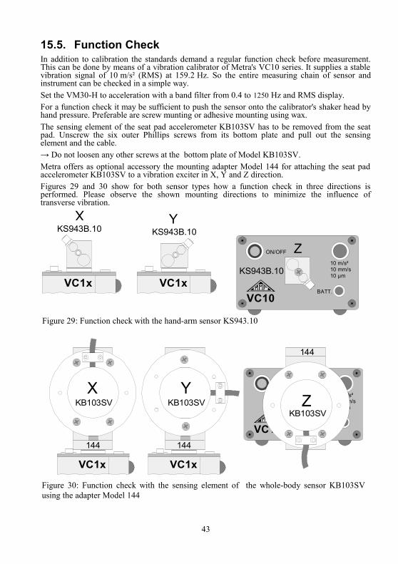
15.5. Function CheckIn addition to calibration the standards demand a regular function check before measurement. This can be done by means of a vibration calibrator of Metra's VC10 series. It supplies a stable vibration signal of 10 m/s² (RMS) at 159.2 Hz. So the entire measuring chain of sensor and instrument can be checked in a simple way. Set the VM30-H to acceleration with a band filter from 0.4 to 1250 Hz and RMS display.For a function check it may be sufficient to push the sensor onto the calibrator's shaker head by hand pressure. Preferable are screw munting or adhesive mounting using wax.The sensing element of the seat pad accelerometer KB103SV has to be removed from the seat pad. Unscrew the six outer Phillips screws from its bottom plate and pull out the sensing element and the cable. → Do not loosen any other screws at the bottom plate of Model KB103SV.Metra offers as optional accessory the mounting adapter Model 144 for attaching the seat pad accelerometer KB103SV to a vibration exciter in X, Y and Z direction.Figures 29 and 30 show for both sensor types how a function check in three directions is performed. Please observe the shown mounting directions to minimize the influence of transverse vibration.
43
Figure 29: Function check with the hand-arm sensor KS943.10
Y
X
VC1x VC1x
ON/OFF
10 m/s²10 mm/s10 µm
BATT.VC10
ZKS943B.10 KS943B.10
KS943B.10
ON/OFF
10 m/s²10 mm/s10 µm
BATT.VC10
ZYX
VC1xVC1x
KB103SV KB103SVKB103SV
144
144144
Figure 30: Function check with the sensing element of the whole-body sensor KB103SV using the adapter Model 144
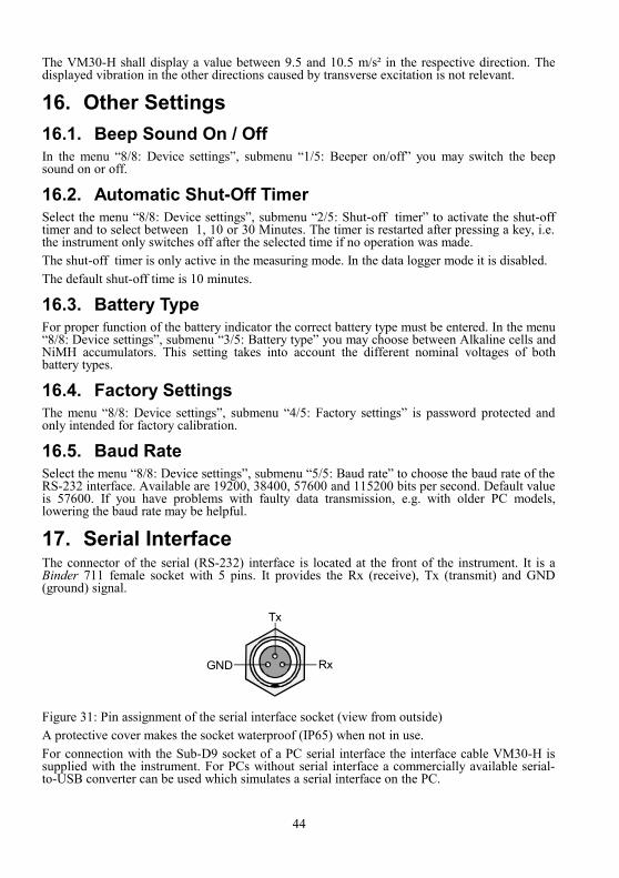
The VM30-H shall display a value between 9.5 and 10.5 m/s² in the respective direction. The displayed vibration in the other directions caused by transverse excitation is not relevant.
16. Other Settings 16.1. Beep Sound On / OffIn the menu “8/8: Device settings”, submenu “1/5: Beeper on/off” you may switch the beep sound on or off.
16.2. Automatic Shut-Off TimerSelect the menu “8/8: Device settings”, submenu “2/5: Shut-off timer” to activate the shut-off timer and to select between 1, 10 or 30 Minutes. The timer is restarted after pressing a key, i.e. the instrument only switches off after the selected time if no operation was made.The shut-off timer is only active in the measuring mode. In the data logger mode it is disabled.The default shut-off time is 10 minutes.
16.3. Battery TypeFor proper function of the battery indicator the correct battery type must be entered. In the menu “8/8: Device settings”, submenu “3/5: Battery type” you may choose between Alkaline cells and NiMH accumulators. This setting takes into account the different nominal voltages of both battery types.
16.4. Factory SettingsThe menu “8/8: Device settings”, submenu “4/5: Factory settings” is password protected and only intended for factory calibration.
16.5. Baud RateSelect the menu “8/8: Device settings”, submenu “5/5: Baud rate” to choose the baud rate of the RS-232 interface. Available are 19200, 38400, 57600 and 115200 bits per second. Default value is 57600. If you have problems with faulty data transmission, e.g. with older PC models, lowering the baud rate may be helpful.
17. Serial InterfaceThe connector of the serial (RS-232) interface is located at the front of the instrument. It is a Binder 711 female socket with 5 pins. It provides the Rx (receive), Tx (transmit) and GND (ground) signal.
Figure 31: Pin assignment of the serial interface socket (view from outside)A protective cover makes the socket waterproof (IP65) when not in use.For connection with the Sub-D9 socket of a PC serial interface the interface cable VM30-H is supplied with the instrument. For PCs without serial interface a commercially available serial-to-USB converter can be used which simulates a serial interface on the PC.
44
GND
Tx
Rx
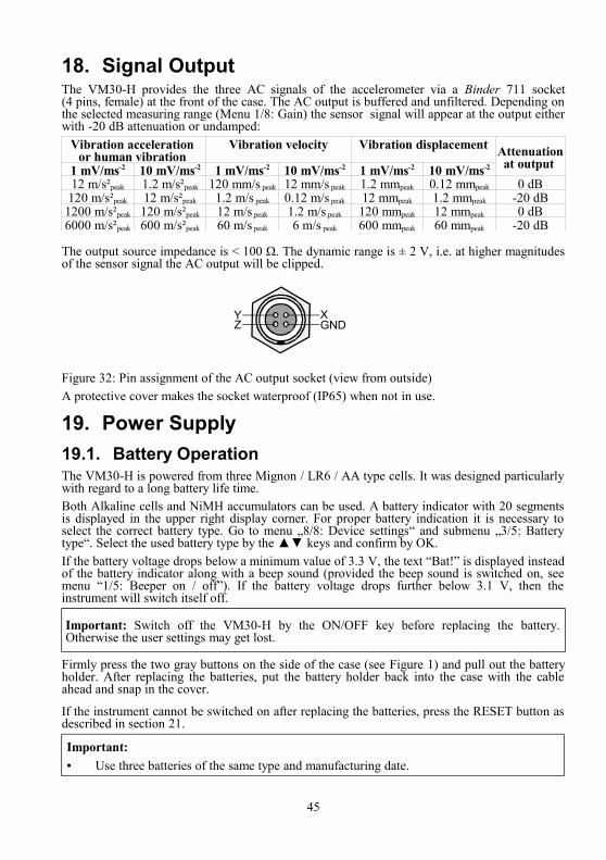
18. Signal OutputThe VM30-H provides the three AC signals of the accelerometer via a Binder 711 socket (4 pins, female) at the front of the case. The AC output is buffered and unfiltered. Depending on the selected measuring range (Menu 1/8: Gain) the sensor signal will appear at the output either with -20 dB attenuation or undamped:
Vibration acceleration or human vibration
1 mV/ms-2 10 mV/ms-2
Vibration velocity
1 mV/ms-2 10 mV/ms-2
Vibration displacement
1 mV/ms-2 10 mV/ms-2
Attenuation at output
12 m/s²peak 1.2 m/s²peak 120 mm/s peak 12 mm/s peak 1.2 mmpeak 0.12 mmpeak 0 dB120 m/s²peak 12 m/s²peak 1.2 m/s peak 0.12 m/s peak 12 mmpeak 1.2 mmpeak -20 dB
1200 m/s²peak 120 m/s²peak 12 m/s peak 1.2 m/s peak 120 mmpeak 12 mmpeak 0 dB6000 m/s²peak 600 m/s²peak 60 m/s peak 6 m/s peak 600 mmpeak 60 mmpeak -20 dB
The output source impedance is < 100 Ω. The dynamic range is ± 2 V, i.e. at higher magnitudes of the sensor signal the AC output will be clipped.
Figure 32: Pin assignment of the AC output socket (view from outside)A protective cover makes the socket waterproof (IP65) when not in use.
19. Power Supply19.1. Battery OperationThe VM30-H is powered from three Mignon / LR6 / AA type cells. It was designed particularly with regard to a long battery life time.Both Alkaline cells and NiMH accumulators can be used. A battery indicator with 20 segments is displayed in the upper right display corner. For proper battery indication it is necessary to select the correct battery type. Go to menu „8/8: Device settings“ and submenu „3/5: Battery type“. Select the used battery type by the ▲▼ keys and confirm by OK. If the battery voltage drops below a minimum value of 3.3 V, the text “Bat!” is displayed instead of the battery indicator along with a beep sound (provided the beep sound is switched on, see menu “1/5: Beeper on / off”). If the battery voltage drops further below 3.1 V, then the instrument will switch itself off.
Important: Switch off the VM30-H by the ON/OFF key before replacing the battery. Otherwise the user settings may get lost.
Firmly press the two gray buttons on the side of the case (see Figure 1) and pull out the battery holder. After replacing the batteries, put the battery holder back into the case with the cable ahead and snap in the cover.
If the instrument cannot be switched on after replacing the batteries, press the RESET button as described in section 21.
Important:• Use three batteries of the same type and manufacturing date.
45
ZY X
GND

• Be sure to insert the batteries with the correct polarity as stamped on the battery holder.• Replace discharged batteries immediately and remove the batteries if the instrument is
not used for an extended period. Otherwise leakage may cause irreversible damage.
Please use your local collection or recycling system for the disposal of batteries. Do not throw batteries into domestic waste.
19.2. External SupplyThe VM30-H can be supplied externally via a socket type Binder 711 (5 pins, female). The supply voltage range is 8 to 12 VDC with a current consumption below 200 mA. The voltage source must be able to supply a peak current of 1 A in the moment after switching on the VM30-H. The power supply input is protected against false polarization. Operation with external supply is indicated as “Ext.” instead of the battery indicator.Charging the internal batteries by an external supply voltage is not possible.
Figure 33: Pin assignment of the power supply socket (view from outside)A protective cover makes the socket waterproof (IP65) when not in use.
46
GNDUs Ext.
20. Loading Default SettingsThe instrument can be reset to the initial factory settings by choosing the menu item “6/8: Load defaults”. This effects:• Reset of the transducer sensitivities to 10.00 mV/ms-2
• Reload of the factory calibration values• Overwriting the user-defined setups with their default values (see section 9.4)• Reset of time and date• Reset of other variables like baud rate, beep sound, measuring range, shut-off timer and
battery type• Erasing the data memory
21. Hardware ResetIf the VM30-H should not start after longer storage without batteries, it may be necessary to reset the software. This can be done by pressing the RESET button which is located in the battery compartment (see Figure 3). After this it may be necessary to load the default settings as described in section 20. Please check also time and date.
22. Hardware and Firmware Versions The hardware and firmware versions of the VM30-H are coded as follows:
HH.FF.hhh.fff HH is the hardware version marking major hardware changes hhh is the hardware sub-version marking minor hardware changes FF is the firmware version marking major firmware changes fff is the firmware sub-version marking minor firmware changesYou may identify the hardware and firmware version when you press the INFO key.The complete version code including the sub-versions can be found in the menu "8/8: Device settings".
47

23. Questions and AnswersQuestion Answer
Why does the VM30-H display only one or two measuring values although I have connected a triaxial accelerometer?
The VM30-H recognizes open inputs and blanks the respective channels. Check the sensor connectors. Replace the cable or the sensor, if necessary. Note that only one value is displayed when measuring vibration total value Ahv.
The VM30-H displays continuously overload or invalid results.
Press the MENU key and select “6/8: Load defaults”. After this the transducer sensitivities from the calibration certificate, time and date must be entered again. Stored data and user-defined setups will be lost.
What can I do if the instrument cannot be switched on after replacing the batteries?
Press the Reset button behind the battery cover (Figure3). After this check time and date.
Why doesn’t the instrument display react to changes of the vibration magnitude after a longer measuring time in the interval RMS mode?
As a result of averaging over the entire measuring time do short vibration events not change significantly the displayed value.
What can I do if the Excel macro stops data transmission or receives invalid data?
Reduce the baud rate in the Excel worksheet „Import“ and in the VM30-H menu “8/8: Device settings”.
Why does the VM30-H ignore or change my settings of the measuring range?
You measure eVDV or interval RMS A(T): These display modes do not allow the use of autoranging. Channels with autoranging are set to the highest range. You measure vibration total value (Ahv): All three channels are automatically set to the highest one of the selected measuring ranges. When autoranging was selected, all channels are set to the highest range.
What can I do if the Excel macro displays the error message 1004 “Method ‘Columns’ … failed”?
Possibly you have activated one of the diagrams in the logger worksheets. Click one of the table fields instead.
The Excel macro displays "Not enough worksheets." when I import data from the VM30-H. How can I avoid this?
You have attempted to import more than 5 log files from the VM30-H. First make sure that you wanted to record log files but not single measurements in the manual mode. In the latter case data will appear in the “Manual” worksheet without limitation. The number of log files is limited by the number of prepared logfile worksheets. To increase this number you may add more worksheets. Then you will also have to change the number of logfiles in the Excel macro.
My instrument displays erroneous data instead of time, date and user-defined setups.
The instrument has been stored without batteries over a longer period. Perform a reset as described in chapter 21 and reload the default settings (chapter 20).
48

24. Technical DataMeasuring ranges with sensor 1mV/ms-2 Human vibration: Acceleration: Velocity: Displacement: with sensor 10mV/ms-2
Human vibration: Acceleration: Velocity: Displacement:
0.10-12.00 / 1.0-120.0* / 10-1200 / 100-6000 m/s²peak0.10-12.00 / 1.0-120.0* / 10-1200 / 100-6000 m/s²peak0.001-0.120 / 0.010-1.200 / 0.10-12.00 / 1.00-60.00 m/s peak0.001-0.120 / 0.010-1.200 / 0.10-12.00 / 1.00-60.00 mm peak
0.010-1.200 / 0.10-12.00* / 1.0-120.0 / 10-600 m/s²peak0.010-1.200 / 0.10-12.00* / 1.0-120.0 / 10-600 m/s²peak0.10-12.00 / 1.0-120.0 / 10-1200 / 100-6000 mm/s peak0.10-12.00 / 1.0-120.0 / 10-1200 / 100-6000 µm peak
Full-scale values valid only for frequencies where filter or integrator attenuation is 0 dB. * Reference range for calibration (chapter 15.3)
Accuracy: ± 3 % and ± 2 digits at reference conditionsLinearity error: < 5% of reading in all measuring rangesDisplay modes: Running RMS (1 s)
Maximum running RMS (MTVV)Interval RMS (up to 10 hours)Estimated vibration dose value (eVDV)Vibration total value (Ahv)Peak value (1 s)Maximum peak valueCrest factor
Weighting filters: Wb, Wc, Wd, We, Wg, Wh, Wj, Wk, Wm
Band filters (3 dB limits): 6 – 200 Hz (displacement)0.4 – 100 Hz (acceleration and velocity)2 – 300 Hz (acceleration and velocity)0.4 – 1250 Hz (acceleration and velocity)10 – 1250 Hz (acceleration and velocity)0.4 – 10 000 Hz (acceleration)1000 – 10 000 Hz (acceleration)The filters have 2nd order Butterworth characteristics.
Display: Graphical LCD with 32 x 120 dots and LED backlight3 vibration values with unit and mode
Sensor inputs: 3 IEPE inputs, socket type Binder 711, female, 4 pinsIEPE supply: 3 constant current sources, 2 mA, compliance voltage 20V
automatic sensor detectionmaximum input voltage: 6 V (peak-peak)
Transducer sensitivity: Nominal, adjustable 0.8 – 1.2 mV/ms-2
Nominal 10 mV/ms-2, adjustable 8 – 12 mV/ms-2
Recommended Accelerometers: KS943B.10 for Hand-Arm measurement (1 mV/ms-2)KB103SV-100 for whole-body measurement (10 mV/ms-2)
Cross-talk between X / Y / Z: < 0.5 % at ± 3 V input voltage, filter 0.4 – 10 000 HzSignal output: 3 AC sensor signals, buffered and unfiltered,
peak output voltage ± 2 V, output impedance < 100 ΩSocket type Binder 711, male, 4 pins
User-defined setups: 10 individually selectable parameter sets for vibration quantity, filter and display mode
49

Overload indication: Separately for each channel, at inputs and after integrators.Thresholds for measuring ranges:±1.2 mV / ±12 mV / ±120 mV / ±6 V
Memory: Flash memory for 1000 to 3000 measuring values, depending on the recording mode, optionally with time, date and comment
Recording modes: Manually by SAVE key orLogging, time controlled, time interval 1 second to 10 hours
Serial interface: Socket type Binder 711, female, 3 pinsBaud rates: 19200 / 38400 / 57600 / 115200Parity: even, data bits: 7, stop bits: 1
Batteries: 3 Alkaline cells or NiMH accumulators type IEC LR6 (Mignon)
Battery operating time: 15 to 25 hoursBattery indication: 20 segments, nominal battery voltage selectable, acoustical
low voltage warningExternal power supply: 8 to 12 V DC, < 200 mA, peak current: 1 A
socket type Binder 711, female, 5 pinsShut-off timer: After 1, 10, 30 minutes or no shut-offOperating temperature range: -10 to 50 °C, < 95 % relative humidity without condensationDeviation over temperature and humidity range:
Instrument: < ± 1 % of readingSensor KS943B.10: < ± 2 % of readingSensor KB103SV: < ± 3 % of reading
Protection grade: IP65 (protected against water jetting)Dimensions: 165 x 92 x 31 mm³Weight including batteries: 350 gSupplied accessories: VM30-I: RS-232 interface cable
with USB/RS-232 adapterOptional accessories: 034: Signal cable, 0.5 m, Binder 711 / 3 BNC
plugs KB103SV-100: Triaxial seat accelerometerKS943B.10: Triaxial accelerometer for hand-arm
measurement091: Cable for KS943B.10; 3 m140: Adapter for the fixation of the accelerometer
KS943B.10 on curved surfaces142: Hand-held adapter for the accelerometer
KS943B.10 on curved surfaces144: Calibration adapter for the seat accelerometer
KB103SV-100 Accessory kits: VM30-HA: Hand-arm kit
VM30-WB: Whole-body kitVM30HAWB: Hand-arm and whole-body kit
50

Limited Warranty
Metra warrants for a period of
24 months
that its products will be free from defects
in material or workmanship
and shall conform to the specifications
current at the time of shipment.
The warranty period starts with the date of invoice.
The customer must provide the dated bill of sale as evidence.
The warranty period ends after 24 months.
Repairs do not extend the warranty period.
This limited warranty covers only defects which arise as a result of normal use according to the instruction manual.
Metra’s responsibility under this warranty does not apply to anyimproper or inadequate maintenance or modification
and operation outside the product’s specifications.
Shipment to Metra will be paid by the customer. The repaired or replaced product will be sent back
at Metra’s expense.
51

52
Declaration of Conformity
Product: Human Vibration Meter
Model: VM30-H
It is hereby certified that the above mentioned product
complies with the demands pursuant to the following standards:
EN 55022: 1998
EN 55024: 1998
Responsible for this declaration is the producer
Manfred WeberMetra Mess- und Frequenztechnik in Radebeul e.K.
Meißner Str. 58
D-01445 Radebeul
Declared by
Michael Weber
Radebeul, May 4, 2006


![Vibration Energy Harvesting: Machinery Vibration, …...Vibration Energy Harvesting: Machinery Vibration, Human Move ment and Flow Induced Vibration 27 r ma P 4]Z 2 (3) where a Y Z2](https://img.dokumen.tips/doc/110x75/5e7c70af07fbe24a6e769fc0/vibration-energy-harvesting-machinery-vibration-vibration-energy-harvesting.jpg)