Embed Size (px)
Citation preview
HUMAN-LIKE SENSOR FUSION MECHANISMS IN A POSTURAL CONTROL ROBOT
Georg Hettich, Vittorio Lippi and Thomas Mergner Neurocenter, Neurological University Clinic, Breisacher Str. 64, 79106 Freiburg, Germany
Keywords: Sensor fusion, Postural control, Sensory Feedback, Humanoid Robot.
Abstract: In humans, maintaining body posture is a basis for many activities such as standing, walking or reaching. Human posture control involves multi-sensory integration mainly of joint angle, joint torque, vestibular and visual inputs. This integration provides humans with high flexibility and with robustness in terms of fail-safety. Roboticists may draw inspirations from the human control methods when building devices that interact with humans, such as prostheses or exoskeletons. This study presents a multisensory control method derived from human experiments, which is re-embodied in a biped postural control robot. The robot uses ankle and hip joints for balancing in the sagittal plane during external disturbances such as support surface motion. For the balancing, the robot estimates the external disturbances that have impact on its body by fusing the sensory signals. It then uses these estimates in negative feedback to command the local joint controls to compensate for the disturbances. This study describes the human sensor fusion mechanisms and their implementation into the robot, and it compares robot and human responses to support surface tilt. Measured balancing responses of the robot resemble in the main characteristics those of the human subjects, suggesting that the described sensor fusion mechanisms capture important aspects of human balancing.
1 INTRODUCTION
Sensors play a fundamental role in the sensorimotor behaviors of animals and humans. Use of sensors offloads computational burdens to the periphery and early processing stages of the central nervous system (CNS; e.g. Wehner, 1987). Furthermore, fusion of sensory data represents an important step in the perceptual reconstruction of the external world events having impact on the body (Mergner, 2002). Motion control of mechatronic systems, such as humanoid robots, still face many unsolved research problems, therefore roboticists show an increasing interest to unravel the human sensorimotor control, together with neuroscientists. This research aims to adopt principles from biological signal processing and sensorimotor control in humanoid robots, so that these can (i) show more human-like characteristics such as robustness in terms of fail-safety, versatility, and energy efficiency; (ii) show mechanical compliance to ensure safety in human-robot interactions; and (iii) serve as guidelines for
constructing medical devices such as neural prostheses and exoskeletons.
Neuroscientists often distinguish between proactive and reactive sensorimotor control. The term proactive refers to feed forward control of voluntary actions, dealing with foreseen or self-produced disturbances. The term reactive refers to sensory feedback control in response to unforeseen disturbances. A prototype of reactive control is balancing of upright posture during unforeseen external disturbances. Human control of this posture involves sensory feedback mainly from joint proprioception, vestibular system and vision (see Horak and MacPherson, 1996). The underlying neural sensor fusion mechanisms, often called multi-sensory integration, allow humans to adapt posture control to changes in the environment and to the availability of sensory information. Depending on the external conditions, the relative contributions of sensors to balance vary considerably, which has been called ‘sensory reweighting’ (Nashner and Berthoz, 1978; Peterka 2002; Mergner et al., 2003; Maurer et al., 2006; van der Kooij and Peterka, 2011). The sensory integration and reweighting

mechanisms are still the topic of on-going research. This paper presents a novel posture control concept that builds mainly on sensor fusion mechanisms and is currently implemented in a humanoid robot that balances even when subjected to changing external disturbances.
Previous bipedal robots that perform sensor fusion often used Kalman filters for multisensory integration (Tahboub and Mergner, 2007; Mahboobin et al., 2008; Klein et al., 2011). Corresponding simulation models of sensor fusion in the postural control also used Kalman filters (van der Kooij et al., 1999; Kuo, 2005). Common to these models is a ‘sensory integration center’ in which multiple sensory signals are combined with centrally generated information (‘efference copy’). The aim of combining this information is to find the most accurate sensory representation for a given environmental situation. These solutions were primarily inspired by the technical evolution rather than the biological evolution.
A different approach was used by Mergner and colleagues (Mergner et al., 2003; Maurer et al., 2006; Mergner, 2010). These authors investigated fusion of vestibular and proprioceptive sensory signals in human psychophysical experiments on self-motion perception using an open loop systems analysis approach. They found that humans use several processing steps to combine the signals, which originate from several sensory transducers and finally result in a few estimates of the external disturbances that have an impact on body posture. The underlying fusion mechanisms are rather simple, in that they don’t require use of a full dynamic model of human biomechanics and of iterative processing.
The inferred fusion mechanisms were then implemented into a stance control model, having in mind that normally a high congruency between perception and action exists (Mergner, 2002). In model simulation, a close correspondence between simulated and experimentally observed postural responses to external disturbances has then been observed (Mergner et al., 2003; Maurer et al., 2006). Noticeably, the implemented sensor fusion mechanisms provide a means for automatic sensory re-weightings and for reducing effects of sensory noise. The model was implemented and successfully tested so far on a 1 degree of freedom (DOF) robot with ankle joint actuation (Posturob I; Mergner et al., 2009).
The implementation of human-inspired posture control concepts in this robot mimics to a large extent the human balancing of moderate external
disturbances in the sagittal plane, which uses mainly the ankle joints (‘ankle strategy’; Nashner and McCollum, 1985; Horak and Nashner, 1986). The simplification of human biomechanics as a single inverted pendulum (SIP) was also helpful in modeling studies (e.g. Peterka, 2002). However, the SIP simplification is no longer applicable when humans use other joints in addition to the ankle joints, such as the hip joints, as one typically observes when strong transient disturbances are applied (‘hip strategy’; Nashner and McCollum, 1985; Horak and Nashner, 1986).
In this study we extend the human-inspired postural control model to deal with the double inverted pendulum (DIP) biomechanics of humans and a 2 DOF robot (hip and ankle joint). The focus is here, however, not so much on involving the hip joints during strong disturbances, but rather another aspect. During many activities such as walking, the secondary task ‘head stabilization in space’ is superimposed on the primary task of maintaining equilibrium using the ankle joints. This secondary task uses the hip joint to maintain a given trunk (and head) orientation in space to stabilize the workspaces of gaze, arms and hands and is thought to improve under dynamic conditions sensory feedback from the vestibular and visual cues arising in the head (Bronstein 1988; Pozzo et al. 1991).
In the following, a model of sensorimotor control is explained, which was used to interpret human SIP balancing responses around the ankle joints. Then the concept is extended to control a DIP by including the hip joints. The implementation of the control model into a humanoid robot and the comparison between robot and human subjects is described. In the final section, it is concluded that the human-inspired sensorimotor control concept can be used in the form of a modular control architecture for humanoid robots that are expected to show human-like characteristics when interacting with humans behaviorally or in the form of prostheses or exoskeletons.
2 METHODS
A model for controlling hip and ankle joint torques during balancing of external disturbances was developed using human-inspired sensor fusion mechanisms. These fusion mechanisms provide estimates of the external disturbances, which are used for disturbance compensation by feeding back the estimates rather than the raw sensory signals (disturbance estimation and compensation, DEC,
concept). First, the sensor fusion underlying the DEC concept will be briefly reviewed.
2.1 Basic aspects of sensor fusion in the DEC concept
The DEC concept involves essentially two steps of fusion. In the first step, information from several sensory transducers is fused to obtain measures of physical kinematic and kinetic variables. In the second step, these physical variables are combined to yield estimates of the external disturbances.
2.1.1 Sensory transducer data fusion
An example of the first step is the human sense of joint angle proprioception. It combines information from several sensory transducers such as muscle spindles, Golgi Tendon organs and cutaneous receptors (Gandevia et al., 2002). Also the human perception of head on trunk rotation is derived from such combinations, even with rotations across several segments of the cervical vertebral column. The result is a sense of angular head-on-trunk velocity and position, as if a rate sensor and a goniometer were measuring head-trunk rotation and speed about a single joint (Mergner et al., 1983; Mergner et al., 1991).
Another example for the first step, better known to engineers, is the fusion of angular and linear accelerometers in an inertial measuring unit (IMU). There is a problem with linear accelerometers, as they do not distinguish between inertial and gravitational forces (i.e. between linear acceleration and tilt of the sensor). There is also a problem with angular accelerometers (often used in the form of gyroscopes that measure angular velocity), as they show signal drifts over time. Both problems can be solved for the earth vertical planes by fusing the inputs from the two sensors in an appropriate way. This has an analogy in the human vestibular system that is located in the inner ears. Its otholith organs and canal systems represent biological equivalents of linear and angular accelerometers, respectively (Mergner et al., 2009). The canal-otolith and gyro-accelerometer fusions require information of the gravitational vector, however. Therefore, spatial orientation in the horizontal translational and rotational planes requires further information. In technical systems, often a Global Positioning System (GPS) is used. Humans usually use the visual system for this specific purpose.
In the following we will speak of joint angle and angular velocity sensors and mean corresponding
virtual sensors that result from step one. The same applies when we refer to the vestibular sensor and its three output measures, i.e. 3D angular velocity and linear acceleration in space and orientation with respect to the gravitational vertical. It is known from animal studies that neural signals coding local and global physical variables already exist in low processing levels of the CNS such as the spinal cord (Bosco and Poppele, 1997; Poppele et al., 2002). The measures of the physical variables represent the inputs to the second step of sensor fusion.
2.1.2 Disturbance estimation
In the second step, the signals of these variables are combined to reconstruct disturbances that have impact on the body. This step was motivated by reports of human subjects in the psychophysical experiments and by simple plausibility related to mechanics. An example from the psychophysical experiments is that a subject, asked to report his percept when passively turned on a rotation chair, is typically not reporting a sensation of head in space rotation stemming from the vestibular system, but a rotation of the chair, which is the underlying cause of the head rotation. Without being aware of it, the subject internally reconstructs the physical cause by using the vestibular head-in-space signal and combines it with proprioceptive information on the trunk rotation relative to the head, thereby obtaining the percept of trunk in space rotation, which during sitting is in haptic connection with the chair. This percept can formally be described in terms of a coordinate transformation by which the trunk is referenced to the vestibular derived notion of space (Mergner et al., 1997).
Another intuitive example of a reconstruction of an external disturbance by sensor fusion in step two concerns gravity as a field force. For field forces in general, it is known that subjects presented with a new aspect of a field force perceive and readily learn to counteract its impact on the body and then no longer perceive it consciously (Lackner and DiZio, 1994). Considering specifically gravity, during body lean it tends to accelerate the body away from the vertical. Stabilizing the body posture then requires a compensatory ankle torque. With small body excursions, this torque is proportional to the body COM angle in space. On the sensory side, the body lean is directly measured by the vestibular system. Knowing the vestibular signal, the body mass and the COM height, the gravitational ankle torque can be estimated and directly compensated. As before with the estimation of a rotation of the chair (support

surface), neck proprioceptive signals allow to reference the body lean to the vestibular notion of space.
Interestingly, it suffices to add to the just described two disturbances, i.e. to (a) support surface rotation and (b) field forces such as gravity, two more disturbances, which are (c) support surface translational acceleration and (d) contact forces such as a push or pull, in order to cover all the external disturbances that may have impact on the body during balancing. The latter two external disturbances also can be estimated by sensor fusion in simple, non-iterative ways (Mergner, 2010). Furthermore, it was shown that the four estimates may be implemented in a feedback control to compensate for the disturbances.
Implementation of both steps of sensory fusion into a feedback model is shown schematically in Figure 1. The figure shows that the first fusion step (Transducer Fusion) applies to two distinct feedback loop systems. In the lower loop of the scheme, it provides a kind of local state feedback in the form of a proprioceptive signal of joint angle. In addition, the first fusion step provides inputs to the upper loop system where the external disturbances are estimated using the second fusion step (Disturbance Estimation).
Figure 1: Simplified scheme of the Disturbance Estimation and Compensation (DEC) concept.
The lower loop in Figure 1 represents a short-
latency local mechanism for regulating a joint in the form of a simple ‘servo control’. It receives a voluntary input signal (Set Point Signal) of the desired joint position. The controller (with a proportional and a derivative factor; PD controller) provides the motor command that is transformed by the muscles (not shown) into joint torque. Passive stiffness and viscosity, stemming from intrinsic properties of the musculoskeletal system contribute a minor part to the joint torque (also not shown). Proprioceptive feedback, biomechanics, and controller values are adjusted to account for the moment of inertia of the plant such that the actual
displacement trajectory corresponds to the desired trajectory. Therefore, no feed forward of plant dynamics (e.g. through an inverse of plant dynamics) is required.
Noticeably, the P and D factors identified in human stance control experiments (Peterka, 2002; Alexandrov et al., 2005; Maurer et al., 2006) are surprisingly low. In a SIP scenario, they appear to be geared to the body mass m of the pendulum, the height h of the mass and gravitational acceleration g (mgh; P ≈ mgh; D ≈ mgh/4). The human identified values are only slightly higher than these values.
The upper loop in Figure 1 stands for a more time consuming feedback loop from the disturbance estimates (identified lumped time delay of both loop systems, ≈180 ms; Peterka, 2002; Maurer et al., 2006). The upper loop commands the servo loop to compensate the effects that the external disturbances have on the body (note that sign of upper loop is opposite to that of the disturbances). By this, for example, the gravitational torque in the SIP joint is compensated for, in that the corresponding estimate commands the servo accordingly. The loop gain (at the level of the controller) is raised by this additional feedback. However, this increase occurs only at the time of the disturbance and to the extent of its impact. Interestingly, the compensation applies even with superposition of several disturbances as well as with superposition of the disturbances with voluntary movements (Mergner et al., 2009).
It has been shown by comparisons between human data and model simulations that the DEC concept describes the human balancing in a variety of disturbance scenarios. This even applied when the model was implemented in a 1 DOF humanoid robot (PostuRob I), including human time delays, and was tested in the human laboratory (overview Mergner, 2010). These testings demonstrated that the control method is robust against real world problems such as inaccurate and noisy sensors, mechanical dead zones, etc.
2.2 Sensor fusion in hip and ankle joints
Current work on the DEC concept, described below, deals with the questions (1) how the disturbance estimates and their compensation might deal with the DIP biomechanics, (2) how the head/trunk stabilization task is achieved, (3) how inter-segmental coupling torques are dealt with, and (4) how movement synergies are generated in the DEC control. The approach proceeds from the assumption that the DEC concept is realized in a multi-
-
-
Disturbance Compensation
+
ExternalDisturbances
Proprioceptive Feedback
Controller Plant
DisturbanceEstimation
Set PointSignal Transducer
Fusion
segmental system in the form of a modular control architecture. By controlling each DOF with one DEC module, the whole control would be easily scalable to changes in the number of DOFs.
2.2.1 DIP biomechanics
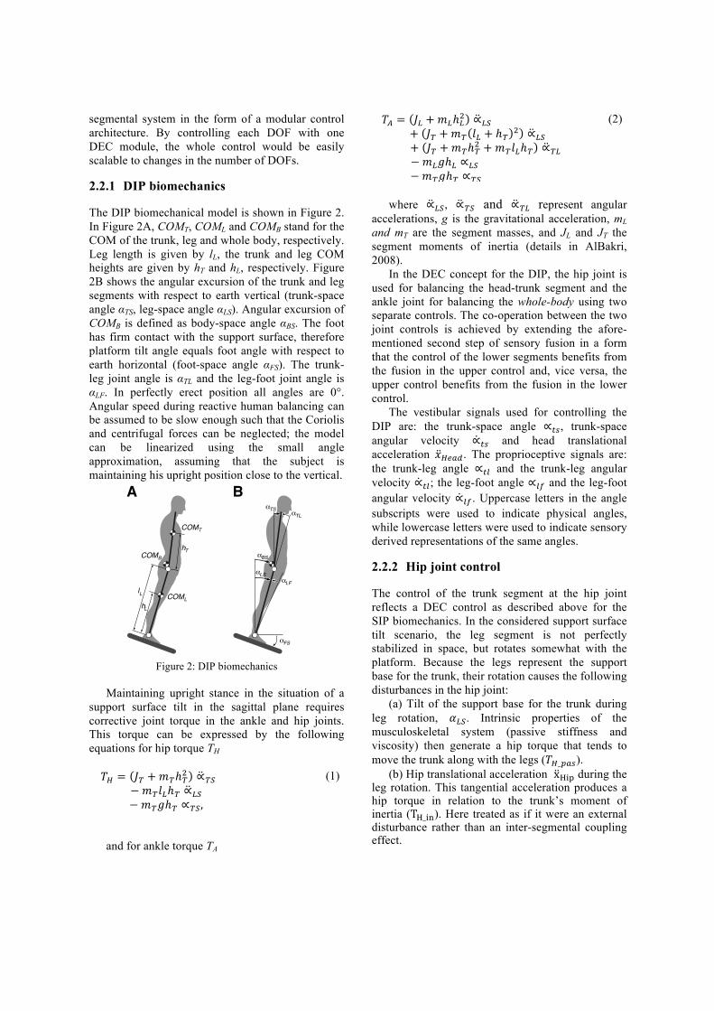
The DIP biomechanical model is shown in Figure 2. In Figure 2A, COMT, COML and COMB stand for the COM of the trunk, leg and whole body, respectively. Leg length is given by lL, the trunk and leg COM heights are given by hT and hL, respectively. Figure 2B shows the angular excursion of the trunk and leg segments with respect to earth vertical (trunk-space angle αTS, leg-space angle αLS). Angular excursion of COMB is defined as body-space angle αBS. The foot has firm contact with the support surface, therefore platform tilt angle equals foot angle with respect to earth horizontal (foot-space angle αFS). The trunk-leg joint angle is αTL and the leg-foot joint angle is αLF. In perfectly erect position all angles are 0°. Angular speed during reactive human balancing can be assumed to be slow enough such that the Coriolis and centrifugal forces can be neglected; the model can be linearized using the small angle approximation, assuming that the subject is maintaining his upright position close to the vertical.
Figure 2: DIP biomechanics
Maintaining upright stance in the situation of a
support surface tilt in the sagittal plane requires corrective joint torque in the ankle and hip joints. This torque can be expressed by the following equations for hip torque TH !! = !! +!!ℎ!! ∝!"!!!!!!!!!!!!!!!!!!!!!!!!!!!!!!!!!!
−!!!!ℎ! ∝!"!!!!!!!!!!!!!!!!!!!!!!!!!!!!−!!!ℎ! ∝!",!!!!!!!!!!!!!!!!!!!!!!!!!!!!!
(1)
and for ankle torque TA
!!! = !! +!!ℎ!! ∝!"!!!!!!!!!!!!!!!!!!!!!!!!!!!!!!!!!!!!!!+ !! +!! !! + ℎ! ! ∝!"!!!!!!+ !! +!!ℎ!! +!!!!ℎ! ∝!"−!!!ℎ! ∝!"!!!!!!!!!!!!!!!!!!!!!!!!!!!!!!!−!!!ℎ! ∝!"!!!!!!!!!!!!!!!!!!!!!!!!!!!!!!
(2)
where ∝!", ∝!" and ∝!" represent angular
accelerations, g is the gravitational acceleration, mL and mT are the segment masses, and JL and JT the segment moments of inertia (details in AlBakri, 2008).
In the DEC concept for the DIP, the hip joint is used for balancing the head-trunk segment and the ankle joint for balancing the whole-body using two separate controls. The co-operation between the two joint controls is achieved by extending the afore-mentioned second step of sensory fusion in a form that the control of the lower segments benefits from the fusion in the upper control and, vice versa, the upper control benefits from the fusion in the lower control.
The vestibular signals used for controlling the DIP are: the trunk-space angle ∝!", trunk-space angular velocity ∝!" and head translational acceleration !!"#$. The proprioceptive signals are: the trunk-leg angle ∝!" and the trunk-leg angular velocity ∝!"; the leg-foot angle ∝!" and the leg-foot angular velocity ∝!". Uppercase letters in the angle subscripts were used to indicate physical angles, while lowercase letters were used to indicate sensory derived representations of the same angles.
2.2.2 Hip joint control
The control of the trunk segment at the hip joint reflects a DEC control as described above for the SIP biomechanics. In the considered support surface tilt scenario, the leg segment is not perfectly stabilized in space, but rotates somewhat with the platform. Because the legs represent the support base for the trunk, their rotation causes the following disturbances in the hip joint:
(a) Tilt of the support base for the trunk during leg rotation, !!!. Intrinsic properties of the musculoskeletal system (passive stiffness and viscosity) then generate a hip torque that tends to move the trunk along with the legs (!!_!"#).
(b) Hip translational acceleration x!"# during the leg rotation. This tangential acceleration produces a hip torque in relation to the trunk’s moment of inertia (T!_!"). Here treated as if it were an external disturbance rather than an inter-segmental coupling effect.
B
L
BS
LF_
BS_
LS_
TS_TL_
FS_
A
B
Ll
Lh
Th
COML
COMT
COMB
(c) Gravitational hip torque (T!_!"#$) arises when the trunk is rotated off the vertical.
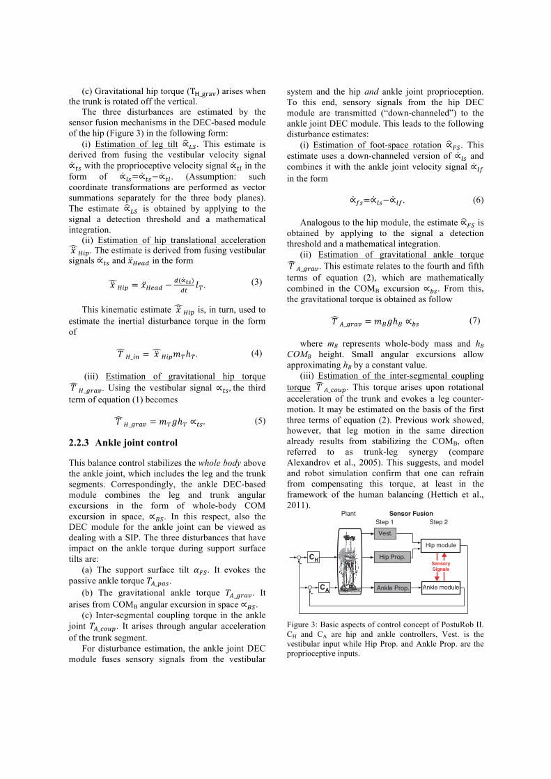
The three disturbances are estimated by the sensor fusion mechanisms in the DEC-based module of the hip (Figure 3) in the following form:
(i) Estimation of leg tilt ∝!". This estimate is derived from fusing the vestibular velocity signal ∝!" with the proprioceptive velocity signal ∝!" in the form of ∝!"=∝!"−∝!". (Assumption: such coordinate transformations are performed as vector summations separately for the three body planes). The estimate ∝!" is obtained by applying to the signal a detection threshold and a mathematical integration.
(ii) Estimation of hip translational acceleration !!!!"#. The estimate is derived from fusing vestibular signals ∝!" and !!"#$ in the form
!!!!"# = !!"#$ − !(∝!")
!" !!. (3)
This kinematic estimate !!!!"# is, in turn, used to
estimate the inertial disturbance torque in the form of
!!!!_!" = !!!!"#!!ℎ!. (4)
(iii) Estimation of gravitational hip torque
!!!!_!"#$. Using the vestibular signal ∝!",!the third term of equation (1) becomes
!!!!_!"#$ = !!!ℎ! ∝!". (5)
2.2.3 Ankle joint control
This balance control stabilizes the whole body above the ankle joint, which includes the leg and the trunk segments. Correspondingly, the ankle DEC-based module combines the leg and trunk angular excursions in the form of whole-body COM excursion in space, ∝!". In this respect, also the DEC module for the ankle joint can be viewed as dealing with a SIP. The three disturbances that have impact on the ankle torque during support surface tilts are:
(a) The support surface tilt !!". It evokes the passive ankle torque !!_!"#.
(b) The gravitational ankle torque !!_!"#$. It arises from COMB angular excursion in space ∝!".
(c) Inter-segmental coupling torque in the ankle joint !!_!"#$. It arises through angular acceleration of the trunk segment.
For disturbance estimation, the ankle joint DEC module fuses sensory signals from the vestibular
system and the hip and ankle joint proprioception. To this end, sensory signals from the hip DEC module are transmitted (“down-channeled”) to the ankle joint DEC module. This leads to the following disturbance estimates:
(i) Estimation of foot-space rotation ∝!". This estimate uses a down-channeled version of ∝!" and combines it with the ankle joint velocity signal ∝!" in the form
∝!"=∝!"−∝!" . (6)
Analogous to the hip module, the estimate ∝!" is
obtained by applying to the signal a detection threshold and a mathematical integration.
(ii) Estimation of gravitational ankle torque !!!!_!"#$. This estimate relates to the fourth and fifth terms of equation (2), which are mathematically combined in the COMB excursion ∝!". From this, the gravitational torque is obtained as follow
!!!!_!"#$ = !!!ℎ! ∝!" (7)
where mB represents whole-body mass and hB
COMB height. Small angular excursions allow approximating hB by a constant value.
(iii) Estimation of the inter-segmental coupling torque !!!!_!"#$. This torque arises upon rotational acceleration of the trunk and evokes a leg counter-motion. It may be estimated on the basis of the first three terms of equation (2). Previous work showed, however, that leg motion in the same direction already results from stabilizing the COMB, often referred to as trunk-leg synergy (compare Alexandrov et al., 2005). This suggests, and model and robot simulation confirm that one can refrain from compensating this torque, at least in the framework of the human balancing (Hettich et al., 2011).
Figure 3: Basic aspects of control concept of PostuRob II. CH and CA are hip and ankle controllers, Vest. is the vestibular input while Hip Prop. and Ankle Prop. are the proprioceptive inputs.
CA-
CH-
Vest.
Ankle Prop.
Hip Prop.SensorySignals
Hip module
Ankle module
PlantStep 1 Step 2
Sensor Fusion
The combination of the hip and ankle control modules and the mutual exchange of sensory information are shown schematically in Figure 3. Details of the “up-channeled” sensory information will be given in a forthcoming publication.
2.3 PostuRob II
The two-module control concept was implemented in PostuRob II. This robot consists of mechanical, mechatronic, and computer control parts. The mechanical part comprises one trunk segment, two legs and two feet, with a total mass of 59 kg and a total height of 1.78 m. Two hip joints and two ankle joints connect the segments (4 DOF in the sagittal plane; Figure 4). The mechatronic part comprises an artificial vestibular sensor (see Mergner et al., 2009) that is fixed to the trunk segment. Artificial pneumatic ‘muscles’ (FESTO, Esslingen, Germany; Typ MAS20) connected with serial springs (spring rate 25 N/mm) are used for actuation. An electronic inner torque control loop ensures that actual torque equals approximately desired torque. Sensory signals are sampled at 200 Hz via an acquisition board. Computer control is performed through a real time PC that executes a compiled Simulink model using Real-Time Windows Target (The Math Works Inc., Natick, USA).
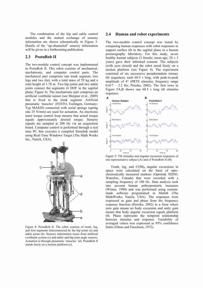
Figure 4: PostuRob II. The robot consists of trunk, leg, and foot segments interconnected by the hip joints (a) and ankle joints (b). Sensory information stems from artificial vestibular system (c) and ankle and hip joint angle sensors. Actuation is through pneumatic ‘muscles’ (d). PostuRob II stands freely on a motion platform (e).
2.4 Human and robot experiments
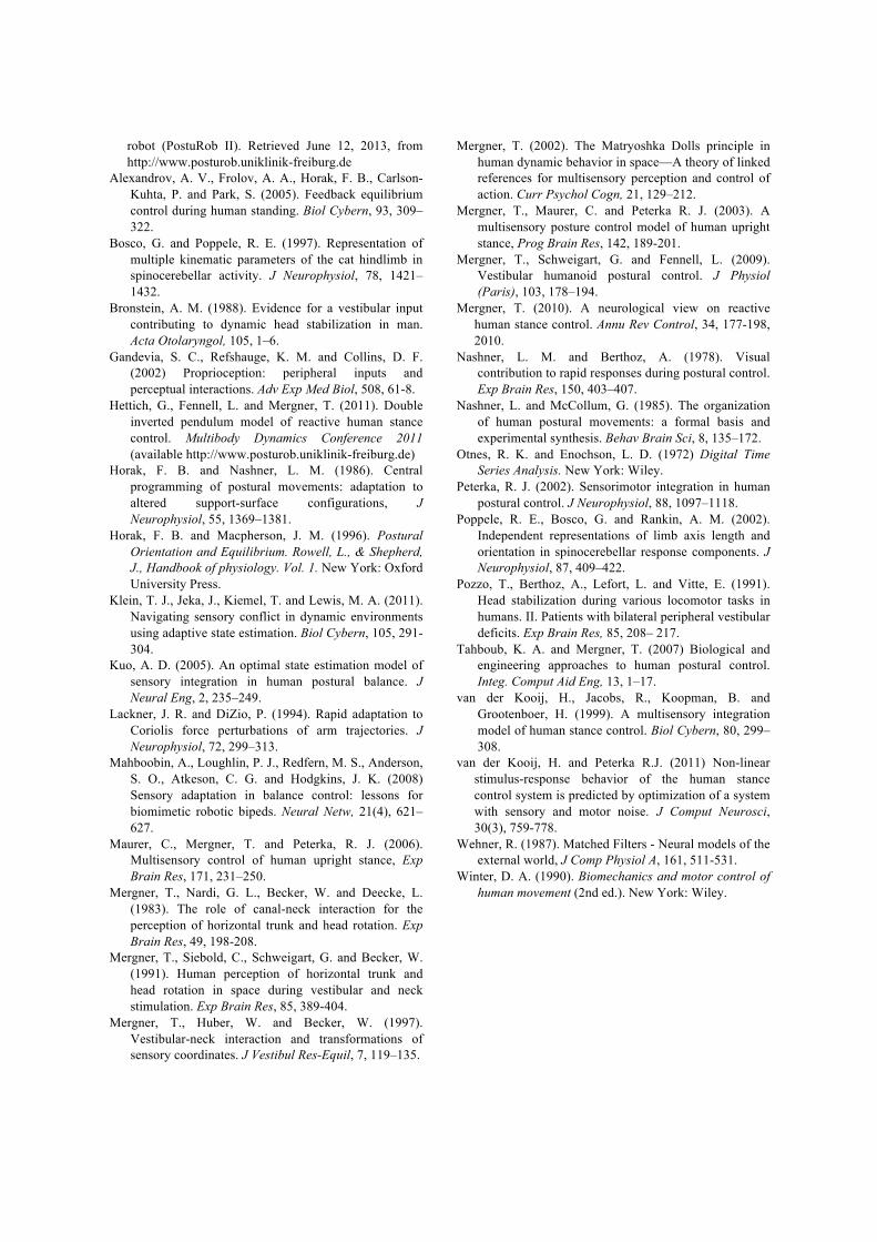
The two-module control concept was tested by comparing human responses with robot responses to support surface tilt in the sagittal plane in a human posturography laboratory. For this study, seven healthy human subjects (3 female; mean age, 28 ± 3 years) gave their informed consent. The subjects (with eyes closed) and the robot stood freely on a motion platform (see Figure 4). The experiment consisted of six successive pseudorandom ternary tilt sequences, each 60.5 s long, with peak-to-peak amplitude of 4° (PRTS stimulus; frequency range 0.017 – 2.2 Hz; Peterka, 2002). The first rows in Figure 5A,B shows one 60.5 s long tilt stimulus sequence.
Figure 5: Tilt stimulus and angular excursion responses of one representative subject (A) and of PostuRob II (B).
Trunk, leg, and COMB angular excursions in space were calculated on the basis of opto-electronically measured markers (Optotrak 3020®; Waterloo, Canada) that were recorded with a sampling frequency of 100 Hz. Data analysis took into account human anthropometric measures (Winter, 1990) and was performed using custom-made software programmed in Matlab (The MathWorks, Natick, USA). The responses were expressed as gain and phase from the frequency response function (Peterka, 2002) in a form where zero gain means no body excursion and unity gain means that body angular excursion equals platform tilt. Phase represents the temporal relationship between stimulus and response. Variability of averaged values was expressed as 95% confidence limits (Otnes and Enochson, 1972).
c
a
b
d
e
0 20 40 60
ï�
0
2
Angl
e (°
)
ï�
0
2
Angl
e (°
)
ï�
0
2An
gle
(°)
Time (s)0 20 40 60
ï�
0
2
ï�
0
2
ï�
0
2
Time (s)
Trunk-Space
Body-Space
Tilt Stimulus
Trunk-Space
Body-Space
Tilt Stimulus
AHuman Subject PostuRob II
B

3 RESULTS
Subjects and PostuRob II balance the support surface tilts in similar way. Time series of the responses of one subject and the robot are shown in Figure 5. Note that their responses are similar both for the body (COMB) and the trunk angles. The mean gain and phase curves are also very similar between the human subjects and the robot as it is shown in Fig. 6. The gain and phase values vary with stimulus frequency. In the low frequency range (< 0.3 Hz) trunk in space (TS) gain is lower than body in space (BS) gain. In the high frequency range (> 0.3 Hz) TS gain exceeds BS gain, while the phase shows a larger phase lag.
The good match of the data between the human subjects and PostuRob II suggests that the proposed sensor fusion mechanisms capture important aspects of human balancing.
Figure 6: Tilt responses in terms of gain, phase and coherence of human subjects (A) and PostuRob II (B).
4 CONCLUSIONS
The presented posture control system takes advantage of sensor fusion mechanisms derived from findings in human experiments. The sensor fusion proceeds in two steps. In the first step, sensory transducer signals are fused to obtain physical variables. In the second step, the physical variables are combined to estimate external disturbances. This is performed without integrating any dynamic model of the whole body in the control architecture.
Balancing upright stance using hip and ankle joints in terms of a DIP requires the integration of sensory signals from the whole body. For instance, to estimate a support surface tilt, the vestibular
information of head-space angular velocity (here in the absence of head-trunk excursions equivalent to trunk-space velocity ∝!") is fused with co-planar proprioceptive signals to obtain the angular speed of foot in space ∝!". This value is then integrated to obtain ∝!". Before the integration, ∝!" is filtered through a nonlinear operation, which is a deadband threshold. This works as a filtering system stabilizing the estimate ∝!" based on the noisy vestibular signal (Mergner et al., 2009). The threshold also explains the nonlinear responses of human subjects upon increase of the external disturbances (Maurer et al., 2006), which reflects an important aspect of the automatic sensory re-weighting. Another aspect is that the control automatically adjusts to changes in disturbance type and sensor availability (Mergner, 2010).
The presented sensor fusion system proved to be efficient enough to stabilize a humanoid robot in the presence of external disturbances. The control system based on this approach is modular in that it controls every joint as a SIP. Although optimizing the control parameters of the DEC concept is still a topic under research, the concept proved to have several promising features. These include: (i) a computationally very simple implementation, since almost all sensor fusions are based on algebraic operations; (ii) the control complexity scales linearly with the number of joints, since every joint is controlled as a SIP; (iii) noise rejection makes it possible to fuse the input of an high number of sensors; and lastly (iv) the system, originally proposed for its predictive power of human behaviour, can be employed to control actuated prostheses and exoskeletons to preserve a natural feeling in the user.
Future work comprises fusion of sensor-derived disturbance estimates with expected disturbance estimates and further validation of the concept by implementing it in a robot with a higher number of DOF.
ACKNOWLEDGEMENTS
Supported by the European Commission (FP7-ICT-600698 H2R).
REFERENCES
AlBakri, M. (2008). Development of a mathematical model and simulation environment for the postural
Gain
200
0
Phase(°)
Frequency (Hz)
0.01 0.1 1
0.01 0.1 1
A
TS
1
2
3
-200
0
Frequency (Hz)
0.01 0.1 1
0.01 0.1 1
B
1
2
3
BS
Human subjects PostuRob II
robot (PostuRob II). Retrieved June 12, 2013, from http://www.posturob.uniklinik-freiburg.de
Alexandrov, A. V., Frolov, A. A., Horak, F. B., Carlson-Kuhta, P. and Park, S. (2005). Feedback equilibrium control during human standing. Biol Cybern, 93, 309–322.
Bosco, G. and Poppele, R. E. (1997). Representation of multiple kinematic parameters of the cat hindlimb in spinocerebellar activity. J Neurophysiol, 78, 1421–1432.
Bronstein, A. M. (1988). Evidence for a vestibular input contributing to dynamic head stabilization in man. Acta Otolaryngol, 105, 1–6.
Gandevia, S. C., Refshauge, K. M. and Collins, D. F. (2002) Proprioception: peripheral inputs and perceptual interactions. Adv Exp Med Biol, 508, 61-8.
Hettich, G., Fennell, L. and Mergner, T. (2011). Double inverted pendulum model of reactive human stance control. Multibody Dynamics Conference 2011 (available http://www.posturob.uniklinik-freiburg.de)
Horak, F. B. and Nashner, L. M. (1986). Central programming of postural movements: adaptation to altered support-surface configurations, J Neurophysiol, 55, 1369–1381.
Horak, F. B. and Macpherson, J. M. (1996). Postural Orientation and Equilibrium. Rowell, L., & Shepherd, J., Handbook of physiology. Vol. 1. New York: Oxford University Press.
Klein, T. J., Jeka, J., Kiemel, T. and Lewis, M. A. (2011). Navigating sensory conflict in dynamic environments using adaptive state estimation. Biol Cybern, 105, 291-304.
Kuo, A. D. (2005). An optimal state estimation model of sensory integration in human postural balance. J Neural Eng, 2, 235–249.
Lackner, J. R. and DiZio, P. (1994). Rapid adaptation to Coriolis force perturbations of arm trajectories. J Neurophysiol, 72, 299–313.
Mahboobin, A., Loughlin, P. J., Redfern, M. S., Anderson, S. O., Atkeson, C. G. and Hodgkins, J. K. (2008) Sensory adaptation in balance control: lessons for biomimetic robotic bipeds. Neural Netw, 21(4), 621–627.
Maurer, C., Mergner, T. and Peterka, R. J. (2006). Multisensory control of human upright stance, Exp Brain Res, 171, 231–250.
Mergner, T., Nardi, G. L., Becker, W. and Deecke, L. (1983). The role of canal-neck interaction for the perception of horizontal trunk and head rotation. Exp Brain Res, 49, 198-208.
Mergner, T., Siebold, C., Schweigart, G. and Becker, W. (1991). Human perception of horizontal trunk and head rotation in space during vestibular and neck stimulation. Exp Brain Res, 85, 389-404.
Mergner, T., Huber, W. and Becker, W. (1997). Vestibular-neck interaction and transformations of sensory coordinates. J Vestibul Res-Equil, 7, 119–135.
Mergner, T. (2002). The Matryoshka Dolls principle in human dynamic behavior in space—A theory of linked references for multisensory perception and control of action. Curr Psychol Cogn, 21, 129–212.
Mergner, T., Maurer, C. and Peterka R. J. (2003). A multisensory posture control model of human upright stance, Prog Brain Res, 142, 189-201.
Mergner, T., Schweigart, G. and Fennell, L. (2009). Vestibular humanoid postural control. J Physiol (Paris), 103, 178–194.
Mergner, T. (2010). A neurological view on reactive human stance control. Annu Rev Control, 34, 177-198, 2010.
Nashner, L. M. and Berthoz, A. (1978). Visual contribution to rapid responses during postural control. Exp Brain Res, 150, 403–407.
Nashner, L. and McCollum, G. (1985). The organization of human postural movements: a formal basis and experimental synthesis. Behav Brain Sci, 8, 135–172.
Otnes, R. K. and Enochson, L. D. (1972) Digital Time Series Analysis. New York: Wiley.
Peterka, R. J. (2002). Sensorimotor integration in human postural control. J Neurophysiol, 88, 1097–1118.
Poppele, R. E., Bosco, G. and Rankin, A. M. (2002). Independent representations of limb axis length and orientation in spinocerebellar response components. J Neurophysiol, 87, 409–422.
Pozzo, T., Berthoz, A., Lefort, L. and Vitte, E. (1991). Head stabilization during various locomotor tasks in humans. II. Patients with bilateral peripheral vestibular deficits. Exp Brain Res, 85, 208– 217.
Tahboub, K. A. and Mergner, T. (2007) Biological and engineering approaches to human postural control. Integ. Comput Aid Eng, 13, 1–17.
van der Kooij, H., Jacobs, R., Koopman, B. and Grootenboer, H. (1999). A multisensory integration model of human stance control. Biol Cybern, 80, 299–308.
van der Kooij, H. and Peterka R.J. (2011) Non-linear stimulus-response behavior of the human stance control system is predicted by optimization of a system with sensory and motor noise. J Comput Neurosci, 30(3), 759-778.
Wehner, R. (1987). Matched Filters - Neural models of the external world, J Comp Physiol A, 161, 511-531.
Winter, D. A. (1990). Biomechanics and motor control of human movement (2nd ed.). New York: Wiley.