Embed Size (px)
Citation preview

Huawei OptiX OSN 9800 and Boards Datasheet

Router-switch.com 1
CONTENT
Overview .......................................................................................................................................................................... 2
Specification ..................................................................................................................................................................... 4
Services and Capabilities ................................................................................................................................................ 17
Hardware Description ..................................................................................................................................................... 34
OptiX OSN 9800 UPS Chassis ................................................................................................................................... 34
OptiX OSN 9800 M24 Chassis .................................................................................................................................. 36
OptiX OSN 9800 P32 Chassis ................................................................................................................................... 42
OptiX OSN 9800 U16 Chassis ................................................................................................................................... 48
OptiX OSN 9800 U32 Chassis ................................................................................................................................... 51
OptiX OSN 9800 U64 Chassis ................................................................................................................................... 54
Board Description ........................................................................................................................................................... 58
Basic Ordering Information............................................................................................................................................. 65
Where to Buy ................................................................................................................................................................. 66
Sources........................................................................................................................................................................... 67
Contact Us
Tel: +1-626-239-8066 (USA) +852-3050-1066 / +852-3174-6166
Fax: +852-3050-1066 (Hong Kong)
Email: [email protected] (Sales Inquiries)

Router-switch.com 2
Overview
Intended for 100G and beyond 100G optical networks, the Huawei OSN 9800 U64/U32/U16 subrack is a next-generation
large-capacity OTN product that integrates ASON, OTN, and packet functions. It is applicable to various networks,
including super-backbone, backbone, and metro networks.
OSN 9800 M24 is a next-generation ultra-large capacity, high integration, and optoelectronic OTN/WDM product
developed based on new software and hardware platforms. It is applicable to backbone and metro networks.
OSN 9800 universal platform subrack mainly works with the OSN 9800 U64/U32/U16/M24, which is applied at the
electrical layer in WDM and OTN system. Empowered with these features, OSN 9800 universal platform subrack enables
end-to-end OTN/WDM backbone transport solutions and implements multi-service, large-capacity, and fully transport
transmission.
The OSN 9800 P32 subrack is an ultra-large capacity all-optical cross-connect product. It is mainly used at the backbone
core layer and metro aggregation layer. It works with the OSN 9800/1800 to build a complete E2E WDM/OTN backbone
transmission solution, achieving transparent and ultra-large capacity transmission.
OptiX OSN 9800 UPS OptiX OSN 9800 M24 OptiX OSN 9800 P32

Router-switch.com 3
Role of the OptiX OSN 9800 in a network-wide solution
OptiX OSN 9800 U16 OptiX OSN 9800 U32 OptiX OSN 9800 U64

Router-switch.com 4
Hybrid networking with OptiX OSN 9800 and OptiX OSN 8800/6800
Specification
Table 1. Specification of OSN 9800 U64/U32/U16
Specifications OSN 9800
U64 Standard
OSN 9800
U32 Standard
OSN 9800 U16 OSN 9800 U64
Enhanced
OSN 9800
U32
Enhanced
Subrack dimensions (mm) 2200 (H) x 600
(W) x 600 (D)
(the subrack is
1900 (H) x 498
(W) x 295 (D)
847 mm (H) x
442 mm (W) x
295 mm (D)
2200 (H) x 600
(W) x 600 (D)
(the subrack is
1900 (H) x
498 (W) x
295 (D)

Router-switch.com 5
integrated into a
cabinet)
(without
cabinet)
(without
cabinet)
integrated
into a cabinet)
(without
cabinet)
Suitable cabineta The subrack is
integrated into a
cabinet, and no
additional
cabinet needs to
be configured.
ETSI 300/600
cabinets, such
as N63B and
N66B
ETSI 300/600
cabinets, such
as N63B and
N66B
19-inch cabinet
The subrack is
integrated
into a cabinet,
and no
additional
cabinet needs
to be
configured.
ETSI
300/600
cabinets,
such as
A63B
Number of slots for service
boards
64 32 14 64 32
Switching
capability
Optical N/A
Electrical 25.6 Tbit/s ODUk
(k = 0, 1, 2, 2e, 3,
4, flex)
12.8 Tbit/s
packet services
10.24 Tbit/s VC-4
160 Gbit/s VC-
3/VC-12
12.8 Tbit/s
ODUk (k = 0, 1,
2, 2e, 3, 4, flex)
6.4 Tbit/s
packet services
5.12 Tbit/s VC-
4
160 Gbit/s VC-
3/VC-12
5.6 Tbit/s ODUk
(k = 0, 1, 2, 2e,
3, 4, flex)
2.8 Tbit/s
packet services
1.12 Tbit/s VC-4
80 Gbit/s VC-
3/VC-12
64 Tbit/s
ODUk (k = 0,
1, 2, 2e, 3, 4,
flex)
12.8 Tbit/s
packet
services
10.24 Tbit/s
VC-4
160 Gbit/s VC-
3/VC-12
32 Tbit/s
ODUk (k =
0, 1, 2, 2e,
3, 4, flex)
6.4 Tbit/s
packet
services
5.12 Tbit/s
VC-4
160 Gbit/s
VC-3/VC-
12
Max. number of
wavelengths
Fixed grid: 96 wavelengths @50 GHz grid
Flexible grid: The maximum number of wavelengths is related to the width of the flex
channel.

Router-switch.com 6
Center wavelength range DWDM system: 1529.16 nm to 1567.13 nm (extend C-band, ITU-T G.694.1)
Max. rate per channel 400 Gbit/s (OTUC4)
Service type Synchronous digital hierarchy (SDH)/synchronous optical network (SONET), Ethernet,
storage area network (SAN), optical transport network (OTN), and video
Packet service capacity Support E-Line/E-LAN (MEF) and VPWS/VPLS (IETF)
Support MPLS-TP
Number of MPLS tunnel: 64x1024
Number of PW: 64x1024
Number of E-Line: 32x1024
Number of E-LAN: 8x1024
Line rate 10 Gbit/s, 40 Gbit/s, 100 Gbit/s, 200 Gbit/s and 400
Gbit/s
10 Gbit/s, 100 Gbit/s, 200
Gbit/s and 400 Gbit/s
Supported pluggable
optical modules
eSFP, SFP+, XFP, CFP, CXP, CFP2, QSFP28 eSFP, SFP+, CFP, CFP2,
QSFP28
Topology Point-to-point, chain, star, ring, ring-with-chain, tangent ring, intersecting ring, and
mesh
Redundancy
and
protection
Equipment
level
protection
Power redundancy, fan redundancy, cross-connect board redundancy,
communication control and clock processing unit redundancy
Network
level
protection
(OTN)
Client 1+1 protection, ODUk SNCP, tributary SNCP,
intra-board 1+1 protection, LPT, Port-level M:N
protection
Client 1+1 protection, ODUk
SNCP, tributary SNCP, intra-
board 1+1 protection, LPT

Router-switch.com 7
Network
level
protection
(Packet)
ERPS, LAG, MC-LAG, LMSP, MC-LMSP, MRPS, PW APS,
MC-PW APS, Tunnel APS, LPT
LAG, PW APS, Tunnel APS
Network
level
protection
(OCS)
LMSP, SNCP, Ring MSP
Optical power
management
ALS, IPA, IPA of Raman System
Synchronization Synchronous Ethernet clock
IEEE 1588v2
ITU-T G.8275.1
ASON Electrical-Layer ASON
TSDN Online Service Provisioning
Survivability Analysis
BOD
IP and Optical Collaboration
Submarine features Supports application of extended C band in submarine scenarios.
Nominal working voltage Nominal working voltage: -48V DC/-60V DC
Working voltage range:
-48 V DC: -40 V to -57.6 V
-60 V DC: -48 V to -72 V

Router-switch.com 8
Operation environment Subrack temperature:
Long-term operation: 5°C (41 °F) to
40°C (104 °F)
Short-term operationb: -5°C (23 °F)
to 45°C (113 °F)
Relative humidity:
Long-term operation: 5% to 85%
Short-term operationb: 5% to 90%
Subrack
temperature:
Long-term
operation: 5°C
(41 °F) to 40°C
(104 °F)
Short-term
operationb: -5°C
(23 °F) to 50°C
(122 °F)
Relative
humidity:
Long-term
operation: 5%
to 85%
Short-term
operationb: 5%
to 90%
Subrack temperature:
Long-term operation: 5°C
(41 °F) to 40°C (104 °F)
Short-term operationb: -5°C
(23 °F) to 45°C (113 °F)
Relative humidity:
Long-term operation: 5% to
85%
Short-term operationb: 5%
to 90%
Mean Time To Repair
(MTTR)
4 hours
Mean Time Between
Failure (MTBF)
66.83 years
a: The ETSI/19-inch standard defines only part of the cabinet dimensions. Therefore, the distance between the
cabinet column and door plate varies depending on cabinet manufacturers. For details about the dimensions of
different subracks, see the detailed description of each subrack.
b: Short-term operation means that the continuous operating time does not exceed 96 hours and the accumulated
time per year does not exceed 15 days.

Router-switch.com 9
Table 2. Specification of OSN 9800 M24
Specifications OSN 9800 M24
Subrack dimensions (mm) 747.2 mm (H) x 442 mm (W) x 295 mm (D)
Suitable cabineta ETSI 300/600 cabinets, such as A63B
19-inch cabinet
Number of slots for service
boards
1:1 cross-connect mode: 12 large slots or 24 small slots
1:3 cross-connect mode: 10 large slots or 20 small slots
NOTE:
The M24 subrack supports slot splitting. One 11 U slot of the M24 subrack can
be split into two 5.5 U slots.
Switching
capability
Electrical 1:1 cross-connect mode:
4.8 Tbit/s ODUk
2.4 Tbit/s packet services
1.92 Tbit/s VC-4
80 Gbit/s VC-3/VC-12
1:3 cross-connect mode:
10 Tbit/s ODUk
2 Tbit/s packet services
1.6 Tbit/s VC-4
80 Gbit/s VC-3/VC-12
Max. number of wavelengths Fixed grid: 96 wavelengths @50 GHz grid

Router-switch.com 10
Flex grid: The maximum number of wavelengths is related to the width of the
flex channel.
Wavelength range 1529.16 nm-1567.13 nm (extended C-band, ITU-T G.694.1)
Max. rate per channel 400G bit/s (OTUC4)
Service type Synchronous digital hierarchy (SDH)/synchronous optical network (SONET),
Ethernet, SAN, OTN, video
Packet service capacity Support E-Line/E-LAN (MEF) and VPWS/VPLS (IETF)
Support MPLS-TP
Number of MPLS tunnel: 64x1024
Number of PW: 64x1024
Number of E-Line: 32x1024
Number of E-LAN: 8x1024
Line rate 10Gbit/s, 100 Gbit/s, 200G bit/s, 400G bit/s
Supported pluggable optical
modules
eSFP, SFP+, TSFP+, CFP, CFP2, QSFP28
Topology Point-to-point, chain, star, ring, ring-with-chain, tangent ring, intersecting ring,
and mesh
Redundancy
and
protection
Network level
protection (OTN)
Client 1+1 protection, ODUk SNCP, tributary SNCP, intra-board 1+1 protection,
LPT
Network level
protection
(Packet)
LAG, PW APS, Tunnel APS
Network Level
Protection (OCS)
LMSP, SNCP, Ring MSP

Router-switch.com 11
Equipment level
protection
Power redundancy, fan redundancy, cross-connect board redundancy,
communication control and clock processing unit redundancy
Synchronization Synchronous Ethernet, IEEE 1588v2, ITU-T G.8275.1/G.8273.2
ASON Electrical-Layer ASON
TSDN Online Service Provisioning
Survivability Analysis
BOD
IP and Optical Collaboration
Power Supply Nominal working voltage: -48V DC/-60V DC
Working voltage range:
-48 V DC: -40 V to -57.6 V
-60 V DC: -48 V to -72 V
Operation environment Subrack temperature:
Long-term operation: 0°C to 45°C;
Short-term operationb: -5°C to 50°C
Relative humidity:
Long-term operation: 5% to 85%
Short-term operationb: 5% to 90%
Mean Time To Repair (MTTR) 4 hours
Mean Time Between Failure
(MTBF)
66.89 years

Router-switch.com 12
a: The ETSI/19-inch standard defines only part of the cabinet dimensions. Therefore, the distance between the
cabinet column and door plate varies depending on cabinet manufacturers. For details about the dimensions of
different subracks, see the detailed description of each subrack.
b: Short-term operation means that the continuous operating time does not exceed 96 hours and the accumulated
time per year does not exceed 15 days.
Table 3. Specification of OSN 9800 UPS
Specifications OSN 9800 Universal Platform Subrack
Subrack dimensions (mm) 397 mm (H) x 442 mm (W) x 295 mm (D) (without cabinet)
Suitable cabineta ETSI 300/600 cabinets, such as N63B and N66B
19-inch cabinet
Number of slots for service boards DC power supply: 16
AC power supply: 15
Switching
capability
Optical 1 to 20-degree reconfigurable optical add/drop multiplexer (ROADM)
Electrical N/A
Max. number of wavelengths Fixed grid: 96 wavelengths @50 GHz grid
Flex grid: The maximum number of wavelengths is related to the width
of the flex channel.
Center wavelength range DWDM system: 1529.16 nm to 1567.13 nm (extend C-band, ITU-T
G.694.1)
Max. rate per channel 400 Gbit/s (OTUC4)
Service type Synchronous digital hierarchy (SDH)/ synchronous optical network
(SONET), Ethernet, storage area network (SAN), optical transport
network (OTN), and video

Router-switch.com 13
Packet service capacity N/A
Line rate 2.5 Gbit/s, 10 Gbit/s, 40 Gbit/s, 100 Gbit/s, 200 Gbit/s, 400 Gbit/s
Supported pluggable optical modules eSFP, SFP+, XFP, CFP, CFP2, QSFP28, QSFP+
Topology Point-to-point, chain, star, ring, ring-with-chain, tangent ring,
intersecting ring, and mesh
Redundancy and
protection
Equipment level
protection
Power redundancy, fan redundancy, system control and
communication board redundancy
Network level
protection (OTN)
Optical line protection, client 1+1 protection, SW SNCP, intra-board
1+1 protection, LPT
Network Level
Protection (Packet)
N/A
Network Level
Protection (OCS)
N/A
Optical power management ALS, AGC, ALC, APE, IPA, IPA of Raman System
Easy O&M Optical Doctor System(OD), Fiber Doctor System
Synchronization Synchronous Ethernet clock
IEEE 1588v2
ITU-T G.8275.1
ASON Optical-Layer ASON
TSDN N/A
Submarine Features Supports application of extended C band in submarine scenarios.
Power Supply DC Power Supply:

Router-switch.com 14
Nominal working voltage: -48V DC/-60V DC
Working voltage range:
-48V DC: -40V to -57.6V
-60V DC: -48V to -72V
AC Power Supply:
Nominal working voltage: 110V AC/220V AC
Working voltage range: 90 V to 290 V
Operation Environment Subrack temperature:
Long-term operation: 5°C (41 °F) to 45°C (113 °F)
Short-term operationa: -5°C (23 °F) to 55°C (131 °F)
Relative humidity:
Long-term operation: 5% to 85%
Short-term operationa: 5% to 95%
Mean Time To Repair (MTTR) 4 hours
Mean Time Between Failure (MTBF) 50 years
a: The ETSI/19-inch standard defines only part of the cabinet dimensions. Therefore, the distance between the
cabinet column and door plate varies depending on cabinet manufacturers. For details about the dimensions of
different subracks, see the detailed description of each subrack.
b: Short-term operation means that the continuous operating time does not exceed 96 hours and the accumulated
time per year does not exceed 15 days.

Router-switch.com 15
Table 4. Specification of OSN 9800 P32
Specifications OSN 9800 P32
Subrack dimensions (mm) 1390 (H) x 496 (W) x 315 (D) (without cabinet)
Suitable cabinet ETSI 300 cabinets, such as A63B
Number of slots for service boards 32
Switching capability Optical 1 to 32-degree reconfigurable optical add/drop multiplexer
(ROADM)
Electrical N/A
Max. number of wavelengths Fixed grid: 96 wavelengths @50 GHz grid
Flex grid: The maximum number of wavelengths is related to the
width of the flex channel.
Channel spacing Fixed grid: 50 GHz grid/100 GHz grid
Flex grid: Supports channel spacing designs, and the minimum can
be set to 6.25 GHz.
Center wavelength range DWDM system: 1529.16 nm to 1567.13 nm (extend C-band, ITU-T
G.694.1)
Topology Point-to-point, chain, star, ring, ring-with-chain, tangent ring,
intersecting ring, and mesh
Redundancy and
protection
Network level
protection
Optical line protection
Equipment level
protection
Power redundancy, fan redundancy, communication control and
clock processing unit redundancy
Optical power management IPA

Router-switch.com 16
Easy O&M Optical Doctor System (OD), Fiber Doctor System (FD)
Synchronization Synchronous Ethernet clock
IEEE 1588v2
ITU-T G.8275.1
Power Supply Nominal working voltage:
-48V DC/-60V DC
Working voltage range:
-48 V DC: -40 V to -57.6 V
-60 V DC: -48 V to -72 V
Operation environment Subrack temperature:
Long-term operation: 5°C (41°F) to 40°C (104°F)
Short-term operationba: -5°C (23°F) to 45°C (113°F)
Relative humidity:
Long-term operation: 5% to 85%
Short-term operationa: 5% to 90%
Mean Time To Repair (MTTR) 4 hours
Mean Time Between Failure (MTBF) 64.37 years
a: Short-term operation means that the continuous operating time does not exceed 96 hours and the accumulated
time per year does not exceed 15 days.

Router-switch.com 17
Services and Capabilities
Table 5. Service types, service rates, and corresponding service boards supported by the OptiX OSN 9800 U64/U32/U16
Subrack.
Service
Category
Service Type Service Rate Board Standard
Compliance
SDH STM-1 155.52 Mbit/s T130, T210, T220, T230, EC116, S216 ITU-T G.707
ITU-T G.691
ITU-T G.957
ITU-T G.693
ITU-T G.783
ITU-T G.825
STM-4 622.08 Mbit/s T130, T210, T220, T230, EC404, S216
STM-16 2.5 Gbit/s T130, T210, T220, T230, S216
STM-64 9.95 Gbit/s T216, T210, T220, T230, G210, G220,
S208, S216
STM-256 39.81 Gbit/s T302
SONET OC-3 155.52 Mbit/s T130, T210, T220, T230 GR-253-CORE
GR-1377-CORE
ANSI T1.105
OC-12 622.08 Mbit/s T130, T210, T220, T230
OC-48 2.5 Gbit/s T130, T210, T220, T230
OC-192 9.95 Gbit/s T216, T210, T220, T230, G210, G220
OC-768 39.81 Gbit/s T302
Ethernet
service
FE (optical
signal)
Interface rate: 125
Mbit/s
Service rate: 100
Mbit/s
T130, T210, T220, T230, T220E, E124,
E224
IEEE 802.3u
FE (electrical
signal)
Interface rate: 125
Mbit/s
E124

Router-switch.com 18
Service rate: 100
Mbit/s
GE (optical
signal)
Interface rate: 1.25
Gbit/s
Service rate: 1
Gbit/s
T130, T210, T220, T230, T220E, E124,
E224
IEEE 802.3z
GE (electrical
signal)
Interface rate: 1.25
Gbit/s
Service rate: 1
Gbit/s
T130, T210, T220, T230, T220E, E124,
E224
10GE WAN 9.95 Gbit/s T216, T210, T220, T230, G210, G220 IEEE 802.3ae
10GE LAN 10.31 Gbit/s T216, T210, T220, T230, T220E, E208,
E212, G210, G220, E224
40GE 41.25 Gbit/s T302, E302, TNV5T401, TNV5T402,
TNV5T404
IEEE 802.3ba
100GE 103.125 Gbit/s T401, T402, T404, E401, G402, G404,
E402
400GE 425 Gbit/s T601
SAN service FDDI 125 Mbit/s T130, T210, T220, T230 ISO 9314
ESCON 200 Mbit/s T130, T210, T220, T230 ANSI X3.296
ANSI X3.230
ANSI X3.303
FICON 1.06 Gbit/s T130, T210, T220, T230
FICON Express 2.12 Gbit/s T130, T210, T220, T230
FC100 1.06 Gbit/s T130, T210, T220, T230

Router-switch.com 19
FC200 2.12 Gbit/s T130, T210, T220, T230
FC400 4.25 Gbit/s T130, T210, T220, T230
FC800 8.5 Gbit/s T210, T216, T220, T230, G210, G220
FC1200 10.51 Gbit/s T210, T216, T220, T230, G210, G220
FC1600 14.025 Gbit/s T210, T220, T230
FICON4G 4.25 Gbit/s T130, T210, T220, T230
FICON8G 8.5 Gbit/s T210, T216, T220, T230, G210, G220
OTN service OTU1 2.67 Gbit/s T130, T210, T220, T230 ITU-T G.709
ITU-T G.959.1
GR-2918-CORE
OTU2 10.71 Gbit/s T216, T210, T220, T230, G210, G220
OTU2e 11.10 Gbit/s T216, T210, T220, T230, G210, G220
OTU3 43.02 Gbit/s T302
OTU4 111.81 Gbit/s T401, T402, T404, G402, G404
Video service DVB-ASI 270 Mbit/s T130, T210, T220, T230 EN 50083-9
SDI 270 Mbit/s T130, T210, T220, T230 SMPTE 259M
HD-SDI 1.49 Gbit/s T130, T210, T220, T230 SMPTE 292M
HD-SDIRBR 1.49/1.001 Gbit/s T130, T210, T220, T230
3G-SDI 2.97 Gbit/s T130, T210, T220, T230 SMPTE 424M
3G-SDIRBR 2.97/1.001 Gbit/s T130, T210, T220, T230

Router-switch.com 20
Table 6. Service types, service rates, and corresponding service boards supported by the OptiX OSN 9800 M24
Subrack
Service
Category
Service Type Service Rate Board Standards
Compliance
SDH STM-1 155.52 Mbit/s T212, A212, T206, T210, T220, T230,
S216
ITU-T G.707
ITU-T G.691
ITU-T G.957
ITU-T G.693
ITU-T G.783
ITU-T G.825
STM-4 622.08 Mbit/s
STM-16 2.5 Gbit/s
STM-64 9.95 Gbit/s
SONET OC-3 155.52 Mbit/s T212, A212, T206 , T210, T220, T230 GR-253-CORE
GR-1377-CORE
ANSI T1.105
OC-12 622.08 Mbit/s
OC-48 2.5 Gbit/s
OC-192 9.95 Gbit/s
Ethernet
service
FE (optical signal) Interface rate:
125 Mbit/s
Service rate: 100
Mbit/s
T212, A212, T206, T210, T220, T230,
E224
IEEE 802.3u
GE (optical signal) Interface rate:
1.25 Gbit/s
Service rate: 1
Gbit/s
T212, A212, T206, T210, T220, T230,
E224
IEEE 802.3z

Router-switch.com 21
GE (electrical
signal)
Interface rate:
1.25 Gbit/s
Service rate: 1
Gbit/s
T212, A212, T206, T210, T220, T230,
E224
10GE WAN 9.95 Gbit/s T212, A212, T206, T210, T220, T230 IEEE 802.3ae
10GE LAN 10.31 Gbit/s T212, A212, T206, T210, T220, T230,
E224
40GE 41.25 Gbit/s TNV5T401, TNV5T402, TNV5T404 IEEE 802.3ba
100GE 103.125 Gbit/s G402, G404, M402, TNG1T401 ,
TNV3T401, TNV3T402 , TNV3T404,
TNV5T401, TNV5T402, TNV5T404,
E402
400GE 425 Gbit/s T601
SAN service FDDI 125 Mbit/s T212, A212, T206, T210, T220, T230 ANSI X3.296
ANSI X3.230
ANSI X3.303
ESCON 200 Mbit/s
FC100/FICON 1.06 Gbit/s
FC200/FICON
Express
2.12 Gbit/s
FC400/FICON4G 4.25 Gbit/s
FC800/FICON8G 8.5 Gbit/s
FC1200/FICON
10G
10.51Gbit/s
FC1600 14.025Gbit/s

Router-switch.com 22
OTN service OTU1 2.67 Gbit/s T212, A212, T206, T210, T220, T230 ITU-T G.709
ITU-T G.959.1
GR-2918-CORE
OTU2 10.71 Gbit/s
OTU2e 11.10 Gbit/s
OTU4 111.81Gbit/s G402, G404, M402, TNG1T401,
TNV3T401, TNV3T402, TNV3T404,
TNV5T401, TNV5T402, TNV5T404
Video service DVB-ASI 270 Mbit/s T212, A212, T206, T210, T220, T230 EN 50083-9
SD-SDI 270 Mbit/s SMPTE 259M
HD-SDIa 1.49 Gbit/s SMPTE 292M
HD-SDIRBR 1.49/1.001 Gbit/s
3G-SDIa 2.97 Gbit/s SMPTE 424M
3G-SDIRBR 2.97/1.001 Gbit/s
GE: Gigabit Ethernet
ESCON: enterprise system connection
FICON: Fibre Connect
FC: fiber channel
DVB-ASI: digital video broadcast-asynchronous serial interface
SD-SDI: standard definition-serial digital interface signal. For SMPTE-259M specifically, SD-SDI is also called SDI.
a: According to SMPTE 292M standards, both HD-SDI and 3G-SDI have two rates. The rates of HD-SDI are 1.485
Gbit/s and 1.485/1.001 Gbit/s, and those of 3G-SDI are 2.97 Gbit/s and 2.97/1.001 Gbit/s. The 1/1.001 factor is the
parameter that complies with National Transportation Safety Committee (NTSC) standards. NTSC is the analog
television system that is widely used in the North America, some Latin America regions, South Korea, Japan, and
some Pacific island nations and territories.

Router-switch.com 23
Table 7. Service types, service rates, and corresponding service boards supported by the OptiX OSN 9800 universal
platform subrack.
Service
Category
Service Type Service Rate Board Standard
Compliance
SDH STM-1 155.52 Mbit/s LOA, TOM, LQM, LWXS ITU-T G.707
ITU-T G.691
ITU-T G.957
ITU-T G.693
ITU-T G.783
ITU-T G.825
STM-4 622.08 Mbit/s LOA, TOM, LQM, LWXS
STM-16 2.5 Gbit/s LOA, TOM, LQM, LWXS, TMX
STM-64 9.95 Gbit/s LDX, LSX, LTX
STM-256 39.81 Gbit/s LSQ, LSXL
SONET OC-3 155.52 Mbit/s LOA, TOM, LQM, LWXS GR-253-CORE
GR-1377-CORE
ANSI T1.105
OC-12 622.08 Mbit/s LOA, TOM, LQM, LWXS
OC-48 2.5 Gbit/s LOA, TOM, LQM, LWXS, TMX
OC-192 9.95 Gbit/s LDX, LSX, LTX
OC-768 39.81 Gbit/s LSQ, LSXL
Ethernet
service
FE (optical
signal)
Interface rate: 125
Mbit/s
Service rate: 100
Mbit/s
LOA, TOM, LQM, LWXS IEEE 802.3u
GE (optical
signal)
Interface rate: 1.25
Gbit/s
Service rate: 1
Gbit/s
LOA, LOM, TOM, LQM, LWXS, LOG IEEE 802.3z

Router-switch.com 24
GE (electrical
signal)
Interface rate: 1.25
Gbit/s
Service rate: 1
Gbit/s
LOA, LOM, TOM, LQM, LWXS, LOG
10GE WAN 9.95 Gbit/s LDX, LSX, LTX IEEE 802.3ae
10GE LAN 10.31 Gbit/s LDX, LOA, LSX, LTX, LQCP
40GE 41.25 Gbit/s LQCP IEEE 802.3ba
100GE 103.125 Gbit/s LSC, LSCM, LDC, LQCP
SAN service ETR 16 Mbit/s LWXS IBM GDPS
(Geographically
Dispersed Parallel
Sysplex) Protocol
CLO 16 Mbit/s
FDDI 125 Mbit/s LOA, TOM, LQM, LWXS ISO 9314
ESCON 200 Mbit/s LOA, TOM, LQM, LWXS ANSI X3.296
ANSI X3.230
ANSI X3.303
FICON 1.06 Gbit/s LOA, LOM, TOM, LQM, LWXS
FICON Express 2.12 Gbit/s LOA, LOM, TOM, LQM, LWXS
FC100 1.06 Gbit/s LOA, LOM, TOM, LQM, LWXS
FC200 2.12 Gbit/s LOA, LOM, TOM, LQM, LWXS
FC400 4.25 Gbit/s LOA, LOM
FC800 8.5 Gbit/s LOA, LTX
FC1200 10.51 Gbit/s LOA, LSX, LTX

Router-switch.com 25
FC1600 14.025 Gbit/s LDC
FC3200 28.05 Gbit/s LDC
FICON4G 4.25 Gbit/s LOA, LOM
FICON8G 8.5 Gbit/s LOA
FICON10G 10.51 Gbit/s LOA
InfiniBand 2.5G 2.5 Gbit/s LOAa InfiniBand TM
Architecture
Release 1.2.1 InfiniBand 5G 5 Gbit/s LOAa, LTX
ISC 1G 1.06 Gbit/s LOM IBM GDPS
(Geographically
Dispersed Parallel
Sysplex) Protocol
ISC 2G 2.12 Gbit/s LOM
OTN service OTU1 2.67 Gbit/s LOA, TOM, TMX ITU-T G.709
ITU-T G.959.1
GR-2918-CORE
OTU2 10.71 Gbit/s LDX, LSX, LTX
OTU2e 11.10 Gbit/s LDX, LSX, LTX
OTU3 43.02 Gbit/s LSQ, LSXL
OTU4 111.81 Gbit/s LSC, LSCM, LDC, LQCP
Video service DVB-ASI 270 Mbit/s LOA, TOM, LQM, LWXS EN 50083-9
SDI 270 Mbit/s LOA, TOM SMPTE 259M
HD-SDI 1.49 Gbit/s LOA, TOM SMPTE 292M
HD-SDIRBR 1.49/1.001 Gbit/s LOA

Router-switch.com 26
3G-SDI 2.97 Gbit/s LOA SMPTE 424M
3G-SDIRBR 2.97/1.001 Gbit/s LOA
a:
When InfiniBand 5G and InfiniBand 2.5G services are received on the client side of an LOA02 board, the WDM-side
optical signals can be transmitted at a maximum distance of 100 km.
When receiving InfiniBand 5G and InfiniBand 2.5G services on the client side, an LOA02 board can only work with
TN12OLP and TN13OLP boards to support the bidirectional switching of optical line protection.
Table 8. Service capabilities supported by the OSN 9800 U64/U32/U16 Subrack.
Service
Catego
ry
Service
Type
Max. Number of
Service Inputs
Supported by
the 9800
U64 Standard Subr
acka
Max. Number
of Service
Inputs
Supported by
the 9800 U64
EnhancedSubra
cka
Max. Number of
Service Inputs
Supported by
the 9800
U32 Standard Subr
acka
Max. Number of
Service Inputs
Supported by
the 9800 U32
Enhanced Subra
cka
Max.
Number of
Service
Inputs
Supported
by
the 9800 U
16
Subracka
SDH STM-1 1920 1920 960 960 420
STM-4 1920 1920 960 960 420
STM-16 1920 1920 960 960 420
STM-64 1920 1920 960 960 420
STM-
256
128 N/A 64 N/A 28
SONET OC-3 1920 1920 960 960 420

Router-switch.com 27
OC-12 1920 1920 960 960 420
OC-48 1920 1920 960 960 420
OC-192 1920 1920 960 960 420
OC-768 64 N/A 32 N/A 14
Ethern
et
service
FE
(optical
signal)
1920 1920 960 960 420
GE
(optical
signal)
1920 1920 960 960 420
GE
(electric
al
signal)
1920 1920 960 960 420
10GE
WAN
1920 1920 960 960 420
10GE
LAN
1920 1920 960 960 420
40GE 256 256 128 128 56
100GE 256 256 128 128 56
400GE 64 64 32 32 N/A
SAN
service
FDDI 1920 1920 960 960 420
ESCON 1920 1920 960 960 420

Router-switch.com 28
FICON 1920 1920 960 960 420
FICON
Express
1920 1920 960 960 420
FC100 1920 1920 960 960 420
FC200 1920 1920 960 960 420
FC400 1920 1920 960 960 420
FC800 1920 1920 960 960 420
FC1200 1920 1920 960 960 420
FC1600 512 512 256 256 112
FICON4
G
1920 1920 960 960 420
FICON8
G
1920 1920 960 960 420
OTN
service
OTU1 1920 1920 960 960 420
OTU2 1920 1920 960 960 420
OTU2e 1920 1920 960 960 420
OTU3 128 N/A 64 N/A 28
OTU4 256 256 128 128 56
Video
service
DVB-ASI 1920 1920 960 960 420
SDI 1920 1920 960 960 420

Router-switch.com 29
HD-SDI 1920 1920 960 960 420
HD-
SDIRBR
1920 1920 960 960 420
3G-SDI 1920 1920 960 960 420
3G-
SDIRBR
1920 1920 960 960 420
a: This value only refers to the maximum tributary service capacity when the subrack is fully configured with
tributary boards but with no line boards.
Table 9. Service capabilities supported by the OSN 9800 M24 Subrack
Service
Category
Service Type Max. Number of Service Inputs Supported by
the 9800 M24 Subrack
SDH STM-1 288
STM-4 288
STM-16 288
STM-64 240
SONET OC-3 288
OC-12 288
OC-48 288
OC-192 240
Ethernet
service
FE (optical signal) 288
GE (optical signal) 288

Router-switch.com 30
GE (electrical signal) 288
10GE WAN 240
10GE LAN 240
40GE 48
100GE 48
400GE 10
SAN service FDDI 288
ESCON 288
FC100/FICON 288
FC200/FICON Express 288
FC400/FICON4G 288
FC800/FICON8G 240
FC1200/FICON 10G 240
FC1600 96
OTN service OTU1 288
OTU2 240
OTU2e 240
OTU4 48
Video service DVB-ASI 288

Router-switch.com 31
SD-SDI 288
HD-SDIa 288
HD-SDIRBR 288
3G-SDIa 288
3G-SDIRBR 288
a: This value only refers to the maximum tributary service capacity when the subrack is fully configured with
tributary boards but with no line boards.
Table 10. Service capabilities supported by the OSN 9800 Universal Platform Subrack
Service
Category
Service Type Max. Number of Service Inputs Supported by the 9800 Universal
Platform Subrack
SDH STM-1 128
STM-4 128
STM-16 64
STM-64 80
STM-256 8
SONET OC-3 128
OC-12 128
OC-48 64
OC-192 80
OC-768 8

Router-switch.com 32
Ethernet
service
FE (optical signal) 128
GE (optical signal) 128
GE (electrical signal) 128
10GE WAN 80
10GE LAN 96
40GE 32
100GE 32
SAN service ETR 32
CLO 32
FDDI 128
ESCON 128
FICON 128
FICON Express 64
FC100 128
FC200 64
FC400 32
FC800 80
FC1200 80
FC1600 32

Router-switch.com 33
FC3200 32
FICON4G 32
FICON8G 16
FICON10G 16
InfiniBand 2.5G 32
InfiniBand 5G 80
ISC 1G 128
ISC 2G 64
OTN service OTU1 64
OTU2 80
OTU2e 80
OTU3 8
OTU4 32
Video service DVB-ASI 128
SDI 128
HD-SDI 64
HD-SDIRBR 64
3G-SDI 32
3G-SDIRBR 32

Router-switch.com 34
a: This value only refers to the maximum tributary service capacity when the subrack is fully configured with
tributary boards but with no line boards.
Hardware Description
OptiX OSN 9800 UPS Chassis
Subrack Areas and Slots
Boards need to be installed in the designated slots in the subrack. The subrack includes the following areas: interface
area, board area, fiber-routing area, and fan area.
Slots of the subrack (DC power supply)

Router-switch.com 35
Slots of the subrack (AC power supply)
Pair slots refer to a pair of slots whose resident boards' overhead can be processed by the buses on the backplanes.
Interface area: The EFI board provides maintenance and management interfaces.
Board area: IU1 to IU16 (DC power supply) or IU1 to IU15 (AC power supply) are reserved for the service boards.
• When a universal platform subrack serves as a master subrack, the subrack can be provisioned with two SCC
boards.
▪ When two SCC boards are provisioned, they are in mutual backup and are inserted in slots IU1 and IU2.
• When the universal platform subrack serves as a slave subrack, the SCC board is not required. In this case, slots
IU1 and IU2 are used to hold service boards.
• When the universal platform subrack needs to use the IEEE 1588v2 or physical clock synchronization function, STG
board must be configured. Two STG boards need to be configured. The two STG boards work in active/standby
mode and are inserted in slots IU3 and IU4.
Fiber-routing area: Fiber jumpers from the ports on the front panel of each board are routed to the fiber cabling area
before being routed on a side of the cabinet.
NOTE:
The IEEE 1588v2 or physical clock synchronization function is not supported by all services boards or ST2 boards in slots
3 and 4 in an OSN 9800 universal platform subrack.

Router-switch.com 36
Mechanical Specifications
Table 11. The mechanical specifications of the OptiX OSN 9800 universal platform subrack.
Parameter Specifications
Dimensions (W x D x H) 442 mm×295mm×397mm
Weighta 8 kg
a: The weight is measured when the subrack has no boards or fan tray assemblies installed.
OptiX OSN 9800 M24 Chassis
Subrack Areas and Slots
When the M24 subrack works in 1:1 or 1:3 cross-connect mode, boards need to be installed in the designated slots in
the subrack.
Schematic diagram of the areas and slots in the OptiX OSN 9800 M24 subrack(1:1 cross-connect mode)
The subrack includes the following areas: power and interface area, fan area, fiber-routing area, service board area, and
system control and cross-connect board area.

Router-switch.com 37
Schematic diagram of the areas and slots in the OptiX OSN 9800 M24 subrack(1:1 cross-connect mode)
Table 12. Descriptions of the areas and slots in the OptiX OSN 9800 M24 subrack(1:1 cross-connect mode)
Area Composition Slot Function
Power and
interface
area
4 PIU boards
1 EFI board
PIU: IU100-IU101,
IU105-IU106
EFI: IU103
IU102/IU104: reserved
The PIU boards are in mutual backup. Therefore, the
failure of any power input to the equipment does
not affect the normal operation of the equipment.
NOTE:
The PIU boards on the left and right sides are in
mutual backup, for example, the PIU boards in slots
IU100 and IU105, the PIU boards in slots IU101 and
IU106, and so on.

Router-switch.com 38
The EFI board provides maintenance and
management interfaces. The EFI board is powered
by the CXP board.
Fan areas 2 fan tray
assemblies
Lower portion: IU90
Upper portion: IU91
The fan tray assemblies are used to ventilate the
equipment.
Fiber-
routing
areas
2 fiber troughs N/A Fiber patch cords connecting to boards are routed to
the left or right side of the equipment through the
upper- and lower-side fiber troughs.
Service
board areas
24 x 5.5 U service
boards
12 x 11 U service
boards
Lower portion: IU1-
IU6, IU7-IU12
Upper portion: IU13-
IU18, IU19-IU24
Service boards need to be configured based on the
service plan and all of them are installed in the two
service board areas.
A slot splitter is used to split one 11 U slot into two
5.5 U slots. Guide rails describes the guide rails.
NOTE:
Service boards installed in slots have their ejector
levers on the left sides of the board front panels.
You are advised to install service boards in the outer
slots first. In this manner, if the cross-connect mode
needs to be upgraded to 1:3, the CXCS boards can be
installed in slot IU6/IU7/IU18/IU19.
System
control and
cross-
connect
board area
Two CXP boards IU71-IU72 Function:
They manage and provide clock signals for all other
boards in the subrack, implement inter-NE
communication, and provide cross-connections and
service grooming between service boards.
Protection:

Router-switch.com 39
Two CXP boards work in 1+1 backup mode to
provide system control and communication
functions.
The cross-connect units support load sharing.
Schematic diagram of the areas and slots in the OptiX OSN 9800 M24 subrack(1:3 cross-connect mode)
The subrack includes the following areas: power and interface area, fan area, fiber-routing area, service board area, and
system control and cross-connect board area.
Schematic diagram of the areas and slots in the OptiX OSN 9800 M24 subrack(1:3 cross-connect mode)

Router-switch.com 40
Table 13. Descriptions of the areas and slots in the OptiX OSN 9800 M24 subrack(1:3 cross-connect mode)
Area Composition Slot Function
Power and
interface
area
4 PIU boards
1 EFI board
PIU: IU100-IU101,
IU105-IU106
EFI: IU103
IU102/IU104: reserved
The PIU boards are in mutual backup. Therefore, the
failure of any power input to the equipment does
not affect the normal operation of the equipment.
NOTE:
The PIU boards on the left and right sides are in
mutual backup, for example, the PIU boards in slots
IU100 and IU105, the PIU boards in slots IU101 and
IU106, and so on.
The EFI board provides maintenance and
management interfaces. The EFI board is powered
by the CXP board.
Fan areas 2 fan tray
assemblies
Lower portion: IU90
Upper portion: IU91
The fan tray assemblies are used to ventilate the
equipment.
Fiber-
routing
areas
2 fiber troughs N/A Fiber patch cords connecting to boards are routed to
the left or right side of the equipment through the
upper- and lower-side fiber troughs.
Service
board areas
20 x 5.5 U service
boards
10 x 11 U service
boards
Lower portion: IU1-
IU5, IU8-IU12
Upper portion: IU13-
IU17, IU20-IU24
Service boards need to be configured based on the
service plan and all of them are installed in the two
service board areas.
A slot splitter is used to split one 11 U slot into two
5.5 U slots.
NOTE:
Service boards installed in slots have their ejector
levers on the left sides of the board front panels.
Router-switch.com 41
System
control and
cross-
connect
board area
Two CXP boards
Two CXCS boards
CXP: IU71-IU72
CXCS: (IU6, IU18), (IU7,
IU19)
Function:
Two CXP boards manage and provide clock signals
for all other boards in the subrack, implement inter-
NE communication.
Two CXP boards and two CXCS boards provide cross-
connections and service grooming between service
boards.
Protection:
Two CXP boards work in 1+1 backup mode to
provide system control and communication
functions.
The cross-connect units support load sharing.
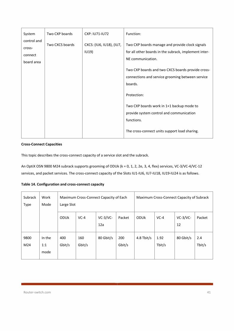
Cross-Connect Capacities
This topic describes the cross-connect capacity of a service slot and the subrack.
An OptiX OSN 9800 M24 subrack supports grooming of ODUk (k = 0, 1, 2, 2e, 3, 4, flex) services, VC-3/VC-4/VC-12
services, and packet services. The cross-connect capacity of the Slots IU1-IU6, IU7-IU18, IU19-IU24 is as follows.
Table 14. Configuration and cross-connect capacity
Subrack
Type
Work
Mode
Maximum Cross-Connect Capacity of Each
Large Slot
Maximum Cross-Connect Capacity of Subrack
ODUk VC-4 VC-3/VC-
12a
Packet ODUk VC-4 VC-3/VC-
12
Packet
9800
M24
In the
1:1
mode
400
Gbit/s
160
Gbit/s
80 Gbit/s 200
Gbit/s
4.8 Tbit/s 1.92
Tbit/s
80 Gbit/s 2.4
Tbit/s

Router-switch.com 42
In the
1:3
mode
1 Tbit/s 160
Gbit/s
80 Gbit/s 200
Gbit/s
10 Tbit/s 1.6 Tbit/s 80 Gbit/s 2 Tbit/s
a: All service slots share VC-3/VC-12 cross-connections. The maximum cross-connect capacity of a single slot or the
entire subrack is 80 Gbit/s.
Mechanical Specifications
Table 15. The mechanical specifications of the OptiX OSN 9800 M24 subrack.
Parameter 9800 M24 Specifications
Dimensions (H x W x
D)
747.2 mm x 442 mm x 295 mm
Weighta 26.49 kg
Standard working
voltage
–48 V or –60 V DC power input
Operation
Environment
Long-term running operation temperature: 0°C to +45°C
Short-term running operation temperatureb: -5°C to +50°C
Mounting option Mounted in a 19-inch or 21-inch cabinet
a: There are no boards in the board area, and no PIU or EFI boards in the power supply and interface area. In
addition, there are no fan tray assemblies in each subrack.
b: A short term refers to a maximum of 96 consecutive operating hours and the total time of short-term operating in
a year cannot exceed 15 days.
OptiX OSN 9800 P32 Chassis
Subrack Areas and Slots
Boards need to be installed in the designated slots in a subrack. The subrack runs on -48 V DC or -60 V DC.

Router-switch.com 43
The equipment includes the following areas: the power supply, system control, optical supervisory, and interface area,
fan area, fiber routing area, and service board area. PIU boards are located in the power supply, system control, optical
supervisory, and interface area. If an area has the same background color as a PIU board, the PIU board powers the
boards located in this area.
Schematic diagram of the areas and slots in the OptiX OSN 9800 P32 subrack

Router-switch.com 44
Table 16. Descriptions of the areas and slots in the OptiX OSN 9800 P32 subrack
Area Composition Slot Function
Power supply, system
control, optical
supervisory, and interface
area
6 PIU boards (PIU)
2 CTU system control
boards (TMP1CTU)
1 EFI board (TMP1EFI)
1 spectrum analyzer
boards (TMP1MON32)
PIU: IU100-IU102, IU110-
IU112
CTU: IU105, IU107
EFI: IU106
MON32: IU108-IU109
Reserved slots: IU103-
IU104
The PIU boards are in
mutual backup. Therefore,
the failure of any power
input to the equipment
does not affect the normal
operation of the
equipment.
NOTE:
The PIU boards on the left
and right sides of the EFI
board are in mutual
backup, for example, the
PIU boards in slots IU100
and IU110, the PIU boards
in slots IU101 and IU111,
and the PIU boards in slots
IU102 and IU112.
The system control boards
are configured in 1+1
backup mode. The system
control board manages
and provides a clock to all
other boards in the
equipment. It also
provides for inter-NE
communication.
The EFI board provides
maintenance and
management interfaces.

Router-switch.com 45
The MON32 board detects
the insertion loss between
the board and the
backplane and detects the
single-wavelength optical
power of optical signals in
line directions.
Fan areas 2 fan tray assemblies
(TMP1FAN)
Lower portion: IU90
Upper portion: IU91
The fan tray assemblies
are used to ventilate the
equipment.
Fiber-routing areas 4 fiber troughs N/A Fiber patch cords
connecting to boards are
routed to the left or right
side of the equipment
through the upper- and
lower-side fiber troughs.

Router-switch.com 46
Service board areas 32 service boards Lower portion: IU1–IU16
Upper portion: IU17–IU32
Service boards need to be
configured based on the
service plan and all of
them are installed in the
two service board areas.
NOTE:
To insert service boards
into a P32 subrack, certain
requirements must be
met, see Requirements for
Inserting Service Boards in
a Subrack.
Requirements for Inserting Service Boards in a Subrack
To ensure that service grooming is normal and fiber routing is convenient, service boards must be inserted into
the subrack in accordance with certain requirements.
To insert service boards into the 9800 P32 subrack, the following requirements must be met:
• The sequence of installing optical tributary boards is D->C->B->A. That is, you can insert boards in the next area
only after all slots of area D are fully inserted with boards.
• The sequence of installing optical line boards is A->B->C->D. That is, you can insert boards in the next area only
after all slots of area A are fully inserted with boards.
When the preceding board installation sequence is met:
• Because there are a large number of optical fibers on the front panels of optical tributary boards, to facilitate
future expansion using optical fibers, install the optical tributary boards from edge side to the middle in sequence.
Example: During the installation in area D, if there are two OT3232 optical tributary boards, you need to select the
area with the most convenient fiber routing according to the actual environment. Assume that the left-side area D
is selected. Preferentially use slots IU1 and IU2, and then use slots IU3 and IU4 in sequence. Assume that the
right-side area D is selected. Preferentially use slots IU16 and IU15. Other areas comply with the same rules.
• Because there are a few optical fibers on the front panels of optical line boards, install the optical line boards in
each area from left to right. Example: If there are three optical line boards, preferentially install the three optical
line boards in slots IU5-IU7 of area A from left to right in sequence. If new optical line boards need to be installed,
install them from left to right in sequence until area A is full. Other areas comply with the same rules.
NOTE:

Router-switch.com 47
Slots D and C on the left and right sides are the same. There is no requirement on the sequence of installing boards in
the two slots.
Slots for installing service boards in the OptiX OSN 9800 P32 subrack
NOTE:
The cable trough in the middle of the subrack is printed with the requirements for inserting service boards.

Router-switch.com 48
Mechanical Specifications
Table 17. The mechanical specifications of the OptiX OSN 9800 P32 subrack.
Item OptiX OSN 9800 P32 subrack
Dimensions (H x W x D) 1390 mm x 496 mm x 315 mm
Weighta 82 kg
Standard working voltage –48 V or –60 V DC power input
Operation Environment Long-term running operation temperature: 5°C to +40°C
Short-term running operation temperatureb: -5°C to
+45°C
Mounting option Mounted in an ETSI 300 A63B cabinet
a: The weight is measured when the equipment has no boards or fan tray assemblies installed.
b: A short term refers to a maximum of 96 consecutive operating hours and the total time of short-term operating in
a year cannot exceed 15 days.
OptiX OSN 9800 U16 Chassis
Subrack Areas and Slots
Boards need to be installed in the designated slots in a subrack. The subrack runs on -48 V DC or -60 V DC and is divided
into multiple areas in which boards are powered by designated PIU boards in different slots. The subrack can be
installed in an ETSI cabinet or a 19-inch cabinet.
If an area has the same background color as a PIU board, then the PIU board powers the boards located in this area.

Router-switch.com 49
Schematic diagram of the areas and slots in the OptiX OSN 9800 U16 subrack
Table 18. Descriptions of the areas and slots in the OptiX OSN 9800 U16 subrack
Area Composition Slot Function
System
control
and
cross-
connect
4 PIU boards IU68,
IU69,
IU80,
IU81
They supply power to the subrack.
The PIU boards in slots IU68 and IU80, and the PIU
boards in slots IU69 and IU81 are in mutual backup.
Therefore, the failure of any power input to the
subrack does not affect the normal operation of the
subrack.

Router-switch.com 50
board
area
1 EFI board IU79 The EFI board provides maintenance and
management interfaces.
2 CTU boards IU70,
IU78
The CTU boards manage the subrack, provide clock
for service boards, and implement inter-NE
communication.
Two CTU boards are configured for mutual backup.
7 cross-connect boards
(TNS1XCS/TNS1UXCS/TNV1SXCL)
IU71-
IU77
The cross-connect boards groom services between
service boards.
Cross-connect boards are configured in M:N backup
mode.
When a U16 subrack is used as a pure regeneration
subrack, no cross-connect board is required.
Fan
area
2 fan tray assemblies IU90,
IU91
Fan tray assemblies are used to ventilate the
equipment.
Fiber-
routing
areas
2 fiber troughs N/A Fiber patch cords connecting to boards are routed
to the left or right side of the equipment through
the upper- and lower-side fiber troughs.
Service
board
area
14 service boards IU1-
IU14
Service boards need to be configured based on the
service plan and all of them are installed in the
service board area.
Cross-Connect Capacities
This topic describes the maximum cross-connect capacity of a service slot and an OptiX OSN 9800 U16 subrack.
An OptiX OSN 9800 U16 subrack supports grooming of ODUk (k = 0, 1, 2, 2e, 3, 4, flex) services, packet services and VC-
3/VC-4/VC-12 services. Slots IU1-IU14 provide the same cross-connect capacity.
• For ODUk services, each service slot supports a maximum cross-connect capacity of 400 Gbit/s, and the subrack
provides a maximum cross-connect capacity of 5.6 Tbit/s.
• For packet services, each service slot supports a maximum cross-connect capacity of 200 Gbit/s and the
subrack provides a maximum cross-connect capacity of 2.8 Tbit/s.

Router-switch.com 51
• For VC-4 services, each service slot supports a maximum cross-connect capacity of 80 Gbit/s and the subrack
provides a maximum cross-connect capacity of 1.12 Tbit/s.
• For VC-3/VC-12 services, the subrack supports a maximum cross-connect capacity of 80 Gbit/s.
Mechanical Specifications
Table 19. The mechanical specifications of the OptiX OSN 9800 U16 subrack.
Item Mechanical Specifications
Dimensions (H x W x D) 847 mm (33.3 in.) x 442 mm (17.4 in.) x 295 mm (11.6
in.)
Weight a 40 kg (88.2 lb)
a: indicates the weight of an empty subrack. An empty subrack is equipped with no boards, fan tray assembly, or air
filter.
OptiX OSN 9800 U32 Chassis
Subrack Areas and Slots
Boards need to be installed in the designated slots in the subrack. The subrack runs on -48 V DC or -60 V DC and is
divided into different areas in which boards are powered by designated PIU boards in different slots.
The subrack includes the following areas: indicator area, power and interface area, fan area, fiber-routing area, service
board area, and system control and cross-connect board area. PIU boards are located in the power and interface area.
If an area has the same background color as a PIU board, then the PIU board powers the boards located in this area.

Router-switch.com 52
Schematic diagram of the areas and slots in the 9800 U32 subrack
Table 20. Descriptions of the areas and slots in the OptiX OSN 9800 U32 subrack
Area Composition Slot Function
Power and
interface
area
1 EFI board and 10
PIU boards
PIU: IU100-IU104,
IU106-IU110
EFI: IU105
The PIU boards are in mutual backup. Therefore, the
failure of any power input to the equipment does not
affect the normal operation of the equipment.
NOTE:
The PIU boards on the left and right sides of the EFI
board are in mutual backup, for example, the PIU

Router-switch.com 53
boards in slots IU100 and IU106, the PIU boards in slots
IU101 and IU107, and so on.
The EFI board provides maintenance and management
interfaces.
Fan areas 4 fan tray
assemblies
Lower portion: IU90,
IU91
Upper portion: IU92,
IU93
The fan tray assemblies are used to ventilate the
equipment.
Fiber-
routing
areas
2 fiber troughs N/A Fiber patch cords connecting to boards are routed to the
left or right side of the subrack through the upper- and
lower-side fiber troughs.
Service
board areas
32 service boards Lower portion: IU1-
IU16
Upper portion: IU17-
IU32
Service boards need to be configured based on the
service plan and all of them are installed in the two
service board areas.
NOTE:
Service boards installed in slots IU1-IU16 have their
ejector levers on the right sides of the board front
panels. Service boards installed in remaining slots in the
two areas have their ejector levers on the left sides of
the board front panels.
System
control and
cross-
connect
board area
2 CTU system
control boards and
7 XCS cross-
connect boards
XCS: IU71-IU77
CTU: IU70, IU78
Cross-connect boards are configured in M:N backup
mode. The cross-connect boards provide cross-
connections for service boards.
The system control boards are configured in 1+1 backup
mode. The active system control board manages and
provides a clock to all other boards in the equipment. It
also provides for inter-NE communication.

Router-switch.com 54
Cross-Connect Capacities
This topic describes the cross-connect capacity of a service slot and an OptiX OSN 9800 U32 subrack.
An OptiX OSN 9800 U32 subrack supports grooming of ODUk (k = 0, 1, 2, 2e, 3, 4, flex) services, packet services and VC-
3/VC-4/VC-12 services. Slots IU1-IU32 provide the same cross-connect capacity.
• For ODUk services, each service slot supports a maximum cross-connect capacity of 400 Gbit/s, and the subrack
provides a maximum cross-connect capacity of 12.8 Tbit/s.
• For packet services, each service slot supports a maximum cross-connect capacity of 200 Gbit/s and the subrack
provides a maximum cross-connect capacity of 6.4 Tbit/s.
• For VC-4 services, each service slot supports a maximum cross-connect capacity of 80 Gbit/s and the subrack
provides a maximum cross-connect capacity of 2.56 Tbit/s.
• For VC-3/VC-12 services, the subrack supports a maximum cross-connect capacity of 80 Gbit/s.
Mechanical Specifications
Table 21. The mechanical specifications of the OptiX OSN 9800 U32 subrack
Item Specification
Dimensions (H x W x D) 1900 mm x 498 mm x 295 mm
Weighta 68 kg
a: The weight is measured when the subrack has no boards or fan tray assemblies installed.
OptiX OSN 9800 U64 Chassis
Subrack Areas and Slots
The OptiX OSN 9800 U64 equipment has integrated the OptiX OSN 9800 U64 subrack in a cabinet and provides board
slots on both the front and rear sides. Boards need to be installed in the designated slots. The equipment runs on -48 V
DC or -60 V DC and is divided into different areas in which boards are powered by designated PIU boards in different
slots.
The equipment includes the following areas: indicator area, power and interface area, fan area, fiber-routing area,
service board area, and system control and cross-connect board area. PIU boards are located in the power and
When a U32 subrack is used as a pure regeneration
subrack, no cross-connect board is required.

Router-switch.com 55
interface area. If an area has the same background color as a PIU board, then the PIU board powers the boards located
in this area.
Schematic diagram of the areas and slots in the OptiX OSN 9800 U64 subrack
Table 22. Descriptions of the areas and slots in the OptiX OSN 9800 U64 subrack
Area Composition Slot Function
Power
and
Front 1 EFI board and 10 PIU
boards
PIU: IU100-IU104, IU106-
IU110
EFI: IU105
The PIU boards on the front and rear
sides are in mutual backup.
Therefore, the failure of any power
input to the equipment does not

Router-switch.com 56
interface
area
Rear 10 PIU boards PIU: IU111-IU115, IU117-
IU121
IU116: reserved
affect the normal operation of the
equipment.
NOTE:
The PIU boards installed back-to-back
are in mutual backup, for example,
the PIU boards in slots IU100 and
IU121, the PIU boards in slots IU101
and IU120, and so on.
The EFI board provides maintenance
and management interfaces.
Fan
areas
Front 4 fan tray assemblies Lower portion: IU90, IU91
Upper portion: IU92, IU93
The fan tray assemblies are used to
ventilate the equipment.
Rear 4 fan tray assemblies Lower portion: IU94, IU95
Upper portion: IU96, IU97
Fiber-
routing
areas
Front 2 fiber troughs N/A Fiber patch cords connecting to
boards are routed to the left or right
side of the equipment through the
upper- and lower-side fiber troughs.
Rear 2 fiber troughs
Service
board
areas
Front 32 service boards Lower portion: IU1-IU16
Upper portion: IU17-IU32
Service boards need to be configured
based on the service plan and all of
them are installed in the two service
board areas.
NOTE:
Service boards installed in slots IU1-
IU16 and IU33-IU48 have their
ejector levers on the right sides of
the board front panels. Service
boards installed in remaining slots in
Rear 32 service boards Lower portion: IU33-IU48
Upper portion: IU49-IU64

Router-switch.com 57
the two areas have their ejector
levers on the left sides of the board
front panels.
System
control
and
cross-
connect
board
area
Front 2 CTU system control
boards and 7 XCS cross-
connect boards
XCS: IU71-IU77
CTU: IU70, IU78
Cross-connect boards are configured
in M:N backup mode to implement
cross-connections for services boards
on the front and rear sides.
The system control boards are
configured in 1+1 backup mode. The
active system control board manages
and provides a clock to all other
boards in the equipment. It also
provides for inter-NE communication.
When a U64 subrack is used as a pure
regeneration subrack, no cross-
connect board is required.
Rear 7 XCS cross-connect
boards
XCS: IU79-IU85
Cross-Connect Capacities
This topic describes the cross-connect capacity of a service slot and an OptiX OSN 9800 U64 subrack.
An OptiX OSN 9800 U64 subrack supports grooming of ODUk (k = 0, 1, 2, 2e, 3, 4, flex) services, packet services and VC-
3/VC-4/VC-12 services. Slots IU1-IU64 provide the same cross-connect capacity.
• For ODUk services, each service slot supports a maximum cross-connect capacity of 400 Gbit/s, and the subrack
provides a maximum cross-connect capacity of 25.6 Tbit/s.
• For packet services, each service slot supports a maximum cross-connect capacity of 200 Gbit/s and the subrack
provides a maximum cross-connect capacity of 12.8 Tbit/s.
• For VC-4 services, each service slot supports a maximum cross-connect capacity of 80 Gbit/s, and the subrack
provides a maximum cross-connect capacity of 5.12 Tbit/s.
• For VC-3/VC-12 services, the subrack supports a maximum cross-connect capacity of 80 Gbit/s.

Router-switch.com 58
Mechanical Specifications
Table 23. The specifications of the OptiX OSN 9800 U64 equipment
Item Specification
Dimensions (H x W x D) 2200 mm x 600 mm x 600 mm
Weighta 180 kg
a: The weight is measured when the equipment has no boards or fan tray assemblies installed.
Board Description
Table 24. Appearance and Dimensions of Universal Platform Subrack Boards
Board Appearance Board Name Number of
Slots
Required by
the Board
Height (mm) Width (mm) Depth (mm)
TN52ND2 1 264.6 25.4 220.0
TN11RAU1 2 264.6 50.8 220.0

Router-switch.com 59
TN11M40 3 264.6 76.2 220.0
Table 25. Appearance and Dimensions of M24 Boards
Board Appearance Board
Name
Number of
Slots
Required
by the
Board
Height
(mm)
Width
(mm)
Depth
(mm)
TNG1A212 1 237.1 30.5 220.0

Router-switch.com 60
TNG1CXP 1 489.5 30.5 220.0
TNG1EFI 1 57.1 121.9 247.5
TNG2PIU 1 57.1 61.0 241.2

Router-switch.com 61
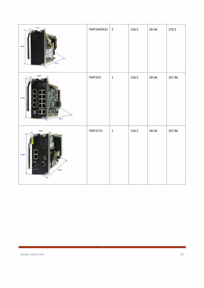
Table 26. Appearance and Dimensions of P32 Boards
Board Appearance Board Name Number
of Slots
Required
by the
Board
Height
(mm)
Width
(mm)
Depth
(mm)
TMP1OT3232 1 477.25 29.98 276.5
TMP1ON32 1 477.25 29.98 276.5
Router-switch.com 62
TMP1MON32 2 136.5 60.46 276.5
TMP1EFI 1 136.5 60.46 267.86
TMP1CTU 1 136.5 60.46 267.86

Router-switch.com 63
Table 27. Appearance and Dimensions of U64/U32/U16 Boards
Board Appearance Board Name Number of
Slots
Required by
the Board
Height
(mm/in.)
Width
(mm/in.)
Depth
(mm/in.)
TNV1N302 1 477.3 30.5 220.0
TNU1N601 2 477.3 61.0 220.0
TNV1EFI 1 102.8 56.9 220.0

Router-switch.com 64
TNV1PIU 1 102.8 44.4 220.0
TNS1CTU 1 182.9 29.98 267.75
TNS1EFI 1 182.9 35 267.75
TNS1PIU 1 136.5 22.36 279.7

Router-switch.com 65
TNS1XCS 1 182.9 35 265.9
Basic Ordering Information
Table 28. Ordering information of Huawei OptiX OSN 9800.
Model Description
Huawei Optix OSN 9800 U16 Huawei OSN 9800 U16 subrack, a next-generation large-capacity OTN product
that integrates ASON, OTN, and packet functions for 100G optical networks,
applicable to various networks, including super-backbone, backbone, and metro
networks
Huawei Optix OSN 9800 U32 Huawei OSN 9800 U32 subrack, a next-generation large-capacity OTN product
that integrates ASON, OTN, and packet functions for 100G optical networks,
applicable to various networks, including super-backbone, backbone, and metro
networks
Huawei Optix OSN 9800 U64 Huawei OSN 9800 U64 subrack, a next-generation large-capacity OTN product
that integrates ASON, OTN, and packet functions for 100G optical networks,
applicable to various networks, including super-backbone, backbone, and metro
networks
Huawei Optix OSN 9800 Ups Huawei OSN 9800 universal platform subrack mainly works with the OSN 9800
U64/U32/U16/M24, which is applied at the electrical layer in WDM and OTN
system, enables end-to-end OTN/WDM backbone transport solutions and
implements multi-service, large-capacity, and fully transport transmission

Router-switch.com 66
Huawei Optix OSN 9800 M24 Huawei OSN 9800 M24, a next-generation ultra-large capacity, high integration,
and optoelectronic OTN/WDM product developed based on new software and
hardware platforms, applicable to backbone and metro networks.
Huawei Optix OSN 9800 P32 Huawei OSN 9800 P32 subrack is an ultra-large capacity all-optical cross-connect
product, used at the backbone core layer and metro aggregation layer and
works with the OSN 9800/1800 to build a complete E2E WDM/OTN backbone
transmission solution, achieving transparent and ultra-large capacity
transmission
Where to Buy
Want to buy this series of products? please contact:
● Tel: +1-626-239-8066 (USA)/ +852-3050-1066 / +852-3174-6166
● Fax: +852-3050-1066 (Hong Kong)
● Email: [email protected] (Sales Inquiries)
Or visit: Huawei OptiX OSN 9800 Products
Hot Products of Huawei Transmission Network:
Huawei OptiX OSN 1800 Huawei OptiX OSN 500
Huawei OptiX OSN 550 Huawei OptiX OSN 3500
Huawei OptiX OSN 3800 Huawei OptiX OSN 7500
Huawei OptiX OSN 7500 II Huawei OptiX OSN 8800
Huawei OptiX OSN 6800 Huawei OptiX OSN 580

Router-switch.com 67
About us
Router-switch.com, founded in 2002, is one of the biggest Global Network Hardware Supplier. We are a leading provider
of network products with 14,500+ customers in over 200 countries. We provide original new and used network
equipments ( Cisco, Huawei, HPE, Dell, Hikvision, Juniper, Fortinet, etc.), including Routers, Switches, Servers, Storage,
Telepresence and Videoconferencing, IP Phones, Firewalls, Wireless APs & Controllers, EHWIC/HWIC/VWIC Cards, SFPs,
Memory & Flash, Hard Disk, Cables, and all kinds of network solutions related products.
Sources
https://support.huawei.com/enterprise/en/transmission-network/optix-osn-9800-u16-pid-21110042