Embed Size (px)
Citation preview

R&D ERL
HTS Solenoid
Ramesh Gupta, Joe Muratore, Steve Plate and Bill Sampson
February 17 18 2010February 17-18, 2010
February 17-18, 2010Ramesh Gupta – HTS Solenoid

R&D ERLOverview
• Overall design : HTS solenoid inside the cryostat over the bellows
• Magnetic design
• Mechanical designMechanical design
• Construction
SC cavity
• Measurements
b k• Future plans & Summary
Inner shield Thermal shield Outer shield
main coil
buck coil
February 17-18, 2010Ramesh Gupta – HTS Solenoid2
Inner shield Thermal shield Outer shield

R&D ERLBenefits of HTS Solenoid inside the cryostat
• Solenoid inside the cryostat and very close to cavity provides early focusing which reduces beam emittance. Originally, HTS solenoid was proposed as it can be conveniently placed inside the cryostat in a cold to warm transition region - say ~20 K. NbTi won’t work at 20 K and Cu magnet will be too big and create too much heat.
• The major advantage HTS over NbTi continues to be that it allows tests with LN2 as solenoid is designed to reach the nominal field at 77 K LN not only makes tests ansolenoid is designed to reach the nominal field at 77 K. LN2 not only makes tests an order of magnitude cheaper than testing in LHe at ~4 K (for NbTi), but also practical. Note: HTS cost is a fraction of overall solenoid cost (design, construction & testing).
• Conduction cooling and current leads become simple and attractive as temperature gradient is no longer an issue with a large thermal margin in case of HTS.
• Because the solenoid reaches the design field at ~80 K while cavity is still normal, one can go through the demagnetization cycle while cavity is still cooling down and has not yet reached the superconducting state.
February 17-18, 2010Ramesh Gupta – HTS Solenoid

R&D ERLMagnetic Design
• There are two coils – main and bucking
• They are independently powered to bt i b t ll ti f fi ld t idtic
shi
eld
obtain best cancellation of field outside
• Inner magnetic shield has been placed in between cavity and solenoid to O
uter
mag
net
yminimize field on the cavity
• Yoke is not saturated
SC cavity
Inner magnetic
(specially on the cavity side).
• Field inside the solenoid is
shield
main coil
bucking coil yoke
primarily determined by yoke.main coil
February 17-18, 2010Ramesh Gupta – HTS Solenoid

R&D ERLMajor Parameters of the HTS Solenoid
Parameters ValueCoil Inner Diameter 175 mmCoil Outer Diameter 187 mmNo. of Turns in Main Coil 180No. of Turns in Main Coil 180No. of Turns in Bucking Coil 30 (2X15)Coil Length (Main Coil) ~56 mmCoil Length (Bucking Coil) ~9 mmConductor (First Generation HTS) BSCCO2223 TapeConductor (First Generation HTS) BSCCO2223 TapeInsulation KaptonTotal Conductor Used 118 meterNominal Integral Focusing 1 T2. mm (axial)Nominal Current in Main Coil 54.2 ANominal Current in Bucking Coil -17 AMax. Field on Conductor, Parallel/Perpendicular 0.25 T/0.065 T Stored Energy ~25 JoulesInductance (main coil) 0.13 HenryYoke Inner Radius 55 mmYoke Outer radius 114 mmYoke Length ( + Bucking) 147 mm
February 17-18, 2010Ramesh Gupta – HTS Solenoid5
Yoke Length ( Bucking) 147 mm

R&D ERLDesired Focusing from the Solenoid
dzBz2 1 T2 . mm
Basic Requirement : along the z- axisVariation of B z2
Field in T2
Larger coil : 15 X 12 turnsSmaller coil : 15 X 2 turnsNominal current : 33.6 Amp
February 17-18, 2010Ramesh Gupta – HTS Solenoid

R&D ERLBucking Coil to Reduce Field inside the cavity
Fi ld i id
Field (G) Inside Cavity Region
Field inside cavity with bucking coil on
Bucking coil significantly reduces the field inside the
Field inside cavity with bucking coil turned off
field inside the cavity region
February 17-18, 2010Ramesh Gupta – HTS Solenoid

R&D ERLBucking Coil and Inner Magnetic Shield to Reduce Field on the Superconducting Cavity
The goal is to avoid trapped field problem on cavity
Bucking coil OFF
Bucking coil ON
• Inner magnetic shield and bucking coils makes field on the
Bucking coil OFF
g gsuperconducting cavity very small in the operating range of the solenoid• Field is about 10 mG in the significant part of the critical region • These critical results are being verified experimentally
February 17-18, 2010Ramesh Gupta – HTS Solenoid
These critical results are being verified experimentally

R&D ERLMechanical Design and Assembly
Main Components of pthe HTS Solenoid
February 17-18, 2010Ramesh Gupta – HTS Solenoid 9

R&D ERLShip to and Return from Configurations J-Lab
• Ship partial assembly to J-Lab• J-Lab builds hermetic string
Shi b k l ith th t• Ships back along with other components
as shipped(bucking coil and tooling to securetooling to secure coils not shown)
Return configuration from J-Lab
February 17-18, 2010Ramesh Gupta – HTS Solenoid 10
o J ab

R&D ERLFlexible HTS Leads & Heat Stationing
• We have developed flexible HTS leads for this application
• HTS lead with Kapton over top• HTS lead with Kapton over top• Laminated G-10 sheet, .015 thick each• Motion during cooldown
– radial = 011 inches cooldown– radial = .011 inches cooldown– axial = +/-0.043 max
• Heat shield at 77K• Heat shield at 77K• Copper terminals thermally connected
to boss, but isolated electrically
February 17-18, 2010Ramesh Gupta – HTS Solenoid 11

R&D ERLCooling
• Coils are conduction cooled (avoids separate vacuum structure)• Outside Aluminum coolars are cooled by helium• Heat transfer to interference-fit yoke and then to HTS coil• Attempt is made to have good conduction. However, we have extremely large temperature margin (well over 50 K) because of HTS coils
Helium cooldown
time to 4.2K: ~16 hours
February 17-18, 2010Ramesh Gupta – HTS Solenoid 12

R&D ERLConstruction of HTS Coils
HTS tape was delivered with kapton insulation
d itpre-wrapped on it
Main coil was layer wound (15 l h ith 12 t )(15 layers each with 12 turns) and the bucking coil was wound in double-pancake style
February 17-18, 2010Ramesh Gupta – HTS Solenoid

R&D ERLConstruction of HTS Solenoid
Aluminum collar & yoke over the coil Note: Leads
and Cooling
February 17-18, 2010Ramesh Gupta – HTS Solenoid14

R&D ERLConstruction of Low Cost Test Set-up
• A low cost test set up is possible because HTS solenoid reaches the• A low cost test set-up is possible because HTS solenoid reaches the desired field at 77K (LN2).
• The cost was further reduced by imaginative use of surplus equipment from farms, etc.
• Such low cost test would not have been possible for conventional LTS solenoid operating at 4 K with the cost of new test dewar.
February 17-18, 2010Ramesh Gupta – HTS Solenoid15
p g

R&D ERL
MeasurementsMeasurements
1. Assure that the HTS solenoid reaches design current with margin
2. Assure that the fringe fields on cavity are within acceptable limitg y p
3. Assure that solenoid provides desired focusing (field on the axis)
February 17-18, 2010Ramesh Gupta – HTS Solenoid16

R&D ERLPerformance of HTS Coils in LN2
0.80.91.0
V/cm
)
Industry
0 40.50.60.7
radi
ent (
V Main CoilBucking Coil
ydefinition of Icis for 1 V/cm
0.10.20.30.4
Volta
ge G
r
We use a safer 0.1 V/cm
0.00.1
0 5 10 15 20 25 30 35 40 45 50 55 60 65 70 75 80 85 90
Current (Amp)
V
( p)
• Both coils exceed design current (~54 A & ~17 A) at 77 K itself
• These tests were performed with no iron yoke over the coils
February 17-18, 2010Ramesh Gupta – HTS Solenoid17

R&D ERLHTS Solenoid Has More Margin with Iron Yoke
Field parallel(0.15 T max)
Field perpendicular(0 15 T max)
Field parallel(0.15 T max)
Field perpendicular(0 15 T max)
Components of the fields in the absence of yoke ironWire specifications for 77 K, self fieldScaling ratio determines performance at any temperature & field combination In HTS it depends on the direction
(0.15 T max)(0.15 T max)
Components of the fields in the presence of yoke iron A significantly reduction in the perpendicular component Thus actual solenoid (with iron) will have extra margin
February 17-18, 2010Ramesh Gupta – HTS Solenoid18

R&D ERLPreparation of the Fringe Field Measurements
The goal is to measure (a) field on the axis of solenoid and (b) fringe field at the locationThe goal is to measure (a) field on the axis of solenoid and (b) fringe field at the location of cavity in the operating range with bucking coil and inner magnetic shield in place. We have made initial measurements and are getting ready for more detailed measurements. There is a generally good agreement between calculations and Measurements.
Warm Finger
LN2 Test cryostat with shield in place
Vertical transporter and computer control cart
Transverse and axial fluxgates
February 17-18, 2010Ramesh Gupta – HTS Solenoid19
with shield in place computer control cart axial fluxgates

R&D ERLSummary• HTS solenoid offers a unique solution
– It allows solenoid very close to cavityIt allows solenoid very close to cavity
– It allows a conduction-cooled design with large margin
It allows critical tests to be performed at liquid nitrogen itself which not– It allows critical tests to be performed at liquid nitrogen itself which not
only significantly reduces the cost of the overall system but make some
of them possible as wellof them possible as well.
• Measurements show that HTS solenoid reaches the design field at 77 K
itself (would have a large margin at operating temperature <20 K)itself (would have a large margin at operating temperature <20 K)
• Fringe field measurements are being carried out
February 17-18, 2010Ramesh Gupta – HTS Solenoid20

R&D ERL
Additional Slides
February 17-18, 2010Ramesh Gupta – HTS Solenoid21

R&D ERLChallenges with HTS Solenoid inside the Cryostat
and how we deal with them (1)
HTS is considered to be a new technologyWe do a number of performance tests at several stages
W h l i d i t i d fWe have a very large margin - design current is over an order of
magnitude below the critical current
BNL has successfully built and tested many HTS coils & magnets
HTS coils built at BNL
February 17-18, 2010Ramesh Gupta – HTS Solenoid22
HTS coils built at BNL

R&D ERLHTS Magnets Technology at BNL
Mirror Iron
Return Yoke Iron Pole
Various types of HTSHTS Coils in Structure
Various types of HTS magnets successfully built and tested at BNL over the decade
February 17-18, 2010Ramesh Gupta – HTS Solenoid23

R&D ERLChallenges with HTS Solenoid inside the Cryostat
and how we deal with them (2)
Solenoid close to SC cavity may create significant fringe field
We have a tunable bucking coil and inner magnetic shield to
make field within ~10 mG to avoid trapped field problem on cavity
We have an experimental program to verify that the fields are low
February 17-18, 2010Ramesh Gupta – HTS Solenoid24

R&D ERLField Measurements
Fluxgate magnetometers measurement setup
Warm finger for hall probe measurements for field on the axis
Transverse (left) and axial (right) fluxgate probes in holders
February 17-18, 2010Ramesh Gupta – HTS Solenoid25
p

R&D ERLStatus of the Fringe Field Measurements
• Solenoid reaches the design performance at 77 K itself (that means a large temperature margin), now with yoke over the coil (earlier it was measured without iron)measured without iron)
• Initial measurements have been performed for field on the axis and one position off axis with hall probe in and outside solenoidposition off axis with hall probe in and outside solenoid
• Initial high precision, low field fringe field measurements have been performed with fluxgate probes in the region where cavity will be placedperformed with fluxgate probes in the region where cavity will be placed
• There is a general agreements between calculations and measurements.
February 17-18, 2010Ramesh Gupta – HTS Solenoid26

R&D ERLFringe Field with Bucking Coil
3 MAIN SOLENOID AT 54.2 A
1
2
T)
-1
0
Fiel
d (u
T
4
-3
-2
Frin
ge
6
-5
-4Transverse FieldAxial Field
-6-10 0 10 20 30 40 50 60
Bucking Coil Current (A)
February 17-18, 2010Ramesh Gupta – HTS Solenoid

R&D ERLAxial Field
Main Solenoid Field at 54.2 A0 018
along the z- axisVariation of B z2B z2
0.012
0.014
0.016
0.018
2 ) n T2
0 004
0.006
0.008
0.010
Bz*
Bz
( T2
Fiel
d in
0.000
0.002
0.004
135 140 145 150 155 160
P iti (i h )
On-axis
Position (inches)
Axial Position (mm)Measurements without bucking coil
Calculations with bucking coil
February 17-18, 2010Ramesh Gupta – HTS Solenoid
Calculations with bucking coil

R&D ERLFringe field with the shielding from Superconducting Cavity(Nominal current in Main and Bucking Coils)
10 mG = 1 micro T
February 17-18, 2010Ramesh Gupta – HTS Solenoid
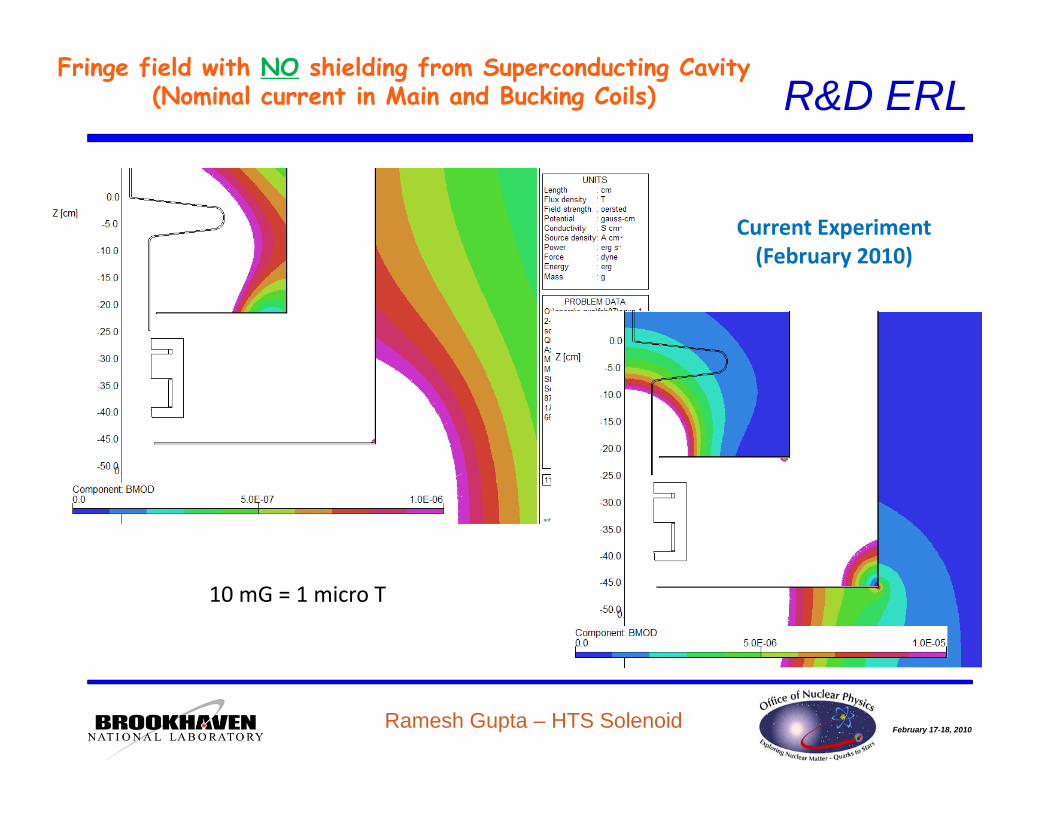
R&D ERLFringe field with NO shielding from Superconducting Cavity
(Nominal current in Main and Bucking Coils)
Current Experiment(February 2010)(February 2010)
10 mG = 1 micro T
February 17-18, 2010Ramesh Gupta – HTS Solenoid

R&D ERLFringe field components with NO shielding from Superconducting Cavity
(Nominal current in Main and Bucking Coils)
Current Experiment(February 2010)(February 2010)
Radial ad aComponent
Axial C t
10 mG = 1 micro T
Component
February 17-18, 2010Ramesh Gupta – HTS Solenoid

R&D ERLFringe field with NO shielding from Superconducting Cavity
NOTE: Extended Shielding(Nominal current in Main and Bucking Coils)
Proposal(if needed)
10 mG = 1 micro T
February 17-18, 2010Ramesh Gupta – HTS Solenoid


![Design Construction and Test Results of a HTS Solenoid for ... · design, construction and test results of this HTS solenoid. INTRODUCTION The HTS solenoid in the proposed ERL [1]](https://img.dokumen.tips/doc/110x75/5e98eeb3d48df049c9709544/design-construction-and-test-results-of-a-hts-solenoid-for-design-construction.jpg)


