Embed Size (px)
Citation preview
HT Wind Engineering:Early Considerations
Forrest J. Masters, Ph.D., P.E.Associate Dean for Research and Facilities, Herbert Wertheim College of Engineering
Associate Professor of Civil and Coastal Eng., School of Sustainable Infrastructure & Env.University of Florida, USA

EARTHQUAKE ENGINEERS
HAVE THE SHAKE TABLE
COASTAL ENGINEERS
HAVE THE WAVE TANK
BLAST & IMPACT ENGINEERS
HAVE THE SHOCK TUBE
WIND ENGINEERS
HAVE…
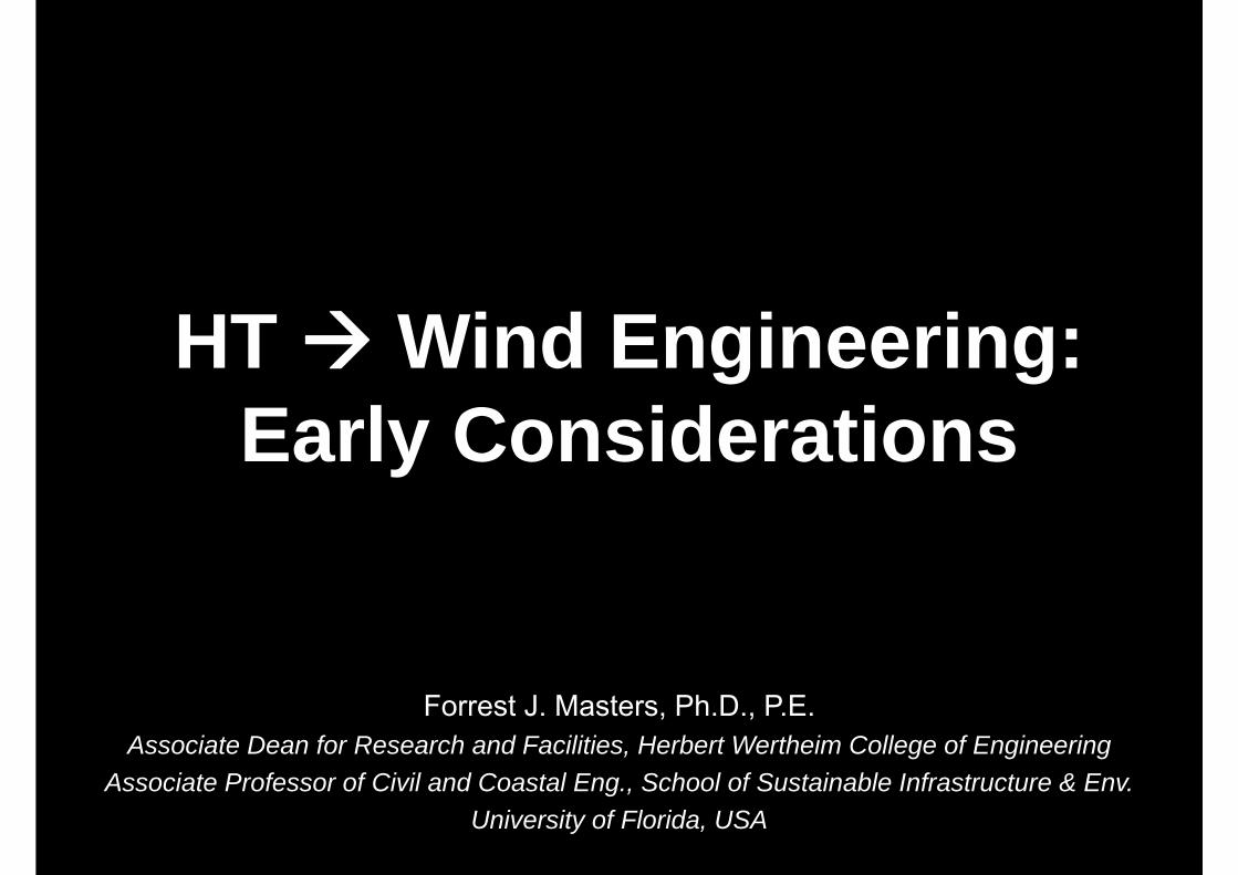
… two types of full-scale simulators
• Wind Field– FIU Wall of Wind– IBHS Research Center– UF Hurricane Simulator
• Dynamic Pressure– BRERWULF– UWO Three Little Pigs– UF HAPLA, SPLA & MAWLS
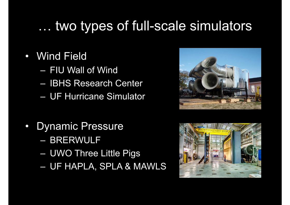
• Wind Field– FIU Wall of Wind– IBHS Research Center– UF Hurricane Simulator
• Dynamic Pressure– BRERWULF– UWO Three Little Pigs– UF HAPLA, SPLA & MAWLS
… two types of full-scale simulators
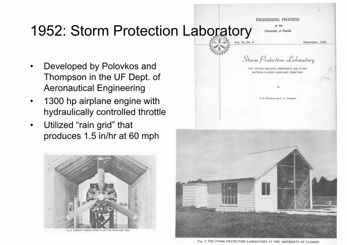
1952: Storm Protection Laboratory
• Developed by Polovkos and Thompson in the UF Dept. of Aeronautical Engineering
• 1300 hp airplane engine with hydraulically controlled throttle
• Utilized “rain grid” that produces 1.5 in/hr at 60 mph
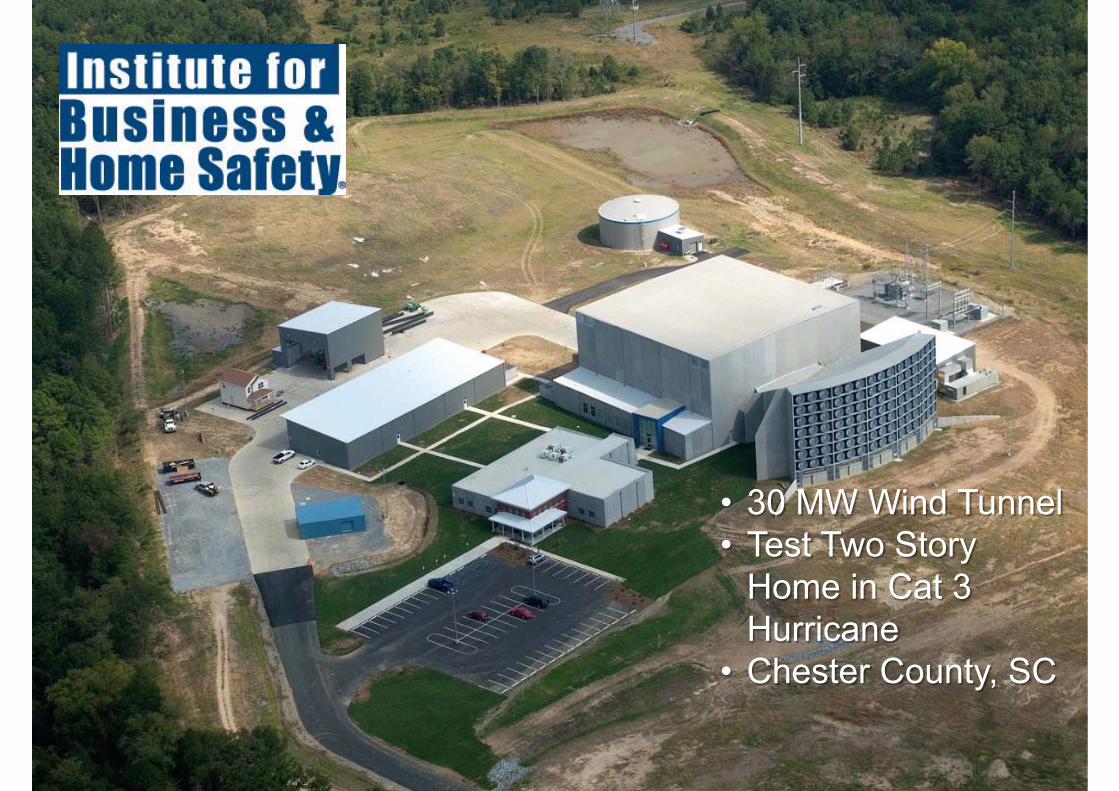
• 30 MW Wind Tunnel• Test Two Story
Home in Cat 3 Hurricane
• Chester County, SC

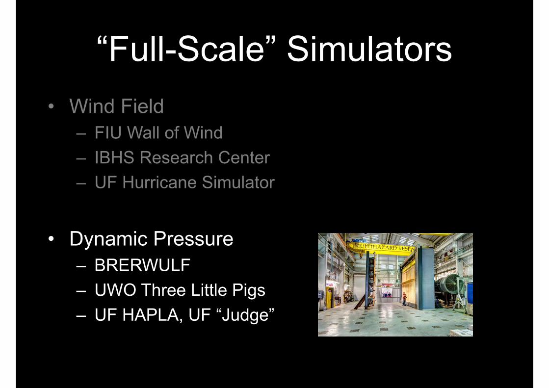
“Full-Scale” Simulators• Wind Field
– FIU Wall of Wind– IBHS Research Center– UF Hurricane Simulator
• Dynamic Pressure– BRERWULF– UWO Three Little Pigs– UF HAPLA, UF “Judge”

Command
Achieved
Strong advection+ flow separation

Pressure Loading Actuators
BRE Real-Time Wind Uniform Load FollowerPressure Loading Actuator
Test specimen
Valve
PLAPhoto Source: (Prevatt, 1998)
Kopp et al., 2010)
Cook et al., 1988
Interior
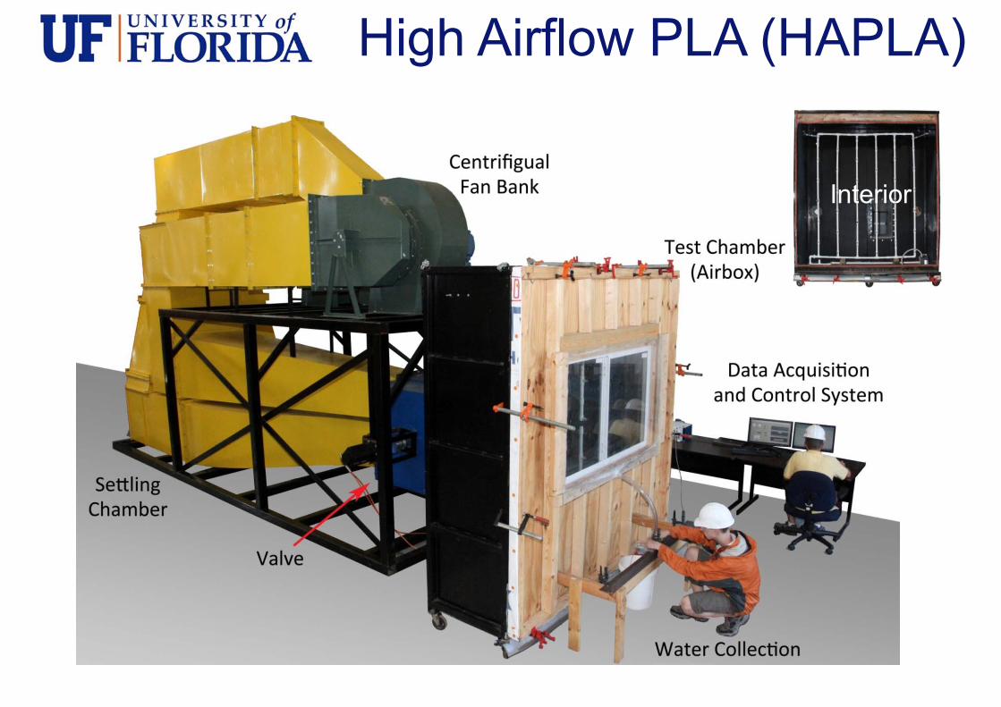
High Airflow PLA (HAPLA)

Spatiotemporal PLA (SPLA)

Multi‐Axis Wind Load Simulator (MAWLS)
14
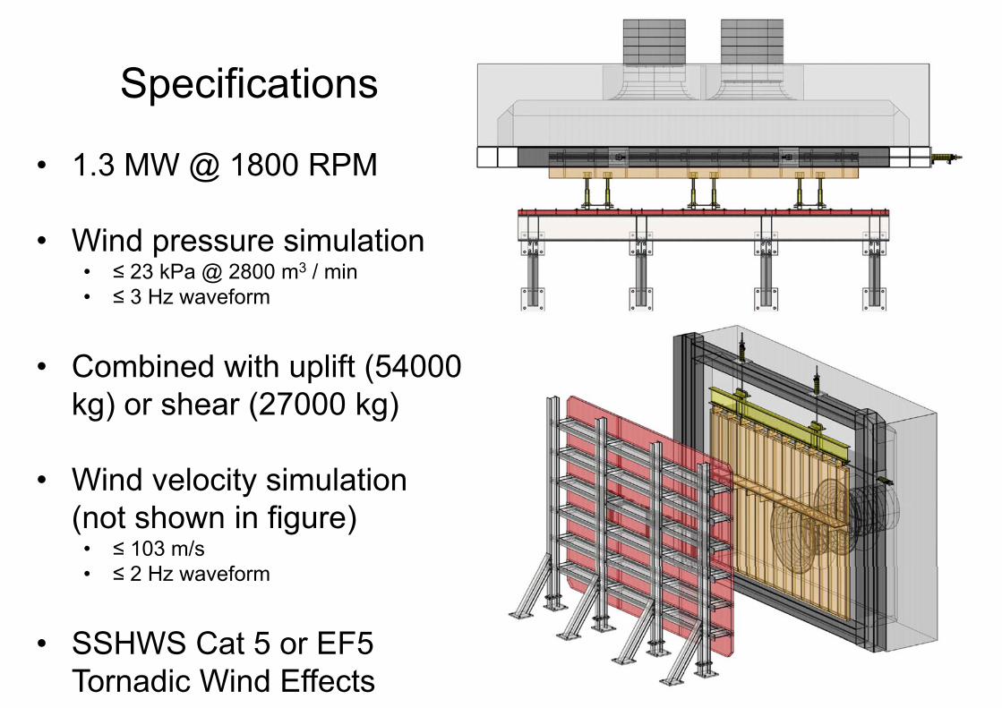
Specifications
• 1.3 MW @ 1800 RPM
• Wind pressure simulation• ≤ 23 kPa @ 2800 m3 / min• ≤ 3 Hz waveform
• Combined with uplift (54000 kg) or shear (27000 kg)
• Wind velocity simulation (not shown in figure)
• ≤ 103 m/s• ≤ 2 Hz waveform
• SSHWS Cat 5 or EF5 Tornadic Wind Effects
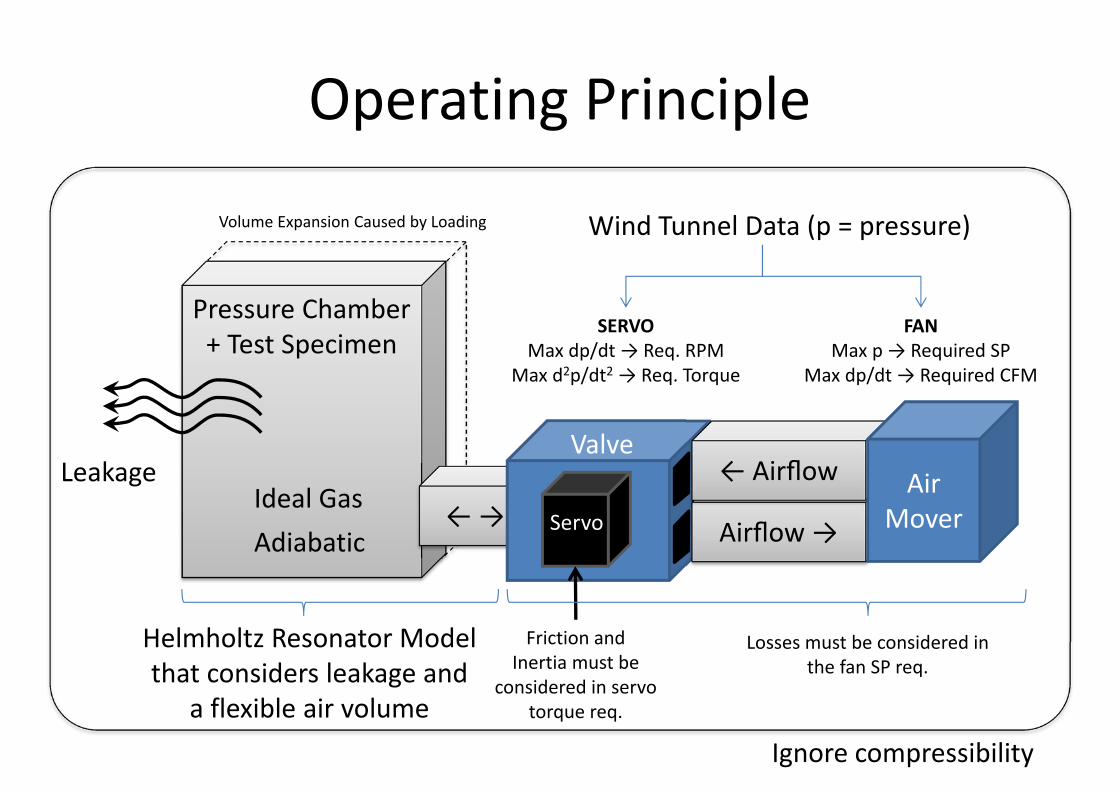
Pressure Chamber + Test Specimen
← →
Operating Principle
Airflow →
← Airflow AirMover
Valve
Ideal GasLeakage
Helmholtz Resonator Modelthat considers leakage and
a flexible air volumeIgnore compressibility
Wind Tunnel Data (p = pressure)Volume Expansion Caused by Loading
Friction andInertia must be
considered in servo torque req.
Servo
FANMax p → Required SP
Max dp/dt→ Required CFM
SERVOMax dp/dt→ Req. RPM
Max d2p/dt2 → Req. Torque
Losses must be considered in the fan SP req.
Adiabatic
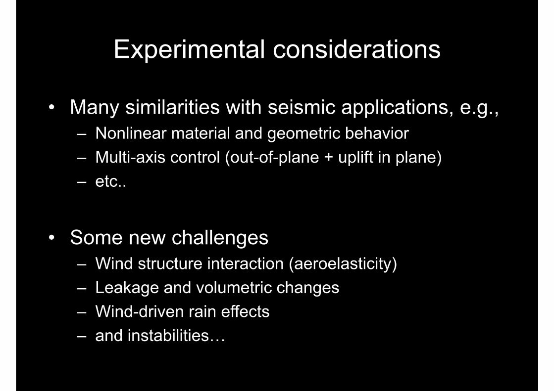
Experimental considerations
• Many similarities with seismic applications, e.g.,– Nonlinear material and geometric behavior– Multi-axis control (out-of-plane + uplift in plane)– etc..
• Some new challenges– Wind structure interaction (aeroelasticity)– Leakage and volumetric changes– Wind-driven rain effects– and instabilities…

Instabilities, e.g., Helmholtz Resonance
Air Slug
tpAxV
Apxxk
AxAl eair
eair 0
20
22
The differential equation for the motion of a slug of air moving in and out of the volume:
slugair oflength effectiveelopening of AreaA
InertialTerm
LossTerm
“Stiffness”Term
volumeofout andin moves slugair distancex
Forcing
nRTpV Ideal Gas Law
Air moves in, n↑p↑ Air moves out, n↓p↓
constantint
int pAdiabatic
• But why stop at full-scale?
• The principle tool of the wind engineering community is the boundary layer wind tunnel
• We can conduct aeroelastic tests using flexible models… introduce controls to modulate stiffness and damping
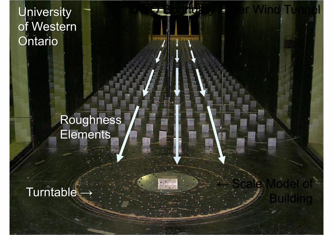
UWO Boundary Layer Wind Tunnel
← Scale Model of BuildingTurntable →
RoughnessElements
Universityof Western Ontario
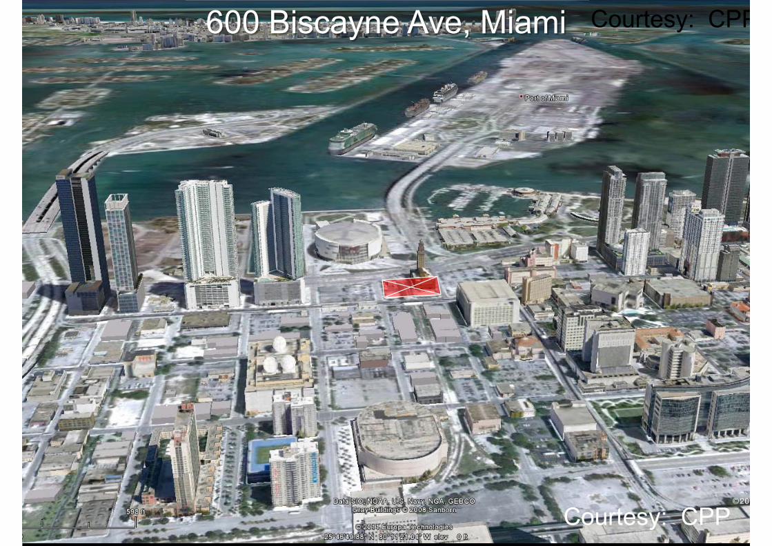
600 Biscayne Ave, Miami Courtesy: CPP
Courtesy: CPP

600 Biscayne Ave, Miami
Courtesy: CPP

Aeroelastic Models
• Tall buildings and slender vertical structures
• Long span bridges• Flexible roofs• Small structures, building
appendages and structural members
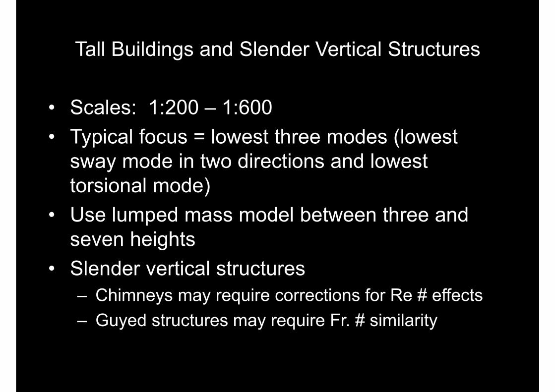
Tall Buildings and Slender Vertical Structures
• Scales: 1:200 – 1:600• Typical focus = lowest three modes (lowest
sway mode in two directions and lowest torsional mode)
• Use lumped mass model between three and seven heights
• Slender vertical structures– Chimneys may require corrections for Re # effects– Guyed structures may require Fr. # similarity


Long Span Bridges
• Establish the basic aerodynamic stability
• Types of testing– Full aeroelastic model with or
without topography)– Sectional model. Scales = 1:10 to
1:100

Akashi Kaikyō Bridge
http://en.wikipedia.org/wiki/File:Akashi_Bridge.JPG

Akashi Kaikyō Bridge

MESSINA STRAIT TRIPLE DECK – 1:250 SCALE
FORCE/DMI
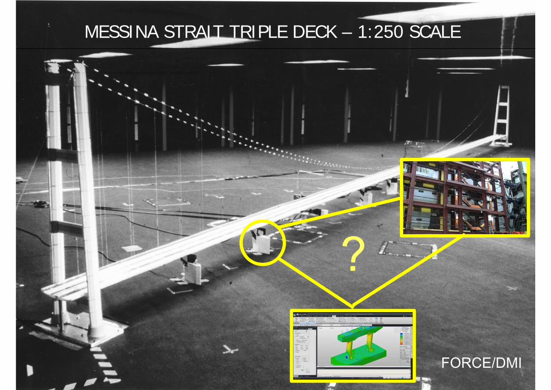
MESSINA STRAIT TRIPLE DECK – 1:250 SCALE
FORCE/DMI
?
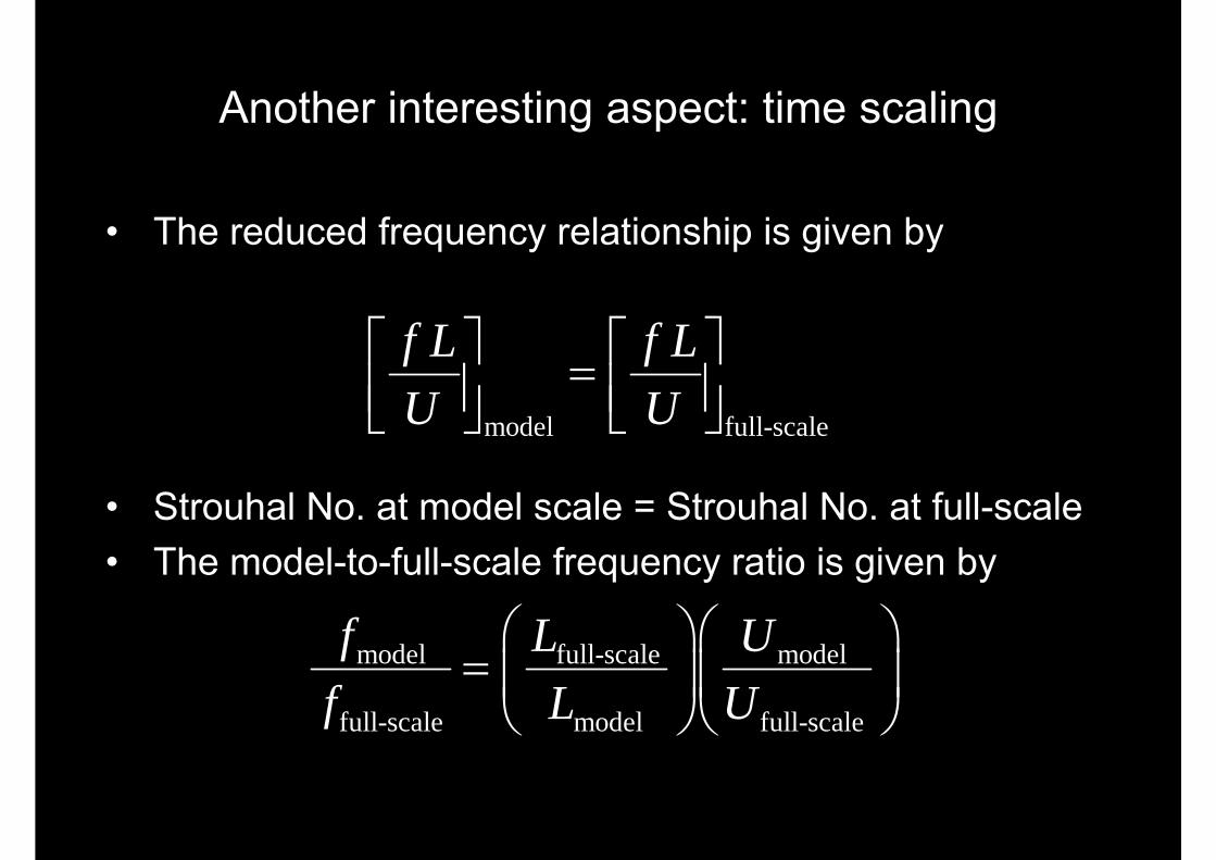
Another interesting aspect: time scaling
• The reduced frequency relationship is given by
• Strouhal No. at model scale = Strouhal No. at full-scale• The model-to-full-scale frequency ratio is given by
model full-scale
f L f LU U
model full-scale model
full-scale model full-scale
f L Uf L U
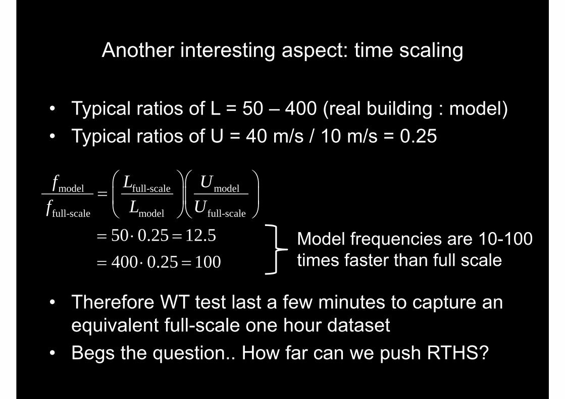
• Typical ratios of L = 50 – 400 (real building : model)• Typical ratios of U = 40 m/s / 10 m/s = 0.25
• Therefore WT test last a few minutes to capture an equivalent full-scale one hour dataset
• Begs the question.. How far can we push RTHS?
model full-scale model
full-scale model full-scale
50 0.25 12.5400 0.25 100
f L Uf L U
Model frequencies are 10-100 times faster than full scale
Another interesting aspect: time scaling
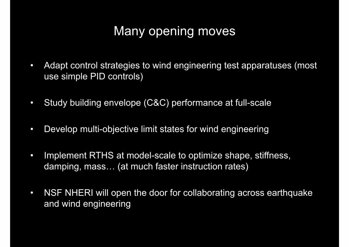
Many opening moves
• Adapt control strategies to wind engineering test apparatuses (most use simple PID controls)
• Study building envelope (C&C) performance at full-scale
• Develop multi-objective limit states for wind engineering
• Implement RTHS at model-scale to optimize shape, stiffness, damping, mass… (at much faster instruction rates)
• NSF NHERI will open the door for collaborating across earthquake and wind engineering