Embed Size (px)
Citation preview
TIME LAPSE VIDEO CASSETTE RECORDERINSTALLATION ANDOPERATION MANUAL
MODEL
HS-S8300E(BRS)
ONLY VIDEO CASSETTE TAPES WITH THE S MARK OR THE V MARK MAY BE USED WITH THIS MODEL.
THIS INSTRUCTION MANUAL IS IMPORTANT TO YOU.PLEASE READ IT BEFORE USING YOUR VIDEO CASSETTE RECORDER.
REW FF
JOG/ADJUST
CLEAR/ ENTER/
SHUTTLEREC
STOP
PLAY
POWER
EJECT
PICTURE
TRACKINGPOSITION/VERTICALADJUST
REC/PLAY MODECOUNTER
RESET
COUNTER MEMORY/SKIP/INDEX
PAUSE/SHUTTLE HOLD
DISPLAY
TIMER RECSOFT SHARP
S-VHSOFF ON
625
VHSPAL

2
CONDENSATION IS THE ENEMY OF VIDEO RECORDERS
2 WHAT IS CONDENSATION?1. When a very cold drink is poured into a glass, the water droplets which form on the outer surface of the glass are an example of
condensation.2. If the VCR is exposed to a rapid increase in temperature (such as warming a cold room or after transporting it from a cold location
to a warm one) condensation may form on the tape transport mechanism inside the VCR. To prevent damage to the VCR or tapes,plug the VCR into the mains outlet and turn the power on for about 2 hours. Do not use the VCR for playback or record during thistime.
2 CONDENSATION IS LIKELY TO OCCUR WHEN:1. The VCR is moved inside from outdoors, or from a cold room to a warm one.2. A cold room is heated quickly.3. Humidity is high.N• Avoid using the VCR where cold air (e.g., from an air conditioner) will blow directly on it.• Never place anything containing water on top of the VCR, e.g., vases, cups, etc.
HEAVY OBJECTS (E.G., TV) SHOULD NEVER BE PLACED ON THE VCR
2 MAINS LEAD CONNECTIONThe mains lead on this VCR is fitted with a non-rewireablemains plug, incorporating a 5A fuse. If you need to replacethe fuse, use a 5A fuse approved by BSI or ASTA to BS 1362,ensuring you refit the fuse cover. If the mains plug is not suit-able for the sockets in your home, buy a new mains lead. Ifyou require to remove the plug, remove the fuse, cut off theplug then dispose of the plug immediately, to avoid a possibleelectric shock hazard. To refit a new plug, follow these in-structions;Green-and-yellow: Earth,Blue: Neutral,Brown: LiveAs the colours in the mains lead of this VCR may not corre-spond with the coloured markings identifying the terminals inyour plug, proceed as follows.
• The wire which is coloured green-and-yellow must be con-nected to the terminal in the plug which is marked by the letterE or by the safety earth symbol » or coloured green or green-and-yellow.
• The wire which is coloured blue must be connected to the ter-minal which is marked with the letter N or coloured black.
• The wire which is coloured brown must be connected to theterminal which is marked with the letter L or coloured red.
CAUTION AND CARE
UNPLUGGING THE MAINS LEADWhenever unplugging the mains leads, be sure to switch off themains outlet first. Then unplug the lead by gripping the plug (notthe lead) and carefully remove the plug from the mains outlet.
NEVER TOUCH OR INSERT ANY OBJECT INSIDE THE VCRTouching the inside of the cabinet or inserting foreign objects ofany kind not only creates a safety hazard but can also cause ex-tensive damage.
PROTECT THE MAINS LEADDamage to the mains lead may cause fire or shock hazard.
UNPLUG THE MAINS LEAD DURING A LONG ABSENCEDuring a long absence, turn off the power and switch off the mainsoutlet before unplugging the mains lead.
MAINTAIN GOOD VENTILATIONDo not obstruct the many ventilation holes on the VCR. For maxi-mum ventilation, place the unit on a hard level surface only, andensure it is not covered during use. Heavy objects should neverbe placed on the VCR.
WHEN NOT IN USEWhen you finish operating the VCR always unload the cassetteand turn OFF the VCR POWER.
CABINET CARENever use petroleum-based cleaners. Clean with a soft clothmoistened with soap and water and wipe dry. PVC cables or leadsshould not be left in contact with the cabinet surface for long peri-ods.
INSTALLATION LOCATIONFor optimum performance and reliability, install the VCR in a loca-tion that is:1. Well ventilated, out of direct sunlight and away from direct heat.2. A solid vibration-free surface.3. Free from high humidity, excessive dust and away from mag-
netic fields.
N• Never move the VCR without first removing the tape.
CARE OF VIDEO CASSETTE TAPES• Avoid violent vibration or shock.• Do not place near a strong magnetic field (e.g., a motor, trans-
former or magnet).• Never place or store in direct sunlight.• Avoid dusty places.• Place the cassette in its case and store vertically.
WARNING: TO PREVENT FIRE OR SHOCK HAZARD, DONOT EXPOSE THIS APPARATUS TO RAIN ORMOISTURE.
WARNING: THIS APPARATUS MUST BE EARTHED.
This Time Lapse Video Cassette Recorder complies with the re-quirements of the EC Directive 89/336/EEC, “EMC Directive” and73/23/EEC, “Low Voltage Directive”, as amended by Directive 93/68/EEC. The requirements for the susceptibility according to EN50082-1 and the requirements for interference according to EN55022 are observed for the operation on residential areas, busi-ness, light industrial premises and in small scale enterprises, in-side as well as outside of the building. All places of operation arecharacterised by their connection to the public low voltage powersupply system.This unit is manufactured in accordance with EN60065.

3
Audio recordingWhen recording in 3H, L(linear)12H or L24H mode, audio is playedback only during their respective modes.S-VHS modeThis mode has higher resolution and picture quality than normalVHS mode when using S-VHS tapes.Tape remaining indicatorA bar indicator shows how much tape is left and/or that the tape hasapproximately three minutes (in 3H mode) left.Automatic head clog detection and cleaningFor continuous smooth operation, the VCR automatically detectsand cleans up foreign matter while recording, simultaneously sensingthe output from the video heads.Easy setting using a monitorThe on-screen menus simplify setting-up procedures. These menuscan be selected even without the input of a video signal.Easy cueing with alarm recordingIndex signals are added automatically at the beginning of “alarmrecording” for easy cueing. You can confirm the Alarm starting timein the playback video on the monitor with the Alarm list using theMaintenance menu.Time date search systemInput the day and time you want to view and the VCR will search anddisplay it automatically.External time clock adjustmentThe on-screen time clock can be reset to the nearest hour by applyinga signal to the RST(RESET) IN terminal at the rear of the VCR.Automatic azimuth head selectionThis VCR can automatically select playback heads for normal VHScompatible Time Lapse recordings, or older Time Lapse recordingsmade using two Same Azimuth video heads. Same Azimuth TimeLapse recordings use VHS cassettes but cannot be played normallyby VHS compatible VCRs.
Full lock modeLocking prevents the VCR from being operated by an unauthorisedthird party.Special playback featuresThese include still images, speed search, reverse playback, frame-by-frame viewing in both directions, slow motion and high speed viewing.JOG dial/SHUTTLE ringUse to search for the desired image. You can adjust the playbackspeed with the SHUTTLE ring and search for an image frame byframe with the JOG dial.Record checkCorrect recording can be confirmed by pressing the PLAY buttonduring recording.Recording optionsThis versatile system offers a variety of recording options, includingdaily and weekly timer recording, repeat and alarm recording.Protection against power failuresRecording data including date, time and timer set-up, are stored inbackup memory, so the system can resume recording after a powerfailure. The time of the failure is displayed on the monitor.Digital <ELAPSED TIME> displayThe Elapsed Time of recording and playback is stored in a non-volatile memory IC. The elapsed time display should be used as aguide as to when periodic maintenance should be carried out.Tape use counterDisplays how many times you have repeatedly recorded on a tape.This is helpful for deciding when it is necessary to replace a tape.Connection with a personal computerWhen connecting with a personal computer equipped with RS-232Cconnector, you can operate this VCR by remote control or control bythis VCR automatically. Up to 16 VCRs may be connected in seriesand controlled from a single RS-232C port of a personal computer.Daylight saving time settingDaylight saving time setting is available. The clock can be put forwardby one hour by setting the menu.
CONTENTSPages
Elapsed time display ............................................................ 19TIMER RECORDING ....................................................... 20 - 21ALARM RECORDING ..................................................... 22 - 24
Alarm recording connection ................................................. 22External time clock adjustment ............................................ 22Setting for alarm recording .................................................. 23Emergency recording........................................................... 23Alarm record time display .................................................... 24Locating the start of alarm recordings ................................. 24
PLAYBACK ............................................................................. 25Audio playback ..................................................................... 25
SPECIAL EFFECTS PLAYBACK ........................................... 26ADJUSTMENT DURING PLAYBACK
Tracking adjustment ............................................................. 27Picture quality adjustment .................................................... 27Vertical adjustment .............................................................. 27
USING WITH THE PERSONAL COMPUTER ................. 28 - 36WARNING DISPLAY............................................................... 37BEFORE CALLING FOR SERVICE ....................................... 38CONTROL INPUT/OUTPUT SIGNALS AND CIRCUITS ..... 39 - 40SPECIFICATIONS .................................................................. 41
FEATURESUp to 960 hours of recording: an ideal video system for automated security and surveillance systems.
PagesFEATURES AND FUNCTIONS
Front view ............................................................................... 4Fluorescent display ................................................................. 5Rear view ................................................................................ 6
CONNECTING WITH OTHER EQUIPMENT ............................. 7SETTING THE MENUS .......................................................8 - 12SETTING THE PRESENT TIME ....................................... 13 -14LOADING AND UNLOADING THE CASSETTE TAPE .......... 15MANUAL RECORDING ....................................................16 - 18
Audio recording ..................................................................... 16Repeat recording .................................................................. 17Series recording ................................................................... 17One shot/Interval recording .................................................. 18Synchronous recording ......................................................... 18
ADDITIONAL FEATURESCounter memory ................................................................... 19Tape counter ......................................................................... 19Counter reset ........................................................................ 19Memory back-up in case of power failure ............................. 19Recording after a power failure ............................................. 19Power failure time display ..................................................... 19
This time lapse VCR is designed especially for industrial, educational and security recording. In addition to ordinary 3-hour recordingmode, it has time lapse modes that allow recording of 12, 24, 48, 72, 96, 120, 168, 240, 360, 480, 720 or 960 hours. Also, the recordingtime can be extended up to 27,000 hours (for E-180 cassette tape) if you choose one-shot recording with 3 minutes interval time.Frame-by-frame playback and high-speed playback of longer recordings are also available. This adds up to a powerful surveillancesystem for banks, buildings, traffic and parking lots, as well as a convenient scientific tool for observation of plant growth, animalbehaviour and other time-intensive processes.
4
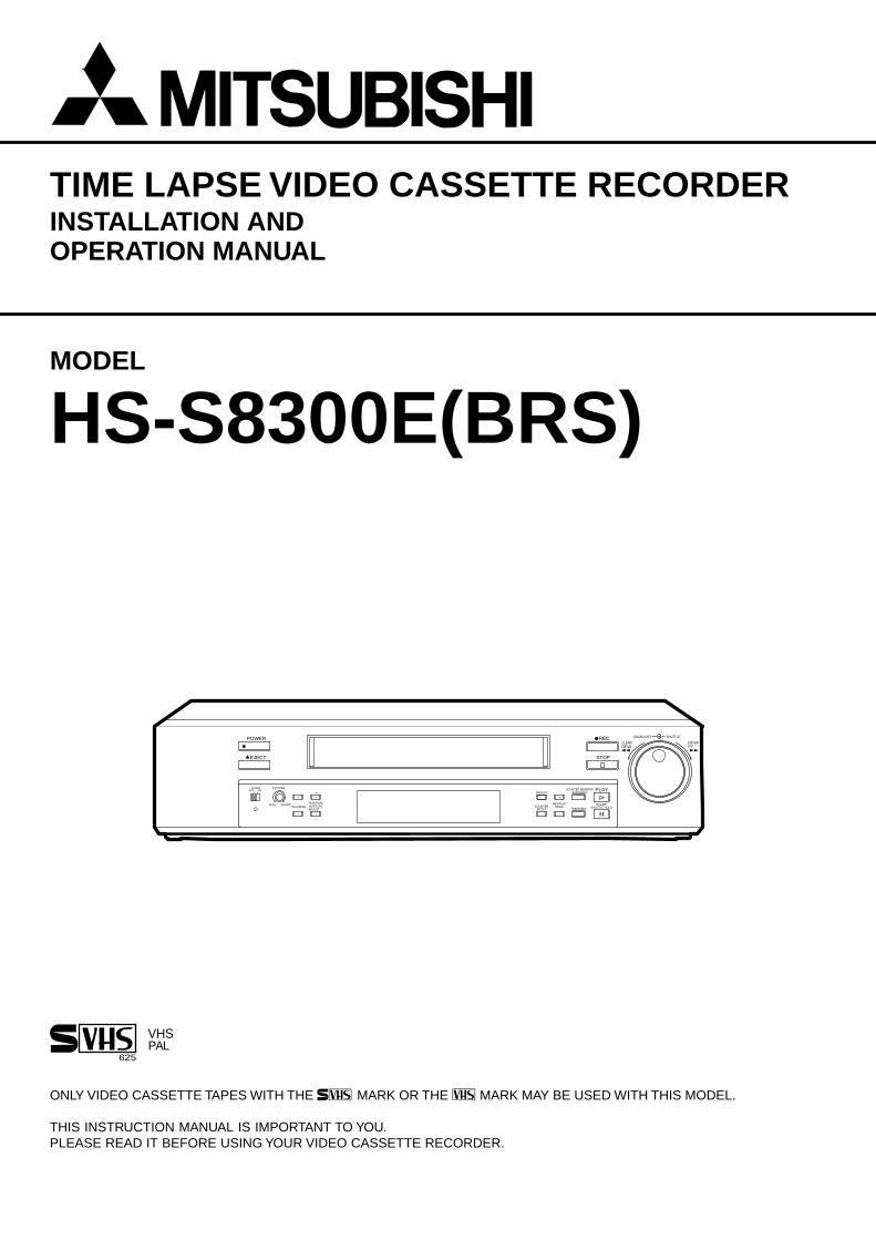
1 POWER button (Press for on; press again for off)The POWER indicator illuminates when the VCR isswitched on.
2 EJECT buttonPress to remove the cassette.
3 Cassette loading slotCassette tape is inserted in this slot for loading.
4 STOP buttonPress to discontinue all tape related functions.
5 REC (RECORD) buttonPress to begin recording.
6 JOG dialUse to forward the tape frame-by-frame and to set themenus.
7 SHUTTLE ringUse to adjust the playback speed or to set the menus.Turn this ring to the right to forward a tape or to forwardsearch. Turn this ring to the left to rewind a tape or toreverse search. Also use to clear the alarm list, powerloss list and timer recording and to initialize the menusettings.
8 PLAY buttonPress to playback a previously recorded tape.
9 PAUSE/SHUTTLE HOLD buttonWhen pressed during recording, tape movement stopstemporarily. Press again to continue the recording.When pressed during playback, tape movement stopsand a still field is displayed. Press again to restore normalplayback. Pressing and holding this button after turningthe SHUTTLE ring allows continuous high speed playbackeven if the SHUTTLE ring is released.
A COUNTER MEMORY/SKIP/INDEX buttonUse to switch between COUNTER MEMORY (P.19), SKIPSEARCH or INDEX SEARCH (P.24).
B TIMER REC buttonThis button is pressed when a timer recording is to bemade.
FEATURES AND FUNCTIONS FRONT VIEW
C REC/PLAY MODE buttonsSet to 3H, L12H, L24H, 48H - 960H or 0H mode to selectrecording speed. Set to 3H, L12H, 12H, L24H, 24H, 48H- 960H or 0H mode to select playback speed duringplayback recorded in SP mode.
D COUNTER RESET buttonPress to reset the counter to “00000”.
E DISPLAY buttonPress to display the MAIN MENU.Press again to show the present time display.
F POSITION/VERTICAL ADJUST buttons• When (+) button is pressed, the day and present time
display will move to the right. When the (-) button ispressed, the day and present time will move down thescreen. Cannot be adjusted if a warning is displayed.
• Press these buttons to adjust for vertical vibrations whenin still mode or during fast playback. Refer to pages 7and 27 for more details.
G TRACKING buttons (+/-)Press these buttons if noise is present during playback,reverse playback or slow playback.
H PICTURE controlThe picture quality can be adjusted between soft andsharp.
I LOCK buttonWhen pressed with a ball-point pen or a pencil, the unitwill be locked into the current mode and the operationbuttons will not operate. Release the lock by pressingthe lock button again.
J S-VHS switchUsed to select ON/OFF S-VHS mode while recording.ON : Resumes S-VHS mode recording when using S-
VHS cassette.OFF : Recording takes place in VHS mode with both
VHS and S-VHS cassette.
REW FF
JOG/ADJUST
CLEAR/ ENTER/
SHUTTLEREC
STOP
PLAY
POWER
EJECT
PICTURE
TRACKINGPOSITION/VERTICALADJUST
REC/PLAYMODECOUNTER
RESET
COUNTER MEMORY/SKIP/INDEX
PAUSE/SHUTTLE HOLD
DISPLAY
TIMER REC
S-VHS
SOFT SHARP
OFF ON
Fluorescent display
2 1 3 5 64
8ED
CB 9A
7FGHI
J
5
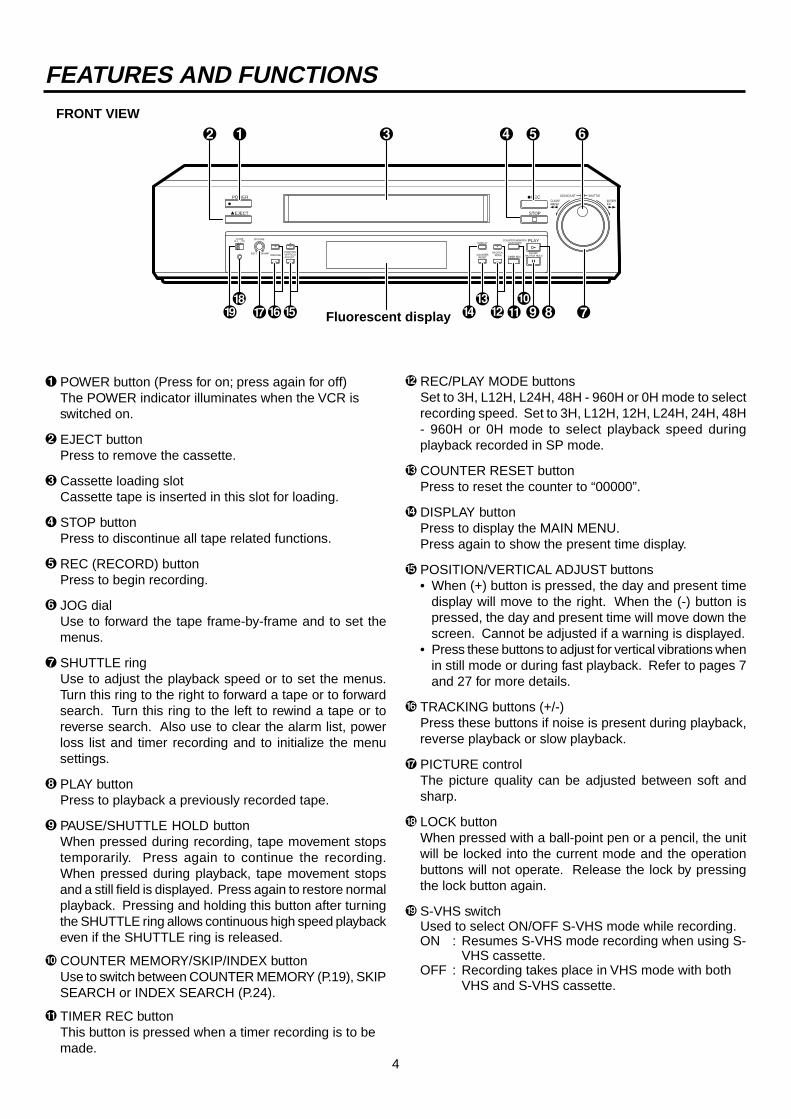
9 Repeat indicatorIlluminates when “TAPE END” in the “FIRST TIME SETUP” menu is set to “REPEAT” or “ALARM•PROT”.
A Cassette status indicatorIlluminates when cassette tape is inserted. The lightadvances, stops or flashes corresponding to themovement of the tape.
B Timer recording indicatorIlluminates when the TIMER REC button is set to ON.
C Tape remaining indicatorIndicates the approximate tape position. S=Start,E=End.
D REC indicatorIlluminates during recording.
E PLAY indicatorIlluminates during playback.
F EMGCY (EMERGENCY REC) indicatorIlluminates when “EMERGENCY REC” of the“RECORDING SET UP” menu is set to “ON”.
G LOCK indicatorLights when the Lock mode is set.
H COUNTER displayIndicates the relative position on the tape.
1 M (COUNTER MEMORY) indicatorIlluminates during rewind for counter memory mode.
2 PL (POWER LOSS) indicatorIlluminates when there is a power failure during recording.
3 ALARM indicatorFlashes during alarm recording and stays on when thealarm recording is finished.
4 INDEX indicatorFlashes during recording of date/hour index signal at thechange of the hour, and during recording of the alarmindex signal. Lights during index search and the settingof Index search.
5 MODE displayDisplays the selected recording or playback mode. Duringindex search, displays the index number. It will alsoindicate the playback head selection, “SH” or “AH”, 3seconds after the playback starts or if the playback modeis changed. In the “FIRST TIME SET UP” menu, if the“PB HEAD SELECT” is set to “L/L” or “R/R” then “SH” willilluminate. If set to “AUTO”, then “AH” will illuminate.
6 SKIP indicatorIlluminates during skip search.
7 Record mode indicatorSP illuminates to indicate recording in SP mode or playingback a tape recorded in SP mode.
8 S-VHS indicatorThis indicator illuminates when the VCR is playing backa tape recorded in the S-VHS mode or when the S-VHSswitch is ON while recording.
FLUORESCENT DISPLAY
PLAYEMGCYH
SKIP S E
LOCK
M PLSP
ALARM INDEX MODE
REC
VHS S
C1 2 43 5 6 7 8 9A
G F E DH
B
6
FEATURES AND FUNCTIONS
REAR VIEW
N• Ensure the power cord is not plugged into the mains outlet before connecting to any rear terminals.
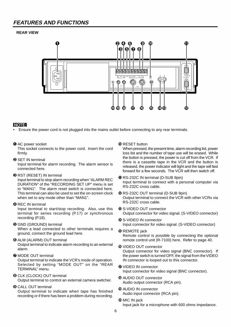
1 AC power socketThis socket connects to the power cord. Insert the cordfirmly.
2 SET IN terminalInput terminal for alarm recording. The alarm sensor isconnected here.
3 RST (RESET) IN terminalInput terminal to stop alarm recording when “ALARM RECDURATION” of the “RECORDING SET UP” menu is setto “MAN1”. The alarm reset switch is connected here.This terminal can also be used to set the on-screen clockwhen set to any mode other than “MAN1”.
4 REC IN terminalInput terminal to start/stop recording. Also, use thisterminal for series recording (P.17) or synchronousrecording (P.18).
5 GND (GROUND) terminalWhen a lead connected to other terminals requires aground, connect the ground lead here.
6 ALM (ALARM) OUT terminalOutput terminal to indicate alarm recording to an externalalarm.
7 MODE OUT terminalOutput terminal to indicate the VCR’s mode of operation.Selected by setting “MODE OUT” on the “REARTERMINAL” menu.
8 CLK (CLOCK) OUT terminalOutput terminal to control an external camera switcher.
9 CALL OUT terminalOutput terminal to indicate when tape has finishedrecording or if there has been a problem during recording.
A RESET buttonWhen pressed, the present time, alarm recording list, powerloss list and the number of tape use will be erased. Whilethe button is pressed, the power is cut off from the VCR. Ifthere is a cassette tape in the VCR and the button isreleased, the power indicator will light and the tape will fastforward for a few seconds. The VCR will then switch off.
B RS-232C IN terminal (D-SUB 9pin)Input terminal to connect with a personal computer viaRS-232C cross cable.
C RS-232C OUT terminal (D-SUB 9pin)Output terminal to connect the VCR with other VCRs viaRS-232C cross cable.
D S-VIDEO OUT connectorOutput connector for video signal. (S-VIDEO connector)
E S-VIDEO IN connectorInput connector for video signal. (S-VIDEO connector)
F REMOTE jackRemote control is possible by connecting the optionalremote control unit (R-7100) here. Refer to page 40.
G VIDEO OUT connectorOutput connector for video signal (BNC connector). Ifthe power switch is turned OFF, the signal from the VIDEOIN connector is looped out to this connector.
H VIDEO IN connectorInput connector for video signal (BNC connector).
I AUDIO OUT connectorAudio output connector (RCA pin).
J AUDIO IN connectorAudio input connector (RCA pin).
K MIC IN jackInput jack for a microphone with 600 ohms impedance.
VIDEOOUTIN
IN OUTÉMICAUDIO
RESET
REMOTE
SET RSTIN
REC GND ALM MODE CLK CALLOUT
IN OUTS-VIDEO
OUT
INRS-232C
1
5
2
3
4 67 8
9 A B
ED CFGHK J I

7
CONNECTING WITH OTHER EQUIPMENT
AUDIO OUT
MIC IN
VIDEO OUT
VIDEO IN
AUDIO IN
MONITOR
SET IN
SENSOR
VIDEOOUT
CCTVCAMERA
VIDEO IN
MIC
VIDEOOUTIN
IN OUTMICAUDIO
RESET
REMOTE
SET RSTIN
REC GND ALM MODE CLK CALLOUT
IN OUTS-VIDEO
OUT
INRS-232C
VERTICAL ADJUSTMENT (Correcting picture vibration at the top and bottom)
The picture vibration can be reduced or eliminated by the following steps.1 If the vibration occurs in still, slow motion, fast playback (x2) or normal playback in 12H - 960H or 0H mode,
playback a tape which is recorded in 3H mode with this VCR and press the PAUSE button.If the vibration occurs during normal playback in L12H or L24H mode, playback a tape in each playback mode.
2 Press the VERTICAL ADJUST (+) or (-) button to reduce or eliminate the picture vibration.
N• When QUASI V-SYNC is set to “OFF”, the picture vibration is not adjustable with the VERTICAL ADJUST buttons.
MONITOR TO BE CONNECTED
• Connection with a CCTV monitor (for surveillance) is recommended.• Connecting with some monitors may cause picture vibration and/or picture distortion at the top or bottom of the image
during still or normal playback.A domestic Television used as a Monitor may be unable to provide a stable picture without vibration and distortion.
8
11 – 11 – 99 09 : 21 : 01
<RECORDING SET UP>3H1M
OFF1
SHOT
<MAIN MENU> DISPLAY TIME DATE SEARCH TIMER PROGRAM RECORDING SET UP REAR TERMINAL MAINTENANCE FIRST TIME SET UPUse JOG to select, and ENTER.Press DISPLAY to exit.
ALARM REC MODEALARM REC DURATIONEMERGENCY RECONESHOT•FIELDONESHOT•INTERVAL
<REAR TERMINAL>WRNG•TAPE END
REC- 1REC
SERIES
CALL OUTCLOCK OUTMODE OUTREC IN
00H
<MAINTENANCE>POWER LOSS LISTALARM LISTALL MENU INITIALIZEPOWER LOSS LIST CLEARALARM LIST CLEAR
<REPEAT REC TIMES><ELAPSED TIME>
<FIRST TIME SET UP>TAPE ENDQUASI V-SYNCTAPE LENGTHVIDEO MODEPB HEAD SELECTBUZZERTIME DATE ADJUSTRS-232C
STOPON
E-180COLOURNORMAL
WRNG
OFF111199
09 :21 : 01
<TIME DATE SEARCH>15:00
23FORWARD
TIMEDATEDIRECTION
Use JOG to adjust, and ENTER.
<DISPLAY>1
SMALLON
11 - 11 - 99 09 : 21 : 01
DISPLAY MODETIME DATE SIZEBLUE BACK
Ex.<MODE 1>
<TIMER PROGRAM>DW START END HR
SPL 08 : 40 17 : 10 L12SP 2 SAT 08 : 40 12 : 20 L12SP 3 WED 22 : 00 22 : 54 3SP 4 - - - - - : - - - - : - - - - -5 - - - - - : - - - - : - - - - -6 - - - - - : - - - - : - - - - -7 - - - - - : - - - - : - - - - -8 - - - - - : - - - - : - - - - - SPECIAL DW MON–FRI
<ALARM LIST>
ALL MENU INITIALIZE
Turn the SHUTTLE RING <<then all MENU will beinitialized.
POWER LOSS LIST CLEAR
Turn the SHUTTLE RING <<then POWER LOSS LISTwill be cleared.
ALARM LIST CLEAR
Turn the SHUTTLE RING <<then ALARM LIST will be cleared.
0001 01 - 05 - 99 01 : 000002 01 - 07 - 99 21 : 100003 01 - 10 - 99 09 : 15
<POWER LOSS LIST>01 01 - 03 - 99 01 : 000203
DAYLIGHT SAVINGSDATEMONTHYEARTIME
<TIME DATE ADJUST>
<RS-232C>TRANSMISSION RATEDATA BIT LENGTHSTOP BIT LENGTHPARITY BITDELIMITTER<SEND>DELIMITTER<RECEIVE>VCR ADDRESS
12008BIT1BIT
NONECRCR
NONE
SETTING THE MENUS
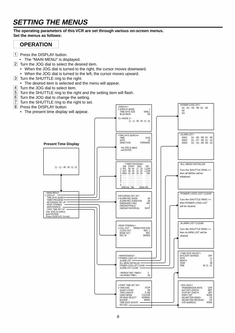
1 Press the DISPLAY button.• The “MAIN MENU” is displayed.
2 Turn the JOG dial to select the desired item.• When the JOG dial is turned to the right, the cursor moves downward.• When the JOG dial is turned to the left, the cursor moves upward.
3 Turn the SHUTTLE ring to the right.• The desired item is selected and the menu will appear.
4 Turn the JOG dial to select item.5 Turn the SHUTTLE ring to the right and the setting item will flash.6 Turn the JOG dial to change the setting.7 Turn the SHUTTLE ring to the right to set.8 Press the DISPLAY button.
• The present time display will appear.
The operating parameters of this VCR are set through various on-screen menus.Set the menus as follows:
OPERATION
Present Time Display

9
<MAIN MENU> DISPLAY TIME DATE SEARCH TIMER PROGRAM RECORDING SET UP REAR TERMINAL MAINTENANCE FIRST TIME SET UPUse JOG to select, and ENTER.Press DISPLAY to exit.
<DISPLAY>1
SMALLON
11 – 11 – 99 09 : 21 : 01
DISPLAY MODETIME DATE SIZEBLUE BACK
Ex.<MODE 1>
<TIME DATE SEARCH>15:00
23FORWARD
TIMEDATEDIRECTION
Use JOG to adjust, and ENTER.
MAIN MENU1 DISPLAY
Sets the display format of the date and present time on the monitor.
2 TIME DATE SEARCHSets the date, time and direction to search for the desired location on a tape.
3 TIMER PROGRAMSets the timer recording.
4 RECORDING SET UPSets the alarm recording mode, alarm recording duration, emergency recording, recording mode and one-shot recording.
5 REAR TERMINALSets the frequency division ratio of CLOCK OUT, output signal of the CALL OUT terminal and the MODE OUT terminal, etc.
6 MAINTENANCEDisplays the power loss list and alarm loss list, etc. and initialises all menu settings. Clears the power loss list and alarm list.
7 FIRST TIME SET UPSet up for when the end of the tape is reached, quasi v-sync, tape length, playback head selection, buzzer setting and present time.
DISPLAY1 SETTING THE DISPLAY MODE (DISPLAY MODE)
DISPLAY MODE 1: Displays date and present time. (Refer to page 13.)DISPLAY MODE 2: Displays date, day of the week, present time and recording mode. (Refer to
page 13.)DISPLAY MODE 3: Displays nothing; until an alarm recording starts, then date, alarm recording
number, etc. is displayed.DISPLAY MODE 4: Displays nothing; even in the case of alarm recording, nothing is displayed
on the monitor.• During an alarm recording, alarm recording number is displayed if the “DISPLAY MODE” is set from 1 to 3.
2 SETTING THE SIZE OF THE LETTERS OF DAY AND PRESENT TIME DISPLAY (TIME DATE SIZE)SMALL: The size of the letters becomes small.LARGE: The size of the letters becomes large.
3 SETTING THE BACKGROUND COLOUR (BLUE BACK)ON: The blue screen overlays on the recorded picture when menu is displayed on the monitor.OFF: The blue screen will be replaced by the recorded picture overlaid with the menu display.N• The above setting will also affect the background colour when there is no recording input signal. When BLUE BACK is set to
“ON”, the warning, “NO SIGNAL” appears on the blue screen and when set to “OFF”, the blue screen or warning does notappear on the monitor.
TIME DATE SEARCHSets the date, time and direction to search for the desired location on a tape.
1 SETTING THE TIME Turn the JOG dial to set the hour and minute to search for.
2 SETTING THE DATE Turn the JOG dial to set the day of the month to search for.
3 SETTING THE DIRECTION Turn the JOG dial to select the starting direction for search.FORWARD: Search in the forward direction.REVERSE: Search in the reverse direction.• If the desired part of a tape is not found in one direction, the VCR automatically searches in the opposite direction.
After the setting, turn the SHUTTLE ring to the right to start searching.N• An hour index mark is written on the tape on the hour and is used as a reference in the search function. Because of this, a
recorded tape must pass a time clock hour mark before this function can work. The TIME DATE SEARCH function begins afterthe first hour index mark.Example 1: VCR is set to record from 8:30 to 17:30 - Times from 9:00 to 17:30 can be found.Example 2: VCR is set to record in one speed from 7:00 to 14:30, then in another speed until 18:00.
- Times from 7:00 to 14:30 and 15:00 to 18:00 are accurately located.• Time date search function is not available for a tape recorded by any other VCR than this model.• If recording quality is poor, the VCR may fail to locate the desired part of the tape during time date search.
TIMER PROGRAMRefer to page 20, “TIMER RECORDING” for details.

10
CALL OUT settingTAPE END
settingWRNG•TAPE END WRNG
STOPOutputs a call signal at the
end of the tape
Outputs a call signal at theend of the tape for 2 seconds
Outputs a call signal at theend of the tape
When a malfunction occurs in the VCRduring recording, a call signal is output.
REWIND
REPEAT
ALARM• PROT
When there are noalarm recordingsduring recording
When there are alarmrecordings during
recording
WRNG•REMAIN
Outputs 3 minutes beforethe tape end
SETTING THE MENUS
<REAR TERMINAL>WRNG•TAPE END
REC- 1REC
SERIES
CALL OUTCLOCK OUTMODE OUTREC IN
REAR TERMINAL
1 SETTING THE CALL SIGNAL OUTPUT AT THE END OF THE TAPE (CALL OUT)Enables or disables the signal that is output from the CALL terminal when the end of the tape isreached during recording. If any abnormalities occur during recording, a CALL signal is output fromthe CALL terminal on the rear panel regardless of CALL OUT setting.
WRNG•TAPE END: A signal is output at the end of the tape or when a malfunction occurs.WRNG•REMAIN: The signal is output when a malfunction occurs in this VCR or when the
tape has approximately 3 minutes left in 3H mode.WRNG: When a malfunction occurs in the VCR during recording, a CALL signal is
output.
This is used in conjunction with TAPE END (FIRST TIME SET UP) to determine when the CALL signal is output as shown below.
RECORDING SET UP
1 SETTING THE ALARM REC MODE (ALARM REC MODE)
Sets the alarm recording time mode. When the JOG dial is turned, the display will be switched in theorder of 3H L12H L24H 3H ....
2 SETTING THE ALARM REC DURATION (ALARM REC DURATION)
Sets the duration of the alarm recording period. When the JOG dial is turned, the display will beswitched in the order of 1M(minute) 2M 5M 10M MAN1 MAN2 15S(second) 30S 45S 1M .... Refer to “ALARM RECORDING” on page 22.
3 SETTING THE EMERGENCY REC (EMERGENCY REC)
Sets the emergency recording mode.
OFF: Starts alarm recording when the alarm signal is received during recording.ON: Starts alarm recording when the alarm signal is received not only during recording but also when the power is OFF or
when the tape is stopped.N• When “ON” is selected, the alarm recording begins even though the recorder is in recording standby mode.
4 SETTING THE NUMBER OF FIELDS IN ONE-SHOT RECORDING (ONE SHOT•FIELD)
Sets the number of recorded fields in the one-shot recording mode. When the JOG dial is turned to the right, the display will beswitched in the order of 1 2 3 4 5 10 20 30 1 ....
5 SETTING THE INTERVAL TIME IN THE ONE-SHOT RECORDING MODE (ONE SHOT•INTERVAL)
Sets the interval time in the one-shot recording mode. When the JOG dial is turned to the right, the display will be switched in theorder of SHOT 10S (second) 15S 30S 45S 1M 2M 3M SHOT ....
<RECORDING SET UP>3H1M
OFF1
SHOT
ALARM REC MODEALARM REC DURATIONEMERGENCY RECONESHOT•FIELDONESHOT•INTERVAL
11
MAINTENANCE
1 DISPLAYING THE POWER LOSS LIST (POWER LOSS LIST)
Turn the JOG dial to select “POWER LOSS LIST”. Turn the SHUTTLE ring to the right to display thePower Loss List. Power failure start times are stored in memory, so it is possible to confirm whenthey have occurred. Up to 3 power failure start times will be displayed. If more than 3 failures haveoccurred, the first and last 2 power failure start times will be displayed.
2 DISPLAYING THE ALARM LIST (ALARM LIST)
Turn the JOG dial to select “ALARM LIST”. Turn the SHUTTLE ring to the right to display the Alarm List. Alarm record starttimes are stored in memory, so it is possible to confirm when they have occurred. Up to 3 alarm record start times will bedisplayed. If more than 3 alarm records have occurred, the first and the last 2 alarm record start times will be displayed.
3 INITIALIZING ALL MENU SETTINGS (ALL MENU INITIALIZE)
Turn the SHUTTLE ring to the right and “ALL MENU INITIALIZE” will be displayed. When the SHUTTLE ring is turned to the left,each setting is initialised except the TIMER RECORDING setting. When the SHUTTLE ring is turned to the right, the“MAINTENANCE” menu will be displayed.
4 CLEARING THE POWER LOSS LIST (POWER LOSS LIST CLEAR)
Turn the SHUTTLE ring to the right and “POWER LOSS LIST CLEAR” will be displayed. When the SHUTTLE ring is turned tothe left, the Power Loss List is cleared. When the SHUTTLE ring is turned to the right, the “MAINTENANCE” menu will bedisplayed.
5 CLEARING THE ALARM LIST (ALARM LIST CLEAR)
Turn the SHUTTLE ring to the right and “ALARM LIST CLEAR” will be displayed. When the SHUTTLE ring is turned to the left,the alarm list is cleared. When the SHUTTLE ring is turned to the right, the “MAINTENANCE” menu will be displayed.
00H
<MAINTENANCE>POWER LOSS LISTALARM LISTALL MENU INITIALIZEPOWER LOSS LIST CLEARALARM LIST CLEAR
<REPEAT REC TIMES><ELAPSED TIME>
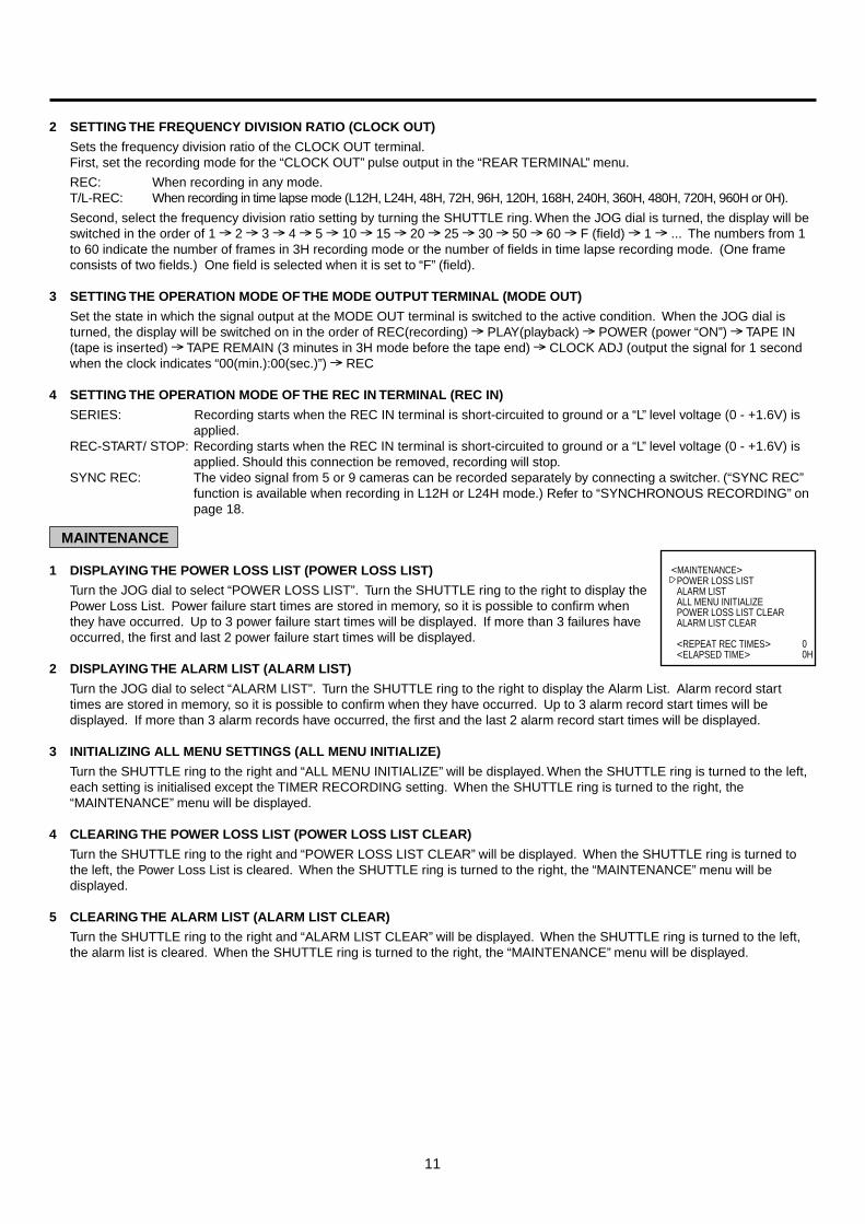
2 SETTING THE FREQUENCY DIVISION RATIO (CLOCK OUT)
Sets the frequency division ratio of the CLOCK OUT terminal.First, set the recording mode for the “CLOCK OUT” pulse output in the “REAR TERMINAL” menu.
REC: When recording in any mode.T/L-REC: When recording in time lapse mode (L12H, L24H, 48H, 72H, 96H, 120H, 168H, 240H, 360H, 480H, 720H, 960H or 0H).
Second, select the frequency division ratio setting by turning the SHUTTLE ring. When the JOG dial is turned, the display will beswitched in the order of 1 2 3 4 5 10 15 20 25 30 50 60 F (field) 1 ... The numbers from 1to 60 indicate the number of frames in 3H recording mode or the number of fields in time lapse recording mode. (One frameconsists of two fields.) One field is selected when it is set to “F” (field).
3 SETTING THE OPERATION MODE OF THE MODE OUTPUT TERMINAL (MODE OUT)
Set the state in which the signal output at the MODE OUT terminal is switched to the active condition. When the JOG dial isturned, the display will be switched on in the order of REC(recording) PLAY(playback) POWER (power “ON”) TAPE IN(tape is inserted) TAPE REMAIN (3 minutes in 3H mode before the tape end) CLOCK ADJ (output the signal for 1 secondwhen the clock indicates “00(min.):00(sec.)”) REC
4 SETTING THE OPERATION MODE OF THE REC IN TERMINAL (REC IN)
SERIES: Recording starts when the REC IN terminal is short-circuited to ground or a “L” level voltage (0 - +1.6V) isapplied.
REC-START/ STOP: Recording starts when the REC IN terminal is short-circuited to ground or a “L” level voltage (0 - +1.6V) isapplied. Should this connection be removed, recording will stop.
SYNC REC: The video signal from 5 or 9 cameras can be recorded separately by connecting a switcher. (“SYNC REC”function is available when recording in L12H or L24H mode.) Refer to “SYNCHRONOUS RECORDING” onpage 18.
12
FIRST TIME SET UP
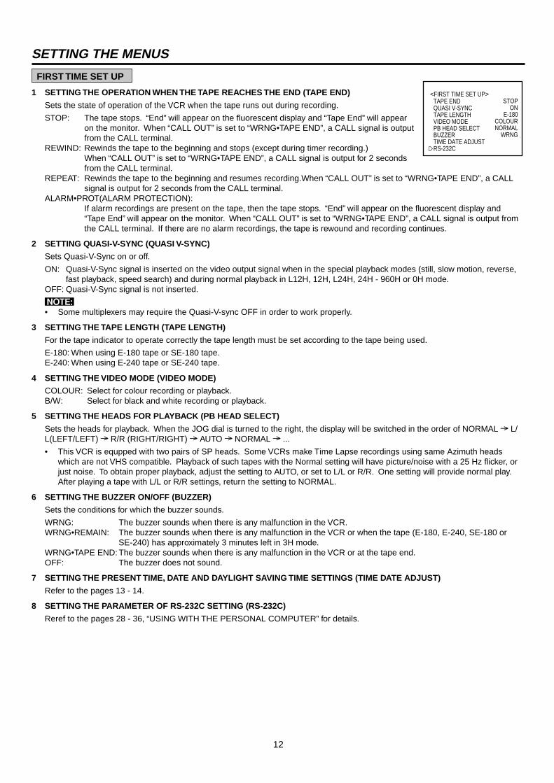
1 SETTING THE OPERATION WHEN THE TAPE REACHES THE END (TAPE END)
Sets the state of operation of the VCR when the tape runs out during recording.
STOP: The tape stops. “End” will appear on the fluorescent display and “Tape End” will appearon the monitor. When “CALL OUT” is set to “WRNG•TAPE END”, a CALL signal is outputfrom the CALL terminal.
REWIND: Rewinds the tape to the beginning and stops (except during timer recording.)When “CALL OUT” is set to “WRNG•TAPE END”, a CALL signal is output for 2 secondsfrom the CALL terminal.
REPEAT: Rewinds the tape to the beginning and resumes recording.When “CALL OUT” is set to “WRNG•TAPE END”, a CALLsignal is output for 2 seconds from the CALL terminal.
ALARM•PROT(ALARM PROTECTION):If alarm recordings are present on the tape, then the tape stops. “End” will appear on the fluorescent display and“Tape End” will appear on the monitor. When “CALL OUT” is set to “WRNG•TAPE END”, a CALL signal is output fromthe CALL terminal. If there are no alarm recordings, the tape is rewound and recording continues.
2 SETTING QUASI-V-SYNC (QUASI V-SYNC)
Sets Quasi-V-Sync on or off.
ON: Quasi-V-Sync signal is inserted on the video output signal when in the special playback modes (still, slow motion, reverse,fast playback, speed search) and during normal playback in L12H, 12H, L24H, 24H - 960H or 0H mode.
OFF: Quasi-V-Sync signal is not inserted.
N• Some multiplexers may require the Quasi-V-sync OFF in order to work properly.
3 SETTING THE TAPE LENGTH (TAPE LENGTH)
For the tape indicator to operate correctly the tape length must be set according to the tape being used.
E-180: When using E-180 tape or SE-180 tape.E-240: When using E-240 tape or SE-240 tape.
4 SETTING THE VIDEO MODE (VIDEO MODE)
COLOUR: Select for colour recording or playback.B/W: Select for black and white recording or playback.
5 SETTING THE HEADS FOR PLAYBACK (PB HEAD SELECT)
Sets the heads for playback. When the JOG dial is turned to the right, the display will be switched in the order of NORMAL L/L(LEFT/LEFT) R/R (RIGHT/RIGHT) AUTO NORMAL ...
• This VCR is equpped with two pairs of SP heads. Some VCRs make Time Lapse recordings using same Azimuth headswhich are not VHS compatible. Playback of such tapes with the Normal setting will have picture/noise with a 25 Hz flicker, orjust noise. To obtain proper playback, adjust the setting to AUTO, or set to L/L or R/R. One setting will provide normal play.After playing a tape with L/L or R/R settings, return the setting to NORMAL.
6 SETTING THE BUZZER ON/OFF (BUZZER)
Sets the conditions for which the buzzer sounds.
WRNG: The buzzer sounds when there is any malfunction in the VCR.WRNG•REMAIN: The buzzer sounds when there is any malfunction in the VCR or when the tape (E-180, E-240, SE-180 or
SE-240) has approximately 3 minutes left in 3H mode.WRNG•TAPE END: The buzzer sounds when there is any malfunction in the VCR or at the tape end.OFF: The buzzer does not sound.
7 SETTING THE PRESENT TIME, DATE AND DAYLIGHT SAVING TIME SETTINGS (TIME DATE ADJUST)
Refer to the pages 13 - 14.
8 SETTING THE PARAMETER OF RS-232C SETTING (RS-232C)
Reref to the pages 28 - 36, “USING WITH THE PERSONAL COMPUTER” for details.
<FIRST TIME SET UP>TAPE ENDQUASI V-SYNCTAPE LENGTHVIDEO MODEPB HEAD SELECTBUZZERTIME DATE ADJUSTRS-232C
STOPON
E-180COLOURNORMAL
WRNG
SETTING THE MENUS
13
SETTING THE PRESENT TIMEACCURATELY PRESET THE DAY AND PRESENT TIME BEFORE TIMER PROGRAMMING
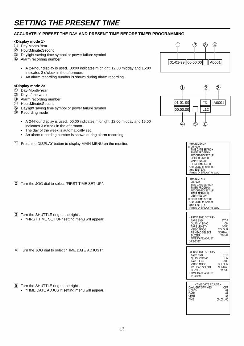
<Display mode 1>1 Day-Month-Year2 Hour:Minute:Second3 Daylight saving time symbol or power failure symbol4 Alarm recording number
• A 24-hour display is used. 00:00 indicates midnight; 12:00 midday and 15:00indicates 3 o’clock in the afternoon.
• An alarm recording number is shown during alarm recording.
<Display mode 2>1 Day-Month-Year2 Day of the week3 Alarm recording number4 Hour:Minute:Second5 Daylight saving time symbol or power failure symbol6 Recording mode
• A 24-hour display is used. 00:00 indicates midnight; 12:00 midday and 15:00indicates 3 o’clock in the afternoon.
• The day of the week is automatically set.• An alarm recording number is shown during alarm recording.
1 Press the DISPLAY button to display MAIN MENU on the monitor.
2 Turn the JOG dial to select “FIRST TIME SET UP”.
3 Turn the SHUTTLE ring to the right .• “FIRST TIME SET UP” setting menu will appear.
4 Turn the JOG dial to select “TIME DATE ADJUST”.
5 Turn the SHUTTLE ring to the right .• “TIME DATE ADJUST” setting menu will appear.
<MAIN MENU> DISPLAY TIME DATE SEARCH TIMER PROGRAM RECORDING SET UP REAR TERMINAL MAINTENANCE FIRST TIME SET UPUse JOG to select, and ENTER.Press DISPLAY to exit.
<MAIN MENU> DISPLAY TIME DATE SEARCH TIMER PROGRAM RECORDING SET UP REAR TERMINAL MAINTENANCE FIRST TIME SET UPUse JOG to select, and ENTER.Press DISPLAY to exit.
<FIRST TIME SET UP>TAPE ENDQUASI V-SYNCTAPE LENGTHVIDEO MODEPB HEAD SELECTBUZZERTIME DATE ADJUSTRS-232C
STOPON
E-180COLOURNORMAL
WRNG
<FIRST TIME SET UP>TAPE ENDQUASI V-SYNCTAPE LENGTHVIDEO MODEPB HEAD SELECTBUZZERTIME DATE ADJUSTRS-232C
STOPON
E-180COLOURNORMAL
WRNG
OFF010199
00 :00 : 00
DAYLIGHT SAVINGSMONTHDATEYEARTIME
<TIME DATE ADJUST>
01-01-99 FRI A0001
00:00:00 L12
1 2 3
4 5 6
01-01-99 A000100:00:00
1 2 3 4
14
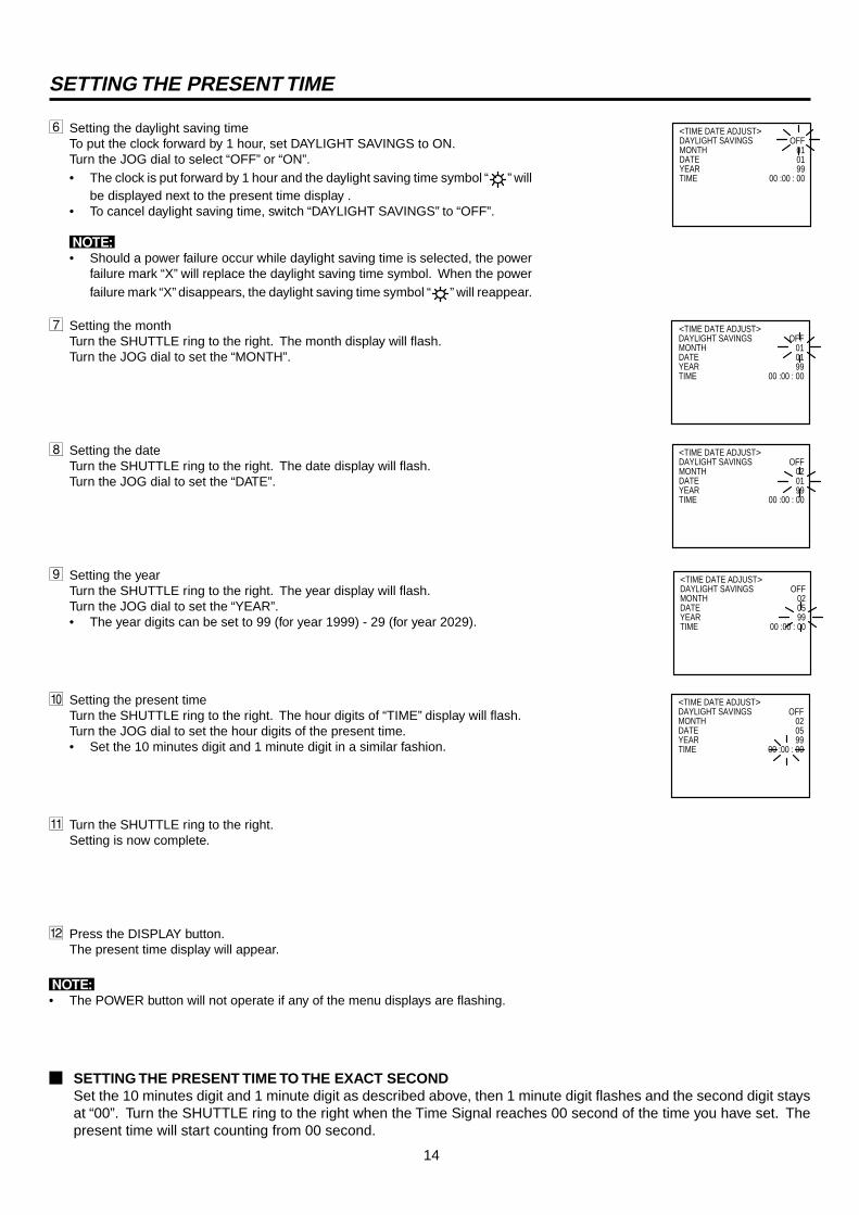
6 Setting the daylight saving timeTo put the clock forward by 1 hour, set DAYLIGHT SAVINGS to ON.Turn the JOG dial to select “OFF” or “ON”.• The clock is put forward by 1 hour and the daylight saving time symbol “ ” will
be displayed next to the present time display .• To cancel daylight saving time, switch “DAYLIGHT SAVINGS” to “OFF”.
N• Should a power failure occur while daylight saving time is selected, the power
failure mark “X” will replace the daylight saving time symbol. When the powerfailure mark “X” disappears, the daylight saving time symbol “ ” will reappear.
7 Setting the monthTurn the SHUTTLE ring to the right. The month display will flash.Turn the JOG dial to set the “MONTH”.
8 Setting the dateTurn the SHUTTLE ring to the right. The date display will flash.Turn the JOG dial to set the “DATE”.
9 Setting the yearTurn the SHUTTLE ring to the right. The year display will flash.Turn the JOG dial to set the “YEAR”.• The year digits can be set to 99 (for year 1999) - 29 (for year 2029).
A Setting the present timeTurn the SHUTTLE ring to the right. The hour digits of “TIME” display will flash.Turn the JOG dial to set the hour digits of the present time.• Set the 10 minutes digit and 1 minute digit in a similar fashion.
B Turn the SHUTTLE ring to the right.Setting is now complete.
C Press the DISPLAY button.The present time display will appear.
N• The POWER button will not operate if any of the menu displays are flashing.
2 SETTING THE PRESENT TIME TO THE EXACT SECONDSet the 10 minutes digit and 1 minute digit as described above, then 1 minute digit flashes and the second digit staysat “00”. Turn the SHUTTLE ring to the right when the Time Signal reaches 00 second of the time you have set. Thepresent time will start counting from 00 second.
OFF010199
00 :00 : 00
DAYLIGHT SAVINGSMONTHDATEYEARTIME
<TIME DATE ADJUST>
OFF010199
00 :00 : 00
DAYLIGHT SAVINGSMONTHDATEYEARTIME
<TIME DATE ADJUST>
OFF020199
00 :00 : 00
DAYLIGHT SAVINGSMONTHDATEYEARTIME
<TIME DATE ADJUST>
OFF020599
00 :00 : 00
DAYLIGHT SAVINGSMONTHDATEYEARTIME
<TIME DATE ADJUST>
OFF020599
00 :00 : 00
DAYLIGHT SAVINGSMONTHDATEYEARTIME
<TIME DATE ADJUST>
SETTING THE PRESENT TIME
15
ENTERFF
CLEARREW
JOG/ADJUST SHUTTLE/ENTER REC
STOP
PLAY
POWER
EJECT
PICTURE
TRACKINGPOSITION/VERTICALADJUST
REC/PLAY MODECOUNTER
RESET
COUNTER MEMORYSKIP/INDEX
PAUSE/SHUTTLE HOLD
DISPLAY
TIMER REC
VIDEO
SOFT SHARP
COLOR B/W
Video cassette tapes can be loaded into your new VCR as long as the VCR is plugged into a power source. Even if the VCR powerswitch is turned off, loading a cassette will automatically cause it to turn on. Use only video cassette tapes marked V V V V V or SSSSS.
Do not use a E-240 or SE-240 cassette tape when recording in 48H - 960H or 0H mode.
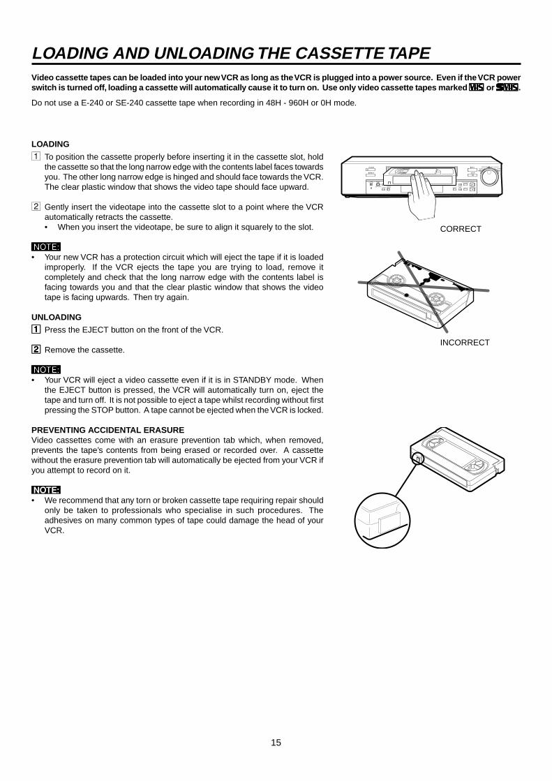
LOADING
1 To position the cassette properly before inserting it in the cassette slot, holdthe cassette so that the long narrow edge with the contents label faces towardsyou. The other long narrow edge is hinged and should face towards the VCR.The clear plastic window that shows the video tape should face upward.
2 Gently insert the videotape into the cassette slot to a point where the VCRautomatically retracts the cassette.• When you insert the videotape, be sure to align it squarely to the slot.
NNNNN• Your new VCR has a protection circuit which will eject the tape if it is loaded
improperly. If the VCR ejects the tape you are trying to load, remove itcompletely and check that the long narrow edge with the contents label isfacing towards you and that the clear plastic window that shows the videotape is facing upwards. Then try again.
UNLOADING
11111 Press the EJECT button on the front of the VCR.
22222 Remove the cassette.
NNNNN• Your VCR will eject a video cassette even if it is in STANDBY mode. When
the EJECT button is pressed, the VCR will automatically turn on, eject thetape and turn off. It is not possible to eject a tape whilst recording without firstpressing the STOP button. A tape cannot be ejected when the VCR is locked.
PREVENTING ACCIDENTAL ERASUREVideo cassettes come with an erasure prevention tab which, when removed,prevents the tape’s contents from being erased or recorded over. A cassettewithout the erasure prevention tab will automatically be ejected from your VCR ifyou attempt to record on it.
N• We recommend that any torn or broken cassette tape requiring repair should
only be taken to professionals who specialise in such procedures. Theadhesives on many common types of tape could damage the head of yourVCR.
LOADING AND UNLOADING THE CASSETTE TAPE
CORRECT
INCORRECT
16
REW FF
JOG/ADJUST
CLEAR/ ENTER/
SHUTTLEREC
STOP
PLAY
POWER
EJECT
PICTURE
TRACKINGPOSITION/VERTICALADJUST
REC/PLAYMODECOUNTER
RESET
COUNTER MEMORY/SKIP/INDEX
PAUSE/SHUTTLE HOLD
DISPLAY
TIMER REC
S-VHS
SOFT SHARP
OFF ON
LOCK button
MANUAL RECORDING
REC MODE 3H L12H L24H 48H 72H 96H 120H 168H 240H 360H 480H 720H 960HE-180
SE-180E-240
SE-240
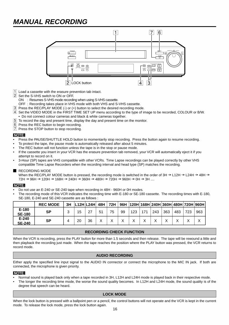
1 Load a cassette with the erasure prevention tab intact.2 Set the S-VHS switch to ON or OFF.
ON : Resumes S-VHS mode recording when using S-VHS cassette.OFF : Recording takes place in VHS mode with both VHS and S-VHS cassette.
3 Press the REC/PLAY MODE (-) or (+) button to select the desired recording mode.4 Set the VIDEO MODE in the FIRST TIME SET UP menu according to the type of image to be recorded, COLOUR or B/W.
• Do not connect colour cameras and black & white cameras together.5 To record the day and present time, display the day and present time on the monitor.6 Press the REC button to begin recording.7 Press the STOP button to stop recording.
N• Press the PAUSE/SHUTTLE HOLD button to momentarily stop recording. Press the button again to resume recording.• To protect the tape, the pause mode is automatically released after about 5 minutes.• The REC button will not function unless the tape is in the stop or pause mode.• If the cassette you insert in your VCR has the erasure prevention tab removed, your VCR will automatically eject it if you
attempt to record on it.• 3-Hour (SP) tapes are VHS compatible with other VCRs. Time Lapse recordings can be played correctly by other VHS
compatible Time Lapse Recorders when the recording interval and head type (SP) matches the recording.
2 RECORDING MODEWhen the REC/PLAY MODE button is pressed, the recording mode is switched in the order of 3H L12H L24H 48H 72H 96H 120H 168H 240H 360H 480H 720H 960H 0H 3H ....
N• Do not use an E-240 or SE-240 tape when recording in 48H - 960H or 0H modes.• The recording mode of this VCR indicates the recording time with E-180 or SE-180 cassette. The recording times with E-180,
SE-180, E-240 and SE-240 cassette are as follows :
RECORDING CHECK FUNCTION
When the VCR is recording, press the PLAY button for more than 1.5 seconds and then release. The tape will be rewound a little andthen playback the recording just made. When the tape reaches the position where the PLAY button was pressed, the VCR returns torecord mode.
AUDIO RECORDING
Either apply the specified line input signal to the AUDIO IN connector or connect the microphone to the MIC IN jack. If both areconnected, the microphone is given priority.
N• Normal sound is played back only when a tape recorded in 3H, L12H and L24H mode is played back in their respective mode.• The longer the recording time mode, the worse the sound quality becomes. In L12H and L24H mode, the sound quality is of the
degree that speech can be heard.
LOCK MODE
When the lock button is pressed with a ballpoint pen or a pencil, the control buttons will not operate and the VCR is kept in the currentmode. To release the lock mode, press the lock button again.
SP 4 20 36 X X X X X X X X X X
SP 3 15 27 51 75 99 123 171 243 363 483 723 963
1 7 6
2 4 3
17
Recording time mode
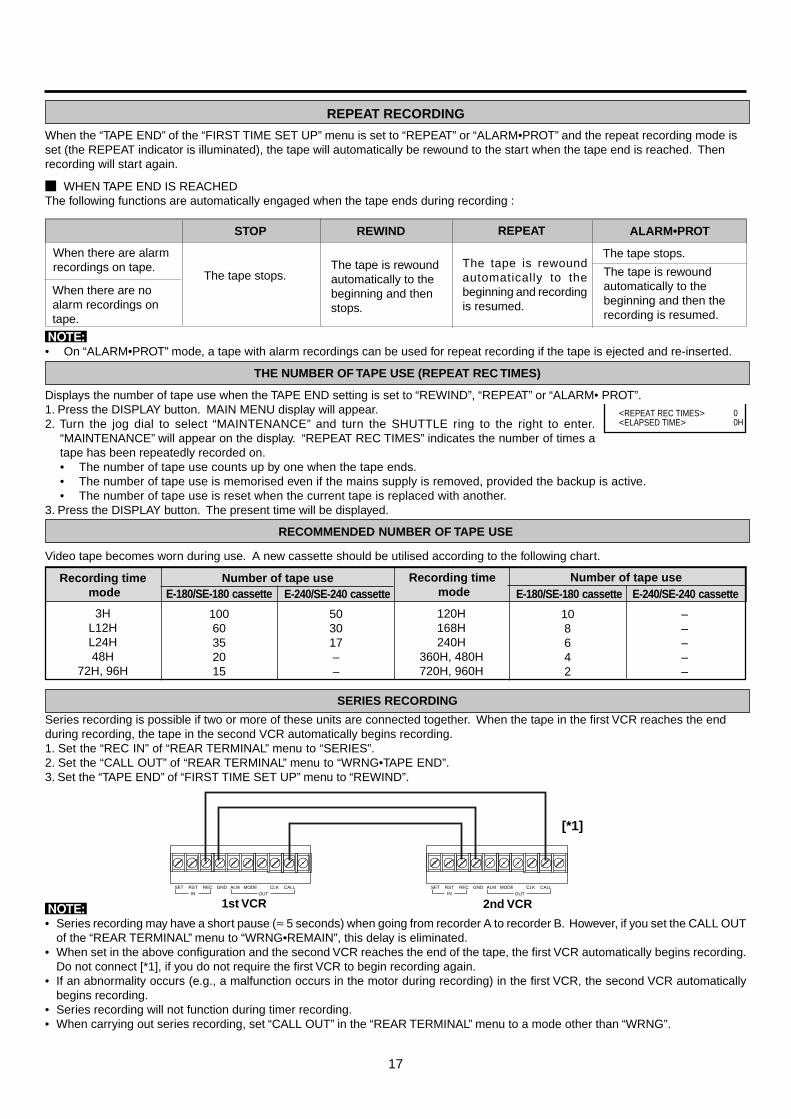
REPEAT RECORDING
When the “TAPE END” of the “FIRST TIME SET UP” menu is set to “REPEAT” or “ALARM•PROT” and the repeat recording mode isset (the REPEAT indicator is illuminated), the tape will automatically be rewound to the start when the tape end is reached. Thenrecording will start again.
2 WHEN TAPE END IS REACHEDThe following functions are automatically engaged when the tape ends during recording :
STOP REWIND REPEAT ALARM•PROT
The tape is rewoundautomatically to thebeginning and recordingis resumed.
The tape is rewoundautomatically to thebeginning and thenstops.
The tape stops.
When there are alarmrecordings on tape.
The tape stops.
The tape is rewoundautomatically to thebeginning and then therecording is resumed.
When there are noalarm recordings ontape.
RECOMMENDED NUMBER OF TAPE USE
Video tape becomes worn during use. A new cassette should be utilised according to the following chart.
Number of tape useE-180/SE-180 cassette E-240/SE-240 cassette
10060352015
503017––
3HL12HL24H48H
72H, 96H
N• On “ALARM•PROT” mode, a tape with alarm recordings can be used for repeat recording if the tape is ejected and re-inserted.
THE NUMBER OF TAPE USE (REPEAT REC TIMES)
Displays the number of tape use when the TAPE END setting is set to “REWIND”, “REPEAT” or “ALARM• PROT”.1. Press the DISPLAY button. MAIN MENU display will appear.2. Turn the jog dial to select “MAINTENANCE” and turn the SHUTTLE ring to the right to enter.
“MAINTENANCE” will appear on the display. “REPEAT REC TIMES” indicates the number of times atape has been repeatedly recorded on.• The number of tape use counts up by one when the tape ends.• The number of tape use is memorised even if the mains supply is removed, provided the backup is active.• The number of tape use is reset when the current tape is replaced with another.
3. Press the DISPLAY button. The present time will be displayed.
Recording time mode
Number of tape useE-180/SE-180 cassette E-240/SE-240 cassette
SET RSTIN
REC GND ALM MODE CLK CALLOUT
SET RSTIN
REC GND ALM MODE CLK CALLOUT
SERIES RECORDING
[*1]
Series recording is possible if two or more of these units are connected together. When the tape in the first VCR reaches the endduring recording, the tape in the second VCR automatically begins recording.1. Set the “REC IN” of “REAR TERMINAL” menu to “SERIES”.2. Set the “CALL OUT” of “REAR TERMINAL” menu to “WRNG•TAPE END”.3. Set the “TAPE END” of “FIRST TIME SET UP” menu to “REWIND”.
N• Series recording may have a short pause (≈ 5 seconds) when going from recorder A to recorder B. However, if you set the CALL OUT
of the “REAR TERMINAL” menu to “WRNG•REMAIN”, this delay is eliminated.• When set in the above configuration and the second VCR reaches the end of the tape, the first VCR automatically begins recording.
Do not connect [*1], if you do not require the first VCR to begin recording again.• If an abnormality occurs (e.g., a malfunction occurs in the motor during recording) in the first VCR, the second VCR automatically
begins recording.• Series recording will not function during timer recording.• When carrying out series recording, set “CALL OUT” in the “REAR TERMINAL” menu to a mode other than “WRNG”.
00H
<REPEAT REC TIMES><ELAPSED TIME>
108642
–––––
120H168H240H
360H, 480H720H, 960H
1st VCR 2nd VCR

18
SYNCHRONOUS RECORDING
CAMERA1 CAMERA2 CAMERA3 CAMERA4 CAMERA5 CAMERA1 CAMERA2 CAMERA3 CAMERA4 CAMERA5
REC
REC
REC
REC
REC
REC
REC
REC
REC
REC
If you have three VCRs, the video signal from three cameras can be recorded separately by connecting the switcher as shown below.
SWITCHER/ switching cameras
/ recording start signal
VCR 1 / recording
/ clock outVCR 2 / recording
/ clock outVCR 3 / recording
/ clock out
A number of camera images can be mixed together through a camera switcher and then recorded separately onto severalVCRs. A camera is assigned to each VCR with the VCR recording only the camera image it has been assigned. Thisallows recording without gaps.
V-SYNC
Recording mode VCR Camera
L12HL24H
59
Multiple of 5Multiple of 9
Set the “REC IN” of “REAR TERMINAL” menu to “SERIES” or “REC-START/STOP” on VCR1.Set the “CLOCK OUT” of “REAR TERMINAL” menu to “T/L-REC” and “F” on VCR1.Set the “REC IN” of “REAR TERMINAL” menu to “SYNC REC” on all VCRs except VCR1.• If recording start signal is available on switcher, set the “REC IN” of the “REAR TERMINAL” menu to “SYNC REC” on
VCR1. Then, VCR1 will always record the picture from CAMERA1.
• You must set the recording mode to L12H or L24H mode.• The suitable numbers of VCRs and cameras are shown in the table.
ONE SHOT/INTERVAL RECORDING
One-shot recording or Interval recording is possible when the recording mode is set to 0H.
1 Press the REC/PLAY MODE button to set the recording mode to 0H.2 Set the number of fields in “ONE SHOT•FIELD” on the “RECORDING SET UP” menu.3 For One-shot recording, select “SHOT” in “ONE SHOT•INTERVAL”.
For Interval recording, choose the interval time from 10S(second) to 3M(minute) in “ONE SHOT•INTERVAL”.4 Press the REC button.
• One-shot recording will be on STANDBY mode. Interval recording begins recording with the preset interval time.5 To start One-shot recording, press the REC button or switch the REC IN terminal on the rear panel to ground.
REW FF
JOG/ADJUST
CLEAR/ ENTER/
SHUTTLEREC
STOP
PLAY
POWER
EJECT
PICTURE
TRACKINGPOSITION/VERTICALADJUST
REC/PLAY MODECOUNTER
RESET
COUNTER MEMORY/SKIP/INDEX
PAUSE/SHUTTLE HOLD
DISPLAY
TIMER REC
VIDEO
SOFT SHARP
COLOR B/W
REW FF
JOG/ADJUST
CLEAR/ ENTER/
SHUTTLEREC
STOP
PLAY
POWER
EJECT
PICTURE
TRACKINGPOSITION/VERTICALADJUST
REC/PLAY MODECOUNTER
RESET
COUNTER MEMORY/SKIP/INDEX
PAUSE/SHUTTLE HOLD
DISPLAY
TIMER REC
VIDEO
SOFT SHARP
COLOR B/W
REW FF
JOG/ADJUST
CLEAR/ ENTER/
SHUTTLEREC
STOP
PLAY
POWER
EJECT
PICTURE
TRACKINGPOSITION/VERTICALADJUST
REC/PLAY MODECOUNTER
RESET
COUNTER MEMORY/SKIP/INDEX
PAUSE/SHUTTLE HOLD
DISPLAY
TIMER REC
VIDEO
SOFT SHARP
COLOR B/W
POWER
REW FF
JOG/ADJUST
CLEAR/ ENTER/
SHUTTLEREC
STOP
PLAY
POWER
EJECT
PICTURE
TRACKINGPOSITION/VERTICALADJUST
REC/PLAY MODECOUNTER
RESET
COUNTER MEMORY/SKIP/INDEX
PAUSE/SHUTTLE HOLD
DISPLAY
TIMER REC
VIDEO
SOFT SHARP
COLOR B/W
REW FF
JOG/ADJUST
CLEAR/ ENTER/
SHUTTLEREC
STOP
PLAY
POWER
EJECT
PICTURE
TRACKINGPOSITION/VERTICALADJUST
REC/PLAY MODECOUNTER
RESET
COUNTER MEMORY/SKIP/INDEX
PAUSE/SHUTTLE HOLD
DISPLAY
TIMER REC
VIDEO
SOFT SHARP
COLOR B/W
Connection: VIDEO INCLK OUT
CAMERAS
VCR1
VCR2SWITCHER CLK OUT
REC IN
REC INVCR3
CAMERA 1
CAMERA 2
CAMERA 3
CAMERA 4
CAMERA 5
VCR5
VCR4
CLK OUT
CLK OUTREC IN
REC IN
VCR 4 / recording
/ clock out
VCR 5 / recording / clock out
MANUAL RECORDING

19
TAPE COUNTER
A five digit counter indicates the relative position on the recorded portion of the tape. If a portion of thetape is not recorded, the counter will not increase or decrease during play, FF/RWD or search modes.
• “EEE EE” illuminates to indicate that the VCR power is in stand-by mode.
COUNTER MEMORY
Press the COUNTER MEMORY/SKIP/INDEX button repeatedly until the “M” indicator appears on the fluorescent display.Turn the SHUTTLE ring to the right and the tape will rewind to the “00000” position of the counter and stop. (The rewind to “00000” isslightly inaccurate.)N• The counter display is stored in the memory when the power is turned off, so the same numbers will be displayed when the
power is turned back on.
ADDITIONAL FEATURES
COUNTER RESET
MEMORY BACK-UP IN CASE OF POWER FAILURE
This VCR includes a built-in memory back-up so the presets of present time and date, alarm list, power loss list and the number oftape use will remain in memory if there is a power failure or if the POWER CORD is disconnected from the mains outlet. The presetswill remain in memory for a maximum of 31days provided that the VCR has been connected to the mains supply for at least 40 hoursper week. Connection charges the backup supply.• Check the present time if there has been a power failure or if the POWER CORD has been disconnected from the mains for a
prolonged time.
If there is a power failure during recording and the power comes back on, the VCR will beginrecording in the same record mode as before the power failure. After the power comes back on,“X” will be displayed next to the present time for about 1 minute.If a power failure occurs during playback, the VCR will be in the stop mode when the powercomes back on.
RECORDING AFTER A POWER FAILURE
The power failure start time on recording is stored in the memory, so it is possible to confirm the start time.1. Press the DISPLAY button to display the MAIN MENU.2. Turn the JOG dial to select “MAINTENANCE” and turn the SHUTTLE ring to the right.
“MAINTENANCE” display will appear.3. Turn the JOG dial to select “POWER LOSS LIST” and turn the SHUTTLE ring to the right.
“POWER LOSS LIST” will appear.• Up to 3 power failure start times will be displayed. If more than 3 failures have occurred, the first and the last 2 power failure start
times will be displayed.• To reset the “POWER LOSS LIST”, select the “POWER LOSS LIST CLEAR” in the “MAINTENANCE” setting display and turn the
SHUTTLE ring to the right. The initialize menu will appear and turn the SHUTTLE ring to the left.
ELAPSED TIME DISPLAY
The elapsed time of recording and playback are stored in memory. The elapsed time should be used as a guide for periodicreplacement of parts.
1. Press the DISPLAY button to display the MAIN MENU.2. Turn the JOG dial to select “MAINTENANCE” and turn the SHUTTLE ring to the right.
“ELAPSED TIME” is indicated.• The elapsed time counts up to 89,999 hours.
3. Press the DISPLAY button.• The present time display will appear.
POWER FAILURE TIME DISPLAY
01-01-99 FRI
00:00:00X L12
<POWER LOSS LIST>01 03 - 01 - 99 01 : 000203
00H
<REPEAT REC TIMES><ELAPSED TIME>
Press the COUNTER RESET button to reset the counter to “00000”.
20
)
DW START END HR1 SPL 08 : 40 17 : 10 L12SP
- - - - - : - - - - : - - - - -
)
DW START END HR1 SPL 08 : 40 17 : 10 L12SP
SAT - - : - - - - : - - - - -
)
DW START END HR1 SPL 08 : 40 17 : 10 L12SP
SAT - - : - - - - : - - - - -
)
DW START END HR1 SPL 08 : 40 17 : 10 L12SP
SAT 08 : 00 - - : - - - - -
)
DW START END HR1 SPL 08 : 40 17 : 10 L12SP
SAT 08 : 00 - - : - - - - -
)
DW START END HR1 SPL 08 : 40 17 : 10 L12SP
SAT 08 : 00 12 : 00 - - -
)
DW START END HR1 SPL 08 : 40 17 : 10 L12SP
SAT 08 : 00 12 : 00 - - -
)
DW START END HR1 SPL 08 : 40 17 : 10 L12SP
SAT 08 : 00 12 : 00 72SP
<TIMER PROGRAM >)
DW START END HRSPL 08 : 40 17 : 10 L12SP
2 - - - - - : - - - - : - - - - -
TIMER RECORDING
<MAIN MENU> DISPLAY TIME DATE SEARCH TIMER PROGRAM RECORDING SET UP REAR TERMINAL MAINTENANCE FIRST TIME SET UPUse JOG to select, and ENTER.Press DISPLAY to exit.
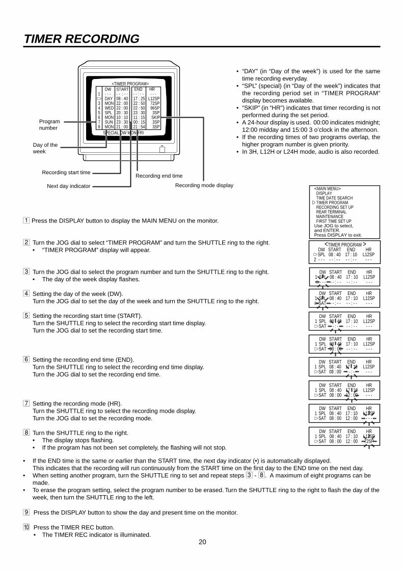
• “DAY” (in “Day of the week”) is used for the sametime recording everyday.
• “SPL” (special) (in “Day of the week”) indicates thatthe recording period set in “TIMER PROGRAM”display becomes available.
• “SKIP” (in “HR”) indicates that timer recording is notperformed during the set period.
• A 24-hour display is used. 00:00 indicates midnight;12:00 midday and 15:00 3 o’clock in the afternoon.
• If the recording times of two programs overlap, thehigher program number is given priority.
• In 3H, L12H or L24H mode, audio is also recorded.
1 Press the DISPLAY button to display the MAIN MENU on the monitor.
2 Turn the JOG dial to select “TIMER PROGRAM” and turn the SHUTTLE ring to the right.• “TIMER PROGRAM” display will appear.
3 Turn the JOG dial to select the program number and turn the SHUTTLE ring to the right.• The day of the week display flashes.
4 Setting the day of the week (DW).Turn the JOG dial to set the day of the week and turn the SHUTTLE ring to the right.
5 Setting the recording start time (START).Turn the SHUTTLE ring to select the recording start time display.Turn the JOG dial to set the recording start time.
6 Setting the recording end time (END).Turn the SHUTTLE ring to select the recording end time display.Turn the JOG dial to set the recording end time.
7 Setting the recording mode (HR).Turn the SHUTTLE ring to select the recording mode display.Turn the JOG dial to set the recording mode.
8 Turn the SHUTTLE ring to the right.• The display stops flashing.• If the program has not been set completely, the flashing will not stop.
• If the END time is the same or earlier than the START time, the next day indicator (•) is automatically displayed.This indicates that the recording will run continuously from the START time on the first day to the END time on the next day.
• When setting another program, turn the SHUTTLE ring to set and repeat steps 3 - 8. A maximum of eight programs can bemade.
• To erase the program setting, select the program number to be erased. Turn the SHUTTLE ring to the right to flash the day of theweek, then turn the SHUTTLE ring to the left.
9 Press the DISPLAY button to show the day and present time on the monitor.
A Press the TIMER REC button.• The TIMER REC indicator is illuminated.
<TIMER PROGRAM>DW START END HR
1 - - - - - : - - - - : - - - - -2 DAY 08 : 40 17 : 25 L12SP3 MON 22 : 00 22 : 50 72SP4 WED 22 : 00 22 : 50 96SP5 SPL 20 : 30 23 : 30 3SP6 MON 10 : 10 11 : 15 SKIP7 SUN 23 : 30 00 : 15 3SP8 MON 21 : 00 21 : 54 3SP
SPECIAL DW MON-FRI
Programnumber
Day of theweek
Recording start time
Next day indicator
Recording end time
Recording mode display
)
21
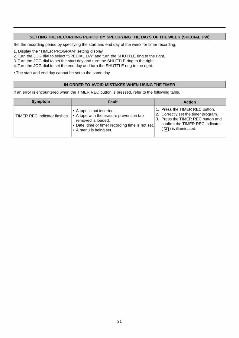
SETTING THE RECORDING PERIOD BY SPECIFYING THE DAYS OF THE WEEK (SPECIAL DW)
Set the recording period by specifying the start and end day of the week for timer recording.
1. Display the “TIMER PROGRAM” setting display.2. Turn the JOG dial to select “SPECIAL DW” and turn the SHUTTLE ring to the right.3. Turn the JOG dial to set the start day and turn the SHUTTLE ring to the right.4. Turn the JOG dial to set the end day and turn the SHUTTLE ring to the right.
• The start and end day cannot be set to the same day.
IN ORDER TO AVOID MISTAKES WHEN USING THE TIMER
If an error is encountered when the TIMER REC button is pressed, refer to the following table.
TIMER REC indicator flashes.
Symptom
1. Press the TIMER REC button.2. Correctly set the timer program.3. Press the TIMER REC button and
confirm the TIMER REC indicator( ) is illuminated.
Fault Action
• A tape is not inserted.• A tape with the erasure prevention tab
removed is loaded.• Date, time or timer recording time is not set.• A menu is being set.
22
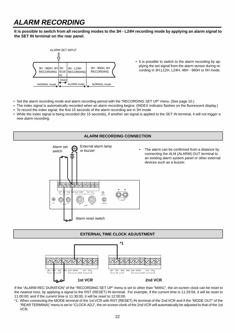
ALARM RECORDING
• It is possible to switch to the alarm recording by ap-plying the set signal from the alarm sensor during re-cording in 3H,L12H, L24H, 48H - 960H or 0H mode.
• Set the alarm recording mode and alarm recording period with the “RECORDING SET UP” menu. (See page 10.)• The index signal is automatically recorded when an alarm recording begins. (INDEX indicator flashes on the fluorescent display.)• To record the index signal, the first 15 seconds of the alarm recording are in 3H mode.• While the index signal is being recorded (for 15 seconds), if another set signal is applied to the SET IN terminal, it will not trigger a
new alarm recording.
ALARM RECORDING CONNECTION
External alarm lampor buzzer
Alarm reset switch
• The alarm can be confirmed from a distance byconnecting the ALM (ALARM) OUT terminal toan existing alarm system panel or other externaldevices such as a buzzer.
EXTERNAL TIME CLOCK ADJUSTMENT
If the “ALARM REC DURATION” of the “RECORDING SET UP” menu is set to other than “MAN1”, the on-screen clock can be reset tothe nearest hour, by applying a signal to the RST (RESET) IN terminal. For example, if the current time is 11:29:59, it will be reset to11:00:00; and if the current time is 11:30:00, it will be reset to 12:00:00.*1: When connecting the MODE terminal of the 1st VCR with RST (RESET) IN terminal of the 2nd VCR and if the “MODE OUT” of the
“REAR TERMINAL” menu is set to “CLOCK ADJ”, the on-screen clock of the 2nd VCR will automatically be adjusted to that of the 1stVCR.
Alarm setswitch
It is possible to switch from all recording modes to the 3H - L24H recording mode by applying an alarm signal tothe SET IN terminal on the rear panel.
ALARM SET INPUT
3H - 960H, 0HRECORDING
3H - 960H, 0HRECORDING
3HRECORD-ING
3H - L24HRECORDING
15sec
NORMAL mode NORMAL modeALARM mode
VIDEOOUTIN
IN OUTMICAUDIO
RESET
REMOTE
SET RSTIN
REC GND ALM MODE CLK CALLOUT
IN OUTS-VIDEO
SET RSTIN
REC GND ALM MODE CLK CALLOUT
SET RSTIN
REC GND ALM MODE CLK CALLOUT
1st VCR 2nd VCR
*1
23
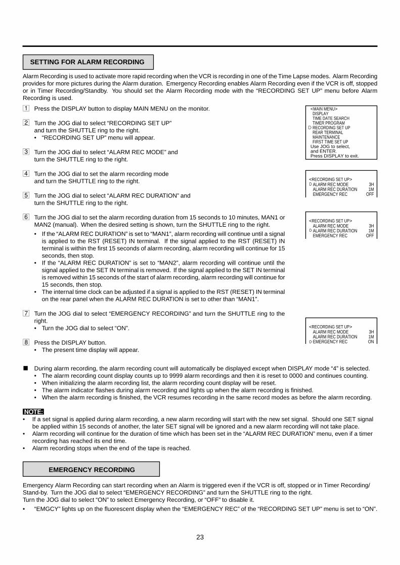
SETTING FOR ALARM RECORDING
1 Press the DISPLAY button to display MAIN MENU on the monitor.
2 Turn the JOG dial to select “RECORDING SET UP”and turn the SHUTTLE ring to the right.• “RECORDING SET UP” menu will appear.
3 Turn the JOG dial to select “ALARM REC MODE” andturn the SHUTTLE ring to the right.
4 Turn the JOG dial to set the alarm recording modeand turn the SHUTTLE ring to the right.
5 Turn the JOG dial to select “ALARM REC DURATION” andturn the SHUTTLE ring to the right.
6 Turn the JOG dial to set the alarm recording duration from 15 seconds to 10 minutes, MAN1 orMAN2 (manual). When the desired setting is shown, turn the SHUTTLE ring to the right.
• If the “ALARM REC DURATION” is set to “MAN1”, alarm recording will continue until a signalis applied to the RST (RESET) IN terminal. If the signal applied to the RST (RESET) INterminal is within the first 15 seconds of alarm recording, alarm recording will continue for 15seconds, then stop.
• If the “ALARM REC DURATION” is set to “MAN2”, alarm recording will continue until thesignal applied to the SET IN terminal is removed. If the signal applied to the SET IN terminalis removed within 15 seconds of the start of alarm recording, alarm recording will continue for15 seconds, then stop.
• The internal time clock can be adjusted if a signal is applied to the RST (RESET) IN terminalon the rear panel when the ALARM REC DURATION is set to other than “MAN1”.
7 Turn the JOG dial to select “EMERGENCY RECORDING” and turn the SHUTTLE ring to theright.• Turn the JOG dial to select “ON”.
8 Press the DISPLAY button.• The present time display will appear.
^ During alarm recording, the alarm recording count will automatically be displayed except when DISPLAY mode “4” is selected.• The alarm recording count display counts up to 9999 alarm recordings and then it is reset to 0000 and continues counting.• When initializing the alarm recording list, the alarm recording count display will be reset.• The alarm indicator flashes during alarm recording and lights up when the alarm recording is finished.• When the alarm recording is finished, the VCR resumes recording in the same record modes as before the alarm recording.
N• If a set signal is applied during alarm recording, a new alarm recording will start with the new set signal. Should one SET signal
be applied within 15 seconds of another, the later SET signal will be ignored and a new alarm recording will not take place.• Alarm recording will continue for the duration of time which has been set in the “ALARM REC DURATION” menu, even if a timer
recording has reached its end time.• Alarm recording stops when the end of the tape is reached.
EMERGENCY RECORDING
Emergency Alarm Recording can start recording when an Alarm is triggered even if the VCR is off, stopped or in Timer Recording/Stand-by. Turn the JOG dial to select “EMERGENCY RECORDING” and turn the SHUTTLE ring to the right.Turn the JOG dial to select “ON” to select Emergency Recording, or “OFF” to disable it.
• “EMGCY” lights up on the fluorescent display when the “EMERGENCY REC” of the “RECORDING SET UP” menu is set to “ON”.
<MAIN MENU> DISPLAY TIME DATE SEARCH TIMER PROGRAM RECORDING SET UP REAR TERMINAL MAINTENANCE FIRST TIME SET UPUse JOG to select, and ENTER.Press DISPLAY to exit.
<RECORDING SET UP>3H1M
OFF
ALARM REC MODEALARM REC DURATIONEMERGENCY REC
<RECORDING SET UP>3H1M
OFF
ALARM REC MODEALARM REC DURATIONEMERGENCY REC
<RECORDING SET UP>3H1MON
ALARM REC MODEALARM REC DURATIONEMERGENCY REC
Alarm Recording is used to activate more rapid recording when the VCR is recording in one of the Time Lapse modes. Alarm Recordingprovides for more pictures during the Alarm duration. Emergency Recording enables Alarm Recording even if the VCR is off, stoppedor in Timer Recording/Standby. You should set the Alarm Recording mode with the “RECORDING SET UP” menu before AlarmRecording is used.

24
LOCATING THE START OF ALARM RECORDINGS
This machine automatically inserts an index signal at the beginning of each ALARM RECORDING, allowing the start of each alarmto be located.
^ INDEX SEARCHDuring fast forward or rewind the machine will search for index signals. When an Index signal is found, the VCR will playback thetape and stay in still mode.
1 Press the COUNTER MEMORY/SKIP/INDEX button to illuminate “INDEX” on the fluorescent display.(On the fluorescent display “INDEX” will be illuminated and the number indication will be illuminated.)
2 Turn the JOG dial to display the number (1-15) corresponding to the alarm index you desire to locate.3 Turn the SHUTTLE ring to the right (forward direction) or left (reverse direction).
(The program indication number will decrease one by one as each index signal goes by.)
• The index signal may be difficult to locate in some recording conditions.
^ SKIP SEARCHThe VCR will fast forward or rewind until an index signal is located and then playback for about 4 seconds in 3H mode. This processis repeated until the end or beginning of the tape is reached.
-15 -1 +1 +2 +15
ALARMRECORDING
ALARMRECORD-ING
ALARMRECORDING
ALARMRECORDING
ALARMRECORDING
Present position
Rewind direction Fast forward direction
1 Press the COUNTER MEMORY/SKIP/INDEX button to illuminate“SKIP” on the fluorescent display.
2 Turn the SHUTTLE ring to the right or left.
ALARMRECORDING
ALARMRECORDING
Present position
Index
Fast forwardFast forward
Index
Approx. 4 sec.playback
Approx. 4 sec.playback
Fast forward
Until the index signal is located, the machine will fast forward (or rewind). When an index signal is located, the machine will playback(in 3H mode) for about 4 seconds. This process will be repeated until the end or the beginning of the tape is reached.• When the desired position is located, press the PLAY button.• To stop SKIP SEARCH, press the STOP button.• The index signal may be difficult to locate in some recording conditions.
ALARM RECORD TIME DISPLAY
When alarm recordings begin, the start times are stored in memory, so it is possible to confirm when theyhave occurred. Select the “ALARM LIST” in the “MAINTENANCE” menu and the alarm list display willappear on the screen.• Up to 3 alarm recording start times can be stored in memory. For more than that, the first and the last 2
times will be displayed.• The alarm recording list is reset by the following procedure.
1. Select the “ALARM LIST CLEAR” in the “MAINTENANCE” menu.2. Turn the SHUTTLE ring to the right. “ALARM LIST CLEAR” will be displayed.3. Turn the SHUTTLE ring to the left. “ALARM LIST” will be cleared.
<ALARM LIST>0001 05 - 01 - 99 01 : 000002 07 - 01 - 99 21 : 100003 10 - 01 - 99 09 : 15
ALARM RECORDING
25
REW FF
JOG/ADJUST
CLEAR/ ENTER/
SHUTTLEREC
STOP
PLAY
POWER
EJECT
PICTURE
TRACKINGPOSITION/VERTICALADJUST
REC/PLAY MODECOUNTER
RESET
COUNTER MEMORY/SKIP/INDEX
PAUAESHUTTLE HOLD
DISPLAY
TIMER REC
S-VHS
SOFT SHARP
OFF ON
5
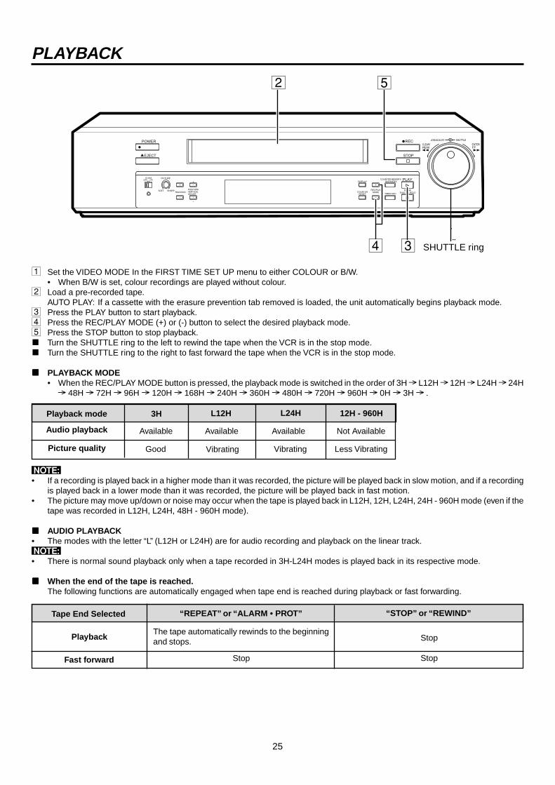
1 Set the VIDEO MODE In the FIRST TIME SET UP menu to either COLOUR or B/W.• When B/W is set, colour recordings are played without colour.
2 Load a pre-recorded tape.AUTO PLAY: If a cassette with the erasure prevention tab removed is loaded, the unit automatically begins playback mode.
3 Press the PLAY button to start playback.4 Press the REC/PLAY MODE (+) or (-) button to select the desired playback mode.5 Press the STOP button to stop playback.^ Turn the SHUTTLE ring to the left to rewind the tape when the VCR is in the stop mode.^ Turn the SHUTTLE ring to the right to fast forward the tape when the VCR is in the stop mode.
^ PLAYBACK MODE• When the REC/PLAY MODE button is pressed, the playback mode is switched in the order of 3H L12H 12H L24H 24H
48H 72H 96H 120H 168H 240H 360H 480H 720H 960H 0H 3H .
2
4 3
PLAYBACK
Tape End Selected “REPEAT” or “ALARM • PROT”
PlaybackThe tape automatically rewinds to the beginningand stops. Stop
“STOP” or “REWIND”
Fast forward Stop Stop
Playback mode 3H
Audio playback Available
Picture quality Good
L12H
Available
Vibrating
L24H 12H - 960H
Not Available
Less Vibrating
N• If a recording is played back in a higher mode than it was recorded, the picture will be played back in slow motion, and if a recording
is played back in a lower mode than it was recorded, the picture will be played back in fast motion.• The picture may move up/down or noise may occur when the tape is played back in L12H, 12H, L24H, 24H - 960H mode (even if the
tape was recorded in L12H, L24H, 48H - 960H mode).
^ AUDIO PLAYBACK• The modes with the letter “L” (L12H or L24H) are for audio recording and playback on the linear track.N• There is normal sound playback only when a tape recorded in 3H-L24H modes is played back in its respective mode.
^ When the end of the tape is reached.The following functions are automatically engaged when tape end is reached during playback or fast forwarding.
Available
Vibrating
SHUTTLE ring
26
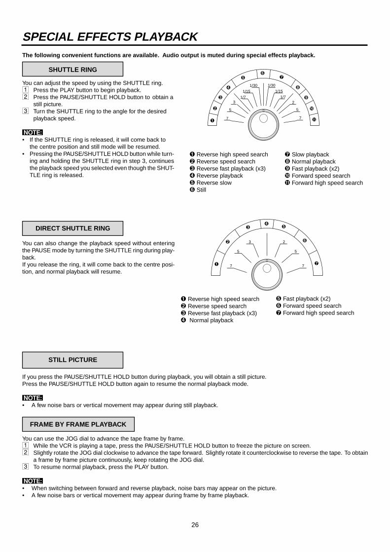
SPECIAL EFFECTS PLAYBACKThe following convenient functions are available. Audio output is muted during special effects playback.
SHUTTLE RING
You can adjust the speed by using the SHUTTLE ring.1 Press the PLAY button to begin playback.2 Press the PAUSE/SHUTTLE HOLD button to obtain a
still picture.3 Turn the SHUTTLE ring to the angle for the desired
playback speed.
N• If the SHUTTLE ring is released, it will come back to
the centre position and still mode will be resumed.• Pressing the PAUSE/SHUTTLE HOLD button while turn-
ing and holding the SHUTTLE ring in step 3, continuesthe playback speed you selected even though the SHUT-TLE ring is released.
STILL PICTURE
If you press the PAUSE/SHUTTLE HOLD button during playback, you will obtain a still picture.Press the PAUSE/SHUTTLE HOLD button again to resume the normal playback mode.
N• A few noise bars or vertical movement may appear during still playback.
FRAME BY FRAME PLAYBACK
You can use the JOG dial to advance the tape frame by frame.1 While the VCR is playing a tape, press the PAUSE/SHUTTLE HOLD button to freeze the picture on screen.2 Slightly rotate the JOG dial clockwise to advance the tape forward. Slightly rotate it counterclockwise to reverse the tape. To obtain
a frame by frame picture continuously, keep rotating the JOG dial.3 To resume normal playback, press the PLAY button.
N• When switching between forward and reverse playback, noise bars may appear on the picture.• A few noise bars or vertical movement may appear during frame by frame playback.
You can also change the playback speed without enteringthe PAUSE mode by turning the SHUTTLE ring during play-back.If you release the ring, it will come back to the centre posi-tion, and normal playback will resume.
1 Reverse high speed search2 Reverse speed search3 Reverse fast playback (x3)4 Reverse playback5 Reverse slow6 Still
7
5
21/7
1/15
1/301/30
1/15
1/7
5
7
3
1
2
3
4
56
7
8
9
A
B
7 Slow playback8 Normal playback9 Fast playback (x2)A Forward speed searchB Forward high speed search
1 Reverse high speed search2 Reverse speed search3 Reverse fast playback (x3)4 Normal playback
5 Fast playback (x2)6 Forward speed search7 Forward high speed search
3
5
7
2
5
71
2
34
5
6
7
DIRECT SHUTTLE RING
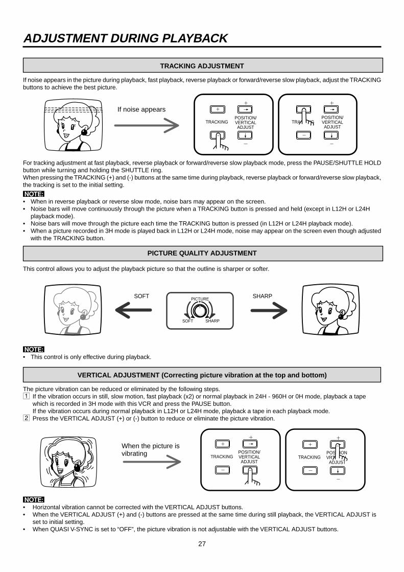
27
PICTURESOFT SHARP
SOFT SHARP
ADJUSTMENT DURING PLAYBACK
If noise appears in the picture during playback, fast playback, reverse playback or forward/reverse slow playback, adjust the TRACKINGbuttons to achieve the best picture.
If noise appears
TRACKINGPOSITION/VERTICALADJUST
TRACKINGPOSITION/VERTICAL ADJUST
TRACKING ADJUSTMENT
When the picture isvibrating TRACKING
POSITION/VERTICALADJUST
TRACKINGPOSITIONVRTTICAL ADJUST
PICTURE QUALITY ADJUSTMENT
For tracking adjustment at fast playback, reverse playback or forward/reverse slow playback mode, press the PAUSE/SHUTTLE HOLDbutton while turning and holding the SHUTTLE ring.When pressing the TRACKING (+) and (-) buttons at the same time during playback, reverse playback or forward/reverse slow playback,the tracking is set to the initial setting.
N• When in reverse playback or reverse slow mode, noise bars may appear on the screen.• Noise bars will move continuously through the picture when a TRACKING button is pressed and held (except in L12H or L24H
playback mode).• Noise bars will move through the picture each time the TRACKING button is pressed (in L12H or L24H playback mode).• When a picture recorded in 3H mode is played back in L12H or L24H mode, noise may appear on the screen even though adjusted
with the TRACKING button.
This control allows you to adjust the playback picture so that the outline is sharper or softer.
N• This control is only effective during playback.
VERTICAL ADJUSTMENT (Correcting picture vibration at the top and bottom)
The picture vibration can be reduced or eliminated by the following steps.1 If the vibration occurs in still, slow motion, fast playback (x2) or normal playback in 24H - 960H or 0H mode, playback a tape
which is recorded in 3H mode with this VCR and press the PAUSE button.If the vibration occurs during normal playback in L12H or L24H mode, playback a tape in each playback mode.
2 Press the VERTICAL ADJUST (+) or (-) button to reduce or eliminate the picture vibration.
N• Horizontal vibration cannot be corrected with the VERTICAL ADJUST buttons.• When the VERTICAL ADJUST (+) and (-) buttons are pressed at the same time during still playback, the VERTICAL ADJUST is
set to initial setting.• When QUASI V-SYNC is set to “OFF”, the picture vibration is not adjustable with the VERTICAL ADJUST buttons.

28
NNNNN Before connecting the hardware, unplug the power cord of the VCR from the walloutlet, and turn the personal computer power off.
1 Connecting the VCR to a personal computer.
USING WITH THE PERSONAL COMPUTER
Personal computer
To RS-232CIN terminal
RS-232C cross cable
To RS-232C terminal
OUT
INRS-232C
VIDEOOUTIN
IN OUTAUDIO
RESET
SET RSTIN
REC GND ALM MODE CLK CALLOUT
ÉMIC REMOTE
IN OUTS-VIDEO
Personal computer
To RS-232C IN terminal
To RS-232C OUT terminal
To RS-232C IN terminal
To RS-232C IN terminal
To RS-232C OUT terminal
RS-232C cross cable
RS-232C cross cable
RS-232C cross cable
To RS-232C terminal
To RS-232C IN terminal
To RS-232C OUT terminal
RS-232C cross cable
1st VCR
2nd VCR
16th VCR
OUT
INRS-232C
OUT
INRS-232C
OUT
INRS-232C
a. Connect the RS-232C cross cable to the RS-232C terminal of the personal computer.
b. Connect the other end of cable to RS-232C INterminal on the VCR.
NNNNN• Refer to page 30 for the RS-232C cable
configuration.
2 Connecting multiple VCRs to a personal computer.Up to 16 VCRs may be controlled either individually or as a group. To dothis, connect the VCRs in series through the RS-232C IN and OUTconnectors of the interface board.
a. Connect the RS-232C cross cable to the RS-232C terminal on the personal computer.
b. Connect the other end of the cable to the RS-232C IN terminal to the 1st VCR.
c. Connect the end of the RS-232C cross cableto the RS-232C OUT terminal of the 1st VCRand the other end to the RS-232C IN terminalof the 2nd VCR.
d. Continue this process until the last (up to 16)VCR is connected.
NNNNN• RS-232C OUT terminal should be connected
to a time lapse VCR with RS-232C interfaceboard. This terminal can not be used toconnect to other general equipment with RS-232C connector.
CONFIGURING THE TIME LAPSE VCR
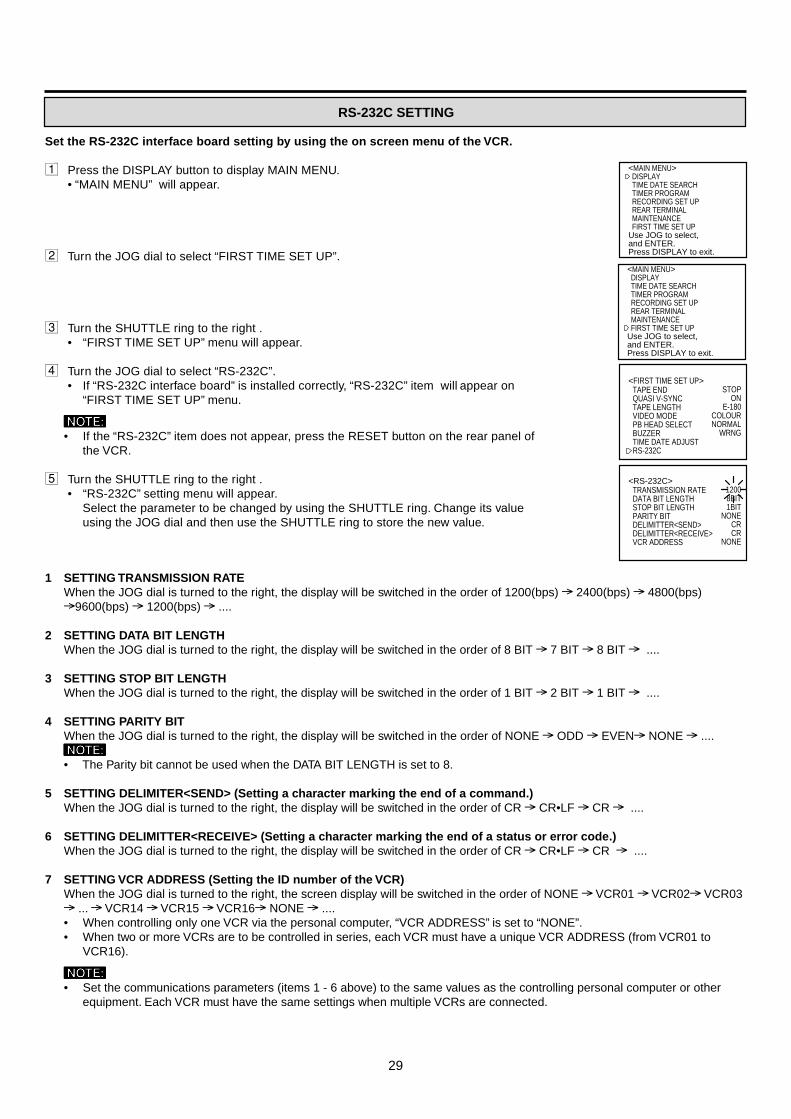
29
Set the RS-232C interface board setting by using the on screen menu of the VCR.
1 Press the DISPLAY button to display MAIN MENU.• “MAIN MENU” will appear.
2 Turn the JOG dial to select “FIRST TIME SET UP”.
3 Turn the SHUTTLE ring to the right .• “FIRST TIME SET UP” menu will appear.
4 Turn the JOG dial to select “RS-232C”.• If “RS-232C interface board” is installed correctly, “RS-232C” item will appear on
“FIRST TIME SET UP” menu.
NNNNN• If the “RS-232C” item does not appear, press the RESET button on the rear panel of
the VCR.
5 Turn the SHUTTLE ring to the right .• “RS-232C” setting menu will appear.
Select the parameter to be changed by using the SHUTTLE ring. Change its valueusing the JOG dial and then use the SHUTTLE ring to store the new value.
1 SETTING TRANSMISSION RATEWhen the JOG dial is turned to the right, the display will be switched in the order of 1200(bps) 2400(bps) 4800(bps)9600(bps) 1200(bps) ....
2 SETTING DATA BIT LENGTHWhen the JOG dial is turned to the right, the display will be switched in the order of 8 BIT 7 BIT 8 BIT ....
3 SETTING STOP BIT LENGTHWhen the JOG dial is turned to the right, the display will be switched in the order of 1 BIT 2 BIT 1 BIT ....
4 SETTING PARITY BITWhen the JOG dial is turned to the right, the display will be switched in the order of NONE ODD EVEN NONE ....NNNNN• The Parity bit cannot be used when the DATA BIT LENGTH is set to 8.
5 SETTING DELIMITER<SEND> (Setting a character marking the end of a command.)When the JOG dial is turned to the right, the display will be switched in the order of CR CR•LF CR ....
6 SETTING DELIMITTER<RECEIVE> (Setting a character marking the end of a status or error code.)When the JOG dial is turned to the right, the display will be switched in the order of CR CR•LF CR ....
7 SETTING VCR ADDRESS (Setting the ID number of the VCR)When the JOG dial is turned to the right, the screen display will be switched in the order of NONE VCR01 VCR02 VCR03 ... VCR14 VCR15 VCR16 NONE ....• When controlling only one VCR via the personal computer, “VCR ADDRESS” is set to “NONE”.• When two or more VCRs are to be controlled in series, each VCR must have a unique VCR ADDRESS (from VCR01 to
VCR16).
NNNNN• Set the communications parameters (items 1 - 6 above) to the same values as the controlling personal computer or other
equipment. Each VCR must have the same settings when multiple VCRs are connected.
<MAIN MENU> DISPLAY TIME DATE SEARCH TIMER PROGRAM RECORDING SET UP REAR TERMINAL MAINTENANCE FIRST TIME SET UPUse JOG to select, and ENTER.Press DISPLAY to exit.
<MAIN MENU> DISPLAY TIME DATE SEARCH TIMER PROGRAM RECORDING SET UP REAR TERMINAL MAINTENANCE FIRST TIME SET UPUse JOG to select, and ENTER.Press DISPLAY to exit.
<FIRST TIME SET UP>TAPE ENDQUASI V-SYNCTAPE LENGTHVIDEO MODEPB HEAD SELECTBUZZERTIME DATE ADJUSTRS-232C
STOPON
E-180COLOURNORMAL
WRNG
<RS-232C>TRANSMISSION RATEDATA BIT LENGTHSTOP BIT LENGTHPARITY BITDELIMITTER<SEND>DELIMITTER<RECEIVE>VCR ADDRESS
12008BIT1BIT
NONECRCR
NONE
RS-232C SETTING

30
2345678
No.Signal line
namesRDSDERSGDRRSCS
Directions(from VCR side)
INPUTOUTPUTOUTPUT
–INPUT
OUTPUTINPUT
Receive dataTransmitt dataData terminal readySignal groundData set readyRequest sendClear to send
Meanings
RS-232C IN
D-SUB 9pin maleD-SUB 9pin male5 4 3 2 1
9 8 7 6
RS-232C OUT
5 4 3 2 1
9 8 7 6
Data Communications Settings
Physical protocol of RS-232C
Synchronization AsynchronousTransmission rate 1200/ 2400/ 4800/ 9600 bpsData bit length 8bits/ 7bitsStop bit length 1bit/ 2bitsParity bit Nil/ Even/ OddX control NilS parameter NilCS-RS hand-shake WithDelimiter code for send CR(0DH)/ CR(0DH)+LF(0AH)Delimiter code for receive CR(0DH)/ CR(0DH)+LF(0AH)
Connections
Before connecting the hardware, unplug the power cord of the VCR from the outlet, and turn the personal computer poweroff. Connect the RS-232C IN terminal of the VCR to the personal computer's serial port.
Cable connections
A personal computer that has an RS-232C serial port can be used to remotely control VCRs that have the RS-232Cinterface board installed.
2 When the RS-232C connector of the computer is D-SUB 9pin.• When connecting with 2 or more VCRs, use the
following cross cable.
1 When the RS-232C connector of the computer is D-SUB 25pin.
RD 2SD 3ER 4SG 5DR 6RS 7CS 8
2 RD3 SD4 ER5 SG6 DR7 RS8 CS
D-SUB 9 pin female D-SUB 9 pin female
FRAMEFRAMEFrameRD 2SD 3ER 4SG 5DR 6RS 7CS 8
1 FG2 RD3 SD4 ER5 SG6 DR7 RS
20 CS
D-SUB 9 pin female(RS-232C interface board)
D-SUB 25 pin male(Computer)
USING WITH THE PERSONAL COMPUTER
CONNECTING TO A PERSONAL COMPUTER
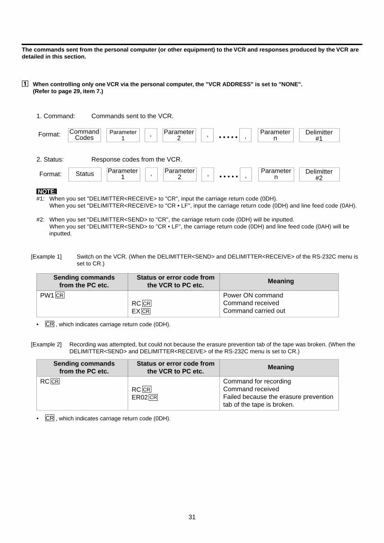
31
The commands sent from the personal computer (or other equipment) to the VCR and responses produced by the VCR aredetailed in this section.
11111 When controlling only one VCR via the personal computer, the "VCR ADDRESS" is set to "NONE".(Refer to page 29, item 7.)
CommandCodes , , • • • • • ,Format: Parameter
nParameter
2Parameter
1
1. Command: Commands sent to the VCR.
2. Status: Response codes from the VCR.
, , • • • • • ,StatusFormat: Parametern
Parameter2
Parameter1
Delimitter#1
Delimitter#2
[Example 1] Switch on the VCR. (When the DELIMITTER<SEND> and DELIMITTER<RECEIVE> of the RS-232C menu isset to CR.)
Sending commandsfrom the PC etc.
Meaning
PW1 CR
RC CR
EX CR
Status or error code fromthe VCR to PC etc.
Power ON commandCommand receivedCommand carried out
Sending commandsfrom the PC etc.
Meaning
RC CR
RC CR
ER02 CR
Status or error code fromthe VCR to PC etc.
Command for recordingCommand receivedFailed because the erasure preventiontab of the tape is broken.
[Example 2] Recording was attempted, but could not because the erasure prevention tab of the tape was broken. (When theDELIMITTER<SEND> and DELIMITTER<RECEIVE> of the RS-232C menu is set to CR.)
N#1: When you set "DELIMITTER<RECEIVE> to "CR", input the carriage return code (0DH).
When you set "DELIMITTER<RECEIVE> to "CR • LF", input the carriage return code (0DH) and line feed code (0AH).
#2: When you set "DELIMITTER<SEND> to "CR", the carriage return code (0DH) will be inputted.When you set "DELIMITTER<SEND> to "CR • LF", the carriage return code (0DH) and line feed code (0AH) will beinputted.
• CR , which indicates carriage return code (0DH).
• CR , which indicates carriage return code (0DH).

32
22222 When controlling two or more VCRs from a personal computer, the "VCR ADDRESS" of each VCR is set to the differentaddress (from VCR01 to VCR16, except NONE). ( Refer to page 29, item 7.)
• Input the "VCR ADDRESS (eg.VCR01)" that you want to control and the ", (comma)" before inputting the command code.• When you want to control all connected VCRs, inputs the "ALL" and ", (comma)" before inputting the command codes.
1. Command: Command codes from outside to the VCR.
2. Status: Response codes from the VCR to outside.
Format:
Format:
• • •,,,VCR ADDRESS Parameter2
Parameter1
Status
• • •,,CommandCodes
,VCR ADDRESSor ALL
Parameter1
Parameter2 ,
Parametern
Delimitter#1
,Parameter
nDelimitter
#2
N#1: When you set "DELIMITTER<RECEIVE> to "CR", input the carriage return code (0DH).
When you set "DELIMITTER<RECEIVE> to "CR • LF", input the carriage return code (0DH) and line feed code (0AH).
#2: When you set "DELIMITTER<SEND> to "CR", the carriage return code (0DH) will be inputted.When you set "DELIMITTER<SEND> to "CR • LF", the carriage return code (0DH) and line feed code (0AH) will beinputted.
[Example 1] Fast forward the tape in the VCR of the ID number VCR02. (When the DELIMITTER<SEND> andDELIMITTER<RECEIVE> of the RS-232C menu is set to CR.)
[Example 2] Set the clock of the all VCR connected to 12:27. (When the DELIMITTER<SEND> and DELIMITTER<RECEIVE>of the RS-232C menu is set to CR.)
USING WITH THE PERSONAL COMPUTER
Sending commandsfrom the PC etc.
Meaning
ALL,SC12,27 CR
VCR01, RC CR
VCR01, EX CR
VCR02, RC CR
VCR02, EX CR•••
VCR16, RC CR
VCR16, EX CR
Status or error code from theVCR to PC etc.
Command for recordingCommand received (VCR01)Command carried out (VCR01)Command received (VCR02)Command carried out (VCR02)
•••Command received (VCR16)Command carried out (VCR16)
• CR , which indicates carriage return code (0DH).• The order and number of the status responses from the VCRs to the PC or other controller may vary dependent upon the
number of VCRs and the ID number settings.
Sending commandsfrom the PC etc.
Meaning
VCR02,FF CR
VCR02, RC CR
VCR02, EX CR
Status or error code fromthe VCR to PC etc.
Command for fast forwarding (VCR02)Command received (VCR02)Command carried out (VCR02)
• CR , which indicates carriage return code (0DH).
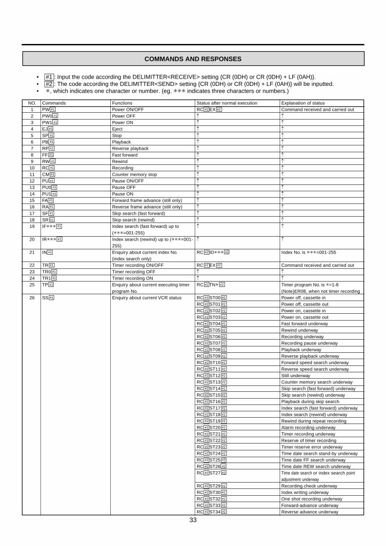
33
COMMANDS AND RESPONSES
• #1 : Input the code according the DELIMITTER<RECEIVE> setting CR (0DH) or CR (0DH) + LF (0AH).• #2 : The code according the DELIMITTER<SEND> setting CR (0DH) or CR (0DH) + LF (0AH) will be inputted.• +, which indicates one character or number. (eg. +++ indicates three characters or numbers.)
NO.123456789
10111213141516171819
20
21
22232425
26
CommandsPW #1
PW0 #1
PW1 #1
EJ #1
SP #1
PB #1
RP #1
FF #1
RW #1
RC #1
CM #1
PU #1
PU0 #1
PU1 #1
FA #1
RA #1
SF #1
SR #1
IF+++ #1
IR+++ #1
IN #1
TR #1
TR0 #1
TR1 #1
TP #1
SS #1
FunctionsPower ON/OFFPower OFFPower ONEjectStopPlaybackReverse playbackFast forwardRewindRecordingCounter memory stopPause ON/OFFPause OFFPause ONForward frame advance (still only)Reverse frame advance (still only)Skip search (fast forward)Skip search (rewind)Index search (fast forward) up to(+++=001-255)Index search (rewind) up to (+++=001-255)Enquiry about current index No.(index search only)Timer recording ON/OFFTimer recording OFFTimer recording ONEnquiry about current executing timerprogram No.Enquiry about current VCR status
Status after normal executionRC #2 EX #2
↑↑↑↑↑↑↑↑↑↑↑↑↑↑↑↑↑↑
↑
RC #2 ID+++ #2
RC #2 EX #2
↑↑RC #2 TN+ #2
RC #2 ST00 #2
RC #2 ST01 #2
RC #2 ST02 #2
RC #2 ST03 #2
RC #2 ST04 #2
RC #2 ST05 #2
RC #2 ST06 #2
RC #2 ST07 #2
RC #2 ST08 #2
RC #2 ST09 #2
RC #2 ST10 #2
RC #2 ST11 #2
RC #2 ST12 #2
RC #2 ST13 #2
RC #2 ST14 #2
RC #2 ST15 #2
RC #2 ST16 #2
RC #2 ST17 #2
RC #2 ST18 #2
RC #2 ST19 #2
RC #2 ST20 #2
RC #2 ST21 #2
RC #2 ST22 #2
RC #2 ST23 #2
RC #2 ST24 #2
RC #2 ST25 #2
RC #2 ST26 #2
RC #2 ST27 #2
RC #2 ST29 #2
RC #2 ST30 #2
RC #2 ST32 #2
RC #2 ST33 #2
RC #2 ST34 #2
Explanation of statusCommand received and carried out↑↑↑↑↑↑↑↑↑↑↑↑↑↑↑↑↑↑
↑
Index No. is +++=001-255
Command received and carried out↑↑Timer program No. is +=1-8(Note)ER08, when not timer recordingPower off, cassette inPower off, cassette outPower on, cassette inPower on, cassette outFast forward underwayRewind underwayRecording underwayRecording pause underwayPlayback underwayReverse playback underwayForward speed search underwayReverse speed search underwayStill underwayCounter memory search underwaySkip search (fast forward) underwaySkip search (rewind) underwayPlayback during skip searchIndex search (fast forward) underwayIndex search (rewind) underwayRewind during repeat recordingAlarm recording underwayTimer recording underwayReserve of timer recordingTimer reserve error underwayTime date search stand-by underwayTime date FF search underwayTime date REW search underwayTime date search or index search pointadjustment underwayRecording check underwayIndex writing underwayOne shot recording underwayForward-advance underwayReverse advance underway

34
Status after normal executionRC #2 EX #2
RC #2 LM+ #2
RC #2 EX #2
RC #2 CT+++++ #2
RC #2 EX #2
RC #2 MD+++(1),+(2) #2
RC #2 EX #2
↑
RC #2 ON+++(1)+(2) #2
RC #2 EX #2
RC #2 TD++(1),++(2),++(3),+(4) #2
RC #2 EX #2
RC #2 TI++(1),++(2),.++(3) #2
RC #2 MK+ #2
RC #2 EX #2
RC #2 LT++(1),++(2) #2
RC #2 EX #2
NO.27
28
293031
32
3334
35
36
37
38
394041
4243
CommandsLO+ #1
LM #1
CR #1
CT #1
MC+++ #1
MD #1
DP #1
DP+++ #1
PI #1
SD++(1),++(2),++(3) #1
DT #1
SC++(1),++(2) #1
TM #1
TD #1
PS++(1),++(2) #1
LC #1
PG+(1),+(2),++(3),++(4),++(5),++(6),+++(7),+(8) #1
FunctionsLock ON/OFF+:0=OFF, 1=ONEnquiry about current lock status & lockmodeCounter resetEnquiry about current count display valueSwitch over time mode to+++ = 003, L12, L24, 048, 072, 096, 120,168, 240, 360, 480, 720, 960, 000Enquiry about current time mode
Main menu ON/OFFSwitch screen page to(+++ :000=present time display100=MAIN MENU display110=Display menu120=TIME DATE SEARCH display130=PROGRAM menu140=RECORDING SET UP menu150=REAR TERMINAL menu160=MAINTENANCE menu161=POWER LOSS LIST162=ALARM LIST163=ALL MENU INITIALIZE164=POWER LOSS LIST CLEAR165=ALARM LIST CLEAR170=FIRST TIME SET UP menu171=TIME DATE ADJUST172=RS-232C setting menu)Enquiry about current screen page
Current date setting++(1) : Day, ++(2) : Month, ++(3) : YearEnquiry about current date
Current time setting++(1):Hour, ++(2):MinuteEnquiry about current timeEnquiry about power loss markMove date display position++(1) : Horizontal= 03-16 (mode 1, size large)= 05-28 (mode 1, size small)= 03-21 (mode 2,3, size large)= 00-28 ( mode 2,3, size small)++(2) Vertical= 02-30 (mode 1, size large or small)= 02-30 (mode 2,3, size large or small)Enquiry about date display positionTimer program setting+(1)Program No.=1-8+(2):Day of the week(0=SUN,1=MON,2=TUE,3=WED,4=THU,5=FRI,6=SAT,7=DAY,8=SPL)++(3):Rec starting hour=00-23++(4):Rec starting minute=00-59++(5):REC ending hour=00-23++(6):REC ending minute=00-59+++(7):REC time mode=003, L12, L24,048, 072, 096, 120, 168, 240, 360, 480,720, 960, 000, SKP+(8):REC mode 0=SP
Explanation of statusCommand received and carried out
+: 0=Lock off2=Lock on
Command received and carried out+++++=00000-99999Command received and carried out
+++(1)= 003, L12, L24, 048, 072, 096, 120,168, 240, 360, 480, 720, 960, 000+(2)= SPCommand received and carried out↑
+++(1) : same as item 34+(2) : Setting completed=0,
During setting=1Command received and carried out
++(1)-++(3) (same as item 36)+(4) :Day of the week 0=SUN, 1=MON, 2=TUE, 3=WED, 4=THU, 5=FRI, 6=SATCommand received and carried out
++(1) :Hour, ++(2) :Minute, ++(3):Second+: 0=Not displayed, 1=On displayCommand received and carried out
++(1),++(2) (=same as item 41)Command received and carried out(Note) An error (ER08) will occur if anattempt is made to program a timerprogram number that has already beenset. Clear the timer program contentswith the “CA+” command and then retry.
USING WITH THE PERSONAL COMPUTER
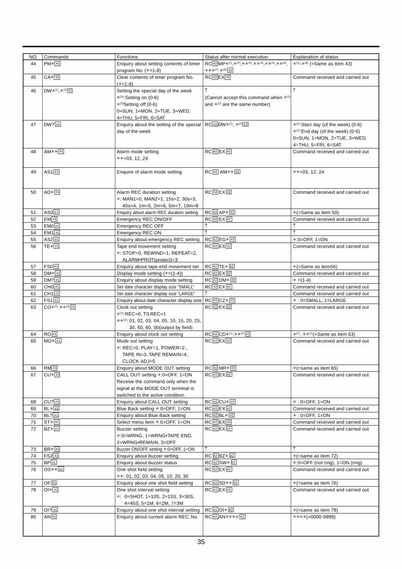
35
NO.44
45
46
47
48
49
50
515253545556
57585960616263
6465
6667
6869707172
73747576
7778
7980
Status after normal executionRC #2 MP+(1),+(2),++(3),++(4),++(5),++(6),+++(7) +(8) #2
RC #2 EX #2
↑(Cannot accept this command when +(1)
and +(2) are the same number)
RC #2 DW+(1), +(2) #2
RC #2 EX #2
RC #2 AM++ #2
RC #2 EX #2
RC #2 AP+ #2
RC #2 EX #2
↑↑RC #2 EG+ #2
RC #2 EX #2
RC #2 TE+ #2
RC #2 EX #2
RC #2 DM+ #2
RC #2 EX #2
↑RC #2 CZ+ #2
RC #2 EX #2
RC #2 CD+(1),++(2) #2
RC #2 EX #2
RC #2 MR+ #2
RC #2 EX #2
RC #2 CU+ #2
RC #2 EX #2
RC #2 BL+ #2
RC #2 EX #2
RC #2 EX #2
↑RC #2 BZ+ #2
RC #2 SW+ #2
RC #2 EX #2
RC #2 SD++ #2
RC #2 EX #2
RC #2 OI+ #2
RC #2 AN++++ #2
FunctionsEnquiry about setting contents of timerprogram No. (+=1-8)Clear contents of timer program No.(+=1-8)Setting the special day of the week+(1):Setting on (0-6)+(2)Setting off (0-6)0=SUN, 1=MON, 2=TUE, 3=WED,4=THU, 5=FRI, 6=SATEnquiry about the setting of the specialday of the week
Alarm mode setting++=03, 12, 24
Enquire of alarm mode setting
Alarm REC duration setting+: MAN1=0, MAN2=1, 15s=2, 30s=3,
45s=4, 1m=5, 2m=6, 5m=7, 10m=8Enquiry about alarm REC duration settingEmergency REC ON/OFFEmergency REC OFFEmergency REC ONEnquiry about emergency REC settingTape end movement setting+: STOP=0, REWIND=1, REPEAT=2,
ALARM•PROT(protect)=3Enquiry about tape end movement setDisplay mode setting (+=(1-4))Enquiry about display mode settingSet date character display size “SMALL”Set date character display size “LARGE”Enquiry about date character display sizeClock out setting+(1):REC=0, T/LREC=1++(2): 01, 02, 03, 04, 05, 10, 15, 20, 25,
30, 50, 60, 00(output by field)Enquiry about clock out settingMode out setting+: REC=0, PLAY=1, POWER=2 ,
TAPE IN=3, TAPE REMAIN=4,CLOCK ADJ=5
Enquiry about MODE OUT settingCALL OUT setting +:0=OFF, 1=ONReceive the command only when thesignal at the MODE OUT terminal isswitched to the active condition.Enquiry about CALL OUT settingBlue Back setting +:0=OFF, 1=ONEnquiry about Blue Back settingSelect menu item +:0=OFF, 1=ONBuzzer setting+:0=WRNG, 1=WRNG•TAPE END,2=WRNG•REMAIN, 3=OFFBuzzer ON/OFF setting +:0=OFF, 1=ONEnquiry about buzzer settingEnquiry about buzzer statusOne shot field setting++: 01, 02, 03, 04, 05, 10, 20, 30Enquiry about one shot field settingOne shot interval setting+: 0=SHOT, 1=10S, 2=15S, 3=30S,
4=45S, 5=1M, 6=2M, 7=3MEnquiry about one shot interval settingEnquiry about current alarm REC. No.
CommandsPM+ #1
CA+ #1
DW+(1),+(2) #1
DW? #1
AM++ #1
AS1 #1
AD+ #1
AS0 #1
EM #1
EM0 #1
EM1 #1
AS2 #1
TE+ #1
FS0 #1
DM+ #1
DM? #1
CH0 #1
CH1 #1
FS1 #1
CO+(1),++(2) #1
RO #1
MO+ #1
RM #1
CU+ #1
CU? #1
BL+ #1
BL? #1
ST+ #1
BZ+ #1
BR+ #1
FS2 #1
BP #1
OS++ #1
OF #1
OI+ #1
OI? #1
AN #1
Explanation of status+(1)-+(8) (=Same as item 43)
Command received and carried out
↑
+(1):Start day (of the week) (0-6)+(2):End day (of the week) (0-6)0=SUN, 1=MON, 2=TUE, 3=WED,4=THU, 5=FRI, 6=SATCommand received and carried out
++=03, 12, 24
Command received and carried out
+(=Same as item 50)Command received and carried out↑↑+:0=OFF, 1=ONCommand received and carried out
+(=Same as item56)Command received and carried out+ =(1-4)Command received and carried outCommand received and carried out+ : 0=SMALL, 1=LARGECommand received and carried out
+(1), ++(2)(=Same as item 63)Command received and carried out
+(=same as item 65)Command received and carried out
+ : 0=OFF, 1=ONCommand received and carried out+ : 0=OFF, 1=ONCommand received and carried outCommand received and carried out
↑+(=same as item 72)+:0=OFF (not ring), 1=ON (ring)Command received and carried out
+(=same as item 76)Command received and carried out
+(=same as item 78)++++(=0000-9999)

36
Error codes
NO.81
828384
85868788
8990
91929394
9596
9798
99
100101102
103
104105
106107
108109
CommandsAT+ #1
CA #1
PN #1
PT+ #1
PC #1
MI #1
HM? #1
WN #1
CA0 #1
RI+ #1
RI? #1
QV+ #1
QM #1
CL+ #1
RL #1
SM+ #1
SM? #1
RS? #1
TL+ #1
TL? #1
LP? #1
TF++(1), ++(2), ++(3) #1
TB++(1), ++(2), ++(3) #1
TS? #1
HD+ #1
HD? #1
MQ+ #1
SB1 #1
SV? #1
FunctionsEnquiry about alarm REC list report+: 0=about the alarm REC No. 1
1=about the second alarm REC fromthe last one
2=about the last alarm RECClear all alarm REC list contentsEnquiry about current power loss list No.Enquiry about power loss list report+: 0=about the first power loss
1=about the second power loss fromthe last one
2=about the last power lossClear all power loss list contentsInitialization of the settingEnquiry about the elapsed timeEnquiry about Warning information
Clear ER05REC IN setting+:0=SERIES, 1=REC-START/STOP2=SYNC RECEnquiry about REC IN settingQUASI-VSYNC setting +:0=OFF, 1=ONEnquiry about QUASI-VSYNC settingCALL OUT setting+:0=WRNG, 1=WRNG •TAPE END2=WRNG •TAPE REMAINEnquiry about CALL OUT settingDAY LIGHT SAVINGS setting+:0=OFF, 1=ONEnquiry about DAY LIGHT SAVINGS settingEnquiry about REPEAT REC TIMES
Tape length setting+:0=E-180, 1=E-240Enquiry about tape length settingEnquiry about tape remaining timeTime date FF search setting++(1) : Day , ++(2) : Hour , ++(3) : MinuteTime date REW search setting++(1) : Day , ++(2) : Hour , ++(3) : MinuteEnquiry about time date search settingPB head switch-over+:0=NORMAL,1=L/L, 2=R/R, 3=AUTOEnquiry about PB head switch-overVIDEO MODE setting+:0=COLOUR,1=B/WEnquiry about VIDEO MODEEnquiry about S-VHS information
Status after normal executionRC #2 AT++(1), ++(2), ++(3), ++(4), ++(5) #2
RC #2 EX #2
RC #2 PN++ #2
RC #2 PT++(1), ++(2), ++(3), ++(4), ++(5) #2
RC #2 EX #2
↑RC #2 HM+++++ #2
RC #2 WN++ #2
RC #2 EX #2
↑
RC #2 RI+ #2
RC #2 EX #2
RC #2 QV+ #2
RC #2 EX #2
RC #2 CL+ #2
RC #2 EX #2
RC #2 SM+ #2
RC #2 RS+++ #2
RC #2 EX #2
RC #2 TL+ #2
RC #2 LP+(1), ++(2) #2
RC #2 EX #2
↑
RC #2 TS++(1), ++(2), ++(3) #2
RC #2 EX #2
RC #2 HD+ #2
RC #2 EX #2
RC #2 SQ+ #2
RC #2 SV+ #2
Explanation of status++(1) : Day, ++(2) : Month, ++(3) :Year,++(4) : Hour, ++(5) : Minute
Command received and carried out++(=00-99)++(1) : Day, ++(2) : Month, ++(3) :Year,++(4) : Hour, ++(5) : Minute
Command received and carried out↑+++++(=Hour)++: Warning No. 0=not abnormal01=tape end03=video input missing04=clogged head05=reel rotation trouble06=loading motor trouble07=capstan motor trouble08=drum motor trouble09=tape loose, 10=switching power shortCommand received and carried out↑
+ : (=Same as item 90)Command received and carried out+:0=OFF, 1=ONCommand received and carried out
+ : (=Same as item 94)Command received and carried out
+:0=OFF, 1=ON+++:000-200,OVER ( more than 201 times )Command received and carried out
+ : (=Same as item 99)+(1) : Hour , ++(2) : MinuteCommand received and carried out
↑
++(1) : Day , ++(2) : Hour , ++(3) : MinuteCommand received and carried out
+ : (=Same as item 105)
+:0=COLOUR,1=B/W+:0=NORMAL,1=S-VHS
Meaning of errorNo power supplyNo cassette loadedBroken tape tab (Cannot REC)Beginning of the tapeTape endProblem with the tape, video input or VCR mechanismPresent time or timer program not yet set
No.1234567
ErrorsER00ER01ER02ER03ER04ER05ER06
USING WITH THE PERSONAL COMPUTER
Meaning of errorAlarm REC underway (Unable to change setting)UnfeasibleIncorrect commandIncorrect parameterOverflow of the VCR’s command receive bufferData not received correctly
No.89
10111213
ErrorsER07ER08ER10ER11ER12ER13

37
SELF DIAGNOSTIC FUNCTION
MonitorFluorescentdisplay REMEDYCAUSE TO TURN OFF THE INDICATION
The VCR uses a self diagnostic function to detect internal malfunctions during recording. Should a malfunction occur during record-ing, a corresponding indication appears on the monitor screen and the fluorescent display.The type of malfunction corresponding to the indication, and countermeasures, are given below.
WARNING DISPLAY
End
—
—
TAPE END
NO SIGNAL
CHECK
THE TAPE ENDS DUR-ING RECORDING
Rewind the tape andpress the EJECT button.
Check for loose connec-tions.
First, check the cassette. If there seems to be nothing wrong withthe cassette, try the recording operation again. If the indication“CHECK” is still displayed, change the cassette with a new oneand try the operation again. Otherwise, unplug the power cord andcontact your dealer.
LACK OF VIDEO SIG-NAL INPUT (NOTE 1)
CLOGGED HEAD(NOTE 2)
TAPE/ DECK TROUBLE
Turn off the indication on the fluorescentdisplay and on the screen by pressing theEJECT button or rewinding the tape.
N1. Lack of video input signal.
If the VCR is set to record and an input signal is not detected, the indication NO SIGNAL appears on the monitor screen and theCALL signal is output from the rear terminal.Check that the cable from the camera is not broken and the camera's power has not been lost.
2. About fouling of the head (CLOGGED HEAD).This VCR’s head cleaning function automatically removes any particles that may accumulate on the heads during 48H - 960H(SP) or 0H recording mode. If it cannot be entirely removed, a CLog indicator illuminates.
When a video signal is restored or therecord mode is cleared, the indication onthe screen turns off.
Eject the cassette andinsert it again. If theindication “CLog” is stilldisplayed, clean thevideo cassette tape. Ifthe VCR still shows theindication after clean-ing, contact your dealer.
When the recording mode is cleared, theindication on the fluorescent display turnsoff.
CLog —
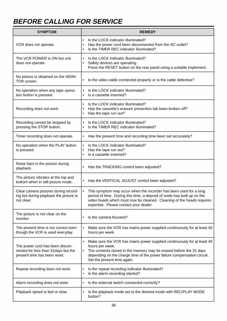
38
REMEDY
BEFORE CALLING FOR SERVICESYMPTOM
VCR does not operate.
The VCR POWER is ON but unitdoes not operate.
No picture is obtained on the MONI-TOR screen.
No operation when any tape opera-tion button is pressed.
Recording does not work.
Recording cannot be stopped bypressing the STOP button.
Timer recording does not operate.
No operation when the PLAY buttonis pressed.
Noise bars in the picture duringplayback.
The picture vibrates at the top andbottom when in still picture mode.
Clear camera pictures during record-ing but during playback the picture isnot clear.
The picture is not clear on themonitor.
The present time is not correct eventhough the VCR is used everyday.
The power cord has been discon-nected for less than 31days but thepresent time has been reset.
Repeat recording does not work.
Alarm recording does not work.
Playback speed is fast or slow.
• Is the LOCK indicator illuminated?• Has the power cord been disconnected from the AC outlet?• Is the TIMER REC indicator illuminated?
• Is the LOCK indicator illuminated?• Safety devices are operating.
Press the RESET button on the rear panel using a suitable implement.
• Is the video cable connected properly or is the cable defective?
• Is the LOCK indicator illuminated?• Is a cassette inserted?
• Is the LOCK indicator illuminated?• Has the cassette’s erasure prevention tab been broken off?• Has the tape run out?
• Is the LOCK indicator illuminated?• Is the TIMER REC indicator illuminated?
• Has the present time and recording time been set accurately?
• Is the LOCK indicator illuminated?• Has the tape run out?• Is a cassette inserted?
• Has the TRACKING control been adjusted?
• Has the VERTICAL ADJUST control been adjusted?
• This symptom may occur when the recorder has been used for a longperiod of time. During this time, a deposit of oxide has built up on thevideo heads which must now be cleaned. Cleaning of the heads requiresexpertise. Please contact your dealer.
• Is the camera focused?
• Make sure the VCR has mains power supplied continuously for at least 40hours per week.
• Make sure the VCR has mains power supplied continuously for at least 40hours per week.
• The contents stored in the memory may be erased before the 31 daysdepending on the charge time of the power failure compensation circuit.Set the present time again.
• Is the repeat recording indicator illuminated?• Is the alarm recording started?
• Is the external switch connected correctly?
• Is the playback mode set to the desired mode with REC/PLAY MODEbutton?
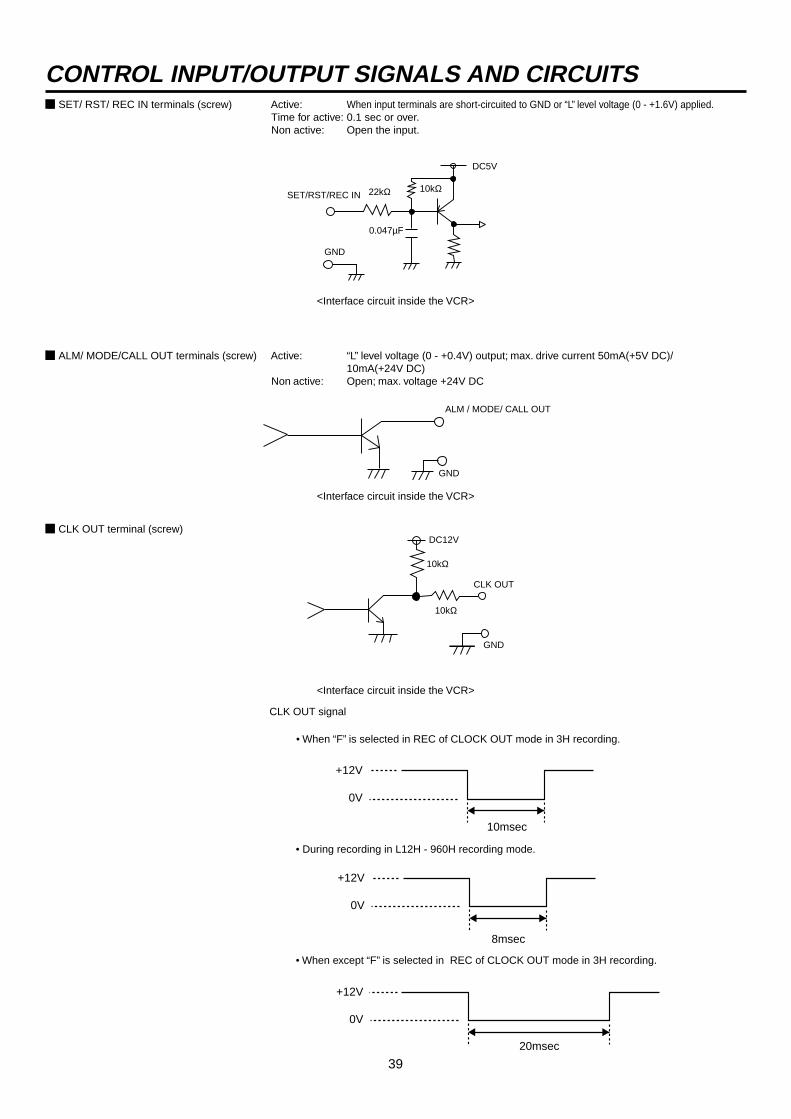
39
CONTROL INPUT/OUTPUT SIGNALS AND CIRCUITS2 SET/ RST/ REC IN terminals (screw) Active: When input terminals are short-circuited to GND or “L” level voltage (0 - +1.6V) applied.
Time for active: 0.1 sec or over.Non active: Open the input.
DC5V
GND
SET/RST/REC IN
0.047µF
22kΩ 10kΩ
<Interface circuit inside the VCR>
2 ALM/ MODE/CALL OUT terminals (screw) Active: “L” level voltage (0 - +0.4V) output; max. drive current 50mA(+5V DC)/10mA(+24V DC)
Non active: Open; max. voltage +24V DC
GND
ALM / MODE/ CALL OUT
<Interface circuit inside the VCR>
2 CLK OUT terminal (screw)
<Interface circuit inside the VCR>
10kΩ
DC12V
CLK OUT
10kΩ
GND
CLK OUT signal
• When “F” is selected in REC of CLOCK OUT mode in 3H recording.
+12V
0V
20msec
• When except “F” is selected in REC of CLOCK OUT mode in 3H recording.
+12V
0V
8msec
• During recording in L12H - 960H recording mode.
+12V
0V
10msec
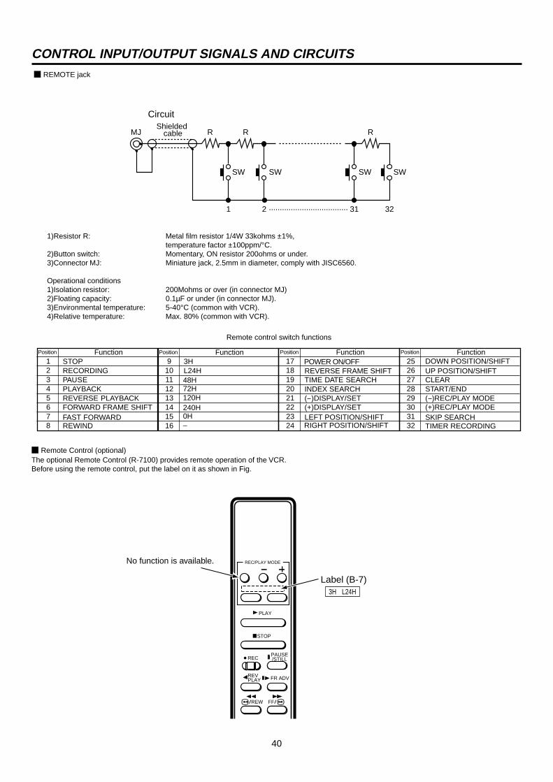
40
72H120H
Function
R
1 2 ···································· 31 32
SW
MJ R R
SW SW SW
Shielded cable
2 REMOTE jack
1)Resistor R: Metal film resistor 1/4W 33kohms ±1%,temperature factor ±100ppm/°C.
2)Button switch: Momentary, ON resistor 200ohms or under.3)Connector MJ: Miniature jack, 2.5mm in diameter, comply with JISC6560.
Operational conditions1)Isolation resistor: 200Mohms or over (in connector MJ)2)Floating capacity: 0.1µF or under (in connector MJ).3)Environmental temperature: 5-40°C (common with VCR).4)Relative temperature: Max. 80% (common with VCR).
Remote control switch functions
Position
12345678
STOPRECORDINGPAUSEPLAYBACKREVERSE PLAYBACKFORWARD FRAME SHIFTFAST FORWARDREWIND
FunctionPosition
910111213141516
3HL24H
FunctionPosition
1718192021222324
POWER ON/OFFREVERSE FRAME SHIFTTIME DATE SEARCHINDEX SEARCH( )DISPLAY/SET(+)DISPLAY/SETLEFT POSITION/SHIFTRIGHT POSITION/SHIFT
FunctionPosition
2526272829303132
DOWN POSITION/SHIFTUP POSITION/SHIFTCLEARSTART/END( )REC/PLAY MODE
SKIP SEARCHTIMER RECORDING
Circuit
2 Remote Control (optional)The optional Remote Control (R-7100) provides remote operation of the VCR.Before using the remote control, put the label on it as shown in Fig.
Label (B-7)3H L24H
(+)REC/PLAY MODE
PLAY
STOP
REC PAUSE/STILL
REVPLAY FR ADV
FF//REW
REC/PLAY MODE
CONTROL INPUT/OUTPUT SIGNALS AND CIRCUITS
48H
0H–
240H
No function is available.

41
Tape Format: VHS 1/2" width high-density video cassette tape.Power Source: AC100-230V, 50/60Hz.Power Consumption: Approx.20watts.Television System: 625 lines, 50 field PAL-type colour system.Heads-Video: 4 rotary single crystal heads.Luminance Signal: Frequency modulation recording.Colour Signal: Low frequency conversion, sub-carrier phase shift recording.Audio Track: 1 track.Tape Speed and RecordingTime (with E-180 cassette): Mode Time Speed Recording interval Video signal Audio signal Tape drive
3H 3hrs 23.39mm/sec 20msec./Field Continuous Recordable ContinuousL12H 15hrs 4.68mm/sec 100msec./Field Time lapse Recordable Continuous (Slow)L24H 27hrs 2.60mm/sec 180msec./Field Time lapse Recordable Continuous (Slow)48H 51hrs – 340msec./Field Time lapse Not recorded Time lapse72H 75hrs – 500msec./Field Time lapse Not recorded Time lapse96H 99hrs – 660msec./Field Time lapse Not recorded Time lapse
120H 123hrs – 820msec./Field Time lapse Not recorded Time lapse168H 171hrs – 1140msec./Field Time lapse Not recorded Time lapse240H 243hrs – 1620msec./Field Time lapse Not recorded Time lapse360H 363hrs – 2420msec./Field Time lapse Not recorded Time lapse480H 483hrs – 3220msec./Field Time lapse Not recorded Time lapse720H 723hrs – 4820msec./Field Time lapse Not recorded Time lapse960H 963hrs – 6420msec./Field Time lapse Not recorded Time lapse
0H – – – Time lapse Not recorded Time lapse
Fast Forward/Rewind Time: Approx. 140sec. with E-180 cassette.Audio/Control: 1 stationary head.Erase: 1 full-track head.Motors: 3 motors-drum/capstan direct drive system.Video Input: 1.0Vp-p, 75ohms BNC plug. Y: 1.0 Vp-p, 75 ohms, C: 0.286 Vp-p, 75 ohms, S-connector.Audio Input: -8dBs, 50kohms, RCA plug.Microphone Input: -67dBs, 600ohms, mini mic jack.Video Output: 1.0Vp-p, 75ohms BNC plug. Y: 1.0 Vp-p, 75 ohms, C: 0.286 Vp-p, 75 ohms, S-connector.Audio Output: -6dBs, 1kohms, RCA plug.Horizontal Resolution: More than 400 lines (S-VHS mode).
More than 240 lines (VHS mode).Audio Frequency Response: 70Hz- 7kHz (3H mode).Signal-to-Noise Ratio: Video: better than 42dB.
Audio: better than 43dB.Operating Temperature: 41°F-104°F (5°C to 40°C).Relative Humidity: Max.80(%)Dimensions: 16.7(W)x12.4(D)x3.7(H)(in.).(Jog dial included) 425(W)x315(D)x93(H)(mm).Weight: 10 lbs (4.5kg.)Alarm Recording Time: Timed: 15 sec/30 sec/45 sec/1 min./2 min./5 min./10 min.
Manual 1: Until the alarm reset switch is switched on. Manual 2: Until the alarm set switch is switched off.Display Format: DISPLAY MODE 1: (Day)-(Month)-(Year) (Hour) : (Minute) : (Second) (Daylight saving time symbol or power failure symbol) (Alarm recording no.)
DISPLAY MODE 2: (Month)-(Day)-(Year) (Day of week) (Alarm recording no.),(Hour) : (Minute) : (Second) (Daylight saving time symbol or power failure symbol) (Recording mode)
Display Position: In any position.Memory Program: 8 programs- daily start and stop time for one week.Memory Backup: Lasts 31days.Elapsed Time Indicator: The maximum of 89,999 hours.CONNECTORSSET Input: Screw terminal for starting alarm recording.RST Input: Screw terminal for finishing alarm recording or for adjusting on-screen clock.REC Input: Screw terminal for starting/finishing recording, for series recording or for synchronous recording.GND: Screw terminal for ground.ALM Output: Screw terminal for output while alarm recording is under way.CLK Output: Screw terminal to command camera switching.MODE Output: Screw terminal for indication of VCR selected mode.CALL Output: Screw terminal for external warning device or for series recording.REMOTE Jack: Jack for connecting the remote control unit.RS-232C interface: D-SUB 9 pin connector.Rating:ALM/CALL/MODE Active: “Low” level, max. Current 50mA (+5VDC)/10mA (+24VDC).
Non active: Open, max. Voltage +24V DC.SET/RST/REC Active: When terminals are short-circuited or “Low” level voltage applied.
Non active: Open, max. Voltage +17V DC.CLK Recording: A pulse of the frequency division ratio selected by REAR TERMINAL menu.
Weight and dimensions shown are approximate.Design and specifications are subject to change without notice.
SPECIFICATIONS

872C193C3 PRINTED IN JAPAN