Embed Size (px)
Citation preview

Version: PEIKKO GROUP 01/2015
TECHNICALMANUAL
HPM® Rebar Anchor Bolt Easy and Fast Bolted Connections

www.peikko.com
HPM Anchor BoltFor bolted connections
System benefi ts• Standardized and approved rebar anchor
bolt system
• Approved design parameters
• Quick deliveries directly from stock
• Certifi ed production
• Wide range of products for all anchoring pur-
poses
• Accessories for quick and easy installation
• Easy to design with free Peikko Designer®
software
HPM Rebar Anchor Bolts are used to anchor concrete or steel
structures and machinery into concrete base structures. The
anchors are embedded into concrete and the structures are fas-
tened to bolts by nuts and washers. The joint between two struc-
tures is then grouted.
The system consists of a wide range of headed and straight an-
chor bolts, installation accessories, and tools for designers.
Headed bolts are used typically in shallow structures for end an-
choring, whereas straight bolts are used for lap splices. In addi-
tion to plain fi nish bolts, the products are also available as ECO
or Hot-Dip galvanized. Installation templates are provided to
ensure easy and correct installation of the anchor bolts.

Revision: 001*
Contents
4
1. Product Properties ...................................... 4
1.1 Structural behavior . . . . . . . . . . . . . . . . . . . . . . . . . . . . . 6
1.1.1 Temporary conditions ....................................................................6
1.1.2 Final conditions .............................................................................6
1.2 Application conditions . . . . . . . . . . . . . . . . . . . . . . . . . . 7
1.2.1 Loading and environmental conditions ............................................7
1.2.2 Interaction with the base structure ..................................................8
1.2.3 Positioning of the anchor bolts .......................................................8
1.3 Other properties . . . . . . . . . . . . . . . . . . . . . . . . . . . . . . . 9
2. Resistances .............................................. 11
2.1 Tensile, compressive, and shear resistances . . . . . . . 11
2.2 Combined axial and shear load . . . . . . . . . . . . . . . . . . 15
2.3 Fire resistance . . . . . . . . . . . . . . . . . . . . . . . . . . . . . . . . 15
About HPM Rebar Anchor Bolt
16
18
20
21
24
25
26
27
A1: Concrete cone reinforcement ..........................................................18
A2: Splitting reinforcement ...................................................................19
B1: Edge reinforcement ........................................................................20
C1: Concrete cone reinforcement for punching ......................................21
C2: Partially loaded areas, Splitting reinforcement ..................................22
Selecting HPM Rebar Anchor Bolt
Annex A - Supplementary reinforcement to resist tension load
Annex B - Supplementary reinforcement to resist shear load
Annex C - Supplementary reinforcement to resist compression load
Annex D - Transverse reinforcement in the lap zone
Annex E - Alternative use of HPM P Anchor Bolts
Annex F - Alternative means to transfer shear load
Installation of HPM Rebar Anchor Bolts

HPM Rebar Anchor Bolt4
About HPM Rebar Anchor Bolt
1. Product Properties
HPM Anchor Bolts are cast-in-place anchors used to connect structural and non-structural elements to concrete in
all types of buildings, warehouses, halls, bridges, dams, and power plants.
HPM Anchor Bolts are available in several standard models that are suitable for diff erent application solutions,
loading conditions, and cross-sections. Anchor bolts are cast into concrete and transfer loads from the attachment
to the base structure.
The product range consists of
• Headed anchor bolts, type HPM L
• Straight anchor bolts, type HPM P
• Installation templates
HPM L Anchor Bolt HPM P Anchor Bolt
Type L bolt anchorage is achieved with a headed stud. Loads are transferred through the bearing of the head against
hardened concrete. Due to their relatively short anchorage length, HPM L Anchor bolts are particularly suitable for
use in shallow structures (e.g. foundations, slabs, beams).
Type P bolt anchorage is achieved by splicing, whereby the bolt overlaps the main reinforcement. Loads are trans-
ferred through the bond of the ribbed bars. The primary use of HPM P Anchor Bolts is in structures with suffi cient
depth (e.g. base columns, columns). Alternative usages are shown in Annex E.
HPM Anchor Bolts are pre-designed to be compatible with HPKM Column Shoes, SUMO Wall Shoes, and Beam Shoes,
providing a solution for most precast connections (e.g. column to foundation, column to base column, column to
column, wall to foundation, wall to wall, beam to column, beam to wall), as well as to secure steel columns or even
machine fi xings.
Anchor bolts are cast into the base structure together with the main and supplementary reinforcement, as detailed
in Annexes A, B, C, and D of this manual. The connection is achieved by fastening the anchor bolt to the base plate
using nuts and washers. To fi nalize the connection, the joint is grouted with non-shrinking grouting material.
Peikko Bolted Connections can be designed to resist axial forces, bending moments, shear forces, combinations of
the above, and fi re exposure. The appropriate type and quantity of HPM Anchor Bolts to be used in a connection may
be selected and the resistance of the connection verifi ed by using the Peikko Designer® software (download from
www.peikko.com).

5Version: Peikko Group 01/2015
About HPM Rebar Anchor Bolt
Figure 1. HPM L Anchor Bolts in a concrete column to footing
connection.
Figure 2. HPM P Anchor Bolts in a steel column to base
column connection.column connection.

HPM Rebar Anchor Bolt6
About HPM Rebar Anchor Bolt
1.1 Structural behavior
The loads on fi xtures are transmitted to the anchor bolts as statically equivalent, tension, compression, and shear
forces. Moment can be resisted by development of a force couple between tensile and compressive forces. The select-
ed size and number of anchor bolts should be suffi cient for the load.
1.1.1 Temporary conditions
In the erection stage, the forces acting on anchor bolts are caused principally by self-weight of the attachment as
well as by the bending moment and shear force due to wind load. Since the joint is not grouted, all of the forces are
carried solely by anchor bolts. In addition, bolts must be verifi ed for buckling and bending. The open joint between
the attachment and the base structure must be grouted with a non-shrink grouting material and the grout must
harden before loads from other structures can be applied.
1.1.2 Final conditions
In the fi nal stage, after the grout has reached the designed strength, the connection acts as a reinforced-concrete
structure. The grout serves as the connection between the attachment and the base structure, transferring com-
pression and shear loads. The grout must have a design compressive strength at least equal to the strength of the
highest grade of concrete used in the connected elements.
Figure 3. Structural behavior of the bolted connection under temporary and fi nal conditions.
Temporary Stage Final Stage
VEd,0
Compression in
concrete and grout
NEd,0
MEd,0
Fst,0
z Fsc,0
Fcc
VEd
NEd
MEd
Fst
z
z’
Fsc

7Version: Peikko Group 01/2015
About HPM Rebar Anchor Bolt
1.2 Application conditions
The standard models of HPM Anchor Bolts are pre-designed for use under the conditions mentioned in this section.
If these conditions are not met, please contact Peikko Technical Support for custom-designed HPM Anchor Bolts.
1.2.1 Loading and environmental conditions
HPM Anchor Bolts are designed to carry static loads. To ensure resistance to corrosion the concrete cover of HPM
Anchor Bolts including washers and nuts must observe the minimum values determined according to the environ-
mental exposure class and intended operating life. As an alternative to concrete cover, Peikko off ers two standard
surface coating options: ECO Galvanizing and Hot-Dip Galvanizing. Other anti-corrosion methods such as painting
on site can also be utilized. For further information please contact Peikko Technical Support.
ECO Galvanizing is an economical and ecological way to protect bolts against corrosion, which allows anchor bolts to
be galvanized partly or completely. The galvanizing method is a thermally sprayed zinc coating (according to EN ISO
2063). The minimum coating thickness is 100 μm, which fulfi lls environmental class C3 of standard EN 9223-1002.
Hot-Dip Galvanized bolts (according to EN ISO 1461) are dipped completely into galvanized material. The minimum
coating thickness is 55 μm, which fulfi lls environmental class C3 of standard EN 9223-1002.
Examples for ordering galvanized bolts:
• ECO Galvanized => Name: HPM24P-ECO
• Hot-Dip Galvanized => Name: HPM30L-HDG
Figure 4. ECO Galvanized Bolt.
Table 1. Protection of anchor bolts against corrosion in diff erent environmental conditions.
Structural Class: S4, Allowance for deviation: Δcdev=10 mm.
Exposure Class
Required nominal concrete cover of anchor bolts
according to EN 1992-1-1
cnom [mm]
X0 20
XC1 25
XC2 / XC3 35
XC4 40
XD1 / XS1 45
XD2 / XS2 50
XD3 / XS3 55
HPM Rebar Anchor Bolt8
About HPM Rebar Anchor Bolt
1.2.2 Interaction with base structure
HPM Anchor Bolts are pre-designed for use in reinforced base structures (e.g. foundations, slabs, base columns,
columns, walls). The standard properties of HPM Anchor Bolts are valid for reinforced normal weight concrete with
a strength class in the range C20/25 to C50/60. The anchor bolt may be anchored in cracked and non-cracked con-
crete. In general, it is conservative to assume that the concrete will be cracked over its service life.
1.2.3 Positioning of the anchor bolt
HPM Anchor Bolts are embedded in concrete up to the marking of the anchorage depth. Where possible, anchor bolts
should be arranged symmetrically. The layout must also be coordinated with existing reinforcement to ensure that
the bolts can be installed in the intended location.
Figure 5. Examples with layout patterns of HPM Anchor Bolts.
Figure 6. Installed HPM L Anchor Bolt.
When placing HPM L Anchor Bolts, the spacing (smin), edge distance (cmin), and base structure thickness (hmin) must
not fall below the minimum values shown in Table 2. It should be noted that the minimum thicknesses (hmin) in Table
2 are for base structures cast directly against soil, hmin = hef + k + cnom, hence cnom = 85 mm.
Table 2. Positioning of HPM L bolts in base structure.
Anchor Bolt cmin [mm] smin [mm] hmin [mm] hef [mm] k [mm]
HPM 16 L 50 80 260 165 10
HPM 20 L 70 100 320 223 12
HPM 24 L 70 100 385 287 13
HPM 30 L 100 130 435 335 15
HPM 39 L 130 150 605 502 18
When placing HPM P Anchor Bolts, the minimum edge distance should comply with the concrete cover thickness
according to EN 1992-1-1, section 4. The bolts must be spaced to prevent bundles from forming and should fulfi ll the
requirements for lapped bars, in EN 1992-1-1, sections 8.2 and 8.7.
≥h
min
hef
k
c no
m
≥cmin ≥smin ≥cmin

9Version: Peikko Group 01/2015
About HPM Rebar Anchor Bolt
Ribbed Bars B500B EN 10080
Washers S355J2 + N EN 10025-2
Nuts Property class 8 EN ISO 4032 / EN 24032
Manufacturing method
Ribbed Bars Mechanical cutting
Threads Rolling
Anchor head Forging
Manufacturing tolerances
Length ± 10 mm
Thread length + 5mm, - 0 mm
1.3 Other properties
HPM Anchor Bolts are fabricated of ribbed reinforcement steel bars with the following material properties:
Standard delivery for each anchor bolt includes two hexagonal nuts and two washers:
Peikko Group’s production units are externally controlled and periodically audited on the basis of production cer-
tifi cations and product approvals by various organizations, including Inspecta Certifi cation, VTT Expert Services,
Nordcert, SLV, TSUS, and SPSC, among others.

HPM Rebar Anchor Bolt10
About HPM Rebar Anchor Bolt
Table 3. Dimensions [mm], weight [kg], and color codes of HPM L Anchor Bolts.
HPM 16 L HPM 20 L HPM 24 L HPM 30 L HPM 39 L
M M16 M20 M24 M30 M39
A 140 140 170 190 200
Stress
area of the
thread
157 245 352 561 976
Ø 16 20 25 32 40
L 280 350 430 500 700
Washer Ø 40-6 Ø 44-6 Ø 56-6 Ø 65-8 Ø 90-10
hef 165 223 287 335 502
dh 38 46 55 70 90
k 10 12 13 15 18
Weight 0,7 1,2 2,2 4,1 9,2
Color code Yellow Blue Gray Green Orange
HPM 16 P HPM 20 P HPM 24 P HPM 30 P HPM 39 P
M M16 M20 M24 M30 M39
A 140 140 170 190 200
Stress
area of the
thread
157 245 352 561 976
Ø 16 20 25 32 40
L 810 1000 1160 1420 2000
Washer Ø 40-6 Ø 44-6 Ø 56-6 Ø 65-8 Ø 90-10
Weight 1,5 2,8 4,9 9,8 21,8
Color code Yellow Blue Gray Green Orange
Table 4. Dimensions [mm], weight [kg], and color codes of HPM P Anchor Bolts.
Ø
ML
hef
k
dh
A
Ø
M
L
A

11Version: Peikko Group 01/2015
About HPM Rebar Anchor Bolt
2. Resistances
2.1 Tensile, compressive, and shear resistances
The resistances of HPM Anchor Bolts are determined by a design concept that makes reference to the following
standards:
• Specifi cation CEN/TS 1992-4-1:2009
• Specifi cation CEN/TS 1992-4-2:2009
• EN 1992-1-1:2004/AC:2010
• EN 1993-1-1:2005/AC:2009
• EN 1993-1-8:2005/AC:2005
• ETA-02/0006: ETA-approval
• ETA-13/0603: ETA-approval
The resistance of HPM Anchor Bolt connections is defi ned by bolt steel or anchorage to concrete strength. The re-
quired verifi cations are summarized later in this section. If the anchor bolt’s tensile or shear steel resistance cannot
be fully developed due to concrete failure then the supplementary reinforcement may be used to carry the forces
from the anchor bolt. It is recommended that the resistance be calculated and the required reinforcement for the
bolted connections be assigned using the Peikko Designer® software.
Table 5. Design values for tensile or compressive resistance of individual HPM Anchor Bolt. (Steel strength).
Table 6. Design values for shear resistance of individual HPM Anchor Bolt. (Steel strength).
The resistances are determined in accordance with ETA-13/0603.
HPM 16 HPM 20 HPM 24 HPM 30 HPM 39
NRd
NRd.0
[kN] 62 96 139 220 383
Anchor BoltVRd [kN]
Final Stage
VRd.0 [kN]
Erection
Stage
tGrout
[mm]
HPM 16 20 5 50
HPM 20 31 10 50
HPM 24 45 18 50
HPM 30 72 37 50
HPM 39 125 72 60
NOTE 1: Resistances VRd and VRd,0 in Table 6 are valid for height of joint equal to tGrout.
NOTE 2: Resistances shown in Tables 5 and 6 are without simultaneous action of axial and shear load. For combined
resistance, see section 2.2 of this manual.
Figure 7. Loads and parameters characterizing the joint.
NEd
VEd
tR
hnut
db
db /
2t G
rou
tt Fi
x
Height of the joint
db = diameter of stress area in thread
hnut = thickness of nut
tR = equivilent span of anchor bolt
= tGrout - hnut + db / 2

HPM Rebar Anchor Bolt12
About HPM Rebar Anchor Bolt
Table 7. Required verifi cation for HPM Anchor Bolts loaded in tension.
The use of Peikko Designer® software is recommended to prove the resistance
of the following verifi cations
Failure Mode ExampleHPM L
Anchor Bolts
HPM P
Anchor Bolts
Steel strengthRequired
(for most loaded bolt)
Required
(for most loaded bolt)
Pull-out strengthRequired
(for most loaded bolt)Not applicable
Concrete cone strength 1)Required
(for anchor group)Not applicable
Splitting strength 2)Required
(for anchor group)Not applicable
Blow-out strength 3)Required
(for anchor group)Not applicable
Splicing length 4) Not applicableRequired
(for most loaded bolt)
1) Not required if supplementary reinforcement is provided according to Annex A1.
2) Not required if the edge distance in all directions c ≥ 1,5hef for one bolt and c ≥ 1,8hef for fastenings with
more than one anchor bolt or if supplementary reinforcement is provided according to Annex A2.
3) Not required if the edge distance in all directions c ≥ 0,5hef.
4) See Annex D for required transverse reinforcement in the lap zone.
l0

13Version: Peikko Group 01/2015
About HPM Rebar Anchor Bolt
Table 8. Required verifi cation for HPM Anchor Bolts loaded in compression.
The use of Peikko Designer® software is recommended to prove the resistance
of the following verifi cations
Failure Mode ExampleHPM L
Anchor Bolts
HPM P
Anchor Bolts
Steel strengthRequired
(for most loaded bolt)
Required
(for most loaded bolt)
Buckling strength 1)Required
(for most loaded bolt)
Required
(for most loaded bolt)
Punching strength under
the anchor head 2)
Required
(for anchor group)Not applicable
Splicing length 3) Not applicableRequired
(for most loaded bolt)
Partially loaded areas 4)
• Local crushing
• Transverse tension forces
Required only in the fi nal
stage
(for the base structure)
Required only in the fi nal
stage
(for the base structure)
1) Not required (according to ETA-13/0603) if the height of the joint does not exceed the grouting thicknesses
stated in the installation instructions of this manual. See Table 6 for tGrout.
2) Not required if the thickness of the base structure ensures a suffi cient concrete layer under the anchor head
or if supplementary reinforcement is provided. Details can be found from Annex C1.
3) See Annex D for the required transverse reinforcement in the lap zone.
4) See Annex C2 for design guidelines and the required splitting reinforcement.
l0
HPM Rebar Anchor Bolt14
About HPM Rebar Anchor Bolt
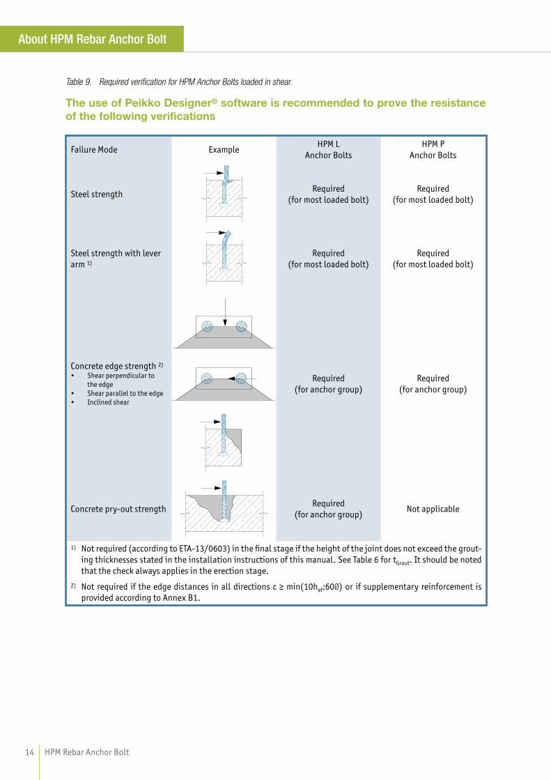
Table 9. Required verifi cation for HPM Anchor Bolts loaded in shear.
The use of Peikko Designer® software is recommended to prove the resistance
of the following verifi cations
Failure Mode ExampleHPM L
Anchor Bolts
HPM P
Anchor Bolts
Steel strengthRequired
(for most loaded bolt)
Required
(for most loaded bolt)
Steel strength with lever
arm 1)
Required
(for most loaded bolt)
Required
(for most loaded bolt)
Concrete edge strength 2)
• Shear perpendicular to
the edge
• Shear parallel to the edge
• Inclined shear
Required
(for anchor group)
Required
(for anchor group)
Concrete pry-out strengthRequired
(for anchor group)Not applicable
1) Not required (according to ETA-13/0603) in the fi nal stage if the height of the joint does not exceed the grout-
ing thicknesses stated in the installation instructions of this manual. See Table 6 for tGrout. It should be noted
that the check always applies in the erection stage.
2) Not required if the edge distances in all directions c ≥ min(10hef;60Ø) or if supplementary reinforcement is
provided according to Annex B1.

15Version: Peikko Group 01/2015
About HPM Rebar Anchor Bolt
2.2 Combined axial and shear load
When axial and shear forces strain the bolt simultaneously the interaction should be checked by satisfying the fol-
lowing equations for diff erent failure modes and design stages.
WITH RESPECT TO STEEL VERIFICATIONS
Bolts in Erection Stage
The simultaneous axial force and shear force in each bolt shall satisfy the condition:,, + ,, 1
Bolts in Final Stage
The simultaneous tensile force and shear force in each bolt shall satisfy the condition:
, + 1
1
where
VRd,0 = shear resistance of bolt, Erection Stage
VRd = shear resistance of bolt, Final Stage
NRd,0 = axial resistance of bolt, Erection Stage
NRd = axial resistance of bolt, Final Stage
VEd,0 = shear load on a single bolt, Erection Stage
VEd = shear load on a single bolt, Final Stage
NEd,0 = axial load on a single bolt, Erection Stage
NEd = axial load on a single bolt, Final Stage
WITH RESPECT TO CONCRETE VERIFICATIONS (applies only for HPM L Anchor Bolts)
Bolts without supplementary reinforcement
The simultaneous tensile force and shear force shall satisfy the condition:
|βN|1,5 + |βV|1,5 ≤ 1
Bolts with supplementary reinforcement
The simultaneous tensile force and shear force shall satisfy the condition:
|βN |2⁄3 + |βV |2⁄3 ≤ 1
If the supplementary reinforcement is designed to carry tension and shear forces, Eq. (48) applies.
where
βN = largest degree of utilization from concrete verifi cations under tensile force
βV = largest degree of utilization from concrete verifi cations under shear force
NOTE: Failure modes βN and βV are those not covered by supplementary reinforcement
2.3 Fire resistance
The fi re resistance of bolted connection should be verifi ed in accordance with EN 1992-1-2. The fi re design of col-
umn connections is implemented into Peikko Designer® to enable quick and easy proof of load-bearing function for
concrete column connections with HPM Anchor Bolts when exposed to fi re. If the fi re resistance of the connection
is insuffi cient, the concrete cover must be increased or alternative means used to reach the intended fi re resistance
class. Please contact Peikko Technical Support for custom designs.
1
1
1
1
ETA-13/0603, Eq. (1)
ETA-13/0603, Eq. (10)
ETA-13/0603, Eq. (11)
CEN/TS 1992-4-2, Eq. (48)
CEN/TS 1992-4-2, Eq. (49)

HPM Rebar Anchor Bolt16
Selecting HPM Rebar Anchor Bolt
The following aspects must be considered when selecting an appropriate type of HPM Anchor Bolt to be used in
bolted connections:
• Resistances
• Properties of the grouting
• Properties of the base structure
• Position and arrangement of the anchor bolts in the base structure
• Design value of actions
The resistance of Peikko Bolted Connections should be verifi ed for the following design situations:
• Erection stage
• Final stage
• Fire situation
• Environmental exposure conditions
Peikko Designer® Column Connection software
Peikko Designer® is software to be used for designing column connections with Peikko’s products. It can be down-
loaded free of charge from www.peikko.com. The Column Connection module enables the user to design connections
to resist actual loadings and optimize the connections to meet the requirements of the entire project. The software’s
output reports can also be used to verify the design and output drawings as details of the connection. The summary
of the products in the project helps to plan material fl ow during construction.
Figure 8. User interface of Peikko Designer® Column Connection.

17Version: Peikko Group 01/2015
Selecting HPM Rebar Anchor Bolt
Typically, the following steps are used for the selection procedure:
USER INPUT
• Materials for column, structure under column, and grouting
• Geometries of the column and structure under column
• Design values of the actions – erection, fi nal, and fi re stages
• NOTE: Second order eff ects should be included in the load case
• Type of column shoes and anchor bolts
• Column shoe arrangement
• Column reinforcement (optional)
PEIKKO DESIGNER OUTPUT
• N-M interaction diagram (axial force-bending moment diagram) of joint in fi nal and fi re stage
• N-M interaction diagram of reinforced column
• Calculation results for column connection in fi nal stage
• Calculation results for column connection in erection stage
• Supplementary reinforcement details
• Summary of products in the project

HPM Rebar Anchor Bolt18
Annex A - Supplementary reinforcement to resist tension load
A1: Concrete cone reinforcement
If the concrete cone resistance is exceeded, supplementary reinforcement for the tension load should be provided.
Detailing of hanger reinforcement for HPM L Anchor Bolts is shown in the following fi gure. The required quantities
of stirrups and surface bars are given in Table 10. Alternative reinforcement arrangements can be calculated using
the Peikko Designer® Column Connection software in accordance with CEN/TS 1992-4-2.
Table 10. Concrete cone reinforcement (B500B).
Anchor Bolt
Stirrups
(per bolt)
Surface bars
cnom
[mm]
R1,max
[mm]
hef
[mm]
b
width of
stirrup [mm]
HPM 16 L 4 Ø 8 Ø 8 35 70 165 85
HPM 20 L 4 Ø 8 Ø 8 35 85 223 90
HPM 24 L 4 Ø 8 Ø 8 35 100 287 100
HPM 30 L 4 Ø 10 Ø 8 35 100 335 120
HPM 39 L 4 Ø 12 Ø 8 35 190 502 150
The reinforcement from Table 10 can be directly applied under the following conditions:
• The concrete strength class of the base structure is equal to or greater than C25/30 (good bond)
• The nominal concrete cover is equal to or smaller than 35 [mm]
• The minimum clear distance (a) between adjacent legs of stirrups should not be less than 21 [mm], require-
ment according to EN 1992-1-1, section 8.2 (maximum size of aggregate = 16 mm )
Figure 9. Illustration of detailing of the supplementary reinforcement in the form of stirrups and hairpins.
NEd
c no
m
1
1
b
a
hef
2
2
34°
l bd
c no
m
1
hef
2
Alternative
Top-view
Detail A
Detail A
R 1, max

19Version: Peikko Group 01/2015
Annex A - Supplementary reinforcement to resist tension load
A2: Splitting reinforcement
If the splitting resistance is exceeded, supplementary side and top face reinforcement near the concrete surface
should be provided to resist the splitting forces and to limit splitting cracks. Detailing of reinforcement for HPM L
Anchor Bolts is shown in the following fi gure. The required quantities of reinforcement bars are given in Table 11.
Alternative reinforcement arrangements can be calculated using the Peikko Designer® Column Connection software
in accordance with CEN/TS 1992-4-2.
The required cross-section As of the splitting reinforcement may be determined as follows:= 0,5 / , [ ] CEN/TS 1992-4-2, Eq. (17)
where
∑NEd = sum of the design tensile forces of the bolts in tension under the design value of the actions
ƒyk = nominal yield strength of the reinforcing steel ≤ 500 N/mm2γMs,re = partial safety factor for steel failure of supplementary reinforcement =1,15
Table 11. Minimum recommended splitting reinforcement (B500B) per fully loaded anchor bolt.
Placement of reinforcement:
• Splitting reinforcement must be evenly placed
along the critical edge(s)* on the side and top fac-
es of concrete member.
* The distance from the edge of the concrete
surface to the center of the nearest bolt in
tension smaller than 1,8hef.
• Bars against splitting must be located inside eff ec-
tive reinforcement zone (i.e. within a distance ≤1,5
hef from bolts in tension).
• Pos. is the side-face reinforcement of the criti-
cal edge or edges of the same direction.
• Pos. is the top-face reinforcement of the critical
edge or edges of the same direction.
• NOTE: Perpendicular edges should be considered
independently (i.e. As per direction)
Figure 10. Detail for splitting reinforcement.
Example case with one critical edge.
Anchor Bolt
As
+[mm2]
Selected
reinforcement
HPM 16 L 71 3 Ø 6
HPM 20 L 111 4 Ø 6
HPM 24 L 159 4 Ø 8
HPM 30 L 253 4 Ø 10
HPM 39 L 441 4 Ø 12
Critical Edge
Splittin
g Crack
NEd
NEd
1
2
Reinforcement zone< 1,8hef 1,5hef
l bd
lbd
l bd
c mo
n
hef
Constructive
Reinforcement

HPM Rebar Anchor Bolt20
Annex B - Supplementary reinforcement to resist shear load
B1: Edge reinforcement
If the edge cone resistance is exceeded, supplementary reinforcement should be provided based on the correspond-
ing magnitude of the shear force for this edge. The shear force magnitude for the edge under consideration depends
on the orientation of the applied load. The requirement and amount of supplementary shear reinforcement for each
edge of the concrete member should be checked independently. Detailing of edge reinforcement for HPM L and P
Anchor Bolts is shown in the following fi gure. The required quantities of U-stirrups are given in Table 12. Alternative
reinforcement arrangements can be calculated using the Peikko Designer® Column Connection software in accord-
ance with CEN/TS 1992-4-2.
Table 12. Concrete edge reinforcement (B500B) per fully loaded anchor bolt in shear.
Anchor Bolt
U-Stirrups
(per bolt)
c1
[mm]
cnom
[mm]
es
[mm]
HPM 16 1 Ø 12 50 35 120
HPM 20 1 Ø 14 70 35 135
HPM 24 1 Ø 16 70 35 110
HPM 30 2 Ø 14 100 35 145
HPM 39 3 Ø 16 130 35 240
The reinforcement from Table 12 can be directly applied under the following conditions:
• The distance between reinforcement and shear force equal to or smaller than es
• The edge distance is equal to or greater than c1
It should be noted that the supplementary reinforcement shown in Table 12 is selected for the edge perpendic-
ular to the applied load, which is the least favorable case.
Figure 11. Illustration of detailing of the supplementary reinforcement in the form of loops.
NOTE: In Figure 11 it is assumed that the edge of the concrete member parallel to the applied load have suffi cient
resistance without supplementary reinforcement.
VEd
VEd
e s
c mo
n
1
c1
1,5
c 1t G
r
t Fix
1
c1 lbd

21Version: Peikko Group 01/2015
Annex C - Supplementary reinforcement to resist compression load
Anchor Bolt
hreq
[mm]
As
[mm2]
Stirrups
(per bolt)
HPM 16 L 80 98 2 Ø 6
HPM 20 L 100 140 2 Ø 8
HPM 24 L 115 193 2 Ø 8
HPM 30 L 145 314 2 Ø 10
HPM 39 L 190 523 2 Ø 14
C1: Concrete cone reinforcement for punching
If the punching resistance under the head of the anchor bolt is exceeded, supplementary reinforcement should
be provided. Detailing of supplementary reinforcement for HPM L Anchor Bolts is shown in following fi gure. The
required quantities of stirrups are given in Table 13. Reinforcement may be omitted if the concrete thickness h under
the bolt’s head is equal to or greater than hreq (see Figure 12).
Table 13. Concrete cone reinforcement (B500B).
NOTE: Pre-calculated hreq thicknesses are relevant only for cases where the punching cone under the bolt’s head is
not limited by adjacent cones or the edges of the base structure (see Figure 12).
The inclination angle of stress cone is 45°.
The reinforcement from Table 13 can be directly applied under the following conditions:
• The concrete strength class of base structure is equal to or greater than C25/30 (good bond)
• Stirrups are located inside the stress cone and anchored according to reinforced concrete standards
It should be noted that punching reinforcement, if in form of closed stirrups, may be used as hanger reinforcement
for tension.
Figure 12. Reinforcing the conical fracture under the bolt.
NEd
1Alternative with
U-Stirrups
l bd
h

HPM Rebar Anchor Bolt22
Annex C - Supplementary reinforcement to resist compression load
C2: Partially loaded areas, Splitting reinforcement
If the compression resistance of the base structure is exceeded, local crushing should be considered. For that rea-
son, the concrete strength class of the lower column in the column-to-column connections should be at least the
same as that used in the upper column. Local crushing can be prevented by expanding the base structure by dimen-
sion Δ (see Figure 13). In addition, splitting reinforcement should be provided to resist transverse tension forces in
the base structure. The stirrups should be distributed uniformly in the direction of the tension force over the height
h, where compression trajectories are curved. In the absence of better information, height h can be taken as 2Δ.
Figure 13. Column connection with two diff erent size sections.
Splitting reinforcement in base column.
Concrete Grade
(Column)
Concrete Grade
(Base Column)
a) Whole cross
section compressed
Δ
[mm]
b) The bolts of the
tension side yield
(balance failure)
Δ
[mm]
Required
reinforcement area
Stirrups with 2-cuts
Ash [mm2]
C30/37 C25/30 Δ=0,10 ×H Δ=0,06 ×H Ash=B×H/933
C35/45 C25/30 Δ=0,20 ×H Δ=0,12 ×H Ash=B×H/474
C40/50 C25/30 Δ=0,30 ×H Δ=0,18 ×H Ash=B×H/320
C50/60 C35/45 Δ=0,21 ×H Δ=0,13 ×H Ash=B×H/317
C60/75 C35/45 Δ=0,36 ×H Δ=0,22 ×H Ash=B×H/193
Table 14. The expansion Δ of base structure and required splitting stirrups (B500B).
Ash
1
B
H H
h
X
Δ Δ
Δ
Δ
Δ Δ B + 2Δ
BoltTension
Side
a) Whole cross section compressed : b) Cross section, balance failure :
Ash
AshNEd
1
1
B
B
Δ Δ
Column
PEDESTAL

23Version: Peikko Group 01/2015
Annex C - Supplementary reinforcement to resist compression load
DESIGN EXAMPLE
A concrete 400 [mm] x 400 [mm] column (C30/37)
bears on a base column (C20/25). Determine the
minimum cross section and required splitting
reinforcement of the base structure to resist the
maximum compression force applied from the sup-
ported column. Loading Situation: Column under
uniaxial compression without bending moment.
The concentrated resistance force of partially loaded area:
= , 3,0 , EN 1992-1-1, Eq. (6.63)
where
Ac0 is the loaded area
Ac1 is the maximum design distribution area with a similar shape to Ac0
ƒcd,b is the design compressive strength of base structure
Substituting in Eq. (6.63):
Ac0 = B∙H = 400∙400 = 160000 mm2
Ac1 = (B+2∙Δ)∙(H+2∙Δ) = (400+2∙Δ)∙(400+2∙Δ)=(400+2∙Δ)2
FRdu = maximum applied force (i.e. ultimate strength of an axially loaded column)
= Ac0 ∙ ƒcd,c = B ∙ H ∙ ƒcd,c = 160000 ∙ 20 = 3200000 N = 3200 kN
where
ƒcd,c is the design compressive strength of column
Solving this quadratic equation:
, = , ( + 2 ) ( + 2 )
= 100
Minimum cross-section of base column:
(B + 2 ∙ Δ) x (H + 2 ∙ Δ) = 600 [mm] x 600 [mm]
Splitting force (according to EN 1992-1-1, section 6.5):= 0,25 1 + 2 = 0,25 3200 1 400600 = 266,7
Required splitting reinforcement area (2-cuts, B500B):= 2 = 2667002 5001,15 = 306,7
where
ƒyk = characteristic yield strength of reinforcementγs = partial safety factor for reinforcement
Selected stirrups: 7Ø8 or 4Ø10
H
H+
2 Δ
B+2 Δ
Ac1
Base: ƒcd,b = 13,33 N/mm2
Ac0
Column: ƒcd,c = 20,00 N/mm2
ΔΔ
B ΔΔ

HPM Rebar Anchor Bolt24
Annex D - Transverse reinforcement in the lap zone
Long HPM P Anchor Bolts are designed for use in lap splices with the main reinforcement of the base structure. The
base structure must be reinforced with at least the same cross section area of longitudinal bars corresponding to
the bolts. Adequate transverse reinforcement ∑ Ast should be provided in the lap zone (see Figure 14). The required
quantities of stirrups are given in Table 15. Alternative reinforcement arrangements can be calculated using the
Peikko Designer® Column Connection software.
Table 15. Reinforcement for lap splices, (B500B).
Anchor Bolt
Total amount of
stirrups
l0
[mm]
HPM 16 P 4+4 Ø 6 670
HPM 20 P 3+3 Ø 8 860
HPM 24 P 4+4 Ø 8 990
HPM 30 P 4+4 Ø 10 1230
HPM 39 P 6+6 Ø 12 1800
The reinforcement from Table 15 can be directly applied under the following conditions:
• The concrete strength class of base structure is equal to or greater than C25/30 (good bond)
• The bolts are loaded in tension
Figure 14. Transverse reinforcement for lapped splices.
Detail of reinforcement when bars in tension.
NEd
Key:
w is spacing of stirrups ≤ 150 mm
l0 is lap splice length
A is thread length
L is bolt length
Main bars
(according to design engineer)
∑A
st/2
∑A
st/2
l 0/3
l 0/3
ww
w
l 0
L
A
1
ww
w

25Version: Peikko Group 01/2015
Annex E – Alternative use of HPM P Anchor Bolt
1.
HPM P Bolts as alternative to lap splices can be
anchored as longitudinal reinforcement by providing
suffi cient tension/compression development length.
It should be noted that this solution might require
additional verifi cations and reinforcement for the
base structure. The design anchorage length lbd to
anchor the force NEd acting on a bolt must be checked
in accordance with EN 1992-1-1, section 8.4.
2.
HPM P Anchor Bolts can be also installed in shal-
low structures with limited thickness by bending
them. The minimum mandrel diameter Øm,min must
be checked for each individual case (according to EN
1992-1-1, section 8.3) to avoid bending cracks in the
anchor bolt and to avoid failure of the concrete inside
the bend.
Bent anchor bolts can be manufactured and delivered
according to specifi cation.
3.
If requested, extra-long HPM P Anchor Bolts are
available for structural solutions such as col-
umn-to-column connections through the beam.
Where l0 is the design lap length in accordance with
EN 1992-1-1, section 8.7.3.
Ordering non-standard HPM P Anchor Bolt:
All dimensions in [mm]
1. Straight HPM P Anchor Bolt => HPM(*)P – l
Example 1: HPM30P – 2000
2. Bent HPM P Anchor Bolt => HPM(*)P – l – Bent(α)- B
Example 2 => HPM30P – 2000 – Bent90 – 500
Example 3 => HPM30P – 2500 – Bent45 – 700
where
* is the size of the bolt
l is the total length of the bolt
α is the angle of bend [degrees]
B is the position of bend
Base
Structure
An
cho
rag
e Le
ng
th
l bd
lbd
l 0
l
B
Bent HPM P
Bea
mJo
int
Lap
Len
gth
Column
Øm
Øm ≥ Øm,min
l
α

HPM Rebar Anchor Bolt26
Annex F – Alternative means to transfer shear load
There are two principal ways of transferring shear force from columns into the base structure:
• By anchor bolt shear resistance (see Table 6)
• By friction resistance between the base plate and grout:
Ff,Rd = μ ∙ NEd
where
μ is the friction coeffi cient between the base plate and grout = 0,20 (without additional tests)
NEd is the design value of the total axial force
NOTE: If the column is loaded with tensile axial force, μ ∙ NEd = 0
Alternative ways used in resisting large shear forces:
• Shear dowel (see Figure 15a)
• Embedding the column in the base structure (see Figure 15b)
• Transferring force to the fl oor slab using hairpin bars (see Figure 15c)
Figure 15. Details of alternative means of transfering shear load.
VEd
VEd
VEd
Non-shrinking groutNon-shrinking grout
a) Shear Dowel b) Column Embedment
Hairpin Reinforcing Bar
Concrete fl oor slab
Base structure
c) Hairpin detail

Installation of HPM Rebar Anchor Bolts
Identifi cation of the product
HPM Anchor Bolts are available in standard models (16, 20, 24, 30, and 39) analogous to the M-thread diameter
of the bolt. The model of anchor bolt can be identifi ed by the name in the label on the product and the color of the
product.
Forming a bolt group
Bolts are collected into bolt groups using the PPL Installation Template. The installation template enables bolt
groups to be centralized on the horizontal plane in exactly the right place and easily adjusted to the correct casting
level.
HPM Anchor Bolt color identifi cation.
Anchor BoltThread diameter
[mm]Color code Installation Template
HPM 16 16 Yellow PPL 16
HPM 20 20 Blue PPL 20
HPM 24 24 Gray PPL 24
HPM 30 30 Green PPL 30
HPM 39 39 Orange PPL 39
The PPL Installation Template is a steel plate. Anchor Bolts are fi xed through the holes on the template with nuts
and washers. The PPL installation plate has alignment marks for accurate positioning of the anchor bolt group.
Anchor bolts also have center marks on the top of each bolt for alternative positioning methods. To prevent dis-
placement during the concreting process, the template should be fi xed securely to the supporting base by its fi xing
recesses at the sides. Concrete can be poured easily through the hole in the middle of the template. After casting,
the installation template is detached and can be reused.

Installation of HPM Rebar Anchor Bolts
Ordering PPL Installation Templates
When PPL Installation Templates are ordered the thread diameter of bolts, the number of bolts and the center-to-
center dimensions must be specifi ed.
Examples of installation plates:
1. PPL39-4 360x360: 4 pieces M39 bolts in square form.
2. PPL39-4 500x400: 4 pieces M39 bolts in rectangular form.
3. PPL30-6 280x(190+190): 6 pieces M30 bolts rectangular form.
4. PPL30-8 (190+190)x(190+190): 8 pieces M30 bolts in the form of a square.
5. PPL30-3 300x300: 3 pieces M30 bolts in the form of rectangular triangles.
6. PPL24-8 D400: 8 pieces M24 bolts in the form of circles with diameter of 400 mm.
PPL Installation Templates can also be manufactured according to drawings that present the location of the bolts
and thread diameters.
1. 2. 3.
4. 5. 6.
360
36
01
90
19
0 30
04
00
28
0
Ø400
500190 190
300190 190

Installation of HPM Rebar Anchor Bolts
Bolt installation and installation tolerances
The bolts are installed to the height level according to dimension hb given in table below. The height level is meas-
ured from the surface of concrete, and the level tolerance is ±20 mm. Each anchor bolt includes a marking of the
anchorage depth.
Installation tolerances and the anchor bolt`s protrusion from the concrete.
Bending the bolts
HPM Anchor Bolts are made of B500B ribbed reinforcement steel. Bending must be done in accordance with EN
1992-1-1. See Annex E of this manual with application examples.
Welding the bolts
Welding of the bolts should be avoided, although all materials used in HPM Anchor Bolts are weldable (except the
nuts). Requirements and instructions of standard EN 17660-1: Welding of reinforcing steel, Part 1: load bearing
welding joints shall be taken into account when welding rebars.
Anchor Bolt HPM 16 HPM 20 HPM 24 HPM 30 HPM 39
Thickness of grouting tGrout [mm] 50 50 50 50 60
Protrusion of the bolt hb [mm] 105 115 130 150 180
Installation tolerance for the bolt [mm] ±3 ±3 ±3 ±3 ±3
Top level of
base structure
Grout
t Gro
ut
hb
Installation
tolerance
Inst
alla
tio
n
tole
ran
ce
℄
℄

Installation of HPM Rebar Anchor Bolts
Existing buildings
Where placing anchor bolts adjacent to walls or other
obstructions, construction sequences should be consid-
ered. It is necessary to check that the erector will have
enough access to tighten the nuts. If special setting is
required, please contact Peikko Technical Support.
Erection of the attachment
Before erecting the attachment, the upper nuts and
washers are removed from the anchor bolts. The lower
leveling nuts and washers are adjusted to the correct
level. The attachment is erected directly on the pre-leve-
led washers and nuts. An alternative method is to place
shims between anchor bolts and adjust them to the
proper level. The lower leveling nuts must be leveled at
least 5 mm under the top level of shims to ensure that
the attachment will rest fi rst on the shims.
he attachment
he attachment, the upper nuts and
ved from the anchor bolts. The lower
washers are adjusted to the correct
ent is erected directly on the pre-leve-
uts. An alternative method is to place
nchor bolts and adjust them to the
lololowewewer rr lelel vevv liiingngng nnnutututsss mumumuststst bbbeee leveled at
ttthehehe tttopopop lllevevevelelel ooof f f shshshimimims s s tototo eeensnsnsururureee thththatatat
lll ll reststt fififirrsts oon the shhimi s.
Existing Structure
60°

Installation of HPM Rebar Anchor Bolts
Securing the connection
The upper nuts and washers are screwed onto the bolts and the attachment is aligned in the vertical position using
leveling nuts. It is practical to use two theodolites from diff erent directions to ensure verticality. The nuts are tight-
ened at least to the minimum torque given in the table below. Adequate torque can be achieved typically by 10−15
impacts of a slogging ring wrench (DIN 7444) or open-ended slogging wrench (DIN 133) and a 1,5 kg sledgehammer.
Recommended minimum Tmin and maximum Tmax torque values of nuts.
Anchor BoltTmin
[Nm]
Tmax
[Nm]
Size of the slogging
wrench
HPM 16 120 170 24 mm
HPM 20 150 330 30 mm
HPM 24 200 570 36 mm
HPM 30 250 1150 46 mm
HPM 39 350 2640 60 mm
Grouting the joint
Before loading the attachment with any other structures the joint must be grouted following the grout supplier’s
instructions. The grouting must be non-shrinking and have a strength according to the plans. To avoid air being
trapped in the joint, it is recommended that grout be poured from one side only. Grouting formwork is made so that
adequate concrete cover for anchor bolts is achieved.

Installation of HPM Rebar Anchor Bolts
Instructions for controlling bolt installation
Before casting:
• Ensure that the right PPL Installation Template is being used (axial distances, thread size)
• Verify the location of the bolt group
• Ensure that the reinforcement required by the bolts has been installed
• Ensure that the bolts are at the correct level
• Ensure that the installation plate and bolt group are not rotated
• Ensure that the bolt group is fi xed in such a way that no movement can occur during casting
After casting:
• Ensure that the location of the bolt group is within the allowance for tolerance. Greater variations must be
reported to the structural designer
• Protect the thread until the erection of the attachment (tape, plastic tube, etc.)
Instructions for controlling attachment installation
The joints must be made according to the installation plan drafted by the structural designer. If needed, Peikko’s
technical support can provide advice.
Check the following:
• The installation order
• Supports and bracing during installation
• Instructions for tightening the nuts
• Instructions for joint casting

33Version: Peikko Group 01/2015
Notes

HPM Rebar Anchor Bolt34
Notes

35Version: Peikko Group 01/2015
Technical Manual Revisions
Version: PEIKKO GROUP 01/20105. Revision:###
• New cover design for 2018 added.

DESIGN TOOLSUse our powerful software every day to make your work faster, easier and more reliable.
Peikko design tools include design software, 3D components for modeling programs,
installation instructions, technical manuals and product approvals of Peikko’s products.
peikko.com/design-tools
TECHNICAL SUPPORTOur technical support teams around the world are available to assist you with all of your
questions regarding design, installation etc.
peikko.com/technical-support
APPROVALSApprovals, certifi cates and documents related to CE-marking (DoP, DoC) can be found on our
websites under each products’ product page.
peikko.com/products
EPDS AND MANAGEMENT SYSTEM CERTIFICATESEnvironmental Product Declarations and management system certifi cates can be found at the
quality section of our websites.
peikko.com/qehs
Resources