Embed Size (px)
Citation preview

Application
For
Prior Environmental Clearance
For
Development Of LNG Storage And Regasification Terminal
At Village Chhara, Taluka Kodinar, Dist. Gir Somnath, Gujarat
Project Proponent:
HPCL Shapoorji Energy Limited
January, 2014

CONTENTS
Sr. No Description 1 Application Letter 2 Form – 1 3 Draft TOR 4 Enclosure – 1 – Location Map 5 Enclosure – 2 – Layout Plan 6 PFR – Breakwater


EIA Study for LNG Terminal at Chhara – Form I & TOR
HPCL Shapoorji Energy Limited Page 1
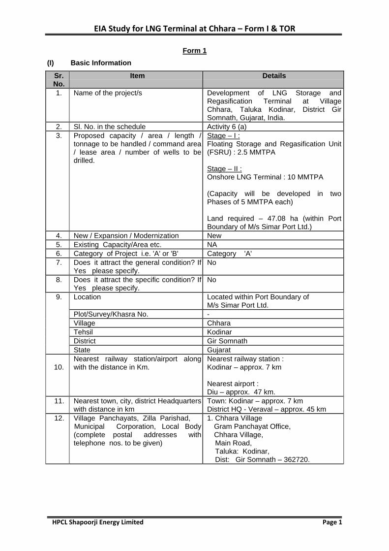
Form 1 (I) Basic Information
Sr. No.
Item Details
1. Name of the project/s Development of LNG Storage and Regasification Terminal at Village Chhara, Taluka Kodinar, District Gir Somnath, Gujarat, India.
2. Sl. No. in the schedule Activity 6 (a) 3. Proposed capacity / area / length /
tonnage to be handled / command area / lease area / number of wells to be drilled.
Stage – I : Floating Storage and Regasification Unit (FSRU) : 2.5 MMTPA Stage – II : Onshore LNG Terminal : 10 MMTPA (Capacity will be developed in two Phases of 5 MMTPA each) Land required – 47.08 ha (within Port Boundary of M/s Simar Port Ltd.)
4. New / Expansion / Modernization New 5. Existing Capacity/Area etc. NA 6. Category of Project i.e. 'A' or 'B' Category 'A' 7. Does it attract the general condition? If
Yes please specify. No
8. Does it attract the specific condition? If Yes please specify.
No
9. Location Located within Port Boundary of M/s Simar Port Ltd.
Plot/Survey/Khasra No. - Village Chhara Tehsil Kodinar District Gir Somnath State Gujarat
10.
Nearest railway station/airport along with the distance in Km.
Nearest railway station : Kodinar – approx. 7 km Nearest airport : Diu – approx. 47 km.
11. Nearest town, city, district Headquarters with distance in km
Town: Kodinar – approx. 7 km District HQ - Veraval – approx. 45 km
12. Village Panchayats, Zilla Parishad, Municipal Corporation, Local Body (complete postal addresses with telephone nos. to be given)
1. Chhara Village Gram Panchayat Office, Chhara Village, Main Road, Taluka: Kodinar, Dist: Gir Somnath – 362720.

EIA Study for LNG Terminal at Chhara – Form I & TOR
HPCL Shapoorji Energy Limited Page 2
Sr. No.
Item Details
2. Taluka Panchayat Office Govt. Hospital Road, Kodinar Town, Taluka: Kodinar, Dist: Gir Somnath – 362720. 3. Kodinar Municipal Corporation Govt.Hospital Road, Kodinar Town Taluka: Kodinar, Dist: Gir Somnath – 362720.
13. Name of the applicant HPCL Shapoorji Energy Limited 14. Registered Address B-210, ISCON Centre, 2nd Floor,
Shivranjani Cross Road, Opposite Deepkala Junction, Ahmedabad – 380 015
15. Address for correspondence : Name Designation (Owner/Partner/CEO) Address E-mail Telephone No. Fax No.
S. Mukundan Director SP Centre, 41/44, Minoo Desai Marg, Colaba, Mumbai 400 005 [email protected] 022 6749 0291 022 6749 0017
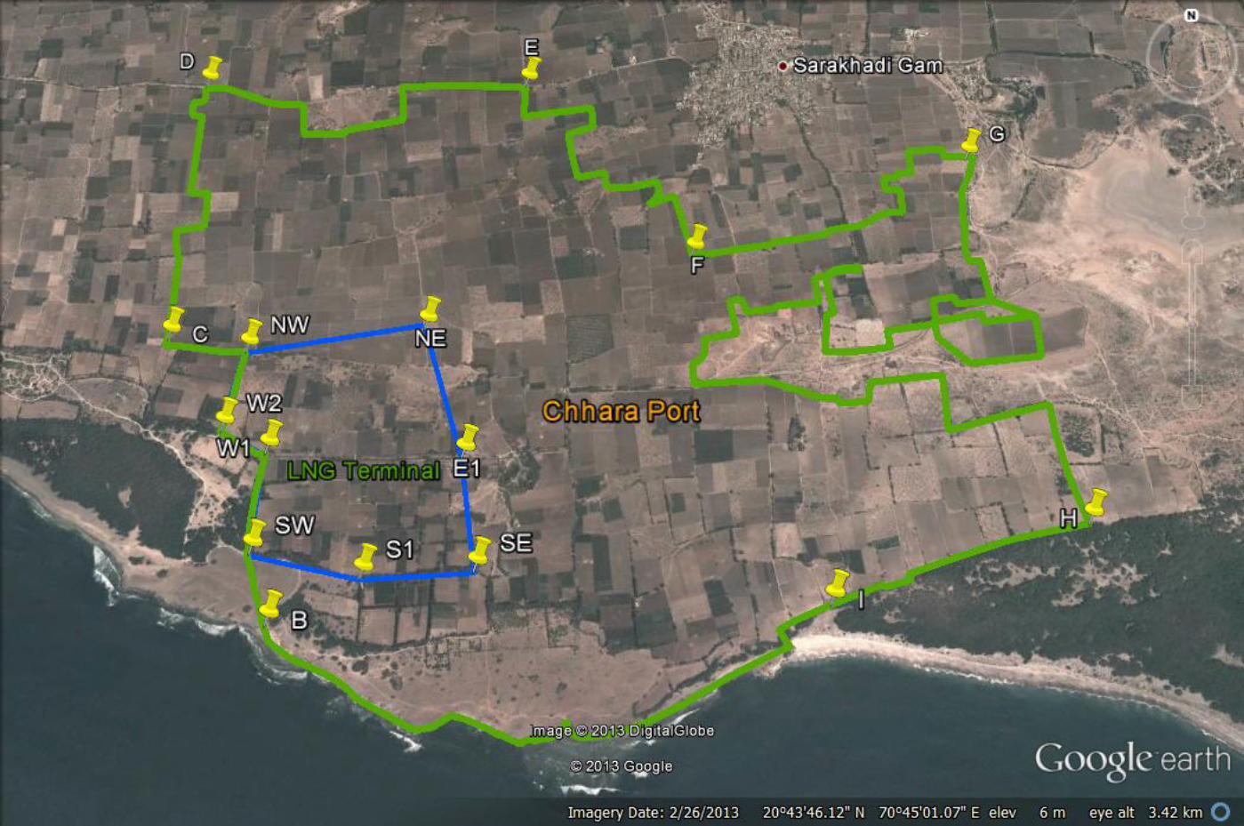
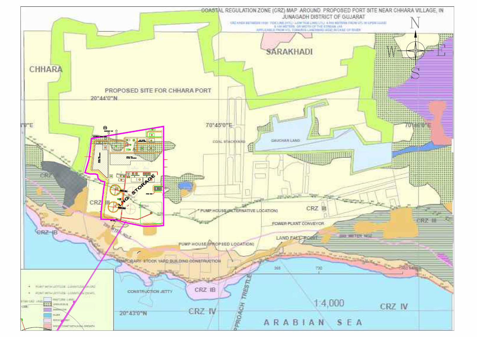
16. Details of Alternative Sites examined, if any. Location of these sites should be shown on a topo-sheet.
No. Proposed facilities to be located within Port Boundary of M/s Simar Port Ltd. Location of Project attached as enclosure – 1 Layout Plan attached as enclosure – 2.
17. Interlinked Projects Extension of Breakwater by M/s Simar Port Limited
18. Whether separate application of interlinked project has been submitted?
To be submitted
19. If Yes, date of submission To be submitted 20. If no, reason - 21. Whether the proposal involves
approval/ clearance under: if Yes, details of the same and their status to be given. (a) The Forest (Conservation) Act, 1980? (b) The Wildlife (Protection) Act, 1972? (c) The C.R.Z Notification, 1991?
No No Yes
22. Whether there is any Government order / policy relevant / relating to the site?
EC for Development of Port by M/s Simar Port Ltd. received on dt. 06th Jan, 14
23 Forest land involved (hectares) No
EIA Study for LNG Terminal at Chhara – Form I & TOR
HPCL Shapoorji Energy Limited Page 3
Sr. No.
Item Details
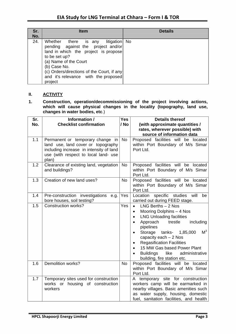
24. Whether there is any litigation pending against the project and/or land in which the project is propose to be set up? (a) Name of the Court (b) Case No. (c) Orders/directions of the Court, if any and it's relevance with the proposed project
No
II. ACTIVITY 1. Construction, operation/decommissioning of the project involving actions,
which will cause physical changes in the locality (topography, land use, changes in water bodies, etc.)
Sr. No.
Information / Checklist confirmation
Yes / No
Details thereof (with approximate quantities / rates, wherever possible) with
source of information data 1.1 Permanent or temporary change in
land use, land cover or topography including increase in intensity of land use (with respect to local land- use plan)
No Proposed facilities will be located within Port Boundary of M/s Simar Port Ltd.
1.2 Clearance of existing land, vegetation and buildings?
No Proposed facilities will be located within Port Boundary of M/s Simar Port Ltd.
1.3 Creation of new land uses? No Proposed facilities will be located within Port Boundary of M/s Simar Port Ltd.
1.4 Pre-construction investigations e.g. bore houses, soil testing?
Yes Location specific studies will be carried out during FEED stage.
1.5 Construction works? Yes • LNG Berths – 2 Nos • Mooring Dolphins – 4 Nos • LNG Unloading facilities • Approach trestle including
pipelines • Storage tanks- 1,85,000 M3
capacity each – 2 Nos • Regasification Facilities • 15 MW Gas based Power Plant • Buildings like administrative
building, fire station etc. 1.6 Demolition works? No Proposed facilities will be located
within Port Boundary of M/s Simar Port Ltd.
1.7 Temporary sites used for construction works or housing of construction workers
A temporary site for construction workers camp will be earmarked in nearby villages. Basic amenities such as water supply, housing, domestic fuel, sanitation facilities, and health

EIA Study for LNG Terminal at Chhara – Form I & TOR
HPCL Shapoorji Energy Limited Page 4
Sr. No.
Information / Checklist confirmation
Yes / No
Details thereof (with approximate quantities / rates, wherever possible) with
source of information data centre etc. for construction workers will be provided.
1.8 Above ground buildings, structures or earth works including linear structure, cut and fill or excavations
Yes Foundation and above ground construction work will be carried out for the project.
1.9 Underground works including mining or tunneling?
No No mining or tunneling.
1.10 Reclamation works? No NA 1.11 Dredging? No NA 1.12 Offshore structures? Yes Jetty, mooring structures and
approach trestle. 1.13 Production and manufacturing
processes? Yes Regasification of LNG.
1.14 Facilities for storage of goods or materials?
Yes Onshore LNG Storage Tanks (185,000 M3 capacity each) Phase I - 2 Nos. Phase II - 1 No.
1.15 Facilities for treatment or disposal of solid waste or liquid effluents?
Yes Municipal Solid Waste – Compost Plant Liquid Effluents – Treatment for recycle and reuse in green belt
1.16 Facilities for long term housing of operational workers?
Yes Long term housing of operational workers will be provided in Kodinar town.
1.17 New road, rail or sea traffic during construction or operation?
Yes Construction Phase Movement of construction equipment/material/manpower Operation Phase LNG Carriers
1.18 New road, rail, air waterborne or other transport infrastructure including new or altered routes and stations, ports airports etc.?
No Not envisaged.
1.19 Closure or diversion of existing transport routes or infrastructure leading to changes in traffic movements?
No Not envisaged.
1.20 New or diverted transmission lines or pipelines?
Yes LNG Pipeline – Berth to Onshore Terminal NG Pipeline – FSRU to Grid and LNG Terminal to Grid Internal Power Transmission lines and Utility pipe lines.
1.21 Impoundment, damming, culverting, realignment or other changes to the hydrology of watercourses or aquifers?
No -
1.22 Stream crossings? No - 1.23 Abstraction or transfer of water from
ground or surface water? No Sea water will be used in FSRU for
regasification

EIA Study for LNG Terminal at Chhara – Form I & TOR
HPCL Shapoorji Energy Limited Page 5
Sr. No.
Information / Checklist confirmation
Yes / No
Details thereof (with approximate quantities / rates, wherever possible) with
source of information data 1.24 Changes in water bodies or the land
surface affecting drainage or run-off?
No Not envisaged.
1.25 Transport of personnel or materials for construction, operation or decommissioning?
Yes Movement of construction equipment/material/manpower
1.26 Long-term dismantling or decommissioning or restoration works?
No FSRU will be moved out after commissioning of Onshore LNG Terminal. Natural Gas pipeline from FSRU to grid will be blinded.
1.27 Ongoing activity during decommissioning which could have an impact on the environment?
No Not envisaged.
1.28 Influx of people to an area either temporarily or permanently?
Yes Temporary influx due to workers during construction phase. Marginal influx due to operational personnel during operation phase.
1.29 Introduction of alien species? No Not envisaged. 1.30 Loss of native species or genetic
diversity? No Not envisaged.
1.31 Any other actions? No Not envisaged. 2. Use of Natural resources for construction or operation of the Project
(such as land, water, materials or energy, especially any resources that are non-renewable or in short supply)
Sr. No.
Information / Checklist Confirmation
Yes/ No
Details thereof (with approximate quantities /rates, wherever possible) with
source of information data 2.1 Land especially undeveloped or
agricultural land (ha) Yes Proposed facilities will be located
within Port Boundary of M/s Simar Port Ltd.
2.2 Water (expected source & competing users) unit: KLD
Yes Construction Phase – Fresh water requirement : 100 KLD Will be sourced from third party supplier. Operation Phase FSRU – 5,500 m3/hr Service water - 20 m3/hr Potable water - 3 m3/hr Fire water - 22,000 m3
2.3 Minerals (MT) No - 2.4 Construction material - stone,
aggregates, sand I soil (expected source - MT)
Yes Construction materials such as cement, steel, aggregate, etc. will be sourced from reputed manufacturer/suppliers.
2.5 Forests and timber (source - MT) No Not envisaged.

EIA Study for LNG Terminal at Chhara – Form I & TOR
HPCL Shapoorji Energy Limited Page 6
Sr. No.
Information / Checklist Confirmation
Yes/ No
Details thereof (with approximate quantities /rates, wherever possible) with
source of information data 2.6 Energy including electricity and fuels
(source, competing users) Unit: fuel (MT), energy (MW)
Yes From Gujarat State electric grid, 66kV power supply from Substation at Sarkhadi village approx. 10 km from Project site. Operation Phase Power Requirement – 15 MW
2.7 Any other natural resources (use appropriate standard units)
No Not envisaged
3. Use, storage, transport, handling or production of substances or materials, which could be harmful to human health or the environment or raise concerns about actual or perceived risks to human health
Sr. No.
Information/ Checklist confirmation
Yes/No
Details thereof (with approximate quantities /rates, wherever possible) with source of
information data 3.1 Use of substances or materials,
which are hazardous (as per MSIHC rules) to human health or the environment (flora, fauna and water supplies)
Yes LNG is inflammable liquid.
3.2 Changes in occurrence of disease or affect disease vectors (e.g. insect or water borne diseases)
No Not envisaged.
3.3 Affect the welfare of people e.g. by changing living conditions?
Yes LNG Terminal will improve socio-economic condition of the region as well as bring economic benefit to the people. It will also increase business and employment opportunity.
3.4 Vulnerable groups of people who could be affected by the project e.g. hospital patients, children the elderly etc.
No Not envisaged.
3.5 Any other causes No -
4. Production of solid wastes during construction or operation or decommissioning (MT/month)
Sr. No.
Information/ Checklist Confirmation
Yes/ No
Details thereof (with approximate quantities/rates, wherever possible) with source of
information data 4.1 Spoil, overburden or mine wastes No Not envisaged. 4.2 Municipal waste (domestic and or
commercial wastes) Yes During construction phase
insignificant amount of waste will be generated. During the operation phase, small

EIA Study for LNG Terminal at Chhara – Form I & TOR
HPCL Shapoorji Energy Limited Page 7
Sr. No.
Information/ Checklist Confirmation
Yes/ No
Details thereof (with approximate quantities/rates, wherever possible) with source of
information data amount of solid waste will be generated from administrative building, port user building and workshop.
4.3 Hazardous wastes (as per Hazardous Waste Management Rules)
Yes Insignificant quantities of hazardous waste (such as used oil) will be generated in both construction and operation phases. This will be managed as per Hazardous Waste Management Rules.
4.4 Other industrial process wastes No Not envisaged 4.5 Surplus product No Not envisaged 4.6 Sewage sludge or other sludge from
effluent treatment Yes Small amount of sewage sludge
generated will be treated in compost plant.
4.7 Construction or demolition wastes
Yes Construction waste will be properly segregated and utilized.
4.8 Redundant machinery or equipment No Not envisaged 4.9 Contaminated soils or other
materials No Not envisaged
4.10 Agricultural wastes No Not envisaged 4.11 Other solid wastes No Not envisaged
5. Release of pollutants or any hazardous, toxic or noxious substances to air
Sr. No. Information/Checklist confirmation Yes/ No
Details thereof (with approximate quantities /rates, wherever possible) with source of information data
5.1 Emissions from combustion of fossil fuels from stationary or mobile sources
Yes Emissions from power plant which will be using natural gas as fuel.
5.2 Emissions from production processes
No Not envisaged.
5.3 Emissions from materials handling including storage or transport
No Not envisaged.
5.4 Emissions from construction activities including plant and equipment
Yes Fugitive dust due to movement of vehicles Emissions from DG sets
5.5 Dust or odours from handling of materials including construction materials, sewage and waste
Yes Fugitive dust due to movement of vehicles.
5.6 Emissions from incineration of waste No Not envisaged. 5.7 Emissions from burning of
waste in open air (e.g. slash materials, construction debris)
No Not envisaged.
5.8 Emissions from any other sources Yes Flare during emergency gas leakages.
EIA Study for LNG Terminal at Chhara – Form I & TOR
HPCL Shapoorji Energy Limited Page 8
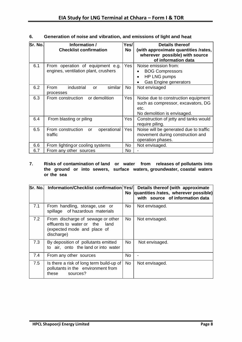
6. Generation of noise and vibration, and emissions of light and heat
Sr. No. Information / Checklist confirmation
Yes/ No
Details thereof (with approximate quantities /rates,
wherever possible) with source of information data
6.1 From operation of equipment e.g. engines, ventilation plant, crushers
Yes Noise emission from: • BOG Compressors • HP LNG pumps • Gas Engine generators
6.2 From industrial or similar processes
No Not envisaged
6.3 From construction or demolition Yes Noise due to construction equipment such as compressor, excavators, DG etc. No demolition is envisaged.
6.4 From blasting or piling Yes Construction of jetty and tanks would require piling.
6.5 From construction or operational traffic
Yes Noise will be generated due to traffic movement during construction and operation phases.
6.6 From lighting or cooling systems No Not envisaged. 6.7 From any other sources No -
7. Risks of contamination of land or water from releases of pollutants into the ground or into sewers, surface waters, groundwater, coastal waters or the sea
Sr. No. Information/Checklist confirmation Yes/ No
Details thereof (with approximate quantities /rates, wherever possible)
with source of information data
7.1 From handling, storage, use or spillage of hazardous materials
No Not envisaged.
7.2 From discharge of sewage or other effluents to water or the land (expected mode and place of discharge)
No Not envisaged.
7.3 By deposition of pollutants emitted to air, onto the land or into water
No Not envisaged.
7.4 From any other sources No -
7.5 Is there a risk of long term build-up of pollutants in the environment from these sources?
No Not envisaged.

EIA Study for LNG Terminal at Chhara – Form I & TOR
HPCL Shapoorji Energy Limited Page 9
8. Risk of accidents during construction or operation of the Project, which could affect human health or the environment
Sr. No. Information/ Checklist confirmation
Yes/ No
Details thereof (with approximate quantities/rates,
wherever possible) with source of information data
8.1 From explosions, spillages, fires etc. from storage, handling, use or production of hazardous substances
Yes Construction Phase – • Diesel storage Operation Phase – • Handling of LNG/NG • Storage of LNG
8.2 From any other causes No Not envisaged. 8.3 Could the project be affected by
natural disasters causing environmental damage (e.g. floods, earthquakes, landslides cloudburst etc)?
Yes Project located in Seismic Zone III- Moderate. No past record of cyclones at Kodinar coast.
9. Factors which should be considered (such as consequential development) which could lead to environmental effects or the potential for cumulative impacts with other existing or planned activities in the locality
Sr.No. Information/Checklist confirmation
Yes/ No
Details thereof (with approximate quantities /rates,
wherever possible) with source of information data
9.1 Lead to development of supporting utilities, ancillary development or development stimulated by the project which could have impact on the environment e.g. • Supporting infrastructure(roads,
power supply, waste or wastewater treatment etc)
• Housing development • Extractive industries • Supply industries • Other
Yes
Access road to the project site. Natural gas pipeline from project site to grid (will be developed by GSPL/GAIL). All supporting infrastructure will be developed within project site. Development of housing / extractive industries / supply industries not envisaged.
9.2 Lead to after-use of the site, which could have an impact on the environment
No Not envisaged.
9.3 Set a precedent for later developments
Yes Proposed project would facilitate growth of industrial/ commercial activities.
9.4 Have cumulative effects due to proximity to other existing or planned projects with similar effects
No Cumulative impacts, if any, will be identified and addressed in EIA.
EIA Study for LNG Terminal at Chhara – Form I & TOR
HPCL Shapoorji Energy Limited Page 10
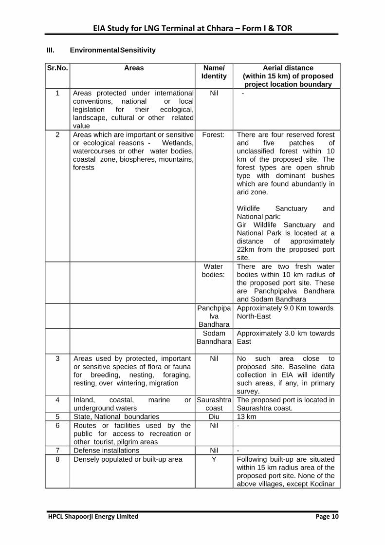
III. Environmental Sensitivity Sr.No. Areas Name/
Identity Aerial distance
(within 15 km) of proposed project location boundary
1 Areas protected under international conventions, national or local legislation for their ecological, landscape, cultural or other related value
Nil -
2 Areas which are important or sensitive or ecological reasons - Wetlands, watercourses or other water bodies, coastal zone, biospheres, mountains, forests
Forest:
There are four reserved forest and five patches of unclassified forest within 10 km of the proposed site. The forest types are open shrub type with dominant bushes which are found abundantly in arid zone. Wildlife Sanctuary and National park: Gir Wildlife Sanctuary and National Park is located at a distance of approximately 22km from the proposed port site.
Water bodies:
There are two fresh water bodies within 10 km radius of the proposed port site. These are Panchpipalva Bandhara and Sodam Bandhara
Panchpipalva
Bandhara
Approximately 9.0 Km towards North-East
Sodam Banndhara
Approximately 3.0 km towards East
3 Areas used by protected, important or sensitive species of flora or fauna for breeding, nesting, foraging, resting, over wintering, migration
Nil No such area close to proposed site. Baseline data collection in EIA will identify such areas, if any, in primary survey.
4 Inland, coastal, marine or underground waters
Saurashtra coast
The proposed port is located in Saurashtra coast.
5 State, National boundaries Diu 13 km 6 Routes or facilities used by the
public for access to recreation or other tourist, pilgrim areas
Nil -
7 Defense installations Nil - 8 Densely populated or built-up area Y Following built-up are situated
within 15 km radius area of the proposed port site. None of the above villages, except Kodinar

EIA Study for LNG Terminal at Chhara – Form I & TOR
HPCL Shapoorji Energy Limited Page 11
Sr.No. Areas Name/ Identity
Aerial distance (within 15 km) of proposed project location boundary
town is densely populated. Settlement Dist.
(km) Direction
Sarkhadi 2.4 NE
Chhara 3 W
Malsaram 5 NE
Damli 5.7 N
Kaj 5.7 NE
Kadodara 5.9 N
Pipli 6.3 NW
Pipalva Bavana
6.7 NE
Devli 7.4 NW
Panadar 7.7 NW
Nanavada 8 NE
Velan 8.6 E
Jantrakhadi 8.9 NE
Kodinar Town
9.1 NW
Dudana 9.8 N
Mul dwarka 9.9 W
Ronaj 10 N
Chauhan Ni khan
10.1 NW
Mitiyaj 10.4 N
Inchvadnani 11 N
Malgam 11 NE
Kotada 12.7 E
Vannakwada (in Diu)
13.3 E
9 Areas occupied by sensitive man-made land uses (hospitals/ schools/ places of worship/ community facilities)
Nil No areas occupied by sensitive man-made land uses within project site. Baseline data collection, in primary survey, will identify, such areas, if any.
10 Areas containing important, high quality or scarce resources, (ground water resources/ surface resources/ forestry, agriculture/ fisheries, tourism minerals)
Nil No area containing important, high quality or scarce resources within project site. Baseline data collection, in primary survey, will identify, such areas, if any
11 Areas already subjected to pollution or environmental damage. (those where existing legal environmental standards are exceeded)
Nil Negligible industrial / commercial activities in the study region.
12 Areas susceptible to natural hazard which could cause the project to present environmental problems, (earthquakes/ subsidence, landslides/
Saurashtra Coast
The project area is located in the moderately active seismic region. Saurashtra coast at Kodinar has

EIA Study for LNG Terminal at Chhara – Form I & TOR
HPCL Shapoorji Energy Limited Page 12
Sr.No. Areas Name/ Identity
Aerial distance (within 15 km) of proposed project location boundary
erosion or extreme or adverse climatic conditions)
been identified as area subjected to low erosion.
EIA Study for LNG Terminal at Chhara – Form I & TOR
HPCL Shapoorji Energy Limited Page 13
Proposed Terms of Reference for EIA Study
Objectives
i. Collection of primary data supported by secondary data in the study area for assessment of baseline quality of marine environment including water, sediment and biological components and secondary data from state/local departments
ii. Collection of existing hydrography data supported by secondary data already collected in offshore region in the vicinity of the project site during pre-monsoon and post-monsoon seasons
iii. Assessment of the present status of air, noise, water, land, biological and socio-economic components of environment including parameters of human interest up to 10 km radial distance from the proposed site
iv. Identification of potential impacts on various environmental components due to activities envisaged during construction and operational phases of the proposed project
v. Prediction of impacts on the various environmental components using appropriate mathematical / simulation models
vi. Preparation of environmental impact statement based on the identification, prediction and evaluation of impacts
vii. Delineation of Environmental Management Plan (EMP) outlining preventive and control strategies for minimising adverse impacts during construction and operational stages of the proposed project along with the cost and time-schedule for implementation of EMP
viii. Formulation of environmental quality monitoring programmes for construction and operational phases as per the requirements of statutory authorities
ix. Assessment of proposed terminal site based on coastal zone regulation for obtaining clearance from Gujarat Coastal Zone Management Authority (GCZMA)
x. Presentation of draft EIA in Public Hearing to be conducted for the project as per the EIA Notification 2006 and the compliance of the issues raised by the public and incorporation in the EIA-EMP report.
Activities for each Environmental Component
The details of work plan under individual environment components are as follows:
Air Environment
• Design of ambient air quality network based on prevailing meteorology and location of sensitive receptors.
• Assessment of existing levels of various air pollutants listed in NAAQS at 5 monitoring locations as per CPCB Guidelines (National Ambient Air Quality Monitoring Series : NAAQMS/ ... /2003-04, Table 4.1 and Section 4.2.4)
• Collection of meteorological data, viz. wind speed, wind direction, relative humidity, temperature, lapse rate and cloud cover by installing weather station at the site.
EIA Study for LNG Terminal at Chhara – Form I & TOR
HPCL Shapoorji Energy Limited Page 14
• Inventory of point, line and area sources of air pollution and quantification of emission in proposed project.
• Estimation of air emissions including fugitive emissions from the proposed project activities
• Evaluation of atmospheric emissions and prediction of Ground Level Concentrations of air pollutants (PM, SO2 & NOx) through appropriate air quality models incorporating the requirements specified in the publication of Central Pollution Control Board “Assessment of Impact to Air Environment: Guidelines for conducting Air Quality Modelling”
• Assessment of anticipated changes in air quality and suggestions on mitigation measures
• Evaluation of the adequacy of the proposed pollution control measures to meet air quality emission standards.
Noise Environment
• Measurement of noise levels in residential/ commercial/sensitive zones in the study area.
• Monitoring of noise levels due to stationary and vehicular sources near major roads/junctions in area within 1 km of the project site.
• Studies on existing traffic movement and impact of proposed activities on existing transportation system within 1 km of the project site. Keeping in view the increase in traffic movement, assessment of additional facilities to be created and suggestions on safety measures to be followed.
• Prediction and evaluation of impacts due to increase in noise levels arising out of the proposed project on the surrounding environment.
• Identification of high level noise zones requiring mitigation measures within project site.
• Evaluation of existing and proposed noise pollution control measures.
• Recommendations on mitigation measures for noise pollution
Inland Water Environment
• Study of existing five ground and five surface water sources in study area with respect to quantity and quality (physico-chemical, biological and bacteriological characterization)
• Impact of project operations on water demand of other users.
• Assessment of wastewater quality and quantity to be discharged from the proposed project
• Study of existing drainage pattern and impact of the project on the drainage pattern.
• Evaluation of proposed wastewater treatment systems.
• Recommendations on water conservation measures
EIA Study for LNG Terminal at Chhara – Form I & TOR
HPCL Shapoorji Energy Limited Page 15
• Assessment of feasibility of water recycle and reuse for green belt development and irrigation
Marine Environment
• Assessment of marine water quality in project impact zone for physical, chemical, and biological parameters including planktons and primary productivity
• Assessment of sediment quality in terms of texture, particle size distribution organic pollutants and heavy metals
• Assessment of sediment quality for biotic parameters such as benthos (micro and micro fauna)
• Assessment of mangrove forests/vegetation in the coastal and inter tidal zone
• Study the discharges, if any, during LNG operations
• Bathymetric study to assess tranquility conditions at the proposed site
• Impact on shore line changes along the stretch and suggestion on erosion prevention measures in the area
• Delineation of environmental management plan including post project monitoring
• Suggestion on contingency plan, taking into account the accident scenario and natural disasters
• Study of project site details from coastal zone regulation point of view for clearance from Gujarat Coastal Zone Management Authority (GCZMA)
Land Environment
• Study of layout plan in the proposed site
• Study of existing landuse and cropping patterns, vegetation, forestry, wastelands Studies on soil characteristics in the study area
• Characterization of solid wastes likely to be generated and its safe disposal
• Assessment of impact of the project on the existing habitation and infrastructure, if any
• Impact of construction activities on the shore line and the terrestrial environment
• Delineation of options for solid and hazardous waste management
• Design of green belt and identification of suitable native plant species for the proposed green belt
Terrestrial Biological Environment
• Collection of information about flora and fauna and determination of species diversity, density, abundance etc.
• Identification of rare and endangered species in the study area
• Assessment of impacts on terrestrial flora and fauna due to air emissions
EIA Study for LNG Terminal at Chhara – Form I & TOR
HPCL Shapoorji Energy Limited Page 16
• Delineation of measures for abatement/reduction of impact on biological environment
Socio-economic and Health Environment
• Collection of baseline data related to socio-economic profile of the study area with reference to :
- Stakeholders relevant to the Project
- Human settlements, male/female ratio, occupational pattern, employment and income
- Infrastructure resource base, viz. medical, education, water resources, power supply
- Economic resource base, viz. agriculture, industries, forest, trade and commerce
- Health Status, viz. morbidity pattern with reference to prominent and endemic diseases
- Cultural and Aesthetic attributes in the study area including places of historical/ archaeological importance
• Assessment of economic benefits to community and environment due to existing and proposed developmental activities
• Socio-economic survey to assess the Quality of Life of the people in the study area and their perceptions about the projects
• Projection of anticipated changes due to the proposed project, and delineation of measures to minimize the impacts.
• Assessment of impacts on places of historical/archaeological importance and aesthetic impairment, if any.
• Assessment of economic benefits to community and environment due to the proposed projects.
• Delineation of regional socio-economic environment management plan through initiation of beneficial activities (welfare) for local communities providing financial support.
• Assessment of impacts due to the proposed activities on fishing and suggestion of management plan and provision to be made under Corporate Social Responsibility (CSR).
Environmental Management Plan
• Delineation of Environmental Management Plan (EMP) separately for the construction and operational phase after identifying, predicting and evaluating the impacts on each component of the environment with a view to maximising the benefits from the project.
EIA Study for LNG Terminal at Chhara – Form I & TOR
HPCL Shapoorji Energy Limited Page 17
• Delineation of post-project environmental monitoring plan with identified parameters and associated cost
• Incorporation of safety aspects associated with the proposed activity/facilities.
Risk Assessment Studies
Scope of Work
Preparation of Risk Assessment (RA) report based on hazard identification, hazard quantification with recourse to Maximum Credible Accident (MCA) Analysis and recommending risk mitigation measures and disaster management plan. Risk assessment would cover LNG handling and storage facilities in FSRU & Land Terminal.
Objectives of Study
The objectives of the Risk Assessment study are as follows:
• Hazard identification through computation of hazard indices and inventory analysis
• Generation of scenarios for accidental release of flammable chemicals
• Computation of damage distances based on consequence analysis for credible and worst case scenarios
• Assessment of risk and delineation of risk mitigation measures
• Preparation of emergency evacuation and Disaster Management Plan
Work Plan
Hazard Identification
• Collection of relevant information for the proposed development facilities
• Identification of hazard prone operations based on credible and worst case accidental release scenarios.
• Delineation of vulnerable operations
Hazard Assessment and Evaluation
Hazard prone operations would be critically examined with recourse to Maximum Credible Accident (MCA) analysis in order to arrive at hazards posed to the facilities and risk posed to the personnel on work place. The techniques proposed to be used are:
• Consequence Analysis: The damage distances will be computed due to accidental release of flammable chemicals causing pool fires, flash fires, jet fires and dispersion upto lower flammability limit. The extent of damage for 1% lethality and first degree burns will be assessed by plotting the damage distances on area maps
• Individual Risk Curves: The risk posed to the personnel working on critical zones (accident prone) will be computed by collecting data on probability values for identified failures scenarios.

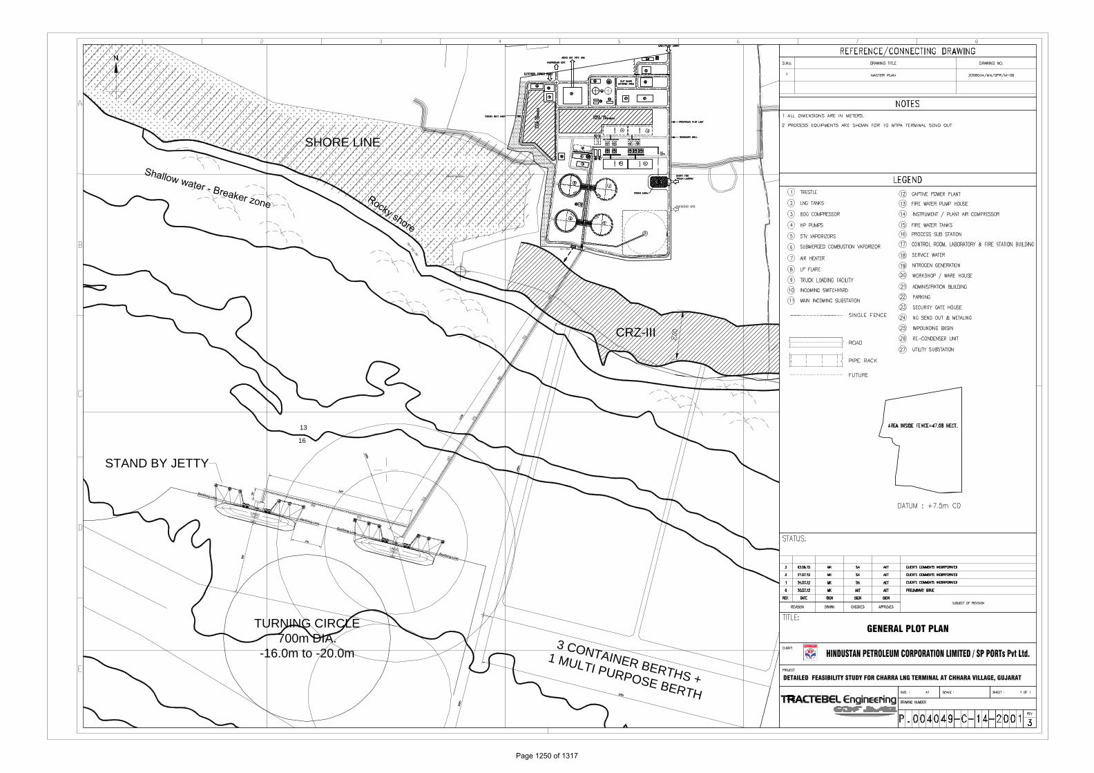
SHORE LINE
TURNING CIRCLE700m DIA.
-16.0m to -20.0m3 CONTAINER BERTHS +
1 MULTI PURPOSE BERTH
STAND BY JETTY
CANALCANAL
CANAL
CAR
T TRAC
KC
ART TR
ACK
13
16
CRZ-III
2.5
MTP
A
2.5
MTP
A
2.5 MTP
A
2.5 MTP
A
2.5
MTP
A
2.5
MTP
A
2.5 MTP
A
2.5 MTP
A
2.5
MTP
A
2.5
MTP
A
2.5 MTP
A
2.5 MTP
A
GENERAL PLOT PLAN
DETAILED FEASIBILITY STUDY FOR CHARRA LNG TERMINAL AT CHHARA VILLAGE, GUJARAT
Page 1250 of 1317

EXECUTIVE SUMMARY
P.004049
G 97
5001
HINDUSTAN PETROLEUM CORPORATION LTD. / SP PORTS PVT. LTD.
DETAILED FEASIBILITY REPORT FOR CHHARA LNG PROJECT
EXECUTIVE SUMMARY
4 21.1.13 Final AKT RM CZ
3 26.12.12 Fourth Issue AKT RM CZ
2 21.11.12 Third Issue AKT RM CZ
1 14.09.12 Second Issue AKT RM CZ
0 10.09.12 First Issue AKT RM CZ
Rev. Date Subject of revision Author Checked Approved

EXECUTIVE SUMMARY
P.004049
G 97
5001
Rev.4 – 21.1.13 DFR FOR CHHARA LNG TERMINAL Page 1 of 1
TABLE OF CONTENTS
1.0 INTRODUCTION ...................................................................................................... 1
2.0 OBJECTIVES ............................................................................................................ 1
3.0 ASSUMPTIONS ........................................................................................................ 1
4.0 FINDINGS ................................................................................................................ 2
4.1 Terminal Layout ............................................................................................... 2
4.2 Terminal Facilities ............................................................................................ 3
4.3 Project Schedule .............................................................................................. 4
4.4 Project Cost Estimation ................................................................................... 4
5 CONCLUSIONS ........................................................................................................ 5
EXECUTIVE SUMMARY
P.004049
G 97
5001
Rev.4 – 21.1.13 DFR FOR CHHARA LNG TERMINAL Page 1 of 5
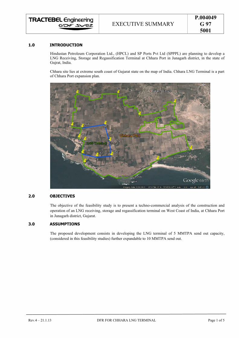
1.0 INTRODUCTION
Hindustan Petroleum Corporation Ltd., (HPCL) and SP Ports Pvt Ltd (SPPPL) are planning to develop a LNG Receiving, Storage and Regassification Terminal at Chhara Port in Junagarh district, in the state of Gujrat, India. Chhara site lies at extreme south coast of Gujarat state on the map of India. Chhara LNG Terminal is a part of Chhara Port expansion plan.
2.0 OBJECTIVES
The objective of the feasibility study is to present a techno-commercial analysis of the construction and
operation of an LNG receiving, storage and regassification terminal on West Coast of India, at Chhara Port
in Junagarh district, Gujarat.
3.0 ASSUMPTIONS
The proposed development consists in developing the LNG terminal of 5 MMTPA send out capacity,
(considered in this feasibility studies) further expandable to 10 MMTPA send out.

EXECUTIVE SUMMARY
P.004049
G 97
5001
Rev.4 – 21.1.13 DFR FOR CHHARA LNG TERMINAL Page 2 of 5
4.0 FINDINGS
4.1 Terminal Layout
Following Layout is the basis of Feasibility studies for development of LNG terminal at proposed Chhara Port:

EXECUTIVE SUMMARY
P.004049
G 97
5001
Rev.4 – 21.1.13 DFR FOR CHHARA LNG TERMINAL Page 3 of 5
4.2 Terminal Facilities
The LNG Regassification Terminal is including all facilities related to :
a) The ship Unloading : - 1 berthing facility with provision of standby jetty for future
- 1 Arm Station
- 1 Local substation
and associated piping and instrumentation.
b) The LNG Storage:
- 2 LNG Tanks
- 3 transfer pumps per tank (Plus one spare pump well)
- 2 monorails per tank
and associated piping and instrumentation
c) The LNG transfer and vaporization
- 1 Absorber
- 4 HP LNG Pumps
- 4 Shell and Tube LNG Vaporizers with Air Heaters
- 2 Submerged Combustion LNG Vaporizers
and associated equipment, piping and instrumentation
d) The gas sendout and metering
- Metering facilities comprising of filter and turbine flow meter
- Pig launching facilities at Terminal
- Pipeline connecting Terminal to nearest Gas grid
- Pig receiving facilities at Receiving terminal (connecting Gas grid)
and associated equipment, piping and instrumentation
e) The Boil off handling and flaring:
- 3 Boil Off Gas Compressors
- 2 KO Drums
- 2 Drainage drums
- 1 flare stack
and associated equipment, piping and instrumentation
f) The utilities production for:
- Instrument Air and Plant Air
- Service water
- Gaseous Nitrogen production
with all associated equipment, piping and instrumentation
g) The Power distribution
- Power from State grid
- 2 Gas engine generators
- 1 Emergency Diesel generator
- 1 Main substation and 3 other substations
with required MCC’s.

EXECUTIVE SUMMARY
P.004049
G 97
5001
Rev.4 – 21.1.13 DFR FOR CHHARA LNG TERMINAL Page 4 of 5
4.3 Project Schedule
The estimated schedule of the project is 54 months from the date of project approval by HPCL/SP Ports Pvt
Ltd.
The EPC contract schedule being 42 months.
4.4 Project Cost Estimation
Estimated capital cost of the project for a send out capacity of 5 MMTPA is as below:
Description Unit Value
Capital Cost (without interest during construction (IDC)) Rs. Crores 4,796.85
Interest During Construction (IDC)) Rs. Crores 611.97
Capital Cost (with interest during construction (IDC)) Rs. Crores 5,408.82
EXECUTIVE SUMMARY
P.004049
G 97
5001
Rev.4 – 21.1.13 DFR FOR CHHARA LNG TERMINAL Page 5 of 5
5 CONCLUSIONS
Based on the above analyses the following can be concluded:
Chhara Port offers suitable conditions for an LNG Terminal to be built.
Chhara LNG Terminal will be an important addition to India’s energy infrastructure and help establish security of gas supply for Power plants and other business users.
Based on the above the following is recommended:
HPCL / SP Ports Pvt Ltd should finalize FEED / EPC bid package.
Additional Soil Investigations should be carried out prior to / during FEED studies.
HPCL/SP Ports Pvt Ltd should start discussions with Pipeline transmissions companies and finalize an MOU for RLNG evacuation.
FEASIBILITY REPORT
P.004049
G 97
5002
HINDUSTAN PETROLEUM CORPORATION LTD. / SP PORTS PVT. LTD.
DETAILED FEASIBILITY REPORT FOR CHHARA LNG PROJECT
FEASIBILITY REPORT
4 26.12.2012 Final AKT RM CZ
3 19.11.2012 Client Comments incorporated AKT RM CZ
2 20.09.2012 Project Opex revised AKT RM CZ
1 14.09.2012 Second Issue AKT RM CZ
0 10.09.2012 First Issue AKT RM CZ
Rev. Date Subject of revision Author Checked Approved

FEASIBILITY REPORT
P.004049
G 97
5002
Rev.4 – 26.12.12 DFR FOR CHHARA LNG TERMINAL Page 1 of 1
TABLE OF CONTENTS
1.0 PURPOSE ................................................................................................................. 1
2.0 INTRODUCTION ...................................................................................................... 1
3.0 PORT FACILITIES .................................................................................................... 4
4.0 SITE SELECTION ...................................................................................................... 5
5.0 DESIGN BASIS ......................................................................................................... 5
6.0 OPTIMIZATION STUDY AND RECOMMENDED FACILITIES IN LNG TERMINAL ...... 7
7.0 LNG UNLOADING FACILITIES AT THE PORT / MARINE FACILITIES ...................... 8
8.0 MARINE FACILITIES ............................................................................................... 8
9.0 ONSHORE FACILITIES ............................................................................................. 9
10.0 RLNG EVACUATION PLAN .............................................................................. 10
11.0 PROJECT IMPLIMENTATION SCHEDULE ........................................................ 10
12.0 CAPEX / OPEX ................................................................................................ 11
13.0 POLLUTION CONTROL MEASURES ................................................................. 11
14.0 SAFETY MEASURES ........................................................................................ 12
15.0 PROVISION FOR FUTURE EXPANSION .......................................................... 14
16.0 LIST OF EXCLUSIONS FROM FEASIBILITY REPORT AND FURTHER STUDIES / WORK TO BE CARRIED OUT .................................................................................. 14
17.0 CONCLUSIONS AND RECOMMENDATIONS .................................................... 14

FEASIBILITY REPORT
P.004049
G 97
5002
Rev.4 – 26.12.12 DFR FOR CHHARA LNG TERMINAL Page 1 of 18
1.0 PURPOSE
The aim of this Detailed feasibility report is to define proposed LNG Import, storage and regassification Terminal main characteristics as well as to assess the technical feasibility and financial viability of the project.
This report includes:
Brief about HPCL / SPPPL
Available infrastructure and Port future plans
Port facilities
Site selection report
Design basis
Optimization studies and recommended facilities in the LNG Terminal
LNG unloading facilities at the Port
Marine facilities
Onshore facilities
RLNG Evacuation plan
Project Implementation schedule
Capex / Opex
Requirement of working capital
Phasing of expenditure yearwise
Pollution control measures
Safety measures
Financial analysis
Provision for future expansion
Details on maximization of Rupee cost
List of exclusions from Detailed feasibility study and further studies recommended / work to be done
Conclusions and recommendations
2.0 INTRODUCTION
2.1. Background
Simar Port Ltd, a Shapoorji Pallonji Group company is developing a deep draft, all weather multipurpose
port on BOOT basis under concession from Govt. of Gujarat at Chhara, Junagarh district Gujarat.
Hindustan Petroleum Corporation Ltd (HPCL) along with SP Ports Pvt Ltd (SPPPL) are desirous of undertaking Detailed Feasibility Study for establishing technical and commercial viability of setting up a LNG Import and regasification Terminal of 5 MMTPA capacity at the port of Chhara, district Junagarh, Gujarat.
FEASIBILITY REPORT
P.004049
G 97
5002
Rev.4 – 26.12.12 DFR FOR CHHARA LNG TERMINAL Page 2 of 18
2.2. Brief about HPCL
HPCL is a Government of India Enterprise with a Navratna Status, and a Fortune 500 and Forbes 2000 company, with an annual turnover of Rs. 1,32,670 Crores and sales/income from operations of Rs 1,43,396 Crores (US$ 31,546 Millions) during FY 2010-11, having about 20% Marketing share in India among PSUs and a strong market infrastructure.
HPCL operates 2 major refineries producing a wide variety of petroleum fuels & specialties, one in Mumbai
(West Coast) of 6.5 Million Metric Tonnes Per Annum (MMTPA) capacity and the other in Vishakapatnam,
(East Coast) with a capacity of 8.3 MMTPA. HPCL holds an equity stake of 16.95% in Mangalore Refinery
& Petrochemicals Limited, a state-of-the-art refinery at Mangalore with a capacity of 9 MMTPA. In
addition, HPCL is constructing a 9 MMTPA refinery at Bathinda, in the state of Punjab, as a JV with Mittal
Energy Investments Pte Ltd.
HPCL also owns and operates the largest Lube Refinery in the India producing Lube Base Oils of
international standards, with a capacity of 335 TMT. This Lube Refinery accounts for over 40% of the
India's total Lube Base Oil production.
HPCL's vast marketing network consists of 13 Zonal offices in major cities and 101 Regional Offices
facilitated by a Supply & Distribution infrastructure comprising Terminals, Pipeline networks, Aviation
Service Stations, LPG Bottling Plants, Inland Relay Depots & Retail Outlets, Lube and LPG
Distributorships. HPCL, over the years, has moved from strength to strength on all fronts. The refining
capacity steadily increased from 5.5 MMTPA in 1984/85 to 14.8 MMTPA presently. On the financial front,
the turnover has grown from Rs. 2687 Crores in 1984-85 to Rs 1,32,670 Crores in FY 2010-11.
2.3. Brief about SP Group
The Shapoorji Pallonji Group is an enterprise which draws vital support from its various individual entities to be able to execute turnkey projects, swiftly and efficiently. Along with the flagship company Shapoorji Pallonji & Company Limited (specializing in Construction, Design & Build and EPC), the other luminaries give the SP Group its strength and capability.
Today, with over 23,000 employees and a group turnover of US$ 2.5 Bn, Shapoorji Pallonji Group has evolved and grown exponentially to become a huge conglomerate with multiple business segments with a progressive outlook and a thoroughly professional approach. The Group today has a strong presence in India and internationally including the Middle East and Africa. (With a rich legacy of 147 years and a consistently superior track record, the Shapoorji Pallonji Group remains committed towards excellence in each domain of its operations). SP group’s business interests cover construction (including residential, commercial, industrial and infrastructure), real estate, infrastructure (comprising coal mining, power, ports and roads), biofuels and agriculture, consumer products, electro-mechanical and MEP services, facades and interiors, engineering, textiles, business automation and shipping and logistics.
2.4. Details of Proposed Chhara Port
2.4.1. Port Location
Proposed Port is located near village Chhara located approximately at Latitude -20°43’19” N and Longitude -70°44’28” in the Kodinar Taluka Junagarh district of Gujarat state.
The shoreline is on the South face of the area stretching for a length of 2.5km. Kodinar is the nearest town and connected to the railway network. Chhara port is proposed to be all weather, multipurpose port with water depths available upto -20m CD. Nearest National Highway is NH 8E which is approximately 6.5 km on the north of proposed port site.
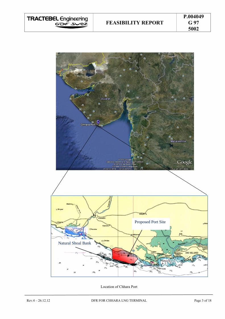
Location of Chhara port is shown on Google map as below:
FEASIBILITY REPORT
P.004049
G 97
5002
Rev.4 – 26.12.12 DFR FOR CHHARA LNG TERMINAL Page 3 of 18
Location of Chhara Port
Natural Shoal Bank
Proposed Port Site

FEASIBILITY REPORT
P.004049
G 97
5002
Rev.4 – 26.12.12 DFR FOR CHHARA LNG TERMINAL Page 4 of 18
3.0 PORT FACILITIES
3.1. Proposed Berths
Chhara Port is planned to be developed in 2 phases with following Berth availabilities:
Cargo Phase 1 Phase 2
Coal 1 2
Bulk Jetty 1
Containers 3
Multipurpose Berth 1
LNG Jetty 1 + 1 (standby)
3.2. Nautical Infrastructure
As per Port master plan, nautical infrastructure details are as follows:
The proposed approach channel is about 6.5 km long to reach offshore deepwater. The width of approach channel is expected to be 300m.
Turning basin diameter of 600m and depth of -20.0m CD.
The proposed Breakwater will be approximately 4.5 km long on the natural shoal bank (including extension of 1.25 km for providing tranquillity conditions for LNG jetty).
3.3. Port services
Simar Port Ltd would be providing safe, tranquil conditions for harbouring LNG vessels. Simar Port
Limited will provide all necessary services associated with the safe transit and mooring of the LNG carriers
that will unload the LNG at the terminal.
FEASIBILITY REPORT
P.004049
G 97
5002
Rev.4 – 26.12.12 DFR FOR CHHARA LNG TERMINAL Page 5 of 18
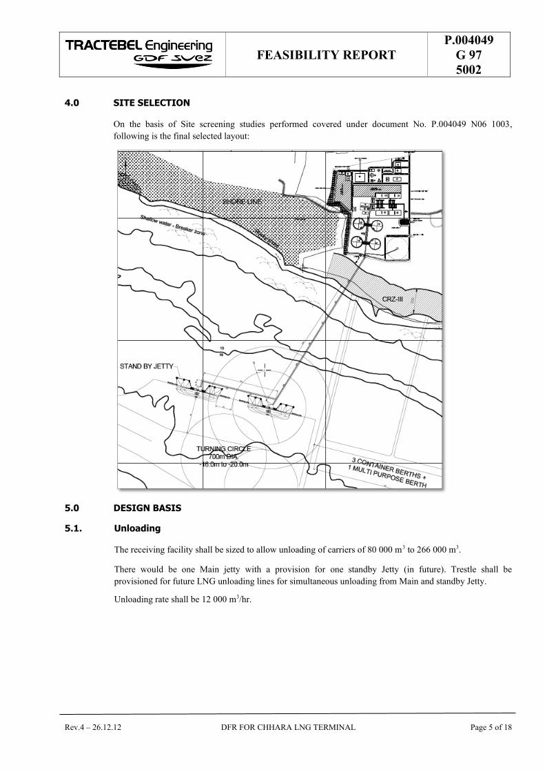
4.0 SITE SELECTION
On the basis of Site screening studies performed covered under document No. P.004049 N06 1003,
following is the final selected layout:
5.0 DESIGN BASIS
5.1. Unloading
The receiving facility shall be sized to allow unloading of carriers of 80 000 m3 to 266 000 m3.
There would be one Main jetty with a provision for one standby Jetty (in future). Trestle shall be
provisioned for future LNG unloading lines for simultaneous unloading from Main and standby Jetty.
Unloading rate shall be 12 000 m3/hr.

FEASIBILITY REPORT
P.004049
G 97
5002
Rev.4 – 26.12.12 DFR FOR CHHARA LNG TERMINAL Page 6 of 18
5.2. LNG Characteristics
As Terminal is planned on the basis LNG supply through the Spot market, LNG characteristics will vary in
a wide range. For this feasibility study, the heaviest and leanest compositions were considered as tabulated
below:
Description Unit
Rich Gas Lean Gas
Methane C1 mole %
86.98 97.21
Ethane C2 mole %
9.08 2.49
Propane C3 mole %
2.53 0.14
I-Butane iC4 mole %
0.42 0.09
N-Butane nC4 mole %
0.62 0.02
I-Pentane iC5 mole %
0.00 0.00
N-Pentane nC5 mole %
0.00 0.03
Hexane C6+ mole %
0.00 0.00
Nitrogen N2 mole %
0.37 0.02
Carbon CO2 mole %
0.00 0.00
Oxygen mole %
0.00 0.00
Total mole %
100.00 100.00
Heating Value BTU / Kg.
51 382 52 447
GHV Volume (BTU/SCF)
1 137 1 034
LHV Kcal/Kg
11 704 11 906
Density Kg / CBM
460.3 428.83
Mol. Weight
18.50 16.49
Temperature(-) TL(oC)
159.6 159.4
5.1. Send Out
Send out pressure :
o Design : 98 bar o Nominal : 95 bar o Minimum : 50 bar
Send out rates :
Average On yearly basis 5 MMTPA
Peak 125% Average
5.2. Gas Characteristics
Gas characteristics will be according to Indian standard, OISD–STD–194 and Gujarat grid specifications
5.3. Performances to be guaranteed
The Plant performances will be guaranteed in order to maintain the required sendout and availability for
both LNG importation and gas send-out.
FEASIBILITY REPORT
P.004049
G 97
5002
Rev.4 – 26.12.12 DFR FOR CHHARA LNG TERMINAL Page 7 of 18
6.0 OPTIMIZATION STUDY AND RECOMMENDED FACILITIES IN LNG TERMINAL
6.1. LNG Storage Capacity Optimization
Storage capacity optimization confirms the optimized tank capacity to be 2 X 185,000 m3 (Net).
This is represented by document “Ship and tank optimization” document no. P.004049 P05 0013.
6.2. LNG Storage Tanks Type Selection
Following four different types of LNG storage tanks have been compared :
1. Single containment tank, self supporting type (SCT); 2. Double containment tank, self supporting type (DCT); 3. Full containment tank, self supporting type, with concrete roof (FCT); 4. Membrane tank with concrete roof (MT).
Based on the comparison studies, self-supporting, full containment tank with concrete roof (FCT) has been selected as the safest and most optimum solution.
This is represented in the document “LNG Storage Tanks Type Selection” – document no. P.004049 P21 0012.
6.3. LNG Vaporizers type selection
Various options for Vaporization have been considered for Chhara LNG Terminal:
Heat source: fuel gas
Submerged combustion vaporizers (SCV)
Heat source: seawater
Open rack vaporizers (ORV) Intermediate fluid vaporizers (IFV)
Heat source: ambient air
Ambient air vaporizers (AAV) Shell & tubes vaporizer combined with air heater
Based on the optimization studies covered under Optimized scheme and Estimated utility consumption, STV/air heaters supplemented by SCV for cold weather conditions are selected. Refer document No. P.004049 P08 0002
6.4. Power Source Optimization
An optimization study is carried out to select the power source, and following 3 options were considered:
Power supply from 66 KV Gujarat State Electricity grid and Gas Engine generators on standby
Captive Power plant fed by Gas Engine generator and State Electricity grid power standby
Captive Power plant fed by Gas turbine generator and State electricity grid power standby.
Based on the Optimization studies, grid power with backup from gas engine generators are considered as
most optimum.
Refer document “Power Source Optimization” – document no. P.004049 E70 0453.
FEASIBILITY REPORT
P.004049
G 97
5002
Rev.4 – 26.12.12 DFR FOR CHHARA LNG TERMINAL Page 8 of 18
7.0 LNG UNLOADING FACILITIES AT THE PORT / MARINE FACILITIES
7.1.1. Ship Berthing / Arm connection
LNG will be delivered by LNG ships in the range of 80,000 to 266,000m3 capacity. At ship arrival, the berthing and mooring manoeuvers will be managed by the port pilot with the assistance of pilots, tug boats and ship berthing monitoring system installed at the jetty which is connected to the master control room.
When the ship is safely moored and the communications from ship and shore are established, the vapour return arm and the LNG unloading arms will be connected. Subsequently cool down of the ship’s transfer piping and the LNG unloading arms will be started with a small LNG flow from the ship after the confirmation of Emergency Shutdown System test.
7.1.2. Ship Unloading
LNG will be unloaded by the ship unloading pumps. The LNG discharged from the LNG ship will flow via unloading arms to either or both the LNG storage tanks.
Three identical LNG Unloading Arms, each equipped with Powered Emergency Release Coupler (PERC) and Quick Connect/Disconnect Coupler (QCDC) for LNG unloading to the storage tank will be used to achieve the design ship unloading rate of 12,000 m³/h.
A Vapour Return Arm will be used to return some of the displaced gas from the LNG storage tanks back to the LNG ship by operating the Ship Return Gas Blower.
The flow rates into each LNG storage tank are adjusted by control valves installed on the tank’s unloading line.
A part of BOG generated during unloading operation is returned to the cargo tanks of the LNG ship.
8.0 MARINE FACILITIES
8.1. Jetty Head
The jetty head will accommodate berthing of the LNGC and will be fit with equipment and systems that will allow safe and efficient operation works:
• The berthing dolphins with fenders and mooring hooks
• The mooring dolphins with mooring hooks
• The mooring line tensioning monitoring system
• The ship berthing assistance system
• The ship-to-shore link, for safe communication between ship and shore (phone, ESD and process signals), and its pneumatic back-up
• The LNG and BOG transfer arms, with their hydraulic package and position monitoring system. Each arm will be fitted with PERC to allow immediate disconnection in case of emergency and with QCDC to allow easy connection whatever would be waves and swells.
• The gangway and jetty crane
• Fire water monitors, installed on elevated platforms and remotely operated
• 1 dry chemical powder package, with monitor and flexible hoses, installed in main deck.
• The jetty K.O. drum
The operation will be monitored and controlled from the main control room (CCR) and from the jetty monitoring building. To collect potential LNG spillage an impounding basin will be built at the jetty head.

FEASIBILITY REPORT
P.004049
G 97
5002
Rev.4 – 26.12.12 DFR FOR CHHARA LNG TERMINAL Page 9 of 18
8.2. Trestle
The trestle (pipe rack) will connect the shore line to the jetty head. The space foreseen for the trestle shall be sufficient to accommodate the pipe installation whilst allowing the maintenance. The trestle supports the piping and also the power and instrumentation cable trays. Also a spare space will be included for the trestle connecting to Main jetty for additional unloading lines for future expansion.
The trestle will also support the access road to enable quick and safe access to the jetty head for safety and maintenance crews (including fire truck and crane access).
Expansion loop platforms will be installed every 300 m to accommodate pipe shrinkage and expansion.
The trestle, the structures and the piping systems will be designed to withstand all accidental and abnormal conditions (wind, earthquake, water hammers, wave shocks etc).
9.0 ONSHORE FACILITIES
9.1. LNG storage
LNG storage tanks will be full containment type as per API 620.
The net capacity of each one will be 185 000 m³.
Total storage capacity will be 370 000 m³ (2 Tanks).
9.2. Terminal process
The LNG terminal facilities are foreseen to cover the process functionalities:
The connection with the marine facilities to receive the unloaded LNG and to return the boil-off gas to the ship.
The storage of the LNG, as a buffer between the unloading and the send-out.
The vaporisation of the LNG.
The fiscal metering of the send-out gas.
The pipeline connection (within the plant boundaries) with space for the pig station (launcher or receiver).
LNG Truck loading facilities for export of LNG by Road tankers – 2 bays.
9.3. Ancillaries facilities
Beside these process functionalities the following utilities and safety systems are foreseen:
The electrical power supply, from Gujarat State Electricity Board grid.
The control and monitoring system.
The instrument and plant air supply.
The nitrogen generation package for Wobbe Index adjustment, when required, and for sealing or maintenance purposes.
The service water supply for make-up in cooling system and cleaning, from the port grid.
The fire water system: service water tank, pumps (jockey and supply as per NFPA 20), the loop with hydrants and required accessories,
The foam system and portable/mobile fire extinguishers to reduce fire impacts or to extinguish it.
The nitrogen snuffing system to blow-off the fire at safety valves outlets.
FEASIBILITY REPORT
P.004049
G 97
5002
Rev.4 – 26.12.12 DFR FOR CHHARA LNG TERMINAL Page 10 of 18
9.4. Buildings
The LNG terminal buildings are:
Security Gate house
Administration building
Workshop and warehouse
Central Control Room building
Jetty monitoring building
High voltage incoming substation building
Process electrical substation
Utilities electrical substation
Metering/ analyzer building
BOG compressors and HP pumps shelters
Watch towers at the corners
10.0 RLNG EVACUATION PLAN
For evacuating Regassified LNG cross country pipeline 30” diameter, approx 18.5 km of pipeline will have to be laid to connect to nearest Gas grid on GSPL network near Kodinar on Darod-Jafrabad section. Refer “RLNG Evacuation plan” document No. P.004049 L78 0309
11.0 PROJECT IMPLIMENTATION SCHEDULE
Total Project duration from start of Project till commissioning works out to 54 Months.

FEASIBILITY REPORT
P.004049
G 97
5002
Rev.4 – 26.12.12 DFR FOR CHHARA LNG TERMINAL Page 11 of 18
12.0 CAPEX / OPEX
Description Unit Value
Capital Cost (without interest during construction (IDC)) Rs. Crores 4,796.85
Interest During Construction (IDC)) Rs. Crores 611.97
Capital Cost (with interest during construction (IDC)) Rs. Crores 5,408.82
13.0 POLLUTION CONTROL MEASURES
13.1. Potential Emissions
The LNG Import Terminal will produce various emissions during operations, summarized as follows:
Emissions to atmosphere
Potential excess oxygen from the Nitrogen generation unit
Exhaust gases from Gas Engine generators
Exhaust gases from emergency back-up diesel generator
Exhaust gases from emergency diesel fire water pump units
Burned NG from the flare
Pressure safety valve NG vent from KO drum at jetty
Pressure safety valve NG vent from vaporisers.
Discharges to water
Sanitary waste liquid effluent (after treatment in septic tank)
Excess water from STV / Air heaters
Other emission sources (collected for controlled disposal)
Laboratory chemical waste water
Equipment lube oil leaks and oily water
Noise emission
BOG Compressors
HP LNG pumps
Gas Engine generators
13.2. Monitoring and Surveillance
An environmental monitoring program will be developed and staffed with trained and qualified personnel to monitor the plant emissions and ambient conditions to ensure regulatory compliance. Wastewater will be sampled and analysed on a regular basis. An ambient air quality monitoring system will be established in the impact area, which will be determined using modelling results to sample particulates, SOx, and NOx. Environment impact monitoring philosophy is covered in Continuous Emmisions Monitoring System document no. P.004049 J21 0557

FEASIBILITY REPORT
P.004049
G 97
5002
Rev.4 – 26.12.12 DFR FOR CHHARA LNG TERMINAL Page 12 of 18
13.3. Environmental Impact
SOx and NOx emissions will be controlled to meet applicable standards by the use of an appropriate stack height and gas exit velocity to promote dispersion, and also by the modern combustion control technologies, respectively.
Plant wastewaters will be treated and discharged to the sea after meeting the Central Pollution Control Board / Gujarat State control board norms.
All plant emissions will meet the regulatory standards imposed by the Central and/or Gujarat State Pollution Control Boards; therefore, no adverse impacts to the air or water quality in or around the site are anticipated.
Pollution control and mitigation measures are covered under Effluent disposal philosophy document No. P.004049 C61 0056 and Pollution Control Measures document No. P.004049 C61 0057.
14.0 SAFETY MEASURES
14.1. Safety Philosophy
The Safety philosophy is based on a staged approach from:
Well defined plant operating envelopes and a high level of plant automation (within the Process Control Systems);
An extensive detection systems of abnormal conditions (within the Safety Control System);
An Emergency Shutdown System to isolate affected plant parts and limit the effects of abnormal conditions (based where practical on a “fail-safe” design practice), which is supplemented with, assisted by;
Passive design solutions within the plant to minimise the effects of accidents, such as selective LNG spill collection, avoiding the collapse of main structures from cold splash or fire heat-flux influence, supplemented by;
An active protection system, inclusive stopping of uncontrolled sources of ignition and a fire protection system. The fire protection systems are important either to cool surrounding facilities or to segregate process area and reduce the risk of further escalations of incidents. The active fire fighting systems rely on permanent facilities and use the operation crew as first line of defence.
The safety philosophy approach aspects are described in the document “Fire Hazard and Safety systems”
document No. P.004049 S78 1009.
FEASIBILITY REPORT
P.004049
G 97
5002
Rev.4 – 26.12.12 DFR FOR CHHARA LNG TERMINAL Page 13 of 18
14.2. ESD Philosophy
The LNG terminal will be monitored and controlled from a continuously manned Central Control Room (CCR) located in the control Room building. Emergency Shut Down (ESD) system is part of the main Plant Control & Monitoring system.
ESD system shall be based on following principles:
ESD shall be designed to monitor key safety variables and equipment and respond automatically or to operator initiated commands, in such a way as to reduce the risk of hazardous or destructive incidents.
The ESD system shall be independent of the primary control system and will perform the following functions regardless of availability of the PCS:
Monitor dangerous conditions and take appropriate shut-down action.
Rapidly and reliably detect a fire condition, a LNG spillage, a leakage of flammable gas or any other specific incident.
Respond to manual requests for shut-down, Reset and override from the operator consoles or from the field as per requirements.
Record on a suitable Sequence of Event Recorder (SER) all events / alarms and actions taken by the ESD system.
Indicate to the control operator that a trip has been initiated and has been successfully completed or has not been successfully completed.
The implementation of the ESD system shall consist in selecting for each safety function, an architecture which satisfies the specifications of said function and / or ensuring the P&ID requirements which also correspond to the safety integrity requirements.
The ESD System shall be based on fail-safe dual redundant Programmable Logic Controller (PLC).
I/O module, power supply module and communication module shall be redundant.
PLC shall have watch dog timer for self diagnosis.
Emergency Shut Down Philosophy (ESD) is described in document no. P.004049 J21 0558.

FEASIBILITY REPORT
P.004049
G 97
5002
Rev.4 – 26.12.12 DFR FOR CHHARA LNG TERMINAL Page 14 of 18
15.0 PROVISION FOR FUTURE EXPANSION
The plant layout has been developed in such a way that future extension can be realized from 5 MMTPA to
to 10 MMTPA. Also, the area considered takes care of the plant expansion up to 10 MMTPA.
Trestle from Terminal to Main jetty is designed with spare space for accommodating LNG unloading
pipeline for simultaneous unloading of LNG cargo from Main and Standby jetty.
16.0 LIST OF EXCLUSIONS FROM FEASIBILITY REPORT AND FURTHER STUDIES / WORK
TO BE CARRIED OUT
In this report Marketing study is not included.
Further studies / work to be performed are:
FEED / EPC for LNG Terminal
Additional soil investigations for the proposed berth layouts and at tank location for accurate determination of foundation design
Higher diffraction co-efficient may be envisaged once dredging has been carried out and hence wave modelling will need to be carried out to assess the wave penetration within the harbour basin for proposed LNG Terminal.
Optimization of approach channel dimensions can be carried out during detail engineering
To assess the operational conditions within the harbour basins, 3D model studies will need to be conducted to assess the tranquillity conditions at the proposed LNG berths and ship motion studies.
Assessment for berth unavailability persistency to be carried out during detail engineering based on the persistence of cyclonic conditions in the area.
Ship simulation and manoeuvring studies can be conducted as an optional study for further optimization of the approach channel
Siesmo tectonic study and Tsunami Wave record review
Detailed QRA for Jetty and Regasification facilities
17.0 CONCLUSIONS AND RECOMMENDATIONS
In order to achieve the project schedule aiming to start the Plant operation in Dec 2017, the next steps
would include:
Contract award for engineering partner.
Seismo- tectonic survey and soil investigation
Obtaining the construction and operation permits
Area grading, backfilling and soil improvement
The negotiations for LNG supply in order to define the LNG sources and its characteristics. These sources and characteristic will allow a correct and optimum sizing of the equipment and tanks.
Discussions / signing of MOU with Gas transmission companies (GSPL) for RLNG evacuation pipeline connectivity to Gas transmission network.
Select the most appropriate EPC contractor.

This document contains information that is proprietary to HPCL Shapoorji Energy Limited and BMT Consultants
India, which is to be held in confidence. No disclosure or other use of this information is permitted without the
express authorization of HPCL Shapoorji Energy Limited or BMT Consultants India
HPCL Shapoorji Energy
Limited.
Proposed LNG Terminal at
Chhara Port – FSRU Study
Feasibility Study Report
Early commissioning using FSRU
Final Report
December 2013

BMT Consultants (India) Private Limited
310 Sarthik Square, S.G. Highway, Ahmedabad – 380 054
Tel: +91 (79) 40028708 Fax: +91 (79) 40028710
Proposed LNG Terminal at
Chhara Port – FSRU Study
Feasibility Study Report
Early commissioning using FSRU
Final Report
Prepared for
HPCL Shapoorji Energy
Limited.
Prepared under the management of:
Name: Tarun Kaw
Position: Project Manager
Signature:
Reviewed and approved by:
Name: Suren Vakil
Position: Managing Director
Signature:
Reference: BMTI/1222/VER 1.2
Date: December 2013
HPCL Shapoorji Energy Limited Proposed LNG Terminal at Chhara Port – FSRU Study
Feasibility Study Report
BMT Consultants India Page i
Executive Summary
M/s Hindustan Petroleum Corporation Ltd (HPCL) in a Joint Venture with SP Ports Private Limited (SPPPL) is in process of setting up a LNG re-gasification terminal at Chhara in district Junagadh, Gujarat through their joint venture company – HPCL Shapoorji Energy Limited (HSEL).
HSEL has carried out Detailed Feasibility Studies for the on-shore based storage and re-
gasification terminal Through Tractable Engineering and is now desires to undertake
technical feasibility studies for installation of FSRU based terminal as a bridging facility to
bridge the gap between readiness of the port marine facilities and on shore topside
facilities.
BMT Consultants India Limited (BMTCI) has been engaged by HSEL develop a technical
feasibility report on marine and process aspects for early commissioning LNG terminal
with FSRU. FSRU can be deployed to take advantage of the time lag between readiness
of construction of marine facilities and on share storage and regasification facilities to
feed the market early.
The main objectives of the study were:
Assess the technical feasibility of the FSRU operations at Chhara
Conceptual study for selection of possible options for FSRU and undertake a high
level conceptual assessment and sizing of FSRU
Assess the various aspects of the proposed jetty as designed in DFR Study for its
suitability for FSRU operation.
Prepare block cost estimates CAPEX/OPEX for the project investment.
Basis of design agreed with HSEL for the study was as follows:
Regasification capacity to be considered - minimum of 2.5 MTPA
Maximum size of LNG carrier sizes to be considered – Qmax
Layout options
A detailed review of the available studies was undertaken, and a site information note has
been provided in the body of the report. All the reports were made available to BMTCI by
HSEL for review and carrying out the feasibility with various layout options was using
following considerations:
Existing jetty heads including stand-by jetty has been considered as final and no
change in the location, orientation and configuration was allowed.
Detailed report on the tranquillity studies for the Chhara Port was also reviewed and
feasibility was established as detailed in the report. BMTCI also recommends more
detailed and location specific tranquillity studies to be carried out in the advanced
stages of the project execution for determining design and operating requirements for
FSRU operations.
Following two options were shortlisted and studied in the report:
Option A – Double banking at Main Jetty (Jetty 1)
Option B – Tandem operations on Jetty 1 and stand-by jetty (Jetty 2)
HPCL Shapoorji Energy Limited Proposed LNG Terminal at Chhara Port – FSRU Study
Feasibility Study Report
BMT Consultants India Page ii
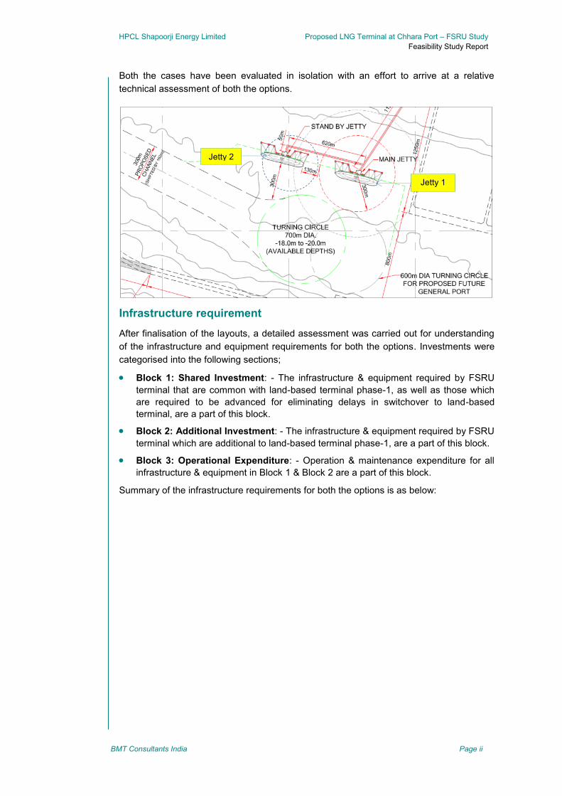
Both the cases have been evaluated in isolation with an effort to arrive at a relative
technical assessment of both the options.
Infrastructure requirement
After finalisation of the layouts, a detailed assessment was carried out for understanding
of the infrastructure and equipment requirements for both the options. Investments were
categorised into the following sections;
Block 1: Shared Investment: - The infrastructure & equipment required by FSRU
terminal that are common with land-based terminal phase-1, as well as those which
are required to be advanced for eliminating delays in switchover to land-based
terminal, are a part of this block.
Block 2: Additional Investment: - The infrastructure & equipment required by FSRU
terminal which are additional to land-based terminal phase-1, are a part of this block.
Block 3: Operational Expenditure: - Operation & maintenance expenditure for all
infrastructure & equipment in Block 1 & Block 2 are a part of this block.
Summary of the infrastructure requirements for both the options is as below:
Jetty 1
Jetty 2
HPCL Shapoorji Energy Limited Proposed LNG Terminal at Chhara Port – FSRU Study
Feasibility Study Report
BMT Consultants India Page iii
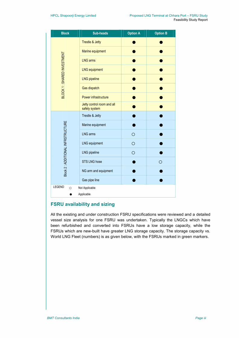
Block Sub-heads Option A Option B
BLO
CK
1 :
SH
AR
ED
INV
ES
TM
EN
T
Trestle & Jetty ● ●
Marine equipment ● ●
LNG arms ● ●
LNG equipment ● ●
LNG pipeline ● ●
Gas dispatch ● ●
Power infrastructure ● ●
Jetty control room and all safety system ● ●
Blo
ck 2
: A
DD
ITIO
NA
L IN
FR
ST
RU
CT
UR
E
Trestle & Jetty ● ●
Marine equipment ● ●
LNG arms ○ ●
LNG equipment ○ ●
LNG pipeline ○ ●
STS LNG hose ● ○
NG arm and equipment ● ●
Gas pipe line ● ●
LEGEND ○ Not Applicable
● Applicable
FSRU availability and sizing
All the existing and under construction FSRU specifications were reviewed and a detailed
vessel size analysis for one FSRU was undertaken. Typically the LNGCs which have
been refurbished and converted into FSRUs have a low storage capacity, while the
FSRUs which are new-built have greater LNG storage capacity. The storage capacity vs.
World LNG Fleet (numbers) is as given below, with the FSRUs marked in green markers.

HPCL Shapoorji Energy Limited Proposed LNG Terminal at Chhara Port – FSRU Study
Feasibility Study Report
BMT Consultants India Page iv
Range of FSRU size availability falls between 135,000 m3 to 170,000 m
3 as highlighted in
the above graphic. Given the overall trend for large storage capacity new-built FSRUs, for
the purpose of this study, design vessel size of 150,000 m3 with a re-gas capacity of 2.5-3
MTPA has been considered.
Facility for receiving LNG including FSRU is designed for handling Qmax vessels. This
comes with a constraint that the capacity of the supply vessel is much larger than the
storage vessel, which would translate into higher unloading time and berth occupancy or
part shipment may be required. Typically, the supply vessel should be lesser of equal to
the capacity of the FSRU. However, from design perspective, we do not anticipate any
significant change in the technical feasibility and the costs.
Marine assessment
Technical feasibility of the options was studied in detail from marine assessment
perspective covering the following heads:
Mooring layout as available in the DFR was studied and critically assessed for use
with the two options under the purview of this study. Various mooring configurations
were studied based on a desk top mooring assessment and it was concluded that:
For option A, two additional mooring dolphins will be required for safe
mooring of LNGC. This assessment was done using Qmax LNGC, but
requirement of additional mooring dolphins is still envisaged for smaller
supply vessels as well.
No changes in the mooring layout are envisaged for option B
An additional platform to accommodate the HP NG arm will be required
adjacent to Jetty 1. However, as an Option, mooring of a FSRU with a 10m
shift fore side to accommodate a HP loading arm on the unloading platform
was also investigated and found feasible. The downside of this alternative is
that the FSRU will have to be moored port side, and emergency sail out
scenarios can be difficult. A detailed risk assessment for such a case needs
to be carried out.
~ 135,000 m3
~ 170,000 m3
HPCL Shapoorji Energy Limited Proposed LNG Terminal at Chhara Port – FSRU Study
Feasibility Study Report
BMT Consultants India Page v
No changes in the mooring layout are envisage for option B
Docking and mooring system requirements for both the options were studied and
detailed requirements have been provided in the body of the report.
Similarly, fendering requirements for both the options were studied and detailed
requirements have been provided in the body of the report.
Navigation safety and requirements were assessed from the perspective of:
During the offloading process, the mooring arrangement should ensure that
the carrier manifold stays within the operating envelope of the loading arm
during LNG transfer.
The FSRU will be equipped with either standard unloading arms or flexible
hoses. The unloading arms will be similar to the type used in onshore
terminals, but modified to account for relative motions between LNGC and
FSRU. The FSRU will also be fitted with equipment for guiding the arms onto
the carrier’s connection flanges.
General recommendations for operational wave height limits (Hs) for safe unloading
arm operations were arrived at as follows:
Option A: Ship to Ship (STS) operations, Hs < 0.7m using hard arms.
Operating limits for use of cryogenic hoses must be studied in details, but are
expected to be in the range of Hs = 0.7 to 1.5m.
Option B: Conventional operations. Hs < 1.5m
It must be noted that the above figures are indicative only and should
be used with caution for planning purposes only. Detailing modelling
and mooring analysis should be carried out and limits w.r.t. relative
motions of the vessels must be known and cargo transfer system then
designed accordingly.
Under Keel clearance was studied and considered adequate
A desktop assessment for manoeuvring safety was carried out and considered
adequate.
From an overall perspective both the options are considered technically feasible.
For option A, the only major show stopper could be the tranquility conditions at the
berth for STS operations. Indicative limits for STS operations have been provided.
Project timeline
The project timeline has been worked out, based upon industry benchmarks. In general
the timeline is estimated to be 23 months and 27 months for the two options Option-A and
Option-B. A broad outline follows:
Marine activities fall on the critical path. Other activities are subject to the marine
construction. Therefore all marine activities considered together have an estimated
timeline of 18 months and 22 months for Option-A and Option-B respectively.
Start of the topside activities are constrained by two issues. The equipment delivery
lead-time and the availability and suitability of the location, i.e. trestle, jetty,
foundation, etc. Considering all the process activities together, we estimate timelines
of 18 months and 20 months for Option-A and Option-B respectively.
A FSRU availability timeline of 15 months has been considered, which is a broad and
conservative estimate. In practice this may vary from as low as 6 months to as high
HPCL Shapoorji Energy Limited Proposed LNG Terminal at Chhara Port – FSRU Study
Feasibility Study Report
BMT Consultants India Page vi
as 24 months, depending on the current availability and the commitment status of
different suppliers.
For Option A, FSRU procurement and delivery is the critical path activity and this is
subject to market dynamics and may not eventually cause a time constraint. If FSRU is
found not on the critical path, then long lead items such as high pressure NG arm and
cryogenic LNG arms, along with jetty construction are found to be on the critical paths.
For Option B, since two jetties have to be constructed, the marine construction activities
fall on the critical path. This leads to some process commissioning activities also to fall on
the critical path. FSRU delivery is therefore a non-critical activity.
Budget cost estimates
Cost estimates were based on secondary sources and therefore may be considered as
budgetary costs estimates with a tolerance of +/- 20%.
Cost estimation for Block 1 activities were not made, and cost for development of
additional infrastructure for both the options are as tabulated below:
Block Million USD
Option A – Additional infrastructure CAPEX (Block 2) 30.90
Option A – OPEX (Block 3) 67.00
Option B – Additional infrastructure CAPEX (Block 2) 69.80
Option B – OPEX (Block 3) 71.80
Details on preservation costs and disposal values have been provided.
Environmental considerations
Broad assessment of environmental consideration was carried out and it was concluded
the activity is a permissible activity requiring environmental clearance from the Ministry of
Environment and Forests (MoEF), Government of India. The typical process leading to
environmental clearance has been provided in the report and is summarised as below:
A fresh TOR for the LNG terminal with FSRU to be sought from MoEF for EC of the
LNG Terminal..
Following aspects need to be included in the EIA report of the LNG Terminal:
Description of the FSRU focusing on the process flow rates, seawater
requirements for vaporizing LNG (125,000 KLD) and safety measures
included in the design. The layout of the natural gas pipelines needs to be
chosen such that future expansion of the port does not interfere with
operations of the LNG terminal.
Prediction chapter needs to include
Thermal dispersion modeling identifying the intake and outfall
location for discharge of coldwater
Impacts on marine ecology due to the disposal of cold water
Entrainment of marine life at the intake system
Release of free chlorine at the outfall
o Risk Analysis

HPCL Shapoorji Energy Limited Proposed LNG Terminal at Chhara Port – FSRU Study
Feasibility Study Report
BMT Consultants India Page vii
Quantitative Risk Analysis - Consequence Analysis, frequency,
computation of risk, separation zones for FSRU
Navigational safety
o EMP/DMP
Include onsite and offsite plans, training, awareness and drills
The EIA report for the LNG terminal including FSRU will need to be submitted for
CRZ approval from State Government.
An application for environmental clearance will need to be made together with the EIA
study report, HTL/LTL demarcation, minutes of the Public hearing, CRZ approval and
the Detailed Project Report.
Way forward
After consideration of all the above factors, Option A is the preferred option owing to
being the cost effective in relation to option B. We recommend Option A be
considered as the preferred option.
We suggest the following way forward:
Detailed and location specific tranquillity studies
Application to MoEF for issue of TOR for the LNG terminal with an FSRU option.
An application for environmental clearance together with the EIA study report,
HTL/LTL demarcation, minutes of the Public hearing, CRZ approval and the Detailed
Project Report.
A separate risk assessment
Undertake an operational-based and design-based mooring evaluation.
HPCL Shapoorji Energy Limited Proposed LNG Terminal at Chhara Port – FSRU Study
Feasibility Study Report
BMT Consultants India Page ix
Contents
1 Introduction ......................................................................................... 1
Background ...................................................................................................... 1 1.1
Scope of work .................................................................................................. 1 1.2
Meetings and visits .......................................................................................... 2 1.3
1.3.1 Project kick-off meeting and site visit. ................................................. 2
Data consulted ................................................................................................. 2 1.4
1.4.1 List of data received ............................................................................ 2
1.4.2 Basis of design received from SP/HPCL ............................................ 3
1.4.3 Data limitations ................................................................................... 4
1.4.4 Design constraints .............................................................................. 4
Format of the report ......................................................................................... 4 1.5
2 Site information ................................................................................... 6
Location ............................................................................................................ 6 2.1
Chhara port ...................................................................................................... 6 2.2
2.2.1 Marine master plan ............................................................................. 6
2.2.2 Land use ............................................................................................. 7
2.2.3 LNG handling facility ........................................................................... 7
Met-Ocean conditions ...................................................................................... 8 2.3
2.3.1 Tides ................................................................................................... 9
2.3.2 Currents .............................................................................................. 9
2.3.3 Wind and waves .................................................................................. 9
3 Discussion on layouts and infrastructure requirement ................. 12
Project description ......................................................................................... 12 3.1
Layout options ................................................................................................ 12 3.2
Discussion on options .................................................................................... 13 3.3
3.3.1 Option A ............................................................................................ 13
3.3.2 Option B ............................................................................................ 15
3.3.3 Pipeline rack adequacy ..................................................................... 16
Infrastructure requirements ............................................................................ 17 3.4
3.4.1 Shared investment –Block 1 ............................................................. 17
3.4.2 Additional investment block – Block 2 .............................................. 19
3.4.3 Operational expenditure (OPEX) ...................................................... 22
4 FSRU availability and sizing ............................................................ 24
FSRU availability ............................................................................................ 24 4.1
FSRU fleet ...................................................................................................... 24 4.2
4.2.1 Golar LNG ......................................................................................... 25
4.2.2 Hoegh LNG ....................................................................................... 26
4.2.3 Excelerate Energy ............................................................................. 26
4.2.4 BW Gas ............................................................................................. 27
4.2.5 OLT Offshore .................................................................................... 28
4.2.6 Others LNG shippers ........................................................................ 28
FSRU sizing ................................................................................................... 28 4.3

HPCL Shapoorji Energy Limited Proposed LNG Terminal at Chhara Port – FSRU Study
Feasibility Study Report
BMT Consultants India Page x
Summary ........................................................................................................ 29 4.4
5 Marine assessment ........................................................................... 31
Mooring layout assessment ........................................................................... 31 5.1
5.1.1 Dolphin spacing ................................................................................ 32
5.1.2 Mooring dolphin set-back .................................................................. 32
5.1.3 Mooring line angle criteria ................................................................. 32
5.1.4 Mooring layout .................................................................................. 33
5.1.5 Gas discharge ................................................................................... 35
Docking and mooring systems ....................................................................... 38 5.2
5.2.1 Fendering requirement ...................................................................... 41
Navigational requirements ............................................................................. 42 5.3
5.3.1 Wave tranquility ................................................................................ 42
5.3.2 Wind .................................................................................................. 45
5.3.3 Under Keel clearance ....................................................................... 47
5.3.4 Manoeuvring safety ........................................................................... 49
Summary ........................................................................................................ 50 5.4
6 Early commissioning timelines and cost assessment .................. 51
Project time line.............................................................................................. 51 6.1
6.1.1 Marine facilities ................................................................................. 51
6.1.2 Topside facilities ............................................................................... 51
6.1.3 FSRU timeline ................................................................................... 52
6.1.4 Statutory clearances ......................................................................... 52
6.1.5 Breakwater ........................................................................................ 52
6.1.6 DPR / FEED ...................................................................................... 52
6.1.7 Critical path ....................................................................................... 53
Budget cost estimates .................................................................................... 56 6.2
6.2.1 CAPEX & OPEX ............................................................................... 56
6.2.2 FSRU lease estimates basis ............................................................. 59
6.2.3 Preservation & disposal value........................................................... 59
7 Process description and environmental considerations .............. 60
Brief description of FSRU .............................................................................. 60 7.1
7.1.1 LNG reception from LNGC ................................................................ 60
7.1.2 LNG Re-gasification to NG and dispatch .......................................... 61
7.1.3 Boil-off gas (BOG) management....................................................... 61
7.1.4 Infrastructure requirements ............................................................... 61
Environmental considerations ........................................................................ 62 7.2
8 Conclusion and way forward ........................................................... 65
Conclusion ..................................................................................................... 65 8.1
Way forward ................................................................................................... 65 8.2
9 Drawings ............................................................................................ 67

HPCL Shapoorji Energy Limited Proposed LNG Terminal at Chhara Port – FSRU Study
Feasibility Study Report
BMT Consultants India Page xi
Tables
Table 2-1: Predicted tide levels at Chhara - Indian Admirality Chart 206 & 207 ........ 9
Table 2-2: Summary of offshore and near shore wave characteristics extracted from EIA report................................................................................................. 11
Table 3-1: Block 1 infrstructure requirements ........................................................... 19
Table 3-2: Block 2 infrstructure requirements ........................................................... 22
Table 4-1: Summary of FSRU fleet ........................................................................... 29
Table 4-2: FSRU generic specifications ................................................................... 30
Table 5-1: Calculation of gross depth requirements ................................................. 48
Table 6-1: Budget CAPEX estimates Option-A; Block-2 .......................................... 57
Table 6-2: Budget OPEX estimates Option-A; Block-3 ............................................ 57
Table 6-3: Budget CAPEX estimates Option-B; Block-2 .......................................... 58
Table 6-4: Budget OPEX estimates Option-B; Block-3 ............................................ 58
Figures
Figure 2-1: Google earth image showing location of the port ...................................... 6
Figure 2-2: Marine master plan of Chhara Port ........................................................... 7
Figure 2-3: LNG berthing facility .................................................................................. 8
Figure 2-4: LNG back up area ..................................................................................... 8
Figure 3-1: Location of options in proposed Chhara Port .......................................... 13
Figure 3-2: Pipe line routing superimposed with option A ......................................... 15
Figure 3-3: Pipe line routing superimposed with option B ......................................... 16
Figure 4-1: Storage Capacity (m3) vs. World LNG Fleet ............................................ 28
Figure 5-1: Option A – Mooring arrangement on mooring layout proposed in DFR .. 33
Figure 5-2: Option A – Alternative mooring layout ..................................................... 34
Figure 5-3: Option B – Tandem operations on adjacent jetties ................................. 35
Figure 5-4: FSRU berthing SST ................................................................................. 36
Figure 5-5: FSRU berthing PST ................................................................................. 37
Figure 5-6: FSRU berthing PST – moored with a 10m shift fore of the ship ............. 38
Figure 5-7: Typical STS configuration........................................................................ 43
Figure 5-8: Wind scatter table .................................................................................... 46
Figure 5-9: Conceptual design of underkeel clearance (UKC) requirements ............ 49
Figure 6-1: Project timeline – Option A ...................................................................... 54
Figure 6-2: Project timeline – Option B ...................................................................... 55
Figure 7-1: FSRU terminal block diagram.................................................................. 60
Appendix
Appendix A: Qualitative Risk Assessment
HPCL Shapoorji Energy Limited Proposed LNG Terminal at Chhara Port – FSRU Study
Feasibility Study Report
BMT Consultants India Page xii
SYMBOLS AND ABBREVIATIONS
Symbols and abbreviations used are generally in accordance with the following list.
1 Proper names and organisations - India
BIS .................. Bureau of Indian Standards
BMT CI ............ BMT Consultants (India) Private Limited
GoI .................. Government of India
IMD ................. Indian Meteorological Department
MoEF .............. Ministry of Environment and Forests
MoS ................ Ministry of Shipping
NIOT ............... National Institute of Ocean Technology
SoI .................. Survey of India
HPCL………….Hindustan Petroleum Corporation Ltd
SPPPL ………..Shapoorji Pallonji Ports Private Limited
HSEL………….HPCL Shapoorji Energy Limited
CES……………Consulting Engineering Services Pvt. Ltd
2 Proper names and organisations – Other
BA ................... British Admiralty
BS ................... British Standard
IMO ................. International Maritime Organization
ISPS ................ International Ship and Port facility Security code
NCEP .............. National Centre for Environmental Prediction
NCAR .............. National Centre for Atmospheric Research
OCIMF ............ Oil Companies International Marine Forum
PIANC ............. Permanent International Association of Navigation Congresses
OISD ............... Oil Industry Safety Directorate
SIGGTO .......... Society of International Gas Tanker and Terminal Operators
3 Other abbreviations
Approx. ........... approximately
cif .................... cost, insurance, freight
dia ................... diameter
fob ................... free on board
max ................. maximum
min .................. minimum

HPCL Shapoorji Energy Limited Proposed LNG Terminal at Chhara Port – FSRU Study
Feasibility Study Report
BMT Consultants India Page xiii
No ................... number (order) as in No 6
nr ..................... number (units) as in 6 nr
DAS ................ Docking Aid System
DFR ................ Detailed Feasibility Report
DMP ................ Disaster Management Plan
EIA .................. Environmental Impact Assessment
EMP ................ Environment Management Plan
FSRU .............. Floating Storage and Re-gasification Unit
LNGC .............. LNG carrier
HAT ................. Highest Astronomical Tide
MHWS ............ Mean High Water Spring tides
MSL ................ Mean Sea Level
MLWS ............. Mean Low Water Spring tides
LAT ................. Lowest Astronomical Tide
HTL……………High tide line
CD ................... Chart Datum
LOA ................. Length overall (of a ship)
LNG ................ Liquefied Natural Gas
M ..................... “mega” or one million (106)
MoU ................ Memorandum of Understanding
NG .................. Natural Gas
ToR ................. Terms of Reference
UKC ................ Under Keel Clearance
STS……………Ship to ship
QRMH…………Quick release mooring hooks
4 Units of measurement
Length, area and volume
mm .................. millimeter(s)
m ..................... meter(s)
km ................... kilometer(s)
n. mile ............. nautical mile(s)
mm2 ................. square millimeter(s)
m2 .................... square meter(s)
km2 .................. square kilometer(s)

HPCL Shapoorji Energy Limited Proposed LNG Terminal at Chhara Port – FSRU Study
Feasibility Study Report
BMT Consultants India Page xiv
ha .................... hectare(s)
m3 .................... cubic meter(s)
kl ..................... kilo liter(s)
MSCMD .......... Million standard cubic metres(of natural gas) per day
MTPA .............. Million tonnes per day
mbtu…………. Million British thermal units
Time and time derived units
s ...................... second(s)
min .................. minute(s)
h ...................... hour(s)
d ...................... day(s)
wk ................... week(s)
mth .................. month(s)
yr ..................... year(s)
mm/s ............... millimeters per second
km/h ................ kilometers per hour
m/s .................. metres per second
knot ................. nautical mile per hour
Mass, force and derived units
kg .................... kilogram(s)
g ...................... gram = kg x 10-3
t ....................... tonne = kg x 103
Mt .................... million tonnes = t x 106
displacement ... the total mass of the vessel and its contents. (This is equal to the volume
of water displaced by the vessel multiplied by the density of the water.)
DWT ................ dead weight tonne, the total mass of cargo, stores, fuels, crew and
reserves with which a vessel is laden when submerged to the summer
loading line. (Although this represents the load carrying capacity of the
vessel it is not an exact measure of the cargo load).
Other units
°C .................... degrees Celsius (temperature)
tpd ................... tonnes per day
tph ................... tonnes per hour
MW ................. Mega Watts
HPCL Shapoorji Energy Limited Proposed LNG Terminal at Chhara Port – FSRU Study
Feasibility Study Report
BMT Consultants India Page 1
1 Introduction
Background 1.1
M/s Hindustan Petroleum Corporation Ltd (HPCL) in a Joint Venture with SP Ports
Private Limited (SPPPL) is in the process of setting up a LNG re-gasification terminal at
Chhara in District Junagadh, Gujarat.
HSEL has carried out Detailed Feasibility Studies for the on-shore based storage and re-
gasification terminal Through Tractable Engineering and is now desires to undertake
technical feasibility studies for installation of FSRU based terminal as a bridging facility to
bridge the gap between readiness of the port marine facilities and on shore topside
facilities.
BMT Consultants India Limited (BMTCI) has been engaged by HSEL develop a technical
feasibility report on marine and process aspects for early commissioning LNG terminal
with FSRU. FSRU can be deployed to take advantage of the time lag between readiness
of construction of marine facilities and on share storage and regasification facilities to
feed the market early.
Scope of work 1.2
The purpose of this study is to arrive at a sufficiently accurate definition of planned marine
facilities for setting up of a FSRU based terminal at the selected location for future LNG
jetties at the proposed Chhara terminal.
The main objectives of the study are:
To review available information on the proposed Chhara terminal provided by the
client.
Carry out conceptual study for selection of possible options for FSRU
Assess the various aspects of the proposed jetty as designed in the DFR Study for its
suitability for FSRU operation. Also, recommend changes in the jetty layout for
accommodating a FSRU taking into account the following:
Berthing of FSRU and unloading arrangement for the LNG supply vessel.
Evacuation of RLNG from FSRU to send out facilities of the proposed
LNG terminal.
Environment & Safety considerations.
Undertake a high level conceptual assessment and sizing of FSRU keeping in view
the LNG volume as per client requirement defined above.
Assess the Technical feasibility of the FSRU keeping in view the following aspects.
Total investment for 2/3/5 years (Capex, Opex, Contingencies, etc.) for
leased unit.
Economics of vessels sizing and lease model for FSRU.
Identifying all regulatory and Environmental clearances required.

HPCL Shapoorji Energy Limited Proposed LNG Terminal at Chhara Port – FSRU Study
Feasibility Study Report
BMT Consultants India Page 2
Identifying various milestones & project timelines to start FSRU installation
and operations keeping in view the project schedule for implementation of
overall LNG re‐gasification terminal decided upon in the DFR.
Assess constructability aspects keeping in view the operating FSRU
while LNG terminal construction is in progress.
Undertake qualitative risk assessment for this scenario.
Prepare block cost estimates CAPEX/OPEX for the project investment.
Meetings and visits 1.3
1.3.1 Project kick-off meeting and site visit.
A kick off meeting to discuss the way forward and project kick off meeting was held at
Mumbai on 1st
October. Officials from SP, HPCL and BMT attended the meeting. Various
options were discussed in the meeting and following two options were finalised to be
studied:
FSRU Double Banking with LNGC
FSRU Tandem Berthing with LNGC (Using Two Jetties)
Data consulted 1.4
1.4.1 List of data received
The following data was received from HSEL.
Environmental Impact Assessment & Environmental Management Plan report for
Phase 1 of Port at Chhara by CES
Detailed Feasibility Report for Chhara LNG project by Tractabel Engineering. The
contents of the DFR received were as follows:
Process Design Basis
Optimized Scheme & Estimated Utility Consumptions
BOG Handling
Send-out system-Relief System
Equipment Sparing Philosophy
Fire Water System
Marine specifications
Civil design basis
Effluent Disposal Philosophy
Pollution control and Mitigation
Piping Design Basis
Piping Material Specification
Site screening
Valves specification
Low Temperature Thermal Insulation

HPCL Shapoorji Energy Limited Proposed LNG Terminal at Chhara Port – FSRU Study
Feasibility Study Report
BMT Consultants India Page 3
Painting and Protective coatings
Welding, Heat Treatment and Inspection
Specifications for Cryogenic Marine Transfer Arms
Mooring line tensioning & Ship approach monitoring
Ship Access Gangway
Project Design Basis
Low Temperature Flare Stack Specification
Applicable Codes & Standards
Project Execution Plan
Project Schedule
List of Statutory and Regulatory Approvals
Operation and Maintenance Organization
Utilities and Auxiliary systems
Marine Design
Cryogenic Insulation Classes
Electrical Design Basis
Hazardous area classification and choice of electrical material
Power source optimization
Instrumentation Specification for package unit
Fire, Spill & Gas Detection system
Communication and Security
Instrument & Control system
Plant Control and Monitoring System
Continuous Emissions Monitoring System
Emergency Shut-down (ESD) Philosophy
Fire, Hazard & Safety Systems
RLNG Evacuation Plan
LNG Truck Tanker Loading facilities
Custody transfer description
Risk Analysis, & DMP
Project drawings
1.4.2 Basis of design received from SP/HPCL
Based on the advice received from SP/HPCL, the following design basis has been
adopted:
Regasification capacity to be considered - minimum of 2.5 MTPA.
Maximum size of carrier to be considered – Qmax
HPCL Shapoorji Energy Limited Proposed LNG Terminal at Chhara Port – FSRU Study
Feasibility Study Report
BMT Consultants India Page 4
1.4.3 Data limitations
The study was based upon available site information and data. Where these were
unavailable, assumptions have been made. The data and related assumptions will need
to be carefully elaborated and re-examined during subsequent stages of the project
development.
The data limitations of this study apply in particular to:
Numerical model studies for the terminal plan to understand the wave and current
regime at the proposed jetty location. Relevant reports for the overall port
development were critically reviewed for the study and it is recommended detailed
studies are undertaken location specific to LNG terminal in the advanced stages of
execution of this project. Current review of the data is considered adequate for
determination of the feasibility at this stage.
Design, alignment and extent of breakwater protection proposed for the LNG jetty
location. Detailed mathematical model studies will be needed to be undertaken in
the detail design stage. Current review of the data is considered adequate for
determination of the feasibility at this stage.
Risk assessment of FSRU. Risk assessment for LNG terminal including marine
facilities as carried out in Detailed Feasibility Study has been reviewed. A fresh
study would need to be undertaken to update the report for FSRU and STS
operations.
The above list is not exhaustive.
1.4.4 Design constraints
Given the overall trend for large storage capacity new-built FSRUs, range of FSRU
availability falls between 135,000 m3 to 170,000 m
3. For the purpose of this study, design
vessel size of 150,000 m3 with a re-gas capacity of 2.5-3 MTPA has been considered.
Format of the report 1.5
The following chapters constitute the remainder of this report:
Chapter 2 provides the site information consolidated after review of the data available
with BMT for the study. The section mainly elaborates on the environmental information
specific to the site relevant for the feasibility of locating a FSRU based LNG terminal at
the proposed LNG jetty in Chhara port.
Chapter 3 elaborates on infrastructure requirements for the layout options, investment
required thereof and discussion on various layouts
Chapter 4 provides a detailed vessel size analysis for FSRU sizing.
Chapter 5 elaborates on the technical feasibility of the options from the marine safety,
mooring layout and manoeuvrability perspectives.
Chapter 6 provides a detailed time lines for the options studied and cost estimates.

HPCL Shapoorji Energy Limited Proposed LNG Terminal at Chhara Port – FSRU Study
Feasibility Study Report
BMT Consultants India Page 5
Chapter 7 provides a brief explanation on the process description, environmental
considerations and recommendations for obtaining environmental clearance
Chapter 8 outlines recommendations and a way forward
Chapter 9 Drawings
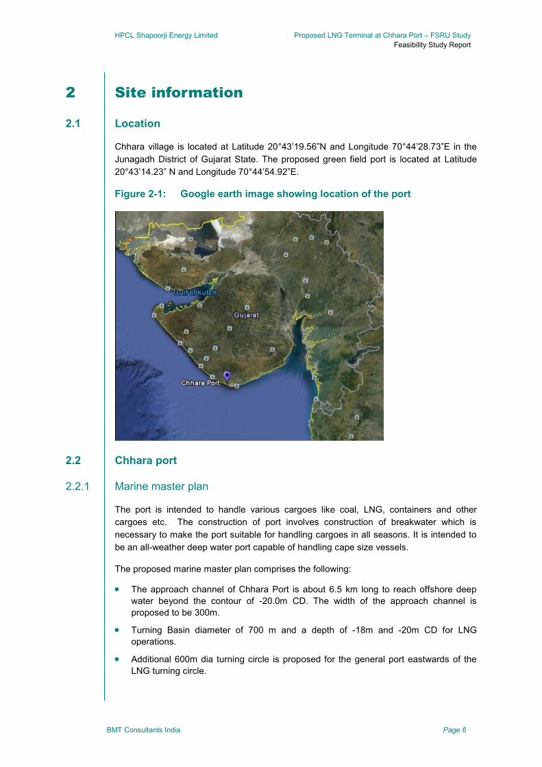
HPCL Shapoorji Energy Limited Proposed LNG Terminal at Chhara Port – FSRU Study
Feasibility Study Report
BMT Consultants India Page 6
2 Site information
Location 2.1
Chhara village is located at Latitude 20°43’19.56”N and Longitude 70°44’28.73”E in the
Junagadh District of Gujarat State. The proposed green field port is located at Latitude
20°43’14.23” N and Longitude 70°44’54.92”E.
Figure 2-1: Google earth image showing location of the port
Chhara port 2.2
2.2.1 Marine master plan
The port is intended to handle various cargoes like coal, LNG, containers and other
cargoes etc. The construction of port involves construction of breakwater which is
necessary to make the port suitable for handling cargoes in all seasons. It is intended to
be an all-weather deep water port capable of handling cape size vessels.
The proposed marine master plan comprises the following:
The approach channel of Chhara Port is about 6.5 km long to reach offshore deep
water beyond the contour of -20.0m CD. The width of the approach channel is
proposed to be 300m.
Turning Basin diameter of 700 m and a depth of -18m and -20m CD for LNG
operations.
Additional 600m dia turning circle is proposed for the general port eastwards of the
LNG turning circle.

HPCL Shapoorji Energy Limited Proposed LNG Terminal at Chhara Port – FSRU Study
Feasibility Study Report
BMT Consultants India Page 7
The basin is proposed to be protected by a rubble mound breakwater. The
breakwater is at a distance of about 2.5 km from the shore and aligned parallel to the
shore on the shoal bank.
Two shore connected jetties are proposed for LNG operations, one proposed to act
as a stand-by jetty. These jetties are connected to shore via 1120m long approach
trestle common for two jetties.
A1200m long quay is proposed for multipurpose cargo operations east of LNG jetties,
connected to shore with three approaches.
Provision has also been made for an offshore 1500m long quay for bulk operations
aligned to the breakwater.
Figure 2-2: Marine master plan of Chhara Port
2.2.2 Land use
The backup area has been planned with well demarcated areas of use for handling
different types of cargo like, coal, containers, liquid, LNG etc. Study of the land use for
other cargo is outside the purview of this study and the subsequent sections will be
limited to discussions on LNG handling facility proposed at the port.
2.2.3 LNG handling facility
The LNG import terminal, storage and re-gasification facilitates are being planned as an
overall part of the port development.
The LNG import terminal is planned to be developed with separate standalone jetty
facilities west of the proposed coal berths. The storage/re-gasification plant is planned to
be based on the landward side beyond high tide line (HTL).

HPCL Shapoorji Energy Limited Proposed LNG Terminal at Chhara Port – FSRU Study
Feasibility Study Report
BMT Consultants India Page 8
The LNG terminal is planned to be developed in two phases, 5 MTPA during Phase-I with
provision for expansion up to 10 MMTPA in Phase 2.
Figure 2-3: LNG berthing facility
Figure 2-4: LNG back up area
Met-Ocean conditions 2.3
The western coast of Gujarat is characterised by strong SW monsoons and relatively low
intensity NE monsoons.
The typical climatic seasons are

HPCL Shapoorji Energy Limited Proposed LNG Terminal at Chhara Port – FSRU Study
Feasibility Study Report
BMT Consultants India Page 9
Pre-monsoon – March to May
Southwest Monsoon – June to September
Post monsoon – October to Mid-November
Northeast Monsoon – Mid November to February
2.3.1 Tides
The tidal range at Chhara is predicted to be about 2.9m according to the Indian Admiralty
Charts 206 & 207 with respect to Chart Datum are provided in Table 2-1 below
Table 2-1: Predicted tide levels at Chhara - Indian Admirality Chart 206 &
207
Tide Level (m)
Highest Astronomical Tide (HAT) +2.80 m CD
Mean High Water Spring (MHWS) +2.20 m CD
Mean Low Water Spring (MLWS) +1.86 m CD
Mean Sea Level +1.48 m CD
Mean High Water neap (MHWN) +1.32 m CD
Mean Low Water Neap (MLWN) +0.64 m CD
Lowest Astronomical Tide (LAT) -1.0 m CD
2.3.2 Currents
Based upon the information provided in various reports made available by SP/HPCL, the
general flooding current is predominant along the coast during the SW monsoon and is
generally in the direction south east with a maximum speed at surface of about 0.83 m/s.
Ebb currents are dominant on west directions with a maximum speed at surface of about
0.8 m/s.
This data has been collected at two off shore locations of current measurements and are
therefore not site specific measurements. BMT has not carried out any independent data
procurement or physical verification of the above data or on the existing current regime at
the location and has used existing data for their assessment.
2.3.3 Wind and waves
Based upon the information provided in various reports such as EIA study, DFR, etc. the
wind during the monsoon months of June, July and August is predominantly south
westerly with speeds ranging from 15 to 30 knots. The wind during the pre-monsoon is
generally westerly and towards the end has also recorded wind events ranging from 22 to
28 knots. Wind during the remaining months is predominantly north westerly with speeds
ranging from 10 to 20 knots.
The wave climate is dominated by the monsoon conditions, with the most extreme waves
occurring during the south west monsoon between mid-June and mid-October.

HPCL Shapoorji Energy Limited Proposed LNG Terminal at Chhara Port – FSRU Study
Feasibility Study Report
BMT Consultants India Page 10
HR Wallingford’s study for Chhara site shows that majority of offshore waves come from
south-west and westerly direction sectors (195-285°N). The maximum significant wave
height (up to 5.7m) is predicted in the sector 225-255°N. About 80 % waves are within the
range 5 to 9s mean period. There are a number of longer period wave conditions with
mean periods in the range 10 to 14s, though the associated wave heights are less than
Hs = 3m. The predicted extreme offshore waves approach the site from the sector
centered 240°N. The predicted 1 in 1 year significant wave heights from this directions
Hs = 5.0m with peak period 10.25. This increases to Hs = 6.2 m for 1 in 200 year
condition, with Tp = 11.4s.
Offshore and near shore wave climate results on the -10mCD, -15 m CD and -20mCD
depth contours extracted from the SWAN model are shown in Table 2-2. For the
frequently occurring conditions the largest near shore waves are generated by waves
from the 240°N offshore direction. 1 in 1 year waves from this direction resulted in near
shore waves of Hs = 3.6m on the -20mCD contour, shoaling to 3.7m on -10m CD contour.
For the longer return periods the more southerly direction 180°N sectors become
increasingly important. At the 1 in 200 year level, the predicted wave heights near the
breakwater result in Hs = 4.5-5.0m and slightly reduce to 4.0-4.5m over the shoal bank.
The predicted extreme waves approach the site from the sector centered on 240°N. The
predicted 1 in 1 year significant wave height from this direction is Hs = 5.0 m, with a peak
period Tp = 10.2s, which increases to Hs=6.2 for 200 year condition, with Tp = 11.4s.
BMT has reviewed and used data made available from HSEL and other third party data
on the existing current regime at the location for assessment.
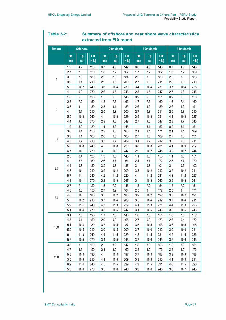
HPCL Shapoorji Energy Limited Proposed LNG Terminal at Chhara Port – FSRU Study
Feasibility Study Report
BMT Consultants India Page 11
Table 2-2: Summary of offshore and near shore wave characteristics
extracted from EIA report
Return Offshore 20m depth 15m depth 10m depth
Hs
(m)
Tp
(s)
Dir
(o N)
Hs
(m)
Tp
(s)
Dir
(o N)
Hs
(m)
Tp
(s)
Dir
(o N)
Hs
(m)
Tp
(s)
Dir
(o N)
1
1.2 4.7 120 0.7 4.9 142 0.6 4.9 146 0.7 4.9 143
2.7 7 150 1.8 7.2 162 1.7 7.2 162 1.6 7.2 169
3 7.9 180 2.2 7.9 184 2.2 8 180 2.2 8 188
3.9 9.1 210 2.9 9.3 209 2.7 9.3 211 2.8 9.3 210
5 10.2 240 3.6 10.4 230 3.4 10.4 231 3.7 10.4 228
4 9.2 270 2.6 9.5 248 2.5 9.5 247 2.7 9.6 245
5
1.8 5.8 120 1 6 145 0.9 6 151 0.9 6 150
2.8 7.2 150 1.8 7.3 163 1.7 7.3 169 1.6 7.4 169
3.8 9 180 2.8 9.1 185 2.6 9.2 189 2.6 9.2 191
4 9.1 210 2.9 9.3 209 2.7 9.3 211 2.9 9.3 210
5.5 10.8 240 4 10.8 229 3.8 10.8 231 4.1 10.9 227
4.4 9.6 270 2.8 9.6 248 2.7 9.6 247 2.9 9.7 245
10
1.9 5.9 120 1.1 6.2 146 1 6.1 152 0.9 6.1 151
3.6 8.1 150 2.3 8.3 163 2.1 8.4 171 2.1 8.4 169
3.9 9.1 180 2.8 9.3 185 2.7 9.3 189 2.7 9.3 191
4.5 9.7 210 3.3 9.7 209 3.1 9.7 212 3.3 9.8 211
5.5 10.8 240 4 10.8 229 3.8 10.8 231 4.1 10.9 227
4.7 10 270 3 10.1 247 2.9 10.2 246 3.2 10.2 244
25
2.3 6.4 120 1.3 6.6 145 1.1 6.6 153 1.1 6.6 151
4 8.5 150 2.6 8.7 164 2.4 8.7 172 2.3 8.7 170
4.4 9.6 180 3.2 9.6 186 3 9.6 191 3 9.7 192
4.8 10 210 3.5 10.2 209 3.3 10.2 212 3.5 10.2 211
5.7 11 240 4.2 11.2 229 4 11.2 231 4.3 11.2 227
4.9 10.1 270 3.2 10.3 247 3 10.3 246 3.3 10.3 244
50
2.7 7 120 1.5 7.2 146 1.3 7.2 154 1.3 7.2 151
4.3 8.8 150 2.7 8.9 164 2.5 9 172 2.5 9 171
4.8 10 180 3.5 10.2 186 3.2 10.2 192 3.3 10.2 194
5 10.2 210 3.7 10.4 209 3.5 10.4 212 3.7 10.4 211
5.9 11.1 240 4.3 11.3 229 4.1 11.3 231 4.4 11.3 226
5.1 10.4 270 3.3 10.5 247 3.1 10.5 246 3.5 10.5 243
100
3.1 7.5 120 1.7 7.8 146 1.6 7.8 154 1.6 7.8 152
4.5 9.1 150 2.9 9.3 165 2.7 9.3 173 2.6 9.4 172
5.1 10.4 180 3.7 10.5 187 3.5 10.5 193 3.6 10.5 195
5.2 10.5 210 3.9 10.5 209 3.7 10.6 212 3.9 10.6 211
6 11.3 240 4.4 11.5 229 4.2 11.5 231 4.5 11.5 226
5.2 10.5 270 3.4 10.5 246 3.2 10.6 245 3.5 10.6 243
200
3.5 8 120 2 8.2 147 1.8 8.3 156 1.8 8.3 151
4.7 9.3 150 3.1 9.5 165 2.8 9.5 173 2.8 9.5 173
5.5 10.8 180 4 10.8 187 3.7 10.8 193 3.8 10.9 196
5.5 10.8 210 4.1 10.8 209 3.9 10.8 213 4.1 10.9 211
6.2 11.4 240 4.5 11.5 229 4.3 11.5 231 4.6 11.5 226
5.3 10.6 270 3.5 10.6 246 3.3 10.6 245 3.6 10.7 243
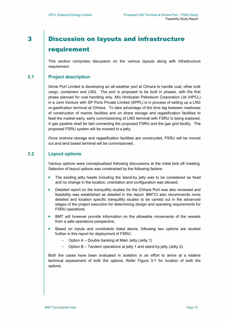
HPCL Shapoorji Energy Limited Proposed LNG Terminal at Chhara Port – FSRU Study
Feasibility Study Report
BMT Consultants India Page 12
3 Discussion on layouts and infrastructure
requirement
This section comprises discussion on the various layouts along with infrastructure
requirement.
Project description 3.1
Simar Port Limited is developing an all-weather port at Chhara to handle coal, other bulk
cargo, containers and LNG. The port is proposed to be built in phases, with the first
phase planned for coal handling only. M/s Hindustan Petroleum Corporation Ltd (HPCL)
in a Joint Venture with SP Ports Private Limited (SPPL) is in process of setting up a LNG
re-gasification terminal at Chhara. To take advantage of the time lag between readiness
of construction of marine facilities and on share storage and regasification facilities to
feed the market early, early commissioning of LNG terminal with FSRU is being explored.
A gas pipeline shall be laid connecting the proposed FSRU and the gas grid facility. The
proposed FSRU system will be moored to a jetty.
Once onshore storage and regasification facilities are constructed, FSRU will be moved
out and land based terminal will be commissioned..
Layout options 3.2
Various options were conceptualized following discussions at the initial kick-off meeting.
Selection of layout options was constrained by the following factors:
The existing jetty heads including the stand-by jetty was to be considered as fixed
and no change in the location, orientation and configuration was allowed.
Detailed report on the tranquillity studies for the Chhara Port was also reviewed and
feasibility was established as detailed in the report. BMTCI also recommends more
detailed and location specific tranquillity studies to be carried out in the advanced
stages of the project execution for determining design and operating requirements for
FSRU operations.
BMT will however provide information on the allowable movements of the vessels
from a safe operations perspective.
Based on inputs and constraints listed above, following two options are studied
further in this report for deployment of FSRU:
Option A – Double banking at Main Jetty (Jetty 1)
Option B – Tandem operations at jetty 1 and stand-by jetty (Jetty 2).
Both the cases have been evaluated in isolation in an effort to arrive at a relative
technical assessment of both the options. Refer Figure 3-1 for location of both the
options.
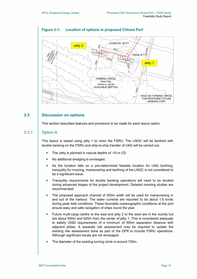
HPCL Shapoorji Energy Limited Proposed LNG Terminal at Chhara Port – FSRU Study
Feasibility Study Report
BMT Consultants India Page 13
Figure 3-1: Location of options in proposed Chhara Port
Discussion on options 3.3
This section describes features and provisions to be made for each layout option.
3.3.1 Option A
This layout is based using jetty 1 to moor the FSRU. The LNGC will be berthed with
double banking on the FSRU and ship-to-ship transfer of LNG will be carried out.
The Jetty is planned in natural depths of -15 m CD
No additional dredging is envisaged.
As the location falls on a pre-determined feasible location for LNG berthing,
tranquility for mooring, maneuvering and berthing of the LNGC is not considered to
be a significant issue.
Tranquility requirements for double banking operations will need to be studied
during advanced stages of the project development. Detailed mooring studies are
recommended.
The proposed approach channel of 300m width will be used for maneuvering in
and out of the harbour. The water currents are reported to be about 1.6 knots
during peak tidal conditions. These favorable oceanographic conditions at the port
ensure easy and safe navigation of ships round the year.
Future multi-cargo berths to the east and jetty 2 to the west are in the vicinity but
are about 500m and 620m from the center of jetty 1. This is considered adequate
to satisfy OISD requirements of a minimum of 500m separation distance with
adjacent jetties. A separate risk assessment may be required to update the
existing risk assessment done as part of the DFR to include FSRU operations.
Although significant issues are not envisaged.
The diameter of the existing turning circle is around 700m.
Jetty 1
Jetty 2

HPCL Shapoorji Energy Limited Proposed LNG Terminal at Chhara Port – FSRU Study
Feasibility Study Report
BMT Consultants India Page 14
The following infrastructure needs to be constructed in case of Option A, which as
described in the preceding section may fall either within the Block 1 CAPEX or additional
CAPEX.
Jetty 1 and approach trestle connecting to the shore needs to be constructed.
All marine equipment for conventional LNGC berthing may not be appropriate for STS
operations. Therefore mooring and fendering equipment designed for STS operations
need to be installed. This would specifically include fendering arrangements between
two vessels (typically pneumatic or foam filled fenders), mooring equipment for ship
to ship and ship to shore mooring, etc.
All LNG and process equipment including the cryogenic pipeline will need to be
installed upfront, even though this will not be used in during FSRU operations. During
regular operations on the FSRU, due to restriction affected due to the exclusion zone
(to be determined during the QRA), no hot works will be allowed within the said zone,
therefore resulting in no construction works possible on the jetty and some part of the
trestle during FSRU operations. Therefore, in order to eliminate the construction
downtime during FSRU to land-based terminal switchover (e.g. Cryogenic pipeline,
LNG unloading arms, safety equipment, etc on the jetty and trestle).
The gas evacuation line from jetty 1 to the dispatch station, metering & dispatch
station, connecting the LNG terminal with the NG off-take transmission line is also
required for FSRU operations.
The gas pipe line may be installed on pipe racks on the approach trestle, These
pipeline to be blinded off once Onshore terminal is commissioned. NG and LNG lines
will not be operational simultaneously. Therefore no major design changes are
envisaged for the approach trestle. However, geometric design of the approach
trestle must conform to this requirement.
The gas pipe-line on shore is proposed to be installed as buried line with suitable
markers. The route of the pipe line on shore has been schematised in the Figure 3-1.
Principally, the route is planned along the green belt zone at the periphery of the plot
so as not to impede the construction activity for the on shore terminal. This will also
mean that associated risks during the construction of the onshore terminal will be
mitigated since the route is planned at the periphery and out of bounds of the main
construction site. Primary protection in form of fencing, kerbing and signage is
strongly recommended along the route.
All necessary power and utilities infrastructure needs to be in place.
Construction of the jetty control room and installation of all safety systems are
included in this block
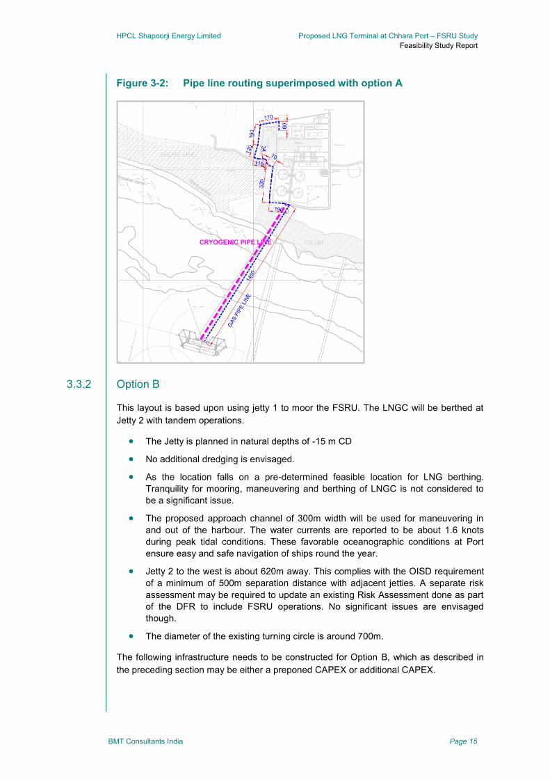
HPCL Shapoorji Energy Limited Proposed LNG Terminal at Chhara Port – FSRU Study
Feasibility Study Report
BMT Consultants India Page 15
Figure 3-2: Pipe line routing superimposed with option A
3.3.2 Option B
This layout is based upon using jetty 1 to moor the FSRU. The LNGC will be berthed at
Jetty 2 with tandem operations.
The Jetty is planned in natural depths of -15 m CD
No additional dredging is envisaged.
As the location falls on a pre-determined feasible location for LNG berthing.
Tranquility for mooring, maneuvering and berthing of LNGC is not considered to
be a significant issue.
The proposed approach channel of 300m width will be used for maneuvering in
and out of the harbour. The water currents are reported to be about 1.6 knots
during peak tidal conditions. These favorable oceanographic conditions at Port
ensure easy and safe navigation of ships round the year.
Jetty 2 to the west is about 620m away. This complies with the OISD requirement
of a minimum of 500m separation distance with adjacent jetties. A separate risk
assessment may be required to update an existing Risk Assessment done as part
of the DFR to include FSRU operations. No significant issues are envisaged
though.
The diameter of the existing turning circle is around 700m.
The following infrastructure needs to be constructed for Option B, which as described in
the preceding section may be either a preponed CAPEX or additional CAPEX.
CRYOGENIC PIPE LINE
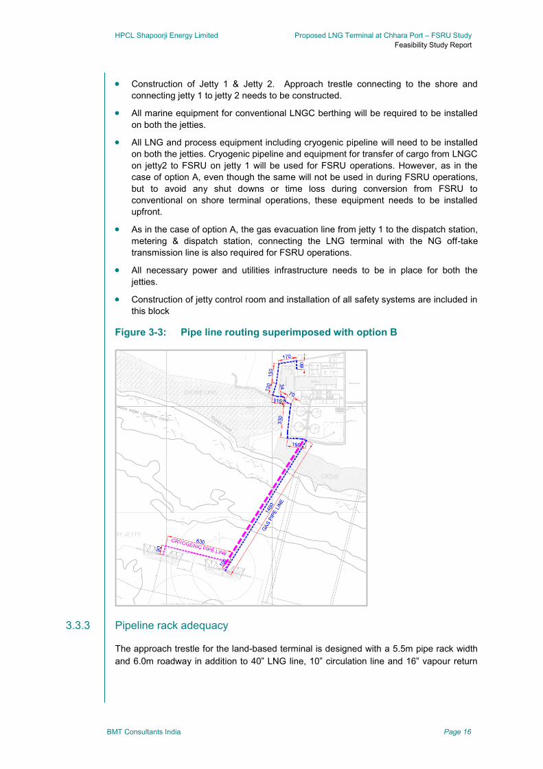
HPCL Shapoorji Energy Limited Proposed LNG Terminal at Chhara Port – FSRU Study
Feasibility Study Report
BMT Consultants India Page 16
Construction of Jetty 1 & Jetty 2. Approach trestle connecting to the shore and
connecting jetty 1 to jetty 2 needs to be constructed.
All marine equipment for conventional LNGC berthing will be required to be installed
on both the jetties.
All LNG and process equipment including cryogenic pipeline will need to be installed
on both the jetties. Cryogenic pipeline and equipment for transfer of cargo from LNGC
on jetty2 to FSRU on jetty 1 will be used for FSRU operations. However, as in the
case of option A, even though the same will not be used in during FSRU operations,
but to avoid any shut downs or time loss during conversion from FSRU to
conventional on shore terminal operations, these equipment needs to be installed
upfront.
As in the case of option A, the gas evacuation line from jetty 1 to the dispatch station,
metering & dispatch station, connecting the LNG terminal with the NG off-take
transmission line is also required for FSRU operations.
All necessary power and utilities infrastructure needs to be in place for both the
jetties.
Construction of jetty control room and installation of all safety systems are included in
this block
Figure 3-3: Pipe line routing superimposed with option B
3.3.3 Pipeline rack adequacy
The approach trestle for the land-based terminal is designed with a 5.5m pipe rack width
and 6.0m roadway in addition to 40” LNG line, 10” circulation line and 16” vapour return
HPCL Shapoorji Energy Limited Proposed LNG Terminal at Chhara Port – FSRU Study
Feasibility Study Report
BMT Consultants India Page 17
line. In addition to these lines, the rack may host other utility pipelines and power &
control cables.
For the FSRU project, an additional gas pipeline would be required to be added to the
rack. We estimate that a 22-inch diameter gas pipeline would be sufficient for transferring
2.5 mtpa of RLNG from the jetties to the gas dispatch station located on land. This
pipeline is sized conservatively so as to have adequate capacity even at lower
regasification pressure of 50 barg. However, in favour of keeping adequate pipeline
capacity, we recommend 26-inch pipeline, which would be adequate for transferring 3.5
mtpa of RLNG.
Given the available width of the pipe rack on the trestle, we estimate that the gas pipeline
could be easily accommodated, and no additional design changes are required with
respect to the pipe rack and trestle.
Infrastructure requirements 3.4
Development and requirement for infrastructure development and equipment installation
for each option has been assessed. For the sake of clarity and assessment, the
investment requirement has been categorised into following sections;
Shared investment – Block 1
Additional investment– Block 2
Operational expenditure– Block 3
3.4.1 Shared investment –Block 1
The infrastructure & equipment required by FSRU terminal that are common with land-
based terminal phase-1, as well as those which are required to be advanced for
eliminating delays in switchover to land-based terminal, are a part of this block. These
facilities have to be preponed because they are required for FSRU terminal operations
(e.g. trestle). During regular operations on the FSRU, due to restriction affected due to
the exclusion zone (to be determined during the QRA), no hot works will be allowed within
the said zone, therefore resulting in no construction works possible on the jetty and some
part of the trestle during FSRU operations. Therefore, in order to eliminate the
construction downtime during FSRU to land-based terminal switchover (e.g. Cryogenic
pipeline, LNG unloading arms, safety equipment, etc on the jetty and trestle) The major
heads in this block are as below:
Marine civil works
Jetty
Approach trestle
Jetty control room and all safety systems
Marine equipment
Fenders
Mooring hooks
Jetty control room monitoring equipment
HPCL Shapoorji Energy Limited Proposed LNG Terminal at Chhara Port – FSRU Study
Feasibility Study Report
BMT Consultants India Page 18
Environment monitoring station
Etc.
Process equipment
LNG arms
LNG pipeline
Gas dispatch
Power infrastructure
Marine civil works
The marine Jetty-1 and the trestle connecting it to the land are included in this head.
Related marine infrastructure such as connecting road, pipe-rack, jetty
superstructure, etc. is included.
Construction of the jetty control room and installation of all safety systems are
included in this block
Marine equipment
All the marine equipment located on Jetty-1, required for proper functioning of the
FSRU marine operations fall under this head. Marine equipment such as mooring
system, navigational system, fendering arrangements on the jetty and other relevant
marine equipment are included. Jetty based utilities & systems such as fire-water
system, pumps, power panels, compressors etc. are included.
Process equipment
LNG arms are used for ship-to-shore connection for LNG unloading. Generally these
are a set of 4-5 arms which are used for LNG unloading as well as vapour balancing.
We have considered a set of 4 LNG arms based on the DFR information as well as
related control and monitoring systems, located on Jetty-1 within this head.
Although, in option A the LNG arms and associated utilities may not be required for
FSRU operations on Jetty 1, but in order to eliminate the construction downtime
during FSRU to land-based terminal switchover, it is recommended to install all jetty
based equipment upfront.
LNG Equipment such as, knock-out drum, nitrogen units, control & monitoring
sensors, control system, valves, desuperheater, etc. which are located on the Jetty-1
before the LNG pipeline flange are included in this head.
Although, the LNG arms and associated utilities may not be required for FSRU
operations on Jetty 1, but in order to eliminate the construction downtime during the
FSRU to land-based terminal switchover, it is recommended to install all jetty based
equipment upfront.
The LNG pipeline from the Jetty-1 across the trestle up to the land fall point is
considered here. The distance between Jetty-1 and the land fall point is about
1120m. The head also includes related lines such as vapour-balancing line, re-
circulation line etc.
Installation of LNG pipelines on the jetty and part of the trestle falling under the safety
and exclusion zone (300 m) of unloading operations are a minimum to be considered
being constructed upfront. For the sake of this study, we have considered installation
of the pipe line on the entire length of the trestle, i.e. about 1120m.

HPCL Shapoorji Energy Limited Proposed LNG Terminal at Chhara Port – FSRU Study
Feasibility Study Report
BMT Consultants India Page 19
Gas dispatch and gas metering station, connecting the LNG terminal with the NG
off-take transmission line is also required for FSRU operations.
Power infrastructure
Jetty operations will require power connection. Though the FSRU will generate its
own power, the jetty based equipment, pumps and control system will require
external power. Though this does NOT require construction of a power substation as
envisaged for the land-based terminal, suitable scaled-down power infrastructure will
still be required.
Table 3-1: Block 1 infrstructure requirements
Block Sub-heads Option A Option B
BLO
CK
1 :
SH
AR
ED
INV
ES
TM
EN
T
Trestle & Jetty ● ●
Marine equipment ● ●
LNG arms ● ●
LNG equipment ● ●
LNG pipeline ● ●
Gas dispatch ● ●
Power infrastructure ● ●
Jetty control room and all safety system ● ●
LEGEND ○ Not Applicable
● Applicable
3.4.2 Additional investment block – Block 2
The infrastructure & equipment required by FSRU terminal which are additional to land-
based terminal phase-1, are a part of this block. Major heads are as follow:
Marine civil works
Jetty
Approach trestle
Jetty control room and all safety systems
Marine equipment
Fenders
Mooring hooks
Jetty control room monitoring equipment
Environment monitoring station
Etc.
Process equipment
LNG arms
HPCL Shapoorji Energy Limited Proposed LNG Terminal at Chhara Port – FSRU Study
Feasibility Study Report
BMT Consultants India Page 20
Ship-to-ship LNG Hose
LNG pipeline
NG Arm & equipment
Gas dispatch
Marine civil works
Option-A requires construction of two additional mooring dolphins in addition to the
existing mooring infrastructure, in order to evenly distribute mooring loads during ship-to-
ship mooring operations. Additionally, subject to detailed design review, an additional
platform may be required to be constructed for mounting on the high-pressure NG arm.
However, on conservative basis, we have included its cost in our estimates.
Option-B required Jetty-2 to be constructed upfront. Since Jetty-2 is not part of Phase-1
of the land-based terminal plan, Jetty-2 and the connecting trestle will be additional.
Related marine infrastructure cost such as connecting road, pipe-rack, jetty
superstructure, control room, etc. for Jetty-2 are included.
Marine equipment
Option-A, involves ship-to-ship mooring & operations. Therefore, slight up gradation in
marine equipment is required. We estimate additional requirement of two QRMH and up
gradation of the existing four QRMH for greater mooring loads. Up gradation of pneumatic
fender design and additional four foam-type fenders are estimated as required.
In Option-B all the marine equipment, systems and utilities located at Jetty-2 are
considered as additional. However, similar equipment, systems and utilities located on
Jetty-1 are considered under the Block 1.
Process equipment
LNG arms:
Option-A does not require LNG arms during FSRU operations. However, no construction
& erection work is possible during FSRU operations within the exclusion zone (likely to be
in the order of 500 m). Therefore, in order to avoid downtime during FSRU to land-based
terminal changeover, all the jetty based equipment has to be erected and commissioned
before the FSRU berths at the Jetty-1. Since these arms are a part of Block-1, we do not
consider these in Block-2 estimates.
In Option-B, the set of LNG arms located on Jetty-2 are considered as additional. As the
jetty drawings indicate 4-arm set, we have considered this as the benchmark for our
assessment. We have considered the set of LNG arms as well as related control and
monitoring systems within this head.
LNG equipment:
All LNG equipment located on Jetty-1 in Option-A are included in Block-1.
Option-B additionally requires all the LNG equipment such as LNG header, knock-out
drum, nitrogen units, control & monitoring sensors, control system, valves,
HPCL Shapoorji Energy Limited Proposed LNG Terminal at Chhara Port – FSRU Study
Feasibility Study Report
BMT Consultants India Page 21
desuperheater, etc. located on the Jetty-2. The costs for these are considered as
additional investment in Block-2.
LNG Pipeline:
In Option-A, LNG pipeline across the trestle up to land-fall point is considered in Block-1.
No additional pipeline costs are estimated in this option.
LNG pipeline across the connecting trestle between Jetty-1 and Jetty2 is considered
additional in Option-B. We have considered an additional 700m of cryogenic LNG pipeline
for our assessment. The head also includes related lines such as the vapour-balancing
line, re-circulation line etc.
LNG hoses:
In Option-A, the FSRU and LNGC will be alongside moored. This arrangement will
require LNG to be directly transferred between the LNGC and FSRU, where either LNG
arms can be mounted on the FSRU, or flexible hose can be used. Mounting LNG Arms
on the FSRU is not recommended as these arms are permanently mounted on the FSRU
vessel and will sail-away along with the FSRU when the lease-term ends. Instead, flexible
hoses can be used for LNG transfer. The only drawback for the hoses is lower LNG
transfer rates, which may result in slightly longer berthing time for the visiting LNGC.
Alternatively, hard arms can also be placed on the FSRU for cargo transfer, but bearing in
mind that a short term lease is envisaged. It is considered difficult for a FSRU supplier to
make such modifications. Therefore, we have considered LNG hoses as the cargo
transfer conduits in Ship-To-Ship (STS) operations. Typically some FSRU suppliers have
a set such cryogenic hoses on board their FSRU. Therefore, the additional CAPEX for
such LNG hose connectors would be subject to availability with the FSRU supplier.
However, we have conservatively included costs for such hoses in our estimates.
Option-B does not require any such arrangement as the LNG will be transferred by LNG
Arms.
NG arms;
Both the options, Option-A and Option-B, require high pressure NG arms as ship-to-shore
connection required for dispatching RLNG from the FSRU to the shore. Generally a single
arm is suitable for handling high pressure gas up to 100 Bar. We have considered all
associated equipment, control and monitoring systems within this head in both the
options. FSRU operations are recommended to be carried out on Jetty 1 only, and
therefore NG arms would be required on or near jetty 1 only for both the options.
Gas pipe line:
A common high pressure gas pipeline starting from the NG Arm, travelling across the
trestle towards shore, across the land reaching the gas metering & dispatch station is
required in both the options, Option-A and Option-B. Considering the gas pipeline route
from the Jetty-1 to the gas dispatch, we have considered a gas pipe line of 26” diameter
and length of about 3,000m for our cost assessment. All associated monitoring, control
and maintenance equipment such as sensors, valves, protection, etc. are included. This

HPCL Shapoorji Energy Limited Proposed LNG Terminal at Chhara Port – FSRU Study
Feasibility Study Report
BMT Consultants India Page 22
will be required for both the options. As explained above, since NG arms are located on
jetty 1, the gas pipe line length would be same for both the options.
Table 3-2: Block 2 infrstructure requirements
Block Sub-heads Option A Option B
Blo
ck 2
: A
DD
ITIO
NA
L IN
FR
ST
RU
CT
UR
E
Trestle & Jetty ● ●
Marine equipment ● ●
LNG arms ○ ●
LNG equipment ○ ●
LNG pipeline ○ ●
STS LNG hose ● ○
NG arm and equipment ● ●
Gas pipe line ● ●
LEGEND ○ Not Applicable
● Applicable
3.4.3 Operational expenditure (OPEX)
Operation & maintenance expenditure for all infrastructure & equipment in Block 1 &
Block 2 are a part of this block. This has been dealt in detail in the cost assessment
section. OPEX is estimated on block cost basis and is divided into the following heads:
FSRU charter
Regas cost
Terminal O&M
Additionally, we have also estimated a block cost for preservation or scrapping cost
estimates for Block-2 additional Equipment which will be redundant after the on land LNG
terminal is commissioned.
FSRU charter
Considering the requirement of a FSRU as a bridging arrangement for early
commissioning of the LNG terminal by 2-3 years, it is envisaged that the FSRU will be
procured on lease arrangement basis. As per short-lease requirement of the project,
lease arrangement will be essentially a time-charter agreement, where the supplier will
supply the FSRU vessel inclusive of ship-management arrangements
HPCL Shapoorji Energy Limited Proposed LNG Terminal at Chhara Port – FSRU Study
Feasibility Study Report
BMT Consultants India Page 23
Internal Gas consumption
FSRU uses gas for regasification operations as well for its own energy requirements. The
internal gas consumption of the FSRU is dependent on the regasification scheme (closed
loop vs. open loop) and broadly proportional to the terminal throughput.
Terminal O & M
The O&M costs associated with the process (topside) infrastructure & equipment required
for the FSRU terminal is included in this head. Costs related to preservation of early
commissioned equipment which may not be used during FSRU operations (eg. LNG arms
in Option-A) are also included. The power consumption of the FSRU terminal is assumed
to be supplied from shore based power infrastructure, the cost of which is included in this
head.
The O&M costs associated with all the marine infrastructure & equipment required for the
FSRU terminal are included in this head.
Insurance
The insurance for the terminal infrastructure as well as the cargo is assumed to be
considered in the overall project costing. However, the insurance for FSRU as an asset is
considered included in the charter lease.
HPCL Shapoorji Energy Limited Proposed LNG Terminal at Chhara Port – FSRU Study
Feasibility Study Report
BMT Consultants India Page 24
4 FSRU availability and sizing
FSRU availability 4.1
A FSRU is essentially a LNG Carrier which has been modified and fitted with LNG
regasification and high pressure Natural Gas dispatch systems. It is generally capable of
simultaneously receiving LNG into its cargo tanks and sending out high pressure Natural
Gas. It may be permanently moored to a port-based or offshore anchored jetty. Given the
asset utilization flexibility, short decision to commissioning timeframe, and attractive
leasing arrangements offered by major suppliers, FSRU concept has become popular
with many terminal developers considering it as a viable alternative to land based
configuration.
Awareness about floating LNG terminal solution has been increasing over the past
decade. It is estimated that there are more than 30 FSRU based terminals are at various
stages of development, and about 11 of them are already operational. As the number of
floating terminals and the operating experience increase, there is bound to be greater
requirement for FSRU ships.
Most of the large LNG shippers have entered into FSRU construction options with
shipyards. For instance, Golar has an expansion plan with 13 additional new-build
FSRUs, while Excelerate Energy has shipbuilding options for 8 additional new-built
FSRUs. Also most large suppliers generally follow a strategy of having at least one
uncommitted FSRU available for short-delivery commissioning, thereby giving them a
time advantage. These they may exercise as their outlook matures.
Given this degree of activity in the FSRU market, the availability remains volatile with
respect to demand-supply scenario. Therefore, it is recommended that all the suppliers
may be contacted to seek availability for potential FSRU supply.
FSRU fleet 4.2
The major shipping companies own these FSRUs worldwide. In this section a brief
description of each of the available FSRU categorised by their ownership/operatorship is
provided. The description is limited to the following companies.
Golar LNG
Hoegh LNG
Excelerate Energy
BW Gas
Others
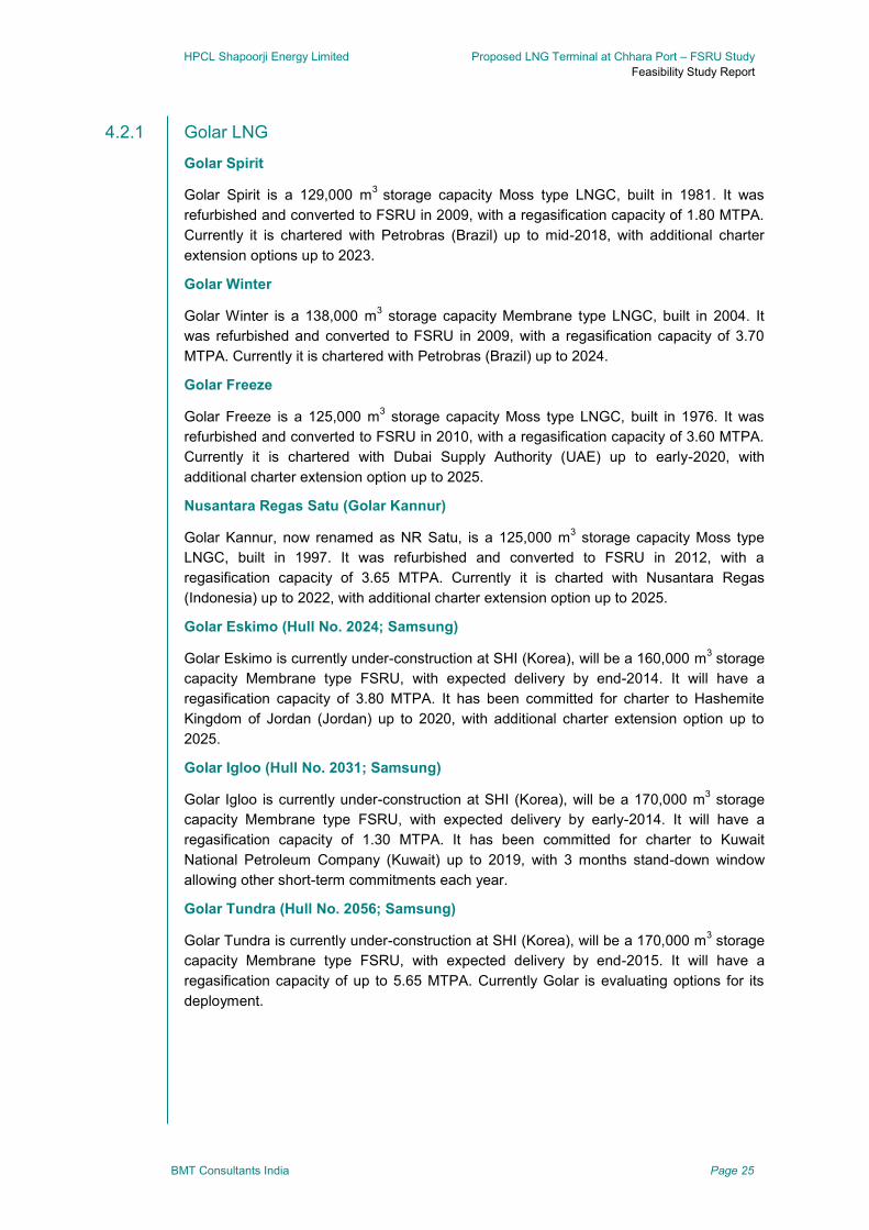
HPCL Shapoorji Energy Limited Proposed LNG Terminal at Chhara Port – FSRU Study
Feasibility Study Report
BMT Consultants India Page 25
4.2.1 Golar LNG
Golar Spirit
Golar Spirit is a 129,000 m3
storage capacity Moss type LNGC, built in 1981. It was
refurbished and converted to FSRU in 2009, with a regasification capacity of 1.80 MTPA.
Currently it is chartered with Petrobras (Brazil) up to mid-2018, with additional charter
extension options up to 2023.
Golar Winter
Golar Winter is a 138,000 m3 storage capacity Membrane type LNGC, built in 2004. It
was refurbished and converted to FSRU in 2009, with a regasification capacity of 3.70
MTPA. Currently it is chartered with Petrobras (Brazil) up to 2024.
Golar Freeze
Golar Freeze is a 125,000 m3 storage capacity Moss type LNGC, built in 1976. It was
refurbished and converted to FSRU in 2010, with a regasification capacity of 3.60 MTPA.
Currently it is chartered with Dubai Supply Authority (UAE) up to early-2020, with
additional charter extension option up to 2025.
Nusantara Regas Satu (Golar Kannur)
Golar Kannur, now renamed as NR Satu, is a 125,000 m3 storage capacity Moss type
LNGC, built in 1997. It was refurbished and converted to FSRU in 2012, with a
regasification capacity of 3.65 MTPA. Currently it is charted with Nusantara Regas
(Indonesia) up to 2022, with additional charter extension option up to 2025.
Golar Eskimo (Hull No. 2024; Samsung)
Golar Eskimo is currently under-construction at SHI (Korea), will be a 160,000 m3 storage
capacity Membrane type FSRU, with expected delivery by end-2014. It will have a
regasification capacity of 3.80 MTPA. It has been committed for charter to Hashemite
Kingdom of Jordan (Jordan) up to 2020, with additional charter extension option up to
2025.
Golar Igloo (Hull No. 2031; Samsung)
Golar Igloo is currently under-construction at SHI (Korea), will be a 170,000 m3 storage
capacity Membrane type FSRU, with expected delivery by early-2014. It will have a
regasification capacity of 1.30 MTPA. It has been committed for charter to Kuwait
National Petroleum Company (Kuwait) up to 2019, with 3 months stand-down window
allowing other short-term commitments each year.
Golar Tundra (Hull No. 2056; Samsung)
Golar Tundra is currently under-construction at SHI (Korea), will be a 170,000 m3 storage
capacity Membrane type FSRU, with expected delivery by end-2015. It will have a
regasification capacity of up to 5.65 MTPA. Currently Golar is evaluating options for its
deployment.
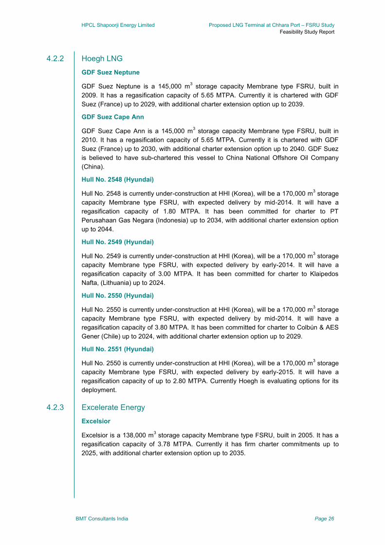
HPCL Shapoorji Energy Limited Proposed LNG Terminal at Chhara Port – FSRU Study
Feasibility Study Report
BMT Consultants India Page 26
4.2.2 Hoegh LNG
GDF Suez Neptune
GDF Suez Neptune is a 145,000 m3 storage capacity Membrane type FSRU, built in
2009. It has a regasification capacity of 5.65 MTPA. Currently it is chartered with GDF
Suez (France) up to 2029, with additional charter extension option up to 2039.
GDF Suez Cape Ann
GDF Suez Cape Ann is a 145,000 m3 storage capacity Membrane type FSRU, built in
2010. It has a regasification capacity of 5.65 MTPA. Currently it is chartered with GDF
Suez (France) up to 2030, with additional charter extension option up to 2040. GDF Suez
is believed to have sub-chartered this vessel to China National Offshore Oil Company
(China).
Hull No. 2548 (Hyundai)
Hull No. 2548 is currently under-construction at HHI (Korea), will be a 170,000 m3 storage
capacity Membrane type FSRU, with expected delivery by mid-2014. It will have a
regasification capacity of 1.80 MTPA. It has been committed for charter to PT
Perusahaan Gas Negara (Indonesia) up to 2034, with additional charter extension option
up to 2044.
Hull No. 2549 (Hyundai)
Hull No. 2549 is currently under-construction at HHI (Korea), will be a 170,000 m3 storage
capacity Membrane type FSRU, with expected delivery by early-2014. It will have a
regasification capacity of 3.00 MTPA. It has been committed for charter to Klaipedos
Nafta, (Lithuania) up to 2024.
Hull No. 2550 (Hyundai)
Hull No. 2550 is currently under-construction at HHI (Korea), will be a 170,000 m3 storage
capacity Membrane type FSRU, with expected delivery by mid-2014. It will have a
regasification capacity of 3.80 MTPA. It has been committed for charter to Colbún & AES
Gener (Chile) up to 2024, with additional charter extension option up to 2029.
Hull No. 2551 (Hyundai)
Hull No. 2550 is currently under-construction at HHI (Korea), will be a 170,000 m3 storage
capacity Membrane type FSRU, with expected delivery by early-2015. It will have a
regasification capacity of up to 2.80 MTPA. Currently Hoegh is evaluating options for its
deployment.
4.2.3 Excelerate Energy
Excelsior
Excelsior is a 138,000 m3 storage capacity Membrane type FSRU, built in 2005. It has a
regasification capacity of 3.78 MTPA. Currently it has firm charter commitments up to
2025, with additional charter extension option up to 2035.
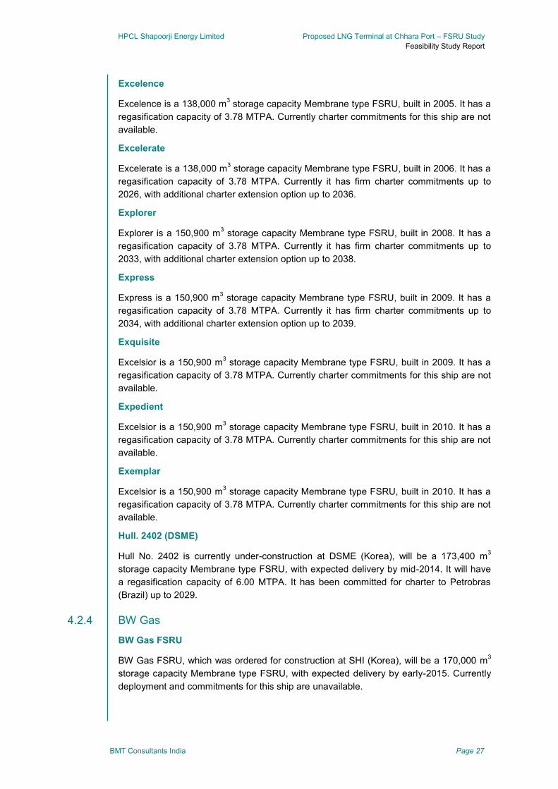
HPCL Shapoorji Energy Limited Proposed LNG Terminal at Chhara Port – FSRU Study
Feasibility Study Report
BMT Consultants India Page 27
Excelence
Excelence is a 138,000 m3 storage capacity Membrane type FSRU, built in 2005. It has a
regasification capacity of 3.78 MTPA. Currently charter commitments for this ship are not
available.
Excelerate
Excelerate is a 138,000 m3 storage capacity Membrane type FSRU, built in 2006. It has a
regasification capacity of 3.78 MTPA. Currently it has firm charter commitments up to
2026, with additional charter extension option up to 2036.
Explorer
Explorer is a 150,900 m3 storage capacity Membrane type FSRU, built in 2008. It has a
regasification capacity of 3.78 MTPA. Currently it has firm charter commitments up to
2033, with additional charter extension option up to 2038.
Express
Express is a 150,900 m3 storage capacity Membrane type FSRU, built in 2009. It has a
regasification capacity of 3.78 MTPA. Currently it has firm charter commitments up to
2034, with additional charter extension option up to 2039.
Exquisite
Excelsior is a 150,900 m3 storage capacity Membrane type FSRU, built in 2009. It has a
regasification capacity of 3.78 MTPA. Currently charter commitments for this ship are not
available.
Expedient
Excelsior is a 150,900 m3 storage capacity Membrane type FSRU, built in 2010. It has a
regasification capacity of 3.78 MTPA. Currently charter commitments for this ship are not
available.
Exemplar
Excelsior is a 150,900 m3 storage capacity Membrane type FSRU, built in 2010. It has a
regasification capacity of 3.78 MTPA. Currently charter commitments for this ship are not
available.
Hull. 2402 (DSME)
Hull No. 2402 is currently under-construction at DSME (Korea), will be a 173,400 m3
storage capacity Membrane type FSRU, with expected delivery by mid-2014. It will have
a regasification capacity of 6.00 MTPA. It has been committed for charter to Petrobras
(Brazil) up to 2029.
4.2.4 BW Gas
BW Gas FSRU
BW Gas FSRU, which was ordered for construction at SHI (Korea), will be a 170,000 m3
storage capacity Membrane type FSRU, with expected delivery by early-2015. Currently
deployment and commitments for this ship are unavailable.

HPCL Shapoorji Energy Limited Proposed LNG Terminal at Chhara Port – FSRU Study
Feasibility Study Report
BMT Consultants India Page 28
4.2.5 OLT Offshore
FSRU Toscana (Golar Frost)
Golar Frost, now renamed as FSRU Toscana, is a 137,000 m3 storage capacity Moss
type LNGC, built in 2004. It was refurbished and converted to FSRU in 2012, with a
regasification capacity of 3.75 MTPA. Currently it is owned by OLT Offshore (Italy) as a
dedicated asset for Livorno Offshore project.
4.2.6 Others LNG shippers
In addition to the above, large LNG shippers such as Teekay, MOL and other have shown
interest in supplying FSRU to various project proponents. In addition, IHI of Japan also
provide FSRUs.
FSRU sizing 4.3
As seen from the above, FSRUs come in different sizes. Typically the LNGCs which have
been refurbished and converted into FSRU have low storage capacity, while the FSRUs
which are new-built have greater LNG storage capacity.
The storage capacity vs. World LNG Fleet is as given below, with the above mentioned
FSRUs marked.
Figure 4-1: Storage Capacity (m3) vs. World LNG Fleet
Summary of the available FSRUs and their characteristics is provided in the table below.
~ 135,000 m3
~ 170,000 m3

HPCL Shapoorji Energy Limited Proposed LNG Terminal at Chhara Port – FSRU Study
Feasibility Study Report
BMT Consultants India Page 29
Table 4-1: Summary of FSRU fleet
Sr. No. Operator FSRU Identification Hull
(Year)
Storage
(m3)
Regas
(MTPA) Committed to…
Com.
Up to
1 Golar Golar Spirit 1981 129,000 1.80 Petrobras, Brazil 2023
2 Golar Golar Winter 2004 138,000 3.70 Petrobras, Brazil 2024
3 Golar Golar Freeze 1976 125,000 3.60 DSA, UAE 2025
4 Golar NR Satu 1997 125,000 3.65 NR Gas, Indonesia 2025
5 Golar Golar Eskimo (SHI) 2014E 160,000 3.80 Kingdom of Jordan 2025
6 Golar Golar Igloo (SHI) 2014E 170,000 1.30 KNPC, Kuwait 2019
7 Golar Golar Tundra (SHI) 2015E 170,000 5.65 Open N/a
8 Hoegh GDF Suez Neptune 2009 145,000 5.65 GDF Suez, France 2029
9 Hoegh GDF Suez Cape Ann 2010 145,000 5.65 GDF Suez, France 2030
10 Hoegh Hull 2548 (HHI) 2014E 170,000 1.80 PT Perusahaan Gas Negara, Indonesia
2044
11 Hoegh Hull 2549 (HHI) 2014E 170,000 3.00 Klaipedos Nafta, Lithuania
2024
12 Hoegh Hull 2550 (HHI) 2014E 170,000 3.80 Colbun & AES Gener, Chile
2029
13 Hoegh Hull 2551 (HHI) 2015E 170,000 2.80 Open N/a
14 Excelerate Excelsior 2005 138,000 3.78 Not Available 2035
15 Excelerate Excelence 2005 138,000 3.78 Not Available N/a
16 Excelerate Excelerate 2006 138,000 3.78 Not Available 2036
17 Excelerate Explorer 2008 150,900 3.78 Not Available 2038
18 Excelerate Express 2009 150,900 3.78 Not Available 2034
19 Excelerate Exquisite 2010 150,900 3.78 Not Available N/a
20 Excelerate Expedient 2010 150,900 3.78 Not Available N/a
21 Excelerate Exemplar 2010 150,900 3.78 Not Available N/a
22 Excelerate Hull 2402 (DSME) 2014E 173,400 6.00 Petrobras, Brazil 2029
23 BW Gas BW Gas FSRU 2015E 170,000 N/a Open N/a
24 OLT Offshore
FSRU Toscana 2012 137,000 3.75 OLT Offshore, Italy N/a
Summary 4.4
Range of FSRU size availability falls between 135,000 m3 to 170,000 m
3 as highlighted in
the above graphic. Given the overall trend for large storage capacity new-built FSRUs, for
the purpose of this study, design vessel size of 150,000 m3 with a re-gas capacity of 2.5-3
MTPA has been considered. The technical design and cost estimates will also include
possibility of berthing larger FSRU up to 170,000 m3 capacity.
Generic specifications of design vessel for FSRU (150,000 m3 to 170,000 m
3) is as below.
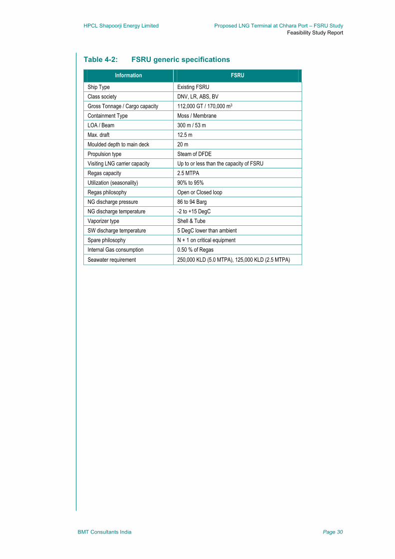
HPCL Shapoorji Energy Limited Proposed LNG Terminal at Chhara Port – FSRU Study
Feasibility Study Report
BMT Consultants India Page 30
Table 4-2: FSRU generic specifications
Information FSRU
Ship Type Existing FSRU
Class society DNV, LR, ABS, BV
Gross Tonnage / Cargo capacity 112,000 GT / 170,000 m3
Containment Type Moss / Membrane
LOA / Beam 300 m / 53 m
Max. draft 12.5 m
Moulded depth to main deck 20 m
Propulsion type Steam of DFDE
Visiting LNG carrier capacity Up to or less than the capacity of FSRU
Regas capacity 2.5 MTPA
Utilization (seasonality) 90% to 95%
Regas philosophy Open or Closed loop
NG discharge pressure 86 to 94 Barg
NG discharge temperature -2 to +15 DegC
Vaporizer type Shell & Tube
SW discharge temperature 5 DegC lower than ambient
Spare philosophy N + 1 on critical equipment
Internal Gas consumption 0.50 % of Regas
Seawater requirement 250,000 KLD (5.0 MTPA), 125,000 KLD (2.5 MTPA)

HPCL Shapoorji Energy Limited Proposed LNG Terminal at Chhara Port – FSRU Study
Feasibility Study Report
BMT Consultants India Page 31
5 Marine assessment
The fundamental requirement for the terminal is for vessels to be able to enter and depart
safely and, once berthed, to remain alongside for long enough to safely load or discharge
their car-go. Additionally, for FSRU, since the vessel is to be kept in moored condition for
a long time, environment persistence is necessary to be understood for safe and
uninterrupted operations. Consequently, all relevant site-specific issues which could
affect a ship’s navigation and mooring must be taken into account. These include:
Marine access for the vessel, including suitable turning/manoeuvring areas near the
berth
Suitable anchorage area(s)
Provision of adequate navigation aids, VTS, tugs and pilots
Sufficiently deep, protected water for the berth, to allow the vessel to safely moor and
to load/discharge cargo
Nature of the seabed and requirements for capital and maintenance dredging
Tidal range
Prevailing current, sea and weather conditions and the orientation of berths
Passing ships
Impact/conflict with other port traffic
Security and unauthorised craft
Proximity to population centres
Environmental impact issues
Hazardous zones analysis
This section describes assessment of the layout options from the marine navigation and
safety perspective. Broad based assessment has been carried out under the following
heads:
Mooring layout assessment
Docking and mooring systems
Fendering requirements
Navigation requirements
Mooring layout assessment 5.1
Proposed mooring layout is assessed for both the options. The design philosophy for the
initial assessment of the mooring and berthing layout was based on the relevant
guidelines published by the Oil Companies International Marine Forum (OCIMF
guidelines – 2nd edition 1997) and relevant BS Codes. The main principles of the
philosophy considered were as follows:
HPCL Shapoorji Energy Limited Proposed LNG Terminal at Chhara Port – FSRU Study
Feasibility Study Report
BMT Consultants India Page 32
5.1.1 Dolphin spacing
breasting (fender) dolphin spacing: 25% to 40% of LOA, to locate on parallel body
side
inner mooring dolphin spacing: 80% LOA
Outer mooring dolphin spacing: 135% LOA.
5.1.2 Mooring dolphin set-back
The design philosophy for the layout of berthing and mooring dolphins has been
optimised based upon OCIMF guidelines.
As a standard recommendation, 35-50 m setback shall be used.
However, more rigorous and detailed computational analyses for mooring, berthing / de-
berthing, navigation, etc. should be undertaken during the detailed design stage to
optimise the set-back value.
5.1.3 Mooring line angle criteria
Head / stern lines: Head stern lines are not normally efficient in restraining a ship on
its berth due to their longer lengths and there can be a
requirement for two additional outer mooring dolphins to be
provided. Latest industry practice advocates that mooring facilities
with good breast and spring lines should allow a ship to be
moored virtually within its own length. Head and stern lines can be
used if special pier geometry is encountered or there are large
surge forces or unexpectedly severe weather conditions.
Breasting lines: Line angles 10° to 15
° on plan (as perpendicular as possible and
as far forward and aft as possible). If lines are too normal to the
stern of the ship, then there is the possibility of lines breaking
across it, which should be avoided.
Spring lines: Line angles 80° to 90
° to the breasting / mooring dolphin on plan
(as parallel to the vessel as possible).
Vertical angles: Lines run as close to the horizontal as possible (maximum 25°
upwards)
Vessels with highly eccentric manifold positions may require special arrangements.
Two alternative layouts were considered in this layout assessment for option A and option
B. Mooring layout available as part of the DFR studies have been adopted for further
assessment and investigation of adequacy of the same for FSRU operations. The layout
provided by client was assessed for the berthing and mooring of FSRU.
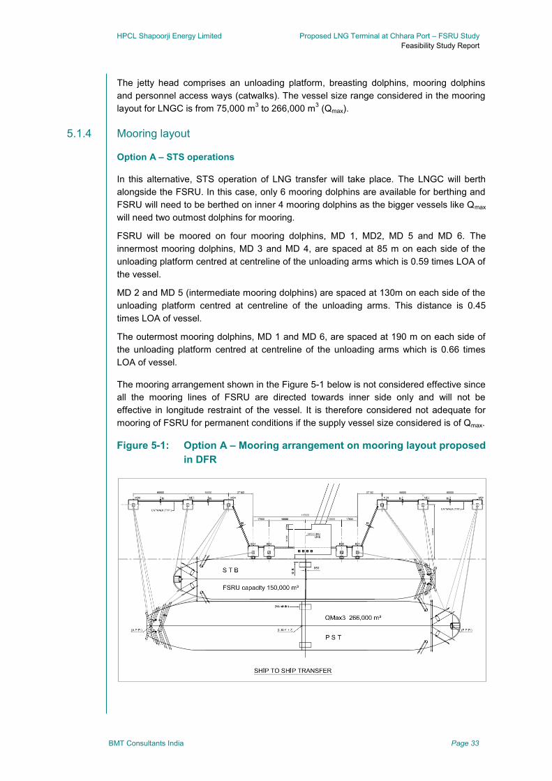
HPCL Shapoorji Energy Limited Proposed LNG Terminal at Chhara Port – FSRU Study
Feasibility Study Report
BMT Consultants India Page 33
The jetty head comprises an unloading platform, breasting dolphins, mooring dolphins
and personnel access ways (catwalks). The vessel size range considered in the mooring
layout for LNGC is from 75,000 m3 to 266,000 m
3 (Qmax).
5.1.4 Mooring layout
Option A – STS operations
In this alternative, STS operation of LNG transfer will take place. The LNGC will berth
alongside the FSRU. In this case, only 6 mooring dolphins are available for berthing and
FSRU will need to be berthed on inner 4 mooring dolphins as the bigger vessels like Qmax
will need two outmost dolphins for mooring.
FSRU will be moored on four mooring dolphins, MD 1, MD2, MD 5 and MD 6. The
innermost mooring dolphins, MD 3 and MD 4, are spaced at 85 m on each side of the
unloading platform centred at centreline of the unloading arms which is 0.59 times LOA of
the vessel.
MD 2 and MD 5 (intermediate mooring dolphins) are spaced at 130m on each side of the
unloading platform centred at centreline of the unloading arms. This distance is 0.45
times LOA of vessel.
The outermost mooring dolphins, MD 1 and MD 6, are spaced at 190 m on each side of
the unloading platform centred at centreline of the unloading arms which is 0.66 times
LOA of vessel.
The mooring arrangement shown in the Figure 5-1 below is not considered effective since
all the mooring lines of FSRU are directed towards inner side only and will not be
effective in longitude restraint of the vessel. It is therefore considered not adequate for
mooring of FSRU for permanent conditions if the supply vessel size considered is of Qmax.
Figure 5-1: Option A – Mooring arrangement on mooring layout proposed
in DFR
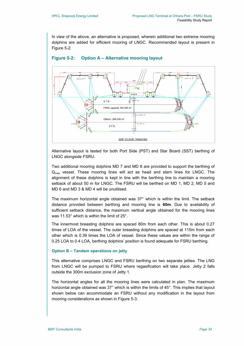
HPCL Shapoorji Energy Limited Proposed LNG Terminal at Chhara Port – FSRU Study
Feasibility Study Report
BMT Consultants India Page 34
In view of the above, an alternative is proposed, wherein additional two extreme mooring
dolphins are added for efficient mooring of LNGC. Recommended layout is present in
Figure 5-2.
Figure 5-2: Option A – Alternative mooring layout
Alternative layout is tested for both Port Side (PST) and Star Board (SST) berthing of
LNGC alongside FSRU.
Two additional mooring dolphins MD 7 and MD 8 are provided to support the berthing of
Qmax vessel. These mooring lines will act as head and stern lines for LNGC. The
alignment of these dolphins is kept in line with the berthing line to maintain a mooring
setback of about 50 m for LNGC. The FSRU will be berthed on MD 1, MD 2, MD 5 and
MD 6 and MD 3 & MD 4 will be unutilised.
The maximum horizontal angle obtained was 37° which is within the limit. The setback
distance provided between berthing and mooring line is 60m. Due to availability of
sufficient setback distance, the maximum vertical angle obtained for the mooring lines
was 11.53° which is within the limit of 25°.
The innermost breasting dolphins are spaced 80m from each other. This is about 0.27
times of LOA of the vessel. The outer breasting dolphins are spaced at 115m from each
other which is 0.39 times the LOA of vessel. Since these values are within the range of
0.25 LOA to 0.4 LOA, berthing dolphins’ position is found adequate for FSRU berthing.
Option B – Tandem operations on jetty
This alternative comprises LNGC and FSRU berthing on two separate jetties. The LNG
from LNGC will be pumped to FSRU where regasification will take place. Jetty 2 falls
outside the 300m exclusion zone of Jetty 1.
The horizontal angles for all the mooring lines were calculated in plan. The maximum
horizontal angle obtained was 37° which is within the limits of 45°. This implies that layout
shown below can accommodate an FSRU without any modification in the layout from
mooring considerations as shown in Figure 5-3.

HPCL Shapoorji Energy Limited Proposed LNG Terminal at Chhara Port – FSRU Study
Feasibility Study Report
BMT Consultants India Page 35
Figure 5-3: Option B – Tandem operations on adjacent jetties
In case of option B, the entire jetty construction, connecting approach trestle, topsides,
etc. will need to be brought forward in the overall project schedules, as this was originally
planned to be constructed in phase 2 of the development.
5.1.5 Gas discharge
The imported LNG from LNGC will be transferred to FSRU where regasification will take
place. The regasified LNG will be transferred to shore by high pressure gas discharge
flange on the vessel which is generally located at 30m c/c fore side of the manifold of the
vessel.
Placement of the HP gas loading arm on the jetty was investigated and two cases were
considered
FSRU berthing SST
FSRU berthing PST
FSRU berthing starboard side
In this case, the gas flange line falls between breasting dolphin and unloading platform.
An additional platform need to be constructed for unloading the regasified LNG.
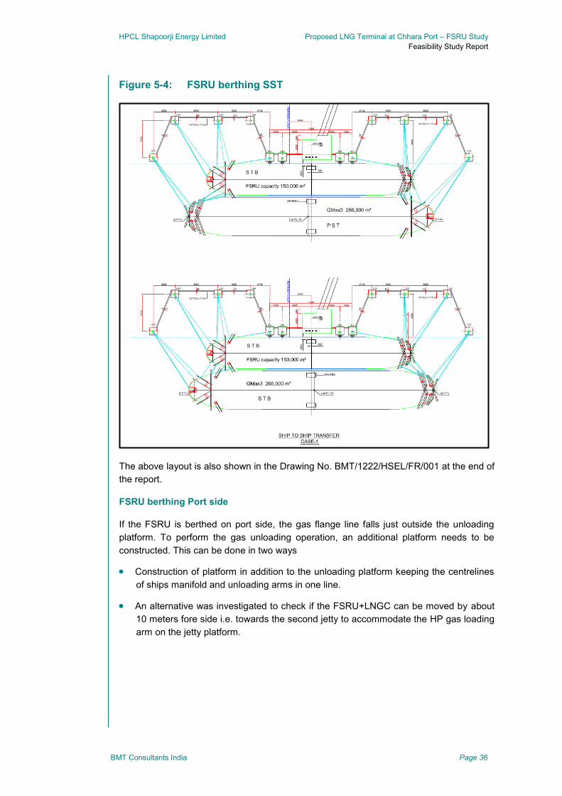
HPCL Shapoorji Energy Limited Proposed LNG Terminal at Chhara Port – FSRU Study
Feasibility Study Report
BMT Consultants India Page 36
Figure 5-4: FSRU berthing SST
The above layout is also shown in the Drawing No. BMT/1222/HSEL/FR/001 at the end of
the report.
FSRU berthing Port side
If the FSRU is berthed on port side, the gas flange line falls just outside the unloading
platform. To perform the gas unloading operation, an additional platform needs to be
constructed. This can be done in two ways
Construction of platform in addition to the unloading platform keeping the centrelines
of ships manifold and unloading arms in one line.
An alternative was investigated to check if the FSRU+LNGC can be moved by about
10 meters fore side i.e. towards the second jetty to accommodate the HP gas loading
arm on the jetty platform.
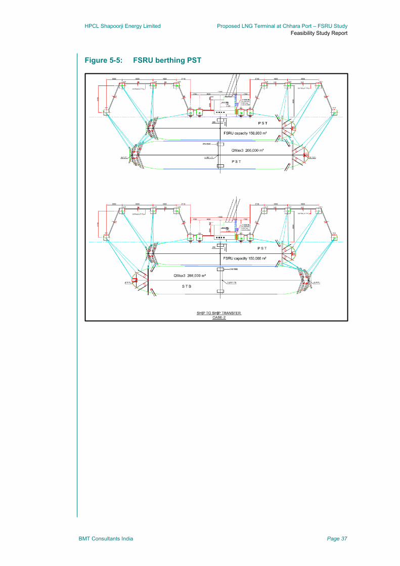
HPCL Shapoorji Energy Limited Proposed LNG Terminal at Chhara Port – FSRU Study
Feasibility Study Report
BMT Consultants India Page 37
Figure 5-5: FSRU berthing PST
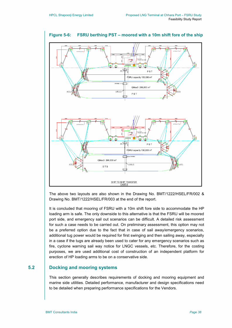
HPCL Shapoorji Energy Limited Proposed LNG Terminal at Chhara Port – FSRU Study
Feasibility Study Report
BMT Consultants India Page 38
Figure 5-6: FSRU berthing PST – moored with a 10m shift fore of the ship
The above two layouts are also shown in the Drawing No. BMT/1222/HSEL/FR/002 &
Drawing No. BMT/1222/HSEL/FR/003 at the end of the report.
It is concluded that mooring of FSRU with a 10m shift fore side to accommodate the HP
loading arm is safe. The only downside to this alternative is that the FSRU will be moored
port side, and emergency sail out scenarios can be difficult. A detailed risk assessment
for such a case needs to be carried out. On preliminary assessment, this option may not
be a preferred option due to the fact that in case of sail away/emergency scenarios,
additional tug power would be required for first swinging and then sailing away, especially
in a case if the tugs are already been used to cater for any emergency scenarios such as
fire, cyclone warning sail way notice for LNGC vessels, etc. Therefore, for the costing
purposes, we are used additional cost of construction of an independent platform for
erection of HP loading arms to be on a conservative side.
Docking and mooring systems 5.2
This section generally describes requirements of docking and mooring equipment and
marine side utilities. Detailed performance, manufacturer and design specifications need
to be detailed when preparing performance specifications for the Vendors.
HPCL Shapoorji Energy Limited Proposed LNG Terminal at Chhara Port – FSRU Study
Feasibility Study Report
BMT Consultants India Page 39
Combining elements of both conventional jetty mooring and docking and offshore ship-to-
ship mooring systems, and with more than two entities required to interface with each
other, systems integration naturally becomes more complex and there is no “generic”
docking, mooring and fendering package that can be applied to FSRUs.
For option A, which is a more complex case than option B using conventional mooring
configurations, a comprehensive overview should be undertaken and the design
requirement of all stakeholders aligned and coordinated.
The Ship-to-Ship docking and mooring scope is a shipyard led activity, with a brief purely
focused on the conversion of the vessel or a new build specification. However, from
planning and design perspective the design of the jetty should be done keeping an
emphasis on integrating the overall docking and mooring systems.
The docking and mooring system for FSRUs consists of mechanical, instrumentation and
control and monitoring elements - all of which must function together to assure safe and
efficient operation across the three constituents: jetty, FSRU and LNGC. Compatibility at
each interface ensures improved operational control, data sharing and flexibility for the
FSRU.
Quick Release Mooring Hook (QRMH) system
Quick Release Mooring Hooks (QRMHs) are an essential part of the docking and mooring
system. QMRH system shall be designed to cast off the mooring lines of ships which are
moored to the dolphins and which, following completion of the unloading activities, wish to
put to sea and to ensure that these mooring lines can be safely cast off simultaneously.
Each hook shall be equipped with a manual release mechanism and the operations of the
hooks shall be completely spark-free.
All mooring units shall be equipped with:
Capstan motor assembly
Reversible motor starter
Foot switch to operate the capstan
Remote release control system
Mooring load monitoring system
QRMH will need to be mounted on the mooring and breasting dolphins of the jetty for
FSRU mooring in case of Option A and on both the jetties for mooring FSRU and LNGC
in case of option B.
In option A, additional QRMH will need to be installed on FSRU, specifically designed and
rated QRMHs will need to be installed on FSRU for LNGC mooring on to the FSRU. STS
operation requires the LNGC to be berthed with about 5-6 m separation from the FSRU,
so the design of the QRMHs must take into account the reduced mooring line length in
this STS configuration, as this affects shock absorption capabilities and the high transient
loads may damage mooring lines particularly due to chafing through chocks. In this
HPCL Shapoorji Energy Limited Proposed LNG Terminal at Chhara Port – FSRU Study
Feasibility Study Report
BMT Consultants India Page 40
respect, deflections of the lines mooring the LNGC to the FSRU should be kept to a bare
minimum. Layout of mooring hooks on the FSRU requires careful planning.
In STS mooring arrangement, the mooring lines may be provided by the transient LNGC
carrier which may result in lines of unknown condition and capacity. Consideration could
be given to using dedicated lines stored on board and provided by the FSRU.
Berthing Aid System (BAS) or Docking Aid System
The BAS monitors shall be installed to record the vessel approach and departure. It
measures the distance from the unloading platform to the vessel and calculates the
approach speed and angle. It shall be installed with a large LED display panel to display
this information for the pilot and the jetty dock master in several ways. It shall also be
equipped with audio-visual alarms, hand held pagers and small portable graphic displays.
For option A, BAS would need to be installed on the jetty as well as on the FSRU. In case
of option B, BAS system will need to be installed on both the jetties.
Mooring Load Monitoring System (MLMS)
The MLMS shall be provided to monitor mooring lines and warnings in case of dangerous
loads. It shall be based on digital control network. Load cells mounted in the quick release
hooks provide signals to the digital network via amplifiers mounted in the hook motor
starter. A flash light and horn will be energized when the load on the mooring hooks
exceeds the predestined value.
Ship to Shore Communications
Ship Shore Link shall be used as per SIGTTO Recommendations and Guidelines for
Linked Ship/Shore Emergency Shut-Down of Liquefied Gas Cargo Transfer in 1987.
Primarily for Emergency Shut-Down (ESD), the systems support telecommunications and
data transfer.
There are numerous considerations to take into account for the instrumentation, control
and monitoring systems and key requirements to be considered are:
The jetty
Jetty will require plant operations and process oversight, as well as load monitoring
data, Met-ocean data and berthing data. A jetty control room is therefore envisaged to
be constructed to house all the marine operations. Alternatively the jetty control room
may be unmanned with all jetty operations such as loading, ESD, Mooring Tension
and Emergency Release being transferred to the FSRU control room.
The FSRU
FSRU will require plant operations and process oversight, as well as load monitoring
data, Met-ocean data and berthing data. In many cases the FSRU may be used as
the primary control centre for the monitoring of mooring line tensions from the jetty
and those to the LNGC (in the case of Option A - STS mooring). The instigation of
emergency mooring release of jetty and/or LNGC mooring lines will also be required
from the primary control centre.

HPCL Shapoorji Energy Limited Proposed LNG Terminal at Chhara Port – FSRU Study
Feasibility Study Report
BMT Consultants India Page 41
The LNGC
The LNGC needs to monitor and maintain the mooring system during cargo
operations, so access to mooring line data is essential.
All of the above rely on a compatible SSL for Emergency Shutdown control, Emergency
Mooring Release and load monitoring data transfer, hot line communications and,
increasingly for FSRU operations, a common data link between the 3 platforms
Environmental Monitoring System (EMS)
The EMS shall be capable of measuring, indicating, transmitting & recording signals and
display in the control room. The sensors in the EMS shall be installed to monitor following
environmental parameters:
wind speed and direction,
sea current speed and direction,
air humidity,
wave height,
wave period,
tidal elevation.
Gangway access tower
A Gangway access tower with a telescopic gangway shall be provided on the unloading
platform. Gangway access towers are proprietary products and shall have additional
specs like the ability to cater to larger ship sizes, shall have a hydraulic crane, fire
monitor, control cabin and metal coverage for protection of its users against extreme
weather conditions.
One gangway tower would be needed for each option respectively.
5.2.1 Fendering requirement
Conventionally, LNGC berthing against a hard panel are designed to withstand accidental
berthing energy requirements of LNGC. Typically cone type fenders with front panels are
found adequate.
In case of option A, the FSRU will be moored over the long term and will normally be hard
up against fender panels due to the requirement to keep the mooring lines tensioned.
This subjects fenders, fender panels and associated chain and hardware to constant
stress. Also, berthing loads will significantly increase during STS berthing and also with
the LNGC alongside the FSRU. Other considerations such as two floating body
movements; fender response from the effect of passing vessels, etc. must be examined
in detail. Detailed mooring analysis is recommended for the same. Selection of the
correct fender is therefore not limited to Energy and Reaction performance requirements.
Other factors such as rubber composition, aging, UV exposure, temperature and
immersion must also be considered if longevity of the fender and its hardware is to be
guaranteed. Likewise, reducing abrasion between fender facing and ship’s hull and easy

HPCL Shapoorji Energy Limited Proposed LNG Terminal at Chhara Port – FSRU Study
Feasibility Study Report
BMT Consultants India Page 42
change out of damaged facing sections are also relevant considerations for FSRU
mooring.
The fender system must also be considered as part of the mooring system, and on the
FSRU, their associated deployment and retrieval systems. Here, the smaller footprint
that’s essential on the STS operations needs to be considered. Pneumatic fenders with
chain tire nets have been the traditional choice for Ship-to-Ship operations. The downside
of pneumatic fenders is that they cannot offer flotation redundancy, once punctured they
will sink and, if filled with water, may overload the fender deployment system if lifted.
However, foam fenders can be manufactured without chain tire nets and provide lower
frictional resistance since the fender skin can be of a low friction polyurethane material
rather than rubber. Virtually unsinkable they could be considered a heavy duty alternative
solution to pneumatic fenders and better suited for some FLNG projects.
Foam-filled fenders can offer similar reaction and energy performance to pneumatic
fenders and can be engineered to offer low hull pressure. Importantly, in the event of an
LNG spill, foam fenders have been shown to be much more resistant to damage from low
temperatures than pneumatic fenders.
Three types of fenders are therefore envisaged as follows:
FSRU – Jetty fenders. They will be required for both the options, however, design
rating will be different, and higher rated ones will be needed for option A.
Conventional cone type fenders for LNGC berthing against the jetty in case of
option B
Pneumatic or foam filled fenders for LNGC to FSRU STS berthing.
Navigational requirements 5.3
The water area - the plan, dimensions and the water depths in the entrance/approach
channel harbour/manoeuvring basin and at the berths should be sufficient to permit the
largest vessels in terms of length overall (LOA), beam and fully laden draught to be
serviced without causing the vessels to take undue risks.
This section assesses the options from marine navigation and safety perspective using
following parameters:
Wave tranquillity
Wind
Under Keel clearance
Manoeuvring safety
5.3.1 Wave tranquility
The wave conditions at the site can have a significant effect on ship manoeuvring and
mooring. These can be categorised as locally wind generated (wind) waves and longer
period (swell) wave conditions from more distant storms and weather systems.

HPCL Shapoorji Energy Limited Proposed LNG Terminal at Chhara Port – FSRU Study
Feasibility Study Report
BMT Consultants India Page 43
Waves can also originate from other sources, including pressure field effect (caused by
passing ships).
An LNG STS transfer operation is an operation of some complexity and no specific
guidelines are available due to lack of extensive industry experience of LNG. LPG and
petroleum industry experience is exhaustive, and recently STS operations of LNG
offshore have been on the rise, e.g. Excelerate recently announced their 500th STS
operation offshore. However, STS operations in a sheltered harbour against hard jetty
structures, though less complex than off-shore operations do not have many precedents
in the past, even though recently some of the terminals worldwide have adopted such
operations. Therefore, it is essential that the unique elements of the operations are
recognised and that a full and thorough risk assessment is performed.
The weather conditions under which LNG STS transfers can take place may impose
restrictions on the operations. Following Met-ocean conditions must therefore be carefully
evaluated for planning purposes and operations.
Visibility
Wind direction
Wind velocity
Wave height
Wave period and direction
Figure 5-7: Typical STS configuration
Tranquillity requirements
In option A, where STS operations are planned, environmental limits will differ from option
B where conventional mooring is planned.
Vessel motions are recognised as having the potential for damaging impacts from
sloshing within partly-filled LNG cargo tanks that have membrane containment systems.
Since, the LNG operation in our case is proposed to be in sheltered waters, it may be

HPCL Shapoorji Energy Limited Proposed LNG Terminal at Chhara Port – FSRU Study
Feasibility Study Report
BMT Consultants India Page 44
generally regarded that sloshing impacts will not pose a risk. A detailed assessment is
recommended to be undertaken in the advanced stages of the project execution to
investigate any potential of significant sloshing happening at the jetty specifically for
option A for STS operations and for option B, this may not be required.
Tranquillity requirement also depends on the use of cargo transfer equipment to be used
for STS operations. Cargo transfer can be done either with flexible hoses or hard arms.
The design of the cryogenic transfer system and the related motion capabilities are the
central boundary condition for the operational range of the entire STS operation.
FMC Technologies’ rigid Marine Loading Arms are currently state-of-the art. They have
been designed by FMC to handle relative motion amplitudes between the two vessels of
±1.0 m in longitudinal, ±2.0 m in transverse and ±1.2 m in vertical direction. Due to these
limitations, STS transfer with rigid loading arms is currently possible only for calm waters
to moderate sea states. A detailed dynamic mooring analysis needs to be carried out to
study the moored response of the two floating bodies under environmental loads to
compute predicted vessel movements under moored conditions. The allowable
movement is dependent on various parameters of wind and wave loading, and therefore
a particular number of a wave height, period, etc. cannot be concluded without the
detailed studies. However, based on the experience of past STS operations under
sheltered conditions, it is believed that wave heights less than 0.7m and relatively smaller
wave periods (~6s) would prove to be an upper limit of the wave conditions. This upper
limit should not be considered as absolute recommendations as other parameters like
wind speed, directions, currents, etc. play a very important role in vessel response.
Use of Flexible cryogenic hoses is now becoming poplar for STS operations, wherein its
upper limit for environmental parameters is considered to be much higher than the hard
arms.
Limits
During the offloading process, the mooring arrangement should ensure that the carrier
manifold stays within the operating envelope of the loading arm during LNG transfer.
The FSRU will be equipped with either standard loading arms or flexible hoses. The
loading arms will be similar to the type used in onshore terminals, but modified to account
for relative motions between LNGC and FSRU. The FSRU will also be fitted with
equipment for guiding the arms onto the carrier’s connection flanges. This pre-coupling
guide operation will be necessary to compensate for relative motion during coupling when
the relative motion exceeds +/- 0.5m.
Operational wave height limits (Hs) for safe unloading arm operations are provided below.
Option A: STS operations, Hs < 0.7m using hard arms. Operating limits for use of
cryogenic hoses must be studied in details, but are expected to be in the range of Hs
= 0.7 to 1.5m.
Option B: Conventional operations. Hs < 1.5m
It must be noted that the above figures are indicative only and should be used with
caution for planning purposes only. Detailing modelling and mooring analysis
HPCL Shapoorji Energy Limited Proposed LNG Terminal at Chhara Port – FSRU Study
Feasibility Study Report
BMT Consultants India Page 45
should be carried out and limits w.r.t. relative motions of the vessels must be
known and cargo transfer system then designed accordingly.
5.3.2 Wind
The wind conditions at the site can have a significant effect on ship manoeuvring and ship
mooring. The effect of the wind on a ship depends on the wind speed and relative
direction, as well as the overall windage of the ship. In general, the maximum wind forces
that act on a ship are associated with beam winds.
LNG carriers with a spherical containment system (Moss-Rosenberg) have
proportionately higher windage than those with a prismatic/membrane containment
system and vessels in ballast have relatively more windage than laden vessels because
of the increase in freeboard. Consequently, while all ships will be affected by the wind
conditions, LNGCs with spherical tanks and vessels in ballast will be more sensitive to the
wind than laden vessels or those with membrane tanks.
Local conditions
The local wind in the region is mainly affected by the strong winds coming from south-
west and relatively weak winds coming from North-east. In general the wind climate of
the region is divided into four seasons as Pre-monsoon (March-May), SW-monsoon
(June-September), Post-monsoon (October - November) and NE-monsoon (December-
February).
From March to May the winds are mostly westerly. This period together with post-
monsoon season) is also considered as the cyclone season. There are some records
depicting wind speeds of 22-28 knots, coming also from the direction sector 105-195°N in
these months. During SW monsoon the prevailing wind direction is south-westerly, with
wind speeds regularly between 15 and 30 knots. There are a few outliers in direction
sector 105-165°N with the exceedance in wind speed of about 20 knots. These events
are probably associated with the tail-end of the cyclone season, with some cyclone
events persisting into June. Post monsoon season is a transition period and the winds
come from all directions with predominant wind direction from North. The maximum
prevailing winds come from the NE quadrant 10 to 20 knots
Offshore annual average wind climate based on (UK) Met office predictions are shown in
below Figure 5-8.The wind table for an offshore point located at 20.28° N, 70.42°E covers
the period from May 1999-November 2008 based on UKMO Global Wave Model. The
total number of hours recorded are 84048. The local region is mainly affected by the
strong winds coming from S-W and relatively weak winds coming from N-E. During south-
west monsoon i.e. June-September highest wind speeds between 15 to 30 knots from
south-west directions are recorded. While westerly wind speeds up to 25 knots occur
during the cyclone season i.e. March-May.

HPCL Shapoorji Energy Limited Proposed LNG Terminal at Chhara Port – FSRU Study
Feasibility Study Report
BMT Consultants India Page 46
Figure 5-8: Wind scatter table
Limits
The following limits may be considered as providing a guide for safe operations.
However, detailed site and vessel-specific navigation simulations, mooring analysis, risk
assessments and met ocean data analysis is recommended to be carried out in the detail
design stage:
Mooring equipment to be designed for 60 knots wind from any direction as per
OCIMF recommendations, simultaneously with either:
3 knots current at 00 or 1800
2 knots current at 100 or 1700
0.75 knots current from the direction of maximum beam current loading
Approximately 10 m/sec or 20 knots is the recommended safe wind limit for berthing
vessels with a projected wind area greater than 5000 m2. LNGC/FSRU of sizes
150,000m3 would typically have windage area greater than 5000 m2
Approximately 15 m/sec or 30 knots is the recommended safe wind limit for cargo
transfer operations.
Approximately 20 m/s or 40 knots is the recommended safe wind limit for
disconnection of loading arms subject to confirmation from the manufacturers.
Approximately 22 m/sec or 45 knots is the recommended safe mooring wind limit
These operational guidelines are applicable for sheltered berths (significant wave height
less than 0.6 m). Decreased limiting criteria may be applicable for increased wave
heights.
Wind speed is defined as the 30 second average mean wind (gust) speed as measured
at a standard datum height of 10 m above the ground or water surface. Since the gust or
30 s average mean wind speed is not available at the moment, it is recommended to do a
detailed wind and persistence study to establish down time for berthing and loading
operations due to wind.
HPCL Shapoorji Energy Limited Proposed LNG Terminal at Chhara Port – FSRU Study
Feasibility Study Report
BMT Consultants India Page 47
It is also recommended to undertake an operational-based and design-based
mooring evaluation. The design based mooring evaluation uses all combinations of
vessel mooring equipment that will produce the highest load in the mooring
structures and breasting dolphins, whereas the operational-based evaluation will
use the combination of vessel mooring equipment which results in the highest
stress in the mooring lines and largest vessel movements.
5.3.3 Under Keel clearance
Dredged depth inside the port area is around -15.0 m CD. The water depth in the
approach channel and the harbour basin, and in front of and alongside the berth should
be sufficient for safe manoeuvring. The selected water depth is usually based on the
following factors:
draught of the loaded design ship
tidal variations
ship movements under wave action
trim variations due to cargo operations
squat (reduction in under keel clearance due to the suction effect induced by higher current velocity between sea bottom and the ship)
character of bottom – a higher UKC will be needed for a rock bottom
variations in actual dredged depths from the theoretical
Allowance for sedimentation between two maintenance dredging programs.
An under keel clearance to account for squat, trim, rolling and pitching, current, velocity,
inaccuracies in hydrographic survey, salinity, etc. is considered over and above the fully
laden draught of design vessels in the planning for safe servicing of the vessels alongside
the berth, Common Manoeuvring Area/Turning Circle and in the Access Channel. The
UKC does not include allowances for sedimentation between two maintenance dredging
programs.
A considerable amount of work had been carried out on this aspect by the PIANC,
ICORELS Committee No. IV (Permanent International Association for Navigational
Congresses - International Commission for Reception of Large Vessels). After a detailed
study, the commission made the following general recommendations on UKC:
Open sea area (in outer approach channel) : for those exposed to strong and long stern or quarter swell, where speed may be high, gross UKC should be about 20% of the maximum draught of ships.
Channel: for sections exposed to strong and long swell, gross UKC should be about 15% of the draught.
Channel: less exposed to swell, gross UKC should be about 10% of the draught.
Manoeuvring and berthing areas for those exposed to swell (without full protection of breakwater): gross UKC should be about 10 to 15% of the draught.
Manoeuvring and berthing areas protected (full protection by breakwater): gross UKC to be about 7% of the draught.
A total UKC - to account for squat, trim, rolling and pitching, current velocity, inaccuracies in hydrographic survey, salinity etc. - of 10% of the fully laden draught

HPCL Shapoorji Energy Limited Proposed LNG Terminal at Chhara Port – FSRU Study
Feasibility Study Report
BMT Consultants India Page 48
of the vessel at the berths, in the berth approach areas and in the turning circle and manoeuvring areas; and 20% in the approach channel will need to be provided.
Ship owners and charterers require minimum clearance of 10% of the draught at berth
and clearance of 10% plus squat for safe navigation during manoeuvring
The draft of the channel should account for potential allowances in UKC policies of ship
owners and charterers require minimum clearance of 10% of the draught at berth and
clearance of 10% plus squat for safe navigation during manoeuvring as mentioned above.
Detailed calculations were carried out to investigate adequacy of the existing depths
based on estimation of squat, estimation of increase in draught requirement due to heel /
list, allowance for safety in manoeuvring, dredging tolerance etc., Gross UKC thus
calculated is as below:
Table 5-1: Calculation of gross depth requirements
Location Static
draught
(m)
Allowance
for squat
(m)
Allowance
for heel/list
(m)
Allowance for
safety in
manoeuvring
(m)
Additional
10% margin
of static
draught (m)
Gross
Depth
(m)
Berth 12.5 0.09 0.46 0.8 1.25 15.10
Turning circle 12.5 0.09 0.46 0.8 1.25 15.10
Channel inside breakwater 12.5 0.35 0.46 0.8 1.25 15.36
Channel at entrance 12.5 0.35 0.46 1.4 1.25 15.96
Channel outside 12.5 0.35 0.46 2.6 1.25 17.16
Considering that Mean Lowest Low Water (MLLW) = +0.64 m CD and assuming ship
manoeuvres are restricted to MLLW and at berth LLLW of 0.0 m
Therefore following dredge depths are estimated:
Berth area inside breakwater = 15.10m. Therefore 15 m depth is considered
adequate.
Turning basins and approach channel inside breakwaters – 15.96 m. Therefore 15 m
depth is considered adequate.
The PIANC WG 49 report provides guidance for the conceptual design of UKC
requirements, as follows.
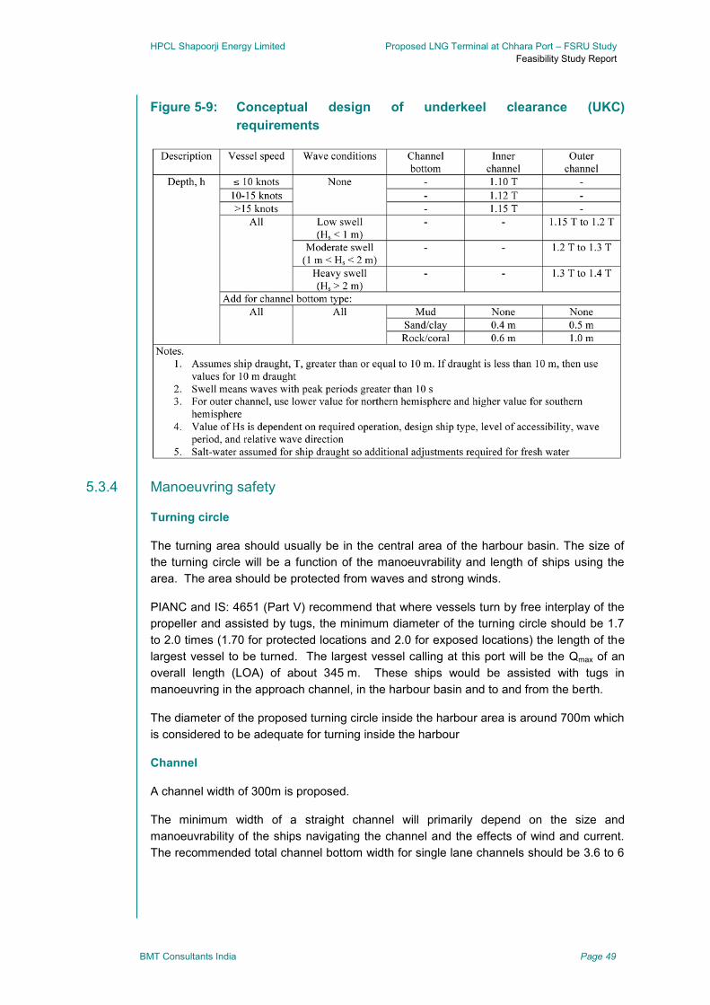
HPCL Shapoorji Energy Limited Proposed LNG Terminal at Chhara Port – FSRU Study
Feasibility Study Report
BMT Consultants India Page 49
Figure 5-9: Conceptual design of underkeel clearance (UKC)
requirements
5.3.4 Manoeuvring safety
Turning circle
The turning area should usually be in the central area of the harbour basin. The size of
the turning circle will be a function of the manoeuvrability and length of ships using the
area. The area should be protected from waves and strong winds.
PIANC and IS: 4651 (Part V) recommend that where vessels turn by free interplay of the
propeller and assisted by tugs, the minimum diameter of the turning circle should be 1.7
to 2.0 times (1.70 for protected locations and 2.0 for exposed locations) the length of the
largest vessel to be turned. The largest vessel calling at this port will be the Qmax of an
overall length (LOA) of about 345 m. These ships would be assisted with tugs in
manoeuvring in the approach channel, in the harbour basin and to and from the berth.
The diameter of the proposed turning circle inside the harbour area is around 700m which
is considered to be adequate for turning inside the harbour
Channel
A channel width of 300m is proposed.
The minimum width of a straight channel will primarily depend on the size and
manoeuvrability of the ships navigating the channel and the effects of wind and current.
The recommended total channel bottom width for single lane channels should be 3.6 to 6

HPCL Shapoorji Energy Limited Proposed LNG Terminal at Chhara Port – FSRU Study
Feasibility Study Report
BMT Consultants India Page 50
times the beam of the design ship depending on the sea and wind conditions. The width
of a restricted channel should be measured at the bottom of the dredged depth.
Width of approach channel and alignment was found to be adequate.
Ease in manoeuvring
Detailed ship handling and manoeuvring simulations shall be carried out to confirm the
manoeuvring requirements such as;
Ability of vessels to arrive & depart from proposed berths in a safe, timely & efficient
manner under the combined effects of current, wind, tide & swell.
Ability of vessels to manoeuvre in the approach channel/turning circle in a safe, timely
& efficient manner under the combined effects of current, wind, tide & swell.
Confirm the suitability of the proposed size, location & orientation of the approach
channel/turning circle for safe & efficient transit of the vessel under the effects of
current, wind, tide & swell
Preliminary confirmation on the size & number of tugs to safely & efficiently
escort/assist the vessels during transit, turning, berthing/un-berthing including the
ability to assist the vessel during emergency conditions
Level of ease in manoeuvring, berthing and un-berthing.
Summary 5.4
Marine navigation and mooring systems have been reviewed and assessed in the
preceding sections. In summary, from overall perspective both the options are considered
technically feasible.
For option A, the only major show stopper for feasibility would be the tranquility conditions
at the berth for STS operations. Indicative limits for STS operations have been provided.
HPCL Shapoorji Energy Limited Proposed LNG Terminal at Chhara Port – FSRU Study
Feasibility Study Report
BMT Consultants India Page 51
6 Early commissioning timelines and cost
assessment
This section describes a broad time line involved in early commissioning using FSRU
option and block costs for the two options.
Project time line 6.1
The project timeline has been worked out based upon industry benchmarked estimates
for each activity. However, site specific constraints may be considered as additional for
evaluating the project completion timing. In general the timeline are estimated to be 23
months and 27 months for the two options Option-A and Option-B respectively. A
tentative programme (schedule) is attached. The programme does not take into account
the effect of monsoons as the actual start of construction is governed by the date of
tender. As such BMT recommend that the Contractor is advised to amend the programme
accordingly in order to achieve the time line. The basis for the programme is as stated
below:
6.1.1 Marine facilities
It has been assumed that the construction work under this scope shall progress from two
fronts, one for the approach trestle construction which would be a land based start, and
the other for the jetty head construction which would be a marine based start. Fabrication
and erection of a land based piling gantry and a jack up platform will trigger the start of
piling activities under the respective section of work.
For the approach trestle, the superstructure works pile cap & deck slab that follow the
piling activity will have to be taken up when sufficient pile bents have been completed and
this will follow the piling gantry till the completion of approach road. Subsequently the
steel fit outs and other miscellaneous installations will be commenced and completed.
For the jetty head, the construction of pile cap and deck slab will have to be taken up
once the piling activity is completed and the jack up may be moved to the next location
once the steel fit outs and other miscellaneous starts.
Marine activities fall on the critical path. Most other activities are subject to construction of
these. Therefore, considered together, Marine activities are estimated to have a timeline
of 18 months and 22 months for Option-A and Option-B respectively.
6.1.2 Topside facilities
The topside works includes installation of equipment on the approach trestle and jetty
head, as well as tie-ins onshore.
Topside work on approach trestle can commence in a step-wise fashion once each
section of the trestle is constructed and safety provisions (e.g., hand rails) are installed.
The topside contractor will first install plinth foundations and pipe supports and then will
HPCL Shapoorji Energy Limited Proposed LNG Terminal at Chhara Port – FSRU Study
Feasibility Study Report
BMT Consultants India Page 52
lay out pipe for installation of the large diameter unloading lines. This will be followed by
installation of pipe rack and cable tray support sections, and then placement of utility
piping on the racks. Coordination will be needed with the marine contractor to avoid
interference with movement of materials and personnel. When the approach trestle is
completed the topside contractor will finish all piping connections, install cable trays and
lay cable.
Similarly, work on the Jetty Head can be accomplished as the marine contractor finishes
work in local areas; for instance, when the marine contractor finishes the platform deck he
may move to the dolphins, freeing up the platform area for the topside contractor to begin
its installation work. When all topside facilities are installed, the topside contractor will
perform final connections for piping and cabling, and perform all needed testing.
Topside activities have two starting constraints, the equipment delivery lead-time and the
availability and suitability of location, i.e. trestle, jetty, foundation, etc. Considering all the
process activities together, we estimate a timeline of 18 months and 20 months for
Option-A and Option-B respectively.
6.1.3 FSRU timeline
In particular, the FSRU availability timeline of 15 months is a broad conservative estimate
and may vary from as low as 6 months to as high as 24 months, depending on the current
spare availability and commitment status of different suppliers.
6.1.4 Statutory clearances
As per client advice, we have not considered environment and other statutory clearances
in this schedule. However these will be required for starting the construction work at site
and could lead to un-due project delays if not available. As the site construction work
cannot start before Environment clearance, it should be available within 6-9 months of the
start date. During this time DPR/FEED can be undertaken.
Other statutory clearances for the project are assumed to be available.
6.1.5 Breakwater
As per specific client advice, we have not considered the breakwater in the project
schedule, and it is considered built when required. However, given the overall time
schedule of the FSRU terminal, breakwater should be available within 20 months and 24
months of the start date for Option-A and Option-B respectively.
6.1.6 DPR / FEED
The FSRU project DPR / FEED is the first major activity for the project. The design
specifications developed here will be as the basis in all procurement tenders. We
estimate time requirement of 6 months for this activity. However, DPR / FEED is assumed
to be available for the timeline estimation purpose.
HPCL Shapoorji Energy Limited Proposed LNG Terminal at Chhara Port – FSRU Study
Feasibility Study Report
BMT Consultants India Page 53
6.1.7 Critical path
Option-A
The FSRU procurement and delivery is the critical path activity in Option-A. As mentioned
above, this is subject to market dynamics and may not eventually cause a time constraint.
Given the time estimates in the project schedule, it is observed that non-critical Marine &
Process activities have a slack of 3 months and 1 month respectively.
If the FSRU is available earlier and not on the critical path, then long lead items such as
high pressure NG arm and cryogenic LNG arms, along with jetty construction are found to
be on the critical paths.
Option-B
Since two jetties have to be constructed in this option, the Marine construction activities
fall on the critical path. This leads to LNG circuit commissioning activities also to fall on
the critical path.
FSRU delivery is therefore a non-critical activity and has 3 months of estimated slack.
Schedule snapshots have been provided in the report. However, owing to large size, a
separate schedule PDF is also provided for clarity and legibility.
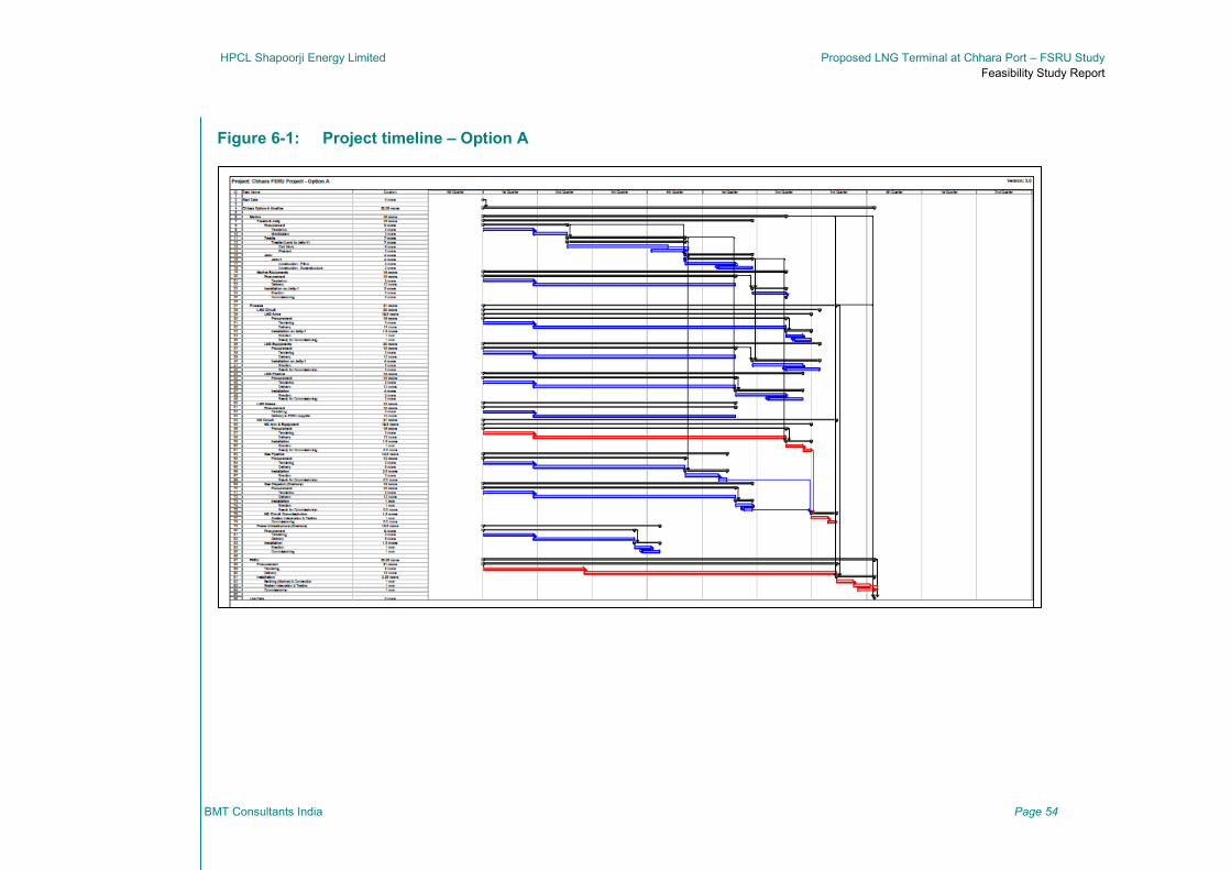
HPCL Shapoorji Energy Limited Proposed LNG Terminal at Chhara Port – FSRU Study
Feasibility Study Report
BMT Consultants India Page 54
Figure 6-1: Project timeline – Option A

HPCL Shapoorji Energy Limited Proposed LNG Terminal at Chhara Port – FSRU Study
Feasibility Study Report
BMT Consultants India Page 55
Figure 6-2: Project timeline – Option B
HPCL Shapoorji Energy Limited Proposed LNG Terminal at Chhara Port – FSRU Study
Feasibility Study Report
BMT Consultants India Page 56
Budget cost estimates 6.2
6.2.1 CAPEX & OPEX
Given the scope of this study, the cost estimates are based on secondary sources and
therefore may be considered as budgetary costs estimates with a tolerance of +/- 20%.
It must be noted that,
Estimates especially for the topsides equipment, mechanical process equipment,
utility and fire water piping, electrical equipment, instrumentation associated with the
process and utility equipment includes our estimate of material costs, shipping and
installation.
These estimates do not include any factor for inflation, construction management
burden, etc. Relevant factors may be introduced into these costs for Indian conditions
in the detailed cost estimates, but we do not foresee a significant impact on the
overall cost of the scheme and also these not being variables for the selection of an
option.
Taxes & duties are considered at the below aggregate rates
o EPC work-order rate – 4% of order value
o T&D on domestic equipment – 12% of equipment value
o T&D on imported equipment – 35% of equipment value
However, it must be noted that the market is very buoyant at present with most
contractors having empty order books. Further the prices of principal materials like steel,
cement have shown significant changes over past few years. The cost estimate therefore
must be therefore adopted with caution bearing in mind the above uncertainties.
Cost estimates for both the options are as tabulated below,
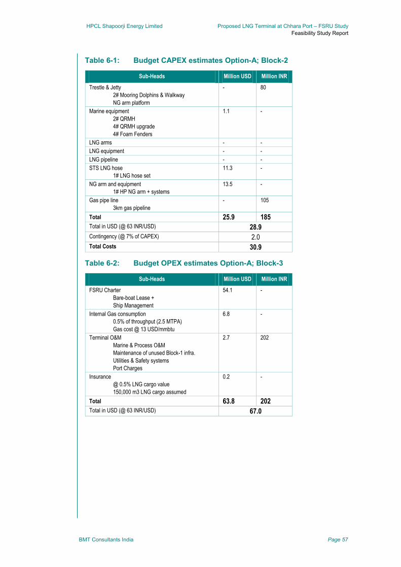
HPCL Shapoorji Energy Limited Proposed LNG Terminal at Chhara Port – FSRU Study
Feasibility Study Report
BMT Consultants India Page 57
Table 6-1: Budget CAPEX estimates Option-A; Block-2
Sub-Heads Million USD Million INR
Trestle & Jetty
2# Mooring Dolphins & Walkway
NG arm platform
- 80
Marine equipment
2# QRMH
4# QRMH upgrade
4# Foam Fenders
1.1 -
LNG arms - -
LNG equipment - -
LNG pipeline - -
STS LNG hose
1# LNG hose set
11.3 -
NG arm and equipment
1# HP NG arm + systems
13.5 -
Gas pipe line
3km gas pipeline
- 105
Total 25.9 185
Total in USD (@ 63 INR/USD) 28.9
Contingency (@ 7% of CAPEX) 2.0
Total Costs 30.9
Table 6-2: Budget OPEX estimates Option-A; Block-3
Sub-Heads Million USD Million INR
FSRU Charter
Bare-boat Lease +
Ship Management
54.1 -
Internal Gas consumption
0.5% of throughput (2.5 MTPA)
Gas cost @ 13 USD/mmbtu
6.8 -
Terminal O&M
Marine & Process O&M
Maintenance of unused Block-1 infra.
Utilities & Safety systems
Port Charges
2.7 202
Insurance
@ 0.5% LNG cargo value
150,000 m3 LNG cargo assumed
0.2 -
Total 63.8 202
Total in USD (@ 63 INR/USD) 67.0
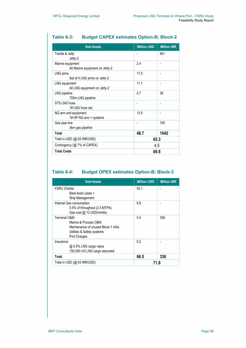
HPCL Shapoorji Energy Limited Proposed LNG Terminal at Chhara Port – FSRU Study
Feasibility Study Report
BMT Consultants India Page 58
Table 6-3: Budget CAPEX estimates Option-B; Block-2
Sub-Heads Million USD Million INR
Trestle & Jetty
Jetty-2
- 901
Marine equipment
All Marine equipment on Jetty-2
2.4 -
LNG arms
Set of 4 LNG arms on Jetty-2
17.0 -
LNG equipment
All LNG equipment on Jetty-2
11.1 -
LNG pipeline
700m LNG pipeline
4.7 36
STS LNG hose
1# LNG hose set
- -
NG arm and equipment
1# HP NG arm + systems
13.5 -
Gas pipe line
3km gas pipeline
- 105
Total 48.7 1042
Total in USD (@ 63 INR/USD) 65.3
Contingency (@ 7% of CAPEX) 4.5
Total Costs 69.8
Table 6-4: Budget OPEX estimates Option-B; Block-3
Sub-Heads Million USD Million INR
FSRU Charter
Bare-boat Lease +
Ship Management
54.1 -
Internal Gas consumption
0.5% of throughput (2.5 MTPA)
Gas cost @ 13 USD/mmbtu
6.8 -
Terminal O&M
Marine & Process O&M
Maintenance of unused Block-1 infra.
Utilities & Safety systems
Port Charges
5.4 336
Insurance
@ 0.5% LNG cargo value
150,000 m3 LNG cargo assumed
0.2 -
Total 66.5 336
Total in USD (@ 63 INR/USD) 71.8
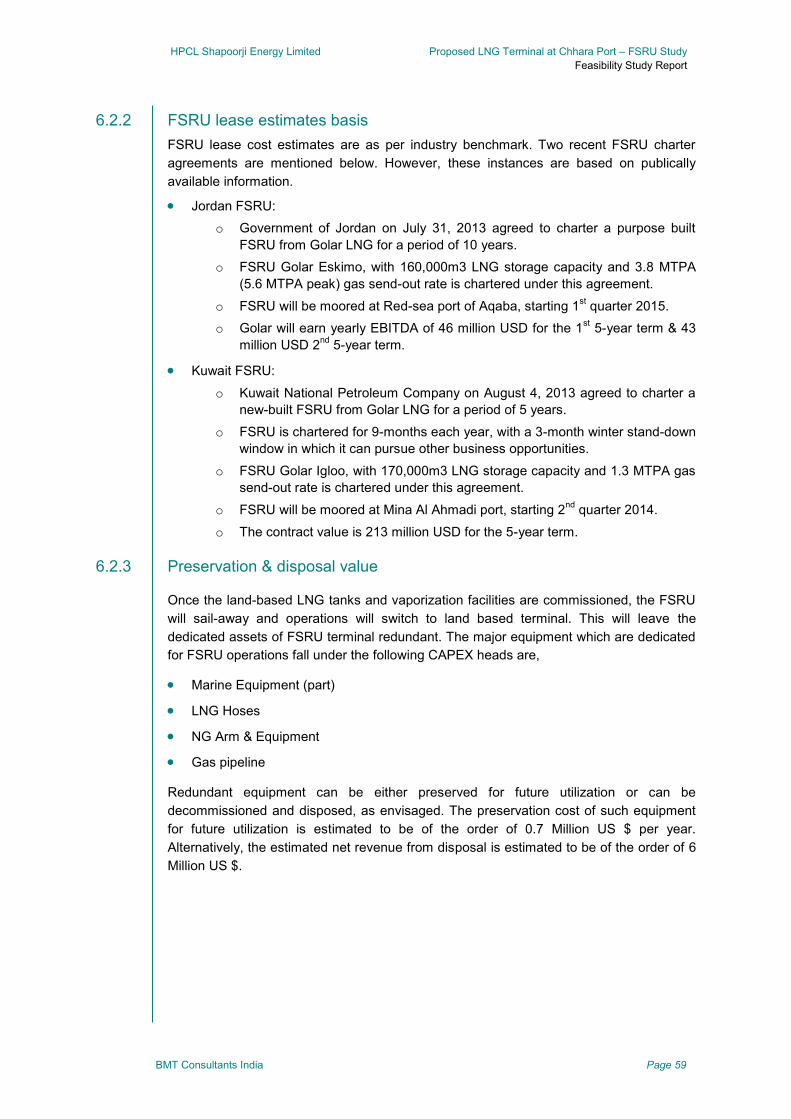
HPCL Shapoorji Energy Limited Proposed LNG Terminal at Chhara Port – FSRU Study
Feasibility Study Report
BMT Consultants India Page 59
6.2.2 FSRU lease estimates basis
FSRU lease cost estimates are as per industry benchmark. Two recent FSRU charter
agreements are mentioned below. However, these instances are based on publically
available information.
Jordan FSRU:
o Government of Jordan on July 31, 2013 agreed to charter a purpose built
FSRU from Golar LNG for a period of 10 years.
o FSRU Golar Eskimo, with 160,000m3 LNG storage capacity and 3.8 MTPA
(5.6 MTPA peak) gas send-out rate is chartered under this agreement.
o FSRU will be moored at Red-sea port of Aqaba, starting 1st quarter 2015.
o Golar will earn yearly EBITDA of 46 million USD for the 1st 5-year term & 43
million USD 2nd
5-year term.
Kuwait FSRU:
o Kuwait National Petroleum Company on August 4, 2013 agreed to charter a
new-built FSRU from Golar LNG for a period of 5 years.
o FSRU is chartered for 9-months each year, with a 3-month winter stand-down
window in which it can pursue other business opportunities.
o FSRU Golar Igloo, with 170,000m3 LNG storage capacity and 1.3 MTPA gas
send-out rate is chartered under this agreement.
o FSRU will be moored at Mina Al Ahmadi port, starting 2nd
quarter 2014.
o The contract value is 213 million USD for the 5-year term.
6.2.3 Preservation & disposal value
Once the land-based LNG tanks and vaporization facilities are commissioned, the FSRU
will sail-away and operations will switch to land based terminal. This will leave the
dedicated assets of FSRU terminal redundant. The major equipment which are dedicated
for FSRU operations fall under the following CAPEX heads are,
Marine Equipment (part)
LNG Hoses
NG Arm & Equipment
Gas pipeline
Redundant equipment can be either preserved for future utilization or can be
decommissioned and disposed, as envisaged. The preservation cost of such equipment
for future utilization is estimated to be of the order of 0.7 Million US $ per year.
Alternatively, the estimated net revenue from disposal is estimated to be of the order of 6
Million US $.
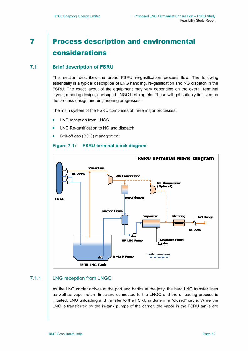
HPCL Shapoorji Energy Limited Proposed LNG Terminal at Chhara Port – FSRU Study
Feasibility Study Report
BMT Consultants India Page 60
7 Process description and environmental
considerations
Brief description of FSRU 7.1
This section describes the broad FSRU re-gasification process flow. The following
essentially is a typical description of LNG handling, re-gasification and NG dispatch in the
FSRU. The exact layout of the equipment may vary depending on the overall terminal
layout, mooring design, envisaged LNGC berthing etc. These will get suitably finalized as
the process design and engineering progresses.
The main system of the FSRU comprises of three major processes:
LNG reception from LNGC
LNG Re-gasification to NG and dispatch
Boil-off gas (BOG) management
Figure 7-1: FSRU terminal block diagram
7.1.1 LNG reception from LNGC
As the LNG carrier arrives at the port and berths at the jetty, the hard LNG transfer lines
as well as vapor return lines are connected to the LNGC and the unloading process is
initiated. LNG unloading and transfer to the FSRU is done in a “closed” circle. While the
LNG is transferred by the in-tank pumps of the carrier, the vapor in the FSRU tanks are
HPCL Shapoorji Energy Limited Proposed LNG Terminal at Chhara Port – FSRU Study
Feasibility Study Report
BMT Consultants India Page 61
transferred to the carrier tanks. The vapor return line balances the pressure across the
transferring tanks and avoids vapor locks or back pressure in the tanks. If the pressure in
the tanks cannot be maintained within acceptable limits, compressors are used, or
unloading rates must be reduced. The LNG receiving operations are to be so designed
that they are independent with respect to the continuous re-gasification operations of the
FSRU.
The LNG offloading pumps of the LNGC are typically rated such that they can offload
their LNG cargo within 15-18 hours from the time of connection, with a tug-boat-to-tug-
boat turnaround time estimate of 24 hours.
7.1.2 LNG Re-gasification to NG and dispatch
The re-gasification unit of the FSRU comprises of multiple re-gasification trains which
operate in parallel. Typically these trains are sized with inbuilt redundancy such that they
operate in configurations of 2-working-1-standby or N-working-1-standby mode. The re-
gasification trains comprise of LNG booster pumps and vaporizer systems. Given the
location and local conditions, only seawater based open-loop vaporizing system is
envisaged. Variable speed booster pumps may be considered to match the changes in
the gas dispatch requirements.
The in-tank LNG low-pressure pumps transfer the LNG from the tank to a common
suction drum. This suction drum is connected to multiple booster-pump–vaporizer re-
gasification trains. The booster pumps increase the liquid pressure up to the pressure
slightly higher than that required at the NG dispatch point. While the vaporizers gasify the
LNG into NG, which is thereafter metered and dispatched to the jetty via high pressure
NG unloading arms.
7.1.3 Boil-off gas (BOG) management
LNG stored in cryogenic state in the low pressure storage tanks of the FSRU. As the
surrounding heat leaks into the storage tank, proportionate amount of LNG boils off and
increases the pressure of the tank. If this pressure is not timely reduced, it could cause
un-due stress to the tank walls leading to fatigue and breach of containment. Under
steady state this boil-off gas is evacuated from the storage tank and the pressure is kept
within acceptable limits. The boil-off gas is at very low tank pressure, and therefore is first
compressed to workable pressure of about 8 barg by the boil-off compressor. Thereafter,
in an FSRU the compressed boil-off gas can be managed in one of the following
processes, 1) it could be either sent to on-board steam boiler or turbine to be fired and
produce steam or electricity respectively; or 2) it could re-liquefied in a re-condenser and
sent back into the LNG tanks for storage; or 3) optionally, it could be further compressed
and injected into the NG dispatch system.
7.1.4 Infrastructure requirements
The proposed project will involve land side and marine facilities. The land side facilities
primarily involve a corridor for pipelines for natural gas, access road and power.

HPCL Shapoorji Energy Limited Proposed LNG Terminal at Chhara Port – FSRU Study
Feasibility Study Report
BMT Consultants India Page 62
On the water side, the infrastructure proposed will consist of a harbour with breakwater,
construction of jetties and mooring dolphins, a service jetty for tugs and pilot vessels,
permanent berthing of a Floating Storage and Regasification Unit (FSRU), dredging,
pipelines for seawater intake and outfall and access road on a trestle up to the LNG jetty.
Navigational aids, pilotage, movement, etc. will be required as part of this project during
operations.
In addition, seawater based LNG re-gasification process using an open loop system using
the heat of the seawater as an unfired heat source for vaporizing LNG will be required.
Seawater temperature across the year will remain well above the required re-gasified
LNG temperature and thus SP is likely to consider seawater as heat source for vaporizing
LNG. The intake well with sea pumps may be located within the harbour basin to provide
lower sediment laden water. The quantity of seawater required is about 125,000 KLD at
ΔT of 5°C. Seawater taken from sea typically is expected to have a temperature range
from 20°C to 30°C. The seawater intake system will consist of various filters to remove
debris and hypo chlorination plant to reduce the corrosive effect of water on vaporizer and
to prevent bio fouling. The discharge free chlorine concentration will need to be below
1mg/L.
This seawater will be brought in contact with LNG with a shell and tube heat exchanger to
vaporize LNG flowing through closed tubes. Seawater will absorb cold energy from LNG
and vaporize LNG. Seawater temperature will drop to by 5° to 7°C and cold seawater will
be discharged in the sea. Regasified LNG will be fed in to gas grid at the battery limit of
FSRU at 5°C temperature and 90-100 bar pressure.
Environmental considerations 7.2
The environmental clearance process will primarily be driven by the requirements of the
Environmental Impact Assessment Notification 2006 and the Coastal Regulatory Zone
Notification 2011. Both these notifications are issued by the Ministry of Environment and
Forests under the Environmental Protection Act 1986.
As per the EIA notification, projects and activities are broadly categorized into two
categories - Category A and Category B, based on the spatial extent of potential impacts
on human health, natural and manmade resources. Category A projects are to be
accorded environmental clearance by the Central Government, while Category B projects
are under the State Government.
Ports and harbours with less than 5 Mtpa of cargo handling capacity and/or ports/
harbours with greater or equal to 10,000 tpa of fish handling capacity fall under Category
B projects. The project exceeds 5 MTPA and thus requires clearance from the Central
Government (MoEF). There is no specific mention of pipelines in the EIA notification,
except for pipelines passing through forest areas.
Since the project lies in the Coastal Zone, which for the sake of brevity in this report, can
broadly be described as areas on the coast within 500 m from the high tide line on the
landward side, the area between high tide line and low tide line and up to 12 nautical
miles for the offshore area. The reader is directed to the CRZ Notification in
www.envfor.nic.in for the complete text of the Notification. The CRZ Notification requires

HPCL Shapoorji Energy Limited Proposed LNG Terminal at Chhara Port – FSRU Study
Feasibility Study Report
BMT Consultants India Page 63
clearance for pipeline projects in the coastal zone from the Central Government after the
State Coastal Zone Management Authority recommends the project.
The CRZ notification specifies activities that are prohibited /permissible on a number of
criteria, the most important of which is the classification of the site in terms of CRZ-I, II or
III. CRZ-I areas are ecologically sensitive areas, where development activities are
generally prohibited, CRZ-II apply to areas in urban areas, while CRZ-III applies to
location in the coastal zone not falling under CRZ-I and II. The classification of the
coastal areas is based on the Coastal Zone Management Plan prepared by each State
and approved by MoEF.
The CRZ notification also requires a comprehensive EIA with three seasons for sites
considered to be undergoing Low to Medium shoreline erosion. The EIA conducted by
CES covers three seasons and thus fulfils this requirement.
The other clauses of the CRZ Notification that indicate that the project is not prohibited as
per the CRZ notification are:
1. The coastal regulation zone notification does not prohibit the transfer or handling of
ammonia as per clause 3(i)(a)
“Prohibited activities within CRZ,- The following are declared as prohibited activities within the
CRZ,-…..
(i) Setting up of new industries and expansion of existing industries except,-
(a) those directly related to waterfront or directly needing foreshore facilities; Explanation: The
expression “foreshore facilities” means those activities permissible under this notification and
they require waterfront for their operations such as ports and harbours, jetties, quays, wharves,
erosion control measures, breakwaters, pipelines, lighthouses, navigational safety facilities,
coastal police stations and the like.;
2. While transfer and handling is permitted through pipelines, the activities are controlled
as per Clause 4(i)(a) and 4(ii)d
4. Regulation of permissible activities in CRZ area.- The following activities shall be regulated except those
prohibited in para 3 above,-
(i)(a) clearance shall be given for any activity within the CRZ only if it requires waterfront and foreshore
facilities”
…..
“(ii) the following activities shall require clearance from MoEF, namely:- ….
(d) laying of pipelines, conveying systems, transmission line”
Thus, it can be concluded that the activity is a permissible activity requiring environmental
clearance from the Ministry of Environment and Forests (MoEF), Government of India.
The typical process leading to environmental clearance requires the following steps:
Terms of Reference Approval. Fresh TOR for LNG terminal including FSRU from
MoEF to be sought..
HPCL Shapoorji Energy Limited Proposed LNG Terminal at Chhara Port – FSRU Study
Feasibility Study Report
BMT Consultants India Page 64
Conduct EIA through a QCI approved agency. EIA report to be prepared for LNG
terminal shall include following aspects related to FSRU:
o Description of the FSRU focusing on the process flow rates, seawater
requirements for vaporizing LNG and safety measures included in the design.
The layout of the natural gas pipelines needs to be chosen such that future
expansion of the port does not interfere with operations of the LNG terminal.
o Prediction
Thermal dispersion modeling identifying the intake and outfall
location for discharge of coldwater
Impacts on marine ecology due to the disposal of cold water
Entrainment of marine life at the intake system
Release of free chlorine at the outfall
o Risk Analysis
Quantitative Risk Analysis - Consequence Analysis, frequency,
computation of risk, separation zones
Navigational safety
The Chemical Accidents (Emergency Planning, Preparedness, and
Response) Rules, 1996, Ministry Of Environment & Forests
Notification, (New Delhi, The 1st August, 1996)
Manufacture, Storage and Import of Hazardous Chemical Rules,
1989, Ministry of Environment and Forests, (Department Of
Environment, Forest And Wildlife) Notification, New Delhi, The 27th
November, 1989
o EMP/DMP
Include onsite and offsite plans, training, awareness and drills
Demarcate the HTL/LTL and CRZ through a MoEF approved agency.
Public hearing. A Public Hearing has been held for coal handling. Clarifications
may be required from MoEF on the need for conducting the public hearing again with
the revised activities
CRZ approval from State Government. EIA report for LNG terminal with FSRU will
need to be submitted
Environmental Clearance application to MoEF. An application for environmental
clearance will need to be made together with the EIA study report, HTL/LTL
demarcation, minutes of the Public hearing, CRZ approval and the Detailed Project
Report.
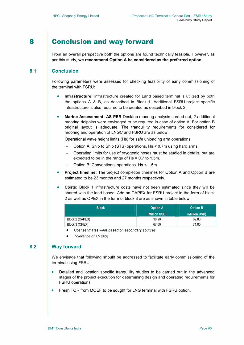
HPCL Shapoorji Energy Limited Proposed LNG Terminal at Chhara Port – FSRU Study
Feasibility Study Report
BMT Consultants India Page 65
8 Conclusion and way forward
From an overall perspective both the options are found technically feasible. However, as
per this study, we recommend Option A be considered as the preferred option.
Conclusion 8.1
Following parameters were assessed for checking feasibility of early commissioning of
the terminal with FSRU:
Infrastructure: infrastructure created for Land based terminal is utilized by both
the options A & B, as described in Block-1. Additional FSRU-project specific
infrastructure is also required to be created as described in block 2.
Marine Assessment: AS PER Desktop mooring analysis carried out, 2 additional
mooring dolphins were envisaged to be required in case of option A. For option B
original layout is adequate. The tranquillity requirements for considered for
mooring and operation of LNGC and FSRU are as below:
Operational wave height limits (Hs) for safe unloading arm operations:
Option A: Ship to Ship (STS) operations, Hs < 0.7m using hard arms.
Operating limits for use of cryogenic hoses must be studied in details, but are
expected to be in the range of Hs = 0.7 to 1.5m.
Option B: Conventional operations. Hs < 1.5m
Project timeline: The project completion timelines for Option A and Option B are
estimated to be 23 months and 27 months respectively.
Costs: Block 1 infrastructure costs have not been estimated since they will be
shared with the land based. Add on CAPEX for FSRU project in the form of block
2 as well as OPEX in the form of block 3 are as shown in table below:
Block Option A
(Million USD)
Option B
(Million USD)
Block 2 (CAPEX) 30.90 69.80
Block 3 (OPEX) 67.00 71.80
Cost estimates were based on secondary sources
Tolerance of +/- 20%
Way forward 8.2
We envisage that following should be addressed to facilitate early commissioning of the
terminal using FSRU:
Detailed and location specific tranquillity studies to be carried out in the advanced
stages of the project execution for determining design and operating requirements for
FSRU operations.
Fresh TOR from MOEF to be sought for LNG terminal with FSRU option.

HPCL Shapoorji Energy Limited Proposed LNG Terminal at Chhara Port – FSRU Study
Feasibility Study Report
BMT Consultants India Page 66
An application for environmental clearance will need to be made together with the EIA
study report, HTL/LTL demarcation, minutes of the Public hearing, CRZ approval and
the Detailed Project Report.
A separate risk assessment may be required to update the existing risk assessment
done as part of the DFR to include FSRU operations.
Undertake an operational-based and design-based mooring evaluation. The design
based mooring evaluation uses all combinations of vessel mooring equipment that
will produce the highest load in the mooring structures and breasting dolphins,
whereas the operational-based evaluation will use the combination of vessel mooring
equipment which results in the highest stress in the mooring lines and largest vessel
movements.

HPCL Shapoorji Energy Limited Proposed LNG Terminal at Chhara Port – FSRU Study
Feasibility Study Report
BMT Consultants India Page 67
9 Drawings

HPCL Shapoorji Energy Limited Proposed LNG Terminal at Chhara Port – FSRU Study
Feasibility Study Report
BMT Consultants India
Appendix A : Qualitiative Risk
Assessment

HPCL Shapoorji Energy Limited Proposed LNG Terminal at Chhara Port – FSRU Study
Feasibility Study Report
BMT Consultants India
Qualitative Risk Assessment
The properties of gas are well understood and its behaviour, when released to the
atmosphere, can be modelled within tolerances that allow for realistic contingency
planning and safety management.
Accidental release of LNG, (although rare) can create localised or greater scale hazard
situations. Risk exposures entailed in a LNG port project should therefore be analysed by
a Quantitative Risk Assessment (QRA) study. Such a study must involve the operations
at the terminal and the transit of vessels through the port. Risk assessments do not
themselves improve safety, but hey should be regarded as decision tools in order to
satisfy company safety policies and statutory requirements.
Risk Assessment for Chhara LNG terminal
Risk Assessment for the LNG terminal for Chhara has been carried out by the HSEL. Two
documents, viz. “Risk analysis, Disaster Management and Emergency Plan” and “Fire
hazard and safety systems” were critically reviewed. The studies covered:
Study of facility parameters - this involved collection of pertinent project information,
process engineering details such as flows, temperature, pressure, hydraulics and
other parameters.
Hazard Identification or HAZID - this included estimation of possible hazards through
a systematic approach covering identification of possible failure scenarios through
generic methods for estimating potential failures based on historical records based on
worldwide LNG accident data bases.
Consequence Effects Estimation - covering assessing the damage potential in terms
of heat radiation and establishing the vulnerable zone or distance/ area of interest for
fatalities or damage to important equipment/ structure etc.
Probability Estimation - covering estimation of event probabilities, ignition probabilities
and estimates on "how often" the events are likely to occur.
Risk Estimation - covering estimating risk levels for members of the general public
and risk reduction recommendations.
Emergency Response Plan - for the identified risks, an emergency management
structure is proposed for dealing with major emergencies during the operational
phase.
Safety philosophy
Risk assessment for the marine terminal and subsequent establishment of safety zones
was also carried out. The following safety distances and limiting conditions have been
recommended for safe and effective operations for a proposed LNG terminal at Chhara:

HPCL Shapoorji Energy Limited Proposed LNG Terminal at Chhara Port – FSRU Study
Feasibility Study Report
BMT Consultants India
Exclusion zone Boundary Limit
1000m gas dispersion zone
Emergency area around the Jetty head due to potential gas leak and dispersion with a risk of ignition up to LFL.
500m radius around manifold
Upper boundary limit- where space is not constraint and/or in the strong and prevailing wind directions. Hence we have allowed for a distance of 500m from the corner of the container berth, which is considered a main source for ignition.
400m restrictive access during unloading
Restriction area around the jetty head within 400m due to potential radiation in excess of 5 kW / m2 in case of major accident.
300m radius around manifold
Lower boundary limit- where space is constraint and/or any larger distance results in costly additional infrastructure like for example the extension of the breakwaters.
Hence in the two berth situation in Chhara, considering development of an LNG berth in future, it is recommended that the safety circle of 300m from the ship manifold during LNG transfer operations shall not be breached.
200m between LNG Cargo and any traffic
No traffic within 200m from any LNGC at berth or during approach / manoeuvring
600m manifold to manifold
For the other LNG vessel to be berthed alongside LNG vessel, a minimum of 130m clearance from exclusion zone to the vessels hull shall be provided. This includes 40m tug length + 40m length of line pull + 50m manoeuvring area. Together with the 300m radius as advised above, half a vessel length and 130m, this shall be 600m.
The study also concluded that to establish a more accurate value for the safety zone
radius quantitative risk analysis (QRA) shall be carried out before detailed design.
Risks during construction of LNG terminal
Two major items are perceived as major risks during construction of the LNG terminal:
Construction activities on the jetty and approach trestle during FSRU operations
The risk assessment done earlier concluded 1000m radius as emergency area
around the Jetty head due to potential gas leak and dispersion with a risk of ignition
up to LFL.
During FSRU operation on option A or option B,
due to the restrictive 1000m radius for source of
ignition, no hot works would be safe to be allowed
during cargo transfer and regasification operations
on the FSRU.
The adjacent figure illustrates the extent of the
restrictive zone
Construction on approach and jetty would comprise
installation of cryogenic pipeline, LNG unloading
arms, all utilities, safety equipment, deck furniture,
etc.
It is therefore recommended that no construction
works are planned on the jetty and approach trestle
during FSRU operations.
It is recommended that such construction works are completed along with jetty and
trestle construction.
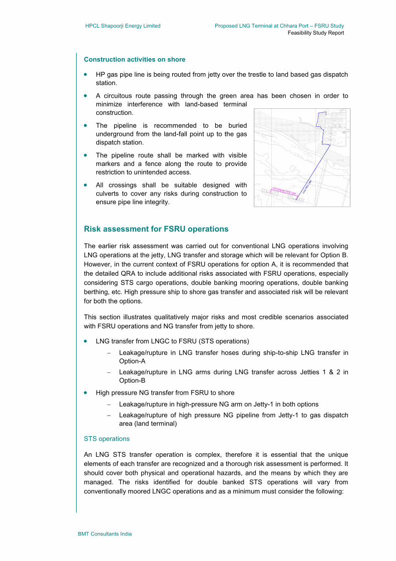
HPCL Shapoorji Energy Limited Proposed LNG Terminal at Chhara Port – FSRU Study
Feasibility Study Report
BMT Consultants India
Construction activities on shore
HP gas pipe line is being routed from jetty over the trestle to land based gas dispatch
station.
A circuitous route passing through the green area has been chosen in order to
minimize interference with land-based terminal
construction.
The pipeline is recommended to be buried
underground from the land-fall point up to the gas
dispatch station.
The pipeline route shall be marked with visible
markers and a fence along the route to provide
restriction to unintended access.
All crossings shall be suitable designed with
culverts to cover any risks during construction to
ensure pipe line integrity.
Risk assessment for FSRU operations
The earlier risk assessment was carried out for conventional LNG operations involving
LNG operations at the jetty, LNG transfer and storage which will be relevant for Option B.
However, in the current context of FSRU operations for option A, it is recommended that
the detailed QRA to include additional risks associated with FSRU operations, especially
considering STS cargo operations, double banking mooring operations, double banking
berthing, etc. High pressure ship to shore gas transfer and associated risk will be relevant
for both the options.
This section illustrates qualitatively major risks and most credible scenarios associated
with FSRU operations and NG transfer from jetty to shore.
LNG transfer from LNGC to FSRU (STS operations)
Leakage/rupture in LNG transfer hoses during ship-to-ship LNG transfer in
Option-A
Leakage/rupture in LNG arms during LNG transfer across Jetties 1 & 2 in
Option-B
High pressure NG transfer from FSRU to shore
Leakage/rupture in high-pressure NG arm on Jetty-1 in both options
Leakage/rupture of high pressure NG pipeline from Jetty-1 to gas dispatch
area (land terminal)
STS operations
An LNG STS transfer operation is complex, therefore it is essential that the unique
elements of each transfer are recognized and a thorough risk assessment is performed. It
should cover both physical and operational hazards, and the means by which they are
managed. The risks identified for double banked STS operations will vary from
conventionally moored LNGC operations and as a minimum must consider the following:
HPCL Shapoorji Energy Limited Proposed LNG Terminal at Chhara Port – FSRU Study
Feasibility Study Report
BMT Consultants India
Vessel compatibility
Location
Personnel
Equipment
Environment
Emergency planning
Examples of high risks associated with STS operations
Low energy collision: Inadequate control during berthing/unberthing operations may
lead to hull to hull contact/collision leading to physical damage on one or both ships.
Mooring operations; inadequate control during mooring, unmooring operations may
lead to personnel injury or fatality.
High energy collision: Inadequate navigational control by supply LNGC or third party
passing vessel may cause high energy collision with FSRU or LNGC during berthing,
unberthing or transfer operations resulting in significant damage, fatalities and loss of
containment
Loss of containment (LNG): Inadequate control, hardware failure, overflow or over
pressure during transfer operations may lead to an uncontrolled event resulting in a
full flow loss of containment and LNG release resulting in injury / steel damage
Loss of containment (LNG vapour) : Inadequate control during transfer operations
may lead to an uncontrollable loss of containment and vapour release leading to
ignition back to source resulting in fatalities / injury / hardware/steel damage
Loss of containment (LNG vapor in confined space): Inadequate control during
transfer operations may lead to an uncontrollable loss of containment and vapour
collection in a confined space leading to ignition with explosion causing fatalities /
injury / hardware/steel damage
Loss of containment (LNG to water): Inadequate control during transfer operations
may lead to an uncontrollable loss of containment and LNG release to water leading
to Rapid Phase transition resulting in hull plating of fender damage.
Personnel transfer: Failure or improper use of equipment used in personnel transfer
may lead to loss of control during transfer operations resulting in fatality or injury
Damage to cargo containment system: Cargo sloshing due to ship motions in the
prevailing swell conditions may result in damage to primary cargo containment
resulting in ship being unfit. Damage is only recognized during dry dock inspection
and may result in incremental cost of repair.
Guidelines
Industry guidelines are available for STS operations, and must be consulted while doing
the detailed risk assessment for STS operations. Some of the important ones specifically
for STS operations are:
OCIMF/SIGTTO ‘Ship to Ship Transfer Guide (Liquefied gas)
ICS/OCIMF ‘Ship to Ship Transfer Guide (Petroleum)

HPCL Shapoorji Energy Limited Proposed LNG Terminal at Chhara Port – FSRU Study
Feasibility Study Report
BMT Consultants India
OCIM ‘Mooring Equipment Guidelines’
EN 1474 – ‘Installation and Testing of Liquefied natural Gas – Design and testing of
Marine Transfer Systems.’
Tanker Safety Guide (ICS)
High pressure NG transfer from FSRU to shore
High pressure NG transfer from FSRU to shore will have an independent fast-response
Emergency Monitoring System (EMS) which will monitor the gas parameters such as
pressure, temperature, gas detectors at flange & joints, etc. The EMS also monitors the
arm’s movements in a 3-envelop scheme with halt, stop, disconnect philosophy. The
arm’s EMS will be integrated with the FSRU and Jetty EMS so as to ensure required
cascading of emergency alerts and responses. Appropriate fire-response systems will be
actuated in case any gas leakage is detected.
Leakage/rupture of high pressure NG pipeline from Jetty-1 to gas dispatch station
The risk of leakage of high pressure NG pipeline is minimal on the jetty and trestle as the
access to these areas is controlled. Additionally gas detectors, pressure & temperature
indicators at regular intervals will be connected to the pipeline monitoring system. In case
of any leak detection, gas flow will be stopped, and pipeline will be isolated. If required by
the level of emergency, pipeline line-pack will be diverted to a flare, located at a safe
distance.