Embed Size (px)
Citation preview

HP StorageWorksSAN Director installation guide
Part number: A7393-90009 Fourth edition: May 2007

Legal and notice information
© Copyright 2007 Hewlett-Packard Development Company, L.P.
© Copyright 2007 Brocade Communications Systems, Incorporated.
Hewlett-Packard Company makes no warranty of any kind with regard to this material, including, but not limited to, the implied warranties of merchantability and fitness for a particular purpose. Hewlett-Packard shall not be liable for errors contained herein or for incidental or consequential damages in connection with the furnishing, performance, or use of this material.
This document contains proprietary information, which is protected by copyright. No part of this document may be photocopied, reproduced, or translated into another language without the prior written consent of Hewlett-Packard. The information is provided “as is” without warranty of any kind and is subject to change without notice. The only warranties for HP products and services are set forth in the express warranty statements accompanying such products and services. Nothing herein should be construed as constituting an additional warranty. HP shall not be liable for technical or editorial errors or omissions contained herein.
Microsoft, Windows, Windows NT, and Windows XP are U.S. registered trademarks of Microsoft Corporation.
UNIX® is a registered trademark of The Open Group.
Printed in the US.
SAN Director installation guide

SAN Director installation guide 3
Contents
ContentsAbout this guide . . . . . . . . . . . . . . . . . . . . . . . . . . . . . . . . . . . . . . 13Intended audience . . . . . . . . . . . . . . . . . . . . . . . . . . . . . . . . . . . . . . . . . . . . . . . . . . . . . 13Related documentation . . . . . . . . . . . . . . . . . . . . . . . . . . . . . . . . . . . . . . . . . . . . . . . . . . 13Document conventions and symbols . . . . . . . . . . . . . . . . . . . . . . . . . . . . . . . . . . . . . . . . . 14HP technical support . . . . . . . . . . . . . . . . . . . . . . . . . . . . . . . . . . . . . . . . . . . . . . . . . . . . 15
HP-authorized reseller. . . . . . . . . . . . . . . . . . . . . . . . . . . . . . . . . . . . . . . . . . . . . . . . . 15Helpful web sites . . . . . . . . . . . . . . . . . . . . . . . . . . . . . . . . . . . . . . . . . . . . . . . . . . . . 15
1 Overview. . . . . . . . . . . . . . . . . . . . . . . . . . . . . . . . . . . . . . . . . 174/256 SAN Director features . . . . . . . . . . . . . . . . . . . . . . . . . . . . . . . . . . . . . . . . . . . . . 184/256 SAN Director models . . . . . . . . . . . . . . . . . . . . . . . . . . . . . . . . . . . . . . . . . . . . . . 19
Optional licenses . . . . . . . . . . . . . . . . . . . . . . . . . . . . . . . . . . . . . . . . . . . . . . . . . . . . 19Hardware components . . . . . . . . . . . . . . . . . . . . . . . . . . . . . . . . . . . . . . . . . . . . . . . . 19Intelligent port blades . . . . . . . . . . . . . . . . . . . . . . . . . . . . . . . . . . . . . . . . . . . . . . . . . 20
B-Series MP Router Blade (FR4-18i) . . . . . . . . . . . . . . . . . . . . . . . . . . . . . . . . . . . . . 20B-Series iSCSI Director Blade (FC4-16IP) . . . . . . . . . . . . . . . . . . . . . . . . . . . . . . . . . 21
4/256 SAN Director—port side . . . . . . . . . . . . . . . . . . . . . . . . . . . . . . . . . . . . . . . . . 234/256 SAN Director—nonport side. . . . . . . . . . . . . . . . . . . . . . . . . . . . . . . . . . . . . . . 25
High availability . . . . . . . . . . . . . . . . . . . . . . . . . . . . . . . . . . . . . . . . . . . . . . . . . . . . . . . 26Reliability . . . . . . . . . . . . . . . . . . . . . . . . . . . . . . . . . . . . . . . . . . . . . . . . . . . . . . . . . . . 27Serviceability . . . . . . . . . . . . . . . . . . . . . . . . . . . . . . . . . . . . . . . . . . . . . . . . . . . . . . . . . 27Software features . . . . . . . . . . . . . . . . . . . . . . . . . . . . . . . . . . . . . . . . . . . . . . . . . . . . . . 28
Security . . . . . . . . . . . . . . . . . . . . . . . . . . . . . . . . . . . . . . . . . . . . . . . . . . . . . . . . . . 28Network manageability . . . . . . . . . . . . . . . . . . . . . . . . . . . . . . . . . . . . . . . . . . . . . . . 28
Port numbering. . . . . . . . . . . . . . . . . . . . . . . . . . . . . . . . . . . . . . . . . . . . . . . . . . . . . . . . 29Optional hardware kits . . . . . . . . . . . . . . . . . . . . . . . . . . . . . . . . . . . . . . . . . . . . . . . . . . 31
2 Installing and configuring the 4/256 SAN Director . . . . . . . . . . . . 33Unpacking and verifying carton contents . . . . . . . . . . . . . . . . . . . . . . . . . . . . . . . . . . . . . . 34Installation overview . . . . . . . . . . . . . . . . . . . . . . . . . . . . . . . . . . . . . . . . . . . . . . . . . . . . 37
Selecting an operating location . . . . . . . . . . . . . . . . . . . . . . . . . . . . . . . . . . . . . . . . . . 37Cooling requirements . . . . . . . . . . . . . . . . . . . . . . . . . . . . . . . . . . . . . . . . . . . . . . . . . 37Power requirements . . . . . . . . . . . . . . . . . . . . . . . . . . . . . . . . . . . . . . . . . . . . . . . . . . 38
Setup tasks and estimated time required . . . . . . . . . . . . . . . . . . . . . . . . . . . . . . . . . . . . . . 38Installing the switch as a stand-alone unit . . . . . . . . . . . . . . . . . . . . . . . . . . . . . . . . . . . 40
Removing the chassis door . . . . . . . . . . . . . . . . . . . . . . . . . . . . . . . . . . . . . . . . . . . 40Installing the switch on a flat surface . . . . . . . . . . . . . . . . . . . . . . . . . . . . . . . . . . . . . . 41Installing the switch in a rack. . . . . . . . . . . . . . . . . . . . . . . . . . . . . . . . . . . . . . . . . . . . 42
Pre-installation checklist . . . . . . . . . . . . . . . . . . . . . . . . . . . . . . . . . . . . . . . . . . . . . 42

Contents4
Items required for installation . . . . . . . . . . . . . . . . . . . . . . . . . . . . . . . . . . . . . . . . . . 42Important rack mount safety guidelines . . . . . . . . . . . . . . . . . . . . . . . . . . . . . . . . . . . 43
Installing the switch in HP specified racks . . . . . . . . . . . . . . . . . . . . . . . . . . . . . . . . . . . . 44Attaching the rack mount shelf brackets . . . . . . . . . . . . . . . . . . . . . . . . . . . . . . . . . . . 44Attaching the retainer nuts—for rails with square holes . . . . . . . . . . . . . . . . . . . . . . . . 47Attaching the clip nuts—for rails with round holes . . . . . . . . . . . . . . . . . . . . . . . . . . . . 47Attaching the upper rack mount bracket assemblies to the chassis. . . . . . . . . . . . . . . . . 48Finalizing the rack mount procedure . . . . . . . . . . . . . . . . . . . . . . . . . . . . . . . . . . . . . 50
Sliding the switch into the rack . . . . . . . . . . . . . . . . . . . . . . . . . . . . . . . . . . . . . . 50Securing the chassis to the rails . . . . . . . . . . . . . . . . . . . . . . . . . . . . . . . . . . . . . . 51Reinstalling the chassis door . . . . . . . . . . . . . . . . . . . . . . . . . . . . . . . . . . . . . . . . 52
Powering on the 4/256 SAN Director . . . . . . . . . . . . . . . . . . . . . . . . . . . . . . . . . . . . . . . . 53Establishing a serial connection . . . . . . . . . . . . . . . . . . . . . . . . . . . . . . . . . . . . . . . . . . . . . 55Managing cables . . . . . . . . . . . . . . . . . . . . . . . . . . . . . . . . . . . . . . . . . . . . . . . . . . . . . . . 57
Cable management comb. . . . . . . . . . . . . . . . . . . . . . . . . . . . . . . . . . . . . . . . . . . . . . . 58Cable guides (pillars) . . . . . . . . . . . . . . . . . . . . . . . . . . . . . . . . . . . . . . . . . . . . . . . . . . 59
Setting initial configuration parameters . . . . . . . . . . . . . . . . . . . . . . . . . . . . . . . . . . . . . . . . 61Configure IP addresses for the 4/256 SAN Director . . . . . . . . . . . . . . . . . . . . . . . . . . . . . . . 62Establishing an Ethernet connection . . . . . . . . . . . . . . . . . . . . . . . . . . . . . . . . . . . . . . . . . . 65Customizing a switch name . . . . . . . . . . . . . . . . . . . . . . . . . . . . . . . . . . . . . . . . . . . . . . . . 65Setting the domain ID . . . . . . . . . . . . . . . . . . . . . . . . . . . . . . . . . . . . . . . . . . . . . . . . . . . . 66Verifying the PID mode and connect to the fabric . . . . . . . . . . . . . . . . . . . . . . . . . . . . . . . . . 66Enabling software licenses. . . . . . . . . . . . . . . . . . . . . . . . . . . . . . . . . . . . . . . . . . . . . . . . . 67Backing up the configuration . . . . . . . . . . . . . . . . . . . . . . . . . . . . . . . . . . . . . . . . . . . . . . . 67
3 Monitoring system components . . . . . . . . . . . . . . . . . . . . . . . . . .69Port blades . . . . . . . . . . . . . . . . . . . . . . . . . . . . . . . . . . . . . . . . . . . . . . . . . . . . . . . . . . . 69
Identifying FC4-16 port blade components and LEDs . . . . . . . . . . . . . . . . . . . . . . . . . . . . 70Identifying FC4-32 port blade components and LEDs . . . . . . . . . . . . . . . . . . . . . . . . . . . . 72Identifying FR4-18i port blade components and LEDs . . . . . . . . . . . . . . . . . . . . . . . . . . . . 74Identifying FC4-48 port blade components and LEDs . . . . . . . . . . . . . . . . . . . . . . . . . . . . 75Identifying FC4-16IP port blade components and LEDs . . . . . . . . . . . . . . . . . . . . . . . . . . . 77Port blade LED meanings . . . . . . . . . . . . . . . . . . . . . . . . . . . . . . . . . . . . . . . . . . . . . . . 78
CP card. . . . . . . . . . . . . . . . . . . . . . . . . . . . . . . . . . . . . . . . . . . . . . . . . . . . . . . . . . . . . . 80Power supplies . . . . . . . . . . . . . . . . . . . . . . . . . . . . . . . . . . . . . . . . . . . . . . . . . . . . . . . . . 83Blower assemblies . . . . . . . . . . . . . . . . . . . . . . . . . . . . . . . . . . . . . . . . . . . . . . . . . . . . . . 86WWN card. . . . . . . . . . . . . . . . . . . . . . . . . . . . . . . . . . . . . . . . . . . . . . . . . . . . . . . . . . . 88
4 Installing FRUs . . . . . . . . . . . . . . . . . . . . . . . . . . . . . . . . . . . . .93Chassis door summary . . . . . . . . . . . . . . . . . . . . . . . . . . . . . . . . . . . . . . . . . . . . . . . . . . . 94
Reinstalling the chassis door . . . . . . . . . . . . . . . . . . . . . . . . . . . . . . . . . . . . . . . . . . . . . 94Cable management comb and pillars summary . . . . . . . . . . . . . . . . . . . . . . . . . . . . . . . . . . 95
Removing a cable management comb . . . . . . . . . . . . . . . . . . . . . . . . . . . . . . . . . . . . . . 98Reinstalling a cable management comb . . . . . . . . . . . . . . . . . . . . . . . . . . . . . . . . . . . . . 98Installing the cable management pillars (optional) . . . . . . . . . . . . . . . . . . . . . . . . . . . . . . 99
WWN card and bezel summary . . . . . . . . . . . . . . . . . . . . . . . . . . . . . . . . . . . . . . . . . . . 100

SAN Director installation guide 5
How to determine whether or not to replace the WWN card . . . . . . . . . . . . . . . . . . . . 102Removing the WWN card . . . . . . . . . . . . . . . . . . . . . . . . . . . . . . . . . . . . . . . . . . . . 104Installing a WWN card . . . . . . . . . . . . . . . . . . . . . . . . . . . . . . . . . . . . . . . . . . . . . . 108
Control processor (CP) card summary . . . . . . . . . . . . . . . . . . . . . . . . . . . . . . . . . . . . . . . 110How to determine whether or not to replace a CP card . . . . . . . . . . . . . . . . . . . . . . . . 110
Time and items required for CP card replacement . . . . . . . . . . . . . . . . . . . . . . . . . . . . . . . 111Record critical switch information. . . . . . . . . . . . . . . . . . . . . . . . . . . . . . . . . . . . . . . . 111Removing a CP card . . . . . . . . . . . . . . . . . . . . . . . . . . . . . . . . . . . . . . . . . . . . . . . . 114Installing a new CP card. . . . . . . . . . . . . . . . . . . . . . . . . . . . . . . . . . . . . . . . . . . . . . 116
Verifying operation of the new CP card . . . . . . . . . . . . . . . . . . . . . . . . . . . . . . . . . 117Power supply summary . . . . . . . . . . . . . . . . . . . . . . . . . . . . . . . . . . . . . . . . . . . . . . . . . 120
Replacing a power supply and filler panel . . . . . . . . . . . . . . . . . . . . . . . . . . . . . . . . . 121Locating AC power inlets on the SAN Director . . . . . . . . . . . . . . . . . . . . . . . . . . . . . . 122Removing a power supply. . . . . . . . . . . . . . . . . . . . . . . . . . . . . . . . . . . . . . . . . . . . . 123Reinstalling a power supply . . . . . . . . . . . . . . . . . . . . . . . . . . . . . . . . . . . . . . . . . . . 123
Port blade and filler panel summary . . . . . . . . . . . . . . . . . . . . . . . . . . . . . . . . . . . . . . . . 124Replacing a port blade. . . . . . . . . . . . . . . . . . . . . . . . . . . . . . . . . . . . . . . . . . . . . . . 124Installing a port blade . . . . . . . . . . . . . . . . . . . . . . . . . . . . . . . . . . . . . . . . . . . . . . . 127Identifying port blade filler panel types. . . . . . . . . . . . . . . . . . . . . . . . . . . . . . . . . . . . 128
Removing port blade filler panels . . . . . . . . . . . . . . . . . . . . . . . . . . . . . . . . . . . . . 129Replacing port blade filler panels . . . . . . . . . . . . . . . . . . . . . . . . . . . . . . . . . . . . . 129More tips on managing cables . . . . . . . . . . . . . . . . . . . . . . . . . . . . . . . . . . . . . . . 129
Replacing a blower assembly. . . . . . . . . . . . . . . . . . . . . . . . . . . . . . . . . . . . . . . . . . . . . 130Time and items required for replacing a blower assembly. . . . . . . . . . . . . . . . . . . . . . . 132Removing a faulty blower assembly . . . . . . . . . . . . . . . . . . . . . . . . . . . . . . . . . . . . . . 132Installing a replacement blower assembly . . . . . . . . . . . . . . . . . . . . . . . . . . . . . . . . . . 132
Installing and removing SFPs in a port blade . . . . . . . . . . . . . . . . . . . . . . . . . . . . . . . . . . 133SFP extraction tool . . . . . . . . . . . . . . . . . . . . . . . . . . . . . . . . . . . . . . . . . . . . . . . . . . 133
5 Installing the optional B-Series MP Router blade . . . . . . . . . . . . . 135Installation requirements . . . . . . . . . . . . . . . . . . . . . . . . . . . . . . . . . . . . . . . . . . . . . . . . 135Items included with the B-Series MP Router blade . . . . . . . . . . . . . . . . . . . . . . . . . . . . . . . 136
Optional items. . . . . . . . . . . . . . . . . . . . . . . . . . . . . . . . . . . . . . . . . . . . . . . . . . . . . 136Installing and configuring the B-Series MP Router blade. . . . . . . . . . . . . . . . . . . . . . . . . . . 136
Verify 4/256 SAN Director prerequisites . . . . . . . . . . . . . . . . . . . . . . . . . . . . . . . . . . 136Insert the B-Series MP Router blade into the 4/256 SAN Director . . . . . . . . . . . . . . . . . 137Configure FCIP and Fibre Channel Routing Services and enable the ports. . . . . . . . . . . . 138Cable the B-Series MP Router blade . . . . . . . . . . . . . . . . . . . . . . . . . . . . . . . . . . . . . . 138
Recommendations for cable management . . . . . . . . . . . . . . . . . . . . . . . . . . . . . . . . . . . . 141
6 Installing the optional B-Series iSCSI Director Blade. . . . . . . . . . . 143Overview. . . . . . . . . . . . . . . . . . . . . . . . . . . . . . . . . . . . . . . . . . . . . . . . . . . . . . . . . . . 143FC4-16IP supported features . . . . . . . . . . . . . . . . . . . . . . . . . . . . . . . . . . . . . . . . . . . . . 1444/256 SAN Director prerequisites for the FC4-16IP . . . . . . . . . . . . . . . . . . . . . . . . . . . . . 144Items included with the FC4-16IP Blade . . . . . . . . . . . . . . . . . . . . . . . . . . . . . . . . . . . . . . 145
Optional items. . . . . . . . . . . . . . . . . . . . . . . . . . . . . . . . . . . . . . . . . . . . . . . . . . . . . 145

Contents6
Installing the FC4-16IP Blade . . . . . . . . . . . . . . . . . . . . . . . . . . . . . . . . . . . . . . . . . . . . . . 145Verifying 4/256 SAN Director prerequisites . . . . . . . . . . . . . . . . . . . . . . . . . . . . . . . . . 145Installing the FC4-16IP Blade into the 4/256 SAN Director . . . . . . . . . . . . . . . . . . . . . . 145Cabling the FC4-16IP Blade . . . . . . . . . . . . . . . . . . . . . . . . . . . . . . . . . . . . . . . . . . . . 146Recommendations for cable management . . . . . . . . . . . . . . . . . . . . . . . . . . . . . . . . . . . 147
Configuring the FC4-16IP Blade . . . . . . . . . . . . . . . . . . . . . . . . . . . . . . . . . . . . . . . . . . . . 148Activating iSCSI . . . . . . . . . . . . . . . . . . . . . . . . . . . . . . . . . . . . . . . . . . . . . . . . . . . . 148Enabling the persistently disabled ports . . . . . . . . . . . . . . . . . . . . . . . . . . . . . . . . . . . . 148Configuring the IP interface. . . . . . . . . . . . . . . . . . . . . . . . . . . . . . . . . . . . . . . . . . . . . 149
Creating the IP interface of the GbE port . . . . . . . . . . . . . . . . . . . . . . . . . . . . . . . . . 149Adding IP routes on a GbE port (Optional) . . . . . . . . . . . . . . . . . . . . . . . . . . . . . . . 150Verifying IP connectivity. . . . . . . . . . . . . . . . . . . . . . . . . . . . . . . . . . . . . . . . . . . . . 150Adding ARP entries . . . . . . . . . . . . . . . . . . . . . . . . . . . . . . . . . . . . . . . . . . . . . . . . 151
Configuring an iSCSI interface . . . . . . . . . . . . . . . . . . . . . . . . . . . . . . . . . . . . . . . . . . 152Creating iSCSI virtual targets . . . . . . . . . . . . . . . . . . . . . . . . . . . . . . . . . . . . . . . . . 152Creating discovery domains and domain sets. . . . . . . . . . . . . . . . . . . . . . . . . . . . . . 153Creating discovery domains. . . . . . . . . . . . . . . . . . . . . . . . . . . . . . . . . . . . . . . . . . 154Creating/enabling discovery domain sets . . . . . . . . . . . . . . . . . . . . . . . . . . . . . . . . 154Defining CHAP entries for iSCSI device authentication. . . . . . . . . . . . . . . . . . . . . . . . 155Finalizing the iSCSI configuration . . . . . . . . . . . . . . . . . . . . . . . . . . . . . . . . . . . . . . 156Configuring iSCSI protocol for each iSCSI port (Optional) . . . . . . . . . . . . . . . . . . . . . 157
7 Replacing the chassis. . . . . . . . . . . . . . . . . . . . . . . . . . . . . . . .159Replacing the chassis — items required. . . . . . . . . . . . . . . . . . . . . . . . . . . . . . . . . . . . . . . 160How to determine whether or not to replace the chassis . . . . . . . . . . . . . . . . . . . . . . . . . . . 160Record critical switch and SAN information . . . . . . . . . . . . . . . . . . . . . . . . . . . . . . . . . . . . 160Disconnect from network and fabric . . . . . . . . . . . . . . . . . . . . . . . . . . . . . . . . . . . . . . . . . 166Remove components from chassis . . . . . . . . . . . . . . . . . . . . . . . . . . . . . . . . . . . . . . . . . . . 166Remove and replace chassis . . . . . . . . . . . . . . . . . . . . . . . . . . . . . . . . . . . . . . . . . . . . . . 167Install components into new chassis . . . . . . . . . . . . . . . . . . . . . . . . . . . . . . . . . . . . . . . . . 168Install modems (optional) . . . . . . . . . . . . . . . . . . . . . . . . . . . . . . . . . . . . . . . . . . . . . . . . . 169Verify correct operation of hardware . . . . . . . . . . . . . . . . . . . . . . . . . . . . . . . . . . . . . . . . 169Configure new chassis serial number . . . . . . . . . . . . . . . . . . . . . . . . . . . . . . . . . . . . . . . . 170Verify correct operation of system. . . . . . . . . . . . . . . . . . . . . . . . . . . . . . . . . . . . . . . . . . . 171Reconnect system to network and fabric . . . . . . . . . . . . . . . . . . . . . . . . . . . . . . . . . . . . . . 173Verify correct configuration of fabric . . . . . . . . . . . . . . . . . . . . . . . . . . . . . . . . . . . . . . . . . 174Cable routing table. . . . . . . . . . . . . . . . . . . . . . . . . . . . . . . . . . . . . . . . . . . . . . . . . . . . . 176
8 Setting up and installing modems . . . . . . . . . . . . . . . . . . . . . . .177Using high availability connectivity . . . . . . . . . . . . . . . . . . . . . . . . . . . . . . . . . . . . . . . . . . 177Connecting modems . . . . . . . . . . . . . . . . . . . . . . . . . . . . . . . . . . . . . . . . . . . . . . . . . . . . 179Setting up a remote modem system. . . . . . . . . . . . . . . . . . . . . . . . . . . . . . . . . . . . . . . . . . 180Verifying the modem connection. . . . . . . . . . . . . . . . . . . . . . . . . . . . . . . . . . . . . . . . . . . . 181
SAN Director installation guide 7
9 Diagnostics and troubleshooting . . . . . . . . . . . . . . . . . . . . . . . . 183Obtaining chassis and component status . . . . . . . . . . . . . . . . . . . . . . . . . . . . . . . . . . . . . 184Interpreting POST and boot results . . . . . . . . . . . . . . . . . . . . . . . . . . . . . . . . . . . . . . . . . 184
POST . . . . . . . . . . . . . . . . . . . . . . . . . . . . . . . . . . . . . . . . . . . . . . . . . . . . . . . . . . . 185Boot . . . . . . . . . . . . . . . . . . . . . . . . . . . . . . . . . . . . . . . . . . . . . . . . . . . . . . . . . . . . 185
Diagnostics . . . . . . . . . . . . . . . . . . . . . . . . . . . . . . . . . . . . . . . . . . . . . . . . . . . . . . . . . 186Troubleshooting the 4/256 SAN Director . . . . . . . . . . . . . . . . . . . . . . . . . . . . . . . . . . . . 187Powering off the 4/256 SAN Director . . . . . . . . . . . . . . . . . . . . . . . . . . . . . . . . . . . . . . 191
A Technical specifications . . . . . . . . . . . . . . . . . . . . . . . . . . . . . . 193System architecture . . . . . . . . . . . . . . . . . . . . . . . . . . . . . . . . . . . . . . . . . . . . . . . . . . . . 194Size and weight . . . . . . . . . . . . . . . . . . . . . . . . . . . . . . . . . . . . . . . . . . . . . . . . . . . . . . 196System FRU weights . . . . . . . . . . . . . . . . . . . . . . . . . . . . . . . . . . . . . . . . . . . . . . . . . . . 197Facility requirements . . . . . . . . . . . . . . . . . . . . . . . . . . . . . . . . . . . . . . . . . . . . . . . . . . . 197Power specifications . . . . . . . . . . . . . . . . . . . . . . . . . . . . . . . . . . . . . . . . . . . . . . . . . . . 198Power cords. . . . . . . . . . . . . . . . . . . . . . . . . . . . . . . . . . . . . . . . . . . . . . . . . . . . . . . . . 199Environmental requirements . . . . . . . . . . . . . . . . . . . . . . . . . . . . . . . . . . . . . . . . . . . . . . 204Thermal policy . . . . . . . . . . . . . . . . . . . . . . . . . . . . . . . . . . . . . . . . . . . . . . . . . . . . . . . 204General specifications. . . . . . . . . . . . . . . . . . . . . . . . . . . . . . . . . . . . . . . . . . . . . . . . . . 205Data transmission ranges. . . . . . . . . . . . . . . . . . . . . . . . . . . . . . . . . . . . . . . . . . . . . . . . 206Fibre Channel port specifications . . . . . . . . . . . . . . . . . . . . . . . . . . . . . . . . . . . . . . . . . . 207CP card specifications . . . . . . . . . . . . . . . . . . . . . . . . . . . . . . . . . . . . . . . . . . . . . . . . . . 207Memory specifications. . . . . . . . . . . . . . . . . . . . . . . . . . . . . . . . . . . . . . . . . . . . . . . . . . 207Battery specifications. . . . . . . . . . . . . . . . . . . . . . . . . . . . . . . . . . . . . . . . . . . . . . . . . . . 208
Serial port specifications. . . . . . . . . . . . . . . . . . . . . . . . . . . . . . . . . . . . . . . . . . . . . . 208Modem serial port specifications . . . . . . . . . . . . . . . . . . . . . . . . . . . . . . . . . . . . . . . . 209
Regulatory certifications. . . . . . . . . . . . . . . . . . . . . . . . . . . . . . . . . . . . . . . . . . . . . . . . . 210
B Port blade and CP card support notes . . . . . . . . . . . . . . . . . . . . 211CP card compatibility . . . . . . . . . . . . . . . . . . . . . . . . . . . . . . . . . . . . . . . . . . . . . . . . . . 212Port blade compatibility. . . . . . . . . . . . . . . . . . . . . . . . . . . . . . . . . . . . . . . . . . . . . . . . . 213Supported port blade installation overview . . . . . . . . . . . . . . . . . . . . . . . . . . . . . . . . . . . 213
Adding FC2-16 port blades to a 4/256 SAN Director . . . . . . . . . . . . . . . . . . . . . . . . . 213Adding B-Series MP Router (FR4-18i) port blades to a 4/256 SAN Director . . . . . . . . . . 213Adding 4/16IP SAN Director (FC4-16IP) port blades to a 4/256 SAN Director . . . . . . . 214
Chassis configuration setting . . . . . . . . . . . . . . . . . . . . . . . . . . . . . . . . . . . . . . . . . . . . . 214Power requirements . . . . . . . . . . . . . . . . . . . . . . . . . . . . . . . . . . . . . . . . . . . . . . . . . . . 214Preparing to add new port blades . . . . . . . . . . . . . . . . . . . . . . . . . . . . . . . . . . . . . . . . . 215Upgrading to the latest Fabric OS version . . . . . . . . . . . . . . . . . . . . . . . . . . . . . . . . . . . . 215Backing up the Director configuration and obtaining a SAN profile . . . . . . . . . . . . . . . . . . 216Verifying a safe work space. . . . . . . . . . . . . . . . . . . . . . . . . . . . . . . . . . . . . . . . . . . . . . 216Labeling all the cables. . . . . . . . . . . . . . . . . . . . . . . . . . . . . . . . . . . . . . . . . . . . . . . . . . 216

Contents8
Installing port blade procedures . . . . . . . . . . . . . . . . . . . . . . . . . . . . . . . . . . . . . . . . . . . . 217Adding FC2-16 blades to a 4/256 SAN Director . . . . . . . . . . . . . . . . . . . . . . . . . . . . . 217Validating the installation . . . . . . . . . . . . . . . . . . . . . . . . . . . . . . . . . . . . . . . . . . . . . . 218Troubleshooting the installation . . . . . . . . . . . . . . . . . . . . . . . . . . . . . . . . . . . . . . . . . . 218
4/256 SAN Director configuration forms . . . . . . . . . . . . . . . . . . . . . . . . . . . . . . . . . . . . . 219
C Regulatory compliance and safety notices . . . . . . . . . . . . . . . . .223Regulatory compliance . . . . . . . . . . . . . . . . . . . . . . . . . . . . . . . . . . . . . . . . . . . . . . . . . . 223
Federal Communications Commission notice for Class A equipment. . . . . . . . . . . . . . . . . 223Declaration of conformity for products marked with the FCC logo, United States only . . 223Modifications . . . . . . . . . . . . . . . . . . . . . . . . . . . . . . . . . . . . . . . . . . . . . . . . . . . . 223Cables . . . . . . . . . . . . . . . . . . . . . . . . . . . . . . . . . . . . . . . . . . . . . . . . . . . . . . . . 223Regulatory compliance identification numbers . . . . . . . . . . . . . . . . . . . . . . . . . . . . . 224Laser device . . . . . . . . . . . . . . . . . . . . . . . . . . . . . . . . . . . . . . . . . . . . . . . . . . . . . 224Laser safety warning . . . . . . . . . . . . . . . . . . . . . . . . . . . . . . . . . . . . . . . . . . . . . . . 224Certification and classification information. . . . . . . . . . . . . . . . . . . . . . . . . . . . . . . . 224Laser product label . . . . . . . . . . . . . . . . . . . . . . . . . . . . . . . . . . . . . . . . . . . . . . . . 225
International notices and statements . . . . . . . . . . . . . . . . . . . . . . . . . . . . . . . . . . . . . . . . . 225Canadian notice (avis Canadien) . . . . . . . . . . . . . . . . . . . . . . . . . . . . . . . . . . . . . . . . 225
Class A equipment . . . . . . . . . . . . . . . . . . . . . . . . . . . . . . . . . . . . . . . . . . . . . . . . 225European Union notice . . . . . . . . . . . . . . . . . . . . . . . . . . . . . . . . . . . . . . . . . . . . . 225BSMI notice . . . . . . . . . . . . . . . . . . . . . . . . . . . . . . . . . . . . . . . . . . . . . . . . . . . . . 226Japanese notice . . . . . . . . . . . . . . . . . . . . . . . . . . . . . . . . . . . . . . . . . . . . . . . . . . 226Korean notices . . . . . . . . . . . . . . . . . . . . . . . . . . . . . . . . . . . . . . . . . . . . . . . . . . . 226
Safety . . . . . . . . . . . . . . . . . . . . . . . . . . . . . . . . . . . . . . . . . . . . . . . . . . . . . . . . . . . . . . 227Electrostatic discharge recommendations . . . . . . . . . . . . . . . . . . . . . . . . . . . . . . . . . . . 227Grounding methods . . . . . . . . . . . . . . . . . . . . . . . . . . . . . . . . . . . . . . . . . . . . . . . . . . 227Battery replacement notice . . . . . . . . . . . . . . . . . . . . . . . . . . . . . . . . . . . . . . . . . . . . . 228Taiwan battery recycling notice . . . . . . . . . . . . . . . . . . . . . . . . . . . . . . . . . . . . . . . . . . 228Power cords . . . . . . . . . . . . . . . . . . . . . . . . . . . . . . . . . . . . . . . . . . . . . . . . . . . . . . . 229Japanese power cord notice . . . . . . . . . . . . . . . . . . . . . . . . . . . . . . . . . . . . . . . . . . . . 229
Waste Electrical and Electronic Equipment directive . . . . . . . . . . . . . . . . . . . . . . . . . . . . . . 229English notice . . . . . . . . . . . . . . . . . . . . . . . . . . . . . . . . . . . . . . . . . . . . . . . . . . . . . . 229Waste Electrical and Electronic Equipment (WEEE) Recycling Notice . . . . . . . . . . . . . . . . 229Czechoslovakian notice . . . . . . . . . . . . . . . . . . . . . . . . . . . . . . . . . . . . . . . . . . . . . . . 230Danish notice . . . . . . . . . . . . . . . . . . . . . . . . . . . . . . . . . . . . . . . . . . . . . . . . . . . . . . 230Estonian notice . . . . . . . . . . . . . . . . . . . . . . . . . . . . . . . . . . . . . . . . . . . . . . . . . . . . . 231Finnish notice . . . . . . . . . . . . . . . . . . . . . . . . . . . . . . . . . . . . . . . . . . . . . . . . . . . . . . 231French notice . . . . . . . . . . . . . . . . . . . . . . . . . . . . . . . . . . . . . . . . . . . . . . . . . . . . . . 231German notice . . . . . . . . . . . . . . . . . . . . . . . . . . . . . . . . . . . . . . . . . . . . . . . . . . . . . 232Greek notice . . . . . . . . . . . . . . . . . . . . . . . . . . . . . . . . . . . . . . . . . . . . . . . . . . . . . . . 232Hungarian notice. . . . . . . . . . . . . . . . . . . . . . . . . . . . . . . . . . . . . . . . . . . . . . . . . . . . 233Italian notice . . . . . . . . . . . . . . . . . . . . . . . . . . . . . . . . . . . . . . . . . . . . . . . . . . . . . . . 233Latvian notice . . . . . . . . . . . . . . . . . . . . . . . . . . . . . . . . . . . . . . . . . . . . . . . . . . . . . . 234Lihuanian notice . . . . . . . . . . . . . . . . . . . . . . . . . . . . . . . . . . . . . . . . . . . . . . . . . . . . 234Polish notice . . . . . . . . . . . . . . . . . . . . . . . . . . . . . . . . . . . . . . . . . . . . . . . . . . . . . . . 235Portuguese notice . . . . . . . . . . . . . . . . . . . . . . . . . . . . . . . . . . . . . . . . . . . . . . . . . . . 235

SAN Director installation guide 9
Slovakian notice . . . . . . . . . . . . . . . . . . . . . . . . . . . . . . . . . . . . . . . . . . . . . . . . . . . 236Slovenian notice . . . . . . . . . . . . . . . . . . . . . . . . . . . . . . . . . . . . . . . . . . . . . . . . . . . 236Spanish notice. . . . . . . . . . . . . . . . . . . . . . . . . . . . . . . . . . . . . . . . . . . . . . . . . . . . . 237Swedish notice . . . . . . . . . . . . . . . . . . . . . . . . . . . . . . . . . . . . . . . . . . . . . . . . . . . . 237
D Port numbering templates . . . . . . . . . . . . . . . . . . . . . . . . . . . . . 239
Glossary . . . . . . . . . . . . . . . . . . . . . . . . . . . . . . . . . . . . . . . . . . 243
Index . . . . . . . . . . . . . . . . . . . . . . . . . . . . . . . . . . . . . . . . . . . . 251
Figures1 Port side of the 4/256 SAN Director . . . . . . . . . . . . . . . . . . . . . . . . . . . . . . . . . . . . . . 232 Nonport Side of the 4/256 SAN Director. . . . . . . . . . . . . . . . . . . . . . . . . . . . . . . . . . . 253 Fully populated 4/256 SAN Director with ports numbered . . . . . . . . . . . . . . . . . . . . . . . 304 Carton contents . . . . . . . . . . . . . . . . . . . . . . . . . . . . . . . . . . . . . . . . . . . . . . . . . . . . . 345 Sequence for detaching the chassis door from the hinges . . . . . . . . . . . . . . . . . . . . . . . . 406 Installing the left and right rack mount shelf brackets . . . . . . . . . . . . . . . . . . . . . . . . . . . 467 Installing the retainer nuts on the rails . . . . . . . . . . . . . . . . . . . . . . . . . . . . . . . . . . . . . . 478 Attaching the left and right flat upper rack mount brackets . . . . . . . . . . . . . . . . . . . . . . . 499 Attaching L-shaped brackets to rails . . . . . . . . . . . . . . . . . . . . . . . . . . . . . . . . . . . . . . . 5010 Attaching the upper rack mount bracket to the L-shaped brackets . . . . . . . . . . . . . . . . . . . 5111 Securing the chassis port side to rack rails . . . . . . . . . . . . . . . . . . . . . . . . . . . . . . . . . . 5212 AC panel and power cord retainers . . . . . . . . . . . . . . . . . . . . . . . . . . . . . . . . . . . . . . . 5413 Cable management comb installed in a 4/256 SAN Director . . . . . . . . . . . . . . . . . . . . . 5814 Cable guides (pillars) used to group cables. . . . . . . . . . . . . . . . . . . . . . . . . . . . . . . . . . 5915 FC4-16 port blade LEDs . . . . . . . . . . . . . . . . . . . . . . . . . . . . . . . . . . . . . . . . . . . . . . . 7016 FC4-32 port blade LEDs . . . . . . . . . . . . . . . . . . . . . . . . . . . . . . . . . . . . . . . . . . . . . . . 7217 FR4-18i port blade LEDs . . . . . . . . . . . . . . . . . . . . . . . . . . . . . . . . . . . . . . . . . . . . . . . 7418 FC4-48 port blade LEDs . . . . . . . . . . . . . . . . . . . . . . . . . . . . . . . . . . . . . . . . . . . . . . . 7519 FC4-16IP port blade LEDs . . . . . . . . . . . . . . . . . . . . . . . . . . . . . . . . . . . . . . . . . . . . . . 7720 CP4 card LEDs . . . . . . . . . . . . . . . . . . . . . . . . . . . . . . . . . . . . . . . . . . . . . . . . . . . . . 8021 Power supply. . . . . . . . . . . . . . . . . . . . . . . . . . . . . . . . . . . . . . . . . . . . . . . . . . . . . . . 8422 Blower assembly . . . . . . . . . . . . . . . . . . . . . . . . . . . . . . . . . . . . . . . . . . . . . . . . . . . . 8623 WWN bezel. . . . . . . . . . . . . . . . . . . . . . . . . . . . . . . . . . . . . . . . . . . . . . . . . . . . . . . 9024 Upper door hinge . . . . . . . . . . . . . . . . . . . . . . . . . . . . . . . . . . . . . . . . . . . . . . . . . . . 9425 Cable management comb. . . . . . . . . . . . . . . . . . . . . . . . . . . . . . . . . . . . . . . . . . . . . . 9526 Installing a cable management comb . . . . . . . . . . . . . . . . . . . . . . . . . . . . . . . . . . . . . . 9627 Chassis AC power connectors and switches . . . . . . . . . . . . . . . . . . . . . . . . . . . . . . . . . 9728 Cable management pillar . . . . . . . . . . . . . . . . . . . . . . . . . . . . . . . . . . . . . . . . . . . . . . 9929 WWN bezel. . . . . . . . . . . . . . . . . . . . . . . . . . . . . . . . . . . . . . . . . . . . . . . . . . . . . . 10130 Removing and replacing the WWN card . . . . . . . . . . . . . . . . . . . . . . . . . . . . . . . . . . 10731 Removing a CP card . . . . . . . . . . . . . . . . . . . . . . . . . . . . . . . . . . . . . . . . . . . . . . . . 11532 Installing and removing the filler panel or power supply . . . . . . . . . . . . . . . . . . . . . . . . 12133 Chassis AC power connectors and switches . . . . . . . . . . . . . . . . . . . . . . . . . . . . . . . . 12234 Removing a port blade with sliders . . . . . . . . . . . . . . . . . . . . . . . . . . . . . . . . . . . . . . 126

Contents10
35 Identifying port blade filler panel types. . . . . . . . . . . . . . . . . . . . . . . . . . . . . . . . . . . . 12836 Removing and installing the Blower Assembly . . . . . . . . . . . . . . . . . . . . . . . . . . . . . . . 13137 SFP extraction tool . . . . . . . . . . . . . . . . . . . . . . . . . . . . . . . . . . . . . . . . . . . . . . . . . . 13338 B-Series MP Router blade components . . . . . . . . . . . . . . . . . . . . . . . . . . . . . . . . . . . . 13739 Two modems attached for High Availability . . . . . . . . . . . . . . . . . . . . . . . . . . . . . . . . 17840 Remote modem setup . . . . . . . . . . . . . . . . . . . . . . . . . . . . . . . . . . . . . . . . . . . . . . . . 18041 Class 1 laser product label . . . . . . . . . . . . . . . . . . . . . . . . . . . . . . . . . . . . . . . . . . . . 225
Tables1 Document conventions . . . . . . . . . . . . . . . . . . . . . . . . . . . . . . . . . . . . . . . . . . . . . . . . 142 Port side components . . . . . . . . . . . . . . . . . . . . . . . . . . . . . . . . . . . . . . . . . . . . . . . . . 233 Nonport side components. . . . . . . . . . . . . . . . . . . . . . . . . . . . . . . . . . . . . . . . . . . . . . 264 4/256 SAN Director orderable hardware . . . . . . . . . . . . . . . . . . . . . . . . . . . . . . . . . . 315 Carton contents checklist . . . . . . . . . . . . . . . . . . . . . . . . . . . . . . . . . . . . . . . . . . . . . . 356 Installation tasks, time and items required . . . . . . . . . . . . . . . . . . . . . . . . . . . . . . . . . . . 397 AC panel components . . . . . . . . . . . . . . . . . . . . . . . . . . . . . . . . . . . . . . . . . . . . . . . . 548 Cable management comb components . . . . . . . . . . . . . . . . . . . . . . . . . . . . . . . . . . . . . 589 Supported cable speeds and distances. . . . . . . . . . . . . . . . . . . . . . . . . . . . . . . . . . . . . 6110 FC4-16 port blade components . . . . . . . . . . . . . . . . . . . . . . . . . . . . . . . . . . . . . . . . . . 7111 FC4-32 port blade components . . . . . . . . . . . . . . . . . . . . . . . . . . . . . . . . . . . . . . . . . . 7312 FR4-18i port blade components. . . . . . . . . . . . . . . . . . . . . . . . . . . . . . . . . . . . . . . . . . 7413 FC4-48 port blade components . . . . . . . . . . . . . . . . . . . . . . . . . . . . . . . . . . . . . . . . . . 7614 FC4-16IP port blade components. . . . . . . . . . . . . . . . . . . . . . . . . . . . . . . . . . . . . . . . . 7715 Port blade LED descriptions. . . . . . . . . . . . . . . . . . . . . . . . . . . . . . . . . . . . . . . . . . . . . 7816 CP card components . . . . . . . . . . . . . . . . . . . . . . . . . . . . . . . . . . . . . . . . . . . . . . . . . 8117 CP card LED descriptions . . . . . . . . . . . . . . . . . . . . . . . . . . . . . . . . . . . . . . . . . . . . . . 8218 Power supply components. . . . . . . . . . . . . . . . . . . . . . . . . . . . . . . . . . . . . . . . . . . . . . 8419 Power supply LED descriptions . . . . . . . . . . . . . . . . . . . . . . . . . . . . . . . . . . . . . . . . . . 8520 Blower assembly components . . . . . . . . . . . . . . . . . . . . . . . . . . . . . . . . . . . . . . . . . . . 8621 Blower assembly LED descriptions . . . . . . . . . . . . . . . . . . . . . . . . . . . . . . . . . . . . . . . . 8722 Data stored on the WWN card. . . . . . . . . . . . . . . . . . . . . . . . . . . . . . . . . . . . . . . . . . 8823 Messages that can indicate WWN card failure. . . . . . . . . . . . . . . . . . . . . . . . . . . . . . . 8924 WWN bezel components. . . . . . . . . . . . . . . . . . . . . . . . . . . . . . . . . . . . . . . . . . . . . . 9025 WWN bezel LED descriptions. . . . . . . . . . . . . . . . . . . . . . . . . . . . . . . . . . . . . . . . . . . 9126 Cable management comb components . . . . . . . . . . . . . . . . . . . . . . . . . . . . . . . . . . . . . 9527 Cable management comb installation components. . . . . . . . . . . . . . . . . . . . . . . . . . . . . 9628 AC power connectors and switches . . . . . . . . . . . . . . . . . . . . . . . . . . . . . . . . . . . . . . . 9729 WWN card components . . . . . . . . . . . . . . . . . . . . . . . . . . . . . . . . . . . . . . . . . . . . . 10130 WWN LED patterns . . . . . . . . . . . . . . . . . . . . . . . . . . . . . . . . . . . . . . . . . . . . . . . . . 10231 Commands identifying the WWN card status . . . . . . . . . . . . . . . . . . . . . . . . . . . . . . . 10332 WWN card related system log messages . . . . . . . . . . . . . . . . . . . . . . . . . . . . . . . . . . 10433 WWN card components . . . . . . . . . . . . . . . . . . . . . . . . . . . . . . . . . . . . . . . . . . . . . 10734 CP card removal . . . . . . . . . . . . . . . . . . . . . . . . . . . . . . . . . . . . . . . . . . . . . . . . . . . 11535 Power Supply components . . . . . . . . . . . . . . . . . . . . . . . . . . . . . . . . . . . . . . . . . . . . 12136 AC power connectors and switches . . . . . . . . . . . . . . . . . . . . . . . . . . . . . . . . . . . . . . 12237 Port blade replacement . . . . . . . . . . . . . . . . . . . . . . . . . . . . . . . . . . . . . . . . . . . . . . 12638 Port blade filler panel components . . . . . . . . . . . . . . . . . . . . . . . . . . . . . . . . . . . . . . . 128

SAN Director installation guide 11
39 Blower assembly components . . . . . . . . . . . . . . . . . . . . . . . . . . . . . . . . . . . . . . . . . . 13140 Identifying B-Series MP Router blade components . . . . . . . . . . . . . . . . . . . . . . . . . . . . 13841 4/256 SAN Director prerequisites for FC4-16IP Blade . . . . . . . . . . . . . . . . . . . . . . . . . 14442 Critical information checklist . . . . . . . . . . . . . . . . . . . . . . . . . . . . . . . . . . . . . . . . . . . 16543 Sample cable routing table for 4/256 SAN Director (switch name: swDir) . . . . . . . . . . . 17644 Terminal emulator parameters for most Windows systems . . . . . . . . . . . . . . . . . . . . . . . 18145 Environmental status and maintenance commands . . . . . . . . . . . . . . . . . . . . . . . . . . . . 18446 Troubleshooting the 4/256 SAN Director . . . . . . . . . . . . . . . . . . . . . . . . . . . . . . . . . . 18747 4/256 SAN Director system architecture . . . . . . . . . . . . . . . . . . . . . . . . . . . . . . . . . . 19448 4/256 SAN Director size and weight . . . . . . . . . . . . . . . . . . . . . . . . . . . . . . . . . . . . 19649 System FRU weights . . . . . . . . . . . . . . . . . . . . . . . . . . . . . . . . . . . . . . . . . . . . . . . . . 19750 Power specifications. . . . . . . . . . . . . . . . . . . . . . . . . . . . . . . . . . . . . . . . . . . . . . . . . 19851 Power cord types (international). . . . . . . . . . . . . . . . . . . . . . . . . . . . . . . . . . . . . . . . . 19952 Environmental requirements. . . . . . . . . . . . . . . . . . . . . . . . . . . . . . . . . . . . . . . . . . . . 20453 General specifications . . . . . . . . . . . . . . . . . . . . . . . . . . . . . . . . . . . . . . . . . . . . . . . 20554 Laser Data transmission ranges . . . . . . . . . . . . . . . . . . . . . . . . . . . . . . . . . . . . . . . . . 20655 Serial port pinouts . . . . . . . . . . . . . . . . . . . . . . . . . . . . . . . . . . . . . . . . . . . . . . . . . . 20856 Modem serial port pinouts . . . . . . . . . . . . . . . . . . . . . . . . . . . . . . . . . . . . . . . . . . . . 20957 4/256 SAN Director regulatory certifications . . . . . . . . . . . . . . . . . . . . . . . . . . . . . . . 21058 CPs and chassisConfig mode . . . . . . . . . . . . . . . . . . . . . . . . . . . . . . . . . . . . . . . . . . 21259 Blades supported by each Director. . . . . . . . . . . . . . . . . . . . . . . . . . . . . . . . . . . . . . . 21360 FC2-16 port blade summary . . . . . . . . . . . . . . . . . . . . . . . . . . . . . . . . . . . . . . . . . . . 21761 Director configuration settings . . . . . . . . . . . . . . . . . . . . . . . . . . . . . . . . . . . . . . . . . . 21962 Director FC port configuration settings . . . . . . . . . . . . . . . . . . . . . . . . . . . . . . . . . . . . 22063 Director FC Port configuration settings . . . . . . . . . . . . . . . . . . . . . . . . . . . . . . . . . . . . 22164 FC port configuration setting . . . . . . . . . . . . . . . . . . . . . . . . . . . . . . . . . . . . . . . . . . . 221

Contents12

SAN Director installation guide 13
About this guideThis guide provides information about:
• Setting up and configuring the HP StorageWorks 4/256 SAN Director• Maintaining and operating the 4/256 SAN Director• Installing FRUs• Installing the optional port blades• Diagnostics and troubleshooting• Technical specifications
Intended audienceThis guide is intended for system administrators and technicians who are experienced with the following:
• HP StorageWorks Fibre Channel Storage Area Network (SAN) switches
• Fabric Operating System
Related documentationDocumentation, including white papers and best practices documents, is available on theHP web site:
http://www.hp.com/support/manuals
Scroll to the storage section of the web page and select Storage Networking for HP StorageWorks products.
IMPORTANT: For late breaking, supplemental information, access the latest version of the HP StorageWorks Fabric OS release notes.

14
Document conventions and symbols
NOTE: Provides additional information.
WARNING! Indicates that failure to follow directions could result in bodily harm or death.
CAUTION: Indicates that failure to follow directions could result in damage to equipment or data.
TIP: Contain helpful hints and shortcuts.
IMPORTANT: Text set off in this manner presents clarifying information or specific instructions.
Table 1 Document conventions
Convention Element
Medium blue text: Figure 1 Cross-reference links and e-mail addresses
Medium blue, underlined text (http://www.hp.com)
web site addresses
Bold font • Key names
• Text typed into a GUI element, such as into a box
• GUI elements that are clicked or selected, such as menu and list items, buttons, and check boxes
Italics font Text emphasis
Monospace font • File and directory names
• System output
• Code
• Text typed at the command-line
Monospace, italic font • Code variables
• Command-line variables
Monospace, bold font System output, code, and text typed at the command line

SAN Director installation guide 15
HP technical supportTelephone numbers for worldwide technical support are listed on the HP support web site: http://www.hp.com/support/.
Collect the following information before calling:
• Technical support registration number (if applicable)• Product serial numbers• Product model names and numbers• Applicable error messages• Operating system type and revision level• Detailed, specific questions
For continuous quality improvement, calls may be recorded or monitored.
HP-authorized resellerFor the name of your nearest HP-authorized reseller:
• In the United States, call 1-800-282-6672.• Elsewhere, visit the HP web site: http://www.hp.com. Then click Contact HP to find locations
and telephone numbers.
Helpful web sitesFor other product information, see the following HP web sites:
• http://www.hp.com • http://www.hp.com/go/storage • http://www.hp.com/support/ • http://www.docs.hp.com

16

SAN Director installation guide 17
1 OverviewThe 4/256 SAN Director is the highest-performance and highest-scalability enterprise class switch offered by HP. It satisfies the most demanding Reliability, Availability, and Serviceability (RAS) requirements of a Director, while delivering investment protection, interoperability, and fabric-based intelligence advantages.
This chapter provides the following information:
• 4/256 SAN Director features, page 18 • 4/256 SAN Director models, page 19• High availability, page 26• Reliability, page 27• Serviceability, page 27• Software features, page 28• Port numbering, page 29• Optional hardware kits, page 31

Overview18
4/256 SAN Director features4/256 SAN Director key features include:
• Up to 384 ports in a single chassis, providing high port density for a scalable solution to drive high-port-count SAN configurations.
• A single logical switch, that encompasses all port blades in the chassis for ease of maintenance. The IP address for this single logical switch is shown as SWITCH under the ipaddrShow command.Dual-redundant control processors provide high availability and enable nondisruptive software upgrades.
• Redundant and hot swappable CPs, power supplies, and blower assembly enable a high availability platform for mission critical SAN applications.
• Forward and backward compatibility with all HP StorageWorks Director models.• Supports 1-, 2-, and 4-Gbit/sec auto-sensing Fibre Channel ports. Trunking technology groups
up to eight ports to create high performance 32-Gbit/sec ISL trunks between switches.• Universal ports self-configure as E_Ports, F_Ports, or FL_Ports.
The 4/256 SAN Director does not support the dual domain configuration.
IMPORTANT: A maximum of four Intelligent blades total (i.e. combinations of up to two B-Series MP Router Blades (FR4-18i) and up to four B-Series iSCSI Director Blades (FC4-16IP) can be installed in the 4/256 SAN Director running Fabric OS 5.2.x. The iSCSI Director Blade requires Fabric OS 5.2.1b or later.
A summary of each port blade type is listed next:
NOTE: For simplicity, the optional port blades listed next are identified using their shortened names throughout this document (FC2-16, FC4-16, FC4-32, FC4-48 and FC4-16IP).
• HP StorageWorks 16-port, 2Gb port blade (FC2-16)—Install up to eight port blades per chassis.• HP StorageWorks 16-port, 4Gb port blade (FC4-16)—Install up to eight port blades per chassis.• HP StorageWorks 32-port, 4Gb port blade (FC4-32)—Install up to eight port blades per chassis.• HP StorageWorks 4/48 SAN Director Blade (FC4-48)—Install up to eight port blades per
chassis. You must first upgrade to Fabric OS 5.2.x or later before installing this blade. • HP StorageWorks B-Series MP Router Blade (FR4-18i)—Provides Fibre Channel Routing Services
and FCIP. Install up to two port blades per chassis. You must first upgrade to Fabric OS 5.1.x or later before installing this blade.Refer to ”Installing and configuring the B-Series MP Router blade” on page 136 for set up and configuration procedures.
• HP StorageWorks B-Series iSCSI Director Blade (FC4-16IP)—Provides bridging of iSCSI hosts to Fibre Channel fabrics. Install up to four port blades per chassis.

SAN Director installation guide 19
Refer to ”Installing the optional B-Series iSCSI Director Blade” on page 143 for set up and configuration procedures.
4/256 SAN Director models4/256 SAN Director models include:
• HP StorageWorks 4/256 SAN Director
• HP StorageWorks 4/256 SAN Director Power Pack
Optional licensesThe following optional software licenses are available:
• HP StorageWorks B-series FCIP MPR License• HP StorageWorks MP Router Encryption License• HP StorageWorks B-Series Secure Fabric Director SW LTU• HP StorageWorks Enterprise Edition Fabric Manager Software
Hardware componentsThe 4/256 SAN Director features a modular and scalable mechanical construction that allows a wide range of flexibility fabric design, and maintenance. The 4/256 SAN Director chassis may be mounted with the cables facing the front of the equipment rack or to the rear, and consists of the following:
• Hot-swappable port blades, which can be configured in a single chassis, delivering up to 384 Fibre Channel ports.
• Two slots for control processor (CP) card assemblies (slots 5 and 6):• A single active CP card can control all 384 ports in the chassis.• The standby CP card assumes control of the switch if the active CP fails.
• Modular hot-swappable field replaceable units (FRUs):• 4Gb port blades (purchased separately)• Two CP cards (CP4)• Small form-factor pluggable (SFP) optical transceivers• Three blower assemblies• Up to four power supplies (four power supplies are required when using the B-Series port
blades, i.e. FR4-18i or FC4-16IP).• Cables, cards, and power supplies are serviced from the port side of the 4/256 SAN Director,
and blowers are serviced from the nonport side• Improved cable management using a redesigned cable management tray and chassis door• Three blowers, providing cooling, allowing continuous operation even if one blower fails• Constant intake and FRU temperature monitoring

Overview20
• World Wide Name (WWN) card on the nonport side, to maintain chassis-specific information such as WWNs, IP addresses, and summary status information of each port blade assembly and power supply through LEDs
• Redundant AC primary power connections to allow two primary power connections for higher availability
• Small Form-Factor Pluggable (SFP) optical transceivers utilized for 1-, 2-, and 4-Gbit/sec ports
NOTE: Purchase SFPs separately. See 4/256 SAN Director orderable hardware, page 31 for specific information.
Intelligent port bladesThe following sections provide summaries on the following Intelligent port blades:
• B-Series MP Router Blade (FR4-18i)• B-Series iSCSI Director Blade (FC4-16IP)
For complete B-Series MP Router Blade configuration information, refer to ”Installing and configuring the B-Series MP Router blade” on page 136.
B-Series MP Router Blade (FR4-18i)The B-Series MP Router Blade is sold as an option for the 4/256 SAN Director. This blade integrates sixteen physical Fibre Channel SFP ports supporting the Fibre Channel Routing Services, and two physical Gigabit Ethernet (GbE) SFP ports supporting the Fibre Channel Over IP (FCIP) feature. It operates with the Fabric OS and can communicate with another B-Series MP Router port blade or a HP StorageWorks 400 MP Router for both Fibre Channel Routing services and FCIP, or an HP StorageWorks Multi-protocol Router for Fibre Channel Routing Services (FCRS).
The B-Series MP Router Blade can be installed only in a 4/256 SAN Director configured in chassisConfig mode 5, with Fabric OS 5.1.x or higher. The B-Series MP Router Blade requires that the 4/256 SAN Director operates with four power supplies installed. A maximum of two B-Series MP Router Blades can be installed in a 4/256 SAN Director.
The B-Series MP Router Blade is intended as a platform for Fibre Channel Routing Services and FCIP. See the HP StorageWorks Fabric OS administrator guide for information on configuring these features.
The B-Series MP Router Blade provides the following features:
• Five internal temperature sensors, three standalone and two inside the voltage monitor chip (DS1780)
• 16 Fibre Channel SFP ports supporting the Fibre Channel Routing Services with link speeds up to 1, 2, or 4 Gbit/sec
• 2 GbE ports supporting the FCIP and Fibre Channel Routing Services with link speeds up to 1 Gbit/sec:—Each GbE port can support up to 8 FCIP tunnels

SAN Director installation guide 21
—Each FCIP tunnel is represented and managed as a virtual Fibre Channel E_Port—Fibre Channel Routing Services can be used over the FCIP link—Fabrics connected through FCIP merge if the ports are configured as VE_Ports, and do not merge if they are configured as VEX_Ports. If VE_Ports are used in a Fibre Channel Routing Services backbone fabric configuration, then the backbone fabric merges, but the EX_Port attached edge fabrics do not merge. For more information, see the HP StorageWorks Fabric OS administrator guide.
NOTE: Newer blades should be installed after the required firmware is downloaded to the 4/256 SAN Director. Do not install a blade into a Director running an unsupported version of Fabric OS for that blade.
NOTE: The B-Series MP Router Blade powers up in a persistently disabled state until the ports are persistently enabled. This allows you to configure new ports before enabling them in the system.
After POST completes, the firmware version on the MP Router Blade will autolevel with the firmware version on the active CP. You need to run Fabric OS 5.1.x or higher or the port blade will fault. For more information, refer to ”Installing the optional B-Series MP Router blade” on page 135.
B-Series iSCSI Director Blade (FC4-16IP)The B-Series iSCSI Director Blade enables bridging of iSCSI hosts to Fibre Channel Fabrics. It has eight Fibre Channel optical SFP ports and eight Gigabit Ethernet (GbE) copper RJ 45 ports.
The FC4-16IP blade can only be installed in a 4/256 SAN Director configured in chassisConfig mode 5, with Fabric OS 5.2.1b or higher. The FC4-16IP blade requires that the 4/256 SAN Director operates with four power supplies.
NOTE: The number of initiators per port, blade, or chassis depend on the version of Fabric OS and are subject to change from release to release.
IMPORTANT: A maximum of four Intelligent blades total (i.e. combinations of up to two B-Series MP Router Blades (FR4-18i) and up to four B-Series iSCSI Director Blades (FC4-16IP) can be installed in the 4/256 SAN Director running Fabric OS 5.2.x. The iSCSI Director Blade requires Fabric OS 5.2.1b or later.
The B-Series iSCSI Director Blade provides the following features:
• Compatible with FC4-16, FC4-32, FC4-48, and FR4-18i in the same 4/256 SAN Director chassis

Overview22
• Eight Fibre Channel SFP ports supporting link speeds of 1, 2, or 4 Gbit/sec—Support distances up to 100 m over Category 5e and Category 6 copper cabling—The cable must contain four twisted copper wire pairs—Support 1-Gbit/sec operation—Support external electrical loopback plug
NOTE: After POST completes, the firmware version on the B-Series iSCSI Director Blade will autolevel with the firmware version on the active CP. The port blade must operate with Fabric OS 5.2.1b or higher; or faults.
SAN Director installation guide 23
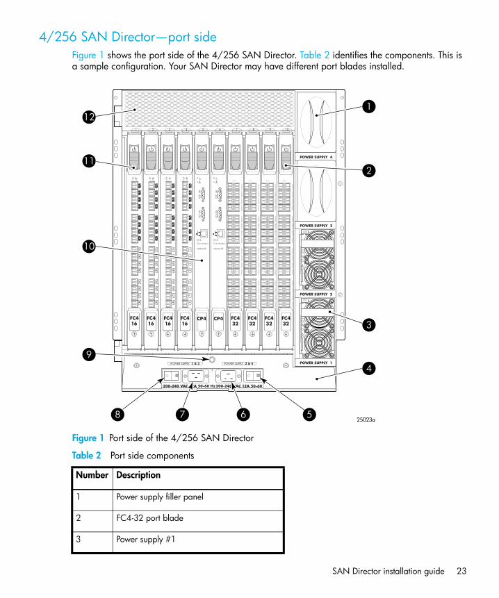
4/256 SAN Director—port sideFigure 1 shows the port side of the 4/256 SAN Director. Table 2 identifies the components. This is a sample configuration. Your SAN Director may have different port blades installed.
Figure 1 Port side of the 4/256 SAN Director
Table 2 Port side components
Number Description
1 Power supply filler panel
2 FC4-32 port blade
3 Power supply #1
POWER SUPPLY 2
POWER SUPPLY 3
POWER SUPPLY 4
POWER SUPPLY 1
1 2 3 4 5 6 7 8 9 10
200-240 VAC 12A 50-60 Hz200-240 VAC 12A 50-60 Hz
!
!
!
!
POWER SUPPLY 1 & 3 POWER SUPPLY 2 & 4
CP4
Link
10/100 Mb/s
!
Active CP
I O I O
I RS - 232
CP4
Link
10/100 Mb/s
!
Active CP
I O I O
I RS - 232
FC432
FC432
FC432
FC432
7
6
5
4
3
2
1
0
15
14
13
12
11
10
9
8
56-0000590-01 Rev A
!
FC416
7
6
5
4
3
2
1
0
15
14
13
12
11
10
9
8
56-0000590-01 Rev A
!
FC416
7
6
5
4
3
2
1
0
15
14
13
12
11
10
9
8
56-0000590-01 Rev A
!
FC416
7
6
5
4
3
2
1
0
15
14
13
12
11
10
9
8
56-0000590-01 Rev A
!
FC416
12
11
10
9
8 7 6 5
4
3
2
1
25023a

Overview24
4 Cable management comb
5 AC power switch (for power supplies2 and 4)
6 AC power connector (for power supplies2 and 4)
7 AC power connector (for power supplies1 and 3)
8 AC power switch (for power supplies 1and 3)
9 Grounding strap connector
10 CP4 card (control processor card)
11 FC4-16 port blade
12 Exhaust vent
Table 2 Port side components (continued)
Number Description

SAN Director installation guide 25
4/256 SAN Director—nonport sideFigure 2 shows the nonport side view of the 4/256 SAN Director. Table 3 identifies the components..
Figure 2 Nonport Side of the 4/256 SAN Director
10 pwr4
pwr3
pwr2
pwr1
987654321
9
8
7
6
5
4
321
MRO25024a
Overview26
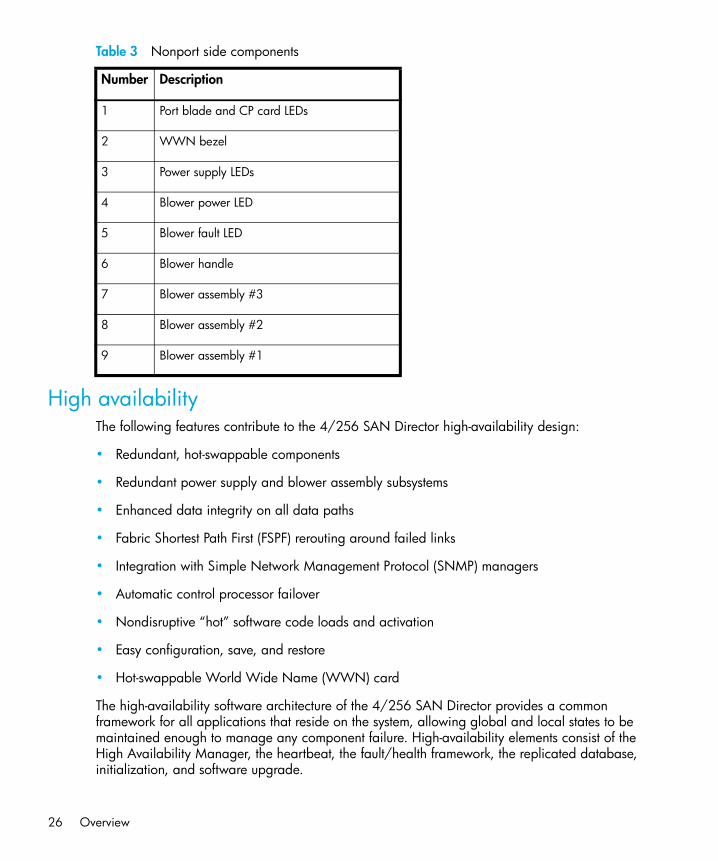
Table 3 Nonport side components
High availabilityThe following features contribute to the 4/256 SAN Director high-availability design:
• Redundant, hot-swappable components
• Redundant power supply and blower assembly subsystems
• Enhanced data integrity on all data paths
• Fabric Shortest Path First (FSPF) rerouting around failed links
• Integration with Simple Network Management Protocol (SNMP) managers
• Automatic control processor failover
• Nondisruptive “hot” software code loads and activation
• Easy configuration, save, and restore
• Hot-swappable World Wide Name (WWN) card
The high-availability software architecture of the 4/256 SAN Director provides a common framework for all applications that reside on the system, allowing global and local states to be maintained enough to manage any component failure. High-availability elements consist of the High Availability Manager, the heartbeat, the fault/health framework, the replicated database, initialization, and software upgrade.
Number Description
1 Port blade and CP card LEDs
2 WWN bezel
3 Power supply LEDs
4 Blower power LED
5 Blower fault LED
6 Blower handle
7 Blower assembly #3
8 Blower assembly #2
9 Blower assembly #1

SAN Director installation guide 27
The High Availability Manager controls access to the standby control processor, facilitates software upgrades, prevents extraneous switchover activity, closes and flushes streams as needed, provides flow control and message buffering, and supports a centralized active and standby state.
ReliabilityThe 4/256 SAN Director uses the following error detection and correction mechanisms to ensure the reliability of all data inside the chassis:
• All data inside the switch protected by the Error Detection and Correction mechanism, which checks for encoder errors and fault isolation (EDFI), such as cyclic redundancy checking (CRC), parity checking, checksum, and illegal address checking
• Power-on self-test (POST)
• Dual control processors that enable hot, nondisruptive fast firmware upgrades
• Each control processor contains two serial ports and one Ethernet port. Offline control processor diagnostics and remote diagnostics simplify troubleshooting. The standby control processor continuously runs diagnostics to ensure it is operational, should a failover be necessary.
• Inter-IC (I2C) monitoring and control
ServiceabilityThe 4/256 SAN Director provides the following features to enhance and ensure serviceability:
• Modular design with hot-swappable components
• Redundant flash memory that stores two firmware images per control processor
• Extensive diagnostics and status reporting, along with a serial port to support an external, country-specific modem for remote diagnostics and status monitoring
• Nonvolatile random-access memory (NVRAM), containing the HP serial number, manufacturer’s serial number, revision information, and part number information
• Background health-check daemon
• Memory scrubber, self test, and bus ping to determine if a bus is not functioning
• Watchdog timers
• Status LEDs
• Predictive diagnostics analysis through Fabric Watch
• SNMP integration with higher-layer managers

Overview28
Software featuresThe 4/256 SAN Director must be running Fabric OS 5.1.x or greater; and with the B-Series iSCSI Director Blade (FC4-16IP) installed, it must operate with Fabric OS 5.2.1b or greater.
The Fabric OS allows any Fibre Channel-compliant device to attach to the switches as long as it conforms to the device login, name service, and related Fibre Channel standards. Each operating environment requires that a Fibre Channel Host Bus Adapter (HBA) be available with a standards-compliant driver for proper interface to the fabric.
Fabric OS consists of a set of embedded applications running on top of an embedded real-time Linux operating system kernel. These applications are the name server, alias server, Simple Network Management Protocol (SNMP) agent, and several tasks to manage address assignment, routing, link initialization, fabric initialization, link shutdown, switch shutdown, and the user interface.
SecuritySecure telnet access is available using Secure Shell (SSH), a network security protocol for secure remote login and other secure network services over an insecure network.
Advanced Web Tools management is available through a secure browser using Secure Sockets Layer (SSL). The SSL security protocol provides data encryption, server authentication, message integrity, and optional client authentication for a TCP/IP connection. Because SSL is built into all major browsers and Web servers, installing a digital certificate turns on the SSL capabilities.
Network manageabilityThe 4/256 SAN Director has a single domain and is managed as a single element and appears as a single element to a Network Management System (NMS). The Director responds to its own IP address and appears as a separate entity to the Telnet protocol and SNMP.
All management interfaces, such as telnet, Advanced Web Tools, the Fabric Access Layer API, and Management Server, support a “port N within card M” naming scheme.
When SNMP devices send SNMP messages to a management console running SAN management software, the information is stored in a Management Information Base (MIB). Fabric OS 5.2.x supports the latest Fibre Alliance Fibre Channel Management (FCMGMT) and Storage Management Initiative (SMI) MIBs, which allow common information necessary for management software to provide information to a SAN administrator. Refer to the Fabric OS MIB reference manual for additional MIB information. Go to this document’s Preface for instructions on accessing the document via the web.

SAN Director installation guide 29
Port numberingExcept for the following cases, the area ID is equal to the port number:
• when performing a port swap operation
• when enabling Extended Edge PID mode on the Director. For more information on Extended Edge PID mode, refer to the HP StorageWorks Fabric OS administrator guide.
The 4/256 SAN Director uses the following port numbering schemes, see Figure 3:
• For the FC4-16 port blade— ports are numbered from 0 through 15 from bottom to top.
• For the FC4-32 port blade— ports are numbered from 0 through 15 from bottom to top on the left set of ports and 16 through 31 from bottom to top on the right set of ports.
• For the FC4-48 port blade— ports are numbered from 0 through 23 from bottom to top on the left set of ports and 24 through 47 from bottom to top on the right set of ports.
• For the FR4-18i—The sixteen physical Fibre Channel ports on this blade are numbered 0 through 15 from bottom to top. The two GbE ports are numbered from the bottom as Ge0 and Ge1. These ports, when fully configured, enable 16 VE_Ports or VEX _Ports and appear in the switchShow command as ports 16 through 31.
• For the FC4-16IP—The port numbering is divided between the two type of ports. At the bottom of the blade, note that Fibre Channel (FC) ports numbered from 0 through 7 bottom to top. Similarly, the next eight GbE ports number 0 through 7, bottom to top.
Slots number 1 through 10, from left to right when facing the port side of the Director. The CPs reside in slots 5 and 6 respectively.
Use ”Port numbering templates” on page 239 as a port numbering template for your SAN to easily identify how the ports are numbered. If you have a 16-port blade installed, cross out the extra ports displayed on the template.

Overview30
Figure 3 identifies the port numbering for a fully populated 4/256 SAN Director.
Figure 3 Fully populated 4/256 SAN Director with ports numbered
2.017
Link
10/100 Mb/s
Active CP
!
IOIO
IRS
-232
Link
10/100 Mb/s
Active CP
!
IOIO
IRS
-232
Slot 1 Slot 2 Slot 3 Slot 4 Slot 5 Slot 6 Slot 7 Slot 8 Slot 9 Slot 10
240112
113
114
115
241
242
243
22496
97
98
99
225
226
227
20880
81
82
83
209
210
211
19264
65
66
67
193
194
195
17648
49
50
51
177
178
179
16032
33
34
35
161
162
163
14416
17
18
19
145
146
147
1280
1
2
3
129
130
131
1324
5
6
7
133
134
135
14820
21
22
23
149
150
151
16436
37
38
39
165
166
167
18052
53
54
55
181
182
183
1368
9
10
11
137
138
139
15224
25
26
27
153
154
155
16840
41
42
43
169
170
171
18456
57
58
59
185
186
187
14012
13
14
15
141
142
143
15628
29
30
31
157
158
159
17244
45
46
47
173
174
175
18860
61
62
63
189
190
191
20476
77
78
79
205
206
207
22092
93
94
95
221
222
223
236108
109
110
111
237
238
239
252124
125
126
127
253
254
255
20072
73
74
75
201
202
203
21688
89
90
91
217
218
219
232104
105
106
107
233
234
235
248120
121
122
123
249
250
251
19668
69
70
71
197
198
199
21284
85
86
87
213
214
215
228100
101
102
103
229
230
231
244116
117
118
119
245
246
247

SAN Director installation guide 31
Optional hardware kitsTable 4 lists the 4/256 SAN Director optional hardware kits.
* premerger Compaq part number
NOTE: Note: A7446B, AE493A, A6515A, and A6516A are supported in the MP Router blade Fibre Channel ports and GbE FCIP ports. Router GbE connectivity is equivalent to 1000Base-SX (short wave) or 1000Base-LX (long wave). For GbE copper connectivity, refer to the Brocade Compatibility Matrix for supported copper SFPs.
Table 4 4/256 SAN Director orderable hardware
Accessory Part number
HP StorageWorks 4/256 SAN Director 16 Port 4Gb blade
A7990A
HP StorageWorks 4/256 SAN Director 32 Port 4Gb blade
A7991A
HP StorageWorks 4/48 SAN Director Port Blade
AG561A
HP StorageWorks B-Series MP Router Blade AG461A
HP StorageWorks B-Series iSCSI Director Blade
AG671A
2Gb Short wavelength SFP A6515A
4Gb Short wavelength SFP A7446B
4Gb Long wavelength SFP AE493A
2Gb Long wavelength SFP, 10 km A6516A
2Gb Long wavelength SFP, 35 km 300386-B21*
2m LC-to-LC multi-mode fc cable 221692-B21*
5m LC-to-LC multi-mode fc cable 221692-B22*

Overview32

SAN Director installation guide 33
2 Installing and configuring the 4/256 SAN DirectorThis chapter provides the following information:
• Unpacking and verifying carton contents, page 34• Installation overview, page 37• Setup tasks and estimated time required, page 38• Powering on the 4/256 SAN Director, page 53• Establishing a serial connection, page 55• Managing cables, page 57• Setting initial configuration parameters, page 61• Configure IP addresses for the 4/256 SAN Director, page 62• Establishing an Ethernet connection, page 65• Customizing a switch name, page 65• Setting the domain ID, page 66• Verifying the PID mode and connect to the fabric, page 66• Enabling software licenses, page 67• Backing up the configuration, page 67

Installing and configuring the 4/256 SAN Director34
Unpacking and verifying carton contentsUnpack and verify 4/256 SAN Director carton contents. See Figure 4 and Table 5..
Figure 4 Carton contents
NOTE: Order SFP transceivers separately from your authorized HP representative. The 4/256 SAN Director supports SWL, LWL, and ELWL transceivers. See Table 4 on page 31, ”4/256 SAN Director orderable hardware” for information about optional hardware kits.
SHR-2506C
1
2
3
4

SAN Director installation guide 35
Table 5 Carton contents checklist
Item Summary
1 Chassis, includes:
• Two Control Processor (CP) cards• Blade slot filler panels (included only in slots not filled by a port blade or CP card)• Two power supplies and power supply filler panels• Three blower assemblies• One WWN card and bezel• One cable management comb• Chassis door
2 Accessory Kit, includes the following
• One set of HP StorageWorks product documentation, Safety Guides, End User License Agreement and Warranty Guide.
• ESD grounding strap, sixteen cable management guides (pillars), and two power cord retainers
• RS-232 serial cable with an RJ-45 adapter
• Two AC power cords
• Two PDU power cords (not shown). (See ”Power requirements” on page 38 for information about PDUs.)

Installing and configuring the 4/256 SAN Director36
3 14U Rack Mount Kit Rails, includes the following:• Left rack mount shelf bracket, (1); Right rack mount shelf bracket (1)
• Left upper rack mount bracket assembly includes: Left upper rack mount bracket (flat); left upper rack mount bracket (L-shaped); screw (torque to 32 inch-pounds)
• Right upper rack mount bracket assembly includes: right upper rack mount bracket (flat); right upper rack mount bracket (L-shaped); screw (torque to 32 inch-pounds)
• M5 Tinnermans (0590-2318) and M5 Torx screws (0515-0671) are required rack mount kit hardware.
4 14U Rack Mount Kit hardware:
#10-32 x 5/16 Phillips flathead screws (8); #10-32 x 5/16 Phillips panhead screws with washers (4)
For use with an HP 42U rack (or racks with square holes): #10-32 x 5/16 retainer nuts; #1/4-20 x 0.500 Phillips panhead screws with glue (16); 0.375-inch square washers (16)
For use with rack with round holes: #10-32 clip nut (package of 20, only 4 required); #1/4-20 x 1/2 inch Phillips panhead screws with lockhead washers (16)
Table 5 Carton contents checklist (continued)
Item Summary

SAN Director installation guide 37
Installation overviewYou can install the 4/256 SAN Director in one of the following ways:
• As a stand-alone unit on a stable table or lab workbench
• In a rack using the 14U Rack Mount Kit supplied with the switch
Selecting an operating locationVerify that the switch location meets the following requirements:
• Adequate supply circuit, line fusing, and wire size, as specified by the electrical rating on the switch nameplate.
• Air flow of at least 350 cubic feet per minute, available in the immediate vicinity of the 4/256 SAN Director.
• If you are installing the switch in an HP rack:
• All equipment installed in the rack should have a reliable branch circuit ground connection, and should not rely on a connection to a branch circuit, such as a power strip.
• The rack should be balanced, and the installed equipment should be within the rack’s weight limits. Ensure that the rack is mechanically secured to insure stability in the event of an earthquake.
Cooling requirementsInstall the switch so that air intake and exhaust for all components in the rack is flowing in the same direction.
NOTE: To ensure adequate cooling, install the chassis with the port side facing the aisle into which exhaust air is released (usually called the service aisle). This prevents the fans from pulling in heated exhaust air.

Installing and configuring the 4/256 SAN Director38
Power requirementsTwo AC power cords connect to the switch. The AC power source must meet these requirements:
NOTE: Installing each power cord using two separate sources ensures power supply redundancy.
• 200 to 240 VAC, 50–60 Hertz
• Protected by a circuit breaker in accordance with local electrical codes
• Supply circuit, line fusing, and wire size that are adequate according to the electrical rating on the chassis nameplate
• Grounded AC outlets installed by a licensed electrician and compatible with the power cords
The switch includes a universal power supply capable of functioning worldwide without voltage jumpers or switches. The power supply is auto ranging in terms of accommodating input voltages and line frequencies.
HP recommends connecting two optional Power Distribution Units (PDUs) to the switch for power redundancy. The recommended PDU is E7671A. HP recommends that you do not connect the switch to the wall, because it would require two dedicated wall outlets. Using the PDU, you can connect more devices to a power source.
Two jumper cables (C19-C20) are provided to connect from the switch to the PDU. The recommended power cords to connect from the PDU to the wall are E7803A, E7805A, E7806A, E7808A, and E7809A.
Setup tasks and estimated time requiredTable 6 describes the main installation and setup tasks and the estimated time required for each, based on a fully populated 4/256 SAN Director (with 384 Fibre Channel ports). Configurations containing fewer than 384 ports require less time. These time estimates assume a prepared installation site and appropriate power and network connectivity.

SAN Director installation guide 39
Table 6 Installation tasks, time and items required
Installation Task Time Estimate Items Required
Unpacking the Director 30 minutes 1/2-in. socket wrench (to remove pallet bolts)
#2 Phillips screwdriver(for cable management comb)
Pallet jack
Hydraulic lift or assisted lift, able to raise to a minimum of 55 in. (140 cm), with a minimum capacity of 113 kg (250 lb). The 4/256 SAN Director weighs 98 kg (216 lb) without media but can weigh considerably more depending on the media installed.
Installing rack mount kit 30 minutes See ”Installing the switch in a rack”.
Mounting and securing Director in rack 30 minutes
Installing power cables and serial cable and configuring IP addresses
20 minutes Power cables and serial cable (provided in 4/256 SAN Director accessory kit)
Workstation computer with a serial port or terminal server port and a terminal emulator application (such as HyperTerminal)
Ethernet IP addresses for the switch (1) and for each CP blade (2): total three addresses
Installing Ethernet cable(s) and configuring the 4/256 SAN Director name, policies, domain ID, PIDs, or additional system parameters
20 minutes Ethernet cabling (optional) is required for telnet access. All other configuration parameters optional.
See the HP StorageWorks Fabric OS administrator guide for PID information.
Installing SFP optical transceivers 30 minutes SFP optical transceivers
Attaching fiber optic cables, cable ties, and cable guides
60 minutes Fiber optic cables, cable ties, and cable pillars

Installing and configuring the 4/256 SAN Director40
Installing the switch as a stand-alone unitThe following items are required:
• 4/256 SAN Director
• AC power cords and cables supplied with the switch
Removing the chassis door
CAUTION: You must remove the chassis door before lifting the chassis off the pallet.
See Figure 5 for an illustration of the complete chassis door removal sequence.
1. Open the door to a 90° angle.
2. Push the spring-loaded lever on the upper hinge up and into the notch in the hinge.
3. Push the spring-loaded lever on the lower hinge down and into the notch in the hinge, while supporting the door to prevent it from falling.
Figure 5 Sequence for detaching the chassis door from the hinges
NOTE: Put the chassis door aside. You will need to reinstall it after moving the switch off the pallet.
4. Position the pallet so that the bottom of the chassis is level with the installation surface.
1 2 3
SHR-2508A

SAN Director installation guide 41
5. If the chassis is on a pallet jack or lift, stabilize the pallet jack or lift to prevent it from moving during the transfer.
WARNING! A fully populated chassis (384 ports) weighs approximately 216 lbs (98 kg) without media, and requires a minimum of two people to safely slide it from one surface to another.
Installing the switch on a flat surfaceUse these steps to install the switch on a flat surface.
NOTE: The switch must be placed on a stable, flat surface, with the blower side of the chassis having access to cool air. Orient the switch so that the port side faces the service aisle.
1. Remove the switch chassis door, if you have not already done so. See ”Removing the chassis door” on page 40.
2. Place the switch on a flat, sturdy surface like a table or lab bench.
3. Connect the two power cables to the power supply inlets on the switch.
TIP: HP recommends powering the switch using two separate power sources to ensure redundancy.
4. Connect the two power cables to corresponding power outlets. Make sure that the power cables are routed so that they are not exposed to stress.
5. Turn on power to the switch.
The switch automatically runs a Power On Self Test (POST).
NOTE: Do not connect the switch to the network until the IP address is set correctly.
6. Reinstall the chassis door as described in the section ”Reinstalling the chassis door” on page 52.

Installing and configuring the 4/256 SAN Director42
Installing the switch in a rackThese sections contain specific information about installing the 4/256 SAN Director in an HP 10,000 series or HP System/e rack.
WARNING! For safety reasons, when installing this product in an equipment rack, you must consider rack stability against tipping. Please refer to the user manual provided with the equipment rack to determine rack stability; the manual is available through the HP web site: http://www.hp.com/racksolutions/prodinfo/racks/index.html.
If the necessary stability is not achieved through the placement of additional equipment, the equipment rack must be anchored to the building structure before operation.
HP only supports a maximum of two SAN Director switches in a rack.
Pre-installation checklistReview the following checklist before installing the switch.
• Prepare a site plan.
• Verify that required technical personnel (two technicians) are available and scheduled for the installation.
• Obtain the required fiber-optic cables (multimode or single-mode). Verify cable length and required connectors.
• If applicable, obtain the necessary remote workstations or Simple Network Management Protocol (SNMP) workstations. Workstations are customer-supplied and connected through a corporate or dedicated LAN.
• Verify that the front panel air temperature does not exceed 40°C (104°F) during operation.
• Verify that all equipment installed in the rack has a reliable branch circuit ground connection, and does not rely on a connection to a branch circuit, such as a power strip.
• Verify that the rack is balanced.
• Check that the rack is mechanically secured to insure stability in the event of an earthquake.
Items required for installationLocate the following items before beginning the installation procedure:
• Lift device—A minimum of two people and a hydraulic or assisted lift are required to move the switch from the pallet to its operating location.

SAN Director installation guide 43
• Two power outlets—Identify one power outlet for each of the two power cords. Installing the power cords at two separate sources ensures power supply redundancy.
• Torque driver—Required to secure the 14U Rack Mount Kit hardware to the rack rails.
• Fiber optic protective plugs—For safety and port transceiver protection, fiber optic protective plugs must be inserted in all 4/256 SAN Director ports without Fiber optic cables attached.
• Standard flat-tip and cross-tip Phillips screwdrivers—Required to remove, replace, adjust or tighten various FRUs, chassis, or rack components.
• Electrostatic discharge (ESD) grounding strap—Required when working in and around the switch card cage. Use the ESD strap supplied with the switch.
• Maintenance terminal (desktop or notebook computer)—Required to configure switch network addresses and acquire event log information through the serial port. Computer requirements include:
• Microsoft® Windows® 2000, Microsoft® Windows XP, Microsoft® Windows NT 4.0, or Windows Millennium Edition® operating system installed
• RS-232 serial communication software (for example, ProComm Plus or HyperTerminal)
• HP-supported racks—HP 9,000, HP 10,000 series and HP System/e racks. HP only supports a maximum of two SAN Director switches in a rack.
Important rack mount safety guidelinesReview the following rack mount guidelines before proceeding with the installation.
WARNING! A fully populated 4/256 SAN Director (384 ports) weighs approximately 216 lbs (96 kg) and requires a minimum of two people and a hydraulic or assisted lift to install it.
Do not use any of the bays (such as the power supply or blower assembly bays) for leverage.To ensure adequate cooling, install the chassis with the nonport side facing the air-intake aisle. This prevents the blowers from pulling in heated exhaust air.
If the switch is installed in a cabinet, verify that the cabinet is balanced and secured mechanically and that the removal and installation procedure will not compromise cabinet stability.
• Provide a space that is 14 rack units (14U) high, 29 in. deep, and 19-in. wide. 1U is equal to 1.75 in.
• Plan to install the 4/256 SAN Director with the nonport side facing the air-intake aisle.

Installing and configuring the 4/256 SAN Director44
NOTE: The 4/256 SAN Director can be installed facing either direction, if serviceability and cooling requirements are met.
• Plan for cable management before installing the chassis (see ”Managing cables” on page 57).Cables can be managed in a variety of ways, such as by routing cables below the chassis, to either side of the chassis, through cable channels on the sides of the cabinet, or by using patch panels.
• Verify that two dedicated electrical branch circuits with the following characteristics are available:• 200–40 VAC, 50–60 Hz• Protected by a circuit breaker in accordance with local electrical codes• Supply circuit, line fusing, and wire size adequate to the electrical rating on the chassis
nameplate• Location close to the 4/256 SAN Director chassis and easily accessible• Grounded outlets installed by a licensed electrician, compatible with the power cords
NOTE: To maximize fault tolerance, connect each power cord to a separate power source.
• Ensure that the blowers in the 4/256 SAN Director have access to a total minimum air flow of 350 cu ft per minute (595 cu m per hour).
• Ensure that the air intake and exhaust vents have a minimum of 2 in. of airspace.• Ensure that the air temperature on the air intake side is less than 40 degrees Celsius (104
degrees Farenheit) during operation.• Verify that the additional weight of the chassis does not exceed the rack’s weight limits.
Installing the switch in HP specified racksUse the following procedure to install the 4/256 SAN Director in an HP 10,000 series or HP System/e rack using the 14U Rack Mount Kit supplied with the switch. Allow approximately 45 minutes to complete this procedure.
NOTE: These instructions describe how to install the switch in the bottom area of the rack (section closest to the floor). You may need to orient 14U Rack Mount Kit hardware based on your particular rack’s configuration.
Attaching the rack mount shelf bracketsUse these steps to install the rack mount shelf brackets.

SAN Director installation guide 45
NOTE: You can install up to two HP StorageWorks Director class switches in the HP 10,000 series or HP System/e racks.
1. If you have not already done so, remove the chassis door. See ”Removing the chassis door” on page 40.
2. Locate the left and right rack mount shelf brackets. Refer to Figure 4 and Table 5 to identify the hardware.
3. Loosen the adjusting screws on the left and right rack mount shelf brackets, and adjust the length of the brackets according to the depth of the rack. See Figure 6.
4. Locate the small, round marker holes on the rack rails. Each marker hole delineates the beginning of one rail unit, or U. Leave 1U of space free at the bottom of the rack.
5. Count up five square holes from the 1U location. Align the left rack mount shelf brackets with the fifth square hole.
6. Attach the rack mount shelf brackets:
a. For rails with round holes, position the left and right rack mount shelf brackets with notched portion toward exhaust aisle (see Figure 6) and attach to rack rails, using six 1/4-20 x 0.500-inch (1.27 cm) screws with lock washers per bracket (two on the notched end and four on the other end).
b. For rails with square holes, attach the left rack mount shelf bracket to the rack rails using six 1/4-20 x 0.500-inch screws and six square washers. See Figure 6.
CAUTION: All 14U Rack Mount Kit hardware and screws are supplied with the switch. Use the exact screws specified in the procedure. Using longer screws may damage the chassis.

Installing and configuring the 4/256 SAN Director46
Figure 6 Installing the left and right rack mount shelf brackets
7. Tighten the screws to a torque of 80-inch pounds.
8. Repeat step 5 through step 7 to install the right rack mount shelf bracket.
NOTE: When finished securing the rack mount shelf brackets, remember to tighten the adjustment screws you loosened in step 3, and torque to 32 inch-pounds.
1 Left rack mount shelf bracket
2 Adjusting screws
3 Right rack mount shelf bracket
4 1/4-20 x .500-inch screws and washers (6)
SHR-2509A
1
3
2
4

SAN Director installation guide 47
Attaching the retainer nuts—for rails with square holesIf you are installing the 14U Rack Mount Kit in rails with square holes (like the 10,000 series 42U rack), attach retainer nuts to vertical rails on service side of the rack as follows.
1. First, count up 41 square holes from the 1U location.
2. Attach the four retainer nuts to the two rails at the front of the rack (service aisle side). See Figure Figure 7.
Figure 7 Installing the retainer nuts on the rails
Attaching the clip nuts—for rails with round holesIf you are installing the 14U Rack Mount Kit in rails with round holes, use the instructions in this section. Attach the clip nuts to the vertical rails on the service side of the rack as follows.
1. Count up 41 round holes from the 1U location.
2. Attach the four clip nuts to the two rails at the front of the rack (service aisle side). See Figure 7.
1 Upper retainer nuts, installed in hole #41
2 Lower retainer nuts, installed in hole #9
3 1U location
1
3
2

Installing and configuring the 4/256 SAN Director48
NOTE: Cables can be routed down through the cable management comb or through the holes in the sides of the chassis. If the cables will be routed down through the cable management comb, allow adequate space below the chassis for cable management.
Attaching the upper rack mount bracket assemblies to the chassisUse these steps to attach the upper rack mount brackets to the chassis. The upper rack mount bracket assemblies consist of the following:
• One right flat upper rack mount bracket attached to an L-shaped bracket
• One left flat upper rack mount bracket attached to an L-shaped bracket
NOTE: To compete this procedure, you must first detach the L-shaped brackets from the upper rack mount bracket assemblies.
1. Use a Phillips head screwdriver to remove the screws securing the left and right upper rack mount brackets to the L-shaped brackets. Detach the L-shaped brackets from the assembly and put them aside.
NOTE: You reinstall the L-shaped brackets to the rack rails in step 5.
2. Save the screws for attaching the bracket assemblies to the chassis (see step 1 in the section ”Securing the chassis to the rails” on page 51).
3. Use four #10-32 x 5/16 inch screws to secure the right and left flat upper rack mount brackets to the chassis. See Figure 8.
NOTE: Orient the slotted holes in the brackets toward the blower side of the chassis (see Figure 8 for orientation).

SAN Director installation guide 49
Figure 8 Attaching the left and right flat upper rack mount brackets
4. Tighten the screws and torque to 32 inch-pounds.
5. Attach the two L-shaped brackets to the rack rails farthest from the service aisle. See Figure 9.
• For rails with square holes: Attach the two L-shaped brackets to the rack rails with two of the #1/4-20 x 1/2 inch Phillips panhead screws and two square washers per bracket. Tighten the screws to a torque of 80 inch-pounds.
• For rails with round holes: Attach the two L-shaped brackets to the rack rails using two of the #1/4-20 x 1/2 inch Phillips panhead screws per bracket. Tighten the screws to a torque of 80 inch-pounds.
6. Route any cables or cords through the rack or along any other route that will be difficult to reach after the chassis is installed. Leave enough cable allowance to plug and unplug cables from switch.
1 Left flat upper rack mount bracket
2 #10-32 x 5/16 inch screws (4)
3 Detached L-shaped brackets (1 of 2)
4 Right flat upper rack mount bracket
SHR-2511A
1
2
3
4

Installing and configuring the 4/256 SAN Director50
Figure 9 Attaching L-shaped brackets to rails
Finalizing the rack mount procedureThis section tells you how to slide the switch into the rack and secure the chassis to the rack rails.
Sliding the switch into the rack1. Before lifting the chassis into the rack, determine an easy access route for cables or cords. Make
sure that cables do not get pinned under the weight of the chassis.
2. Position the lift device next to the switch.
3. Position one technician at the front of the chassis, and the second technician at the rear of the chassis. Carefully move the chassis onto the lift device.
1 Two L-shaped brackets
2 Aligning top screw in hole #37
3 1/4-20 x 1/2 inch Phillips panhead screws and square washers
SHR-2512A
1
2
3

SAN Director installation guide 51
4. Use the lift device to raise the chassis until the bottom of the chassis is level with the shelf-like surfaces of the rack mount shelf brackets.
5. Slide the chassis onto the two rack mount shelf brackets.
Securing the chassis to the rails1. Attach the two flat upper rack mount brackets (that you installed on the chassis earlier) to the two
L-shaped brackets installed onto the rack rails. Use the two screws set aside in step 1 of ”Attaching the upper rack mount bracket assemblies to the chassis” on page 48. See Figure 10.
Figure 10 Attaching the upper rack mount bracket to the L-shaped brackets
2. Tighten screws, and torque to 32 inch-pounds.
SHR-2513A

Installing and configuring the 4/256 SAN Director52
3. Secure the chassis port side to the rack rails using two #10-32 x 5/8 inch screws on each side.
Figure 11 Securing the chassis port side to rack rails
4. Tighten the screws, and torque to 32 inch-pounds. See Figure 11 for screw locations.
Reinstalling the chassis door1. Verify that the spring-loaded pins on both door hinges are retracted (push levers into notches).
2. Align the door hinges with the chassis portion of the hinges.
3. Push the levers out of the notches to release the pins.
SHR-2514A

SAN Director installation guide 53
Powering on the 4/256 SAN Director
NOTE: If using a modem with the 4/256 SAN Director, it needs to be connected prior to powering on the switch. To install a modem, refer to Setting up and installing modems, page 155.
To provide power to the 4/256 SAN Director:
1. Verify that the ON/OFF switch for each port blade and CP card are in the ON position.
2. Verify that the AC switch covers are installed over the AC switches. These clear plastic covers fit over the AC switches with their edges tucked underneath the outlet covers; they prevent the AC switches from being powered on or off accidentally (see Figure 12).
3. Connect the AC power cord retainers to the chassis: orient a retainer against the AC panel as shown in Figure 12, place the retainer tabs under the two jack screws on either side of the power receptacle, and tighten the screws. Repeat for the other retainer (note that the power cord retainers are oriented in the same direction as the power receptacles).

Installing and configuring the 4/256 SAN Director54
Figure 12 AC panel and power cord retainers
Table 7 AC panel components
Number Description
1 AC switch
2 AC power receptacle
3 Jack screw
4 Clamping screw
5 AC switch cover
6 Power cord retainer
7 Retainer attaching screw
8 Clamping screw
!
200-240 VAC 12A 50-60 Hz
POWER SUPPLY 1 & 3
POWER SUPPLY 2 & 4
200-240 VAC 12A 50-60 Hz
POWER S
8
7
6
5
4
32
1
MRO25026a

SAN Director installation guide 55
4. Loosen the clamping screw on each retainer, insert the power cords through the retainers into the power receptacles on the 4/256 SAN Director, and tighten the clamping screws. The power cords are designed to bend to the left, so each should route to an opposite side of the chassis.
5. Ensure that the power cord has a minimum service loop of 6 inches available at the connection to the switch and is routed so that it is not exposed to stress.
6. Connect the power cords to a power source with voltage of 200 to 240 VAC, 47 to 63 Hz.
7. Flip both AC power switches to 1. The AC power switches light up green when switched on and power is supplied.
The 4/256 SAN Director automatically performs a power-on self-test (POST) by default each time it is powered on. POST takes approximately 10 minutes and is complete when indicator light activity returns to the standard state. For information about LED patterns, refer to ”Monitoring system components” on page 63.
You can bypass POST by using the fastBoot command. You can also disable POST for successive reboots on the switch using the diagDisablePost command.
CAUTION: To prevent a potential IP address conflict, do not connect the 4/256 SAN Director to the network until the IP addresses are configured. Refer to ”Setting initial configuration parameters” on page 61 for additional information. Allow the 4/256 SAN Director to run for 10 minutes (minimum) to complete POST after powering on before you power off.
Establishing a serial connectionInitial communication to a 4/256 SAN Director switch requires a serial connection. Use these steps to establish a serial connection and log in to the Director:
1. Verify that the 4/256 SAN Director is powered on and that POST is complete by verifying that all power LED indicators on the port blades and CP4 cards are displaying a steady green light.
2. Use the serial cable provided with the 4/256 SAN Director to connect the console port on the active CP4 card to a computer workstation.
The console port is the second serial port from the top of the CP4 card; the active CP4 card is indicated by an illuminated (blue) LED. The “Active CP” LED in the standby CP card should be off (not illuminated).
The console port is intended primarily for use during the initial setting of the IP address and for service purposes. If necessary, the adapter on the serial cable can be removed to allow for an RJ-45 serial connection.
3. Access the Director using a terminal emulator application (such as HyperTerminal on Windows 95, 2000, or NT or TERM in a UNIX environment).
4. Disable any serial communication programs running on the workstation (such as synchronization programs).

Installing and configuring the 4/256 SAN Director56
5. Open the terminal emulator application and configure as follows:
For most MS Windows systems:
• Bits per second:9600
• Databits:8
• Parity:None
• Stop bits:1
• Flow control:None
For most UNIX systems, type the following string at the prompt:
tip /dev/ttyb -9600
When the terminal emulator application stops reporting information, press Enter. You will receive the following login prompt:
CP0 Console Login:
6. Log in to the 4/256 SAN Director as admin. The default password is “password”. At the initial login, the user is prompted to enter new admin and user passwords. Make sure to write down the passwords and keep this information in a secure location.
7. (Optional) Modify passwords, if desired. Passwords can be 8 to 40 characters long. They must begin with an alphabetic character. They can include numeric characters, the dot (.), and the underscore (_). Passwords are case-sensitive, and they are not displayed when you enter them on the command line. To skip modifying the password, press Ctrl-C. For more information on passwords, refer to the HP StorageWorks Fabric OS administrator guide.
8. Check the “Active CP” LED on the CP cards in slots 5 and 6, or type haShow to verify which CP card is active.
The configuration can be modified only through a login session to the active CP card.
swDir:admin> hashowLocal CP (Slot 6, CP1): ActiveRemote CP (Slot 5, CP0): Standby, HealthyHA enabled, Heartbeat Up, HA State synchronized

SAN Director installation guide 57
Managing cablesThe cable management comb and shortened chassis door introduced in the 4/256 SAN Director allow for simple cable management. The comb allows additional space between the chassis and shelf and can be installed without service disruption. The shortened chassis door design enables the fiber cables to exit the front of the vertical rack mounting rails.
The 4/256 SAN Director cables can be managed in a variety of ways, including the following:
• Routed down through the cable management comb
• Routed out either side of the chassis
• Cable channels on the sides of the cabinet
• Patch panels
Two items are provided to assist with cable management:
• Cable management comb
• Cable guides (pillars)

Installing and configuring the 4/256 SAN Director58
Cable management combThe cable management comb is attached to the chassis under the chassis door, and is used to route the power cables and other cables down below the chassis or out the sides of the chassis see Figure 13.
Figure 13 Cable management comb installed in a 4/256 SAN Director
Table 8 Cable management comb components
Number Description
1 Chassis
2 Cables
POWER SUPPLY 1
200-240 VAC 12A 50-60 Hz200-240 VAC 12A 50-60 Hz
POWER SU
PPLY 1
& 3
POWER SU
PPLY 2
& 4
POWER SUPPLY 1
!
!
POWER SUPPLY 2
!
!
POWER SUPPLY 3
!
!
POWER SUPPLY 4
!
!
Link
10/100 Mb/s
Active C
P
!
I O I O
I RS - 232
Link
10/100 Mb/s
Active C
P
!
I O I O
I RS - 232
!
3d
2c
1
b
0a
7d
6c
5
b
4a
11d
10c
9
b
8 a
15d
14c
13
b
12a
1
2
3
4
5
6
7
8
9
10
2
3
4
1
25040a

SAN Director installation guide 59
Cable guides (pillars)Cable guides (pillars) are provided with the 4/256 SAN Director, and can be used to organize the port cables into logical groups, such as according to port quads (sets of four neighboring ports). The cable guides do not attach to the chassis (see Figure 14).
NOTE: Cable pillars are not supported when using the FC4-32 or FC4-48 port blades because the cable count is too dense, leaving no room for the cable pillars. Instead, you should use velcro tabs to group cables for the FC4-32 or FC4-48 port blades
Figure 14 Cable guides (pillars) used to group cables
The cable guides serve to keep the cables evenly spaced and to hold them away from the port blades, making card replacement easier and preventing the cables from bending to less than the minimum bend radius.
3 Velcro straps
4 Cable management comb
Table 8 Cable management comb components (continued)
Number Description
scale: .50" = 1"
25042a

Installing and configuring the 4/256 SAN Director60
CAUTION: Do not route the cables in front of the air exhaust vent, which is located at the top of the port side of the chassis.
Arrange the cables so that the minimum bend radius is not exceeded; for a 50-micron cable, the minimum bend radius is 2 inches under full tensile load and 1.2 inches with no tensile load.
Tie wraps are not recommended for optical cables because they are easily overtightened and can break the optical cables.
To keep LEDs visible and make it easy to replace components, route cables down in front of the cards, not across adjacent cards or in front of the power supplies. Figure 13 provides an example in which cables for each card are routed in front of that card and are out of the way of other components.
Leave at least one meter of slack for each fiber optic cable. This provides room to remove and replace the port blade, allows for inadvertent movement of the rack, and helps prevent the cables from being bent to less than the minimum bend radius.
Use the cable guides provided with the 4/256 SAN Director to group the cables. These guides help to keep individual ports accessible by keeping the cables evenly spaced. If ISL Trunking is in use, grouping the cables by trunking group is recommended. The ports are color-coded to indicate which ports can be used in the same ISL Trunking group: four ports marked with solid black ovals alternate with four ports marked with oval outlines.
NOTE: ISL Trunking is a Fabric OS feature that enables distribution of traffic over the combined bandwidth of up to eight ISLs between two directly adjacent switches, while preserving in-order delivery.

SAN Director installation guide 61
A minimum length is required for cables that connect the 4/256 SAN Director ports to device ports, as described in Table 9:
Setting initial configuration parametersThe 4/256 SAN Director must be configured before it is connected to the fabric, and all of the configuration commands must be entered through the active CP card. The 4/256 SAN Director configuration includes the following parameters:
• IP address and subnet mask for the chassis
• IP addresses, host names, subnet masks, and gateway addresses for both CP cards
• Director name
• Domain ID for the Director (optional)
• WWN for the Director
The Director WWN is initially set by the factory to match the license ID (which is based on the chassis serial number). The WWN can be changed but the license ID cannot be modified.
The configuration information is automatically mirrored to the standby CP card—allowing the most current configuration to remain available even if the active CP card fails. The configuration information for the switch is stored in the WWN card and the flash memory of the CP cards. The configuration can be backed up to a workstation (uploaded) and then downloaded to the active CP card if necessary.
Table 9 Supported cable speeds and distances
Cable type Speed Minimum distance Maximum distance
Single Mode 9 microns 2 Gb/sec 2 m 10,000 m
4 Gb/sec 2 m 10,000 m
Multi Mode 50 microns 2 Gb/sec 0.5 m 300 m
4 Gb/sec 0.5 m 150 m
62.5 microns 2 Gb/sec 0.5 m 150 m
4 Gb/sec 0.5 m 70 m

Installing and configuring the 4/256 SAN Director62
The basic steps required for the initial configuration are:
1. Log in to the Director.
2. Set up IP addresses.
3. Establish an Ethernet connection.
4. Specify a Director name.
5. Specify a domain ID for the Director.
6. Verify that the PID mode matches the fabric and connect the Director to the fabric.
7. Enable software licenses as necessary.
8. Back up the configuration.
Configure IP addresses for the 4/256 SAN DirectorThe 4/256 SAN Director requires three IP addresses, which are configured using the ipAddrSet command. IP addresses are required for both CP cards (CP0 and CP1) and for the single logical switch (shown as SWITCH under the ipAddrShow command) in the 4/256 SAN Director.
NOTE: The IP and gateway addresses must reside on the same subnet. The same gateway address must be used for both CP cards (these gateway addresses are referenced for the IP addresses).
Resetting an IP address while the 4/256 SAN Director has active IP traffic such as Fabric Manager, Fabric Watch, SNMP, or other applications can cause traffic to be interrupted or stopped. Changing the IP address causes a domain address format RSCN to be issued.
The addresses 10.0.0.0 through 10.0.0.255 are reserved and used internally by the switch. External IPs cannot use these addresses either.
The default IP addresses and host names for the 4/256 SAN Director are as follows:
• 10.77.77.75 / CP0 (the CP card in slot 5 at the time of configuration)
• 10.77.77.74 / CP1 (the CP card in slot 6 at the time of configuration)
Configuration changes can only be made through the active CP card. If the CP card in slot 5 is not the active CP card, disconnect the serial cable and connect it to the CP card in slot 6; then, log in as admin. The default password is “password.”

SAN Director installation guide 63
Follow these steps to configure the IP addresses for both CP cards (from the active CP card):
1. Login to the active CP as admin using the Serial Cable connection.
2. Set up the Director IP address by entering the ipaddrset -sw 0 command:
Enter the requested information at the prompts.
TIP: Unlike the Core Switch 2/64 or SAN Director 2/128, the only valid configuration for the 4/256 SAN Director is as a single domain (single logical switch), so you only need to specify the -sw 0 IP address. There is no -sw 1 in the 4/256 SAN Director.
3. Set up the CP0 IP address by entering the ipaddrset -cp 0 command:
Enter the requested information at the prompts.
4. Set up the CP1 IP address by entering the ipaddrset -cp 1 command:
Enter the requested information at the prompts.
swDir:admin> ipAddrSet -sw 0
swDir:admin> ipAddrSet -cp 0
swDir:admin> ipAddrSet -cp 1

Installing and configuring the 4/256 SAN Director64
Following is a sample IP configuration:
5. Type reboot at the prompt to reboot the 4/256 SAN Director.
The serial port can be used to monitor error messages through a serial connection. It is not recommended as a command interface during normal operations. If this port is not going to be in ongoing use, remove the serial cable and protect the port from dust by replacing the shipping cap.
swDir:admin> ipaddrset -sw 0Ethernet IP Address [0.0.0.0]: 123.123.123.120Ethernet Subnetmask [0.0.0.0]: 123.123.123.123Fibre Channel IP Address [0.0.0.0]: Fibre Channel Subnetmask [0.0.0.0]: Issuing gratuitous ARP...Done.Committing configuration...Done.
swDir:admin> ipaddrset -cp 0Host Name [cp0]:Ethernet IP Address [10.77.77.75]: 123.123.123.121Ethernet Subnetmask [0.0.0.0]: 123.123.123.123Gateway IP Address [0.0.0.0]: 123.123.123.124IP address is being changed...Done.Committing configuration...Done.
swDir:admin> ipaddrset -cp 1Host Name [cp1]:Ethernet IP Address [10.77.77.74]: 123.123.123.122Ethernet Subnetmask [0.0.0.0]: 123.123.123.123Gateway IP Address [0.0.0.0]: 123.123.123.124IP address of remote CP is being changed...Done.Committing configuration...Done.
swDir:admin> reboot

SAN Director installation guide 65
Establishing an Ethernet connectionAfter using a serial connection to configure the IP addresses for the 4/256 SAN Director (see ”Configure IP addresses for the 4/256 SAN Director” on page 62), you can connect the active CP card to the local area network (LAN) if desired.
NOTE: Connecting the CP cards to a private network/VLAN is recommended.
By establishing an Ethernet connection, you can complete the 4/256 SAN Director configuration using either the serial session, telnet, or Advanced Web Tools. Make sure that the 4/256 SAN Director is not modified from other connections at the same time.
Use these steps to establish an Ethernet connection to the 4/256 SAN Director:
1. Remove the shipping plug from the Ethernet port on the active CP card.
2. Insert one end of an Ethernet cable into the Ethernet port.
3. Connect the other end to an Ethernet 10/100 Base-T LAN.
The 4/256 SAN Director can now be accessed by remote connection using any of the available management tools, such as telnet, Advanced Web Tools, or the optional Fabric Manager software.
4. To complete any additional 4/256 SAN Director configuration procedures through a telnet session, log in to the switch by telnet, using the admin login. The default password is “password”.
Customizing a switch nameThe switch name of the 4/256 SAN Director can be up to fifteen characters long; can include alpha, numeric, and underscore characters; and must begin with an alpha character. The default name for the 4/256 SAN Director is “swDir”.
NOTE: Changing the name causes a domain address format RSCN to be issued.
Use these steps to customize the name, follow these steps.
1. Type switchName followed by the new name in quotes.
2. Record the new name for future reference.
swDir:admin> switchName "swDirector5"Committing configuration...Done.swDirector5:admin>

Installing and configuring the 4/256 SAN Director66
Setting the domain IDEach switch in the fabric must have a unique Domain ID. The Domain ID can be set by typing the configure command. You can also allow the Domain ID to be automatically set. The default Domain ID for the 4/256 SAN Director is “1”. Use the fabricShow command on the fabric to view the current domain IDs and determine what domain value you want to set.
Use these steps to set the Domain ID.
1. Type fabricShow to determine the current Domain IDs available.
2. Type switchDisable to disable the 4/256 SAN Director.
3. Type configure.
4. Type y at the “Fabric parameters” prompt:
5. Enter a unique Domain ID:
6. Complete the remaining prompts or press Ctrl+D to accept the other settings and exit.
7. Type switchEnable to reenable the 4/256 SAN Director.
Verifying the PID mode and connect to the fabricBefore connecting the 4/256 SAN Director to the fabric, verify the port identifier (PID) mode on the switch matches the other switches in the fabric. This parameter must be set identically on all switches in the fabric. This parameter is set using the configure command. For more information on PID mode, refer to the HP StorageWorks Fabric OS administrator guide.
Use these steps to connect the 4/256 SAN Director to the fabric.
1. Add SFP transceivers and cables to the fibre channel ports, as required.
The ports are color-coded to indicate which ones can be used in the same port group for trunking; trunking port groups can be up to 8 ports. Trunk groups are displayed by shaded or nonshaded ports. The ports and cables used in trunking groups must meet specific requirements. For a list of these requirements, refer to the “ISL Trunking” section of the HP StorageWorks Fabric OS administrator guide.
2. Position one of the SFP transceivers so that the key is oriented correctly to the port. Insert the transceiver into the port until it is firmly seated and the latching mechanism clicks.
Transceivers are keyed so that they can only be inserted with the correct orientation. If a transceiver does not slide in easily, ensure that it is correctly oriented. For instructions that are specific to the transceiver model, refer to the transceiver manufacturer’s documentation.
Fabric parameters (yes, y, no, n): [no] y
Domain: (1..239) [1] 3

SAN Director installation guide 67
3. Position a cable so that the key (the ridge on one side of the cable connector) is aligned with the slot in the transceiver; then, insert into the transceiver until the latching mechanism clicks.
Cables are keyed so that they can only be inserted with the correct orientation. If a cable does not slide in easily, ensure that it is correctly oriented.
4. Repeat step 1 through step 3 for the remaining ports.
5. Organize the cables as required. For recommendations regarding cable management, refer to the ”Managing cables” on page 57 of this document.
6. Verify switch and port status using the switchShow command. The switchShow command provides detailed information about the switch.
7. Verify fabric connectivity using the fabricShow command at the prompt. The fabricShow command provides general information about the fabric.
Enabling software licensesSome licenses are already factory-installed on the 4/256 SAN Director. To determine which licenses are currently enabled, use the licenseShow command.
In the above example the license key is AAbbccDDeeFFeeGG. Make sure you keep a hardcopy of your license key in a secure location for emergency reference.
The 64-bit chassis ID is required to obtain and activate licenses for the 4/256 SAN Director. The chassis ID is available through the licenseIdShow command.
Both the licenseShow and licenseIdShow commands must be typed through the active CP card.
For information about activating licenses, refer to the HP StorageWorks Fabric OS administrator guide.
Backing up the configurationYou should save all key configuration data for the 4/256 SAN Director—including license key information—and upload it to a host for emergency reference. Routine backups of the configuration are recommended to ensure the current configuration is available if needed.
After all zoning configurations and other changes are complete, back up the configuration by typing configUpload at the prompt. The configUpload command uploads the 4/256 SAN
swDir:admin> licenseshowAAbbccDDeeFFeeGG: Web license Zoning licenseFabric Watch license Performance Monitor license Trunking license Security license

Installing and configuring the 4/256 SAN Director68
Director configuration to the server so that it is available for downloading to a replacement switch, if necessary.
An easy way to backup configuration information is to enable logging on your telnet session and run the following commands and save the output in a file on a secure host.
Once you enable logging, run the following commands:
• configShow
• ipaddrShow
• licenseShow
• switchShow
You should also consider keeping hardcopy versions of key data such as passwords, license keys, and IP addresses. This is sensitive information and should be kept in a secure location.
NOTE: Passwords are not saved in the configuration file, and are not uploaded during a configUpload. Password information should be saved in hardcopy in a secure location for emergency reference, subject to your security and password management policy.

SAN Director installation guide 69
3 Monitoring system componentsThis chapter provides information about determining the status of the following components via LEDs and CLI commands.
• Port blades, page 69 • CP card, page 80• Power supplies, page 83• Blower assemblies, page 86• WWN card, page 88You can also set up monitoring alerts using SNMP, syslog, or license-enabled software features (such as Fabric Watch, Advanced Web Tools, and Performance Monitoring).
Port bladesUse these steps to determine port blade status.
1. Check the LED indicators on the port blade. The LED patterns may temporarily change during POST and other diagnostic tests; for information about how to interpret the LED patterns, refer to Table 15 on page 78.
2. Type slotShow to check the port blade status.
• Figure 15 shows FC4-16 port blade components and LEDs.• Figure 16 shows FC4-32 port blade components and LEDs.• Figure 17 show FR4-18i port blade LEDs• Figure 18 shows FC4-48 port blade components and LEDs.• Figure 19 shows FC4-16IP port blade components and LEDs.

Monitoring system components70
Identifying FC4-16 port blade components and LEDsFigure 15 and Table 10 identify FC4-16 port blade LEDs.
Figure 15 FC4-16 port blade LEDs
15
14
13
12
11
10
56-0000590-01 Rev A
!
7
6
5
4
3
2
1
0
15
14
13
12
11
10
9
8
56-0000590-01 Rev A
!
FC416
1
2
3
4
5
6
7
8
25027a

SAN Director installation guide 71
Table 10 FC4-16 port blade components
Number Description
1 On/Off switch (On)
2 Power LED
3 Status LED
4 Fibre Channel port
5 Port speed LED
6 Port status LED
7 Thumb screw
8 Ejector

Monitoring system components72
Identifying FC4-32 port blade components and LEDsFigure 16 and Table 11 identify FC4-32 port blade LEDs.
Figure 16 FC4-32 port blade LEDs
!
!
FC432
1 2
3
4
5
6
7
8
9
10
25022a

SAN Director installation guide 73
Table 11 FC4-32 port blade components
Number Description
1 On/Off switch (On)
2 On/Off switch (Off)
3 Power LED
4 Status LED
5 Port speed LED
6 Port status LED
7 Port speed LED for the left port
8 Port status LED for the left port
9 Thumb screw
10 Ejector

Monitoring system components74
Identifying FR4-18i port blade components and LEDsFigure 17 and Table 12 identify FR4-18i port blade LEDs.
Figure 17 FR4-18i port blade LEDs
Table 12 FR4-18i port blade components
Number Description
1 Blade power LED
2 Blade status LED
3 Fibre Channelport status LED
4 GbE port status LED
15
14
13
12
56-0000590-01 Rev A
!
7
6
5
4
3
2
1
0
GE1
GE0
15
14
13
12
11
10
9
8
56-0000590-01 Rev A
!
FR418i
3
2
1
0
GE1
GE0
FR418i
1
2
3
4
25198b

SAN Director installation guide 75
Identifying FC4-48 port blade components and LEDsFigure 18 and Table 13 identify FC4-48 port blade LEDs.
Figure 18 FC4-48 port blade LEDs
scale:5/16" = 1"
scale:5/8" = 1"
24
0
25
1
26
2
27
3
28
4
29
5
30
6
31
7
32
8
33
9
34
10
35
11
36
12
37
13
38
14
39
15
40
16
41
17
42
18
43
19
44
20
45
21
46
22
47
23
!
24
0
25
1
26
2
27
3
44
20
45
21
46
22
47
23
!
12
3
4
5
6
7
8
9
25216a

Monitoring system components76
Table 13 FC4-48 port blade components
Number Description
1 On/Off switch (On)
2 Thumb screw
3 Blade status LED
4 Blade sower LED
5 Port 27 status LED
6 Port 3 status LED
7 Port 25 status LED
8 Port 1 status LED
9 Ejector

SAN Director installation guide 77
Identifying FC4-16IP port blade components and LEDsFigure 19 and Table 14 identify FC4-16IP port blade LEDs.
Figure 19 FC4-16IP port blade LEDs
Table 14 FC4-16IP port blade components
Number Description
1 Blade power LED
2 Blade status LED
3 GbE link activity
4 GbE port status LED
5 Fibre Channelport status LED
56-0000590-01 Rev A
!
7
6
5
4
GE
7
6
5
4
3
2
1
0
56-0000590-01 Rev A
!
FC416IP
7
6
5
4
3
2
1
0
GE
FC
3
2
1
0
FC416IP
FC
1
2
4
3
5

Monitoring system components78
Port blade LED meaningsTable 15 describes port blade LED patterns and the recommended actions for those patterns for the 4/256 SAN Director.
Table 15 Port blade LED descriptions
LED purpose Color Status Recommended action
Power LED Steady green Port blade has valid power.
No action required.
No light (LED is off) Port blade does not have incoming power.
Ensure port is firmly seated and has power.
Status LED No light (LED is off) Port blade is either healthy or does not have power.
Verify that the power LED is on.
Steady amber Port blade is faulty. Ensure port is firmly seated and check status with slotShow command. If LED remains amber, contact HP.
Slow-flashing amber (on 2 seconds; then off 2 seconds)
Port blade is not seated correctly or is faulty.
Pull port out and reseat it. If LED continues to flash, replace blade.
Fast-flashing amber (on 1/2 second; then off 1/2 second)
Environmental range exceeded.
Check for out-of-bounds environmental condition and correct it.
Port Speed LED No light (LED is off) Port is either set to 1 Gb/sec mode, or it does not have incoming power.
Verify that the power LED is on. Type the portCfgSpeed command to change mode.
Steady green Port is set to 2 Gbit/sec mode.
No action required.
Steady amber Port is set to 4 Gbit/sec mode.
No action required.

SAN Director installation guide 79
Port Status No light (LED is off) Port has no incoming power, or there is no light or signal carrier detected.
Verify that the power LED is on, check the transceiver and cable.
Polling is in progress. Allow 60 seconds for polling to complete.
Connected device is configured in an offline state.
Verify the status of the connected device.
Steady green Port is online (connected to an external device) but has no traffic.
No action required.
Slow-flashing green (on 1 second; then off 1 second)
Port is online but segmented, indicating a loopback plug or cable or an incompatible switch.
Verify that the correct device is attached to the 4/256 SAN Director.
Fast-flashing green (on 1/4 second; then off 1/4 second
Port is in internal loopback (diagnostic).
No action required.
Flickering green Port is online, with traffic flowing through port.
No action required.
Steady amber Port is receiving light or signal carrier, but it is not online yet.
Reset port from workstation using the portEnable or portCfgPersistentEnable command.
Slow-flashing amber (on 2 seconds; then off 2 seconds)
Port is disabled due to diagnostic tests or portDisable command.
Reset port from workstationusing portEnable or portCfgPersistentEnable.
Fast-flashing amber (on 1/2 second; then off 1/2 second)
Transceiver or port is faulty.
Change transceiver or reset switch from workstation.
Alternatinggreen/amber
Port is bypassed Reset port using portEnable or portCfgPersistentEnable.
Table 15 Port blade LED descriptions (continued)
LED purpose Color Status Recommended action

Monitoring system components80
CP cardUse these steps to determine CP card status.
1. Check the LED indicators on the CP card. Figure 20 and Table 16 identify the components. The LED patterns may temporarily change during POST and other diagnostic tests; for information about how to interpret the LED patterns, refer to Table 17 on page 82.
2. Type slotShow and haShow to check CP card status.
Figure 20 CP4 card LEDs
CP4
Link
10/100 Mb/s
!
Active CP
I O I O
I RS - 232
1
2
34
5
67
8
9
10 11
25028a

SAN Director installation guide 81
Table 16 CP card components
Number Description
1 On/Off switch
2 Power LED
3 Status LED
4 RS-232 modem port
5 Console port
6 Ethernet port
7 Link status LED
8 Link Speed LED
9 Active CP LED
10 Ejector
11 Thumb screw

Monitoring system components82
Table 17 describes the CP card port LED patterns and the recommended actions for those patterns for the 4/256 SAN Director.
Table 17 CP card LED descriptions
LED purpose Color Status Recommended action
Power Steady green CP port has valid power. No action required.
No light (LED is off) CP port does not have incoming power.
Ensure port is firmly seated and has power.
Status No light (LED is off) CP port is either healthy or does not have power.
Verify that the power LED is on.
Steady amber CP port is faulty or the switch is still booting.
Ensure port is firmly seated and switch has completed booting. If LED remains yellow, contact HP.
Slow-flashing amber (on 2 seconds; then off 2 seconds)
CP port is not seated correctly or is faulty.
Pull port out and reseat it. If LED continues to flash, replace the blade.
Fast-flashing amber (on 1/2 second; then off 1/2 second)
Environmental range exceeded.
Check for out-of-bounds environmental condition and correct it.
Ethernet Link Status
No light (LED is off) Either an Ethernet link is not detected, or it does not have incoming power.
Ensure the port has power, Ethernet cable is firmly seated, and connected device is functioning.
Flickering green/amber Ethernet link is healthy and traffic is flowing through port.
No action required.
Ethernet Link Speed
No light (LED is off) Ethernet link speed is10 Mb/s or CP card does not have incoming power.
Ensure CP has power.
NOTE: To force a persistent Ethernet link speed, type the ifModeSet command.
Steady green Ethernet link speed is 100 Mb/s.
No action required.
Active CP Steady blue Active CP port. No action required.
No light (LED is off) Standby CP port. No action required.

SAN Director installation guide 83
Power suppliesUse these steps to determine power supply status.
1. Check the LED indicators on the power supply (see Figure 21 on page 84). The LED patterns may temporarily change during POST and other diagnostic tests; for information about how to interpret the LED patterns, refer to Table 19 on page 85.
2. Type psShow to check power supply status.
The power supply status displays OK, Absent, or Faulty. If a power supply is absent or faulty, contact the HP to order replacement parts, as necessary. Figure 21 shows the power supply in the 4/256 SAN Director. Table 18 identifies the components.

Monitoring system components84
Figure 21 Power supply
Table 18 Power supply components
Number Description
1 Locking tab
2 Handle
3 Power LED
4 Predictive failure LED
5 Fail LED
!
!
!
!
1
2
3
4
5
25029a

SAN Director installation guide 85
Table 19 describes the power supply LED patterns and the recommended actions.
Table 19 Power supply LED descriptions
LED Purpose Color Status Recommended action
Power No light (LED is off)
Power supply does not have incoming power and is not providing power to the 4/256 SAN Director.
Ensure power supply is firmly seated, 4/256 SAN Director has incoming power, both power cables are connected, and AC power switches are on.
Steady green Power supply has incoming power and is providing power to the 4/256 SAN Director.
No action required.
Predictive Failure No light (LED is off)
Power supply is either healthy or does not have incoming power.
Check the power LED.
Flashing amber Power supply is about to fail due to a failing fan inside the power supply.
Replace power supply.
Failure No light (LED is off)
Power supply is either healthy or does not have incoming power.
Check the power LED.
Steady amber Either the 4/256 SAN Director has power but this power supply does not (AC switch may be off), or the power supply has failed.
Ensure that the correct AC power switch is on and power supply is seated. If amber light continues, replace power supply.
Flashing amber Power supply is unable to supply power.
Verify that the incoming power meets power requirements (refer to ”Power specifications” on page 198).

Monitoring system components86
Blower assembliesUse the following steps to check the blower assembly status.
1. Check the LED indicators on the blower assembly, see Figure 22 and Table 20 for LED locations.
The LED patterns may temporarily change during POST and other diagnostic tests, see Table 21.
2. Check the blower assembly status using the fanShow command.
The status for each blower assembly displays OK, Absent, or Faulty. The Revolutions per Minute (RPM) of each fan in the assembly is also provided. Contact HP to order replacement parts, as necessary.
Figure 22 Blower assembly
Table 20 Blower assembly components
Number Description
1 Captive screw
2 Power LED
3 Fault LED
1
23
4
5
25030a
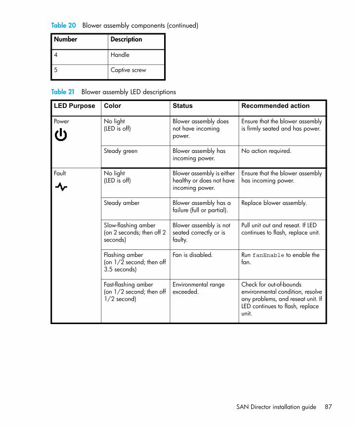
SAN Director installation guide 87
4 Handle
5 Captive screw
Table 21 Blower assembly LED descriptions
LED Purpose Color Status Recommended action
Power No light (LED is off)
Blower assembly does not have incoming power.
Ensure that the blower assembly is firmly seated and has power.
Steady green Blower assembly has incoming power.
No action required.
Fault No light (LED is off)
Blower assembly is either healthy or does not have incoming power.
Ensure that the blower assembly has incoming power.
Steady amber Blower assembly has a failure (full or partial).
Replace blower assembly.
Slow-flashing amber(on 2 seconds; then off 2 seconds)
Blower assembly is not seated correctly or is faulty.
Pull unit out and reseat. If LED continues to flash, replace unit.
Flashing amber(on 1/2 second; then off 3.5 seconds)
Fan is disabled. Run fanEnable to enable the fan.
Fast-flashing amber(on 1/2 second; then off 1/2 second)
Environmental range exceeded.
Check for out-of-bounds environmental condition, resolve any problems, and reseat unit. If LED continues to flash, replace unit.
Table 20 Blower assembly components (continued)
Number Description

Monitoring system components88
WWN cardUse the following steps to check the WWN status.
NOTE: If a Status LED on the WWN bezel flashes, the Power LED on the WWN bezel also flashes, for increased visibility.
To determine the status of the WWN card:
1. Check the LED indicators on the WWN bezel (see Figure 23 on page 90) and verify that they reflect the actual status of the components.
The WWN bezel covers the WWN card and allows its LEDs to shine through. The LEDs on the WWN bezel provide a consolidated view of the port blade status, CP card status, and power supply status. The LED patterns may temporarily change during POST and other diagnostic tests; for information about how to interpret the LED patterns, refer to Table 25 on page 91.
2. Check the WWN card status using the commands listed in Table 22 if you have problems viewing or modifying the data stored on the WWN card. Difficulty retrieving or modifying this data could indicate a WWN card failure.
3. If the error log or serial console display error messages that indicate problems with WWN units (see Table 23), the WWN card might have failed.
Table 22 Data stored on the WWN card
Data Related commands
WWN values wwn, chassisShow
Data about the chassis and WWN card chassisShow
Ethernet and fibre channel IP address information for the CP ports
ipAddrShow, ipAddrSet
History log information historyShow, historyLastShow
Names of switch switchName

SAN Director installation guide 89
WWN units correspond to information specific to the WWN card and are displayed by typing the chassisShow command.
Table 23 Messages that can indicate WWN card failure
Message type Sample error message
WWN unit fails its FRU (field replaceable unit) header access.
0x24c (fabos): Switch: switchname, error EM-I2C_TIMEOUT, 2, WWN 1 I2C timed out: state 0x4
WWN unit is being faulted. 0x24c (fabos): Switch: switchname, Critical EM-WWN_UNKNOWN, 1, Unknown WWN #2 is being faulted
WWN unit is not present or is not accessible.
0x24c (fabos): Switch: switchname, Error EM-WWN_ABSENT, 2, WWN #1 not present
Writing to the FRU history log (hilSetFruHistory) has failed.
0x24c (fabos): Switch: switchname, Error EM-HIL_FAIL, 2, HIL Error: hilSetFruHistory failed, rc=-3 for SLOT 3

Monitoring system components90
Figure 23 displays the 4/256 SAN Director WWN bezel. Table 24 identifies the components.
Figure 23 WWN bezel
Table 24 WWN bezel components
Number Description
1 Port blade power LED
2 Port blade status LED
3 CP port power LED
4 CP port status LED
5 Power supply power LED/status LED
6 Captive screw
10 pwr4
pwr3
pwr2
pwr1
987654321
1
2
3
45
625031a

SAN Director installation guide 91
Table 25 describes the WWN bezel LED patterns and the recommended actions for those patterns for the 4/256 SAN Director.
NOTE: If a Status LED on the WWN bezel flashes, the Power LED on the WWN bezel also flashes, for increased visibility.
Table 25 WWN bezel LED descriptions
LED purpose Color Status Recommended action
Port blade/CP port Power
Steady green Power is OK. No action required.
Port blade/CP port Status
Steady amber Blade is faulty. Check blade.
No light (LED is OFF) Blade is OK. No action required.
NOTE: If a blade slot or power supply bay has a filler panel installed, the corresponding LEDs on the WWN port do not light up.
Power supplyPower/Status
Steady green Power is OK. No action required.
Steady amber Power supply is faulty. Check power supply.

Monitoring system components92

SAN Director installation guide 93
4 Installing FRUsThis chapter provides the following information:
• Chassis door summary, page 94• Cable management comb and pillars summary, page 95• WWN card and bezel summary, page 100• Control processor (CP) card summary, page 110• Port blade and filler panel summary, page 124

Installing FRUs94
Chassis door summary
WARNING! The chassis door is required to ensure that these devices meet Electro Magnetic Interference (EMI) and regulatory certifications.
The 4/256 SAN Director integrates a shorter chassis door in comparison to earlier SAN Director models.
Reinstalling the chassis doorThe replacement procedure for the chassis door takes less than five minutes. See Removing the chassis door, page 40 for chassis door removal procedures. Use these steps to replace a chassis door.
1. Make sure that the levers on the spring-loaded pins on both hinges are pushed into the notches.2. Align the spring-loaded pins with the chassis portion of the hinges.3. Release the pins by pushing the levers out of the notches.
CAUTION: To avoid damaging the chassis and door, do not open the door more than 90 degrees.
Figure 24 Upper door hinge
25034a

SAN Director installation guide 95
Cable management comb and pillars summaryThis section provides instructions for replacing a cable management comb.
The cable management comb included with the 4/256 SAN Director is designed to accommodate multiple cables. Figure 25 and Table 26 identify the cable management comb components.
Figure 25 Cable management comb
Cable pillars can be used to group cables for Directors.
The replacement procedure for the cable management comb or pillar takes less than five minutes. The following items are required for the cable management comb replacement procedure:
• Cable management comb
• #2 Phillips screwdriver
CAUTION: Do not use a power screwdriver to install the cable management comb.
Table 26 Cable management comb components
Number Description
1 Ground strap connector
2 Captive screws (2 per cable management comb)
POWER SUPPLY 1 & 3
POWER SUPPLY 2 & 4
1
25032a
2

Installing FRUs96
Figure 26 shows how to remove and replace the cable management comb. Table 27 identifies the components.
Figure 26 Installing a cable management comb
Table 27 Cable management comb installation components
Number Description
1 Chassis
2 Ground strap connector
POWER SUPPLY 1
200-240 VAC 12A 50-60 Hz200-240 VAC 12A 50-60 Hz
POWER SU
PPLY 1
& 3
POWER SU
PPLY 2
& 4
POWER SUPPLY 1
!
!
POWER SUPPLY 2
!
!
POWER SUPPLY 3
!
!
POWER SUPPLY 4
!
!
!
!
FC432
FC432
7
6
5
4
3
2
1
0
15
14
13
12
11
10
9
8
56-0000590-01 Rev A
!
FC416
7
6
5
4
3
2
1
0
15
14
13
12
11
10
9
8
56-0000590-01 Rev A
!
FC416
CP4
Link
10/100 Mb/s
Active C
P
!
I O I O
I RS - 232
CP4
Link
10/100 Mb/s
Active C
P
!
I O I O
I RS - 232
!
3d
2c
1
b
0a
7d
6c
5
b
4a
11d
10c
9
b
8 a
15d
14c
13
b
12a
1
2
3
4
5
6
7
8
9
10
1
2
4 3
25035a

SAN Director installation guide 97
Figure 27 identifies the locations for the AC Power Connectors and AC Power Switches on the chassis.
If you are removing or installing the lower mounting cable management comb (shown on the left in Figure 26 on page 96) while the Director is on, you must remove the AC power connector cables one at a time in order to route the cables through the cable management comb. If only two power supplies are installed and they are both installed in slots corresponding to the same AC power connector cable, unplugging a single AC power connector cable can power down the entire chassis.
See Figure 27 for the locations of the AC power connectors and AC power switches on the chassis. Table 28 identifies the components.
Figure 27 Chassis AC power connectors and switches
3 Screws (2 per cable management comb)
4 Cable management comb
Table 28 AC power connectors and switches
Number Description
1 AC power switch (controls the power for power supplies 1 and 3)
2 AC power connector (connects to the AC power cables for power supplies1 and 3
3 AC power connector (connects to the AC power cables for power supplies2 and 4)
4 AC power switch (controls the power for power supplies 2 and 4)
Table 27 Cable management comb installation components (continued)
Number Description
200-240 VAC 12A 50-60 Hz 200-240 VAC 12A 50-60 Hz
1 2 3 425036a

Installing FRUs98
Removing a cable management combUse these steps to remove the cable management comb (shown in Figure 26 on page 96):
1. If the Director is not operating: Remove the AC power connector cables and continue with step 2, then remove the cable management comb from the chassis.If the Director is operating: Remove any cables from the comb, except the AC power connector cables.Orient comb as shown in ”Installing a cable management comb” on page 96, aligning thc holes on the comb with the holes on the chassis. Then position and tighten the two screws. The cable management comb is installed
2. Unscrew the two screws holding the comb to the chassis (see Figure 26 for location of screws) and save them for reuse.
3. With the AC power connector cables still plugged in, detach the cable management comb approximately five inches away from the chassis.
4. Switch the AC power switch off (for example, item 1 in Figure 27) and remove the corresponding AC power connector cable (for example, item 2 in Figure 27) from the chassis. Route the AC power connector cable through the comb.
5. Plug the AC power connector cable back into the connector on the chassis, and switch the AC power switch on.
6. Repeat step 4 and step 5 for the other AC power switch and AC power connector cable.7. Pull the cable management comb out and up, making sure not to loosen or remove any cables.
The cable management comb is now removed from the Director chassis.
Reinstalling a cable management combUse these steps to reinstall the cable management comb (see Figure 26 on page 96):
1. If the Director is not operating: Remove any cables and orient the comb as shown in Figure 24 on page 80, aligning the holes on the comb with the holes on the chassis. Then position and tighten the two screws. The cable management comb is installed.
If the Director is operating, go to step 2.
2. Switch the AC power switch off (for example, item 1 in Figure 27) and remove the corresponding AC power connector cable (for example, item 2 in Figure 27) from the chassis. Route the AC power connector cable through the comb.
3. Plug the AC power connector cable back into the connector on the chassis, and switch the AC power switch on.
4. Repeat step 2 and step 3 for the other AC power switch and AC power connector cable.
5. Position and tighten the two screws to secure the cable management comb to the chassis.
6. Arrange the cables through or along the cable management comb as required. Route the AC power connector cables out of each side of the chassis.

SAN Director installation guide 99
Installing the cable management pillars (optional)Use cable management pillars (shown in Figure 28) to organize the port cables into logical groups, such as according to port groups. The cable management pillars do not attach to the chassis and their use is optional.
NOTE: Cable pillars are not supported when using the FC4-32 or FC4-48 port blades because the cable count is too dense, leaving no room for the cable pillars. Instead, you should use velcro tabs to group cables for the FC4-32 or FC4-48 port blades
To use the cable management pillars, insert the cables into the holes in the guides, using a separate hole for each cable.
Figure 28 Cable management pillar
You can manage cables in a variety of ways: you may be route them down through the cable management comb or out from either side of the chassis; you may also use patch panels or cable channels on the sides of the cabinet.
To keep LEDs visible and prevent having to disconnect cables when removing neighboring cards, route fiber optic and other cables directly down, instead of across adjacent cards, or in front of the power supplies.
Leave at least one meter of slack for each fiber optic cable when you connect them. This provides room to remove and replace port blades, allows for inadvertent movement of the rack, and helps prevent the cables from being bent to less than the minimum bend radius (the minimum bend radius for a 50-micron cable is 2 inches under full tensile load and 1.2 inches with no tensile load).
Use the cable pillars provided with the SAN Director to group the cables by trunking ports (groups of four or eight neighboring ports). The cable pillars help to keep individual ports accessible by keeping the cables evenly spaced.
scale: .50" = 1"
25042a

Installing FRUs100
CAUTION: Do not not route cables in front of the air exhaust vent (located at the top front of the chassis). Do not use tie wraps for optical cables; they are easily overtightened.
WWN card and bezel summaryThe 4/256 SAN Director World Wide Name (WWN) card is highly reliable, containing fully redundant circuits; it does not usually require replacement under normal operating conditions.
Before replacing the WWN card, make sure you really need to replace it by referring to the information provided in ”How to determine whether or not to replace the WWN card” on page 102. Contact HP if you have any questions about whether the WWN card requires replacement.
The WWN card in the 4/256 SAN Director stores the following persistent information:
• Chassis serial number
• License ID (used to generate license keys)
• Two IP addresses for the control processor (CP) card slots
• Switch name, IP address, and WWN of the Core Switch or SAN Director logical switches
There are two models of the WWN bezel (see Figure 30). One model has a push card and handles. The other model attaches to the chassis using attaching screws. This section provides instructions for replacing both models of the WWN card.
The WWN card is highly reliable. Contact HP if you have any questions about whether the WWN card requires replacement. If the WWN card does fail, the Director can continue operating until a new WWN card is installed, as long as the following are true:
• The Director is running Fabric OS 5.0.1 or later.
• The configuration is not modified.
• Hardware components are not replaced.
• The Director is not rebooted.

SAN Director installation guide 101
The WWN bezel (see Figure 29 and Table 29) is located on the nonport side of the chassis and protects the WWN card. It also provides LEDs to monitor the status of the CP cards, port blades, and power supplies.
Figure 29 WWN bezel
Table 29 WWN card components
Component Description
1 Port blade power LED
2 Port blade status LED
3 CP card power LED
4 CP card status LED
5 Power supply power LED/Status LED
6 Captive screw (2 per bezel)
10 pwr4
pwr3
pwr2
pwr1
987654321
1
2
3
45
625031a

Installing FRUs102
How to determine whether or not to replace the WWN cardBefore replacing the WWN card, verify that the replacement is necessary. Any of the following events indicate that the card requires replacement:
• Status LEDs on the WWN bezel (see Figure 29 on page 101) do not reflect the actual status of the components.
• Problems viewing or modifying the data stored on the WWN card (see Table 31 on page 103).
• Error messages regarding WWN units #1 or #2 (see Table 32 on page 104)
1. To determine the status of the WWN card:LED indicators on the WWN bezel (see Figure 29 on page 101) and verify that they reflect the actual status of the components. The WWN bezel covers the WWN card and allows its LEDs to shine through. The LEDs on the WWN bezel provide a consolidated view of the port blade status, CP card status, and power supply status. Table 30 provides information about interpreting the LED patterns.
Table 30 WWN LED patterns
LED location/purpose Color Status Recommended action
Port blade/CP card power
Steady green Power is okay. No action required.
Port blade/CP card status
Steady amber Card is faulty. Check card.
No light (LED is off) Card is okay. No action required.
NOTE: If a card slot or power supply bay has a filler panel installed, the corresponding LEDs on the WWN card do not light up.
Power supplypower/status
Steady green Power is okay. No action required.
Steady amber Power supply is faulty. Check power supply.
NOTE: If a status LED on the WWN bezel flashes, the power LED on the WWN bezel also flashes, for increased visibility.

SAN Director installation guide 103
NOTE: The LED patterns might temporarily change during POST and other diagnostic tests.
2. Check the WWN card status using the commands listed in Table 31. If you have problems viewing or modifying the data stored on the WWN card. Difficulty retrieving or modifying this data may indicate a WWN card failure.
3. An error message is logged that indicates the status of the WWN unit (see Table 32).WWN units correspond to information specific to the WWN card and are displayed by the chassisShow command.
Table 31 Commands identifying the WWN card status
Type of message Sample error message
WWN values wwn, chassisShow
Data about the chassis and WWN card
chassisShow
Ethernet and FC IP address information for the CP cards
ipAddrShow, ipAddrSet
History log information historyShow, historyLastShow
Name of switch switchName

Installing FRUs104
Removing the WWN cardAllow approximately 20 minutes to remove or replace the WWN card. Obtain the following items:
• Electrostatic discharge (ESD) grounding strap
• #2 Phillips screwdriver (required only for some versions of the WWN card)
• The following is required if a serial console session is used: serial cable and a workstation computer with a terminal emulator application (such as HyperTerminal for Windows systems or TIP for Solaris systems)
This procedure requires CLI access to the Director via a telnet session or a serial console connection.
1. Open a telnet session and log into the active CP as admin. The default password is password.
NOTE: If a serial console is used, all commands must be entered through the active CP card unless otherwise indicated. For command details, refer to the Fabric OS command reference manual.
Table 32 WWN card related system log messages
Type of message System message (errshow or errdump)
WWN unit removal was detected
<timestamp>, [EM-1050], <sequence-number>,, INFO, <system-name>, FRU WWN # removal detected.
WWN unit insertion was detected
<timestamp>, [EM-1049], <sequence-number>,, INFO, <system-name>, FRU WWN # insertion detected.
WWN unit fails to power on
<timestamp>, [EM-1004], <sequence-number>,, CRITICAL, <system-name>, WWN # failed to power on
WWN unit is being faulted
<timestamp>, [EM-1034], <sequence-number>,, ERROR, <system-name>, WWN # set to faulty, rc=<return code>

SAN Director installation guide 105
CAUTION: Do not power cycle or reboot the Director or replace the CP cards or port cards until the WWN card is verified as functional or a replacement WWN is installed. If any of these events happen while the WWN card is failed or removed, the configuration information is lost, and it will be necessary to reconfigure the Director after installing the new WWN card.
Disassembling any part of the WWN card voids the part warranty and regulatory certifications. The WWN contains no serviceable parts.
2. Verify that you are logged into the active CP. Run the haShow command to determine the active CP.
3. Type fruReplace wwn from the active CP card and wait for the message Do you wish to continue [y/n]? to display; then enter y.
4. Wait until the WWN card data is backed up. Do not type continue until the mechanical replacement is complete (see ”Installing a WWN card” on page 108).
5. Wait until all the LEDs on the WWN bezel turn off.6. Unscrew both captive screws on the WWN bezel (see Figure 29); then, pull the bezel away
from chassis and set it aside. The WWN card is visible.
CAUTION: To protect the WWN card components, wear an ESD grounding strap and prepare an antistatic bag or grounding pad on which to place the WWN card. Do not place anything on top of the card.
switch:admin> frureplace wwnThis is the WWN card hot swap interface.Continuing from this point will requirethe whole process to be completed.If this process is not complete due to apower cycle, or CP failover, please followthe recovery procedure inCore Switch WWN Card Removal andReplacement document.Do you wish to continue [y/n]?
Backing up WWN card data, please wait about 25 seconds for further instruction.Please install the new FRU now.
If this session lost for any reason, please re-enter the frureplace command andfollow the instructions to complete the operation.
Please enter the word `continue' after the new WWN card has been installed:

Installing FRUs106
7. Remove the WWN card as follows:• To remove a WWN card that has handles: Use the handles to gently pull the card away
from the chassis.• To remove a WWN card that does not have handles: Using the Phillips screwdriver, unscrew
the two attaching screws which secure the WWN card to the chassis. Holding the card by the edges, gently pull the card away from the chassis.
8. Set the WWN card on a static-free surface, such as a grounding pad.a. The message Please enter the word ‘continue’... is displayed in the CLI. Do not
enter continue until the mechanical replacement is complete (see ”Installing a WWN card” on page 108).
b. All the LEDs on the WWN bezel turn off.
9. Unscrew both captive screws on the WWN bezel (see Figure 30 on page 107); then, pull the bezel away from chassis and set it aside. The WWN card is visible.
CAUTION: To protect the WWN card components, wear an ESD grounding strap and prepare an antistatic bag on which to place the WWN card. Do not place anything on top of the card.
10.Remove the WWN card, see Figure 30 and Table 33:
• To remove a WWN card with handles: Use the handles to gently remove the card.
• To remove a WWN card without handles: Use the Phillips screwdriver to unscrew the two attaching screws that secure the WWN card to the chassis. Holding the card by the edges, gently pull the card away from the chassis.
Set the WWN card on a static-free surface, such as a grounding pad.
switch:admin> frureplace wwnThis is the WWN card hot swap interface.Continuing from this point will require the whole process to be completed.If this process is not complete due to a power cycle, or CP failover, please follow the recovery procedure in Core Switch WWN Card Removal and Replacement document.
Do you wish to continue [y/n]? y
Backing up WWN card data, please wait about 25 seconds for further instruction.Please install the new FRU now.
If this session lost for any reason, please re-enter the frureplace command andfollow the instructions to complete the operation.
Please enter the word `continue' after the new WWN card has been installed:

SAN Director installation guide 107
Figure 30 shows the removal and installation of a WWN card, as described in the WWN bezel and card replacement procedures. Table 33 identifies the components.
Figure 30 Removing and replacing the WWN card
Table 33 WWN card components
Item Description
1 Attaching screws
2 WWN without push pad
1
2
3
4
5
6
7
8
9
10
PULL
PULL
PUSH
10
pwr4
pwr3
pwr2
pwr1
98
76
54
32
1
Alternate WWN Card
1
2
3
45
6
7
8
25

Installing FRUs108
Installing a WWN cardUse these steps to install a new WWN card. See Figure 30 and Table 33.
1. Unpack the new WWN card and save the packaging for returning the faulty WWN card.
2. Install the WWN card:
• To install a WWN card that has handles: Hold the card by the handles and orient with the LEDs at the top (see Figure 30 on page 107); then, align the connector on the card with the connector on the chassis (the connectors are keyed to ensure correct installation) and use the push pad to press the card onto the connector gently, until it is fully seated.
• To install a WWN card that does not have handles: Hold the card by the edges, press the card onto the connector gently, until it is fully seated. Use the Phillips screwdriver to screw the WWN card into the chassis with the two attaching screws.
The WWN card retains slight freedom of movement after installation.
CAUTION: Do not force the installation; if the card does not install easily, make sure it is correctly oriented.
3 Bezel
4 Handle
5 WWN card with push pad
6 WWN connector
7 Push pad
8 Captive screw (two per bezel)
Table 33 WWN card components
Item Description

SAN Director installation guide 109
3. Reinstall the WWN bezel:
a. Orient the bezel on the chassis (see Figure 30 on page 107), insert both retaining screws into the standoffs on the chassis, and tighten to finger-tight.
NOTE: If a serial console session is active, several removal detected and insertion detected messages are displayed on the console as a result of the replacement.
b. In the CLI session, enter continue to indicate that the replacement has been completed:
4. Verify that the WWN card is correctly connected by observing the LEDs on the WWN card to determine if they reflect the status of the components.
NOTE: The LEDs might take up to 2 minutes to begin functioning after WWN card installation.
5. Pack the faulty WWN card in the packaging provided with the new card and return it to HP.
Please enter the word `continue' after the new WWN card has been installed: continue
Restoring the information to the replacement FRU now, please wait about 20 seconds to complete
Verifying the replacement FRU now...
WWN card hot swap is now complete.
FRU replacement completed successfully!

Installing FRUs110
Control processor (CP) card summaryThis section provides instructions for replacing a CP card (also known as CP4).
The 4/256 SAN Director CP card integrates the following characteristics:
• Two CP cards: one located in slot 5 and the other in slot 6.
• The configuration on the active CP card is mirrored to the standby CP card; this section includes steps to ensure that the new CP card boots up as the standby CP card.
• The new CP card assumes the IP address and host name assigned to the slot.
• If the new CP card does not have the same firmware as the active CP card, it must be upgraded or downgraded to the same firmware version.
• The logical switches in the SAN Director can continue to operate while a CP card is replaced if the other CP card continues to operate and no failover occurs.
How to determine whether or not to replace a CP cardIf you have not already done so, confirm that you need to replace the CP card before continuing. The following events might indicate that a CP card is faulty:
• The status LED on the CP card is lit amber, or the power LED is not lit.
• The CP card does not respond to telnet commands, or the serial console is not available.
• The slotShow command does not show that the CP card is enabled.
• The haShow command indicates an error.• The haShow command indicates that the CP cards have not achieved redundancy (after 30
minutes).
• The calendar clock is inaccurate, or the CP card does not boot up or shut down normally.
• Any of the following messages display in the error log:
• Slot unknown, which refers to a CP slot
• CP card errors or I2C timeouts
• FRU: FRU_FAULTY messages for a CP card
• Configuration loader messages or Sys PCI config messages
• Generic system driver messages (FABSYS)
• Platform system driver messages (Platform)
• EM messages that indicate a problem with a CP card

SAN Director installation guide 111
• Function fail messages for the CP master
For complete information about diagnostic and error messages, refer to the Fabric OS system error messages reference manual.
Time and items required for CP card replacementThe replacement procedure for the CP card takes approximately 30 minutes. Obtain the following items:
• ESD (electrostatic discharge) grounding strap
• Workstation computer
• Serial cable
• IP address of an FTP server to back up the Director configuration
• Phillips #2 screwdriver
• CP card for the 4/256 SAN Director
Record critical switch informationBack up the switch configuration before you replace a CP card. Refer to the HP StorageWorks Fabric OS administrator guide for backup information.
To record critical switch information:
1. Login to the healthy CP card as admin, using either a telnet or a serial console connection.2. Type haShow to determine which CP card is active.
swDir:admin> haShowLocal CP (Slot 6, CP1) : ActiveRemote CP (Slot 5, CP0) : Standby, HealthyHA Enabled, Heartbeat Up, HA State Synchronized

Installing FRUs112
NOTE: Enter all remaining commands from the serial console for the active CP card, unless otherwise indicated. For more information about commands, see the Fabric OS command reference manual.
3. If the healthy CP card is acting as the active CP card, go to step 6. If the faulty CP card is performing as the active CP card, fail over the cards as described here:
a. Login to the faulty CP card as admin, using either a telnet or a serial console connection.
If you connect successfully to the faulty CP continue to step b.If you cannot connect to the faulty CP, then you can remove the faulty CP card for repair asfollows:• Turn the CP card off and notify the Director of a hot swap request by sliding the slider
switch in the top ejector down to the off position.• Then, wait until the active CP LED on the healthy CP card is lit. You can remove the CP for
repair.b. Type haFailover. The healthy CP card becomes the active CP card.
c. Wait until the status LED on the healthy CP card is no longer lit (indicates failover is complete).
d. Type haShow from the healthy CP card (the new active CP card) to verify the failover.

SAN Director installation guide 113
Following is an example of failing over a CP card in a 4/256 SAN Director:
4. Type firmwareShow to record the firmware version of the active CP card.5. Type haDisable from the active CP card to prevent failover or communication between the CP
cards during the replacement.6. Logged into the active CP, use the configUpload command to upload the switch configuration
to a specified FTP server. Enter the requested information at the prompts.Following is a sample of backing up the configuration files on the Director:
Fabric OS (cp1)
cp1 login: adminPassword:swDir:admin> hashowLocal CP (Slot 6, CP1): ActiveRemote CP (Slot 5, CP0): Standby, HealthyHA enabled, Heartbeat Up, HA State synchronized
swDir:admin> hafailoverLocal CP (Slot 6, CP1): ActiveRemote CP (Slot 5, CP0): Standby, HealthyHA enabled, Heartbeat Up, HA State synchronized
Warning: This command is being run on a redundant controlprocessor(CP) system. If the above status does not indicate'HA State synchronized', then the CPs are not synchronizedand this operation will cause the active CP to reset. Thiswill cause disruption to devices attached to both switch 0and switch 1 and will require that existing telnet sessionsbe restarted. To reboot a single logical switch on thissystem, use the switchreboot command while logged in tothat logical switch.
Are you sure you want to fail over to the standby CP [y/n]?
swDir:admin> haShowLocal CP (Slot 6, CP1) : Standby, HealthyRemote CP (Slot 5, CP0) : ActiveHA Enabled, Heartbeat Up, HA State Synchronized
swDir:admin> configUploadProtocol (scp or ftp) [ftp]: ftpServer Name or IP Address [host]: 123.456.78.90User Name [None]: userFile Name [config.txt]: config.txtPassword: xxxxxxxxupload complete

Installing FRUs114
Removing a CP cardThe 4/256 SAN Director continues to operate while a CP card is being replaced if the redundant CP card is active and a failover does not occur (you can prevent failover by issuing the haDisable command).
CAUTION: The core section within the 4/256 SAN Director CP cards provides internal routing bandwidth that is always active on both CP cards. Removing a CP card might impact user performance and should not occur until the replacement CP card is ready to be installed.
WARNING! Do not replace the real time clock battery on a CP card. There is danger of explosion if the battery is incorrectly replaced or discarded. Contact HP Technical Support if the real time clock begins to lose time.
To remove a CP card:
1. Login to the active CP as admin.2. You can use a serial cable or if you have connected the Director to your IP network, you can use
telnet, Web Tools, or Fabric Manger. You can determine which CP is active using the haShow command or view the active LED on the front of the CP.
3. If the CP you want to replace is the active CP issue the haFailover command. Wait until the failover has completed. Use the haShow command to verify the CPs are synchronized and the failover is complete.
4. Use the slider to power off the blade, and wait until the standby CP power LED is off.5. Disconnect all cables (modem, serial, Ethernet) from the standby CP.6. Unscrew the thumb screw from both ejectors using the Phillips screw driver.7. Lever open both ejector handles simultaneously to approximately 45 degrees and pull the CP
card out of the chassis (see Figure 31 on page 115).

SAN Director installation guide 115
Figure 31 shows how to remove a CP card from the chassis. Table 34 identifies the components.
Figure 31 Removing a CP card
Table 34 CP card removal
Component Description
1 4/256 SAN Director chassis door
2 On/Off slider switch (in the Off position)
3 Ejector
POWER SUPPLY 1
200-240 VAC 12A 50-60 Hz200-240 VAC 12A 50-60 Hz
POWER SUPPLY 1
!
!
POWER SUPPLY 2
!
!
POWER SUPPLY 3
!
!
POWER SUPPLY 4
!
!
!
!
FC432
FC432
7
6
5
4
3
2
1
0
15
14
13
12
11
10
9
8
56-0000590-01 Rev A
!
FC416
7
6
5
4
3
2
1
0
15
14
13
12
11
10
9
8
56-0000590-01 Rev A
!
FC416
CP4
Link
10/100 Mb/s
Active C
P
!
I O I O
I RS - 232
7
6
5
4
3
2
1
0
15
14
13
12
11
10
9
8
56-0000590-01 Rev A
!
FC416
1
2
3
4
5
6
7
8
9
10
scale:.13865" = 1"
CP4
Link
10/100 Mb/s
Active C
P
!
I O I O
I RS - 232
1
2
3

Installing FRUs116
Installing a new CP card
CAUTION: Do not force the installation. If the CP card does not slide in easily, ensure that it is correctly oriented and aligned in the card guides before continuing.
To ensure proper cooling, do not route cables in front of the exhaust vent located at the top on the port side of the chassis.
WARNING! Use the same version of Fabric OS on both CP cards. Using different versions is not supported and might cause a malfunction. If the replacement CP card has a different version of Fabric OS, bring both cards to the same firmware version.
Use these steps to install a new CP card in the empty card slot (#5 or #6). See Figure 31 on page 115.
1. Open the ejector handles to approximately 45 degrees; then, orient the CP card so that the handles are toward you and the flat metal side is on your left.
2. Align the flat metal side of the CP card inside the lower and upper card guides in the slot; then, slide the CP card into the slot until it is firmly seated.
3. For the 4/256 SAN Director CP card, tighten the thumb screw inside each handle using the Phillips screwdriver.
4. Turn the CP card on by sliding the ON/OFF switch in the top handle up, to cover the thumb screw. For CP1 cards, no action is required. Go to step 5.
5. Verify that the power LED is green (wait a few seconds). If not, make sure the CP card has power and is firmly seated and that the ejectors are in the locked position.
6. Connect the modem, serial, and Ethernet cables, as required, to the new CP card.
The new CP card assumes the IP address and host name assigned to the slot.
7. Verify the installation (see ”Verifying operation of the new CP card” next).

SAN Director installation guide 117
Verifying operation of the new CP cardTo verify that boot and POST are complete on the new CP card (requires a minimum of three minutes), and that the CP cards have achieved failover redundancy:
1. Wait until the status LEDs on both CP cards are not lit.
NOTE: The status LEDs on the active CP card lights amber until the active CP card is fully operational; the status LED on the standby CP card lights amber until the CP cards have achieved failover redundancy.
2. Login into the active CP card as admin.
3. Enable the redundancy feature by issuing the haEnable command from the serial console for the active CP card.
4. From the serial console for the active CP card (it should still be the CP card that was not replaced), issue the haShow command, and verify that the command output shows:
• HA Enabled Heartbeat Up
• HA-state in sync.If not, POST is not complete or the CP cards have not yet achieved redundancy. Wait one or two minutes and re-enter the command, until you can verify that redundancy has been achieved.
NOTE: If haShow indicates any errors after redundancy is achieved, contact HP.

Installing FRUs118
5. Type slotShow. The command output shows the new CP card as ENABLED:
6. Type firmwareShow to determine the firmware version.
The following example shows sample output for the firmwareShow command:
7. If the firmware version on the replacement card does not match that on the active CP card, bring the replacement card to the same firmware level as the active card. Check with the HP web site for supported versions.
swDir:admin> slotShow
Slot card Type ID Status
---------------------------------
1 SW card 17 ENABLED
2 SW card 17 ENABLED
3 SW card 17 ENABLED
4 SW card 17 ENABLED
5 CP card 16 ENABLED
6 CP card 16 ENABLED
7 SW card 17 ENABLED
8 SW card 17 ENABLED
9 SW card 17 ENABLED
10 SW card 17 ENABLED
swDir:admin>
swDir:admin> firmwareShowLocal CP (Slot 6, CP1): Active Primary partition: v5.2.0 Secondary Partition: v5.2.0Remote CP (Slot 5, CP0): Standby Primary partition: v5.2.0 Secondary Partition: v5.2.0
Note: If Local CP and Remote CP have different versionsof firmware, please retry firmwaredownload command.
swDir:admin>

SAN Director installation guide 119
8. Type firmwareDownload -s to download the firmware to only one of the CP cards. Enter all requested information (use default values):
9. Type firmwareDownloadStatus to verify that the firmware downloaded successfully.
10.Type haEnable command to reenable HA on the active CP card.
11. Type reboot.
12. Verify that the reboot is complete and the CP cards have achieved failover redundancy:
a. Wait until the status LEDs on both CP cards are not lit.
b. Type haShow and verify that the command output includes HA Enabled Heartbeat Up. If not, wait a minute and re-enter the command, until you have verified that redundancy is achieved.
13. Type firmwareShow to verify that the firmware version is dated.
14. Pack the old CP card in the packaging provided with the new CP card, and contact HP to determine the return procedure.
swDir:admin> firmwaredownload -sServer Name or IP Address: 192.168.100.1User Name: userFile Name: /software/v5.2.0/release.plistPassword: ********Do Auto-Commit after Reboot [Y]: Reboot system after download [N]: Firmwaredownload has started.2005/03/07-14:59:21, [SULB-1001], 923,, WARNING, SilkWorm 48000, Firmwaredownload command has started.Start to install packages......dir ##################################################ldconfig ##################################################glibc ##################################################bash ##################################################readline ##################################################terminfo ##################################################termcap ##################################################setup ##################################################
<output truncated>
tz ##################################################mtracer-tool ##################################################lkcd ##################################################sysstat ##################################################Removing unneeded files, please wait ...Finished removing unneeded files.
All packages have been downloaded successfully.Firmwaredownload has completed successfully.2005/03/07-15:05:56, [SULB-1002], 924,, INFO, SilkWorm 48000, Firmwaredownload command has completed successfully.

Installing FRUs120
Power supply summaryThe SAN Director can continue operating during the replacement if at least one power supply continues operating. A minimum of two power supplies are recommended.
WARNING! When one or more Intelligent blades are present in the chassis, like the HP StorageWorks B-Series MP Router Blade, four power supplies are required (two plus two redundant) for proper operation.
NOTE: You do not need to notify the SAN Director of a hot-swap request for a power supply. The power supply bays are isolated; power supply filler panels are not required to ensure correct air flow.
The power supply unit slots are numbered 1 through 4 from bottom to top when facing the port side of the chassis. The AC power connector on the left provides power to the power supplies in slots 1 and 3; the AC power connector on the right provides power to the power supplies in slots 2 and 4 (see Figure 32 on page 121).
The AC power connectors and the power supply slots are color-coded to identify which AC power connectors provide power to which power supply slots. Power supply unit labels for slots 1 and 3 and the corresponding AC power connector label are violet, and power supply unit labels for slots 2 and 4 and the corresponding AC power connector label are yellow.
For information about how to check the status of hardware components using Fabric OS commands, see the HP StorageWorks Fabric OS administrator guide.
CAUTION: To protect against AC failure, HP recommends a minimum of one power supply in slot 1 or 3 and one in slot 2 or 4, for a total of two. Additional power supplies might be required depending on how many blades are installed.
If only two power supplies are installed and they are both installed in slots corresponding to the same AC power connector cable, unplugging a single AC power connector cable powers down the entire chassis.
Disassembling any part of the power supply voids the part warranty and regulatory certifications. There are no user-serviceable parts inside the power supply.
To protect against AC failure, HP recommends a minimum of one power supply in slot 1 or 3 and one in slot 2 or 4, for a total of two. Additional power supplies might be required depending on the type of blades installed.

SAN Director installation guide 121
Replacing a power supply and filler panelThe replacement procedure for each power supply takes less than 5 minutes. A power supply unit or filler panel is required for the power supply replacement procedure Figure 32 illustrates the removal and installation of a power supply or filler panel, as described in the replacement procedures.
Figure 32: Installing and removing the filler panel or power supply
Table 35 Power Supply components
Component Description
1 Power supply
2 Locking tab
POWER SUPPLY 1
200-240 VAC 12A 50-60 Hz200-240 VAC 12A 50-60 Hz
POWER SUPPLY 1
POWER SUPPLY 2
!
!
POWER SUPPLY 3
POWER SUPPLY 4
!
!
!
!
FC4
32FC4
32
7
6
5
4
3
2
1
0
15
14
13
12
11
10
9
8
56-0000590-01 Rev A
!
FC4
16
7
6
5
4
3
2
1
0
15
14
13
12
11
10
9
8
56-0000590-01 Rev A
!
FC4
16
CP4
Link
10/100 Mb/s
Active C
P
!
I O I O
I RS - 232
CP4
Link
10/100 Mb/s
Active C
P
!
I O I O
I RS - 232
7
6
5
4
3
2
1
0
15
14
13
12
11
10
9
8
56-0000590-01 Rev A
!
FC4
16
1
2
3
4
5
6
7
8
9
10
!
!
1
3
4
5
6
7
2

Installing FRUs122
Locating AC power inlets on the SAN DirectorFigure 33 and Table 36 identify the locations of the AC power connectors and AC power switches on the SAN Director chassis. In order for the power supply units to function correctly, the AC power connector cables must be plugged in to the AC power connectors and the AC power switches must be turned on.
Figure 33 Chassis AC power connectors and switches
Table 36 AC power connectors and switches
3 Handle (displayed in an unlocked position)
4 Filler panel
5 Lip
6 AC power connector label (2 per chassis)
7 Power Supply unit label (4 per chassis)
Table 35 Power Supply components (continued)
Component Description
Number Description
1 AC power switch (controls the power for Power Supplies 1 and 3)
2 AC power connector (connects to the AC power cables for Power Supplies 1 and 3
3 AC power connector (connects to the AC power cables for Power Supplies 2 and 4)
4 AC power switch (controls the power for Power Supplies 2 and 4)
200-240 VAC 12A 50-60 Hz 200-240 VAC 12A 50-60 Hz
1 2 3 425036a

SAN Director installation guide 123
Removing a power supplyUse these steps to remove a power supply. Figure 32 and Table 35 identify power supply components.
1. If the SAN Director is not operating during the replacement procedure, skip to step 2.If the SAN Director is going to continue operating during the replacement procedure, check the power LEDs to verify that the minimum number of power supply units required is still functioning. A fully populated 4/256 SAN Director requires a minimum of one power supply in any slot at all times to ensure power. For maximum availability of the Director, you should have a minimum of one power supply unit in slot 1 or 3, and one in slot 2 or 4.
2. Push the locking tab toward the power supply unit, and pull the handle out and down. See Figure 32.
NOTE: Support the power supply unit from underneath while removing it from the chassis.
3. Use the handle to pull the power supply out of the chassis. See Figure 32.4. If you are not replacing the power supply unit, orient the filler panel so the handle is vertical and
the side tabs are on the right; then, push the filler panel into the slot.
Reinstalling a power supplyUse these steps to install a power supply.
NOTE: Do not force the installation of the power supply unit or filler panel. If the unit does not install easily, verify that it is properly oriented.
Ensure that the handle is unlocked; otherwise, damage might occur to the power supply unit and chassis during the installation.
1. If a filler panel covers the slot, pull it out by the handle. See Figure 32.2. Orient the power supply unit with the handle toward the front of the chassis and the LEDs on the
left.3. Unlock the handle by pressing the locking tab.4. Insert the unlocked power supply unit completely into the slot and push the handle up until it
clicks.5. Verify that the power supply unit is seated by pulling gently on the handle.6. Verify that the power LED on the power supply unit displays a steady green light.7. If it does not, ensure that both AC power connector cables are plugged in and both AC power
switches are flipped to 1 (AC switch lights up green).

Installing FRUs124
Port blade and filler panel summaryThis section provides instructions for replacing port blades and filler panels. This section also provides recommendations for cable management.
A filler panel should be removed only when it is to be replaced with a port blade or new filler panel, (see Figure 35). Any slot that is not occupied by a port blade should be occupied by a filler panel to ensure correct cooling of the chassis and protection from dust. Slots are numbered from one through ten, from left to right, when facing the port side.
CAUTION: Wear a grounded ESD strap when handling a port blade. Use the grounding connections above the power connectors on the chassis.
Do not force the port blade installation. If the port blade does not slide in easily, make sure it is correctly aligned inside the rail guides before continuing. Installing a port blade with incorrect alignment damages both the chassis and the replacement part.
Hold the port blade by the edges of the metal pan. Do not use the ejectors to hold a port blade.
Disassembling any part of a port blade voids the part warranty and regulatory certifications. There are no user-serviceable parts in the port blade.
Replacing a port bladeThe replacement procedure for each port blade or filler panel takes less than 10 minutes. Obtain the following items:
• ESD (electrostatic discharge) grounding strap
• Workstation computer
• Replacement port blade or filler panel
• Phillips screwdriver
• Small form-factor pluggable (SFP) transceivers, as needed
• Optical cables, as needed

SAN Director installation guide 125
NOTE: Some optional port blades differ slightly in design. Follow the instructions that pertain to your specific port blade model.
To remove an existing port blade:
1. Check the power LED, status LED, port speed LED, and port status LED to determine any possible problems with the current port blade.
A failed port blade can be identified by inspecting the LEDs on the front panel of each port blade (see Figure 15 on page 70 and Figure 16 on page 72). The WWN bezel on the nonport side of the Director also displays a power and status LED for each port blade.
2. Before replacing a port blade, establish a telnet or console connection to determine a failure and verify operation after replacement. Refer to the HP StorageWorks Fabric OS administrator guide for information about checking the status of hardware components using the CLI.
3. Check for adequate cable slack.
Make sure there is plenty of cable slack to remove a port blade without optical, power, or Ethernet cable obstruction. See ”Recommendations for cable management” on page 95 for cabling guidelines.
4. Verify that you have the proper spare part (filler panel or replacement port blade).
Make sure that the part number on the unit being replaced matches the replacement part number. The chassisShow command displays information about the port blades, including part numbers, serial numbers, and additional status.
5. Verify that traffic is not flowing through the port blade (port speed LEDs and port status LEDs should be off) before disconnecting cables.
NOTE: Before removing any cables from a faulty port blade, make a note of cable order (identify each cable via its physical port). This reduces confusion during recabling. If multiple port blades are being replaced, replace one card at a time to prevent confusion during cable reconnection. Before replacing a port blade, determine whether it is the entire card or only the SFPs that are faulty.
6. Disconnect all cables and SFP transceivers from the port blade.
7. For the FC2-16, FC4-16, FC4-32 and FC4-16IP port blades: Turn the port blade off by sliding the slider switch in the top ejector down, to the off position (see Figure 34 and Table 37). This initiates a hot-swap request.
For the FC4-48 port blade: Adjust the ejectors to the open position. Unscrew the two thumb screws from the top and bottom ejectors on the port blade using the Phillips screwdriver. Unscrew the top thumb screw until it pops out.

Installing FRUs126
8. Wait for the power LED to turn off in response to the hot-swap request (step 7) before uninstalling the port blade.
Figure 34 Removing a port blade with sliders
9. For the FC4-48 port blade: Go to step 10.
For the FC2-16, FC4-16, FC4-32 and FC4-16IP port blades: Unscrew the two thumb screws from the top and bottom ejectors on the port blade using the Phillips screwdriver.
Table 37 Port blade replacement
Component Description
1 Director chassis
2 4Gb Port blade
3 On/Off slider switch (in the Off position)
4 Ejector
POWER SUPPLY
1
200-240 VAC 12A 50-60 Hz
200-240 VAC 12A 50-60 Hz
POWER SUPPLY
1
!
!
POWER SUPPLY
2
!
!
POWER SUPPLY
3
!
!
POWER SUPPLY
4
!
!
!
!
FC432
FC432
7
6
5
4
3
2
1
0
15
14
13
12
11
10
9
8
56-0000590-01 Rev A
!
FC416
CP4
Link
10/100 Mb/s
Active CP
!
I O I O
I RS - 232
CP4
Link
10/100 Mb/s
Active CP
!
I O I O
I RS - 232
7
6
5
4
3
2
1
0
15
14
13
12
11
10
9
8
56-0000590-01 Rev A
!
FC416
1
2
3
4
5
6
7
8
9
10
7
6
5
4
3
2
1
0
15
14
13
12
11
10
9
8
56-0000590-01 Rev A
!
FC416
3
1
2
4
25217a

SAN Director installation guide 127
10.For the FC2-16, FC4-16, FC4-32 and FC4-16IP port blades: Lever both ejectors open simultaneously to approximately 45 degrees and pull the port blade out of the chassis.
For the FC4-48 port blade: Open the ejectors. Pull the port blade out of the chassis using the ejectors.If the port blade is not being replaced by another HP StorageWorks port blade, install a filler panel to ensure correct cooling of the chassis and protection from dust. See ”Removing and replacing port blade filler panels” on page 128 for instructions.
Installing a port bladeUse these steps to install a port blade.
CAUTION: Make sure to gently apply pressure to the port blade, in order to properly seat the blade all the way into the slot. Applying excessive pressure may damage the VHDM connectors on the Director’s backplane.
B
1. If a port blade filler panel is installed in the slot, you must remove it. See ”Removing port blade filler panels” on page 129.
2. Orient the port blade so that the ports are at the front of the chassis and the flat side of the port blade is on the left.
3. Open the ejectors to approximately 45 degrees, align the flat side of the port blade inside the upper and lower rail guides in the slot (see ”Removing a port blade with sliders” on page 126), and slide the port blade into the slot, with slight pressure to the left, until it is firmly seated.
4. Close the ejectors by pushing the handles toward the center of the port blade until the ejectors lock. The levering action of the handles seats the port blade in the slot.
5. For the FC2-16, FC4-16, FC4-32 port blades, tighten the thumb screw inside each handle using the Phillips screwdriver.
6. For the FC2-16, FC4-16, FC4-32 port blades, turn the port blade on by sliding the slider switch in the top ejector up, covering the thumb screw.
7. Verify that the power LED on the port blade displays a steady green light (it might require a few seconds to turn on). If it does not turn on, ensure that the port blade is firmly seated.
NOTE: The LED patterns might temporarily change during POST and other diagnostic tests.
8. Install SFP transceivers and cables in the port blade, as required.
9. Group and route the cables as desired (see ”More tips on managing cables” on page 129).

Installing FRUs128
Identifying port blade filler panel typesRemove the filler panel, if installed. There are three filler panel types (filler panel with handle, filler panel with ejectors and filler panel with pull tabs). See Figure 35 and Table 38:
Figure 35 Identifying port blade filler panel types
Table 38 Port blade filler panel components
Component Description
1 Filler panel with handle
2 Captive screw (2)
3 Handle
4 Filler panel with ejectors
5 Ejectors (2)
6 Pull tabs (2)
7 Filler panel with pull tabs
POWER SUPPLY
1
200-240 VAC 12A 50-60 Hz
200-240 VAC 12A 50-60 Hz
POWER SUPPLY
1
!
!
POWER SUPPLY
2
!
!
POWER SUPPLY
3
POWER SUPPLY
4
!
!
7
6
5
4
3
2
1
0
15
14
13
12
11
10
9
8
56-0000590-01 Rev A
!
FC416
CP4
Link
10/100 Mb/s
Active CP
!
I O I O
I RS - 232
CP4
Link
10/100 Mb/s
Active CP
!
I O I O
I RS - 232
7
6
5
4
3
2
1
0
15
14
13
12
11
10
9
8
56-0000590-01 Rev A
!
FC416
1
2
3
4
5
6
7
8
9
10
7
65
4
3
21
25043a

SAN Director installation guide 129
Removing port blade filler panelsBefore starting this procedure, see ”Identifying port blade filler panel types” on page 128 to determine your specific filler panel type.
1. To remove a filler panel with a handle:
a. Unscrew the two captive screws securing the filler panel.b. Grasp the handle in the middle of the filler panel faceplate and remove.
2. To remove a filler panel with ejectors:a. Push in the yellow tab on each ejector.b. Lever both ejectors all the way open, and remove the filler panel from the chassis.
3. To remove a filler panel with pull tabs:a. Unscrew the top and bottom captive screws on the filler panel.
b. Pull on the top and bottom pulling tabs to slide the filler panel out of the chassis.
Replacing port blade filler panelsBefore starting this procedure, see ”Identifying port blade filler panel types” on page 128 to determine your specific filler panel type
1. To install a filler panel with a handle:a. Align the flat side of the filler panel inside the upper and lower rail guides in the slot.b. Slide the filler panel into the slot (with slight pressure to the left) until it is firmly seated.c. Tighten the two captive screws using the Phillips screw driver.
2. To install a filler panel with ejector handles:a. Orient the filler panel so that the ejectors are at the front of the chassis and the flat side of the
filler panel is on the left.b. Open the ejectors to approximately 45 degrees, align the flat side of the filler panel inside
the upper and lower rail guides in the slot, and slide the filler panel into the slot, with slight pressure to the left, until it is firmly seated.
c. Close the ejectors by pushing the black handles toward the center of the filler panel until the ejectors lock (slight audible click). The levering action of the handles seats the filler panel in the slot.
3. To install a filler panel with pull tabs:a. Orient the filler panel so that the captive screws are at the front of the chassis and the flat
side of the filler panel is on the left.b. Screw the captive screws in place, securin the filler panel to the chassis.
More tips on managing cablesYou can manage cables in a variety of ways, such as routed down through the cable management comb or routed out either side of the chassis, and by using patch panels or cable channels on the sides of the cabinet.

Installing FRUs130
To keep LEDs visible and prevent having to disconnect cables when removing neighboring cards, route fiber optic and other cables directly down, instead of across adjacent cards or in front of the power supplies.
Leave at least one meter of slack for each fiber optic cable when you connect them. This provides room to remove and replace the port blade, allows for inadvertent movement of the rack, and helps prevent the cables from being bent to less than the minimum bend radius (the minimum bend radius for a 50-micron cable is 2 inches under full tensile load and 1.2 inches with no tensile load).
Use the cable pillars provided to group the cables by trunking ports (groups of four or eight neighboring ports). The cable pillars help to keep individual ports accessible by keeping the cables evenly spaced; they also help to provide clearance for removing a neighboring card. Cable pillars are not supported when using the FC32 port blades because the cable count is too dense, leaving no room for the cable pillars. Use velcro tabs to group cables for the FC4-32 port blades.
CAUTION: Do not route the cables in front of the air exhaust vent (located at the top of the front of the chassis). Do not use tie wraps for optical cables; they are easily overtightened.
B
Replacing a blower assemblyThis procedure provides instructions for replacing a 4/256 SAN Director blower assembly. The 4/256 SAN Director requires a minimum of two operating blower assemblies at all times. To ensure continuous adequate cooling, maintain three operating blower assemblies at all times except for the brief period when replacing a blower assembly. The port blades automatically shut down if the internal temperature range is exceeded (up to 75º Celsius).
CAUTION: If more than one blower must be turned off at the same time, the 4/256 SAN Director should be turned off to prevent overheating.
B
NOTE: Disassembling any part of the blower assembly voids the part warranty and regulatory certifications. There are no user-serviceable parts inside the blower assembly.

SAN Director installation guide 131
Figure 36 illustrates the removal and installation of a blower assembly, as described in the Blower Assembly replacement procedures. Table 39 identifies the components.
Figure 36 Removing and installing the Blower Assembly
Table 39 Blower assembly components
Item Component
1 4/256 SAN Director chassis
2 Blower Assembly
3 Captive screws (two per blower assembly unit)
10pwr4
pwr3
pwr2
pwr1
98
76
54
32
1
1
25044a
32

Installing FRUs132
Time and items required for replacing a blower assemblyThe replacement procedure for each blower assembly takes less than 5 minutes.
The following items are required for the blower assembly replacement procedure:
• Replacement blower assembly• Phillips #2 screwdriver
Removing a faulty blower assembly
CAUTION: Support the blower assembly from underneath while removing or inserting it from the chassis.
B
To remove a blower assembly:
1. Before removing one blower assembly, verify that the other two blower assemblies are functioning correctly. The power LEDs should be steady green and the attention/fault LEDs should not be lit.For information about how to check the status of hardware components using the command line interface, refer to the HP StorageWorks Fabric OS administrator guide.
2. Use the screwdriver to loosen the captive screws at the top and bottom of the blower assembly.3. Push in the top of the handle, then, pull out the lower part of the handle to pull the blower
assembly out of the chassis.
Installing a replacement blower assembly
CAUTION: Do not force the installation. If the blower assembly does not slide into the chassis easily, ensure it is properly oriented before trying again.
B
Use these steps to install a blower assembly.
1. Orient the blower assembly as shown in Figure 36 and slide it into the chassis, pushing firmly to ensure that it is seated.
2. Verify that the power LED displays a green light.If not, ensure that the blower assembly is seated correctly.
3. Push the top of the handle into the recess.4. Use the screwdriver or your fingers to tighten the captive screws.

SAN Director installation guide 133
Installing and removing SFPs in a port bladeTo install an SFP, position one of the SFP transceivers so that the key is oriented correctly to the port. Insert the transceiver into the port until it is firmly seated and the latching mechanism clicks. Transceivers are keyed so that they can only be inserted with the correct orientation. If a transceiver does not slide in easily, ensure that it is correctly oriented.
SFP extraction toolThe 4/256 SAN Director provides an SFP extraction tool, secured to the inside of the chassis door. See Figure 37.
The SFP extraction tool is designed to remove SFPs from an FC4-32 port blade, where the space is minimal and it is more difficult to fit fingers.
To use the SFP extraction tool, slide the SFP extraction tool on to the bale of the SFP and pull it out. ol
Figure 37 SFP extraction tool
For instructions that are specific to the transceiver model, refer to the transceiver manufacturer’s documentation.

Installing FRUs134

SAN Director installation guide 135
5 Installing the optional B-Series MP Router bladeThis chapter provides the following information:
• Installation requirements, page 135 • Items included with the B-Series MP Router blade, page 136• Installing and configuring the B-Series MP Router blade, page 136• Recommendations for cable management, page 141
Installation requirementsThe B-Series MP Router blade can only be installed in a 4/256 SAN Director model. Up to two B-Series MP Router blades can be installed in a single chassis in any of the slots 1 through 4 or 7 through 10.
To install and operate the B-Series MP Router blade successfully, verify the following:
• The 4/256 SAN Director has an available slot in which to install the B Series MP Router blade.• The 4/256 SAN Director is configured in chassisConfig mode 5. Enter the
chassisConfig command to view the current mode. Note that a change to the chassisConfig mode requires a reboot and is disruptive to switch operation.
• The 4/256 SAN Director operates with Fabric OS 5.1.x or higher installed.• The 4/256 SAN Director must have four (4) power supplies installed prior to installing the
B-Series MP Router blade.• To ensure adequate cooling when installing two B-Series MP Router blades, HP recommends that
you have one blade in slots 1 through 4 and another blade in slots 7 through 10. • The B-Series MP Router blade behavior is to power up in an offline (disabled) state until the ports
are configured, then use the portcfgpersistentenable command to enable the ports. • Verify that the ambient air temperature does not exceed 40° C (104° F) and that the ambient
humidity remains between 20% and 85% while the switch is operating.
For MP Router blade supported configurations, see the HP StorageWorks SAN design reference guide:
http://www.hp.com/go/sandesignguide

Installing the optional B-Series MP Router blade136
Items included with the B-Series MP Router bladeThe following items ship in the B-Series MP Router blade shipping carton:
• B-Series MP Router blade• One accessory kit:
Optional itemsPurchase the following items separately.
• 16 Small-form-Factor Pluggable SFP transceivers• 2 SFP transceivers for the GbE ports
Installing and configuring the B-Series MP Router bladeTo configure the B-Series MP Router blade, complete the following tasks:
1. ”Verify 4/256 SAN Director prerequisites” on page 1322. ”Insert the B-Series MP Router blade into the 4/256 SAN Director” on page 1333. ”Configure FCIP and Fibre Channel Routing Services and enable the ports” on page 1384. ”Cable the B-Series MP Router blade” on page 135
Verify 4/256 SAN Director prerequisitesTo verify the 4/256 SAN Director prerequisites:
1. Log into the 4/256 SAN Director as admin.2. Enter the chassisConfig command, and verify that it is in mode 5. If the chassisConfig
mode is 5, this step is complete. If not, enter the chassisConfig 5 command. Changing the chassisConfig mode requires a reboot, and is disruptive to switch operation.
3. Enter the firmwareShow command, and verify that the firmware level on both CPs is at Fabric OS 5.1.x or higher when installing the B-Series MP Router blade. If not, use the firmwareDownload command to install the proper Fabric OS level.
4. Verify that the 4/256 SAN Director is operating with four power supplies prior to installing the B-Series MP Router blade.

SAN Director installation guide 137
Insert the B-Series MP Router blade into the 4/256 SAN DirectorTo install the B-Series MP Router blade:
1. Select an empty slot in the 4/256 SAN Director.2. Make sure the latches on the B-Series MP Router blade are unscrewed and open.3. Slide the B-Series MP Router blade into the open slot. 4. Close and screw the latches and power on the blade using the power switch at the top of the
blade. The B-Series MP Router blade begins POST. After the POST is complete, the firmware version on the blade will autolevel with the firmware version on the active CP.
NOTE: The B-Series MP Router blade must operate with Fabric OS 5.1.x or higher.
Verify that the blade power and blade status LEDs are green after the blade has completed booting.
Figure 38 B-Series MP Router blade components
15
14
13
12
56-0000590-01 Rev A
!
7
6
5
4
3
2
1
0
GE1
GE0
15
14
13
12
11
10
9
8
56-0000590-01 Rev A
!
FR418i
3
2
1
0
GE1
GE0
FR418i
scale:5/16" = 1"
scale:5/16" = 1"
scale:15/32" = 1"
scale:15/32" = 1"
1
2
3
4
5
6
7
8
9
10
11
12
13
25198a

Installing the optional B-Series MP Router blade138
Table 40 identifies B-Series MP Router blade components outlined in Figure 38.
The Fibre Channel ports are numbered from bottom to top, in eight-port groups, and are numbered on the faceplate.
Configure FCIP and Fibre Channel Routing Services and enable the portsThe ports on the B-Series MP Router blade are initially set to persistently disabled.
If you want to enable the FC ports as a standard E_Port or F_port use the portcfgpersistentenable command to enable the ports.
If you are using the FC ports as EX_Ports you must configure the Fibre Channel Routing Services feature prior to enabling the ports.
The GbE ports can only be used once you have configured FCIP and enabled the VE_Ports.
See the HP StorageWorks Fabric OS administrator guide for detailed instructions on configuring the Fibre Channel Router ports and GbE ports on the B-Series MP Router blade.
Cable the B-Series MP Router bladeTo complete the switch configuration:
1. Install the SFP transceivers in the Fibre Channel and GbE ports, as required. a. Remove the rubber plugs from the ports to be used.b. Position a transceiver so that it is oriented correctly and insert it into a port until it is firmly
seated and the latching mechanism clicks. For instructions specific to the type of transceiver, see the transceiver manufacturer’s documentation.
NOTE: The transceivers are keyed to ensure correct orientation. If a transceiver does not install easily, ensure that it is correctly oriented.
c. Repeat Steps a and b for the remaining ports, as required.
Table 40 Identifying B-Series MP Router blade components
1 Blade power LED 7 ON/OFF slider switch
2 Blade status LED 8 FC port
3 Fibre Channel port 9 GbE ports (2)
4 Upper ejector 10 Thumb screw
5 Thumb screw 11 Lower ejector
6 FC port status LED 12 Fibre Channel port status LED
13 GbE port status LED

SAN Director installation guide 139
2. Connect the cables to the transceivers.
CAUTION: A 50-micron cable should not be bent to a radius less than 2 inches under full tensile load and 1.2 inches with no tensile load. Tie wraps are not recommended for optical cables because they are easily overtightened.
B
a. Orient a cable connector so that the key (the ridge on one side of connector) aligns with the slot in the transceiver. Then, insert the cable into the transceiver until the latching mechanism clicks. For instructions specific to cable type, see the cable manufacturer’s documentation.
b. Repeat Step a for the remaining cables as required.3. Check the LEDs to verify that all components are functional.4. Log in to the 4/256 SAN Director as admin.5. Verify the correct operation of the B-Series MP Router blade ports by typing the switchShow
command from the 4/256 SAN Director command prompt. This command provides information about switch and port status. Once the B-Series MP Router blade is installed and fully configured in a 4/256 SAN Director, the switchShow command displays 32 Fibre Channel ports (port numbers 0 through 31) and two GbE ports. The first 16 Fibre Channel ports are physical ports on the B-Series MP Router blade, Ports 16-23 are virtual ports associated with the GE0 physical GbE link and ports 24-31 are virtual ports associated with GE1 physical GbE link. The GbE ports are displayed as ge0 and ge1 and are not assigned port numbers or area numbers. See the Example on the next page.

Installing the optional B-Series MP Router blade140
sw48000:admin> switchshowswitchName: sw48000switchType: 42.2switchState: OnlineswitchMode: NativeswitchRole: SubordinateswitchDomain: 1switchId: fffc01switchWwn: 10:00:00:60:69:80:04:94zoning: OFFswitchBeacon: OFFblade2 Beacon: OFFblade3 Beacon: OFFFC Router BB Fabric ID: 1
Area Slot Port Media Speed State=====================================
. . .
32 3 0 id N2 Online F-Port 10:00:00:00:00:04:00:00 33 3 1 -- N4 No_Module 34 3 2 -- N4 No_Module 35 3 3 -- N4 No_Module 36 3 4 -- N4 No_Module 37 3 5 -- N4 No_Module38 3 6 -- N4 No_Module 39 3 7 -- N4 No_Module 40 3 8 id N4 No_Light 41 3 9 id N4 No_Light 42 3 10 id N4 No_Light 43 3 11 id N4 No_Light44 3 12 id N1 Online E-Port 10:00:00:05:1e:34:01:e7 "SW14" (downstream) 45 3 13 id N1 Online E-Port 10:00:00:05:1e:34:01:e7 "SW14" 46 3 14 id N1 Online E-Port 10:00:00:05:1e:34:01:e7 "SW14" 47 3 15 id N1 Online E-Port 10:00:00:05:1e:34:01:e7 "SW14"160 3 16 -- -- Online VE-Port 10:00:00:60:69:80:04:0c "SW12"161 3 17 -- -- Online VE-Port 10:00:00:60:69:80:04:0c "SW12"162 3 18 -- -- Online VE-Port 10:00:00:60:69:80:04:0c "SW12"163 3 19 -- -- Online VE-Port 10:00:00:60:69:80:04:0c "SW12" (upstream)164 3 20 -- -- Online VE-Port 10:00:00:60:69:80:04:0c "SW12"165 3 21 -- -- Online VE-Port 10:00:00:60:69:80:04:0c "SW12"
<continued on next page>

SAN Director installation guide 141
Recommendations for cable managementManage cables as follows:
• Plan cable management before installing the blade.• Leave at least one meter of slack for each port cable. This provides room to remove and replace
the blades, and helps prevent the cables from being bent to less than the minimum bend radius.
166 3 22 -- -- Online VE-Port 10:00:00:60:69:80:04:0c "SW12"167 3 23 -- -- Online VE-Port 10:00:00:60:69:80:04:0c "SW12"168 3 24 -- -- Online VEX-Port 10:00:00:05:1e:37:00:44 "fcr_7500_05" (fabric id = 75 )169 3 25 -- -- Offline Disabled (Persistent)170 3 26 -- -- Offline Disabled (Persistent)171 3 27 -- -- Offline Disabled (Persistent)172 3 28 -- -- Offline Disabled (Persistent)173 3 29 -- -- Offline Disabled (Persistent)174 3 30 -- -- Offline Disabled (Persistent)175 3 31 -- -- Offline Disabled (Persistent) 3 ge0 id 1G Online 3 ge1 id 1G Online
. . .
sw48000:admin>

Installing the optional B-Series MP Router blade142

SAN Director installation guide 143
6 Installing the optional B-Series iSCSI Director BladeThis chapter provides the following information:
• Overview, page 143• FC4-16IP supported features, page 144• 4/256 SAN Director prerequisites for the FC4-16IP, page 144• Items included with the FC4-16IP Blade, page 145• Installing the FC4-16IP Blade, page 145• Configuring the FC4-16IP Blade, page 148
OverviewThe B-Series iSCSI Director Blade (FC4-16IP) enables bridging of iSCSI hosts to FC Fabrics. The port blade integrates eight FC (optical SFP) ports, and eight Gigabit Ethernet (GbE) (copper RJ 45) ports.
NOTE: The number of initiators per port, blade, or chassis depend on the version of Fabric OS and are subject to change from release to release. See the HP StoragWorks SAN design guide available at:
http://www.hp.com/go/sandesignguide
The FC4-16IP blade can only be installed in a 4/256 SAN Director configured in chassisConfig mode 5, with Fabric OS 5.2.1b or higher. The FC4-16IP blade requires that the 4/256 SAN Director operate with four power supplies.
The FC4-16IP blade provides the following features:
• Condor ASIC• Non-disruptive blade hot-insertion/removal• Compatible with FC4-16, FC4-32, FC4-48, and FR4-18i in the same 4/256 SAN Director
chassis• Five internal temperature sensors, three standalone and two in the voltage monitor chip• Eight Fibre Channel SFP ports supporting link speeds of 1-, 2-, or 4-Gbit/sec• Eight GbE ports for bridging iSCSI hosts:
• Support distances up to 100 m (328 ft) over Category 5e and Category 6 copper cabling• The cable must contain four twisted copper wire pairs• Support 1-Gbit/sec operation
• A blade power LED and a blade status LED• For Fibre Channel ports, one green/amber status LED• For GbE ports, one green LED for port status and one for link activity

Installing the optional B-Series iSCSI Director Blade144
After POST completes, the firmware version on the FC4-16IP blade will autolevel with the firmware version on the active CP. You must operate with Fabric OS 5.2.1b or higher or the FC4-16IP blade will fault.
The configuration of the FC4-16IP blade is saved by slot location in the CP. If the FC4-16IP blade is moved to another slot, the configuration is not moved to the new slot location, but is preserved in the previous slot location until another non FC4-16IP blade is installed. If another FC4-16IP blade is installed into this empty slot, the preserved configuration will be used.
The FC4-16IP blade inherits any previously configured Fibre Channel port parameters from the blade previously installed in the slot, including port blades such as the FC4-16.
NOTE: If an FR4-18i blade is inserted into the empty slot before another FC4-16IP blade is installed, then the configuration is reset and will be lost to a subsequent FC4-16IP installed into that slot.
FC4-16IP supported featuresThe FC4-16IP blade supports the following features included with the firmware:
• iSCSI bridging• ISL Trunking on the eight Fibre Channel ports
For specific details on these features, see the HP StorageWorks Fabric OS administrator guide.
4/256 SAN Director prerequisites for the FC4-16IPTable 41 lists prerequisites.Table 41 4/256 SAN Director prerequisites for FC4-16IP Blade
4/256 SAN Director Requirement
Power Four power supplies.
chassisConfig mode Chassis configuration mode 5 only. No other chassis configuration mode is supported.
Number of blades A total of four FC4-16IPs can be installed in a single chassis.
Compatible blades FC4-16, FC4-32, FC4-48, and FR4-18i can be installed into the same chassis.
Note: A total of four FC4-16IP blades and a total of two FR4-18i blades are supported—but no more than four blades total of the two types—can be installed. For example, if two FR4-18i blades are installed, only two FR4-16IP blades can be installed.
Fabric OS Fabric OS 5.2.1b

SAN Director installation guide 145
For FC4-16IP supported configurations, see the HP StorageWorks SAN design reference guide:
http://h18000.www1.hp.com/products/storageworks/san/documentation.html
Items included with the FC4-16IP BladeThe following items are included in the shipping carton:
• B-Series iSCSI Director Blade• One accessory kit
Optional itemsPurchase the following items separately (as needed):
• Small-form-Factor Pluggable SFP transceivers• SFP transceivers for the GbE ports
Installing the FC4-16IP BladeComplete the following tasks to install the FC4-16IP:
1. ”Verifying 4/256 SAN Director prerequisites” on page 1452. ”Installing the FC4-16IP Blade into the 4/256 SAN Director” on page 1453. ”Cabling the FC4-16IP Blade” on page 146
Verifying 4/256 SAN Director prerequisitesTo verify the 4/256 SAN Director prerequisites:
1. Log into the 4/256 SAN Director as admin.2. Enter the chassisConfig command, and verify that it is in mode 5. If the chassisConfig
mode is 5, this step is complete. If not, enter the chassisConfig 5 command. Changing the chassisConfig mode requires a reboot, and is disruptive to switch operation.
3. Enter the firmwareShow command, and verify that the firmware level on both CPs is Fabric OS 5.2.1b or higher. If not, use the firmwareDownload command to install the proper Fabric OS level before installing the FC4-16IP blade.
4. Verify that the 4/256 SAN Director has four power supplies installed prior to installing the FC4-16IP blade.
Installing the FC4-16IP Blade into the 4/256 SAN DirectorTo install the FC4-16IP blade:
1. Select an empty slot in the 4/256 SAN Director.2. Make sure the latches on the FC4-16IP blade are unscrewed and open.3. Slide the FC4-16IP blade into the open slot.4. Close and screw the latches and power on the blade using the power switch at the top of the
blade. The FC4-16IP blade starts POST. After POST completes, the firmware version on the blade

Installing the optional B-Series iSCSI Director Blade146
will autolevel with the firmware version on the active CP. It is critical that the FC4-16IP blade operates with Fabric OS 5.2.1b or higher, or a fault occurs.
5. Verify that the blade power and blade status LEDs are green after the blade has completed booting up.
Cabling the FC4-16IP BladeTo complete the switch configuration:
1. Install the SFP transceivers in the Fibre Channel, as required. a. Remove the rubber plugs from the ports to be used.b. Position a transceiver so that it is oriented correctly and insert it into a port until it is firmly
seated and the latching mechanism clicks. For instructions specific to the type of transceiver, see the transceiver manufacturer’s documentation.
NOTE: The transceivers are keyed to ensure correct orientation. If a transceiver does not install easily, ensure that it is correctly oriented.
c. Repeat Steps 1a and 1b for the remaining ports, as required.2. Connect the cables to the transceivers for FC ports or directly into the RJ-45 connections for iSCSI
ports.
CAUTION: A 50-micron cable should not be bent to a radius less than 2 inches under full tensile load and 1.2 inches with no tensile load. Tie wraps are not recommended for optical cables because they are easily overtightened.
B
a. Orient a cable connector so that the key (the ridge on one side of connector) aligns with the slot in the transceiver. Then, insert the cable into the transceiver until the latching mechanism clicks. For instructions specific to cable type, see the cable manufacturer’s documentation.
b. Repeat Step 2a for the remaining cables as required.3. Check the port LEDs to verify that all components are functional. For information about LED
patterns, see ”Port blade LED meanings” on page 78.4. Log in to the 4/256 SAN Director as admin.

SAN Director installation guide 147
5. Verify the correct operation of the FC4-16IP blade ports by typing the switchShow command from the 4/256 SAN Director command prompt. This command provides information about switch and port status.
Recommendations for cable managementCables can be organized and managed in a variety of ways, such as by using cable channels or patch panels, as follows:
• Plan cable management before installing the blade.• Leave at least one meter of slack for each port cable. This provides room to remove and replace
the blades, and helps prevent the cables from being bent to less than the minimum bend radius.
sw48000:admin> switchshowswitchName: sw48000switchType: 42.2switchState: OnlineswitchMode: NativeswitchRole: SubordinateswitchDomain: 15switchId: fffc0fswitchWwn: 10:00:00:60:69:80:47:74AD Feature: ActiveCurrent AD: 0zoning: ON (SIMPLE_CFG)switchBeacon: OFFblade1 Beacon: OFFblade2 Beacon: OFFblade3 Beacon: OFFblade7 Beacon: OFFblade9 Beacon: OFFblade10 Beacon: OFF
Index Slot Port Address Media Speed State Proto===================================================
112 10 0 0f7000 id N4 No_Light Disabled (Persistent)113 10 1 0f7100 -- N4 No_Module Disabled (Persistent)114 10 2 0f7200 -- N4 No_Module Disabled (Persistent)115 10 3 0f7300 -- N4 No_Module Disabled (Persistent)116 10 4 0f7400 -- N4 No_Module Disabled (Persistent)117 10 5 0f7500 -- N4 No_Module Disabled (Persistent)118 10 6 0f7600 -- N4 No_Module Disabled (Persistent)119 10 7 0f7700 id N4 No_Light Disabled (Persistent) 10 ge0 -- 1G No_Sync ISCSI Disabled (Persistent) 10 ge1 -- 1G No_Sync ISCSI Disabled (Persistent) 10 ge2 -- 1G No_Sync ISCSI Disabled (Persistent) 10 ge3 -- 1G No_Sync ISCSI Disabled (Persistent) 10 ge4 -- 1G No_Sync ISCSI Disabled (Persistent) 10 ge5 -- 1G No_Sync ISCSI Disabled (Persistent) 10 ge6 -- 1G No_Sync ISCSI Disabled (Persistent) 10 ge7 -- 1G No_Sync ISCSI Disabled (Persistent)sw48000:admin>
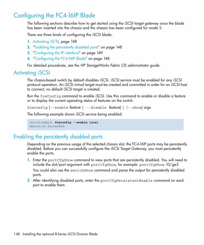
Installing the optional B-Series iSCSI Director Blade148
Configuring the FC4-16IP BladeThe following sections describe how to get started using the iSCSI target gateway once the blade has been inserted into the chassis and the chassis has been configured for mode 5.
There are three levels of configuring the iSCSI blade:
1. Activating iSCSI, page 1482. ”Enabling the persistently disabled ports” on page 1483. ”Configuring the IP interface” on page 1494. ”Configuring the FC4-16IP Blade” on page 148
For detailed procedures, see the HP StorageWorks Fabric OS administrator guide.
Activating iSCSIThe chassis-based switch by default disables iSCSI. iSCSI service must be enabled for any iSCSI protocol operation. An iSCSI virtual target must be created and committed in order for an iSCSI host to connect; no default iSCSI target is created.
Run the fosConfig command to enable iSCSI. Use this command to enable or disable a feature or to display the current operating status of features on the switch.
fosconfig [--enable feature | --disable feature] | [--show] args
The following example shows iSCSI service being enabled:
Enabling the persistently disabled portsDepending on the previous usage of the selected chassis slot, the FC4-16IP ports may be persistently disabled. Before you can successfully configure the iSCSI Target Gateway, you must persistently enable the ports.
1. Enter the portCfgShow command to view ports that are persistently disabled. You will need to include the slot/port argument with portCfgShow, for example: portCfgShow 10/ge3You could also use the switchShow command and parse the output for persistently disabled ports.
2. After identifying disabled ports, enter the portCfgPersistentEnable command on each port to enable them.
switch:admin> fosconfig --enable iscsiOperation Succeeded.

SAN Director installation guide 149
3. Enter the portCfgShow command to verify that ports are persistently enabled.
Configuring the IP interfaceIn order for iSCSI to function, the port’s IP interface needs to be configured using network settings that you can obtain from your network administrator. The portCfg commands are used to configure the following parameters necessary for the iSCSI Target Gateway:
• IP address, netmask, and MTU• IP routes• ARP resolution table
Creating the IP interface of the GbE portSpecify the IP interface on the GbE port using the portCfg command. You can define one IP interface per GbE port. The syntax for this command is:
portcfg ipif [slot/][ge]port args
The following example shows an IP interface being created for slot 8 on GbE port ge0:
Then verify the newly-created IP interface using the portShow command:
switch:admin> portcfgshow 7/ge0Persistent Disable: OFFMode: ISCSIIpif configuration:Interface IP Address NetMask MTU-----------------------------------------------0 172.1.2.3 255.255.0.0 8250 Arp configuration:IP Address Mac Address------------------------------Iproute Configuration:IP Address Mask Gateway Metric----------------------------------------------------Fciptunnel configuration:switch:admin>
switch:admin> portcfg ipif 8/ge0 create 192.168.100.40 255.255.255.0 1500
switch:admin> portshow ipif 8/ge0
Port: 8/ge0Interface IP Address NetMask MTU---------------------------------------------------------- 0 192.168.100.40 255.255.255.0 1500

Installing the optional B-Series iSCSI Director Blade150
Adding IP routes on a GbE port (Optional)After defining the IP interface of the remote switch, an IP route is automatically set up. You have the ability to define additional destination routes on an IP interface.
You can add IP routes when you want to reach the destination IP of the remote site through a preferred gateway IP. You can specify a maximum of 32 routes per GbE port. The syntax for this command is:
portcfg iproute [slot/][ge]port args
The gateway address must be on the same IP subnet as the port IP address.
The following example shows two routes being added to an interface:
Then verify that the two routes have been successfully created:
Verifying IP connectivity After you add the IP addresses of the routes, enter the portCmd command to ping a destination IP address from one of your source IP interfaces on the GbE port and verify the Ethernet IP-IP connectivity.
This verification not only ensures that data packets can be sent to the remote interface, but also aids in creating and modifying the ARP table:.
switch:admin> portcfg iproute 8/ge0 create 192.168.101.0 255.255.255.0 192.168.100.1 1switch:admin> portcfg iproute 8/ge0 create 192.168.102.0 255.255.255.0 192.168.100.1 1
switch:admin> portshow iproute 8/ge0
Slot: 8 Port: ge0IP Address Mask Gateway Metric Flags-------------------------------------------------------------------------------192.168.100.0 255.255.255.0 192.168.100.40 0 Interface 192.168.100.0 255.255.255.0 192.168.100.41 0 Interface 192.168.101.0 255.255.255.0 192.168.100.1 1192.168.102.0 255.255.255.0 192.168.100.1 1
switch:admin> portcmd --ping 8/ge0 -s 192.168.100.40 -d 192.168.100.50Pinging 192.168.100.50 from ip interface 192.168.100.40 on 0/0 with 40 bytes of dataReply from 192.168.100.50: bytes=40 rtt=0msReply from 192.168.100.50: bytes=40 rtt=0msReply from 192.168.100.50: bytes=40 rtt=0msReply from 192.168.100.50: bytes=40 rtt=0ms
Ping Statistics for 192.168.100.50: Packets: Sent = 4, Received = 4, Loss = 0 ( 0 percent loss) Min RTT = 0ms, Max RTT = 0ms Average = 0msswitch:admin>

SAN Director installation guide 151
Adding ARP entriesIt is not necessary to create additional ARP entries for iSCSI Target Gateway to work. The ARP entries for the IP interfaces will be automatically created when you complete the route for the IP by verifying it with the ping command outlined in the previous section.
Use this command to configure additional address resolution protocol (ARP) entries for the IP interfaces on the gigabit Ethernet (GbE) port on the IP interface.
portcfg arp [slot/][ge]port args
To add an ARP entry:
Then verify the newly-created ARP entry using the portShow command::
Configuring an iSCSI interfaceThe following sections describe the steps needed to finalize iSCSI blade set up.
• ”Creating iSCSI virtual targets” on page 152• ”Creating discovery domains and domain sets” on page 153• ”Defining CHAP entries for iSCSI device authentication” on page 155• ”Finalizing the iSCSI configuration” on page 156.• ”Configuring iSCSI protocol for each iSCSI port (Optional)” on page 157
Creating iSCSI virtual targetsAn iSCSI target must be created before exposing it to the iSCSI host. You must provide the number of Logical Unit Numbers (LUNs) and the actual LUN values that are part of the created iSCSI target. This section describes the procedure to create an iSCSI target.
The iSCSI virtual target is created using physical Fibre Channel targets that you can access. The most important part about creating the iSCSI virtual target is its name. The iSCSI Qualified Name
switch:admin> portcfg arp 3/ge0 add 192.168.255.25 00:01:02:03:04:60Operation Succeeded
switch:admin> portshow arp 3/ge0
Slot: 3 Port: ge0IP Address Mac Address Flags-----------------------------------------------------------192.168.255.25 00:01:02:03:04:60 Permanent Resolved Operation Succeeded

Installing the optional B-Series iSCSI Director Blade152
(IQN) is an iSCSI node name in readable notation. The name always starts with “iqn” and includes the uses Internet domain and the year and month on which the Internet domain was assigned:
iqn.yyyy-mm.<reverse of DNS>:<optional unique SCSI string>
Below is an example of a virtual target node name which follows the above naming convention, not including the optional SCSI string):
Example: iqn.2005-10.com.company:tgt1
iscsicfg [--create | --modify | --delete | --clear | --show | --commit] tgt args
To create a virtual target, use the iscsicfg --create command with the -tgt and -t operands:
After creating the iSCSI target, add the FC devices and the corresponding LUNs to it as follows:
iscsicfg [--add] lun -t target_name -w fc_wwn -l LUN_map args
Then verify the addition of devices and LUNs:
iscsicfg [--show] lun -t target_name
Use the fcLunQuery command to find out which LUNs are available to add to the iSCSI target:
The list of available FC targets in the fabric with the LUN configuration can be displayed using the fcLunQuery command, which lists the LUN IDs of the LUN(s) that are exposed. The WWN argument is optional. If no argument is specified, LUNs for all accessible targets in the fabric are displayed. You can specify either port or node WWNs.
fclunquery [-w wwn]
To view the available LUNs, use the fcLunQuery command:
Once you have the port WWN of the LUN you want to add to the iSCSI target, you can add the LUN map to the target with the specified target name. FC WWN provides the port WWN of the physical FC target and the LUN map maps the physical FC LUNs to virtual iSCSI LUNs. The LUN mapping is specified as a pair: virtual LUNs:physical LUNs
switch:admin> iscsicfg –-create tgt –t iqn.2005-10.com.company:tgt1Operation Succeeded
switch:admin> fclunquery Target Index: 1Target Node WWN: 50:05:07:65:05:03:f9:39Target Port WWN: 50:05:07:65:05:83:f9:39Target Pid: 144e8Number of LUNs returned by query: 1LUN ID: 0x00

SAN Director installation guide 153
To add a Fibre Channel device to an existing virtual target, use the iscsicfg --add command with the -tgt and -t operands:
Once the iSCSI target configuration is committed to the configuration database, the iSCSI target will be accessible to the iSCSI host during the discovery process.
Creating discovery domains and domain setsDiscovery domains are analogous to zones and discovery domain sets are analogous to zone sets. When there are no discovery domain or discovery domain sets defined, then all the iSCSI hosts have access to all iSCSI targets.
NOTE: Only IQNs can be used as an entry to establish access control.
A Fibre Channel feature, Default Zoning, disallows access to all hosts when cfgDisable and cfgClear are run. iSCSI ports function the same way for any action based on default zoning. In other words, if default zoning is on and cfgDisable and cfgClear are run, the iSCSI hosts are also denied access to the iSCSI virtual targets irrespective of a discovery domain set defined. To avoid this behavior, verify that default zoning is turned off. The discovery domain set is activated only after a cfgEnable is performed.
NOTE: Neither the discovery domain nor the discovery domain set are deleted when you run cfgDisable and cfgClear.
Creating discovery domainsA discovery domain provides the flexibility to define the host-to-target access as follows:
iscsicfg [--create | --show | --add | --delete | --clear] dd [-d DD name] [–m DD_Members] args
To create a discovery domain, run the iscsicfg --create dd command with the -d and -m operands using a comma to separate members::
Creating/enabling discovery domain setsOnce a discovery domain is created, it can be added to the discovery domain set to enable the configuration. The discovery domain set contains discovery domains. More than one discovery
switch:admin> iscsicfg –-add lun –t iqn.2005-10.com.brocade.tgt1 –w 22:00:00:04:cf:20:5d:33 –l 0:0Operation Succeeded
switch:admin> iscsicfg --create dd -d mynewdd -m iqn.2222-23.mytest1,iqn.2343-58.newtest1Operation Succeeded

Installing the optional B-Series iSCSI Director Blade154
domain set can be created/defined but only one can be enabled at any point in time. The active/enabled discovery domain set will be enforced across all the switches in the fabric.
When you execute commit, the switch on which the command is executed will become the master and will merge the discovery domain database to the rest of the IP-aware switches. Then use iscsicfg show fabric to verify the database merge.
iscsicfg [ --create | --show | --add | --delete | --enable | --disable ] ddset [-n DD Set name] [–d DD_Names] args
NOTE: If there is a conflict, then the database on the rest of the switches will be overridden by the database on the current switch (which initiated the merger) and intervention is needed to clear the conflict. However, the rest of the switches will function normally. There is no segmentation of E_Ports when the discovery domain set database conflicts.
To create a discovery domain set, use the iscsicfg --create ddset command with the -n and -d operands::
An explicit enable operation needs to be done to enable the discovery domain set. To enable the newly created DDSet, use the following command::
Defining CHAP entries for iSCSI device authenticationThe modify command can be used only for changing the authentication method for a target from None to CHAP or CHAP to None. If nothing is specified, no authentication method is enforced. If CHAP is specified, then either one-way or mutual CHAP enforcement will be performed based on the login frame from host.
iscsicfg < --create | --show | --modify | --delete | --clear > auth [-u username] [–s CHAP_Secret] args
To modify the authentication method for a target, use the iscsicfg --modify command as follows:
switch:admin> iscsicfg --create ddset -n myddset -d mydd,mynewddOperation Succeeded
switch:admin> iscsicfg –-enable ddset –n myddsetOperation Succeeded
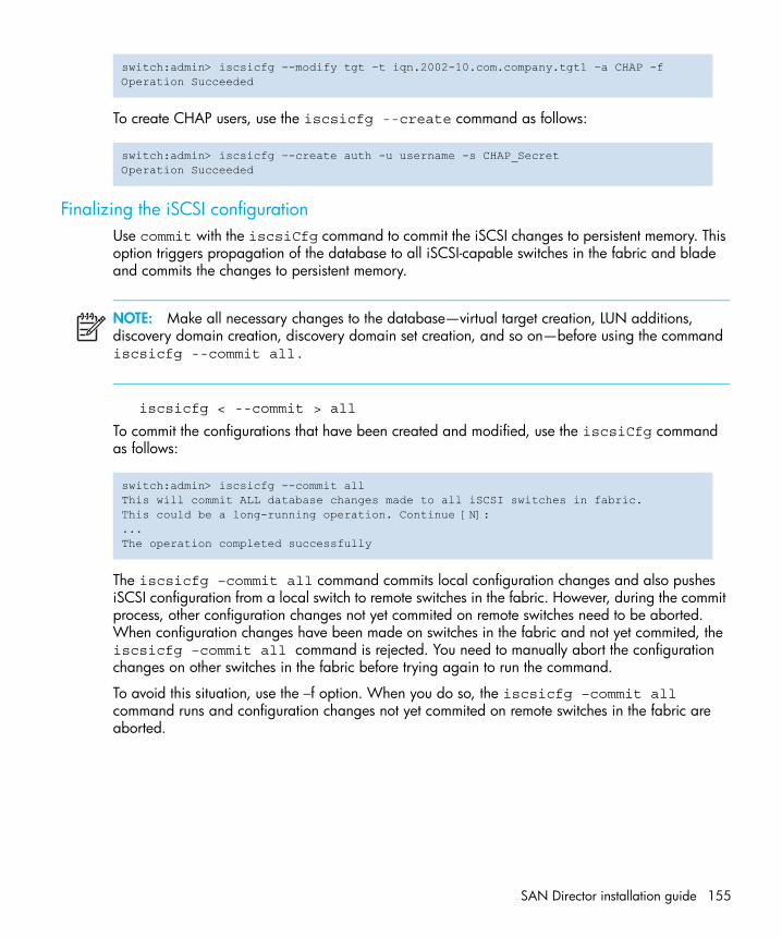
SAN Director installation guide 155
:
To create CHAP users, use the iscsicfg --create command as follows::
Finalizing the iSCSI configurationUse commit with the iscsiCfg command to commit the iSCSI changes to persistent memory. This option triggers propagation of the database to all iSCSI-capable switches in the fabric and blade and commits the changes to persistent memory.
NOTE: Make all necessary changes to the database—virtual target creation, LUN additions, discovery domain creation, discovery domain set creation, and so on—before using the command iscsicfg --commit all.
iscsicfg < --commit > all
To commit the configurations that have been created and modified, use the iscsiCfg command as follows::
The iscsicfg –commit all command commits local configuration changes and also pushes iSCSI configuration from a local switch to remote switches in the fabric. However, during the commit process, other configuration changes not yet commited on remote switches need to be aborted. When configuration changes have been made on switches in the fabric and not yet commited, the iscsicfg –commit all command is rejected. You need to manually abort the configuration changes on other switches in the fabric before trying again to run the command.
To avoid this situation, use the –f option. When you do so, the iscsicfg –commit all command runs and configuration changes not yet commited on remote switches in the fabric are aborted.
switch:admin> iscsicfg --modify tgt –t iqn.2002-10.com.company.tgt1 –a CHAP -fOperation Succeeded
switch:admin> iscsicfg –-create auth -u username -s CHAP_SecretOperation Succeeded
switch:admin> iscsicfg --commit allThis will commit ALL database changes made to all iSCSI switches in fabric.This could be a long-running operation. Continue [N]:...The operation completed successfully

Installing the optional B-Series iSCSI Director Blade156
Configuring iSCSI protocol for each iSCSI port (Optional)Each iSCSI port can be configured to operate using different iSCSI protocol parameters. These parameters are negotiated during the iSCSI login phase. The parameters that can be configured are:
• Error recovery level—Support for iSCSI error recovery level up to 2• TCP connections per session—Support of up to 2 TCP connections per iSCSI session. The
connections can be on the same iSCSI port or span two iSCSI ports on the same blade.• Header Digest—CRC32c operation for iSCSI header protection• Data Digest—CRC32c operation for iSCSI data protection• Immediate Data• First Burst Length—Amount of immediate data that can come in to the iSCSI port with the write
command; Immediate Data also needs to be enabled.iscsiportcfg [--modify | --show | --clearstats | --default] [slot_number/]port_number
The following example shows how to configure the parameters described above for slot 7 and port ge0:
The following example shows how to display the configured port parameters:
switch:admin> iscsiportcfg --modify 7/ge0Please specify parameters to modifyUsage: iscsiportcfg [--modify | --show | --clearstats | --default] [SlotNumber/]PortNumber[-h (help)][-e (error recovery level) 0...2][-c (TCP connections/session) 1...2][-a (header digest) 0-disable 1-enable][-d (data digest) 0-disable 1-enable][-i (immediate data) 0-disable 1-enable][-f (first burst length) 512 | 1024 | 2048 | 4096 | 8192 | 16384 | 32768]switch:admin> switch:admin> iscsiportcfg --modify 7/ge0 -f 32768 -e 2 -c 2 -i 1 -a 1 -d 1The operation completed successfully.
switch:admin> iscsiportcfg --show 7/ge0 The configured port parameters for slot 7 and port ge0 are:Header Digest: OnData Digest: OnFirst Burst Length: 32768Error Recovery Level: 2Immediate Data: OnConnections per session: 2Num. of active sessions on port: 0...

SAN Director installation guide 159
7 Replacing the chassisThe 4/256 SAN Director chassis is highly reliable and unlikely to fail. This chapter describes how to remove and replace a chassis in the event of a failure.
Refer to the following sections of this chapter for specific information:
• Replacing the chassis — items required, page 160• How to determine whether or not to replace the chassis, page 160• Record critical switch and SAN information, page 160• Disconnect from network and fabric, page 166• Remove components from chassis, page 166• Remove and replace chassis, page 167• Install components into new chassis, page 168• Install modems (optional), page 169• Verify correct operation of hardware, page 169• Configure new chassis serial number, page 170• Verify correct operation of system, page 171• Reconnect system to network and fabric, page 173• Verify correct configuration of fabric, page 174• Cable routing table, page 176The 4/256 SAN Director must be removed from the fabric and powered off to perform this procedure. Contact HP Technical Support if you have any questions about whether the chassis requires replacement.
CAUTION: Inform your SAN administrator that the 4/256 SAN Director must be disconnected from the fabric for the duration of the mechanical replacement and that root login is required.
If the switch is installed in a cabinet, ensure that the cabinet is balanced and secured mechanically and that the removal and installation procedure will not compromise cabinet stability.
Disassembling any part of the chassis voids the part warranty and regulatory certifications. The chassis itself contains no user-serviceable parts.

Replacing the chassis160
Replacing the chassis — items requiredThe chassis replacement procedure takes approximately 3 hours to complete. Obtain the following before starting the chassis replacement procedure:
• Electrostatic discharge (ESD) grounding strap• ESD grounding pads for protecting control processor (CP) cards, port blades, and the WWN
card• Serial cable and workstation computer with a terminal emulator application (such as
HyperTerminal for Windows systems or TIP for Solaris systems), required only if serial console session used.
• Pallet jack or hydraulic or assisted lift that raises a minimum of 55 inches (140 cm) and carries a minimum of 250 lbs. (113 kg)
• A surface to place the old chassis on, such as a second lift or the pallet originally provided with the old chassis
• 1/2 inch socket wrench to remove the pallet bolts• Torque wrench with #2 Phillips screwdriver tip (if switch is installed in a cabinet)• #2 slotted screwdriver
How to determine whether or not to replace the chassisIf you have not already done so, confirm that you need to replace the chassis before continuing. The following events might indicate that the chassis is faulty:
• Visible mechanical damage to the chassis, including damage to sheet metal or card guides that prevents correct installation of a CP card or port blade.
• Bent or damaged connectors on the main backplane (the surface inside the chassis to which CP cards and port blades connect) or on the blower backplane (the surface to which the blower assemblies connect).
• One or more 4/256 SAN Director components (such as a power supply, blower assembly, port blade, CP card, or WWN card) do not function properly even after the component is replaced.
• An AC power switch shuts off automatically even though all power supplies are removed from the chassis.
• The psShow or fanShow commands continue to show a faulty component even though the component has been replaced.
• The slotShow command continues to show a faulty CP card or port blade even though the blade has been replaced.
Record critical switch and SAN informationAll commands must be entered from a CLI session (telnet or serial) to the active CP card unless otherwise indicated. For detailed information about Fabric OS commands, refer to the Fabric OS command reference manual. Use a checklist to ensure that all required information is recorded (see Table 42 on page 165).

SAN Director installation guide 161
To record critical switch and SAN information:
1. Open a telnet session and login to the 4/256 SAN Director as admin. The default passwords “password”. Enable the logging function on your telnet or serial console connection.
2. Back up the current configuration.
Type configUpload; then, enter the requested information at the prompts.
NOTE: The configUpload command can be entered through a telnet or serial session, but you must have an Ethernet connection between the 4/256 SAN Director and the server name or IP of the host to complete the upload process. For more information, refer to the help configUpload command or the Fabric OS command reference manual.
This command uploads the switch configuration to the customer-defined FTP server, making it available for downloading if required later on. For more information about this command, refer to the Fabric OS command reference manual.
3. Record the 4/256 SAN Director values on a workstation (see step 4, next, through step 9).
4. Record the WWN value: Type wwn; then, copy the command output into a file named “config-miscinfo.txt”.
5. Record the IP address information.
swDir:admin> configuploadServer Name or IP Address [host]: 123.123.123.123User Name [None]: Admin24File Name [config.txt]: config-switch0.txtPassword: xxxxxxxxupload completeswDir:admin>
swDir:admin> wwn10:00:00:60:69:00:00:0a

Replacing the chassis162
Type ipAddrShow -sw; then, copy the command output into the “config-miscinfo.txt” file.
6. Display and record the manufacturer serial numbers.
Type chassisShow; then, copy the command output into the “config-miscinfo.txt” file.
swDir:admin> ipaddrshow
SWITCHEthernet IP Address: 10.32.50.12Ethernet Subnetmask: 255.55.0.0Fibre Channel IP Address: 1.2.3.4Fibre Channel Subnetmask: 255.255.255.0
CP0Ethernet IP Address: 10.32.50.10Ethernet Subnetmask: 255.55.0.0HostName : cp0Gateway Address: 10.32.40.1
CP1Ethernet IP Address: 10.32.50.11Ethernet Subnetmask: 255.55.0.0HostName : cp1Gateway Address: 10.32.40.1
Backplane IP address of CP0 : 10.0.0.5Backplane IP address of CP1 : 10.0.0.6swDir:admin>swDir:admin>

SAN Director installation guide 163
“Factory Serial Num” and “Serial Num” are listed under “Chassis/WWN Unit 1.” If the current WWN card is the original card, the factory serial number listed is the same as the chassis serial number provided on the bar code sticker inside the door of the chassis. If a “Serial Num” value displays, contact HP to determine whether this serial number should be modified after the new WWN card is installed.
7. Create a SAN “profile” by entering and recording the information provided by the following commands:
• nsShow
• nsAllShow
• switchShow
• fabricShow
swDir:admin> chassisshow
Chassis Backplane Revision: 1F
SW BLADE Slot: 1Header Version: 2Power Consume Factor: -50Factory Part Num: 60-0001532-03Factory Serial Num: KP000000195Manufacture: Day: 1 Month: 1 Year: 2000Update: Day: 14 Month: 3 Year: 2005Time Alive: 187 daysTime Awake: 3 days
<output truncated>
CHASSIS/WWN Unit: 1 (in same assembly as WWN Unit: 2)Header Version: 2Power Consume Factor: -3Factory Part Num: 60-0001501-07Factory Serial Num: FT02X805BE2Manufacture: Day: 26 Month: 3 Year: 2003Update: Day: 14 Month: 3 Year: 2005Time Alive: 207 daysTime Awake: 3 days
<output truncated>
swDir:admin>

Replacing the chassis164
Copy the command output into a text file named “SANbefor.txt”. This information can be used after the 4/256 SAN Director is restored to the fabric, to verify that no unintentional changes have occurred to the fabric.
8. Type supportShow; then, copy the command output into a text file named “spptshow.txt”.
NOTE: The supportshow command has very long output and time for completion can last between 2 and 20 minutes or longer depending on the size of your SAN.
This file provides a backup of all the information that might be required by HP Technical Support. The information can be used after the switch is restored to the fabric, to verify that no unintentional changes have occurred to the fabric.
swDir:admin> nsshowType Pid COS PortName NodeName TTL<output truncated>
swDir:admin> nsallshow12 Nx_Ports in the Fabric
<output truncated>
swDir:admin> switchshowswitchName: switch<output truncated>
swDir:admin> fabricshowSwitch ID Worldwide Name Enet IP Addr FC IP Addr Name<output truncated>
swDir:admin>
swDir:admin> supportshowversion: 5.0.1<output truncated>
swDir:admin>

SAN Director installation guide 165
9. Record the cable connections between the 4/256 SAN Director and the target device and ports (see Table 42).
NOTE: Copying the individual switch configurations, miscellaneous configuration information, SAN profile, and supportShow output into text files is recommended. Recommended file names are “config-switch.txt,” “config-miscinfo.txt,” “SANbefor.txt,”and “spptshow.txt,” respectively.
Table 42 Critical information checklist
Configuration information
Location of “config-switch.txt” file:
Location of “config-miscinfo.txt” file:
IP address, subnet mask:
WWN for Director:
SAN profile
Location of “SANbefor.txt” file:
Notes regarding nsshow output:
Notes regarding nsallshow output:
Notes regarding switchshow output:
Notes regarding fabricshow output:
Output from supportshow command
Location of “spptshow.txt” file:
Notes regarding supportshow output:
Information About the New Chassis
New Factory Serial Num:
New Serial Num (if available):
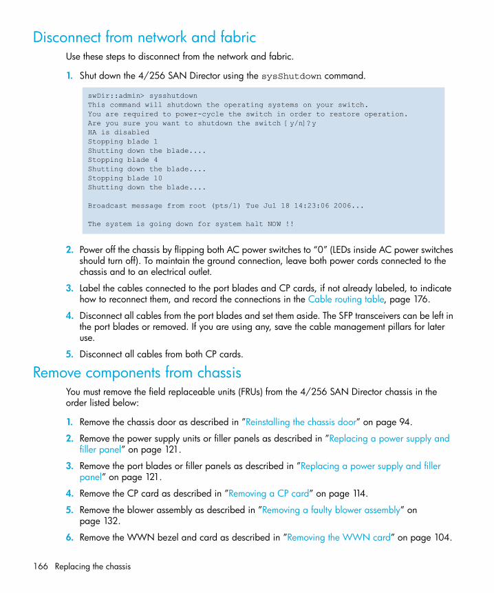
Replacing the chassis166
Disconnect from network and fabricUse these steps to disconnect from the network and fabric.
1. Shut down the 4/256 SAN Director using the sysShutdown command.
2. Power off the chassis by flipping both AC power switches to “0” (LEDs inside AC power switches should turn off). To maintain the ground connection, leave both power cords connected to the chassis and to an electrical outlet.
3. Label the cables connected to the port blades and CP cards, if not already labeled, to indicate how to reconnect them, and record the connections in the Cable routing table, page 176.
4. Disconnect all cables from the port blades and set them aside. The SFP transceivers can be left in the port blades or removed. If you are using any, save the cable management pillars for later use.
5. Disconnect all cables from both CP cards.
Remove components from chassisYou must remove the field replaceable units (FRUs) from the 4/256 SAN Director chassis in the order listed below:
1. Remove the chassis door as described in ”Reinstalling the chassis door” on page 94.
2. Remove the power supply units or filler panels as described in ”Replacing a power supply and filler panel” on page 121.
3. Remove the port blades or filler panels as described in ”Replacing a power supply and filler panel” on page 121.
4. Remove the CP card as described in ”Removing a CP card” on page 114.
5. Remove the blower assembly as described in ”Removing a faulty blower assembly” on page 132.
6. Remove the WWN bezel and card as described in ”Removing the WWN card” on page 104.
swDir::admin> sysshutdownThis command will shutdown the operating systems on your switch.You are required to power-cycle the switch in order to restore operation.Are you sure you want to shutdown the switch [y/n]?yHA is disabledStopping blade 1 Shutting down the blade....Stopping blade 4 Shutting down the blade....Stopping blade 10 Shutting down the blade....
Broadcast message from root (pts/1) Tue Jul 18 14:23:06 2006...
The system is going down for system halt NOW !!

SAN Director installation guide 167
7. Remove power cords.
8. Remove the cable management comb as described in ”Removing a cable management comb” on page 98.
WARNING! If the 4/256 SAN Director is installed in a cabinet, ensure that the cabinet is balanced and mechanically secured, and that the removal and installation procedure will not compromise cabinet stability.
CAUTION: To prevent damage to the equipment from ESD:
1. Ensure that the 4/256 SAN Director is grounded when removing or installing static-sensitive components. This can be accomplished by leaving the power cords attached to the chassis and a power source or by implementing standard ESD precautions, such as placing the chassis on a grounded bench.
2. Wear an ESD grounding strap when handling the CP cards, 16-port blades, and WWN card.
3. Protect the CP cards, 16-port blades, and WWN card with static bags or grounding pads while they are out of the chassis.
Remove and replace chassis
WARNING! An empty 4/256 SAN Director chassis weighs approximately 108 lbs (47 kg) and requires a hydraulic or assisted lift to move.
If the switch is installed in a cabinet, ensure that the cabinet is balanced and mechanically secured and that the removal and installation procedure will not compromise cabinet stability.
Do not place a 4/256 SAN Director chassis on the floor. It cannot be easily moved from the floor back onto a lift or pallet
1. Uninstall the 4/256 SAN Director chassis from the installation location and place it onto an extra lift or on the shipping pallet originally provided with the chassis. If the chassis is in a cabinet, uninstall it from the cabinet, remove the rack mount hardware according to the manufacturer’s instructions, and set the hardware aside for use with the new chassis.
2. Unpack the new chassis:
a. Use scissors to cut the two bands that encircle the packaging.
b. Lift off the lid and remove the kits and foam from the top of the chassis.

Replacing the chassis168
c. Lift the cardboard box off the chassis and remove the plastic bag from around the chassis. Save packing materials for use when returning the old chassis.
d. Leave chassis attached to pallet if chassis must be transported to the installation location.
3. Transport the new chassis to the installation area, using a pallet jack or other assisted lift. If a pallet jack is available, place the tines into the gaps under the chassis.
Doorways must be wider than 36 inches (91 cm) to accommodate the chassis on the pallet.
4. Remove the pallet brackets and bolts:
a. Remove the four bolts holding the chassis to the pallet, using the 1/2 inch socket wrench.
b. Remove the four brackets from bottom of the chassis.
c. Save the pallet, pallet brackets, and pallet bolts for use when returning the faulty chassis, if required.
5. Install the chassis in the cabinet or other installation location, as applicable, using a lift if necessary to raise the chassis to the correct level. If installing the chassis in a cabinet, follow the instructions provided by the rack kit manufacturer.
CAUTION: To ensure adequate cooling install the chassis with the cable side, which contains the airtake vents, facing the cool air aisle.
Install components into new chassis
CAUTION: Do not force the installation of any of the components. If the component does not slide in easily, ensure that it is correctly aligned and positioned before continuing.
Do not turn on the power until it is time to verify hardware operation (see step 1 on page 149).
1. Install the cable management comb on the new chassis, as described in ”Installing the cable management pillars (optional)” on page 99.
2. Verify that both AC power switches are off (set to “0”); then, connect power cords and power cord retainers (which should still be on the cords) to the new chassis:
a. Connect the power cords to the power connectors on the chassis. The power cords are designed with right and left bends to facilitate cord management. Ensure that the power cord has a minimum service loop of 6 inches available at the connection to the switch and that it is routed so that it is not exposed to stress.
b. Tighten the adjusting screw on each retainer until the power cord cannot be pulled out of the retainer. This prevents accidental disconnection from the chassis.
c. Connect the power cords to a power source with voltage of 200 to 240 VAC, 50-60 Hz.

SAN Director installation guide 169
NOTE: To protect against AC power failure, a separate power source is recommended for each cord. Routing the power cables out the sides of the chassis is recommended.
CAUTION: Do not turn the AC power switches on (set to “0”) until you verify the hardware of the system (see ”Verify correct operation of system” on page 171)
3. Put on an ESD grounding strap and attach it to the grounding strap connector on the chassis (see Figure 1 on page 23 for location of grounding connector).
4. Install the WWN card and bezel in the new chassis as described in Installing a WWN card, page 108.
5. Install the blower assembly as described in ”Installing a replacement blower assembly” on page 132
6. Install the CP cards in the new chassis as described in ”Installing a new CP card” on page 116.
7. Install the port blades (and filler panels if applicable) in the new chassis as described in Replacing a port blade, page 124.
8. Reinstall the door as described in ”Reinstalling the chassis door” on page 94.
Install modems (optional)The 4/256 SAN Director detects modems only during power on or reboot. If a modem is connected to an operating switch, a reboot is required for the 4/256 SAN Director to detect the modem.
If modems are in use, reconnect modem cables to the CP cards.
For modem installation instructions, refer to ”Connecting modems” on page 179.
Verify correct operation of hardwareFollow these steps to power on the system and verify that the hardware is operating correctly.
1. Turn on both AC power switches by positioning them to “1”. The LEDs inside the AC power switches light up green when power is being supplied.
By default, the 4/256 SAN Director automatically performs a power-on self-test (POST) each time it is powered on. POST takes a minimum of three minutes and is complete when LED activity returns to standard state.
2. Verify that the 4/256 SAN Director is powered on and POST is complete (all power LED indicators on the port blades and CP cards should be a steady green).
3. Verify that all components are functioning correctly by checking the LEDs for each component.
If the LEDs do not indicate a standard healthy state, try reinstalling the corresponding component.

Replacing the chassis170
Configure new chassis serial numberUse these steps to configure a new chassis serial number.
1. Open a CLI session (telnet or serial) and log in as root. The root and factory account disclaimer displays:
2. Change the Factory Serial Number to the serial number of the new chassis (the serial number is provided on the barcode sticker on the port side of the new chassis):
a. Type fruInfoSet chassis 1 at the prompt.
b. Type the OEM serial number, if any, at the “SN” prompt.
c. Type the chassis serial number at the “Chassis SN:” prompt.
Fabric OS (swDir)login: rootPassword:Disclaimer for Root and Factory Accounts Usage!
This Fibre Channel switch is equipped with Root and Factory accountsthat are intended for diagnostics and debugging purposes solely bythe Equipment vendor's trained engineers. Improper use of thefunctionality made available through the Root or Factory account couldcause significant harm and disruption to the operation of the SAN fabric.
Your use of the functionality made available through the Root or Factoryaccount is at your sole risk and you assume all liability resulting fromsuch use. The Equipment vendor shall have no liability for any lossesor damages arising from or relating to the use of the Root or Factoryaccount (and the functionality enabled thereby) by anyone other thanthe Equipment vendor's authorized engineers.
Proceeding with the usage of this switch as the Root or Factory userexplicitly indicates your agreement to the terms of this disclaimer.
swDir:root>

SAN Director installation guide 171
d. Verify that the command shows the correct serial numbers.
3. Verify that the chassis serial number has been entered correctly by typing chassisShow at the prompt.
Verify correct operation of systemTo verify that the 4/256 SAN Director is operating correctly:
1. Log in to the 4/256 SAN Director as admin:
2. Type slotShow command and verify that all the installed cards are detected and that their status is operational (enabled).
swDir:root> fruinfoset chassis 1 ID: (none) > PN: (none) > SN: (none) > OEMssn12345 RV: (none) > Chassis SN: (none) > FT00X8008A4
New FRU Info for: chassis(wwn) 1 ID: none PN: none SN: OEMssn12345 RV: none Chassis SN: FT00X8008A4swDir:root>
swDir:root> loginlogin: adminpassword: xxxxxxxxswDir:admin>
swDir:admin> slotshow
Slot Blade Type ID Status --------------------------------- 1 AP BLADE 24 ENABLED 2 SW BLADE 18 ENABLED 3 SW BLADE 36 ENABLED 4 AP BLADE 24 ENABLED 5 CP BLADE 16 ENABLED 6 CP BLADE 16 ENABLED 7 SW BLADE 18 ENABLED 8 SW BLADE 36 ENABLED 9 SW BLADE 36 ENABLED 10 AP BLADE 31 ENABLED
swDir:admin>

Replacing the chassis172
3. Verify that the 4/256 SAN Director is functioning correctly by typing switchShow or switchStatusShow.
This switchShow command displays switch and port status information.
4. Verify that all the IP address information is correct by typing ipAddrShow and checking the results against the IP information recorded in the “config-miscinfo.txt” file.
swDir:admin> switchshowswitchName: swDirswitchType: 42.0switchState: OnlineswitchMode: NativeswitchRole: PrincipalswitchDomain: 2switchId: fffc02switchWwn: 10:00:00:60:69:80:5b:e2zoning: ON (c3)switchBeacon: OFFblade1 Beacon: OFFblade3 Beacon: OFFblade9 Beacon: OFF
Area Slot Port Media Speed State===================================== 1 1 0 id N4 Online F-Port 10:00:00:00:c9:29:0e:77<output truncated>
swDir:admin>
swDir:admin> ipaddrshow
SWITCHEthernet IP Address: 10.32.50.12Ethernet Subnetmask: 255.55.0.0Fibre Channel IP Address: 1.2.3.4Fibre Channel Subnetmask: 255.255.255.0
CP0Ethernet IP Address: 10.32.50.10Ethernet Subnetmask: 255.55.0.0HostName : cp0Gateway Address: 10.32.40.1
CP1Ethernet IP Address: 10.32.50.11Ethernet Subnetmask: 255.55.0.0HostName : cp1Gateway Address: 10.32.40.1
Backplane IP address of CP0 : 10.0.0.5Backplane IP address of CP1 : 10.0.0.6swDir:admin>swDir:admin>

SAN Director installation guide 173
Reconnect system to network and fabricRefer to the cable routing information recorded in Table 43 on page 176 for the following steps:
1. Connect the CP cards to the local area network:
a. Refer to the cable routing information recorded earlier and insert the appropriate Ethernet cables into each Ethernet port.
b. Connect the other ends to an Ethernet 10/100 Base-T LAN, if not already connected.
NOTE: The 4/256 SAN Director can be accessed by remote connection using any of the available management tools, such as telnet or Advanced Web Tools. Ensure that the Director is not modified from other connections during the rest of this procedure
2. Reconnect the transceivers and cables to the port blades, as required:
NOTE: The ports and cables used in trunking groups must meet specific requirements. For a list of these requirements, refer to the HP StorageWorks Fabric OS administrator guide.
a. Position one of the transceivers so that the key is oriented correctly to the port and insert the transceiver into the port until it is firmly seated and the latching mechanism clicks.
Transceivers are keyed so that they can only be inserted with the correct position. If a transceiver does not slide in easily, ensure that it is correctly positioned. For instructions that are specific to the transceiver model, refer to the transceiver manufacturer’s documentation.
b. Select the cable that corresponds to the port and position it so that the key (the ridge on one side of the cable connector) is aligned with the slot in the transceiver; then, insert the cable into the transceiver until the latching mechanism clicks.
Cables are keyed so that they can only be inserted in the correct position. If a cable does not slide in easily, ensure that it is correctly positioned. For instructions that are specific to the cable type, refer to the cable manufacturer’s documentation.
c. Repeat steps a and b for the remaining ports.
CAUTION: Do not route cables in front of the air exhaust vent (located on the upper port side of the chassis).
The minimum bend radius for a 50-micron cable is 2 inches under full tensile load and 1.2 inches with no tensile load.
Tie wraps are not recommended for optical cables because they are easily overtightened.

Replacing the chassis174
d. Organize the cables as required. To use the cable management pillars, insert the cables into the holes in the pillars, using a separate hole for each cable. The cables can be routed to either side of the management comb or down through the holes in the comb.
Verify correct configuration of fabricCopying the command outputs from this section into a file is recommended.
To verify correct configuration of the fabric:
1. Create an “after” SAN profile by entering the following commands and copying the output to a text file named “SANafter.txt”:
• nsShow
• nsAllShow
• switchShow
• fabricShow
2. Determine any differences between the information in the “SANafter.txt” file and the information in the “SANbefor.txt” file created earlier. In particular, look for differences in the following:
• Device types
• Number of devices
• ISL and port states
• Number of switches in the fabric
swDir:admin> nsshowType Pid COS PortName NodeName TTL(sec) N 020f00; 3;10:00:00:01:73:00:29:46;10:00:00:01:73:00:29:46; na Fabric Port Name: 20:0f:00:60:69:90:03:f0<output truncated>
swDir:admin> nsallshow{ 020f00 021fda 021fdc 021fe0 021fe15 Nx_Ports in the Fabric}
swDir:admin> switchshowswitchName: swDir<output truncated>
swDir:admin> fabricshowSwitch ID Worldwide Name Enet IP Addr FC IP Addr Name<output truncated>
swDir:admin>

SAN Director installation guide 175
3. Resolve any issues or unintentional changes to the 4/256 SAN Director or fabric.
• If there are any mechanical problems, try reseating the associated component.
• If the configuration information is not correct for the 4/256 SAN Director, modify as required. If necessary, the configuration saved before the replacement can be downloaded using the configDownload command.
The configDownload command can be entered through a telnet or serial session, but the 4/256 SAN Director must have an Ethernet connection to the server name or IP of the host for the download process to complete. For more information, refer to the help configdownload command or the Fabric OS command reference manual.
• If other issues exist, contact HP.
4. If required, package the faulty chassis for return to HP.
CAUTION: If the old chassis is returned to HP, ensure that the packaging is strong enough to contain the chassis and is securely fastened. If the cardboard packaging is used, you must use banding equipment to enclose the package with a minimum of two bands around the entire package.
swDir:admin> configdownloadServer Name or IP Address [host]: 123.123.123.123User Name [None]: Admin24File Name [config.txt]: config-switch.txtPassword: xxxxxxxxdownload completeswDir:admin>

Replacing the chassis176
Cable routing tableTable 43 provides a sample of cable routing information.
Table 43 Sample cable routing table for 4/256 SAN Director (switch name: swDir)
Slot/Port Cable labels Device connected to Slot/Port of device
Switch end Device end
Slot 1 Port 0 North 24 - 1/0
East 26 - 0 SW3200 East 26 0
Slot 5 Serial North 24 - 5/Serial
Work 5 - 2 Workstation 5 Com 2
Slot 8 Port 15 North 24 - 8/15
RAID 16 - 4 RAID 16 4

SAN Director installation guide 177
8 Setting up and installing modemsThis chapter provides the following information:
• Using high availability connectivity, page 177 • Connecting modems, page 179• Setting up a remote modem system, page 180• Verifying the modem connection, page 181Each CP card in the 4/256 SAN Director contains a modem serial port for connection to a Hayes-compatible modem. The modem serial ports are wired as standard DTE ports and have the same commands, log in capabilities, and operational behavior as the terminal serial ports. However, asynchronous informational messages and other unsolicited text are not sent to the modem ports. No additional software is required to use modems with the 4/256 SAN Director.
NOTE: The 4/256 SAN Director detects modems only during power-on, reboot, or a CP card failover sequence. Setting up the modems before powering on the 4/256 SAN Director is recommended.
For increased security, any active modem sessions are automatically disconnected if the modem cable is disconnected.
For optimal security, disconnect the modem cable when it is not in use.
Using high availability connectivityHigh availability of the modem connection can be ensured by connecting a separate modem to each CP card and then connecting both modems to a shared telephone line (see Figure 39). This ensures an available telephone connection to the active CP card even if a failover occurs; however, it is necessary to log back in after a failover. When both CP cards are connected to a shared telephone line, callers are automatically dialed in to the active CP card, which answers on the first ring. If the active CP card cannot answer for any reason, the standby CP card answers on the seventh ring and allows login to proceed.

Setting up and installing modems178
NOTE: If a modem connection is set up, connecting a modem to each CP card is recommended.
Figure 39 Two modems attached for High Availability
POWER SUPPLY 2
POWER SUPPLY 3
POWER SUPPLY 4
POWER SUPPLY 1
1 2 3 4 5 6 7 8 9 10
200-240 VAC 12A 50-60 Hz 200-240 VAC 12A 50-60 Hz
!
!
!
!
POWER SUPPLY 1 & 3 POWER SUPPLY 2 & 4
CP4
Link
10/100 Mb/s
!
Active CP
IOIO
IR
S-232
CP4
Link
10/100 Mb/s
!
Active CP
IOIO
IR
S-232
FC432
FC432
FC432
FC432
7
6
5
4
3
2
1
0
15
14
13
12
11
10
9
8
56-0000590-01RevA
!
FC416
7
6
5
4
3
2
1
0
15
14
13
12
11
10
9
8
56-0000590-01RevA
!
FC416
7
6
5
4
3
2
1
0
15
14
13
12
11
10
9
8
56-0000590-01RevA
!
FC416
7
6
5
4
3
2
1
0
15
14
13
12
11
10
9
8
56-0000590-01RevA
!
FC416
2.015
Note: Modem power connectionsnot shown
scale: 1/8" = 1"
DB-25M to DB-9FModem Cable
(1 per CP Card)
Modem Porton CP Card
(1 per CP Card;RS-232 port interface)
Terminal Porton CP Card
(1 per CP Card;10101 port interface)

SAN Director installation guide 179
Connecting modems
NOTE: Setting up the modems before powering on the 4/256 SAN Director and connecting it to the fabric is recommended.
The following items are required to set up two modems to work with the 4/256 SAN Director:
• Two Hayes-compatible modems, such as the Zoom/Modem V.92 EXT Model 3049
• Two standard modem cables, DB25 (male) to DB9 (female)
• One RJ-11 “Y” adapter for standard telco wiring or equivalent circuitry (three total connections)
• One analog telephone line
CAUTION: Powering off the 4/256 SAN Director before connecting cables to the modem ports is recommended.
To connect modems to the 4/256 SAN Director:
1. Optionally power off the 4/256 SAN Director.
2. Set up the two modem units and corresponding power connections, but do not power on the modems until all cables are attached.
3. Connect the modem cables to the modems and to the 4/256 SAN Director RS-232 modem ports, as shown in Figure 39 on page 178.
4. Connect the telephone “line” inputs on the modems to the RJ-11 “Y” connector.
This effectively places both modems on a single telephone line.
5. Optionally connect a telephone handset to one of the “phone” connections on the modems, as shown in Figure 39 on page 178.
6. Connect the “Y” adapter to an appropriate analog telephone line and document the dial-in number for later use.
7. Power on the modems and verify that the Modem Ready indicator illuminates on both units.
8. Power on the 4/256 SAN Director, or reboot if it was not powered off during the previous steps.
This allows the 4/256 SAN Director to recognize the modems.

Setting up and installing modems180
Setting up a remote modem systemAfter the modems are connected, you can use a telco system to dial in to the modems and verify that they answer and communicate as expected. If a dial-out modem facility is not available, you can use a terminal emulation program on a computer workstation (or laptop) that has an attached modem.
This procedure is only required if a dial-out modem facility is not already available for testing the 4/256 SAN Director modem connections.
To set up the optional remote modem:
1. Connect the remote modem to the workstation, as shown in Figure 40.
2. Disable any serial communication programs running on the workstation (such as a synchronization program for a Personal Data Assistant (PDA).
Figure 40 Remote modem setup
2.016
RemoteModem
AnalogTelco
DB-25Mto
DB-9FModemCable
PC or Laptoprunning
Hyperterminal

SAN Director installation guide 181
3. Launch the terminal emulator application and configure as described below. See Table 44.
4. Follow the instructions from the modem manufacturer to set up and verify modem operation.
Verifying the modem connectionThis section provides information about how to verify that the modems are correctly connected.
NOTE: This procedure requires either a telco system to dial in to the modems or a terminal emulation program on a laptop or workstation that has an attached modem. Refer to ”Setting up a remote modem system” on page 180 for instructions on setting up a remote modem with a terminal emulation program.
To verify the modem connection:
1. Verify that both modem cables are firmly connected.
2. Power on the modems, if not already on.
Table 44 Terminal emulator parameters for most Windows systems
Parameter Value
Port speed (bits per second) 115200
The port usually defaults to highest speed supported by modem; might negotiate for slower speed.
Data protocol Standard EC
Compression Enabled
Flow control Hardware
Databits 8
Parity None
Stop bits 1
Modulation Standard

Setting up and installing modems182
NOTE: The modems must be powered on and operational before the 4/256 SAN Director is powered on, to allow the 4/256 SAN Director to detect the modems during boot.
3. Verify that both modems indicate they are ready by illuminating their “Clear to Send” (CS), “Terminal Ready” (TR), and “Modem Ready” (MR) indicators. If this does not occur, ensure that the modems are connected to a power source and are powered on, and check all modem cable connections.
4. Verify that POST is complete on the 4/256 SAN Director (a minimum of 3 minutes).
5. Dial in to the telephone number assigned to the 4/256 SAN Director, using a telco system to dial-in to the modems or the setup described in ”Setting up a remote modem system” on page 180.
6. Observe the modem lamps: the Ring indicator should flash briefly as the telephone rings. If the Ring indicator does not flash on both units, recheck the incoming telephone lines to the modems.
7. Verify that after one ring, the modem associated with the active CP card (usually in slot 5), illuminates the “Off Hook” (OH) indicator on the modem and a login prompt is presented to the remote client.
8. Log in to the switch from the remote client as admin. The default password is “password”.
NOTE: If the Off Hook indicator illuminates on the standby CP card modem, recheck the modem cable connection to the active CP card.
9. Log out of the modem session.
10.Remove the telco connector from the active CP card modem, leaving the telco line from the standby CP card connected to the “Y” connector (see Figure 39 on page 178).
11. Dial in to the telephone number assigned to the 4/256 SAN Director, as described in ”Setting up a remote modem system” on page 180.
12. Observe the modem lamps: the Ring indicator should flash only on the modem connected to the standby CP card.
13. Verify that after seven rings, the Off Hook indicator on the standby CP card modem is illuminated. A login prompt is presented to the remote client, and a message confirms that the standby CP card is being logged in to. You can log in or disconnect the session, as desired.
14. Reconnect the telco connector to the active CP card modem.
The 4/256 SAN Director modems are ready for use.
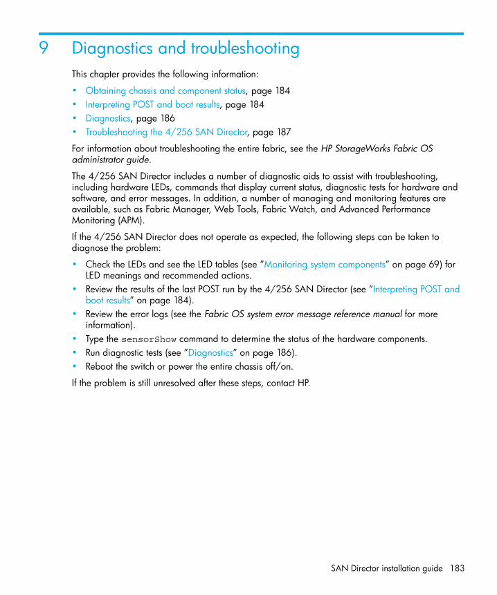
SAN Director installation guide 183
9 Diagnostics and troubleshootingThis chapter provides the following information:
• Obtaining chassis and component status, page 184• Interpreting POST and boot results, page 184• Diagnostics, page 186• Troubleshooting the 4/256 SAN Director, page 187
For information about troubleshooting the entire fabric, see the HP StorageWorks Fabric OS administrator guide.
The 4/256 SAN Director includes a number of diagnostic aids to assist with troubleshooting, including hardware LEDs, commands that display current status, diagnostic tests for hardware and software, and error messages. In addition, a number of managing and monitoring features are available, such as Fabric Manager, Web Tools, Fabric Watch, and Advanced Performance Monitoring (APM).
If the 4/256 SAN Director does not operate as expected, the following steps can be taken to diagnose the problem:
• Check the LEDs and see the LED tables (see ”Monitoring system components” on page 69) for LED meanings and recommended actions.
• Review the results of the last POST run by the 4/256 SAN Director (see ”Interpreting POST and boot results” on page 184).
• Review the error logs (see the Fabric OS system error message reference manual for more information).
• Type the sensorShow command to determine the status of the hardware components.• Run diagnostic tests (see ”Diagnostics” on page 186).• Reboot the switch or power the entire chassis off/on.
If the problem is still unresolved after these steps, contact HP.

Diagnostics and troubleshooting184
Obtaining chassis and component statusThe CLI commands listed in Table 45 on page 184 provide status and environmental information about the chassis and its components. These commands provide information only, and they do not interrupt traffic flow. For more information about these commands, see the Fabric OS command reference manual.
Interpreting POST and boot resultsThe 4/256 SAN Director performs Power On Self Test (POST) by default each time the chassis is powered on or the 4/256 SAN Director is rebooted or reset. The 4/256 SAN Director can be rebooted using the reboot (to reboot each CP individually) or fastBoot commands. The fastBoot command reboots the switches without running POST. If the active CP card is rebooted, it fails over to the standby CP card.
Table 45 Environmental status and maintenance commands
Command Information Displayed
sensorShow Temperature readings for the port blades
Temperature readings for the CP cards
Status and RPM of all operational fans
Status of all operational power supplies
tempShow Temperature readings for the port blades
Temperature readings for the CP cards
psShow Status of all operational power supplies
fanShow Status and RPM of all operational fans
chassisShow Serial number, time awake, and additional information about each component
slotShow Slot occupancy
errShowerrDump
System error log. See the Fabric OS system error message reference manual for more information on the messages in this log.

SAN Director installation guide 185
POSTEach time the switch is powered on or reset, the switch automatically performs POST, a system check during which LED patterns might vary.
To verify that POST has completed without error:
• Verify that all LEDs return to a normal state after POST completes (see ”Monitoring system components” on page 69).
• If one or more LEDs do not return to a normal state, and this is not due to the switch being set to beacon, refer to the relevant LED table to identify and correct the problem. For port blades and CP cards, the slotShow command can be used to check the status of the slots. For information about turning beaconing on/off, see the HP StorageWorks Fabric OS administrator guide.
• Verify that the switch prompt displays when POST completes.• If it does not display, POST was not successfully completed. Contact HP for support.• Review the system error log using the errShow or errDump commands.• Any errors detected during POST are written to the system log, which is accessible through the
errShow command. For information about error messages, see the Fabric OS system error message reference manual.
POST includes the following steps:
1. Preliminary POST diagnostics are run.2. Operating system is initialized.3. Hardware is initialized.4. Diagnostic tests are run on several functions, including circuitry, port functionality, ability to send
and receive frames, all aspects of memory, parity, statistics counters, and serialization.
BootIn addition to POST, boot includes the following steps after POST is complete:
1. Universal port configuration is performed.2. Links are initialized.3. Fabric is analyzed. If any ports are connected to other switches, the switch participates in a
fabric configuration.4. The switch obtains a domain ID and assigns port addresses.5. Unicast routing tables are constructed.6. Normal port operation is enabled.

Diagnostics and troubleshooting186
DiagnosticsDiagnostic tests are automatically run during POST to check the status of the switch. Any error messages generated during POST are sent to the error logs and to the serial console, if connected.
Diagnostic tests can also be run manually to test and troubleshoot the hardware and the firmware, including internal connections and circuitry, transceivers, and port cables. However, diagnostic tests are generally intended for use by support personnel.
NOTE: Error messages do not necessarily indicate that the switch requires maintenance.
Each diagnostic test can be implemented by entering the related command through a telnet or serial session. For a list of diagnostic tests and commands, see the HP StorageWorks Fabric OS administrator guide.
All diagnostic tests are run at link speeds of both 1, 2 and 4 Gb/sec. They might temporarily lock the transmit and receive speeds to a specific speed. Some diagnostic tests require interconnecting the ports to each other or using loopback plugs. If ports are interconnected, the media (cables and transceivers) at each end of the connection must be of the same type. For example, short wavelength media must be connected to short wavelength media, and likewise with long wavelength media and copper media.
For more information about diagnostic tests and how to run them, see the HP StorageWorks Fabric OS administrator guide and the Fabric OS command reference manual. For information about system error messages (errShow or errDump), see the Fabric OS system error message reference manual.

SAN Director installation guide 187
Troubleshooting the 4/256 SAN DirectorTable 46 provides a list of issues, possible causes, and recommended actions.
Table 46 Troubleshooting the 4/256 SAN Director
Issue Possible cause Recommended action
Entire chassis powers off automatically.
Power supplies are inadequate to support the installed components.
Add an additional power supply.
Several or all components are not operating.
One or both power cables may not be connected to a live source.
Ensure that both power cables are connected to live outlets.
One or both AC power switches might be off.
Ensure that both AC power switches are on (AC switches light up green when on).
Serial connection is faulty or serial port logs have incorrect or missing information.
Serial cable is not connected correctly.
Ensure that the cable is firmly connected to workstation computer and to the 4/256 SAN Director.
Terminal emulator application parameters are not set correctly.
Ensure that the terminal emulator application is configured as follows: 9600 bits per second, 8 databits, no parity, 1 stop bit, no flow control.
Serial port might be incompatible (only RS-232 is supported).
Ensure that the 4/256 SAN Director is connected to an RS-232 port. RS-423 serial ports might experience difficulties due to corner-case incompatibilities of the standards.
Pins on the serial cable or serial port might be damaged.
Remove the cable and inspect the pins on the cable and in the serial port. Do not reinstall if the pins on either component have any visible damage, as this could damage the pins on the other component. Replace components as required.

Diagnostics and troubleshooting188
Modems are not detected by switch.
Modems were connected after the 4/256 SAN Director was powered on.
Reboot the CP card(s) to which the modem(s) are connected.
Modems are connected to the wrong ports on the CP cards.
Ensure that the modem cables are connected to the ports labeled “RS232” (the serial ports intended for terminal use are labeled 10101).
Modems are not correctly configured. Verify that the modems are configured as specified in ”Setting up and installing modems” on page 177.
Pins on the modem cable or modem port might be damaged.
Remove the cable and inspect the pins on the cable and in the port. Do not reinstall if the pins on either component have any visible damage, as this could damage the pins on the other component. Replace components as required.
CP Ethernet link speed is different than expected or a link cannot be established.
There might be a conflict with the CP Ethernet link speed negotiation set up by the network.
Specify the CP Ethernet link speed by typing the ifModeSet command.
Configuration data is inaccurate or cannot be accessed.
Chassis was powered off/on while the WWN card was uninstalled or failed.
Install an operational WWN card and power the system off/on again.
The switch was rebooted while the WWN card was uninstalled or failed.
Initial set up results in IP address/Domain ID conflict.
The switch was connected to the fabric before being configured.
See the HP StorageWorks Fabric OS administrator guide for configuration information.
Table 46 Troubleshooting the 4/256 SAN Director (continued)
Issue Possible cause Recommended action

SAN Director installation guide 189
LEDs on one or more components are changing rapidly or do not indicate a healthy state.
The 4/256 SAN Director might be booting or running POST.
Verify that boot and POST are complete. The 4/256 SAN Director requires a minimum of 3 minutes, usually, after power-on to complete POST.
Beaconing might be on for the entire 4/256 SAN Director or for individual components.
Determine whether beaconing is on by typing the switchShow command and determine whether switch beaconing or blade beaconing are on.
Individual components might have failed.
See the LED tables in ”Monitoring system components” on page 69 for interpretation and recommended actions.
Pins on the components might be damaged.
Remove component from chassis and inspect pins on component and inside chassis. Do not reinstall if pins on either component are visibly damaged, as this could damage pins on other component. Replace parts as required.
None of the LEDs on an individual component are on.
Component might not be seated correctly.
Ensure that the 4/256 SAN Director has power and component is firmly seated. If problem continues, type the sensorShow command to determine component status. If component is a CP card or port blade, type the slotShow command to determine status.
Component might have failed. Replace component as necessary.
CP cards are failing over frequently.
A third-party application has a memory leak.
Check application for memory leaks.
There is excessive serial port activity. Ensure that serial port activity remains below specified amount.
CP card is attached to an ethernet with high traffic loads.
Ensure that ethernet traffic remains below specified amount
Chassis is overheated. Type the sensorShow command to check internal temperature. If components are overheating, shut down port blades as necessary to return the temperature to operating range.
Table 46 Troubleshooting the 4/256 SAN Director (continued)
Issue Possible cause Recommended action

Diagnostics and troubleshooting190
One or more port blades have either shut down or failed POST as indicated by the error log.
Blades might be overheated. Type the sensorShow command to check the internal temperature readings. If components are overheating, shut down port blades as necessary to return the temperature readings to the operating ranges.
Blades might be faulty. Type the slotShow command to determine status. For more information, type the diagDisablePost command; then, use the slotPowerOff [slot number] and slotPowerOn [slot number] command. Resolve the source of the problem or replace the blade as required.
Pins on the blade or on the backplane (inside the slot) might be damaged.
Remove blade from chassis and inspect pins on blade and on backplane inside slot. Do not reinstall if pins on either component are visibly damaged, as this could damage pins on other component. Replace components as required.
An individual component is not operating as expected.
Component may not have power or may not be firmly seated.
Ensure component is receiving power (power LED should be on) and component is firmly seated.
Pins on the component or the backplane might be damaged.
Remove component from chassis and inspect pins on blade and inside chassis. Do not reinstall if pins on either component are visibly damaged, as this could damage pins on other component. Replace parts as required.
The component might have failed. Type the sensorShow command to determine component status. If component is a CP card or port blade, type the slotShow command to determine status. Replace component as necessary
Table 46 Troubleshooting the 4/256 SAN Director (continued)
Issue Possible cause Recommended action

SAN Director installation guide 191
Powering off the 4/256 SAN DirectorTo power off the 4/256 SAN Director gracefully:
1. Shut down the 4/256 SAN Director using the sysShutdown command.
2. Power off the chassis by positioning both AC power switches to “0” (LEDs inside AC power switches should turn off). To maintain the ground connection, leave both power cords connected to the chassis and to an electrical outlet.
swDir::admin> sysshutdownThis command will shutdown the operating systems on your switch.You are required to power-cycle the switch in order to restore operation.Are you sure you want to shutdown the switch [y/n]?yHA is disabledStopping blade 1 Shutting down the blade....Stopping blade 4 Shutting down the blade....Stopping blade 10 Shutting down the blade....
Broadcast message from root (pts/1) Tue Jul 18 14:23:06 2006...
The system is going down for system halt NOW !!

Diagnostics and troubleshooting192

SAN Director installation guide 193
A Technical specificationsThis appendix provides product specifications for the 4/256 SAN Director and optional port blades. Refer to the following sections:
• System architecture, page 194 • Size and weight, page 196• System FRU weights, page 197• Facility requirements, page 197• Power specifications, page 198• Power cords, page 199• Environmental requirements, page 204• Thermal policy, page 204• General specifications, page 205• Data transmission ranges, page 206• Fibre Channel port specifications, page 207• CP card specifications, page 207• Memory specifications, page 207• Battery specifications, page 208• Regulatory certifications, page 210

Technical specifications194
System architectureTable 47 4/256 SAN Director system architecture
Specification Description
Fibre Channel Ports Up to 384 ports, universal (E_Port, F_Port, and the FL_port is blade dependent)
Control Processor Redundant (active/standby) control processor modules
Scalability Full fabric architecture: 239 switches maximum
Performance 1.063 Gb/sec line speed, full duplex2.125 Gb/sec line speed, full duplex4.25 Gb/sec line speed, full duplexAutosensing of 1-, 2- and 4-Gb/sec port speedsoptionally programmable to fixed port speedspeed matching between 1-, 2- and 4-Gb/sec port speeds
ISL Trunking Can use up to 8 ports in a trunk group to form a 64 Gbit/sec trunk.
Aggregate switch I/O bandwidth
3072 Gb/sec, end-to-end, when using eight FC4-48 port blades
Switch latency per optional port blades
For the FC4-16 blade:<1.2 μsec (microseconds) any port to any port at 4 Gb/sec, cut-through routing, within the same card.
For the FR4-18i blade:< 2 μsec with no contention (destination port is free)
For the FC4-32, FC4-48 and FC4-16IP blades:< 3.6 μsec any port to any port at 4 Gb/sec, cut-through routing.
Maximum frame size 2112-byte payload
Frame buffers 1024 per ASIC, dynamically allocated
Classes of service Class 2, Class 3, Class F (interswitch frames)

SAN Director installation guide 195
Port types available per optional port blades
For FC4-16, FC4-32 and FC4-16IP:FL_Port, F_Port, and E_Port
For FC4-48:F_Port, and E_Port
For FR4-18i FC port types:FL_Port, F_Port, E_Port, EX_Port
For FR4-18i GbE port types:VE_Port, VEX_Port
FC4-16IP port types:FL_Port, F_Port, and E_Port
Note: Self-discovery is based on switch type (U_Port); optional port type control.
Data traffic types Fabric switches supporting unicast, multicast (255 groups), and broadcast
Media types Hot-pluggable, industry-standard small form factor pluggable (SFP), LC connector; - short-wave laser (SWL), up to 500 m (1,640 ft.); - long-wave laser (LWL), up to 10 km (6.2 mi); - extended long-wave laser (ELWL), up to 80 km (49.6 mi); Note: Distance depends on fiber optic cable and port speed. For example, the FC4-16IP port blade integrates1GbE connections.
Fabric services Simple Name Server; Registered State Change Notification (RSN); Advanced Zoning; Advanced Web Tools; Fabric Watch; Extended Fabrics; Remote Switch; ISL Trunking; End-to-End Performance Monitoring; FICON CUP; Access Control Lists (ACL); Admin Domains
Table 47 4/256 SAN Director system architecture (continued)
Specification Description

Technical specifications196
Size and weightTable 48 4/256 SAN Director size and weight
System Size and weight
Width 43.74 cm (17.22 inches)
Height 61.24 cm (24.11 inches/14U)
Depth 70.90 cm (27.90 inches)
Depth (with door) 74.20 cm (29.11 inches)
4/256 SAN Director with the following installed: — four power supplies— three fans— two CP cards— no port or intelligent blades
79 kg (175.6 lbs) without media
4/256 SAN Director128-port configuration with eight FC4-16 port blades
95 kg (210 lbs) without media
4/256 SAN Director256-port configuration with eight FC4-32 port blades
98 kg (216 lb) without media
4/256 SAN Director384-port configuration with eight FC4-48 port blades
98 kg (216 lb) without media
Empty chassis (no blades, no CP cards, no power supplies, no fan assemblies)
49 kg (108 lbs)

SAN Director installation guide 197
System FRU weights
Facility requirementsThe facility where the 4/256 SAN Director is in use must meet the following requirements to provide for correct operation:
• Power requirements for a physical inlet:
• Input power requirements: 200-240 VAC, 12A, 50-60 Hz
• Recommended power connector: IEC 320, EN60320 C19-Angled, 16A/250VAC
• Adequate supply circuit, line fusing, and wire size, as specified by the electrical rating on the chassis nameplate
• An air flow of at least 350 cubic feet per minute (595 cubic meters per hour), available in the immediate vicinity of the 4/256 SAN Director
• The power specifications listed in Table 50 on page 198
Table 49 System FRU weights
FRU Weight
CP4 card 3.1 kg (6.8 lbs)
FC4-16 port blade 2.7 kg (6.0 lbs) without media
FC4-32 port blade 3.1 kg (6.8 lbs) without media
FC4-48 port blade 3.1 kg (6.8 lbs) without media
FR4-18i port blade 3.36 kg (7.4 lbs) without media
FC4-16IP port blade 3.18 kg (7.0 lbs) without media
Filler panel 1.5 kg (3.2 lbs)
Power supply 3.2 kg (7.0 lbs)
Blower assembly 4.0 kg (8.8 lbs)
Chassis door 3.5 kg (7.6 lbs)
Cable management comb 0.3 kg (0.6 lbs)
WWN bezel 0.3 kg (0.6 lbs)

Technical specifications198
• The environmental specifications listed in Table 52 on page 204
• Electrical interference less than the levels stated in the standards listed in Table 53 on page 205.
• If the 4/256 SAN Director will be installed in an EIA rack, ensure the following:
• All equipment installed in the rack has a reliable branch circuit ground connection, and does not rely on a connection to a branch circuit, such as a power strip.
• The rack is balanced and mechanically secured to provide stability in the event of an earthquake.
• Additional equipment does not exceed the rack’s weight limits.
Power specifications
WARNING! Disconnect both power cables to remove all power from the 4/256 SAN Director.
The power subsystem is a redundant +48V DC power distribution system with a provision for up to four 1000-watt, 48V DC bulk power supplies. Four bulk power supplies produce the intermediate distribution voltage in the distributed power system.
The power specifications listed in Table 50 are calculated for fully loaded systems with four power supplies. A fully loaded system has eight FC4-32 port blades, two CP4 cards, and three blower assemblies.
NOTE: HP ships two power supplies standard. Users can purchase optional Director power supplies for the remaining two slots as required.
.
Table 50 Power specifications
Specification Value
Input voltage A fully loaded switch requires a maximum of 750 Volt-AmpsThis results in a main current of 3.2 amps at 240V AC line voltage or 3.6 amps at 208V AC line voltage.The rated AC input range is 180 to 264V AC.
Supported power range Nominal: 200 to 240 VAC, single phase
Input frequency range 47-63 Hz
Power supplies (each) Output voltages: 48V at 20 amps; 12V at 4 ampsMaximum output power: 1000 watts

SAN Director installation guide 199
Power cordsFor each of these types of power cords (see Table 51), the end that connects to the 4/256 SAN Director chassis has an IEC 60320/C19 cable connector. The two AC power receptacles on each 4/256 SAN Director chassis are equipped with IEC 60320/C20 power connectors.
To order a power cord, contact HP.
NOTE: Regulatory compliance might not be complete for some countries listed (refer to ”Regulatory compliance” on page 223 for additional information).
AC inrush current 40A maximum, peak
Ride through The supply outputs remain within specified regulation for a minimum of 20 msec after the AC mains are disconnected.
Under voltage protection The 4/256 SAN Director power supply self-protects from any input voltage, static or dynamic, from zero volts to its operating ranges. It recovers to normal operation upon returning to its operating range.
Table 50 Power specifications (continued)
Specification Value
Table 51 Power cord types (international)
Country Receptacle style
NEMA L6-20USA, Canada, Mexico, other North American locations
CEE-7/7“Schuko”Continental Europe/Ireland
BS-1363AUnited Kingdom/ Hong Kong
AS 3112Australia/New Zealand
IEC-6030916A-6h, 230 V~
Argentina X
Australia X

Technical specifications200
Austria X
Bahrain X
Belgium X
Brazil X
Chile X
China, People’s Rep.
X
Czech, Rep. of X
Denmark X
Egypt X
England X
Finland X X
France X
Germany X
Greece X
Hong Kong X
Table 51 Power cord types (international) (continued)
Country Receptacle style
NEMA L6-20USA, Canada, Mexico, other North American locations
CEE-7/7“Schuko”Continental Europe/Ireland
BS-1363AUnited Kingdom/ Hong Kong
AS 3112Australia/New Zealand
IEC-6030916A-6h, 230 V~

SAN Director installation guide 201
Hungary X
India X
Indonesia X
Ireland, North X
Ireland, South X
Israel X
Italy X
Japan X
Korea, South X
Malaysia Alternate Recommended
Mexico X
Monaco X
Netherlands X
New Zealand X
Norway X
Table 51 Power cord types (international) (continued)
Country Receptacle style
NEMA L6-20USA, Canada, Mexico, other North American locations
CEE-7/7“Schuko”Continental Europe/Ireland
BS-1363AUnited Kingdom/ Hong Kong
AS 3112Australia/New Zealand
IEC-6030916A-6h, 230 V~
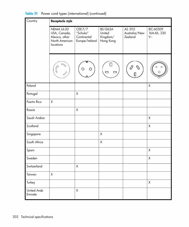
Technical specifications202
Poland X
Portugal X
Puerto Rico X
Russia X
Saudi Arabia X
Scotland X
Singapore X
South Africa X
Spain X
Sweden X
Switzerland X
Taiwan X
Turkey X
United Arab Emirate
X
Table 51 Power cord types (international) (continued)
Country Receptacle style
NEMA L6-20USA, Canada, Mexico, other North American locations
CEE-7/7“Schuko”Continental Europe/Ireland
BS-1363AUnited Kingdom/ Hong Kong
AS 3112Australia/New Zealand
IEC-6030916A-6h, 230 V~

SAN Director installation guide 203
United Kingdom / Ireland
X
United States X X
Venezuela X
Yugoslavia X
Table 51 Power cord types (international) (continued)
Country Receptacle style
NEMA L6-20USA, Canada, Mexico, other North American locations
CEE-7/7“Schuko”Continental Europe/Ireland
BS-1363AUnited Kingdom/ Hong Kong
AS 3112Australia/New Zealand
IEC-6030916A-6h, 230 V~

Technical specifications204
Environmental requirementsTable 52 lists the environmental operating ranges for the 4/256 SAN Director. The requirements for non-operating conditions are also provided for acceptable storage and transportation environments.
NOTE: The 10° to 40° Celsius range applies to the ambient air temperature at the air intake vents on the nonport side of the switch.
The temperature inside the switch can be up to 75° Celsius during switch operation. If the internal temperature range exceeds the operating ranges of the components, the LEDs, error messages, and Fabric Watch alerts will indicate a problem. Use the tempShow command or Fabric Watch commands to view temperature status.
Thermal policyAt 32° Celsius or lower, fans operate at a low speed. When the chassis temperature reaches 33° Celsius, fan speed increases to high. If any blade within the chassis reaches 60° Celsius, the fan speed increases to high. If any blade reaches 65° Celsius, the blade is powered down.
Table 52 Environmental requirements
Condition Acceptable range during operation Acceptable range during Nonoperation
Ambient temperature 10° to 40° Celsius outside switch(50° to 104° Farenheit)
-40° to +70° Celsius outside switch(-40° to 158° Farenheit)
Humidity 20% to 85% RH noncondensing, at 40° Celsius, with maximum gradient of 10% per hour
10% to 93% RH noncondensing, at 70° Celsius
Altitude Up to 3 km (10,000 ft.)above sea level
0 to 12 km (40,000 ft.)above sea level
Shock 20G, 11ms duration, half-sine wave 33G, 11ms duration, half-sine wave
Vibration 1G p-p, 5-500 Hz at 1.0 octave/minute
2.4G p-p, 5-500 Hz at 1.0 octave/minute
Air flow 350 cu. ft./min.(0.00059 cu. meter/hr)
None required.
Heat dissipation 720 Watts or 2457 BTU (Eight FC4-32 blades and two CP4 cards)
Not applicable.

SAN Director installation guide 205
General specificationsThe 4/256 SAN Director is compliant with United States and international safety and Electromagnetic Compatibility (EMC) standards. Table 53 lists the general specifications for the 4/256 SAN Director.
Table 53 General specifications
Specification Description
Configurable port types F_Port, FL_Port, E_Port, EX_Port, and VEX_Port
EMC (electromagnetic compatibility)
Emissions:An operating 4/256 SAN Director conforms to the emissions requirements specified by the following regulations:
• FCC Rules & Regulations, Part 15 subpart B, Class A
• CISPR22 Class A
• EN55022 Class A
• VCCI Class A ITE
• AS/NZS 3548 Class A
• ICES-003 Class A
Immunity:
• IEC 61000-4-2 Severity Level 3 for Electrostatic Discharge
• IEC 61000-4-3 Severity Level 3 for Radiated Fields
• IEC 61000-4-4 Severity Level 3 for Fast Transients
• IEC 61000-4-5 Severity Level 3 for Surge Voltage
• IEC 61000-4-6 Conducted Emissions
• IEC 61000-4-11 Voltage Variations
System architecture Nonblocking shared memory
System processor IPowerPC 440GX, 800MHz CPU
ANSI fibre channel protocol FC-PH (Fibre Channel Physical and Signalling Interface standard)
Modes of operation Fibre Channel Class 2, Class 3, and Class F
Fabric initialization Complies with FC-SW 5.0

Technical specifications206
Data transmission rangesTable 54 provides the data transmission ranges for different cable types and port speeds.
FC-IP (IP over fibre channel) Complies with FC-IP 2.3 of the FCA profile
Aggregate I/O bandwidth 2048 Gb/sec, end-to-end
Port to port latency Less than 2 microseconds with no contention (destination port is free)
Routing capacity A minimum aggregate routing capacity of four million frames per second (for Class 2, Class 3, and Class F frames in a 64-port switch)
Table 53 General specifications (continued)
Specification Description
Table 54 Laser Data transmission ranges
Port Speed
Cable size(microns)
Short wavelength Long wavelength Extended long wavelength
1 Gb/sec 50 1,640 feet (500 meters) NA NA
62.5 984 feet (300 meters) NA NA
9 NA 6.2 miles (10 km) 49.7 miles (80 km)
2 Gb/sec 50 1641 feet (500 meters) NA NA
62.5 984 feet (300 meters) NA NA
9 NA 6.2 miles (10 km) without an Extended Fabrics license; 50 to 100 km with an Extended Fabrics license
49.7 miles (80 km)
4 Gb/sec 50 500 feet (155 meters) NA NA
62.5 300 feet (80 meters NA NA
9 NA 6.2 miles (10 km) 49.7 miles (80 km)

SAN Director installation guide 207
Fibre Channel port specificationsThe fibre channel ports in the 4/256 SAN Director support full duplex link speeds at 4.25, 2.125 or 1.0625 Gb/sec inbound and outbound, automatically negotiating to the highest common speed of all devices connected to the port. Each port has a SerDes (serializer/deserializer) that accepts 10-bit wide parallel data and serializes it into a high-speed serial stream. The parallel data is expected to be “8B/10B” encoded data or equivalent.
The ports are compatible with optical SWL (short wavelength: 780-850 nm), optical LWL (long wavelength: 1270-1350 nm), and Extended Long Wavelength (ELWL) laser transmitter SFPs (small form factor pluggable media) and SFP-compatible cables. The strength of the signal is determined by the type of SFP in use.
The ports are universal and self-configuring, capable of becoming F_Ports (fabric ports), FL_Ports (fabric loop enabled), or E_Ports (expansion ports).
The ports meet all required safety standards. For a listing of these standards, refer to ”Regulatory compliance notices” on page 183.
CP card specificationsCP card specifications include:
• Memory specifications, page 207
• Battery specifications, page 208
• Terminal serial port specifications, page 177
• Modem serial port specifications, page 209
Memory specificationsEach CP card has the following memory:
• Main memory: 512 MB SDRAM (72 bits wide)
• Flash memory:
• User flash: 16 MB of 16-bit wide memory, stored in two 8-MB banks
• Compact flash: 1 GB, partitioned in two 512-MB sections
• Boot flash: 512 KB of 8-bit for system boot
The centralized memory maximizes the overall switch throughput by guaranteeing full transmit and receive bandwidth to all fibre channel ports at all times.

Technical specifications208
Battery specificationsThe CP card has a lithium carbon-monoflouride coin cell battery type Rayovac BR1225, specification 3.0 volt, 50 mAh.
WARNING! Do not attempt to replace the real time clock (RTC) battery on the CP card. There is danger of explosion if the battery is incorrectly replaced or disposed of. Contact HP Technical Support if the real time clock begins to lose time.
Serial port specificationsEach CP card provides a three-wire terminal serial port (labeled 10101) that has a “DB-9” male connector and an RS-232 signal subset.
NOTE: To provide dust and ESD protection, keep the cover on the serial port whenever the port is not in use. The terminal serial port is intended primarily for use during the initial setting of the IP address and for service purposes
The serial port can be used to connect to a computer workstation or terminal without connecting to the fabric. The terminal device should be configured to 9600 baud, 8 data bits, no parity, 1 stop bit, with no flow control.
A 10 ft. (3.0 m) serial cable is provided with the switch; it can be converted from a DB-9 serial cable to an RJ-45-style serial cable by removing the adapter on the end of the cable.
The terminal serial port requires a straight-through serial cable with a female 9-pin subminiature-D connector. Use the pinouts listed in Table 55.
Table 55 Serial port pinouts
PIN Signal Description
1 ---- ----
2 TxData Transmit Data
3 RxData Receive Data
4 ---- ----
5 GND Logic Ground
6 ---- ----

SAN Director installation guide 209
Modem serial port specificationsEach CP card has a modem serial port (labeled RS-232) with a fully RS-232 compliant DB-9 connector.
The modem port can be used for attaching a modem to each CP card. The 4/256 SAN Director detects modems only during the power-on or reboot sequences, and automatically initializes them for operation. If modems are connected to an operating switch, a power on/off cycle, reboot, or fast reboot is required to detect the modem(s).
If both modems are connected to the telephone line by a “Y” cable, the active CP card answers on the first ring; if the active CP card fails to answer, the standby CP card answers on the seventh ring.
The pinouts for the modem serial port are shown in Table 56.
7 ---- ----
8 ---- ----
9 ---- ----
Table 55 Serial port pinouts (continued)
PIN Signal Description
Table 56 Modem serial port pinouts
PIN Signal Description
1 DCD Data Carrier Detect
2 RxData Receive Data
3 TxData Transmit Data
4 DTR Data Term Ready
5 GND Logic Ground
6 DSR Data Set Ready
7 RTS Request to Send
8 CTS Clear to Send
9 RI Ring Indicator

Technical specifications210
Regulatory certificationsThe 4/256 SAN Director is certified for the safety and EMC (electromagnetic compatibility) specifications listed in Table 57.
Table 57 4/256 SAN Director regulatory certifications
Country Safety specification EMC specification
Argentina IRAM NA
Australia/ New Zealand NA AS/NZS 3548 Class A
Canada CSA 22.2 No. 60950 ICES-003 Class A
European Community EN60950TUVNEMKO
EN55022 Level AEN55024
International IEC 60950 CISPR22 Class A
Japan IEC 60950 VCCI V-3/2000.04, Class A
Korea NA RRL
Norway IEC 60950(NEMKO CB Report)
NA
Russian Federation GOST GOST
United States UL 60950 FCC Part 15, Subpart B, (CFR title 47) Class A

SAN Director installation guide 211
B Port blade and CP card support notesThis chapter provides the following information:
• CP card compatibility, page 212• Port blade compatibility, page 213• Supported port blade installation overview, page 213• Installing port blade procedures, page 217• Validating the installation, page 218• Troubleshooting the installation, page 218

Port blade and CP card support notes212
CP card compatibilityInstalled CP cards determine the Director type:
• If CP1 blades are installed, the Director is an HP StorageWorks Core Switch 2/64.• If CP2 blades are installed, the Director is a HP StorageWorks SAN Director 2/128.• If CP4 blades are installed, the Director is a HP StorageWorks 4/256 SAN Director.
NOTE: Mixed CP cards are not supported on a single chassis. HP requires that each CP (primary and secondary partition) maintain the same firmware version.
Table 58 provides a list of all configurations and port blades supported by the CP cards. Table 58 CPs and chassisConfig mode
CP Type chassisConfig Mode Number of Domains
Supported Port Blades
CP1 chassisConfig is not supported.
2 FC-16
CP2 chassisConfig 1 1 FC2-16
FC4-16
chassisConfig 2 2 FC2-16
chassisConfig 3 This chassisConfig mode is no longer supported.
chassisConfig 4 This chassisConfig mode is no longer supported.
CP4 chassisConfig 1 1 FC2-16
FC4-16
chassisConfig 5 1 FC4-16
FC4-32
FC4-48
FR4-18i (up to two)
FC4-16IP (up to four)
Note: Up to a maximum of four AP blades (FR4-18i, FC4-16IP)

SAN Director installation guide 213
Port blade compatibilityThis section provides information on supported blades for each Director.
Supported port blade installation overviewThe following high-level blade installation procedures are supported. For more information on chassisConfig mode see ”Chassis configuration setting” on page 214.
Adding FC2-16 port blades to a 4/256 SAN DirectorCP4 control processor blades support the following port blades:
• FC2-16 and FC4-16 port blades in chassisConfig mode 1• FC4-16, FC4-32, or FC4-48 port blades in chassisConfig mode
NOTE: Do not change the chassisConfig mode, as doing so is disruptive.
• The FC2-16 blades can be used in a 4/256 SAN Director, when only FC4-16 blades are used.• This procedure is nondisruptive to I/O across the Director, except when individual port blades
are being replaced or if the chassisConfig mode is changed.
Adding B-Series MP Router (FR4-18i) port blades to a 4/256 SAN DirectorPrior to installation verify the following requirements:
• Four power supplies are required.• Chassis Config mode 5 is required.• Up to two B-Series MP Router port blades can be installed to a single chassis.
Table 59 Blades supported by each Director
Director Port Blades
FC-16 FC2-16 FC4-16 FC4-32 FC4-48 FC4-18i FC4-16IP
Core Switch 2/64 Supported NA NA NA NA NA NA
SAN Director 2/128 chassisConfig mode 3 and 4
chassisConfig mode 1, 2, 3, and 4
chassisConfig mode 1
NA NA NA NA
4/256 SAN Director NA chassisConfig mode 1
chassisConfig mode 1 and 5
chassisConfig mode 5
chassisConfig mode 5
chassisConfig mode 5
chassisConfig mode 5

Port blade and CP card support notes214
Adding 4/16IP SAN Director (FC4-16IP) port blades to a 4/256 SAN Director
Prior to installation verify the following requirements:
• Four Power Supplies are required.• Chassis Config mode 5 is required.• Up to four FC4-16IP blades can be installed to a single chassis.
NOTE: A maximum of four Intelligent blades can be used in a single 4/256 SAN Director chassis: combination of up to two FR4-18i and up to four FC4-16IP blades.
Chassis configuration settingWhen migrating a Director with two domains (two logical switches) to a 4/256 SAN Director, the result will be a Director with only one domain. Depending on your configuration, this may change the topology of the fabric and should be taken into consideration when planning your installation. The 4/256 SAN Director supports chassis configuration options 1 or 5 only.
Use the chassisConfig command to change the chassis configuration. The valid options are:
• Option 1—One (up to) 128-port logical switchThis chassis mode supports CP4 control processor blades managing FC2-16 and FC4-16 port blades.
• Option 5—One (up to) 384-port logical switchThis chassis mode supports CP4 control processor blades managing FC4-16, FC4-32, and FC4-48 port blades, and the FR4-18i and FC4-16IP intelligent blades.
Power requirementsAlthough the 4/256 SAN Director can support four power supplies, only two power supplies are required to function in redundant power mode. The power supplies must be in an odd and an even slot (slot 1 and 2, or slot 1 and 4, or slot 2 and 3, or slot 3 and 4).
A 4/256 SAN Director populated with either the B-Series MP Router (FR4-18i) or the FC4-16IP blades (FC4-16IP) must operate with four functional power supplies.
A fully populated 4/256 SAN Director with no Intelligent blades can function with the power supplied with two power supplies, so there is no need to add or replace any power supplies in the chassis.

SAN Director installation guide 215
Preparing to add new port bladesThis section provides information on how to prepare for the installation.
NOTE: The Core Switch 2/64 is supported only up to Fabric OS v5.0.x.
Upgrading to the latest Fabric OS versionThe 4/256 SAN Director must be upgraded to Fabric OS 5.2.x (or later) prior to the installation process. Use the firmwareDownload command to upgrade the Director, and the firmwareShow command to verify that both Director CPs (primary and secondary partitions) are upgraded to Fabric OS 5.2.x.
In order to first upgrade the firmware on the SAN Director 2/128 to Fabric OS 5.2.x, you must start with either Fabric OS 5.0.1 or 5.1.x. If your Director operates with a firmware version prior to Fabric OS 5.0.1, you must install either 5.0.1 or 5.1.x before upgrading to Fabric OS 5.2.x.
You should also verify that all the switches in the fabric are updated to the latest Fabric OS version supported on that switch and supported in a fabric running that version. This will provide the maximum level of compatibility between the switches in the fabric and the Director.
Always perform a configUpload on each switch before performing any firmware upgrade. For a downgrade, the configuration files will have been preserved for that version of firmware.
See the HP StorageWorks Fabric OS administrator guide for more information on the firmwareDownload, configUpload, and firmwareShow commands.
NOTE: Before installing new blades, upgrade firmware on the Director to the version necessary for the blades. Upgrade to Fabric OS 5.1.x or 5.2.x before installing the B-Series MP Router (FR4-18i) Blade and to 5.2.x before installing the 4/16IP SAN Director (FC4-16IP) Blade.

Port blade and CP card support notes216
Backing up the Director configuration and obtaining a SAN profileCompleting the steps below to document and backup the current configuration reduces the process time for blade installation and Director changes, and can help should any complication be encountered. Save the configuration settings in the forms provided in ”4/256 SAN Director configuration forms” on page 219.
NOTE: Capture the output of all commands supported by your Telnet program for reference.
1. Establish a telnet session and log in to the Director as admin. 2. Display the switch information by running the switchShow command and save the Domain ID,
switch name, and devices connected on the configuration tables. The configuration tables are available in ”4/256 SAN Director configuration forms” on page 219.
3. Display the current switch ports settings by running the command portCfgShow and record the configuration of the switch ports in the configuration tables.
4. Display the total number of devices in the switch local Name Server database using the nsShow command and save the number of devices in the configuration table.
5. Display the total number of devices in the switch Global Name Server Database using the nsAllShow command and save the total number of devices in the configuration table.
6. Display the total number of domains in the fabric using the fabricShow command and save the total number of domains in the configuration table. If you are migrating a dual-domain Director to a single domain Director this value will be one domain lower after the installation.
7. Upload the switch configuration settings to an FTP server using the configUpload command. 8. Run the supportSave command to provide a baseline for support, if needed.
Verifying a safe work spaceRemoving CP cards and port blades requires adequate work space in front of the Director. Verify that you have adequate space in front of the chassis to safely pull and replace the blades.
Verify that the chassis is properly grounded. HP recommends that you wear a grounding strap whenever you come into physical contact with the Director.
Labeling all the cablesLabel the Fibre Channel, Ethernet, Serial Console, and modem cables, using industry best practices for easy reconnection when the switch is migrated.

SAN Director installation guide 217
Installing port blade proceduresThis section provides procedures for installing port blades.
Adding FC2-16 blades to a 4/256 SAN DirectorAdding FC2-16 port blades to a Director requires the installation of up to eight port blades in the chassis. The chassis must be configured in chassisConfig option 1.
If you are using chassisConfig mode 1 you can add FC2-16 blades with minimal disruption. If you are using chassisConfig mode 5, you must change to mode 1 prior to executing this procedure. Changing the chassisConfig mode requires a reboot and is disruptive.
To add FC2-16 port blades to a 4/256 SAN Director:
1. Telnet into the 4/256 SAN Director as admin.2. Verify that the Director is upgraded to Fabric OS v5.0.1 (or higher) on both CPs by running the
firmwareShow command. Both CPs, primary and secondary partitions, should be at Fabric OS 5.0.1 (or higher). Use the firmwareDownload command to upgrade the firmware if required.
3. Create a snapshot of the Director setup using the supportSave command. This command creates a baseline for support if problems arise. This command may take up to a half an hour to complete.
4. Verify that your switch is in chassisConfig option 1. Enter the chassisConfig command without operands to view the current mode.
5. Install the FC2-16 port blades, one at a time, as follows:a. Verify that your wrist strap is grounded to the chassis of the 4/256 SAN Director. Adjust the
wristband so that there are no gaps between the band and your skin.b. Secure the FC2-16 blade in place. Make sure that you unscrew the latches and that they are
open when you push the blade into the chassis.c. Connect the Fibre Channel cables to the new blade.
6. Verify that all your blades are detected by the switch, complete POST, and are enabled using the slotShow command. If a blade faults or hangs in POST, contact HP.
7. Validate the installation by running the following commands: nsShow, nsAllShow, and fabricShow. All of your connected servers, storage, and switches should be present in the output of these commands. If there is a discrepancy, it is possible that a device or switch is not
Table 60 FC2-16 port blade summary
Prerequisites Description
Time Required 1 hour
Level of Disruption This procedure is nondisruptive to I/O across the Director, unless the chassisConfig mode is changed.
Parts Required Up to eight FC2-16 blades

Port blade and CP card support notes218
able to connect to the fabric and further troubleshooting is necessary. For more information see ”Validating the installation”.This completes FC2-16 port blade installation in a 4/256 SAN Director.
Validating the installationThis section provides information on validating the installation of port blades.
Validate the installation by running the following commands: nsShow, nsAllShow, and fabricShow.
All of your connected servers, storage, and switches should be present in the output of these commands. If there is a discrepancy, it is possible that a device or switch is not able to connect to the fabric and further troubleshooting is necessary.
nsShow Displays all devices directly connected to the switch that have logged into the Name Server. Make sure that the number of attached devices after the installation is exactly the same as the number of attached devices prior to the installation.
nsAllShow Displays all devices connected to a fabric. Make sure that the number of attached devices after the installation is exactly the same as the number of attached devices prior to the installation.
fabricShow Displays all switches in a fabric. Make sure that the number of switches in the fabric after the installation is exactly the same as the number of attached devices prior to the installation. There may be one less domain in your fabric if during the installation you went from dual domain to a single domain in your Director.
Troubleshooting the installationIf there is a discrepancy in the number of switches or attached devices in the fabric after the installation, it may be due to a fabric segmentation or a device that failed to log in. For assistance, see the following:
• Troubleshooting chapter in the HP StorageWorks Fabric OS administrator guide for basic troubleshooting steps.
• Run the supportSave command to provide a comparison from earlier execution of this command.

SAN Director installation guide 219
4/256 SAN Director configuration formsThis section provides forms for recording configuration information prior to the installation process. The port setting tables can be used on 16, 32, and 48 port blades to record configuration information. Table 61 Director configuration settings
Director configuration settings
CP 0 IP address
CP 1 IP address
Gateway address
chassisConfig Option
Slot 5 Slot 6
Serial cable tag: Serial cable tag:
Ethernet cable tag: Ethernet cable tag:
Modem cable tag: Modem cable tag:
Variables Logical Switch 0
Domain ID
Switch Name
Ethernet IP Address
Ethernet Subnet Mask
Total number of local devices (nsShow)
Total number of devices in fabric(nsAllShow)
Total number of switches in fabric (fabricShow)

Port blade and CP card support notes220
Table 62 Director FC port configuration settings
Port Numbers
Slot # ___ 0 1 2 3 4 5 6 7 8 9 10 11 12 13 14 15
Deviceconnected
Speed
Trunk
LongDistance
VC Link Init
LockedL_Port
LockedG_Port
Disable E-Port
MCastloopback
Delay FLOGI
ISL R_RDYmode
Persistentdisable

SAN Director installation guide 221
Table 63 Director FC Port configuration settings
Port Numbers
Slot # ___ 16 17 18 19 20 21 22 23 24 25 26 27 28 29 30 31
Deviceconnected
Speed
Trunk
LongDistance
VC Link Init
LockedL_Port
LockedG_Port
Disable E-Port
MCastloopback
Delay FLOGI
ISL R_RDYmode
Persistentdisable
Table 64 FC port configuration setting
Port numbers
Slot # ___ 32 33 34 35 36 37 38 39 40 41 42 43 44 45 46 47
Deviceconnected
Speed

Port blade and CP card support notes222
Trunk
LongDistance
VC Link Init
LockedL_Port
LockedG_Port
Disable E-Port
MCastloopback
Delay FLOGI
ISL R_RDYmode
Persistentdisable
Table 64 FC port configuration setting
Port numbers
Slot # ___ 32 33 34 35 36 37 38 39 40 41 42 43 44 45 46 47

SAN Director installation guide 223
C Regulatory compliance and safety notices
Regulatory complianceFederal Communications Commission notice for Class A equipment
This equipment has been tested and found to comply with the limits for a Class A digital device, pursuant to Part 15 of the FCC Rules. These limits are designed to provide reasonable protection against harmful interference when the equipment is operated in a commercial environment. This equipment generates, uses and can radiate radio frequency energy and, if not installed and used in accordance with the instruction manual, may cause harmful interference to radio communications. Operation of this equipment in a residential area is likely to cause harmful interference, in which case the user will be required to correct the interference at his own expense. The end user of this product should be aware that any changes or modifications made to this equipment without the approval of Hewlett-Packard could result in the product not meeting the Class A limits, in which case the FCC could void the user's authority to operate the equipment.
HP StorageWorks 4/256 SAN Director Regulatory Model Number: HSTNM-N006
Declaration of conformity for products marked with the FCC logo, United States onlyThis device complies with Part 15 of the FCC Rules. Operation is subject to the following two conditions: (1) this device may not cause harmful interference, and (2) this device must accept any interference received, including interference that may cause undesired operation.
For questions regarding your product, visit http://www.hp.com.
For questions regarding this FCC declaration, contact us by mail or telephone:
• Hewlett-Packard CompanyP.O. Box 692000, Mailstop 510101Houston, Texas 77269-2000
• 1-281-514-3333
To identify this product, refer to the part, Regulatory Model Number, or product number found on the product.
ModificationsThe FCC requires the user to be notified that any changes or modifications made to this device that are not expressly approved by Hewlett-Packard Company may void the user's authority to operate the equipment.
CablesConnections to this device must be made with shielded cables with metallic RFI/EMI connector hoods in order to maintain compliance with FCC Rules and Regulations.

Regulatory compliance and safety notices224
Regulatory compliance identification numbersFor the purpose of regulatory compliance certifications and identification, your product has been assigned a unique Regulatory Model Number. The RMN can be found on the product nameplate label, along with all required approval markings and information. When requesting compliance information for this product, always refer to this RMN. The Regulatory Model Number should not be confused with the marketing name or model number of the product.
HP StorageWorks 4/256 SAN Director Regulatory Model Number is HSTNM-N006.
Laser deviceAll HP systems equipped with a laser device comply with safety standards, including International Electrotechnical Commission (IEC) 825. With specific regard to the laser, the equipment complies with laser product performance standards set by government agencies as a Class 1 laser product. The product does not emit hazardous light.
Laser safety warning
WARNING! To reduce the risk of exposure to hazardous radiation:• Do not try to open the laser device enclosure. There are no user-serviceable components inside.• Do not operate controls, make adjustments, or perform procedures to the laser device other than
those specified herein.• Allow only HP authorized service technicians to repair the laser device.
Certification and classification informationThis product contains a laser internal to the fiber optic (FO) transceiver for connection to the Fibre Channel communications port.
In the USA, the FO transceiver is certified as a Class 1 laser product conforming to the requirements contained in the Department of Health and Human Services (DHHS) regulation 21 CFR, Subchapter J. A label on the plastic FO transceiver housing indicates the certification.
Outside the USA, the FO transceiver is certified as a Class 1 laser product conforming to the requirements contained in IEC 825-1:1993 and EN 60825-1:1994, including Amendment 11:1996 and Amendment 2:2001.

SAN Director installation guide 225
Laser product labelThe optional label in Figure 41 or equivalent may be located on the surface of the HP supplied laser device.
Figure 41 Class 1 laser product label
International notices and statementsCanadian notice (avis Canadien)Class A equipment
This Class A digital apparatus meets all requirements of the Canadian Interference-Causing Equipment Regulations.
Cet appareil numérique de la classe A respecte toutes les exigences du Règlement sur le matériel brouilleur du Canada.
European Union noticeProducts bearing the CE marking comply with the EMC Directive (89/336/EEC) and the Low Voltage Directive (73/23/EEC) issued by the Commission of the European Community and if this product has telecommunication functionality, the R&TTE Directive (1999/5/EC).
Compliance with these directives implies conformity to the following European Norms (in parentheses are the equivalent international standards and regulations):
• EN55022 (CISPR 22) - Electromagnetic Interference• EN55024 (IEC61000-4-2, IEC61000-4-3, IEC61000-4- 4, IEC61000-4-5, IEC61000-4-6,
IEC61000-4-8, IEC61000-4-11) - Electromagnetic Immunity• Power Quality:
• EN61000-3-2 (IEC61000-3-2) - Power Line Harmonics• EN61000-3-3 (IEC61000-3-3) - Power Line Flicker
• EN60950 (IEC60950) - Product Safety• Also approved under UL 60950/CSA C22.2 No. 60950-00, Safety of Information Technology
Equipment.
This optional label indicates that the product is classified as a CLASS 1 LASER PRODUCT. This label may appear on the laser device installed in your product.

Regulatory compliance and safety notices226
BSMI notice
Japanese notice
Korean notices

SAN Director installation guide 227
SafetyThe following sections summarize ways to maintain a safe operating environment for the Director.
Electrostatic discharge recommendationsTo prevent damaging the system, be aware of the precautions you need to follow when setting up the system or handling parts. A discharge of static electricity from a finger or other conductor may damage system boards or other static-sensitive devices. This type of damage may reduce the life expectancy of the device.
To prevent electrostatic damage, observe the following precautions:
• Avoid hand contact by transporting and storing products in static-safe containers.• Keep electrostatic-sensitive parts in their containers until they arrive at static-free workstations.• Place parts on a grounded surface before removing them from their containers.• Avoid touching pins, leads, or circuitry.• Always make sure you are properly grounded when touching a static-sensitive component or
assembly.
Grounding methodsThere are several methods for grounding. Use one or more of the following methods when handling or installing electrostatic-sensitive parts:
• Use a wrist strap connected by a ground cord to a grounded workstation or computer chassis. Wrist straps are flexible straps with a minimum of 1 megohm ± 10 percent resistance in the ground cords. To provide proper ground, wear the strap snug against the skin.
• Use heel straps, toe straps, or boot straps at standing workstations. Wear the straps on both feet when standing on conductive floors or dissipating floor mats.
• Use conductive field service tools.• Use a portable field service kit with a folding static-dissipating work mat.If you do not have any
of the suggested equipment for proper grounding, have an HP authorized reseller install the part.
NOTE: For more information on static electricity, or for assistance with product installation, contact your HP authorized reseller.

Regulatory compliance and safety notices228
Battery replacement noticeYour switch is equipped with a lithium manganese dioxide, a vanadium pentoxide, or an alkaline internal battery or battery pack. There is a danger of explosion and risk of personal injury if the battery is incorrectly replaced or mistreated. Replacement is to be done by an HP authorized service provider using the HP spare part designated for this product. For more information about battery replacement or proper disposal, contact an HP authorized reseller or HP authorized service provider.
WARNING! Your switch contains an internal lithium manganese dioxide, a vanadium pentoxide, or an alkaline battery pack. There is risk of fire and burns if the battery pack is not properly handled. To reduce the risk of personal injury:• Do not attempt to recharge the battery.• Do not expose to temperatures higher than 60°C.• Do not disassemble, crush, puncture, short external contacts, or dispose of in fire or water.• Replace only with the HP spare part designated for this product.
For more information about battery replacement or proper disposal, contact an HP authorized reseller or service provider.
Taiwan battery recycling notice
Batteries, battery packs, and accumulators should not be disposed of together with the general household waste. To forward them to recycling or proper disposal, please use the public collection system or return them to HP, an authorized HP Partner, or their agents.
The Taiwan EPA requires dry battery manufacturing or importing firms in accordance with Article 15 of the Waste Disposal Act to indicate the recovery marks on the batteries used in sales, giveaway or promotion. Contact a qualified Taiwanese recycler for proper battery disposal.

SAN Director installation guide 229
Power cordsThe power cord set must meet the requirements for use in the country where the product was purchased. If the product is to be used in another country, purchase a power cord that is approved for use in that country.
The power cord must be rated for the product and for the voltage and current marked on the product electrical ratings label. The voltage and current rating of the cord should be greater than the voltage and current rating marked on the product. In addition, the diameter of the wire must be a minimum of 1.00 mm2 or 18 AWG, and the length of the cord must be between 1.8 m (6 ft) and 3.6 m (12 ft). If you have questions about the type of power cord to use, contact an HP authorized service provider.
NOTE: Route power cords so that they will not be walked on and cannot be pinched by items placed upon or against them. Pay particular attention to the plug, electrical outlet, and the point where the cords exit from the product.
Japanese power cord notice
Waste Electrical and Electronic Equipment directiveEnglish noticeWaste Electrical and Electronic Equipment (WEEE) Recycling Notice
Disposal of waste equipment by users in private household in the European UnionThis symbol on the product or on its packaging indicates that this product must not be disposed of with your other household waste. Instead, it is your responsibility to dispose of your waste equipment by handing it over to a designated collection point for recycling of waste electrical and electronic equipment. The separate collection and recycling of your waste equipment at the time of disposal will help to conserve natural resources and ensure that it is recycled in a manner that protects human health and the environment. For more information about where you can drop off your waste equipment for recycling, please
contact your local city office, your household waste disposal service, or the shop where you purchased the product.

Regulatory compliance and safety notices230
Czechoslovakian notice
Danish notice Bortskaffelse af affald fra husstande i den Europæiske Union
Hvis produktet eller dets emballage er forsynet med dette symbol, angiver det,at produktet ikke må bortskaffes med andet almindeligt husholdningsaffald. I stedet er det dit ansvar at bortskaffe kasseret udstyr ved at aflevere det på den kommunale genbrugsstation, der forestår genvinding af kasseret elektrisk og elektronisk udstyr. Den centrale modtagelse og genvinding af kasseret udstyr i forbindelse med bortskaffelsen bidrager til bevarelse af naturlige ressourcer
og sikrer, at udstyret genvindes på en måde, der beskytter både mennesker og miljø. Yderligere oplysninger om, hvor du kan aflevere kasseret udstyr til genvinding, kan du få hos kommunen, den lokale genbrugsstation eller i den butik, hvor du købte produktet.

SAN Director installation guide 231
Estonian notice
Finnish notice
French notice
Seadmete jäätmete kõrvaldamine eramajapidamistes Euroopa Liidus
See tootel või selle pakendil olev sümbol näitab, et kõnealust toodet ei tohi
koos teiste majapidamisjäätmetega kõrvaldada. Teie kohus on oma
seadmete jäätmed kõrvaldada, viies need elektri- ja elektroonikaseadmete
jäätmete ringlussevõtmiseks selleks ettenähtud kogumispunkti. Seadmete
jäätmete eraldi kogumine ja ringlussevõtmine kõrvaldamise ajal aitab kaitsta
loodusvarasid ning tagada, et ringlussevõtmine toimub viisil, mis kaitseb inimeste tervist
ning keskkonda. Lisateabe saamiseks selle kohta, kuhu oma seadmete jäätmed
ringlussevõtmiseks viia, võtke palun ühendust oma kohaliku linnakantselei,
majapidamisjäätmete kõrvaldamise teenistuse või kauplusega, kust Te toote ostsite.
Laitteiden hävittäminen kotitalouksissa Euroopan unionin alueella
Jos tuotteessa tai sen pakkauksessa on tämä merkki, tuotetta ei saa hävittää kotitalousjätteiden mukana. Tällöin hävitettävä laite on toimitettava sähkölaitteiden ja elektronisten laitteiden kierrätyspisteeseen. Hävitettävien laitteiden erillinen käsittely ja kierrätys auttavat säästämään luonnonvaroja ja varmistamaan, että laite kierrätetään tavalla, joka estää terveyshaitat ja suojelee luontoa. Lisätietoja paikoista, joihin hävitettävät laitteet voi toimittaa kierrätettäväksi, saa ottamalla
yhteyttä jätehuoltoon tai liikkeeseen, josta tuote on ostettu.
Élimination des appareils mis au rebut par les ménages dans l'Union européenne
Le symbole apposé sur ce produit ou sur son emballage indique que ce produit ne doit pas être jeté avec les déchets ménagers ordinaires. Il est de votre responsabilité de mettre au rebut vos appareils en les déposant dans les centres de collecte publique désignés pour le recyclage des équipements électriques et électroniques. La collecte et le recyclage de vos appareils mis au rebut indépendamment du reste des déchets contribue à la préservation des ressources
naturelles et garantit que ces appareils seront recyclés dans le respect de la santé humaine et de l'environnement. Pour obtenir plus d'informations sur les centres de collecte et de recyclage des appareils mis au rebut, veuillez contacter les autorités locales de votre région, les services de collecte des ordures ménagères ou le magasin dans lequel vous avez acheté ce produit.

Regulatory compliance and safety notices232
German notice
Greek notice
Entsorgung von Altgeräten aus privaten Haushalten in der EU
Das Symbol auf dem Produkt oder seiner Verpackung weist darauf hin, dass das Produkt nicht über den normalen Hausmüll entsorgt werden darf. Benutzer sind verpflichtet, die Altgeräte an einer Rücknahmestelle für Elektro- und Elektronik-Altgeräte abzugeben. Die getrennte Sammlung und ordnungsgemäße Entsorgung Ihrer Altgeräte trägt zur Erhaltung der natürlichen Ressourcen bei und garantiert eine Wiederverwertung, die die Gesundheit des Menschen und
die Umwelt schützt. Informationen dazu, wo Sie Rücknahmestellen für Ihre Altgeräte finden, erhalten Sie bei Ihrer Stadtverwaltung, den örtlichen Müllentsorgungsbetrieben oder im Geschäft, in dem Sie das Gerät erworben haben.
. ,
.
.
,
,
.

SAN Director installation guide 233
Hungarian notice
Italian notice
Készülékek magánháztartásban történ selejtezése az Európai Unió területén
A készüléken, illetve a készülék csomagolásán látható azonos szimbólum annak
jelzésére szolgál, hogy a készülék a selejtezés során az egyéb háztartási
hulladéktól eltér módon kezelend . A vásárló a hulladékká vált készüléket köteles
a kijelölt gy jt helyre szállítani az elektromos és elektronikai készülékek
újrahasznosítása céljából. A hulladékká vált készülékek selejtezéskori begy jtése
és újrahasznosítása hozzájárul a természeti er források meg rzéséhez, valamint biztosítja
a selejtezett termékek környezetre és emberi egészségre nézve biztonságos feldolgozását.
A begy jtés pontos helyér l b vebb tájékoztatást a lakhelye szerint illetékes önkormányzattól,
az illetékes szemételtakarító vállalattól, illetve a terméket elárusító helyen kaphat.
Smaltimento delle apparecchiature da parte di privati nel territorio dell'Unione Europea
Questo simbolo presente sul prodotto o sulla sua confezione indica che il prodotto non può essere smaltito insieme ai rifiuti domestici. È responsabilità dell'utente smaltire le apparecchiature consegnandole presso un punto di raccolta designato al riciclo e allo smaltimento di apparecchiature elettriche ed elettroniche. La raccolta differenziata e il corretto riciclo delle apparecchiature da smaltire permette di proteggere la salute degli individui e l'ecosistema. Per ulteriori informazioni relative
ai punti di raccolta delle apparecchiature, contattare l'ente locale per lo smaltimento dei rifiuti, oppure il negozio presso il quale è stato acquistato il prodotto.

Regulatory compliance and safety notices234
Latvian notice
Lihuanian notice
Nolietotu iek rtu izn cin šanas noteikumi lietot jiem Eiropas Savien bas priv taj s m jsaimniec b s
Š ds simbols uz izstr d juma vai uz t iesai ojuma nor da, ka šo
izstr d jumu nedr kst izmest kop ar citiem sadz ves atkritumiem. J s
atbildat par to, lai nolietot s iek rtas tiktu nodotas speci li iek rtotos
punktos, kas paredz ti izmantoto elektrisko un elektronisko iek rtu
sav kšanai otrreiz jai p rstr dei. Atseviš a nolietoto iek rtu sav kšana un
otrreiz j p rstr de pal dz s saglab t dabas resursus un garant s, ka š s iek rtas tiks
otrreiz ji p rstr d tas t d veid , lai pasarg tu vidi un cilv ku vesel bu. Lai uzzin tu, kur
nolietot s iek rtas var izmest otrreiz jai p rstr dei, j v ršas savas dz ves vietas
pašvald b , sadz ves atkritumu sav kšanas dienest vai veikal , kur izstr d jums tika
nopirkts.

SAN Director installation guide 235
Polish notice
Portuguese notice
Pozbywanie si zu ytego sprz tu przez u ytkowników w prywatnych gospodarstwach domowych w Unii Europejskiej
Ten symbol na produkcie lub jego opakowaniu oznacza, e produktu nie wolno
wyrzuca do zwykłych pojemników na mieci. Obowi zkiem u ytkownika jest
przekazanie zu ytego sprz tu do wyznaczonego punktu zbiórki w celu recyklingu
odpadów powstałych ze sprz tu elektrycznego i elektronicznego. Osobna zbiórka
oraz recykling zu ytego sprz tu pomog w ochronie zasobów naturalnych
i zapewni ponowne wprowadzenie go do obiegu w sposób chroni cy zdrowie człowieka
i rodowisko. Aby uzyska wi cej informacji o tym, gdzie mo na przekaza zu yty sprz t do
recyklingu, nale y si skontaktowa z urz dem miasta, zakładem gospodarki odpadami lub
sklepem, w którym zakupiono produkt.
Descarte de Lixo Elétrico na Comunidade Européia
Este símbolo encontrado no produto ou na embalagem indica que o produto não deve ser descartado no lixo doméstico comum. É responsabilidade do cliente descartar o material usado (lixo elétrico), encaminhando-o para um ponto de coleta para reciclagem. A coleta e a reciclagem seletivas desse tipo de lixo ajudarão a conservar as reservas naturais; sendo assim, a reciclagem será feita de uma forma segura, protegendo o ambiente e a saúde das pessoas. Para obter
mais informações sobre locais que reciclam esse tipo de material, entre em contato com o escritório da HP em sua cidade, com o serviço de coleta de lixo ou com a loja em que o produto foi adquirido.

Regulatory compliance and safety notices236
Slovakian notice
Slovenian notice

SAN Director installation guide 237
Spanish notice
Swedish notice
Eliminación de residuos de equipos eléctricos y electrónicos por parte de usuarios particulares en la Unión Europea
Este símbolo en el producto o en su envase indica que no debe eliminarse junto con los desperdicios generales de la casa. Es responsabilidad del usuario eliminar los residuos de este tipo depositándolos en un "punto limpio" para el reciclado de residuos eléctricos y electrónicos. La recogida y el reciclado selectivos de los residuos de aparatos eléctricos en el momento de su eliminación contribuirá a conservar los recursos naturales y a garantizar el reciclado de estos residuos
de forma que se proteja el medio ambiente y la salud. Para obtener más información sobre los puntos de recogida de residuos eléctricos y electrónicos para reciclado, póngase en contacto con su ayuntamiento, con el servicio de eliminación de residuos domésticos o con el establecimiento en el que adquirió el producto.
Bortskaffande av avfallsprodukter från användare i privathushåll inom Europeiska Unionen
Om den här symbolen visas på produkten eller förpackningen betyder det att produkten inte får slängas på samma ställe som hushållssopor. I stället är det ditt ansvar att bortskaffa avfallet genom att överlämna det till ett uppsamlingsställe avsett för återvinning av avfall från elektriska och elektroniska produkter. Separat insamling och återvinning av avfallet hjälper till att spara på våra naturresurser och gör att avfallet återvinns på ett sätt som skyddar människors hälsa och miljön.
Kontakta ditt lokala kommunkontor, din närmsta återvinningsstation för hushållsavfall eller affären där du köpte produkten för att få mer information om var du kan lämna ditt avfall för återvinning.

Regulatory compliance and safety notices238

SAN Director installation guide 239
D Port numbering templatesPrint or copy the templates on the following pages and use them to document your SAN, including the port numbering scheme for your 4/256 SAN Director. For each 16-port blade installed in the Director, cross out the extra 16 ports on the graphical representation of the port blade before you fill in the port numbers.

Port numbering templates240
.
2.017
Link
10/100 Mb/s
Active CP
!
IOIO
IRS
-232Link
10/100 Mb/s
Active CP
!
IOIO
IRS
-232
Slot 1 Slot 2 Slot 3 Slot 4 Slot 5 Slot 6 Slot 7 Slot 8 Slot 9 Slot 10

SAN Director installation guide 241
scale:5/16" = 1"
7
6
5
4
3
2
1
0
56-0000590-01 Rev A
!
FC416IP
7
6
5
4
3
2
1
0
GE
FC
7
6
5
4
3
2
1
0
56-0000590-01 Rev A
!
FC416IP
7
6
5
4
3
2
1
0
GE
FC
7
6
5
4
3
2
1
0
56-0000590-01 Rev A
!
FC416IP
7
6
5
4
3
2
1
0
GE
FC
7
6
5
4
3
2
1
0
56-0000590-01 Rev A
!
FC416IP
7
6
5
4
3
2
1
0
GE
FC
25231a

Port numbering templates242
7
6
5
4
3
2
1
0
GE1
GE0
15
14
13
12
11
10
9
8
56-0000590-01 Rev A
!
FR418i
7
6
5
4
3
2
1
0
GE1
GE0
15
14
13
12
11
10
9
8
56-0000590-01 Rev A
!
FR418i
25232a

SAN Director installation guide 243
GlossaryThis glossary defines terms used in this guide or related to this product and is not a comprehensive glossary of computer terms.
AL_PA Arbitrated loop physical address. A unique 8-bit value assigned during loop initialization to a port in an arbitrated loop.
alias server A fabric software facility that supports multicast group management.
API Application programming interface. A defined protocol that allows applications to interface with a set of services.
AW_TOV Arbitration wait time-out value. The minimum time an arbitrating L_Port waits for a response before beginning loop initialization.
backup FCS switch
Backup fabric configuration server switch. The switch or switches assigned as backup in case the primary FCS switch fails.
bandwidth The total transmission capacity of a cable, link, or system. Usually measured in bps (bits per second). May also refer to the range of transmission frequencies available to a link or system.
broadcast The transmission of data from a single source to all devices in the fabric, regardless of zoning.
buffer-to-buffer flow control
Management of the frame transmission rate in either a point-to-point topology or in an arbitrated loop.
CLI Command line interface. Interface that depends entirely on the use of commands, such as through telnet or SNMP, and does not involve a GUI.
compact flash Flash (temporary) memory that is used in a manner similar to hard disk storage. It is connected to a bridging component which connects to the PCI bus of the processor. Not visible within the processor's memory space.
Configuration The way in which a system is set up. May refer to hardware or software.
Hardware: The number, type, and arrangement of components that make up a system or network.
Software: The set of parameters that guide switch operation. May include general system parameters, IP address information, Domain ID, and other information. Modifiable by any login with administrative privileges.
May also refer to a set of zones.

244
CRC Cyclic redundancy check. A check for transmission errors that is included in every data frame.
data word A type of transmission word that occurs within frames. The frame header, data field, and CRC all consist of data words.
defined zone configuration
The set of all zone objects defined in the fabric. May include multiple zone configurations.
DLS Dynamic load sharing. Dynamic distribution of traffic over available paths. Allows for recomputing of routes when an Fx_Port or E_Port changes status.
Domain ID Unique identifier for all switches in a fabric, used in routing frames. Usually automatically assigned by the principal switch, but can be assigned manually. The Domain ID for an HP switch can be any integer between 1 and 239. Generally, the default Domain ID is 1.
E_D_TOV Error detect time-out value. The minimum amount of time a target waits for a sequence to complete before initiating recovery. Can also be defined as the maximum time allowed for a round-trip transmission before an error condition is declared.
E_Port Expansion port. A type of switch port that can be connected to an E_Port on another switch to create an ISL.
EE_Credit End-to-end credit. The number of receive buffers allocated by a recipient port to an originating port. Used by Class 1 and 2 services to manage the exchange of frames across the fabric between source and destination.
enabled zone configuration
The currently enabled configuration of zones. Only one configuration can be enabled at a time.
end-to-end flow control
Governs flow of class 1 and 2 frames between N_Ports.
error As applies to Fibre Channel, a missing or corrupted frame, time-out, loss of synchronization, or loss of signal (link errors).
exchange The highest level Fibre Channel mechanism used for communication between N_Ports. Composed of one or more related sequences, and can work in either one or both directions.
F_Port Fabric port. A port that is able to transmit under fabric protocol and interface over links. Can be used to connect an N_Port to a switch.
fabric A Fibre Channel network containing two or more switches in addition to hosts and devices. May also be referred to as a switched fabric.

SAN Director installation guide 245
fabric name The unique identifier assigned to a fabric and communicated during login and port discovery.
FCIA Fibre Channel Industry Association. An international organization of Fibre Channel industry professionals. Among other things, provides oversight of ANSI and industry developed standards.
FCP Fibre Channel Protocol. Mapping of protocols onto the Fibre Channel standard protocols. For example, SCSI FCP maps SCSI-3 onto Fibre Channel.
FCS switch Fabric Configuration Server Switch. One or more designated HP switches that store and manage the configuration and security parameters for all switches in the fabric. FCS switches are designated by WWN, and the list of designated switches is communicated fabric-wide.
fill word An IDLE or ARB ordered set that is transmitted during breaks between data frames to keep the Fibre Channel link active.
FL_Port Fabric loop port. A port that is able to transmit under fabric protocol and also has arbitrated loop capabilities. Can be used to connect an NL_Port to a switch.
FRU Field-Replaceable Unit. A component that can be replaced on site.
FS Fibre Channel Service. A service that is defined by Fibre Channel standards and exists at a well-known address. For example, the Simple Name Server is a Fibre Channel service.
FSP Fibre Channel service protocol. The common protocol for all fabric services, transparent to the fabric type or topology.
FSPF Fabric shortest path first. HP’s routing protocol for Fibre Channel switches.
Fx_Port A fabric port that can operate as either an F_Port or FL_Port.
G_Port Generic port. A port that can operate as either an E_Port or F_Port. A port is defined as a G_Port when it is not yet connected or has not yet assumed a specific function in the fabric.
hard address The AL_PA that an NL_Port attempts to acquire during loop initialization.
idle Continuous transmission of an ordered set over a Fibre Channel link when no data is being transmitted, to keep the link active and maintain bit, byte, and word synchronization.
integrated fabric The fabric created by connecting multiple HP switches with multiple ISL cables, and configuring the switches to handle traffic as a seamless group.

246
ISL trunking The distribution of traffic over the combined bandwidth of multiple ISLs. A set of trunked ISLs is called a trunking group, and the ports in a trunking group are called trunking ports.
isolated E_Port An E_Port that is online but not operational due to overlapping Domain IDs or nonidentical parameters (such as E_D_TOVs).
K28.5 A special 10-bit character used to indicate the beginning of a transmission word that performs Fibre Channel control and signaling functions. The first seven bits of the character are the comma pattern.
kernel flash Flash (temporary) memory connected to the peripheral bus of the processor, and visible within the processor's memory space. Also known as user flash.
L_Port Loop port. A node port (NL_Port) or fabric port (FL_Port) that has arbitrated loop capabilities. An L_Port can be in one of two modes:
Fabric mode: F Connected to a port that is not loop capable, and using fabric protocol.
Loop mode: In an arbitrated loop and using loop protocol. An L_Port in loop mode can also be in participating mode or non-participating mode.
latency The period of time required to transmit a frame, from the time it is sent until it arrives. Together, latency and bandwidth define the speed and capacity of a link or system.
link As applies to Fibre Channel, a physical connection between two ports, consisting of both transmit and receive fibres.
link services A protocol for link-related actions.
LIP Loop initialization primitive. The signal used to begin initialization in a loop. Indicates either loop failure or resetting of a node.
LM_TOV Loop master time-out value. The minimum time that the loop master waits for a loop initialization sequence to return.
loop failure Loss of signal within a loop for any period of time, or loss of synchronization for longer than the time-out value.
loop initialization The logical procedure used by an L_Port to discover its environment. Can be used to assign AL_PA addresses, detect loop failure, or reset a node.
Loop_ID A hex value representing one of the 127 possible AL_PA values in an arbitrated loop.
LPSM Loop Port State Machine. The logical entity that performs arbitrated loop protocols and defines the behavior of L_Ports when they require access to an arbitrated loop.

SAN Director installation guide 247
LWL Long wavelength. A type of fiber optic cabling that is based on 1300mm lasers and supports link speeds up to 2 Gbit/sec. May also refer to the type of transceiver.
master port The port that determines the routing paths for all traffic flowing through a trunking group. One of the ports that is in the first ISL in the trunking group is designated as the master port for that group.
MIB Management Information Base. An SNMP structure to help with device management, providing configuration and device information.
multicast The transmission of data from a single source to multiple specified N_Ports (as opposed to all the ports on the network).
N_Port Node port. A port on a node that can connect to a Fibre Channel port or to another N_Port in a point-to-point connection.
name server Frequently used to indicate Simple Name Server.
NL_Port Node loop port. A node port that has arbitrated loop capabilities. Used to connect an equipment port to the fabric in a loop configuration through an FL_Port.
node A Fibre Channel device that contains an N_Port or NL_Port.
non-participating mode
A mode in which an L_Port in a loop is inactive and cannot arbitrate or send frames, but can retransmit any received transmissions. This mode is entered if there are more than 127 devices in a loop and an AL_PA cannot be acquired.
Nx_Port A node port that can operate as either an N_Port or NL_Port.
packet A set of information transmitted across a network.
participating mode
A mode in which an L_Port in a loop has a valid AL_PA and can arbitrate, send frames, and retransmit received transmissions.
path selection The selection of a transmission path through the fabric. HP switches use the FSPF protocol.
phantom address An AL_PA value that is assigned to an device that is not physically in the loop. Also known as phantom AL_PA.
phantom device A device that is not physically in an arbitrated loop but is logically included through the use of a phantom address.
PLOGI Port login. The port-to-port login process by which initiators establish sessions with targets.
point-to-point A Fibre Channel topology that employs direct links between each pair of communicating entities.

248
port cage The metal casing extending out of the Fibre Channel port on the switch, and into which a GBIC or SFP transceiver can be inserted.
Port_Name The unique identifier assigned to a Fibre Channel port. Communicated during login and port discovery.
POST Power On Self-Test. A series of tests run by a switch after it is powered on.
primary FCS switch
Primary fabric configuration server switch. The switch that actively manages the configuration and security parameters for all switches in the fabric.
private loop An arbitrated loop that does not include a participating FL_Port.
private NL_Port An NL_Port that communicates only with other private NL_Ports in the same loop and does not log into the fabric.
public device A device that supports arbitrated loop protocol, can interpret 8-bit addresses, and can log into the fabric.
public loop An arbitrated loop that includes a participating FL_Port, and may contain both public and private NL_Ports.
public NL_Port An NL_Port that logs into the fabric, can function within either a public or a private loop, and can communicate with either private or public NL_Ports.
quad A group of four adjacent ports that share a common pool of frame buffers.
R_A_TOV Resource allocation time-out value. The maximum time a frame can be delayed in the fabric and still be delivered.
RAID Redundant Array Of Independent Disks. A collection of disk drives that appear as a single volume to the server and are fault tolerant through mirroring or parity checking.
request rate The rate at which requests arrive at a servicing entity.
route As applies to a fabric, the communication path between two switches. May also apply to the specific path taken by an individual frame, from source to destination.
routing The assignment of frames to specific switch ports, according to frame destination.
RR_TOV Resource recovery time-out value. The minimum time a target device in a loop waits after a LIP before logging out a SCSI initiator.
RSCN Registered state change notification. A switch function that allows notification of fabric changes to be sent from the switch to specified nodes.
SAN Storage Area Network. A network of systems and storage devices that communicate using Fibre Channel protocols.

SAN Director installation guide 249
SDRAM The main memory for the switch.
sequence A group of related frames transmitted in the same direction between two N_Ports.
service rate The rate at which an entity can service requests.
single mode The fiber optic cabling standard that corresponds to distances of up to 10 km between devices.
SNMP Simple Network Management Protocol. An internet management protocol that uses either IP for network-level functions and UDP for transport-level functions, or TCP/IP for both. Can be made available over other protocols, such as UDP/IP, because it does not rely on the underlying communication protocols.
SNS Simple Name Server. A switch service that stores names, addresses, and attributes for up to 15 minutes, and provides them as required to other devices in the fabric. SNS is defined by Fibre Channel standards and exists at a well-known address. May also be referred to as directory service.
switch Hardware that routes frames according to Fibre Channel protocol and is controlled by software.
switch port A port on a switch. Switch ports can be E_Ports, F_Ports, or FL_Ports.
SWL Short wavelength. A type of fiber optic cabling that is based on 850mm lasers and supports link speeds up to 2 Gbit/sec. May also refer to the type of transceiver.
tenancy The time from when a port wins arbitration in a loop until the same port returns to the monitoring state. Also referred to as loop tenancy.
throughput The rate of data flow achieved within a cable, link, or system. Usually measured in bps (bits per second).
topology As applies to Fibre Channel, the configuration of the Fibre Channel network and the resulting communication paths allowed. There are three possible topologies:
Point-to-point: A direct link between two communication ports.
Switched fabric: Multiple N_Ports linked to a switch by F_Ports.
Arbitrated loop: Multiple NL_Ports connected in a loop
transmission character
A 10-bit character encoded according to the rules of the 8b/10b algorithm.
transmission word A group of four transmission characters.
trap (SNMP) The message sent by an SNMP agent to inform the SNMP management station of a critical error.
250
U_Port Universal port. A switch port that can operate as a G_Port, E_Port, F_Port, or FL_Port. A port is defined as a U_Port when it is not connected or has not yet assumed a specific function in the fabric.
well-known address
As pertaining to Fibre Channel, a logical address defined by the Fibre Channel standards as assigned to a specific function, and stored on the switch.
workstation A computer used to access and manage the fabric. May also be referred to as a management station or host.
WWN World Wide Name. An identifier that is unique worldwide. Each entity in a fabric has a separate WWN.
zone A set of devices and hosts attached to the same fabric and configured as being in the same zone. Devices and hosts within the same zone have access permission to others in the zone, but are not visible to any outside the zone.
zone configuration
A specified set of zones. Enabling a configuration enables all zones in that configuration.