Embed Size (px)
Citation preview

PREL
IMIN
ARY
HP SERIES-3 RECEIVER MODULE DESIGN GUIDE
APPLICATIONS INCLUDE:• General Wire Elimination
• Wireless Data Transfer
• Wireless Analog / Audio
• Home / Industrial Automation
• Wireless Networks
• Remote Control
• Remote Access
• Remote Monitoring / Telemetry
• Alarm / Security Systems
• Long-Range RFID
• MIDI Links
• Voice/Music / Intercom Links
FEATURES:• 8 Parallel/100 Serial (PS Versions)
User-Selectable Channels• Precision Frequency Synthesized
Architecture• SAW Filter For Superior Out-of-Band
Rejection• FM/FSK Demodulation For Outstanding
Performance and Noise Immunity• Exceptional Sensitivity (-100 dBm typical)• Wide-Range Analog Capability Including
Audio (50Hz-28kHz)• Transparent Serial Data Output
(56Kbps max.)• Direct Serial Interface• Receive Signal Strength (RSSI) and
Powerdown Lines• Cost-Effective• Pinned or SMD Packaging• Wide Supply Range (2.8-13V DC) • Extended Temperature Range
(-30°C to +85°C)• No Production Tuning or External RF
Components Required (Except Antenna)• Compatible With Previous HP Series
Modules
DESCRIPTION:The HP-3 RF receiver module is the third generation of the popular HP Series and offerscomplete compatibility and numerous enhancements over previous generations. Like itspredecessors, the HP-3 is designed for the cost-effective, high-performance wireless transferof analog or digital information in the popular 902-928MHz band. All HP-3 series modulescontinue to feature eight parallel selectable channels but versions are also available whichadd serial selection of 100 channels. To ensure reliable performance, the receiver employsFM/FSK demodulation and an advanced dual-conversion microprocessor-controlledsynthesized architecture. The receiver is pin- and footprint-compatible with all previousgenerations but its overall physical size has been reduced. Both SMD and pinned packagesare now available. When paired with an HP-3 transmitter, a reliable link is created fortransferring analog and digital information up to 1000 ft. (under optimal conditions). Like allLinx modules, the HP-3 requires no tuning or additional RF components (except an antenna),making integration straightforward even for engineers without prior RF experience.
PART # DESCRIPTIONRXM-900-HP3-PPO HP-3 Receiver (PINNED 8 CH only)
RXM-900-HP3-PPS HP-3 Receiver (PINNED 8p /100s CH)
RXM-900-HP3-SPO HP-3 Receiver (SMD 8 CH only)
RXM-900-HP3-SPS HP-3 Receiver (SMD 8p /100s CH)
MDEV-900-HP3-PPS Development Kit 900MHz (Pinned Pkg.)
MDEV-900-HP3-SPS Development Kit 900MHz (SMD Pkg.)
ORDERING INFORMATION
HIGH-PERFORMANCERF MODULE
RXM-900-HP3
Revised 6/10/03

Parameter Designation Min. Typical Max. Units Notes
POWER SUPPLY
Input Voltage VCC 2.8 – 13.0 VDC –Supply Current ICC 16 19 21 mA 1Power-Down Current IPDN – 5.6 10 µA –RECEIVE SECTIONReceive Frequency Range FC 902.62 – 927.62 MHz 4Channel Spacing – 250 – kHz 4Center Frequency Accuracy -50 +50 kHzFirst IF Frequency – 34.7 – MHz –Second IF Frequency – 10.7 – MHz –Noise Bandwidth N3DB – 280 – kHz –Data Bandwidth 100 – 56,000 Bps –Analog/Audio Bandwidth 50 – 28,000 Hz –Analog/Audio Output Level 0.8 1.1 2.0 Vac 5Data output:
Logic low GND – 0.5 VDC 2Logic high VCC-.3 – VCC VDC 2
Data Output Impedance – 17 – kOhms –Data Output Source Current – 230 – µA 3Receiver Sensitivity -94 -100 -107 dBm 6,7,8RSSI:
Dynamic Range 60 70 80 dB –Gain – 24 – mV/dB –Voltage/No Carrier – – 1.6 V –
Spurious Emissions – -57 – dBm –Interference Rejection:
FC±1MHz – 54 – dB –FC±5MHz – 57 – dB –
ANTENNA PORTRF input impedance RIN – 50 – Ohms –
TIMING
Max time between transitions T1 – – 20 mSec 10
Max Channel-ChangeTime T2 – – 1.5 mSec 10
Receiver Turn-on Time (Via PDN) T3 – – 3 mSec 10
Receiver Turn-on Time (Via Vcc) T4 – – 7 mSec 10
ENVIRONMENTALOperational Temperature -30 +85 °C
Page 2
SPECIFICATIONS
1. Over entire operating voltage range2. No load3. With 1-volt output drop4. Serial Mode5. With 1kHz Sine @ 115kHz transmitter deviation6. For 10-5 @ 9,600 BPS7. At specified center frequency8. Units are not rejected for better than maximum sensitivity9. Minimum input power level to ensure that data output can hold a DC level10. See page 14
Figure 1: Specifications Table
Notes:
ABOUT THESE MEASUREMENTS
The performance parameters listed below are based on module operation at25°C from a 5V DC supply unless otherwise noted.

Page 3
Absolute Maximum Ratings:Supply voltage Vcc -0.3 to 13 VDC
Voltage on any digital input pin
(regardless of supply) -0.3 to 13 VDC
Maximum RF input power +10 dB
Operating temperature -30°C to +85°C
Storage temperature -45°C to +85°C
Soldering temperature +260°C for 15 sec.
Figure 5: Worst Case RSSI Response Time
Figure 3: RX Enabled to Valid Data
Figure 6: BER vs. Input Power (typical)
10-6
10-5
10-4
10-3
-92 -93 -94 -95 -96 -97 -98 -99 -100 -101 -102
BER
PIN (dBm)
Figure 4: Receiver RSSI
TYPICAL PERFORMANCE GRAPHS
*NOTE* Exceeding any of the limits of this section may lead to permanent damage to the device.Furthermore, extended operation at these maximum ratings may reduce the life of this device.
PON
Data Out
*CAUTION*This product incorporates static-sensitive components. Always wearan ESD wrist strap and observe proper ESD handling procedureswhen working with this device. Failure to observe this precaution mayresult in module damage or failure.
Figure 2: Maximum Ratings Table
PDN
RX Data
RX
Off
RX
On
>
-35d
Bm

Page 4
PIN# Name Equivalent CTK Description
50-ohm RF Input
Analog Ground
No Connection
RF Input/Antenna Input
Gnd
RF In
Channel Select 0 CS0CS0
Channel Select 1 /Serial Select Clock
CS1 /SS Clock CS1
Channel Select 2 /Serial Select Data
Received Signal Strength Indicator
Mode Select
Voltage Input 2.8-13V
1V p-p Analog Output
Digital Data Output
N/C
Power Down(Active Low)
CS2 /SS Data CS2
PDN
RSSI RSSI
Gnd/Mode
VCC
Analog Out
Data Out
SMD (Only) No Connection
N/C
1
2-8
9
10
11
12
13
14
15
16
17
18
19-36
50Ω
4.7K
VIN
PDN
470K
VIN
25K
25K
25K
25K
µ
µ
µ
µ
PIN DESCRIPTIONS
Figure 7: Pin Functions and Equivalent Circuits
It is recommended all ground pins be connected to the groundplane. Pinsmarked N/C have no physical connection, and are designed only to add support.

Page 5
The receiver is available in two package styles. The pinned SIP style is designedfor through-hole application and has 18 pins spaced at 0.1" intervals. Pin 1 is onthe far left of the board when viewed from the front. The package may beinserted at right angles or bent to lie down (with the cover facing up) on the PCB.Avoid repeated bending of the pins as they will weaken and may break.
The surface mount version is housed in a 36-pad hybrid SMD package whichhas been designed to facilitate both hand and automated assembly. Castellationgrooves have been provided for ease of hand soldering and inspection. Pin 1 ison the lower left when viewed as shown above.
PHYSICAL PACKAGING
RECOMMENDED PAD LAYOUTThe following drawings illustrate the recommended circuit-board footprints forthe HP-3 series receiver modules. The ground plane layer is also an essentialpart of good layout. Be sure to review the physical layout recommendations andantenna guidelines contained elsewhere in this design guide.
0.750"
0.090"
0.100"
0.065".060" .10"
.060"
.030" Dia. Finished
Figure 9: Suggested PCB Footprint
Surface-Mount ReceiverPinned Receiver
Figure 8: Receiver Physical Package
ENCAPSULATION NOTICEIn some applications the designer may wish to encapsulate the product'scircuit board. Among the common reasons for doing so are environmentalprotection and security. The dielectric constant of encapsulation and pottingmaterials varies and can adversely affect receiver performance. For thisreason Linx does not recommend the encapsulation of our products and doingso will void all product warranties. It should be noted, however, that customershave reported success with a variety of encapsulation materials andtechniques. Should you choose to encapsulate your product, careful testingshould be conducted to determine the suitability of the chosen material.
0.236"
1.94"
0.78"LOT 10000
HP SERIES RF RECEIVERRXM-900-HP3-PP*
0.190"
0.75"
1.95"
0.69"
LOT 10000
HP SERIES RF RECEIVERRXM-900-HP3-SP*
1

Page 6
PRODUCTION CONSIDERATIONS
Pinned Receiver Hand Assembly
The SIP module pins may be hand or wave-soldered. The module should not besubjected to reflow. Linx recommends wash-free manufacturing techniques. Themodules are wash-resistant, but are not hermetically sealed. If a wash is used,a drying time, sufficient to allow the evaporation of any moisture which may havemigrated into the module, must be allowed prior to applying electrical power. Ifthe wash contains contaminants, receiver performance may be adverselyaffected even after drying.
SMD Receiver Hand Assembly
The SMD version is housed in a hybridSMD package which has been designedto support hand or automated reflowtechniques. The packages primarymounting surface is 36 pads located onthe bottom of the module. Since thesepads are inaccessible during mounting,plated castellations run up the sides of themodule to facilitate solder wicking. Thisallows for very quick and efficient handsoldering for prototyping and smallvolume production.
If the recommended pad placement has been followed, the pad on the board willextend slightly past the edge of the module. Touch both the PCB pad and themodule castellation with a fine soldering tip. Tack one module corner first, thenwork around the remaining attachment points being careful not to exceed thesolder times listed below.
Care should be taken, especially when hand-soldering, not to use excessiveamounts of flux as it will wick under the module and potentially impair its function.In many cases, no-clean solder is the best choice. The modules are wash-resistant, but are not hermetically sealed. Linx recommends wash-freemanufacturing techniques. If a wash is used, a drying time, sufficient to allow anymoisture which may have migrated into the module to evaporate, must beallowed prior to applying electrical power. If the wash contains contaminants,receiver performance may be adversely affected even after drying.
CastellationsPCB Pads
Soldering IronTip
Solder
Figure 10: Soldering Technique
Absolute Maximum Solder TimesHand-Solder Temp. TX +225°C for 10 Sec.Hand-Solder Temp. RX +225°C for 10 Sec.
Recommended Solder Melting Point +180°CReflow Oven: +220° Max. (See adjoining diagram)

Page 7
SMD RECEIVER AUTOMATED ASSEMBLY GUIDELINESFor high-volume assembly, most users will want to auto-place the modules. Themodules have been designed to maintain compatibility with most pick-and-placeequipment, however, due to the module's hybrid nature certain aspects of theautomated assembly process are far more critical than for other componenttypes.
Following are brief discussions of the three primary areas where caution must beobserved.
Reflow Temperature Profile
The single most critical stage in the automated assembly process is the reflowprocess. The reflow profile below should not be exceeded since excessivetemperatures or transport times during reflow will irreparably damage themodules. Assembly personnel will need to pay careful attention to the oven'sprofile to ensure that it meets the requirements necessary to successfully reflowall components while remaining within the limits mandated by the modulesthemselves.
Shock During Reflow Transport
Since some internal module components may reflow along with the componentsplaced on the board being assembled, it is imperative that the module not besubjected to shock or vibration during the time solder is liquidus.
Washability
The modules are wash-resistant, but are not hermetically sealed. Linxrecommends wash-free manufacturing techniques, however, the modules canbe subjected to a wash cycle provided that a drying time is allowed prior toapplying electrical power to the parts. The drying time should be sufficient toallow any moisture which may have migrated into the module to evaporate, thuseliminating the potential for shorting damage during power-up or testing. If thewash cycle contains contaminants, receiver performance may be adverselyaffected, even after drying.
Figure 11: Maximum Reflow Profile
125°C
6000
50
100
150
200
250
300°C
120 180 240 30030 90 150 210 270 330 360
180°C
210°C220°C
Temperature
Time (Seconds)
Ideal CurveLimit Curve
Forced Air Reflow Profile
1-1.5 Minutes
2-2.3 MinutesRamp-up
Preheat Zone
Cooling
Soak Zone
Reflow Zone
20-40 Sec.
2 Minutes Max.

The HP-3 is a high-performance multi-channel, dual-conversion superhet receivercapable of recovering both analog (FM) and digital (FSK) information from amatching HP transmitter. FM/FSK modulation offers significant advantages overAM or OOK modulation methods including increased noise immunity and thereceiver's ability to "capture" in the presence of multiple signals. This is especiallyhelpful in crowded bands like those in which the HP-3 operates.
Let's take a brief look at each receiver section starting with the antenna. Thesingle-ended RF port is matched to 50 ohms to support commonly availableantennas such as those manufactured by Linx. The RF signal coming in from theantenna is filtered by a Surface Acoustic Wave (SAW) filter to attenuate unwantedRF energy (i.e., not in the 902-928MHz band). A SAW filter provides significantlyhigher performance than other filter types such as an LC bandpass.
Once filtered, the signal is amplified by a Low-Noise Amplifier (LNA) to increasethe receiver sensitivity and lower the overall noise figure of the receiver. After theLNA, the signal is mixed with a synthesized local oscillator operating 34.7MHzbelow the incoming transmission frequency to produce the first IntermediateFrequency (IF).
The second conversion and FM demodulation is achieved by a high-performanceIF strip which mixes the 34.7MHz first conversion frequency with 24.0MHz from aprecision crystal oscillator. The resulting second IF of 10.7MHz is then highlyamplified in preparation for demodulation.
A quadrature demodulator is used to recover the baseband signal from the carrier.The demodulated waveform is filtered, after which it closely resembles the originalsignal. The signal is routed to the analog output pin and the data slicer stage,which provides squared digital output via the data output pin. A key feature of theHP-3 is the transparency of its digital output which does not impose balancing orduty-cycle requirements within a range of 100 bps to 56Kbps.
An on-board micro-controller manages receiver functions and greatly simplifiesuser interface. The micro-controller reads the channel-selection lines andprograms the on-board synthesizer. This frees the designer from complexprogramming requirements and allows for manual or software channel selection.The micro-controller also monitors incoming signal strength and squelches thedata output when the signal is not strong enough for accurate data detection.
ChannelSelect
SAW BPF
VCO
PLL 4MHzInt. Osc.
MODECS0CS1CS2
LNA
34.7MBPF
10.7MHzBPF
24MHzCrystal
IFAmp
10.7MBPF
10.7MDiscriminator
Quad
RSSI
DigitalData
AnalogData
Limiter
Figure 12: HP Series-3 Receiver Block Diagram
THEORY OF OPERATION
Page 8

Page 9
BOARD LAYOUT CONSIDERATIONSIf you are familiar with RF you may be concerned about specialized layoutrequirements. Fortunately, by adhering carefully to a few basic design and layoutrules, receiver integration is generally very straightforward.
Page 5 shows the suggested PCB footprintfor the HP Series-3 receiver. Agroundplane (as large as possible) shouldbe placed on a lower layer of your PCboard opposite the HP-3 receiver. Thisgroundplane can also be critical to theperformance of your antenna which will bediscussed later in the manual.
The HP-3 receiver should, as much as reasonably possible, be isolated fromother components on your PCB. Specifically, high-frequency circuitry such ascrystal oscillators should be kept as far away as possible from the HP-3 receiver.
If a pinned version of the receiver is to be mounted parallel to the board, it shouldbe laid over so that the plastic cover faces away from the PC board.
Do not route PCB traces directly under SMD-packaged versions. The undersideof the module has numerous signal-bearing traces and vias which could short orcouple to traces on the product's circuit board.
The trace from the receiver to the antenna should be kept as short as possible.For runs greater than 1/4 inch use 50-ohm coax or a 50-ohm microstriptransmission line as shown below. Handy software for calculating microstrip linesis available on the Linx website (www.linxtechnologies.com).
Figure 14: Microstrip Formulas (Er = Dielectric constant of PCB material)
EffectiveDielectric Width/Height Dielectric CharacteristicConstant (W/d) Constant Impedance
4.8 1.8 3.59 50.04 2 3.07 51.0
2.55 3 2.12 48.0
Full groundplane on inner or lower board layer
Microstrip
Figure 13: Groundplane Treatment

A common method of reducing power consumption is to turn off the receiver via the PDNpin and then wake it periodically to check for signal presence. During power-down themodule is completely shut down. In order to wake the receiver successfully, allowancemust be made for the start-up time requirements outlined elsewhere in this guide.
Remember the stated timing parameters assume a stable supply of 2.8 volts orgreater. They do not include the charging times of external capacitance on themodule's supply lines or the overhead of external software.
NOTE: WHEN PERIODICALLY POWERING-DOWN THE RECEIVER!
Page 10
POWER-UP SEQUENCEAs previously mentioned, the HP-3 is controlled by an on-board microprocessor.When power is applied, the microprocessor executes the receiver start-upsequence, after which the receiver is ready to receive valid data.
Figure 16 shows the start-up sequence. Thissequence is executed when power is appliedto the VCC pin or when the PDN pin is takenhigh.
On power-up, the microprocessor reads theexternal channel-selection lines and sets thefrequency synthesizer to the appropriatechannel. Once the frequency synthesizer hasstabilized, the receiver is ready to accept data.
The typical turn-on response time for an HPSeries-3 receiver is shown on page 3. Theresponse time was measured by connectingthe module's RF input to a signal generatorset to the proper channel frequency with anoutput power of -92dBm and FM modulatedat 115kHz deviation with a 1kHz square wave.The data output remains squelched until theinternal start-up procedure has beenexecuted.
POWER ON
Squelch DataOutput Pin
Determine Mode
Program Freq. SynthTo Default CH. 50
Read ChannelSelection Inputs
Crystal OscillatorBegins to Operate
Program FrequencySynthesizer
Ready forSerial Data Input
Crystal OscillatorBegins to Work
Determine Squelch State Data Output Pin
Cycle Here Until MoreData Input
or Mode Change
Determine Squelch State Data Output Pin
Cycle Here Until Channel
or Mode Change
Serial ModeParallel Mode
POWER SUPPLYThe user must provide a clean source of powerto the receiver to ensure proper operation.Supply noise will reduce receiver sensitivity.
The HP-3 incorporates a precision low-dropoutregulator on-board which allows operation overan input voltage range of 2.8 to 13 volts DC.Figure 15, shows a typical supply filter. Thisfilter should be placed close to the module'ssupply lines. Its actual values will depend on thetype and frequency of noise present in the user's product.
The HP-3 can be put into an ultra-low-current (<10µA) power-down mode byholding the PDN pin low. In power-down mode, the receiver is completely shutdown. Thus, the RSSI circuit CANNOT be used to monitor for channel activity. Ifthe PDN pin is left open or held high, the receiver will be fully on.
Figure 15: Typical Supply Filter
.1µF>22µF
Vcc IN
Vcc tomodule
Figure 16: Start-Up Sequence

CHANNEL SELECTIONParallel Selection
All HP-3 receiver models feature eightparallel selectable channels. Parallelmode is selected by grounding themode pin. In this mode, channelselection is determined by the logicstates of pins CS0-CS2 as shown inFigure 17. In this table a "0"represents ground and a "1" the positive supply. The on-board microprocessorperforms all PLL loading functions eliminating external programming and allowingchannel selection via DIP switches or a product's processor.
Serial Selection
In addition to the parallel mode, PS versions of the HP-3 also feature 100 seriallyselectable channels. The serial mode is entered when the mode pin is left openor held high. In this condition CS1 and CS2 become a synchronous serial portwith CS1 serving as the clock line and CS2 as the data line. The module is easilyprogrammed by sending and latching the binary number (0-100) of the desiredchannel (see page 22 for channel selection table). With no additional effort themodule's on-board microprocessor handles the complex PLL loading functions.
The serial mode isstraightforward, however,minimum timings and bitorder must be followed.Loading is initiated bytaking the clock line highand the data line low asshown. The eight-bitchannel number is thenclocked in one bit at a timewith the LSB first.
Page 11
Figure 17: Parallel Channel Select Table
Variable Data
Note 3
Note 2
Note 11 2 3 4 5 6 7 8
T125µs
T2 5µs
T38µs
T45µs
Data
ClockT0
1ms
(T0) Minimum time between packets or prior to data startup ................1mS min.(T1) Data-LO/Clock-HI to Data-LO/Clock-LO ...........................................25µS min.(T2) Clock-LO to Clock-HI ...........................................................................5µS min.(T3) Clock-HI to Clock-LO ...........................................................................8µS min.(T4) Data-HI/Clock-HI ...................................................................................5µS min.Total Packet Time.......................................................................................157µS min.
1) Loading begins when clock line is high and data line is taken low.
2) Ensure that edge is fully risen prior to high-clock transition.
3) Both lines high - triggers automatic latch
Figure 18: PLL Serial Data Timing Table
There is no maximum time for this process, only the minimum times which must beobserved. After the eighth bit both the clock and data lines should be taken high totrigger the automatic data latch. A typical software routine can complete the loadingsequence in under 200uS. A sample routine is available on the Linx website.
NOTE: When the module is powered up in the serial mode it will self program to channel50 until programmed by user software. This allows testing apart from externalprogramming and prevents out-of-band operation. When programmed properly the dwelltime on this default channel can be less than 200uS. Channel 50 is not counted as a usablechannel since data errors may occur as transmitters also default to channel 50 on startup.If a loading error occurs, such as a channel number >100 or a timing problem, the receiverwill default to serial channel 0. This is useful for debugging as it verifies serial port activity.
CS2 CS1 CS0 Channel Frequency0 0 0 0 903.370 0 1 1 906.370 1 0 2 907.870 1 1 3 909.371 0 0 4 912.371 0 1 5 915.371 1 0 6 919.871 1 1 7 921.37
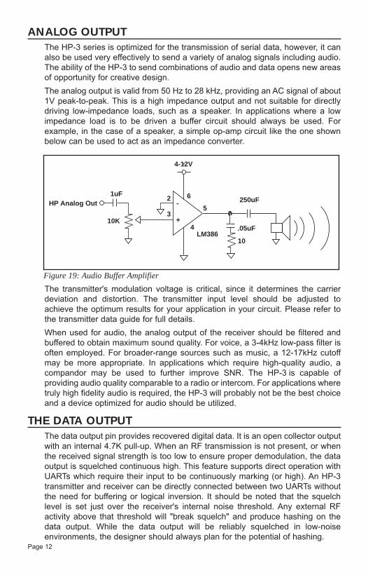
ANALOG OUTPUTThe HP-3 series is optimized for the transmission of serial data, however, it canalso be used very effectively to send a variety of analog signals including audio.The ability of the HP-3 to send combinations of audio and data opens new areasof opportunity for creative design.
The analog output is valid from 50 Hz to 28 kHz, providing an AC signal of about1V peak-to-peak. This is a high impedance output and not suitable for directlydriving low-impedance loads, such as a speaker. In applications where a lowimpedance load is to be driven a buffer circuit should always be used. Forexample, in the case of a speaker, a simple op-amp circuit like the one shownbelow can be used to act as an impedance converter.
The transmitter's modulation voltage is critical, since it determines the carrierdeviation and distortion. The transmitter input level should be adjusted toachieve the optimum results for your application in your circuit. Please refer tothe transmitter data guide for full details.
When used for audio, the analog output of the receiver should be filtered andbuffered to obtain maximum sound quality. For voice, a 3-4kHz low-pass filter isoften employed. For broader-range sources such as music, a 12-17kHz cutoffmay be more appropriate. In applications which require high-quality audio, acompandor may be used to further improve SNR. The HP-3 is capable ofproviding audio quality comparable to a radio or intercom. For applications wheretruly high fidelity audio is required, the HP-3 will probably not be the best choiceand a device optimized for audio should be utilized.
Page 12
HP Analog Out
10K
62
3+
-
4LM386
5
.05uF
1uF250uF
10
4-12V
Figure 19: Audio Buffer Amplifier
THE DATA OUTPUTThe data output pin provides recovered digital data. It is an open collector outputwith an internal 4.7K pull-up. When an RF transmission is not present, or whenthe received signal strength is too low to ensure proper demodulation, the dataoutput is squelched continuous high. This feature supports direct operation withUARTs which require their input to be continuously marking (or high). An HP-3transmitter and receiver can be directly connected between two UARTs withoutthe need for buffering or logical inversion. It should be noted that the squelchlevel is set just over the receiver's internal noise threshold. Any external RFactivity above that threshold will "break squelch" and produce hashing on thedata output. While the data output will be reliably squelched in low-noiseenvironments, the designer should always plan for the potential of hashing.

Figure 21: Typical Application - RS-232 Interface
AN
TE
NN
AG
ND
GN
DG
ND
GN
DG
ND
GN
DG
ND
N/C
CS
0C
S1
/ SS
CL
OC
KC
S2
/ SS
DA
TA
PO
WE
R D
OW
NR
SS
IG
ND
/MO
DE
VC
CA
NA
LO
G
DA
TA
OU
T
1 2 3 4 5 6 7 8 9 10 11 12 13 14 15 16 17 18
716
+
+
+
+
+ C14.7 uF
C44.7 uF
C24.7 uF
C34.7 uF
C5220 uF
ChannelSelect
RX1
3 PositionDIP Switch
10
1345
6
215
2
J1DB-9F
U2MAX 232
5
AN
TE
NN
AG
ND
GN
DG
ND
GN
DG
ND
GN
DG
ND
N/C
CS
OC
S1
/ SS
CL
OC
KC
S2
/ SS
DA
TA
PO
WE
R D
OW
NR
SS
IG
ND
/MO
DE
VC
CA
NA
LO
G
DA
TA
OU
T
1 2 3 4 5 6 7 8 9 10 11 12 13 14 15 16 17 18
1
2
3
4
5
6
7
8
9
D0
D1
D2
D3
VT
DIN
OSC1
OSC2
GND
VCC
A7
A6
A5
A4
A3
A2
A1
A0
18
17
16
15
14
13
12
11
10ChannelSelect
RX1
S13-PositionDIP Switch
Outputto User
U2HT694
S28-PositionDIP Switch
Address Select
390K
Page 13
Figure 20: Typical Application - Remote-Control Receiver
DATA CONSIDERATIONSOnce an RF link has been established, the challenge becomes how to effectivelytransfer information across it. For simple control or status signals such as buttonpresses or switch closures, consider using an encoder and decoder IC set.These chips are available from several manufacturers including Linx, Microchip,Holtek, and Motorola. These chips take care of all encoding, error checking, anddecoding functions. They generally provide a number of inputs to which switchescan be directly connected, and address or security bits to prevent unintentionalactivation. These IC's are an excellent way to avoid protocol development andbring basic remote control/status products quickly and inexpensively to market.
In most applications the modules will be interfaced to a microprocessor. A UARTmay be employed or an output pin of the microprocessor "bit-banged" to createa data stream. While many RF solutions impose complex formatting andbalancing requirements, the HP-3 series was designed to be as transparent aspossible. The HP-3 does not encode or packetize the data in any manner. Thistransparency gives the designer tremendous flexibility in the structure of aprotocol. Of course the performance and reliability of the link are dependent onthe quality of external software and hardware. To properly apply the receiver, itis critical to understand the differences between a wired and a wirelessenvironment. At each point in the system there are timing and data-corruptionissues that should be understood and accounted for. The following sectionprovides a brief overview of these issues.

Page 14
PROTOCOL CONSIDERATIONSAs previously indicated, the module's transparency allows for virtually unlimitedprotocol types and techniques. This section is meant only to illustrate generalissues a designer should address to ensure product reliability in the field. Yourapplication may call for or benefit from an entirely different protocol structure.
It is a good idea to structure the data being sent into small packets so that errorscan be managed without affecting large amounts of data. Packets should betransmitted without space between bytes. When using a UART the followingpacket format is often followed:
[ uart sync-byte ] [ start-byte ] [ data-packet ]
The UART sync-byte is used to ensure that the start-bit for the start-byte will becorrectly detected. It is a single byte with a value of 255 (0FF hex). A start-byteoften follows the sync-byte to intelligently qualify the data-packet which willfollow. Detection of the start-byte would be performed by the computer ormicrocontroller connected to the receiver.
TIMING CONSIDERATIONSThere are four major timing considerations the engineer must be aware of whendesigning with the HP-3 Series receiver. These are shown in the table below.
T1 is the maximum amount of time that can elapse without a data transition. Datamust always be considered in both the analog and the digital domain. Because thedata stream is asynchronous and no particular format is imposed, it is possible forthe data to meet the receiver's baud-rate requirement yet violate the analogfrequency parameters. For example, if a 255 (0FF hex) were sent continuously thereceiver would view the data as a DC level. The receiver would hold that level untila transition was required to meet the minimum frequency requirement. If notransition occurred, data integrity could not be guaranteed. Thus, while noparticular structure or balancing requirement is imposed, the designer must ensurethat both analog and digital signals meet the required transition specification.
T2 is the worst-case time needed for a powered-up module to switch betweenchannels after a valid channel selection. This time does not include externaloverhead for loading a desired channel in the serial channel-selection mode.
T3 is the time to receiver-readiness from the PDN pin going high. Receiver readinessis determined by valid data at the RXDATA pin. (This assumes an incoming datastream and the presence of stable supply on Vcc pin).
T4 is the time to receiver-readiness from the application of Vcc. Receiver readiness isdetermined by valid data at the RXDATA pin. (This assumes an incoming datastream and the PDN pin is high or open).
Parameter Description Max.
T1 Max time between 20mSecdata output transitions
T2 Max Channel-Change Time 1.5mSec(Time to Valid Data)
T3 Receiver Turn-on Time (Via PDN) 3mSec
T4 Receiver Turn-on Time (Via VCC) 7mSec
Page 15
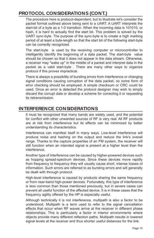
PROTOCOL CONSIDERATIONS (CONT.)The procedure here is protocol-dependent, but to illustrate let's consider thepacket format outlined above being sent to a UART. A UART interprets thestart-bit of a byte as a 1-0 transition. When the incoming data is 101010, orhash, it is hard to actually find the start bit. This problem is solved by theUART sync-byte. The purpose of the sync-byte is to create a high markingperiod of at least a byte-length so that the start bit of the following start-bytecan be correctly recognized.
The start-byte is used by the receiving computer or microcontroller tointelligently identify the beginning of a data packet. The start-byte valueshould be chosen so that it does not appear in the data stream. Otherwise,a receiver may "wake up" in the middle of a packet and interpret data in thepacket as a valid start-byte . There are many other ways to organizeprotocol if this proves impractical.
There is always a possibility of bursting errors from interference or changingsignal conditions causing corruption of the data packet, so some form oferror checking should be employed. A simple checksum or CRC could beused. Once an error is detected the protocol designer may wish to simplydiscard the corrupt data or develop a scheme for correcting it or requestingits retransmission.
INTERFERENCE CONSIDERATIONSIt must be recognized that many bands are widely used, and the potentialfor conflict with other unwanted sources of RF is very real. All RF productsare at risk from interference but its effects can be minimized by betterunderstanding its characteristics.
Interference can manifest itself in many ways. Low-level interference willproduce noise and hashing on the output and reduce the link's overallrange. Thanks to the capture properties of an FM system, the receiver willstill function when an intended signal is present at a higher level than theinterference.
Another type of interference can be caused by higher-powered devices suchas hopping spread-spectrum devices. Since these devices move rapidlyfrom frequency to frequency they will usually cause short, intense losses ofinformation. Such errors are referred to as bursting errors and will generallybe dealt with through protocol.
High-level interference is caused by products sharing the same frequencyor from near-band high-power devices. Fortunately, this type of interferenceis less common than those mentioned previously, but in severe cases canprevent all useful function of the affected device. It is in these cases that thefrequency agility offered by the HP is especially useful.
Although technically it is not interference, multipath is also a factor to beunderstood. Multipath is a term used to refer to the signal cancellationeffects that occur when RF waves arrive at the receiver in different phaserelationships. This is particularly a factor in interior environments whereobjects provide many different reflection paths. Multipath results in loweredsignal levels at the receiver and thus shorter useful distances for the link.
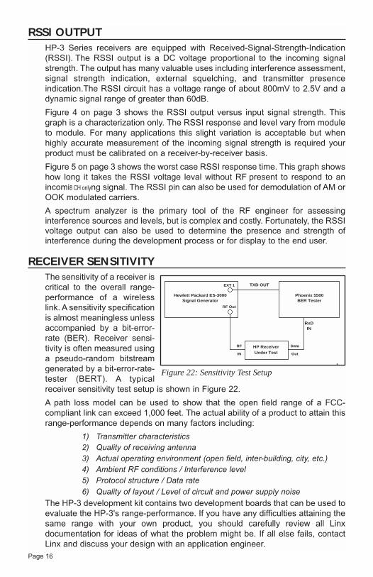
RSSI OUTPUTHP-3 Series receivers are equipped with Received-Signal-Strength-Indication(RSSI). The RSSI output is a DC voltage proportional to the incoming signalstrength. The output has many valuable uses including interference assessment,signal strength indication, external squelching, and transmitter presenceindication.The RSSI circuit has a voltage range of about 800mV to 2.5V and adynamic signal range of greater than 60dB.
Figure 4 on page 3 shows the RSSI output versus input signal strength. Thisgraph is a characterization only. The RSSI response and level vary from moduleto module. For many applications this slight variation is acceptable but whenhighly accurate measurement of the incoming signal strength is required yourproduct must be calibrated on a receiver-by-receiver basis.
Figure 5 on page 3 shows the worst case RSSI response time. This graph showshow long it takes the RSSI voltage leval without RF present to respond to anincomi8 CH onlyng signal. The RSSI pin can also be used for demodulation of AM orOOK modulated carriers.
A spectrum analyzer is the primary tool of the RF engineer for assessinginterference sources and levels, but is complex and costly. Fortunately, the RSSIvoltage output can also be used to determine the presence and strength ofinterference during the development process or for display to the end user.
Page 16
RECEIVER SENSITIVITYThe sensitivity of a receiver iscritical to the overall range-performance of a wirelesslink. A sensitivity specificationis almost meaningless unlessaccompanied by a bit-error-rate (BER). Receiver sensi-tivity is often measured usinga pseudo-random bitstreamgenerated by a bit-error-rate-tester (BERT). A typicalreceiver sensitivity test setup is shown in Figure 22.
A path loss model can be used to show that the open field range of a FCC-compliant link can exceed 1,000 feet. The actual ability of a product to attain thisrange-performance depends on many factors including:
1) Transmitter characteristics2) Quality of receiving antenna3) Actual operating environment (open field, inter-building, city, etc.)4) Ambient RF conditions / Interference level5) Protocol structure / Data rate
6) Quality of layout / Level of circuit and power supply noise
The HP-3 development kit contains two development boards that can be used toevaluate the HP-3's range-performance. If you have any difficulties attaining thesame range with your own product, you should carefully review all Linxdocumentation for ideas of what the problem might be. If all else fails, contactLinx and discuss your design with an application engineer.
Figure 22: Sensitivity Test Setup
RF
IN
RF Out
EXT 1
Data
Out
HP ReceiverUnder Test
Phoenix 5500BER Tester
Hewlett Packard ES-3000Signal Generator
RxDIN
TXD OUT

Page 17
GENERAL ANTENNA RULESThe following general rules should help in maximizing antenna performance:
1. Proximity to objects such as a user's hand or body, or metal objects willcause an antenna to detune. For this reason the antenna shaft and tipshould be positioned as far away from such objects as possible.
2. Optimum performance will be obtained from a 1/4- or 1/2-wave straight whipmounted at a right angle to the groundplane. In many cases, this isn'tdesirable for practical or ergonomic reasons; thus, an alternative antennastyle such as a helical, loop, patch, or base-loaded whip may be utilized andthe corresponding sacrifice in performance accepted.
3. If an internal antenna is used, keep it away from other metal components,particularly large items like transformers, batteries, and PCB tracks andgroundplanes. In many cases, the space around the antenna is as importantas the antenna itself.
4. In many antenna designs, particularly 1/4-wave whips,the groundplane acts as a counterpoise, forming, inessence, a 1/2-wave dipole. For this reason adequategroundplane area is essential. The groundplane canbe a metal case or ground-fill on the circuit board.Ideally, the groundplane to be used as counterpoiseshould have a surface area ≥ the overall length of the1/4-wave radiating element and be oriented at a 90°angle. Such an orientation is often not practical due tosize and configuration constraints. Inthese instances a designer mustmake the best use of the areaavailable to create as muchgroundplane in proximity to the baseof the antenna as possible. Ininstances where the antenna isremotely located or the antenna isnot in close proximity to a circuitboard plane or grounded metal case,a small metal plate may be fabricatedto maximize antenna performance.
5. Remove the antenna as far as possible from potential interference sourcessuch as switching power supplies, oscillators, motors and relays.Remember, the single best weapon against such problems is attention toplacement and layout. Filter the module's power supply with a high-frequency bypass capacitor. Place adequate groundplane under allpotential sources of noise. Shield noisy board areas whenever practical.
6. In some applications it is advantageous to place the receiver and itsantenna away from the main equipment. This avoids interference problemsand allows the antenna to be oriented for optimum RF performance. Alwaysuse 50Ω coax such as RG-174 for the remote feed.
I
E DIPOLEELEMENT
GROUNDPLANE
VIRTUAL λ/4DIPOLE
λ/4
λ/4
VERTICAL λ/4 GROUNDEDANTENNA (MARCONI)
OPTIMUM
USEABLENOT RECOMMENDED
NUTGROUNDPLANE
(MAY BE NEEDED)
CASE
Figure 23: Antenna Orientations

ANTENNA CONSIDERATIONSThe choice of antennas is one of themost critical and often overlookeddesign considerations. The range,performance, and legality of thereceiver is critically dependent on theantenna utilized. While adequateantenna performance can often beobtained by trial and error methods,professionally designed antennas,such as those offered by Linx, canprovide superior performance,repeatability and legal compliance.For complete details on the Linx antenna line, visit the Linx website atwww.linxtechnologies.com, or call (800)736-6677.The following sections look at some of the basic considerations involved in thedesign and selection of antennas. For a more comprehensive discussion pleaserefer to Linx applications note #00500 "Antennas: Design, Application,Performance".
Page 18
ANTENNA SHARINGIn cases where a transmitter and receivermodule are combined to form a transceiverit is often advantageous to share a singleantenna. To accomplish this an antennaswitch must be used to provide isolationbetween the modules. There is a widevariety of antenna switches availablewhich are cost-effective and straight-forward to use. Among the most popularare switches from Alpha and NEC. Lookfor an antenna switch that has highisolation and low loss at the desiredfrequency of operation. Generally, the TX or RX status of a switch will becontrolled by a product's microprocessor, but selection may also be mademanually by the user. In some cases where the characteristics of the TX and RXantennas need to be different or switch losses are unacceptable it may be moreappropriate to utilize two discrete antennas.
Antenna
TransmitterModule
ReceiverModule
0.1µF
0.1µF
0.1µF
0.1µF
0.1µF
GND
GND
VDD
Select
Figure 25: Typical Antenna Switch
CONNECTOR OPTIONSThe FCC requires that antennasdesigned for use on Part 15 productsbe either permanently attached, orutilize a unique and proprietaryconnector not available to thegeneral public. In cases where theantenna needs to be removable,Linx offers a full line of connectorsdesigned to comply with theserequirements.
Figure 23: Linx Antennas
Figure 24: Linx Connectors

Page 19
Specialty Styles
Whip Style
Loop Style
1/4-wave wire lengthfrequencies:
433MHz = 6.5"868MHz = 3.24"902-928MHz = 3.06"
COMMON ANTENNA STYLESThe antenna is a critical and often overlooked component which has a significanteffect on the overall range, performance and legality of an RF link. There arehundreds of antenna styles that can be successfully employed with the HP-3Series. Following is a brief discussion of the most commonly utilized styles.
A whip-style monopole antenna provides outstanding overallperformance and stability. A low-cost whip can be easilyfabricated from wire or rod, but most product designers opt forthe consistent performance and cosmetic appeal of aprofessionally made model. To meet this need, Linx offers awide variety of straight and reduced-height whip-style antennasin permanent and connectorized mounting styles.
The wavelength of the operational frequency determines anantenna's overall length. Since a full wavelength is often quitelong, a partial 1/4-wave antenna is normally employed. Its sizeand natural radiation resistance make it well-matched to Linxmodules. The approximate length for a straight 1/4-waveantenna can be easily found using the formula below. It is alsopossible to reduce the overall height of the antenna by using ahelical winding; therefore, the physical appearance is not alwaysan indicator of the antenna's frequency.
Linx offers a wide variety of specialized antenna styles andvariations. Many of these styles utilize helical elements toreduce the overall antenna size while maintaining reasonableperformance. A helical antenna's bandwidth is often quitenarrow and the antenna can detune in proximity to other objects,so care must be exercised in layout and placement.
A loop- or trace-style antenna is normally printed directly on aproduct's PCB. The element can be made self-resonant orexternally resonated with discrete components but its actuallayout is product specific. Despite its cost advantages, PCBantenna styles are generally inefficient and are very sensitive tochanges in layout or substrate. In addition, printed styles aredifficult to engineer, requiring the use of expensive equipmentincluding a network analyzer. An improperly designed loop willhave a high SWR at the desired frequency which can introduceinstability in the RF stages.
Linx offers low-cost planar and chip antennas which mountdirectly to a product's PCB. These tiny antennas do not requiretesting and provide excellent performance in light of theircompact size. They offer a preferable alternative to the oftenproblematic "printed" antenna.
L =234
F MHz234
= .255
.255 x 12" = 3.06"916MHz
Where:L=length in feet of quarter-wavelength F=operating frequency in megahertz
Example:

Page 20
LEGAL CONSIDERATIONS
When working with RF, a clear distinction must be made between what is technicallypossible and what is legally acceptable in the country where operation is intended.Many manufacturers have avoided incorporating RF into their products as a result ofuncertainty and even fear of the approval and certification process. Here at Linx ourdesire is not only to expedite the design process, but also to assist you in achievinga clear idea of what is involved in obtaining the necessary approvals to legally marketyour completed product.
In the United States the approval process is actually quite straightforward. Theregulations governing RF devices and the enforcement of them are the responsibilityof the Federal Communications Commission (FCC). The regulations are contained inthe Code of Federal Regulations (CFR), Title 47. Title 47 is made up of numerousvolumes; however, all regulations applicable to this module are contained in volume0-19. It is strongly recommended that a copy be obtained from the GovernmentPrinting Office in Washington, or from your local government book store. Excerpts ofapplicable sections are included with Linx evaluation kits or may be obtained from theLinx Technologies web site (www.linxtechnologies.com). In brief, these rules requirethat any device which intentionally radiates RF energy be approved, that is, tested,for compliance and issued a unique identification number. This is a relatively painlessprocess. Linx offers full EMC pre-compliance testing in our HP/Emco-equipped testcenter. Final compliance testing is then performed by one of the many independenttesting laboratories across the country. Many labs can also provide other certificationsthe product may require at the same time, such as UL, CLASS A/B, etc. Once yourcompleted product has passed, you will be issued an ID number which is then clearlyplaced on each product manufactured.
Questions regarding interpretations of the Part 2 and Part-15 rules or measurementprocedures used to test intentional radiators, such as the HP-3 modules, forcompliance with the Part-15 technical standards, should be addressed to:
Federal Communications Commission
Equipment Authorization Division
Customer Service Branch, MS 1300F2
7435 Oakland Mills Road
Columbia, MD 21046
Tel: (301) 725-1585 / Fax: (301) 344-2050 E-Mail: [email protected]
International approvals are slightly more complex, although many modules aredesigned to allow all international standards to be met. If you are considering theexport of your product abroad, you should contact Linx Technologies to determine thespecific suitability of the module to your application.
All Linx modules are designed with the approval process in mind and thus much ofthe frustration that is typically experienced with a discrete design is eliminated.Approval is still dependent on factors such as the choice of antennas, correct use ofthe frequency selected, and physical layout. While some extra cost and design effortare required to address these issues, the additional usefulness and profitability addedto a product by RF makes the effort more than worthwhile.
NOTE: HP-3 Series modules are intended to allow for full Part-15 compliance;however, they are not approved by the FCC or any other agency worldwide. Thisis because the module's performance and legality may be affected by externalfactors specific to a user's application. The purchaser understands that testingand approvals of a finished product may be required prior to the sale or operationof the device, and agrees to utilize the component in keeping with all lawsgoverning their use in the country of operation.

Page 21
SURVIVING AN RF IMPLEMENTATIONThe addition of wireless capabilities brings an excitingnew dimension to any product. It also means thatadditional effort and commitment will be needed to bringthe product successfully to market. By utilizing an RFmodule, such as the HP-3, the design and approvalprocess will be greatly simplified. It is still important,however, to have an objective view of the stepsnecessary to ensure a successful RF integration. Sincethe capabilities of each customer vary widely it is difficultto recommend one particular design path, but mostprojects follow steps similar to those shown at the right.
In reviewing this sample design path you may noticethat Linx offers a variety of services, such asantenna design, and FCC prequalification, that areunusual for a high-volume component manufacturer.These services, along with an exceptional level oftechnical support, are offered because we recognizethat RF is a complex science requiring the highestcaliber of products and support. "Wireless MadeSimple" is more than just a motto, it's ourcommitment. By choosing Linx as your RF partnerand taking advantage of the resources we offer, youwill not only survive implementing RF, but you mayeven find the process enjoyable.
DECISION TO UTILIZE RF IS MADE
RESEARCH RF OPTIONS
LINX MODULE IS CHOSEN
ORDER EVALUATION KIT(S)
TEST MODULE(S) WITHBASIC HOOKUP
INTERFACE TO CHOSEN CIRCUIT AND DEBUG
CONSULT LINX REGARDINGANTENNA OPTIONS AND DESIGN
LAY OUT BOARD
SEND PRODUCTION-READYPROTOTYPE TO LINX
FOR EMC PRESCREENING
OPTIMIZE USING RF SUMMARY GENERATED BY LINX
SEND TO PART 15TEST FACILITY
RECEIVE FCC ID #
COMMENCE SELLING PRODUCT
TYPICAL STEPS FORIMPLEMENTING RF
HELPFUL APPLICATION NOTES FROM LINXIt is not the intention of this manual to address in depth many of the issues thatshould be considered to ensure that the modules function correctly and deliverthe maximum possible performance. As you proceed with your design you maywish to obtain one or more of the following application notes, which address indepth key areas of RF design and application of Linx products. Theseapplications notes are available on-line at www.linxtechnologies.com or bycontacting the Linx literature department.
00100 RF 101: Information for the RF challenged
00126 Considerations for operation in the 902MHz to 928MHz band
00130 Modulation techniques for low-cost RF data links
00140 The FCC Road: Part 15 from concept to approval
00150 Use and design of T-attenuation pads
00155 Serial loading techniques for the HP-3 Series (PS Versions)
00161 Considerations for sending data with the HP-3 Series
00500 Antennas: Design, Application, Performance
NOTE # LINX APPLICATION NOTE TITLE

Page 22
*This channel is not counted as it is the Serial Mode default channel (see page 11)
SERIAL CHANNEL SELECTION TABLECHANNEL TX FREQUENCY RX LO CHANNEL TX FREQUENCY RX LO
0 902.62 867.92 51 915.37 880.671 902.87 868.17 52 915.62 880.922 903.12 868.42 53 915.87 881.173 903.37 868.67 54 916.12 881.424 903.62 868.92 55 916.37 881.675 903.87 869.17 56 916.62 881.926 904.12 869.42 57 916.87 882.177 904.37 869.67 58 917.12 882.428 904.62 869.92 59 917.37 882.679 904.87 870.17 60 917.62 882.9210 905.12 870.42 61 917.87 883.1711 905.37 870.67 62 918.12 883.4212 905.62 870.92 63 918.37 883.6713 905.87 871.17 64 918.62 883.9214 906.12 871.42 65 918.87 884.1715 906.37 871.67 66 919.12 884.4216 906.62 871.92 67 919.37 884.6717 906.87 872.17 68 919.62 884.9218 907.12 872.42 69 919.87 885.1719 907.37 872.67 70 920.12 885.4220 907.62 872.92 71 920.37 885.6721 907.87 873.17 72 920.62 885.9222 908.12 873.42 73 920.87 886.1723 908.37 873.67 74 921.12 886.4224 908.62 873.92 75 921.37 886.6725 908.87 874.17 76 921.62 886.9226 909.12 874.42 77 921.87 887.1727 909.37 874.67 78 922.12 887.4228 909.62 874.92 79 922.37 887.6729 909.87 875.17 80 922.62 887.9230 910.12 875.42 81 922.87 888.1731 910.37 875.67 82 923.12 888.4232 910.62 875.92 83 923.37 888.6733 910.87 876.17 84 923.62 888.9234 911.12 876.42 85 923.87 889.1735 911.37 876.67 86 924.12 889.4236 911.62 876.92 87 924.37 889.6737 911.87 877.17 88 924.62 889.9238 912.12 877.42 89 924.87 890.1739 912.37 877.67 90 925.12 890.4240 912.62 877.92 91 925.37 890.6741 912.87 878.17 92 925.62 890.9242 913.12 878.42 93 925.87 891.1743 913.37 878.67 94 926.12 891.4244 913.62 878.92 95 926.37 891.6745 913.87 879.17 96 926.62 891.9246 914.12 879.42 97 926.87 892.1747 914.37 879.67 98 927.12 892.4248 914.62 879.92 99 927.37 892.6749 914.87 880.17 100 927.62 892.9250* 915.12 880.42 = Also available in Parallel Mode

Page 23
VSWR Insertion Power PowerLoss Transmitted Reflected(dB) (%) (%)
17.391 -6.87 20.57% 79.43%11.610 -5.35 29.21% 70.79%8.724 -4.33 36.90% 63.10%6.997 -3.59 43.77% 56.23%5.848 -3.02 49.88% 50.12%5.030 -2.57 55.33% 44.67%4.419 -2.20 60.19% 39.81%3.946 -1.90 64.52% 35.48%3.570 -1.65 68.38% 31.62%3.010 -1.26 74.88% 25.12%2.615 -0.97 80.05% 19.95%2.323 -0.75 84.15% 15.85%2.100 -0.58 87.41% 12.59%1.925 -0.46 90.00% 10.00%1.433 -0.14 96.84% 3.16%1.222 -0.04 99.00% 1.00%1.119 -0.01 99.68% 0.32%1.065 0.00 99.90% 0.10%1.034 0.00 99.97% 0.03%1.020 0.00 99.99% 0.01%
MISMATCH CONVERSION TABLE
NOTES:

Page 24
LINX TECHNOLOGIES, INC.575 S.E. ASHLEY PLACEGRANTS PASS, OR 97526
Phone: (541) 471-6256FAX: (541) 471-6251www.linxtechnologies.com
U.S. CORPORATE HEADQUARTERS:
Linx Technologies is continually striving to improve the quality and function of its products; forthis reason, we reserve the right to make changes without notice. The information contained inthis Data Sheet is believed to be accurate as of the time of publication. Specifications are basedon representative lot samples. Values may vary from lot to lot and are not guaranteed. LinxTechnologies makes no guarantee, warranty, or representation regarding the suitability of anyproduct for use in a specific application. None of these devices is intended for use inapplications of a critical nature where the safety of life or property is at risk. The user assumesfull liability for the use of product in such applications. Under no conditions will LinxTechnologies be responsible for losses arising from the use or failure of the device in anyapplication, other than the repair, replacement, or refund limited to the original product purchaseprice. Some devices described in this publication are patented. Under no circumstances shallany user be conveyed any license or right to the use or ownership of these patents.
Disclaimer
© 2003 by Linx Technologies, Inc. The stylizedLinx logo, Linx, and "Wireless made Simple"are the trademarks of Linx Technologies, Inc. Printed in U.S.A.