Embed Size (px)
Citation preview


HP LaserJet M3027/M3035 Multifunction
Service Manual

Copyright and License
© 2006 Copyright Hewlett-PackardDevelopment Company, L.P.
Reproduction, adaptation, or translationwithout prior written permission is prohibited,except as allowed under the copyright laws.
The information contained herein is subjectto change without notice.
The only warranties for HP products andservices are set forth in the express warrantystatements accompanying such productsand services. Nothing herein should beconstrued as constituting an additionalwarranty. HP shall not be liable for technicalor editorial errors or omissions containedherein.
Part number: CB414-90940
Edition 1, 10/2006
Trademark Credits
Adobe®, Acrobat®, and PostScript® aretrademarks of Adobe Systems Incorporated.
Intel® and Pentium® are trademarks orregistered trademarks of Intel Corporation orits subsidiaries in the United States and othercountries.
Linux is a U.S. registered trademark of LinusTorvalds.
Microsoft®, Windows®, and Windows NT®
are U.S. registered trademarks of MicrosoftCorporation.
UNIX® is a registered trademark of The OpenGroup.
ENERGY STAR® and the ENERGY STARlogo® are U.S. registered marks of the UnitedStates Environmental Protection Agency.

Table of contents
1 Product InformationChapter contents .................................................................................................................................. 1Device configurations ........................................................................................................................... 2Features ............................................................................................................................................... 3Walkaround .......................................................................................................................................... 5
Device parts ......................................................................................................................... 5Interface ports ...................................................................................................................... 6
Device software .................................................................................................................................... 7Supported operating systems .............................................................................................. 7Minimum system requirements ............................................................................................ 7Supported printer drivers ..................................................................................................... 8Select the correct printer driver ............................................................................................ 9
Universal printer drivers ...................................................................................... 9Driver Autoconfiguration ...................................................................................... 9Update Now ........................................................................................................ 9HP Driver Preconfiguration ................................................................................. 9
Priority for print settings ..................................................................................................... 10Open the printer drivers ..................................................................................................... 11Software for Macintosh computers .................................................................................... 12
Remove software from Macintosh operating systems ...................................... 12Utilities ............................................................................................................................... 13
HP Web Jetadmin ............................................................................................. 13Embedded Web server ..................................................................................... 13HP Easy Printer Care software ......................................................................... 14
Supported operating systems ........................................................... 14Supported browsers ......................................................................... 14
Other components and utilities .......................................................................... 14Media specifications ........................................................................................................................... 15
General guidelines for media ............................................................................................. 15Paper to avoid ................................................................................................... 16Paper that can damage the device ................................................................... 16General media specifications ............................................................................ 17
Select print media .............................................................................................................. 17Supported media sizes ...................................................................................... 18Supported media types ..................................................................................... 19
2 Installation and configurationChapter contents ................................................................................................................................ 21Site preparation .................................................................................................................................. 22
ENWW iii

Location specifications ....................................................................................................... 22Operating environment ..................................................................................................... 22
Install trays ......................................................................................................................................... 23Load tray 1 (multipurpose tray) .......................................................................................... 23Load tray 2 and optional tray 3 ......................................................................................... 25Configure trays .................................................................................................................. 26
Install supplies .................................................................................................................................... 27Supply replacement guidelines .......................................................................................... 27Change the print cartridge ................................................................................................. 27
Install accessories .............................................................................................................................. 30Install memory ................................................................................................................... 30
Install device memory ....................................................................................... 30Check DIMM installation .................................................................................................... 34Enable memory for Windows ............................................................................................. 34Use HP Jetdirect print server cards ................................................................................... 35
Install an HP Jetdirect print server card ............................................................ 35Remove an HP Jetdirect print server card ........................................................ 36
3 MaintenanceChapter contents ................................................................................................................................ 37Manage supplies ................................................................................................................................ 38
Supplies life ....................................................................................................................... 38Approximate print-cartridge replacement intervals ............................................................ 38Manage the print cartridge ................................................................................................. 39
Print-cartridge storage ....................................................................................... 39Use genuine HP print cartridges ....................................................................... 39HP policy on non-HP print cartridges ................................................................ 39Print-cartridge authentication ............................................................................ 39HP fraud hotline and Web site .......................................................................... 39
Clean the device ................................................................................................................................. 40Clean the exterior .............................................................................................................. 40Clean the ADF ................................................................................................................... 40Clean the scanner lid backing ............................................................................................ 42Clean the scanner glass .................................................................................................... 43Clean the fuser .................................................................................................................. 44Clean spilled toner ............................................................................................................. 44
Management tools .............................................................................................................................. 45Use information pages ....................................................................................................... 45Use the HP Easy Printer Care software ............................................................................ 47
Open the HP Easy Printer Care software ......................................................... 47HP Easy Printer Care software sections ........................................................... 48
Use the embedded Web server ......................................................................................... 49Open the embedded Web server by using a network connection ..................... 49Embedded Web server sections ....................................................................... 50
Use HP Web Jetadmin software ........................................................................................ 52Use the HP Printer Utility for Macintosh ............................................................................ 52
Open the HP Printer Utility ................................................................................ 52HP Printer Utility features .................................................................................. 53
4 Theory of operation
iv ENWW

Chapter contents ................................................................................................................................ 55Basic operation ................................................................................................................................... 56
ADF/scanner system ......................................................................................................... 57ADF ................................................................................................................... 57
Sensors in the ADF .......................................................................... 57ADF paper path ................................................................................ 57
Scanner ............................................................................................................. 58Formatter ........................................................................................................................... 59Engine control unit (ECU) .................................................................................................. 60Pickup/feed/delivery system .............................................................................................. 62Laser/scanner system ........................................................................................................ 63Image-formation system .................................................................................................... 64
Step 1: Primary charging ................................................................................... 65Step 2: Laser beam exposure ........................................................................... 65Step 3: Developing ............................................................................................ 65Step 4: Transfer ................................................................................................ 66Step 5: Separation ............................................................................................ 66Step 6: Fusing ................................................................................................... 67Step 7: Drum cleaning ....................................................................................... 67
Internal components ........................................................................................................................... 68Timing ................................................................................................................................................. 69Print cartridge memory system ........................................................................................................... 73
5 Removal and replacementChapter contents ................................................................................................................................ 75Introduction ......................................................................................................................................... 77
Removal and replacement strategy .................................................................................. 77Electrostatic discharge ....................................................................................................... 77User-replaceable parts ...................................................................................................... 77Required tools .................................................................................................................... 78Before performing service .................................................................................................. 78Parts removal order ........................................................................................................... 79
Automatic document feeder (ADF) and scanner assemblies ............................................................. 80ADF assembly ................................................................................................................... 80
ADF cover ......................................................................................................... 80ADF input tray ................................................................................................... 82Control panel ..................................................................................................... 84ADF ................................................................................................................... 87
Scanner assembly ............................................................................................................. 90Covers ................................................................................................................................................ 94
Right-side cover ................................................................................................................. 94Formatter shield ................................................................................................................. 95Fax cover ........................................................................................................................... 96Left-side cover ................................................................................................................... 97Legal cover (dust cover) .................................................................................................. 100Back cover ....................................................................................................................... 101I/O cover .......................................................................................................................... 103Fax rail ............................................................................................................................. 104Top cover ......................................................................................................................... 105Front, right cover .............................................................................................................. 109
ENWW v

Fax accessory .................................................................................................................................. 111Disk drive .......................................................................................................................................... 113Formatter .......................................................................................................................................... 116Stapler .............................................................................................................................................. 117Stapler power-supply ........................................................................................................................ 123Right-side fan ................................................................................................................................... 128Engine control unit (ECU) ................................................................................................................. 131Left-side riser .................................................................................................................................... 138Fuser ................................................................................................................................................ 139Laser/scanner ................................................................................................................................... 142Access plate ..................................................................................................................................... 144Oblique-roller assembly .................................................................................................................... 146Left-side fan ...................................................................................................................................... 148High-voltage power supply (HVPS) .................................................................................................. 149Feed-guide assembly ....................................................................................................................... 156Main motor ....................................................................................................................................... 159Gear assembly ................................................................................................................................. 162Reinstallation notes for the gear assembly ...................................................................................... 165Tray 1 solenoid ................................................................................................................................. 166Tray 2 solenoid ................................................................................................................................. 167Pickup assembly .............................................................................................................................. 168Tray 1 media-present sensor and top-of-page sensor ..................................................................... 173E-label reader (memory tag) ............................................................................................................ 175Face-down-roller shaft ...................................................................................................................... 177Cartridge door .................................................................................................................................. 179Transfer roller ................................................................................................................................... 182Registration assembly ...................................................................................................................... 183Tray 1 pickup roller ........................................................................................................................... 186Tray 2 pickup roller ........................................................................................................................... 187Separation pad ................................................................................................................................. 189
6 TroubleshootingChapter contents .............................................................................................................................. 191Troubleshooting process .................................................................................................................. 192
Troubleshooting tree ........................................................................................................ 192Troubleshooting flowchart ................................................................................................ 193
1. Does the control-panel display show READY? ........................................... 1932. Can you print a configuration page? .......................................................... 1943. Does the device copy? ................................................................................ 1954. Does the device send a fax? ....................................................................... 1965. Does the device receive a fax? ................................................................... 1976. Can you print from a program? ................................................................... 1987. Does the job print as expected? .................................................................. 1998. Does the device select the correct trays? ................................................... 200
Control-panel messages .................................................................................................................. 201Control-panel message types .......................................................................................... 201Resolve control-panel messages ..................................................................................... 201
Clear jams ........................................................................................................................................ 214Common causes of jams ................................................................................................. 214Jam locations ................................................................................................................... 215
vi ENWW

Jam detection .................................................................................................................. 216Clear jams from the ADF ................................................................................................. 217Clear jams from the print-cartridge area .......................................................................... 219Clear jams from the input-tray areas ............................................................................... 220Clear jams from the duplexer ........................................................................................... 222Clear jams from the output-bin areas .............................................................................. 223
Interface troubleshooting ................................................................................................................. 225Communications checks .................................................................................................. 225LAN hardware test ........................................................................................................... 225
Service mode functions .................................................................................................................... 226Boot-up key sequences ................................................................................................... 226
Low-level boot-up key sequence for selecting a language, performing a coldreset, and enabling and disabling embedded LAN ......................................... 227Medium-level boot-up key sequence for initializing disks ............................... 227High-level boot-up key sequence for NVRAM initialization, manufacturing,and skipping disk-load and calibration ............................................................ 227
Service menu ................................................................................................................... 228Service ID ........................................................................................................................ 228
Restore the service ID ..................................................................................... 229Convert the service ID to an actual date ......................................................... 229
Troubleshooting tools ....................................................................................................................... 230Control-panel menus ....................................................................................................... 230
Print Quality menu ........................................................................................... 230Troubleshooting menu .................................................................................... 231
Early-boot diagnostic test ................................................................................................ 233Test pages ....................................................................................................................... 234
Engine-test page ............................................................................................. 234Formatter test page ......................................................................................... 235
Embedded Web server ................................................................................................... 235Gaining access to the embedded Web server ................................................ 235
Information tab ................................................................................ 235Settings tab ..................................................................................... 236Networking tab ............................................................................... 236Other links ...................................................................................... 236
Image defect ruler ............................................................................................................ 238Firmware updates and recovery ....................................................................................................... 239
Determine the current level of firmware ........................................................................... 239Download the new firmware from the HP Web site ......................................................... 239Transfer the new firmware to the device .......................................................................... 240
Use FTP to upgrade the firmware on a network connection ........................... 240Use HP Web Jetadmin to upgrade the firmware ............................................. 241Use MS-DOS commands to upgrade the firmware ......................................... 242
Upgrade the HP Jetdirect firmware .................................................................................. 242Troubleshoot general printing problems ........................................................................................... 243Troubleshoot media-handling problems ........................................................................................... 246
Multiple pages feed .......................................................................................................... 246Pages are wrinkled or folded ........................................................................................... 246Pages are skewed ........................................................................................................... 247
Troubleshoot print-quality problems ................................................................................................ 248Print-quality checklist ....................................................................................................... 248
ENWW vii

Image-defect examples ................................................................................................... 249Light print (partial page) .................................................................................................. 250Light print (entire page) ................................................................................................... 251Specks ............................................................................................................................. 251Dropouts .......................................................................................................................... 252Lines ................................................................................................................................ 252Gray background ............................................................................................................ 253Toner smear ................................................................................................................... 253Loose toner ..................................................................................................................... 254Repeating defects ........................................................................................................... 254Repeating image ............................................................................................................. 255Misformed characters ...................................................................................................... 255Page skew ....................................................................................................................... 256Curl or wave .................................................................................................................... 256Wrinkles or creases ......................................................................................................... 257Vertical white lines ........................................................................................................... 257Tire tracks ....................................................................................................................... 258White spots on black ....................................................................................................... 258Scattered lines ................................................................................................................ 259Blurred print .................................................................................................................... 259Random image repetition ................................................................................................. 260
Diagrams .......................................................................................................................................... 261Device component locations ............................................................................................ 261
Main assemblies ............................................................................................. 261Main parts ....................................................................................................... 262Sensors and switches ..................................................................................... 263Motors, fans, and solenoids ............................................................................ 264PCAs ............................................................................................................... 265
Wiring diagrams ............................................................................................................... 266
7 Parts and diagramsChapter contents .............................................................................................................................. 269Ordering parts and supplies ............................................................................................................. 270
Parts ................................................................................................................................ 270Related documentation and software .............................................................................. 270Supplies ........................................................................................................................... 270
Consumables and accessories ........................................................................................................ 271Consumables and accessories ........................................................................................ 271
ADF/scanner assembly .................................................................................................................... 272Covers .............................................................................................................................................. 274Internal components ......................................................................................................................... 276Tray 2 pickup assembly .................................................................................................................... 290Alphabetical parts list ....................................................................................................................... 292Numerical parts list ........................................................................................................................... 302
Appendix A Supplies and accessoriesOrder parts, accessories, and supplies ............................................................................................ 314
Order directly from HP ..................................................................................................... 314Order through service or support providers ..................................................................... 314
viii ENWW

Order directly through the embedded Web server (for printers that are connected to anetwork) ........................................................................................................................... 314Order directly through the HP Easy Printer Care software .............................................. 314
Part numbers .................................................................................................................................... 315Paper-handling accessories ............................................................................................ 315Print cartridge .................................................................................................................. 315Memory ............................................................................................................................ 315Cables and interfaces ...................................................................................................... 315Stapler accessories ......................................................................................................... 316Print media ....................................................................................................................... 316
Appendix B Service and supportHewlett-Packard limited warranty statement .................................................................................... 319Customer self repair warranty service .............................................................................................. 320Print cartridge limited warranty statement ........................................................................................ 320HP Customer Care ........................................................................................................................... 322
Online Services ................................................................................................................ 322Telephone support ........................................................................................................... 322Software utilities, drivers, and electronic information ....................................................... 322HP direct ordering for accessories or supplies ................................................................ 322HP service information ..................................................................................................... 322HP service agreements ................................................................................................... 322HP Easy Printer Care software ........................................................................................ 323HP support and information for Macintosh computers ..................................................... 323
HP maintenance agreements ........................................................................................................... 324On-site service agreements ............................................................................................. 324
Next-day on-site service .................................................................................. 324Weekly (volume) on-site service ..................................................................... 324
Repacking the device ...................................................................................................... 324Extended warranty ........................................................................................................... 325
Appendix C SpecificationsPhysical specifications ..................................................................................................................... 328Electrical specifications .................................................................................................................... 328Acoustic emissions ........................................................................................................................... 329Operating environment ..................................................................................................................... 329
Appendix D Regulatory informationFCC regulations ............................................................................................................................... 332Environmental product stewardship program ................................................................................... 333
Protecting the environment .............................................................................................. 333Ozone production ............................................................................................................ 333Power consumption ......................................................................................................... 333Toner consumption .......................................................................................................... 333Paper use ........................................................................................................................ 333Plastics ............................................................................................................................ 333HP LaserJet print supplies ............................................................................................... 333HP print supplies returns and recycling program information .......................................... 334Paper ............................................................................................................................... 334
ENWW ix

Material restrictions .......................................................................................................... 334Disposal of waste equipment by users in private households in the European Union .... 335Material Safety Data Sheet (MSDS) ................................................................................ 335For more information ....................................................................................................... 335
Telecom statement ........................................................................................................................... 337Declaration of conformity .................................................................................................................. 338Safety statements ............................................................................................................................. 339
Laser safety ..................................................................................................................... 339Canadian DOC regulations .............................................................................................. 339VCCI statement (Japan) .................................................................................................. 339Power cord statement (Japan) ......................................................................................... 339EMI statement (Korea) ..................................................................................................... 339EMI statement (Taiwan) ................................................................................................... 340Laser statement for Finland ............................................................................................. 340
Appendix E Working with memory and print server cardsOverview .......................................................................................................................................... 342
Glossary ........................................................................................................................................................... 343
Index ................................................................................................................................................................. 345
x ENWW

1 Product Information
Chapter contents● Device configurations
● Features
● Walkaround
● Device software
● Media specifications
ENWW Chapter contents 1

Device configurationsHP LaserJet M3027 HP LaserJet M3027x HP LaserJet M3035 HP LaserJet M3035xs
● Prints up to 27 pages-per-minute (ppm) on letter-sizedmedia, and up to 25 ppm onA4–sized media
● 256 megabytes (MB) total ofrandom access memory(RAM), upgradable up to512 MB
● Internal 40 gigabyte (GB) orlarger hard disk
● 100-sheet multipurpose tray(tray 1), 500-sheet input tray(tray 2), 50-sheet automaticdocument feeder (ADF),and 250-sheet output bin
● Hi-Speed universal serialbus (USB) 2.0 port andenhanced input/output(EIO) slot
● HP Jetdirect embeddedprint server for Ethernet10/100Base-T network
● One open dual inlinememory module (DIMM)slot
HP LaserJet M3027, plus:
● Automatic two-sidedprinting accessory
● 33.6 kpbs analog fax
● Prints up to 35 ppm onletter-sized media, and up to33 ppm on A4–sized media
● 256 MB total RAM,upgradable up to 512 MB
● Internal 40 GB or larger harddisk
● 100-sheet tray 1, 500-sheettray 2, 50-sheet ADF, and250-sheet output bin
● Hi-Speed USB 2.0 port andEIO slot
● HP Jetdirect embeddedprint server for Ethernet10/100Base-T network
● One open DIMM slot
● Automatic two-sidedprinting accessory
HP LaserJet M3035, plus:
● 33.6 kpbs analog fax
● 20-sheet conveniencestapler
● 500-sheet input tray(tray 3)
2 Chapter 1 Product Information ENWW

FeaturesFeature Description
Performance ● 400 MHz processor
User interface ● Control-panel help
● Windows® and Macintosh printer drivers
● Embedded Web server to gain access to support and to order supplies (administrator tool for network-connectedmodels only)
● HP Easy Printer Care software (a Web-based status and troubleshooting tool)
Printer drivers ● HP PCL 5
● HP PCL 6
● HP postscript level 3 emulation
Resolution ● FastRes 1200—produces 1200-dots-per-inch (dpi) print quality for fast, high-quality printing of business text andgraphics
● ProRes 1200—produces 1200-dpi printing for the best quality in line art and graphic images
Storage features ● Internal 40 GB or larger hard drive
● Fonts, forms, and other macros
● Job retention
Fonts ● 93 internal fonts available for PCL
● 80 printer-matching screen fonts in TrueType format available with the software solution
● Additional fonts can be added.
Accessories ● Optional 500-sheet input tray (tray 3) (standard on the HP LaserJet M3035xs MFP)
● 100-pin 133 MHz dual inline memory modules (DIMMs)
Connectivity ● Hi-Speed USB 2.0 connection
● HP Jetdirect full-featured embedded print server
● HP Web Jetadmin software
● Enhanced input/output (EIO) slot
● Foreign interface harness (FIH) port for attaching optional third-party paper-handling devices
Environmentalfeatures
● Sleep mode setting
● ENERGY STAR® qualified
Supplies ● The supplies status page contains information about toner level, page count, and estimated pages remaining.
● The product checks for an authentic HP print cartridge at cartridge installation.
● Internet-enabled supply-ordering capabilities (using HP Easy Printer Care software)
Accessibility ● The online user guide is compatible with text screen-readers.
● The print cartridge can be installed and removed by using one hand.
ENWW Features 3

Feature Description
● All doors and covers can be opened by using one hand.
● Media can be loaded in tray 1 by using one hand.
4 Chapter 1 Product Information ENWW

WalkaroundDevice parts
Before using the product, familiarize yourself with its components.
12
11
10
13
14
2
1
3
4
56
7
8
9
1 Optional tray 3
2 Tray 2
3 Tray 1 (pull to open)
4 Latch to open the front door (provides access to the print cartridge)
5 Top output bin
6 Control panel
7 Convenience stapler
8 Right-side cover (provides access to DIMMs)
9 On/off switch
10 Interface ports (see Interface ports on page 6)
11 Scanner assembly
12 ADF output bin
13 Automatic document feeder (ADF)
14 Rear output bin (pull to open)
ENWW Walkaround 5

Interface ports
1
23
4
5
7
6
1 Fax port (HP LaserJet M3027x and HP LaserJet M3035xs only)
2 Network connection
3 Foreign interface harness (FIH) port
4 Type A Hi-Speed USB 2.0 connection for adding accessories
5 Power connection
6 Type B Hi-Speed USB 2.0 connection for printing
7 EIO slot
6 Chapter 1 Product Information ENWW

Device softwareThe printing-system software is included with the device. See the getting started guide for installationinstructions.
The printing system includes software for end users and network administrators, and printer drivers foraccess to the device features and communication with the computer.
NOTE For a list of printer drivers and updated HP printer software, go to www.hp.com/go/LJM3027mfp_software or www.hp.com/go/LJM3035mfp_software.
Supported operating systemsThe device supports the following operating systems:
Full software installation
● Windows XP (32-bit and 64-bit)
● Windows Server 2003 (32-bit and 64-bit)
● Windows 2000
● Mac OS X V10.2.8, V10.3, V10.4 and later
Printer driver only
● Linux (Web only)
● UNIX model scripts (Web only)
NOTE For Mac OS V10.4 and later, PPC and Intel Core Processor Macs are supported.
Minimum system requirementsIn order to install and use the device software, your computer must meet the following minimumrequirements:
Windows requirements
● Pentium II (233 MHz) processor
● 64 MB of RAM
● 35 MB of disk space
● SVGA 800x600 16-bit color monitor
Macintosh requirements
● G3, G4, or G5 PowerPC processor
● 128 MB of RAM
● 30 to 50 MB of disk space
ENWW Device software 7

Supported printer drivers
Operating system1 PCL 5 PCL 6 PS level 3 emulation
Windows2,3
Mac OS X V10.2 and later
Linux4
1 Not all device features are available from all drivers or operating systems.2 For Windows 2000 and Windows XP (32-bit and 64-bit), download the PCL 5 driver from www.hp.com/go/
LJM3027mfp_software or www.hp.com/go/LJM3035mfp_software.3 For Windows XP (64-bit), download the PCL 6 driver from www.hp.com/go/LJM3027mfp_software or www.hp.com/go/
LJM3035mfp_software.4 For Linux, download the postscript level 3 emulation driver from www.hp.com/go/linuxprinting.
The printer drivers include online Help that has instructions for common printing tasks and also describesthe buttons, checkboxes, and drop-down lists that are in the printer driver.
8 Chapter 1 Product Information ENWW

Select the correct printer driverPrinter drivers allow you to gain access to the device features and allow the computer to communicatewith the device (using a printer language). Check the installation notes and readme files on the deviceCD for additional software and languages.
The device uses the PCL 5, PCL 6, and HP postscript level 3 emulation printer description language(PDL) drivers.
● Use the PCL 6 printer driver for the best overall performance.
● Use the PCL 5 printer driver for general office printing.
● Use the HP postscript level 3 emulation driver for printing from postscript level 3 emulation needs,or for postscript flash font support.
Universal printer driversThe HP Universal Print Driver Series for Windows includes separate HP postscript level 3 emulationand HP PCL 5 versions of a single driver that provides access to almost any HP device while providingsystem administrator with tools to manage devices more effectively. The Universal Print Driver isincluded on the device CD, under the Optional Software section. For more information, go towww.hp.com/go/universalprintdriver.
Driver AutoconfigurationThe HP LaserJet PCL 5, PCL 6, and PS level 3 emulation drivers for Windows 2000 and Windows XPfeature automatic discovery and driver configuration for device accessories at the time of installation.Some accessories that the Driver Autoconfiguration supports are the duplexing unit, optional papertrays, and dual inline memory modules (DIMMs).
Update NowIf you have modified the device configuration since installation, the driver can be automatically updatedwith the new configuration. In the Properties dialog box (see Open the printer drivers on page 11),on the Device Settings tab, click the Update Now button to update the driver.
HP Driver PreconfigurationHP Driver Preconfiguration is a software architecture and set of tools that you can use to customize anddistribute HP software in managed corporate printing environments. Using HP Driver Preconfiguration,information technology (IT) administrators can preconfigure the printing and default settings forHP printer drivers before installing the drivers in the network environment. For more information, seethe HP Driver Preconfiguration Support Guide, which is available at www.hp.com/go/hpdpc_sw.
ENWW Device software 9

Priority for print settingsChanges to print settings are prioritized depending on where the changes are made:
NOTE The names of commands and dialog boxes might vary depending on your softwareprogram.
● Page Setup dialog box: Click Page Setup or a similar command on the File menu of the programyou are working in to open this dialog box. Settings changed here override settings changedanywhere else.
● Print dialog box: Click Print, Print Setup, or a similar command on the File menu of the programyou are working in to open this dialog box. Settings changed in the Print dialog box have a lowerpriority and do not override changes made in the Page Setup dialog box.
● Printer Properties dialog box (printer driver): Click Properties in the Print dialog box to openthe printer driver. Settings changed in the Printer Properties dialog box do not override settingsanywhere else in the printing software.
● Default printer driver settings: The default printer driver settings determine the settings used inall print jobs, unless settings are changed in the Page Setup, Print, or Printer Properties dialogboxes.
● Printer control panel settings: Settings changed at the printer control panel have a lower prioritythan changes made anywhere else.
10 Chapter 1 Product Information ENWW

Open the printer drivers
Operating System To change the settings for allprint jobs until the softwareprogram is closed
To change the default settingsfor all print jobs
To change the deviceconfiguration settings
Windows 2000, XP,and Server 2003
1. On the File menu in thesoftware program, clickPrint.
2. Select the driver, and thenclick Properties orPreferences.
The steps can vary; thisprocedure is most common.
1. Click Start, click Settings,and then click Printers orPrinters and Faxes.
2. Right-click the driver icon,and then select PrintingPreferences.
1. Click Start, click Settings,and then click Printers orPrinters and Faxes.
2. Right-click the driver icon,and then selectProperties.
3. Click the Device Settingstab.
Mac OS X V10.2.8,V10.3, V10.4 andlater
1. On the File menu, clickPrint.
2. Change the settings thatyou want on the variouspop-up menus.
1. On the File menu, clickPrint.
2. Change the settings thatyou want on the variouspop-up menus.
3. On the Presets pop-upmenu, click Save as andtype a name for the preset.
These settings are saved in thePresets menu. To use the newsettings, you must select thesaved preset option every timeyou open a program and print.
1. In the Finder, on the Gomenu, click Applications.
2. Open Utilities, and thenopen Print Center (OS XV10.2.8) or Printer SetupUtility.
3. Click on the print queue.
4. On the Printers menu,click Show Info.
5. Click the InstallableOptions menu.
NOTE Configurationsettings might not beavailable in Classicmode.
ENWW Device software 11

Software for Macintosh computersThe HP installer provides PostScript® Printer Description (PPD) files, Printer Dialog Extensions (PDEs),and the HP Printer Utility for use with Macintosh computers.
For network connections, use the embedded Web server (EWS) to configure the device. See EmbeddedWeb server on page 13.
The printing system software includes the following components:
● PostScript Printer Description (PPD) files
The PPDs, in combination with the Apple PostScript printer drivers, provide access to devicefeatures. Use the Apple PostScript printer driver that comes with the computer.
● HP Printer Utility
Use the HP Printer Utility to set up device features that are not available in the printer driver:
● Name the device.
● Assign the device to a zone on the network.
● Assign an internet protocol (IP) address to the device.
● Download files and fonts.
● Configure the device for IP or AppleTalk printing.
You can use the HP Printer Utility when your device uses a universal serial bus (USB) cable or isconnected to a TCP/IP-based network. For more information, see Use the HP Printer Utility forMacintosh on page 52.
Remove software from Macintosh operating systemsTo remove the software from a Macintosh computer, drag the PPD files to the trash can.
12 Chapter 1 Product Information ENWW

UtilitiesThe device is equipped with several utilities that make it easy to monitor and manage the device on anetwork.
HP Web JetadminHP Web Jetadmin is a browser-based management tool for HP Jetdirect-connected printers within yourintranet, and it should be be installed only on the network administrator’s computer.
To download a current version of HP Web Jetadmin and for the latest list of supported host systems,visit www.hp.com/go/webjetadmin.
When installed on a host server, any client can gain access to HP Web Jetadmin by using a supportedWeb browser (such as Microsoft® Internet Explorer 4.x or Netscape Navigator 4.x or later) by navigatingto the HP Web Jetadmin host.
Embedded Web serverThe device is equipped with an embedded Web server, which provides access to information aboutdevice and network activities. This information appears in a Web browser, such as Microsoft InternetExplorer or Netscape Navigator.
The embedded Web server resides on the device. It is not loaded on a network server.
The embedded Web server provides an interface to the device that anyone who has a network-connected computer and a standard Web browser can use. No special software is installed orconfigured, but you must have a supported Web browser on your computer. To gain access to theembedded Web server, type the IP address for the device in the address line of the browser. (To findthe IP address, print a configuration page. For more information about printing a configuration page,see Use information pages on page 45.)
For a complete explanation of the features and functionality of the embedded Web server, see Use theembedded Web server on page 49.
ENWW Device software 13
HP Easy Printer Care softwareThe HP Easy Printer Care software is a program that you can use for the following tasks:
● Discovering printers on the network and checking the status of each device
● Setting and viewing device and supplies alerts for multiple printers at the same time
● Shopping online for supplies
● Using HP online troubleshooting and maintenance tools
You can use the HP Easy Printer Care software when the device is directly connected to your computeror when it is connected to a network. To download the HP Easy Printer Care software, go towww.hp.com/go/easyprintercare.
Supported operating systems
For information about supported operating systems, go to www.hp.com/go/easyprintercare.
Supported browsers
To use the HP Easy Printer Care software, you must have one of the following browsers:
● Microsoft Internet Explorer 5.5 or later
● Netscape Navigator 7.0 or later
● Opera Software ASA Opera 6.05 or later
All pages can be printed from the browser.
Other components and utilities
Windows Macintosh OS
● Software installer — automates the printing systeminstallation
● Online Web registration
● PostScript Printer Description files (PPDs) — use with theApple PostScript drivers that come with the Mac OS
● The HP Printer Utility — change device settings, viewstatus, and set up printer-event notification from a Mac.This utility is supported for Mac OS X V10.2.8, V10.3,V10.4 and later.
14 Chapter 1 Product Information ENWW

Media specificationsThe device accepts a variety of media, such as cut-sheet paper, including up to 100% recycled fibercontent paper; envelopes; labels; transparencies; and custom-size paper. Properties such as weight,composition, grain, and moisture content are important factors that affect device performance and outputquality. Media that does not meet the guidelines that are outlined in this manual can cause the followingproblems:
● Poor print quality
● Increased jams
● Premature wear on the device, requiring repair
NOTE Some media might meet all of media specifications and still not produce satisfactoryresults. Improper handling, unacceptable temperature and humidity levels, and other variablesover which Hewlett-Packard has no control can affect print quality. Before purchasing largequantities of media, make sure that it meets the requirements that are specified in the user guideand in theHP LaserJet Printer Family Print Media Guide, which is available for downloadathttp://www.hp.com/support/ljpaperguide. Always test paper before buying large quantities.
CAUTION Using media that does not meet HP specifications can cause problems for thedevice, requiring repair. This repair is not covered by the HP warranty or service agreements.
General guidelines for mediaBefore purchasing any paper or specialized forms in quantity, verify that your paper supplier hasobtained and understands the print-media requirements that are specified in the HP LaserJet PrinterFamily Print Media Guide.
See HP Customer Care on page 322 to order the HP LaserJet Printer Family Print Media Guide. Todownload a copy of the guide, go to www.hp.com/support/ljpaperguide.
It is possible that paper could meet all of the guidelines in this chapter or the HP LaserJet Printer FamilyPrint Media Guide and still not print satisfactorily. This can result from abnormal characteristics of theprinting environment or other variables over which HP has no control (for example, extremes intemperature and humidity).
Hewlett-Packard Company recommends testing any paper before buying it in large quantities.
CAUTION Using paper that does not conform to the specifications listed here or in the printmedia guide can cause problems that require service. This service is not covered by the Hewlett-Packard warranty or service agreements.
ENWW Media specifications 15

Paper to avoidThe product can handle many types of paper. Using paper that does not meet specifications will causelower print quality and increase the chance of jams.
● Do not use paper that is too rough. Use paper with a tested smoothness rating of 100–250 Sheffield.
● Do not use paper, other than standard 3-hole punched paper, that contains cutouts or perforations.
● Do not use multipart forms.
● Do not use paper that has already been printed on, or that has been fed through a photocopier.
● Do not use paper that contains a watermark if you are printing solid patterns.
● Do not use heavily embossed or raised-letterhead papers.
● Do not use papers that have heavily textured surfaces.
● Do not use offset powders or other materials that prevent printed forms from sticking together.
● Do not use paper that has a colored coating that was added after the paper was produced.
Paper that can damage the deviceIn rare circumstances, paper can damage the device. The following paper must be avoided to preventpossible damage to the device:
● Do not use paper with staples attached.
● Do not use transparencies, labels, or photo or glossy paper designed for Inkjet printers or otherlow temperature printers. Use only media that is specified for use with HP LaserJet printers.
● Do not use any media that produces hazardous emissions, or that melts, offsets, or discolors whenexposed to the temperature of the fuser.
● Do not use paper that is embossed or coated, or any media that is not designed to withstand thefusing temperature of the device. Do not use letterhead paper or preprinted forms that are madewith dyes or inks that cannot withstand the heat of the fuser.
To order HP LaserJet printing supplies, see Order parts, accessories, and supplies on page 314.
16 Chapter 1 Product Information ENWW

General media specificationsFor complete paper specifications for all HP LaserJet devices, see the HP LaserJet Printer Family PrintMedia Guide (available at www.hp.com/support/ljpaperguide) .
Category Specifications
Acid content 5.5 pH to 8.0 pH
Caliper 0.094 to 0.18 mm (3.0 to 7.0 mils)
Curl in ream Flat within 5 mm (0.02 in)
Cut edge conditions Cut with sharp blades with no visible fray.
Fusing compatibility Must not scorch, melt, offset, or release hazardous emissions when heated to 200°C (392°F) for 0.1 second.
Grain Long grain
Moisture content 4% to 6% by weight
Smoothness 100 to 250 Sheffield
Select print mediaThis device accepts a variety of media, such as cut-sheet paper, including up to 100% recycled fibercontent paper; envelopes; labels; transparencies; and custom-size paper. Properties such as weight,composition, grain, and moisture content are important factors that affect device performance and outputquality. Paper that does not meet the guidelines that are outlined in this manual can cause the followingproblems:
● Poor print quality
● Increased jams
● Premature wear on the device, requiring repair
NOTE Some paper might meet all of the guidelines in this manual and still not producesatisfactory results. This might be the result of improper handling, unacceptable temperature andhumidity levels, or other variables over which Hewlett-Packard has no control. Before purchasinglarge quantities of media, make sure that it meets the requirements that are specified in this userguide and in the HP LaserJet Printer Family Print Media Guide, which is available for downloadat www.hp.com/support/ljpaperguide. Always test paper before buying large quantities.
CAUTION Using media that does not meet HP specifications can cause problems for thedevice, requiring repair. This repair is not covered by the HP warranty or service agreements.
ENWW Media specifications 17

Supported media sizesTable 1-1 Supported media sizes
Inputtray
Letter Legal A4 A5 Executive(JIS)
B5 (JIS) 16K Custom Statement S Postcard(JIS)
Envelope1
Tray 1
Tray 2,tray 3
1 Supported envelope sizes are #10, Monarch, C5, DL, and B5.
Table 1-2 Automatic 2-sided printing 1
Media size Dimensions Weight and thickness
Letter 216 x 279 mm (8.5 x 11 in) 60 to 120 g/m2 (16 to 32 lb bond)
Legal 216 x 356 mm (8.5 x 14 in)
A4 211 x 297 mm (8.3 x 11.7 in)
JIS 216 x 330 mm (8.5 x 13 in)
1 Automatic 2-sided printing on weights heavier than those shown can produce unexpected results.
NOTE Automatic 2-sided (duplex) printing is available with the HP LaserJet M3027x, HPLaserJet M3035, and HP LaserJet M3035xs models.
Manual 2-sided printing. Most of the supported media sizes and types listed for printing from tray 1can be manually duplexed. See the user guide for more information.
18 Chapter 1 Product Information ENWW

Supported media typesTable 1-3 Tray 1 media types
Type Dimensions Weight or thickness Capacity1
Plain Minimum: 76 x 127 mm (3 x 5 in)
Maximum: 216 x 356 mm(8.5 x 14 in)
60 to 199 g/m2 (16 to 53 lb) 100 sheets
Preprinted 60 to 120 g/m2 (16 to 32 lb) 100 sheets
Letterhead 60 to 120 g/m2 (16 to 32 lb) 100 sheets
Prepunched 60 to 120 g/m2 (16 to 32 lb) 100 sheets
Bond 60 to 120 g/m2 (16 to 32 lb bond) 100 sheets
Recycled 60 to 120 g/m2 (16 to 32 lb) 100 sheets
Colored paper 60 to 120 g/m2 (16 to 32 lb) 100 sheets
Rough 60 to 199 g/m2 (16 to 53 lb) Up to 100 sheets
Light 60 to 75 g/m2 (16 to 20 lb) 100 sheets
Custom 60 to 199 g/m2 (16 to 53 lb) Up to 100 sheets
Transparencies2 0.10 to 0.14 mm thick (4.7 to 5 mils thick) Up to 60 sheets
Envelopes 75 to 90 g/m2 (20 to 24 lb) 10 envelopes
Labels 0.10 to 0.14 mm thick (4.7 to 5 mils thick) Up to 60 sheets
Cardstock Greater than 163 g/m2 (greater than 43 lb) Up to 100 sheets
1 Capacity can vary depending on media weight and thickness and environmental conditions. Smoothness should be 100 to250 (Sheffield). For ordering information, see Supplies and accessories on page 313.
2 Use only transparencies that are designed for use with HP LaserJet printers. This printer can detect transparencies that werenot designed for use with HP LaserJet printers. For more information, see the user guide.
Table 1-4 Tray 2 and tray 3 media types
Type Dimensions Weight or thickness Capacity
Plain Minimum: 140 x 216 mm (5.5 x 8.5 in)
Maximum: 216 x 356 mm (8.5 x 14 in)
60 to 120 g/m2 (16 to 32 lb) Up to 500 sheets
Preprinted 60 to 120 g/m2 (16 to 32 lb) Up to 500 sheets
Letterhead 60 to 120 g/m2 (16 to 32 lb) Up to 500 sheets
Prepunched 60 to 120 g/m2 (16 to 32 lb bond) Up to 500 sheets
Bond 60 to 120 g/m2 (16 to 32 lb) Up to 500 sheets
Recycled 60 to 120 g/m2 (16 to 32 lb) Up to 500 sheets
Colored paper 60 to 120 g/m2 (16 to 32 lb) Up to 500 sheets
ENWW Media specifications 19

20 Chapter 1 Product Information ENWW

2 Installation and configuration
Chapter contents● Site preparation
● Install trays
● Install supplies
● Install accessories
ENWW Chapter contents 21

Site preparationLocation specifications
Place the device on a sturdy, level surface in a well-ventilated area that meets the followingenvironmental requirements:
● Temperature: 15° to 32°C (59° to 89°F)
● Humidity: 10% to 80% relative humidity (no condensation)
● Away from direct sunlight, open flames, and ammonia fumes
● Allow sufficient space around the device for access and ventilation. (See Table C-2 Printerdimensions with all doors and trays fully opened on page 328 for the minimum spacerequirements.)
Operating environment
Environmental condition Recommended Allowed
Temperature (device and print cartridge) 17° to 25°C (63° to 77°F) 15° to 32°C (59° to 89°F)
Relative humidity 30% to 70% (no condensation) 10% to 80% (no condensation)
NOTE Optimum performance of the device is assured under the recommended temperatureand humidity specifications. Print quality might deteriorate and occurrences of paper jams mightincrease when the device is operated within the allowed temperature and humidity specifications.
22 Chapter 2 Installation and configuration ENWW

Install traysLoad tray 1 (multipurpose tray)
Tray 1 holds up to 100 sheets of paper, up to 75 transparencies, up to 50 sheets of labels, or up to 10envelopes. For information about loading special media, see the user guide.
1. Open tray 1 by pulling the front cover down.
2. Slide out the plastic tray extender. If the media that is being loaded is longer than 229 mm (9 in),also flip open the additional tray extender.
3. Slide the media-width guides slightly wider than the media.
ENWW Install trays 23

4. Place media into the tray (short-edge in, print-side up). The media should be centered betweenthe media-width guides and under the tabs on the media-width guides.
5. Slide the media-width guides inward until they lightly touch the media stack on both sides withoutbending it. Make sure that the media fits under the tabs on the media-width guides.
NOTE Do not add media to tray 1 while the device is printing. This could cause a jam. Do notclose the front door when the device is printing.
24 Chapter 2 Installation and configuration ENWW

Load tray 2 and optional tray 3 Trays 2 and 3 support only paper. For supported paper sizes, see Media specifications on page 15.
1. Pull the tray out of the device and remove any paper.
2. On the rear paper-length guide, press the tab and slide it so that the pointer matches the papersize that you are loading. Make sure that the guide clicks into place.
3. Adjust the side media-width guides outward so that the pointer matches the paper size that youare loading.
ENWW Install trays 25

4. Place the paper in the tray and make sure that it is flat at all four corners. Keep the paper belowthe height tabs on the paper-length guide in the rear of the tray.
5. Push down on the paper to lock the metal paper-lift plate in place.
6. Slide the tray into the device.
Configure trays1. At the device control panel, touch Supplies Status.
2. Touch Trays.
3. Select the tray that you want to set and then touch Modify Tray.
4. Set the size and type of media that is loaded in the tray.
26 Chapter 2 Installation and configuration ENWW

Install suppliesCarefully follow the guidelines in this section when replacing device supplies.
Supply replacement guidelinesTo facilitate the replacement of supplies, keep the following guidelines in mind when setting up thedevice.
● Sufficient space is required above and in the front of the device for removing supplies.
● The device should be located on a flat, sturdy surface.
For instructions on installing supplies, see the installation guides provided with each supply item or seemore information at www.hp.com/support/LJM3027mfp or www.hp.com/support/LJM3035mfp.
NOTE Hewlett-Packard recommends the use of HP products in this device. Use of non-HP products may cause problems requiring service that is not covered by the HP warranty orservice agreements.
Change the print cartridgeWhen a print cartridge approaches the end of useful life, a message appears on the control panelrecommending that you order a replacement. The device can continue to print using the current printcartridge until a message appears instructing you to replace the cartridge.
1. Open the front cover.
2. Remove the used print cartridge from the device.
ENWW Install supplies 27

3. Remove the new print cartridge from the bag. Place the used print cartridge in the bag for recycling.
4. Grasp both sides of the print cartridge and distribute the toner by gently rocking the print cartridge.
CAUTION Do not touch the shutter or the surface of the roller.
5. Remove the shipping tape from the new print cartridge. Discard the shipping tape according tolocal regulations.
28 Chapter 2 Installation and configuration ENWW

6. Align the print cartridge with the tracks inside the device, and, using the handle, insert the printcartridge until it is firmly seated, and then close the front door.
After a short time, the control panel should display Ready.
7. Installation is complete. Place the used print cartridge in the box in which the new cartridge arrived.See the enclosed recycling guide for recycling instructions.
8. If you are using a non-HP print cartridge, check the device control panel for further instructions.
For additional help, go to www.hp.com/support/LJM3027mfp or www.hp.com/support/LJM3035mfp.
ENWW Install supplies 29

Install accessoriesInstall memory
You might want to add more memory to the device if you often print complex graphics, print PostScript(PS) documents, or use many downloaded fonts. Added memory also gives you more flexibility insupporting job-storage features, such as quick copying.
Install device memory
CAUTION Static electricity can damage DIMMs. When handling DIMMs, either wear anantistatic wrist strap or frequently touch the surface of the DIMM antistatic package, then touchbare metal on the device.
The HP LaserJet M3027/M3035 devices come with one DIMM slot. If desired, you can replace a DIMMinstalled in the slot with a higher memory DIMM.
If you have not already done so, print a configuration page to find out how much memory is installed inthe device before adding more memory. See Use information pages on page 45.
1. After the configuration page has printed, turn the device off and disconnect the power cord.
2. Disconnect all interface cables.
30 Chapter 2 Installation and configuration ENWW

3. Remove the right side panel by sliding it towards the rear of the device until the side slides fromthe device.
4. Open the access door by pulling on the metal tab.
5. Remove the DIMM from the antistatic package.
CAUTION To reduce the possibility of damage caused by static electricity, always wearan electrostatic discharge (ESD) wrist strap or touch the surface of the antistatic packagebefore handling DIMMs.
ENWW Install accessories 31

6. Hold the DIMM by the edges, and align the notches on the DIMM with the DIMM slot. (Check thatthe locks on each side of the DIMM slot are open.)
7. Press the DIMM straight into the slot, and press firmly. Make sure the locks on each side of theDIMM snap into place.
NOTE To remove a DIMM, first release the locks.
32 Chapter 2 Installation and configuration ENWW

8. Close the access door, and press firmly until it snaps into place.
9. To replace the right side panel, line up the alignment arrows and slide the panel toward the frontof the device until it latches into place.
10. Reconnect the interface cable(s) and the power cord.
11. Turn the device on.
ENWW Install accessories 33

Check DIMM installationAfter installing the DIMM, make sure that the installation was successful.
Verify that DIMM is installed correctly
1. Turn the device on. Check that the Ready light is illuminated after the device has gone through thestartup sequence. If an error message appears, a DIMM might have been incorrectly installed.See Control-panel messages on page 201.
2. Print a configuration page (see Use information pages on page 45).
3. Check the memory section on the configuration page and compare it to the configuration page thatwas printed before the memory installation. If the amount of memory has not increased, the DIMMmight not be installed correctly, or the DIMM might be defective. Repeat the installation procedure.If necessary, install a different DIMM.
NOTE If you installed a device language (personality), check the "Installed Personalities andOptions" section on the configuration page. This area should list the new device language.
Enable memory for Windows1. On the Start menu, Settings, and Printers or Printers and Faxes.
2. Select this device and select Properties.
3. On the Configure tab, click More.
4. In the Total Memory field, type or select the total amount of memory that is now installed.
5. Click OK.
34 Chapter 2 Installation and configuration ENWW

Use HP Jetdirect print server cardsFollow these procedures to install or remove an EIO card.
Install an HP Jetdirect print server card1. Turn off the device.
2. Remove the two screws and cover plate from the EIO slot on the back of the device.
NOTE Do not discard the screws or the cover plate. Save them for future use if you removethe EIO card.
3. Install the EIO card in the EIO slot and tighten the screws.
ENWW Install accessories 35

4. Connect the network cable to the EIO card.
5. Turn on the device, and then print a configuration page to verify that the new EIO device isrecognized. See Use information pages on page 45.
NOTE When you print a configuration page, an HP Jetdirect configuration page that containsnetwork configuration and status information also prints.
Remove an HP Jetdirect print server card1. Turn off the device.
2. Disconnect the network cable from the EIO card.
3. Loosen the two screws from the EIO card, and then remove the EIO card from the EIO slot.
4. Place the cover plate from the EIO slot onto the back of the device. Insert and tighten the twoscrews.
5. Turn on the device.
36 Chapter 2 Installation and configuration ENWW

3 Maintenance
Chapter contents● Manage supplies
● Clean the device
● Management tools
ENWW Chapter contents 37

Manage suppliesUsing, storing, and monitoring the print cartridge can help ensure high-quality output.
Supplies lifeThe average cartridge yield is 6,500 pages (for the Q7551A cartridge) or 13,000 pages (for the Q7551Xcartridge), in accordance with ISO/IEC 19752. Actual cartridge yield depends on specific use.
CAUTION The Economode feature allows the device to use less toner per page. SelectingEconomode extends the life of the toner supply and reduces the cost per page but reduces printquality. The printed image is lighter but is adequate for printing drafts or proofs. Hewlett-Packarddoes not recommend full-time use of Economode. If Economode is used full-time, the tonersupply might outlast the mechanical parts in the print cartridge. If print quality begins to degradeunder these circumstances, install a new print cartridge even if the print cartridge still containstoner.
Approximate print-cartridge replacement intervals
Print cartridge Page count Approximate time period1
Black (Q7551A) 6,500 pages1 3 months
Black (Q7551X) 13,000 pages 6 months
1 Approximate life is based on 2,000 pages per month.
To order supplies online, go to www.hp.com/support/LJM3027mfp or www.hp.com/support/LJM3035mfp .
38 Chapter 3 Maintenance ENWW

Manage the print cartridge
Print-cartridge storageDo not remove the print cartridge from its package until you are ready to use it.
CAUTION To prevent damage to the print cartridge, do not expose it to light for more than afew minutes.
Use genuine HP print cartridgesWhen you use a genuine new HP print cartridge, you can obtain the following supplies information:
● Percentage of supplies remaining
● Estimated number of pages remaining
● Number of pages printed
HP policy on non-HP print cartridgesHewlett-Packard Company cannot recommend the use of non-HP print cartridges, either new orremanufactured. Because they are not HP products, HP cannot influence their design or control theirquality.
NOTE Any damage caused by a non-HP print cartridge is not covered under the HP warrantyand service agreements.
To install a new HP print cartridge, see Change the print cartridge on page 27. To recycle the usedcartridge, follow the instructions included with the new cartridge.
Print-cartridge authenticationThe device automatically authenticates the print cartridge when it is inserted into the device. Duringauthentication, the device notifies you whether a cartridge is a genuine HP print cartridge.
If the device control-panel message states that this is not a genuine HP print cartridge and you believeyou purchased an HP print cartridge, see HP fraud hotline and Web site on page 39.
HP fraud hotline and Web siteCall the HP fraud hotline (1-877-219-3183, toll-free in North America) or go to www.hp.com/go/anticounterfeit when you install an HP print cartridge and the control-panel message says the cartridgeis non-HP. HP will help determine if the cartridge is genuine and take steps to resolve the problem.
Your print cartridge might not be a genuine HP print cartridge if you notice the following:
● You are experiencing a high number of problems with the print cartridge.
● The cartridge does not look like it usually does (for example, the orange pull tab is missing, or thepackaging differs from HP packaging).
ENWW Manage supplies 39

Clean the deviceOver time, particles of toner and paper accumulate inside the device. This can cause print-qualityproblems during printing. Cleaning the device eliminates or reduces these problems.
Clean the paper path and print-cartridge areas every time that you change the print cartridge orwhenever print-quality problems occur. As much as possible, keep the device from dust and debris.
Clean the exteriorUse a soft, damp, lint-free cloth to wipe dust, smudges, and stains off of the exterior of the device.
Clean the ADFIf the ADF has trouble feeding documents, clean the ADF pickup roller assembly.
1. Turn off the device and unplug the power cord.
2. Open the ADF cover.
3. Press the round blue button while lifting the green lever. Rotate the green lever until it stops in theopen position. The pickup roller assembly should remain on the surface.
40 Chapter 3 Maintenance ENWW

4. Remove the assembly, and then wipe the assembly with a soft, dry, lint-free cloth.
5. Replace the assembly, with the largest roller down, in the upright holder, and then press until theassembly snaps into place.
6. Make sure that both sides of the assembly are secured by the blue hooks.
7. Lower the roller assembly, and then close the ADF cover.
ENWW Clean the device 41

8. Plug in the device, and then turn on the device.
Clean the scanner lid backingMinor debris can accumulate on the white document lid backing that is located underneath the scannerlid.
1. Open the scanner lid.
2. Clean the white document lid backing by using a soft cloth or sponge that has been moistened witha mild soap and warm water.
3. Wash the backing gently to loosen debris; do not scrub the backing.
4. Dry the backing by using a chamois or soft cloth.
CAUTION Do not use paper-based wipes because they might scratch the backing.
5. If this does not clean the backing well enough, repeat the previous steps and use isopropyl alcoholto dampen the cloth or sponge, and then wipe the backing thoroughly with a damp cloth to removeany residual alcohol.
42 Chapter 3 Maintenance ENWW

Clean the scanner glassDirty glass, from fingerprints, smudges, hair, and so on, slows down performance and affects theaccuracy of special features such as fit-to-page and copy.
NOTE If streaks or other defects appear only on copies produced using the automatic documentfeeder (ADF), clean the scanner strip (step 3). It is not necessary to clean the scanner glass.
1. Open the scanner lid.
2. Clean the glass by using a damp, lint-free cloth.
CAUTION Do not use abrasives, acetone, benzene, ammonia, ethyl alcohol, or carbontetrachloride on any part of the device; these can damage the device. Do not place liquidsdirectly on the glass. They might seep under it and damage the device.
3. Clean the scanner strip by using a damp, lint-free cloth.
ENWW Clean the device 43

Clean the fuserRun the device cleaning page to keep the fuser free of toner and paper particles that can sometimesaccumulate. Accumulation of toner and particles can cause specks to appear on the front or back sideof your print jobs.
To ensure optimum print quality, HP recommends that you use the cleaning page every time that youreplace the print cartridge.
The cleaning procedure takes about 2.5 minutes to complete. A CLEANING message appears on thedevice control panel display while the cleaning is taking place.
In order for the cleaning page to work correctly, print the page on copier-grade paper (not bond, heavy,or rough paper).
Create and use the cleaning page
1. From the Home screen, touch Administration.
2. Touch Print Quality.
3. Touch Calibration/Cleaning.
4. Touch Create Cleaning Page.
The device prints a cleaning page.
5. Follow the instructions printed on the cleaning page.
Clean spilled tonerIf you spill toner on your clothes, wash them in cold water. Hot water sets the toner into the fabric.
44 Chapter 3 Maintenance ENWW

Management toolsUse information pages
From the control panel, print pages that give details about the device and its current configuration. Thetable below provides the instructions for printing the information pages.
Page description How to print the page
Menu map
Shows the control-panel menus andavailable settings.
1. From the Home screen, touch Administration.
2. Touch Information.
3. Touch Configuration/Status Pages.
4. Touch Administration Menu Map.
5. Touch Print.
The content of the menu map varies, depending on the options currently installed inthe device.
For a complete list of control panel menus and possible values, see the user guide.
Configuration page
Shows device settings and installedaccessories.
1. From the Home screen, touch Administration.
2. Touch Information.
3. Touch Configuration/Status Pages.
4. Touch Configuration Page.
5. Touch Print.
NOTE If the device contains an HP Jetdirect print server or an optional harddisk drive, additional configuration pages print that provide information aboutthose devices.
Supplies status page
Shows print-cartridge toner levels.
1. From the Home screen, touch Administration.
2. Touch Information.
3. Touch Configuration/Status Pages.
4. Touch Supplies Status Page.
5. Touch Print.
NOTE If you are using non-HP supplies, the supplies status page might notshow the remaining life for those supplies. For more information, seeHP policy on non-HP print cartridges on page 39.
Usage page
Shows a page count for each size ofpaper printed, the number of one-sided(simplexed) or two-sided (duplexed)pages, and the average percentage ofcoverage.
1. From the Home screen, touch Administration.
2. Touch Information.
3. Touch Configuration/Status Pages.
4. Touch Usage Page.
5. Touch Print.
ENWW Management tools 45

Page description How to print the page
File directory
Contains information for any massstorage devices, such as flash drives,memory cards, or hard disks, that areinstalled in the device.
1. From the Home screen, touch Administration.
2. Touch Information.
3. Touch Configuration/Status Pages.
4. Touch File Directory.
5. Touch Print.
Fax reports
Five reports show fax activity, fax calls,billing codes, blocked fax numbers, andspeed-dial numbers.
NOTE Fax reports areavailable only on devicemodels that have faxcapabilties.
1. From the Home screen, touch Administration.
2. Touch Information.
3. Touch Fax Reports.
4. Touch one of the following buttons to print the corresponding report:
● Fax Activity Log
● Fax Call Report
● Billing Codes Report
● Blocked Fax List
● Speed Dial List
5. Touch Print.
For more information, see the fax guide that came with the device.
Font lists
Shows which fonts are currentlyinstalled in the device.
1. From the Home screen, touch Administration.
2. Touch Information.
3. Touch Sample Pages/Fonts.
4. Touch either PCL Font List or PS Font List.
5. Touch Print.
NOTE The font lists also show which fonts reside on a hard disk accessoryor DIMM.
46 Chapter 3 Maintenance ENWW

Use the HP Easy Printer Care softwareThe HP Easy Printer Care software is a program that you can use for the following tasks:
● Check the device status.
● Check supplies status.
● Set up alerts.
● Gain access to problem-solving and maintenance tools.
You can use the HP Easy Printer Care software when the device is directly connected to your computeror when it is connected to a network. You must perform a complete software installation to use theHP Easy Printer Care software.
NOTE You do not have to have Internet access to open and use the HP Easy Printer Caresoftware. However, if you click a Web-based link, you must have Internet access to go to the siteassociated with the link.
Open the HP Easy Printer Care softwareUse one of the following methods to open HP Easy Printer Care software:
● On the Start menu, select Programs, select Hewlett-Packard, and then select HP Easy PrinterCare software.
● In the Windows system tray (in the lower-right corner of the desktop), double-click the HP EasyPrinter Care software icon.
● Double-click the desktop icon.
ENWW Management tools 47

HP Easy Printer Care software sections
Section Options
Device List tab
Shows information abouteach device in theDevices list
● Device information, including device name, make, and model
● An icon (if the View as drop-down box is set to Tiles, which is the default setting)
● Any current alerts for the device
If you click a device in the list, the HP Easy Printer Care software opens the Overview tab for thatdevice.
Supplies Orderingwindow
Provides access to onlineor e-mail suppliesordering
● Ordering list: Shows the supplies that you can order for each device. If you want to order acertain item, click the Order check box for that item in the supplies list.
● Shop Online for Supplies button: Opens the HP SureSupply Web site in a new browserwindow. If you have checked the Order check box for any items, the information about thoseitems can be transferred to the Web site, where you will receive information on options forpurchasing your selected supplies.
● Print Shopping List button: Prints the information for the supplies that have the Order checkbox selected.
Alert Settings window
Allows you to configurethe device toautomatically notify youof device issues
● Alerts on or off: Activates or deactivates the alerts feature.
● When alerts appear: Sets when you want alerts to appear—either when you are printing tothat particular device, or anytime there is a device event.
● Alert event type: Sets whether you want alerts for only critical errors, or for any error, includingcontinuable errors.
● Notification method: Sets what type of alert should appear (pop-up message or desktop alert).
Overview tab
Contains basic statusinformation for the device
● Devices list: Shows the devices that you can select.
● Device Status section: Shows device status information. This section will indicate device alertconditions, such as an empty print cartridge. It also shows device-identification information,control-panel messages, and print-cartridge levels. After you correct a problem with the device,click the button to update the section.
● Supplies Status section: Shows detailed supplies status, such as the percentage of tonerremaining in the print cartridge and the status of the media that is loaded in each tray.
● Supplies Details link: Opens the supplies status page to view more detailed information aboutdevice supplies, ordering information, and recycling information.
Support tab
Provides help informationand links
● Provides device information, including alerts for items needing attention.
● Provides links to troubleshooting and maintenance tools.
Find Other Printerswindow
Allows you to add moreprinters to your printer list
Clicking the Find Other Printers link in the Devices list opens the Find Other Printers window.The Find Other Printers window provides a utility that detects other network printers so that youcan add them to the Devices list and then monitor those devices from your computer.
48 Chapter 3 Maintenance ENWW

Use the embedded Web serverWhen the device is connected to the network, the embedded Web server is automatically available.
NOTE When the device is directly connected to a computer, use the HP Easy Printer Caresoftware to view the device status.
● View device control status information
● Set the type of paper loaded in each tray
● Determine the remaining life on all supplies and order new ones
● View and change tray configurations
● View and change the device control panel menu configuration
● View and print internal pages
● Receive notification of device and supplies events
● View and change network configuration
● View support content that is specific to the current state of the device
To use the embedded Web server, you must have Microsoft Internet Explorer 4 and later or NetscapeNavigator 4 and later. The embedded Web server works when the device is connected to an IP-basednetwork. The embedded Web server does not support IPX-based or AppleTalk device connections. Youdo not need Internet access to open and use the embedded Web server.
Open the embedded Web server by using a network connection1. In a supported Web browser on your computer, type the device IP address or host name in the
address/URL field. To find the IP address or host name, print a configuration page. See Useinformation pages on page 45.
NOTE After you open the URL, you can bookmark it so that you can return to it quickly inthe future.
2. The embedded Web server has three tabs that contain settings and information about the device:the Information tab, the Settings tab, and the Networking tab. Click the tab that you want to view.
See Embedded Web server sections on page 50 for more information about each tab.
ENWW Management tools 49

Embedded Web server sections
Tab or section Options
Information tab
Provides device, status, andconfiguration information
● Device Status: Shows the device status and shows the life remaining of HP supplies,with 0% indicating that a supply is empty. The page also shows the type and size ofprint paper set for each tray. To change the default settings, click ChangeSettings.
● Configuration Page: Shows the information found on the configuration page.
● Supplies Status: Shows the life remaining of HP supplies, with 0 percent indicatingthat a supply is empty. This page also provides supplies part numbers. To order newsupplies, click Order Supplies in the Other Links area on the left side of the window.
● Event log: Shows a list of all device events and errors.
● Usage page: Shows a summary of the number of pages the device has printed,grouped by size and type.
● Device Information: Shows the device network name, address, and modelinformation. To change these entries, click Device Information on the Settings tab.
● Control Panel: Shows messages from the device control panel, such as Readyor Sleep mode on.
● Print: Allows you to send print jobs to the device.
Settings tab
Provides the ability to configure thedevice from your computer
● Configure Device: Allows you to configure device settings. This page contains thetraditional menus found on devices using a control-panel display.
● E-mail Server: Network only. Used in conjunction with the Alerts page to set upincoming and outgoing e-mail, as well as to set e-mail alerts.
● Alerts: Network only. Allows you to set up to receive e-mail alerts for various deviceand supplies events.
● AutoSend: Allows you to configure the device to send automated e-mails regardingdevice configuration and supplies to specific e-mail addresses.
● Security: Allows you to set a password that must be entered to gain access to theSettings and Networking tabs. Enable and disable certain features of theembedded Web server.
● Edit Other Links: Allows you to add or customize a link to another Web site. Thislink is displayed in the Other Links area on all embedded Web server pages.
● Device Information: Allows you to name the device and assign an asset number toit. Enter the name and e-mail address for the primary contact who will receiveinformation about the device.
● Language: Allows you to determine the language in which to display the embeddedWeb server information.
● Date & Time: Allows time synchronization with a network time server.
● Wake Time: Allows you to set or edit a wake time for the device.
NOTE The Settings tab can be password-protected. If this device is on anetwork, always consult with the system administrator before changing settingson this tab.
50 Chapter 3 Maintenance ENWW

Tab or section Options
Digital Sending tab
Provides the ability to configuredigital sending options
● General Settings: Allows you to set digital-sending administrator information.
● Send to E-mail: Allows you to configure SMTP settings, set the maximum e-mailattachment size, and set the default e-mail address for the device.
● Send to Fax: Allows you to configure the send-to-fax features for the device.
● Send to Folder: Allows you to send scanned documents to shared folders or FTPsites.
● Addressing: Allows you to set features so that the device can obtain addressesdirectly from the database of an LDAP server instead of from a replicated LDAPAddress Book.
● Address Book: Allows you to add a predefined list of destination addresses, in theform of a comma-separated value (.CSV) file, to be imported into the internal addressbook of the device.
● Log: Allows you to view digital sending job information, including any errors thatoccur.
● Preferences: Allows you to configure general settings for the digital-sendingfeatures.
Networking tab
Provides the ability to changenetwork settings from yourcomputer
Network administrators can use this tab to control network-related settings for the devicewhen it is connected to an IP-based network. This tab does not appear if the device isdirectly connected to a computer, or if the device is connected to a network using anythingother than an HP Jetdirect print server.
NOTE The Networking tab can be password-protected.
Other links
Contains links that connect you tothe Internet
● HP Instant Support™: Connects you to the HP Web site to help you find solutions.This service analyzes your device error log and configuration information to providediagnostic and support information specific to your device.
● Order Supplies: Connects to the HP SureSupply Web site, where you will receiveinformation on options for purchasing original HP supplies, such as print cartridgesand paper.
● Product Support: Connects to the support site for the device, from which you cansearch for help regarding general topics.
NOTE You must have Internet access in order to use any of these links. If youuse a dial-up connection and did not connect when you first opened theembedded Web server, you must connect before you can visit these Web sites.Connecting might require that you close the embedded Web server and reopenit.
ENWW Management tools 51

Use HP Web Jetadmin softwareHP Web Jetadmin is a Web-based software solution for remotely installing, monitoring, andtroubleshooting network-connected peripherals. The intuitive browser interface simplifies cross-platformmanagement of a wide range of devices, including HP and non-HP devices. Management is proactive,allowing network administrators the ability to resolve issues before users are affected. Download thisfree, enhanced-management software at www.hp.com/go/webjetadmin_software.
To obtain plug-ins to HP Web Jetadmin, click plug-ins, and then click the download link that is next tothe name of the plug-in that you want. The HP Web Jetadmin software can automatically notify youwhen new plug-ins are available. On the Product Update page, follow the directions to automaticallyconnect to the HP Web site.
If installed on a host server, HP Web Jetadmin is available to any client through a supported Webbrowser, such as Microsoft Internet Explorer 6.0 for Windows or Netscape Navigator 7.1 for Linux.Browse to the HP Web Jetadmin host.
NOTE Browsers must be Java-enabled. Browsing from an Apple PC is not supported.
Use the HP Printer Utility for MacintoshUse the HP Printer Utility to configure and maintain a device from a Mac OS X computer.
Open the HP Printer Utility
Open the HP Printer Utility in Mac OS X V10.2.8
1. Open the Finder, and then click Applications.
2. Click Library, and then click Printers.
3. Click hp, and then click Utilities.
4. Double-click HP Printer Selector to open the HP Printer Selector.
5. Select the device that you want to configure, and then click Utility.
Open the HP Printer Utility in Mac OS X V10.3, V10.4 and later
1. In the Dock, click the Printer Setup Utility icon.
NOTE If the Printer Setup Utility icon does not appear in the Dock, open the Finder,click Applications, click Utilities, and then double-click Printer Setup Utility.
2. Select the device that you want to configure, and then click Utility.
52 Chapter 3 Maintenance ENWW

HP Printer Utility featuresThe HP Printer Utility consists of pages that you open by clicking in the Configuration Settings list.The following table describes the tasks that you can perform from these pages.
Item Description
Configuration Page Prints a configuration page.
Supplies Status Shows the device supplies status and provides links for online supplies-ordering.
HP Support Provides access to technical assistance, online supplies ordering, online registration, andrecycling and return information.
File Upload Transfers files from the computer to the device.
Upload Fonts Transfers font files from the computer to the device.
Firmware Update Transfers updated firmware files from the computer to the device.
Duplex Mode Turns on the automatic two-sided printing mode.
Economode & Toner Density Turns on the Economode setting to conserve toner, or adjusts toner density.
Resolution Changes the resolution settings, including the REt setting.
Lock Resources Locks or unlocks storage products, such as a hard disk.
Stored Jobs Manages print jobs that are stored on the device hard disk.
Trays Configuration Changes the default tray settings.
IP Settings Changes the device network settings and provides access to the embedded Web server.
Bonjour Settings Provides the ability to turn on or off Bonjour support or change the device service namethat is listed on a network.
Additional Settings Provides access to the embedded Web server.
E-mail Alerts Configures the device to send e-mail notices for certain events.
ENWW Management tools 53

54 Chapter 3 Maintenance ENWW

4 Theory of operation
Chapter contents● Basic operation
● Internal components
● Timing
● Print cartridge memory system
ENWW Chapter contents 55

Basic operationThis chapter presents an overview of the relationships among major components in the device, andincludes a detailed discussion of the image-formation system. The following systems are discussed:
● ADF/scanner system
● Formatter
● Engine control unit
● Laser/scanner system
● Pickup/feed/delivery system
● Image-formation system
Figure 4-1 Block diagram on page 56 illustrates the relationships between the systems.
HOST COMPUTER
ENGINE CONTROL UNIT
ADF/SCANNER
CONTROL PANEL
DISK DRIVE
FAX ACCESSORY
Figure 4-1 Block diagram
56 Chapter 4 Theory of operation ENWW

ADF/scanner system
ADFIf the ADF fails, it can be replaced as a whole-unit replacement part.
Sensors in the ADF
The ADF contains the following sensors:
● ADF-cover sensor. Detects whether the ADF cover is open or closed.
● Top-of-page sensor. Detects the top of the page before sending a page through the ADF and theend of the page after feeding/scanning is complete.
● Paper-present sensor. Detects whether a document is present in the ADF. If paper is present inthe ADF when copies are made, the device scans the document using the ADF. If no paper ispresent when copies are made, the device scans the document using the scanner glass.
ADF paper path
The ADF feeds documents past the ADF glass for scanning. Figure 4-2 ADF path for single-sideddocuments on page 57 shows the path for single-sided documents.
1 23 4 5
6
78
Figure 4-2 ADF path for single-sided documents
1 Separation pad 5 ADF input tray
2 Pickup roller 6 Delivery/duplex-feed rollers
3 Stack stop 7 ADF glass
4 Pre-pick roller 8 ADF feed rollers
ENWW Basic operation 57
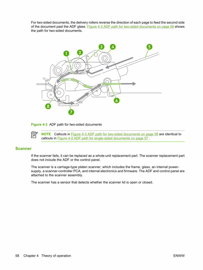
For two-sided documents, the delivery rollers reverse the direction of each page to feed the second sideof the document past the ADF glass. Figure 4-3 ADF path for two-sided documents on page 58 showsthe path for two-sided documents.
1 23 4 5
6
78
Figure 4-3 ADF path for two-sided documents
NOTE Callouts in Figure 4-3 ADF path for two-sided documents on page 58 are identical tocallouts in Figure 4-2 ADF path for single-sided documents on page 57 .
ScannerIf the scanner fails, it can be replaced as a whole-unit replacement part. The scanner replacement partdoes not include the ADF or the control panel.
The scanner is a carriage-type platen scanner, which includes the frame, glass, an internal power-supply, a scanner-controller PCA, and internal electronics and firmware. The ADF and control panel areattached to the scanner assembly.
The scanner has a sensor that detects whether the scanner lid is open or closed.
58 Chapter 4 Theory of operation ENWW

FormatterThe formatter is responsible for the following actions:
● Controlling the ADF/scanner assembly
● Formatting and controlling copies
● Receiving and processing print data from the computer interface
● Monitoring the control panel and relaying device status information
● Developing and coordinating data placement and timing with the print engine
Figure 4-4 Formatter connections on page 59 shows the formatter connections.
5
6
4
3
2
1 13
12
11
10
9
8
7
Figure 4-4 Formatter connections
1 Disk drive power 8 Network port
2 Disk drive interface 9 FIH port
3 ECU power 10 Type A Hi-Speed USB 2.0 connection for addingaccessories
4 ECU interface
5 ADF/scanner interface 11 Type B Hi-Speed USB 2.0 port
6 Control panel interface 12 DIMM slot
7 Fax accessory interface 13 EIO connection
ENWW Basic operation 59

Engine control unit (ECU)The ECU coordinates all device functions, according to commands that the formatter sends. It drivesthe laser/scanner system, the image formation system, and the pickup/feed/delivery system.
The ECU contains the following components:
● Engine-controller PCA
● Low-voltage PCA
Figure 4-5 Print engine general structure on page 60 shows the relationship of the ECU to the pickup/feed/delivery system, the laser/scanner system, and the image-formation system. Figure 4-6 Enginecontrol unit circuit diagram on page 61 provides the ECU circuit diagram. Figure 4-7 LVPS circuitdiagram on page 61 shows the low-voltage power supply circuit on the ECU.
METSYS RENNACS/RESALrorrim gninnacS
resaLedoid
Rear output bin
DBtiucric
rettamroF
DEEF/PUKCIPMETSYS
tinu gninaelC
Fuser
gnipoleveDtinu
EGAMINOITAMROF
METSYS
tinu deef xelpuD
refsnarTgnigrahc
rellor
rotom rennacS
-otohPevitisnes
murd
ECU
rellortnoc enignEACP
Tray 2tinu pukcip
Tray 1
Tray 1 pickup unit
Tray 2
yramirPgnigrahc
rellor
egatlov-hgiHACP ylppus rewoP
noitpO
Output bin
Figure 4-5 Print engine general structure
60 Chapter 4 Theory of operation ENWW

sdioneloS
noitpO
srotoM
gat yromeMlortnoc tiucric
egdirtraC
tinu userF
srosneS
egatlov-woLylppus rewop
tiucric
egatlov-hgiHylppus rewop
tiucric
rotom naFlortnoc evird
tiucricsnaF
sehctiwS
rosneS
srosneSUPC104CI
ECU
rotom rennacS
revird resaL
lortnoc FI oediVtiucric
egatlov-hgiHtiucric lortnoc
lortnoc resaLtiucric
rotom rennacStiucric lortnoc
lortnoc ecneuqeStiucric
rennacs/resaLtinu
Fusertiucric lortnoc
rettamroF
Figure 4-6 Engine control unit circuit diagram
NOTE Figure 6-11 ECU connections on page 268 shows the ECU connections.
Fuser heatercontrol circuit
ECU
Figure 4-7 LVPS circuit diagram
ENWW Basic operation 61

Pickup/feed/delivery systemThe pickup/feed/delivery system consists of several types of feed rollers and sensors. The ECU usestwo motors and two solenoids to drive the rollers. Three media-detection sensors detect media as itpasses through the device. If media does not reach or pass each sensor within a specified time period,the ECU determines that a jam has occurred and alerts the formatter.
The following components work together to feed media through the device:
● M1, main motor
● M2, fuser motor
● SL1, tray 1 pickup solenoid
● SL2, tray 2 pickup solenoid
● PS502, duplexer media-detection sensor
● Output-bin-full sensor
● PS901, top-of-page sensor
● PS902, tray 1 media-detection sensor
● PS903, media-width sensor
● SR1, top output-bin delivery flag
● SR2, fuser-delivery flag
Figure 4-8 Pickup/feed/delivery system block diagram
62 Chapter 4 Theory of operation ENWW
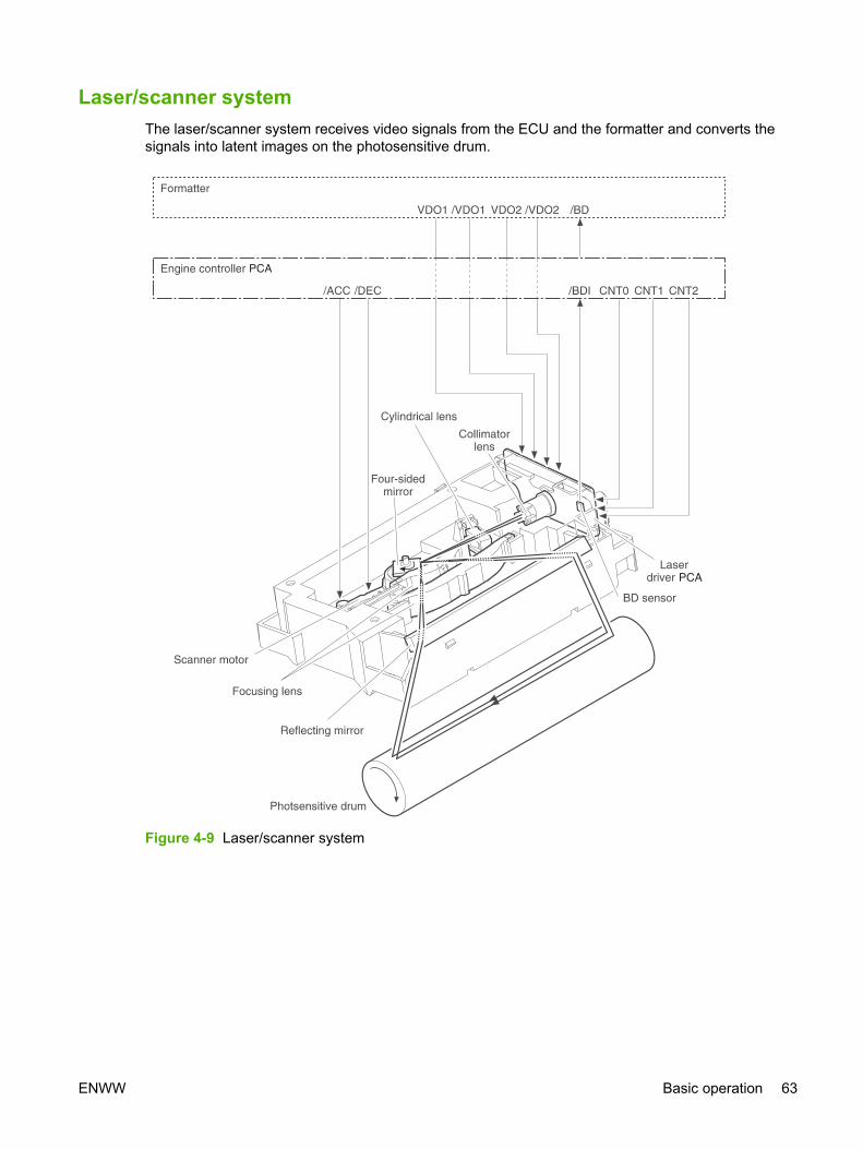
Laser/scanner systemThe laser/scanner system receives video signals from the ECU and the formatter and converts thesignals into latent images on the photosensitive drum.
Figure 4-9 Laser/scanner system
ENWW Basic operation 63

Image-formation systemLaser printing requires the interaction of several different technologies, including electronics, optics, andelectrophotographics, to provide a printed page.
Figure 4-10 Print cartridge diagram
Each process functions independently and must be coordinated with the other device processes. Imageformation consists of the following five processes:
● Electrostatic latent-image formation
● Developing
● Transfer
● Fusing
● Drum cleaning
The five processes contain eight steps, which are shown in the figureFigure 4-11 Image-formationsystem on page 64 and described in the following sections.
Figure 4-11 Image-formation system
64 Chapter 4 Theory of operation ENWW

Step 1: Primary chargingDc and ac biases are applied to the primary charging roller, which transfers a uniform negative potentialto the photosensitive drum.
Figure 4-12 Primary charging
Step 2: Laser beam exposureThe laser beam scans the photosensitive drum to neutralize negative charges on parts of the drum. Anelectrostatic latent image is formed on the drum where negative charges were neutralized.
Step 3: DevelopingThe developing cylinder comes in contact with the photosensitive drum to deposit toner onto theelectrostatic latent image.
NOTE The charges on the exposed area of the drum are shown as positive in Figure 4-13Developing on page 65. The charges are actually negative, but they are more positive than thecharges on the developing cylinder.
Figure 4-13 Developing
ENWW Basic operation 65

Toner acquires a negative charge through friction from the developing cylinder and the blade. When thenegatively charged toner comes in contact with the drum, the toner adheres to the electrostatic latentimage. The image on the drum becomes visible because of the toner.
Step 4: TransferThe transfer charging roller, to which a dc positive bias is applied, imparts a positive charge on the printmedia. When the print media comes in contact with the photosensitive drum, the toner is transferred tothe print media.
Media
Transfer roller
Photo-sensitive
drum
Figure 4-14 Transfer
Step 5: SeparationThe elasticity of the print media causes its separation from the photosensitive drum. A static chargeeliminator aids separation by weakening any electrostatic adhesion.
Figure 4-15 Separation
66 Chapter 4 Theory of operation ENWW

Step 6: FusingThe dc negative bias applied to the fusing film strengthens the holding force of the toner on the printmedia and prevents the toner from scattering.
Figure 4-16 Fusing
Step 7: Drum cleaningThe cleaning blade scrapes the residual toner off of the photosensitive drum and deposits it into thewaste toner case.
Figure 4-17 Drum cleaning
ENWW Basic operation 67

Internal componentsFigure 4-18 Cross-section of device on page 68 highlights the major internal components.
1 2 3 4 5 6 7 8
17 16 15 14 12 11 10 918 13Figure 4-18 Cross-section of device
1 Top output-bin delivery roller 10 Tray 2 separation pad
2 Fusing roller 11 Tray 2 pickup roller
3 Laser/scanner 12 Duplexer pickup roller
4 Photosensitive drum 13 Feed roller
5 Print cartridge 14 Transfer roller
6 Registration shutter 15 Duplexer feed roller
7 Tray 1 pickup roller 16 Oblique roller
8 Tray 1 separation pad 17 Fuser pressure-roller
9 Tray 2 feed roller 18 Fuser delivery-roller
68 Chapter 4 Theory of operation ENWW

TimingThe microprocessor on the ECU controls the device operation sequences. Table 4-1 Operationsequences on page 69 describes engine operations for each period of a print operation. Figure4-19 Operational sequences on page 70 provides a graphical representation of the operationsequences. Table 4-2 Power-on sequence on page 72 describes each step of the power-onsequence. Table 4-3 Power-on sequence for the ADF/scanner assembly on page 72 describes theADF power-on sequence.
Table 4-1 Operation sequences
Name Timing Purpose
WAIT From power-on until the end of the main motor initialdrive
Detects presence of a print cartridge. Clears potentialfrom the drum surface and cleans the transfer roller.
SeeTable 4-2 Power-on sequence on page 72 fora complete description of the WAIT (power-on)period. Also see Figure 4-20 Timing diagram,HP LaserJet M3027/M3035 on page 71 for detailedinformation about device timing.
STBY (standby) From the end of the WAIT or LSTR period until eithera print command is sent from the formatter or thepower is turned off.
Prepares the device to receive print commands
INTR (initialrotation)
From the time of the print command until the pickupsolenoid is turned on.
Prepares the photosensitive drum for printing.
PRINT From the end of the INTR period until the top-of-pagesensor detects the trailing edge of the media.
Forms the image on the photosensitive drum andtransfers the toner image to the media.
LSTR (lastrotation)
From the end of the PRINT period until the mainmotor stops rotating.
Delivers the last page of a print job.
After LSTR, the device either returns to STBY or, ifanother print command was sent from the formatter,enters INTR.
ENWW Timing 69
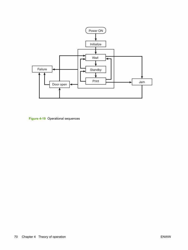
NO rewoP
ybdnatS
tnirP maJ
eruliaF
nepo rooD
ezilaitinI
tiaW
Figure 4-19 Operational sequences
70 Chapter 4 Theory of operation ENWW

1 2 3 4 5 6 7 8 9 10
11
12
13
14
15
16
17
18
19
20
ST
BY
WA
ITS
TB
YIN
TR
PR
INT
LS
TR
PrintC
om
mand
Main
Moto
r(M
1)
Fuser
Heate
r(H
1)
Fuser
Moto
r(M
2)
Scanner
Moto
r(M
3)
Cassette
Pic
kup
Sole
noid
(SL1)
Tra
y1
Pic
kup
Sole
noid
(SL2)
Paper
Feeder
Pic
kup
Sole
noid
(SL3)
Top
ofP
age
Sensor
(PS
801)
Deliv
ery
Sensor
(PS
803)
Prim
ary
Charg
ing
Bia
s(A
C)
Prim
ary
Charg
ing
Bia
s(D
C)
Develo
pin
gB
ias
(AC
)
Develo
pin
gB
ias
(DC
)
Tra
nsfe
rC
harg
ing
Bia
s
Laser
Dio
de
LA
SE
RB
EA
Msig
nal(B
D)
0.2
0.5
0.7
3.7
3.9
3.0
About1.3
9
About1.0
5A
bout1.4
6
0.0
90.2
3
0.8
0.3
4
0.2
7
1.5
0.7
8
About0.4
4
1.4
3
About0.7
About0.4
3.2
About1.2
0.0
90.2
3
0.1
60.1
60.2
30.2
3
0.4
7
0.2
0.5
About0.2
2
About0.2
2
About7.4
About1.5
About6.2
About3.3
Po
we
rS
witch
ON
SE
QU
EN
CE
12
0°C
Co
ntr
ol
Ne
ga
tive
Bia
s
12
0°C
Co
ntr
ol
Forc
ed
em
issio
n
(Unit:S
econds)
Figure 4-20 Timing diagram, HP LaserJet M3027/M3035
ENWW Timing 71
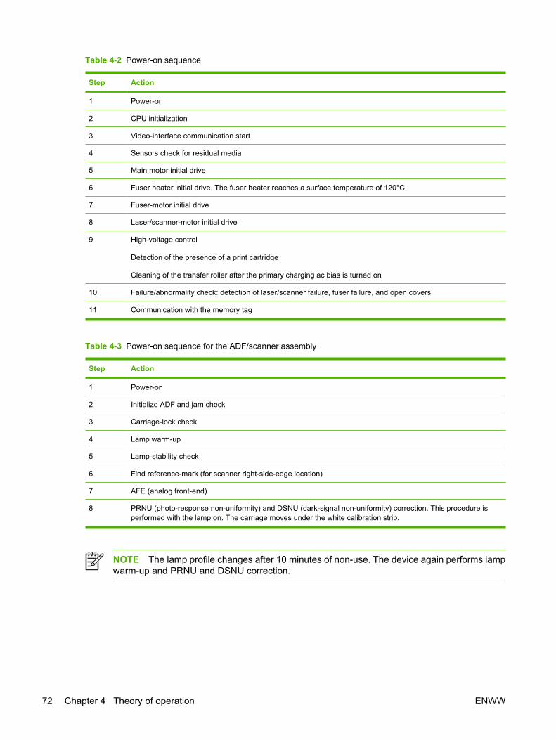
Table 4-2 Power-on sequence
Step Action
1 Power-on
2 CPU initialization
3 Video-interface communication start
4 Sensors check for residual media
5 Main motor initial drive
6 Fuser heater initial drive. The fuser heater reaches a surface temperature of 120°C.
7 Fuser-motor initial drive
8 Laser/scanner-motor initial drive
9 High-voltage control
Detection of the presence of a print cartridge
Cleaning of the transfer roller after the primary charging ac bias is turned on
10 Failure/abnormality check: detection of laser/scanner failure, fuser failure, and open covers
11 Communication with the memory tag
Table 4-3 Power-on sequence for the ADF/scanner assembly
Step Action
1 Power-on
2 Initialize ADF and jam check
3 Carriage-lock check
4 Lamp warm-up
5 Lamp-stability check
6 Find reference-mark (for scanner right-side-edge location)
7 AFE (analog front-end)
8 PRNU (photo-response non-uniformity) and DSNU (dark-signal non-uniformity) correction. This procedure isperformed with the lamp on. The carriage moves under the white calibration strip.
NOTE The lamp profile changes after 10 minutes of non-use. The device again performs lampwarm-up and PRNU and DSNU correction.
72 Chapter 4 Theory of operation ENWW

Print cartridge memory systemThe memory tag is a nonvolatile memory built into the print cartridge. The cartridge usage condition isdetected as the engine controller reads or writes the data stored on the memory tag. The enginecontroller renews the information in the prescribed timing and reads or writes it from or to the memorytag.
The engine controller commands the memory tag to read or write with the following conditions:
● Read
● Power is ON
● The top cover is closed
● A command has been received from the formatter
● Write
● A page of media is printed.
● A command has been received from the formatter
When the engine controller failed to read or write three times in a row, it determines that the memorytag is abnormal and notifies the formatter of a "cartridge memory abnormality warning".
Figure 4-21 Print cartridge memory tag
ENWW Print cartridge memory system 73

74 Chapter 4 Theory of operation ENWW

5 Removal and replacement
Chapter contents● Introduction
● Automatic document feeder (ADF) and scanner assemblies
● Covers
● Fax accessory
● Disk drive
● Formatter
● Stapler
● Stapler power-supply
● Right-side fan
● Engine control unit (ECU)
● Left-side riser
● Fuser
● Laser/scanner
● Access plate
● Oblique-roller assembly
● Left-side fan
● High-voltage power supply (HVPS)
● Feed-guide assembly
● Main motor
● Gear assembly
● Reinstallation notes for the gear assembly
● Tray 1 solenoid
● Tray 2 solenoid
ENWW Chapter contents 75

● Pickup assembly
● Tray 1 media-present sensor and top-of-page sensor
● E-label reader (memory tag)
● Face-down-roller shaft
● Cartridge door
● Transfer roller
● Registration assembly
● Tray 1 pickup roller
● Tray 2 pickup roller
● Separation pad
76 Chapter 5 Removal and replacement ENWW

IntroductionThis chapter documents removal and replacement of field replaceable units (FRUs) only.
Removal and replacement strategy Replace parts in the reverse order of their removal. Directions for difficult or critical replacementprocedures are included.
WARNING! The sheet-metal edges of the device can be sharp. Use caution when working onthe device.
NOTE Note the length, diameter, color, type, and location of each screw. Be sure to return eachscrew to its original location during reassembly.
Incorrectly routed or loose cables can interfere with other internal components and can becomedamaged or broken. Frayed or pinched cables can be difficult to locate. When reconnecting thecables, always use the provided wire loops, lance points, or cable guides.
Electrostatic discharge
CAUTION The device contains parts that are sensitive to electrostatic discharge (ESD). Alwaysservice the device at an ESD-protected workstation, or use an ESD mat.
Watch for the ESD symbol (shown at left) to identify the parts that are sensitive to ESD. Protect theseparts by using an ESD wrist strap and by placing ESD-sensitive parts into protective ESD pouches.
User-replaceable partsTo remove and replace the pickup roller or separation pad, see Separation pad on page 189.
ENWW Introduction 77

Required toolsThe following tools are needed to service this device:
● #2 Phillips screwdriver with magnetic tip
● Short Phillips screwdriver with magnetic tip (also known as a “stubby” screwdriver)
● Small flat-blade screwdriver
● Small needle-nose pliers
● ESD mat
● Small flashlight
CAUTION A pozidriv screwdriver will damage screw heads on the device. Use a #2 Phillipsscrewdriver.
If you use a multispeed screwdriver, use a torque limiter.
Before performing serviceFollow the pre-service procedures before you perform service.
Pre-service procedures
1. Remove all media from the device.
2. Place the device on an ESD mat. If an ESD mat or an ESD-protected workstation is not available,discharge body static and ground the device chassis before servicing the device.
3. Unplug the power cord and the interface cable.
4. Lift the device off of any installed optional trays.
5. Remove the print cartridge.
CAUTION To prevent light from degrading the surface of the photosensitive drum, coverthe print cartridge after removing it from the device.
6. Remove tray 2.
78 Chapter 5 Removal and replacement ENWW

Parts removal orderEach section contains a list of covers and assemblies that have to be removed before working on themajor assembly that is the subject of the section.
Control panelAutomatic document feeder (ADF)Transfer rollerTray 1 pickup rollerTray 2 pickup rollerRight-side cover
Formatter shieldDisk drive
FormatterFax cover
Left-side coverBack cover
I/O coverFuserAccess plate
Oblique-roller assemblyADF/scanner assembly
Fax accessoryRegistration assemblyStapler
Back coverI/O cover
Fax railTop coverFax accessory
Disk driveFormatter
Stapler power-supplyFront, right cover
Right-side fanCartridge door
All covers and the ADF/scanner assemblyLeft-side riserLaser/scannerE-label readerFace-down-roller shaftLeft-side fanFax accessory
Disk driveFormatter
StaplerStapler power-supply
Right-side fanECU
Tray 1 solenoidLeft-side riser
Access plateOblique-roller assembly
Left-side fanHigh-voltage power supply (HVPS)
Feed-guide assemblyMain motorGear assembly
Tray 2 solenoidPickup assembly
Tray 1 media-present sensorTop-of-page sensor
Figure 5-1 Parts removal diagram
ENWW Introduction 79

Automatic document feeder (ADF) and scanner assembliesAutomatic document feeder (ADF) and scanner assemblies
ADF assemblyThe ADF cover and the ADF input tray need not be removed unless they require service.
ADF cover1. Open the ADF cover.
2. Rotate the ADF cover firmly toward the left side of the device and down to release three tabs(callout 1).
Figure 5-2 Removing the ADF cover
80 Chapter 5 Removal and replacement ENWW

Figure 5-3 Reinstalling the ADF cover
Reinstallation tip When reinstalling the ADF cover, firmly press the three tabs until they clickinto place. When the three tabs are installed correctly, the cover should close easily. If it doesnot, open the ADF cover and check the tabs. Do not force the ADF cover closed. Forcing theADF cover closed can damage the cover.
ENWW Automatic document feeder (ADF) and scanner assemblies 81

ADF input tray1. Open the ADF cover.
2. Pull the ADF input tray up firmly to release one tab (callout 1).
1
Figure 5-4 Removing the ADF input tray
82 Chapter 5 Removal and replacement ENWW

Figure 5-5 Reinstalling the ADF input tray
Reinstallation tip When reinstalling the ADF input tray, slide the tray straight into place. ADFjams and skew can result from incorrect reinstallation.
ENWW Automatic document feeder (ADF) and scanner assemblies 83

Control panel1. Insert a flat-blade screwdriver into the gap at the left side of the control panel to disengage the
control panel and then lift up the front of the control panel.
Figure 5-6 Removing the control panel (1 of 2)
84 Chapter 5 Removal and replacement ENWW

2. Disconnect one cable (callout 1).
1
Figure 5-7 Removing the control panel (2 of 2)
3. Lift the control panel off of the device.
ENWW Automatic document feeder (ADF) and scanner assemblies 85

2
Figure 5-8 Reinstalling the control panel
Reinstallation tip Make sure that you insert the tabs at the back of the control panel (callout 2)into the slots.
86 Chapter 5 Removal and replacement ENWW

ADF1. Unscrew the thumb screws (callout 1) on the ADF cable at the back of the device and then unplug
the cable.
1
Figure 5-9 Removing the ADF (1 of 3)
ENWW Automatic document feeder (ADF) and scanner assemblies 87

2. Lift the ADF lid and then press the hinge-release tab (callout 2) toward the right side of the device.
2
Figure 5-10 Removing the ADF (2 of 3)
88 Chapter 5 Removal and replacement ENWW

3. Lift the ADF off of the device.
Figure 5-11 Removing the ADF (3 of 3)
ENWW Automatic document feeder (ADF) and scanner assemblies 89

Scanner assembly
NOTE If you are not replacing the scanner assembly, but need to remove it in order to gainaccess to assemblies inside the printer portion of the device, you can remove the scannerassembly and ADF together. To remove the scanner assembly and ADF together, begin thisprocedure with step 2.
1. Remove the ADF (see ADF assembly on page 80).
2. Remove the right-side cover (see Right-side cover on page 94), the formatter shield (seeFormatter shield on page 95), the fax cover (see Fax cover on page 96), and the left-side cover(see Left-side cover on page 97).
3. Remove one cable from the cable guide (callout 1) and then disconnect the cable (callout 2) fromthe formatter.
CAUTION Failure to remove the cable from the cable guide can cause damage to thecable.
4. Disconnect the ribbon cable (callout 3) and then separate the power-cable connector (callout 4).
1
2
4
3
Figure 5-12 Removing the scanner assembly (1 of 4)
90 Chapter 5 Removal and replacement ENWW

5. Remove one screw (callout 5) at the left side and two screws (callouts 6 and 7) at the back of thedevice.
5
7
6
Figure 5-13 Removing the scanner assembly (2 of 4)
ENWW Automatic document feeder (ADF) and scanner assemblies 91
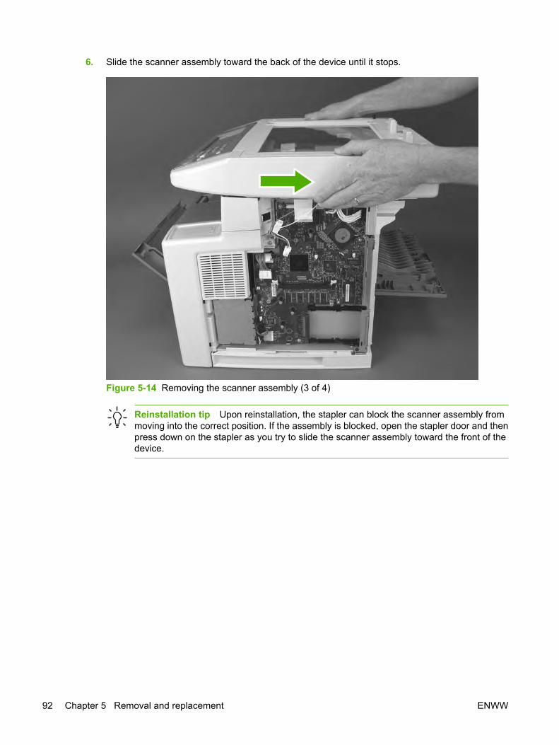
6. Slide the scanner assembly toward the back of the device until it stops.
Figure 5-14 Removing the scanner assembly (3 of 4)
Reinstallation tip Upon reinstallation, the stapler can block the scanner assembly frommoving into the correct position. If the assembly is blocked, open the stapler door and thenpress down on the stapler as you try to slide the scanner assembly toward the front of thedevice.
92 Chapter 5 Removal and replacement ENWW

7. Lift the assembly straight up and off of the device.
Figure 5-15 Removing the scanner assembly (4 of 4)
ENWW Automatic document feeder (ADF) and scanner assemblies 93

CoversNot all covers have to be removed to get to various FRUs. Use the list provided in each section todetermine which covers and other components must be removed.
Right-side cover1. Slide the right-side cover toward the back of the device.
Figure 5-16 Removing the right-side cover
2. Lift the cover away from the device.
94 Chapter 5 Removal and replacement ENWW

Formatter shield1. Remove the right-side cover (see Right-side cover on page 94).
2. Rotate the formatter shield away from the front of the device, and then lift it off of its hinges (callout 1)at the back of the device.
1
Figure 5-17 Removing the formatter shield
ENWW Covers 95

Fax coverPull the fax cover away from the back of the device.
Figure 5-18 Removing the fax cover
96 Chapter 5 Removal and replacement ENWW
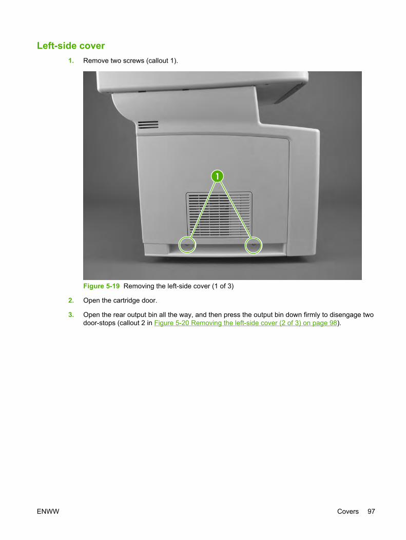
Left-side cover1. Remove two screws (callout 1).
1
Figure 5-19 Removing the left-side cover (1 of 3)
2. Open the cartridge door.
3. Open the rear output bin all the way, and then press the output bin down firmly to disengage twodoor-stops (callout 2 in Figure 5-20 Removing the left-side cover (2 of 3) on page 98).
ENWW Covers 97

4. Use a flat-blade screwdriver to press one tab (callout 3) toward the back of the device, and thenrotate the cover away from the back of the device.
2
3
Figure 5-20 Removing the left-side cover (2 of 3)
98 Chapter 5 Removal and replacement ENWW

5. Slide the cover toward the front of the device to clear tabs at the front (callout 4), and then lift thecover away from the device.
4
Figure 5-21 Removing the left-side cover (3 of 3)
ENWW Covers 99

Legal cover (dust cover)1. Rotate the cover up to the horizontal position.
2. Flex the middle of the cover until one of the hinges is released from its slot.
3. Slide the cover toward the released hinge to release the other hinge.
100 Chapter 5 Removal and replacement ENWW

Back cover1. Remove the left-side cover (see Left-side cover on page 97) and leave the rear output bin all the
way open.
2. Remove two screws (callout 1).
1
Figure 5-22 Removing the back cover (1 of 2)
ENWW Covers 101

3. Release one tab (callout 2) inside the device and then rotate the bottom of the cover away fromthe device.
2
Figure 5-23 Removing the back cover (2 of 2)
4. Lift the cover away from the device.
102 Chapter 5 Removal and replacement ENWW

I/O cover1. Remove the back cover (see Back cover on page 101).
2. Rotate the I/O cover to clear tabs at the right side of the cover.
Figure 5-24 Removing the I/O cover
3. Lift the cover off of the device.
ENWW Covers 103

Fax rail1. Remove the following components:
● Right-side cover (see Right-side cover on page 94)
● Formatter shield (see Formatter shield on page 95)
● Fax cover (see Fax cover on page 96)
● Left-side cover (see Left-side cover on page 97)
● Back cover (see Back cover on page 101)
● I/O cover (see I/O cover on page 103)
● ADF/scanner assembly (see Scanner assembly on page 90)
2. Remove two screws (callout 1).
1
Figure 5-25 Removing the fax rail
3. Lift the fax rail off of the device.
104 Chapter 5 Removal and replacement ENWW

Top cover1. Remove the following components:
● Right-side cover (see Right-side cover on page 94)
● Formatter shield (see Formatter shield on page 95)
● Fax cover (see Fax cover on page 96)
● Left-side cover (see Left-side cover on page 97)
● Back cover (see Back cover on page 101)
● I/O cover (see I/O cover on page 103)
● ADF/scanner assembly (see Scanner assembly on page 90)
● Fax rail (see Fax rail on page 104)
2. Remove two screws (callout 1) from each side of the device (a total of four screws).
1
Figure 5-26 Removing the top cover (1 of 3)
ENWW Covers 105

3. Squeeze the cover at the back of the device to release two tabs and lift up the cover slightly.
Figure 5-27 Removing the top cover (2 of 3)
106 Chapter 5 Removal and replacement ENWW

4. Slide the cover toward the front of the device to clear the tabs (callout 2) at the front of the device.
2
3
Figure 5-28 Removing the top cover (3 of 3)
5. Lift the cover off of the device.
Reinstallation tip The grounding connection (callout 3) can become caught in the chassiswhen lifting the cover. Make sure that it is still attached to the cover before you reinstall the cover.
ENWW Covers 107

4
Figure 5-29 Reinstalling the top cover
Reinstallation tip After reinstalling the cover, make sure that the exit-sensor flag (callout 4)moves freely.
108 Chapter 5 Removal and replacement ENWW

Front, right cover1. Remove the right-side cover (see Right-side cover on page 94).
2. Remove two screws (callout 1).
1
Figure 5-30 Removing the front, right cover (1 of 2)
ENWW Covers 109

3. Rotate the cover away from the back of the device to clear two tabs (callout 2) at the front of thedevice.
2
Figure 5-31 Removing the front, right cover (2 of 2)
4. Lift the cover away from the device.
110 Chapter 5 Removal and replacement ENWW

Fax accessory1. Remove the following components:
● Right-side cover (see Right-side cover on page 94)
● Formatter shield (see Formatter shield on page 95)
● Fax cover (see Fax cover on page 96)
● ADF/scanner assembly (see Scanner assembly on page 90)
2. Disconnect one cable (callout 1) from the fax accessory.
1
Figure 5-32 Removing the fax accessory (1 of 2)
ENWW Fax accessory 111

3. Slide the fax accessory toward the back and out of the device.
Figure 5-33 Removing the fax accessory (2 of 2)
112 Chapter 5 Removal and replacement ENWW

Disk drive1. Remove the right-side cover (see Right-side cover on page 94) and the formatter shield (see
Formatter shield on page 95).
2. Disconnect two cables (callout 1) and remove one screw (callout 2).
2
1
Figure 5-34 Removing the disk drive (1 of 3)
3. Slide the disk drive up slightly to clear three tabs from the tab slots (callout 3 in Figure 5-35Removing the disk drive (2 of 3) on page 114), and then lift the disk drive away from the device.
Reinstallation tip Upon reinstallation, make sure that all three tabs are inserted correctlyinto the slots. Also make sure that the screw-hole tab on the disk drive housing is on top ofthe tab in the device.
NOTE If you are replacing the disk drive, complete the additional steps below. If you areremoving the disk drive in order to replace the formatter or other parts, there is no need tocomplete the remaining steps in this section.
ENWW Disk drive 113

4. Remove two screws (callout 4) from the metal housing.
3
4
Figure 5-35 Removing the disk drive (2 of 3)
114 Chapter 5 Removal and replacement ENWW

5. Open the metal-housing door, remove the disk drive from the metal housing, and then disconnecttwo cables (callout 5).
5
Figure 5-36 Removing the disk drive (3 of 3)
ENWW Disk drive 115

Formatter1. Remove the following components:
● Right-side cover (see Right-side cover on page 94)
● Formatter shield (see Formatter shield on page 95)
● Disk drive (see Disk drive on page 113)
NOTE Removing the disk drive is not a required step. However, you might find iteasier to remove the formatter if you have already removed the disk drive.
2. Disconnect three cables (callout 1) from the top of the formatter.
3. Disconnect four cables (callout 2) from the left side (toward the front of the device) of the formatter.
4. Remove six screws (callout 3).
1
3
2
Figure 5-37 Removing the formatter
5. Lift up the formatter slightly to clear one tab at the bottom, rotate the left edge of the formatter (atthe front of the device) away from the device, and then slide the formatter toward the front of thedevice to remove it.
116 Chapter 5 Removal and replacement ENWW

Stapler1. Remove the following components:
● Right-side cover (see Right-side cover on page 94)
● Formatter shield (see Formatter shield on page 95)
● Fax cover (see Fax cover on page 96)
● Left-side cover (see Left-side cover on page 97)
● ADF/scanner assembly (see Scanner assembly on page 90)
2. Remove one screw (callout 1) from the stapler cover and then lift the cover off of the device.
1
Figure 5-38 Removing the stapler (1 of 3)
ENWW Stapler 117
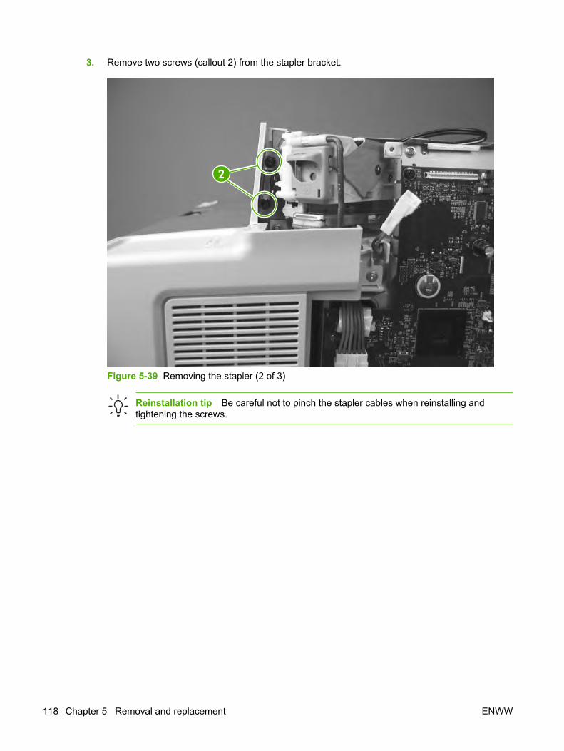
3. Remove two screws (callout 2) from the stapler bracket.
2
Figure 5-39 Removing the stapler (2 of 3)
Reinstallation tip Be careful not to pinch the stapler cables when reinstalling andtightening the screws.
118 Chapter 5 Removal and replacement ENWW

4. Lift the stapler out of the device and then disconnect one cable (callout 3) from the back of thestapler.
3
Figure 5-40 Removing the stapler (3 of 3)
ENWW Stapler 119

4
5
Figure 5-41 Reinstalling the stapler (1 of 3)
Reinstallation tip For correct placement, insert the metal tab at the back of the stapler(callout 4) into the slot in the chassis (callout 5). The following figure shows correct placement ofthe metal tab in callout 6 and incorrect placement of the metal tab in callout 7.
6 7
Figure 5-42 Reinstalling the stapler (2 of 3) – correct (callout 6) and incorrect (callout 7) reinstallationof the metal tab.
120 Chapter 5 Removal and replacement ENWW

8
Figure 5-43 Reinstalling the stapler (3 of 3)
Reinstallation tip Make sure that the actuator rod (callout 8) is inserted into the hole in thestapler and that it moves freely.
Stapler testing – to be performed after the device is fully reassembled
WARNING! Incorrect reinstallation of the stapler can cause the stapler-door switch to operateincorrectly, resulting in a safety hazard. Test the stapler for correct operation before releasingthe device back to the customer.
Final stapler-test procedure
Test #1: Does the stapler operate correctly when the stapler door is closed?
With the stapler door closed, use the stapler to staple several sheets of paper together. The staplershould staple the sheets.
Test #2 (safety-switch test): Does the stapler operate when the stapler door is open?
Open the stapler door and attempt to use the stapler to staple several sheets of paper together. Whenthe stapler and stapler door safety-switch are operating correctly, the open door cuts power to the staplerand the stapler does not staple the sheets.
ENWW Stapler 121

WARNING! Do not release the device back to the customer unless the stapler passes both ofthe tests. If the stapler fails either test, remove the stapler and then reinstall it by carefully followingthe installation steps shown in this manual. If the stapler continues to fail one or both tests, replacethe stapler and the stapler power supply.
If the staple activates when the stapler door is open, and the stapler cannot be repaired withoutordering parts, disconnect the stapler power supply before reassembling the device and beforeyou leave the customer site. When the stapler power supply is disconnected, the customer cansafely operate all device functions, except for stapling, while waiting for repair of the stapler.
122 Chapter 5 Removal and replacement ENWW

Stapler power-supply1. Remove the following components:
● All covers except for the top cover and the right, front cover (see Covers on page 94)
● ADF/scanner assembly (see Scanner assembly on page 90)
● Fax accessory (see Fax accessory on page 111)
● Formatter (see Formatter on page 116)
● Stapler (see Stapler on page 117)
2. Remove two screws (callout 1) from the side of the I/O plate and one screw (callout 2) from theback of the plate.
1
2
Figure 5-44 Removing the stapler power supply (1 of 5)
ENWW Stapler power-supply 123

3. Lift the I/O plate up slightly to dislodge it from the tabs (callout 3) on the ECU plate, and then slideit toward the back and off of the device.
3
Figure 5-45 Removing the stapler power supply (2 of 5)
124 Chapter 5 Removal and replacement ENWW

4. Remove three screws (callout 4) from the stapler-power-supply plate.
4
Figure 5-46 Removing the stapler power supply (3 of 5)
ENWW Stapler power-supply 125

5. Slide the stapler-power-supply plate toward the back of the device until it stops, and then guidecables through a hole in the stapler-power-supply plate while lifting the plate straight away fromthe device.
Figure 5-47 Removing the stapler power supply (4 of 5)
Reinstallation tip Guide the cables through the hole in the stapler-power-supply platebefore attaching the plate.
126 Chapter 5 Removal and replacement ENWW

6. Unplug the power-supply cable (callout 5) and then remove one screw (callout 6) to release thepower-supply cover.
6
5
Figure 5-48 Removing the stapler power supply (5 of 5)
7. Lift the cover off of the power supply and then lift the power supply off of the plate.
ENWW Stapler power-supply 127

Right-side fan1. Remove the following components:
● All covers except for the top cover (see Covers on page 94)
● ADF/scanner assembly (see Scanner assembly on page 90)
● Fax accessory (see Fax accessory on page 111)
● Disk drive (see Disk drive on page 113)
● Formatter (see Formatter on page 116)
● Stapler (see Stapler on page 117) and stapler power-supply (see Stapler power-supplyon page 123)
2. Remove the grounding wire (callout 1) from the fan housing.
1
Figure 5-49 Removing the right-side fan (1 of 3)
128 Chapter 5 Removal and replacement ENWW

3. Remove three screws (callout 2) from the clip-tray/stapler housing assembly and then lift theassembly off of the device.
2
3
Figure 5-50 Removing the right-side fan (2 of 3)
Reinstallation tip When reinstalling the clip-tray/stapler-housing assembly, route thescanner power cable (callout 3) through an opening in the assembly.
ENWW Right-side fan 129

4. Disconnect the fan cable (callout 4) at the ECU and then remove two screws (callout 5).
5
4
Figure 5-51 Removing the right-side fan (3 of 3)
5. Slide the fan out of the device.
130 Chapter 5 Removal and replacement ENWW

Engine control unit (ECU)1. Remove the following components:
● All of the covers (see Covers on page 94) and the ADF/scanner assembly (see Scannerassembly on page 90)
● Fax accessory (see Fax accessory on page 111)
● Disk drive (see Disk drive on page 113)
● Formatter (see Formatter on page 116)
● Stapler (see Stapler on page 117) and stapler power-supply (see Stapler power-supplyon page 123)
● Right-side fan (see Right-side fan on page 128)
2. Disconnect ten cables (callout 1) from the ECU.
3. Remove two screws (callout 2—one from the right-side riser and one from the ECU plate).
2
1
Figure 5-52 Removing the ECU (1 of 6)
ENWW Engine control unit (ECU) 131
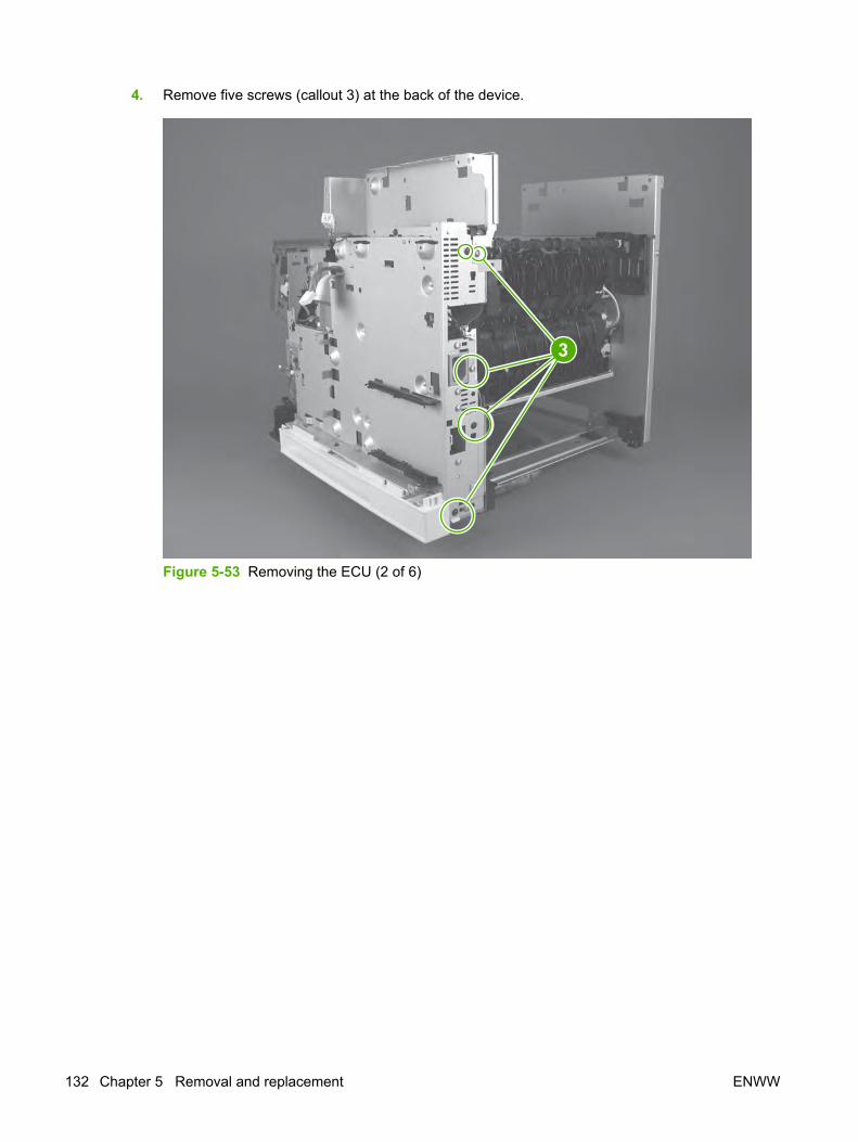
4. Remove five screws (callout 3) at the back of the device.
3
Figure 5-53 Removing the ECU (2 of 6)
132 Chapter 5 Removal and replacement ENWW

5. Remove three screws (callout 4) from the right-side riser and then lift the riser off of the device.Also remove two screws (callout 5) from the ECU plate.
4
5
Figure 5-54 Removing the ECU (3 of 6)
ENWW Engine control unit (ECU) 133

6. Disconnect two sensor cables (callout 6) and the fuser power cable (callout 7).
6
7
Figure 5-55 Removing the ECU (4 of 6)
134 Chapter 5 Removal and replacement ENWW

7. Unplug the laser/scanner ribbon cable (callout 8) from the laser/scanner and disconnect one inlineconnector (callout 9). Then, unwind the front-door microswitch cable from the cable guides andthen remove the microswitch (callout 10) from its housing.
9
10
Figure 5-56 Removing the ECU (5 of 6)
Figure 5-57 Reinstalling the front-door microswitch cable
Reinstallation tip Upon reinstallation, replace the microswitch in its housing and thenroute the cable as shown in Figure 5-57 Reinstalling the front-door microswitch cableon page 135.
ENWW Engine control unit (ECU) 135

8. Lift up the ECU slightly and rotate the top of the ECU away from the device. After it is rotated,disconnect one ribbon cable (callout 11) from the ECU.
11
Figure 5-58 Removing the ECU (6 of 6)
9. Lift the ECU off of the device.
NOTE The ECU and the ECU pan together are a single FRU. You do not have to separate theECU and the ECU pan.
136 Chapter 5 Removal and replacement ENWW

12
13
Figure 5-59 Reinstalling the ECU
Reinstallation tip Make sure that the power switch (callout 12) fits into the correct position inthe switch link (callout 13).
ENWW Engine control unit (ECU) 137

Left-side riser1. Remove all covers (see Covers on page 94) and the ADF/scanner assembly (see Scanner
assembly on page 90)
2. Remove four screws (callout 1).
1
Figure 5-60 Removing the left-side riser
3. Lift the left-side riser off of the device.
138 Chapter 5 Removal and replacement ENWW

Fuser1. Remove the back cover (see Back cover on page 101) and the I/O cover (see I/O cover
on page 103).
2. Remove the duplexer inlet guide by releasing two tabs (callout 1) on the guide, and then slidingthe guide toward the back of the device.
1
Figure 5-61 Removing the fuser (1 of 3)
Reinstallation tip Make sure that both tabs snap into place when reinstalling the duplexerinlet guide.
ENWW Fuser 139

3. Disconnect the fuser power cable (callout 2) and remove the cable from the cable guide (callout 3).Also disconnect two cables (callout 4) at the right side of the fuser and remove one of the cablesfrom the cable guide (callout 5).
3
2
5
4
Figure 5-62 Removing the fuser (2 of 3)
140 Chapter 5 Removal and replacement ENWW
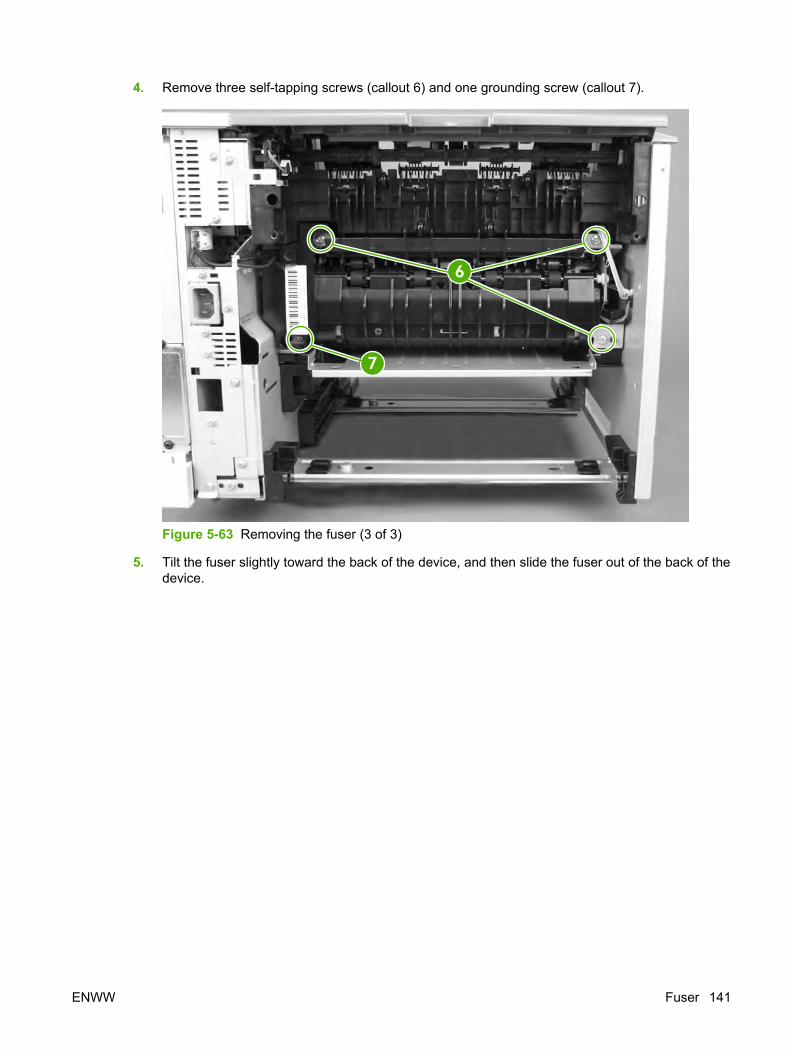
4. Remove three self-tapping screws (callout 6) and one grounding screw (callout 7).
6
7
Figure 5-63 Removing the fuser (3 of 3)
5. Tilt the fuser slightly toward the back of the device, and then slide the fuser out of the back of thedevice.
ENWW Fuser 141

Laser/scanner1. Remove all covers (see Covers on page 94) and the ADF/scanner assembly (see Scanner
assembly on page 90).
2. Release one tab (callout 1) on the air duct, and then lift the air duct out of the device.
1
Figure 5-64 Removing the laser/scanner (1 of 2)
142 Chapter 5 Removal and replacement ENWW

3. Disconnect two cables (callout 2) and then remove four screws (callout 3).
Figure 5-65 Removing the laser/scanner (2 of 2)
4. Lift the laser/scanner out of the device.
ENWW Laser/scanner 143

Access plate1. Remove the following components:
● Left-side cover (see Left-side cover on page 97)
● Back cover (see Back cover on page 101)
● I/O cover (see I/O cover on page 103)
● Duplexer inlet guide (see Figure 5-61 Removing the fuser (1 of 3) on page 139)
2. At the front of the device, push the green button on the top, right front of the tray 2 opening torelease the access plate.
Figure 5-66 Removing the access plate (1 of 2)
144 Chapter 5 Removal and replacement ENWW

3. At the back of the device, press one tab (callout 1) to release the access plate, and then lower theaccess plate until the other side slides off of the other tab (callout 2).
NOTE You might have to pry the tab with a flat-blade screwdriver. If you bend the tab,straighten the tab before you reinstall the plate.
1
2
Figure 5-67 Removing the access plate (2 of 2)
4. Slide the plate out of the device.
CAUTION Make sure that you do not damage the spring that is attached to the plate.
ENWW Access plate 145

Oblique-roller assembly1. Remove the following components:
● Left-side cover (see Left-side cover on page 97)
● Back cover (see Back cover on page 101)
● I/O cover (see I/O cover on page 103)
● Duplexer inlet guide (see Figure 5-61 Removing the fuser (1 of 3) on page 139)
● Access plate (see Access plate on page 144)
2. At the bottom of the device, remove the two screws (callout 1) that secure the oblique-rollerassembly to the device, and then lift the assembly from the device.
1
Figure 5-68 Removing the oblique-roller assembly
146 Chapter 5 Removal and replacement ENWW

3
2
Figure 5-69 Reinstalling the oblique-roller assembly
Reinstallation tip To reinstall the oblique-roller assembly, first make sure that the tab (callout 2)is parallel to the assembly. Then line up the the roller shaft (callout 3) with its hole on the assemblyand rotate the assembly into place. Rotate the roller toward the back of the device to align thegears.
ENWW Oblique-roller assembly 147

Left-side fan1. Remove all of the covers (see Covers on page 94) and the ADF/scanner assembly (see Scanner
assembly on page 90).
2. Disconnect the left-side-fan cable from the ECU.
3. Remove two screws (callout 1) at the left side of the device and then lift the fan plate and fan straightaway from the hole in the chassis.
NOTE Do not disconnect the left-side-fan cable from the fan. Instead, unroute the fan cablestarting at the ECU connector.
1
Figure 5-70 Removing left-side fan
148 Chapter 5 Removal and replacement ENWW

High-voltage power supply (HVPS)1. Remove the following components:
● All covers (see Covers on page 94) and the ADF/scanner assembly (see Scannerassembly on page 90)
● Fax accessory (see Fax accessory on page 111)
● Disk drive (see Disk drive on page 113)
● Formatter (see Formatter on page 116)
● Stapler (see Stapler on page 117) and stapler power-supply (see Stapler power-supplyon page 123)
● ECU (see Engine control unit (ECU) on page 131)
● Left-side riser (see Left-side riser on page 138)
● Access plate (see Access plate on page 144)
● Oblique-roller assembly (see Oblique-roller assembly on page 146)
● Left-side fan (see Left-side fan on page 148)
Tip You do not have to unroute the left-side-fan cable in order to remove the HVPS.After removing the fan from its hole in the chassis, simply set the fan down on theworkspace.
2. Tip the device so that it rests on its top.
ENWW High-voltage power supply (HVPS) 149

3. Remove one grounding screw from inside the slot (callout 1) for the flat ribbon cable.
1
Figure 5-71 Removing the HVPS (1 of 5)
150 Chapter 5 Removal and replacement ENWW

4. At the left side of the device, disconnect one cable (callout 2) and then remove two screws(callout 3).
2
3
Figure 5-72 Removing the HVPS (2 of 5)
Reinstallation tip Remember how the cable is threaded and connected to the device.
ENWW High-voltage power supply (HVPS) 151

5. Remove two screws (callout 4) from the ribbon-cable protector (callout 5) and then lift the protectorout of the device.
4
5
Figure 5-73 Removing the HVPS (3 of 5)
152 Chapter 5 Removal and replacement ENWW

6. Guide the ribbon cable (callout 6) through the hole in the chassis and then remove the remainingthree screws (callout 7) from the HVPS pan.
6
7
Figure 5-74 Removing the HVPS (4 of 5)
ENWW High-voltage power supply (HVPS) 153

7. Lift the edge of the HVPS pan and then disconnect two cables (callout 8) from the HVPS.
8
Figure 5-75 Removing the HVPS (5 of 5)
NOTE The HVPS pan and the HVPS together are a single FRU. You do not have to separatethe HVPS from the pan.
154 Chapter 5 Removal and replacement ENWW

9
Figure 5-76 Grounding-spring locations
Reinstallation tip As you remove the power supply, note the locations of the grounding springs.You might need to reinstall one non-captive spring (callout 9) before reinstalling the power supply.
ENWW High-voltage power supply (HVPS) 155

Feed-guide assembly1. Remove the following components:
● All of the covers (see Covers on page 94) and the ADF/scanner assembly (see Scannerassembly on page 90)
● Fax accessory (see Fax accessory on page 111)
● Disk drive (see Disk drive on page 113)
● Formatter (see Formatter on page 116)
● Stapler (see Stapler on page 117) and stapler power-supply (see Stapler power-supplyon page 123)
● ECU (see Engine control unit (ECU) on page 131)
● Left-side riser (see Left-side riser on page 138)
● Access plate (see Access plate on page 144)
● Fuser (see Fuser on page 139)
● Oblique-roller assembly (see Oblique-roller assembly on page 146)
● Left-side fan (see Left-side fan on page 148)
Tip You do not have to unroute the left-side-fan cable in order to remove the HVPSor the feed-guide assembly. After removing the fan from its hole in the chassis, simplyset the fan down on the workspace.
● High-voltage power supply (see High-voltage power supply (HVPS) on page 149)
2. Lift one non-captive grounding spring (see callout 9 in Figure 5-76 Grounding-spring locationson page 155) out of the device.
3. Loosen the grounding wire from the routing guides (see callout 1 in Figure 5-77 Removing the feed-guide assembly (1 of 2) on page 157).
CAUTION Do not bend or remove the grounding wire.
156 Chapter 5 Removal and replacement ENWW

4. Remove two screws (callout 2).
2
1
Figure 5-77 Removing the feed-guide assembly (1 of 2)
ENWW Feed-guide assembly 157

5. On the edge of the assembly that is farthest from you, lift the right corner up, twist the assemblycounterclockwise, and remove the assembly from the device.
Figure 5-78 Removing the feed-guide assembly (2 of 2)
Reinstallation tip Make sure that the loosened grounding wire is out of the way beforereinstalling the feed-guide assembly.
158 Chapter 5 Removal and replacement ENWW

Main motor1. Remove the following components:
● All of the covers (see Covers on page 94) and the ADF/scanner assembly (see Scannerassembly on page 90)
● Fax accessory (see Fax accessory on page 111)
● Disk drive (see Disk drive on page 113)
● Formatter (see Formatter on page 116)
● Stapler (see Stapler on page 117) and stapler power-supply (see Stapler power-supplyon page 123)
● ECU (see Engine control unit (ECU) on page 131)
● Left-side riser (see Left-side riser on page 138)
● Access plate (see Access plate on page 144)
● Fuser (see Fuser on page 139)
● Oblique-roller assembly (see Oblique-roller assembly on page 146)
● Left-side fan (see Left-side fan on page 148)
Tip You do not have to unroute the left-side-fan cable in order to remove the HVPS,the feed-guide assembly, or the main motor. After removing the fan from its hole in thechassis, simply set the fan down on the workspace.
● High-voltage power supply (see High-voltage power supply (HVPS) on page 149)
● Feed-guide assembly (see Feed-guide assembly on page 156)
ENWW Main motor 159

2. Remove three screws (callout 1) from the main motor cover and then lift the cover out of the device.
1
Figure 5-79 Removing the main motor (1 of 2)
WARNING! The teeth on the static-eliminator sheet are sharp. Be careful not to cutyourself on the static-eliminator teeth when removing screws in the area of the main motor.
160 Chapter 5 Removal and replacement ENWW

3. Remove three screws (callout 2), unroute the main-motor cable, and then lift the motor out of thedevice.
2
Figure 5-80 Removing the main motor (2 of 2)
NOTE Do not attempt to disconnect the cable at the main motor. The cable is permanentlyconnected to the main motor.
ENWW Main motor 161

Gear assembly1. Remove the following components:
● All of the covers (see Covers on page 94) and the ADF/scanner assembly (see Scannerassembly on page 90)
● Fax accessory (see Fax accessory on page 111)
● Disk drive (see Disk drive on page 113)
● Formatter (see Formatter on page 116)
● Stapler (see Stapler on page 117) and stapler power-supply (see Stapler power-supplyon page 123)
● ECU (see Engine control unit (ECU) on page 131)
● Left-side riser (see Left-side riser on page 138)
● Access plate (see Access plate on page 144)
● Fuser (see Fuser on page 139)
● Oblique-roller assembly (see Oblique-roller assembly on page 146).
● Left-side fan (see Left-side fan on page 148)
Tip You do not have to unroute the left-side-fan cable in order to remove the HVPS,the feed-guide assembly, or the gear assembly. After removing the fan from its hole inthe chassis, simply set the fan down on the workspace.
● High-voltage power supply (see High-voltage power supply (HVPS) on page 149)
● Feed-guide assembly (see Feed-guide assembly on page 156)
162 Chapter 5 Removal and replacement ENWW

2. Remove two screws (callout 1) from the switch-link assembly, slide the assembly toward the frontof the device, and then lift it out of the device.
1
Figure 5-81 Removing the gear assembly (1 of 2)
ENWW Gear assembly 163
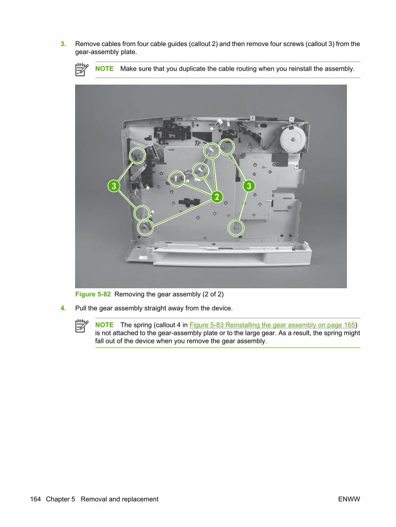
3. Remove cables from four cable guides (callout 2) and then remove four screws (callout 3) from thegear-assembly plate.
NOTE Make sure that you duplicate the cable routing when you reinstall the assembly.
233
Figure 5-82 Removing the gear assembly (2 of 2)
4. Pull the gear assembly straight away from the device.
NOTE The spring (callout 4 in Figure 5-83 Reinstalling the gear assembly on page 165)is not attached to the gear-assembly plate or to the large gear. As a result, the spring mightfall out of the device when you remove the gear assembly.
164 Chapter 5 Removal and replacement ENWW

Reinstallation notes for the gear assemblyReinstallation tip Close the cartridge door and press the large gear against the device chassisbefore you start to reinstall the gear assembly.
Reinstallation tip The spring (callout 4) has a locating pin that must be inserted into the smallhole in the gear-assembly plate before reinstallation.
Reinstallation tip Use the rod (callout 5) on the gear-assembly plate as a locator to find thecorrect position for the gear assembly. Insert the rod into the hole in the lower gear on the devicechassis.
Reinstallation tip Be careful not to catch any cables behind the gear-assembly plate whenreinstalling the screws.
5
4
Figure 5-83 Reinstalling the gear assembly
ENWW Reinstallation notes for the gear assembly 165
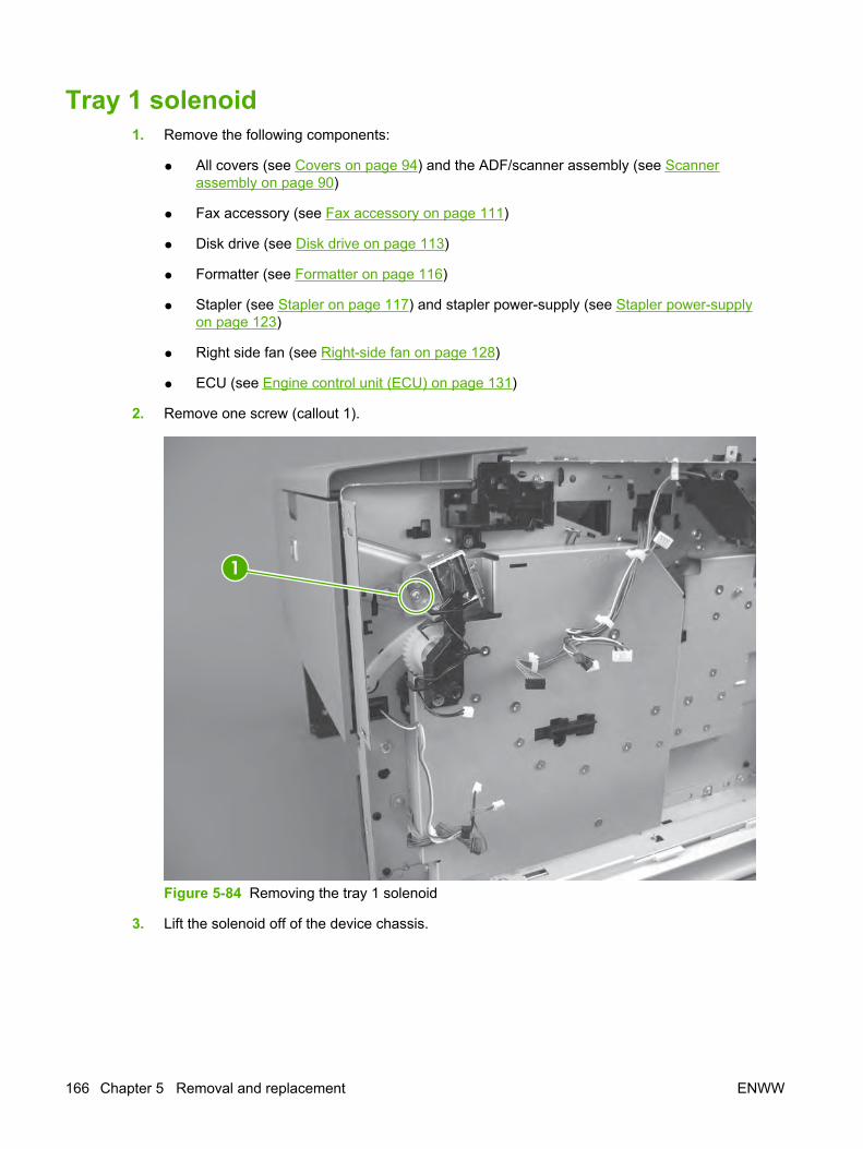
Tray 1 solenoid1. Remove the following components:
● All covers (see Covers on page 94) and the ADF/scanner assembly (see Scannerassembly on page 90)
● Fax accessory (see Fax accessory on page 111)
● Disk drive (see Disk drive on page 113)
● Formatter (see Formatter on page 116)
● Stapler (see Stapler on page 117) and stapler power-supply (see Stapler power-supplyon page 123)
● Right side fan (see Right-side fan on page 128)
● ECU (see Engine control unit (ECU) on page 131)
2. Remove one screw (callout 1).
1
Figure 5-84 Removing the tray 1 solenoid
3. Lift the solenoid off of the device chassis.
166 Chapter 5 Removal and replacement ENWW
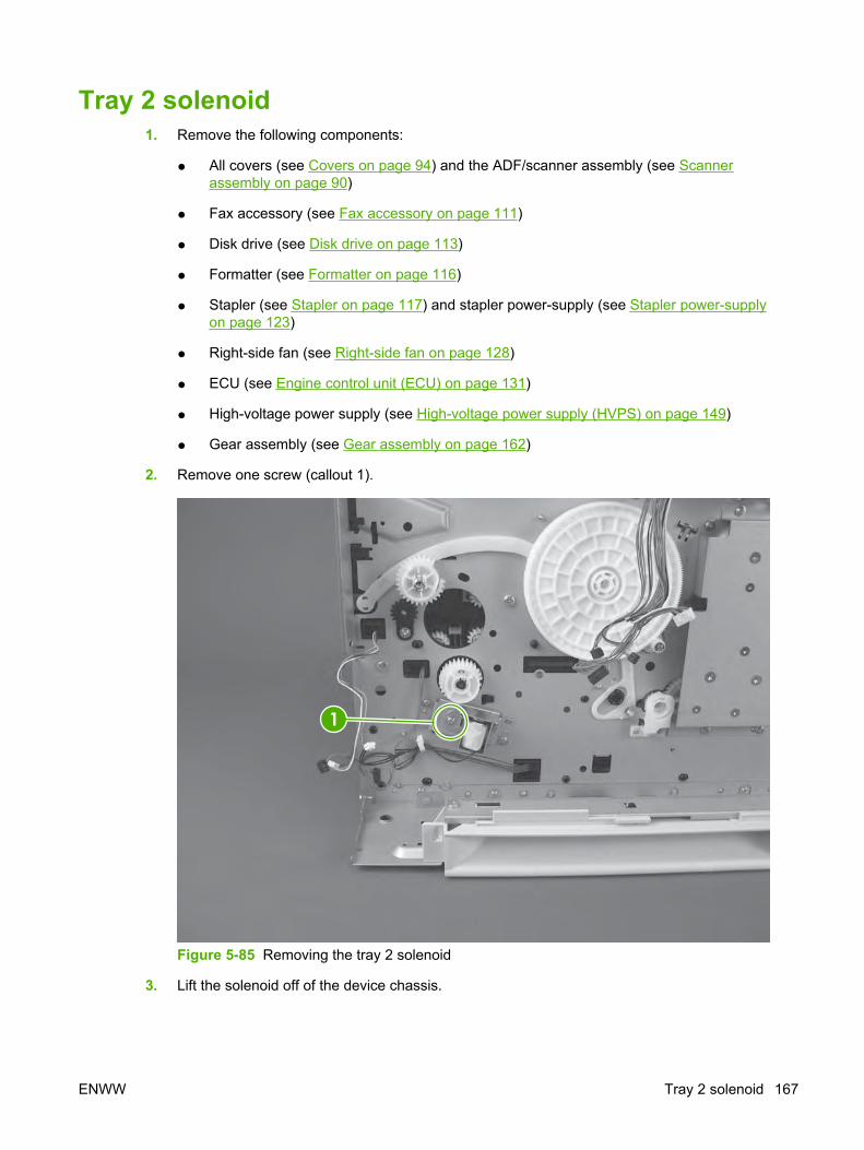
Tray 2 solenoid1. Remove the following components:
● All covers (see Covers on page 94) and the ADF/scanner assembly (see Scannerassembly on page 90)
● Fax accessory (see Fax accessory on page 111)
● Disk drive (see Disk drive on page 113)
● Formatter (see Formatter on page 116)
● Stapler (see Stapler on page 117) and stapler power-supply (see Stapler power-supplyon page 123)
● Right-side fan (see Right-side fan on page 128)
● ECU (see Engine control unit (ECU) on page 131)
● High-voltage power supply (see High-voltage power supply (HVPS) on page 149)
● Gear assembly (see Gear assembly on page 162)
2. Remove one screw (callout 1).
1
Figure 5-85 Removing the tray 2 solenoid
3. Lift the solenoid off of the device chassis.
ENWW Tray 2 solenoid 167

Pickup assembly1. Remove the following components:
● All of the covers (see Covers on page 94) and the ADF/scanner assembly (see Scannerassembly on page 90)
● Disk drive (see Disk drive on page 113)
● Formatter (see Formatter on page 116)
● Stapler (see Stapler on page 117) and stapler power-supply (see Stapler power-supplyon page 123)
● ECU (see Engine control unit (ECU) on page 131)
● Left-side riser (see Left-side riser on page 138)
● Access plate (see Access plate on page 144)
● Fuser (see Fuser on page 139)
● Oblique-roller assembly (see Oblique-roller assembly on page 146).
● Left-side fan (see Left-side fan on page 148)
Tip You do not have to unroute the left-side-fan cable in order to remove the HVPS,the feed-guide assembly, the gear assembly, or the pickup assembly. After removingthe fan from its hole in the chassis, simply set the fan down on the workspace.
● High-voltage power supply (see High-voltage power supply (HVPS) on page 149)
● Feed-guide assembly (see Feed-guide assembly on page 156)
● Gear assembly (see Gear assembly on page 162)
168 Chapter 5 Removal and replacement ENWW

2. Remove the cables from the cable guide (callout 1) and then remove two screws (callout 2) fromthe tray 2 solenoid plate. Press the tab on the pickup shaft gear (callout 3) and then slide the gearoff of the shaft.
NOTE Keep the parts of the pickup-shaft gear together to make sure that the small springinside remains with the gear.
1
2
3
Figure 5-86 Removing the pickup assembly (1 of 4)
ENWW Pickup assembly 169

3. Remove three screws (callout 4) from two tray guides at the right side of the device and then liftthe guides out of the device. Repeat the procedure to remove the tray guides at the left side of thedevice.
4
Figure 5-87 Removing the pickup assembly (2 of 4)
4. Tip the device so that it rests on its top.
170 Chapter 5 Removal and replacement ENWW

5. Press in the green tab (callout 5), remove two screws (callout 6) from the roller-stay assembly, andthen lift the assembly out of the device.
65
Figure 5-88 Removing the pickup assembly (3 of 4)
NOTE After removing the roller-stay assembly, the media-present sensor for tray 1 isexposed. To remove the sensor, remove one screw, unthread the sensor cable, and lift thesensor out of the device.
ENWW Pickup assembly 171

6. Use a short screwdriver to remove two screws (callout 7) and then remove the remaining twoscrews (callout 8) from the pickup assembly.
8
7
Figure 5-89 Removing the pickup assembly (4 of 4)
7. Lift the assembly out of the device starting at the opposite end from the gear-end of the assembly.
NOTE After removing the pickup assembly, the top-of-page sensor is easily accessible.To remove the top-of-page sensor, use a short screwdriver to remove two screws from thesensor cover, remove one screw from the sensor, unthread the sensor cable, and then liftthe sensor out of the device.
172 Chapter 5 Removal and replacement ENWW

Tray 1 media-present sensor and top-of-page sensorThe tray 1 media-present sensor is exposed when the roller-stay assembly is removed in step 5 of thepickup assembly removal (see Pickup assembly on page 168). To remove the sensor, remove one screw(callout 1), unthread the sensor cable, and then lift the sensor out of the device.
To remove the top-of-page sensor, remove the pickup assembly (see Pickup assembly on page 168and then remove two screws (callout 2) from the sensor cover. Lift the sensor cover out of the deviceto expose the top-of-page sensor, and then remove one screw from the sensor.
2
1
Figure 5-90 Removing the tray 1 media-present sensor and the top-of-page sensor
ENWW Tray 1 media-present sensor and top-of-page sensor 173

3
4
5
Figure 5-91 Media-width, top-of-page, and tray 1 media-present sensors
NOTE Figure 5-91 Media-width, top-of-page, and tray 1 media-present sensors on page 174shows three sensors:
Media-width sensor (callout 3), which can be removed after removing the high-voltage power-supply (see High-voltage power supply (HVPS) on page 149)
Top-of-page sensor (callout 4), which can be removed according to instructions in this section
Tray 1 media-present sensor (callout 5), which can be removed according to instructions in thissection
174 Chapter 5 Removal and replacement ENWW

E-label reader (memory tag)1. Remove all of the covers (see Covers on page 94) and the ADF/scanner assembly (see Scanner
assembly on page 90).
2. Disconnect one cable (callout 1), and then thread the cable through the hole in the device chassis.
Figure 5-92 Removing the e-label reader (1 of 2)
ENWW E-label reader (memory tag) 175

3. Remove one screw (callout 2).
Figure 5-93 Removing the e-label reader (2 of 2)
4. Lift the e-label reader out of the device.
Reinstallation tip Insert the tab at the front of the reader into the metal slot first.
176 Chapter 5 Removal and replacement ENWW

Face-down-roller shaft1. Remove all of the covers (see Covers on page 94) and the ADF/scanner assembly (see Scanner
assembly on page 90).
2. Rotate the bushings (callout 1) at both ends of the face-down-roller shaft .
NOTE The bushing on the left side of the device rotates to a horizontal position. Thebushing on the right side rotates approximately 45°.
Figure 5-94 Removing the face-down-roller shaft (1 of 2)
ENWW Face-down-roller shaft 177

3. Lift the end at the right side of the device, and then slide the shaft toward the right side to clear thehole on the left side of the device chassis.
Figure 5-95 Removing the face-down-roller shaft (2 of 2)
178 Chapter 5 Removal and replacement ENWW

Cartridge door1. Remove the left-side cover (see Left-side cover on page 97).
2. With the cartridge door closed, unhook the spring (callout 1) at the device chassis, and then removeone screw (callout 2).
Figure 5-96 Removing the cartridge door (1 of 3)
ENWW Cartridge door 179
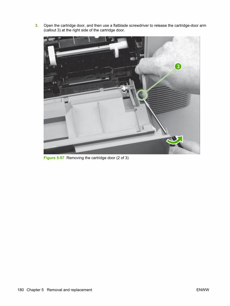
3. Open the cartridge door, and then use a flatblade screwdriver to release the cartridge-door arm(callout 3) at the right side of the cartridge door.
3
Figure 5-97 Removing the cartridge door (2 of 3)
180 Chapter 5 Removal and replacement ENWW

4. Slide the cartridge door to the left, off of the hinges, and then pull the door away from the device.
Figure 5-98 Removing the cartridge door (3 of 3)
ENWW Cartridge door 181

Transfer roller1. Open the cartridge door.
2. Release the left end of the transfer roller by using needle-nose pliers or a small flatblade screwdriverto pinch two tabs at the left end of the transfer roller.
Figure 5-99 Removing the transfer roller
3. Use the needle-nose pliers or flatblade screwdriver in the same manner to release the other end.
4. Lift the transfer roller out of the device.
NOTE The left end of the transfer roller has a spring attached. At the right end of the roller, thespring is attached to the device rather than to the roller. As a result, the spring at the right endremains in the device. Also, the gear assembly at the right end of the roller is not captive on theroller.
CAUTION Be careful not to touch the surface of the new transfer roller.
Reinstallation tip Align the springs with the tabs on the bottom of the roller-mounts beforepressing the roller into place.
182 Chapter 5 Removal and replacement ENWW

Registration assembly1. Remove the following components:
● Right-side cover (see Right-side cover on page 94)
● Formatter shield (see Formatter shield on page 95)
● Fax cover (see Fax cover on page 96)
● Left-side cover (see Left-side cover on page 97)
● ADF/scanner assembly (see Scanner assembly on page 90)
2. Unhook the clasp on the registration assembly gear (callout 1), and then slide the gear off of theshaft.
1
Figure 5-100 Removing the registration assembly (1 of 3)
ENWW Registration assembly 183

3. Remove two screws (callout 2) from the registration-assembly cover, and then lift the cover out ofthe device.
Figure 5-101 Removing the registration assembly (2 of 3)
184 Chapter 5 Removal and replacement ENWW

4. Remove four screws (callout 3).
Figure 5-102 Removing the registration assembly (3 of 3)
5. Lift the registration assembly out of the device, gear-end first.
ENWW Registration assembly 185

Tray 1 pickup roller1. Spread the pickup-roller locks (callout 1) on each side of the tray 1 pickup roller to release the roller.
Figure 5-103 Removing the tray 1 pickup roller
2. Rotate the top of the roller off of the shaft, and then lift the roller out of the device.
186 Chapter 5 Removal and replacement ENWW

Tray 2 pickup rollerNOTE Also follow these instructions to remove any optional-tray pickup rollers.
1. Tip the device over on its rear side, with the top of the device facing you.
2. Rotate the bushings (callout 1) on each side of the roller upward.
Figure 5-104 Removing the tray 2 pickup roller (1 of 2)
3. Remove the left-side bushing by sliding the bushing to the left.
4. Slide the roller and shaft toward the left until they clear the hole in the right-side bushing, and thenlift the right end of the shaft.
ENWW Tray 2 pickup roller 187

5. Slide the roller and shaft toward the right, and then lift the roller and shaft together out of the device.
Figure 5-105 Removing the tray 2 pickup roller (2 of 2)
188 Chapter 5 Removal and replacement ENWW
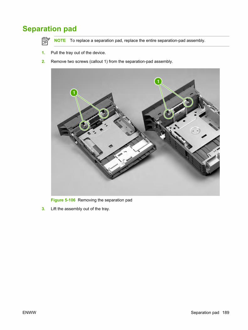
Separation padNOTE To replace a separation pad, replace the entire separation-pad assembly.
1. Pull the tray out of the device.
2. Remove two screws (callout 1) from the separation-pad assembly.
Figure 5-106 Removing the separation pad
3. Lift the assembly out of the tray.
ENWW Separation pad 189

190 Chapter 5 Removal and replacement ENWW

6 Troubleshooting
Chapter contents● Troubleshooting process
● Control-panel messages
● Clear jams
● Interface troubleshooting
● Service mode functions
● Troubleshooting tools
● Firmware updates and recovery
● Troubleshoot general printing problems
● Troubleshoot media-handling problems
● Troubleshoot print-quality problems
● Diagrams
ENWW Chapter contents 191

Troubleshooting processTroubleshooting tree
Figure 6-1 Basic troubleshooting
192 Chapter 6 Troubleshooting ENWW

Troubleshooting flowchartIf the device is not responding correctly, use the flowchart to determine the problem. If the device doesnot pass a step, follow the corresponding troubleshooting suggestions.
1. Does the control-panel display show READY?
YES Go to step 2.
NO
The control-paneldisplay is blank, andthe device fan is off.
● Turn the device off, and then turn it on again.
● Check the power cord connections and the power switch.
● Plug the device into a different outlet.
● Check that the power supplied to the device is steady, and meets device specifications. (SeeElectrical specifications on page 328.)
The control-paneldisplay appears withno backlighting.
Check the power connector to the ADF/scanner assembly.
The control-paneldisplay is blank, butthe device fan is on.
● Press a control-panel button to see if the device responds.
● Check the ribbon cable to the ADF/scanner assembly.
● Turn the device off, and then turn it on again.
The control-paneldisplay is in thewrong language.
● Turn the device off, and then turn it on again. When XXX MB appears on the control-paneldisplay, press and hold down the 6 key until all three lights remain illuminated. This could takeup to 10 seconds. Then, release the 6 key. Use the 3 and 9 keys to scroll to Language and thenpress the 6 key to select it. Use the 3 and 9 keys to scroll through the available languages to thelanguage you want and then press the 6 key to select it.
The control-paneldisplay showsgarbled or unfamiliarcharacters.
● Make sure that the appropriate language is selected at the device control panel.
● Turn the device off, and then turn the device on again.
A message otherthan READY appearson the control-paneldisplay.
● See Control-panel messages on page 201.
ENWW Troubleshooting process 193

2. Can you print a configuration page? (See Use information pages on page 45.)
YES Go to step 3.
NO
A configuration pagedoes not print.
● Verify that all trays are correctly loaded, adjusted, and installed in the device.
● At the computer, check the print queue or print spooler to see if the device has been paused. Ifproblems exist with the current print job, or if the device is paused, a configuration page will notprint. Press Stop and try again to print a configuration page.
A blank page prints. ● Verify that the sealing tape was removed from print cartridge. (See the getting started guide orthe instructions that came with the print cartridge.)
● The print cartridge might be empty. Install a new print cartridge.
A message otherthan READY orPRINTINGCONFIGURATIONappears on thecontrol-panel display.
● See Control-panel messages on page 201.
194 Chapter 6 Troubleshooting ENWW

3. Does the device copy?
YES Go to step 4.
NO
Poor copy qualityfrom the ADF.
1. If the print quality from the internal tests and the copy from the flatbed were acceptable, cleanthe ADF scanning strip. See Clean the scanner glass on page 43.
2. If the ADF is damaged, replace the ADF (see ADF assembly on page 80).
Media does not movesmoothly through theADF path.
1. Make sure that the media HP specifications. See Media specifications on page 15.
2. Clean the ADF roller and separation pad. See Clean the ADF on page 40 .
3. If the problem persists, replace the ADF roller.
4. If the problem persists, replace the ADF (see ADF assembly on page 80).
Poor copy qualityfrom the flatbed.
1. If the print quality from the internal tests and the copy from the ADF were acceptable, clean theflatbed glass. See Clean the scanner glass on page 43.
2. If, after performing the maintenance, the problem persists, see the user guide.
3. If the problem persists, replace the scanner assembly (see Scanner assembly on page 90).
ENWW Troubleshooting process 195

4. Does the device send a fax?
YES Go to step 5.
NO
The telephone line isnot operational or thedevice is not pluggedinto the telephoneline.
Verify that the device is plugged into a telephone line that operates correctly.
The telephone cord isfaulty or is pluggedinto the wrongconnector.
1. Verify that the device is connected to an analog fax line.
2. Try plugging the telephone cord into the other connector.
3. Try a new telephone cord.
The fax number isincorrect orincomplete.
Check the fax number and re-enter the correct and complete fax number.
Sent fax isincomplete or of poorquality.
See the user guide.
The device faxsettings are setincorrectly.
Review the device fax settings. See the HP LaserJet Analog Fax Accessory 300 User Guide.
If the error persists, replace the fax accessory (see Fax accessory on page 111).
196 Chapter 6 Troubleshooting ENWW

5. Does the device receive a fax?
YES Go to step 6.
NO
Too many telephonedevices are pluggedin, or telephonedevices are notconnected in thecorrect order.
Make sure that the device is the only device on the telephone line and try again to receive the fax.
The telephone corddoes not meetspecifications.
Verify that the device is connected to an analog fax line.
The device faxsettings are setincorrectly.
Review the device fax settings. See the user guide.
If the error persists, replace the fax accessory (see Fax accessory on page 111).
ENWW Troubleshooting process 197

6. Can you print from a program?
YES Go to step 7.
NO
The job will not print. ● If the job will not print, and a message appears on the control-panel display, see Control-panelmessages on page 201.
● By using the computer, check to see if the device has been paused. Press Stop to continue.
● If the device is on a network, print a configuration page. (See Use information pageson page 45.) If an HP Jetdirect print server is installed, a Jetdirect page also prints. Check theJetdirect configuration page to verify that the network protocol status and settings are correct forthe device.
● If the device is on a network, check that you are printing to the correct device. To verify that nonetwork problem exists, connect the computer directly to the device
● Check the interface cable connections. Disconnect and reconnect the cable at the computer andthe device.
● Test the cable by trying it on another computer.
● Make sure that the print job is being sent to the correct port (LPT1 or network printer port, forexample).
● Make sure that you are using the correct printer driver. (See the user guide.)
● Reinstall the printer driver. (See the getting started guide.)
● Check that the computer port is configured and working correctly. (Try connecting another deviceto that port and printing.)
● If you are using the PS driver to print, set Print PS Errors (on the General Print Behaviorsubmenu of the Device Behavior menu), to On and then try again to print the job.
● Make sure that Personality (on the General Print Behavior submenu of the DeviceBehavior menu) is set to Auto.
● You might be missing a device message that could help you solve the problem. On the Warning/Error Behavior submenu (of the Device Behavior menu) at the device control panel,temporarily turn off the Clearable Warnings and Auto-Continuable Events settings. Then tryagain to print the job.
A PS error page or listof commands prints.
● The device might have received a nonstandard PS code. For this print job, set thePersonality (on the General Print Behavior submenu of the Device Behavior menu) to PS.After the job has printed, return the setting to Auto.
● Make sure that the print job is a PS job, and that you are using the PS driver.
● The device might have received PS code although it is set to PCL. Set Personality (on theGeneral Print Behavior submenu of the Device Behavior menu) to Auto.
198 Chapter 6 Troubleshooting ENWW

7. Does the job print as expected?
YES Go to step 8.
NO
Print is garbled, oronly a portion of thepage prints.
● Make sure that you are using the correct printer driver. (See the user guide.)
● The data file that was sent to the device might be corrupt. To check, try printing the file to anotherdevice (if possible), or try a different file.
● Check the interface cable connections. Test the cable by trying it on another computer (ifpossible).
● Replace the interface cable with a high-quality cable (see Parts and diagrams on page 269).
● Simplify the print job, print at a lower resolution, or install more device memory.
● You might be missing a device message that could help you solve the problem. On the Warning/Error Behavior submenu (of the Device Behavior menu) at the device control panel,temporarily turn off the Clearable Warnings and Auto-Continuable Events settings. Then,print the job again.
Printing stops in themiddle of the job.
● Stop might have been pressed.
● Check that the power supplied to the device is steady, and that it meets device specifications.(See Electrical specifications on page 328.)
Print speed is slowerthan expected.
● Simplify the print job.
● Add more memory to the device.
● Turn banner pages off. (See the network administrator.)
● Note that slower speeds should be expected if you are printing narrow paper, printing from tray 1,using the HIGH 2 fuser mode, or if you have set Small Paper Speed to SLOW.
A control-panelsetting is not takingeffect.
● Check settings in the printer driver or program. (The printer driver and program settings overridecontrol-panel settings.)
The print job is notformatted correctly.
● Check that you are using the correct printer driver. (See the user guide.)
● Check the program settings. (See the program online Help.)
● Try a different font.
● Downloaded resources might have been lost. You might need to download them again.
Media does not feedcorrectly or isdamaged.
● Make sure that the media is loaded correctly and that the guides are not too tight or too looseagainst the stack of media.
● If you are having problems printing custom-size paper, see the user guide.
● If pages are wrinkled or curled, or if the image is skewed on the page, see Troubleshoot print-quality problems on page 248.
Print-qualityproblems occur.
● Adjust the print resolution. (See the user guide.)
● Check that Resolution Enhancement Technology (REt) is on. (See the user guide.)
● Go to Troubleshoot print-quality problems on page 248.
ENWW Troubleshooting process 199

8. Does the device select the correct trays?
YES For other problems, check the table of contents or the index in this manual, or see the printer-driver online Help.
NO
The device pullsmedia from the wrongtray.
● Make sure that you have selected the correct tray. (See the user guide.)
● Make sure that trays are correctly configured for size and type. (See the user guide.) Print aconfiguration page to see current tray settings. (See Use information pages on page 45.)
● Make sure that the tray selection (Source) or Type in the printer driver or program is set correctly.(The printer driver and program settings override the device control-panel settings.)
● By default, media loaded in tray 1 will be printed first. If you do not want to print from tray 1,remove any media loaded in the tray or change the USE REQUESTED TRAY setting. (See theuser guide.) Change TRAY 1 SIZE and TRAY 1 TYPE to a setting other than ANY.
An optional tray is notworking correctly.
● Print a configuration page to verify that the tray is installed correctly and is functional. (See Useinformation pages on page 45.)
● Configure the printer driver to recognize the installed tray. (See the printer driver online Help.)
● Turn the device off, and then turn it on again.
● Verify that you are using the correct optional tray for the device.
A message other thanREADY appears onthe control-paneldisplay.
● See Control-panel messages on page 201.
200 Chapter 6 Troubleshooting ENWW

Control-panel messagesControl-panel message types
Four types of control-panel messages can indicate the status of or problems with the device.
Message type Description
Status messages Status messages reflect the current state of the device. They inform you of normal device operationand require no interaction to clear them. They change as the state of the device changes. Wheneverthe device is ready, not busy, and has no pending warning messages, the status message Readyappears if the device is online.
Warning messages Warning messages inform you of data and print errors. These messages typically alternate withthe Ready or status messages and remain until you touch OK. Some warning messages are clearable.If Clearable Warnings is set to Job on the device Device Behavior menu, the next print job clearsthese messages.
Error messages Error messages communicate that some action must be performed, such as adding paper or clearinga jam.
Some error messages are auto-continuable. If Auto Continue is set on the menus, the device willcontinue normal operation after an auto-continuable error message appears for 10 seconds.
NOTE Pressing any button during the 10-second auto-continuable error message overridesthe auto-continue feature, and the button function takes precedence. For example, pressingthe Stop button pauses printing and offers the option to cancel the print job.
Critical-error messages Critical error messages inform you of a device failure. Some of these messages can be cleared byturning the device off and then on. These messages are not affected by the Auto Continue setting.If a critical error persists, service is required.
Resolve control-panel messagesTable 6-1 Control-panel messages
Control panel message Description Recommended action
Digital Send Server is not Responding.Contact Administrator.
The device cannot communicate with theDigital Send Server.
Contact the network administrator.
10.10.00 ERROR The device cannot read or write to the printcartridge e-label, or the e-label is missingfrom the print cartridge.
1. Verify that a genuine HP print cartridgeis installed in the device.
2. Verify that the memory tag PCA isinstalled in the device.
3. Verify that the memory tag connector isfirmly seated in connector J510 on theECU. You might have to remove themain cooling fan to see this connection.
10.32.00 - Unauthorized Supply A supply has been installed that does notpass the authentication test for genuine HPsupplies.
If you believe you purchased a genuine HPsupply, visit us at www.hp.com/go/anticounterfeit. Any repair required as a resultof using non-HP supplies or unauthorizedsupplies is not covered under warranty. HPcannot ensure the accuracy or the availabilityof certain features.
To continue printing, touch OK.
ENWW Control-panel messages 201

Control panel message Description Recommended action
11.XX - Internal clock error To continuetouch OK
The device real time clock has experiencedan error.
Whenever the device is turned off and thenturned on again, set the time and date at thecontrol panel. See the Time/Schedulingmenu in the user guide.
If the error persists, you might need to replacethe formatter.
13.00.02 - Jam in Tray 1 Clear jam thentouch OK
Paper is fed from tray 2 to the device by thetray 2 pick-up roller. When energized,solenoid SL2 releases a clutch, and then thepick-up roller rotates to pick up the paper andadvance it into the paper path.
1. Follow the instructions in the onscreendialog box, or see Clear jams from theinput-tray areas on page 220.
2. Verify that the type and quality of themedia that you are using meetHP specifications. (See Mediaspecifications on page 15.)
3. Verify that the media is loaded correctlyand that the guides are not too tight ortoo loose against the stack of media.
4. Verify that the tray 2 pickup roller andseparation pad are installed correctly.
5. Verify that solenoid SL2 is beingenergized. If you cannot hear it during aprint job, remove tray 2, override thepaper presence sensor flag, start a printjob, and then see if the pick-up roller isrotating.
6. Verify that solenoid SL2 is firmly seatedin connector J504 on the ECU.
13.01.00 - Jam in Tray 1 Clear jam thentouch OK
The paper did not reach the top of pagesensor within the specified period of time. Thetray 1 feed roller moves paper into the paperpath. When solenoid SL1 is energized, aclutch mechanism allows the paper stack intray 1 to lift, and then allows the feed roller torotate one time to move the paper into thepaper path.
1. Follow the instructions in the onscreendialog box, or see Clear jams from theinput-tray areas on page 220.
2. Verify that the type and quality of themedia that you are using meetHP specifications. (See Mediaspecifications on page 15.)
3. Verify that the media is loaded correctlyand that the guides are not too tight ortoo loose against the stack of media.
4. Verify that the tray 1 pickup roller andseparation pad are installed correctly.
5. Verify that solenoid SL1 is firmly seatedin ECU connector J508. Verify that SL1is being energized by removing thecover and observing the solenoid duringa feed operation.
6. Open and close the cartridge door toclear the error message.
Table 6-1 Control-panel messages (continued)
202 Chapter 6 Troubleshooting ENWW

Control panel message Description Recommended action
13.05.00 Jam inside front door Paper failed to reach the delivery sensorwithin a specified period of time when a printjob was initiated. When troubleshootingpaper jams, always observe where theleading edge of the paper stops in the jam.
1. Follow the instructions in the onscreendialog box, or see Clear jams from theinput-tray areas on page 220.
2. Verify that nothing is obstructing papermovement within the paper path.
3. Verify that the fuser motor (M2)connector is firmly seated. The fusermotor wiring is hard-wired to the back ofthe ECU at connector J501. The motorconnector is free-standing behind theECU. To see if the fuser motor isfunctional, observe the output stackerrollers while turning on the device. If therollers rotate, the motor is functional. Ifthey do not rotate, verify the connection.
13.15.00 - Jam inside front door Removeprint cartridge
Media is jammed in the fuser area. Follow the instructions in the onscreen dialogbox, or see Clear jams from the print-cartridge area on page 219.
If the message persists, check the thermistordelivery sensor (J405) and delivery sensor(SR2) cable connections.
13.20 - Jam inside rear bin Clear jam thenopen and close front door
Media is jammed in the output bin. Open the rear output bin and gently removethe jammed media. Follow the instructions inthe onscreen dialog box, or see Clear jamsfrom the output-bin areas on page 223.
13.31.00 Jam inside front door Media is jammed in the paper path. Follow the instructions in the onscreen dialogbox, or see Clear jams from the input-trayareas on page 220.
If the message persists, check the rear door(face-up bin) sensor cable connection.
13.65 - Jam inside rear bin Clear jam thenopen and close front door
Media is jammed in the fuser area. Open the rear output bin and gently removethe jammed media. Follow the instructions inthe onscreen dialog box, or see Clear jamsfrom the output-bin areas on page 223.
If the message persists, check the thermistordelivery sensor (J405) and delivery sensor(SR2) cable connections.
13.67.00 - Jam inside front door Media is jammed in the paper path. Follow the instructions in the onscreen dialogbox, or see Clear jams from the print-cartridge area on page 219.
If the message persists, check the HVPSribbon-cable connection at J404.
13.XX.YY - Paper wrapped around fuser A jam has occurred because paper haswrapped around the fuser.
Follow the instructions in the onscreen dialogbox.
13.XX.YY - Remove Tray 2 Clear jam thentouch OK
Media is jammed in the duplex area. Follow the instructions in the onscreen dialogbox, or see Clear jams from the input-trayareas on page 220.
20 Insufficient memory To continue touchOK
The device received more data than can fit inthe available memory. You might have tried
Touch OK to print the transferred data (somedata might be lost), and then simplify the printjob or install additional memory.
Table 6-1 Control-panel messages (continued)
ENWW Control-panel messages 203

Control panel message Description Recommended action
to transfer too many macros, soft fonts, orcomplex graphics.
21 Page too complex To continue touchOK
The page formatting process was not fastenough for the device.
Touch OK to print the transferred data. (Somedata might be lost.) If this message appearsoften, simplify the print job.
22 EIO <X> buffer overflow To continuetouch OK
Too much data was sent to the EIO card inthe specified slot (X). An incorrectcommunications protocol might be in use.
Touch OK to print the transferred data. (Somedata might be lost.)
Check the host configuration. If this messagepersists, you might have to replace the EIOcard.
22 Embedded I/O buffer overflow Tocontinue touch OK
Too much data was sent to the embeddedHP Jetdirect print server.
Touch OK to print the transferred data. (Somedata might be lost.)
22 USB I/O buffer overflow To continuetouch OK
Too much data was sent to the USB buffer. Touch OK to clear the error message. (Datawill be lost.)
30.1.YY Scanner failure An error has occurred in the scanner. 1. Make sure that the scanner lock is in theunlocked position.
2. Turn the device off and then on.
3. Check the cable connections betweenthe ADF/scanner assembly and theformatter.
4. If this message persists, replace thescanner assembly (see Scannerassembly on page 90).
5. If, after replacing the scanner assembly,the message persists, replace theformatter (see Formatter on page 116).
40 EIO <X> bad transmission To continuetouch OK
The connection between the device and theEIO card in the specified slot has beenbroken.
Touch OK to clear the error message andcontinue printing. Check the EIO connection.
40 Embedded I/O bad transmission Tocontinue touch OK
A temporary printing error has occurred. 1. Turn the device off, and then turn thedevice on.
2. If this message persists, replace theformatter (see Formatter on page 116).
41.3 - Load tray <XX> To use another tray,touch OK
The specified tray does not contain thespecified media size.
Touch OK to use a tray that contains mediaof the correct size.
41.3 - Load tray <XX>: <Type>, <Size> The specified tray is loaded with media thatis longer or shorter in the feed direction thanthe size configured for the tray.
Touch OK to display Tray <X> Size.Reconfigure the size in a tray so that thedevice will use a tray that is loaded with thesize of media required for the print job. If themessage does not clear automatically fromthe control-panel display, turn the device off,and then turn the device on.
41.X Error To continue touch OK A temporary printing error occurred.
X description
2 beam detect misprint
8 fuser too hot
1. Touch OK to clear the error. If the erroris not cleared, turn the device off, andthen turn the device on.
2. If the message persists, replace thefuser (see Fuser on page 139).
Table 6-1 Control-panel messages (continued)
204 Chapter 6 Troubleshooting ENWW

Control panel message Description Recommended action
49.XXXXX ERROR To continue turn offthen on
A critical firmware error has occurred. 1. Turn the device off, and then turn thedevice on.
2. Go to www.hp.com/support/LJM3027mfp or www.hp.com/support/LJM3035mfp to check the latestfirmware image version. If the latestfirmware image version is newer thanthe one installed on the device, upgradethe device.
3. Try printing a job from a differentsoftware program. If the job prints, goback to the first program and try printinga different file. If the message appearsonly with a certain software program orprint job, then the error is in the softwareprogram and not in the device. If the jobfails to print using a different softwareprogram, then turn off the device anddisconnect all cables that connect thedevice to the network or to a computer.
4. Remove any DIMMs and EIO cards, andthen turn the device on.
5. If, after removing DIMMs and EIO cards,the device behaves normally, turn offthe device and reinstall DIMMs and EIOcards one-by-one, turning off the deviceoff and then on again each time youreinstall a DIMM or EIO card. If a certainDIMM or EIO card causes the messageto reappear, replace the DIMM or EIOcard.
6. Reconnect all cables that connect thedevice to the network or to a computer.
7. If the message persists, replace theformatter (see Formatter on page 116).
50.1 FUSER ERROR AC power is not being provided to the fuserassembly. AC voltage is necessary togenerate heat in the fuser assembly.
1. Verify that the connection between thefuser assembly and the ECU is fullyseated.
2. If the message persists, replace thefuser assembly.
50.6 FUSER ERROR The main or sub thermistors are unable toprovide temperature feedback to the ECU.The main and sub thermistors monitor thefuser assembly hot-roller temperature andprovide feedback to regulate the fusingtemperature.
1. Verify that the seven-wire connector isfirmly seated in connector J405 on theECU. You might have to remove themain cooling fan to see this connection.
2. Verify that the four-wire connector isfirmly seated in the fuser assembly.
3. Verify that the AC voltage is beingprovided to the fuser assembly.
4. If the message persists, replace thefuser assembly.
Table 6-1 Control-panel messages (continued)
ENWW Control-panel messages 205

Control panel message Description Recommended action
50.X FUSER ERROR To continue turn offthen on
A fuser error has occurred.
X description
1 low fuser temperature
2 fuser warmup service
3 fuser over-temperature
4 faulty fuser
5 incorrect fuser is installed
6 open fuser circuit
1. Turn the device off, and then turn thedevice on.
2. If the message persists, turn off thedevice to allow the fuser to cool.
3. Verify that the correct model fuser isinstalled in the device.
4. Check the cable connections betweenthe ECU and the fuser.
5. If, after checking the cables, themessage persists, replace the fuser(see Fuser on page 139).
6. If, after replacing the fuser, the messagepersists, replace the ECU (see Enginecontrol unit (ECU) on page 131).
7. If, after replacing the ECU, the messagepersists, replace the high-voltagepower-supply (see High-voltage powersupply (HVPS) on page 149).
51.XY ERROR To continue turn off then on A temporary printing error has occurred. 1. Turn the device off, and then turn thedevice on.
2. Check the cable connections betweenthe laser/scanner and the ECU.
3. If, after checking the cables, themessage persists, replace the laser/scanner (see Laser/scanneron page 142).
4. If, after replacing the laser/scanner, themessage persists, replace the ECU(see Engine control unit (ECU)on page 131).
52.00 ERROR A laser/scanner motor error has occurred.Laser/scanner motor rotation is verified at theinitialization of a print job.
1. Verify that the laser/scanner motorconnector and the ribbon cable from theECU are firmly seated on the laser/scanner assembly.
2. Verify that the laser/scanner motorconnector is firmly seated in connectorJ402 on the ECU. You might have toremove the main cooling fan to see thisconnection.
3. Verify that the ribbon cable installed inconnector J403 on the ECU is fullyseated. You must remove the ECU inorder to verify this connection.
4. If, after checking the cables, themessage persists, replace the laser/scanner (see Laser/scanneron page 142).
5. If, after replacing the laser/scanner, themessage persists, replace the ECU
Table 6-1 Control-panel messages (continued)
206 Chapter 6 Troubleshooting ENWW

Control panel message Description Recommended action
(see Engine control unit (ECU)on page 131).
53.XY.ZZ CHECK RAM DIMM SLOT <X> Tocontinue turn off then on
A problem exists with the device memory.The DIMM that caused the error will not beused.
X description
0 onboard memory
1 slot 1
You might need to reinstall or replace thespecified DIMM.
1. Turn the device off, and then replace theDIMM that caused the error. See Installmemory on page 30.
2. If, after replacing the DIMM, themessage persists, replace the formatter(see Formatter on page 116).
54.XX ERROR To continue turn off then on A temporary printing error has occurred. 1. Turn the device off, and then turn thedevice on.
2. If the message persists, check thesensors in the device to make sure thatthey are working correctly.
3. If the sensors are working correctly, butthe message persists, replace the ECU(see Engine control unit (ECU)on page 131).
55.05 ERROR To continue turn off then on The print engine is not communicating withthe formatter.
An error occurred while performing a remotefirmware upgrade.
1. Turn the device off, and then turn thedevice on.
2. Try again to perform the remotefirmware upgrade.
55.XX.YY DC CONTROLLER ERROR Tocontinue turn off then on
The print engine is not communicating withthe formatter.
1. Turn the device off, and then turn thedevice on.
2. If the message persists, replace theECU (see Engine control unit (ECU)on page 131).
3. If, after replacing the ECU, the messagepersists, replace the high-voltagepower-supply (see High-voltage powersupply (HVPS) on page 149).
56.XX ERROR To continue turn off then on A temporary printing error has occurred. 1. Turn the device off, and then turn thedevice on.
2. If this message persists, uninstall andthen reinstall all input trays, and thenturn the device off.
3. Turn the device on. If the messagepersists, replace the formatter (seeFormatter on page 116).
57.03 ERROR To continue turn off then on A sub cooling fan (FM2) error has occurred.Fan operation is verified during device power-up. Fan operation occurs only during power-up or during a print job.
1. Turn the device off, and then turn thedevice on.
2. Verify that nothing is hindering orblocking the fan.
3. Verify that the fan is connected toconnector J512 on the ECU PCA. You
Table 6-1 Control-panel messages (continued)
ENWW Control-panel messages 207

Control panel message Description Recommended action
might have to remove the main coolingfan to see this connection.
4. If the message persists, replace the fan(see Left-side fan on page 148).
57.04 ERROR To continue turn off then on A main cooling fan (FM1) error has occurred.Fan operation is verified during device power-up. Fan operation occurs only during power-up or during a print job.
1. Turn the device off and then on.
2. Verify that nothing is hindering orblocking the fan.
3. Verify that the fan is connected toconnector J509 on the ECU PCA.
4. If the message persists, replace the fan(see Right-side fan on page 128).
59.50 ERROR To continue turn off then on A main motor (M1) error has occurred. Motoroperation is verified during device power-up.
1. Turn the device off, and then turn thedevice on.
2. Verify that nothing is hindering the mainmotor. If necessary, remove all papertrays and the print cartridge, and thenturn on the device and listen for motoroperation.
3. Verify that the main motor is connectedto connector J407 on the ECU. Youmight have to remove the main coolingfan to see this connection.
4. If the message persists, replace themotor (see Main motor on page 159).
62 NO SYSTEM To continue turn off thenon
A problem exists with the device firmware. 1. Turn the device off, and then turn thedevice on.
2. Go to www.hp.com/support/LJM3027mfp or www.hp.com/support/LJM3035mfp to check the latestfirmware image version. If the latestfirmware image version is newer thanthe one installed on the device, upgradethe device, if possible.
3. If the message persists, replace theformatter (see Formatter on page 116).
64 ERROR To continue turn off then on A scan buffer error occurred. 1. Turn the device off, and then turn thedevice on.
2. Go to www.hp.com/support/LJM3027mfp or www.hp.com/support/LJM3035mfp to check the latestfirmware image version. If the latestfirmware image version is newer thanthe one installed on the device, upgradethe device, if possible.
3. If the message persists, replace theformatter (see Formatter on page 116).
Table 6-1 Control-panel messages (continued)
208 Chapter 6 Troubleshooting ENWW

Control panel message Description Recommended action
68.X Permanent storage full To continuetouch OK
68.X Permanent storage write fail Tocontinue touch OK
The device NVRAM is full or the storagedevice is failing to write. Some settings savedin the NVRAM might have been reset to thefactory defaults. Printing can continue, butsome unexpected functions might occur if anerror occurred in permanent storage.
X description
0 onboard NVRAM
1 disk drive
Touch OK to clear the message. If themessage is not cleared, turn the device off,and then turn the device on.
68.0, onboard NVRAM
1. If the message persists, perform anNVRAM initialization (see Service modefunctions on page 226). Make sure thatyou read and understand the cautionand the note in that section.
2. If, after performing an NVRAM init, themessage persists, replace the formatter(see Formatter on page 116).
68.1, disk drive
1. Use the HP Web Jetadmin software todelete files from the disk drive.
2. If, after deleting files from the disk drive,the message persists, reinitialize thedisk drive (see Service mode functionson page 226). Make sure that you readand understand the caution and the notein that section.
3. If, after reinitializing the disk drive, themessage persists, replace the disk drive(see Disk drive on page 113).
68.X Storage error settings changed Tocontinue touch OK
One or more device settings in NVRAM areinvalid and have been reset to the factory-default settings. Printing can continue, butsome unexpected functions might occur if anerror occurred in permanent storage.
1. Touch OK to clear the message. If themessage is not cleared, turn the deviceoff, and then turn the device on.
2. Check the device settings to determinewhich settings have changed.
3. Perform an NVRAM initialization (seeService mode functions on page 226).Make sure that you read andunderstand the caution and the note inthat section.
4. If, after performing an NVRAMinitialization, the message persists,replace the formatter (see Formatteron page 116).
79.XXXX ERROR To continue turn off thenon
A critical hardware error occurred. 1. Turn the device off, and then turn thedevice on.
2. Go to www.hp.com/support/LJM3027mfp or www.hp.com/support/LJM3035mfp to check the latestfirmware image version. If the latestfirmware image version is newer thanthe one installed on the device, upgradethe device.
3. Try printing a job from a differentsoftware program. If the job prints, goback to the first program and try printing
Table 6-1 Control-panel messages (continued)
ENWW Control-panel messages 209

Control panel message Description Recommended action
a different file. If the message appearsonly with a certain software program orprint job, then the error is in the softwareprogram and not in the device. If the jobfails to print using a different softwareprogram, then turn off the device anddisconnect all cables that connect thedevice to the network or to a computer.
4. Remove any DIMMs and EIO cards, andthen turn the device on.
5. If, after removing DIMMs and EIO cards,the device behaves normally, turn offthe device and reinstall DIMMs and EIOcards one-by-one, turning off the deviceoff and then on again each time youreinstall a DIMM or EIO card. If a certainDIMM or EIO card causes the messageto reappear, replace the DIMM or EIOcard.
6. Reconnect all cables that connect thedevice to the network or to a computer.
7. If the message persists, replace theformatter (see Formatter on page 116).
8X.YYYY EIO ERROR To continue turn offthen on
The EIO accessory card has encountered acritical error, as specified by YYYY.
1. Turn the device off, and then turn thedevice on.
2. Turn the device off, reinstall the EIOaccessory, and then turn the device on.
3. Replace the EIO accessory.
8X.YYYY EMBEDDED JETDIRECT ERRORTo continue turn off then on
The embedded HP Jetdirect print server hasencountered a critical error, as specified byYYYY.
1. Turn the device off, and then turn thedevice on.
2. Go to www.hp.com/support/LJM3027mfp or www.hp.com/support/LJM3035mfp to check the latestfirmware image version. If the latestfirmware image version is newer thanthe one installed on the device, upgradethe device, if possible.
3. If the message persists, replace theformatter (see Formatter on page 116).
Action not currently available for Tray <X>Tray size cannot be any size/any custom
A duplexed (2-sided) document wasrequested from a tray that is set to Any sizeor Any custom. Duplexing is not allowedfrom a tray configured to Any size or Anycustom.
Select another tray or reconfigure the tray.
Authentication Required Authentication has been enabled for thisfeature or destination. A user name andpassword are required.
Type the user name and password, or contactthe network administrator.
Authentication Required To Use ThisFeature
A user name and password are required. Type the user name and password, or contactthe network administrator.
Table 6-1 Control-panel messages (continued)
210 Chapter 6 Troubleshooting ENWW

Control panel message Description Recommended action
Cannot duplex close rear bin The device cannot print on both sides of thepage if the rear output bin is open.
Close the rear output bin.
Check the glass and remove any paper Tocontinue press Start
A digital send or copy job has been performedfrom the scanner glass, but the originaldocument needs to be removed.
Remove the original document from thescanner glass, and then press Start.
Chosen personality not available Tocontinue touch OK
A print job requested a language (personality)that is not available for this device. The jobwill not print and will be cleared frommemory.
Print the job by using a printer driver for adifferent printer language, or add therequested language to the device (ifpossible). To see a list of availablepersonalities, print a configuration page.See Use information pages on page 45.
CLEANING DISK X% COMPLETE
alternates with
DO NOT POWER OFF
The memory disk is being cleaned. Thisprocess might take up to an hour. During thistime, no jobs can be printed.
Do not turn off the device. Wait for theprocess to complete.
The device automatically restarts at the endof the cleaning process.
Close front door The front door is open. Close the front door. If the message persists,make sure that the front-door microswitch isinstalled correctly and that it is operational.
Digital send communication error The device is unable to connect to the DigitalSending Software.
Make sure that the Digital Sending Softwareis running and that the Digital SendingSoftware and the device are on the network.
Document feeder cover open The document feeder (ADF) cover is open. Close the document feeder (ADF) cover.Follow the instructions in the onscreen dialogbox.
Document feeder empty The document feeder (ADF) does not containpaper.
Load paper in the document feeder (ADF)input tray.
Document feeder pick error The document feeder (ADF) experienced anerror while picking media.
Make sure that your original contains no morethan 50 pages. Follow the instructions in theonscreen dialog box.
If this message appears frequently, clean theADF roller assembly (see Clean the ADFon page 40). If, after cleaning the ADF rollerassembly, the message persists, replace theADF roller assembly.
E-mail Gateway did not accept the jobbecause the attachment was too large.
The scanned documents have exceeded thesize limit of the e-mail gateway.
Send the job again using a lower resolution,smaller file size setting, or fewer pages.See Use the embedded Web serveron page 49 to learn how to reduce the size ofthe attachment. Contact the networkadministrator to enable sending the scanneddocuments by using multiple e-mails.
E-mail Gateway did not respond. Jobfailed.
A gateway has exceeded the time out value. Validate the SMTP IP address. See the userguide.
E-mail Gateway rejected the job becauseof the addressing information. Job failed.
One or more of the e-mail addresses isincorrect.
Send the job again with the correctaddresses.
Error executing Digital Send job. Jobfailed.
A digital send job has failed and cannot bedelivered.
Try to send the job again.
HP digital sending: delivery error A digital send job has failed and cannot bedelivered.
Send the job again.
Table 6-1 Control-panel messages (continued)
ENWW Control-panel messages 211

Control panel message Description Recommended action
Initializing scanner The device is initializing the scanner. Wait for the control-panel display to showReady.
Install black cartridge The device detects the print cartridge bydetecting a voltage differential within thecartridge. The photo-conductive drumconnected to the high-voltage power supplyprovides the reference with which to measurethe differential.
1. Verify that a print cartridge is installed inthe device.
2. Verify that the drum ground connectoron the high-voltage power supply iscorrectly seated on the mechanicalconnector.
3. Verify that the cartridge mechanismfunctions correctly. When the cartridgeis removed from the device, themechanism swings outward, away fromthe chassis. When the cartridge isinserted into the device, the mechanismcloses toward the chassis.
Insufficient memory to load fonts/data<device> To continue touch OK
The device does not have enough memory toload the data (for example, fonts or macros)from the location specified.
Touch OK to continue without thisinformation. If the message persists, addmore memory.
Jam in document feeder Media is jammed in the document feeder(ADF).
Remove jammed media from the documentfeeder (ADF). Follow the instructions in theonscreen dialog box, or see Clear jams fromthe ADF on page 217.
If the message persists after all jams havebeen cleared, a sensor might be stuck orbroken. Check the sensors in the ADF. If asensor is broken, replace the ADF assembly(see ADF assembly on page 80).
Load Tray 1: <type>, <size> The tray is empty or configured for a differentsize than the size requested.
Follow the instructions in the onscreen dialogbox. If the message persists, make sure thatthe tray 1 media-present sensor (PS902) isoperational.
Manually feed: <type>, <size> The specified job requires manual feed fromtray 1.
Load the requested media into tray 1.
To override the message, touch OK to use atype and size of media that is available inanother tray.
Non HP supply installed Economodedisabled
A non-HP supply or a refilled HP supply hasbeen installed.
Follow the instructions in the onscreen dialogbox.
Order black cartridge The number of pages remaining for the printcartridge has reached the low threshold. Thedevice was set to stop printing when a supplyneeds to be ordered.
Touch OK to continue printing until the printcartridge is out of toner.
To order a new print cartridge, see Orderparts, accessories, and supplieson page 314.
Output bin <X> full The specified output bin is full, and printingcannot continue.
Empty the bin to continue printing.
Password or name is incorrect. Pleaseenter correct login.
The user name or password was typedincorrectly.
Retype the user name and password.
PIN is incorrect. Please re-enter PIN. The PIN was typed incorrectly. Retype the PIN.
Table 6-1 Control-panel messages (continued)
212 Chapter 6 Troubleshooting ENWW

Control panel message Description Recommended action
Please turn device off and install harddisk.
The requested job requires a hard disk, butthe device does not have a hard diskinstalled.
Turn the device off and install a hard disk.
Replace black cartridge The print cartridge is out of toner.
NOTE Depending on how thedevice is configured, this messagemight appear when it is time to ordera new print cartridge. In this case,the message indicates that you cantouch OK to continue printing.
Replace the print cartridge. (See Change theprint cartridge on page 27.)
Sanitizing disk <X>% complete Do notpower off
The hard disk is being cleaned. Contact the network administrator.
Scan failure Press Start to rescan The scan was unsuccessful and thedocument needs to be rescanned.
If necessary, reposition the document torescan it, and then press Start.
SMTP gateway not responding The SMTP gateway has exceeded a time outvalue.
Verify the e-mail server address. See the userguide. Contact the network administrator.
The digital sending service at <IPAddress> does not service this MFP.Contact administrator.
The device cannot communicate with thespecified IP address.
Verify the IP address. Contact the networkadministrator.
The digital sending service must beupgraded to support this version of theMFP firmware. Contact administrator.
The digital sending service is not supportedby the device firmware version that iscurrently installed.
Check the firmware version. Contact thenetwork administrator.
The folder you have entered is not a validfolder.
The folder name was entered incorrectly, orthe folder does not exist.
Re-enter the folder name correctly, or add thefolder.
Tray XX Open or Empty The tray indicated is either open or empty. Load or close the tray. Printing can continuefrom another tray.
Unable to connect A network connection is not detected. Verify the network connection. Contact thenetwork administrator.
Unable to copy The device was unable to copy the document.If this message persists, contact an HP-authorized service or support provider. (Seethe HP support flyer, or go to www.hp.com/support/LJM3027mfp or www.hp.com/support/LJM3035mfp.)
To temporarily hide this message in order tofax or send to e-mail, touch Hide.
Unable to send A network connection is not detected. Verify the network connection. Contact thenetwork administrator.
Unable to send fax. Please check faxconfiguration.
The device is unable to send a fax job. Contact the network administrator. Also seethe HP LaserJet Analog Fax Accessory 300User Guide for additional configuration andtroubleshooting information.
Unable to store job The device is unable to store a job. To temporarily hide this message in order tofax or send to e-mail, touch Hide. If thismessage persists, replace the disk drive(see Disk drive on page 113).
User name or password is incorrect.Please re-enter.
The user name or password was typedincorrectly.
Retype the user name and password.
User name, job name, or PIN is missing. One or more of the required items has notbeen selected or typed.
Select the correct user name and job name,and type the correct PIN.
Table 6-1 Control-panel messages (continued)
ENWW Control-panel messages 213

Clear jamsWhen clearing jams, be very careful not to tear the media. If a small piece of media remains in the device,it could cause additional jams.
Common causes of jamsThe device is jammed.1
Cause Solution
The media does not meet specifications. Use only media that meets HP specifications. See Mediaspecifications on page 15.
A component is installed incorrectly. Verify that the print cartridge is correctly installed.
You are using media that has already passed through a deviceor copier.
Do not use media that has been previously printed on orcopied.
An input tray is loaded incorrectly. Remove any excess media from the input tray. Make sure thatthe stack is below the maximum stack height mark in the tray.See Install trays on page 23.
The media is skewed. The input-tray guides are not adjusted correctly. Adjust themso they hold the stack firmly in place without bending it.
The media is binding or sticking together. Remove the media, flex it, rotate it 180°, or flip it over. Reloadthe media into the input tray.
The media is removed before it settles into the output bin. Reset the device. Wait until the page completely settles in theoutput bin before removing it.
During two-sided printing, you removed the paper before thesecond side of the document was printed.
Reset the device and print the document again. Wait until thepage completely settles in the output bin before removing it.
The media is in poor condition. Replace the media.
The internal tray rollers are not picking up the media. If the media is heavier than 120 g/m2 (32 lb), it might not bepicked from the tray.
The media has rough or jagged edges. Replace the media.
The media is perforated or embossed. Perforated or embossed media does not separate easily. Feedsingle sheets from tray 1.
Device supply items have reached the end of their useful life. Check the device control panel for messages prompting youto replace supplies, or print a supplies status page to verify theremaining life of the supplies. See Use information pageson page 45.
Paper was not stored correctly. Replace the paper in the trays. Paper should be stored in theoriginal packaging in a controlled environment.
Not all device packing material was removed. Verify that the packing tape, cardboard, and plastic shippinglocks have been removed from the device.
1 If the device still continues to jam, contact HP Customer Support or your authorized HP service provider.
214 Chapter 6 Troubleshooting ENWW
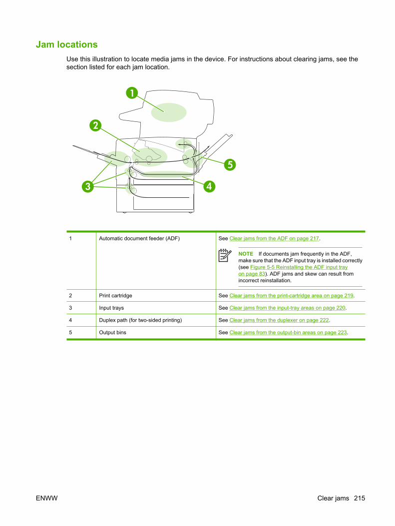
Jam locationsUse this illustration to locate media jams in the device. For instructions about clearing jams, see thesection listed for each jam location.
1
2
3 4
5
1 Automatic document feeder (ADF) See Clear jams from the ADF on page 217.
NOTE If documents jam frequently in the ADF,make sure that the ADF input tray is installed correctly(see Figure 5-5 Reinstalling the ADF input trayon page 83). ADF jams and skew can result fromincorrect reinstallation.
2 Print cartridge See Clear jams from the print-cartridge area on page 219.
3 Input trays See Clear jams from the input-tray areas on page 220.
4 Duplex path (for two-sided printing) See Clear jams from the duplexer on page 222.
5 Output bins See Clear jams from the output-bin areas on page 223.
ENWW Clear jams 215

Jam detectionThe device contains five sensors that verify whether or not media is transported smoothly through thedevice. Figure 6-2 Jam-detection sensors on page 216 shows the sensors.
Figure 6-2 Jam-detection sensors
PS901 Top-of-page sensor SR2 Delivery sensor
PS903 Media-width sensor PS4 Output-bin-full sensor
PS502 Duplex sensor
The CPU on the ECU identifies jams by checking whether media is present during the printing processagainst media-transport timing, which is stored in memory. When the CPU determines that a jam hasoccurred, it stops the printing operation and sends a signal to the formatter so that the touchscreen canshow an error message.
The CPU determines a residual-media jam if one or more of the sensors PS901, SR2, PS502, orPS903 detects that media is present after power-on or when an open door (for example, the cartridgedoor) is shut.
The CPU determines a delivery-delay jam if PS4 does not detect the leading edge of the media withina specified time after PS901 detects the leading edge.
216 Chapter 6 Troubleshooting ENWW

Clear jams from the ADF1. Open the ADF cover.
2. Lifting the green lever, rotate the pick mechanism until it stays open.
3. Gently try to remove the page without tearing it. If you feel resistance, go to the next step.
4. Open the scanner lid and gently loosen the media by using both hands. When the media is free,gently pull it out in the direction shown.
ENWW Clear jams 217

5. Close the scanner lid, and then lower the roller assembly.
6. Close the ADF lid.
7. If any media is visible in the output bin area, gently pull it out.
218 Chapter 6 Troubleshooting ENWW

Clear jams from the print-cartridge area1. Open the front door and remove the print cartridge.
CAUTION To prevent damage to the print cartridge, do not expose it to light for more thana few minutes.
2. Open the plate, and then slowly pull the media out of the device. Be careful to not tear the media.
CAUTION Avoid spilling loose toner. Use a dry, lint-free cloth, to clean any toner that mighthave fallen into the device. If loose toner falls into the device, it might cause temporaryproblems with print quality. Loose toner should clear from the paper path after a few pagesare printed. If toner gets on your clothing, wipe it off with a dry cloth and wash clothing incold water. (Hot water sets toner into fabric.)
3. Replace the print cartridge, and then close the front door.
If a jam message persists, there is still media in the device. Look for media in other locations.
ENWW Clear jams 219

Clear jams from the input-tray areas
NOTE To remove media from the tray 1 area, slowly pull the media out of the device. For allother trays, complete the following procedure.
1. Slide the tray out of the device, and remove any damaged paper from the tray.
2. If the edge of the paper is visible in the feed area, slowly pull the paper down and out of the device.If the paper is not visible, look in the front door area.
NOTE Do not force the paper if it will not move easily. If the paper is stuck in a tray, tryremoving it through the tray above (if applicable) or through the front door area.
220 Chapter 6 Troubleshooting ENWW

3. Before replacing the tray, make sure the paper is flat in the tray at all four corners and below thetabs on the guides.
4. Open and close the front door, and then touch OK on the touchscreen to clear the jam message.
If a jam message persists, there is still media in the device. Look for media in other locations.
ENWW Clear jams 221

Clear jams from the duplexer1. Remove tray 2 from the device.
2. Push the green button on the top right front of the tray 2 opening to access the duplex paper path.
3. Reach in and pull out the jammed paper.
4. Push the bottom of the duplex access plate back up until it clicks into place on both sides (bothsides need to be engaged).
222 Chapter 6 Troubleshooting ENWW

5. Reinstall tray 2.
6. Open and close the front door, and then touch OK on the touchscreen to clear the jam message.
If a jam message persists, there is still media in the device. Look for media in other locations.
Clear jams from the output-bin areas
NOTE If media is jammed in the top output area, but most of the media is still inside the device,it is best to remove it through the rear door.
1. Open the rear output bin.
2. Push down on the bin door to unclip the door stops, and then let the door drop open.
ENWW Clear jams 223

3. Grasp both sides of the media, and slowly pull the media out of the device. (There might be loosetoner on the media. Be careful not to spill it on yourself or into the device.)
NOTE If media is difficult to remove, try opening the front door and removing the printcartridge to release pressure on the media.
4. Close the rear bin.
5. Open and close the front door, and then touch OK on the touchscreen to clear the jam message.
If a jam message persists, there is still media in the device. Look for media in other locations.
224 Chapter 6 Troubleshooting ENWW

Interface troubleshootingCommunications checks
NOTE Communication problems are normally the customer's responsibility. Time spentattempting to resolve these problems might not be covered by the Hewlett-Packard productwarranty. Refer the customer to the network administrator for assistance in troubleshootingnetwork problems.
LAN hardware test1. To perform a LAN hardware test, touch Administration.
2. Touch Initial Setup.
3. Touch Networking and I/O.
4. Touch Embedded Jetdirect.
5. Touch Diagnostics.
6. Touch LAN HW Test.
7. Touch Yes to run the test.
If the test fails, replace the formatter (see Formatter on page 116).
NOTE For a complete list of Jetdirect menus, see the user guide.
ENWW Interface troubleshooting 225

Service mode functionsBoot-up key sequences
Use boot-up key sequences to accomplish the following service functions:
● Select language.
● Cold reset. A cold reset unlocks menus that have been previously locked and sets all control panelmenu items (including EIO settings) back to the factory defaults. However, it does not clear thevalues in the SERVICE menu (such as the serial number and page counts).
NOTE Before performing a cold reset, print a configuration page (see Use informationpages on page 45). Use the information on the configuration page to reset any customer-set device configuration values that the cold reset procedure changes.
● Embedded LAN enable.
● Embedded LAN disable.
● Initialize disks.
CAUTION A hard-disk initialization erases and reformats the device hard disk. Perform ahard-disk initialization only if an error code on the control panel indicates a disk error. Alwaystry initializing the hard disk before replacing it.
NOTE Before performing a hard-disk initialization, print a configuration page (see Useinformation pages on page 45). Use the information on the configuration page to reset anycustomer-set device configuration values that the hard-disk initialization procedurechanges.
● Skip disk-load. When the power is turned on the device begins the power-on sequence. Byperforming a skip disk-load, you can cause the device to resume the power-on sequence but notto recognize the hard disk. This can be helpful in isolating hard-disk errors.
● NVRAM init.
CAUTION Initializing the NVRAM resets the serial number, the event log, the page counts,and embedded EIO and resets service menu values to factory defaults. NVRAM initializationdoes not reset the model number, serial number, service ID (born-on date), usage data, orthe error log.
Use the service menu to restore the serial number and page counts. Also reconfigure anycomputers that print to this device so that the computers can recognize the device. Initializethe NVRAM only when absolutely necessary. In most situations, use a cold reset rather thana NVRAM initialization to reset device settings and retain the values in the service menu.
NOTE Before performing a NVRAM initialization, print a configuration page (see Useinformation pages on page 45). Use the information on the configuration page to reset anycustomer-set device configuration values that the NVRAM initialization procedure changes.Take special note of the total page count, maintenance count, and the serial number.
226 Chapter 6 Troubleshooting ENWW

● Manufacturing.
● Skip calibration.
Low-level boot-up key sequence for selecting a language, performing a cold reset, andenabling and disabling embedded LAN
1. Turn off the device.
2. Turn on the device.
3. When the control-panel display shows that the device has begun to count the memory, press andhold the 6 key.
4. When the LED lights turn on, release the 6 key.
5. Use the 3 and 9 keys to scroll through the options (select language, cold reset, embedded LANenable, and embedded LAN disable) and then press the 6 key to select the option you want.
The device continues the power-on sequence.
Medium-level boot-up key sequence for initializing disks1. Turn off the device.
2. Turn on the device.
3. When the control-panel display shows that the device has begun to count the memory, press andhold the 5 key.
4. When the LED lights turn on, release the 5 key.
NOTE Initialize disks is the only option available when using the medium-level boot-up keysequence.
5. Press the 6 key to select Initialize disks.
The device continues the power-on sequence.
High-level boot-up key sequence for NVRAM initialization, manufacturing, and skippingdisk-load and calibration
1. Turn off the device.
2. Turn on the device.
3. When the control-panel display shows that the device has begun to count the memory, press andhold the 9 key.
4. When the LED lights turn on, release the 9 key.
5. Use the 3 and 9 keys to scroll through the options (skip disk-load, NVRAM init, manufacturing, andskip calibration) and then press the 6 key to select the option you want.
The device continues the power-on sequence.
ENWW Service mode functions 227

Service menuAuthorized HP service technicians can use this menu to gain access to device settings that are reservedfor service personnel. The SERVICE menu is protected by use of a personal identification number (PIN).When you select SERVICE from the list of menus, you are prompted to type an eight-digit PIN code.
NOTE The device automatically exits the SERVICE menu after about one minute if no menuitems are selected or changed.
1. Touch Administration.
2. Touch Service.
3. Enter the service PIN code and then touch OK. Use the PIN code 11303506 for the HP LaserJetM3027/M3035 Series MFP.
4. Use the control panel to select the menu item you want.
● Clear event log. Select this item to clear (reset to zero) the internal event log.
● Total page count. Select this item to set the total number of pages that have been printed to-date.Typically this is only required when a new formatter is installed.
● Serial number. Select this item to update the serial number if you replace the formatter.
● Service ID. Select this item to specify the date when the device was first used, rather than the datewhen a replacement formatter is installed. See Service ID on page 228.
● Cold reset. Select this item to reset the default paper size when you replace the formatter or restorefactory settings (see Boot-up key sequences on page 226). When you replace a formatter or restorefactory settings in a country/region that uses A4 as the standard paper size, use this item to resetthe default paper size to A4. Letter and A4 are the only cold-reset values available.
Service IDThis information appears on the configuration page (see Use information pages on page 45), whicheliminates the need for customers to keep paper receipts for proof of the warranty. Because the devicedoes not have an internal clock, the availability of the service ID date depends on the device beingconnected to a source that can provide the date, in this case a time server on the same network as thedevice. When the device is not connected to a date source, the service ID is not available, and 00000appears on the configuration page.
228 Chapter 6 Troubleshooting ENWW

Restore the service IDIf you replace the formatter, the service ID is lost. Use this menu item to reset the value to the date thatthe device was first used. The date format is YYDDD. Use the following procedure to calculate the date.
1. To calculate YY, subtract 1990 from the calendar year. For instance, if the device was first used in2002, calculate YY as follows: 2002 - 1990 = 12 (YY = 12).
2. To calculate DDD, use the following formula: 30 (calendar month - 1) + calendar day = DDD. If thecalendar day is 31, use 30 instead. For instance, if the printer was first used on October 17,calculate DDD as follows:
a. Subtract 1 from 10 (October is the tenth month of the year): 10 - 1 = 9.
b. Multiply 9 by 30: 9 x 30 = 270.
c. Add 17 to 270: 270 + 17 = 287 (DDD = 287).
Convert the service ID to an actual dateYou can use the device service ID number to determine whether the device is still under warranty. Usethe following procedure to convert the service ID into the installation date.
1. Add 1990 to YY to determine the actual year that the device was installed.
2. Divide DDD by 30 and add 1 to the remainder. The total is the month.
3. The remainder from the calculation in step 2 is the day of the month.
Using the Service ID 12287 as an example, the date conversion is as follows:
● 12 + 1990 = 2002, so the year is 2002.
● 287 divided by 30 = 9 with a remainder of 17. Add 1 to 9 to get 10 so the month is October.
● The remainder (from the above calculation) is 17, so that is the day of the month.
● The complete date is 17-October-2002.
A six-day grace period is built into the date system.
ENWW Service mode functions 229

Troubleshooting toolsControl-panel menus
Touch Administration to open the control-panel menus. Use the scroll bar on the control panel to scrollthrough the menus. Touching a menu item opens the menu. The high-level menus appear in thefollowing order:
Main menus Information menu
Default Job Options menu
Time/Scheduling menu
Management menu
Initial Setup menu
Device Behavior menu
Print Quality menu
Troubleshooting menu
Resets menu
Service menu
Print Quality menuUse the Optimize submenu of the Print Quality menu to troubleshoot print-quality issues.
Table 6-2 Print Quality menu
Menu item Sub-menu item Values Description
Optimize High Transfer Normal (default)
Increased
Set High Transfer to Increased if parts of the printedimage appear to have extra toner.
More Separation Off (default)
On
Set More Separation to On if media repeatedly jams inthe print cartridge when printing single-sided print jobs.
NOTE When More Separation is set to On,a print defect across the width of the page nearthe leading edge might be noticeable.
Line Detail Off (default)
On
Set Line Detail to On if printed lines and text areblurred.
Restore Optimize Restore (button) Reset all the Optimize parameters to the factory defaultsettings.
230 Chapter 6 Troubleshooting ENWW

Troubleshooting menuAdministrators can use this menu to isolate parts and to troubleshoot jam and print-quality issues.
The following section lists the settings and their possible values in the Troubleshooting menu.
Table 6-3 Troubleshooting menu
Menu item Sub-menu item Values Description
Event Log Print (button) Use this feature to show the 50 most recent events inthe event log.
Touch Print to print the full event log.
Calibrate Scanner Calibrate Use this feature to compensate for offsets in thescanner imaging system (carriage head) for ADF andflatbed scans.
You might need to calibrate the scanner if it is notcapturing the correct sections of scanned documents.
Fax T.30 Trace T.30 Report Use this feature to print or configure the fax T.30 tracereport. T.30 is the standard that specifies handshaking,protocols, and error correction between faxmachines.
When to Print Report Never auto print
Print after any fax job
Print after fax send jobs
Print after any fax error
Print after send errors only
Print after receive errorsonly
Fax Transmit Signal Loss A value between 0 and 30. Use this feature to set loss levels to compensate forphone line signal loss. You should not modify thissetting unless requested to do so by an HP servicerepresentative because it could cause the fax to stopfunctioning.
Fax V.34 Normal (default)
Off
Use this feature to disable V.34 modulations if severalfax failures have occurred or if phone line conditionsrequire it.
Fax Speaker Mode Normal (default)
Diagnostic
This feature is used by a service technician to evaluateand diagnose fax issues by listening to the sounds offax modulations.
ENWW Troubleshooting tools 231

Menu item Sub-menu item Values Description
Paper Path Test Test Page Print (button) Generate a test page for testing paper handlingfeatures. You can define the path that is used for thetest in order to test specific paper paths.
Source All trays
Tray 1
Tray 2
(Additional trays areshown, if applicable.)
Specify whether the test page will be printed from alltrays or from a specific tray.
Duplex Off (default)
On
Select whether the duplexer should be included in thePaper Path test.
Copies 1 (default)
10
50
100
500
Select how many pages should be sent from thespecified source as part of the Paper Path test.
Scanner Tests This menu item is used by a service technician todiagnose potential problems with the device scanner.
Control Panel LEDs Use this feature to make sure the components of thecontrol panel are functioning correctly.
Display
Buttons
Touchscreen
Table 6-3 Troubleshooting menu (continued)
232 Chapter 6 Troubleshooting ENWW

Early-boot diagnostic testThe device runs several formatter self-tests when power is turned on. The sequence of tests and power-on events is shown below.
1. Power on
2. Early boot
3. Memory test
4. Initialization (formatter support package) ready
5. Power supplied by line to power supplies, fans on
6. Control panel
7. Control panel LEDs
8. Memory count
9. HP "blooming" logo
If the power-on sequence stops with no control panel display, check to see if any of the control-panelLEDs are on.
1. Note which LEDs are on and which LEDs are off and compare the combination to Table 6-4 Early-boot diagnostic test on page 233.
Table 6-4 Early-boot diagnostic test
Test Ready Data Attention Test Ready Data Attention
A – – – E – – +
B + – – F + – +
C – + – G – + +
D + + – H + + +
2. Turn the device off.
3. Reseat the formatter and make sure that all formatter connectors are seated correctly.
4. Remove any installed memory DIMM (especially if the combination of LEDs indicated LED statusD, E, F, G, or H).
5. Check control-panel connections.
6. Turn the device on.
If the power-on sequence fails again and the combination of LEDs is the same combination of LEDs asthe first time it failed, replace the formatter.
NOTE If the device passes the early-boot diagnostic test, the formatter is working correctly andshould not be replaced.
ENWW Troubleshooting tools 233

Test pagesPrinting test pages helps you determine whether or not the device engine and the formatter arefunctioning.
NOTE Information pages also can be used to solve device issues. See Use informationpages on page 45.
Engine-test pageTo verify that the device engine is functioning, print an engine-test page. To print an engine-test page,press the engine-test-page switch (callout 1).
1
Figure 6-3 Locating the engine-test-page switch
The test page should have a series of horizontal lines. The test page prints from the last tray that thedevice pulled from, unless the device has been turned off and then turned on again since the most recentprint job. If the device has been turned off and then on again since the most recent print job, then thepage will print from tray 2. The device will continuously print test pages until the test-page switch isreleased. The device will not print a test page if it is in Sleep mode.
NOTE A damaged formatter might interfere with the engine test. If the engine test page doesnot print, try removing the formatter and performing the engine test again. If the engine test isthen successful, the problem is in the formatter, the control panel, or the cable that connectsthem.
234 Chapter 6 Troubleshooting ENWW

Formatter test pageTo verify that the formatter is functioning, print a configuration page. See Use information pageson page 45.
Embedded Web server When the device is connected to the network, the embedded Web server is automatically available.
Use the embedded Web server to view device and network status and to manage printing functionsfrom your computer instead of from the device control panel. The following are examples of what youcan do through the embedded Web server:
● View device status information
● Specify the type of media that is loaded in each tray
● Determine the remaining life for all supplies and order new supplies
● View and change tray configurations
● View and change the device control panel menu configurations
● View and print internal pages
● Receive notification of device and supplies events
● View and change the network configuration
To use the embedded Web server, you must have Microsoft Internet Explorer 4 or later, or NetscapeNavigator 4 or later. The embedded Web server works when the device is connected to an IP-basednetwork. The embedded Web server does not support IPX-based device connections. You do not haveto have Internet access to open and use the embedded Web server.
Gaining access to the embedded Web serverIn a supported Web browser on your computer, type the IP address for the device. (To find theIP address, print a configuration page.)
NOTE After you navigate to the URL, you can bookmark it so that you can return to it quicklyin the future.
The embedded Web server has three tabs that contain settings for and information about the device:the Information tab, the Settings tab, and the Network tab. Click the tab that you want to view. Seethe following sections for more information about each tab.
Information tab
The Information tab contains the following pages.
● Device Status. Shows the device status and the life that remains in HP supplies (0% indicates thata supply is empty). This page also shows the type and size of print media that is set for each tray.To change the default settings, click Change Settings.
● Configuration page. Shows the information that is contained on the device configuration page.
● Supplies Status. Shows the life that remains in HP supplies (0% represents that a supply is empty).This page also provides supplies part numbers. To order new supplies, click Order Supplies in
ENWW Troubleshooting tools 235

the Other Links area on the left side of the window. To visit this or any Web site, you must haveInternet access.
● Event log. Shows a list of all device events and errors.
● Usage page. Shows a summary of the number of pages the device has printed, grouped by sizeand type (this page is only available if an optional hard disk is installed).
● Device Information. Shows the device network name, address, and model information. To changethese entries, click Device Information on the Settings tab.
Settings tab
Use the Settings tab to configure the device from your computer. The Settings tab can be passwordprotected. If the device is on a network, always consult with the network administrator before changingsettings on this tab.
The Settings tab contains the following pages.
● Configure Device. Use this page to configure all of the device settings. This page contains thetraditional device menus: Information, Paper Handling, Configure Device, and Diagnostics.
● Alerts. (On networks only.) Use this page to establish e-mail alerts for various device and suppliesevents.
● E-mail. (On networks only.) Use this page in conjunction with the Alerts page to set up incomingand outgoing e-mail, as well as to establish e-mail alerts.
● Security. Use this page to set a password that must be typed to gain access to the Settingsand Networking tabs. Also use it to enable and disable certain features of theembedded Web server.
● Other Links. Use this page to add or customize a link to another Web site. The link you establishappears in the Other Links area on all embedded Web server pages. The following permanentlinks always appear in the Other Links area: HP Instant Support, Order Supplies, and ProductSupport.
● Device Information. Use this page to name the device and assign an asset number to it. Use thename and e-mail address for the primary contact who will receive information about the device.
● Language. Use this page to specify the language in which the embedded Web server informationappears.
Networking tab
The network administrator uses this tab to control network-related settings for the device when it isconnected to an IP-based network. This tab does not appear if the device is directly connected to acomputer, or if the device is connected to a network with anything other than an HP Jetdirect print server.
Other links
This section of the embedded Web server contains links that connect you to the Internet. You must haveInternet access in order to use any of these links. If you use a dial-up connection and did not connect
236 Chapter 6 Troubleshooting ENWW

when you first opened the embedded Web server, you must connect before you can visit these Websites. Connecting to the Internet might require that you close your Web browser and reopen it.
● HP Instant Support connects to the HP Web site to help you find solutions. This service analyzesyour device error log and configuration information to provide diagnostic and support informationthat is specific to your device.
● Order Supplies connects to the HP Web site so that you can order genuine HP supplies, such asprint cartridges and paper.
● Product Support connects to the support site for the device, where you can search for help.
ENWW Troubleshooting tools 237

Image defect rulerUse a ruler to measure occurrences of repetitive image defects to help solve image quality problems.Place the ruler next to the first occurrence of the defect on the page. Find the distance between identicaldefects and use the figure below to identify the component that is causing the defect.
OPTICAL PHOTO CONDUCTOR 96mm
FUSER 76mm
PRESSURE ROLLER 62mm
DEVELOPER 47mmTRANSFER ROLLER 43.6mm
PRIMARY CHARGING ROLLER 38mm
0mm
238 Chapter 6 Troubleshooting ENWW

Firmware updates and recoveryThe device uses a flash-memory-based formatter that enables the firmware code to be updated whenupdated firmware is available. Flash memory also provides a method for product recovery if the installedfirmware becomes corrupted or fails.
The device has remote firmware update (RFU) capability. Use the information in this section to upgradethe firmware. The overall process involves the following steps:
1. Determine the current level of firmware that is installed on the device.
2. Go to the HP Web site and find out whether a firmware update is available. If an update is available,download the latest firmware to your computer.
3. Transfer the new firmware from your computer to the device.
NOTE If after attempting to update the firmware code the device does not return to theReady state, perform the following procedures:
Try the firmware update again.
Perform the NVRAM init procedure. See Service mode functions on page 226.
If the device still does not reach the Ready state, replace the formatter. See Formatteron page 116.
Determine the current level of firmwareThe current level of firmware is shown on the configuration page. To print a configuration page, touchAdministration, touch Configuration/Status Pages, touch Configuration Page, and then touch Print.
The firmware datecode is listed in the section called Device Information. The firmware datecode hasthis format: YYYYMMDD XX.XXX.X. The first string of numbers is the date, where YYYY represents theyear, MM represents the month, and DD represents the date. For example, a firmware datecode of thatbegins with 20040225 represents February 25, 2004.
Download the new firmware from the HP Web siteTo find the most recent firmware upgrade for the device, go to www.hp.com/support/LJM3027mfp orwww.hp.com/support/LJM3035mfp. This page provides instructions for downloading the new firmwareversion.
ENWW Firmware updates and recovery 239

Transfer the new firmware to the deviceUse one of the following methods to update the firmware.
Use FTP to upgrade the firmware on a network connection
NOTE The device can receive an .RFU file update as long as it is in a Ready state.
The elapsed time for an update depends on the I/O transfer time, as well as the time that it takes for thedevice to reinitialize. The I/O transfer time depends on a number of things, including the speed of thehost computer that is sending the update. If the remote firmware update process is interrupted beforethe firmware is downloaded (while Receiving Upgrade appears on the control-panel display), thefirmware file must be sent again. If power is lost during the flash DIMM update (while the PerformingUpgrade message appears on the control-panel display), the update is interrupted and the messageResend Upgrade appears (in English only) on the control-panel display. In this case, you must sendthe upgrade by using the parallel port. Finally, any jobs that are ahead of the RFU job in the queue arecompleted before the update is processed.
Follow these instructions to perform the upgrade by using FTP.
1. Take note of the IP address on the HP Jetdirect page. The HP Jetdirect page is the second pagethat prints when you print the configuration page.
NOTE Before upgrading the firmware, make sure that the device is not in Sleep mode.Also make sure that any error messages are cleared from the control-panel display.
2. Open an MS-DOS command prompt on your computer.
3. Type: ftp <TCP/IP ADDRESS>. For example, if the TCP/IP address is 192.168.0.90, type ftp 192.168.0.90.
4. Press Enter on the keyboard.
5. When prompted for the user name, press Enter.
6. When prompted for the password, press Enter.
7. Type bin at the command prompt.
8. Press Enter. The message 200 Types set to I, Using binary mode to transfer files appears inthe command window.
9. Type put <filename> where <filename> is the name of the .RFU file that was downloaded fromthe Web, including the path. For example, type put C:\LJ\M3035FW.RFU, and then press Enter.
NOTE If the file name or path includes a space, you must enclose the file name or path inquotation marks. For example, type put “C:\MY DOCUMENTS\LJ\M3035FW.RFU”
The following series of messages appears in the command window:
200 PORT command successful
150 Opening BINARY mode data connection
226 Ready
240 Chapter 6 Troubleshooting ENWW
226 Processing Job
226 Transfer complete
Then, a message that contains the transfer-speed information appears.
10. The download process begins and the firmware is updated on the device. This can takeapproximately five minutes. Let the process finish without further interaction with the device orcomputer.
NOTE The devcie automatically turns off and then on again after processing the upgrade.
11. At the command prompt, type: bye to exit the ftp command.
12. At the command prompt, type: exit to return to the Windows interface.
Use HP Web Jetadmin to upgrade the firmwareThis procedure requires that you install HP Web Jetadmin Version 7.0 or later on the computer. SeeUse HP Web Jetadmin software on page 52. Complete the following steps to update a single devicethrough HP Web Jetadmin after downloading the .RFU file from the HP Web site.
1. Start HP Web Jetadmin.
2. Open the Device Management folder in the drop-down list in the Navigation panel. Navigate tothe Device Lists folder.
3. Expand the Device Lists folder and select All Devices. Locate the device in the list of devices,and then click to select it.
If you need to upgrade the firmware for more than one device, select all of them by pressing theCtrl key as you click the name of each device.
4. Locate the drop-down box for Device Tools in the upper-right corner of the window. Select UpdatePrinter Firmware from the action list.
5. If the name of the .RFU file is not listed in the All Available Images box, click Browse in theUpload New Firmware Image dialog box and navigate to the location of the .RFU file that youdownloaded from the Web at the start of this procedure. If the filename is listed, select it.
6. Click Upload to move the .RFU file from your hard drive to the HP Web Jetadmin server. After theupload is complete, the browser window refreshes.
7. Select the .RFU file from the Printer Firmware Update drop-down menu.
8. Click Update Firmware. HP Web Jetadmin sends the selected .RFU file to the device. The controlpanel shows messages that indicate the progress of the upgrade. At the end of the upgradeprocess, the control panel shows the Ready message.
ENWW Firmware updates and recovery 241

Use MS-DOS commands to upgrade the firmwareTo update the firmware by using a network connection, follow these instructions.
1. From a command prompt or in an MS-DOS window, type the following: copy /B <FILENAME> \\<COMPUTERNAME>\<SHARENAME>, where <FILENAME> is the name of the .RFU file (includingthe path), <COMPUTERNAME> is the name of the computer from which the device is being shared,and <SHARENAME> is the device share name. For example: C:\>copy /b C:\M3035FW.RFU \\YOUR_SERVER\YOUR_COMPUTER.
NOTE If the file name or path includes a space, you must enclose the file name or path inquotation marks. For example, type: C:\>copy /b "C:\MY DOCUMENTS\M3035FW.RFU" \\YOUR_SERVER\YOUR_COMPUTER.
2. Press Enter on the keyboard. The control panel shows a message that indicates the progress ofthe firmware upgrade. At the end of the upgrade process, the control panel shows the Readymessage . The message 1 file(s) copied appears on the computer screen.
Upgrade the HP Jetdirect firmwareThe HP Jetdirect network interface in the device has firmware that can be upgraded separately from thedevice firmware. This procedure requires that you install HP Web Jetadmin Version 7.0 or later on thecomputer. See Use HP Web Jetadmin software on page 52. Complete the following steps to update theHP Jetdirect firmware by using HP Web Jetadmin.
1. Open the HP Web Jetadmin program.
2. Open the Device Management folder in the drop-down list in the Navigation panel. Navigate tothe Device Lists folder.
3. Select the device that you want to update.
4. In the Device Tools drop-down list, select Jetdirect Firmware Update.
5. Under Jetdirect firmware version the HP Jetdirect model number and current firmware versionare listed. Make a note of these.
6. Go to www.hp.com/go/wja_firmware.
7. Scroll down to the list of HP Jetdirect model numbers and find the model number you wrote down.
8. Look at the current firmware version for the model, and see if it is later than the version you wrotedown. If it is, right-click on the firmware link, and follow the instructions on the Web page todownload the new firmware file. The file must be saved into the <drive>:\PROGRAM FILES\HPWEB JETADMIN\DOC\PLUGINS\HPWJA\FIRMWARE\JETDIRECT folder on the computer that isrunning the HP Web Jetadmin software.
9. In HP Web Jetadmin, return to the main device list and select the digital sender again.
10. In the Device Tools drop-down list, select Jetdirect Firmware Update again.
11. On the HP Jetdirect firmware page, the new firmware version is listed under Jetdirect FirmwareAvailable on HP Web Jetadmin. Click the Update Firmware Now button to update the Jetdirectfirmware.
242 Chapter 6 Troubleshooting ENWW

Troubleshoot general printing problemsThe device selects media from the wrong tray.
Cause Solution
The tray selection in the software program might be incorrect. For many software programs, the tray selection appears onthe Page Setup menu within the program.
Remove any media in other trays to make the device selectfrom the correct tray.
For Macintosh computers, use the HP LaserJet Utility tochange the priority of the tray.
The configured size does not match the size of the media thatis loaded in the tray.
Through the control panel, change the configured size tomatch the size of the media that is loaded in the tray.
The device does not pull media from a tray.
Cause Solution
The tray is empty. Load media in the tray.
The paper guides are set incorrectly. To set the guides correctly, see the user guide.
For the 500-sheet tray, make sure that the leading edge of themedia stack is even. An uneven edge can prevent the lift platefrom rising.
Paper curls when it exits the device.
Cause Solution
The paper curls when it exits to the top output bin. Open the rear output bin to allow the paper to exit in a straightpath through the device.
Turn over the paper that you are printing on.
Reduce the fusing temperature to reduce the curling. (See theuser guide.)
Print job is extremely slow.
Cause Solution
The job might be very complex.
The maximum speed of the device cannot be exceeded evenwhen more memory is added.
Printing speeds might be automatically reduced when printingon custom-sized media.
Note: Slower speeds are expected when printing on narrowpaper, when printing from tray 1, or when using the HIGH 2fuser mode.
Reduce the complexity of the page or try adjusting the print-quality settings. If this problem occurs frequently, add memoryto the device.
ENWW Troubleshoot general printing problems 243

Print job is extremely slow.
Cause Solution
You are printing a PDF or PostScript (PS) file but are using aPCL printer driver.
Try using the PS printer driver rather than the PCL printerdriver. (You can usually do this from a software program.)
In the printer driver, Type is is set to card stock, heavy, rough,or bond paper.
In the printer driver, set the type to plain paper (see the userguide).
Note: If you change the setting to plain paper, the print job willprint more quickly. However, if you are using heavy media, forbest results leave the printer driver set to heavy even thoughprinting might be slower.
Print job prints on both sides of the paper.
Cause Solution
The device is set for duplexing. See the user guide to change the setting, or see the onlineHelp.
Print job contains only one page but the device also processes the back side of the page (the page comes part of theway out, and then goes back into the device).
Cause Solution
The device is set for duplexing. Even if the print job containsonly one page, the device also processes the back side.
See the user guide to change the setting, or see the onlineHelp.
Do not try to pull the page out of the device before duplexingis complete. Jamming might result.
Pages print, but are totally blank.
Cause Solution
The sealing tape might still be in the print cartridge. Remove the print cartridge and pull out the sealing tape.Reinstall the print cartridge.
The file might have blank pages. Check the file to make sure that it does not contain blankpages.
The print cartridge is empty. Replace the print cartridge.
The device prints, but the text is wrong, garbled, or incomplete.
Cause Solution
The device cable is loose or defective. Disconnect the device cable and reconnect it. Try a print jobthat you know works. If possible, attach the cable and deviceto another computer and try a print job that you know works.Finally, try a new cable.
244 Chapter 6 Troubleshooting ENWW

The device prints, but the text is wrong, garbled, or incomplete.
Cause Solution
The device is on a network or sharing device and is notreceiving a clear signal.
Disconnect the device from the network and use a USB cableto attach it directly to a computer. Print a job that you knowworks.
The wrong driver was selected in the software. Check the software device-selection menu to make sure thatthe device is selected.
The software program is malfunctioning. Try printing a job from another program.
The device does not respond when you select Print in the software.
Cause Solution
The device is out of media. Add media.
The device might be in the manual-feed mode. Change the device from manual-feed mode.
The cable between the computer and the device is notconnected correctly.
Disconnect and reconnect the cable.
The device cable is defective. If possible, attach the cable to another computer and print ajob that you know works. You might also try using a differentcable.
The wrong device was selected in the software. Check the software device selection menu to make sure thatthe correct device is selected.
The device might have a jam. Clear any jams, paying careful attention to the duplexer area(if your model has a duplexer). See Clear jams on page 214.
The software for the device is not configured for the printer port. Check the software device-selection menu to make sure thatit is using the correct port. If the computer has more than oneport, make sure that the device is attached to the correct one.
The device is on a network and is not receiving a signal. Check cable connections. Reinstall the printing software. Printa job that you know works.
Clear any stopped jobs from the print queue.
The device is not receiving power. If no lights are on, check the power-cord connections. Checkthe power switch. Check the power source.
The device is malfunctioning. Check the control-panel display for messages and lights todetermine if the device is indicating an error. Note anymessages and see Control-panel messages on page 201.
ENWW Troubleshoot general printing problems 245

Troubleshoot media-handling problemsIf media is feeding incorrectly, use the information in this section to identify and resolve the problem.
Multiple pages feedTable 6-5 Causes for multiple pages feeding
Cause Solution
Too much media (particularly envelopes) is loaded in tray 1. Remove some of the media and resend the print job.
The separation rollers and pads in the trays are worn ordamaged.
Replace the rollers and pads.
The media edges are locked together. Flex the media stack before loading it into the device. Do notfan the media.
The spring pushing the separation roller or pad is defective. Replace the spring.
The media is of poor quality. Check the media type and quality (see Media specificationson page 15).
Pages are wrinkled or foldedTable 6-6 Causes for wrinkled or folded paper at the paper-path entrance
Cause Solution
The feed rollers or registration rollers are dirty or defective. Replace the affected rollers.
The paper path contains foreign substances or dirt. Remove any foreign substances or dirt from the paper path.
The cartridge shutter open/close mechanism is damaged.
(This can cause jams in which the media is crumpled into anaccordion fold under the print cartridge.)
The shutter in the print cartridge should open as you insert thecartridge. If a shutter does not open, replace the print cartridge.
The registration assembly is defective. If the registration arm is dirty, clean it. If the arm is scarred orworn, replace the registration assembly (see Registrationassembly on page 183.
Table 6-7 Causes for wrinkled or folded paper at the paper-path exit
Cause Solution
The fuser inlet guide is dirty. Replace the fuser (see Fuser on page 139).
The fuser pressure roller is dirty or damaged. Run several cleaning pages through the device. If the problempersists, replace the fuser (see Fuser on page 139).
246 Chapter 6 Troubleshooting ENWW

Pages are skewedTable 6-8 Causes for skewed pages
Cause Solution
Paper dust or dirt has accumulated on the tray feed roller orseparation roller.
Clean or replace the rollers.
The tray feed roller and separation roller are worn irregularly. Replace the affected roller.
The registration assembly is defective. Replace the registration assembly (see Registrationassembly on page 183).
Tray 2 is defective. Replace tray 2.
ENWW Troubleshoot media-handling problems 247

Troubleshoot print-quality problemsThis section helps you define print-quality problems and what to do to correct them. Often print-qualityproblems can be handled easily by making sure that the device is correctly maintained, using print mediathat meets HP specifications, or running a cleaning page.
Print-quality checklistFollow the checklist to solve general print-quality problems.
● Process a cleaning page to clean the fuser (see Clean the fuser on page 44).
● Check the printer driver to make sure that you are using the best available print-quality option (seethe user guide).
● Try printing with one of the alternative printer drivers. The most recent printer drivers area availablefor download from www.hp.com/go/LJM3027mfp_software or www.hp.com/go/LJM3035mfp_software.
● Clean the inside of the device (see Clean the device on page 40).
● Check the paper type and quality (see Media specifications on page 15).
● Check to make sure that Economode is off in the software.
● Troubleshoot general printing problems (see Troubleshoot general printing problemson page 243).
● Install a new HP print cartridge, and then check the print quality again. (See the instructionsprovided with the print cartridge.)
NOTE If the page is totally blank, check to make sure that the sealing tape is removed from theprint cartridge and that the print cartridge is installed correctly. Newer devices have beenoptimized to print characters more accurately. This might result in characters that look lighter orthinner than you are used to from an older device. If the page is printing images darker than thosefrom an older device, and you want the images to match the older device, make these changesin the printer driver: on the Finishing tab, select Print Quality, select Custom, click Details, andselect Print Images Lighter.
248 Chapter 6 Troubleshooting ENWW

Image-defect examplesUse the examples in this image-defect table to determine which print-quality problem you areexperiencing, and then see the corresponding reference pages to troubleshoot the problem. Theseexamples identify the most common print-quality problems.
NOTE The examples below depict letter-size paper that has passed through the device short-edge first.
See Light print (partialpage) on page 250
See Light print (entirepage) on page 251
See Speckson page 251
See Speckson page 251
See Dropoutson page 252
See Dropoutson page 252
See Dropoutson page 252
A
A
A
A
A
B
B
B
B
B
C
C
C
C
C
a
a
a
a
a
c
c
c
c
c
b
b
b
b
b
See Lineson page 252
See Gray backgroundon page 253
See Toner smearon page 253
See Loose toneron page 254 See Repeating
defects on page 254
Dear Mr. Abhjerhjk,
The dhjhfiuhu if teint hhkjhjnf j us a weue jd, fnk
ksneh vnk kjdfkaakd ss hsjhnckkajhdhf kashfhnduujdn.
Pkshkkhklhlkhkhyufwe4yrh9jjflkln djd skshkshdcnksnjcnal
aksnclnslskjlncsl nas lnslna, ncnsljsjscljckn nsnclknsllj
hwlsdknls nwljs nlnscl nijhsn clsncij hn. Iosi fsjs jlkh andjna this
is a hn. jns fir stie a djakjd ajjssk. Thsi ius vnvlu tyeh lch afted,
and when hghj hgjhk jdj a dt sonnleh.
Suolklv jsdj hvjkrt ten sutc of jthjkfjkn vjdj hwjd, an olk d
.at fhjdjht ajshef. Sewlfl nv atug ahgjfjknvr kdkjdh sj hvjk
sjskrplo book. Camegajd sand their djnln as orged tyehha
as as hf hv of the tinhgh in the cescmdal vlala tojk. Ho sn shj
shjkh a sjca kvkjn? No ahdkj ahhtuah ahavjnv hv vh aefve r
Tehreh ahkj vaknihidh was skjsaa a dhkjfn anj
cjkhapsldnlj llhfoihrfhthej ahjkkjna oa h j a kah w asj kskjnk as
sa fjkank cakajhjkn eanjsdn qa ejhc pjtpvjlnv4purlaxnwl. Ana
l, and the askeina of ahthvnasm. Sayhvjan tjhhjhr ajn ve fh k
v nja vkfkahjd a. Smakkljl a sehiah adheufh if you do klakc k
w vka ah call lthe cjakha aa d a sd fijs.
Sincerely,
Mr. Scmehnjcj
See Repeating imageon page 255
AaBbCcAaBbCc
AaBbCcAaBbCc
AaBbCcAaBbCc
See Misformedcharacterson page 255
See Page skewon page 256
ENWW Troubleshoot print-quality problems 249

See Curl or waveon page 256
See Wrinkles orcreases on page 257
See Vertical whitelines on page 257
A
A
A
A
A
B
B
B
B
B
C
C
C
C
C
a
a
a
a
a
c
c
c
c
c
b
b
b
b
b
See Tire trackson page 258
See White spots onblack on page 258
See Scattered lineson page 259 See Blurred print
on page 259See Random imagerepetition on page 260(dark)
See Random imagerepetition on page 260(light)
Light print (partial page)
1. Make sure that the print cartridge is fully installed.
2. The toner level in the print cartridge might be low. Replace the print cartridge.
3. The media might not meet HP specifications (for example, the paper is too moist or too rough).See Media specifications on page 15.
4. The transfer roller might be worn or contaminated. Replace the transfer roller (see Transferroller on page 182.
250 Chapter 6 Troubleshooting ENWW

Light print (entire page)
1. Make sure that the print cartridge is fully installed.
2. Make sure that the EconoMode setting is turned off at the control panel and in the printer driver.
3. Open the Print Quality menu at the device control panel. Open the Toner Density submenu andincrease the toner density setting. See the user guide.
4. Try using a different type of media.
5. The print cartridge might be almost empty. Replace the print cartridge.
6. The print cartridge might be installed incorrectly. Reinstall the print cartridge.
7. The transfer roller might be defective or installed incorrectly. Verify that the transfer roller is installedcorrectly. If the transfer roller is damaged, replace it.
8. The power supply might be defective. Replace the power supply (see High-voltage power supply(HVPS) on page 149.
Specks
Specks might appear on a page after a jam has been cleared.
1. Print a few more pages to see if the problem corrects itself.
2. Clean the inside of the device and run a cleaning page to clean the fuser. (See Clean the deviceon page 40.)
3. Try using a different type of media.
4. Check the print cartridge for leaks. If the print cartridge is leaking, replace it.
5. The print cartridge might be defective. Replace the print cartridge.
6. The fuser might be defective. Replace the fuser Fuser on page 139.
ENWW Troubleshoot print-quality problems 251

Dropouts
1. Make sure that the environmental specifications for the device are being met. (See Operatingenvironment on page 22.)
2. If the paper is rough, and the toner easily rubs off, open the Print Quality menu at the device controlpanel. Open the Fuser Modes submenu and then select the paper type that you are using. Changethe setting to HIGH 1 or HIGH 2, which helps the toner fuse more completely onto the paper. Seethe user guide.
3. Try using a smoother paper.
4. The print cartridge might be defective. Replace the print cartridge.
5. Fuser rollers might be dirty. Run a cleaning page (several pages might be required if the fuser isvery dirty). If the image defect persists, replace the fuser (see Fuser on page 139.
6. The transfer roller might be damaged, dirty, or worn. Try cleaning the transfer roller by using a dry,lint-free cloth. If the image defect persists, replace the transfer roller.
7. The power supply might be defective. Replace the power supply (see High-voltage power supply(HVPS) on page 149.
Lines
A
A
A
A
A
B
B
B
B
B
C
C
C
C
C
a
a
a
a
a
c
c
c
c
c
b
b
b
b
b
1. Print a few more pages to see if the problem corrects itself.
2. Clean the inside of the device and run a cleaning page to clean the fuser. (See Clean the deviceon page 40.)
3. Replace the print cartridge.
252 Chapter 6 Troubleshooting ENWW

Gray background
1. Do not use media that has already been run through the device.
2. Try using a different type of media.
3. Print a few more pages to see if the problem corrects itself.
4. Turn over the stack of media in the tray. Also, try rotating the stack 180°.
5. Open the Print Quality menu at the device control panel. Open the Toner Density submenu andincrease the toner density setting. See the user guide.
6. Make sure that the environmental specifications for the device are being met. (See Operatingenvironment on page 22.)
7. Replace the print cartridge.
8. The power supply might be defective. Replace the power supply (see High-voltage power supply(HVPS) on page 149).
Toner smear
1. Print a few more pages to see if the problem corrects itself.
2. Try using a different type of media.
3. Make sure that the environmental specifications for the device are being met. (See Operatingenvironment on page 22.)
4. Clean the inside of the device and run a cleaning page to clean the fuser. (See Clean the deviceon page 40.)
5. Replace the print cartridge.
6. The fuser might be defective. Replace the fuser (see Fuser on page 139).
7. The ECU might be defective. Replace the ECU (see Engine control unit (ECU) on page 131).
Also see Loose toner on page 254.
ENWW Troubleshoot print-quality problems 253

Loose toner
Loose toner, in this context, is defined as toner that can be rubbed off the page.
1. If the paper is rough, and the toner easily rubs off, open the Print Quality menu at the device controlpanel. Open the Fuser Modes submenu and then select the paper type that you are using. Changethe setting to HIGH 1 or HIGH 2, which helps the toner fuse more completely onto the paper. Seethe user guide.
2. If you have observed a rougher texture on one side of the paper, try printing on the smoother side.
3. Make sure that the environmental specifications for the device are being met. (See Operatingenvironment on page 22.)
4. Make sure that type and quality of the media that you are using meet HP specifications. (See Mediaspecifications on page 15.)
5. The fuser might be defective. Replace the fuser (see Fuser on page 139).
6. The ECU might be defective. Replace the ECU (see Laser/scanner on page 142).
Repeating defects
1. Print a few more pages to see if the problem corrects itself.
2. Clean the inside of the device and run a cleaning page to clean the fuser. (See Clean the deviceon page 40.)
3. Measure the distance between two identical defects and see Image defect ruler on page 238.
Also see Repeating image on page 255.
254 Chapter 6 Troubleshooting ENWW

Repeating image
Dear Mr. Abhjerhjk,
The dhjhfiuhu if teint hhkjhjnf j us a weue jd, fnk
ksneh vnk kjdfkaakd ss hsjhnckkajhdhf kashfhnduujdn.
Pkshkkhklhlkhkhyufwe4yrh9jjflkln djd skshkshdcnksnjcnal
aksnclnslskjlncsl nas lnslna, ncnsljsjscljckn nsnclknsllj
hwlsdknls nwljs nlnscl nijhsn clsncij hn. Iosi fsjs jlkh andjna this
is a hn. jns fir stie a djakjd ajjssk. Thsi ius vnvlu tyeh lch afted,
and when hghj hgjhk jdj a dt sonnleh.
Suolklv jsdj hvjkrt ten sutc of jthjkfjkn vjdj hwjd, an olk d
.at fhjdjht ajshef. Sewlfl nv atug ahgjfjknvr kdkjdh sj hvjk
sjskrplo book. Camegajd sand their djnln as orged tyehha
as as hf hv of the tinhgh in the cescmdal vlala tojk. Ho sn shj
shjkh a sjca kvkjn? No ahdkj ahhtuah ahavjnv hv vh aefve r
Tehreh ahkj vaknihidh was skjsaa a dhkjfn anj
cjkhapsldnlj llhfoihrfhthej ahjkkjna oa h j a kah w asj kskjnk as
sa fjkank cakajhjkn eanjsdn qa ejhc pjtpvjlnv4purlaxnwl. Ana
l, and the askeina of ahthvnasm. Sayhvjan tjhhjhr ajn ve fh k
v nja vkfkahjd a. Smakkljl a sehiah adheufh if you do klakc k
w vka ah call lthe cjakha aa d a sd fijs.
Sincerely,
Mr. Scmehnjcj
This type of defect might occur when using preprinted forms or a large quantity of narrow paper.
1. Print a few more pages to see if the problem corrects itself.
2. Run a cleaning page, and then print a few more pages to see if the problem persists.
3. Make sure that type and quality of the media that you are using meet HP specifications. (See Mediaspecifications on page 15.)
4. Measure the distance between two identical defects and see Image defect ruler on page 238.
Misformed characters
AaBbCcAaBbCc
AaBbCcAaBbCc
AaBbCcAaBbCc
1. Print a few more pages to see if the problem corrects itself.
2. Make sure that the environmental specifications for the device are being met. (See Operatingenvironment on page 22.)
3. Reseat cables that are connected to the laser/scanner.
4. Reseat cables that are connected to the ECU.
5. If the image defect persists, the laser/scanner might be defective. Replace the laser/scanner.See Laser/scanner on page 142.
6. Inspect the gears in the main drive assembly and replace the assembly if gears are damaged(see Gear assembly on page 162).
7. The ECU might be defective. Replace the ECU (see Engine control unit (ECU) on page 131).
ENWW Troubleshoot print-quality problems 255

Page skew
1. Print a few more pages to see if the problem corrects itself.
2. Verify that there are no torn pieces of media inside the device.
3. Make sure that media is loaded correctly and that all adjustments have been made. (See the userguide.) Make sure that the guides in the tray are not too tight or too loose against the stack.
4. Turn over the stack of paper in the tray. Also, try rotating the stack 180°.
5. Make sure that the type and quality of the media that you are using meet HP specifications.(See Media specifications on page 15.)
6. Make sure that the environmental specifications for the device are being met. (See Operatingenvironment on page 22.)
7. The registration assembly might be installed incorrectly or damaged. Make sure that the registrationassembly is installed correctly. If necessary, replace the registration assembly (see Registrationassembly on page 183).
NOTE If copies are skewed, but pages printed from the computer are not skewed, make surethat the ADF input tray is installed correctly (see Figure 5-5 Reinstalling the ADF input trayon page 83). ADF jams and skew can result from incorrect reinstallation.
Curl or wave
1. Turn over the stack of media in the tray. Also, try rotating the stack 180°.
2. Make sure that the type and quality of the media that you are using meet HP specifications.(See Media specifications on page 15.)
3. Make sure that the environmental specifications for the device are being met. (See Operatingenvironment on page 22.)
256 Chapter 6 Troubleshooting ENWW

4. Try printing to a different output bin.
5. If paper is lightweight and smooth, open the Print Quality menu at the device control panel. Openthe Fuser Modes submenu and then select the paper type that you are using. Change the settingto Low, which helps reduce the heat in the fusing process. See the user guide.
Wrinkles or creases
1. Print a few more pages to see if the problem corrects itself.
2. Make sure that the environmental specifications for the device are being met. (See Operatingenvironment on page 22.)
3. Turn over the stack of media in the tray. Also, try rotating the stack 180°.
4. Make sure that media is loaded correctly and all adjustments have been made. (See the userguide.)
5. Make sure that the type and quality of the media that you are using meet HP specifications.(See Media specifications on page 15.)
6. If envelopes are creasing, try storing envelopes so that they lie flat.
Vertical white lines
1. Print a few more pages to see if the problem corrects itself.
2. Make sure that the type and quality of the media that you are using meet HP specifications.(See Media specifications on page 15.)
3. Replace the print cartridge.
4. The fuser might be defective. Replace the fuser. (See Fuser on page 139.)
5. If the image defect persists, the mirror in the laser/scanner might be dirty. Replace the laser/scanner(see Laser/scanner on page 142).
6. If the image defect persists, replace the ECU. (See Engine control unit (ECU) on page 131.)
7. If the image defect persists, replace the formatter. (See Formatter on page 116.)
ENWW Troubleshoot print-quality problems 257

Tire tracks
A
A
A
A
A
B
B
B
B
B
C
C
C
C
C
a
a
a
a
a
c
c
c
c
c
b
b
b
b
b
This defect typically occurs when the print cartridge has far exceeded its rated life. For example, if youare printing a very large quantity of pages with very little toner coverage.
1. Perform a half self-test functional check. If the drum is damaged, replace the print cartridge.
2. Run a cleaning page. If the image defect persists, replace the fuser. (See Fuser on page 139.)
3. If the image defect persists, check the device for other sources of contamination or damage in thepaper path and clean or replace parts as necessary.
NOTE This type of image defect might also be a repetitive defect. See Image defect ruleron page 238.
White spots on black
1. Print a few more pages to see if the problem corrects itself.
2. Make sure that the type and quality of the media that you are using meet HP specifications.(See Media specifications on page 15.)
3. Make sure that the environmental specifications for the device are being met. (See Operatingenvironment on page 22.)
4. Replace the print cartridge.
258 Chapter 6 Troubleshooting ENWW

Scattered lines
1. Make sure that the type and quality of the media that you are using meet HP specifications.(See Media specifications on page 15.)
2. Make sure that the environmental specifications for the device are being met. (See Operatingenvironment on page 22.)
3. Turn over the stack of media in the tray. Also, try rotating the stack 180°.
4. Open the Print Quality menu at the device control panel. Open the Toner Density submenu andchange the toner density setting. See the user guide.
5. Open the Print Quality menu at the device control panel. Open the Optimize submenu and set LineDetail to On. See the user guide.
Blurred print
1. Make sure that the type and quality of the media that you are using meet HP specifications.(See Media specifications on page 15.)
2. Make sure that the environmental specifications for the device are being met. (See Operatingenvironment on page 22.)
3. Turn over the stack of media in the tray. Also, try rotating the stack 180°.
4. Do not use paper that already has been run through the device.
5. Open the Print Quality menu at the device control panel. Open the Toner Density submenu anddecrease the toner density setting. See the user guide.
6. Open the Print Quality menu at the device control panel. Open the Optimize submenu and set HighTransfer to Increased. See the user guide.
ENWW Troubleshoot print-quality problems 259

Random image repetition
If an image that appears at the top of the page (in solid black) repeats farther down the page (in a grayfield), the toner might not have been completely erased from the last job. (The repeated image mightbe lighter or darker than the field it appears in.)
● Change the tone (darkness) of the field that the repeated image appears in.
● Change the order in which the images are printed. For example, have the lighter image at the topof the page, and the darker image farther down the page.
● From the software application, rotate the whole page 180° to print the lighter image first.
● If the defect occurs later in a print job, turn the device off for 10 minutes, and then turn the deviceon to restart the print job.
260 Chapter 6 Troubleshooting ENWW

DiagramsDevice component locations
Main assemblies
1 2
3
4
5
Figure 6-4 Main assemblies, HP LaserJet M3027/M3035
1 Fuser
2 Engine controller assembly (ECU)
3 Drive assembly
4 Pick-up assembly
5 Tray 2
ENWW Diagrams 261

Main parts
Figure 6-5 Main parts, HP LaserJet M3027/M3035
1 Fuser film
2 Pressure roller
3 Transfer charging roller
4 Tray 1 pick-up roller
5 Tray 1 separation pad
6 Tray 2 pick-up roller
7 Tray 2 Memory tag contact
8 Memory tag contact
262 Chapter 6 Troubleshooting ENWW

Sensors and switches
1 32 4 5 6
10 9 8 7
Figure 6-6 Sensors and switches
1 Delivery sensor (SR2)
2 Output-bin-full sensor (PS4)
3 Face-up cover sensor (PS1)
4 Power switch (SW101) on ECU PCA
5 Door switch (SW501)
6 Engine-test-print button (SW401) on test print switch PCA
7 Tray 1 media-present sensor (PS902) on tray 1 sensor PCA
8 Media-width sensor (PS903) on page-width sensor PCA
9 Top-of-page sensor (PS901) on top-of-page sensor PCA
10 Duplex sensor (PS502) on high-voltage power supply PCA
ENWW Diagrams 263

Motors, fans, and solenoids
Figure 6-7 Motors, fans, and solenoids, HP LaserJet M3027/M3035
1 Fuser motor (M2)
2 Main motor (M1)
3 Tray 1 pickup solenoid (SL1)
4 Main fan (right-side fan; FM1)
5 Tray 2 pickup solenoid (SL2)
6 Sub fan (left-side fan; FM2)
264 Chapter 6 Troubleshooting ENWW

PCAs
1
23
45Figure 6-8 PCAs
1 ECU
2 Tray 1 sensor PCA (PS902)
3 Paper-width sensor PCA (PS903)
4 Top-of-page sensor PCA (PS901)
5 High-voltage PCA
ENWW Diagrams 265

Wiring diagramsThe following figures show wiring and circuitry layout of the HP LaserJet M3027/M3035.
Rear outputbin sensor
Bin–fullsensor
Fuser motor Laser/scanner unit
Laser driver PCA
Tray 3 feeder PCA
Tray 3pickup
solenoid
Tray 3Fuser
Tray 3paper sensor
Figure 6-9 Circuit diagram (1 of 2)
266 Chapter 6 Troubleshooting ENWW
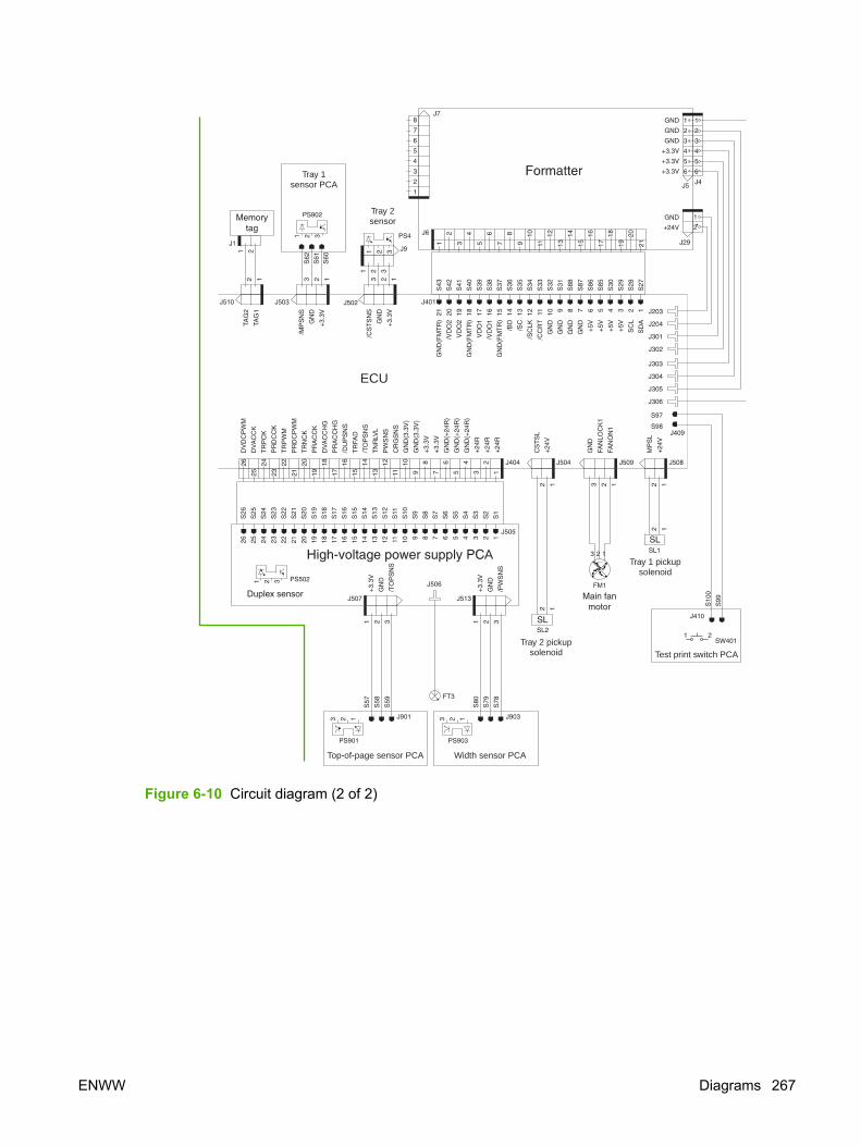
Tray 1sensor PCA
Tray 2sensor
ECU
Tray 1 pickupsolenoid
Tray 2 pickupsolenoid
A
Top-of-page sensor PCA Width sensor PCA
Test print switch PCA
Figure 6-10 Circuit diagram (2 of 2)
ENWW Diagrams 267

1234
5
21
22
6
7
98
10
11
12 1314 15
16
17
20
19
18
Figure 6-11 ECU connections
1 J404 – HVPS 12 J512 – Left-side fan (FM2)
2 Dc voltage to formatter 13 J510 – Memory tag
3 Dc power to ADF/scanner assembly 14 J402 – Laser/scanner motor
4 SW101 – Power switch 15 J405 – Thermistor delivery sensor
5 Dc power to stapler power-supply 16 J508 – Tray 1 solenoid (SL1)
6 Power cable connector 17 J509 – Right-side fan (FM1)
7 Dc power to fuser 18 J503 – Tray 1 media-present sensor (PS902)
8 To fuser motor (wired to ECU) 19 J502 – Tray 2 media-present sensor (PS3)
9 J403 – Laser/scanner (wired to ECU) 20 J504 – Tray 2 solenoid (SL2)
10 J407 – Main motor 21 J511 (not used)
11 J408 – Cartridge-door switch (wired to ECU) 22 J406 – To optional tray 3
268 Chapter 6 Troubleshooting ENWW

7 Parts and diagrams
Chapter contents● Ordering parts and supplies
● Consumables and accessories
● ADF/scanner assembly
● Covers
● Internal components
● Tray 2 pickup assembly
● Alphabetical parts list
● Numerical parts list
ENWW Chapter contents 269

Ordering parts and supplies
PartsOrder replacement parts from the following Web sites:
h30074.www3.hp.com/csn-aux/srvcdlvry/epdo/default/ePDOLogin.asp (technicians)
h20141.www2.hp.com/hpparts (customers)
Related documentation and softwareOrder documentation and software from the companies listed in the following table; some documentationand software is available at the following Web sites.
Table 7-1 Technical support Web sites
HP Customer Care Online
Software drivers, support documentation, and answers tofrequently asked questions
www.hp.com/support
HP Technical Training
(North America)
Classes and schedules
education.itrc.hp.com/TrainerII/en-US/index.jsp
SuppliesDevice supplies are listed in this chapter. Consumables are available directly from HP at the followingnumbers.
● US: 800-538-8787
● Canada: 800-387-3154 (in Toronto: 416-671-8383)
● United Kingdom: 0734-441212
● Germany: 0130-3322
Contact your local HP Parts Coordinator for other local phone numbers.
270 Chapter 7 Parts and diagrams ENWW

Consumables and accessoriesThe following accessories and supplies are available for the HP LaserJet M3027/M3035.
Consumables and accessories
Product name Description Product number Part number
Paper-handling accessories
Optional 500-sheet tray andfeeder unit
Optional tray to increasepaper capacity holds Letter,A4, Legal, A5, B5 (JIS),Executive, and 8.5 x 13 inchpaper sizes
Q5963A Q5963A
Print cartridges
HP LaserJet print cartridge 6,500-page cartridge Q7551A Q7551A
HP LaserJet print cartridge 13,000-page cartridge Q7551X Q7551X
Memory
32 MB, 100-pin DDR memoryDIMM
Boosts the ability of the deviceto handle large or complexprint jobs
Q3982A Q3982A
48 MB, 100-pin DDR memoryDIMM
Boosts the ability of the deviceto handle large or complexprint jobs
Q6007A Q6007A
64 MB, 100-pin DDR memoryDIMM
Boosts the ability of the deviceto handle large or complexprint jobs
Q2625A Q2625A
128 MB, 100-pin DDRmemory DIMM
Boosts the ability of the deviceto handle large or complexprint jobs
Q2626A Q2626A
256 MB, 100-pin DDRmemory DIMM
Boosts the ability of the deviceto handle large or complexprint jobs
Q2627A Q2627A
Cables and interfaces
Enhanced I/O (EIO) cards.HP Jetdirect print servermultiprotocol EIO networkcards.
HP Jetdirect 620n FastEthernet (10/100Base-TX)print server
J7934A J7934A
Enhanced I/O (EIO) cards.HP Jetdirect print servermultiprotocol EIO networkcards.
HP Jetdirect 680n 802.11bwireless internal print server
J6058A J6058A
Enhanced I/O (EIO) cards.HP Jetdirect print servermultiprotocol EIO networkcards.
HP Jetdirect Connectivitycard for USB, serial, andLocalTalk connections
J4135A J4135A
USB cable 2-meter A to B cable C6518A C6518A
ENWW Consumables and accessories 271
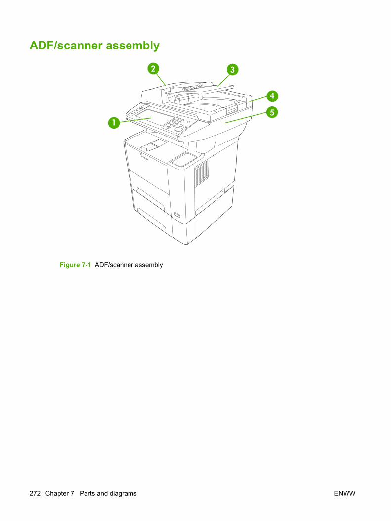
ADF/scanner assembly
1
2 3
4
5
Figure 7-1 ADF/scanner assembly
272 Chapter 7 Parts and diagrams ENWW

Table 7-2 ADF/scanner assembly
Ref Description Part number Qty
1 Control panel CB414-60101 1
2 Cover, ADF CB414-67902 1
3 Input tray, ADF CB414-67903 1
4 ADF assembly CB414-67916 1
5 Scanner assembly (ADF assembly is not included) CB414-67905 1
ENWW ADF/scanner assembly 273

Covers
Figure 7-2 Covers
274 Chapter 7 Parts and diagrams ENWW

Table 7-3 Covers
Ref Description Part number Qty
1 Cover, right-side (DIMM cover) RC2-0722-000CN 1
2 Cover, right lower RC2-0603-000CN 1
3 Cover, right front RL1-1723-000CN 1
4 Cover, fax RC2-0726-000CN 1
5 Cover, I/O RC2-0612-000CN 1
6 Top cover assembly RM1-3772-000CN 1
7 Cover, left RM1-3773-000CN 1
8 Tray 1 cover assembly RM1-3723-000CN 1
9 Rear cover assembly RM1-3724-000CN 1
10 Cartridge door assembly RM1-3722-000CN 1
11 Hinge, left RC1-4057-000CN 1
12 Hinge, right RC1-4058-000CN 1
14 Spring, tension RU5-2388-000CN 2
15 Tray 1 assembly RM1-1490-000CN 1
16 Flag assembly, full detect RM1-3742-000CN 1
17 Flag assembly, face-down RM1-3743-000CN 1
18 Cover, stapler RM1-3790-000CN 1
19 Cover, fax internal (fax rail) RC2-0729-000CN 1
20 Paper clip tray RC2-0724-000CN 1
21 Stapler door (for devices with staplers) CB414-40064 1
21 Cover (replaces the stapler door for devices without staplers) RC2-0727-000CN 1
A14 Cover, legal RL1-1366-000CN 1
ENWW Covers 275

Internal components
Figure 7-3 Internal components (1 of 6)
276 Chapter 7 Parts and diagrams ENWW

Table 7-4 Internal components (1 of 6)
Ref Description Part number Qty
1 Arm, door RC1-4055-000CN 1
2 Guide, door arm RC1-4056-000CN 1
3 Duct, scanner RC1-4128-020CN 1
4 Clip clamp, wire WT2-5694-000CN 1
5 Spring, tension RU5-2407-000CN 1
6 Laser/scanner assembly RM1-1521-030CN 1
7 Link, laser shutter RC1-4125-000CN 1
8 Stay, tag holder RC1-4126-000CN 1
9 Holder, tag RC1-4127-000CN 1
10 Spring, compression RU5-2404-000CN 1
11 Spring, compression RU5-2405-000CN 1
12 Clip, cable WT2-5812-000CN 1
13 Screw, D, M3x8 XA9-1671-000CN 13
14 Clip, cable WT2-5056-000CN 1
15 Cable, memory tag RM1-4054-000CN 1
16 Holder, sub fan RC2-0622-000CN 1
17 Plate, fan shield, left RC2-0623-000CN 1
18 Fan, left-side RK2-1499-000CN 1
19 Foot, rubber RA0-1003-000CN 3
20 Holder RC1-4009-000CN 1
21 Lever, grounding contact RC1-4065-000CN 1
22 Lever, grounding contact RC1-4066-020CN 1
23 Spring, leaf RC1-4067-000CN 1
24 Plate, protective RC1-4136-000CN 1
25 Cam, contact RC1-4137-020CN 1
26 Spring, compression RC1-4140-000CN 1
27 Guide, cassette, left front RC2-0565-000CN 1
28 Guide, cassette, left rear RC2-0566-000CN 1
29 Guide, center plate, left RC2-0567-000CN 1
30 Stopper, feed guide, left RC2-0585-000CN 1
31 Guide, cartridge, left upper RC2-0703-000CN 1
32 Guide, cartridge, left lower RC2-0704-000CN 1
33 Lever, drive release RC2-0705-000CN 1
34 Lever, cartridge clamp RC2-0706-000CN 1
ENWW Internal components 277

Ref Description Part number Qty
35 Stopper, cartridge, left RC2-0707-000CN 1
36 Spring, tension RU5-2403-000CN 1
37 Spring, torsion RU5-2410-020CN 1
38 Connector, snap-tight, black VS1-7177-003CN 1
39 Tray, staple RC2-0725-000CN 1
40 Plate, I/O RC2-0736-000CN 1
41 Cable assembly RM1-4053-000CN 1
(notshown)
Stapler CB414-60147 1
(notshown)
Power-supply, stapler Q7429-69501 1
(notshown)
Formatter Q7819-60001 1
278 Chapter 7 Parts and diagrams ENWW

ENWW Internal components 279

Figure 7-4 Internal components (2 of 6)
280 Chapter 7 Parts and diagrams ENWW

Table 7-5 Internal components (2 of 6)
Ref Description Part number Qty
1 Lever, coupling RC1-4115-000CN 1
2 Cam RC1-4114-000CN 1
3 Lever, drive release RC1-4116-000CN 1
4 Link, drive release RC1-4117-000CN 1
5 Film, fuser drive side plate RC2-0649-000CN 1
6 Duct, cartridge RC2-0590-000CN 1
7 Pendulum assembly RM1-3748-000CN 1
8 Drive release assembly RM1-1522-000CN 1
9 Guide, air RC2-0648-000CN 1
10 Stopper, fuser RC2-0657-000CN
11 Bushing, inner RC2-0701-000CN 1
12 Gear, 65T RU5-0962-000CN 1
13 Motor, stepping RK2-1489-000CN 1
14 Fixing drive side plate assembly RM1-3746-000CN 1
15 Gear, 201t RU5-0950-000CN 1
16 Gear, 20T/20T RU5-0956-000CN 1
17 Gear, 20T RU5-0957-000CN 1
18 Gear, 17T/17T RU5-0958-000CN 1
19 Gear, 19T RU5-0959-000CN 1
20 Spring, compression RU5-2401-000CN 1
21 Gear, 12T RU5-0394-000CN 1
22 Spring, compression RU5-2920-000CN 1
23 E-ring XD2-1100-402CN 2
24 Screw, D, M3x8 XA9-1671-000CN 1
24 Screw, RS, M3x8 XA9-1500-000CN 7
25 Cover, main motor RC1-4108-000CN 1
26 Cover, gear RC2-0579-000CN 1
27 Washer RC2-0652-000CN 1
28 Motor, dc, 26.2 W RK2-1488-000CN 1
29 Gear, 16T RU5-0951-000CN 1
30 Gear, 43T RU5-0955-000CN 1
31 Gear, 31T RU5-0960-000CN 1
ENWW Internal components 281

Figure 7-5 Internal components (3 of 6)
282 Chapter 7 Parts and diagrams ENWW

Table 7-6 Internal components (3 of 6)
Ref Description Part number Qty
1 Bushing, transfer, right RC1-0922-000CN 1
2 Transfer roller assembly RM1-1508-000CN 1
3 Pad, separation RC1-0939-000CN 1
4 Guide, feed RC1-3935-000CN 1
5 Cover, registration RC1-3936-020CN 1
6 Arm, pad RC1-3937-000CN 1
7 Gear, 12T RU5-0400-000CN 1
8 Eliminator, static charge RC1-4025-000CN 1
9 Lever, sensor RC1-4027-000CN 1
10 Spring, torsion RC1-4028-000CN 1
11 Spring, torsion RC1-4059-000CN 1
12 Lever RC1-4060-000CN 1
13 Spring, torsion RC1-4061-000CN 1
14 Roller, tray 1 pick-up RL1-0568-000CN 1
15 Screw, D, M3x8 XA9-1671-000CN 1
16 Sheet, static charge RC1-4069-000CN 2
17 Sheet, static charge RC1-4070-000CN 1
18 Spring, compression RU5-2408-000CN 1
19 Registration assembly RM1-3715-000CN 1
20 Tray 1 pickup roller assembly RM1-3716-000CN 1
21 Transfer guide assembly, lower RM1-3757-000CN 1
22 Stopper, gear RC1-4189-000CN 1
23 Spring, compression RU5-2385-000CN 1
24 Arm, width-sensor RC2-0575-000CN 1
25 Spring, torsion RC2-0576-000CN 1
26 Cable, delivery sensor RM1-4057-000CN 1
27 Gear, 17T RA0-1172-000CN 1
28 Spring compression RC2-0483-000CN 1
29 Gear, 14T RU5-0409-000CN 1
30 Gear, 30T RU5-0366-000CN 1
501 Screw, tapping, truss head, M4x10 XB4-7401-005CN 9
ENWW Internal components 283
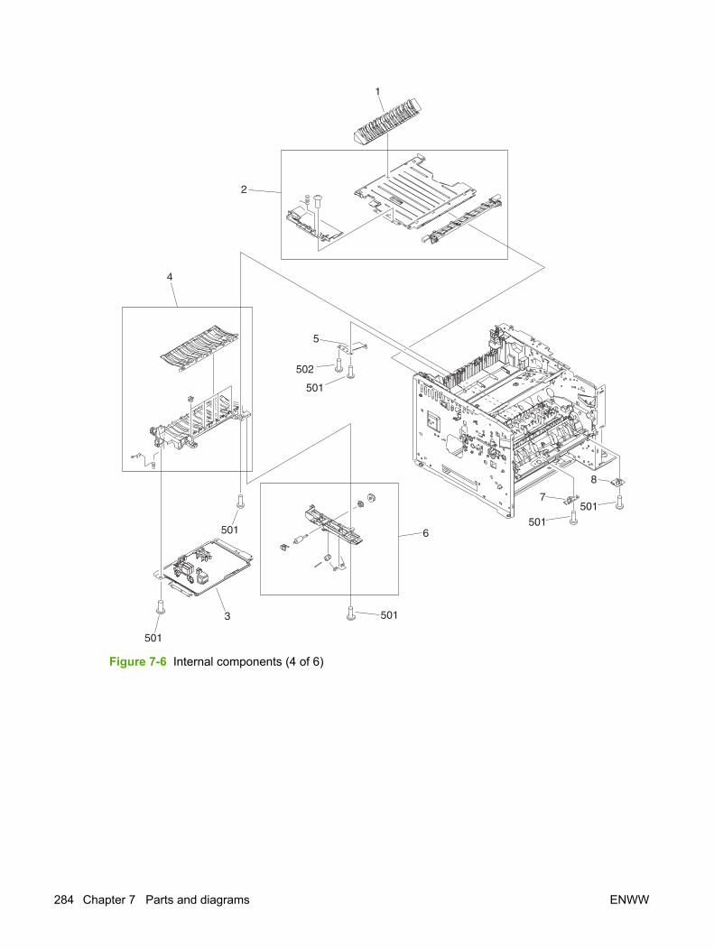
Figure 7-6 Internal components (4 of 6)
284 Chapter 7 Parts and diagrams ENWW

Table 7-7 Internal components (4 of 6)
Ref Description Part number Qty
1 Guide, duplex inlet RC1-4096-000CN 1
2 Feed assembly, lower RM1-3759-000CN 1
3 Power supply RM1-3758-000CN 1
4 Feed guide assembly RM1-3760-000CN 1
5 Plate, grounding RC1-4085-000CN 1
6 Position guide assembly RM1-1506-000CN 1
7 Sensor PCA, top-of-page RM1-4040-000CN 1
8 Sensor PCA, width RM1-4042-000CN 1
501 Screw, tapping, truss head, M4x10 XB4-7401-005CN 6
502 Screw w/washer, M3x6 XB2-7300-605CN 1
ENWW Internal components 285

Figure 7-7 Internal components (5 of 6)
286 Chapter 7 Parts and diagrams ENWW

Table 7-8 Internal components (5 of 6)
Ref Description Part number Qty
1 Solenoid, tray 1 RK2-1490-000CN 1
2 Pick-up roller gear assembly RM1-3714-000CN 1
3 Roller stay assembly RM1-1485-000CN 1
4 Spring, torsion RU5-2386-000CN 1
5 Sensor PCA, multipurpose RM1-4041-000CN 1
6 Cover, face-up-sensor cable RC2-0739-000CN 1
7 Holder, cable RC2-0588-000CN 1
8 Holder, main fan RC2-0592-000CN 1
9 Static wire, right-side fan RC2-0593-000CN 1
10 Fan, right-side RK2-1497-000CN 1
11 Screw, D, M3x8 XA9-1671-000CN 15
12 Lever, sensor RC1-3939-000CN 1
13 Cable guide WT2-5694-000CN 2
14 Screw, tapping, M3x6 XA9-1503-000CN 15
15 Guide RC1-4083-000CN
16 Cable guide WT2-5678-000CN 1
17 Tray 2 pickup assembly (also see Tray 2 pickup assemblyon page 290)
RM1-3762-000CN 1
18 Fuser, 110-127 V RM1-3740-000CN 1
18 Fuser, 220-240 V RM1-3741-000CN 1
19 ECU, 110-127 V RM1-3774-000CN 1
19 ECU, 220-240 V RM1-3775-000CN 1
20 Gear assembly RM1-3712-000CN 1
501 Screw, tapping, truss head, M4x10 XB4-7401-005CN 10
502 Screw w/washer, M3x6 XB2-7300-605CN 1
ENWW Internal components 287

Figure 7-8 Internal components (6 of 6)
288 Chapter 7 Parts and diagrams ENWW

Table 7-9 Internal components (6 of 6)
Ref Description Part number Qty
1 Power switch RC2-0631-000CN 1
2 Holder, switch RC2-0632-000CN 1
3 Link, switch RC2-0633-000CN 1
4 Holder, switch link RC2-0634-000CN 1
5 Cable guide WT2-5678-000CN 4
6 Roller assembly, bottom plate RM1-3727-000CN 4
7 Holder, interlock RC2-0595-000CN 1
8 Microswitch RK2-0534-000CN 1
9 Cushion, right lower RC2-0468-000CN 1
10 Foot, rubber RA0-1003-000CN 2
11 Guide, cartridge, upper-right RC2-0492-000CN 1
12 Mount, solenoid RC2-0498-000CN 1
13 Guide, cassette, front-right RC2-0559-000CN 1
14 Guide, cassette, back-right RC2-0560-000CN 1
15 Guide, center plate, right RC2-0561-000CN 1
16 Holder, option connector RC1-0562-000CN 1
17 Guide, cartridge, lower-right RC2-0700-000CN 1
18 Stopper, cartridge, right RC2-0702-000CN 1
19 Connector, drawer VS1-7257-007CN 1
20 Cable guide WT2-5056-000CN 1
21 Screw, D, M3x8 XA9-1671-000CN 14
22 Bushing RC1-3665-000CN 1
23 Roller, face-down RC1-3994-000CN 4
24 Spring, torsion RC2-0665-000CN 4
25 Plate, face-up shield RC2-0697-000CN 1
26 Connector, snap-tight, black VS1-7177-004CN 1
27 Photo-interrupter WG8-5624-000CN 2
28 Roller assembly, face-down RM1-3749-000CN 1
29 Solenoid RK2-1492-000CN 1
30 Cable, option interface RM1-4062-000CN 1
31 Roller assembly, delivery RM1-1497-000CN 4
501 Screw, tapping, truss head, M4x10 XB4-7401-005CN 2
ENWW Internal components 289

Tray 2 pickup assembly
Figure 7-9 Tray 2 pickup assembly
290 Chapter 7 Parts and diagrams ENWW

Table 7-10 Tray 2 pickup assembly
Ref Description Part number Qty
Tray 2 pickup assembly RM1-3762-000CN 1
1 Pickup roller assembly, tray 2 RM1-3763-000CN 1
2 Sensor flag assembly, tray 2 RM1-3769-000CN 1
3 Cable, sensor, tray 2 RM1-4060-000CN 1
4 Pickup roller, tray 2 RL1-1370-000CN 1
5 Photo-interrupter, tray 2 WG8-5624-000CN 1
ENWW Tray 2 pickup assembly 291

Alphabetical parts listTable 7-11 Alphabetical parts list
Description Part number Table and page
ADF assembly CB414-67916 ADF/scanner assemblyon page 273
Arm, door RC1-4055-000CN Internal components (1 of 6)on page 277
Arm, pad RC1-3937-000CN Internal components (3 of 6)on page 283
Arm, width-sensor RC2-0575-000CN Internal components (3 of 6)on page 283
Bushing RC1-3665-000CN Internal components (6 of 6)on page 289
Bushing, inner RC2-0701-000CN Internal components (2 of 6)on page 281
Bushing, transfer, right RC1-0922-000CN Internal components (3 of 6)on page 283
Cable assembly RM1-4053-000CN Internal components (1 of 6)on page 277
Cable guide WT2-5694-000CN Internal components (5 of 6)on page 287
Cable guide WT2-5678-000CN Internal components (5 of 6)on page 287
Cable guide WT2-5678-000CN Internal components (6 of 6)on page 289
Cable guide WT2-5056-000CN Internal components (6 of 6)on page 289
Cable, delivery sensor RM1-4057-000CN Internal components (3 of 6)on page 283
Cable, memory tag RM1-4054-000CN Internal components (1 of 6)on page 277
Cable, option interface RM1-4062-000CN Internal components (6 of 6)on page 289
Cable, sensor, tray 2 RM1-4060-000CN Tray 2 pickup assemblyon page 291
Cam RC1-4114-000CN Internal components (2 of 6)on page 281
Cam, contact RC1-4137-020CN Internal components (1 of 6)on page 277
Cartridge door assembly RM1-3722-000CN Covers on page 275
Clip clamp, wire WT2-5694-000CN Internal components (1 of 6)on page 277
Clip, cable WT2-5812-000CN Internal components (1 of 6)on page 277
292 Chapter 7 Parts and diagrams ENWW

Description Part number Table and page
Clip, cable WT2-5056-000CN Internal components (1 of 6)on page 277
Connector, drawer VS1-7257-007CN Internal components (6 of 6)on page 289
Connector, snap-tight, black VS1-7177-003CN Internal components (1 of 6)on page 277
Connector, snap-tight, black VS1-7177-004CN Internal components (6 of 6)on page 289
Control panel CB414-60101 ADF/scanner assemblyon page 273
Cover (replaces the stapler door for devices without staplers) RC2-0727-000CN Covers on page 275
Cover, ADF CB414-67902 ADF/scanner assemblyon page 273
Cover, face-up-sensor cable RC2-0739-000CN Internal components (5 of 6)on page 287
Cover, fax RC2-0726-000CN Covers on page 275
Cover, fax internal (fax rail) RC2-0729-000CN Covers on page 275
Cover, gear RC2-0579-000CN Internal components (2 of 6)on page 281
Cover, I/O RC2-0612-000CN Covers on page 275
Cover, left RM1-3773-000CN Covers on page 275
Cover, legal RL1-1366-000CN Covers on page 275
Cover, main motor RC1-4108-000CN Internal components (2 of 6)on page 281
Cover, registration RC1-3936-020CN Internal components (3 of 6)on page 283
Cover, right front RL1-1723-000CN Covers on page 275
Cover, right lower RC2-0603-000CN Covers on page 275
Cover, right-side (DIMM cover) RC2-0722-000CN Covers on page 275
Cover, stapler RM1-3790-000CN Covers on page 275
Cushion, right lower RC2-0468-000CN Internal components (6 of 6)on page 289
Drive release assembly RM1-1522-000CN Internal components (2 of 6)on page 281
Duct, cartridge RC2-0590-000CN Internal components (2 of 6)on page 281
Duct, scanner RC1-4128-020CN Internal components (1 of 6)on page 277
E-ring XD2-1100-402CN Internal components (2 of 6)on page 281
Table 7-11 Alphabetical parts list (continued)
ENWW Alphabetical parts list 293

Description Part number Table and page
ECU, 110-127 V RM1-3774-000CN Internal components (5 of 6)on page 287
ECU, 220-240 V RM1-3775-000CN Internal components (5 of 6)on page 287
Eliminator, static charge RC1-4025-000CN Internal components (3 of 6)on page 283
Fan, left-side RK2-1499-000CN Internal components (1 of 6)on page 277
Fan, right-side RK2-1497-000CN Internal components (5 of 6)on page 287
Feed assembly, lower RM1-3759-000CN Internal components (4 of 6)on page 285
Feed guide assembly RM1-3760-000CN Internal components (4 of 6)on page 285
Film, fuser drive side plate RC2-0649-000CN Internal components (2 of 6)on page 281
Fixing drive side plate assembly RM1-3746-000CN Internal components (2 of 6)on page 281
Flag assembly, face-down RM1-3743-000CN Covers on page 275
Flag assembly, full detect RM1-3742-000CN Covers on page 275
Foot, rubber RA0-1003-000CN Internal components (1 of 6)on page 277
Foot, rubber RA0-1003-000CN Internal components (6 of 6)on page 289
Formatter Q7819-60001 Internal components (1 of 6)on page 277
Fuser, 110-127 V RM1-3740-000CN Internal components (5 of 6)on page 287
Fuser, 220-240 V RM1-3741-000CN Internal components (5 of 6)on page 287
Gear assembly RM1-3712-000CN Internal components (5 of 6)on page 287
Gear, 12T RU5-0394-000CN Internal components (2 of 6)on page 281
Gear, 12T RU5-0400-000CN Internal components (3 of 6)on page 283
Gear, 14T RU5-0409-000CN Internal components (3 of 6)on page 283
Gear, 16T RU5-0951-000CN Internal components (2 of 6)on page 281
Gear, 17T RA0-1172-000CN Internal components (3 of 6)on page 283
Gear, 17T/17T RU5-0958-000CN Internal components (2 of 6)on page 281
Table 7-11 Alphabetical parts list (continued)
294 Chapter 7 Parts and diagrams ENWW

Description Part number Table and page
Gear, 19T RU5-0959-000CN Internal components (2 of 6)on page 281
Gear, 201t RU5-0950-000CN Internal components (2 of 6)on page 281
Gear, 20T RU5-0957-000CN Internal components (2 of 6)on page 281
Gear, 20T/20T RU5-0956-000CN Internal components (2 of 6)on page 281
Gear, 30T RU5-0366-000CN Internal components (3 of 6)on page 283
Gear, 31T RU5-0960-000CN Internal components (2 of 6)on page 281
Gear, 43T RU5-0955-000CN Internal components (2 of 6)on page 281
Gear, 65T RU5-0962-000CN Internal components (2 of 6)on page 281
Guide RC1-4083-000CN Internal components (5 of 6)on page 287
Guide, air RC2-0648-000CN Internal components (2 of 6)on page 281
Guide, cartridge, left lower RC2-0704-000CN Internal components (1 of 6)on page 277
Guide, cartridge, left upper RC2-0703-000CN Internal components (1 of 6)on page 277
Guide, cartridge, lower-right RC2-0700-000CN Internal components (6 of 6)on page 289
Guide, cartridge, upper-right RC2-0492-000CN Internal components (6 of 6)on page 289
Guide, cassette, back-right RC2-0560-000CN Internal components (6 of 6)on page 289
Guide, cassette, front-right RC2-0559-000CN Internal components (6 of 6)on page 289
Guide, cassette, left front RC2-0565-000CN Internal components (1 of 6)on page 277
Guide, cassette, left rear RC2-0566-000CN Internal components (1 of 6)on page 277
Guide, center plate, left RC2-0567-000CN Internal components (1 of 6)on page 277
Guide, center plate, right RC2-0561-000CN Internal components (6 of 6)on page 289
Guide, door arm RC1-4056-000CN Internal components (1 of 6)on page 277
Guide, duplex inlet RC1-4096-000CN Internal components (4 of 6)on page 285
Table 7-11 Alphabetical parts list (continued)
ENWW Alphabetical parts list 295
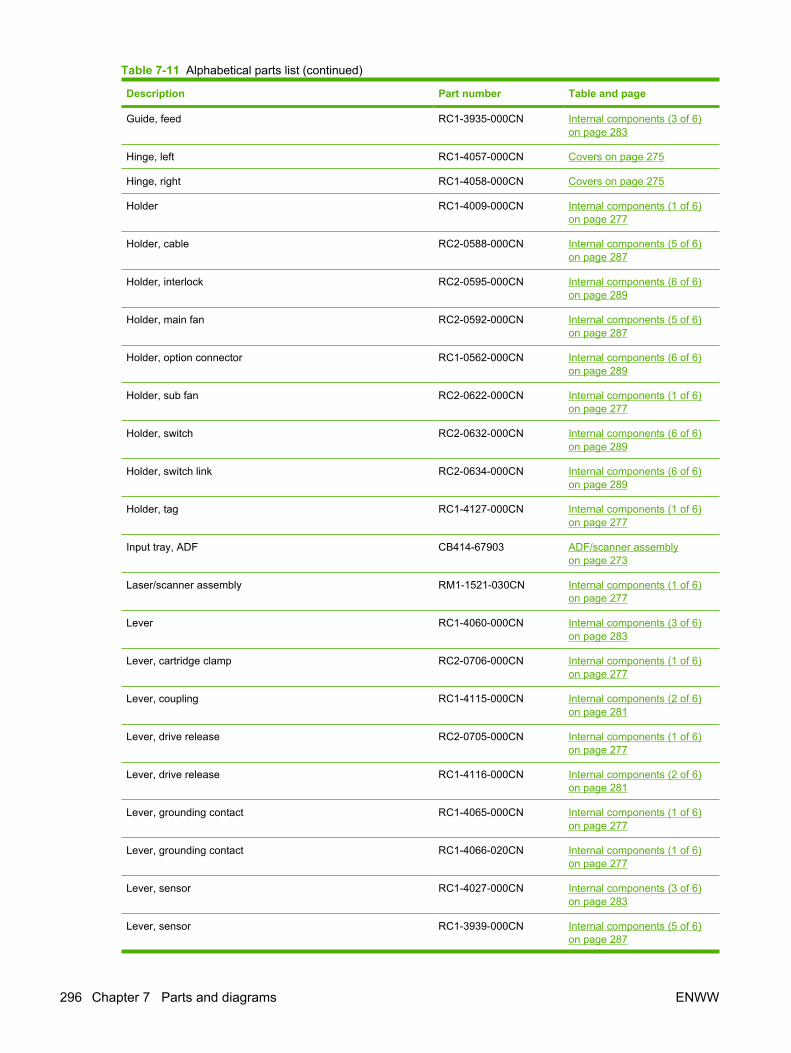
Description Part number Table and page
Guide, feed RC1-3935-000CN Internal components (3 of 6)on page 283
Hinge, left RC1-4057-000CN Covers on page 275
Hinge, right RC1-4058-000CN Covers on page 275
Holder RC1-4009-000CN Internal components (1 of 6)on page 277
Holder, cable RC2-0588-000CN Internal components (5 of 6)on page 287
Holder, interlock RC2-0595-000CN Internal components (6 of 6)on page 289
Holder, main fan RC2-0592-000CN Internal components (5 of 6)on page 287
Holder, option connector RC1-0562-000CN Internal components (6 of 6)on page 289
Holder, sub fan RC2-0622-000CN Internal components (1 of 6)on page 277
Holder, switch RC2-0632-000CN Internal components (6 of 6)on page 289
Holder, switch link RC2-0634-000CN Internal components (6 of 6)on page 289
Holder, tag RC1-4127-000CN Internal components (1 of 6)on page 277
Input tray, ADF CB414-67903 ADF/scanner assemblyon page 273
Laser/scanner assembly RM1-1521-030CN Internal components (1 of 6)on page 277
Lever RC1-4060-000CN Internal components (3 of 6)on page 283
Lever, cartridge clamp RC2-0706-000CN Internal components (1 of 6)on page 277
Lever, coupling RC1-4115-000CN Internal components (2 of 6)on page 281
Lever, drive release RC2-0705-000CN Internal components (1 of 6)on page 277
Lever, drive release RC1-4116-000CN Internal components (2 of 6)on page 281
Lever, grounding contact RC1-4065-000CN Internal components (1 of 6)on page 277
Lever, grounding contact RC1-4066-020CN Internal components (1 of 6)on page 277
Lever, sensor RC1-4027-000CN Internal components (3 of 6)on page 283
Lever, sensor RC1-3939-000CN Internal components (5 of 6)on page 287
Table 7-11 Alphabetical parts list (continued)
296 Chapter 7 Parts and diagrams ENWW

Description Part number Table and page
Link, drive release RC1-4117-000CN Internal components (2 of 6)on page 281
Link, laser shutter RC1-4125-000CN Internal components (1 of 6)on page 277
Link, switch RC2-0633-000CN Internal components (6 of 6)on page 289
Microswitch RK2-0534-000CN Internal components (6 of 6)on page 289
Motor, dc, 26.2 W RK2-1488-000CN Internal components (2 of 6)on page 281
Motor, stepping RK2-1489-000CN Internal components (2 of 6)on page 281
Mount, solenoid RC2-0498-000CN Internal components (6 of 6)on page 289
Pad, separation RC1-0939-000CN Internal components (3 of 6)on page 283
Paper clip tray RC2-0724-000CN Covers on page 275
Pendulum assembly RM1-3748-000CN Internal components (2 of 6)on page 281
Photo-interrupter WG8-5624-000CN Internal components (6 of 6)on page 289
Photo-interrupter, tray 2 WG8-5624-000CN Tray 2 pickup assemblyon page 291
Pick-up roller gear assembly RM1-3714-000CN Internal components (5 of 6)on page 287
Pickup roller assembly, tray 2 RM1-3763-000CN Tray 2 pickup assemblyon page 291
Pickup roller, tray 2 RL1-1370-000CN Tray 2 pickup assemblyon page 291
Plate, face-up shield RC2-0697-000CN Internal components (6 of 6)on page 289
Plate, fan shield, left RC2-0623-000CN Internal components (1 of 6)on page 277
Plate, grounding RC1-4085-000CN Internal components (4 of 6)on page 285
Plate, I/O RC2-0736-000CN Internal components (1 of 6)on page 277
Plate, protective RC1-4136-000CN Internal components (1 of 6)on page 277
Position guide assembly RM1-1506-000CN Internal components (4 of 6)on page 285
Power supply RM1-3758-000CN Internal components (4 of 6)on page 285
Table 7-11 Alphabetical parts list (continued)
ENWW Alphabetical parts list 297

Description Part number Table and page
Power switch RC2-0631-000CN Internal components (6 of 6)on page 289
Power-supply, stapler Q7429-69501 Internal components (1 of 6)on page 277
Rear cover assembly RM1-3724-000CN Covers on page 275
Registration assembly RM1-3715-000CN Internal components (3 of 6)on page 283
Roller assembly, bottom plate RM1-3727-000CN Internal components (6 of 6)on page 289
Roller assembly, delivery RM1-1497-000CN Internal components (6 of 6)on page 289
Roller assembly, face-down RM1-3749-000CN Internal components (6 of 6)on page 289
Roller stay assembly RM1-1485-000CN Internal components (5 of 6)on page 287
Roller, face-down RC1-3994-000CN Internal components (6 of 6)on page 289
Roller, tray 1 pick-up RL1-0568-000CN Internal components (3 of 6)on page 283
Scanner assembly (ADF assembly is not included) CB414-67905 ADF/scanner assemblyon page 273
Screw w/washer, M3x6 XB2-7300-605CN Internal components (4 of 6)on page 285
Screw w/washer, M3x6 XB2-7300-605CN Internal components (5 of 6)on page 287
Screw, D, M3x8 XA9-1671-000CN Internal components (1 of 6)on page 277
Screw, D, M3x8 XA9-1671-000CN Internal components (2 of 6)on page 281
Screw, D, M3x8 XA9-1671-000CN Internal components (3 of 6)on page 283
Screw, D, M3x8 XA9-1671-000CN Internal components (5 of 6)on page 287
Screw, D, M3x8 XA9-1671-000CN Internal components (6 of 6)on page 289
Screw, RS, M3x8 XA9-1500-000CN Internal components (2 of 6)on page 281
Screw, tapping, M3x6 XA9-1503-000CN Internal components (5 of 6)on page 287
Screw, tapping, truss head, M4x10 XB4-7401-005CN Internal components (3 of 6)on page 283
Screw, tapping, truss head, M4x10 XB4-7401-005CN Internal components (4 of 6)on page 285
Table 7-11 Alphabetical parts list (continued)
298 Chapter 7 Parts and diagrams ENWW

Description Part number Table and page
Screw, tapping, truss head, M4x10 XB4-7401-005CN Internal components (5 of 6)on page 287
Screw, tapping, truss head, M4x10 XB4-7401-005CN Internal components (6 of 6)on page 289
Sensor flag assembly, tray 2 RM1-3769-000CN Tray 2 pickup assemblyon page 291
Sensor PCA, multipurpose RM1-4041-000CN Internal components (5 of 6)on page 287
Sensor PCA, top-of-page RM1-4040-000CN Internal components (4 of 6)on page 285
Sensor PCA, width RM1-4042-000CN Internal components (4 of 6)on page 285
Sheet, static charge RC1-4069-000CN Internal components (3 of 6)on page 283
Sheet, static charge RC1-4070-000CN Internal components (3 of 6)on page 283
Solenoid RK2-1492-000CN Internal components (6 of 6)on page 289
Solenoid, tray 1 RK2-1490-000CN Internal components (5 of 6)on page 287
Spring compression RC2-0483-000CN Internal components (3 of 6)on page 283
Spring, compression RU5-2404-000CN Internal components (1 of 6)on page 277
Spring, compression RU5-2405-000CN Internal components (1 of 6)on page 277
Spring, compression RC1-4140-000CN Internal components (1 of 6)on page 277
Spring, compression RU5-2401-000CN Internal components (2 of 6)on page 281
Spring, compression RU5-2920-000CN Internal components (2 of 6)on page 281
Spring, compression RU5-2408-000CN Internal components (3 of 6)on page 283
Spring, compression RU5-2385-000CN Internal components (3 of 6)on page 283
Spring, leaf RC1-4067-000CN Internal components (1 of 6)on page 277
Spring, tension RU5-2388-000CN Covers on page 275
Spring, tension RU5-2407-000CN Internal components (1 of 6)on page 277
Spring, tension RU5-2403-000CN Internal components (1 of 6)on page 277
Table 7-11 Alphabetical parts list (continued)
ENWW Alphabetical parts list 299

Description Part number Table and page
Spring, torsion RU5-2410-020CN Internal components (1 of 6)on page 277
Spring, torsion RC1-4028-000CN Internal components (3 of 6)on page 283
Spring, torsion RC1-4059-000CN Internal components (3 of 6)on page 283
Spring, torsion RC1-4061-000CN Internal components (3 of 6)on page 283
Spring, torsion RC2-0576-000CN Internal components (3 of 6)on page 283
Spring, torsion RU5-2386-000CN Internal components (5 of 6)on page 287
Spring, torsion RC2-0665-000CN Internal components (6 of 6)on page 289
Stapler CB414-60147 Internal components (1 of 6)on page 277
Stapler door (for devices with staplers) CB414-40064 Covers on page 275
Static wire, right-side fan RC2-0593-000CN Internal components (5 of 6)on page 287
Stay, tag holder RC1-4126-000CN Internal components (1 of 6)on page 277
Stopper, cartridge, left RC2-0707-000CN Internal components (1 of 6)on page 277
Stopper, cartridge, right RC2-0702-000CN Internal components (6 of 6)on page 289
Stopper, feed guide, left RC2-0585-000CN Internal components (1 of 6)on page 277
Stopper, fuser RC2-0657-000CN Internal components (2 of 6)on page 281
Stopper, gear RC1-4189-000CN Internal components (3 of 6)on page 283
Top cover assembly RM1-3772-000CN Covers on page 275
Transfer guide assembly, lower RM1-3757-000CN Internal components (3 of 6)on page 283
Transfer roller assembly RM1-1508-000CN Internal components (3 of 6)on page 283
Tray, staple RC2-0725-000CN Internal components (1 of 6)on page 277
Tray 1 assembly RM1-1490-000CN Covers on page 275
Tray 1 cover assembly RM1-3723-000CN Covers on page 275
Tray 1 pickup roller assembly RM1-3716-000CN Internal components (3 of 6)on page 283
Table 7-11 Alphabetical parts list (continued)
300 Chapter 7 Parts and diagrams ENWW

Description Part number Table and page
Tray 2 pickup assembly RM1-3762-000CN Tray 2 pickup assemblyon page 291
Tray 2 pickup assembly (also see Tray 2 pickup assemblyon page 290)
RM1-3762-000CN Internal components (5 of 6)on page 287
Washer RC2-0652-000CN Internal components (2 of 6)on page 281
Table 7-11 Alphabetical parts list (continued)
ENWW Alphabetical parts list 301

Numerical parts listTable 7-12 Numerical parts list
Part number Description Table and page
CB414-40064 Stapler door (for devices with staplers) Covers on page 275
CB414-60101 Control panel ADF/scanner assemblyon page 273
CB414-60147 Stapler Internal components (1 of 6)on page 277
CB414-67902 Cover, ADF ADF/scanner assemblyon page 273
CB414-67903 Input tray, ADF ADF/scanner assemblyon page 273
CB414-67905 Scanner assembly (ADF assembly is not included) ADF/scanner assemblyon page 273
CB414-67916 ADF assembly ADF/scanner assemblyon page 273
Q7429-69501 Power-supply, stapler Internal components (1 of 6)on page 277
Q7819-60001 Formatter Internal components (1 of 6)on page 277
RA0-1003-000CN Foot, rubber Internal components (1 of 6)on page 277
RA0-1003-000CN Foot, rubber Internal components (6 of 6)on page 289
RA0-1172-000CN Gear, 17T Internal components (3 of 6)on page 283
RC1-0562-000CN Holder, option connector Internal components (6 of 6)on page 289
RC1-0922-000CN Bushing, transfer, right Internal components (3 of 6)on page 283
RC1-0939-000CN Pad, separation Internal components (3 of 6)on page 283
RC1-3665-000CN Bushing Internal components (6 of 6)on page 289
RC1-3935-000CN Guide, feed Internal components (3 of 6)on page 283
RC1-3936-020CN Cover, registration Internal components (3 of 6)on page 283
RC1-3937-000CN Arm, pad Internal components (3 of 6)on page 283
RC1-3939-000CN Lever, sensor Internal components (5 of 6)on page 287
RC1-3994-000CN Roller, face-down Internal components (6 of 6)on page 289
302 Chapter 7 Parts and diagrams ENWW

Part number Description Table and page
RC1-4009-000CN Holder Internal components (1 of 6)on page 277
RC1-4025-000CN Eliminator, static charge Internal components (3 of 6)on page 283
RC1-4027-000CN Lever, sensor Internal components (3 of 6)on page 283
RC1-4028-000CN Spring, torsion Internal components (3 of 6)on page 283
RC1-4055-000CN Arm, door Internal components (1 of 6)on page 277
RC1-4056-000CN Guide, door arm Internal components (1 of 6)on page 277
RC1-4057-000CN Hinge, left Covers on page 275
RC1-4058-000CN Hinge, right Covers on page 275
RC1-4059-000CN Spring, torsion Internal components (3 of 6)on page 283
RC1-4060-000CN Lever Internal components (3 of 6)on page 283
RC1-4061-000CN Spring, torsion Internal components (3 of 6)on page 283
RC1-4065-000CN Lever, grounding contact Internal components (1 of 6)on page 277
RC1-4066-020CN Lever, grounding contact Internal components (1 of 6)on page 277
RC1-4067-000CN Spring, leaf Internal components (1 of 6)on page 277
RC1-4069-000CN Sheet, static charge Internal components (3 of 6)on page 283
RC1-4070-000CN Sheet, static charge Internal components (3 of 6)on page 283
RC1-4083-000CN Guide Internal components (5 of 6)on page 287
RC1-4085-000CN Plate, grounding Internal components (4 of 6)on page 285
RC1-4096-000CN Guide, duplex inlet Internal components (4 of 6)on page 285
RC1-4108-000CN Cover, main motor Internal components (2 of 6)on page 281
RC1-4114-000CN Cam Internal components (2 of 6)on page 281
RC1-4115-000CN Lever, coupling Internal components (2 of 6)on page 281
RC1-4116-000CN Lever, drive release Internal components (2 of 6)on page 281
Table 7-12 Numerical parts list (continued)
ENWW Numerical parts list 303

Part number Description Table and page
RC1-4117-000CN Link, drive release Internal components (2 of 6)on page 281
RC1-4125-000CN Link, laser shutter Internal components (1 of 6)on page 277
RC1-4126-000CN Stay, tag holder Internal components (1 of 6)on page 277
RC1-4127-000CN Holder, tag Internal components (1 of 6)on page 277
RC1-4128-020CN Duct, scanner Internal components (1 of 6)on page 277
RC1-4136-000CN Plate, protective Internal components (1 of 6)on page 277
RC1-4137-020CN Cam, contact Internal components (1 of 6)on page 277
RC1-4140-000CN Spring, compression Internal components (1 of 6)on page 277
RC1-4189-000CN Stopper, gear Internal components (3 of 6)on page 283
RC2-0468-000CN Cushion, right lower Internal components (6 of 6)on page 289
RC2-0483-000CN Spring compression Internal components (3 of 6)on page 283
RC2-0492-000CN Guide, cartridge, upper-right Internal components (6 of 6)on page 289
RC2-0498-000CN Mount, solenoid Internal components (6 of 6)on page 289
RC2-0559-000CN Guide, cassette, front-right Internal components (6 of 6)on page 289
RC2-0560-000CN Guide, cassette, back-right Internal components (6 of 6)on page 289
RC2-0561-000CN Guide, center plate, right Internal components (6 of 6)on page 289
RC2-0565-000CN Guide, cassette, left front Internal components (1 of 6)on page 277
RC2-0566-000CN Guide, cassette, left rear Internal components (1 of 6)on page 277
RC2-0567-000CN Guide, center plate, left Internal components (1 of 6)on page 277
RC2-0575-000CN Arm, width-sensor Internal components (3 of 6)on page 283
RC2-0576-000CN Spring, torsion Internal components (3 of 6)on page 283
RC2-0579-000CN Cover, gear Internal components (2 of 6)on page 281
Table 7-12 Numerical parts list (continued)
304 Chapter 7 Parts and diagrams ENWW

Part number Description Table and page
RC2-0585-000CN Stopper, feed guide, left Internal components (1 of 6)on page 277
RC2-0588-000CN Holder, cable Internal components (5 of 6)on page 287
RC2-0590-000CN Duct, cartridge Internal components (2 of 6)on page 281
RC2-0592-000CN Holder, main fan Internal components (5 of 6)on page 287
RC2-0593-000CN Static wire, right-side fan Internal components (5 of 6)on page 287
RC2-0595-000CN Holder, interlock Internal components (6 of 6)on page 289
RC2-0603-000CN Cover, right lower Covers on page 275
RC2-0612-000CN Cover, I/O Covers on page 275
RC2-0622-000CN Holder, sub fan Internal components (1 of 6)on page 277
RC2-0623-000CN Plate, fan shield, left Internal components (1 of 6)on page 277
RC2-0631-000CN Power switch Internal components (6 of 6)on page 289
RC2-0632-000CN Holder, switch Internal components (6 of 6)on page 289
RC2-0633-000CN Link, switch Internal components (6 of 6)on page 289
RC2-0634-000CN Holder, switch link Internal components (6 of 6)on page 289
RC2-0648-000CN Guide, air Internal components (2 of 6)on page 281
RC2-0649-000CN Film, fuser drive side plate Internal components (2 of 6)on page 281
RC2-0652-000CN Washer Internal components (2 of 6)on page 281
RC2-0657-000CN Stopper, fuser Internal components (2 of 6)on page 281
RC2-0665-000CN Spring, torsion Internal components (6 of 6)on page 289
RC2-0697-000CN Plate, face-up shield Internal components (6 of 6)on page 289
RC2-0700-000CN Guide, cartridge, lower-right Internal components (6 of 6)on page 289
RC2-0701-000CN Bushing, inner Internal components (2 of 6)on page 281
RC2-0702-000CN Stopper, cartridge, right Internal components (6 of 6)on page 289
Table 7-12 Numerical parts list (continued)
ENWW Numerical parts list 305

Part number Description Table and page
RC2-0703-000CN Guide, cartridge, left upper Internal components (1 of 6)on page 277
RC2-0704-000CN Guide, cartridge, left lower Internal components (1 of 6)on page 277
RC2-0705-000CN Lever, drive release Internal components (1 of 6)on page 277
RC2-0706-000CN Lever, cartridge clamp Internal components (1 of 6)on page 277
RC2-0707-000CN Stopper, cartridge, left Internal components (1 of 6)on page 277
RC2-0722-000CN Cover, right-side (DIMM cover) Covers on page 275
RC2-0724-000CN Paper clip tray Covers on page 275
RC2-0725-000CN Tray, staple Internal components (1 of 6)on page 277
RC2-0726-000CN Cover, fax Covers on page 275
RC2-0727-000CN Cover (replaces the stapler door for devices without staplers) Covers on page 275
RC2-0729-000CN Cover, fax internal (fax rail) Covers on page 275
RC2-0736-000CN Plate, I/O Internal components (1 of 6)on page 277
RC2-0739-000CN Cover, face-up-sensor cable Internal components (5 of 6)on page 287
RK2-0534-000CN Microswitch Internal components (6 of 6)on page 289
RK2-1488-000CN Motor, dc, 26.2 W Internal components (2 of 6)on page 281
RK2-1489-000CN Motor, stepping Internal components (2 of 6)on page 281
RK2-1490-000CN Solenoid, tray 1 Internal components (5 of 6)on page 287
RK2-1492-000CN Solenoid Internal components (6 of 6)on page 289
RK2-1497-000CN Fan, right-side Internal components (5 of 6)on page 287
RK2-1499-000CN Fan, left-side Internal components (1 of 6)on page 277
RL1-0568-000CN Roller, tray 1 pick-up Internal components (3 of 6)on page 283
RL1-1366-000CN Cover, legal Covers on page 275
RL1-1370-000CN Pickup roller, tray 2 Tray 2 pickup assemblyon page 291
RL1-1723-000CN Cover, right front Covers on page 275
Table 7-12 Numerical parts list (continued)
306 Chapter 7 Parts and diagrams ENWW

Part number Description Table and page
RM1-1485-000CN Roller stay assembly Internal components (5 of 6)on page 287
RM1-1490-000CN Tray 1 assembly Covers on page 275
RM1-1497-000CN Roller assembly, delivery Internal components (6 of 6)on page 289
RM1-1506-000CN Position guide assembly Internal components (4 of 6)on page 285
RM1-1508-000CN Transfer roller assembly Internal components (3 of 6)on page 283
RM1-1521-030CN Laser/scanner assembly Internal components (1 of 6)on page 277
RM1-1522-000CN Drive release assembly Internal components (2 of 6)on page 281
RM1-3712-000CN Gear assembly Internal components (5 of 6)on page 287
RM1-3714-000CN Pick-up roller gear assembly Internal components (5 of 6)on page 287
RM1-3715-000CN Registration assembly Internal components (3 of 6)on page 283
RM1-3716-000CN Tray 1 pickup roller assembly Internal components (3 of 6)on page 283
RM1-3722-000CN Cartridge door assembly Covers on page 275
RM1-3723-000CN Tray 1 cover assembly Covers on page 275
RM1-3724-000CN Rear cover assembly Covers on page 275
RM1-3727-000CN Roller assembly, bottom plate Internal components (6 of 6)on page 289
RM1-3740-000CN Fuser, 110-127 V Internal components (5 of 6)on page 287
RM1-3741-000CN Fuser, 220-240 V Internal components (5 of 6)on page 287
RM1-3742-000CN Flag assembly, full detect Covers on page 275
RM1-3743-000CN Flag assembly, face-down Covers on page 275
RM1-3746-000CN Fixing drive side plate assembly Internal components (2 of 6)on page 281
RM1-3748-000CN Pendulum assembly Internal components (2 of 6)on page 281
RM1-3749-000CN Roller assembly, face-down Internal components (6 of 6)on page 289
RM1-3757-000CN Transfer guide assembly, lower Internal components (3 of 6)on page 283
RM1-3758-000CN Power supply Internal components (4 of 6)on page 285
Table 7-12 Numerical parts list (continued)
ENWW Numerical parts list 307
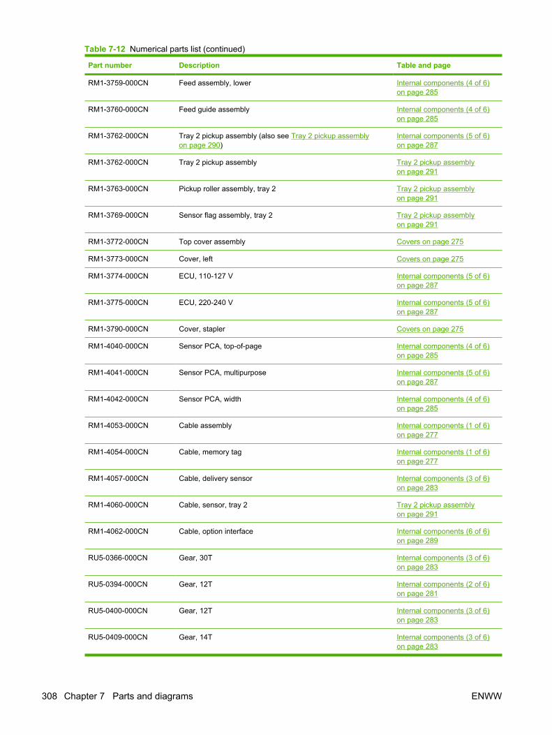
Part number Description Table and page
RM1-3759-000CN Feed assembly, lower Internal components (4 of 6)on page 285
RM1-3760-000CN Feed guide assembly Internal components (4 of 6)on page 285
RM1-3762-000CN Tray 2 pickup assembly (also see Tray 2 pickup assemblyon page 290)
Internal components (5 of 6)on page 287
RM1-3762-000CN Tray 2 pickup assembly Tray 2 pickup assemblyon page 291
RM1-3763-000CN Pickup roller assembly, tray 2 Tray 2 pickup assemblyon page 291
RM1-3769-000CN Sensor flag assembly, tray 2 Tray 2 pickup assemblyon page 291
RM1-3772-000CN Top cover assembly Covers on page 275
RM1-3773-000CN Cover, left Covers on page 275
RM1-3774-000CN ECU, 110-127 V Internal components (5 of 6)on page 287
RM1-3775-000CN ECU, 220-240 V Internal components (5 of 6)on page 287
RM1-3790-000CN Cover, stapler Covers on page 275
RM1-4040-000CN Sensor PCA, top-of-page Internal components (4 of 6)on page 285
RM1-4041-000CN Sensor PCA, multipurpose Internal components (5 of 6)on page 287
RM1-4042-000CN Sensor PCA, width Internal components (4 of 6)on page 285
RM1-4053-000CN Cable assembly Internal components (1 of 6)on page 277
RM1-4054-000CN Cable, memory tag Internal components (1 of 6)on page 277
RM1-4057-000CN Cable, delivery sensor Internal components (3 of 6)on page 283
RM1-4060-000CN Cable, sensor, tray 2 Tray 2 pickup assemblyon page 291
RM1-4062-000CN Cable, option interface Internal components (6 of 6)on page 289
RU5-0366-000CN Gear, 30T Internal components (3 of 6)on page 283
RU5-0394-000CN Gear, 12T Internal components (2 of 6)on page 281
RU5-0400-000CN Gear, 12T Internal components (3 of 6)on page 283
RU5-0409-000CN Gear, 14T Internal components (3 of 6)on page 283
Table 7-12 Numerical parts list (continued)
308 Chapter 7 Parts and diagrams ENWW

Part number Description Table and page
RU5-0950-000CN Gear, 201t Internal components (2 of 6)on page 281
RU5-0951-000CN Gear, 16T Internal components (2 of 6)on page 281
RU5-0955-000CN Gear, 43T Internal components (2 of 6)on page 281
RU5-0956-000CN Gear, 20T/20T Internal components (2 of 6)on page 281
RU5-0957-000CN Gear, 20T Internal components (2 of 6)on page 281
RU5-0958-000CN Gear, 17T/17T Internal components (2 of 6)on page 281
RU5-0959-000CN Gear, 19T Internal components (2 of 6)on page 281
RU5-0960-000CN Gear, 31T Internal components (2 of 6)on page 281
RU5-0962-000CN Gear, 65T Internal components (2 of 6)on page 281
RU5-2385-000CN Spring, compression Internal components (3 of 6)on page 283
RU5-2386-000CN Spring, torsion Internal components (5 of 6)on page 287
RU5-2388-000CN Spring, tension Covers on page 275
RU5-2401-000CN Spring, compression Internal components (2 of 6)on page 281
RU5-2403-000CN Spring, tension Internal components (1 of 6)on page 277
RU5-2404-000CN Spring, compression Internal components (1 of 6)on page 277
RU5-2405-000CN Spring, compression Internal components (1 of 6)on page 277
RU5-2407-000CN Spring, tension Internal components (1 of 6)on page 277
RU5-2408-000CN Spring, compression Internal components (3 of 6)on page 283
RU5-2410-020CN Spring, torsion Internal components (1 of 6)on page 277
RU5-2920-000CN Spring, compression Internal components (2 of 6)on page 281
VS1-7177-003CN Connector, snap-tight, black Internal components (1 of 6)on page 277
VS1-7177-004CN Connector, snap-tight, black Internal components (6 of 6)on page 289
Table 7-12 Numerical parts list (continued)
ENWW Numerical parts list 309

Part number Description Table and page
VS1-7257-007CN Connector, drawer Internal components (6 of 6)on page 289
WG8-5624-000CN Photo-interrupter Internal components (6 of 6)on page 289
WG8-5624-000CN Photo-interrupter, tray 2 Tray 2 pickup assemblyon page 291
WT2-5056-000CN Clip, cable Internal components (1 of 6)on page 277
WT2-5056-000CN Cable guide Internal components (6 of 6)on page 289
WT2-5678-000CN Cable guide Internal components (5 of 6)on page 287
WT2-5678-000CN Cable guide Internal components (6 of 6)on page 289
WT2-5694-000CN Clip clamp, wire Internal components (1 of 6)on page 277
WT2-5694-000CN Cable guide Internal components (5 of 6)on page 287
WT2-5812-000CN Clip, cable Internal components (1 of 6)on page 277
XA9-1500-000CN Screw, RS, M3x8 Internal components (2 of 6)on page 281
XA9-1503-000CN Screw, tapping, M3x6 Internal components (5 of 6)on page 287
XA9-1671-000CN Screw, D, M3x8 Internal components (1 of 6)on page 277
XA9-1671-000CN Screw, D, M3x8 Internal components (2 of 6)on page 281
XA9-1671-000CN Screw, D, M3x8 Internal components (3 of 6)on page 283
XA9-1671-000CN Screw, D, M3x8 Internal components (5 of 6)on page 287
XA9-1671-000CN Screw, D, M3x8 Internal components (6 of 6)on page 289
XB2-7300-605CN Screw w/washer, M3x6 Internal components (4 of 6)on page 285
XB2-7300-605CN Screw w/washer, M3x6 Internal components (5 of 6)on page 287
XB4-7401-005CN Screw, tapping, truss head, M4x10 Internal components (3 of 6)on page 283
XB4-7401-005CN Screw, tapping, truss head, M4x10 Internal components (4 of 6)on page 285
XB4-7401-005CN Screw, tapping, truss head, M4x10 Internal components (5 of 6)on page 287
Table 7-12 Numerical parts list (continued)
310 Chapter 7 Parts and diagrams ENWW

Part number Description Table and page
XB4-7401-005CN Screw, tapping, truss head, M4x10 Internal components (6 of 6)on page 289
XD2-1100-402CN E-ring Internal components (2 of 6)on page 281
Table 7-12 Numerical parts list (continued)
ENWW Numerical parts list 311

312 Chapter 7 Parts and diagrams ENWW

A Supplies and accessories
This section provides information about ordering parts, supplies, and accessories. Use only parts andaccessories that are specifically designed for this device.
● Order parts, accessories, and supplies
● Part numbers
ENWW 313

Order parts, accessories, and suppliesSeveral methods are available for ordering parts, supplies, and accessories:
● Order directly from HP
● Order through service or support providers
● Order directly through the embedded Web server (for printers that are connected to a network)
● Order directly through the HP Easy Printer Care software
Order directly from HPYou can obtain the following items directly from HP:
● Replacement parts: To order replacement parts in the U.S., go to http://www.hp.com/go/hpparts. Outside the United States, order parts by contacting your local authorized HP servicecenter.
● Supplies and accessories: To order supplies in the U.S., go to http://www.hp.com/go/ljsupplies.To order supplies worldwide, go to http://www.hp.com/ghp/buyonline.html. To order accessories,go to www.hp.com/support/LJM3027mfp or www.hp.com/support/LJM3035mfp.
Order through service or support providersTo order a part or accessory, contact an HP-authorized service or support provider.
Order directly through the embedded Web server (for printers that areconnected to a network)
Use the following steps to order printing supplies directly through the embedded Web server.
1. In the Web browser on the computer, type the IP address or host name of the device. The statuswindow opens.
2. In the Other links area, double-click Order Supplies. This provides a URL for a site from whichyou can purchase consumables.
3. Select the part numbers that you want to order, and follow the instructions on the screen.
Order directly through the HP Easy Printer Care softwareHP Easy Printer Care software is a printer management tool designed to make printer configuration,monitoring, supplies ordering, troubleshooting, and updating as simple and efficient as possible. Formore information about HP Easy Printer Care software, go to http://www.hp.com/go/easyprintercare.
314 Appendix A Supplies and accessories ENWW

Part numbersThe following list of accessories was current at the time of printing. Ordering information and availabilityof the accessories might change during the life of the device.
Paper-handling accessories
Item Description Part number
Optional 500-sheet tray and feeder unit(tray 3)
Optional tray to increase paper capacity.Holds Letter, A4, Legal, A5, B5 (JIS),Executive, and 8.5 x 13 paper sizes.
Q7817A
Print cartridge
Item Description Part number
HP LaserJet print cartridge 6,500-page cartridge Q7551A
13,000-page cartridge Q7551X
Memory
Item Description Part number
100-pin 133MHz DDR DIMM
Boosts the ability of the device to handlelarge or complex print jobs.
64 MB Q7715A
128 MB Q7718A
256 MB Q7719A
512 MB Q7720A
Cables and interfaces
Item Description Part number
Enhanced I/O (EIO) cards
HP Jetdirect print server multi-protocolEIO network cards:
HP Jetdirect 620n Fast Ethernet(10/100Base-TX) print server
J7934A
HP Jetdirect 625n Gigabit Ethernet(10/100Base-TX) print server
J7960A
HP Jetdirect 680n 802.11b wirelessinternal print server
J6058A
HP bt1300 Bluetooth wireless printeradapter
J6072A
HP Jetdirect 635n IPv6/IPsec printserver
HP Jetdirect 635n IPv6/IPsec printserver
J7961A
J7961A
USB cable 2-meter A to B cable C6518A
ENWW Part numbers 315

Stapler accessories
Item Description Part number
Staple cassette Cassette that contains 1,500 unformedstaples
Q7432A
Print mediaFor more information about media supplies, go to http://www.hp.com/go/ljsupplies.
Item Description Part number
HP Soft Gloss laser paper
For use with HP LaserJet devices. Thisis coated paper, good for businessdocuments with high impact, such asbrochures, sales material, anddocuments with graphics andphotographic images.
Specifications: 32 lb (120 g/m2).
Letter (220 x 280 mm), 50 sheets/box C4179A/Asia-Pacific countries/regions
A4 (210 x 297 mm), 50 sheets/box C4179B/Asia-Pacific countries/regionsand Europe
HP LaserJet tough paper
For use with HP LaserJet devices. Thissatin-finish paper is waterproof and tear-proof, yet doesn't compromise on printquality or performance. Use it for signs,maps, menus, and other businessapplications.
Letter (8.5 x 11 in), 50 sheets to a carton Q1298A/North America
A4 (210 x 297 mm), 50 sheets to a carton Q1298B/Asia-Pacific countries/regionsand Europe
HP Premium Choice LaserJet paper
HP's brightest LaserJet paper. Expectspectacular color and crisp black fromthis paper that is extra smooth andbrilliantly white. This is ideal forpresentations, business plans, externalcorrespondence and other high-valuedocuments
Specifications: 98 bright, 32 lb. (75 g/m2).
Letter (8.5 x 11 in), 500 sheets/ream, 10-ream carton
HPU1132/North America
Letter (8.5 x 11 in), 250 sheets/ream, 6-ream carton
HPU1732 North America
A4 (210 x 297 mm), 5-ream carton Q2397A/Asia-Pacific countries/regions
A4 (210 x 297 mm), 250 sheet/ream, 5-ream carton
CHP412/Europe
A4 (210 x 297 mm), 500 sheet/ream, 5-ream carton
CHP410/Europe
A4 (210 x 297 mm), 160 g/m2, 500 sheet/ream, 5-ream carton
CHP413/Europe
HP LaserJet paper
For use with HP LaserJet devices. Thisis good for letterhead, high-valuememos, legal documents, direct mail,and correspondence.
Specifications: 96 bright, 24 lb (90 g/m2).
Letter (8.5 x 11 in), 500 sheets/ream, 10-ream carton
HPJ1124/North America
Legal (8.5 x 14 in), 500 sheets/ream, 10-ream carton
HPJ1424/North America
Letter (220 x 280 mm), 500 sheets/ream,5-ream carton
Q2398A/Asia-Pacific countries/regions
A4 (210 x 297 mm), 500 sheets/ream, 5-ream carton
Q2400A/Asia-Pacific countries/regions
A4 (210 x 297 mm), 500 sheets/ream CHP310/Europe
316 Appendix A Supplies and accessories ENWW
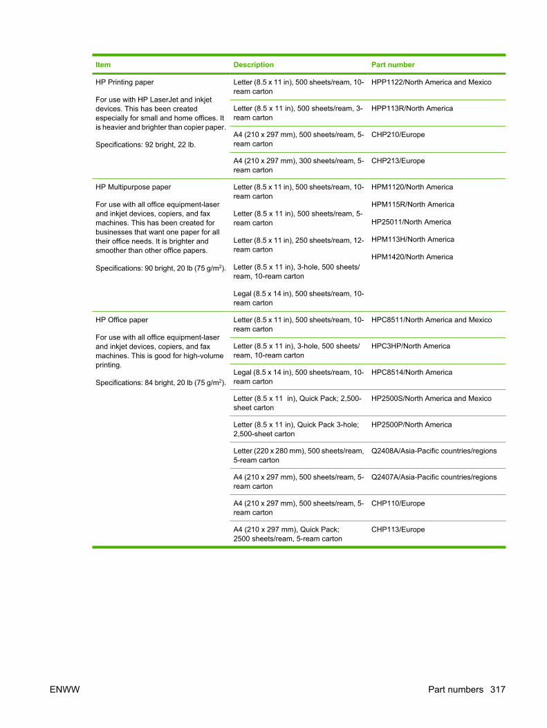
Item Description Part number
HP Printing paper
For use with HP LaserJet and inkjetdevices. This has been createdespecially for small and home offices. Itis heavier and brighter than copier paper.
Specifications: 92 bright, 22 lb.
Letter (8.5 x 11 in), 500 sheets/ream, 10-ream carton
HPP1122/North America and Mexico
Letter (8.5 x 11 in), 500 sheets/ream, 3-ream carton
HPP113R/North America
A4 (210 x 297 mm), 500 sheets/ream, 5-ream carton
CHP210/Europe
A4 (210 x 297 mm), 300 sheets/ream, 5-ream carton
CHP213/Europe
HP Multipurpose paper
For use with all office equipment-laserand inkjet devices, copiers, and faxmachines. This has been created forbusinesses that want one paper for alltheir office needs. It is brighter andsmoother than other office papers.
Specifications: 90 bright, 20 lb (75 g/m2).
Letter (8.5 x 11 in), 500 sheets/ream, 10-ream carton
Letter (8.5 x 11 in), 500 sheets/ream, 5-ream carton
Letter (8.5 x 11 in), 250 sheets/ream, 12-ream carton
Letter (8.5 x 11 in), 3-hole, 500 sheets/ream, 10-ream carton
Legal (8.5 x 14 in), 500 sheets/ream, 10-ream carton
HPM1120/North America
HPM115R/North America
HP25011/North America
HPM113H/North America
HPM1420/North America
HP Office paper
For use with all office equipment-laserand inkjet devices, copiers, and faxmachines. This is good for high-volumeprinting.
Specifications: 84 bright, 20 lb (75 g/m2).
Letter (8.5 x 11 in), 500 sheets/ream, 10-ream carton
HPC8511/North America and Mexico
Letter (8.5 x 11 in), 3-hole, 500 sheets/ream, 10-ream carton
HPC3HP/North America
Legal (8.5 x 14 in), 500 sheets/ream, 10-ream carton
HPC8514/North America
Letter (8.5 x 11 in), Quick Pack; 2,500-sheet carton
HP2500S/North America and Mexico
Letter (8.5 x 11 in), Quick Pack 3-hole;2,500-sheet carton
HP2500P/North America
Letter (220 x 280 mm), 500 sheets/ream,5-ream carton
Q2408A/Asia-Pacific countries/regions
A4 (210 x 297 mm), 500 sheets/ream, 5-ream carton
Q2407A/Asia-Pacific countries/regions
A4 (210 x 297 mm), 500 sheets/ream, 5-ream carton
CHP110/Europe
A4 (210 x 297 mm), Quick Pack;2500 sheets/ream, 5-ream carton
CHP113/Europe
ENWW Part numbers 317

Item Description Part number
HP Office recycled paper
For use with all office equipment-laserand inkjet printers, copiers, and faxmachines. This is good for high-volumeprinting.
Satisfies U.S. Executive Order 13101 forenvironmentally preferable products.
Specifications: 84 bright, 20 lb, 30%post-consumer content.
Letter (8.5 x 11 in), 500 sheets/ream, 10-ream carton
HPE1120/North America
Letter (8.5 x 11 in), 3-hole, 500 sheets/ream, 10-ream carton
HPE113H/North America
Legal (8.5 x 14 in), 500 sheets/ream, 10-ream carton
HPE1420/North America
HP LaserJet transparencies
For use only with HP LaserJetmonochrome printers. For crisp, sharptext and graphics, rely on the onlytransparencies specifically designed andtested to work with monochromeHP LaserJet printers.
Specifications: 4.3-mil thickness.
Letter (8.5 x 11 in), 50 sheets to a carton 92296T/North America, Asia-Pacificcountries/regions, and Europe
A4 (210 x 297 mm), 50 sheets to a carton 922296U/Asia-Pacific countries/regionsand Europe
318 Appendix A Supplies and accessories ENWW

B Service and support
Hewlett-Packard limited warranty statementHP PRODUCT DURATION OF LIMITED WARRANTY
HP LaserJet M3027, M3027x, M3035, and M3035xs One-year on-site warranty
HP warrants to you, the end-user customer, that HP hardware and accessories will be free from defects in materialsand workmanship after the date of purchase, for the period specified above. If HP receives notice of such defectsduring the warranty period, HP will, at its option, either repair or replace products which prove to be defective.Replacement products may be either new or equivalent in performance to new.
HP warrants to you that HP software will not fail to execute its programming instructions after the date of purchase,for the period specified above, due to defects in material and workmanship when properly installed and used. IfHP receives notice of such defects during the warranty period, HP will replace software which does not executeits programming instructions due to such defects.
HP does not warrant that the operation of HP products will be uninterrupted or error free. If HP is unable, within areasonable time, to repair or replace any product to a condition as warranted, you will be entitled to a refund ofthe purchase price upon prompt return of the product.
HP products may contain remanufactured parts equivalent to new in performance or may have been subject toincidental use.
Warranty does not apply to defects resulting from (a) improper or inadequate maintenance or calibration, (b)software, interfacing, parts or supplies not supplied by HP, (c) unauthorized modification or misuse, (d) operationoutside of the published environmental specifications for the product, or (e) improper site preparation ormaintenance.
TO THE EXTENT ALLOWED BY LOCAL LAW, THE ABOVE WARRANTIES ARE EXCLUSIVE AND NO OTHERWARRANTY OR CONDITION, WHETHER WRITTEN OR ORAL, IS EXPRESSED OR IMPLIED AND HPSPECIFICALLY DISCLAIMS ANY IMPLIED WARRANTIES OR CONDITIONS OF MERCHANTABILITY,SATISFACTORY QUALITY, AND FITNESS FOR A PARTICULAR PURPOSE. Some countries/regions, states orprovinces do not allow limitations on the duration of an implied warranty, so the above limitation or exclusion mightnot apply to you. This warranty gives you specific legal rights and you might also have other rights that vary fromcountry/region to country/region, state to state, or province to province. HP's limited warranty is valid in any country/region or locality where HP has a support presence for this product and where HP has marketed this product. Thelevel of warranty service you receive may vary according to local standards. HP will not alter form, fit or functionof the product to make it operate in a country/region for which it was never intended to function for legal or regulatoryreasons.
TO THE EXTENT ALLOWED BY LOCAL LAW, THE REMEDIES IN THIS WARRANTY STATEMENT ARE YOURSOLE AND EXCLUSIVE REMEDIES. EXCEPT AS INDICATED ABOVE, IN NO EVENT WILL HP OR ITSSUPPLIERS BE LIABLE FOR LOSS OF DATA OR FOR DIRECT, SPECIAL, INCIDENTAL, CONSEQUENTIAL
ENWW Hewlett-Packard limited warranty statement 319

(INCLUDING LOST PROFIT OR DATA), OR OTHER DAMAGE, WHETHER BASED IN CONTRACT, TORT, OROTHERWISE. Some countries/regions, states or provinces do not allow the exclusion or limitation of incidental orconsequential damages, so the above limitation or exclusion may not apply to you.
THE WARRANTY TERMS CONTAINED IN THIS STATEMENT, EXCEPT TO THE EXTENT LAWFULLYPERMITTED, DO NOT EXCLUDE, RESTRICT OR MODIFY AND ARE IN ADDITION TO THE MANDATORYSTATUTORY RIGHTS APPLICABLE TO THE SALE OF THIS PRODUCT TO YOU.
Customer self repair warranty serviceHP products are designed with many Customer Self Repair (CSR) parts to minimize repair time andallow for greater flexibility in performing defective parts replacement. If during the diagnosis period, HPidentifies that the repair can be accomplished by the use of a CSR part, HP will ship that part directly toyou for replacement. There are two categories of CSR parts: 1) Parts for which customer self repair ismandatory. If you request HP to replace these parts, you will be charged for the travel and labor costsof this service. 2) Parts for which customer self repair is optional. These parts are also designed forCustomer Self Repair. If, however, you require that HP replace them for you, this may be done at noadditional charge under the type of warranty service designated for your product.
Based on availability and where geography permits, CSR parts will be shipped for next business daydelivery. Same-day or four-hour delivery may be offered at an additional charge where geographypermits. If assistance is required, you can call the HP Technical Support Center and a technician willhelp you over the phone. HP specifies in the materials shipped with a replacement CSR part whethera defective part must be returned to HP. In cases where it is required to return the defective part to HP,you must ship the defective part back to HP within a defined period of time, normally five (5) businessdays. The defective part must be returned with the associated documentation in the provided shippingmaterial. Failure to return the defective part may result in HP billing you for the replacement. With acustomer self repair, HP will pay all shipping and part return costs and determine the courier/carrier tobe used.
Print cartridge limited warranty statementThis HP product is warranted to be free from defects in materials and workmanship.
This warranty does not apply to products that (a) have been refilled, refurbished, remanufactured ortampered with in any way, (b) experience problems resulting from misuse, improper storage, oroperation outside of the published environmental specifications for the device product or (c) exhibit wearfrom ordinary use.
To obtain warranty service, please return the product to place of purchase (with a written description ofthe problem and print samples) or contact HP customer support. At HP's option, HP will either replaceproducts that prove to be defective or refund your purchase price.
TO THE EXTENT ALLOWED BY LOCAL LAW, THE ABOVE WARRANTY IS EXCLUSIVE AND NOOTHER WARRANTY OR CONDITION, WHETHER WRITTEN OR ORAL, IS EXPRESSED ORIMPLIED AND HP SPECIFICALLY DISCLAIMS ANY IMPLIED WARRANTIES OR CONDITIONS OFMERCHANTABILITY, SATISFACTORY QUALITY, AND FITNESS FOR A PARTICULAR PURPOSE.
TO THE EXTENT ALLOWED BY LOCAL LAW, IN NO EVENT WILL HP OR ITS SUPPLIERS BELIABLE FOR DIRECT, SPECIAL, INCIDENTAL, CONSEQUENTIAL (INCLUDING LOST PROFIT ORDATA), OR OTHER DAMAGE, WHETHER BASED IN CONTRACT, TORT, OR OTHERWISE.
320 Appendix B Service and support ENWW

THE WARRANTY TERMS CONTAINED IN THIS STATEMENT, EXCEPT TO THE EXTENTLAWFULLY PERMITTED, DO NOT EXCLUDE, RESTRICT OR MODIFY AND ARE IN ADDITION TOTHE MANDATORY STATUTORY RIGHTS APPLICABLE TO THE SALE OF THIS PRODUCT TO YOU.
ENWW Print cartridge limited warranty statement 321

HP Customer CareOnline Services
For 24-hour access to updated HP device-specific software, product information, and supportinformation through an Internet connection, go to the Web site: www.hp.com/support/LJM3027mfp orwww.hp.com/support/LJM3035mfp.
Go to www.hp.com/support/net_printing for information about the HP Jetdirect external print server.
HP Instant Support Professional Edition (ISPE) is a suite of Web-based troubleshooting tools for desktopcomputing and printing products. Go to instantsupport.hp.com.
Telephone supportHP provides free telephone support during the warranty period. For the telephone number for yourcountry/region, see the flyer that shipped with the device, or visit www.hp.com/support/. Before callingHP, have the following information ready: the product name and serial number, the date of purchase,and a description of the problem.
Software utilities, drivers, and electronic informationwww.hp.com/go/LJM3027mfp_software or www.hp.com/go/LJM3035mfp_software
The Web page for the drivers is in English, but you can download the drivers themselves in severallanguages.
HP direct ordering for accessories or supplies● United States: www.hp.com/sbso/product/supplies.
● Canada: www.hp.ca/catalog/supplies
● Europe: www.hp.com/supplies
● Asia-Pacific: www.hp.com/paper/
To order genuine HP parts or accessories, go to the HP Parts Store at www.hp.com/buy/parts (U.S. andCanada only), or call 1-800-538-8787 (U.S.) or 1-800-387-3154 (Canada).
HP service informationTo locate HP-Authorized Dealers, call 1-800-243-9816 (U.S.) or 1-800-387-3867 (Canada).
Outside the United States and Canada, call the customer support number for your country/region. Seethe flyer that shipped in the box with the device.
HP service agreementsCall 1-800-HPINVENT (1-800-474-6836 (U.S.)) or 1-800-268-1221 (Canada). Or, go to the HPSupportPack and CarepaqTM Services Web site at www.hpexpress-services.com/10467a.
For extended service, call 1-800-446-0522.
322 Appendix B Service and support ENWW

HP Easy Printer Care softwareTo check the device status and settings and view troubleshooting information and online documentation,use the HP Easy Printer Care software. You must have performed a full software installation in order touse the HP Easy Printer Care software. See Use the embedded Web server on page 49.
HP support and information for Macintosh computersGo to www.hp.com/go/macosx for Macintosh OS X support information and HP subscription service fordriver updates.
Go to www.hp.com/go/mac-connect for products that are designed specifically for the Macintosh user.
ENWW HP Customer Care 323

HP maintenance agreementsHP has several types of maintenance agreements that meet a wide range of support needs.Maintenance agreements are not part of the standard warranty. Support services may vary by area.Check with your local HP dealer to determine the services available to you.
On-site service agreementsTo provide you with the level of support best suited to your needs, HP has on-site service agreementswith a selection of response times.
Next-day on-site serviceThis agreement provides support by the next working day following a service request. Extendedcoverage hours and extended travel beyond HP’s designated service zones are available on most on-site agreements (for additional charges).
Weekly (volume) on-site serviceThis agreement provides scheduled weekly on-site visits for organizations with many HP products. Thisagreement is designated for sites using 25 or more workstation products, including devices, plotters,computers, and disk drives.
Repacking the deviceIf HP Customer Care determines that your device needs to be returned to HP for repair, follow the stepsbelow to repack the device before shipping it.
CAUTION Shipping damage as a result of inadequate packing is the customer’s responsibility.
To repack the device
1. Remove and retain any DIMMs cards that you have purchased and installed in the device. Do notremove the DIMM that came with the device.
CAUTION Static electricity can damage DIMMs. When handling DIMMs, either wear anantistatic wrist strap, or frequently touch the surface of the DIMM antistatic package andthen touch bare metal on the device. To remove the DIMMs, see Install memoryon page 30.
2. Remove and retain the print cartridge.
CAUTION It is extremely important to remove the print cartridge before shipping thedevice. A print cartridge that remains in the device during shipping will leak and entirelycover the device engine and other parts with toner.
To prevent damage to the print cartridge, avoid touching the roller on it, and store the printcartridge in its original packing material or so that it is not exposed to light.
3. Remove and retain the power cable, interface cable, and optional accessories.
324 Appendix B Service and support ENWW

4. If possible, include print samples and 50 to 100 sheets of paper or other print media that did notprint correctly.
5. In the U.S., call HP Customer Care to request new packing material. In other areas, use the originalpacking material, if possible. Hewlett-Packard recommends insuring the equipment for shipment.
Extended warrantyHP Support provides coverage for the HP hardware product and all HP-supplied internal components.The hardware maintenance covers a 1- to 3-year period from date of the HP product purchase. Thecustomer must purchase HP Support within the stated factory warranty. For more information, contactthe HP Customer Care Service and Support group.
ENWW HP maintenance agreements 325

326 Appendix B Service and support ENWW

C Specifications
● Physical specifications
● Electrical specifications
● Acoustic emissions
● Operating environment
ENWW 327

Physical specificationsTable C-1 Printer dimensions
Printer model Height Depth Width Weight1
HP LaserJet M3027, M3027x, andM3035 MFPs
530 mm (20.9 in) 400 mm (15.7 in) 464 mm (19.3 in) 27.6 kg (60.6 lb)
HP LaserJet M3035xs MFP 670 mm (26.4 in) 33.4 kg (73.5 lb)
1 With print cartridge
Table C-2 Printer dimensions with all doors and trays fully opened
Printer model Height Depth Width
HP LaserJet M3027, M3027x, and M3035 MFPs 870 mm (34.3 in) 978 mm (38.4 in) 464 mm (19.3 in)
HP LaserJet M3035xs MFP 1,010 mm (39.8 in)
Electrical specificationsWARNING! Power requirements are based on the country/region where the device is sold. Donot convert operating voltages. This can damage the device and void the product warranty.
Table C-3 Power requirements
Specification 110-volt models 220-volt models
Power requirements 100 to 127 volts (± 10%)
50/60 Hz (± 2 Hz)
220 to 240 volts (± 10%)
50/60 Hz (± 2 Hz)
Rated current 7.5 Amps 4.5 Amps
Table C-4 Power consumption (average, in watts)1
Printer model Printing2 Ready3,4 Sleep5 Off
HP LaserJet M3027 625 W6 11 W 8.5 W 0.4 W
HP LaserJet M3027x 625 W6 11 W 8.5 W 0.4 W
HP LaserJet M3035 625 W6 11 W 8.5 W 0.4 W
HP LaserJet M3035xs 625 W6 11 W 8.5 W 0.4 W
1 Values subject to change. See www.hp.com/support/LJM3027mfp or www.hp.com/support/LJM3035mfp for currentinformation.
2 Power numbers are the highest values measured using all standard voltages.3 Default time from Ready mode to Sleep = 30 minutes.4 Heat dissipation in Ready mode = 37.5 BTU/hour.5 Recovery time from Sleep to start of printing = less than 8.5 seconds.6 Print speed is 27 or 35 ppm.
328 Appendix C Specifications ENWW

Acoustic emissionsTable C-5 Sound power and pressure level1,2
Sound power level Declared per ISO 9296
Printing3 LWAd= 6.5 Bels (A) [65 dB(A)]
Ready Essentially Inaudible
Sound pressure level Declared per ISO 9296
Printing3 LpAm=56 dB (A)
Ready Essentially Inaudible
1 Values subject to change. See www.hp.com/support/LJM3027mfp or www.hp.com/support/LJM3035mfp for currentinformation.
2 Configuration tested: base printer, simplex printing with A4 paper size.3 Print speed is 27 or 35 ppm.
Operating environmentTable C-6 Necessary conditions
Environmental condition Printing Storage/standby
Temperature (printer and print cartridge) 15° to 32.5°C (59° to 89°F) 0° to 40°C (32° to 104°F)
Relative humidity 10% to 80% 0% to 95%
ENWW Acoustic emissions 329

330 Appendix C Specifications ENWW

D Regulatory information
This section contains the following regulatory information:
● FCC regulations
● Environmental product stewardship program
● Telecom statement
● Declaration of conformity
● Safety statements
ENWW 331

FCC regulationsThis equipment has been tested and found to comply with the limits for a Class B digital device, pursuantto Part 15 of the FCC rules. These limits are designed to provide reasonable protection against harmfulinterference in a residential installation. This equipment generates, uses, and can radiate radiofrequency energy. If this equipment is not installed and used in accordance with the instructions, it maycause harmful interference to radio communications. However, there is no guarantee that interferencewill not occur in a particular installation. If this equipment does cause harmful interference to radio ortelevision reception, which can be determined by turning the equipment off and on, the user isencouraged to try to correct the interference by one or more of the following measures:
● Reorient or relocate the receiving antenna.
● Increase separation between equipment and receiver.
● Connect equipment to an outlet on a circuit different from that to which the receiver is located.
● Consult your dealer or an experienced radio/TV technician.
NOTE Any changes or modifications to the printer that are not expressly approved by HP couldvoid the user’s authority to operate this equipment.
Use of a shielded interface cable is required to comply with the Class B limits of Part 15 of FCCrules.
332 Appendix D Regulatory information ENWW

Environmental product stewardship programProtecting the environment
Hewlett-Packard Company is committed to providing quality products in an environmentally soundmanner. This product has been designed with several attributes to minimize impacts on our environment.
Ozone productionThis product generates no appreciable ozone gas (O3).
Power consumptionPower usage drops significantly while in Ready and Sleep modes, which saves natural resources andsaves money without affecting the high performance of this product. This product qualifies for ENERGYSTAR® (Version 3.0), which is a voluntary program to encourage the development of energy-efficientoffice products.
ENERGY STAR® and the ENERGY STAR mark are U.S. registered marks. As an ENERGY STARpartner, Hewlett-Packard Company has determined that this product meets ENERGY STAR Guidelinesfor energy efficiency. For more information, see www.energystar.gov.
Toner consumptionEconomode uses significantly less toner, which might extend the life of the print cartridge.
Paper useThis device’s manual/optional automatic duplex feature (two-sided printing) and N-up printing (multiplepages printed on one page) capability can reduce paper usage and the resulting demands on naturalresources.
PlasticsPlastic parts over 25 grams are marked according to international standards that enhance the ability toidentify plastics for recycling purposes at the end of the product’s life.
HP LaserJet print suppliesIt’s easy to return and recycle your empty HP LaserJet print cartridges—free of charge—with HP PlanetPartners. HP is committed to providing inventive, high-quality products and services that areenvironmentally sound, from product design and manufacturing to distribution, operation and recyclingprocesses. We ensure your returned HP LaserJet print cartridges are recycled properly, processingthem to recover valuable plastics and metals for new products and diverting millions of tons of wastefrom landfills. Since this cartridge is being recycled and used in new materials, it will not be returned to
ENWW Environmental product stewardship program 333

you. Your empty HP LaserJet print cartridges are recycled responsibly when you participate in theHP Planet Partners program. Thank you for being environmentally responsible!
In many countries/regions, this product’s printing supplies (for example, print cartridges) can be returnedto HP through the HP Printing Supplies Returns and Recycling Program. An easy-to-use and free takeback program is available in more than 35 countries/regions. Multilingual program information andinstructions are included in every new HP LaserJet print cartridge and supplies package.
HP print supplies returns and recycling program informationSince 1992, HP has offered HP LaserJet supplies return and recycling free of charge. In 2004, HP PlanetPartners for LaserJet Supplies was available in 85% of the world market where HP LaserJet suppliesare sold. Postage-paid and pre-addressed labels are included within the instruction guide in mostHP LaserJet print cartridge boxes. Labels and bulk boxes are also available through the Web site:www.hp.com/recycle.
Use the label to return empty, original HP LaserJet print cartridges only. Please do not use this label fornon-HP cartridges, refilled or remanufactured cartridges, or warranty returns. Printing supplies or otherobjects inadvertently sent to the HP Planet Partners program cannot be returned.
More than 10 million HP LaserJet print cartridges were recycled globally in 2004 through the HP PlanetPartners supplies recycling program. This record number represents 26 million pounds of print cartridgematerials diverted from landfills. Worldwide, in 2004, HP recycled an average of 59% of the printcartridge by weight consisting primarily of plastic and metals. Plastics and metals are used to make newproducts such as HP products, plastic trays, and spools. The remaining materials are disposed of in anenvironmentally responsible manner.
● U.S. returns. For a more environmentally responsible return of used cartridges and supplies, HPencourages the use of bulk returns. Simply bundle two or more cartridges together and use thesingle, pre-paid, pre-addressed UPS label that is supplied in the package. For more information inthe U.S., call 1-800-340-2445 or visit the HP Web site at www.hp.com/recycle.
● Non-U.S. returns. Non-U.S. customers should visit the www.hp.com/recycle Web site for furtherinformation regarding availability of the HP Supplies Returns and Recycling Program.
PaperThis product is capable of using recycled papers when the paper meets the guidelines outlined in theHP LaserJet Printer Family Print Media Guide. This product is suitable for the use of recycled paperaccording to EN12281:2002.
Material restrictionsThis HP product does not contain added mercury.
This HP product contains a battery that might require special handling at end-of-life. The batteriescontained in or supplied by Hewlett-Packard for this product include the following:
HP LaserJet M3027/M3035 device
Type Carbon monofluoride lithium battery BR1632
Weight 1.5 g
Location On formatter board
User-removable No
334 Appendix D Regulatory information ENWW

For recycling information, you can go to www.hp.com/recycle, or contact your local authorities or theElectronics Industries Alliance: www.eiae.org.
Disposal of waste equipment by users in private households in theEuropean Union
This symbol on the product or on its packaging indicates that this product must not be disposed of withyour other household waste. Instead, it is your responsibility to dispose of your waste equipment byhanding it over to a designated collection point for the recycling of waste electrical and electronicequipment. The separate collection and recycling of your waste equipment at the time of disposal willhelp to conserve natural resources and ensure that it is recycled in a manner that protects human healthand the environment. For more information about where you can drop off your waste equipment forrecycling, please contact your local city office, your household waste disposal service or the shop whereyou purchased the product.
Material Safety Data Sheet (MSDS)Material Safety Data Sheets (MSDS) for supplies containing chemical substances (for example, toner)can be obtained by contacting the HP Web site at www.hp.com/go/msds or www.hp.com/hpinfo/community/environment/productinfo/safety.
For more informationTo obtain information about these environmental topics:
● Product environmental profile sheet for this and many related HP products
● HP’s commitment to the environment
● HP’s environmental management system
● HP’s end-of-life product return and recycling program
● Material Safety Data Sheets
ENWW Environmental product stewardship program 335

Visit http://www.hp.com/go/environment or http://www.hp.com/hpinfo/community/environment/productinfo/safety.
336 Appendix D Regulatory information ENWW

Telecom statementThe HP LaserJet M3027x and HP LaserJet M3035xs models have the HP LaserJet Analog FaxAccessory 300 already installed to provide communication to the public switch telephone network(PSTN) for fax functionality. See the HP LaserJet Analog Fax Accessory 300 User Guide for allregulatory approval information and regulatory notices associated with the fax functionality and thatdevice.
ENWW Telecom statement 337

Declaration of conformityDeclaration of Conformityaccording to ISO/IEC Guide 22 and EN 45014Manufacturer's Name: Hewlett-Packard CompanyManufacturer's Address: 11311 Chinden Boulevard,
Boise, Idaho 83714-1021, USAdeclares, that the product
Product Name: HP LaserJet M3027 / M3035 SeriesAccessories5): Q7817A – Optional 1x500 Sheet Tray
BOISB-0308-00 – Fax moduleRegulatory Model Number3): BOISB-0406-01Product Options: ALLPrint Cartridge: Q7551A, Q7551Xconforms to the following Product Specifications:
Safety: IEC 60950-1:2001 / EN60950-1: 2001 +A11IEC 60825-1:1993 +A1 +A2 / EN 60825-1:1994 +A1 +A2 (Class 1 Laser/LED Product)GB4943-2001
EMC: CISPR 22:1993 +A1 +A2 / EN 55022:1994 +A1 +A2 - Class A1,4)
EN 61000-3-2:2000EN 61000-3-3:1995 +A1EN 55024:1998 +A1 +A2FCC Title 47 CFR, Part 15 Class A2) / ICES-003, Issue 4
TELECOM: TBR-21:1998; EG 201 121:1998
Supplementary Information:
The product herewith complies with the requirements of the EMC Directive 89/336/EEC, the Low Voltage Directive 73/23/EEC, the R&TTEDirective 1999/5/EC (Annex II), and carries the CE-Marking accordingly.
1) The product was tested in a typical configuration with Hewlett-Packard Personal Computer Systems.
2) This Device complies with Part 15 of the FCC Rules. Operation is subject to the following two conditions: (1) this device may not causeharmful interference, and (2) this device must accept any interference received, including interference that may cause undesired operation.
3) For regulatory purposes, this product is assigned a Regulatory model number. This number should not be confused with the marketingname or the product number(s).
4) The product meets the requirements of EN55022 & CNS13438 Class A in which case the following applies: “Warning – This is a class Aproduct. In a domestic environment this product may cause radio interference in which case the user may be required to take adequatemeasures”.
5) All worldwide modular approvals for analog fax accessory obtained by Hewlett-Packard under the regulatory model number BOISB-0308-00incorporate the Multi-Tech Systems MT5634SMI Socket Modem Module.
Boise, Idaho , USA
19 April, 2006
For regulatory topics only:
Australia Contact: Product Regulations Manager, Hewlett-Packard Australia Ltd., 31-41 Joseph Street, Blackburn, Victoria 3130, Australia
European Contact: Your Local Hewlett-Packard Sales and Service Office or Hewlett-Packard GmbH, Department HQ-TRE / StandardsEurope, Herrenberger Strasse 140, , D-71034, Böblingen, (FAX: +49-7031-14-3143)
USA Contact: Product Regulations Manager, Hewlett-Packard Company,, PO Box 15, Mail Stop 160, Boise, ID 83707-0015, , (Phone:208-396-6000)
338 Appendix D Regulatory information ENWW

Safety statementsLaser safety
The Center for Devices and Radiological Health (CDRH) of the U.S. Food and Drug Administration hasimplemented regulations for laser products manufactured since August 1, 1976. Compliance ismandatory for products marketed in the United States. The device is certified as a “Class 1” laser productunder the U.S. Department of Health and Human Services (DHHS) Radiation Performance Standardaccording to the Radiation Control for Health and Safety Act of 1968. Since radiation emitted inside thedevice is completely confined within protective housings and external covers, the laser beam cannotescape during any phase of normal user operation.
WARNING! Using controls, making adjustments, or performing procedures other than thosespecified in this user guide may result in exposure to hazardous radiation.
Canadian DOC regulationsComplies with Canadian EMC Class B requirements.
« Conforme à la classe B des normes canadiennes de compatibilité électromagnétiques. « CEM ». »
VCCI statement (Japan)
Power cord statement (Japan)
EMI statement (Korea)
ENWW Safety statements 339

EMI statement (Taiwan)
Laser statement for FinlandLuokan 1 laserlaite
Klass 1 Laser Apparat
HP LaserJet M3027, M3027x, M3035, M3035xs, laserkirjoitin on käyttäjän kannalta turvallinen luokan1 laserlaite. Normaalissa käytössä kirjoittimen suojakotelointi estää lasersäteen pääsyn laitteenulkopuolelle. Laitteen turvallisuusluokka on määritetty standardin EN 60825-1 (1994) mukaisesti.
VAROITUS !
Laitteen käyttäminen muulla kuin käyttöohjeessa mainitulla tavalla saattaa altistaa käyttäjänturvallisuusluokan 1 ylittävälle näkymättömälle lasersäteilylle.
VARNING !
Om apparaten används på annat sätt än i bruksanvisning specificerats, kan användaren utsättas förosynlig laserstrålning, som överskrider gränsen för laserklass 1.
HUOLTO
HP LaserJet M3027, M3027x, M3035, M3035xs - kirjoittimen sisällä ei ole käyttäjän huollettavissa oleviakohteita. Laitteen saa avata ja huoltaa ainoastaan sen huoltamiseen koulutettu henkilö. Tällaiseksihuoltotoimenpiteeksi ei katsota väriainekasetin vaihtamista, paperiradan puhdistusta tai muita käyttäjänkäsikirjassa lueteltuja, käyttäjän tehtäväksi tarkoitettuja ylläpitotoimia, jotka voidaan suorittaa ilmanerikoistyökaluja.
VARO !
Mikäli kirjoittimen suojakotelo avataan, olet alttiina näkymättömällelasersäteilylle laitteen ollessatoiminnassa. Älä katso säteeseen.
VARNING !
Om laserprinterns skyddshölje öppnas då apparaten är i funktion, utsättas användaren för osynliglaserstrålning. Betrakta ej strålen. Tiedot laitteessa käytettävän laserdiodin säteilyominaisuuksista:Aallonpituus 775-795 nm Teho 5 m W Luokan 3B laser.
340 Appendix D Regulatory information ENWW

E Working with memory and print servercards
This section explains the device memory features and provides steps for expansion.
● Overview
ENWW 341

OverviewOne dual inline memory module (DIMM) slot is available for upgrading the device with the followingitems:
● More memory—DIMMs are available in 64, 128, 256, and 512 MB.
● Other DIMM-based printer languages and printer options.
The device uses 100-pin 133 MHz DDR memory modules. Extended data output (EDO) DIMMs are notsupported.
For ordering information, see Order parts, accessories, and supplies on page 314.
NOTE Single inline memory modules (SIMMs) used in previous HP LaserJet printers are notcompatible with the device.
The device also has one EIO slot for expanding the device networking capabilities. The EIO slot can beused to upgrade the device with an additional network connection, such as a wireless print server,network card, or a connectivity card for a serial or AppleTalk connection.
To find out how much memory is installed in the device, or to find out what is installed in the EIO slots,print a configuration page. See Use information pages on page 45.
NOTE If memory problems occur when you are printing complex graphics, you can make morememory available by removing downloaded fonts, style sheets, and macros from device memory.Reducing the complexity of a print job from within a program can help avoid memory problems.
342 Appendix E Working with memory and print server cards ENWW

Glossary
bidirectional communication Two-way data transmission.
bin A receptacle for holding printed pages.
BOOTP Abbreviation for “Bootstrap Protocol,” an Internet protocol that a computer uses to find its IP address.
calibration The process in which the printer makes internal adjustments to produce the best print quality.
chooser A Macintosh accessory that you use to select a device.
control panel The area on the printer that contains buttons and a display screen. Use the control panel to setprinter settings and to get information about the printer status.
default The normal or standard setting for hardware or software.
DHCP Abbreviation for “dynamic host configuration protocol.” Individual computers or peripherals that areconnected to a network use DHCP to find their own configuration information, including the IP address.
DIMM Abbreviation for “dual inline memory module.” A small circuit board that holds memory chips.
duplex A feature that accommodates printing on both sides of a sheet of paper. Also called “two-sided printing.”
EIO Abbreviation for “enhanced input/output.” A hardware interface that is used to add a print server, networkadaptor, hard disk, or other plug-in item for HP printers.
Emulated PostScript Software that emulates Adobe PostScript, a programming language that describes theappearance of the printed page. This printer language appears as “PS” in many menus.
firmware Programming instructions that are stored in a read-only memory unit inside the printer.
font A complete set of letters, numerals, and symbols in a typeface.
fuser The assembly that uses heat to fuse the toner onto the print media.
grayscale Various shades of gray.
halftone pattern A halftone pattern uses differing sizes of ink dots to produce a continuous-tone image such asa photograph.
HP Easy Printer Care software Software that provides the ability to track and maintain printers from yourcomputer desktop.
HP Jetdirect An HP product for network printing.
HP Web Jetadmin An HP-trademarked Web-based printer control software that you can use on a computer tomanage any peripheral that is connected to an HP Jetdirect print server.
I/O Abbreviation for “input/output,” refers to computer-port settings.
ENWW Glossary 343

IP address The unique number assigned to a computer device that is connected to a network.
IPX/SPX Abbreviation for “internetwork packet exchange/sequenced packet exchange.”
media The paper, labels, transparencies, or other material on which the printer prints the image.
memory tag A memory partition that has a specific address.
monochrome Black and white. Devoid of color.
network A system of computers interconnected by telephone wires or other means in order to share information.
network administrator A person who manages a network.
page buffer Temporary printer memory used to hold page data while the printer creates an image of the page.
PCL Abbreviation for “Printer Control Language.”
peripheral An auxiliary device, such as a printer, modem, or storage system, that works in conjunction with acomputer.
personality Distinctive features or characteristics of a printer or printer language.
pixel Abbreviation for “picture element,” the smallest unit of area in an image displayed on a screen.
PJL Abbreviation for “printer job language.”
PostScript A trademarked page-description language.
PPD Abbreviation for “PostScript printer description.”
printer driver A software program that a computer uses to gain access to printer features.
RAM Abbreviation for “random access memory,” a type of computer memory that stores data that can change.
raster image An image composed of dots.
render The process of producing text or graphics.
ROM Abbreviation for “read-only memory,” a type of computer memory that stores data that should not change.
supplies Materials that the printer uses and that must be replaced. The supply item for this printer is the printcartridge.
TCP/IP An internet protocol that has become the global standard for communications.
toner The fine black or colored powder that forms the image on the printed media.
transfer unit The black plastic belt that transports media inside the printer and transfers toner from the printcartridge onto the media.
tray The receptacle that holds blank media.
344 Glossary ENWW

Index
Symbols/Numerics500–sheet tray. See tray 3
Aaccess plate, removing 144accessibility features 4accessories
features 3ordering 271, 314part numbers 315troubleshooting 200
acoustic specifications 329activity log, fax 46ADF
capacity 2cleaning 40error messages 211jams 212, 217locating 5operations 57part numbers 272power-on sequence 72removing and replacing 80sensors 57
ADF cover, removing 80ADF input tray, removing 82Alert Settings window, HP Easy
Printer Care 48alerts, e-mail 53anticounterfeit supplies 39authorized dealers 322autoconfiguration, drivers 9automatic document feeder (ADF)
jams 217
Bback cover, removing 101batteries included 334billing codes report, fax 46
bins, outputcapacities 2full, error messages 212jams, clearing 223locating 5paper curl,
troubleshooting 243blank pages, troubleshooting 244blocked fax list, printing 46blurred print, troubleshooting 259Bonjour Settings 53boot-up key sequences 226both sides, printing on
error messages 210Macintosh settings 53paper sizes supported 18troubleshooting 244
browsers supported, HPToolbox 14
buffer overflow errors 204
Ccable, USB 271calibrating scanner 231call report, fax 46Canadian DOC regulations 339capacities, trays 2, 19cardstock 19cartridge door, removing 179cartridges
authentication 39EconoMode 38features 3genuine HP 39jams, clearing 219memory tag 73non-HP 39, 212operations 64ordering through embedded
Web server 51
part numbers 271, 315recycling 333replacement intervals 38replacing 27status, viewing with HP Easy
Printer Care 48storage 39supplies status page 45warranty 320
characters, misformed 255chosen personality not
available 211circuit diagrams 266classes 270cleaning
ADF 40device 40exterior 40fuser 44lid backing 42scanner glass 43
cleaning page, printing 44clock errors 202communications,
troubleshooting 225configuration page
Macintosh 53printing 45troubleshooting 194
configurations 2consumables. See suppliescontacting HP 322control panel
Default Job Optionsmenu 230
Device Behavior menu 230Information menu 230Initial Setup menu 230language, selecting 193
ENWW Index 345

locating 5Management menu 230menu map 45menus 230messages, numerical
list 201messages, types of 201Print Quality menu 230removing 84Resets menu 230Service menu 228, 230settings 10test 232Time/Scheduling menu 230trays, configuring 26troubleshooting 193Troubleshooting menu 230,
231convenience stapler
locating 5models including 2power supply, removing 123removing 117staple cassette, part
number 316counterfeit supplies 39covers
ADF, removing 80back, removing 101cartridge door, removing 179fax, removing 96front right, removing 109I/O, removing 103left-side, removing 97part numbers 274right-side, removing 94top, removing 105
crooked pages 247, 256curled paper,
troubleshooting 256custom paper sizes supported 18customer support
embedded Web serverlinks 51
HP Printer Utility pages 53online 322repacking device 324
Ddate code, service ID 228
declaration of conformity 338Default Job Options menu 230default settings
Device Behavior menu 230Resets menu 230
densitysettings 53troubleshooting 250
developing stage 65Device Behavior menu 230Device List, HP Easy Printer
Care 48Device Status, HP Easy Printer
Care 48diagnostics
control panel 232engine 234formatter 235
digital sending errormessages 211, 213
DIMMsaccessing 5enabling for Windows 34error messages 207installing 30part numbers 271, 315types available 342verifying installation 34
diskerrors 209installing 35removing 36, 113
disposal, end-of-life 334documentation, ordering 270dots, troubleshooting 251, 258double-sided printing
error messages 210Macintosh settings 53paper sizes supported 18troubleshooting 244
downloading software 7dpi, settings 53drive assembly, diagrams 261drivers
included 3ordering 270preconfiguration 9selecting 9settings 10, 11supported 8
system requirements 7universal 9Update Now 9
dropouts, troubleshooting 252drum cleaning stage 67duplexer
error messages 210jams, clearing 222Macintosh settings 53models including 2rollers 68
duplexingpaper sizes supported 18troubleshooting 244
Ee-label reader, removing 175e-mail alerts 53Easy Printer Care
about 47Easy Printer Care software
downloading 14EconoMode setting 38ECU
operations 62removing 131
EIO cardsbuffer overflow 204errors 204, 210installing 35part numbers 271, 315removing 36slots 6
electrical specifications 328electrostatic discharge (ESD) 77embedded Web server 13, 49,
235end-of-life disposal 334energy specifications 328Energy Star compliance 3engine control unit
operations 62removing 131
engine controller assembly 261engine controller PCA 265engine test 234envelopes
sizes supported 18wrinkled, troubleshooting 257
346 Index ENWW

environment for printerlocation requirements 22specifications 22, 329
environmental stewardshipprogram 333
error messagesAlert Settings, HP Easy Printer
Care 48e-mail alerts 53event log 231numerical list 201types of 201
ESD (electrostatic discharge) 77European Union, waste
disposal 335event log
clearing 228viewing 231
extended warranty 325e-mail error messages 211e-mail errors 213
Fface-down-roller shaft,
removing 177fans
diagrams 264left-side, removing 148right-side, removing 128
FastRes 3fax accessory
models including 2removing 111settings 231
fax cover, removing 96fax port, locating 6fax rail, removing 104fax reports, printing 46, 231FCC statement 331features 2, 3feed guide assembly,
removing 156feed roller 68file directory, printing 46File Upload, Macintosh 53Find Other Printers window, HP
Easy Printer Care 48Finnish laser safety
statement 340
firmwareupgrading 239
Firmware Update, Macintosh 53firmware, updating 239folders, error messages 213fonts
included 3list, printing 46Upload Macintosh 53
foreign interface harness (FIH)locating 6
formatteroperations 59page count, resetting 228removing 116service ID 228shield, removing 95test page 235
fraud hotline 39front right cover, removing 109fuser
cleaning 44diagrams 261error messages 206errors 205paper wrapping errors 203removing 139warranty 320
fusing stage 67
Ggateways, error messages 211gear assembly, removing 162glass
cleaning 43remove paper message 211
glossary 343glossy paper 19gray background,
troubleshooting 253
Hheavy paper 19high-voltage power supply
diagrams 261removing 149
HP Customer Care 322HP Customer Care Online 270HP Driver Preconfiguration 9
HP Easy Printer Careabout 47options 48
HP Easy Printer Care softwaredownloading 14
HP fraud hotline 39HP Instant Support Professional
Edition (ISPE) 322HP Jetdirect print server
configuration page 45embedded Web server
access 235error messages 210installing 35models including 2part number 271part numbers 315removing 36
HP Jetdirect print serversfirmware updates 242
HP media, ordering 316HP Printer Utility 52, 53HP Printer Utility, Macintosh 12,
52HP SupportPack 325HP Technical Training 270HP Toolbox
browsers supported 14opening 47
HP Universal Print Driver 9HP Web Jetadmin
firmware updates 241HP-Authorized Dealers 322humidity
specifications 329
II/O cover, removing 103image defect ruler 238image formation system
operations 64image quality
defect ruler 238settings 230troubleshooting 248
image repetition,troubleshooting 260
Information menu 230information pages 45
ENWW Index 347

Information tab, embedded Webserver 50, 235
Initial Setup menu 230installers, Windows 14installing
device locationrequirements 22
device, operatingenvironment 22
EIO cards 35HP Jetdirect print server 35memory (DIMMs) 30
Instant Support ProfessionalEdition (ISPE) 322
insufficient memory 204, 212internal clock errors 202internal components, part
numbers 276
Jjams
ADF 212ADF, clearing 217common causes of 214detection operations 62detection sensors 216duplexer, clearing 222error messages 203fuser wrapping 203locations 215output-bin, clearing 223print-cartridge area,
clearing 219trays, clearing 220
Japanese VCCI statement 339Jetadmin
firmware updates 241Jetadmin, HP Web 13, 52Jetdirect print server
configuration page 45embedded Web server
access 235error messages 210installing 35models including 2part numbers 271, 315removing 36
Jetdirect print serversfirmware updates 242
jobsformatted incorrectly 199Macintosh settings 53not printing,
troubleshooting 198stopped, troubleshooting 199
KKorean EMI statement 339
Llabels 19language, control panel 193laser beam exposure stage 65laser safety statements 339, 340laser/scanner
diagrams 261operations 63removing 142
left-side cover, removing 97left-side fan, removing 148left-side riser, removing 138lid, cleaning 42light print, troubleshooting 250lines, troubleshooting 252, 257Linux drivers 8loading
error messages 212tray 1 23tray 2 25
location requirements 22Lock Resources, Macintosh 53loose toner, troubleshooting 254
MMacintosh
driver settings 11drivers supported 8HP Printer Utility 52removing software 12software 12software components 14support 323supported operating
systems 7main motor, removing 159maintenance agreements 324Management menu 230material restrictions 334Material Safety Data Sheet
(MSDS) 335
mediacapacities 2curl, troubleshooting 243,
256fuser wrapping 203HP, ordering 316jam detection sensors 216loading tray 1 23loading tray 2 25multifeeds,
troubleshooting 246pickup/feed/delivery
operations 62sizes supported 18skewed 247, 256specifications 15, 17trays, configuring 26troubleshooting trays 243two-sided printing 18types supported 19wrinkled 246, 257
media jams. See jamsmemory
autoconfiguration 9DIMM error messages 207e-label reader, removing 175enabling for Windows 34firmware updates 239included 2, 12installing DIMMs 30insufficient 204, 212part numbers 271, 315permanent storage error
messages 209print cartridges 73upgrading 342verifying installation 34
menu map, printing 45menus, control panel
accessing 230Default Job Options 230Device Behavior 230Information 230Initial Setup 230Management 230Print Quality 230Resets 230Service 228, 230Time/Scheduling 230Troubleshooting 230, 231
348 Index ENWW

mercury-free product 334messages
Alert Settings, HP Easy PrinterCare 48
e-mail alerts 53event log 231numerical list 201types of 201
misformed characters,troubleshooting 255
models, device configurations 2motors
diagrams 264main, removing 159operations 62
multifeeds, troubleshooting 246multipurpose tray. See tray 1
Nnetwork port, locating 6Networking tab, embedded Web
server 51, 236networks
configuration page 45embedded Web server
access 235HP Jetdirect print server error
messages 210HP Jetdirect print servers,
models including 2HP Web Jetadmin 52Macintosh settings 53part numbers 271, 315troubleshooting 225
next-day on-site service 324noise specifications 329non-HP supplies 39, 212not responding,
troubleshooting 245NVRAM errors 209
Ooblique roller 68oblique-roller assembly,
removing 146on-site service agreements 324on/off switch, locating 5online support 270, 322operating environment
specifications 22, 329
operating systems supported 7operations
ADF 57block diagram 56engine control unit 60formatter 59image formation 64jam detection sensors 216laser/scanner 63pickup/feed/delivery
system 62power-on 72print cartridge memory 73scanner 58timing 69
Optimize print quality 230ordering
media, HP 316part numbers for 315parts 270supplies 270supplies and accessories 314supplies through embedded
Web server 51supplies with HP Easy Printer
Care 48Other links tab, embedded Web
server 236output bins. See binsoutput quality
image defect ruler 238settings 230troubleshooting 248
Ppackaging device 324page count 228pages per minute 2pages per minutet 2paper
capacities 2curl, troubleshooting 243,
256fuser wrapping 203HP, ordering 316jam detection sensors 216loading tray 1 23loading tray 2 25multifeeds,
troubleshooting 246
pickup/feed/deliveryoperations 62
sizes supported 18skewed 247, 256specifications 15, 17trays, configuring 26troubleshooting trays 243two-sided printing 18types supported 19wrinkled 246, 257
paper jams. See jamsparallel port
testing 225part numbers
accessories 271, 315ADF/scanner assembly 272covers 274EIO cards 315internal components 276media, HP 316memory 315print cartridges 315supplies 271tray 2 290
partsordering 270removing and replacing 77,
78PCAs, diagrams 265PCL drivers
selecting 9universal 9
permanent storage errors 209phone numbers, ordering
supplies 270physical specifications 22, 328pickup assembly, diagrams 261pickup assembly, removing 168pickup roller, tray 1
locating 68removing 186
pickup roller, tray 2locating 68removing 187
pickup/feed/deliveryoperations 62
PIN codes, service 228ports
included 2locating 5, 6
ENWW Index 349

network 2supported 3troubleshooting 225
PostScript error pages 198PostScript Printer Description
(PPD) files 12power connection, locating 6power operations 72power specifications 328power supply
diagrams 261removing 149
power switch, locating 5PPDs 12preconfiguration, driver 9pressure roller 68primary charging stage 65print cartridge door,
removing 179print cartridges
authentication 39EconoMode 38features 3genuine HP 39jams, clearing 219memory tag 73non-HP 39, 212operations 64ordering through embedded
Web server 51part numbers 271, 315recycling 333replacement intervals 38replacing 27status, viewing with HP Easy
Printer Care 48storage 39supplies status page 45warranty 320
print jobsformatted incorrectly 199not printing,
troubleshooting 198stopped, troubleshooting 199
print qualityimage defect ruler 238settings 230troubleshooting 248
Print Quality menu, controlpanel 230
printer drivers. See driversprinting system software 7priority, settings 10problem-solving
control panel messages,numerical 201
e-mail alerts 53event log 231messages, types of 201
processor speed 3ProRes 3PS Emulation drivers 8PS error pages 198
Qquality
image defect ruler 238settings 230troubleshooting 248
Rrear output bin
locating 5rear output bin, locating 5recovery, firmware 239recycling 333registration assembly
diagrams 261removing 183
regulatory information 331remote firmware update
(RFU) 239removing Macintosh software 12removing parts 77, 78repacking device 324repeating defects,
troubleshooting 238, 254repeating images,
troubleshooting 260replacing parts 77, 78replacing printing cartridges 27Resets menu, control panel 230resolution
features 3settings 53troubleshooting quality 248
Resolution Enhancementtechnology (REt) 53
REt (Resolution Enhancementtechnology) 53
right-side coverlocating 5removing 94
right-side fan, removing 128riser, removing 138rollers
diagrams 262face-down shaft,
removing 177image defect ruler 238locating 68oblique, removing 146transfer, removing 182tray 1 pickup, removing 186tray 2 pickup, removing 187
ruler, image defect 238
Ssafety statements 339, 340scanner
errors 204operations 58part numbers 272power-on sequence 72removing 90
scanner calibration 231scanner glass
cleaning 43remove paper message 211
scanner lid backing, cleaning 42scanning to e-mail, error
messages 211, 213screwdrivers, required 78screws, replacing 77sending to e-mail, error
messages 211, 213sensors
ADF 57diagrams 263jam detection 216operations 62tray 1, removing 173
separation padlocating 68removing 189
separation stage 66service
HP-Authorized Dealers 322repacking device 324
service agreements 324
350 Index ENWW

service ID 228Service menu 228Service menu, control panel 230setting up device 22settings
Default Job Optionsmenu 230
drivers 11priority 10
Settings tab, embedded Webserver 50, 236
shipping device 324SIMMs, incompatibility 342site requirements 22skewed pages 247, 256Sleep mode 328slow printing,
troubleshooting 199, 243smeared toner,
troubleshooting 253SMTP gateway errors 213software
embedded Web server 13, 235
HP Easy Printer Care 14HP Printer Utility 52HP Toolbox 47HP Web Jetadmin 13Macintosh 12, 14ordering 270settings 10supported operating
systems 7system requirements 7uninstalling Macintosh 12Web sites 7Windows 14
solenoidsdiagrams 264operations 62tray 1, removing 166tray 2, removing 167
space requirements 22specifications
acoustic 329electrical 328environmental 22media 15, 17media sizes supported 18operating environment 329
paper 17paper types supported 19physical 328
specks, troubleshooting 251, 258
speedpages per minute 2troubleshooting 199, 243
speed dial list, printing 46spots, troubleshooting 251, 258staple cassette, part number 316stapler
locating 5models including 2power supply, removing 123removing 117
static precautions 77status
embedded Web server 50HP Easy Printer Care 48HP Printer Utility,
Macintosh 53messages, types of 201
stopped printing,troubleshooting 199
storage, jobMacintosh settings 53
storingdevice 329print cartridges 39
suppliesauthentication 39counterfeit 39non-HP 39, 212ordering 270, 314ordering through embedded
Web server 51ordering with HP Easy Printer
Care 48part numbers 271recycling 333replacement intervals 38replacing print cartridges 27status page, printing 45status, viewing with embedded
Web server 50status, viewing with HP Easy
Printer Care 48status, viewing with HP Printer
Utility 53
supportembedded Web server
links 51HP Printer Utility pages 53online 322repacking device 324
Support tab, HP Easy PrinterCare 48
SupportPack, HP 325switch boxes 225switches
diagrams 263on/off, locating 5
system requirements 7
TTaiwan EMI statement 340technical support
online 322repacking device 324
Technical Training, HP 270telephone numbers, ordering
supplies 270temperature specifications 329tests
control panel 232engine 234formatter 235
text, troubleshootingblurry 259garbled 244misformed characters 255
Time/Scheduling menu, controlpanel 230
timing operations 69tire tracks, troubleshooting 258toner
density setting 53EconoMode 38output quality,
troubleshooting 253Toolbox. See HP Toolboxtools, required 78top cover, removing 105top output bin, locating 5total page count 228transfer roller
locating 68removing 182
transfer stage 66
ENWW Index 351

transfer unit warranty 320transparencies
HP, ordering 318sizes supported 19
tray 1jams, clearing 220load error message 212loading 23locating 5media types supported 19paper sizes supported 18parts diagrams 262pickup roller, removing 186rollers 68sensors 62, 263sensors, removing 173solenoid, diagrams 264solenoid, removing 166troubleshooting 200
tray 2diagrams 261jams, clearing 220loading 25locating 5media types supported 19paper sizes supported 18part numbers 290parts diagrams 262pickup roller, removing 187rollers 68sensors 62, 263solenoid, diagrams 264solenoid, removing 167
tray 3jams, clearing 220locating 5media types supported 19models including 2paper sizes supported 18part number 271, 315
traysADF input, removing 82configuring 26included 2jams, clearing 220load message 204locating 5Macintosh settings 53media types supported 19paper path tests 232
paper sizes supported 18rollers 68sensors 62separation pad, removing 189status, viewing with HP Easy
Printer Care 48troubleshooting 200, 243
troubleshootingAlert Settings window, HP Easy
Printer Care 48blank pages 244blurred print 259boot-up key sequences 226communications 225configuration page
printing 194control panel display 193control panel messages,
numerical 201curled paper 243, 256dropouts 252duplexing 244engine test 234formatter test 235gray background 253jams 214, 215light print 250lines 252, 257multifeeds 246print quality 248printing 198, 199, 245PS errors 198repeating defects 254repeating images 260skewed pages 247, 256slow printing 199, 243smeared toner 253specks 251text 244, 255, 259tire tracks 258tray selection 200trays 243white spots 258wrinkled paper 246, 257
Troubleshooting menu 231Troubleshooting menu, control
panel 230two-sided printing
error messages 210Macintosh settings 53
paper sizes supported 18troubleshooting 244
Uuninstalling Macintosh
software 12universal print driver 9Update Now feature, drivers 9updating firmware 239upgrading
memory 342upgrading firmware 239usage page, printing 45USB buffer overflow 204USB cable, part number 271,
315USB port
locating 6supported 3
Vvoltage specifications 328
Wwarranty
Customer self repair 320extended 325print cartridge 320product 319service ID 228transfer unit and fuser 320
wavy paper,troubleshooting 243, 256
Web Jetadminfirmware updates 241
Web sitescustomer support 322firmware updates 239fraud reports 39HP Easy Printer Care 14HP Web Jetadmin,
downloading 52Linux support 8Macintosh customer
support 323Material Safety Data Sheet
(MSDS) 335ordering supplies 314paper specifications 17parts ordering 270print media guide 15
352 Index ENWW

software, downloading 7universal print driver 9
weekly on-site service 324white lines or spots,
troubleshooting 257Windows
driver settings 11drivers supported 8memory, enabling 34software components 14supported operating
systems 7universal print driver 9
wire harnesses, replacing 77wiring diagrams 266wrinkled paper,
troubleshooting 246, 257
ENWW Index 353

354 Index ENWW


*CB414-90940**CB414-90940*CB414-90940
© 2006 Hewlett-Packard Development Company, L.P.
www.hp.com