Embed Size (px)
Citation preview

service
hp LaserJet1010 1012 1015
series printer


hp LaserJet 1010 series printer
Service Manual

Copyright Information
© 2003 Copyright Hewlett-PackardDevelopment Company, LP
Reproduction, adaptations, or translationwithout prior written permission is prohibitedexcept as allowed under copyright laws.
The information contained in this documentis subject to change without notice.
The only warranties for HP products andservices are set forth in the expresswarranty statements accompanying suchproducts and services. Nothing hereinshould be construed as constituting anadditional warranty. HP shall not be liablefor technical or editorial errors or omissionscontained herein.
Part number Q2460-90928
Edition 1, 8/2003
Information regarding FCC Class B, Parts15 and 68 requirements can be found in theuser guide.
NOTICE TO U.S. GOVERNMENT USERS:RESTRICTED RIGHTS COMMERCIALCOMPUTER SOFTWARE: “Use,duplication, or disclosure by theGovernment is subject to restrictions as setforth in subparagraph (c) (1)(ii) of the Rightsin Technical Data Clause at DFARS 52.227-7013.”
Trademark Credits
Microsoft, Windows, and MS-DOS are U.S.registered trademarks of MicrosoftCorporation.
TrueType is a U.S. trademark of AppleComputer, Inc.
All other products mentioned herein may betrademarks of their respective companies.
Safety Information
WARNING!
Potential Shock Hazard
Always follow basic safety precautionswhen using this product to reduce risk ofinjury from fire or electric shock.
Read and understand all instructions in theuser guide.
Observe all warnings and instructionsmarked on the product.
Use only a grounded electrical outlet whenconnecting the HP LaserJet 1010 seriesprinter to a power source. If you don’t knowwhether the outlet is grounded, check with aqualified electrician.
Do not touch the contacts on the end of anyof the sockets on the HP LaserJet 1010series printer. Replace damaged cordsimmediately.
Unplug this product from wall outlets beforecleaning.
Do not install or use this product near wateror when you are wet.
Install the product securely on a stablesurface.
Install the product in a protected locationwhere no one can step on or trip over thepower cord and the power cord will not bedamaged.
If the product does not operate normally,see the online user guide.
Refer all servicing questions to qualifiedpersonnel.

Table of contents
1 Product InformationHP LaserJet 1010 series has three product configurations......................................................2
The HP LaserJet 1010, 1012, and 1015.............................................................................2Introduction............................................................................................................................... 3Overview of product.................................................................................................................. 4
Model and serial numbers..................................................................................................4Hardware description.......................................................................................................... 5Firmware description .........................................................................................................6
Product Specifications.............................................................................................................. 7HEWLETT-PACKARD LIMITED WARRANTY STATEMENT ..................................................9Extended warranty.................................................................................................................. 10Print cartridge information ......................................................................................................11
Refilled print cartridges ...................................................................................................11Recycling print cartridges ................................................................................................11
Declaration of Conformity....................................................................................................... 12For Regulatory Topics ONLY, contact:...................................................................................13
Laser safety statement.....................................................................................................13Canadian DOC regulations...............................................................................................13Korean EMI statement......................................................................................................13Laser statement for Finland..............................................................................................14
2 Installation and OperationOperating environment .......................................................................................................... 16Identifying the control panel components...............................................................................17Product media specifications..................................................................................................18
Supported media sizes (printer).......................................................................................18Guidelines for using media.....................................................................................................19
Paper and Transparencies ..............................................................................................19Common media problems table .......................................................................................19Labels ..............................................................................................................................19Envelopes ........................................................................................................................ 20Card stock and heavy media ...........................................................................................20
Loading media ....................................................................................................................... 22Loading media to print......................................................................................................22
3 MaintenanceLife expectancies of parts that wear ......................................................................................24Cleaning the product............................................................................................................... 25
Cleaning the print path.....................................................................................................25Cleaning the print cartridge area......................................................................................26Cleaning the printer pickup roller .....................................................................................27
User-replaceable parts ........................................................................................................... 29Replacing the printer pickup roller ...................................................................................29Replacing the printer separation pad................................................................................31
ENWW iii

Replacing the main input tray (paper pickup tray assembly)............................................33Replacing the output tray extension (delivery tray assembly)..........................................34
4 Operational overviewBasic functions........................................................................................................................ 36Formatter system.................................................................................................................... 37
Central processing unit ....................................................................................................37RAM.................................................................................................................................. 37Universal Serial Bus interface..........................................................................................37Parallel interface (HP LaserJet 1015 only).......................................................................37Control panel.................................................................................................................... 37Draft mode ....................................................................................................................... 38MEt................................................................................................................................... 38Enhanced I/O ................................................................................................................... 38PJL overview ................................................................................................................... 38
Printer functions...................................................................................................................... 39Engine control system (engine control unit and power assembly)...................................39Image formation system...................................................................................................43Printer paper feed system................................................................................................44Jam detection .................................................................................................................. 46Solenoid, sensors, and switches......................................................................................46Basic sequence of operation (formatter-to-printer)...........................................................47
5 Removal and replacementRemoval and replacement strategy........................................................................................52
Required tools ................................................................................................................. 52Before performing service................................................................................................52Print cartridge .................................................................................................................. 52Differences between the series models............................................................................53Part removal order ........................................................................................................... 53
User-replaceable parts ........................................................................................................... 55Replacing the printer pickup roller ...................................................................................55Replacing the printer separation pad................................................................................57Replacing the main input tray (paper pick-up tray assembly)...........................................59Replacing the output tray extension (delivery tray assembly)..........................................60
Covers..................................................................................................................................... 61Right side cover................................................................................................................ 62Left side cover.................................................................................................................. 65Print cartridge access door, fuser cover, and rear panel..................................................65Front cover....................................................................................................................... 68
Internal assemblies................................................................................................................. 70Transfer roller assembly...................................................................................................70Engine power assembly...................................................................................................72Fuser (fixing) assembly....................................................................................................73Paper pickup assembly....................................................................................................75Engine control unit assembly............................................................................................76Laser scanner assembly...................................................................................................78
6 TroubleshootingBasic troubleshooting.............................................................................................................. 82Control panel power-on functions...........................................................................................84
Power-on Functions: Time Ranges..................................................................................84Control Panel Pages............................................................................................................... 86
Control Panel Pages: Time Ranges.................................................................................86
iv ENWW

Control Panel Lights................................................................................................................ 87Control Panel Light Patterns.............................................................................................87Fatal Errors....................................................................................................................... 91
Image troubleshooting............................................................................................................ 92Print cartridge problems...................................................................................................92Solving image-quality problems .......................................................................................92
Solving paper-feed problems.................................................................................................. 99Solving print paper-feed problems....................................................................................99
Functional checks................................................................................................................. 103Half self-test functional check.........................................................................................103Drum rotation functional check ......................................................................................105High-voltage contacts check...........................................................................................105
Troubleshooting tools ........................................................................................................... 107Repetitive image defect ruler..........................................................................................107Circuit diagram .............................................................................................................. 108
Solenoid, sensors, and switches...........................................................................................109
7 Parts and diagramsOrdering parts and supplies .................................................................................................112
Parts .............................................................................................................................. 112Related documentation and software ............................................................................112Parts that wear ............................................................................................................. 112
Accessories and consumables ............................................................................................113Common hardware ........................................................................................................114How to use the parts lists and diagrams ........................................................................114
Field-replaceable units .........................................................................................................115Alphabetical parts list............................................................................................................ 118Numerical parts list............................................................................................................... 119
Index
ENWW v

vi ENWW

List of tables
Table 1-1. Physical specifications.............................................................................................7Table 1-2. Environmental specifications ..................................................................................7Table 1-3. Performance of HP LaserJet 1010..........................................................................7Table 1-4. Performance of HP LaserJet 1012 and 1015..........................................................7Table 1-5. Electrical specifications............................................................................................7Table 2-1. Media types........................................................................................................... 18Table 3-1. Life expectancies of parts that wear......................................................................24Table 4-1. Basic sequence of operation.................................................................................47Table 6-1. Basic troubleshooting ..........................................................................................82Table 6-2. Solving print image-quality problems.....................................................................93Table 6-3. Solving print paper-feed problems.........................................................................99Table 7-1. Technical support websites ................................................................................112Table 7-2. Accessories ........................................................................................................113Table 7-3. Replaceable Assemblies ....................................................................................116Table 7-4. Alphabetical parts list...........................................................................................118Table 7-5. Numerical parts list..............................................................................................119
ENWW vii

viii ENWW

List of figures
Figure 1-1. Model and serial number labels..............................................................................4Figure 1-2. Front and side view................................................................................................4Figure 1-3. Back and side view.................................................................................................5Figure 2-1. Dimensions of product..........................................................................................16Figure 2-2. Control panel lights and buttons...........................................................................17Figure 4-1. Basic configuration...............................................................................................36Figure 4-2. Printer functional block diagram...........................................................................39Figure 4-3. Laser/scanner operation.......................................................................................41Figure 4-4. High-voltage power supply circuit.........................................................................42Figure 4-5. Image formation block diagram............................................................................43Figure 4-6. Printer paper path ................................................................................................45Figure 4-7. Solenoid, photosensors, and switches.................................................................47Figure 4-8. Printer timing diagram ........................................................................................49Figure 5-1. Removing the print cartridge................................................................................53Figure 5-2. HP LaserJet 1015 parallel port.............................................................................53Figure 5-3. Product teardown tree..........................................................................................54Figure 5-4. Removing the right side cover (1 of 5)..................................................................62Figure 5-5. Removing the right side cover (2 of 5)..................................................................62Figure 5-6. Removing the right side cover (3 of 5)..................................................................63Figure 5-7. Removing the right side cover (4 of 5)..................................................................64Figure 5-8. Removing the right side cover (5 of 5)..................................................................64Figure 5-9. Removing the rear panel (1 of 5)..........................................................................65Figure 5-10. Removing the rear panel (2 of 5)........................................................................66Figure 5-11. Removing the rear panel (3 of 5)........................................................................66Figure 5-12. Removing the rear panel (4 of 5)........................................................................67Figure 5-13. Removing the rear panel (5 of 5)........................................................................67Figure 5-14. Removing the front cover (1 of 3).......................................................................68Figure 5-15. Removing the front cover (2 of 3).......................................................................68Figure 5-16. Removing the front cover (3 of 3).......................................................................69Figure 5-17. Removing the transfer roller (1 of 3)...................................................................70Figure 5-18. Removing the transfer roller (2 of 3)...................................................................71Figure 5-19. Removing the transfer roller (3 of 3)...................................................................72Figure 5-20. Removing the engine power assembly (1 of 2)..................................................73Figure 5-21. Removing the engine power assembly (2 of 2)..................................................73Figure 5-22. Removing the fuser (fixing) assembly................................................................74Figure 5-23. Fragile tab on fuser assembly............................................................................75Figure 5-24. Removing the paper pickup assembly................................................................75Figure 5-25. Removing the ECU assembly (1 of 5)................................................................76Figure 5-26. Removing the ECU assembly (2 of 5)................................................................76Figure 5-27. Removing the ECU assembly (3 of 5)................................................................77Figure 5-28. Removing the ECU assembly (4 of 5)................................................................77Figure 5-29. Removing the ECU assembly (5 of 5)................................................................78Figure 5-30. Removing the laser scanner assembly...............................................................79Figure 6-1. Control panel lights legend...................................................................................87Figure 6-2. Check the fuser connections..............................................................................104Figure 6-3. Check the fuser connections..............................................................................104
ENWW ix

Figure 6-4. Print cartridge high-voltage contacts..................................................................106Figure 6-5. Printer high-voltage contacts..............................................................................106Figure 6-6. Repetitive image defect ruler..............................................................................107Figure 6-7. Circuit diagram...................................................................................................108Figure 6-8. Solenoid, photosensors, and switches...............................................................109Figure 7-1. All Models .......................................................................................................... 115Figure 7-2. Exploded View: Field Replaceable Units ...........................................................116
x ENWW
Product Information
This chapter provides general product information for HP LaserJet 1010 series printers.
HP LaserJet 1010 series has three product configurations......................................................2The HP LaserJet 1010, 1012, and 1015.............................................................................2
Introduction............................................................................................................................... 3Overview of product.................................................................................................................. 4
Model and serial numbers..................................................................................................4Hardware description.......................................................................................................... 5Firmware description .........................................................................................................6
Product Specifications.............................................................................................................. 7HEWLETT-PACKARD LIMITED WARRANTY STATEMENT ..................................................9Extended warranty.................................................................................................................. 10Print cartridge information ......................................................................................................11
Refilled print cartridges ...................................................................................................11Recycling print cartridges ................................................................................................11
Declaration of Conformity....................................................................................................... 12For Regulatory Topics ONLY, contact:...................................................................................13
Laser safety statement.....................................................................................................13Canadian DOC regulations...............................................................................................13Korean EMI statement......................................................................................................13Laser statement for Finland..............................................................................................14
ENWW 1

HP LaserJet 1010 series has three product configurations
The HP LaserJet 1010, 1012, and 1015The HP LaserJet 1010 is the base model of the series. It offers the following:
● Prints up to 12 pages per minute.
● 8 seconds to first page out.
● 600 x 600 dpi.
● 150 sheet paper capacity (20 lb).
● A priority input tray.
● A horizontal paper feed path.
● 8 MB of RAM (not expandable).
● A host-based driver.
● A USB port
The HP LaserJet 1012 is the mid-range model of the series. It offers all the features of theHP LaserJet 1010, plus the following:
● Prints up to 14 pages per minute A4 (15 letter).
● 1200 x 1200 dpi effective output quality [600 x 600 x 2 dpi with HP ResolutionEnhancement (REt) technology.
● Networking support through HP Jetdirect devices
The HP LaserJet 1015 is the top model of the series. It offers all the features of the HPLaserJet 1012, plus the following:
● 16 MB of RAM (not expandable).
● A host-based driver and HP's PCL 5e driver.
● A USB port and a parallel port
2 Chapter 1 Product Information ENWW

Introduction
The HP LaserJet 1010 series is designed to print documents easily with the laser quality youhave come to expect from an HP LaserJet product.
ENWW Introduction 3
Overview of product
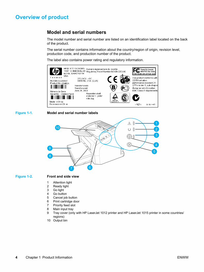
Model and serial numbersThe model number and serial number are listed on an identification label located on the backof the product.
The serial number contains information about the country/region of origin, revision level,production code, and production number of the product.
The label also contains power rating and regulatory information.
Figure 1-1. Model and serial number labels
110
9
8
7 6
2
3
5
4
Figure 1-2. Front and side view1 Attention light2 Ready light3 Go light4 Go button5 Cancel job button6 Print cartridge door7 Priority feed slot8 Main input tray9 Tray cover (only with HP LaserJet 1012 printer and HP LaserJet 1015 printer in some countries/
regions)10 Output bin
4 Chapter 1 Product Information ENWW

11
12
13
1415
Figure 1-3. Back and side view11 USB port12 Parallel port (HP LaserJet 1015 printer only)13 On/off switch14 Power receptacle15 Separation pad
Hardware descriptionThe HP LaserJet 1010 product provides 600 x 600 dpi printing. The HP LaserJet 1012, and1015 offer 600 x 600 x 2 dpi printing (effectively 1200 dot per inch (dpi) using HP REttechnology).
The product prints at 12 pages per minute (HP LaserJet 1010) or 15 ppm for letter-size paperand 14 ppm for A4-size paper (HP LaserJet 1012 and HP LaserJet 1015). With 600 dpiprinting for the HP LaserJet 1010 printer and an effective 1200 dpi printing resolution for theother models, the product has exceptional text and graphics print quality. The simple controlpanel and improved paper handling make this product very easy to use.
The main input tray has a 150-sheet (20 lb paper) capacity for continuous, multiple-pageprinting. The priority input tray is used for manual feeding single sheets of mostrecommended media and will hold up to ten sheets of 20 lb paper. Both trays are center-justified for all supported paper sizes. The output bin holds up to 125 sheets of 20 lb paper.
The product has a very fast first-page-out, at less than eight seconds. The base memorycontains 8 MB of RAM, and an embedded 133 MHz processor.
The print engine has an average duty cycle of 1,000 pages per month (7,000 peak). Thestandard toner life is 2,000 pages with 5 percent toner coverage.
ENWW Overview of product 5

Firmware description The firmware in the product includes:
● Host based printing
● PCL Level 5e (HP LaserJet 1015 printer)
● EconoMode functionality
The 1012 and 1015 firmware has Resolution Enhancement technology (REt).
6 Chapter 1 Product Information ENWW

Product Specifications
Table 1-1. Physical specifications
Product Height Depth Width Weight
physicaldimensions
208 mm(8.2 in)
230 mm(9.1 in)
370 mm(14.6 in)
5.9 kg(13 lbs)
Table 1-2. Environmental specifications
Category Specification
Operating environment (unit plugged into an ACoutlet)
● Temperature: 10° to 32.5° C (50° to 90.5° F)
● Humidity: 20 to 80 percent relative humidity(no condensation)
Storage environment (unit not plugged into an ACoutlet)
● Temperature: 0° to 40° C (32° to 104° F)
● Humidity: 10 to 80 percent relative humidity(no condensation)
Table 1-3. Performance of HP LaserJet 1010
Item Value
Print resolution
Normal black and white 600 by 600 dpi
Print speed
A4, black and white 12 ppm
Table 1-4. Performance of HP LaserJet 1012 and 1015
Item Value
Print resolution
Normal black and white 600 by 600 x 2 (effective 1200 dpi resolutionusing HP REt technology) dpi
Print speed
A4, black and white 14 ppm
Table 1-5. Electrical specifications
Item 110-volt models 220-volt models
Power supply 110 to 127 V (+/- 10 %) 220 to 240 V (+/- 10 %)
50 to 60 Hz (+/- 2 Hz) 50 to 60 Hz (+/- 2 Hz)
ENWW Product Specifications 7

Item 110-volt models 220-volt models
Power consumption (typical)
During printing 250 W (average) 250 W (average)
During standby 2 W (average) 2 W (average)
Power Save mode 2 W (average) 2 W (average)
Off mode 0 W (average) 0 W (average)
Heat output
During printing X BTU/hr X BTU/hr
Minimum recommended circuitcapacity
4.5 A 2.3 A
Note Values subject to change. See http://www.hp.com/support/lj1010 for current information.
WARNING! Power sources are not interchangeable.
Activity level Operator (<1m) Bystander (1m) Sound power
Active LpAm56 dB (A) LpAm48 dB (A) LWAd6.1 Bels (A)
Idle LpAmN/A dB (A)(inaudible)
LpAmN/A dB (A)(inaudible)
LWAdN/A Bels (A)(inaudible)
Note Values subject to change. See http://www.hp.com/support/lj1010 for current information.During other operations, acoustic emissions may vary.
8 Chapter 1 Product Information ENWW

HEWLETT-PACKARD LIMITED WARRANTY STATEMENT
HP PRODUCTHP LaserJet 1010 series (1010, 1012, 1015)
DURATION OF LIMITED WARRANTYOne year from date of purchase.
HP warrants to you, the end-user customer, that HP hardware and accessories will be free from defects inmaterials and workmanship after the date of purchase, for the period specified above. If HP receives notice ofsuch defects during the warranty period, HP will, at its option, either repair or replace products which prove to bedefective. Replacement products may be either new or equivalent in performance to new.
HP warrants to you that HP software will not fail to execute its programming instructions after the date ofpurchase, for the period specified above, due to defects in material and workmanship when properly installed andused. If HP receives notice of such defects during the warranty period, HP will replace software which does notexecute its programming instructions due to such defects.
HP does not warrant that the operation of HP products will be uninterrupted or error free. If HP is unable, within areasonable time, to repair or replace any product to a condition as warranted, you will be entitled to a refund of thepurchase price upon prompt return of the product.
HP products may contain remanufactured parts equivalent to new in performance or may have been subject toincidental use.
Warranty does not apply to defects resulting from (a) improper or inadequate maintenance or calibration, (b)software, interfacing, parts or supplies not supplied by HP, (c) unauthorized modification or misuse, (d) operationoutside of the published environmental specifications for the product, or (e) improper site preparation ormaintenance.
TO THE EXTENT ALLOWED BY LOCAL LAW, THE ABOVE WARRANTIES ARE EXCLUSIVE AND NO OTHERWARRANTY OR CONDITION, WHETHER WRITTEN OR ORAL, IS EXPRESSED OR IMPLIED AND HPSPECIFICALLY DISCLAIMS ANY IMPLIED WARRANTIES OR CONDITIONS OF MERCHANTABILITY,SATISFACTORY QUALITY, AND FITNESS FOR A PARTICULAR PURPOSE. Some countries/regions, states orprovinces do not allow limitations on the duration of an implied warranty, so the above limitation or exclusion mightnot apply to you. This warranty gives you specific legal rights and you might also have other rights that vary fromcountry/region to country/region, state to state, or province to province. HP's limited warranty is valid in anycountry/region or locality where HP has a support presence for this product and where HP has marketed thisproduct. The level of warranty service you receive may vary according to local standards. HP will not alter form, fit,or function of the product to make it operate in a country/region for which it was never intended to function forlegal or regulatory reasons.
TO THE EXTENT ALLOWED BY LOCAL LAW, THE REMEDIES IN THIS WARRANTY STATEMENT ARE YOURSOLE AND EXCLUSIVE REMEDIES. EXCEPT AS INDICATED ABOVE, IN NO EVENT WILL HP OR ITSSUPPLIERS BE LIABLE FOR LOSS OF DATA OR FOR DIRECT, SPECIAL, INCIDENTAL, CONSEQUENTIAL(INCLUDING LOST PROFIT OR DATA), OR OTHER DAMAGE, WHETHER BASED IN CONTRACT, TORT, OROTHERWISE. Some countries/regions, states or provinces do not allow the exclusion or limitation of incidental orconsequential damages, so the above limitation or exclusion may not apply to you.
THE WARRANTY TERMS CONTAINED IN THIS STATEMENT, EXCEPT TO THE EXTENT LAWFULLYPERMITTED, DO NOT EXCLUDE, RESTRICT OR MODIFY AND ARE IN ADDITION TO THE MANDATORYSTATUTORY RIGHTS APPLICABLE TO THE SALE OF THIS PRODUCT TO YOU.
ENWW HEWLETT-PACKARD LIMITED WARRANTY STATEMENT 9

Extended warranty
In most countries/regions, HP Care Pack provides additional coverage, beyond standardwarranty for the HP device and for all HP-supplied internal components. This hardwaremaintenance can uplift the standard warranty, for example, from next-day to same-dayservice, and/or extend it up to 5 years. The HP Care Pack can provide Express Exchange oronsite service. For more information, see the support flyer that came with your device for theappropriate phone numbers and information.
10 Chapter 1 Product Information ENWW
Print cartridge information
The print cartridge is designed to simplify replacement of the major consumable parts. Theprint cartridge contains the printing mechanism and a supply of toner.
At 5 percent page coverage, a standard print cartridge will print approximately 2,000 pages.However, a cartridge should print more pages if it regularly prints pages with less coverage,such as short memos. The cartridge might print fewer pages if heavy or bold print is used.
For best results, always use a print cartridge before the expiration date stamped on thecartridge box.
Refilled print cartridges While Hewlett-Packard does not prohibit the use of refilled print cartridges during thewarranty period or while the product is under a maintenance contract, it is not recommendedfor the following reasons:
● Repairs resulting from the use of refilled cartridges are not covered under Hewlett-Packard warranty or maintenance contracts.
● Hewlett-Packard has no control or process to ensure that a refilled cartridge functions atthe high level of reliability of a new HP LaserJet toner cartridge. Hewlett-Packard alsocannot predict the long-term reliability effect on the product from using different tonerformulations found in refilled cartridges.
● The print quality of HP LaserJet print cartridges influences the customer’s perception ofthe product. Hewlett-Packard has no control over the actual print quality of a refilledcartridge.
● Parts that are critical to print quality may not be replaced when the cartridge is refilledwith toner.
Recycling print cartridges In order to reduce waste, Hewlett-Packard offers a recycling program. Cartridge componentsthat do not wear out are recycled. Plastics and other materials are recycled. Hewlett-Packardpays the shipping costs from the user to the recycling plant (within the United States). To jointhis recycling effort, follow the instructions inside the print cartridge box. Refer tohttp://www.hp.com/recycle for more information.
ENWW Print cartridge information 11

Declaration of Conformity
Declaration of Conformityaccording to ISO/IEC Guide 22 and EN 45014
Manufacturer Name: Hewlett-Packard CompanyManufacturer Address: 11311 Chinden Boulevard
Boise, , Idaho 83714-1021, USA
declares that the product
Product Name: HP LaserJet 1010 Series PrinterProduct Number: Q2460A, Q2461A, Q2462A, (Regulatory Model Number: BOISB-0207-00)Product Options: ALL
conforms to the following Product Specifications:
Safety: IEC 60950:1999 / EN 60950:2000IEC 60825-1:1993 +A1/ EN 60825-1:1994+A11 (Class 1 Laser/LED Product)GB4943:1995
EMC: CISPR 22:1997/ EN 55022:1998 Class B1
EN 61000-3-2:1995/A14EN 61000-3-3:1995EN 55024:1998FCC Title 47 CFR, Part 15 Class B2) / ICES-003, Issue 3AS / NZS 3548:1995 +A1 +A2 / GB9254:1998
Supplementary Information
The product herewith complies with the requirements of the following EMC Directive 89/336/EEC and the Low Voltage Directive 73/23/EEC,and carries the CE-marking accordingly.
1) The product was tested in a typical configuration with Hewlett-Packard Personal Computer Systems.
2) This Device complies with Part 15 of the FCC Rules. Operation is subject to the following two conditions: (1) this device may not causeharmful interference, and (2) this device must accept any interference received, including interference that may cause undesired operation.
3) For regulatory purposes, this product is assigned a Regulatory model number. This number should not be confused with the marketingname (HP LaserJet 1010) or the product numbers (Q2460A, Q2461A, Q2462A).
Product Regulations ManagerPO Box 15 Mail Stop 160
Boise, Idaho 83707-0015, USA(208-396-6000)
April 1, 2003
For regulatory topics only, contact:
Australia Contact Product Regulations Manager, Hewlett-Packard Australia, Ltd. 31-41 Joseph Street, Blackburn, Victoria 3130,Australia.
European Contact Your Local Hewlett-Packard Sales and Service Office or Hewlett-Packard Gmbh, Department HQ-TRE / StandardsEurope, Herrenberger Strasse 140, Böblingen, D-71034, (+49-7031-14-3143)
U.S.A. Contact Product Relations Manager, Hewlett-Packard Company PO Box 15, Mail Stop 160 Boise, ID 83707-0015, U.S.A.(208-396-6000)
12 Chapter 1 Product Information ENWW

For Regulatory Topics ONLY, contact:
Laser safety statementThe Center for Devices and Radiological Health (CDRH) of the U.S. Food and DrugAdministration has implemented regulations for laser products manufactured since August 1,1976. Compliance is mandatory for products marketed in the United States. The printer iscertified as a “Class 1” laser product under the U.S. Department of Health and HumanServices (DHHS) Radiation Performance Standard according to the Radiation Control forHealth and Safety Act of 1968.
Since radiation emitted inside the printer is completely confined within protective housingsand external covers, the laser beam cannot escape during any phase of normal useroperation.
WARNING! Using controls, making adjustments, or performing procedures other than those specified inthis user guide could result in exposure to hazardous radiation.
Canadian DOC regulationsComplies with Canadian EMC Class B requirements.
«Conforme á la classe B des normes canadiennes de compatibilité électromagnétiques.«CEM».»
Korean EMI statement
ENWW For Regulatory Topics ONLY, contact: 13

Laser statement for FinlandLASERTURVALLISUUS
LUOKAN 1 LASERLAITE
LASERLAITE KLASS 1 LASER APPARAT
HP LaserJet 1010 -laserkirjoitin on käyttäjän kannalta turvallinen luokan 1 laserlaite.Normaalissa käytössä kirjoittimen suojakotelointi estää lasersäteen pääsyn laitteenulkopuolelle. Laitteen turvallisuusluokka on määritetty standardin EN 60825-1 (1993)mukaisesti.
VAROITUS!
Laitteen käyttäminen muulla kuin käyttöohjeessa mainitulla tavalla saattaa altistaa käyttäjänturvallisuusluokan 1 ylittävälle näkymättömälle lasersäteilylle.
VARNING!
Om apparaten används på annat sätt än i bruksanvisning specificerats, kan användarenutsättas för osynlig laserstrålning, som överskrider gränsen för laserklass 1.
HUOLTO
HP LaserJet 1010 -kirjoittimen sisällä ei ole käyttäjän huollettavissa olevia kohteita. Laitteensaa avata ja huoltaa ainoastaan sen huoltamiseen koulutettu henkilö. Tällaiseksihuoltotoimenpiteeksi ei katsota väriainekasetin vaihtamista, paperiradan puhdistusta taimuita käyttäjän käsikirjassa lueteltuja, käyttäjän tehtäväksi tarkoitettuja ylläpitotoimia, jotkavoidaan suorittaa ilman erikoistyökaluja.
VARO!
Mikäli kirjoittimen suojakotelo avataan, olet alttiina näkymättömälle lasersäteilylle laitteenollessa toiminnassa. Älä katso säteeseen.
VARNING!
Om laserprinterns skyddshölje öppnas då apparaten är i funktion, utsättas användaren förosynlig laserstrålning. Betrakta ej strålen.
Tiedot laitteessa käytettävän laserdiodin säteilyominaisuuksista:
1) Aallonpituus 770-795 nm
2) Teho 5 mW
3) Luokan 3B laser
14 Chapter 1 Product Information ENWW

Installation and Operation
This chapter provides an overview of the appropriate operating environment, describes thecontrol panel, and describes media requirements and loading media to print.
Operating environment .......................................................................................................... 16Identifying the control panel components...............................................................................17Product media specifications..................................................................................................18
Supported media sizes (printer).......................................................................................18Guidelines for using media.....................................................................................................19
Paper and Transparencies ..............................................................................................19Common media problems table .......................................................................................19Labels ..............................................................................................................................19Envelopes ........................................................................................................................ 20Card stock and heavy media ...........................................................................................20
Loading media ....................................................................................................................... 22Loading media to print......................................................................................................22
ENWW 15
Operating environment
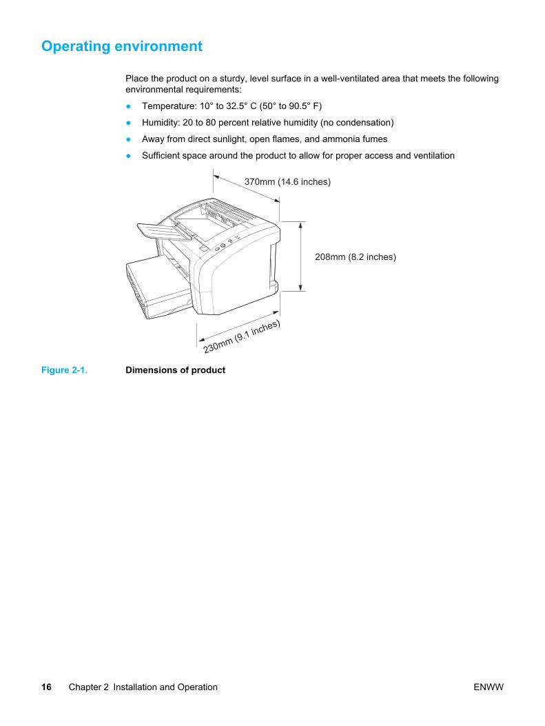
Place the product on a sturdy, level surface in a well-ventilated area that meets the followingenvironmental requirements:
● Temperature: 10° to 32.5° C (50° to 90.5° F)
● Humidity: 20 to 80 percent relative humidity (no condensation)
● Away from direct sunlight, open flames, and ammonia fumes
● Sufficient space around the product to allow for proper access and ventilation
208mm (8.2 inches)
370mm (14.6 inches)
230mm (9.1 inches)
Figure 2-1. Dimensions of product
16 Chapter 2 Installation and Operation ENWW
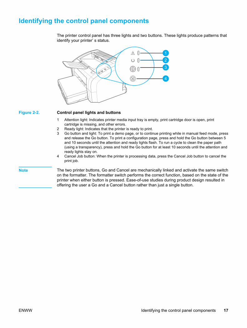
Identifying the control panel components
The printer control panel has three lights and two buttons. These lights produce patterns thatidentify your printer’ s status.
1
2
3
4
Figure 2-2. Control panel lights and buttons1 Attention light: Indicates printer media input tray is empty, print cartridge door is open, print
cartridge is missing, and other errors.2 Ready light: Indicates that the printer is ready to print.3 Go button and light: To print a demo page, or to continue printing while in manual feed mode, press
and release the Go button. To print a configuration page, press and hold the Go button between 5and 10 seconds until the attention and ready lights flash. To run a cycle to clean the paper path(using a transparency), press and hold the Go button for at least 10 seconds until the attention andready lights stay on.
4 Cancel Job button: When the printer is processing data, press the Cancel Job button to cancel theprint job.
Note The two printer buttons, Go and Cancel are mechanically linked and activate the same switchon the formatter. The formatter switch performs the correct function, based on the state of theprinter when either button is pressed. Ease-of-use studies during product design resulted inoffering the user a Go and a Cancel button rather than just a single button.
ENWW Identifying the control panel components 17

Product media specifications
The product accepts a variety of media. Properties such as weight, grain, and moisturecontent are important factors affecting printer performance and output quality. Media shouldconform to the guidelines in the User Guide located on the product CD. Media that does notmeet HP guidelines might cause poor print quality, increased media jams, or premature wearon the product. This may require repair.
CAUTION Damage caused by media that does not meet HP’s specifications is not covered by the HPwarranty or service agreements.
Supported media sizes (printer)The printer supports media within these sizes:
● Minimum: 76 x 127 mm (3 x 5 in)
● Maximum: 216 x 356 mm (8.5 x 14 in)
Table 2-1. Media types
Paper type Metric English
Letter 216 x 279 mm 8.5 x 11 in
Legal 216 x 356 mm 8.5 x 14 in
Executive 184 x 267 mm 7.25 x 10.5 in
A4 210 x 297 mm 8.25 x 11.75 in
COM10 Envelopes 105 x 241 mm 4.13 x 9.5 in
DL Envelopes 110 x 220 mm 4.33 x 8.67 in
C5 Envelopes 162 x 229 mm (6.4 x 9 in)
B5 Envelopes 176 x 250 mm (6.9 x 9.85 in)
Monarch Envelopes 98.5 x 191 mm (3.88 x 7.5 in)
Custom size media custom custom
Note Narrow and heavy media can cause the printer to print slower.
18 Chapter 2 Installation and Operation ENWW
Guidelines for using media
HP LaserJet printers produce excellent print quality documents. You can print on a variety ofmedia, such as paper (including up to 100 percent recycled fiber content paper), envelopes,labels, transparencies, and custom-sized media.
Paper and Transparencies Paper must be of good quality and free of cuts, nicks, tears, spots, loose particles, dust,wrinkles, holes, and curled or bent edges. Check the label on the paper package for detailsabout the type of paper (such as bond or recycled).
Some paper causes print quality problems, jamming, or damage to the printer.
Note Do not use letterhead that is printed with low-temperature inks, such as those used in sometypes of thermography, raised letterhead, or colored paper or preprinted forms that use inksincompatible with the printer temperature [200° C (392° F) for 0.1 second].
Transparencies must be able to withstand 200° C (392° F), the printer’s maximumtemperature.
Common media problems table
Symptom Problem with paper Solution
Poor print quality or toneradhesion, or problems withfeeding.
Too moist, too rough, toosmooth, or embossed. Faultypaper lot.
Try another kind of paperbetween 100 and 250 Sheffieldand 4 to 6 percent moisturecontent.
Dropouts, jamming, or curl. Stored improperly. Store paper flat in its moisture-proof wrapping.
Increased gray backgroundshading.
Might be too heavy. Use lighter paper.
Excessive curl, or problems withfeeding.
Too moist, wrong graindirection, or short-grainconstruction.
Use long-grain paper. Printusing the straight-throughoutput path.
Jamming, or damage to printer. Cutouts or perforations. Do not use paper with cutoutsor perforations.
Problems with feeding. Ragged edges. Use good quality paper.
LabelsWhen selecting labels, consider the following factors:
● Adhesives: The adhesive material should be stable at 200° C (392° F), the printer’smaximum temperature.
● Arrangement: Only use labels with no exposed backing between them. Labels can peeloff sheets that have spaces between the labels, causing serious jams.
ENWW Guidelines for using media 19

● Curl: Prior to printing, labels must lie flat with no more than 13 mm (0.5 in) of curl in anydirection.
● Condition: Do not use labels with wrinkles, bubbles, or other indications of separation.Never use a sheet of labels that has already been run through the printer.
Envelopes Envelope construction is critical. Envelope fold lines can vary considerably, not only betweenmanufacturers, but also within a box from the same manufacturer. Successful printing onenvelopes depends on the quality of the envelopes. When selecting envelopes, consider thefollowing factors:
● Weight: The weight of the envelope paper should not exceed 105 g/m2 (28 lb), orjamming might result.
● Construction: Prior to printing, envelopes should lie flat with less than 6 mm (0.25 in)curl and should not contain air. Envelopes that trap air may cause problems.
● Condition: Make sure that the envelopes are not wrinkled, nicked, or otherwisedamaged.
● Sizes: From 90 x 160 mm (3.5 x 6.3 in) to 178 x 254 mm (7 x 10 in).
Store envelopes flat. If air is trapped in an envelope, creating an air bubble, the envelopemight wrinkle during printing.
Envelopes with double-side seamsAn envelope with double-side-seam construction (vertical seams at both ends of theenvelope rather than diagonal seams) is more likely to wrinkle. Make sure the seam extendsall the way to the corner of the envelope as shown in top figure of the following illustration:
Should print well.
May jam or wrinkle.
Envelopes with adhesive strips or flapsEnvelopes with a peel-off adhesive strip or with more than one flap that folds over to sealmust use adhesives compatible with the heat and pressure in the printer: 200°C (392° F).The extra flaps and strips might cause wrinkling, creasing, or jams.
Card stock and heavy media For optimum performance, do not use paper heavier than 157 g/m 2 (42-lb). Paper that is tooheavy might cause misfeeds, stacking problems, paper jams, poor toner fusing, poor printquality, or excessive mechanical wear.
20 Chapter 2 Installation and Operation ENWW

Note You might be able to print on heavier paper if you do not fill the input tray to capacity and ifyou use paper with a smoothness rating of 100 to 180 Sheffield.
Card stock construction● Smoothness: 135-157 g/m 2 (36-to 42-lb) card stock should have a smoothness rating of
100 to 180 Sheffield. 60-135 g/m 2 (16- to 36-lb) card stock should have a smoothnessrating of 100 to 250 Sheffield.
● Construction : Card stock should lie flat with less than 5 mm (0.2 in) of curl.
● Condition: Make sure that the card stock is not wrinkled, nicked, or otherwise damaged.
● Sizes: Only use card stock within the following size ranges:
● Minimum: 76 x 127 mm (3 x 5 in)
● Maximum: 216 x 356 mm (8.5 x 14 in)
Card stock guidelines● Set margins at least 2 mm (0.08 in) away from the edges.
ENWW Guidelines for using media 21
Loading media
Loading media in the HP LaserJet 1010 series printers is simple and straightforward.
Loading media to printThis section describes loading bulk media to print.
Main input trayThe main input tray holds up to 150 sheets of 75 g/m2 (20 lb) paper or a 25 mm (0.98 in)stack of heavier media. Load media with the top forward and the side to be printed facing up.To prevent jams and skew, always adjust the side media guides.
Priority input trayThe priority input tray can be used to feed one page at a time of a recommended media formanual feeding and special operations. It can hold up to ten pages of 75 g/m2 (20 lb) paper,but is best used for feeding one page at a time of paper, heavier paper, envelope,transparency, or card stock. Load media with the top forward and the side to be printedfacing up. To prevent jams and skew, always adjust the side media guides.
If you try to print on media that is wrinkled, folded, or damaged in any way, a jam mightoccur. See the User Guide located on the product CD for more information.
Note When you add new media, make sure that you remove all of the media from the input trayand straighten the stack of new media. This helps prevent multiple sheets of media fromfeeding through the printer at one time, reducing paper jams.
Specific types of media ● Transparencies and labels: Load transparencies and labels with the top forward and
the side to be printed facing up. See the User Guide located on the product CD for moreinformation.
● Envelopes: Load envelopes with the narrow, stamp side forward and the side to beprinted facing up. See the User Guide located on the product CD for more information.
● Letterhead or preprinted forms: Load with the top forward and the side to be printedfacing up. See the User Guide for more information.
● Cards and custom-sized media: Load with the narrow side forward and the side to beprinted facing up. See the User Guide located on the product CD for more information.
22 Chapter 2 Installation and Operation ENWW

Maintenance
This chapter describes the life expectancy of parts that wear, printer cleaning, printermaintenance, and the replacement of user-replaceable parts.
Life expectancies of parts that wear ......................................................................................24Cleaning the product............................................................................................................... 25
Cleaning the print path.....................................................................................................25Cleaning the print cartridge area......................................................................................26Cleaning the printer pickup roller .....................................................................................27
User-replaceable parts ........................................................................................................... 29Replacing the printer pickup roller ...................................................................................29Replacing the printer separation pad................................................................................31Replacing the main input tray (paper pickup tray assembly)............................................33Replacing the output tray extension (delivery tray assembly)..........................................34
ENWW 23

Life expectancies of parts that wear
Inspect any parts that wear when servicing the product. Replace them as needed, based onfailure or wear, rather than on usage.
The following table lists approximate schedules for replacing consumables.
Table 3-1. Life expectancies of parts that wear
Description Part number Life (estimated) Remarks
Print cartridge (user-replaceable)
Q2612A 2,000 pages
Note
The estimated printcartridge life is basedon letter- or A4-sizedpaper with an averageof 5 percent tonercoverage and amedium densitysetting. Print cartridgelife can be extendedfurther by conservingtoner using draft modesettings.
When print becomesfaint, redistribute thetoner in the cartridgeby gently rotating thecartridge from side toside or replace thecartridge.
Pickup roller RL1-0266-000CN 50,000 pages Affects paper pickup.
Printer separation pad RC1-2095-000CN 50,000 pages Affects paperseparation (feedingone page at a time).
Fuser assembly RM1-0650-000CN 50,000 pages Can affect print qualityand/or papermovement.
Fuser assembly (220-240 V)
RG9-1494-030CN 50,000 pages Can affect print qualityand/or papermovement.
24 Chapter 3 Maintenance ENWW

Cleaning the product
WARNING! Before you perform these steps, unplug the product to avoid shock hazard.
To maintain quality, thoroughly clean the product:
● Any time a new print cartridge is installed.
● After printing approximately 2,000 pages.
● Whenever print quality problems appear.
Clean the outside of the product with a water-dampened cloth. Clean the inside with only adry, lint-free cloth (such as a lens tissue).
CAUTION To avoid permanent damage to the product, do not use ammonia-based or ethyl alcohol-based cleaners on or around the product.
WARNING! Avoid touching the heating element in the fuser. It might be very hot and can cause burns.
CAUTION Do not touch the surface of the black sponge transfer roller. Contaminants on the roller cancause print quality problems.
Cleaning the print pathThe HP LaserJet 1010 series printer features a special cleaning mode to clean the paperpath.
Note This process requires a transparency to remove dust and toner from the print paper path. Donot use bond or rough paper.
Make sure the transparency used in this cleaning process meets the media requirements forthe printer.
If transparency film is unavailable, you can use copier grade paper (18 to 24 lb. or 70 to90 g/m2) with a smooth surface. If you must use paper, perform the procedure two or threetimes to ensure proper cleaning.
1. Load a transparency in the priority input tray.
2. Make sure that the printer is idle and the Ready light is on.
3. Load the media in the input tray.
4. Access the HP toolbox. Click the Troubleshooting tab, and click Print Quality Tools.Select the cleaning page.
Note The cleaning process can also be initiated by holding down the Go button for approximately12.5 seconds.
Note The cleaning process takes approximately 2 minutes. The cleaning page will stop periodicallyduring the cleaning process. Do not turn the printer off until the cleaning process hasfinished. You might need to repeat the cleaning process several times to thoroughly clean theprinter.
ENWW Cleaning the product 25

Cleaning the print cartridge areaYou do not need to clean the print cartridge area often. However, cleaning this area canimprove the quality of your printed sheets.
1. Turn off the printer, unplug the power cord, and wait for the printer to cool.
2. Open the print cartridge door, and remove the print cartridge.
CAUTION To prevent damage, do not expose the print cartridge to light. Cover the print cartridge ifnecessary. Also, do not touch the black sponge transfer roller inside the printer. By doing so,you can damage the printer.
3. With a dry, lint-free cloth, wipe any residue from the media path area and the printcartridge cavity.
26 Chapter 3 Maintenance ENWW

4. Replace the print cartridge, and close the print cartridge door.
5. Plug in the printer, and turn it on.
Cleaning the printer pickup roller If you want to clean the pickup roller rather than replace it, follow the instructions below:
ENWW Cleaning the product 27
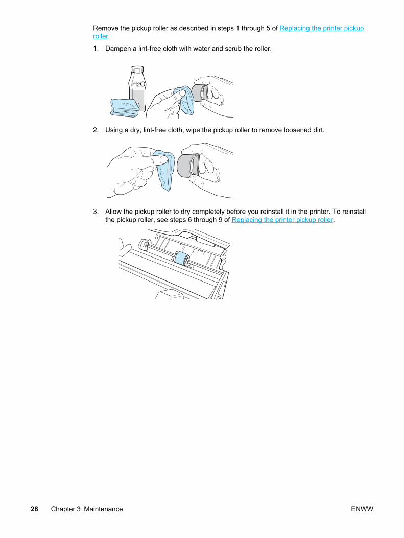
Remove the pickup roller as described in steps 1 through 5 of Replacing the printer pickuproller.
1. Dampen a lint-free cloth with water and scrub the roller.
H2O
2. Using a dry, lint-free cloth, wipe the pickup roller to remove loosened dirt.
3. Allow the pickup roller to dry completely before you reinstall it in the printer. To reinstallthe pickup roller, see steps 6 through 9 of Replacing the printer pickup roller.
28 Chapter 3 Maintenance ENWW

User-replaceable parts
To order a new pickup roller or separation pad, go to http://partsdirect.hp.com.
Replacing the printer pickup rollerIf the printer regularly misfeeds (no media feeds through) and cleaning the pickup roller doesnot fix it, replace the pickup roller.
CAUTION Failure to complete all the steps in this procedure might damage the product.
1. Turn off the printer, unplug the power cord, and wait for the printer to cool.
2. Open the print cartridge door, and remove the print cartridge.
3. Locate the pickup roller.
ENWW User-replaceable parts 29

4. Gently release the small, white tabs on each side of the pickup roller by pushing themaway from the roller, and then rotate the pickup roller toward the front.
CAUTION Use gentle pressure to release the small white tabs to avoid breaking them.
5. Gently pull the pickup roller up and out.
6. Position the new pickup roller in the slot of the previous pickup roller.
Note Circular and rectangular pegs on each side prevent you from incorrectly positioning thepickup roller.
7. Rotate the top of the new pickup roller into position until the white tabs on each side ofthe roller snap the roller into place.
30 Chapter 3 Maintenance ENWW

8. Reinstall the print cartridge and close the print cartridge door.
9. Plug in the printer, and turn it on.
Replacing the printer separation padIf the printer grabs more than one page at a time, you might have to replace the printerseparation pad. Recurring feed problems indicate that the printer separation pad is worn.
Note Before you change the separation pad, clean the pickup roller. See Cleaning the printerpickup roller for instructions. To order parts, go to http://partsdirect.hp.com.
ENWW User-replaceable parts 31

Note The following procedure requires a #2 Phillips-head screwdriver.
1. Turn off the printer, unplug the power cord, and wait for the printer to cool.
2. At the back of the printer, unscrew the two screws holding the separation pad in place.
3. Remove the separation pad.
32 Chapter 3 Maintenance ENWW

4. Insert the new separation pad, and screw it in place.
5. Plug the printer in, and turn it on.
Replacing the main input tray (paper pickup tray assembly)If you break or damage the main input tray (also called the paper pickup tray assembly), youcan replace it. To order parts, go to http://partsdirect.hp.com.
1. Carefully flex the main input tray just enough to release one side.
Note Take care not to break the hinge points.
2. Remove the main input tray.
ENWW User-replaceable parts 33

Replacing the output tray extension (delivery tray assembly)If you break or damage the output tray extension (also called the delivery tray assembly), youcan replace it. To order parts, go to http://partsdirect.hp.com.
1. Carefully flex the output tray extension just enough to release one side.
Note Take care not to break the hinge points.
2. Remove the output tray extension.
34 Chapter 3 Maintenance ENWW

Operational overview
This chapter describes the general components of the HP LaserJet 1010 series and theirtheory of operation.
Basic functions........................................................................................................................ 36Formatter system.................................................................................................................... 37
Central processing unit ....................................................................................................37RAM.................................................................................................................................. 37Universal Serial Bus interface..........................................................................................37Parallel interface (HP LaserJet 1015 only).......................................................................37Control panel.................................................................................................................... 37Draft mode ....................................................................................................................... 38MEt................................................................................................................................... 38Enhanced I/O ................................................................................................................... 38PJL overview ................................................................................................................... 38
Printer functions...................................................................................................................... 39Engine control system (engine control unit and power assembly)...................................39Image formation system...................................................................................................43Printer paper feed system................................................................................................44Jam detection .................................................................................................................. 46Solenoid, sensors, and switches......................................................................................46Basic sequence of operation (formatter-to-printer)...........................................................47
ENWW 35
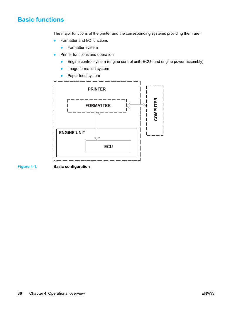
Basic functions
The major functions of the printer and the corresponding systems providing them are:
● Formatter and I/O functions
● Formatter system
● Printer functions and operation
● Engine control system (engine control unit--ECU--and engine power assembly)
● Image formation system
● Paper feed system
PRINTER
FORMATTER
ENGINE UNIT
ECU
COM
PUTE
R
Figure 4-1. Basic configuration
36 Chapter 4 Operational overview ENWW

Formatter system
The formatter coordinates the major systems. It is responsible for the following:
● Receiving and processing print data from the printer interface (from the computer)
● Monitoring the control panel and relaying printer status information
● Developing and coordinating data placement and timing with the print engine
● Communicating with the host computer through the bidirectional interface
The formatter receives print data from the parallel interface or the Universal Serial Bus (USB)interface and converts it into a dot image. The ECU synchronizes the image formationsystem with the paper feed system and signals the formatter to send the print image data tothe laser system. The formatter sends the print image data (dots) in the form of a videosignal, and the printing process begins.
Central processing unit The formatter uses an embedded Coldfire V4 microprocessor operating at 133 MHz.
RAM● One bank of nonvolatile RAM (NVRAM) stores parameters.
● Dynamic random access memory (DRAM) provides temporary storage of the productprogram code and print data.
● The HP LaserJet 1010 and 1012 have 8 MB of RAM.
● The HP LaserJet 1015 has 16 MB of RAM.
Universal Serial Bus interfaceThe formatter receives incoming data through the USB interface. This interface provideshigh-speed, two-way communication between the product and the host, allowing applicationson the host computer to change product settings and monitor product status. The USBinterface is compatible with the USB 2.0 specification.
Parallel interface (HP LaserJet 1015 only)If the parallel interface on the HP LaserJet 1015 is used, the formatter receives incomingdata through bidirectional ECP. Like the USB interface, the parallel interface supports high-speed, two-way communication between the product and the host, so applications on thehost computer can change product settings and monitor product status. Use an IEEE 1284-compliant parallel cable.
Control panelThe control panel consists of:
● Three status lights.
● Go and Cancel Job buttons
ENWW Formatter system 37

Draft mode Depending on which driver is used, selecting draft or EconoMode from the driver allows theproduct to use approximately 50 percent less toner, extending the life of the print cartridge.
MEtHP MEt effectively doubles the standard memory through a variety of font and data-compression methods.
Enhanced I/O The Enhanced I/O feature allows product memory to be used for storing data received fromthe host computer. When Enhanced I/O is enabled, you can send more data to the product inshorter amounts of time, which allows you to return to your application sooner. Enhanced I/Ohas the following options:
● Auto —allows the product to use Enhanced I/O memory allocation to increase the speedof data transfer from the host computer to the product, if necessary. The default setting isAuto.
● Off —uses the minimum amount of product memory for storing data sent from the hostcomputer.
● Page protect—allows the formatter to create the entire page image in page buffermemory before physically moving the media through the printer. This process ensuresthat the entire page will be printed.
Page complexity (ruling lines, complex graphics, or dense text) can exceed the printer’sability to create the page image fast enough to keep pace with the image formation process.If Page Protect is disabled and a page is too complex, the page might print in parts (forexample, the top half on one page and the bottom half on the next page). Some print-dataloss is likely in these instances, and the product will display an error message.
PJL overview When using the parallel port on the HP LaserJet 1015, Printer Job Language (PJL) is anintegral part of configuration (in addition to the standard Printer Command Language--PCL).With IEEE 1284-compliant parallel cable (standard ECP cabling), PJL allows the product toperform functions such as:
● Two-way communication with the host computer through a bidirectional parallelconnection. The product can communicate information to the host (such as the controlpanel status).
● Isolation of print environment settings from one print job to the next. For example, if aprint job is sent to the printer in landscape mode, the subsequent print jobs print inlandscape only if they are formatted for landscape printing.
Note PJL commands can be sent to the printer only from a DOS command prompt and through aparallel cable, and thus apply only to the HP LaserJet 1015. DOS applications are notsupported over a USB interface.
38 Chapter 4 Operational overview ENWW
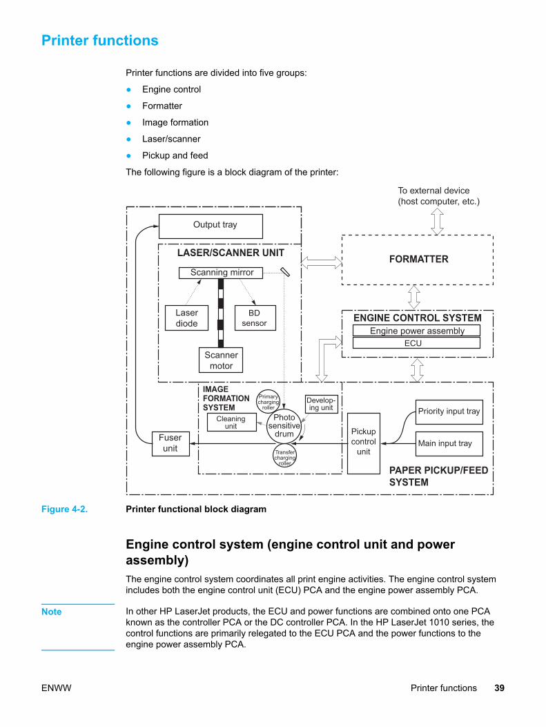
Printer functions
Printer functions are divided into five groups:
● Engine control
● Formatter
● Image formation
● Laser/scanner
● Pickup and feed
The following figure is a block diagram of the printer:
Output tray
Priority input tray
Main input tray
To external device�(host computer, etc.)
Scanning mirror
Laser�diode
Cleaning�unit
Fuser�unit
Primary�charging�
roller
Photo�sensitive�
drum
Engine power assembly
FORMATTER
ENGINE CONTROL SYSTEM
PAPER PICKUP/FEED�SYSTEM
IMAGE�FORMATION�SYSTEM
LASER/SCANNER UNIT
BD�sensor
Scanner�motor
ECU
Pickup�control�
unit
Develop-�ing unit
Transfer�charging�
roller
Figure 4-2. Printer functional block diagram
Engine control system (engine control unit and powerassembly)The engine control system coordinates all print engine activities. The engine control systemincludes both the engine control unit (ECU) PCA and the engine power assembly PCA.
Note In other HP LaserJet products, the ECU and power functions are combined onto one PCAknown as the controller PCA or the DC controller PCA. In the HP LaserJet 1010 series, thecontrol functions are primarily relegated to the ECU PCA and the power functions to theengine power assembly PCA.
ENWW Printer functions 39

The ECU controls the following systems and functions:
● Printer engine control
● Paper motion monitoring and control (printing)
● Motor
● Printer laser/scanner unit
The engine power assembly provides the power system:
● AC power distribution
● DC power distribution
● Overcurrent/overvoltage protection
● High-voltage power distribution
Printer engine control systemPaper motion monitoring and control
The ECU controls paper motion in the printer by continuously monitoring the two papersensors and coordinating the timing with the other print processes.
For a detailed explanation of paper movement and the interaction of the sensors and pickupsolenoid with the paper movement process, see Printer paper feed system.
Motor
The ECU controls the motor. The motor drives all of the printer paper movement.
Printer laser/scanner unit The ECU sends signals to the laser/scanner assembly to modulate the laser diode's on andoff modes and to drive the laser/scanner motor.
40 Chapter 4 Operational overview ENWW

VDO
/VDO
CNT0
CNT1
/BDI
/BD
/ACC/DEC
Formatter
Laser driver PCB
Focusing lensScanner motorFour-sidedmirror
Cylindrical lens
BDsensor
Enginecontroller
PCB
Photosensitivedrum
Figure 4-3. Laser/scanner operation
Power system on the engine power assemblyThe AC, DC, and high-voltage power supply circuits are all provided by the engine powerassembly.
AC power distribution
The AC power circuitry supplies AC voltage whenever the power cord is connected to the ACpower source and the power switch is on. AC voltage is distributed to the DC power supplycircuitry and to the AC driver circuitry, which controls AC voltage to the fuser assemblyheating element.
DC power distribution
The DC power distribution circuitry, located on the engine power assembly, distributes +3.3Vdc, +5 Vdc, and +24 Vdc as follows:
● +3.3 Vdc: ECU, sensors, formatter
● +5 Vdc: Parallel interface on the 1015 formatter
● +24 Vdc: Main motor, laser/scanner motor, solenoid, high-voltage power supply, fuser, safety circuit, doorswitch
Overcurrent/overvoltage
ENWW Printer functions 41

There are two overvoltage devices in this product:
● Fuse F101 provides overcurrent protection for the fusing system circuitry.
● Fuse F102 (110V products only) provides overcurrent protection to the printer DC powersupply circuitry.
You can check or replace the fuses by removing the left cover. If either of these fuses fail,replace the engine power assembly.
High-voltage power distribution
The high-voltage power supply applies an overlap of DC and AC voltage to the primarycharging roller and to the developing roller. This circuit also applies a positive or negative DCvoltage to the transfer roller according to the instructions from the engine control unit.
This circuit also controls the image density by changing the primary AC voltage and thedeveloping AC bias according to the print density setting (which is set using HP Toolbox).
High voltage is disabled when the print cartridge door is open.
PR1
TRS
DEV
IC902
CPU
DVAC
TRNDC
TRCRNT
TRPDC
PRAC
PRPWM IC301
IC301IC301
IC301
IC501
Positive voltagegeneration circuit
J303
J304
J301
J302
DC voltagegeneration
circuit
AC voltagegeneration
circuit
DC voltagegeneration
circuit
AC voltagegeneration
circuit
Combined
Combined
Primarycharging roller
Developingcylinder
Transfercharging
roller
Engine controller PCB
High-voltage power supply circuit
Developing bias circuit
Transfer charging bias circuit
Negative voltagegeneration circuit
Photosensitivedrum
Primary charging bias circuit
J201-14J902-10
J201-15J902-9
J201-16J902-8
J201-18J902-6
J201-17J902-7
J201-22J902-2
Power supply PCB
Figure 4-4. High-voltage power supply circuit
42 Chapter 4 Operational overview ENWW
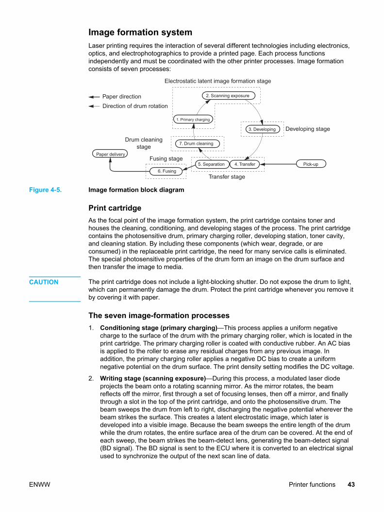
Image formation systemLaser printing requires the interaction of several different technologies including electronics,optics, and electrophotographics to provide a printed page. Each process functionsindependently and must be coordinated with the other printer processes. Image formationconsists of seven processes:
Electrostatic latent image formation stage
Paper directionDirection of drum rotation
2. Scanning exposure
3. Developing
4. Transfer5. Separation6. Fusing
7. Drum cleaning
Paper delivery
Pick-up
1. Primary charging
Fusing stage
Transfer stage
Developing stage
Drum cleaning�stage
Figure 4-5. Image formation block diagram
Print cartridgeAs the focal point of the image formation system, the print cartridge contains toner andhouses the cleaning, conditioning, and developing stages of the process. The print cartridgecontains the photosensitive drum, primary charging roller, developing station, toner cavity,and cleaning station. By including these components (which wear, degrade, or areconsumed) in the replaceable print cartridge, the need for many service calls is eliminated.The special photosensitive properties of the drum form an image on the drum surface andthen transfer the image to media.
CAUTION The print cartridge does not include a light-blocking shutter. Do not expose the drum to light,which can permanently damage the drum. Protect the print cartridge whenever you remove itby covering it with paper.
The seven image-formation processes 1. Conditioning stage (primary charging)—This process applies a uniform negative
charge to the surface of the drum with the primary charging roller, which is located in theprint cartridge. The primary charging roller is coated with conductive rubber. An AC biasis applied to the roller to erase any residual charges from any previous image. Inaddition, the primary charging roller applies a negative DC bias to create a uniformnegative potential on the drum surface. The print density setting modifies the DC voltage.
2. Writing stage (scanning exposure)—During this process, a modulated laser diodeprojects the beam onto a rotating scanning mirror. As the mirror rotates, the beamreflects off the mirror, first through a set of focusing lenses, then off a mirror, and finallythrough a slot in the top of the print cartridge, and onto the photosensitive drum. Thebeam sweeps the drum from left to right, discharging the negative potential wherever thebeam strikes the surface. This creates a latent electrostatic image, which later isdeveloped into a visible image. Because the beam sweeps the entire length of the drumwhile the drum rotates, the entire surface area of the drum can be covered. At the end ofeach sweep, the beam strikes the beam-detect lens, generating the beam-detect signal(BD signal). The BD signal is sent to the ECU where it is converted to an electrical signalused to synchronize the output of the next scan line of data.
ENWW Printer functions 43

3. Developing stage—During this process, the latent electrostatic image is present on thedrum. The toner particles obtain a negative surface charge by rubbing against thedeveloping cylinder, which is connected to a negative DC supply. The negatively chargedtoner is attracted to the discharged (exposed, grounded) areas of the drum, and it isrepelled from the negatively charged (unexposed) areas.
4. Transfer stage—During this process, the toner image on the drum surface is transferredto the media. The transfer roller applies a positive charge to the back of the media, whichattracts the negatively charged toner on the drum surface to the media. After separation,the drum is cleaned and conditioned for the next image.
5. Separation stage—During this process, the media separates from the drum. To stabilizethe feed system and prevent toner dropouts on the printed image at low temperature andhumidity, the static eliminator reduces the charge on the back of the media.
6. Fusing stage—During this process, the heat and pressure fuse the toner into the mediato produce a permanent image. The media passes between a heated fusing element anda soft pressure roller, which melt the toner and press it into the media.
7. Drum-cleaning stage—During this process, the cleaning blade is in contact with thesurface of the drum at all times. As the drum rotates during printing, the cleaning bladewipes excess toner off the drum and stores it in the waste toner receptacle.
Printer paper feed systemThe main input tray and the priority input tray merge into one main input area. The printersenses the paper as it enters the paper feed path via the top of page sensor (PS801). It doesnot sense the presence of media prior to beginning the print cycle. The following steps occurwhen the product receives a print job:
Step 1 The ECU activates the motor (M1). Paper motionbegins when the ECU energizes the pick-upsolenoid (SL1).
Step 2 The paper pickup roller rotates once. The paperlift plate pushes the media against the pickuproller.
Step 3 The friction of the pickup roller grabs the topsheet and advances it to the feed assembly driverollers. To ensure that only one sheet is fed, amain separation pad holds the remainder of thestack in place.
Step 4 The feed assembly drive rollers advance themedia to the top-of-page sensor (PS801). Thissensor informs the ECU of the exact location ofthe leading edge of media, so that the imagebeing written on the photosensitive drum can beprecisely positioned on the page.
Step 5 The feed assembly drive rollers then advance themedia to the transfer area where the toner imageon the photosensitive drum is transferred to themedia.
44 Chapter 4 Operational overview ENWW

Step 6 After the image is transferred, the media entersthe fuser assembly where heat from the fuserand pressure from the pressure rollerpermanently bond the toner image to media. Thepaper delivery sensor (PS803) determines thatthe media has successfully moved out of thefusing area.
Step 7 The fuser assembly exit rollers deliver media tothe paper output bin face down.
Pick-up roller
Transferroller
Delivery roller
Priority input tray
Main input tray
Pressure roller
Fuser
SL1
Engine controller PCB
Formatter
M1
PS801PS802
PS803
Separationpad
PA
PE
R D
ELI
VE
RY
DE
TE
CT
ION
sig
unal
(/P
OS
NS
)
TO
P O
F P
AG
E D
ET
EC
TIO
N s
igna
l (/P
ISN
S)
PIC
K-U
P S
OLE
NO
ID D
RIV
E s
igna
l (C
PU
D)
MA
IN M
OT
OR
DR
IVE
sig
nals
Photo-sensitivedrum
PS801: Top of page sensorPS802: Paper width sensorPS803: Paper delivery sensorM1: Main motorSL1: Pick-up solenoid
PA
PE
R W
IDT
H D
ET
EC
TIO
N s
igna
l (/P
WS
NS
)
Figure 4-6. Printer paper path
ENWW Printer functions 45

Jam detection The top-of-page sensor (PS801) and the paper delivery sensor (PS803) detect media movingthrough the printer. If a jam is detected, the ECU immediately stops the printing process anddisplays the a jam light on the control panel.
Conditions of jam detection● Pickup delay jam—Paper does not reach the top-of-page sensor (PS801) within 1.4
seconds after the pickup solenoid (SL1) has been turned on, a second pickup operationis attempted, and paper again does not reach the top-of-page sensor within 1.4seconds..
● Pickup stationary jam—The top-of-page sensor (PS801) does not detect the trailingedge of media within 4.6 seconds of detecting the leading edge.
● Delivery-delay jam—The paper delivery sensor (PS803) does not detect the leadingedge of media within 2.1 seconds after the top-of-page sensor (PS801) detects theleading edge.
● Wrapping jam—The paper delivery sensor (PS803) does not detect the trailing edge ofthe media within 1.5 seconds after the top-of-page sensor (PS801) detects the leadingedge and within ten seconds after the paper delivery sensor (PS803) detects the leadingedge.
● Delivery-stationary jam—The paper delivery sensor (PS803) does not detect theleading edge of media within 2.2 seconds after the top-of-page sensor (PS801) detectsthe trailing edge.
● Residual paper jam—The top-of-page sensor (PS801) or the paper delivery sensor(PS803) detect media in the initial rotation period.
● Door open jam—The top-of-page sensor (PS801) or the paper delivery sensor (PS803)detect media while the print cartridge door is open.
Solenoid, sensors, and switchesThe following figure shows the locations of the solenoid, sensors, and switches.
46 Chapter 4 Operational overview ENWW
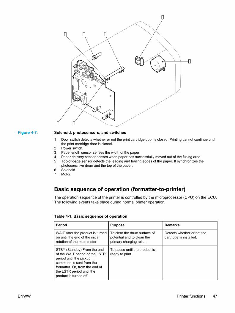
➁
➂ ➃
➀
➄
➅
➆
Figure 4-7. Solenoid, photosensors, and switches1 Door switch detects whether or not the print cartridge door is closed. Printing cannot continue until
the print cartridge door is closed.2 Power switch.3 Paper-width sensor senses the width of the paper.4 Paper delivery sensor senses when paper has successfully moved out of the fusing area.5 Top-of-page sensor detects the leading and trailing edges of the paper. It synchronizes the
photosensitive drum and the top of the paper.6 Solenoid.7 Motor.
Basic sequence of operation (formatter-to-printer)The operation sequence of the printer is controlled by the microprocessor (CPU) on the ECU.The following events take place during normal printer operation:
Table 4-1. Basic sequence of operation
Period Purpose Remarks
WAIT After the product is turnedon until the end of the initialrotation of the main motor.
To clear the drum surface ofpotential and to clean theprimary charging roller.
Detects whether or not thecartridge is installed.
STBY (Standby) From the endof the WAIT period or the LSTRperiod until the pickupcommand is sent from theformatter. Or, from the end ofthe LSTR period until theproduct is turned off.
To pause until the product isready to print.
ENWW Printer functions 47

Period Purpose Remarks
INTR (Initial Rotation Period)After the pickup command hasbeen sent from the formatteruntil the media reaches the top-of-page sensor (PS801).
To stabilize the photosensitivedrum sensitivity in preparationfor printing. Also to clean theprimary charging roller.
PRINT (Print) From the end ofthe initial rotation until theprimary voltage goes OFF.
To form images on thephotosensitive drum based onthe VIDEO signals (/VDO, VDO)sent from the formatter and totransfer the toner image ontothe media.
LSTR (Last Rotation Period)After the primary voltage goesOFF until the main motor stopsrotating.
To deliver the last page. Also toclean the primary chargingroller.
When the pickup command issent from the video controller,the printer enters the INTRperiod immediately after the endof the LSTR period.
48 Chapter 4 Operational overview ENWW

1 2 3 4 5 6 7 8 9 10 11 12 13 14 15 16 17 18 19 20
ST
BY
WA
ITS
TB
Y
Fix
ing
Hea
ter
(H70
1)
Prin
t Com
man
d
Sca
nner
Mot
or
Sca
nner
Rea
dy
Mai
n M
otor
(M
1)
Pic
k-up
Sol
enoi
d (S
L1)
Top
of P
aper
Sen
sor
(P
S80
1)
Pap
er D
eliv
ery
Sen
sor
(PS
803)
Prim
ary
Cha
rgin
g B
ias
(AC
)
Prim
ary
Cha
rgin
g B
ias
(DC
)
Dev
elop
ing
Bia
s (A
C)
Dev
elop
ing
Bia
s (D
C)
Tran
sfer
Cha
rgin
g B
ias
Lase
r D
iode
LAS
ER
BE
AM
sig
nal (
BD
)
INT
RP
RIN
TLS
TR
Abo
ut 1
.1
Abo
ut 1
.1A
bout
1.1
Abo
ut 0
.5A
bout
0.4
7
Abo
ut 0
.16
Abo
ut 0
.17
Abo
ut 0
.16
Abo
ut 0
.17
Abo
ut 0
.4A
bout
0.4
Abo
ut 2
.2
Abo
ut 0
.08
Abo
ut 0
.02
Abo
ut 0
.02
Abo
ut 1
.5
Abo
ut 0
.7A
bout
0.7
Abo
ut 1
.5
Abo
ut 3
.0
Abo
ut 0
.1A
bout
0.2
5
Abo
ut 0
.45
Abo
ut
0.65
Abo
ut 0
.6
Abo
ut 0
.2A
bout
0.2
Abo
ut 1
.5
Abo
ut 0
.1
Abo
ut 0
.99
Max
. 122
Abo
ut 0
.08
Abo
ut 0
.47
Max
. 1.5
1.8
Max
. 1.5
Abo
ut 0
.2
1.7
1.0
0.04
0.2
0.2M
ax. 3
.0
Pow
er S
witc
h O
N
SE
QU
EN
CE
100°C
Con
trol
Prin
t Tem
pera
ture
Con
trol
Bet
wee
n-sh
eets
Tem
pera
ture
Con
trol
Neg
ativ
e B
ias
Bet
wee
n-sh
eets
Bia
sP
rint B
ias
For
ced
emis
sion
(Uni
t:Sec
onds
)
Figure 4-8. Printer timing diagram
ENWW Printer functions 49

50 Chapter 4 Operational overview ENWW

Removal and replacement
This chapter describes the removal and replacement of field-replaceable units (FRUs) only.
Removal and replacement strategy........................................................................................52Required tools ................................................................................................................. 52Before performing service................................................................................................52Print cartridge .................................................................................................................. 52Differences between the series models............................................................................53Part removal order ........................................................................................................... 53
User-replaceable parts ........................................................................................................... 55Replacing the printer pickup roller ...................................................................................55Replacing the printer separation pad................................................................................57Replacing the main input tray (paper pick-up tray assembly)...........................................59Replacing the output tray extension (delivery tray assembly)..........................................60
Covers..................................................................................................................................... 61Right side cover................................................................................................................ 62Left side cover.................................................................................................................. 65Print cartridge access door, fuser cover, and rear panel..................................................65Front cover....................................................................................................................... 68
Internal assemblies................................................................................................................. 70Transfer roller assembly...................................................................................................70Engine power assembly...................................................................................................72Fuser (fixing) assembly....................................................................................................73Paper pickup assembly....................................................................................................75Engine control unit assembly............................................................................................76Laser scanner assembly...................................................................................................78
ENWW 51

Removal and replacement strategy
Detailed steps and images showing part removal are included here. Replacement isgenerally the reverse of removal. Occasionally, notes are included to provide directions fordifficult or critical replacement procedures.
WARNING! Remove the power cord before attempting to service the product. If this warning is notfollowed, severe injury can result as well as damage to the device. Certain functional checksduring troubleshooting must be performed with power supplied to the product. However, thepower supply should be disconnected during removal of any parts.
Sheet metal and plastic edges in the product can be sharp. Use caution when working on theproduct.
Never operate or service the printer with the protective cover removed from the laser scannerassembly. The reflected beam, although invisible, can damage your eyes.
CAUTION Some parts are sensitive to electrostatic discharge (ESD). Always perform service work at anESD-protected workstation.
To install a self-tapping screw, first turn it counterclockwise to align it with the existing threadpattern, then carefully turn it clockwise to tighten. Do not overtighten. If a self-tapping screw-hole becomes stripped, repair the screw-hole or replace the affected assembly.
Always remove the print cartridge before removing or replacing parts.
Required tools ● #2 Phillips-head screwdriver with magnetic tip
● Small flatblade screwdriver
● Needle-nose pliers
● ESD mat
CAUTION Do not use a PoziDrive screwdriver or any motorized screwdriver. These can damage screwsor screw threads on the product.
Before performing service● Remove all media.
● Unplug the power cable.
● Place the product on an ESD mat.
● Remove the input tray cover.
● Remove the print cartridge.
Print cartridge 1. Open the print cartridge access door on the top of the printer.
2. Remove the print cartridge.
CAUTION To prevent damage, do not expose the print cartridge to light. Cover it with a piece of paper.
52 Chapter 5 Removal and replacement ENWW

Figure 5-1. Removing the print cartridge
Differences between the series modelsWith the exception of the nameplate, there is no physical difference between the HP LaserJet1010 and HP LaserJet 1012 printers. The differences between these models are in firmwarefunctionality.
The HP LaserJet 1015 printer has a parallel port (callout 1, figure 5-2) in addition to the USBport.
1
Figure 5-2. HP LaserJet 1015 parallel port
Part removal order Use the following illustration to determine which parts must be removed before removingother parts.
ENWW Removal and replacement strategy 53

Product teardown tree
Right Side CoverTransfer Roller
Front CoverAssembly
Rear PanelAssembly
START
Engine PowerAssembly
Fuser (fixing)
Left Side Cover
Paper Pick-up
Customer Replaceables:-Delivery tray assy.-Paper pick-up tray assy.-Pick roller-Separation pad
ECU Assembly
Laser ScannerAssemblyAssembly
Assembly
Figure 5-3. Product teardown tree
54 Chapter 5 Removal and replacement ENWW

User-replaceable parts
To order a new pickup roller or separation pad, go to http://partsdirect.hp.com.
Replacing the printer pickup rollerIf the printer regularly misfeeds (no media feeds through) and cleaning the pickup roller doesnot fix it, replace the pickup roller.
CAUTION Failure to complete all the steps in this procedure might damage the product.
1. Turn off the printer, unplug the power cord, and wait for the printer to cool.
2. Open the print cartridge door, and remove the print cartridge.
3. Locate the pickup roller.
ENWW User-replaceable parts 55

4. Gently release the small, white tabs on each side of the pickup roller by pushing themaway from the roller, and then rotate the pickup roller toward the front.
CAUTION Use gentle pressure to release the small white tabs to avoid breaking them.
5. Gently pull the pickup roller up and out.
6. Position the new pickup roller in the slot of the previous pickup roller.
Note Circular and rectangular pegs on each side prevent you from incorrectly positioning thepickup roller.
7. Rotate the top of the new pickup roller into position until the white tabs on each side ofthe roller snap the roller into place.
56 Chapter 5 Removal and replacement ENWW

8. Reinstall the print cartridge and close the print cartridge door.
9. Plug in the printer, and turn it on.
Replacing the printer separation padIf the printer grabs more than one page at a time, you might have to replace the printerseparation pad. Recurring feed problems indicate that the printer separation pad is worn.
Note Before you change the separation pad, clean the pickup roller. See Chapter 4 forinstructions.
ENWW User-replaceable parts 57

Note The following procedure requires a #2 Phillips-head screwdriver.
1. Turn off the printer, unplug the power cord, and wait for the printer to cool.
2. At the back of the printer, unscrew the two screws holding the separation pad in place.
3. Remove the separation pad.
58 Chapter 5 Removal and replacement ENWW

4. Insert the new separation pad, and screw it in place.
5. Plug the printer in, and turn it on.
Replacing the main input tray (paper pick-up tray assembly)If you break or damage the main input tray (also called the paper pick-up tray assembly), youcan replace it.
1. Carefully flex the main input tray just enough to release one side.
Note Take care not to break the hinge points.
2. Remove the main input tray.
ENWW User-replaceable parts 59
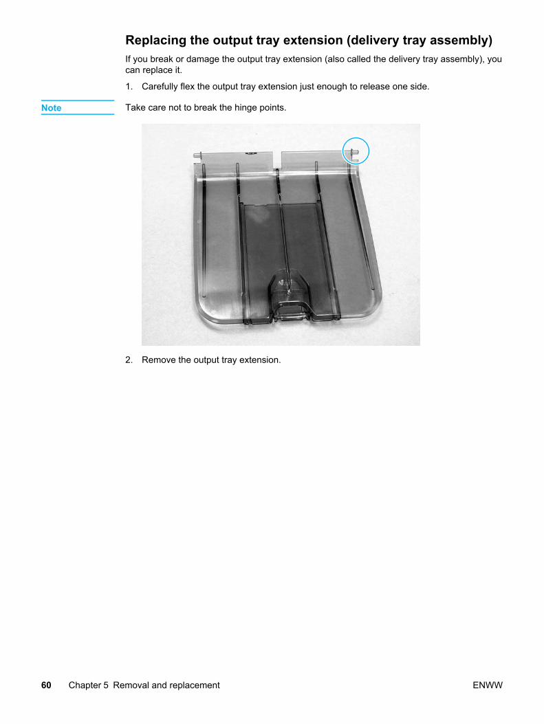
Replacing the output tray extension (delivery tray assembly)If you break or damage the output tray extension (also called the delivery tray assembly), youcan replace it.
1. Carefully flex the output tray extension just enough to release one side.
Note Take care not to break the hinge points.
2. Remove the output tray extension.
60 Chapter 5 Removal and replacement ENWW

Covers
Remove the covers to access the internal replaceable parts.
ENWW Covers 61
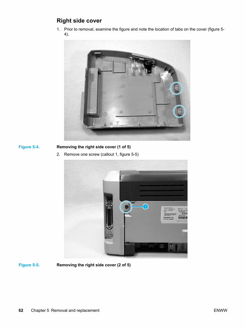
Right side cover1. Prior to removal, examine the figure and note the location of tabs on the cover (figure 5-
4).
Figure 5-4. Removing the right side cover (1 of 5)
2. Remove one screw (callout 1, figure 5-5)
1
Figure 5-5. Removing the right side cover (2 of 5)
62 Chapter 5 Removal and replacement ENWW
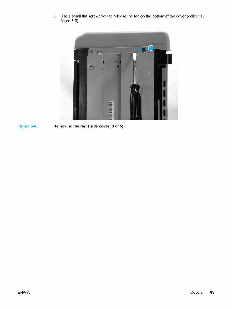
3. Use a small flat screwdriver to release the tab on the bottom of the cover (callout 1,figure 5-6).
1
Figure 5-6. Removing the right side cover (3 of 5)
ENWW Covers 63

4. Open the print cartridge door. Lift up at the arrow on the inside of the right side cover(callout 1, figure 5-7) to release a tab on top.
1
Figure 5-7. Removing the right side cover (4 of 5)
5. From the back, rotate the cover away from the printer and push forward.
Figure 5-8. Removing the right side cover (5 of 5)
64 Chapter 5 Removal and replacement ENWW

Left side cover1. Removing the left side cover is a similar procedure to removing the right side cover.
Refer to the steps and figures for removing the right side cover. Remove the screw onthe left side and be aware of the plastic tabs in the same places, but on the left side.
Print cartridge access door, fuser cover, and rear panel
Note This procedure removes the print cartridge access door (also called the face-down deliverytray), the fuser cover, and the metal rear panel. It is not necessary to take off the printcartridge access door first or to separate if from the fuser cover.
1. Remove the right side cover
2. Remove the left side cover.
3. Open the print cartridge access door.
4. Remove two screws from the top of the product (callout 1, figure 5-9).
1
Figure 5-9. Removing the rear panel (1 of 5)
ENWW Covers 65

5. Use needle-nosed pliers to release the plastic door link clip from the hinge arm on theprint cartridge access door (figure 5-10).
Figure 5-10. Removing the rear panel (2 of 5)
Note Reinsert the plastic door link clip or store it with the screws to prevent losing it.
Figure 5-11. Removing the rear panel (3 of 5)
66 Chapter 5 Removal and replacement ENWW

6. Remove one screw (callout 1, figure 5-12) from the back of the product.
1
Figure 5-12. Removing the rear panel (4 of 5)
7. The fuser cover and metal rear panel are interlocked with plastic tabs. Plastic tabs arealso securing the metal rear panel at the bottom. Lift up the fuser cover at the top andpull it slightly back. Lift the rear panel up off the tabs on the bottom. Both the fuser coverand the rear panel will come off together and are then easily separable.
Figure 5-13. Removing the rear panel (5 of 5)
ENWW Covers 67

Front cover1. Remove the left side cover.
2. Remove the right side cover.
3. Open the print cartridge door.
4. Prior to removal, examine figure 5-14 and note the locations of plastic tabs (circled) atthe top of the front cover.
Figure 5-14. Removing the front cover (1 of 3)
5. Using your index fingers or thumbs, pull down on the tabs on the bottom of both sides ofthe front cover (callout 1, figure 5-15).
1
Figure 5-15. Removing the front cover (2 of 3)
68 Chapter 5 Removal and replacement ENWW

6. With the bottom of the front cover released, pull up and back at the top while gentlyrocking to release all tabs at the top to remove the front cover.
Figure 5-16. Removing the front cover (3 of 3)
7. Remove the front cover.
Note When reassembling, make sure the tabs on the top of the front cover are in place and securethen press the bottom of the front cover into place.
ENWW Covers 69

Internal assemblies
This section describes the removal of internal assemblies. Replacement is accomplished byfollowing the removal steps in reverse. Reassembly notes are included where reversal ofremoval steps requires additional information.
Note When replacing internal assemblies, ensure that any component parts that are not providedwith the new assembly get transferred from the failed assembly to the new assembly. Forexample, sensor PCBs are not included with the fuser assembly or the paper pickupassembly. The sensor PCB from the failed assembly must be transferred to the newassembly.
Transfer roller assemblyBefore proceeding, make sure it is absolutely necessary to remove the transfer roller.
CAUTION Be very careful not to break the paper guide that is removed during replacement of thetransfer roller. This is not a replaceable part, so breaking it would require printer replacement.
CAUTION Do not touch the black sponge portion of the transfer roller.
1. Open the print cartridge door and remove the print cartridge.
2. Release the two tabs on the paper guide and rotate it up (figure 5-17).
Figure 5-17. Removing the transfer roller (1 of 3)
70 Chapter 5 Removal and replacement ENWW
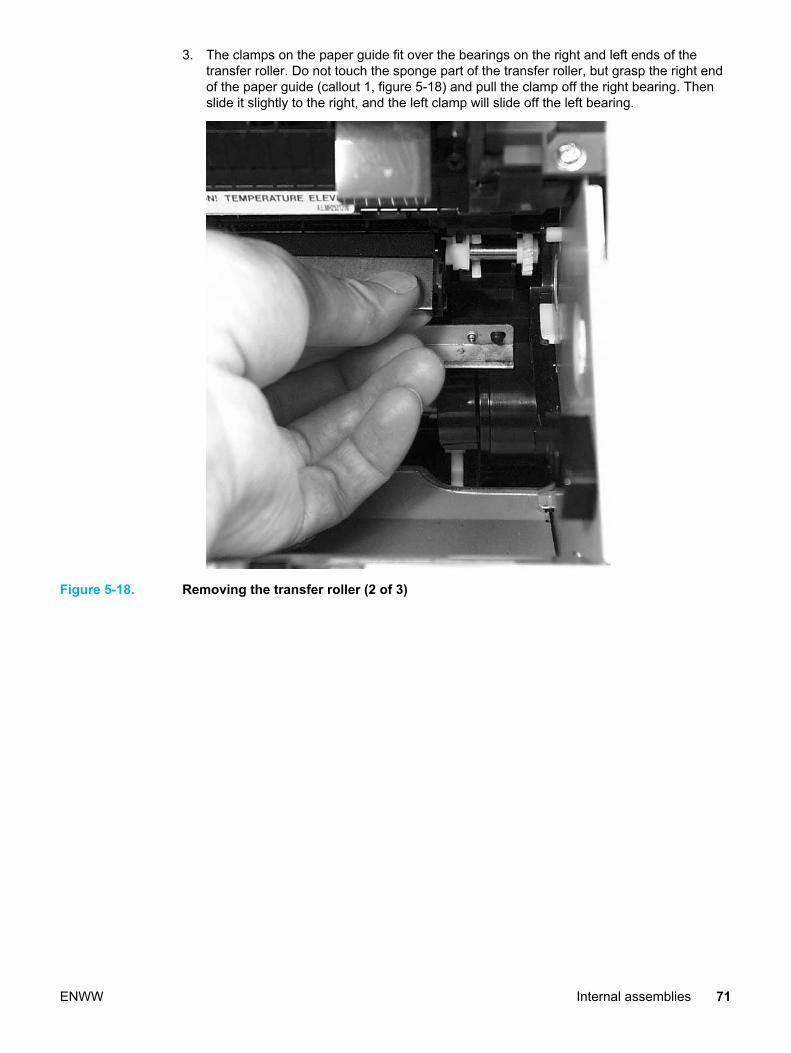
3. The clamps on the paper guide fit over the bearings on the right and left ends of thetransfer roller. Do not touch the sponge part of the transfer roller, but grasp the right endof the paper guide (callout 1, figure 5-18) and pull the clamp off the right bearing. Thenslide it slightly to the right, and the left clamp will slide off the left bearing.
Figure 5-18. Removing the transfer roller (2 of 3)
ENWW Internal assemblies 71

4. Use needle-nose pliers or your fingers to squeeze the two small tabs (figure 5-19) on thetransfer roller.
Figure 5-19. Removing the transfer roller (3 of 3)
5. Angle the transfer roller up holding onto the gear on the right side, slide it toward printer-right, and lift it out of the printer along with the transfer roller guide.
Note There is a small grounding spring under the right bearing of the transfer roller. Uponreassembly, position this spring correctly under the right bearing. Install the new transferroller, reversing the removal process. Then reinstall the paper guide by gently pressing thetwo ends onto the transfer roller bearings until the clamps snap into place. Rotate the paperguide down until the tabs on both ends engage.
Engine power assembly1. Remove the right side cover.
2. Remove the left side cover.
3. Remove the print cartridge access door.
4. Remove the rear panel.
5. Remove the front cover.
6. Disconnect the five cables (callout 1, figure 5-20) near the top of the power assembly.
72 Chapter 5 Removal and replacement ENWW
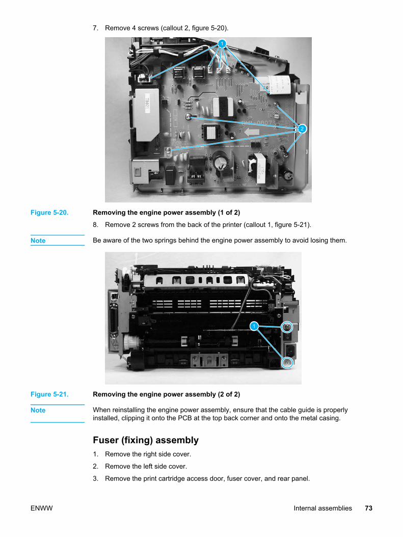
7. Remove 4 screws (callout 2, figure 5-20).
1
2
Figure 5-20. Removing the engine power assembly (1 of 2)
8. Remove 2 screws from the back of the printer (callout 1, figure 5-21).
Note Be aware of the two springs behind the engine power assembly to avoid losing them.
1
Figure 5-21. Removing the engine power assembly (2 of 2)
Note When reinstalling the engine power assembly, ensure that the cable guide is properlyinstalled, clipping it onto the PCB at the top back corner and onto the metal casing.
Fuser (fixing) assembly1. Remove the right side cover.
2. Remove the left side cover.
3. Remove the print cartridge access door, fuser cover, and rear panel.
ENWW Internal assemblies 73

4. Disconnect cables, as necessary, from near the top of the engine power assembly anddisconnect the large grounding wire from the back of the printer.
5. Unroute the wire harnesses, as necessary, to free up the fuser assembly.
6. Remove 3 screws (callout 1, figure 5-22). (Figure shows delivery sensor PCB removed,which is not necessary).
1
Figure 5-22. Removing the fuser (fixing) assembly
7. Lift the right (printer right) end of the fuser assembly and remove.
Note When replacing the fuser assembly, be sure to transfer the delivery sensor PCB from the oldfuser to the new one.
CAUTION A plastic tab on the left (printer-left) side of the fuser assembly fits into the sheet metal. Wheninstalling the fuser assembly, avoid breaking this tab.
74 Chapter 5 Removal and replacement ENWW
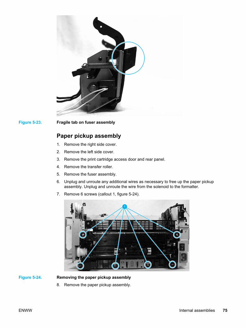
Figure 5-23. Fragile tab on fuser assembly
Paper pickup assembly1. Remove the right side cover.
2. Remove the left side cover.
3. Remove the print cartridge access door and rear panel.
4. Remove the transfer roller.
5. Remove the fuser assembly.
6. Unplug and unroute any additional wires as necessary to free up the paper pickupassembly. Unplug and unroute the wire from the solenoid to the formatter.
7. Remove 6 screws (callout 1, figure 5-24).
1
Figure 5-24. Removing the paper pickup assembly
8. Remove the paper pickup assembly.
ENWW Internal assemblies 75

Note When replacing the paper pickup assembly, be sure to transfer the sensor PCB and, ifnecessary, the separation pad assembly to the new paper pickup assembly.
Engine control unit assembly1. Remove the right side cover.
2. Disconnect the flat flexible (ribbon) cable from the formatter.
1
Figure 5-25. Removing the ECU assembly (1 of 5)
3. Remove the left side cover.
4. Disconnect the flat flexible (ribbon) cable from the engine power assembly.
1
Figure 5-26. Removing the ECU assembly (2 of 5)
76 Chapter 5 Removal and replacement ENWW

5. Open the print cartridge access door.
6. Remove the front cover.
7. Remove four screws (callout 1, figure 5-27).
1
Figure 5-27. Removing the ECU assembly (3 of 5)
8. Lift the ECU cover up just enough to free it and tilt it back as far as it will easily go.
9. Two sheet metal hook hinges (one on each side) secure the cover.
Figure 5-28. Removing the ECU assembly (4 of 5)
10. Push both hooks free with a screwdriver to remove the ECU cover.
ENWW Internal assemblies 77

11. Disconnect one ribbon cable and the connector to the step motor (callout 1, figure 5-29).Remove one screw (callout 2, figure 5-29). Remove the plastic retaining clip from theformatter ribbon cable and loosen the tape (callout 3, figure 5-29). As you are removingthe ECU, unplug the additional connector going to the laser scanner assembly.
1
2
3
Figure 5-29. Removing the ECU assembly (5 of 5)
12. As you are removing the ECU, unplug one additional connector going from the ECU PCBto the laser scanner assembly.
Note When reinstalling the ECU metal casing, ensure that the laser scanner cover lever is properlyinserted through the plastic guide.
Laser scanner assembly1. Remove the right side cover.
2. Remove the left side cover.
3. Remove the front cover.
78 Chapter 5 Removal and replacement ENWW
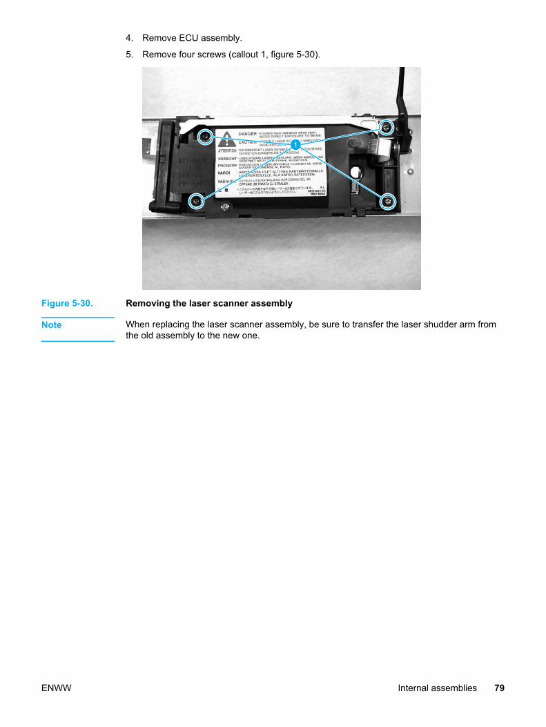
4. Remove ECU assembly.
5. Remove four screws (callout 1, figure 5-30).
1
Figure 5-30. Removing the laser scanner assembly
Note When replacing the laser scanner assembly, be sure to transfer the laser shudder arm fromthe old assembly to the new one.
ENWW Internal assemblies 79

80 Chapter 5 Removal and replacement ENWW

Troubleshooting
This chapter describes how to isolate and resolve printer problems, image problems, andmedia problems. Troubleshooting details are provided to resolve problems or to isolatereplaceable parts.
Basic troubleshooting.............................................................................................................. 82Control panel power-on functions...........................................................................................84
Power-on Functions: Time Ranges..................................................................................84Control Panel Pages............................................................................................................... 86
Control Panel Pages: Time Ranges.................................................................................86Control Panel Lights................................................................................................................ 87
Control Panel Light Patterns.............................................................................................87Fatal Errors....................................................................................................................... 91
Image troubleshooting............................................................................................................ 92Print cartridge problems...................................................................................................92Solving image-quality problems .......................................................................................92
Solving paper-feed problems.................................................................................................. 99Solving print paper-feed problems....................................................................................99
Functional checks................................................................................................................. 103Half self-test functional check.........................................................................................103Drum rotation functional check ......................................................................................105High-voltage contacts check...........................................................................................105
Troubleshooting tools ........................................................................................................... 107Repetitive image defect ruler..........................................................................................107Circuit diagram .............................................................................................................. 108
Solenoid, sensors, and switches...........................................................................................109
ENWW 81

Basic troubleshooting
Table 6-1. Basic troubleshooting
Issue Cause Solution
Did the printer turn on? No power due to failed powersource, cable, or switch.
1. Verify that the product isplugged in.
2. Verify that the power cableis functional and that thepower switch is on.
3. If all of these conditions arecorrect, replace the enginepower assembly.
Printer motor does not rotate. 1. Verify that the printcartridge access door isclosed.
2. Verify that the print path isclear. If clear, verify that theprint path paper sensorarms are free of debris andfunctional.
3. Verify that the cable fromthe ECU to the motor isconnected.
4. If all of these conditions arecorrect, replace the ECU.
5. If, after replacing the ECU,the printer motor still doesnot rotate, replace theengine power assembly.
6. If, after replacing the ECUand engine powerassembly, the printer motorstill does not rotate, replacethe printer.
Is the product ready?
The motor rotates, but the lightsare not on.
Formatter is damaged or has aloose connection.
Verify that the formatter cablesare properly connected. If allcables are undamaged andseated correctly but the problempersists, replace the printer.
Does the demo page print?
Print a demo page by pressingthe Go button when the printeris idle. Hold down the Go buttonfor more than 5 seconds to printa configuration page.
Media does not move smoothlythrough the paper path.
If the media is consistentlyjamming and the paper path isclear, replace either the paperpickup assembly or the fuser,depending on where it isjamming.
Poor print quality. See Image troubleshooting
82 Chapter 6 Troubleshooting ENWW

Issue Cause Solution
Is the software installedcorrectly?
Software is not installedcorrectly, or an error occurredduring software installation.
Uninstall and then reload theproduct software. Make sureyou use the correct installationprocedure and the correct portsetting.
Does the product print from thecomputer?
Connect the USB cable (orparallel if preferred with the HPLaserJet 1015) to the printerand the computer. Print a testpage from the printer propertiesbox or print from an applicationlike Notepad.
The cable is not connectedcorrectly.
Reconnect the cable.
An incorrect driver is selected. Select the proper driver.
Other devices are connected tothe parallel port.
Disconnect the other devicesand try again to print.
There is an LPT port driverproblem in Microsoft Windows.
Correct or reset the computer’sport settings.
ENWW Basic troubleshooting 83
Control panel power-on functions
Powering on the printer while pressing the Go button for varying amounts of time accessesimportant printer functionality for resetting the printer, resetting NVRAM, and performing self-tests. The general procedure for initiating a power-on function is as follows (refer to the tablefor specific time ranges for the desired function):
1. Power off the device.
2. Press and hold the Go button.
3. Power the device back on while holding the Go button for the amount of time specified inthe table below for the desired function.
4. Release the Go button.
Note Be sure that the light status is indicating the desired power-on function when the Go button isreleased. If the light status is different than desired when the Go button is released, start theprocedure at step 1.
Power-on Functions: Time Ranges
Power-on Function Time-Range(seconds)
Light Status Results and Notes
Cold reset Release Go 10 to 20seconds after power-up.
Attention: ON The lights begin cyclingfrom front to back. Thecold-reset process willrun until completionand the printer will goto the Ready state.
Continuous self-test Release Go 20 to 30seconds after power-up.
Attention: ON
Ready: ON
The Ready light blinksindicating that thedevice is in thecontinuous self-testmode. To terminate thecontinuous self-test,press Go.
NVMEM initialization Release Go 30 to 40seconds after power-up.
Attention: ON
Ready: ON
Go: ON
The lights begin cyclingfrom front to back. TheNVMEM initializationprocess will run untilcompletion and theprinter will go to theReady state.
Error report Release Go 40 to 50seconds after power-up.
Ready: ON
Go: ON
The printer producesan error report showingthe most recent error.
84 Chapter 6 Troubleshooting ENWW
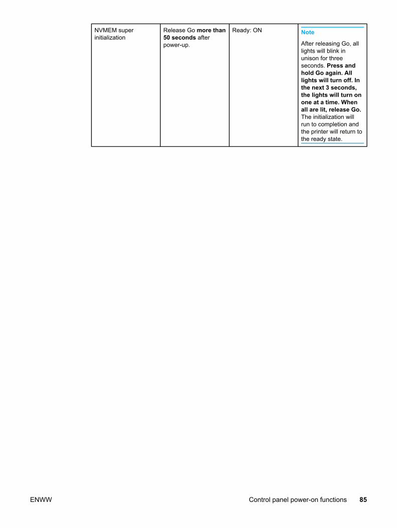
NVMEM superinitialization
Release Go more than50 seconds afterpower-up.
Ready: ON Note
After releasing Go, alllights will blink inunison for threeseconds. Press andhold Go again. Alllights will turn off. Inthe next 3 seconds,the lights will turn onone at a time. Whenall are lit, release Go.The initialization willrun to completion andthe printer will return tothe ready state.
ENWW Control panel power-on functions 85
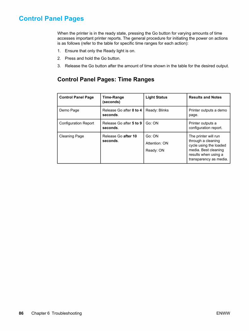
Control Panel Pages
When the printer is in the ready state, pressing the Go button for varying amounts of timeaccesses important printer reports. The general procedure for initiating the power on actionsis as follows (refer to the table for specific time ranges for each action):
1. Ensure that only the Ready light is on.
2. Press and hold the Go button.
3. Release the Go button after the amount of time shown in the table for the desired output.
Control Panel Pages: Time Ranges
Control Panel Page Time-Range(seconds)
Light Status Results and Notes
Demo Page Release Go after 0 to 4seconds.
Ready: Blinks Printer outputs a demopage.
Configuration Report Release Go after 5 to 9seconds.
Go: ON Printer outputs aconfiguration report.
Cleaning Page Release Go after 10seconds.
Go: ON
Attention: ON
Ready: ON
The printer will runthrough a cleaningcycle using the loadedmedia. Best cleaningresults when using atransparency as media.
86 Chapter 6 Troubleshooting ENWW

Control Panel Lights
The printer displays status and errors through patterns of the Go, Ready, and Attention lights.If any lights are blinking, the error is usually resolvable. In all cases:
1. If the error pattern occurs when printing, try pressing the Go button to continue.
2. Ensure that the print cartridge is properly installed and the print cartridge access door isclosed.
3. Cycle the printer power.
Control Panel Light PatternsThe lights on the printer, from back to front, are the Go, Ready, and Attention lights. Eachlight can be on solid, or blinking. All three can blink in sequence (cycling). In this document,the states of the lights are represented as follows:
Cycling
On
Off
Blinking
Ready
Attention
Go
Figure 6-1. Control panel lights legend
Printer Status Lights Description
Initialization/Startup
Ready
Attention
Go In the Initialization/StartupState, the lights cycle one afteranother in a front to backpattern (the "landing lights"pattern). Pressing buttons hasno effect.
Re-Config Initialization
Ready
Attention
Go When a power-on function isactivated (i.e., Cold-Reset orNVRAM-Initialization) the lightscycle as in the startup state.Pressing buttons has no effect.
Ready - The device is readywith no job activity
Go
Ready
Attention
In the Ready state, the Readylight is on and the Go andAttention lights are off. In thisstate, the printer has no errorsand is ready to receive data.Pressing Go prints a demopage.
ENWW Control Panel Lights 87

Printer Status Lights Description
Processing data - Device isprocessing or receiving data
Go
Ready
Attention
In the Data Processing state,the Ready light is blinking andthe Go and Attention lights areoff. Pressing Go cancels thecurrent job without printinganother non-picked page. Theprinter returns to the Readystate after the job has beencanceled.
Job Cancel
Ready
Attention
Go In the Job Cancel state, all thelights cycle. Pressing Go has noeffect. Once the job cancelprocess is complete, the printergoes to the Ready state.
88 Chapter 6 Troubleshooting ENWW
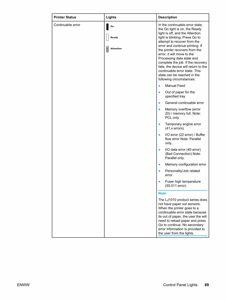
Printer Status Lights Description
Continuable error Go
Ready
Attention
In the continuable error state,the Go light is on, the Readylight is off, and the Attentionlight is blinking. Press Go toattempt to recover from theerror and continue printing. Ifthe printer recovers from theerror, it will move to theProcessing data state andcomplete the job. If the recoveryfails, the device will return to thecontinuable error state. Thisstate can be reached in thefollowing circumstances:
● Manual Feed
● Out of paper for thespecified tray
● General continuable error
● Memory overflow (error20) / memory full. Note:PCL only.
● Temporary engine error(41.x errors)
● I/O error (22 error) / Bufferflow error Note: Parallelonly.
● I/O data error (40 error)(Bad Connection) Note:Parallel only.
● Memory configuration error
● Personality/Job relatederror
● Fuser high temperature(50.011 error)
Note
The LJ1010 product series doesnot have paper out sensors.When the printer goes to acontinuable error state becauseits out of paper, the user the willneed to reload paper and pressGo to continue. No secondaryerror information is provided tothe user from the lights.
ENWW Control Panel Lights 89
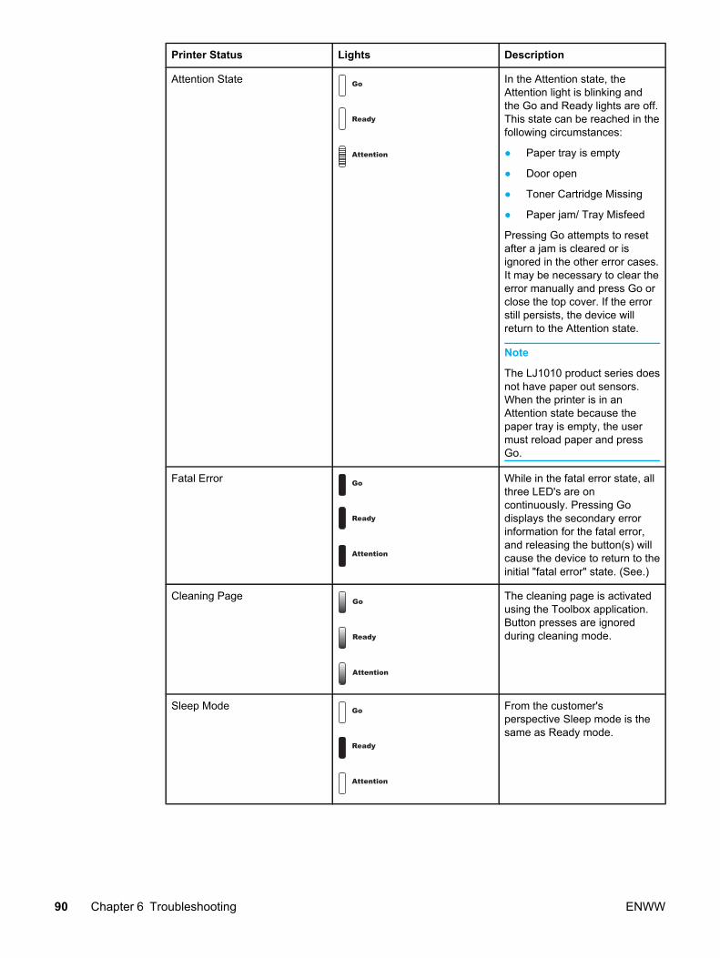
Printer Status Lights Description
Attention State Go
Ready
Attention
In the Attention state, theAttention light is blinking andthe Go and Ready lights are off.This state can be reached in thefollowing circumstances:
● Paper tray is empty
● Door open
● Toner Cartridge Missing
● Paper jam/ Tray Misfeed
Pressing Go attempts to resetafter a jam is cleared or isignored in the other error cases.It may be necessary to clear theerror manually and press Go orclose the top cover. If the errorstill persists, the device willreturn to the Attention state.
Note
The LJ1010 product series doesnot have paper out sensors.When the printer is in anAttention state because thepaper tray is empty, the usermust reload paper and pressGo.
Fatal Error Go
Ready
Attention
While in the fatal error state, allthree LED's are oncontinuously. Pressing Godisplays the secondary errorinformation for the fatal error,and releasing the button(s) willcause the device to return to theinitial "fatal error" state. (See.)
Cleaning Page
Ready
Attention
Go The cleaning page is activatedusing the Toolbox application.Button presses are ignoredduring cleaning mode.
Sleep Mode Go
Ready
Attention
From the customer'sperspective Sleep mode is thesame as Ready mode.
90 Chapter 6 Troubleshooting ENWW

Fatal ErrorsIf the printer displays all lights on solid and the error is not resolved by cycling the power,then a fatal error has occurred. The two identifiable errors are failed communication betweenthe formatter and the engine and a failed fuser. If neither of these are identified using thefollowing procedure, replace the printer.
1. Press and hold the Go button and the printer will display a secondary error pattern.
2. If the secondary error pattern is the Attention light on, the formatter and engine are notcommunicating.
● Check the ribbon cable between the formatter and ECU and all other connections.
● If error persists, replace the ECU.
● If error persists, replace the printer.
3. If the secondary error pattern is the Go and Ready lights on, the fuser (fixing assembly)has failed and must be replaced.
ENWW Control Panel Lights 91

Image troubleshooting
Print cartridge problems
Checking the print cartridgeImage formation defects are frequently the result of problems in the print cartridge. If there isany doubt, always replace the print cartridge before troubleshooting image defects.
Use the following checklist to make sure that the print cartridge is still operable.
□ Make sure that the print cartridge is installed properly and the shipping tape is removed.
□ Inspect the print cartridge for toner level.
□ Check the expiration date stamped on the print cartridge box.
□ Check the print cartridge to see if it has been disassembled or refilled.
□ Inspect the print cartridge to see if toner is leaking through worn seals.
□ Check the surface of the photosensitive drum in the cartridge to see if it has beendamaged or scratched. Touching the drum contaminates the photosensitive surface andcan cause spotting and image defects.
□ Blurred areas on printed pages indicate that the photosensitive drum in the cartridge hasbeen overexposed to light. Because overexposure to light causes permanent damage tothe photosensitive drum, the cartridge should be replaced.
Note A print cartridge weighs approximately 675 gm. (approx. 23.8 oz.) when it is full,approximately 600 gm. (approx. 21.2 oz.) when it first fades, and approximately 585 gm.(approx. 20.6 oz.) when it is empty.
To redistribute toner in the print cartridge
Before installing a new print cartridge or when toner begins to run low, redistribute the tonerby rotating the cartridge back and forth five or six times.
Solving image-quality problemsUse the following tables to help solve problems with printed pages.
If the problem occurs when printing, see Table 6-2. Solving print image-quality problems.
Also, see Table 6-3. Solving print paper-feed problems.
92 Chapter 6 Troubleshooting ENWW
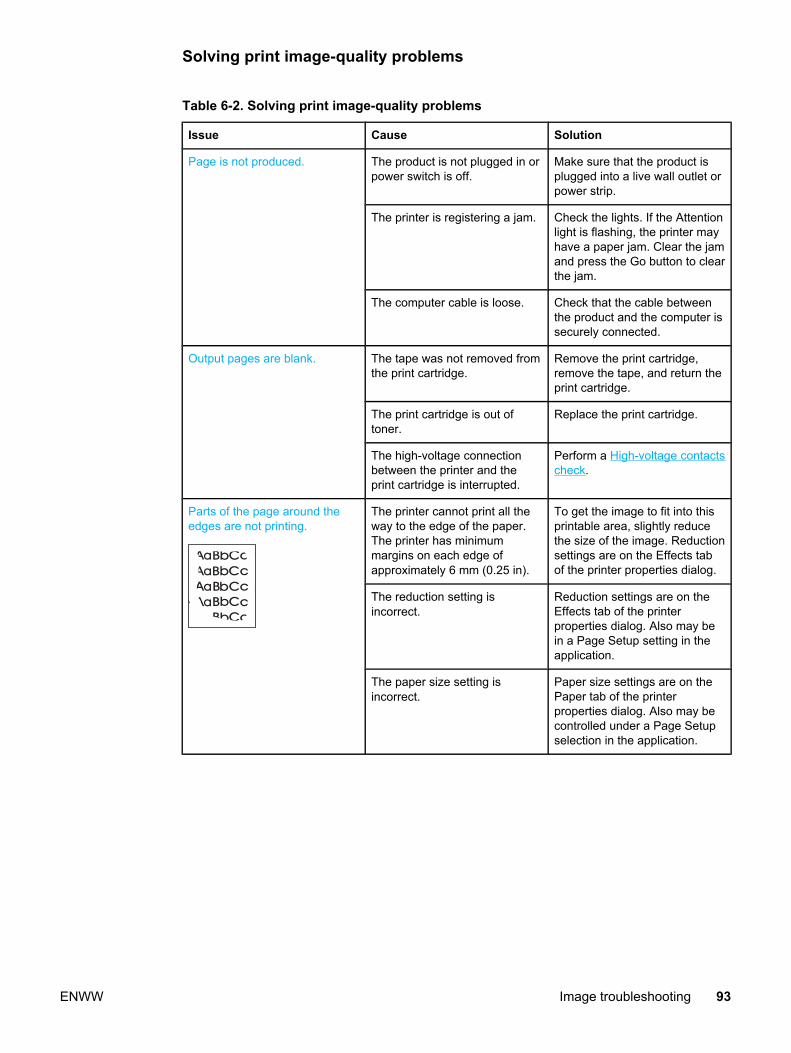
Solving print image-quality problems
Table 6-2. Solving print image-quality problems
Issue Cause Solution
Page is not produced. The product is not plugged in orpower switch is off.
Make sure that the product isplugged into a live wall outlet orpower strip.
The printer is registering a jam. Check the lights. If the Attentionlight is flashing, the printer mayhave a paper jam. Clear the jamand press the Go button to clearthe jam.
The computer cable is loose. Check that the cable betweenthe product and the computer issecurely connected.
Output pages are blank. The tape was not removed fromthe print cartridge.
Remove the print cartridge,remove the tape, and return theprint cartridge.
The print cartridge is out oftoner.
Replace the print cartridge.
The high-voltage connectionbetween the printer and theprint cartridge is interrupted.
Perform a High-voltage contactscheck.
Parts of the page around theedges are not printing.
The printer cannot print all theway to the edge of the paper.The printer has minimummargins on each edge ofapproximately 6 mm (0.25 in).
To get the image to fit into thisprintable area, slightly reducethe size of the image. Reductionsettings are on the Effects tabof the printer properties dialog.
The reduction setting isincorrect.
Reduction settings are on theEffects tab of the printerproperties dialog. Also may bein a Page Setup setting in theapplication.
The paper size setting isincorrect.
Paper size settings are on thePaper tab of the printerproperties dialog. Also may becontrolled under a Page Setupselection in the application.
ENWW Image troubleshooting 93

Issue Cause Solution
Random toner specks appearon the printed page.
.
The media you are using doesnot meet HP’s specifications(for example, it is too moist ortoo rough).
Make sure that the media meetsspecifications detailed in the HPLaserJet Printer Family PrintMedia Guide.
The print path needs to becleaned.
Clean the print path. (Seechapter 4.)
Characters are only partiallyprinted (also referred to asdropouts).
A single sheet of paper isdefective.
Try reprinting the job.
The print density needs to beadjusted.
Adjust the print density from thetoolbox utility (Settings tab).
The moisture content of thepaper is inconsistent, or thepaper has moist or wet spots onthe surface.
Make sure that the media meetsHP’s specifications.
The paper was damaged byinconsistent manufacturingprocesses.
Make sure that the media meetsspecifications detailed in the HPLaserJet Printer Family PrintMedia Guide.
EconoMode is selected in thesoftware.
Deselect EconoMode.
The wrong type of paper isselected in the printer propertiesdialog.
Select the correct media typeunder "Type is" (in the printerproperties dialog, on the Papertab).
The print cartridge is depletedor damaged.
Replace the print cartridge.
Vertical black lines appear onthe printed page.
The print cartridge is depletedor damaged.
Replace the print cartridge.
Rarely, the fuser is defective. Replace the fuser.
94 Chapter 6 Troubleshooting ENWW
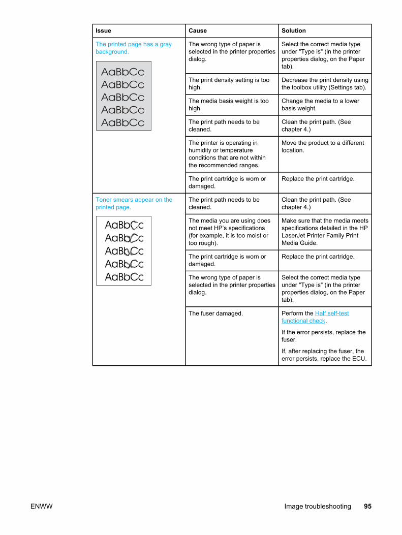
Issue Cause Solution
The printed page has a graybackground.
The wrong type of paper isselected in the printer propertiesdialog.
Select the correct media typeunder "Type is" (in the printerproperties dialog, on the Papertab).
The print density setting is toohigh.
Decrease the print density usingthe toolbox utility (Settings tab).
The media basis weight is toohigh.
Change the media to a lowerbasis weight.
The print path needs to becleaned.
Clean the print path. (Seechapter 4.)
The printer is operating inhumidity or temperatureconditions that are not withinthe recommended ranges.
Move the product to a differentlocation.
The print cartridge is worn ordamaged.
Replace the print cartridge.
Toner smears appear on theprinted page.
The print path needs to becleaned.
Clean the print path. (Seechapter 4.)
The media you are using doesnot meet HP’s specifications(for example, it is too moist ortoo rough).
Make sure that the media meetsspecifications detailed in the HPLaserJet Printer Family PrintMedia Guide.
The print cartridge is worn ordamaged.
Replace the print cartridge.
The wrong type of paper isselected in the printer propertiesdialog.
Select the correct media typeunder "Type is" (in the printerproperties dialog, on the Papertab).
The fuser damaged. Perform the Half self-testfunctional check.
If the error persists, replace thefuser.
If, after replacing the fuser, theerror persists, replace the ECU.
ENWW Image troubleshooting 95

Issue Cause Solution
The toner is loose, and it doesnot stay attached to the printedpage.
The media you are using doesnot meet HP’s specifications.(For example, it is too moist ortoo rough.)
Make sure that the media meetsspecifications detailed in the HPLaserJet Printer Family PrintMedia Guide.
The wrong type of paper isselected in the printer propertiesdialog.
Select the correct media typeunder "Type is" (in the printerproperties dialog, on the Papertab).
The power strip is not workingcorrectly or the AC power is notmeeting the specifiedrequirements.
Plug the product directly into anAC outlet. Ensure that thepower source is clean.
The printer is operating inhumidity or temperatureconditions that are not withinthe recommended ranges.
Move the product to a differentlocation.
The fuser is damaged. Perform a Half self-testfunctional check.
If the error persists, replace thefuser.
If, after replacing the fuser, theerror persists, replace theengine power assembly.
Repetitive vertical defectsappear on the printed page.
The internal parts have toner onthem.
If the defects occur on the backof the page, the problem willprobably correct itself after afew more printed pages.Otherwise, clean the printer.(See chapter 4.)
The wrong type of paper isselected in the printer propertiesdialog.
Select the correct media typeunder "Type is" (in the printerproperties dialog, on the Papertab).
If the repetitive mark occurs atequal distance between marks,either the print cartridge,transfer roller, paper pickupassembly, or fuser is damaged.
Use the defect ruler to identifythe spacing. Check theappropriate assembly andreplace if necessary. (Repetitiveimage defect ruler)
Characters are poorly formedand are producing hollowimages.
The wrong type of paper isselected in the printer propertiesdialog.
Select the correct media typeunder "Type is" (in the printerproperties dialog, on the Papertab).
The media is too slick or toothick.
Try a different media. Makesure that the media meetsspecifications detailed in the HPLaserJet Printer Family PrintMedia Guide.
96 Chapter 6 Troubleshooting ENWW
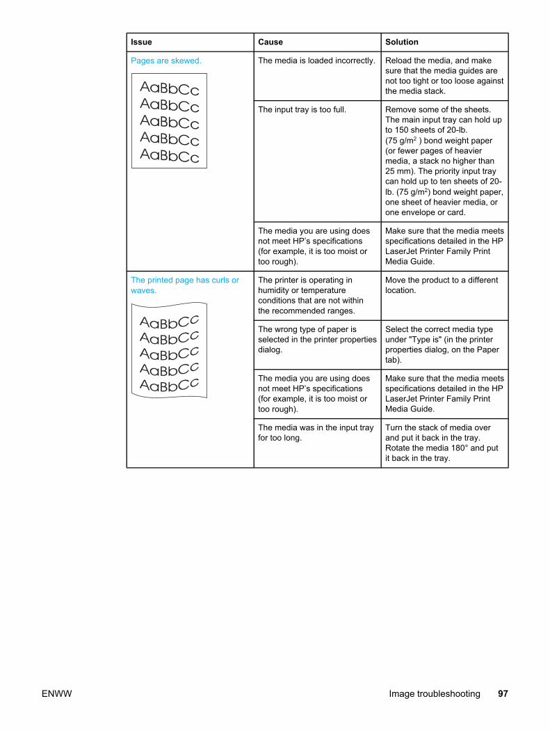
Issue Cause Solution
Pages are skewed. The media is loaded incorrectly. Reload the media, and makesure that the media guides arenot too tight or too loose againstthe media stack.
The input tray is too full. Remove some of the sheets.The main input tray can hold upto 150 sheets of 20-lb.(75 g/m2 ) bond weight paper(or fewer pages of heaviermedia, a stack no higher than25 mm). The priority input traycan hold up to ten sheets of 20-lb. (75 g/m2) bond weight paper,one sheet of heavier media, orone envelope or card.
The media you are using doesnot meet HP’s specifications(for example, it is too moist ortoo rough).
Make sure that the media meetsspecifications detailed in the HPLaserJet Printer Family PrintMedia Guide.
The printed page has curls orwaves.
The printer is operating inhumidity or temperatureconditions that are not withinthe recommended ranges.
Move the product to a differentlocation.
The wrong type of paper isselected in the printer propertiesdialog.
Select the correct media typeunder "Type is" (in the printerproperties dialog, on the Papertab).
The media you are using doesnot meet HP’s specifications(for example, it is too moist ortoo rough).
Make sure that the media meetsspecifications detailed in the HPLaserJet Printer Family PrintMedia Guide.
The media was in the input trayfor too long.
Turn the stack of media overand put it back in the tray.Rotate the media 180° and putit back in the tray.
ENWW Image troubleshooting 97
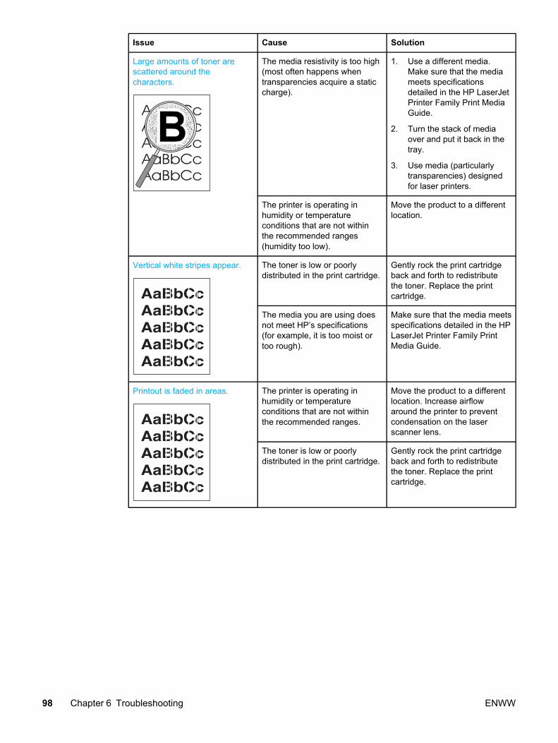
Issue Cause Solution
Large amounts of toner arescattered around thecharacters.
The media resistivity is too high(most often happens whentransparencies acquire a staticcharge).
1. Use a different media.Make sure that the mediameets specificationsdetailed in the HP LaserJetPrinter Family Print MediaGuide.
2. Turn the stack of mediaover and put it back in thetray.
3. Use media (particularlytransparencies) designedfor laser printers.
The printer is operating inhumidity or temperatureconditions that are not withinthe recommended ranges(humidity too low).
Move the product to a differentlocation.
Vertical white stripes appear. The toner is low or poorlydistributed in the print cartridge.
Gently rock the print cartridgeback and forth to redistributethe toner. Replace the printcartridge.
The media you are using doesnot meet HP’s specifications(for example, it is too moist ortoo rough).
Make sure that the media meetsspecifications detailed in the HPLaserJet Printer Family PrintMedia Guide.
Printout is faded in areas. The printer is operating inhumidity or temperatureconditions that are not withinthe recommended ranges.
Move the product to a differentlocation. Increase airflowaround the printer to preventcondensation on the laserscanner lens.
The toner is low or poorlydistributed in the print cartridge.
Gently rock the print cartridgeback and forth to redistributethe toner. Replace the printcartridge.
98 Chapter 6 Troubleshooting ENWW

Solving paper-feed problems
Use the following table to solve problems related to moving paper or documents through theproduct.
Solving print paper-feed problems
Table 6-3. Solving print paper-feed problems
Issue Cause Solution
Pages are coming out curled orwrinkled.
Paper curl is inherent to thelaser printing processes, andoccurs when paper is subjectedto heat. Paper curl tends torelax as the paper cools whileresting on a flat surface.
Make sure that the media meetsspecifications detailed in thePrint Media Guide for theHP LaserJet family. Reset thefuser mode to the default.
Paper is not stored properly. Whenever possible, store paperin its sealed ream at roomtemperature.
The media is too long for theprinter output bin.
Use the long media extension.
The printer is operating inhumidity or temperatureconditions that are not withinthe recommended ranges.
Move the product to a differentlocation.
The wrong type of paper isselected in the printer propertiesdialog.
Select the correct media typeunder "Type is" (in the printerproperties dialog, on the Papertab).
The media you are using doesnot meet HP’s specifications(for example, it is too moist ortoo rough).
Make sure that the media meetsspecifications detailed in the HPLaserJet Printer Family PrintMedia Guide.
The media was in the input trayfor too long.
Turn the stack of media overand put it back in the tray.Rotate the media 180° and putit back in the tray.
ENWW Solving paper-feed problems 99

Issue Cause Solution
Print is misaligned on the page(skewed pages).
The media is loaded incorrectly. Reload the media, and makesure that the media guides arenot too tight or too loose againstthe media stack.
The input tray is too full. Remove some of the sheets.The main input tray can hold upto 150 sheets of 20-lb.(75 g/m2 ) bond weight paper(or fewer pages of heaviermedia, a stack no higher than25 mm). The priority input traycan hold up to ten sheets of 20-lb. (75 g/m2) bond weight paper,one sheet of heavier media, orone envelope or card.
The media you are using doesnot meet HP’s specifications(for example, it is too moist ortoo rough).
Make sure that the media meetsspecifications detailed in the HPLaserJet Printer Family PrintMedia Guide.
100 Chapter 6 Troubleshooting ENWW

Issue Cause Solution
The printer feeds multiplesheets or jams frequently fromthe main input tray or priorityinput tray.
Paper guides are not adjustedproperly or paper is not farenough forward.
Slide the guides against thesides of the stack in the maininput tray or the priority inputtray to center the paper. Makesure the guides are not adjustedtoo tightly.
Stack is not neat and alignedwell on all sides.
Remove paper, align stack, andreplace.
The main input tray is overfilled. Remove some of the sheets.The main input tray can hold upto 250 sheets of 20-lb.(75 g/m2 ) bond weight paper(less for heavier paper) or from20 to 30 envelopes.
The priority input tray isoverfilled.
Remove media or feed singlesheets. The priority input tray isdesigned for optimal feeding ofsingle sheets, especially whenheavier media is used. It canhold up to ten sheets of 20-lb.(75 g/m2 ) bond weight paper(one sheet of heavier paper) orone envelope.
The paper was poorly cut by themanufacturer and is stickingtogether.
“Break” the ream of paper bycurving it into an upside-downu-shape; this can effectivelydecrease multifeeds. Also tryturning the paper around to feedthe opposite end first, or use adifferent type of paper.
The paper does not meet HP’sspecifications for print media.
Make sure that the media meetsspecifications detailed in thePrint Media Guide for theHP LaserJet family.
The output capacity wasexceeded in the paper outputbin.
Do not allow more than 125sheets of 20-lb. (75 g/m2) bondweight paper (less for heavierpaper) to fill the paper outputbin.
The pickup roller is dirty. Clean the pickup roller.
The pickup roller is damaged. Replace the pickup roller.
The separation pad isdamaged.
Replace the separation pad.
ENWW Solving paper-feed problems 101

Issue Cause Solution
The printer feeds multiplesheets or jams frequently fromthe main input tray or priorityinput tray (continued).
A sensor is not operatingproperly.
The chances of a sensor failingare very small. However, debrisaround the sensor arms maycause them to register a jam.There are only three sensors inthe printer (top of page, paperwidth, and delivery). Checkthem to ensure that the sensorarms can move freely. On therare occasion of a failed sensor,replace the printer.
102 Chapter 6 Troubleshooting ENWW

Functional checks
This section includes five functional checks for troubleshooting.
Half self-test functional checkThe print process can be subdivided into the following stages:
● image formation stage (charges the drum and writes a latent image to the drum with thelaser)
● development stage (forms a toner image on the drum)
● transfer stage (transfers the image to paper)
● cleaning stage (removes excess toner from the drum)
● fusing stage (applies heat and pressure to make the image on paper permanent)
To perform a half self-test checkThe purpose of the half self-test check is to begin the printing process and then interrupt itright in the middle. Examining the printer components at that point allows you to determinewhich stage in the print process is malfunctioning.
1. Press the Go button to print a demo (self-test) page.
2. Open the print cartridge access door the instant the leading edge of the paper exits theprinter.
3. Remove the print cartridge.
4. Open the print cartridge drum shield to view the drum surface. If a dark and distinct tonerimage is present on the drum surface, this shows that the first two functions of theelectrophotographic process are functioning (image formation and development). Anyfailure is occurring in the transfer or fusing stage.
To perform other checksIf there is no image on the photosensitive drum, perform these checks:
1. Make sure you removed the entire length of the sealing tape from the print cartridgebefore you installed the cartridge. If the tape is not removed then toner cannot get to thedrum.
2. Perform a drum rotation functional check to ensure that the drum is rotating. (See below.)
3. Perform a high-voltage contact check. (See below.)
If a transfer problem, replace the transfer roller. If a fuser problem, first check to make surethe three cables to the fuser are properly seated in the engine power assembly.
ENWW Functional checks 103

Figure 6-2. Check the fuser connections
1
Figure 6-3. Check the fuser connections
104 Chapter 6 Troubleshooting ENWW
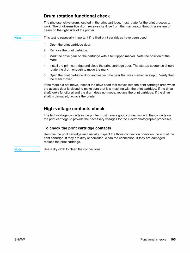
Drum rotation functional check The photosensitive drum, located in the print cartridge, must rotate for the print process towork. The photosensitive drum receives its drive from the main motor through a system ofgears on the right side of the printer.
Note This test is especially important if refilled print cartridges have been used.
1. Open the print cartridge door.
2. Remove the print cartridge.
3. Mark the drive gear on the cartridge with a felt-tipped marker. Note the position of themark.
4. Install the print cartridge and close the print cartridge door. The startup sequence shouldrotate the drum enough to move the mark.
5. Open the print cartridge door and inspect the gear that was marked in step 3. Verify thatthe mark moved.
If the mark did not move, inspect the drive shaft that moves into the print cartridge area whenthe access door is closed to make sure that it is meshing with the print cartridge. If the driveshaft looks functional and the drum does not move, replace the print cartridge. If the driveshaft is damaged, replace the printer.
High-voltage contacts checkThe high-voltage contacts in the printer must have a good connection with the contacts onthe print cartridge to provide the necessary voltages for the electrophotographic processes.
To check the print cartridge contacts Remove the print cartridge and visually inspect the three connection points on the end of theprint cartridge. If they are dirty or corroded, clean the connection. If they are damaged,replace the print cartridge.
Note Use a dry cloth to clean the connections.
ENWW Functional checks 105
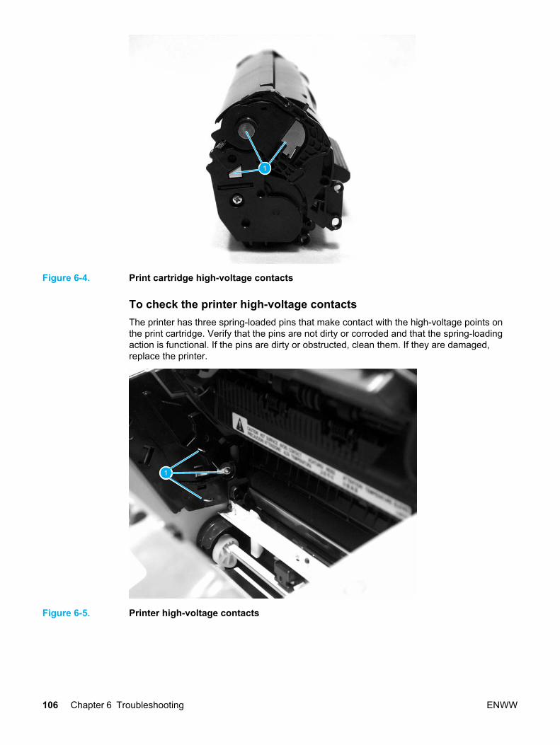
1
Figure 6-4. Print cartridge high-voltage contacts
To check the printer high-voltage contacts The printer has three spring-loaded pins that make contact with the high-voltage points onthe print cartridge. Verify that the pins are not dirty or corroded and that the spring-loadingaction is functional. If the pins are dirty or obstructed, clean them. If they are damaged,replace the printer.
1
Figure 6-5. Printer high-voltage contacts
106 Chapter 6 Troubleshooting ENWW

Troubleshooting tools
If the printer output has a consistent, repetitive defect, then use the following ruler to predictwhich part needs to be replaced based on the measured distance between the repetitions ofthe defect.
Repetitive image defect ruler
First occurrence of print defect (0.00 inches)�
Transfer roller 46.3 mm (1.82 inches)�
Print cartridge 37.7 mm (1.48 inches)�
Print cartridge 30.8 mm (1.21 inches)�
Paper pick-up assembly 55.2 mm (2.17 inches)�Fuser (Fixing assembly) 56.5 mm (2.22 inches)�
Fuser (Fixing assembly) 41.0 mm (1.61 inches)�
Print cartridge 76.3 mm (3.00 inches)�
Figure 6-6. Repetitive image defect ruler
ENWW Troubleshooting tools 107
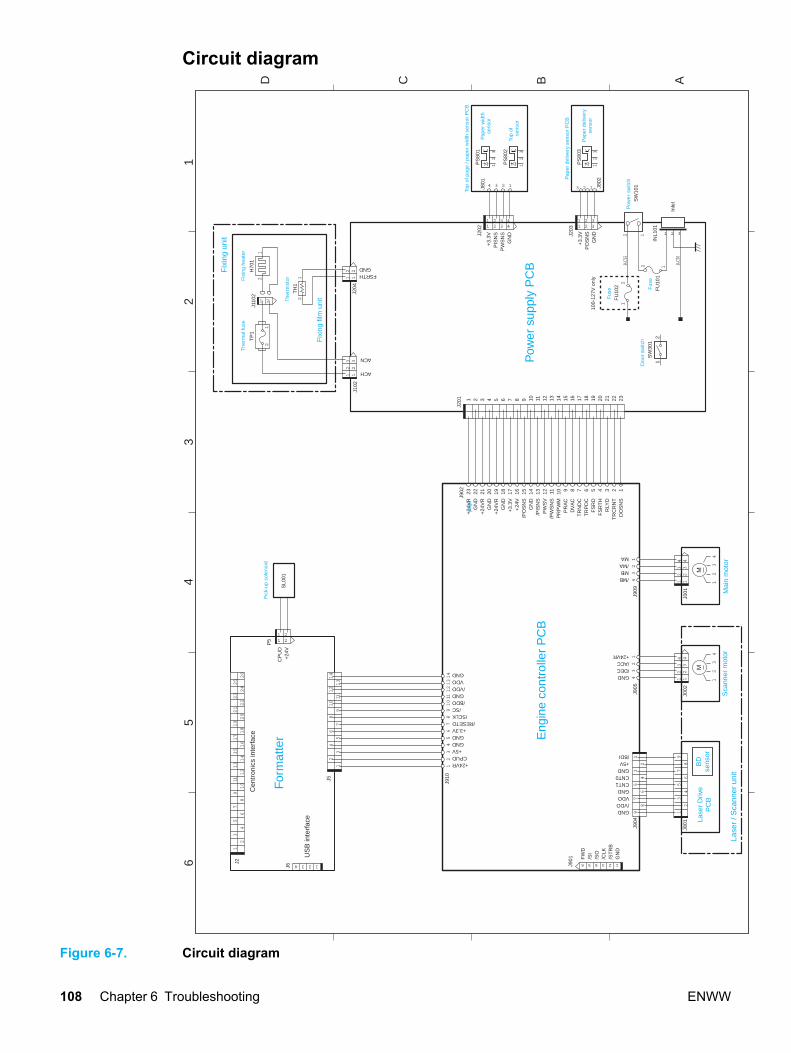
Circuit diagram
13 2465
43
21
D C B A
Pic
k-up
sol
enoi
d
SW
101
Pow
er
switc
h
M
13
24
Lase
r D
rive
PC
BB
Dse
nsor
Lase
r / S
cann
er u
nit
Doo
r sw
itch
SW
301
M
13
24
INL1
01F
U10
1F
use
FU
102
Fus
e
100-
127V
onl
y
24
68
13
57
9
21
TP
1
1 2
H70
1
21
TH
11
2
J110
2
12
12 FSRTH
GND
J102
J204
The
rmis
torFix
ing
heat
erT
herm
al fu
se
Fix
ing
film
uni
t
12
3
PS
803
1 321 32
Pap
er d
eliv
ery
sens
or
J203
3 12 J802
1 21 2
SL0
01
Pap
er d
eliv
ery
sens
or P
CB
CP
UD
+24
V
+3.
3VP
OS
NS
GN
D 1 32
Inle
t1
32
41
32
41
35
79
24
68
GND/VDOVDOGNDCNT1CNT0GND+5V/BDI
J002
J801
GND/DEC/ACC+24VR
J904
J905
US
B in
terf
ace
Sca
nner
mot
or
Fix
ing
unit
6 4 25 3 1
FW
D/S
I/S
O/C
LK/S
TR
BG
ND
J901
For
mat
ter E
ngin
e co
ntro
ller
PC
B
12
J201
Pow
er s
uppl
y P
CB
13
57
911
13
15
17
19
24
68
10
12
14
16
18
21
20
22
23
24
25
26
Cen
tron
ics
inte
rfac
e
J2
J902
13
21
32 ACH
ACN
1 32 41 32 4
4 23 1
12
3
PS
802
12
3
PS
801
Top
of
page
sens
or
Pap
er w
idth
sens
or
Top
of p
age
/ pap
er w
idth
sen
sor
PC
B
J801
+3.
3VP
ISN
SP
WS
NS
GN
DJ202
23 22 21 20 19 18 17 16 15 14 13 12 11 10 9 8 7 6 5 4 3 2 1
+24
VR
GN
D+
24V
RG
ND
+24
VR
GN
D+
3.3V
+24
V/P
OS
NS
GN
D/P
ISN
SP
WS
V/P
WS
NS
PR
PW
MP
RA
CD
VA
CT
RN
DC
TR
PD
CF
SR
DF
SR
TH
RLY
DT
RC
RN
TD
OS
NS
1 2 3 4 5 6 7 8 9 10 11 12 13 14 15 16 17 18 19 20 21 22 23
13
24
13
24
J001
/MBMB/MAMA
J909 Mai
n m
otor
42
31
42
31
13
57
911
13
24
68
10
12
14
13
57
911
13
24
68
10
12
14
+24VRCPUD
+5VGNDGND
+3.3V/RESETO
/SCLK/SC
/BDOGND/VDOVDOGND
J910
2 1
12 ACN
ACH
P5
J5
J6
21
Figure 6-7. Circuit diagram
108 Chapter 6 Troubleshooting ENWW
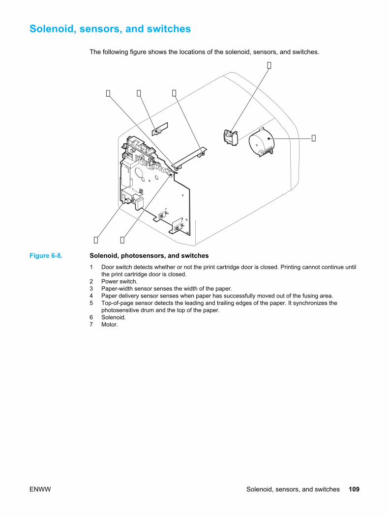
Solenoid, sensors, and switches
The following figure shows the locations of the solenoid, sensors, and switches.
➁
➂ ➃
➀
➄
➅
➆
Figure 6-8. Solenoid, photosensors, and switches1 Door switch detects whether or not the print cartridge door is closed. Printing cannot continue until
the print cartridge door is closed.2 Power switch.3 Paper-width sensor senses the width of the paper.4 Paper delivery sensor senses when paper has successfully moved out of the fusing area.5 Top-of-page sensor detects the leading and trailing edges of the paper. It synchronizes the
photosensitive drum and the top of the paper.6 Solenoid.7 Motor.
ENWW Solenoid, sensors, and switches 109

110 Chapter 6 Troubleshooting ENWW

Parts and diagrams
This chapter provides an exploded view showing the replaceable parts of the printer, tablesof replaceable parts, and links to other resources.
Ordering parts and supplies .................................................................................................112Parts .............................................................................................................................. 112Related documentation and software ............................................................................112Parts that wear ............................................................................................................. 112
Accessories and consumables ............................................................................................113Common hardware ........................................................................................................114How to use the parts lists and diagrams ........................................................................114
Field-replaceable units .........................................................................................................115
ENWW 111

Ordering parts and supplies
This section describes web resources for ordering parts and technical support as well asresources for ordering related documentation and software.
PartsOrder replacement parts from the following website: http://www.hp.com/ssg/parts/direct_order.html
Related documentation and softwareOrder documentation and software from the websites listed in Table 7-1. Technical supportwebsites:
Table 7-1. Technical support websites
HP Customer Care Online
Software drivers, support documentation, andanswers to frequently asked questions
http://www.hp.com/go/support
HP Technical Training (North America)
Classes and schedules
http://www.hp.com/go/resellertraining
Parts
Parts information
http://outfield.external.hp.com/spi/welcome.htm
Parts that wear The parts that wear on the product are listed in chapter 3 of this manual. Parts are availabledirectly from Hewlett-Packard at the following numbers:
● US: (800) 538-8787
● Canada: (800) 387-3154 in Toronto: (416) 671-8383
● United Kingdom: 0734-441212
● Germany: 0130-3322
Contact your local HP Parts Coordinator for other local phone numbers.
112 Chapter 7 Parts and diagrams ENWW

Accessories and consumables
Table 7-2. Accessories
Product name Description Product number Part number Exchangenumber
Print cartridges, cables, and HP Jetdirect Print Servers
Print cartridge 2,000 pagecartridge
N/A Q2612A
Cables andinterfaceaccessories
2-meterIEEE-1284parallel cable
N/A C2950A
Cables andinterfaceaccessories
3-meter IEEE-1284 parallelcable
N/A C2951A
Cables andinterfaceaccessories
2-meter USBcable
Q2460A 8121-0539
Cables andinterfaceaccessories
2-feet USB cable Q2460A 8121-0549
Cables andinterfaceaccessories
Power cord, US/Canada
Q2460A 8120-6812
Cables andinterfaceaccessories
Power cord,Europe
N/A 8120-6811
Cables andinterfaceaccessories
Power cord,Switzerland
N/A 8120-6815
Cables andinterfaceaccessories
Power cord, UK N/A 8120-6809
Cables andinterfaceaccessories
Power cord,Danish
N/A 8120-6814
Cables andinterfaceaccessories
Power cord, SA N/A 8120-6813
Cables andinterfaceaccessories
Power cord, Israel N/A 8120-6800
HP Jetdirect PrintServer
Model 500xEthernet/FastEthernet(10/100Base-TX)
J3265A J3265-61001
ENWW Accessories and consumables 113

Product name Description Product number Part number Exchangenumber
HP Jetdirect PrintServer
Model 500xToken Ring
J3264A J3264-61001
HP Jetdirect PrintServer
Model 300xEthernet/FastEthernet(10/100Base-TX)
J3263A J3263-61001
HP Jetdirect PrintServer
Model 170xEthernet (10Base-T)
J3258B J3258-61001
HP Jetdirect PrintServer
Model 310XEthernet/FastEthernet(10/100Base-TX)
J6038A J6038-60001
HP Jetdirect printserver
Model 310X N/A J6038-60001
HP Jetdirect PrintServer
Model 380xWireless Ethernet(802.11b)
J6061A J6061-61001
HP Jetdirect PrintServer
Model WP110Wireless Ethernet(802.11b)
J6062A J6062-61001
Toner cloth Ideal for wiping uptoner spills andcleaning theprinter
N/A 5090-3379
1(NOTE: If two parts are listed for one country or region, you can use either part regardless ofthe output rating.)
Common hardware The product uses common Phillips-head screws as fasteners.
How to use the parts lists and diagramsThe figures in this chapter illustrate the major subassemblies in the product. A table followsthe exploded assembly diagram. Each table lists the reference designator, the associatedpart number for the item, and a description of the part.
Parts that have no reference designator or part number are not field-replaceable units andcannot be ordered. Failure of a part that is not listed as replaceable and is not included with alisted field-replaceable unit requires replacement of the entire printer.
While looking for a part number, pay careful attention to the voltage listed in the descriptioncolumn to make sure that the part number selected is for the correct product model.
114 Chapter 7 Parts and diagrams ENWW

Field-replaceable units
1 2
Figure 7-1. All Models
Ref Description Part number Qty
1 Exchange-LJ1010-110V Printer Q2460-69001
1 Exchange-LJ1010-220V Printer Q2460-69002
1 Exchange-LJ1012-110V Printer Q2461-69001
1 Exchange-LJ1012-220V Printer Q2461-69002
2 Exchange-LJ1015-110V Printer Q2462-69001
2 Exchange-LJ1015-220V Printer Q2462-69002
2 Exchange-LJ1010-220V 3 Year Warranty Q2463-69001
ENWW Field-replaceable units 115

5
6
1
11
2
3
4
7
8
9
10
12
Figure 7-2. Exploded View: Field Replaceable Units
Table 7-3. Replaceable Assemblies
Ref Description Part number Qty
1 PAPER PICKUP TRAY ASS'Y RM1-0629-000 1
2 DELIVERY TRAY ASS'Y RM1-0659-000 1
116 Chapter 7 Parts and diagrams ENWW
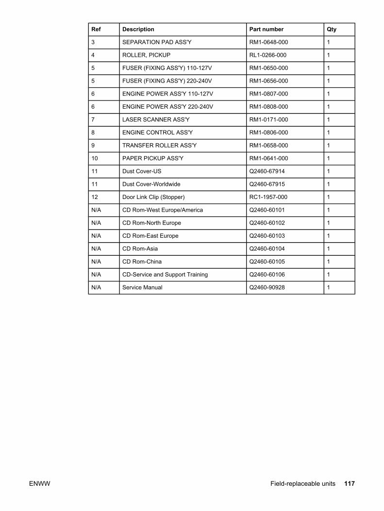
Ref Description Part number Qty
3 SEPARATION PAD ASS'Y RM1-0648-000 1
4 ROLLER, PICKUP RL1-0266-000 1
5 FUSER (FIXING ASS'Y) 110-127V RM1-0650-000 1
5 FUSER (FIXING ASS'Y) 220-240V RM1-0656-000 1
6 ENGINE POWER ASS'Y 110-127V RM1-0807-000 1
6 ENGINE POWER ASS'Y 220-240V RM1-0808-000 1
7 LASER SCANNER ASS'Y RM1-0171-000 1
8 ENGINE CONTROL ASS'Y RM1-0806-000 1
9 TRANSFER ROLLER ASS'Y RM1-0658-000 1
10 PAPER PICKUP ASS'Y RM1-0641-000 1
11 Dust Cover-US Q2460-67914 1
11 Dust Cover-Worldwide Q2460-67915 1
12 Door Link Clip (Stopper) RC1-1957-000 1
N/A CD Rom-West Europe/America Q2460-60101 1
N/A CD Rom-North Europe Q2460-60102 1
N/A CD Rom-East Europe Q2460-60103 1
N/A CD Rom-Asia Q2460-60104 1
N/A CD Rom-China Q2460-60105 1
N/A CD-Service and Support Training Q2460-60106 1
N/A Service Manual Q2460-90928 1
ENWW Field-replaceable units 117

Alphabetical parts list
Table 7-4. Alphabetical parts list
Description Part number Table and page
CD Rom-Asia Q2460-60104 Table 7-3 on page 117
CD Rom-China Q2460-60105 Table 7-3 on page 117
CD Rom-East Europe Q2460-60103 Table 7-3 on page 117
CD Rom-North Europe Q2460-60102 Table 7-3 on page 117
CD Rom-West Europe/America Q2460-60101 Table 7-3 on page 117
CD-Service and Support Training Q2460-60106 Table 7-3 on page 117
DELIVERY TRAY ASS'Y RM1-0659-000 Table 7-3 on page 116
Door Link Clip (Stopper) RC1-1957-000 Table 7-3 on page 117
Dust Cover-US Q2460-67914 Table 7-3 on page 117
Dust Cover-Worldwide Q2460-67915 Table 7-3 on page 117
ENGINE CONTROL ASS'Y RM1-0806-000 Table 7-3 on page 117
ENGINE POWER ASS'Y 110-127V RM1-0807-000 Table 7-3 on page 117
ENGINE POWER ASS'Y 220-240V RM1-0808-000 Table 7-3 on page 117
Exchange-LJ1010-110V Printer Q2460-69001 Table 7-2 on page 115
Exchange-LJ1010-220V 3 Year Warranty Q2463-69001 Table 7-2 on page 115
Exchange-LJ1010-220V Printer Q2460-69002 Table 7-2 on page 115
Exchange-LJ1012-110V Printer Q2461-69001 Table 7-2 on page 115
Exchange-LJ1012-220V Printer Q2461-69002 Table 7-2 on page 115
Exchange-LJ1015-110V Printer Q2462-69001 Table 7-2 on page 115
Exchange-LJ1015-220V Printer Q2462-69002 Table 7-2 on page 115
FUSER (FIXING ASS'Y) 110-127V RM1-0650-000 Table 7-3 on page 117
FUSER (FIXING ASS'Y) 220-240V RM1-0656-000 Table 7-3 on page 117
LASER SCANNER ASS'Y RM1-0171-000 Table 7-3 on page 117
PAPER PICKUP ASS'Y RM1-0641-000 Table 7-3 on page 117
PAPER PICKUP TRAY ASS'Y RM1-0629-000 Table 7-3 on page 116
ROLLER, PICKUP RL1-0266-000 Table 7-3 on page 117
SEPARATION PAD ASS'Y RM1-0648-000 Table 7-3 on page 117
Service Manual Q2460-90928 Table 7-3 on page 117
TRANSFER ROLLER ASS'Y RM1-0658-000 Table 7-3 on page 117
118 Chapter 7 Parts and diagrams ENWW
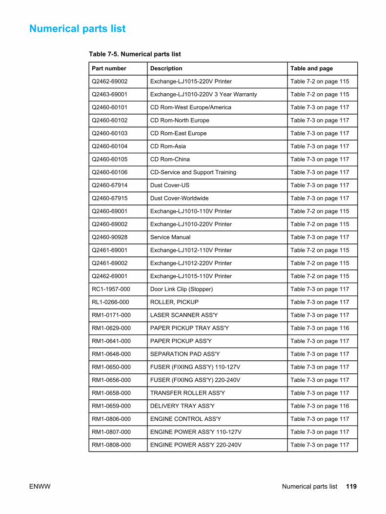
Numerical parts list
Table 7-5. Numerical parts list
Part number Description Table and page
Q2462-69002 Exchange-LJ1015-220V Printer Table 7-2 on page 115
Q2463-69001 Exchange-LJ1010-220V 3 Year Warranty Table 7-2 on page 115
Q2460-60101 CD Rom-West Europe/America Table 7-3 on page 117
Q2460-60102 CD Rom-North Europe Table 7-3 on page 117
Q2460-60103 CD Rom-East Europe Table 7-3 on page 117
Q2460-60104 CD Rom-Asia Table 7-3 on page 117
Q2460-60105 CD Rom-China Table 7-3 on page 117
Q2460-60106 CD-Service and Support Training Table 7-3 on page 117
Q2460-67914 Dust Cover-US Table 7-3 on page 117
Q2460-67915 Dust Cover-Worldwide Table 7-3 on page 117
Q2460-69001 Exchange-LJ1010-110V Printer Table 7-2 on page 115
Q2460-69002 Exchange-LJ1010-220V Printer Table 7-2 on page 115
Q2460-90928 Service Manual Table 7-3 on page 117
Q2461-69001 Exchange-LJ1012-110V Printer Table 7-2 on page 115
Q2461-69002 Exchange-LJ1012-220V Printer Table 7-2 on page 115
Q2462-69001 Exchange-LJ1015-110V Printer Table 7-2 on page 115
RC1-1957-000 Door Link Clip (Stopper) Table 7-3 on page 117
RL1-0266-000 ROLLER, PICKUP Table 7-3 on page 117
RM1-0171-000 LASER SCANNER ASS'Y Table 7-3 on page 117
RM1-0629-000 PAPER PICKUP TRAY ASS'Y Table 7-3 on page 116
RM1-0641-000 PAPER PICKUP ASS'Y Table 7-3 on page 117
RM1-0648-000 SEPARATION PAD ASS'Y Table 7-3 on page 117
RM1-0650-000 FUSER (FIXING ASS'Y) 110-127V Table 7-3 on page 117
RM1-0656-000 FUSER (FIXING ASS'Y) 220-240V Table 7-3 on page 117
RM1-0658-000 TRANSFER ROLLER ASS'Y Table 7-3 on page 117
RM1-0659-000 DELIVERY TRAY ASS'Y Table 7-3 on page 116
RM1-0806-000 ENGINE CONTROL ASS'Y Table 7-3 on page 117
RM1-0807-000 ENGINE POWER ASS'Y 110-127V Table 7-3 on page 117
RM1-0808-000 ENGINE POWER ASS'Y 220-240V Table 7-3 on page 117
ENWW Numerical parts list 119

120 Chapter 7 Parts and diagrams ENWW

Index
AAC bias 43AC power distribution 41accessories, ordering 113adding paper 22adhesive labels, printing 22alignment
troubleshooting 97, 100
Bback panel, removing 65background, gray 95base memory 5beam detect (BD) signal 43bidirectional communications 37, 38bin, output 5black dots, troubleshooting
printed pages 94, 98block diagram
printer 39block diagrams
image formation 43product functions 39
breaking paper reams 101buffer memory 38buttons
control panel 17
Ccables
interface, ordering 113card stock
specifications 20cards
printing 22Care Pack, HP 10cartridge
extending life of 38part number 113
cartridge area, cleaning 26cartridge door
locating 4cartridges
checking 92, 105drum rotation check 105life expectancies 24operations 43, 44
recycling 11refilled 11removing 52
central processing unit (CPU), formatter 37characters, misprinted 94, 96charging roller
operations 43power supply 42
checklistspreservice 52toner cartridge inspection 92troubleshooting 82
checksdrum rotation 105half-self-test 103high-voltage power supply 105
circuit capacity specifications 7circuit diagram 108circuitry, power system 41classes, HP Technical Training 112cleaning
high-voltage connection points 106high-voltage contacts 105pickup roller 27print cartridge area 26print path 25
cleaning stage, image formation process 44cleaning the product 25clip, removing
door link 65clipped pages, troubleshooting 93cloth, toner 114Coldfire processor 37communication operations 37, 38complex pages, printing 38conditioning stage, image formation process 43connection points
high-voltage power supply 106toner cartridge 105
consumablesordering 112
consumption, power 7Control Panel 37control panel
troubleshooting 82control panel components 17controller PCA.. See ECU
ENWW Index 121

country of origin, identifying 4coverage, printer 11covers, removing
front 68left side 65rear 65right side 62
CPU, formatter 37crooked pages, troubleshooting 97, 100curl, troubleshooting 97, 99custom-sized media, loading 22Customer Care Online 112cut-off edges 93
Ddata communication operations 37, 38DC bias 43DC Controller PCA.. See ECUDC power distribution 41Declaration of Conformity 12delay jams 46delivery sensor, paper (PS803)
feeding operations 45jam detection operations 46
delivery tray extensionreplacing 34, 60
delivery-delay jams 46delivery-stationary jams 46demo page 86density
operations 42troubleshooting 94
developing roller 42developing stage, image formation process 44differences between the models 53dimensions, product 16documentation
ordering 112doors
print cartridge 4dots per inch, maximum 5dots, troubleshooting
printed pages 94, 98dpi, maximum 5draft mode 38DRAM, formatter 37drivers, ordering 112dropouts, troubleshooting 94, 96drum
inspecting 92operations 43, 44rotation functional check 105
drum cleaning stage, image formation process 44duty cycle 5dynamic random access memory (DRAM), formatter
37
EEconoMode 38ECU
functions 39jam detection operations 46laser/scanner operations 40paper feeding operations 44removing 76
edges, not printing 93electrical specifications 7electrophotographic processes
operations 43testing 103
electrostatic discharge (ESD), precautions for 52element, heating
operations 44engine control unit
removing 76engine control unit.. See ECUengine power assembly
power system 41engine power assembly, removing 72Enhanced I/O 38envelopes
loading 22specifications for 20
environmental specifications 7, 16errors, control panel lights 87ESD (electrostatic discharge), precautions for 52exit rollers, fuser assembly 45exploded view
diagrams and part numbers 116extended warranty 10
Ffading white 98fading, troubleshooting 98fasteners, types of 114features
firmware 6hardware 3
feed assembly drive rollers 44feed system, paper 44feeding problems, troubleshooting
printer 99field replaceable units (FRUs)
procedures for replacing 51film, transparency
cleaning print path with 25loading 22
firmware features 6first page out 5fixing (fuser) assembly
removing 73flowchart, troubleshooting 82focusing lenses, operations 43formatter
122 Index ENWW

features 5operations 37
front cover, removing 68FRUs (field replaceable units)
procedures for replacing 51fuser (fixing) assembly
removing 73fuser assembly
exit rollers 45life expectancy 24operations 44temperature, adjusting 95, 96troubleshooting 94
fuser cover, removing 65fuses, overcurrent protection (F101, F102) 42fusing stage, image formation process 44
Ggray background, troubleshooting 95
Hhalf-self-test functional check 103hardware features 3hardware maintenance agreements 10heating element
operations 44height, product 16high-voltage power supply
connector assembly, checking 106operations 42testing 105
hingedoor link clip 65
HP Care Pack 10HP Customer Care Online 112HP Jetdirect print servers, ordering 113, 114HP Technical Training 112humidity
specifications 7troubleshooting 95, 96, 97, 98, 99
II/O, Enhanced 38idle mode, power consumption 7image density
troubleshooting 94voltage operations 42
image formation processoperations 43testing 103
image quality, troubleshootingprinted pages 93repetitive image defect ruler 107
input trayreplacing 33, 59
input trays.. See main input tray\inserting media 22
interface accessories, ordering 113INTR (Initial Rotation Period) 48isolated job settings 38
Jjams
detection operations 46paper input trays 101, 102
Jetdirect print servers, ordering 113, 114
Kkeys.. See buttons
Llabel, model and serial number 4labels
specifications for 19labels, printing 22languages, printer 38laser scanner assembly
precautions 52removing 78
laser/scanner assemblyoperations 40
latent electrostatic image 43leading edge
detection operations 44, 46LED's 87left side cover, removing 65length, product 16lenses, operations 43letterhead, loading 22life expectancies
extending toner cartridge 38recycling used print cartridges 11
lift plateoperations 44
lights, control panel 87lines, troubleshooting
printed pages 94loading media 22loose toner
troubleshooting 96, 97, 99, 100loose toner, troubleshooting 96LPT ports, troubleshooting 83LSTR (Last Rotation Period) 48
Mmachine screws 114main input tray
feeding operations 44feeding problems, troubleshooting 101, 102loading 22locating 4
main wiring diagram 108maintenance agreements 10manual feed tray.. See priority input tray
ENWW Index 123

manualsordering 112
margins, minimum 93media
common problems 19guidelines 19loading 22sizes 18specifications 18
memorybase 5buffer 38formatter 37
Memory Enhancement technology (MEt) 6, 38mirror operations 43misalignment
troubleshooting 97, 100misfeeds, frequent.. See feeding problems,
troubleshooting\model number 4models
differences 53motor
operations 40multifeeds
printer input trays 31, 57, 101, 102See also feeding problems, troubleshooting\
NNon-Volatile RAM.. See NVRAMnumbers, telephone 112NVRAM
operations 37
OOn/off switch
locating 5Online Customer Care, HP 112operating environment, specifications 7, 16order of
removing parts 53troubleshooting steps 82
ordering parts and supplies 112output bin
capacity 5output path
cleaning 25operations 45
output tray extension replacingreplacing 34, 60
overcurrent/overvoltage protection 42overhead transparencies
cleaning print path with 25loading 22
PPage Protect 38
pages per minute 7pages per month 5pages, control panel 86pages, demo 86paper
breaking reams 101common problems 19guidelines 19loading 22specifications 18storing 99
paper delivery sensor (PS803)feeding operations 45jam detection operations 46
paper feed problems, troubleshootingprinter 99
paper feed system 44paper input trays.. See main input tray\paper jams
detection operations 46printer input trays 101, 102
paper lift plateoperations 44
paper pathcleaning 25
paper pickup assemblyremoving 75
paper pickup roller.. See pickup rollerpaper size settings 93paper top sensor (PS801) 44, 46paper tray
replacing 33, 59paper-out sensor (PS201) 44, 46parallel cable, ordering 113Parallel interface 37parallel port
locating 5part removal order 53partial characters, troubleshooting 94, 96parts
ordering 112removing and replacing 52user-replaceable 29, 55
parts that wear 24path
feeding operations 44, 45print, cleaning 25
PCL (Printer Command Language) 38Phillips screwdrivers 52phone numbers, ordering supplies 112photosensitive drum
inspecting 92operations 43, 44rotation functional checks 105
photosensorslocating 46, 109
pickup delay jams 46
124 Index ENWW

pickup rollercleaning 27operations 44replacing 29, 55
pickup solenoid (SL001)locating 46, 109operations 44, 46
pickup stationary jam 46pins
high-voltage power supply 106PJL (Printer Job Language)
features 38pliers, required 52ports, troubleshooting
LPT 83power
specifications 7power cable, ordering 113power receptacle, locating 5power supplies
disconnecting 52engine power assembly 41testing high-voltage 105
power supply, removing 72power switch 5power-on functions, control panel 84PoziDriv screwdrivers, do not use 52ppm (pages per minute) 7precautions
laser scanner assembly 52power 52sharp edges 52
preprinted paper, loading 22preservice checklist 52pressure roller, operations 44primary charging roller
operations 43power supply 42
print cartridgeextending life of 38removing 52
print cartridge access door, removing 65print cartridge area, cleaning 26print cartridge door
locating 4print cartridge problems 92print cartridges
life expectancies 24operations 43recycling 11refilled 11
print densitytroubleshooting 94voltage operations 42
print pathcleaning 25feeding operations 44, 45
PRINT period 48print quality, troubleshooting 93print servers, ordering 113, 114Printer Command Language (PCL) 38printer drivers, ordering 112Printer Job Language (PJL)
features 38printer pickup roller
cleaning 27operations 44replacing 29, 55
printer separation padlife expectancy 24operations 44replacing 31, 57
printingfeed problems 99loading media 22troubleshooting 83
priority feed slotlocating 4
priority input trayfeeding operations 44feeding problems, troubleshooting 101, 102loading 22
processor, formatter 37product
cleaning on or around 25production code 4
Qquality, troubleshooting
printed pages 93repetitive image defect ruler 107
RRAM
base 5formatter 37
reams, breaking 101rear panel, removing 65receptacle, power 5recycling print cartridges 11redistributing toner 92reduction settings 93refilled print cartridges 11removing
door link clip 65engine control unit assembly 76engine power assembly 72front cover 68fuser assembly 73laser scanner assembly 78left side cover 65paper pickup assembly 75power assembly 72print cartridge access door 65
ENWW Index 125

rear panel 65right side cover 62transfer roller assembly 70
removing parts 52, 53repetitive defects, troubleshooting 96, 107replacement intervals
consumables 24print cartridges 5recycling used print cartridges 11
replacement parts.. See partsreplacing parts 29, 52, 53, 55report, troubleshooting
control panel 84reports, troubleshooting
control panel 86residual paper jams 46Resolution Enhancement technology (REt) 6resolution, maximum 5revision level 4right side cover, removing 62ROM
base 5rotation
drum 105ruler, repetitive defect 107
Sscanning exposure stage, image formation process
43scatter, toner 98schedules, HP Technical Training 112screwdrivers, required 52screws
self-tapping 52types of 114
sensorslocating 46, 109paper feed system 44
separation padreplacing 31, 57
separation padslife expectancies 24operations 44
separation stage, image formation process 44sequence
removing parts 53troubleshooting steps 82
serial number 4settings
print job 38side media guides, locating 11
See also guidessignals, VIDEO 48size
margins, minimum 93printer 16
skew
printed pages, troubleshooting 97, 100smears
troubleshooting 95smears, toner 95software
installation, troubleshooting 83ordering 112
solenoid (SL001)locating 46, 109operations 44, 46
solid lights, control panel 87space requirements 16spare parts.. See partsspecial media
common problems 19specifications 19, 21
specificationsmedia 18
specks, toner 94, 98speed
data transfer 38printing 7processor 37
spotsprinted pages 94, 98troubleshooting 95
stagesimage formation 43, 103
statementsDeclaration of Conformity 12
static eliminator, operations 44stationary jams 46status information, relaying 37, 38STBY (Standby) period 47storage environment, specifications 7storing paper 99stripes, vertical white 98subpads
operations 44supplies, ordering 112support, technical 112switches
power 5
Tteardown tree 53technical support 112Technical Training 112telephone numbers, ordering supplies 112temperature
fuser settings 95, 96specifications 7storing paper 99
testsdrum rotation 105half-self functional check 103high-voltage power supply 105
126 Index ENWW

text, troubleshootingmisprinted 94, 96
timing diagram, general 49toner
cloth, ordering 114image formation operations 44loose, troubleshooting 96redistributing 92scattered, troubleshooting 98smears, troubleshooting 95specks, troubleshooting 94, 98waste cleaning operations 44
toner cartridgeextending life of 38part number 113removing 52
toner cartridgeschecking 92, 105drum rotation check 105operations 44
toner cartridges.. See print cartridgestools, required 52trailing edge, detection 46Training, HP Technical 112transfer roller
cleaning around 25operations 44power supply 42removing 70
transfer stage, image formation process 44transparencies
cleaning print path with 25loading 22specifications for 19
trays.. See main input tray\troubleshooting
control panel 82control panel error report 84control panel lights 87control panel pages 86loose toner 96, 97, 99, 100LPT ports 83printing 82, 83smears 95software installation 83
spots 95vertical white lines 98
troubleshooting steps 82two-way communications 37, 38
UUniversal Serial Bus.. See USBunplugging printer 52USB
cable, ordering 113interface 37
USB interface 37user-replaceable parts 29, 55
Vvacuums, cautions against 26ventilation requirements 16vertical defects, troubleshooting 96vertical lines, troubleshooting 94vertical white lines
troubleshooting 98vertical white stripes, troubleshooting 98VIDEO signals 48voltage
DC power supply 41high-voltage power supply 42overvoltage protection 42
WWAIT period 47warranty
extended 10refilled cartridges, impact on 11statement 9
waste toner receptacle 44wave, troubleshooting 97, 99websites 112weight
toner cartridge 92width, product 16wiring diagram 108wrapping jams 46wrinkled pages, troubleshooting 99writing stage, image formation process 43
ENWW Index 127

128 Index ENWW

APPENDIX A: STATUS, WARNINGS & ERRORS REFERENCE
Header A = Auto-Continuable C = Continuable LED Pattern Headers
G = Go LED R = Ready LED A = Attention LED Button Headers G = Go button LED Pattern Values C = Cycling B = Blinking S = Solid Button Values P = Single Press H = Hold
ENWW Appendix A 129

CP
Function Message Prompt A C LED
Pattern Button DESCRIPTION
STATUS MESSAGES G R A G The EWS has it own way of locking menus and giving the user
feedback if they try to access a locked menu Job Cancel Canceling...<jobname> C C C The user presses the Job Cancel button. The LEDs cycle. The
job is aborted. Power ON Checking Paper Path C C C At power up. Cycle through all LEDs. Only happens at power
up. Power ON Checking Printer C C C At power up. Cycle through all LEDs. Only happens at power
up. Cleaning Page Cleaning… C
C
C
LEDs cycle while page is being printed.
Clearing Event Log This will happen automatically during an NVRAM Init and a cold reset. No msg will be displayed. We may want this from the EWS in service mode to execute this. Then we will want to display this. (Since this command will be executed from EWS, we don’t need any LED feedback at the printer.)
Power ON Initializing C C C Cycle through LEDs. Occurs on: - power on - coming out of EDOS
NVRAM Init Initialize Permanent Stor.
C S C
C S S C
CS S S C
H
During a power up initialization the user will press [Go] and hold until <Go>, <Ready>, and <Attention> LEDs come on solid (> 20 seconds).
Printing Config Pages
Printing…Configuration S B
H Press [Go] button > 5 seconds. <Go> and <Ready> LEDs will go on. Once [Go] button is released, <Ready> LED is blinking. A supplies page will follow if applicable. Also available from EWS. A single cancel button press during printing will only cancel the config page and not the supplies status page because they are two separate jobs.
Printing Demo Pages
Printing…Demo B P Press [Go] button. <Ready> LED blinking. Also available from EWS.
Printing…Event Log B Trigger from EWS; <Ready> LED blinking. Printing…Font List B Trigger from EWS; <Ready> LED blinking. Processing Data Processing...<jobname> B <Ready> LED blinking. This message is up while the printer
is processing a current job but hasn’t begun to pick pages yet. Processing...<jobname>
From Tray XX B This message comes up for any job, once the printer starts to
pick paper. Printer READY Ready S <Ready> LED on solid. Cold Reset Resetting Factory
Settings C
C
C C
CS C
H
During power up press and hold [Go] (for >5 and < 15 seconds) until <Attention> LED come on solid. Cycle through LEDs once user has released the [Go] button and the Cold Reset is being performed.
Warming Up Maintain initializing string WARNING
MESSAGES
File sent without FF
DATA RECEIVED To print last page press [Go]
S
B
B P Continuable error – <Go> LED solid and <Attention> LED blinking. Press [Go] button.
OUT OF PAPER B TRAY XX EMPTY
[TYPE] [SIZE] No LED pattern. This is a warning only the EWS and possibly
SAS will see. ERROR MESSAGES Personality, Job Related Error
CHOSEN PERSONALITY NOT AVAILABLE
To continue press [Go]
X X S
B
B
P Continuable error - <Go> LED solid and <Attention blinking>. Press [Go] button. If auto-continue is not set to ON then the error is continuable and the user must press the [Go] button to continue.
Top cover is open
CLOSE TOP COVER B
Toner missing INSTALL TONER CARTRIDGE
Out of Paper LOAD TRAY XX [TYPE] [SIZE]
To use another tray, press [Go].
S F If a job is sent, the printer holds it and waits for the paper to be loaded; would be misleading to just have the blinking attention on; “paper out in selected tray” is documented as the attention with ability to continue light pattern in the User Guide
130 Appendix A ENWW
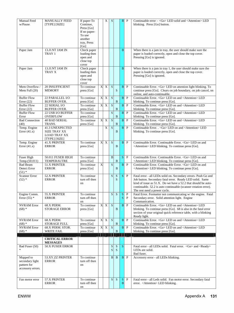
Manual Feed w/Pause
MANUALLY FEED [TYPE] [SIZE]
If paper-To Continue, Press [Go] If no paper-To use another tray, Press [Go]
X S B P Continuable error – <Go> LED solid and <Attention> LED blinking. Press [Go] button.
Paper Jam 13.JJ.NT JAM IN TRAY 1
Check paper loading then open and close top cover
B When there is a jam in tray, the user should make sure the paper is loaded correctly, open and close the top cover. Pressing [Go] is ignored.
Paper Jam 13.JJ.NT JAM IN TRAY X.
Check paper loading then open and close top cover
B When there is a jam in tray 1, the user should make sure the paper is loaded correctly, open and close the top cover. Pressing [Go] is ignored.
Mem Overflow / Mem Full (20)
20 INSUFFICIENT MEMORY.
To continue press [Go]
X X S
S
B
P Continuable Error. <Go> LED on attention light blinking. To continue press [Go]. Clears on job boundary, on job cancel, on online, and auto-continuable.
Buffer Flow Error (22)
22 PARALLEL I/O BUFFER OVER.
To continue press [Go]
X X S B
B P
Continuable Error. <Go> LED on and <Attention> LED blinking. To continue press [Go].
Buffer Flow Error (22)
22 SERIAL I/O BUFFER OVER.
To continue press [Go]
X X S
B
B P Continuable Error. <Go> LED on and <Attention> LED blinking. To continue press [Go].
Buffer Flow Error
22 USB I/O BUFFER OVERFLOW
To continue press [Go]
S
B
B P Continuable Error. <Go> LED on and <Attention> LED blinking. To continue press [Go].
Bad Connection (40)
40 BAD SERIAL TRANS.
To continue press [Go]
X X S
B
B
P
Continuable Error. <Go> LED on and <Attention> LED blinking. To continue press [Go].
Temp. Engine Error (41.x)
41.3 UNEXPECTED SIZE TRAY XX LOAD TRAY XX [TYPE] [SIZE]
X S B
B P
Continuable Error. . <Go> LED on and <Attention> LED blinking. To continue press [Go].
Temp. Engine Error (41.x)
41.X PRINTER ERROR
To continue press [Go]
X X S B
B P Continuable Error. Continuable Error. <Go> LED on and <Attention> LED blinking. To continue press [Go].
Fuser High Temp.(50.011)
50.011 FUSER HIGH TEMPERAUTRE
To continue press [Go]
B B
S
P Continuable Error. Continuable Error. <Go> LED on and <Attention> LED blinking. To continue press [Go].
Bad Beam Detect Error (51) *
51.X PRINTER ERROR
To continue press [Go]
X S
B
B P Continuable Error. Continuable Error. <Go> LED on and <Attention> LED blinking. To continue press [Go].
Scanner Error (52) *
52.X PRINTER ERROR
To continue turn off then on
S S S
S P Fatal error - all LEDs solid on. Secondary errors- Push Go and Job button. Secondary fatal error. Ready LED solid. Same kind of issue as 51.X. Do we have a 52.2 that should be auto-continuable. 52.2 is auto continuable (scanner rotation error). The rest need a power cycle.
Engine Comm. Error (55) *
55.X PRINTER ERROR
To continue turn off then on
S S S S
P P
Fatal Error. Formatter not communicating w/ the engine. Fatal Secondary error. Solid attention light. Engine Communication.
NVRAM Error (68) *
68.X PERM. STORAGE ERROR
To continue press [Go]
X X S B
B
P Continuable Error. <Go> LED on and <Attention> LED blinking. To continue press [Go]. 68 is also in the fatal error section of your original quick reference table, with a blinking Ready light.
NVRAM Error (68) *
68.X PERM. STORAGE FULL
To continue press [Go]
X X S B
B P Continuable Error. <Go> LED on and <Attention> LED blinking. To continue press [Go].
NVRAM Error (68) *
68.X PERM. STOR. WRITE FAIL
To continue press [Go]
X X S B
B P Continuable Error. <Go> LED on and <Attention> LED blinking. To continue press [Go].
CRITICAL ERROR
MESSAGES
Bad Fuser (50) *
50.X FUSER ERROR S S
S S
S
Fatal error - all LEDs solid. Fatal error. <Go> and <Ready> LEDs are solid. Bad fuser.
Mapped to secondary light pattern for accessory errors.
53.XY.ZZ PRINTER ERROR
To continue turn off then on
B B B P Accessory error - all LEDs blinking.
Fan motor error 57.X PRINTER ERROR
To continue turn off then on
S S S B
P Fatal error - all Leds solid. Fan motor error. Secondary fatal error. <Attention> LED blinking.
ENWW Appendix A 131
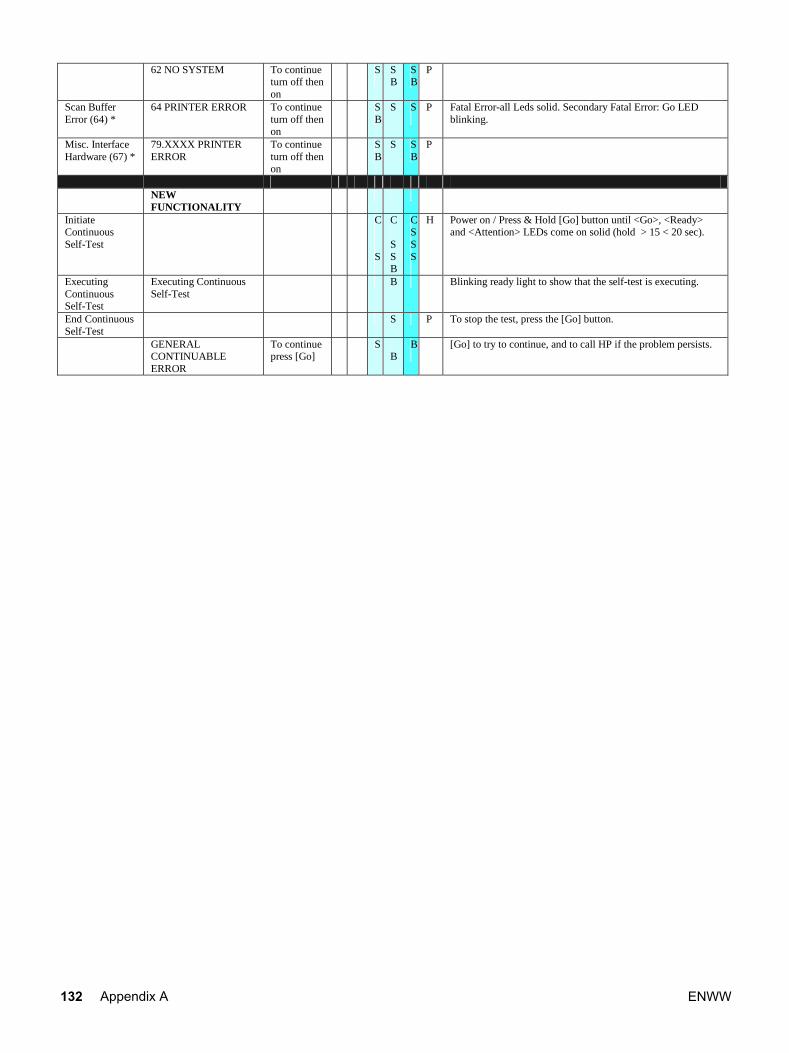
62 NO SYSTEM To continue turn off then on
S
S B
S B
P
Scan Buffer Error (64) *
64 PRINTER ERROR To continue turn off then on
S B
S S
P Fatal Error-all Leds solid. Secondary Fatal Error: Go LED blinking.
Misc. Interface Hardware (67) *
79.XXXX PRINTER ERROR
To continue turn off then on
S B
S S B
P
NEW
FUNCTIONALITY
Initiate Continuous Self-Test
C S
C S S B
CS S S
H Power on / Press & Hold [Go] button until <Go>, <Ready> and <Attention> LEDs come on solid (hold > 15 < 20 sec).
Executing Continuous Self-Test
Executing Continuous Self-Test
B Blinking ready light to show that the self-test is executing.
End Continuous Self-Test
S P To stop the test, press the [Go] button.
GENERAL CONTINUABLE ERROR
To continue press [Go]
S B
B
[Go] to try to continue, and to call HP if the problem persists.
132 Appendix A ENWW
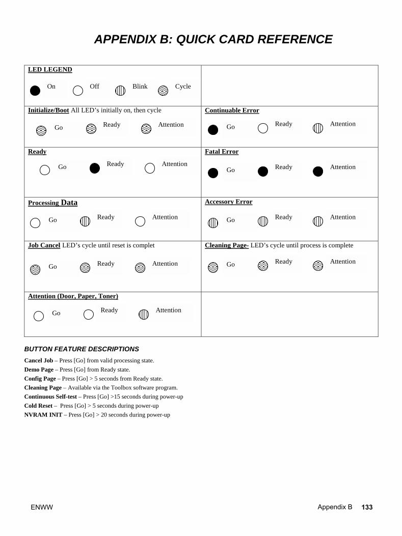
APPENDIX B: QUICK CARD REFERENCE
LED LEGEND
Initialize/Boot All LED’s initially on, then cycle
Continuable Error
Ready Fatal Error
Processing Data
Accessory Error
Job Cancel LED’s cycle until reset is complet Cleaning Page- LED’s cycle until process is complete
Attention (Door, Paper, Toner)
BUTTON FEATURE DESCRIPTIONS
Cancel Job – Press [Go] from valid processing state.
Demo Page – Press [Go] from Ready state.
Config Page – Press [Go] > 5 seconds from Ready state.
Cleaning Page – Available via the Toolbox software program.
Continuous Self-test – Press [Go] >15 seconds during power-up
Cold Reset – Press [Go] > 5 seconds during power-up NVRAM INIT – Press [Go] > 20 seconds during power-up
On Off Blink Cycle
Go Ready Attention
Go Ready Attention
Go Ready Attention
Go Ready Attention
Go Ready Attention
Go Ready Attention
Go Ready Attention
Go Ready Attention Go Ready Attention
ENWW Appendix B 133

134 Appendix B ENWW


*Q2460-90928**Q2460-90928*
Q2460-90928
www.hp.com
© 2003 Hewlett-Packard Development Company, L.P.


![HP LaserJet 1100h10032.2 TC RSTU/VWXY˙%& Z[ HP LaserJet 1100 2 34\] HP LaserJet 1100 ^2_](https://img.dokumen.tips/doc/110x75/60e4caee120602597e1c9852/hp-laserjet-2-tc-rstuvwxy-z-hp-laserjet-1100-2-34-hp-laserjet-1100-2.jpg)