Embed Size (px)
Citation preview
HP 8921A Cell Site Test Set HP-IB Programmer’s Guide
Firmware Versions: HP 8921A: A.15.00 and above
HP Part No. 08921-90031Printed in U. S. A.
December 1998
Rev. A
DUPLETXRX PREV TESTS
CONFIHELPMSSG HOLD PRINT
SCREEN CONTROL
LOCAL
ADRS
RECAL
SAVE
MEAS PRESE
INSTRUMENT STATE
DATA FUNCTIONS
INCRREF
INCR METER
INCR AVG
LO HI
CURSOR CON-
PUSH TO
CANCESHIFT
k1
k1’
k2
k2’
k3
k3’
k4
ASSIG
k5
RELEA
USER DATA
7 8 9
4 5 6
1 2 3
0 + _
ENTER
GHz
dB
MHz
%
kHz
s
Hz
ms
%
Ωppm
NO
ON/OFF
YES
MEMO
AUDIO INLOHI
! MAX! MAX
AUDIO SQUELCVOL-MIC/
MAX POWER 200 !
ANT INDUPLEX OUTRF IN/OUT
! MAX POWER
POWEOF O
1

Copyright © Hewlett-Packard Company 1997
Notice Information contained in this document is subject to change without notice.
All Rights Reserved. Reproduction, adaptation, or translation without prior written permission is prohibited, except as allowed under the copyright laws.
This material may be reproduced by or for the U.S. Government pursuant to the Copyright License under the clause at DFARS 52.227-7013 (APR 1988).
Hewlett-Packard CompanyLearning Products Department24001 E. MissionLiberty Lake, WA 99019-9599U.S.A.
2
Manufacture’s Declaration
This statement is provided to comply with the requirements of
the German Sound Emission Directive, from 18 January 1991.
This product has a sound pressure emission (at the operator
position) < 70 dB(A).
Sound Pressure Lp < 70 dB(A).
• At Operator Position.• Normal Operation.• According to ISO 7779:1988/EN 27779:1991 (Type Test).
Herstellerbescheinigung
Diese Information steht im Zusammenhang mit den Anforderungen der Maschinenlärminformationsverordnung vom 18 Januar 1991.
• Schalldruckpegel Lp < 70 dB(A).• Am Arbeitsplatz.• Normaler Betrieb.• Nach ISO 7779:1988/EN 27779:1991 (Typprüfung).
3

Safety Considerations GENERAL
This product and related documentation must be reviewed for familiarization with safety markings and instructions before operation.
This product is a Safety Class I instrument (provided with a protective earth terminal).
SAFETY EARTH GROUND
A uninterruptible safety earth ground must be provided from the main power source to the product input wiring terminals, power cord, or supplied power cord set.
CHASSIS GROUND TERMINAL
To prevent a potential shock hazard, always connect the rear-panel chassis ground terminal to earth ground when operating this instrument from a dc power source.
SAFETY SYMBOLS
Indicates instrument damage can occur if indicated operating limits are exceeded.
Indicates hazardous voltages.
Indicates earth (ground) terminal
WARNING A WARNING note denotes a hazard. It calls attention to a procedure, practice,or the like, which, if not correctly performed or adhered to, could result in per-sonal injury. Do not proceed beyond a WARNING sign until the indicated con-ditions are fully understood and met.
CAUTION A CAUTION note denotes a hazard. It calls attention to an operation proce-dure, practice, or the like, which, if not correctly performed or adhered to,could result in damage to or destruction of part or all of the product. Do notproceed beyond an CAUTION note until the indicated conditions are fully un-derstood and met.
!
4

Safety Considerations for this Instrument
WARNING: This product is a Safety Class 1 instrument (provided with a protective earthingground incorporated in the power cord) The mains plug shall only be inserted in asocket outlet provided with a protective earth contact. Any interruption of theprotective conductor inside or outside of the product is likely to make the productdangerous. Intentional interruption is prohibited.
Whenever it is likely that the protection has been impaired, the instrument must be made inoperative and be secured against any unintended operation.
If this instrument is to be energized via an autotransformer (for voltage reduction), make sure the common terminal is connected to the earth terminal of the power source.
If this product is not used as specified, the protection provided by the equipment could be impaired. This product must be used in a normal condition (in which all means for protection are intact) only.
No operator serviceable parts in this product. Refer servicing to qualified personnel. To prevent electrical shock, do not remove covers.
Servicing instructions are for use by qualified personnel only. To avoid electrical shock, do not perform any servicing unless you are qualified to do so.
The opening of covers or removal of parts is likely to expose dangerous voltages. Disconnect the product from all voltage sources while it is being opened.
Adjustments described in the manual are performed with power supplied to the instrument while protective covers are removed. Energy available at many points may, if contacted, result in personal injury.
The power cord is connected to internal capacitors that my remain live for 5 seconds after disconnecting the plug from its power supply.
For continued protection against fire hazard, replace the line fuse(s) only with 250 V fuse(s) or the same current rating and type (for example, normal blow or time delay). Do not use repaired fuses or short circuited fuseholders.
5

WARNING: Always use the three-prong ac power cord supplied with this product. Failure toensure adequate earth grounding by not using this cord may cause product damage.
This product is designed for use in Installation Category II and Pollution Degree 2 per IEC 1010 and IEC 664 respectively. For indoor use only.
This product has autoranging line voltage input, be sure the supply voltage is within the specified range.
To prevent electrical shock, disconnect instrument from mains (line) before cleaning. Use a dry cloth or one slightly dampened with water to clean the external case parts. Do not attempt to clean internally.
Ventilation Requirements: When installing the product in a cabinet, the convection into and out of the product must not be restricted. The ambient temperature (outside of the cabinet) must be less than the maximum operating temperature of the product by 4° C for every 100 watts dissipated in the cabinet. If the total power dissipated in the cabinet is greater than 800 watts, then forced convection must be used.
Product Markings CE - the CE mark is a registered trademark of the European Community. A CE mark accompanied by a year indicated the year the design was proven.
CSA - the CSA mark is a registered trademark of the Canadian Standards Association.
6
r
CERTIFICATION Hewlett-Packard Company certifies that this product met its published specifications at the time of shipment from the factory. Hewlett-Packard further certifies that its calibration measurements are traceable to the United States National Institute of Standards and Technology, to the extent allowed by the Institute’s calibration facility, and to the calibration facilities of otheInternational Standards Organization members
Hewett-Packard Warranty Statement for Commercial Products
HP Product: HP 8921A
Duration of Warranty: 1 Year
1. HP warrants HP hardware, accessories and supplies against defects in materials and workmanship for the period specified above. If HP receives notice of such defects during the warranty period, HP will, at its option, either repair or replace products which prove to be defective. Replacement products may be either new or like-new.
2 HP warrants that HP software will not fail to execute its programming instruc-tions, for the period specified above, due to defects in material and workmanship when properly installed and used. If HP receives notice of such defects during the warranty period, HP will replace software media which does not execute its pro-gramming instructions due to such defects.
3. HP does not warrant that the operation of HP products will be uninterrupted or error free. If HP is unable, within a reasonable time, to repair or replace any product to a condition as warranted, customer will be entitled to a refund of the purchase price upon prompt return of the product.
4 HP products may contain remanufactured parts equivalent to new in performance or may have been subject to incidental use.
5. The warranty period begins on the date of delivery or on the date of installation if installed by HP. If customer schedules or delays HP installation more than 30 days after delivery, warranty begins on the 31st day from delivery.
6 Warranty does not apply to defects resulting from (a) improper or inadequate maintenance or calibration, (b) software, interfacing, parts or supplies not supplied by HP, (c) unauthorized modification or misuse, (d) operation outside of the pub-lished environmental specifications for the product, or (e) improper site prepara-tion or maintenance.
7

7 TO THE EXTENT ALLOWED BY LOCAL LAW, THE ABOVE WARRAN-TIES ARE EXCLUSIVE AND NO OTHER WARRANTYOR CONDITION, WHETHER WRITTEN OR ORAL IS EXPRESSED OR IMPLIED AND HP SPECIFICALLY DISCLAIMS ANY IMPLIED WARRANTIES OR CONDI-TIONS OR MERCHANTABILITY, SATISFACTORY QUALITY, AND FIT-NESS FOR A PARTICULAR PURPOSE.
8 HP will be liable for damage to tangible property per incident up to the greater of $300,000 or the actual amount paid for the product that is the subject of the claim, and for damages for bodily injury or death, to the extent that all such damages are determined by a court of competent jurisdiction to have been directly caused by a defective HP product.
9. TO THE EXTENT ALLOWED BY LOCAL LAW, THE REMEDIES IN THIS WARRANTY STATEMENT ARE CUSTOMER’S SOLE AND EXCLUSIVE REMEDIES. EXCEPT AS INDICATED ABOVE, IN NO EVENT WILL HP OR ITS SUPPLIERS BE LIABLE FOR LOSS OF DATA OR FOR DIRECT, SPECIAL, INCIDENTAL, CONSEQUENTIAL (INCLUDING LOST PROFIT OR DATA), OR OTHER DAMAGE, WHETHER BASED IN CONTRACT, TORT, OR OTHERWISE.
FOR CONSUMER TRANSACTIONS IN AUSTRALIA AND NEW ZEALAND: THE WARRANTY TERMS CONTAINED IN THIS STATE-MENT, EXCEPT TO THE EXTENT LAWFULLY PERMITTED, DO NOT EXCLUDE RESTRICT OR MODIFY AND ARE IN ADDITION TO THE MANDATORY STATUTORY RIGHTS APPLICABLE TO THE SALE OF THIS PRODUCT TO YOU.
8
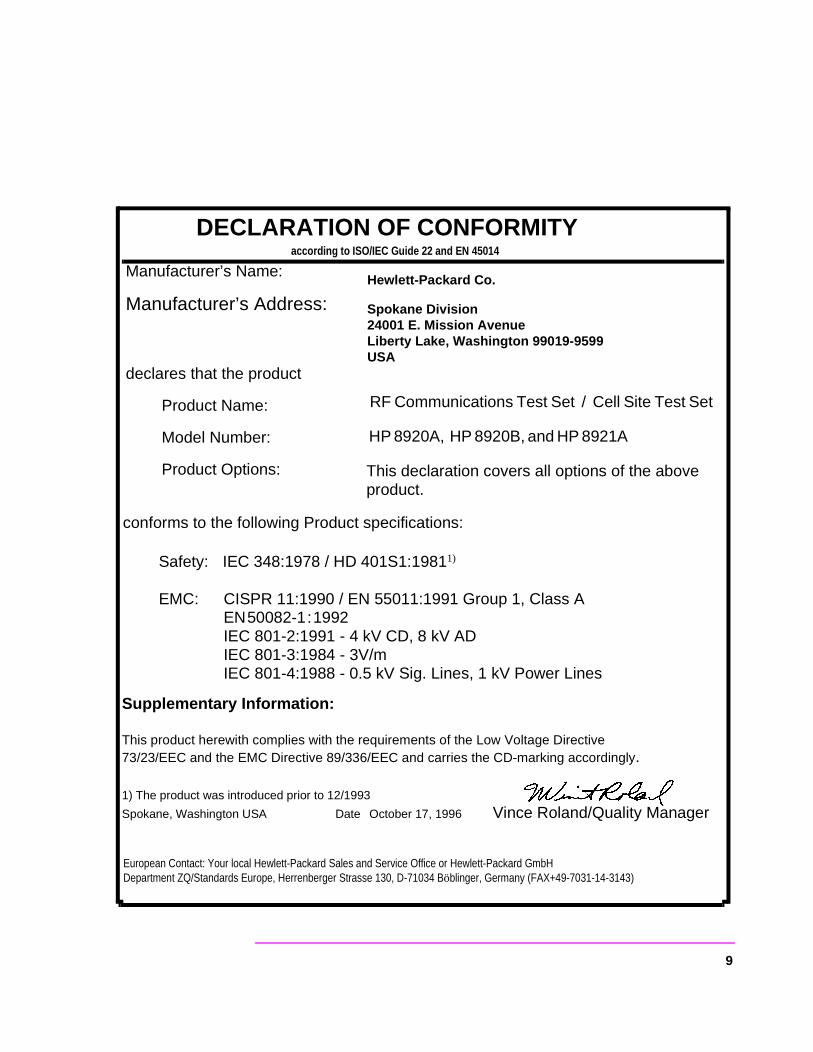
European Contact: Your local Hewlett-Packard Sales and Service Office or Hewlett-Packard GmbHDepartment ZQ/Standards Europe, Herrenberger Strasse 130, D-71034 Böblinger, Germany (FAX+49-7031-14-3143)
DECLARATION OF CONFORMITY according to ISO/IEC Guide 22 and EN 45014
Manufacturer’s Name:
Manufacturer’s Address:
declares that the product
Product Name:
Model Number:
Product Options:
Hewlett-Packard Co.
Spokane Division24001 E. Mission AvenueLiberty Lake, Washington 99019-9599USA
RF Communications Test Set / Cell Site Test Set
HP 8920A, HP 8920B, and HP 8921A
This declaration covers all options of the above product.
conforms to the following Product specifications:
Safety: IEC 348:1978 / HD 401S1:19811)
EMC: CISPR 11:1990 / EN 55011:1991 Group 1, Class A EN 50082-1 : 1992 IEC 801-2:1991 - 4 kV CD, 8 kV ADIEC 801-3:1984 - 3V/mIEC 801-4:1988 - 0.5 kV Sig. Lines, 1 kV Power Lines
Supplementary Information:
This product herewith complies with the requirements of the Low Voltage Directive 73/23/EEC and the EMC Directive 89/336/EEC and carries the CD-marking accordingly.
1) The product was introduced prior to 12/1993
Spokane, Washington USA Date October 17, 1996 Vince Roland/Quality Manager
9
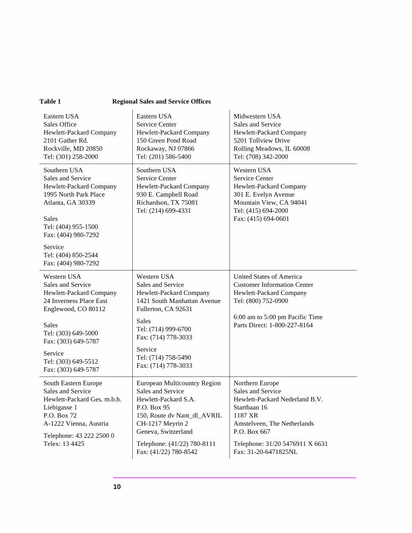
Table 1 Regional Sales and Service Offices
Eastern USASales OfficeHewlett-Packard Company2101 Gather Rd.Rockville, MD 20850Tel: (301) 258-2000
Eastern USAService CenterHewlett-Packard Company150 Green Pond RoadRockaway, NJ 07866Tel: (201) 586-5400
Midwestern USASales and ServiceHewlett-Packard Company5201 Tollview DriveRolling Meadows, IL 60008Tel: (708) 342-2000
Southern USASales and ServiceHewlett-Packard Company1995 North Park PlaceAtlanta, GA 30339
SalesTel: (404) 955-1500Fax: (404) 980-7292
Service Tel: (404) 850-2544Fax: (404) 980-7292
Southern USAService CenterHewlett-Packard Company930 E. Campbell RoadRichardson, TX 75081Tel: (214) 699-4331
Western USAService CenterHewlett-Packard Company301 E. Evelyn AvenueMountain View, CA 94041Tel: (415) 694-2000Fax: (415) 694-0601
Western USASales and ServiceHewlett-Packard Company24 Inverness Place EastEnglewood, CO 80112
SalesTel: (303) 649-5000Fax: (303) 649-5787
ServiceTel: (303) 649-5512Fax: (303) 649-5787
Western USASales and ServiceHewlett-Packard Company1421 South Manhattan AvenueFullerton, CA 92631
SalesTel: (714) 999-6700Fax: (714) 778-3033
ServiceTel: (714) 758-5490Fax: (714) 778-3033
United States of AmericaCustomer Information CenterHewlett-Packard CompanyTel: (800) 752-0900
6:00 am to 5:00 pm Pacific TimeParts Direct: 1-800-227-8164
South Eastern EuropeSales and ServiceHewlett-Packard Ges. m.b.h.Liebigasse 1P.O. Box 72A-1222 Vienna, Austria
Telephone: 43 222 2500 0Telex: 13 4425
European Multicountry RegionSales and ServiceHewlett-Packard S.A.P.O. Box 95150, Route dv Nant_dl_AVRILCH-1217 Meyrin 2Geneva, Switzerland
Telephone: (41/22) 780-8111Fax: (41/22) 780-8542
Northern EuropeSales and ServiceHewlett-Packard Nederland B.V.Startbaan 161187 XRAmstelveen, The NetherlandsP.O. Box 667
Telephone: 31/20 5476911 X 6631Fax: 31-20-6471825NL
10

AsiaSales and ServiceHewlett-Packard Asia Ltd.22-30/F Peregrine TowerLippo Center89 Queensway, CentralHong KongG.P.O. Box 863 Hong Kong
Telephone: 852-848-7777Fax: 852-868-4997
JapanSales and ServiceHewlett-Packard Japan, Ltd.3-29-21, Takaido-HigashiSuginami-Ku, Tokyo 168
Telephone: 81 3 3331-6111Fax: 81 3 3331-6631
International Sales Branch HeadquartersSales and ServiceHewlett-Packard S.A.39 Rue VeyrotP.O. Box 3651217 Meyrin 1Geneva, Switzerland
Telephone: 41-22-780-4111Fax: 41-22-780-4770
Australia, New ZealandSales and ServiceHewlett-Packard Ltd.P.O. Box 22131-41 Joseph StreetBlackburn, Victoria 3130
Telephone: (61/3) 895-2895Fax: (61/3) 898-9257
CanadaSales and ServiceHewlett-Packard (Canada) Ltd.5150 Spectrum WayMississauga, Ontario L4W 5G1Canada
Telephone: (416) 206-4725Fax: (416) 206-4739
CanadaService CenterHewlett-Packard Company17500 Transcanada HighwayS. Serv RoadKirkland, Quebec H9J 2X8Canada
Telephone: (416) 206-3295
CanadaService CenterHewlett-Packard Ltd.11120 178 StreetEdmonton, Alberta T5S 1P2Canada
Telephone: (403) 486-6666Fax: (403) 489-8764
Latin AmericaHewlett-Packard CompanyLAHQ Mexico CityCol. Lomas de Virreyes11000 Mexico D.F.Mexico
Telephone: (52/5) 326-4000Fax: (52/5) 202 7718
United KingdomSales and ServiceHewlett-Packard Ltd.Cain RoadAmen CornerBracknell, BerkshireRG12 1HNUnited Kingdom
Telephone: 44 344 360000Fax: 44 344 363344
Table 1 Regional Sales and Service Offices
11
S,
e
tem
nt
et’s
or then
gn, +.
e
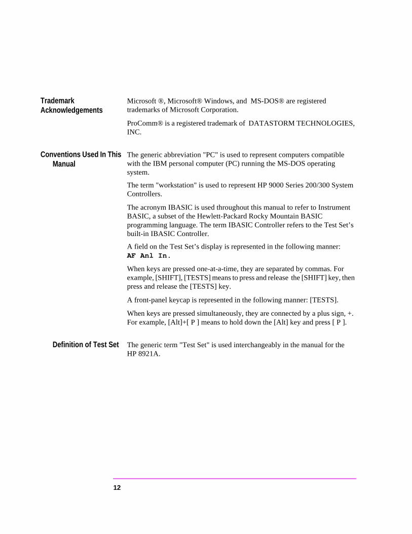
Trademark Acknowledgements
Microsoft ®, Microsoft® Windows, and MS-DOS® are registered trademarks of Microsoft Corporation.
ProComm® is a registered trademark of DATASTORM TECHNOLOGIEINC.
Conventions Used In This Manual
The generic abbreviation "PC" is used to represent computers compatiblwith the IBM personal computer (PC) running the MS-DOS operating system.
The term "workstation" is used to represent HP 9000 Series 200/300 SysControllers.
The acronym IBASIC is used throughout this manual to refer to InstrumeBASIC, a subset of the Hewlett-Packard Rocky Mountain BASIC programming language. The term IBASIC Controller refers to the Test Sbuilt-in IBASIC Controller.
A field on the Test Set’s display is represented in the following manner: AF Anl In.
When keys are pressed one-at-a-time, they are separated by commas. Fexample, [SHIFT], [TESTS] means to press and release the [SHIFT] key, press and release the [TESTS] key.
A front-panel keycap is represented in the following manner: [TESTS].
When keys are pressed simultaneously, they are connected by a plus siFor example, [Alt]+[ P ] means to hold down the [Alt] key and press [ P ].
Definition of Test Set The generic term "Test Set" is used interchangeably in the manual for thHP 8921A.
12
ew ms,
flow ges to ng.
Set s.
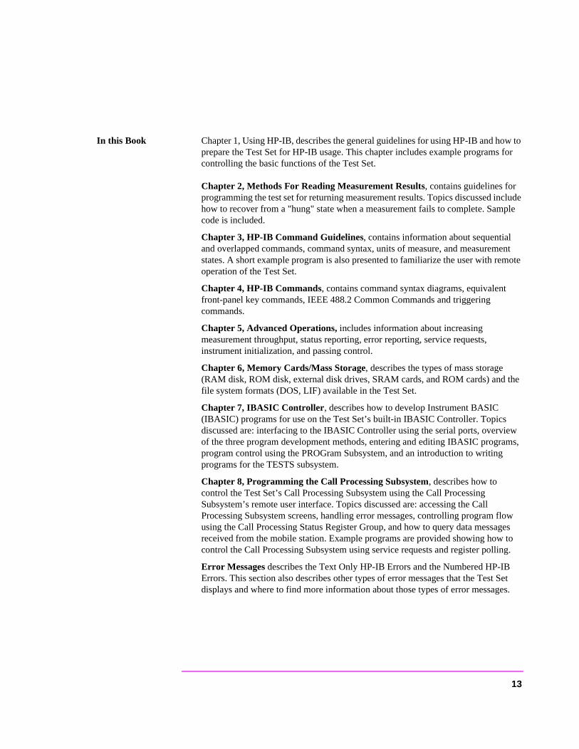
In this Book Chapter 1, Using HP-IB, describes the general guidelines for using HP-IB and how to prepare the Test Set for HP-IB usage. This chapter includes example programs for controlling the basic functions of the Test Set.
Chapter 2, Methods For Reading Measurement Results, contains guidelines for programming the test set for returning measurement results. Topics discussed include how to recover from a "hung" state when a measurement fails to complete. Sample code is included.
Chapter 3, HP-IB Command Guidelines, contains information about sequential and overlapped commands, command syntax, units of measure, and measurement states. A short example program is also presented to familiarize the user with remote operation of the Test Set.
Chapter 4, HP-IB Commands, contains command syntax diagrams, equivalent front-panel key commands, IEEE 488.2 Common Commands and triggering commands.
Chapter 5, Advanced Operations, includes information about increasing measurement throughput, status reporting, error reporting, service requests, instrument initialization, and passing control.
Chapter 6, Memory Cards/Mass Storage, describes the types of mass storage (RAM disk, ROM disk, external disk drives, SRAM cards, and ROM cards) and the file system formats (DOS, LIF) available in the Test Set.
Chapter 7, IBASIC Controller, describes how to develop Instrument BASIC (IBASIC) programs for use on the Test Set’s built-in IBASIC Controller. Topics discussed are: interfacing to the IBASIC Controller using the serial ports, overviof the three program development methods, entering and editing IBASIC prograprogram control using the PROGram Subsystem, and an introduction to writing programs for the TESTS subsystem.
Chapter 8, Programming the Call Processing Subsystem, describes how to control the Test Set’s Call Processing Subsystem using the Call Processing Subsystem’s remote user interface. Topics discussed are: accessing the Call Processing Subsystem screens, handling error messages, controlling program using the Call Processing Status Register Group, and how to query data messareceived from the mobile station. Example programs are provided showing howcontrol the Call Processing Subsystem using service requests and register polli
Error Messages describes the Text Only HP-IB Errors and the Numbered HP-IBErrors. This section also describes other types of error messages that the Test displays and where to find more information about those types of error message
13

14
Contents
1 Using HP-IB
Overview of the Test Set 28
Getting Started 36
Remote Operation 49
Addressing 51
IEEE 488.1 Remote Interface Message Capabilities 52
Remote/Local Modes 55
15
Contents
2 Methods For Reading Measurement Results
Background 60
HP BASIC ‘ON TIMEOUT’ Example Program 62
HP BASIC ‘MAV’ Example Program 66
16
Contents
3 HP-IB Command Guidelines
Sequential and Overlapped Commands 72
Guidelines for Operation 73
17
Contents
4 HP-IB Commands
HP-IB Syntax Diagrams 96
Adjacent Channel Power (ACP) 99
AF Analyzer 101
AF Generator 1 104
AF Generator 2 Pre-Modulation Filters 105
AF Generator 2/Encoder 106
Configure, I/O Configure 121
Call Processing 126
Decoder 145
Display 149
Measure 151
Oscilloscope 158
Program 163
Save/Recall Registers 164
RF Analyzer 165
RF Generator 167
Radio Interface 168
Spectrum Analyzer 169
HP-IB Only Commands 171
18
Contents
Status 172
System 173
Tests 174
Trigger 177
Integer Number Setting Syntax 178
Real Number Setting Syntax 179
Multiple Real Number Setting Syntax 180
Number Measurement Syntax 181
Multiple Number Measurement Syntax 183
Equivalent Front-Panel Key Commands 184
IEEE 488.2 Common Commands 212
Common Command Descriptions 213
Triggering Measurements 228
19
Contents
5 Advanced Operations
Increasing Measurement Throughput 238
Status Reporting 244
HP-IB Service Requests 295
Instrument Initialization 305
Passing Control 318
20
Contents
6 Memory Cards/Mass Storage
Default File System 330
Mass Storage Device Overview 331
Default Mass Storage Locations 338
Mass Storage Access 340
DOS and LIF File System Considerations 341
Using the ROM Disk 348
Using Memory Cards 349
Backing Up Procedure and Library Files 354
Copying Files Using IBASIC Commands 355
Using RAM Disk 357
Using External Disk Drives 359
21
Contents
7 IBASIC Controller
Introduction 362
The IBASIC Controller Screen 363
Important Notes for Program Development 365
Program Development 366
Interfacing to the IBASIC Controller using Serial Ports 368
Choosing Your Development Method 382
Method #1. Program Development on an External BASIC Language Computer 384
Method #2. Developing Programs on the Test Set Using the IBASIC EDIT Mode 392
Method #3. Developing Programs Using Word Processor on a PC (Least Preferred) 397
Uploading Programs from the Test Set to a PC 404
Serial I/O from IBASIC Programs 405
PROGram Subsystem 408
The TESTS Subsystem 436
22
Contents
448
8 Programming The Call Processing Subsystem
Description of the Call Processing Subsystem’s Remote User Interface 444
Using the Call Processing Subsystem’s Remote User Interface
Programming The CALL CONTROL Screen 458
Programming The CALL DATA Screen 486
CALL DATA Screen Message Field Descriptions 490
Programming The CALL BIT Screen 501
CALL BIT Screen Message Field Descriptions 512
Programming The ANALOG MEAS Screen 532
Programming The CALL CONFIGURE Screen 540
Example Programs 543
23

Contents
9 Error Messages
24

Contents
Index 593
25

Contents
26
1
Using HP-IB
27

Chapter 1, Using HP-IBOverview of the Test Set
an t-in
asic
it.
n ilt-in
l et’s IC
-IB
Overview of the Test Set
The Test Set combines up to 22 separate test instruments and an Instrument BASIC (IBASIC) Controller into one package. All of the Test Set’s functions cbe automatically controlled through application programs running on the builIBASIC Controller or on an external controller connected through HP-IB.
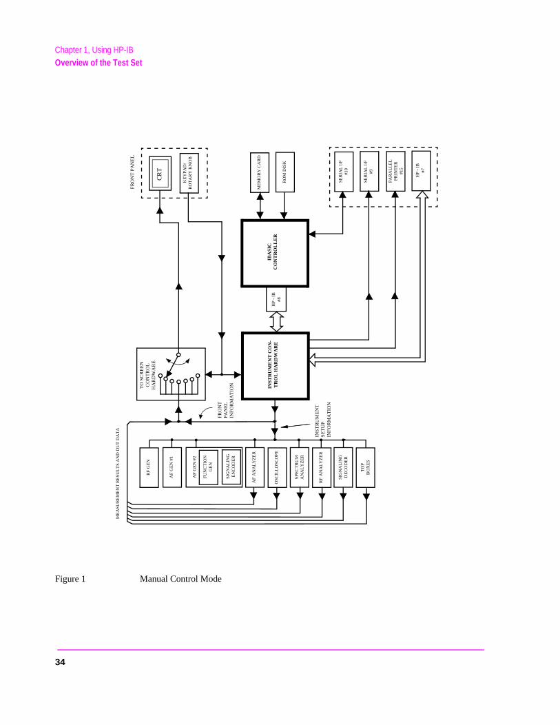
Developing programs for the Test Set is simplified if the programmer has a bunderstanding of how the Test Set operates. An overview of the Test Set’s operation is best presented in terms of how information flows through the unThe simplified block diagrams shown in figure 1 on page 34 and figure 2 on page 35 depict how instrument control information and measurement result informatioare routed among the Test Set’s instruments, instrument control hardware, buIBASIC controller, and other components.
The Test Set has two operating modes: Manual Control mode and AutomaticControl mode. In Manual Control mode the Test Set’s operation is controlledthrough the front panel keypad/rotary knob. There are two Automatic Contromodes: Internal and External. In Internal Automatic Control mode the Test Soperation is controlled by an application program running on the built-in IBASController. In External Automatic Control mode the Test Set’s operation is controlled by an external controller connected to the Test Set through the HPinterface.
28

Chapter 1, Using HP-IBOverview of the Test Set
r, AF
er). n
to s the the
ront ent
of a mple, o ok at m RF
ent or
e and
an r data
et. l e
Manual Control Mode
The Test Set’s primary instruments are shown on the left side of figure 1 . There are two classes of instruments in the Test Set: signal analyzers (RF AnalyzeAnalyzer, Oscilloscope, Spectrum Analyzer, Signaling Decoder) and signal sources (RF Generator, AF Generator #1, AF Generator #2/Signaling EncodThe Test Set’s measurement capability can be extended by adding applicatiospecific “top boxes” such as the HP 83201A Dual Mode Cellular Adapter.
Since so many instruments are integrated into the Test Set, it is not feasible have an actual “front panel” for each instrument. Therefore, each instrument’front panel is maintained in firmware and is displayed on the CRT whenever instrument is selected. Only one instrument front panel can be displayed on CRT at any given time (up to four measurement results can be displayed simultaneously if desired). Just as with stand alone instruments, instrument fpanels in the Test Set can contain instrument setting information, measuremresult(s), or data input from the DUT.
Using the Test Set in Manual Control mode is very analogous to using a set bench or rack-mounted test equipment. To obtain a measurement result withbench or racked system, the desired measurement must be “active.” For exaif an RF power meter is in the bench or racked system and the user wishes tmeasure the power of an RF carrier they must turn the power meter on, and lothe front panel to see the measurement result. Other instruments in the systemay be turned off but this would not prevent the operator from measuring thepower.
Conceptually, the same is true for the Test Set. In order to make a measureminput data from a DUT, the desired measurement field or data field must be “active.” This is done by using the front panel keypad/rotary knob to select thinstrument whose front panel contains the desired measurement or data fieldmaking sure that the desired measurement or data field is turned ON.
Figure 1 shows that instrument selection is handled by the To Screen controlhardware which routes the selected instrument’s front panel to the CRT for display. Once an instrument’s front panel is displayed on the CRT, the user cmanipulate the instrument settings, such as turning a specific measurement ofield on or off, using the keypad/rotary knob. Figure 1 also shows that instrumentsetup is handled by the Instrument Control hardware which routes setup information from the front panel to the individual instruments.
An HP-IB/RS-232/Parallel Printer interface capability is available in the Test SIn Manual Control mode this provides the capability of connecting an externaHP-IB, serial, or parallel printer to the Test Set so that display screens can bprinted.
29
Chapter 1, Using HP-IBOverview of the Test Set
an
f ries
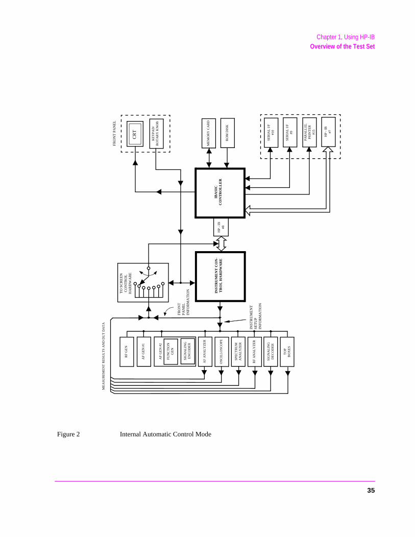
Internal Automatic Control Mode
In Internal Automatic Control mode the Test Set’s operation is controlled by application program running on the built-in Instrument BASIC (IBASIC) Controller. The built-in controller runs programs written in IBASIC, a subset othe Hewlett-Packard BASIC programming language used on the HP 9000 Se200/300 System Controllers. IBASIC is the only programming language supported on the built-in IBASIC Controller.
Similarities Between the Test Set’s IBASIC Controller and Other Single-Tasking Controllers
The architecture of the IBASIC Controller is similar to that of other single-tasking instrumentation controllers. Only one program can be run on the IBASIC Controller at any given time. The program is loaded into RAM memory from some type of mass storage device. Five types of mass storage devices are available to the Test Set: SRAM memory cards, ROM memory cards, external disk drives connected to the HP-IB interface, internal RAM disc, and internal ROM disc. Three types of interfaces are available for connecting to external instruments and equipment: HP-IB, RS-232, and 16-bit parallel (available as Opt 020 Radio Interface Card).
Figure 2 shows how information is routed inside the Test Set when it is in Internal Automatic Control mode. In Manual Control mode certain Test Set resources are dedicated to manual operation. These resources are switched to the IBASIC Controller when an IBASIC program is running. These include the serial interface at select code 9, the HP-IB interface at select code 7, the parallel printer interface at select code 15, and the CRT. In Manual Control mode, front panel information (instrument settings, measurement results, data input from the DUT) is routed to the CRT through the To Screen control hardware. In Internal Automatic Control mode the measurement results and data input from the DUT are routed to the IBASIC Controller through a dedicated HP-IB interface. Also, in Internal Automatic Control mode, the CRT is dedicated to the IBASIC Controller for program and graphics display. This means instrument front panels cannot be displayed on the CRT when an IBASIC program is running.
30

Chapter 1, Using HP-IBOverview of the Test Set
ing SIC for
is
8 in al this
ard
does ich
t.
Differences Between the Test Set’s IBASIC Controller and Other Single-Tasking Controllers
The IBASIC Controller is unlike other single tasking instrumentation controllers in several ways. First, it does not have a keyboard. This imposes some limitations on creating and editing IBASIC programs directly on the Test Set. In Internal Automatic Control mode a “virtual” keyboard is available in firmware which allows the operator to enter alphanumeric data into a dedicated input field usthe rotary knob. This is not the recommended programming mode for the IBAController. This feature is provided to allow user access to IBASIC programsshort edits or troubleshooting. Several programming modes for developing IBASIC programs to run on the internal IBASIC Controller are discussed in thmanual.
Secondly, the IBASIC Controller has a dedicated HP-IB interface, select codefigure 2 , for communicating with the internal instruments of the Test Set. ThisHP-IB interface is only available to the IBASIC Controller. There is no externconnector for this HP-IB interface. No external instruments may be added to HP-IB interface. The HP-IB interface, select code 7 in figure 2 , is used to interface the Test Set to external instruments or to an external controller. Thededicated HP-IB interface at select code 8 conforms to the IEEE 488.2 Standin all respects but one. The difference being that each instrument on the busnot have a unique address. The Instrument Control Hardware determines whinstrument is being addressed through the command syntax. Refer to chapter 4, "HP-IB Commands" for a listing of the HP-IB command syntax for the Test Se
31
Chapter 1, Using HP-IBOverview of the Test Set
an en in ame
ual d to e
le as ons ss
to be
External Automatic Control Mode
In External Automatic Control mode the Test Set’s operation is controlled by external controller connected to the Test Set through the HP-IB interface. WhExternal Automatic Control mode the Test Set’s internal configuration is the sas in Manual Control Mode with two exceptions:
1. Configuration and setup commands are received through the external HP-IB interface, select code 7, rather than from the front-panel keypad/rotary knob.
2. The MEASure command is used to obtain measurement results and DUT data through the external HP-IB interface.
Figure 1 on page 34 shows how information is routed inside the Test Set in ManControl mode. Figure 1 also shows that certain Test Set resources are dedicatethe IBASIC Controller (Memory Card, ROM disk, Serial Interface #10) and arnot directly accessible to the user in Manual Control Mode. In addition, figure 1 shows that Serial Interface #9 and Parallel Printer Interface #15 are accessibwrite-only interfaces for printing in Manual Control mode. These same conditiare true when in External Automatic Control mode. If the user wished to accethese resources from an external controller, an IBASIC program would have run on the Test Set from the external controller.
32

Chapter 1, Using HP-IBOverview of the Test Set
this the using
the that first
Writing programs for the Test Set
One of the design goals for automatic control of the Test Set was that it operate the same way programmatically as it does manually. This is a key point to remember when developing programs for the Test Set. The benefit of this approach is that to automate a particular task, one need only figure out how to do the task manually and then duplicate the same process in software. This has several implications when designing and writing programs for the Test Set:
1. In Manual Control mode a measurement must be “active” in order to obtain a measurement result or input data from the DUT. From a programming perspectivemeans that before attempting to read a measurement result or to input data fromDUT, the desired screen for the measurement result or data field must be selectedthe DISPlay command and the field must be in the ON state.
2. In Manual Control mode instrument configuration information is not routed throughTo Screen control hardware block. From a programming perspective this means configuration information can be sent to any desired instrument without having to select the instrument’s front panel with the DISPlay command.
Keeping these points in mind during program development will minimize program development time and reduce problems encountered when running the program.
33
Chapter 1, Using HP-IBOverview of the Test Set
Figure 1 Manual Control Mode
CR
T
KE
YP
AD
/R
OT
AR
Y K
NO
B
TO
SC
RE
EN
CO
NT
RO
LH
AR
DW
AR
E
INST
RU
ME
NT
CO
N-
TR
OL
HA
RD
WA
RE
ME
MO
RY
CA
RD
RO
M D
ISK
IBA
SIC
CO
NT
RO
LL
ER
HP
- I
B#8
SE
RIA
L I
/F#1
0
SE
RIA
L I
/F#9
PA
RA
LL
EL
PR
INT
ER
#15
HP
- I
B#7
RF
GE
N
AF
GE
N #
1
AF
GE
N #
2
FU
NC
TIO
NG
EN
SIG
NA
LIN
GE
NC
OD
ER
AF
AN
AL
YZ
ER
OS
CIL
LO
SC
OP
E
SP
EC
TR
UM
AN
AL
YZ
ER
RF
AN
AL
YZ
ER
SIG
NA
LIN
GD
EC
OD
ER
TO
PB
OX
ES
FR
ON
T P
AN
EL
INS
TR
UM
EN
TS
ET
UP
INF
OR
MA
TIO
N
FRO
NT
PAN
EL
INF
OR
MA
TIO
N
ME
AS
UR
EM
EN
T R
ES
UL
TS
AN
D D
UT
DA
TA
34
Chapter 1, Using HP-IBOverview of the Test Set
Figure 2 Internal Automatic Control Mode
CR
T
KE
YP
AD
/R
OT
AR
Y K
NO
B
TO
SC
RE
EN
CO
NT
RO
LH
AR
DW
AR
E
INS
TR
UM
EN
T C
ON
-T
RO
L H
AR
DW
AR
E
ME
MO
RY
CA
RD
RO
M D
ISK
IBA
SIC
CO
NT
RO
LL
ER
HP
- I
B#8
SE
RIA
L I
/F#1
0
SE
RIA
L I
/F#9
PA
RA
LL
EL
PR
INT
ER
#15
HP
- I
B#7
RF
GE
N
AF
GE
N #
1
AF
GE
N #
2
FU
NC
TIO
NG
EN
SIG
NA
LIN
GE
NC
OD
ER
AF
AN
AL
YZ
ER
OS
CIL
LO
SC
OP
E
SP
EC
TR
UM
AN
AL
YZ
ER
RF
AN
AL
YZ
ER
SIG
NA
LIN
GD
EC
OD
ER
TO
PB
OX
ES
FR
ON
T P
AN
EL
INST
RU
ME
NT
SE
TU
PIN
FOR
MA
TIO
N
FR
ON
TP
AN
EL
INFO
RM
AT
ION
ME
AS
UR
EM
EN
T R
ES
UL
TS
AN
D D
UT
DA
TA
35

Chapter 1, Using HP-IBGetting Started
tion
l
’s
ty.)
ts
Test
and
Getting Started
What is HP-IB?
The Hewlett-Packard Interface Bus (HP-IB) is Hewlett-Packard’s implementaof the IEEE 488.1-1987 Standard Digital Interface for Programmable Instrumentation. Incorporation of the HP-IB into the Test Set provides severavaluable capabilities:
• Programs running in the Test Set’s IBASIC Controller can control all the Test Setfunctions using its internal HP-IB. This capability provides a single-instrument automated test system. (The HP 11807 Radio Test Software utilizes this capabili
• Programs running in the Test Set’s IBASIC Controller can control other instrumenconnected to the external HP-IB.
• An external controller, connected to the external HP-IB, can remotely control the Set.
• An HP-IB printer, connected to the external HP-IB, can be used to print test resultsfull screen images.
36
Chapter 1, Using HP-IBGetting Started
HP-IB Information Provided in This Manual
What Is Explained
How to configure the Test Set for HP-IB operation
• How to make an instrument setting over HP-IB
• How to read-back instrument settings over HP-IB
• How to make measurements over HP-IB
• How to connect external PCs, terminals or controllers to the Test Set
• HP-IB command syntax for the Test Set
• IBASIC program development
• IBASIC program transfer over HP-IB
• Various advanced functions such as, increasing measurement throughput, statusreporting, error reporting, pass control, and so forth
What Is Not Explained
• HP-IB (IEEE 488.1, 488.2) theory of operation1
• HP-IB electrical specifications1
• HP-IB connector pin functions1
• IBASIC programming (other than general guidelines related to HP-IB)2
1. Refer to the Tutorial Description of the Hewlett-Packard Interface Bus(HP P/N 5952-0156) for detailed information on HP-IB theory and operation.2. For the HP 8921A refer to the HP Instrument BASIC Users Handbook (HP P/N E2083-90601) for more information on the IBASIC Version 1.0 language.
37
Chapter 1, Using HP-IBGetting Started
of re
s
s sentfields
s as
tion
ce
General HP-IB Programming Guidelines
The following guidelines should be considered when developing programs which control the Test Set through HP-IB:
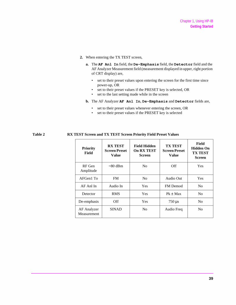
• Guideline #1. Avoid using the TX TEST and RX TEST screens.
The RX TEST and TX TEST screens are specifically designed for manual testingland mobile FM radios and, when displayed, automatically configure six “priority”fields in the Test Set for this purpose. The priority fields and their preset values alisted in table 2 on page 39. When the TX TEST screen or the RX TEST screen is displayed, certain priority fields are hidden and are not settable. The priority fieldwhich are hidden are listed in table 2 on page 39.
NOTE: When the TX TEST screen or the RX TEST screen is displayed, any HP-IB commandto the Test Set to change the value of a hidden priority field are ignored. Hidden priority on the TX TEST or RX TEST screens are not settable manually or programmatically.
Displaying either of these screens automatically re-configures the 6 “priority” fieldfollows:
1. When entering the RX TEST screen,
a. the RF Generator’s Amplitude field, the AFGen1 To field and the AF Analyzer’s measurement field (measurement displayed in upper, right porof CRT display) are
• set to their preset values upon entering the screen for the first time sinpower-up, OR
• set to their preset values if the PRESET key is selected, OR • set to the last setting made while in the screen
b. the RF Generator Amplitude field and the AFGen1 To field are
• set to their preset values whenever entering the screen, OR • set to their preset values if the PRESET key is selected
38
Chapter 1, Using HP-IBGetting Started
ce
2. When entering the TX TEST screen,
a. The AF Anl In field, the De-Emphasis field, the Detector field and the AF Analyzer Measurement field (measurement displayed in upper, right portion of CRT display) are,
• set to their preset values upon entering the screen for the first time sinpower-up, OR
• set to their preset values if the PRESET key is selected, OR • set to the last setting made while in the screen
b. The AF Analyzer AF Anl In, De-Emphasis and Detector fields are,
• set to their preset values whenever entering the screen, OR • set to their preset values if the PRESET key is selected
Table 2 RX TEST Screen and TX TEST Screen Priority Field Preset Values
Priority Field
RX TEST Screen Preset
Value
Field Hidden On RX TEST
Screen
TX TEST Screen Preset
Value
Field Hidden On TX TEST
Screen
RF Gen Amplitude
−80 dBm No Off Yes
AFGen1 To FM No Audio Out Yes
AF Anl In Audio In Yes FM Demod No
Detector RMS Yes Pk ± Max No
De-emphasis Off Yes 750 µs No
AF Analyzer Measurement
SINAD No Audio Freq No
39
Chapter 1, Using HP-IBGetting Started
his
nitial s in a
t. n each ecomes
uire
e sure preset ires ed by
foron theausestically.mmand
te for , the
eld
ST trigger
• Guideline #2. When developing programs to make measurements always follow trecommended sequence:
1. Bring the Test Set to its preset state using the front-panel PRESET key. This istep allows you to start developing the measurement sequence with most fieldknown state.
2. Make the measurement manually using the front-panel controls of the Test SeRecord, in sequential order, the screens selected and the settings made withiscreen. The record of the screens selected and settings made in each screen bthe measurement procedure.
3. Record the measurement result(s).
In addition to the DISPlay command, the signaling ENCoder and DECoder reqfurther commands to display the correct fields for each signaling mode. For example, DISP ENC;:ENC:MODE 'DTMF'.
4. Develop the program using the measurement procedure generated in step 2. Bto start the programmatic measurement sequence by bringing the Test Set to itsstate using the *RST Common Command. As the measurement procedure requchanging screens, use the DISPlay command to select the desired screen followthe correct commands to set the desired field(s).
NOTE: When IBASIC programs are running the CRT is dedicated to the IBASIC Controllerprogram and graphics display. This means instrument front panels are not displayed CRT when an IBASIC program is running. However, the DISPlay <screen> command call setting and measurement fields in the <screen> to be accessible programmaAttempting to read from a screen that has not been made accessible by the DISPlay cowill cause HP-IB Error:-420 Query UNTERMINATED, or HP-IB Error: -113 Undefined header
5. Make sure the desired measurement is in the ON state. This is the preset stamost measurements. However, if a previous program has set the state to OFFmeasurement will not be available. Attempting to read from a measurement fithat is not in the ON state will cause HP-IB Error:-420 Query UNTERMINATED.
6. If the trigger mode has been changed, trigger a reading.
NOTE: Triggering is set to FULL SETTling and REPetitive RETRiggering after receipt of the *RCommon Command. These settings cause the Test Set to trigger itself and a separatecommand is not necessary.
40
Chapter 1, Using HP-IBGetting Started
DC SELect
the
reset F
ays RF RF
ed tup lso g
7. Send the MEASure query command to initiate a reading. This will place the measured value into the Test Set’s Output Queue.
NOTE: When making AF Analyzer SINAD, Distortion, Signal to Noise Ratio, AF Frequency, Level, or Current measurements, the measurement type must first be selected using thecommand. For example, MEAS:AFR:SEL'SINAD' followed by MEAS:AFR:SINAD?
8. Use the ENTER statement to transfer the measured value to a variable withincontext of the program.
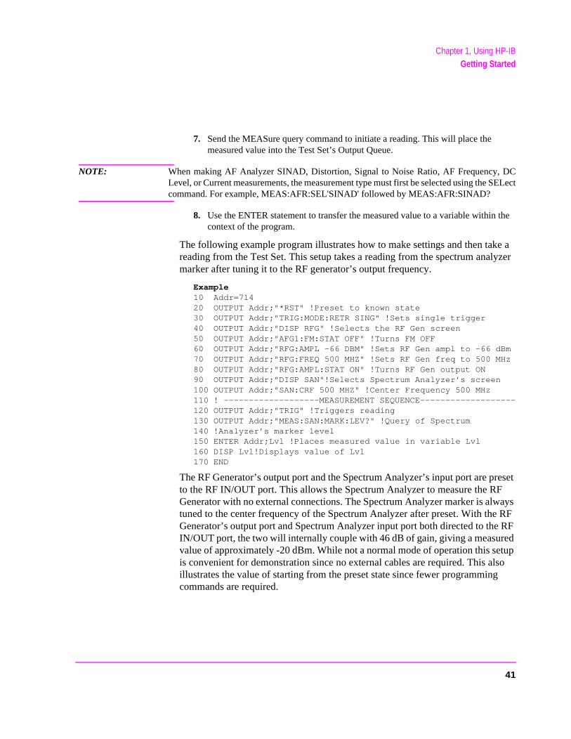
The following example program illustrates how to make settings and then take a reading from the Test Set. This setup takes a reading from the spectrum analyzer marker after tuning it to the RF generator’s output frequency.
Example10 Addr=71420 OUTPUT Addr;"*RST" !Preset to known state30 OUTPUT Addr;"TRIG:MODE:RETR SING" !Sets single trigger40 OUTPUT Addr;"DISP RFG" !Selects the RF Gen screen50 OUTPUT Addr;"AFG1:FM:STAT OFF" !Turns FM OFF60 OUTPUT Addr;"RFG:AMPL -66 DBM" !Sets RF Gen ampl to -66 dBm70 OUTPUT Addr;"RFG:FREQ 500 MHZ" !Sets RF Gen freq to 500 MHz80 OUTPUT Addr;"RFG:AMPL:STAT ON" !Turns RF Gen output ON90 OUTPUT Addr;"DISP SAN"!Selects Spectrum Analyzer’s screen100 OUTPUT Addr;"SAN:CRF 500 MHZ" !Center Frequency 500 MHz110 ! -------------------MEASUREMENT SEQUENCE-------------------120 OUTPUT Addr;"TRIG" !Triggers reading130 OUTPUT Addr;"MEAS:SAN:MARK:LEV?" !Query of Spectrum 140 !Analyzer’s marker level150 ENTER Addr;Lvl !Places measured value in variable Lvl160 DISP Lvl!Displays value of Lvl170 END
The RF Generator’s output port and the Spectrum Analyzer’s input port are pto the RF IN/OUT port. This allows the Spectrum Analyzer to measure the RGenerator with no external connections. The Spectrum Analyzer marker is alwtuned to the center frequency of the Spectrum Analyzer after preset. With theGenerator’s output port and Spectrum Analyzer input port both directed to theIN/OUT port, the two will internally couple with 46 dB of gain, giving a measurvalue of approximately -20 dBm. While not a normal mode of operation this seis convenient for demonstration since no external cables are required. This aillustrates the value of starting from the preset state since fewer programmincommands are required.
41
Chapter 1, Using HP-IBGetting Started
ost ns
efore
hes gth eld r to
er t is
ously
d a
nt RX n by
• Guideline #3. Avoid program hangs.
If the program stops or “hangs up” when trying to ENTER a measured value, it is mlikely that the desired measurement field is not available. There are several reasothat can happen:
1. The screen where the measurement field is located has not been DISPlayed bquerying the measurement field.
2. The measurement is not turned ON.
3. The squelch control is set too high. If a measurement is turned ON but is not available due to the Squelch setting, the measurement field contains four das(- - - -). This is a valid state. The Test Set is waiting for a signal of sufficient strento unsquelch the receiver before making a measurement. If a measurement fiwhich is squelched is queried the Test Set will wait indefinitely for the receiveunsquelch and return a measured value.
4. The RF Analyzer’s Input Port is set to ANT (antenna) while trying to read TX power. TX power is not measurable with the Input Port set to ANT. The TX powmeasurement field will display four dashes (- - - -) indicating the measuremenunavailable.
5. The input signal to the Test Set is very unstable causing the Test Set to continuautorange. This condition will be apparent if an attempt is made to make the measurement manually.
6. Trigger mode has been set to single trigger (TRIG:MODE:RETRig SINGle) annew measurement cycle has not been triggered before attempting to read themeasured value.
7. The program is attempting to make an FM deviation or AM depth measuremewhile in the RX TEST screen. FM or AM measurements are not available in theTEST screen. FM or AM measurements are made from the AF Analyzer screesetting the AF Anl In field to FM or AM Demod.
42
Chapter 1, Using HP-IBGetting Started
and.
lue t to
one el in ngle
• Guideline #4. Use single quotes and spaces properly.
The syntax diagrams in chapter 4, "HP-IB Commands," show where single quotes are needed and where spaces are needed.
Example
OUTPUT 714;"DISP<space>AFAN" OUTPUT 714;"AFAN:DEMP<space>’Off’"
Improper use of single quotes and spaces will cause,HP-IB Error:-103 Invalid Separator
• Guideline #5. Ensure that settable fields are active by using the STATe ON comm
When making settings to fields that can be turned OFF with the STATe ON/OFF command (refer to the Chapter 4, "HP-IB Commands"), make sure the STATe is ON if the program uses that field. Note that if the STATe is OFF, just setting a numeric value in the field will not change the STATe to ON. This is different thanfront-panel operation whereby the process of selecting the field and entering a vaautomatically sets the STATe to ON. Programmatically, fields must be explicitly sethe ON state if they are in the OFF state.
For example, the following command line would set a new AMPS ENCoder SAT tdeviation and then turn on the SAT tone (note the use of the ; to back up one levthe command hierarchy so that more than one command can be executed in a siline):
Example
OUTPUT 714;"ENC:AMPS:SAT:FM 2.1 KHZ;FM:STAT ON"
To just turn on the SAT tone without changing the current setting the following commands would be used:
OUTPUT 714;"ENC:AMPS:SAT:FM:STAT ON"
43
Chapter 1, Using HP-IBGetting Started
turns y f-
eres,
Hz, the e
or
mode
Service
• Guideline #6. Numeric values are returned in HP-IB Units or Attribute Units only.
When querying measurements or settings through HP-IB, the Test Set always renumeric values in HP-IB Units or Attribute Units, regardless of the current DisplaUnits setting. HP-IB Units, Attribute Units and Display Units determine the units-omeasure used for a measurement or setting, for example, Hz, Volts, Watts, AmpOhms. Refer to "Specifying Units-of-Measure for Settings and Measurement Results" on page 77 for further information.
For example, if the Test Set’s front panel is displaying TX Frequency as 835.02 Mand the field is queried through HP-IB, the value returned will be 835020000 sinceHP-IB Units for frequency are Hz. Note that changing Display Units will not changHP-IB Units or Attribute Units. Note also that setting the value of a numeric field through HP-IB can be done using a variety of units-of-measure. The HP-IB UnitsAttribute Units for a queried value can always be determined using the :UNITs? command or :AUNits? command respectively (refer to "Number Measurement Syntax" on page 181 or "Multiple Number Measurement Syntax" on page 183, for command syntax).
Control Annunciators
The letters and symbols at the top right corner of the display indicate these conditions:
• R indicates the Test Set is in remote mode. The Test Set can be put into the remoteby an external controller or by an IBASIC program running on the built-in IBASICcontroller.
• L indicates that the Test Set has been addressed to Listen.
• T indicates that the Test Set has been addressed to Talk.
• S indicates that the Test Set has sent the Require Service message by setting the Request (SRQ) bus line true. (See "Status Reporting" on page 244.)
• C indicates that the Test Set is currently the Active Controller on the bus.
• * indicates that an IBASIC program is running.
• ? indicates that an IBASIC program is waiting for a user response.
• - indicates that an IBASIC program is paused.
44
Chapter 1, Using HP-IBGetting Started
rear-
t
.
the
ctor
Preparing the Test Set For HP-IB Use
1. If other HP-IB devices are in the system, attach an HP-IB cable from the Test Set’spanel HP-IB connector to any one of the other devices in the test system.
2. Access the I/O CONFIGURE screen and perform the following steps:
a. Set the Test Set’s HP-IB address using the HP-IB Adrs field.
b. Set the Test Set’s HP-IB Controller capability using the Mode field.
• Talk&Listen configures the Test Set to not be the System Controller. The Test Sehas Active Controller capability (take control/pass control) in this mode. Use this setting if the Test Set will be controlled through HP-IB from an external controller
• Control configures the Test Set to be the System Controller. Use this setting if Test Set will be the only controller on the HP-IB. Selecting the Control mode automatically makes the Test Set the Active Controller.
NOTE: Only one System Controller can be configured in an HP-IB system. Refer to "PassingControl" on page 318 for further information.
3. If an HP-IB printer is or will be connected to the Test Set’s rear panel HP-IB connethen,
a. access the PRINT CONFIGURE screen.
b. select one of the supported HP-IB printer models using the Model field.
c. set the Printer Port field to HP-IB. d. set the printer address using the Printer Address field.
45
Chapter 1, Using HP-IBGetting Started
cted
’s
e
Using the HP-IB with the Test Set’s built-in IBASIC Controller
The Test Set has two HP-IB interfaces, an internal-only HP-IB at select code 8 and an external HP-IB at select code 7. The HP-IB at select code 8 is only available to the built-in IBASIC Controller and is used exclusively for communication between the IBASIC Controller and the Test Set. The HP-IB at select code 7 serves three purposes:
1. It allows the Test Set to be controlled by an external controller
2. It allows the Test Set to print to an external HP-IB printer
3. It allows the built-in IBASIC Controller to control external HP-IB devices
IBASIC programs running on the Test Set’s IBASIC Controller must use the internal-only HP-IB at select code 8 to control the Test Set. IBASIC programswould use the external HP-IB at select code 7 to control HP-IB devices conneto the rear panel HP-IB connector.
NOTE: Refer to "Overview of the Test Set" on page 28 for a detailed explanation of the Test Setarchitecture.
When using a BASIC language Workstation with an HP-IB interface at select code 7 to control the Test Set, HP-IB commands would look like this:
Example
! This command is sent to the Test Set at address 14.OUTPUT 714;"*RST"! This command is sent to another instrument whose address is 19.OUTPUT 719;"*RST"
When executing the same commands on the Test Set’s IBASIC Controller, thcommands would look like this:
Example
OUTPUT 814;"*RST"! Command sent to internal-only HP-IB at select code 8,! Test Set’s address does not changeOUTPUT 719;"*RST"! Command sent to external HP-IB at select code 7,! other instrument’s address does not change.
46
Chapter 1, Using HP-IBGetting Started
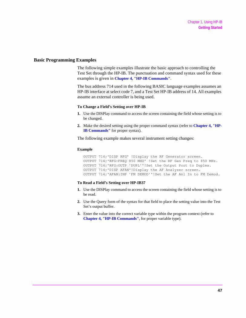
Basic Programming Examples
The following simple examples illustrate the basic approach to controlling the Test Set through the HP-IB. The punctuation and command syntax used for these examples is given in Chapter 4, "HP-IB Commands".
The bus address 714 used in the following BASIC language examples assumes an HP-IB interface at select code 7, and a Test Set HP-IB address of 14. All examples assume an external controller is being used.
To Change a Field’s Setting over HP-IB
1. Use the DISPlay command to access the screen containing the field whose setting is to be changed.
2. Make the desired setting using the proper command syntax (refer to Chapter 4, "HP-IB Commands" for proper syntax).
The following example makes several instrument setting changes:
Example
OUTPUT 714;"DISP RFG" !Display the RF Generator screen.OUTPUT 714;"RFG:FREQ 850 MHZ" !Set the RF Gen Freq to 850 MHz.OUTPUT 714;"RFG:OUTP ’DUPL’"!Set the Output Port to Duplex.OUTPUT 714;"DISP AFAN"!Display the AF Analyzer screen.OUTPUT 714;"AFAN:INP ’FM DEMOD’"!Set the AF Anl In to FM Demod.
To Read a Field’s Setting over HP-IB37
1. Use the DISPlay command to access the screen containing the field whose setting is to be read.
2. Use the Query form of the syntax for that field to place the setting value into the Test Set’s output buffer.
3. Enter the value into the correct variable type within the program context (refer to Chapter 4, "HP-IB Commands", for proper variable type).
47
Chapter 1, Using HP-IBGetting Started
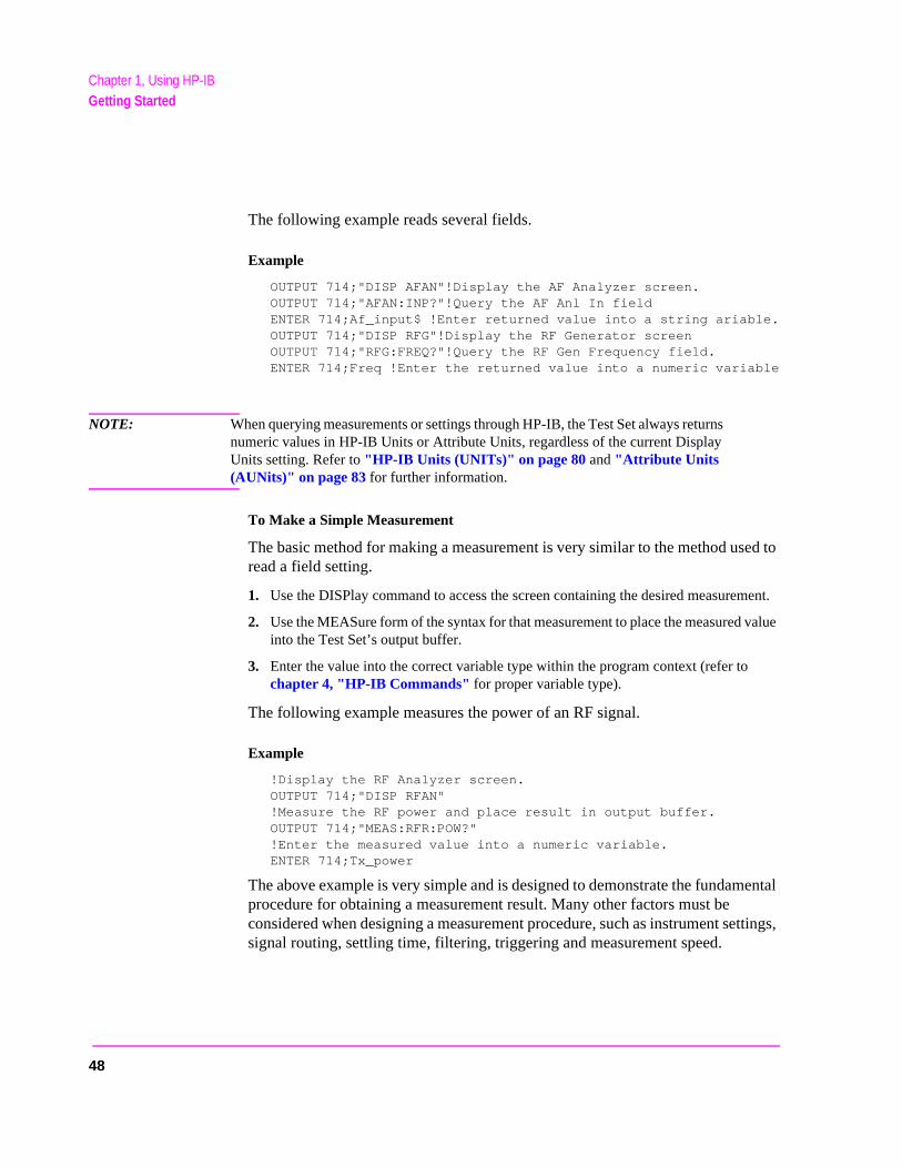
The following example reads several fields.
Example
OUTPUT 714;"DISP AFAN"!Display the AF Analyzer screen.OUTPUT 714;"AFAN:INP?"!Query the AF Anl In fieldENTER 714;Af_input$ !Enter returned value into a string ariable.OUTPUT 714;"DISP RFG"!Display the RF Generator screenOUTPUT 714;"RFG:FREQ?"!Query the RF Gen Frequency field.ENTER 714;Freq !Enter the returned value into a numeric variable
NOTE: When querying measurements or settings through HP-IB, the Test Set always returns numeric values in HP-IB Units or Attribute Units, regardless of the current Display Units setting. Refer to "HP-IB Units (UNITs)" on page 80 and "Attribute Units (AUNits)" on page 83 for further information.
To Make a Simple Measurement
The basic method for making a measurement is very similar to the method used to read a field setting.
1. Use the DISPlay command to access the screen containing the desired measurement.
2. Use the MEASure form of the syntax for that measurement to place the measured value into the Test Set’s output buffer.
3. Enter the value into the correct variable type within the program context (refer to chapter 4, "HP-IB Commands" for proper variable type).
The following example measures the power of an RF signal.
Example
!Display the RF Analyzer screen.OUTPUT 714;"DISP RFAN"!Measure the RF power and place result in output buffer.OUTPUT 714;"MEAS:RFR:POW?"!Enter the measured value into a numeric variable.ENTER 714;Tx_power
The above example is very simple and is designed to demonstrate the fundamental procedure for obtaining a measurement result. Many other factors must be considered when designing a measurement procedure, such as instrument settings, signal routing, settling time, filtering, triggering and measurement speed.
48
Chapter 1, Using HP-IBRemote Operation
Remote Operation
The Test Set can be operated remotely through the Hewlett-Packard Interface Bus (HP-IB). Except as otherwise noted, the Test Set complies with the IEEE 488.1-1987 and IEEE 488.2-1987 Standards. Bus compatibility, programming and data formats are described in the following sections.
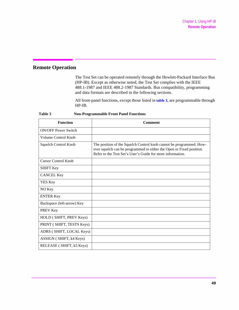
All front-panel functions, except those listed in table 3, are programmable through HP-IB.
Table 3 Non-Programmable Front Panel Functions
Function Comment
ON/OFF Power Switch
Volume Control Knob
Squelch Control Knob The position of the Squelch Control knob cannot be programmed. How-ever squelch can be programmed to either the Open or Fixed position. Refer to the Test Set’s User’s Guide for more information.
Cursor Control Knob
SHIFT Key
CANCEL Key
YES Key
NO Key
ENTER Key
Backspace (left-arrow) Key
PREV Key
HOLD ( SHIFT, PREV Keys)
PRINT ( SHIFT, TESTS Keys)
ADRS ( SHIFT, LOCAL Keys)
ASSIGN ( SHIFT, k4 Keys)
RELEASE ( SHIFT, k5 Keys)
49
Chapter 1, Using HP-IBRemote Operation
Remote Capabilities
Conformance to the IEEE 488.1-1987 Standard
For all IEEE 488.1 functions implemented, the Test Set adheres to the rules and procedures as outlined in that Standard.
Conformance to the IEEE 488.2-1987 Standard
For all IEEE 488.2 functions implemented, the Test Set adheres to the rules and procedures as outlined in that Standard with the exception of the *OPC Common Command. Refer to the *OPC Common Command description.
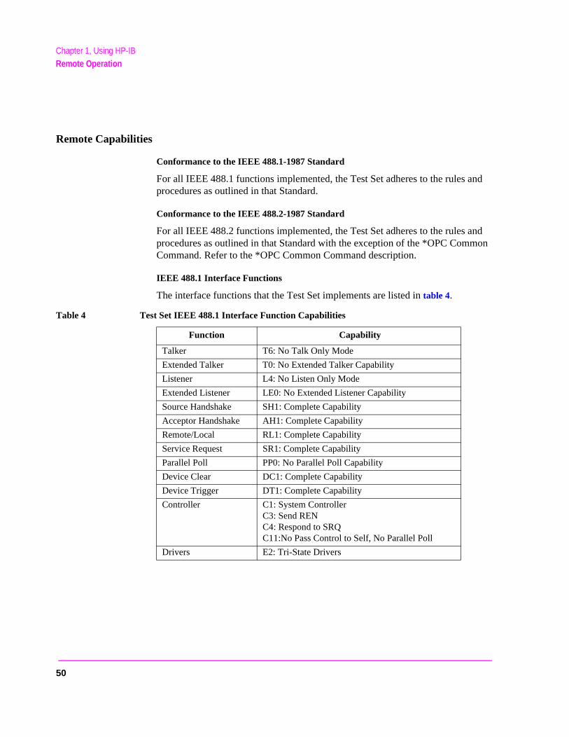
IEEE 488.1 Interface Functions
The interface functions that the Test Set implements are listed in table 4.
Table 4 Test Set IEEE 488.1 Interface Function Capabilities
Function Capability
Talker T6: No Talk Only Mode
Extended Talker T0: No Extended Talker Capability
Listener L4: No Listen Only Mode
Extended Listener LE0: No Extended Listener Capability
Source Handshake SH1: Complete Capability
Acceptor Handshake AH1: Complete Capability
Remote/Local RL1: Complete Capability
Service Request SR1: Complete Capability
Parallel Poll PP0: No Parallel Poll Capability
Device Clear DC1: Complete Capability
Device Trigger DT1: Complete Capability
Controller C1: System ControllerC3: Send RENC4: Respond to SRQC11:No Pass Control to Self, No Parallel Poll
Drivers E2: Tri-State Drivers
50
Chapter 1, Using HP-IBAddressing
an be
for the
the d
Addressing
Factory Set Address
The Test Set’s HP-IB address is set to decimal 14 at the factory. The address cchanged by following the instructions in "Setting the Test Set’s Bus Address" on page 51.
Extended Addressing
Extended addressing (secondary command) capability is not implemented in the Test Set.
Multiple Addressing
Multiple addressing capability is not implemented in the Test Set.
Setting the Test Set’s Bus Address
The Test Set’s HP-IB bus address is set using the HP-IB Adrs field which is located on the I/O CONFIGURE screen. To set the HP-IB bus address; select the I/O CONFIGURE screen and position the cursor next to the HP-IB Adrs field. The address can be set from decimal 0 to 30 using the numeric DATA keys, or by pushing and then rotating the Cursor Control knob. There are no DIP switches setting the HP-IB bus address in the Test Set. The new setting is retained whenTest Set is turned off.
Displaying the Bus Address
The Test Set’s HP-IB bus address can be displayed by pressing and releasing SHIFT key, then the LOCAL key. The address is displayed in the upper left-hancorner of the display screen.
51
Chapter 1, Using HP-IBIEEE 488.1 Remote Interface Message Capabilities
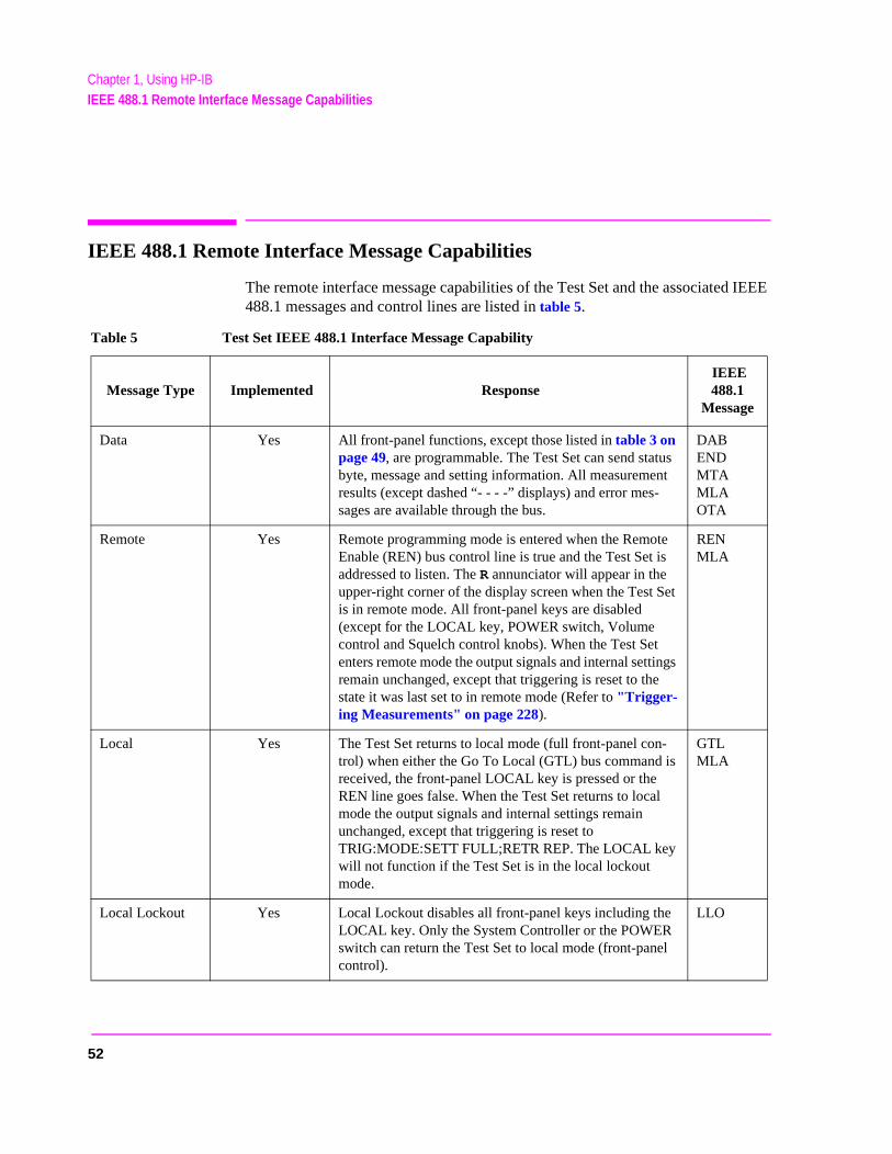
IEEE 488.1 Remote Interface Message Capabilities
The remote interface message capabilities of the Test Set and the associated IEEE 488.1 messages and control lines are listed in table 5.
Table 5 Test Set IEEE 488.1 Interface Message Capability
Message Type Implemented Response IEEE 488.1
Message
Data Yes All front-panel functions, except those listed in table 3 on page 49, are programmable. The Test Set can send status byte, message and setting information. All measurement results (except dashed “- - - -” displays) and error mes-sages are available through the bus.
DABENDMTAMLAOTA
Remote Yes Remote programming mode is entered when the Remote Enable (REN) bus control line is true and the Test Set is addressed to listen. The R annunciator will appear in the upper-right corner of the display screen when the Test Set is in remote mode. All front-panel keys are disabled (except for the LOCAL key, POWER switch, Volume control and Squelch control knobs). When the Test Set enters remote mode the output signals and internal settings remain unchanged, except that triggering is reset to the state it was last set to in remote mode (Refer to "Trigger-ing Measurements" on page 228).
RENMLA
Local Yes The Test Set returns to local mode (full front-panel con-trol) when either the Go To Local (GTL) bus command is received, the front-panel LOCAL key is pressed or the REN line goes false. When the Test Set returns to local mode the output signals and internal settings remain unchanged, except that triggering is reset to TRIG:MODE:SETT FULL;RETR REP. The LOCAL key will not function if the Test Set is in the local lockout mode.
GTLMLA
Local Lockout Yes Local Lockout disables all front-panel keys including the LOCAL key. Only the System Controller or the POWER switch can return the Test Set to local mode (front-panel control).
LLO
52
Chapter 1, Using HP-IBIEEE 488.1 Remote Interface Message Capabilities
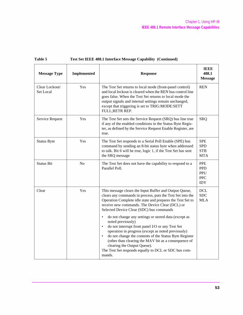
Clear Lockout/Set Local
Yes The Test Set returns to local mode (front-panel control) and local lockout is cleared when the REN bus control line goes false. When the Test Set returns to local mode the output signals and internal settings remain unchanged, except that triggering is set to TRIG:MODE:SETT FULL;RETR REP.
REN
Service Request Yes The Test Set sets the Service Request (SRQ) bus line true if any of the enabled conditions in the Status Byte Regis-ter, as defined by the Service Request Enable Register, are true.
SRQ
Status Byte Yes The Test Set responds to a Serial Poll Enable (SPE) bus command by sending an 8-bit status byte when addressed to talk. Bit 6 will be true, logic 1, if the Test Set has sent the SRQ message
SPE SPDSTBMTA
Status Bit No The Test Set does not have the capability to respond to a Parallel Poll.
PPEPPDPPU PPCIDY
Clear Yes This message clears the Input Buffer and Output Queue, clears any commands in process, puts the Test Set into the Operation Complete idle state and prepares the Test Set to receive new commands. The Device Clear (DCL) or Selected Device Clear (SDC) bus commands
• do not change any settings or stored data (except as noted previously)
• do not interrupt front panel I/O or any Test Set operation in progress (except as noted previously)
• do not change the contents of the Status Byte Register (other than clearing the MAV bit as a consequence of clearing the Output Queue).
The Test Set responds equally to DCL or SDC bus com-mands.
DCLSDC MLA
Table 5 Test Set IEEE 488.1 Interface Message Capability (Continued)
Message Type Implemented Response IEEE 488.1
Message
53
Chapter 1, Using HP-IBIEEE 488.1 Remote Interface Message Capabilities
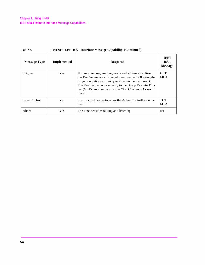
Trigger Yes If in remote programming mode and addressed to listen, the Test Set makes a triggered measurement following the trigger conditions currently in effect in the instrument. The Test Set responds equally to the Group Execute Trig-ger (GET) bus command or the *TRG Common Com-mand.
GET MLA
Take Control Yes The Test Set begins to act as the Active Controller on the bus.
TCTMTA
Abort Yes The Test Set stops talking and listening IFC
Table 5 Test Set IEEE 488.1 Interface Message Capability (Continued)
Message Type Implemented Response IEEE 488.1
Message
54
Chapter 1, Using HP-IBRemote/Local Modes
est the
Data dition hether
ocal
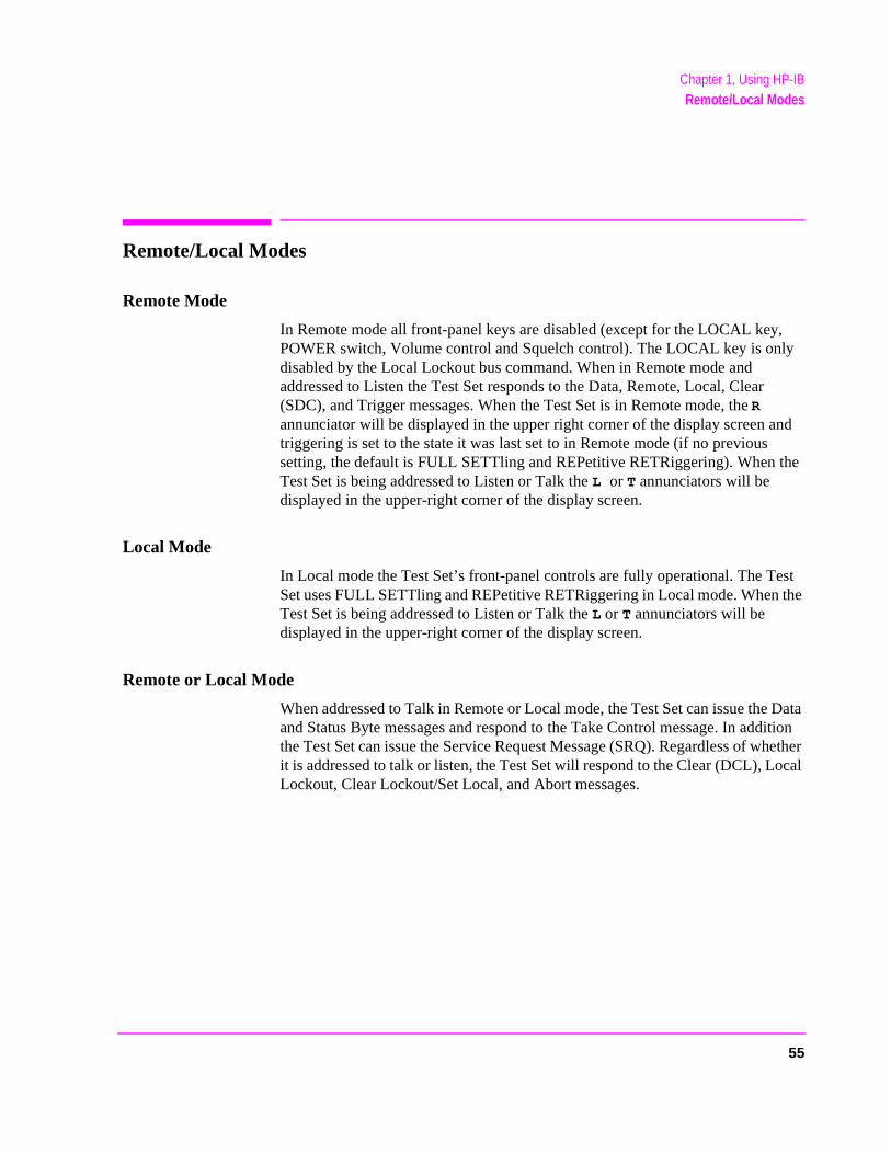
Remote/Local Modes
Remote Mode
In Remote mode all front-panel keys are disabled (except for the LOCAL key, POWER switch, Volume control and Squelch control). The LOCAL key is only disabled by the Local Lockout bus command. When in Remote mode and addressed to Listen the Test Set responds to the Data, Remote, Local, Clear (SDC), and Trigger messages. When the Test Set is in Remote mode, the R annunciator will be displayed in the upper right corner of the display screen and triggering is set to the state it was last set to in Remote mode (if no previous setting, the default is FULL SETTling and REPetitive RETRiggering). When the Test Set is being addressed to Listen or Talk the L or T annunciators will be displayed in the upper-right corner of the display screen.
Local Mode
In Local mode the Test Set’s front-panel controls are fully operational. The TSet uses FULL SETTling and REPetitive RETRiggering in Local mode. WhenTest Set is being addressed to Listen or Talk the L or T annunciators will be displayed in the upper-right corner of the display screen.
Remote or Local Mode
When addressed to Talk in Remote or Local mode, the Test Set can issue theand Status Byte messages and respond to the Take Control message. In adthe Test Set can issue the Service Request Message (SRQ). Regardless of wit is addressed to talk or listen, the Test Set will respond to the Clear (DCL), LLockout, Clear Lockout/Set Local, and Abort messages.
55

Chapter 1, Using HP-IBRemote/Local Modes
Local To Remote Transitions
The Test Set switches from Local to Remote mode upon receipt of the Remote message (REN bus line true and Test Set is addressed to listen). No instrument settings are changed by the transition from Local to Remote mode, but triggering is set to the state it was last set to in Remote mode (if no previous setting, the default is FULL SETTling and REPetitive RETRiggering). The R annunciator in the upper-right corner of the display is turned on.
When the Test Set makes a transition from local to remote mode, all currently active measurements are flagged as invalid causing any currently available measurement results to become unavailable. If the HP-IB trigger mode is :RETR REP then a new measurement cycle is started and measurement results will be available for all active measurements when valid results have been obtained. If the HP-IB trigger mode is :RETR SING then a measurement cycle must be started by issuing a trigger event. Refer to "Triggering Measurements" on page 228 for more information.
Remote To Local Transitions
The Test Set switches from Remote to Local mode upon receipt of the Local message (Go To Local bus message is sent and Test Set is addressed to listen) or receipt of the Clear Lockout/Set Local message (REN bus line false). No instrument settings are changed by the transition from Remote to Local mode, but triggering is reset to FULL SETTling and REPetitive RETRiggering. The R annunciator in the upper right corner of the display is turned off.
If it is not in Local Lockout mode the Test Set switches from Remote to Local mode whenever the front-panel LOCAL key is pressed.
If the Test Set was in Local Lockout mode when the Local message was received, front-panel control is returned, but Local Lockout mode is not cleared. Unless the Test Set receives the Clear Lockout/Set Local message, the Test Set will still be in Local Lockout mode the next time it goes to the Remote mode.
56
Chapter 1, Using HP-IBRemote/Local Modes
Local Lockout
The Local Lockout mode disables the front-panel LOCAL key and allows return to Local mode only by commands from the System Controller (Clear Lockout/Set Local message).
When a data transmission to the Test Set is interrupted, which can happen if the LOCAL key is pressed, the data being transmitted may be lost. This can leave the Test Set in an unknown state. The Local Lockout mode prevents loss of data or system control due to someone unintentionally pressing front-panel keys.
NOTE: Return to Local mode can also be accomplished by setting the POWER switch to OFF andback to ON. However, returning to Local mode in this way has the following disadvantages:
1. It defeats the purpose of the Local Lockout mode in that the Active Controller will losecontrol of the test set.
2. Instrument configuration is reset to the power up condition thereby losing theinstrument configuration set by the Active Controller.
Clear Lockout/Set Local
The Test Set returns to Local mode when it receives the Clear Lockout/Set Local message. No instrument settings are changed by the transition from Remote mode with Local Lockout to Local mode but triggering is reset to FULL SETTling and REPetitive RETRiggering.
57

Chapter 1, Using HP-IBRemote/Local Modes
58
2
Methods For Reading Measurement Results
59

Chapter 2, Methods For Reading Measurement ResultsBackground
the he
e o
uence t.
Background
One of the most common remote user interface operations performed on anTest Set is to query and read a measurement result. Generally, this operation is accomplished by sending the query command to the Test Set, followed immediately by a request to read the requested measurement result. Using Hewlett-Packard Rocky Mountain BASIC (RMB) language, this operation would be written using the OUTPUT and ENTER command as follows:
OUTPUT 714;"MEAS:RFR:POW?"
ENTER 714;Power
Using this programming structure, the control program will stay on the ENTER statement until it is satisfied - that is - until the Test Set has returned the requested measurement result. This structure works correctly as long as the Test Set returns a valid measurement result. If, for some reason, the Test Set does not return a measurement result, the control program becomes “hung” on the ENTER statement and program execution effectively stops.
In order to prevent the control program from becoming “hung” programmers usually enclose the operation with some form of timeout function. The form oftimeout will of course depend upon the programming language being used. Tpurpose of the timeout is to specify a fixed amount of time that the control program will wait for the Test Set to return the requested result. After this timhas expired the control program will abandon the ENTER statement and try ttake some corrective action to regain control of the Test Set.
If the control program does not send the proper commands in the proper seqwhen trying to regain control of the Test Set, unexpected operation will resulWhen this condition is encountered, power must be cycled on the Test Set toregain control.
60

Chapter 2, Methods For Reading Measurement ResultsBackground
HP-IB
egain
ent
has time-
Test
he
This situation can be avoided entirely by:
1. sending a Selected Device Clear (SDC) interface message to put the Test Set’s subsystem into a known state.
2. sending a command to terminate the requested measurement cycle.
These commands issued in this order will allow the control program to regain control of the Test Set. Any other sequence of commands will result in unexpected operation.
The following programs demonstrate a recommended technique for querying and entering data from the Test Set. This technique will prevent the Test Set from getting into a ‘hung’ state such that power must be cycled on the Test Set to rmanual or programmatic control.
There are a variety of programming constructs which can be used to implemthis technique. In the programming examples presented, a function call is implemented which returns a numeric measurement result. The function call two pass parameters; the query command (passed as a quoted string) and aout value (passed as a integer number).
The time-out value represents how long you want to wait, in seconds, for theSet to return a valid measurement result. If a valid measurement result is notreturned by the Test Set within the time-out value, the function returns a verylarge number. The calling program can check the value and take appropriateaction.
The program examples are written so as to be self-explanatory. In practice, tlength of: variable names, line labels, function names, etc., will be implementation dependent.
61

Chapter 2, Methods For Reading Measurement ResultsHP BASIC ‘ON TIMEOUT’ Example Program
the nt
trate mpled
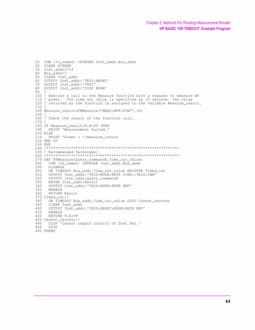
HP BASIC ‘ON TIMEOUT’ Example Program
The following example program demonstrates a recommended technique which can be utilized in situations where a measurement result timeout value of 32.767 seconds or less is adequate. In the HP RMB language, the timeout parameter for the ON TIMEOUT command has a maximum value of 32.767 seconds. If a timeout value of greater than 32.767 seconds is required refer to the HP BASIC ‘MAV’ Bit Example Program.
The measurement result timeout value is defined to mean the amount of timecontrol program is willing to wait for the Test Set to return a valid measuremeresult to the control program.
Lines 10 thru 230 in this example set up a measurement situation to demonsthe use of the recommended technique. The recommended technique is exain the Measure Function.
NOTE: Lines 50 and 60 should be included in the beginning of all control program. These lines arerequired to ensure that the Test Set is properly reset. This covers the case where the programwas previously run and was stopped with the Test Set in an error condition.
62
Chapter 2, Methods For Reading Measurement ResultsHP BASIC ‘ON TIMEOUT’ Example Program
10 COM /Io_names/ INTEGER Inst_addr,Bus_addr20 CLEAR SCREEN30 Inst_addr=71440 Bus_addr=750 CLEAR Inst_addr60 OUTPUT Inst_addr;"TRIG:ABORT"70 OUTPUT Inst_addr;"*RST"80 OUTPUT Inst_addr;"DISP RFAN"90 !100 ! Execute a call to the Measure function with a request to measure RF110 ! power. The time out value is specified as 10 seconds. The value120 ! returned by the function is assigned to the variable Measure_result.130 !140 Measure_result=FNMeasure("MEAS:RFR:POW?",10)150 !160 ! Check the result of the function call.170 !180 IF Measure_result=9.E+99 THEN 190 PRINT "Measurement failed."200 ELSE210 PRINT "Power = ";Measure_result220 END IF230 END240 !***********************************************************250 ! Recommended Technique:260 !***********************************************************270 DEF FNMeasure(Query_command$,Time_out_value)280 COM /Io_names/ INTEGER Inst_addr,Bus_addr290 DISABLE 300 ON TIMEOUT Bus_addr,Time_out_value RECOVER Timed_out310 OUTPUT Inst_addr;"TRIG:MODE:RETR SING;:TRIG:IMM"320 OUTPUT Inst_addr;Query_command$330 ENTER Inst_addr;Result340 OUTPUT Inst_addr;"TRIG:MODE:RETR REP"350 ENABLE360 RETURN Result370 Timed_out:!380 ON TIMEOUT Bus_addr,Time_out_value GOTO Cannot_recover390 CLEAR Inst_addr400 OUTPUT Inst_addr;"TRIG:ABORT;MODE:RETR REP"410 ENABLE 420 RETURN 9.E+99430 Cannot_recover:!440 DISP "Cannot regain control of Test Set."450 STOP460 FNEND
63
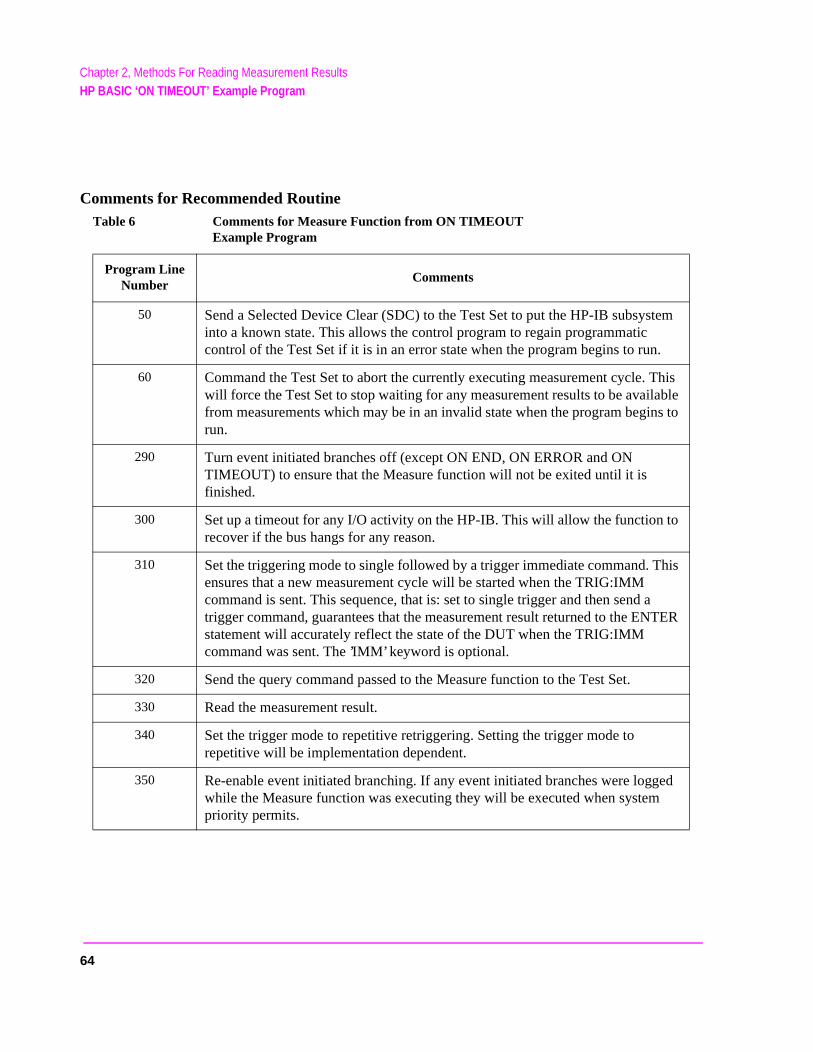
Chapter 2, Methods For Reading Measurement ResultsHP BASIC ‘ON TIMEOUT’ Example Program
Comments for Recommended RoutineTable 6 Comments for Measure Function from ON TIMEOUT
Example Program
Program Line Number
Comments
50 Send a Selected Device Clear (SDC) to the Test Set to put the HP-IB subsystem into a known state. This allows the control program to regain programmatic control of the Test Set if it is in an error state when the program begins to run.
60 Command the Test Set to abort the currently executing measurement cycle. This will force the Test Set to stop waiting for any measurement results to be available from measurements which may be in an invalid state when the program begins to run.
290 Turn event initiated branches off (except ON END, ON ERROR and ON TIMEOUT) to ensure that the Measure function will not be exited until it is finished.
300 Set up a timeout for any I/O activity on the HP-IB. This will allow the function to recover if the bus hangs for any reason.
310 Set the triggering mode to single followed by a trigger immediate command. This ensures that a new measurement cycle will be started when the TRIG:IMM command is sent. This sequence, that is: set to single trigger and then send a trigger command, guarantees that the measurement result returned to the ENTER statement will accurately reflect the state of the DUT when the TRIG:IMM command was sent. The ’IMM’ keyword is optional.
320 Send the query command passed to the Measure function to the Test Set.
330 Read the measurement result.
340 Set the trigger mode to repetitive retriggering. Setting the trigger mode to repetitive will be implementation dependent.
350 Re-enable event initiated branching. If any event initiated branches were logged while the Measure function was executing they will be executed when system priority permits.
64
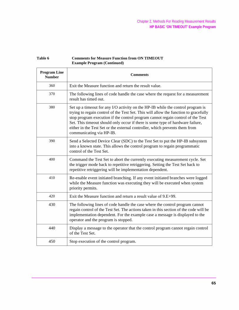
Chapter 2, Methods For Reading Measurement ResultsHP BASIC ‘ON TIMEOUT’ Example Program
360 Exit the Measure function and return the result value.
370 The following lines of code handle the case where the request for a measurement result has timed out.
380 Set up a timeout for any I/O activity on the HP-IB while the control program is trying to regain control of the Test Set. This will allow the function to gracefully stop program execution if the control program cannot regain control of the Test Set. This timeout should only occur if there is some type of hardware failure, either in the Test Set or the external controller, which prevents them from communicating via HP-IB.
390 Send a Selected Device Clear (SDC) to the Test Set to put the HP-IB subsystem into a known state. This allows the control program to regain programmatic control of the Test Set.
400 Command the Test Set to abort the currently executing measurement cycle. Set the trigger mode back to repetitive retriggering. Setting the Test Set back to repetitive retriggering will be implementation dependent.
410 Re-enable event initiated branching. If any event initiated branches were logged while the Measure function was executing they will be executed when system priority permits.
420 Exit the Measure function and return a result value of 9.E+99.
430 The following lines of code handle the case where the control program cannot regain control of the Test Set. The actions taken in this section of the code will be implementation dependent. For the example case a message is displayed to the operator and the program is stopped.
440 Display a message to the operator that the control program cannot regain control of the Test Set.
450 Stop execution of the control program.
Table 6 Comments for Measure Function from ON TIMEOUT Example Program (Continued)
Program Line Number
Comments
65

Chapter 2, Methods For Reading Measurement ResultsHP BASIC ‘MAV’ Example Program
HP BASIC ‘MAV’ Example Program
The following HP RMB example program demonstrates a technique which can be used in situations where a 32.767 measurement result timeout value is not adequate.
Measurement result timeout value is defined to mean the amount of time the control program is willing to wait for the Test Set to return a valid measurement result to the control program.
The technique uses the MAV (Message Available) bit in the Test Set’s HP-IB Status Byte to determine when there is data in the Output Queue. A polling loop is used to query the Status byte. The timeout duration for returning the measurement result is handled by the polling loop. An HP-IB interface activity timeout is also set up to handle time-outs resulting from problems with the HP-IB interface.
Lines 10 thru 230 in this example set up a measurement situation to demonstrate the use of the recommended technique. The recommended technique is exampled in the Measure Function.
NOTE: Lines 50 and 60 should be included in the beginning of all control program. These lines arerequired to ensure that the Test Set is properly reset. This covers the case where the programwas previously run and was stopped with the Test Set in an error condition.
66
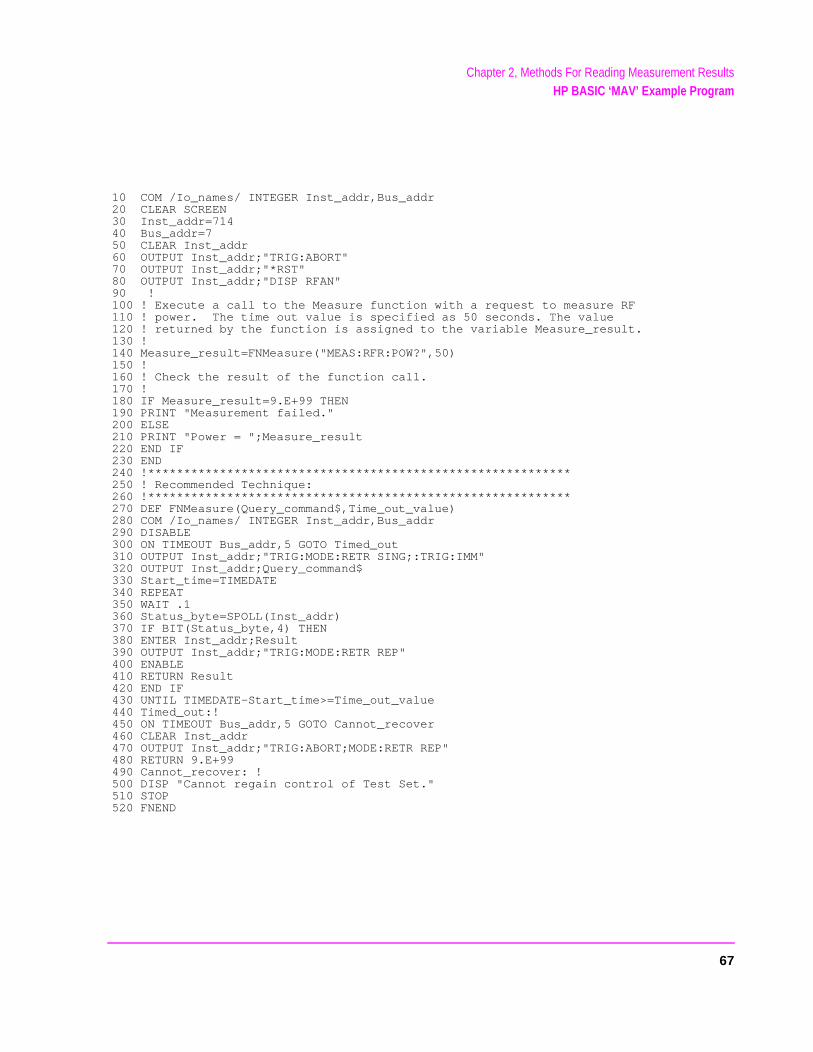
Chapter 2, Methods For Reading Measurement ResultsHP BASIC ‘MAV’ Example Program
10 COM /Io_names/ INTEGER Inst_addr,Bus_addr20 CLEAR SCREEN30 Inst_addr=71440 Bus_addr=750 CLEAR Inst_addr60 OUTPUT Inst_addr;"TRIG:ABORT"70 OUTPUT Inst_addr;"*RST"80 OUTPUT Inst_addr;"DISP RFAN"90 !100 ! Execute a call to the Measure function with a request to measure RF110 ! power. The time out value is specified as 50 seconds. The value120 ! returned by the function is assigned to the variable Measure_result.130 !140 Measure_result=FNMeasure("MEAS:RFR:POW?",50)150 !160 ! Check the result of the function call.170 !180 IF Measure_result=9.E+99 THEN 190 PRINT "Measurement failed."200 ELSE210 PRINT "Power = ";Measure_result220 END IF230 END240 !***********************************************************250 ! Recommended Technique:260 !***********************************************************270 DEF FNMeasure(Query_command$,Time_out_value)280 COM /Io_names/ INTEGER Inst_addr,Bus_addr290 DISABLE 300 ON TIMEOUT Bus_addr,5 GOTO Timed_out310 OUTPUT Inst_addr;"TRIG:MODE:RETR SING;:TRIG:IMM"320 OUTPUT Inst_addr;Query_command$330 Start_time=TIMEDATE340 REPEAT350 WAIT .1360 Status_byte=SPOLL(Inst_addr)370 IF BIT(Status_byte,4) THEN 380 ENTER Inst_addr;Result390 OUTPUT Inst_addr;"TRIG:MODE:RETR REP"400 ENABLE410 RETURN Result420 END IF430 UNTIL TIMEDATE-Start_time>=Time_out_value440 Timed_out:!450 ON TIMEOUT Bus_addr,5 GOTO Cannot_recover460 CLEAR Inst_addr470 OUTPUT Inst_addr;"TRIG:ABORT;MODE:RETR REP"480 RETURN 9.E+99490 Cannot_recover: !500 DISP "Cannot regain control of Test Set."510 STOP520 FNEND
67
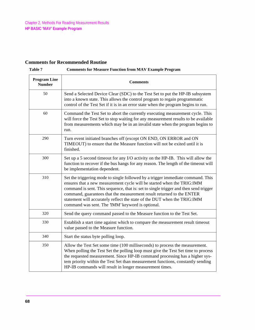
Chapter 2, Methods For Reading Measurement ResultsHP BASIC ‘MAV’ Example Program
Comments for Recommended RoutineTable 7 Comments for Measure Function from MAV Example Program
Program Line Number
Comments
50 Send a Selected Device Clear (SDC) to the Test Set to put the HP-IB subsystem into a known state. This allows the control program to regain programmatic control of the Test Set if it is in an error state when the program begins to run.
60 Command the Test Set to abort the currently executing measurement cycle. This will force the Test Set to stop waiting for any measurement results to be available from measurements which may be in an invalid state when the program begins to run.
290 Turn event initiated branches off (except ON END, ON ERROR and ON TIMEOUT) to ensure that the Measure function will not be exited until it is finished.
300 Set up a 5 second timeout for any I/O activity on the HP-IB. This will allow the function to recover if the bus hangs for any reason. The length of the timeout will be implementation dependent.
310 Set the triggering mode to single followed by a trigger immediate command. This ensures that a new measurement cycle will be started when the TRIG:IMM command is sent. This sequence, that is: set to single trigger and then send trigger command, guarantees that the measurement result returned to the ENTER statement will accurately reflect the state of the DUT when the TRIG:IMM command was sent. The ’IMM’ keyword is optional.
320 Send the query command passed to the Measure function to the Test Set.
330 Establish a start time against which to compare the measurement result timeout value passed to the Measure function.
340 Start the status byte polling loop.
350 Allow the Test Set some time (100 milliseconds) to process the measurement. When polling the Test Set the polling loop must give the Test Set time to process the requested measurement. Since HP-IB command processing has a higher sys-tem priority within the Test Set than measurement functions, constantly sending HP-IB commands will result in longer measurement times.
68
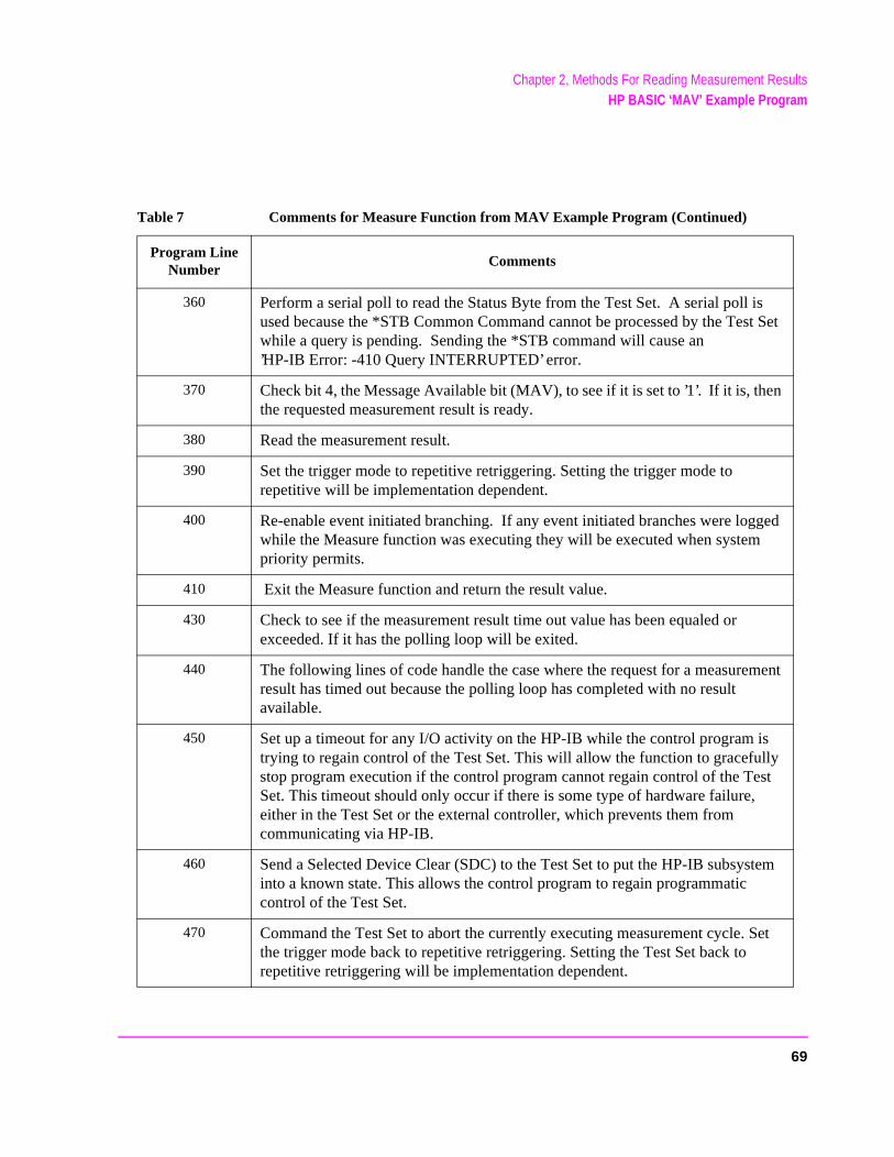
Chapter 2, Methods For Reading Measurement ResultsHP BASIC ‘MAV’ Example Program
360 Perform a serial poll to read the Status Byte from the Test Set. A serial poll is used because the *STB Common Command cannot be processed by the Test Set while a query is pending. Sending the *STB command will cause an’HP-IB Error: -410 Query INTERRUPTED’ error.
370 Check bit 4, the Message Available bit (MAV), to see if it is set to ’1’. If it is, then the requested measurement result is ready.
380 Read the measurement result.
390 Set the trigger mode to repetitive retriggering. Setting the trigger mode to repetitive will be implementation dependent.
400 Re-enable event initiated branching. If any event initiated branches were logged while the Measure function was executing they will be executed when system priority permits.
410 Exit the Measure function and return the result value.
430 Check to see if the measurement result time out value has been equaled or exceeded. If it has the polling loop will be exited.
440 The following lines of code handle the case where the request for a measurement result has timed out because the polling loop has completed with no result available.
450 Set up a timeout for any I/O activity on the HP-IB while the control program is trying to regain control of the Test Set. This will allow the function to gracefully stop program execution if the control program cannot regain control of the Test Set. This timeout should only occur if there is some type of hardware failure, either in the Test Set or the external controller, which prevents them from communicating via HP-IB.
460 Send a Selected Device Clear (SDC) to the Test Set to put the HP-IB subsystem into a known state. This allows the control program to regain programmatic control of the Test Set.
470 Command the Test Set to abort the currently executing measurement cycle. Set the trigger mode back to repetitive retriggering. Setting the Test Set back to repetitive retriggering will be implementation dependent.
Table 7 Comments for Measure Function from MAV Example Program (Continued)
Program Line Number
Comments
69
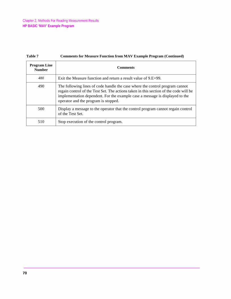
Chapter 2, Methods For Reading Measurement ResultsHP BASIC ‘MAV’ Example Program
480 Exit the Measure function and return a result value of 9.E+99.
490 The following lines of code handle the case where the control program cannot regain control of the Test Set. The actions taken in this section of the code will be implementation dependent. For the example case a message is displayed to the operator and the program is stopped.
500 Display a message to the operator that the control program cannot regain control of the Test Set.
510 Stop execution of the control program.
Table 7 Comments for Measure Function from MAV Example Program (Continued)
Program Line Number
Comments
70
3
HP-IB Command Guidelines
71
Chapter 3, HP-IB Command GuidelinesSequential and Overlapped Commands
l to
t B the ime efer
Sequential and Overlapped Commands
IEEE 488.2 makes the distinction between sequential and overlapped commands. Sequential commands complete their task before execution of the next command can begin. Overlapped commands can run concurrently, that is, a command following an overlapped command may begin execution while the overlapped command is still in progress. All commands in the Test Set are sequential.
The processing architecture of the Test Set allows it to accept commands through the HP-IB while it is executing commands already parsed into its command buffer. While this may appear to be overlapped, commands are always executed sequentially in the order received.
The process of executing a command can be divided into three steps:
1. Command is accepted from HP-IB and checked for proper structure and parameters.2. Commands is sent to instrument hardware.3. Instrument hardware fully responds after some time, ∆t.
For example, in programming the Test Set’s RF Signal Generator it takes < 150 ms after receipt of the frequency setting command for the output signabe within 100 Hz of the desired frequency. In the Test Set, commands are considered to have “completed their task” at the end of step 2. In manual operation all displayed measurement results take into account the instrumenhardware’s response time. When programming measurements through HP-ITriggering mode selected will determine whether the instrument’s response tis accounted for automatically or if the control program must account for it. Rto "Triggering Measurements" on page 228 for a discussion of the different Triggermodes available in the Test Set and their affect on measurement results.
72
Chapter 3, HP-IB Command GuidelinesGuidelines for Operation
Guidelines for Operation
The following topics discuss rules and guidelines for controlling the Test Set through HP-IB.
Command Names
All command names of more than four characters have an alternate abbreviated form using only upper case letters and, in some cases, a single numeral. The commands are not case sensitive. Upper and lower case characters can be used for all commands.
For example, to set the destination of AF Generator 1 to Audio Out, any of the following command strings are valid:
AFGENERATOR1:DESTINATION ’AUDIO OUT’ orafgenerator1:destination ’audio out’ orafg1:dest ’audio out’ orAFG1:DEST ’AUDIO OUT’ orAfg1:Dest ’Audio oUT’
73

Chapter 3, HP-IB Command GuidelinesGuidelines for Operation
ectr
lue in
Command Punctuation
NOTE: Programming Language Considerations. The punctuation rules for the Test Set’s HP-IB commands conform to the IEEE 488.2 standard. It is possible that someprogramming languages used on external controllers may not accept some of thpunctuation requirements. It is therefore necessary that the equivalent form of the correpunctuation, as defined by the language, be used for HP-IB operation. Impropepunctuation will results in HP-IB Error: -102 Syntax Error.
Using Quotes for String Entries
Quotation marks ’ and " are used to select a non-numeric field setting. The value is entered into the command line as a quoted alphanumeric string.
Quotes are used with all Underlined (toggling) and One-of-many (menu choice) fields. (See “Changing A Field’s Setting” in chapter 1 of the HP 8921A User’s Guide for field type descriptions.)
For example, to set the RF Generator’s Output Port field to Dupl (duplex), the Dupl would be entered into the command string.
RFG:OUTP ’Dupl’ orRFG:OUTP "Dupl"
Using Spaces
When changing a field’s setting, a space must always precede the setting vathe command string, regardless of the field type (command<space>value).
RFG:FREQ<space>850MHZRFG:ATT<space>’OFF’
74

Chapter 3, HP-IB Command GuidelinesGuidelines for Operation
and
d
nd.
Using Colons to Separate Commands
The HP-IB command syntax is structured using a control hierarchy that is analogous to manual operation.
The control hierarchy for making a manual instrument setting using the front-panel controls is as follows: first the screen is accessed, then the desired field is selected, then the appropriate setting is made. HP-IB commands use the same hierarchy. The colon (:) is used to separate the different levels of the command hierarchy.
For example, to set the AF Analyzer input gain to 40 dB, the following command syntax would be used:
DISP AFANAFAN:INP:GAIN ’40 dB’
Using the Semicolon to Output Multiple Commands
Multiple commands can be output from one program line by separating the commands with a semicolon (;). The semicolon tells the Test Set’s HP-IB command parser to back up one level of hierarchy and accept the next commat the same level as the previous command.
For example, on one command line, it is possible to
1. access the AF ANALYZER screen, 2. set the AF Analyzer’s Input to AM Demod 3. set Filter 1 to 300 Hz HPF 4. set Filter 2 to 3kHz LPF
DISP AFAN;AFAN:INP ’AM DEMOD’;FILT1 ’300Hz HPF’;FILT2 ’3kHz LPF’
The semicolon after the “DISP AFAN” command tells the Test Set’s HP-IB command parser that the next command is at the same level in the commanhierarchy as the display command. Similarly, the semicolon after the INP 'AMDEMOD' command tells the command parser that the next command (FILT1'300Hz HPF') is at the same command level as the INP 'AM DEMOD' comma
75

Chapter 3, HP-IB Command GuidelinesGuidelines for Operation
e AF
estion the
ried
Using the Semicolon and Colon to Output Multiple Commands
A semicolon followed by a colon (;:) tells the HP-IB command parser that the next command is at the top level of the command hierarchy. This allows commands from different instruments to be output on one command line. The following example sets the RF Analyzer’s tune frequency to 850 MHz, and then sets thAnalyzer’s input to FM Demod.
RFAN:FREQ 850MHZ;:AFAN:INP ’FM DEMOD’
Using Question Marks to Query Setting or Measurement Fields
The question mark (?) is used to query (read-back) an instrument setting or measurement value. To generate the query form of a command, place the qumark immediately after the command. Queried information must be read intoproper variable type within the program context before it can be displayed, printed, or used as a numeric value in the program.
Queried information is returned in the same format used to set the value: quenumeric fields return numeric data; quoted string fields return quoted string information.
For example, the following BASIC language program statements query the current setting of the AFGen 1 To field:
!Query the AFGen1 To fieldOUTPUT 714;"AFG1:DEST?"!Enter queried value into a string variable.ENTER 714;Afg1_to$
76

Chapter 3, HP-IB Command GuidelinesGuidelines for Operation
g y
nt
ric
d z
the o
d
Specifying Units-of-Measure for Settings and Measurement Results
Numeric settings and measurement results in the Test Set can be displayed using one or more units-of-measure (V, mV, mV, Hz, kHz, MHz…). When operatinthe Test Set manually, the units-of-measure can be easily changed to displameasurement results and field settings in the most convenient format. HP-IBoperation is similar to manual operation in that the units-of-measure used to display numeric data can be programmatically changed to the most convenieform.
NOTE: When querying measurements or settings through HP-IB, the Test Set always returns numericvalues in HP-IB Units or Attribute Units, regardless of the current Display Units setting. Referto "HP-IB Units (UNITs)" on page 80 and "Attribute Units (AUNits)" on page 83 forfurther information.
There are three sets of units-of-measure used in the Test Set: Display Units,HP-IB Units, and Attribute Units. Writing correct HP-IB programs requires anunderstanding of how the Test Set deals with these different sets of units-of-measure.
Display Units (DUNits)
Display Units are the units-of-measure used by the Test Set to display numedata (field settings and measurement results) on the front-panel CRT display. For example, the RF Generator’s frequency can be displayed in Hz, kHz, MHz anGHz. Similarly, the measured TX Frequency can be displayed in Hz, kHz, MHand GHz.
When evaluating an entered value for a numeric field, the Test Set interpretsdata it receives in terms of the Display Units currently set. For example, if theDisplay Units for the RF Gen Freq field are set to GHz and the operator tries tenter 500 into the field, an Input value out of range error is generated since the Test Set interpreted the value as 500 GHz which is outside the valifrequency range of the Test Set.
77
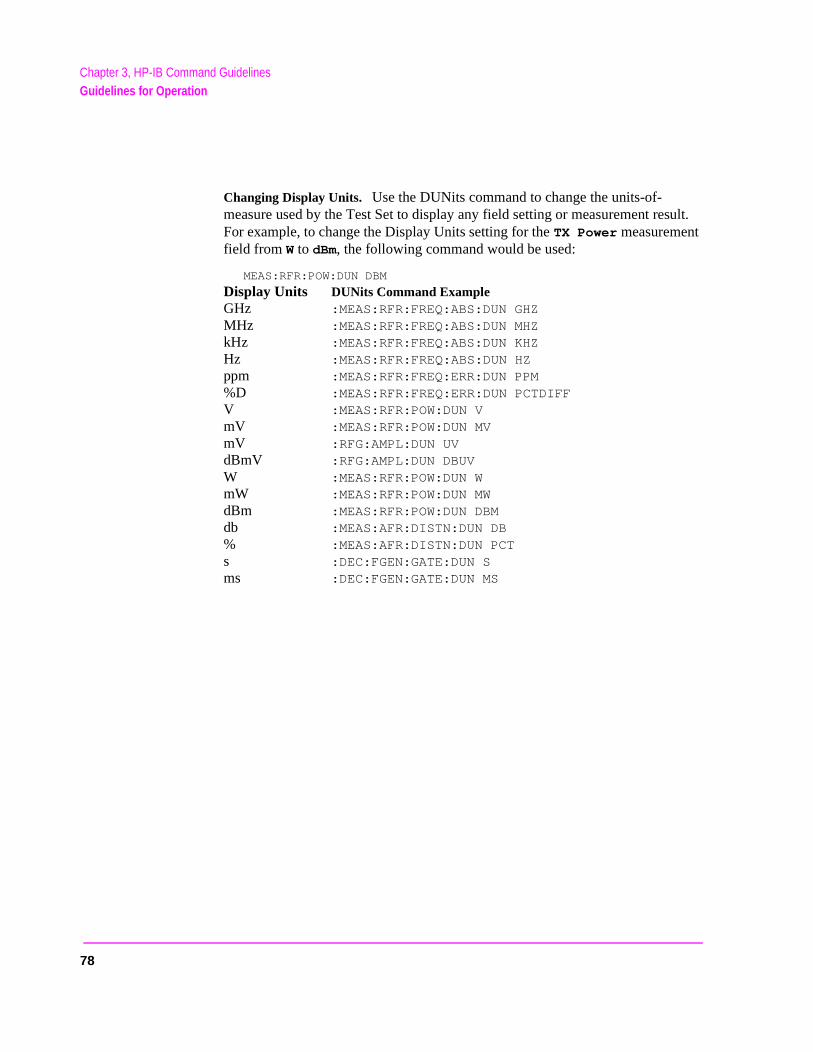
Chapter 3, HP-IB Command GuidelinesGuidelines for Operation
Changing Display Units. Use the DUNits command to change the units-of-measure used by the Test Set to display any field setting or measurement result. For example, to change the Display Units setting for the TX Power measurement field from W to dBm, the following command would be used:
MEAS:RFR:POW:DUN DBM
Display Units DUNits Command ExampleGHz :MEAS:RFR:FREQ:ABS:DUN GHZ MHz :MEAS:RFR:FREQ:ABS:DUN MHZ kHz :MEAS:RFR:FREQ:ABS:DUN KHZ Hz :MEAS:RFR:FREQ:ABS:DUN HZ ppm :MEAS:RFR:FREQ:ERR:DUN PPM %D :MEAS:RFR:FREQ:ERR:DUN PCTDIFF V :MEAS:RFR:POW:DUN V mV :MEAS:RFR:POW:DUN MV mV :RFG:AMPL:DUN UV dBmV :RFG:AMPL:DUN DBUV W :MEAS:RFR:POW:DUN W mW :MEAS:RFR:POW:DUN MW dBm :MEAS:RFR:POW:DUN DBM db :MEAS:AFR:DISTN:DUN DB % :MEAS:AFR:DISTN:DUN PCT s :DEC:FGEN:GATE:DUN S ms :DEC:FGEN:GATE:DUN MS
78
Chapter 3, HP-IB Command GuidelinesGuidelines for Operation
ont-
UV
et
lid
ld’s
t
Reading Back Display Units Setting. Use the Display Units query command, DUNits?, to read back the current Display Units setting. For example, the following BASIC language program statements query the current Display Units setting for the TX Power measurement:
!Query Display Units setting for TX Power measurement.OUTPUT 714;"MEAS:RFR:POW:DUNits?"!Enter the returned value into a string variable.ENTER 714;A$
The returned units-of-measure will be whatever is shown on the Test Set’s frpanel display for the TX Power measurement: dBm, V, mV, dBuV, or W. All returned characters are in upper case. For example, if dBuV is displayed, DBis returned.
Guidelines for Display Units
• When querying a field’s setting or measurement result through HP-IB, the Test Salways returns numeric values in HP-IB Units or Attribute Units, regardless of thefield’s current Display Units setting.
• The Display Units for a field’s setting or measurement result can be set to any vaunit-of-measure, regardless of the field’s HP-IB Units or Attribute Units.
• The Display Units setting for a field’s setting is not affected when changing the fievalue through HP-IB.
For example, if the AFGen1 Freq Display Units are set to kHz, and the commandAFG1:FREQ 10 HZ is sent to change AFGen1’s frequency to 10 Hz, the Test Sedisplays 0.0100 kHz; not 10 Hz.
79
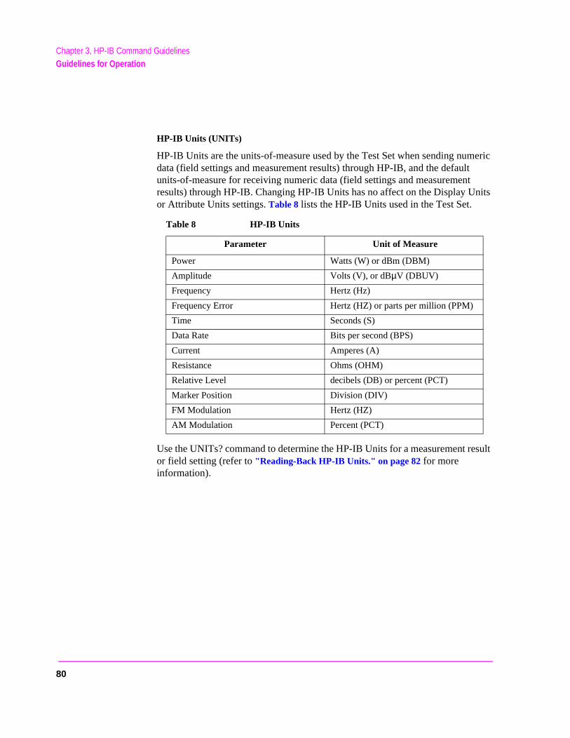
Chapter 3, HP-IB Command GuidelinesGuidelines for Operation
HP-IB Units (UNITs)
HP-IB Units are the units-of-measure used by the Test Set when sending numeric data (field settings and measurement results) through HP-IB, and the default units-of-measure for receiving numeric data (field settings and measurement results) through HP-IB. Changing HP-IB Units has no affect on the Display Units or Attribute Units settings. Table 8 lists the HP-IB Units used in the Test Set.
Use the UNITs? command to determine the HP-IB Units for a measurement result or field setting (refer to "Reading-Back HP-IB Units." on page 82 for more information).
Table 8 HP-IB Units
Parameter Unit of Measure
Power Watts (W) or dBm (DBM)
Amplitude Volts (V), or dBµV (DBUV)
Frequency Hertz (Hz)
Frequency Error Hertz (HZ) or parts per million (PPM)
Time Seconds (S)
Data Rate Bits per second (BPS)
Current Amperes (A)
Resistance Ohms (OHM)
Relative Level decibels (DB) or percent (PCT)
Marker Position Division (DIV)
FM Modulation Hertz (HZ)
AM Modulation Percent (PCT)
80
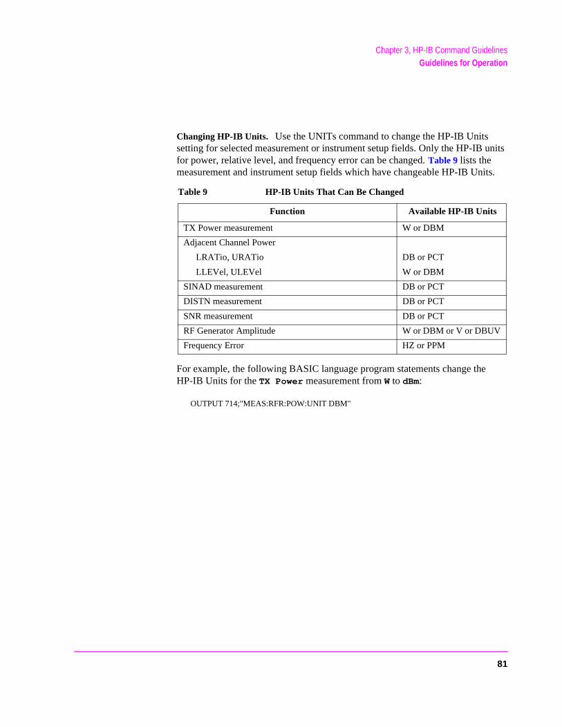
Chapter 3, HP-IB Command GuidelinesGuidelines for Operation
Changing HP-IB Units. Use the UNITs command to change the HP-IB Units setting for selected measurement or instrument setup fields. Only the HP-IB units for power, relative level, and frequency error can be changed. Table 9 lists the measurement and instrument setup fields which have changeable HP-IB Units.
For example, the following BASIC language program statements change the HP-IB Units for the TX Power measurement from W to dBm:
OUTPUT 714;"MEAS:RFR:POW:UNIT DBM"
Table 9 HP-IB Units That Can Be Changed
Function Available HP-IB Units
TX Power measurement W or DBM
Adjacent Channel Power
LRATio, URATio DB or PCT
LLEVel, ULEVel W or DBM
SINAD measurement DB or PCT
DISTN measurement DB or PCT
SNR measurement DB or PCT
RF Generator Amplitude W or DBM or V or DBUV
Frequency Error HZ or PPM
81
Chapter 3, HP-IB Command GuidelinesGuidelines for Operation
rent
t will
turns eric
z
one
Reading-Back HP-IB Units. Use the UNITs? command to read back the current HP-IB Units setting for a measurement or instrument setup field. For example, the following BASIC language program statements read back the current HP-IB Units setting for the TX Power measurement:
!Query the current HP-IB Units setting for TX Power.OUTPUT 714;"MEAS:RFR:POW:UNIT?"!Enter the returned value into a string variable.ENTER 714;A$
Guidelines for HP-IB Units
• When setting the value of a numeric field (such as AFGen1 Freq), any non–HP-IB Unit unit-of-measure must be specified in the command string, otherwise the curHP-IB Unit is assumed by the Test Set.
For example, if the command RFG:FREQ 900 is sent through HP-IB, the Test Seinterpret the data as 900 Hz, since HZ is the HP-IB Unit for frequency. This wouldresult in an Input value out of range error. Sending the command RFG:FREQ 900 MHZ would set the value to 900 MHz.
• When querying measurements or settings through HP-IB, the Test Set always renumeric values in HP-IB units, regardless of the current Display Unit setting. Numvalues are expressed in scientific notation.
For example, if the TX Frequency measurement is displayed as 150.000000 MH
on the Test Set, the value returned through HP-IB is 1.5000000E+008 (1.5×10⁸). Converting the returned value to a format other than scientific notation must be dprogrammatically.
82
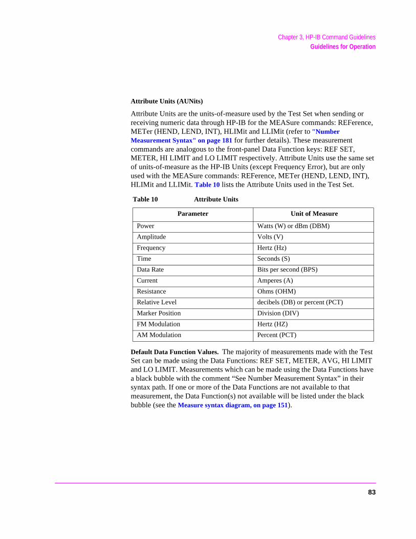
Chapter 3, HP-IB Command GuidelinesGuidelines for Operation
r
k
Attribute Units (AUNits)
Attribute Units are the units-of-measure used by the Test Set when sending or receiving numeric data through HP-IB for the MEASure commands: REFerence, METer (HEND, LEND, INT), HLIMit and LLIMit (refer to "Number Measurement Syntax" on page 181 for further details). These measurement commands are analogous to the front-panel Data Function keys: REF SET, METER, HI LIMIT and LO LIMIT respectively. Attribute Units use the same set of units-of-measure as the HP-IB Units (except Frequency Error), but are only used with the MEASure commands: REFerence, METer (HEND, LEND, INT), HLIMit and LLIMit. Table 10 lists the Attribute Units used in the Test Set.
Default Data Function Values. The majority of measurements made with the Test Set can be made using the Data Functions: REF SET, METER, AVG, HI LIMIT and LO LIMIT. Measurements which can be made using the Data Functions have a black bubble with the comment “See Number Measurement Syntax” in theisyntax path. If one or more of the Data Functions are not available to that measurement, the Data Function(s) not available will be listed under the blacbubble (see the Measure syntax diagram, on page 151).
Table 10 Attribute Units
Parameter Unit of Measure
Power Watts (W) or dBm (DBM)
Amplitude Volts (V)
Frequency Hertz (Hz)
Time Seconds (S)
Data Rate Bits per second (BPS)
Current Amperes (A)
Resistance Ohms (OHM)
Relative Level decibels (DB) or percent (PCT)
Marker Position Division (DIV)
FM Modulation Hertz (HZ)
AM Modulation Percent (PCT)
83
Chapter 3, HP-IB Command GuidelinesGuidelines for Operation
ows:
For each measurement that can be made using the Data Functions, there is a default set of values for each Data Function for that measurement.
For example, the Audio Frequency Analyzer Distortion measurement can be made using all of the Data Functions. This would include REF SET, METER, AVG, HI LIMIT and LO LIMIT. A complete listing of the Distortion measurement’s Data Functions and their default values would appear as foll
• The Attribute units are: PCT• The number of Averages is: 10• The Average state is: 0• The Reference value is: 1• The Reference Display units are: PCT• The Reference state is: 0• The High Limit is: 0• The High Limit Display units are: PCT• The High Limit state is: 0• The Low Limit is: 0• The Low Limit Display units are: PCT• The Low Limit state is: 0• The Meter state is: 0• The Meter high end setting is: 10• The Meter high end Display units are: PCT• The Meter low end setting is: 0• The Meter low end Display units are: PCT• The Meter interval is: 10
The Data Functions are set to their default values whenever
• the power is cycled on the Test Set• the front-panel PRESET key is selected• the *RST Common Command is received through HP-IB
84
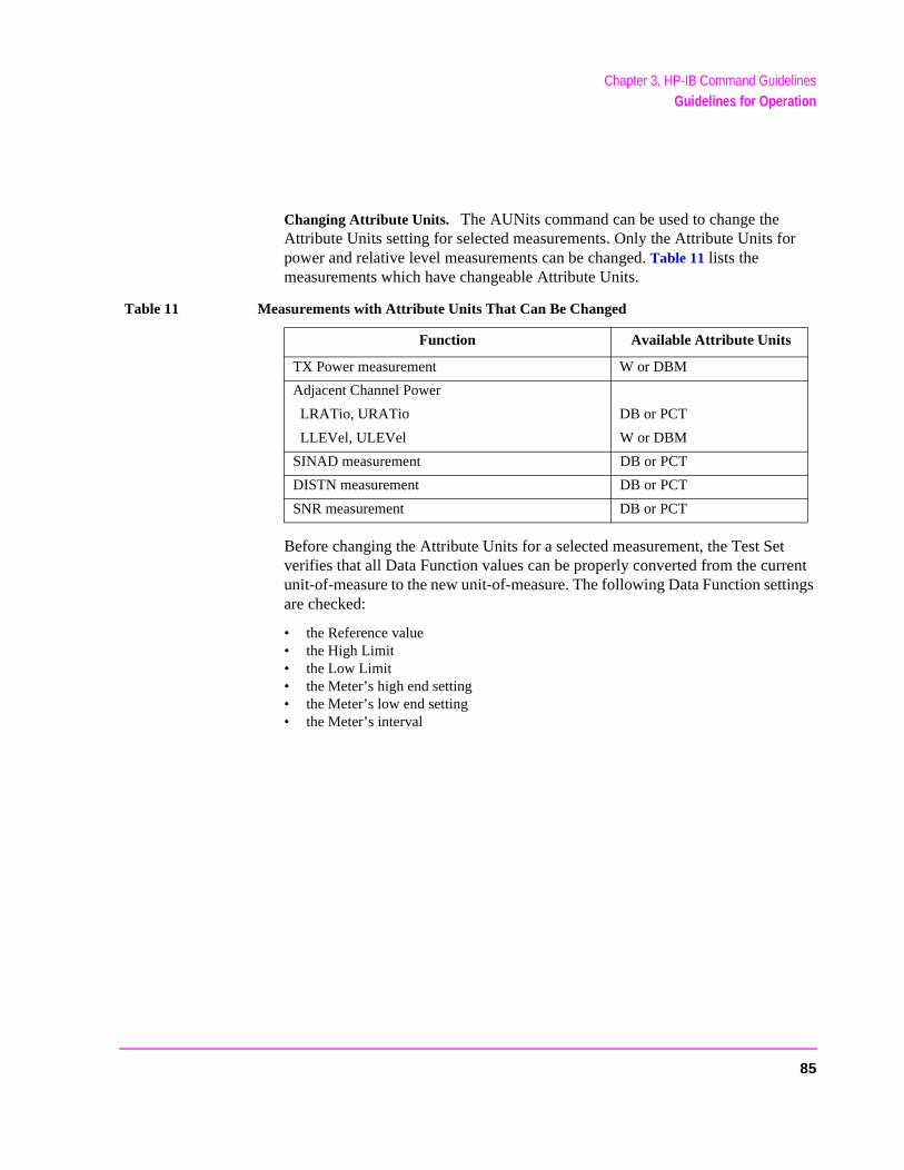
Chapter 3, HP-IB Command GuidelinesGuidelines for Operation
Changing Attribute Units. The AUNits command can be used to change the Attribute Units setting for selected measurements. Only the Attribute Units for power and relative level measurements can be changed. Table 11 lists the measurements which have changeable Attribute Units.
Before changing the Attribute Units for a selected measurement, the Test Set verifies that all Data Function values can be properly converted from the current unit-of-measure to the new unit-of-measure. The following Data Function settings are checked:
• the Reference value• the High Limit• the Low Limit• the Meter’s high end setting• the Meter’s low end setting• the Meter’s interval
Table 11 Measurements with Attribute Units That Can Be Changed
Function Available Attribute Units
TX Power measurement W or DBM
Adjacent Channel Power
LRATio, URATio DB or PCT
LLEVel, ULEVel W or DBM
SINAD measurement DB or PCT
DISTN measurement DB or PCT
SNR measurement DB or PCT
85
Chapter 3, HP-IB Command GuidelinesGuidelines for Operation
If it is not possible to properly convert all the values to the new unit-of-measure, the Attribute Units are not changed and the following error is generated: HP-IB Error: HP-IB Units cause invalid conversion of attr. This error is most often encountered when one of the Data Function values listed above is set to zero. If this error is encountered, the programmer must change the Data Function settings to values that can be converted to the new units-of-measure before sending the :AUNits command to the Test Set.
For example, the following BASIC language program statements
1. reset the Test Set2. set the Data Function default zero values to non-zero values 3. set the Attribute Units to DB4. then query the value of each Data Function
The units of measure for the returned values will be DB.
86
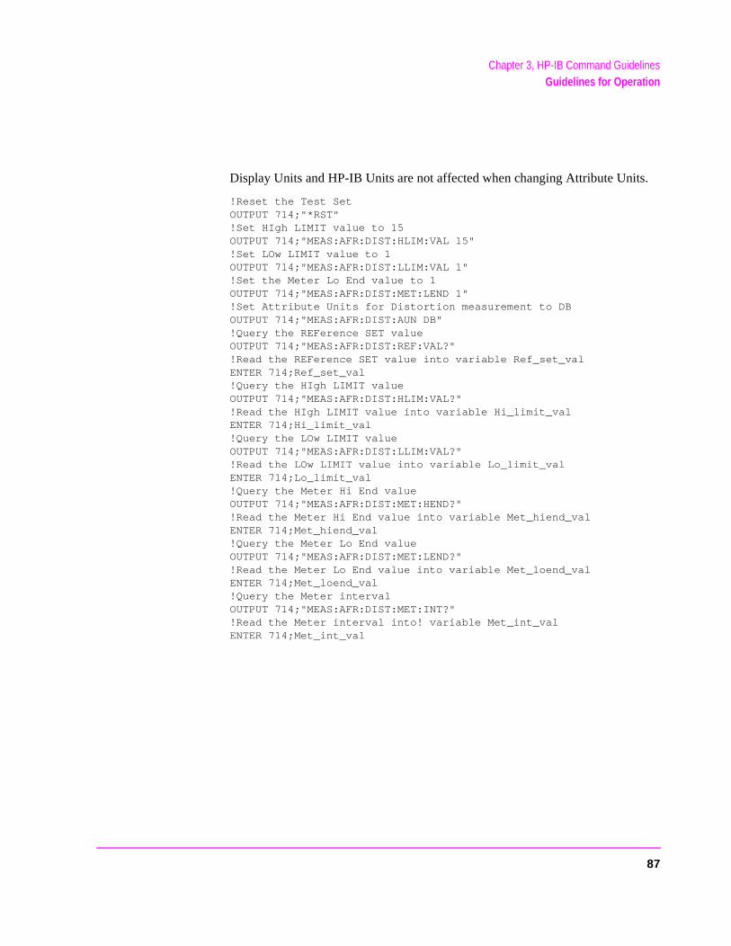
Chapter 3, HP-IB Command GuidelinesGuidelines for Operation
Display Units and HP-IB Units are not affected when changing Attribute Units.
!Reset the Test SetOUTPUT 714;"*RST"!Set HIgh LIMIT value to 15OUTPUT 714;"MEAS:AFR:DIST:HLIM:VAL 15"!Set LOw LIMIT value to 1OUTPUT 714;"MEAS:AFR:DIST:LLIM:VAL 1"!Set the Meter Lo End value to 1OUTPUT 714;"MEAS:AFR:DIST:MET:LEND 1"!Set Attribute Units for Distortion measurement to DBOUTPUT 714;"MEAS:AFR:DIST:AUN DB"!Query the REFerence SET valueOUTPUT 714;"MEAS:AFR:DIST:REF:VAL?"!Read the REFerence SET value into variable Ref_set_valENTER 714;Ref_set_val!Query the HIgh LIMIT valueOUTPUT 714;"MEAS:AFR:DIST:HLIM:VAL?"!Read the HIgh LIMIT value into variable Hi_limit_valENTER 714;Hi_limit_val!Query the LOw LIMIT valueOUTPUT 714;"MEAS:AFR:DIST:LLIM:VAL?"!Read the LOw LIMIT value into variable Lo_limit_valENTER 714;Lo_limit_val!Query the Meter Hi End valueOUTPUT 714;"MEAS:AFR:DIST:MET:HEND?"!Read the Meter Hi End value into variable Met_hiend_valENTER 714;Met_hiend_val!Query the Meter Lo End valueOUTPUT 714;"MEAS:AFR:DIST:MET:LEND?"!Read the Meter Lo End value into variable Met_loend_valENTER 714;Met_loend_val!Query the Meter intervalOUTPUT 714;"MEAS:AFR:DIST:MET:INT?"!Read the Meter interval into! variable Met_int_valENTER 714;Met_int_val
87
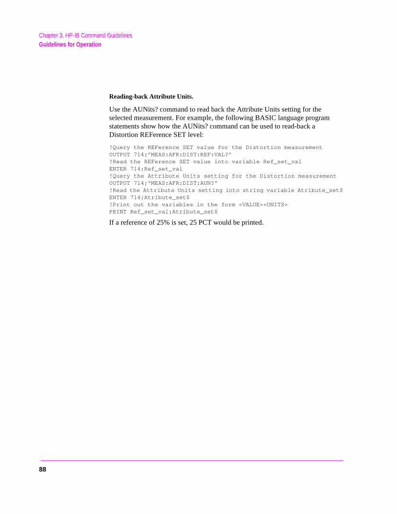
Chapter 3, HP-IB Command GuidelinesGuidelines for Operation
Reading-back Attribute Units.
Use the AUNits? command to read back the Attribute Units setting for the selected measurement. For example, the following BASIC language program statements show how the AUNits? command can be used to read-back a Distortion REFerence SET level:
!Query the REFerence SET value for the Distortion measurementOUTPUT 714;"MEAS:AFR:DIST:REF:VAL?"!Read the REFerence SET value into variable Ref_set_valENTER 714;Ref_set_val!Query the Attribute Units setting for the Distortion measurementOUTPUT 714;"MEAS:AFR:DIST:AUN?"!Read the Attribute Units setting into string variable Atribute_set$ENTER 714;Atribute_set$!Print out the variables in the form <VALUE><UNITS>PRINT Ref_set_val;Atribute_set$
If a reference of 25% is set, 25 PCT would be printed.
88
Chapter 3, HP-IB Command GuidelinesGuidelines for Operation
d he
e nt.
re
st
rifies
e
Guidelines for Attribute Units
• When setting the value of measurement functions REFerence, METer, HLIMit anLLIMit through HP-IB, a non–Attribute Unit unit-of-measure must be specified in tcommand string, otherwise the current Attribute Unit is assumed by the Test Set.
For example, if the Test Set is in a RESET condition and the command MEAS:AFR:DIST:REF:VAL 10 is sent through HP-IB, the Test Set will interpret thdata as 10 %, since % is the RESET Attribute Unit for the Distortion measuremeSending the command, MEAS:AFR:DIST:REF:VAL 10 DBM, would set the REFerence SET value to 10 dB.
• When querying measurement functions REFerence, METer, HLIMit and LLIMit through HP-IB, the Test Set always returns numeric values in Attribute Units, regardless of the current Display Units or HP-IB Units settings. Numeric values aexpressed in scientific notation.
For example, if the REF SET measurement function is displayed as 25% on the Te
Set, the value returned through HP-IB is +2.50000000E+001 (2.5×101). Converting the returned value to a format other than scientific notation must be done programmatically.
• Before changing the Attribute Units for a selected measurement, the Test Set vethat all Data Function values can be properly converted from the current unit-of-measure to the new unit-of-measure. If it is not possible to properly convert all thvalues to the new unit-of-measure, the Attribute Units are not changed and the following error is generated: HP-IB Error: HP-IB Units cause invalid conversion of attr.
89
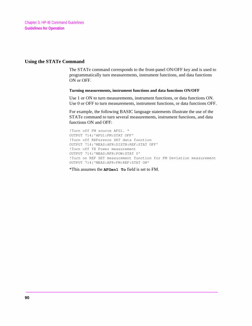
Chapter 3, HP-IB Command GuidelinesGuidelines for Operation
Using the STATe Command
The STATe command corresponds to the front-panel ON/OFF key and is used to programmatically turn measurements, instrument functions, and data functions ON or OFF.
Turning measurements, instrument functions and data functions ON/OFF
Use 1 or ON to turn measurements, instrument functions, or data functions ON. Use 0 or OFF to turn measurements, instrument functions, or data functions OFF.
For example, the following BASIC language statements illustrate the use of the STATe command to turn several measurements, instrument functions, and data functions ON and OFF:
!Turn off FM source AFG1. *OUTPUT 714;"AFG1:FM:STAT OFF"!Turn off REFerence SET data functionOUTPUT 714;"MEAS:AFR:DISTN:REF:STAT OFF"!Turn off TX Power measurementOUTPUT 714;"MEAS:RFR:POW:STAT 0"!Turn on REF SET measurement function for FM Deviation measurementOUTPUT 714;"MEAS:AFR:FM:REF:STAT ON"
*This assumes the AFGen1 To field is set to FM.
90
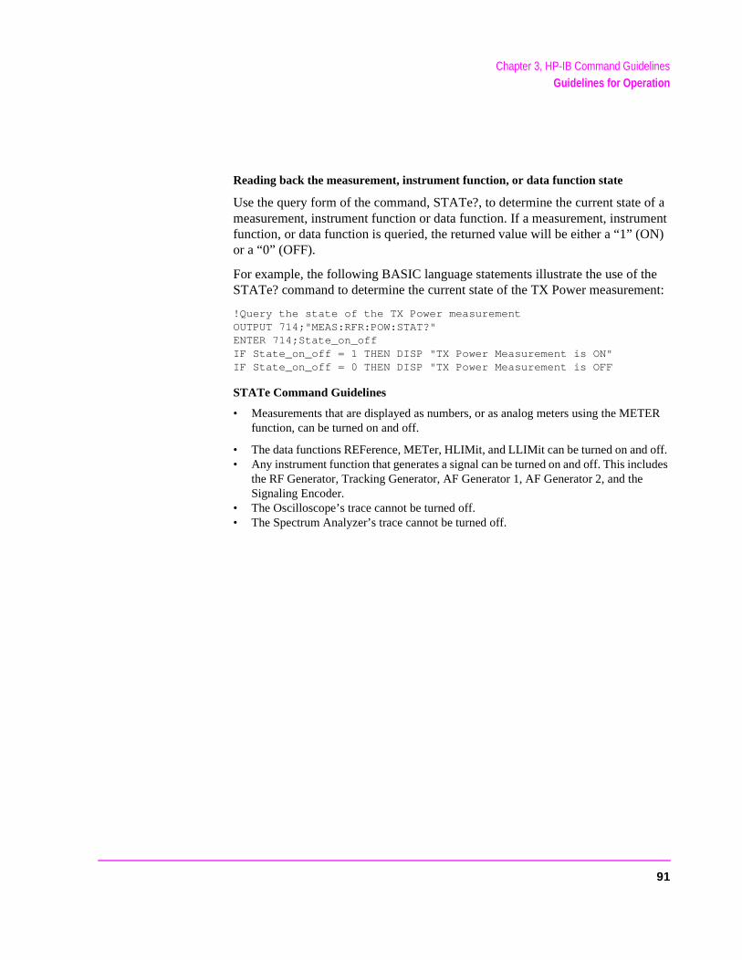
Chapter 3, HP-IB Command GuidelinesGuidelines for Operation
N)
he ent:
TER
off. ludes
Reading back the measurement, instrument function, or data function state
Use the query form of the command, STATe?, to determine the current state of a measurement, instrument function or data function. If a measurement, instrument function, or data function is queried, the returned value will be either a “1” (Oor a “0” (OFF).
For example, the following BASIC language statements illustrate the use of tSTATe? command to determine the current state of the TX Power measurem
!Query the state of the TX Power measurementOUTPUT 714;"MEAS:RFR:POW:STAT?"ENTER 714;State_on_offIF State_on_off = 1 THEN DISP "TX Power Measurement is ON"IF State_on_off = 0 THEN DISP "TX Power Measurement is OFF
STATe Command Guidelines
• Measurements that are displayed as numbers, or as analog meters using the MEfunction, can be turned on and off.
• The data functions REFerence, METer, HLIMit, and LLIMit can be turned on and • Any instrument function that generates a signal can be turned on and off. This inc
the RF Generator, Tracking Generator, AF Generator 1, AF Generator 2, and theSignaling Encoder.
• The Oscilloscope’s trace cannot be turned off. • The Spectrum Analyzer’s trace cannot be turned off.
91
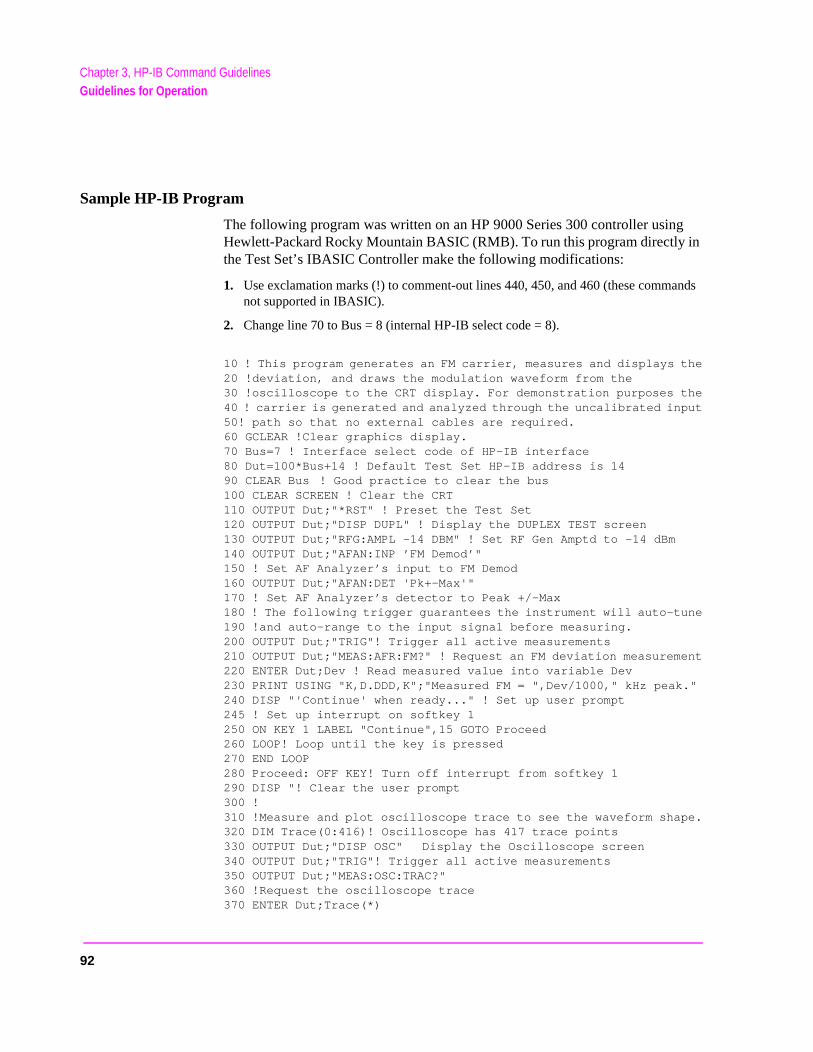
Chapter 3, HP-IB Command GuidelinesGuidelines for Operation
Sample HP-IB Program
The following program was written on an HP 9000 Series 300 controller using Hewlett-Packard Rocky Mountain BASIC (RMB). To run this program directly in the Test Set’s IBASIC Controller make the following modifications:
1. Use exclamation marks (!) to comment-out lines 440, 450, and 460 (these commands not supported in IBASIC).
2. Change line 70 to Bus = 8 (internal HP-IB select code = 8).
10 ! This program generates an FM carrier, measures and displays the20 !deviation, and draws the modulation waveform from the 30 !oscilloscope to the CRT display. For demonstration purposes the40 ! carrier is generated and analyzed through the uncalibrated input50! path so that no external cables are required.60 GCLEAR !Clear graphics display.70 Bus=7 ! Interface select code of HP-IB interface80 Dut=100*Bus+14 ! Default Test Set HP-IB address is 1490 CLEAR Bus ! Good practice to clear the bus100 CLEAR SCREEN ! Clear the CRT110 OUTPUT Dut;"*RST" ! Preset the Test Set120 OUTPUT Dut;"DISP DUPL" ! Display the DUPLEX TEST screen130 OUTPUT Dut;"RFG:AMPL -14 DBM" ! Set RF Gen Amptd to -14 dBm140 OUTPUT Dut;"AFAN:INP ’FM Demod’"150 ! Set AF Analyzer’s input to FM Demod160 OUTPUT Dut;"AFAN:DET 'Pk+-Max'"170 ! Set AF Analyzer’s detector to Peak +/-Max180 ! The following trigger guarantees the instrument will auto-tune190 !and auto-range to the input signal before measuring.200 OUTPUT Dut;"TRIG"! Trigger all active measurements210 OUTPUT Dut;"MEAS:AFR:FM?" ! Request an FM deviation measurement220 ENTER Dut;Dev ! Read measured value into variable Dev230 PRINT USING "K,D.DDD,K";"Measured FM = ",Dev/1000," kHz peak."240 DISP "'Continue' when ready..." ! Set up user prompt245 ! Set up interrupt on softkey 1250 ON KEY 1 LABEL "Continue",15 GOTO Proceed260 LOOP! Loop until the key is pressed270 END LOOP280 Proceed: OFF KEY! Turn off interrupt from softkey 1290 DISP "! Clear the user prompt300 !310 !Measure and plot oscilloscope trace to see the waveform shape.320 DIM Trace(0:416)! Oscilloscope has 417 trace points330 OUTPUT Dut;"DISP OSC" Display the Oscilloscope screen340 OUTPUT Dut;"TRIG"! Trigger all active measurements350 OUTPUT Dut;"MEAS:OSC:TRAC?" 360 !Request the oscilloscope trace370 ENTER Dut;Trace(*)
92
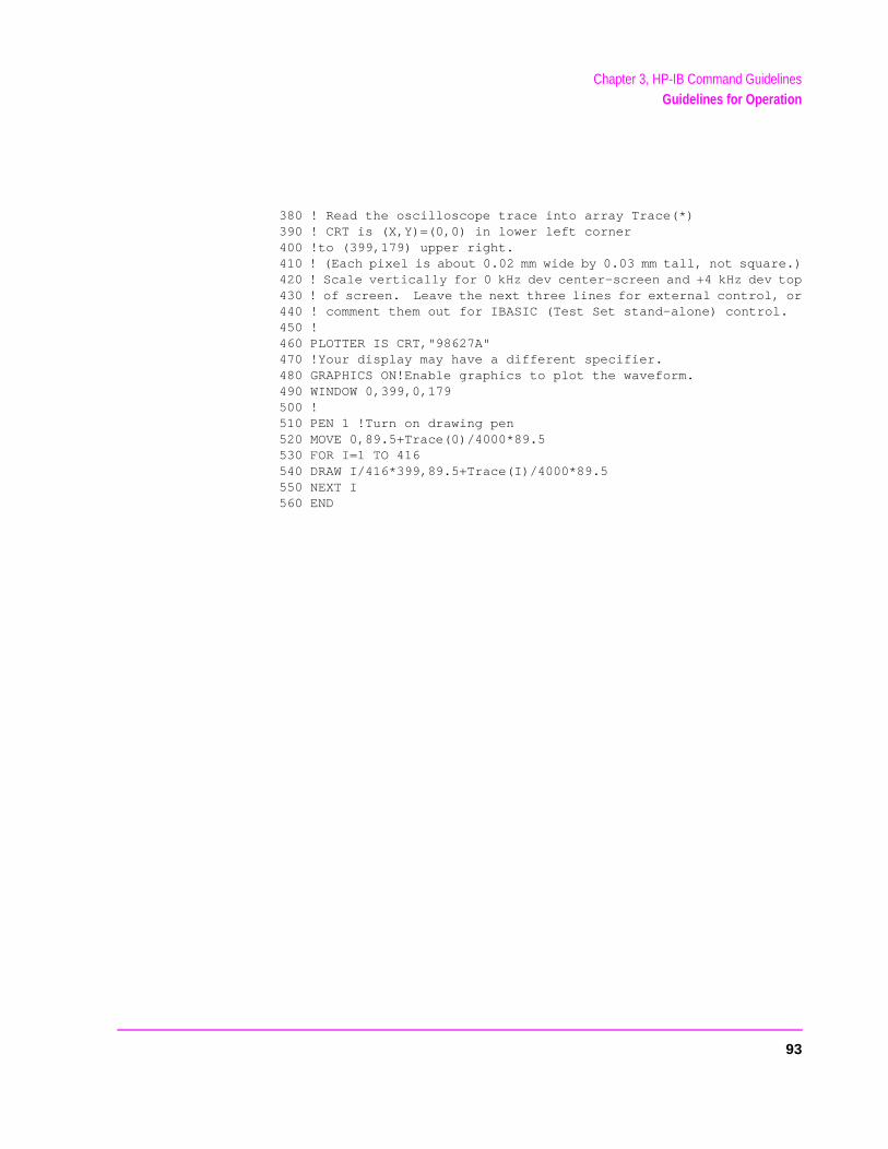
Chapter 3, HP-IB Command GuidelinesGuidelines for Operation
380 ! Read the oscilloscope trace into array Trace(*)390 ! CRT is (X,Y)=(0,0) in lower left corner 400 !to (399,179) upper right.410 ! (Each pixel is about 0.02 mm wide by 0.03 mm tall, not square.)420 ! Scale vertically for 0 kHz dev center-screen and +4 kHz dev top430 ! of screen. Leave the next three lines for external control, or440 ! comment them out for IBASIC (Test Set stand-alone) control.450 !460 PLOTTER IS CRT,"98627A" 470 !Your display may have a different specifier.480 GRAPHICS ON!Enable graphics to plot the waveform.490 WINDOW 0,399,0,179500 !510 PEN 1 !Turn on drawing pen520 MOVE 0,89.5+Trace(0)/4000*89.5530 FOR I=1 TO 416540 DRAW I/416*399,89.5+Trace(I)/4000*89.5550 NEXT I560 END
93

Chapter 3, HP-IB Command GuidelinesGuidelines for Operation
94
4
HP-IB Commands
95
Chapter 4, HP-IB CommandsHP-IB Syntax Diagrams
HP-IB Syntax Diagrams
HP-IB Command Syntax Diagram Listing
Instrument Command Syntax Diagrams
AF Analyzer (AFAN), page 101.AF Generator 1 (AFG1), page 104.AF Generator 2 (AFG2) - Pre-Modulation Filters, page 105.AF Generator 2 and Encoder (AFG2, ENC), page 106.
AFG2:AMPS, page 107.AFG2:CDCSs, page 111.AFG2:DPAGing, page 112.AFG2:DTMF, page 111.AFG2:EDACs, page 118.AFG2:FGENerator, page 114.AFG2:LTR, page 117.AFG2:MPT1327, page 119.AFG2:NAMPs, page 109.AFG2:NMT, page 115.AFG2:NTACs, page 109.AFG2:TACS, page 107.AFG2:TSEQuential, page 114.
Adjacent Channel Power (ACP), page 99.Call Process(CALLP), page 126.Decoder (DEC), page 145.
DEC:AMPS, page 147.DEC:CDCSs, page 147.DEC:DPAGing, page 147.DEC:DTMF, page 147.DEC:EDACs, page 146.DEC:FGENerator, page 147.DEC:LTR, page 148.DEC:MPT1327, page 148.DEC:NAMPs, page 146.DEC:NTACs, page 146.DEC:TACS, page 147.DEC:TSEQuential, page 148.
Oscilloscope (OSC), page 158.RF Analyzer (RFA), page 165.RF Generator (RFG), page 167.Radio Interface (RINT), page 168.Spectrum Analyzer (SAN), page 169.
96
Chapter 4, HP-IB CommandsHP-IB Syntax Diagrams
Instrument Command Number Setting Syntax Diagrams
Integer Number Setting Syntax, page 178.Real Number Setting Syntax, page 179.Multiple Real Number Setting Syntax, page 180.
Measurement Command Syntax Diagrams
Measure (MEAS), page 151.Trigger (TRIG), page 177.
Measurement Command Number Setting Syntax Diagrams
Number Measurement Syntax, page 181.Multiple Number Measurement Syntax, page 183.
Instrument Function Syntax Diagrams
Configure and I/O Configure (CONF), page 121.Display (DISP), page 149.Program (PROG), page 163.Save/Recall Registers (REG), page 164.Status (STAT), page 172.System (SYS), page 173.Tests (TEST), page 174.
HP-IB Only Command Syntax Diagram
Special (SPEC), page 171.
97
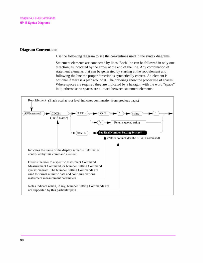
Chapter 4, HP-IB CommandsHP-IB Syntax Diagrams
pace”
Diagram Conventions
Use the following diagram to see the conventions used in the syntax diagrams.
Statement elements are connected by lines. Each line can be followed in only one direction, as indicated by the arrow at the end of the line. Any combination of statement elements that can be generated by starting at the root element and following the line the proper direction is syntactically correct. An element is optional if there is a path around it. The drawings show the proper use of spaces. Where spaces are required they are indicated by a hexagon with the word “sin it, otherwise no spaces are allowed between statement elements.
string
Returns quoted string
(Field Name)
(*Does not included the :STATe command)
:CDCSs :CODE space
:RATE See Real Number Setting Syntax*
‘ ‘
?
AFGenerator2
Root Element
Indicates the name of the display screen’s field that iscontrolled by this command element.
Directs the user to a specific Instrument Command,Measurement Command, or Number Setting Commandsyntax diagram. The Number Setting Commands areused to format numeric data and configure variousinstrument measurement parameters.
Notes indicate which, if any, Number Setting Commands arenot supported by this particular path.
(Black oval at root level indicates continuation from previous page.)
98
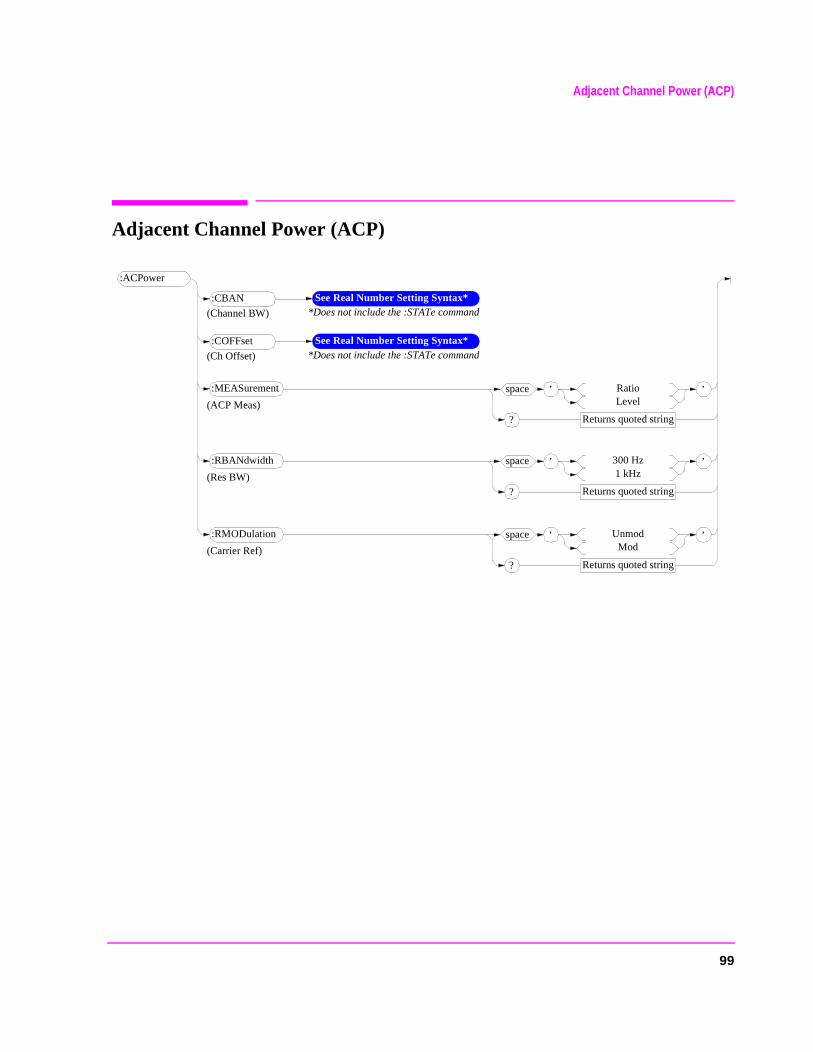
Adjacent Channel Power (ACP)
Adjacent Channel Power (ACP)
:ACPower
’space RatioLevel
Returns quoted string?
’:MEASurement
:CBAN See Real Number Setting Syntax**Does not include the :STATe command(Channel BW)
:COFFset See Real Number Setting Syntax**Does not include the :STATe command(Ch Offset)
(ACP Meas)
’space 300 Hz1 kHz
Returns quoted string?
’:RBANdwidth
(Res BW)
’space UnmodMod
Returns quoted string?
’:RMODulation
(Carrier Ref)
99

Adjacent Channel Power (ACP)
100
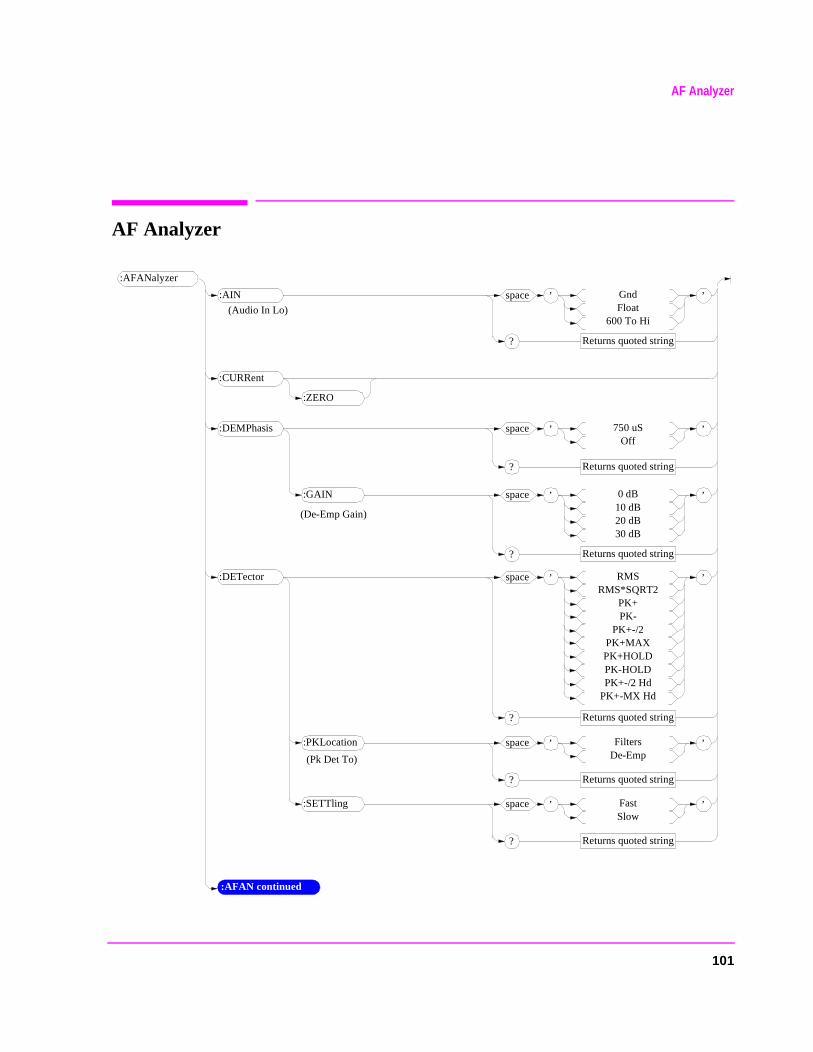
AF Analyzer
AF Analyzer
’space GndFloat
600 To Hi
Returns quoted string?
’
:AFANalyzer
:AIN
’space 0 dB10 dB20 dB30 dB
Returns quoted string?
’
:CURRent
’space 750 uSOff
Returns quoted string?
’:DEMPhasis
(Audio In Lo)
:AFAN continued
:ZERO
:GAIN
’space RMSRMS*SQRT2
PK+PK-
PK+-/2PK+MAXPK+HOLDPK-HOLDPK+-/2 Hd
PK+-MX Hd
Returns quoted string?
’:DETector
’space FiltersDe-Emp
Returns quoted string?
’:PKLocation
’space FastSlow
Returns quoted string?
’:SETTling
(De-Emp Gain)
(Pk Det To)
101
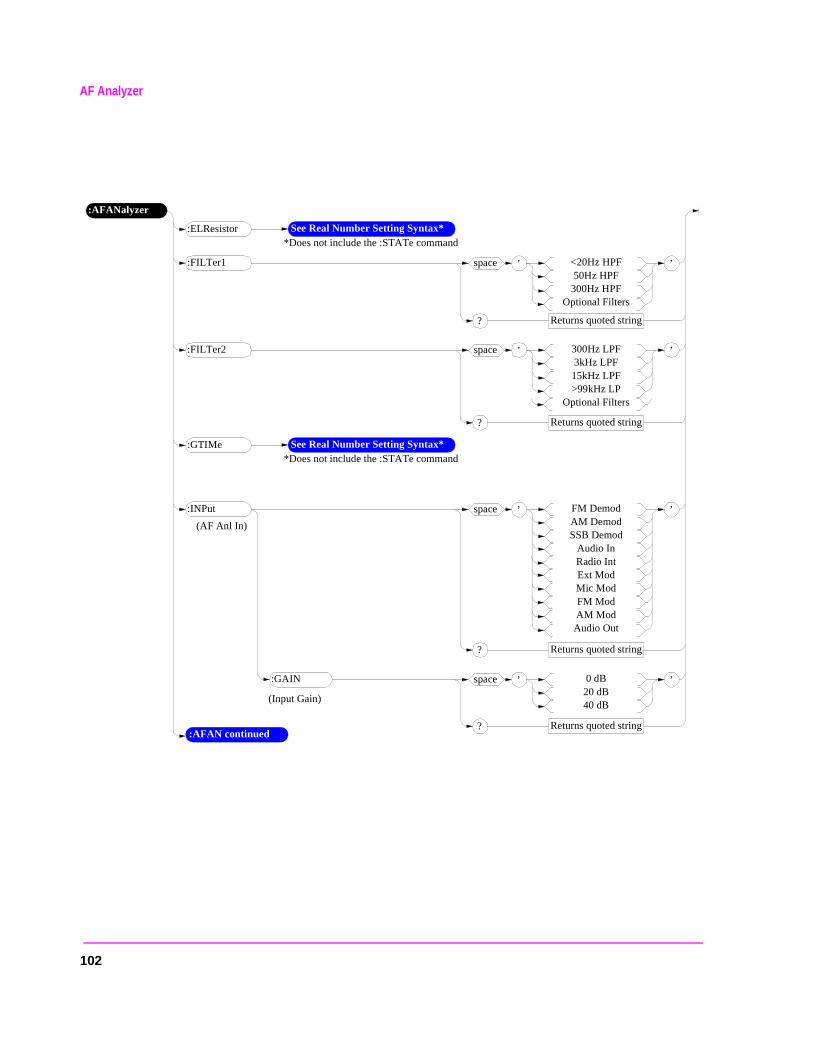
AF Analyzer
’space <20Hz HPF50Hz HPF
300Hz HPFOptional Filters
Returns quoted string?
’
:AFANalyzer
:FILTer1
’space 0 dB20 dB40 dB
Returns quoted string?
’
:AFAN continued
:GAIN
’space FM DemodAM DemodSSB Demod
Audio InRadio IntExt ModMic ModFM ModAM ModAudio Out
Returns quoted string?
’:INPut
(AF Anl In)
(Input Gain)
:ELResistor See Real Number Setting Syntax**Does not include the :STATe command
’space 300Hz LPF3kHz LPF15kHz LPF>99kHz LP
Optional Filters
Returns quoted string?
’:FILTer2
:GTIMe See Real Number Setting Syntax**Does not include the :STATe command
102
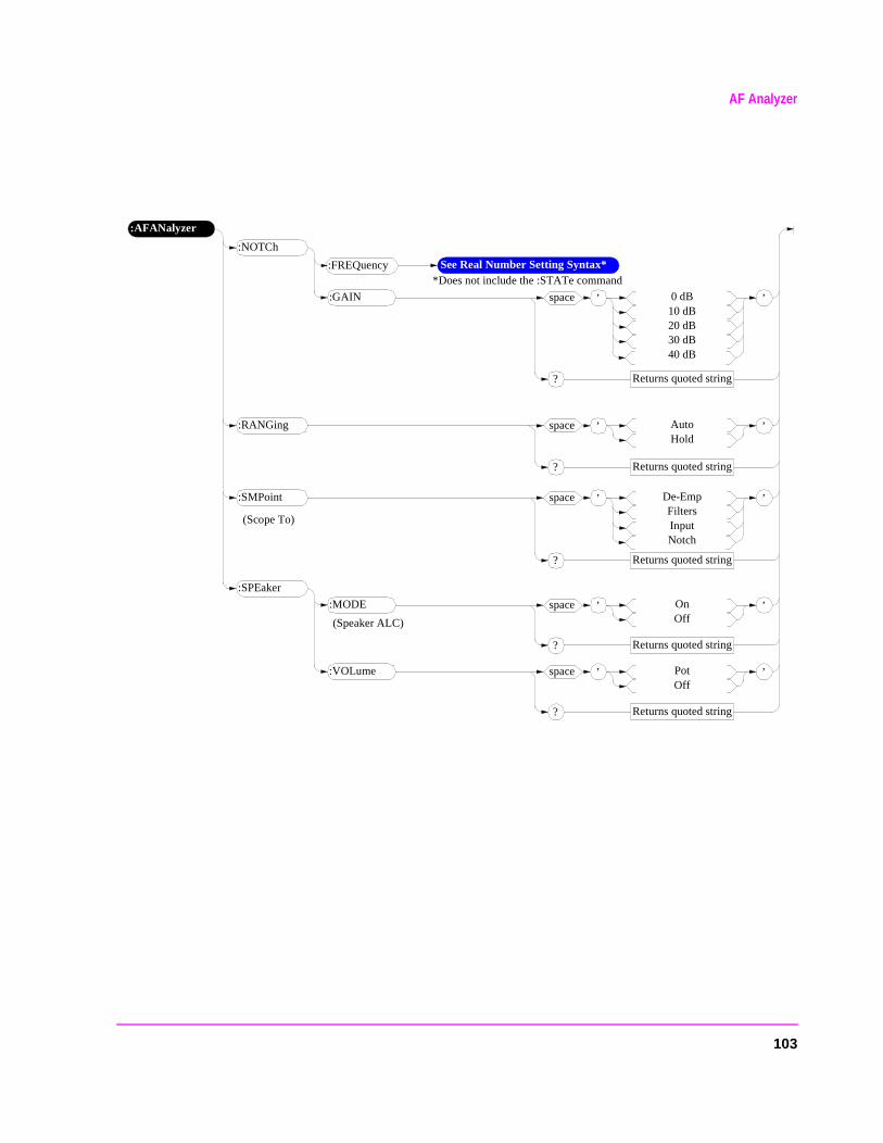
AF Analyzer
:AFANalyzer
:NOTCh
:FREQuency See Real Number Setting Syntax**Does not include the :STATe command
’space 0 dB10 dB20 dB30 dB40 dB
Returns quoted string?
’:GAIN
’space AutoHold
Returns quoted string?
’:RANGing
’space De-EmpFiltersInputNotch
Returns quoted string?
’:SMPoint
(Scope To)
:SPEaker
’space OnOff
Returns quoted string?
’:MODE
’space PotOff
Returns quoted string?
’:VOLume
(Speaker ALC)
103
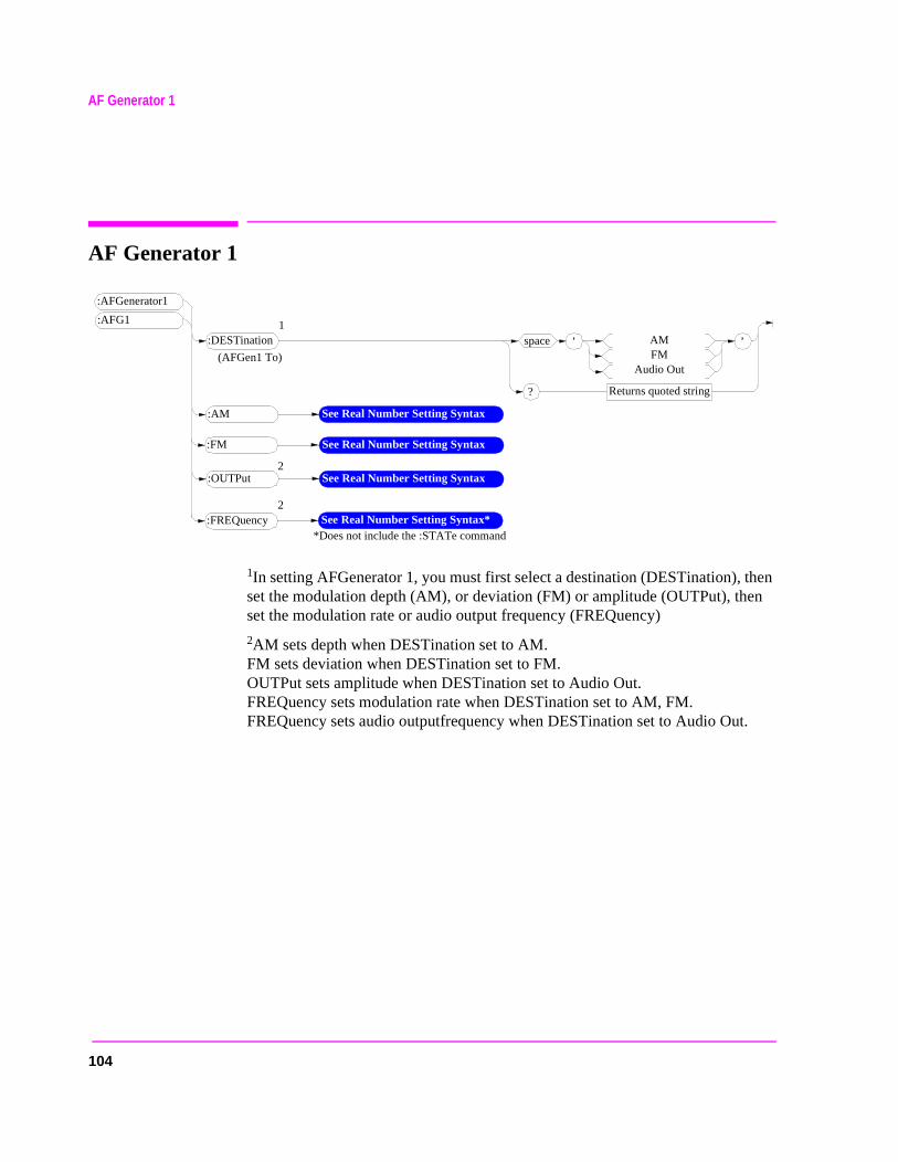
104
AF Generator 1
AF Generator 1
1In setting AFGenerator 1, you must first select a destination (DESTination), then set the modulation depth (AM), or deviation (FM) or amplitude (OUTPut), then set the modulation rate or audio output frequency (FREQuency)
2AM sets depth when DESTination set to AM. FM sets deviation when DESTination set to FM. OUTPut sets amplitude when DESTination set to Audio Out. FREQuency sets modulation rate when DESTination set to AM, FM.FREQuency sets audio outputfrequency when DESTination set to Audio Out.
’space AMFM
Audio Out
Returns quoted string?
’
:AFGenerator1
:DESTination
(AFGen1 To)
:AM See Real Number Setting Syntax
:FREQuency See Real Number Setting Syntax**Does not include the :STATe command
:FM
:OUTPut
1
2
2
See Real Number Setting Syntax
See Real Number Setting Syntax
:AFG1
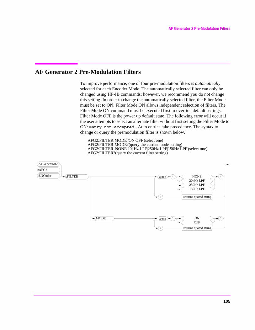
105
AF Generator 2 Pre-Modulation Filters
AF Generator 2 Pre-Modulation Filters
To improve performance, one of four pre-modulation filters is automatically selected for each Encoder Mode. The automatically selected filter can only be changed using HP-IB commands; however, we recommend you do not change this setting. In order to change the automatically selected filter, the Filter Mode must be set to ON. Filter Mode ON allows independent selection of filters. The Filter Mode ON command must be executed first to override default settings. Filter Mode OFF is the power up default state. The following error will occur if the user attempts to select an alternate filter without first setting the Filter Mode to ON: Entry not accepted. Auto entries take precedence. The syntax to change or query the premodulation filter is shown below.
AFG2:FILTER:MODE ’ON|OFF’(select one)AFG2:FILTER:MODE?(query the current mode setting)AFG2:FILTER ’NONE|20kHz LPF|250Hz LPF|150Hz LPF’(select one)AFG2:FILTER?(query the current filter setting)
’space NONE20kHz LPF250Hz LPF150Hz LPF
Returns quoted string?
’
:AFGenerator2
:FILTER
’space ONOFF
Returns quoted string?
’:MODE
:ENCoder
:AFG2
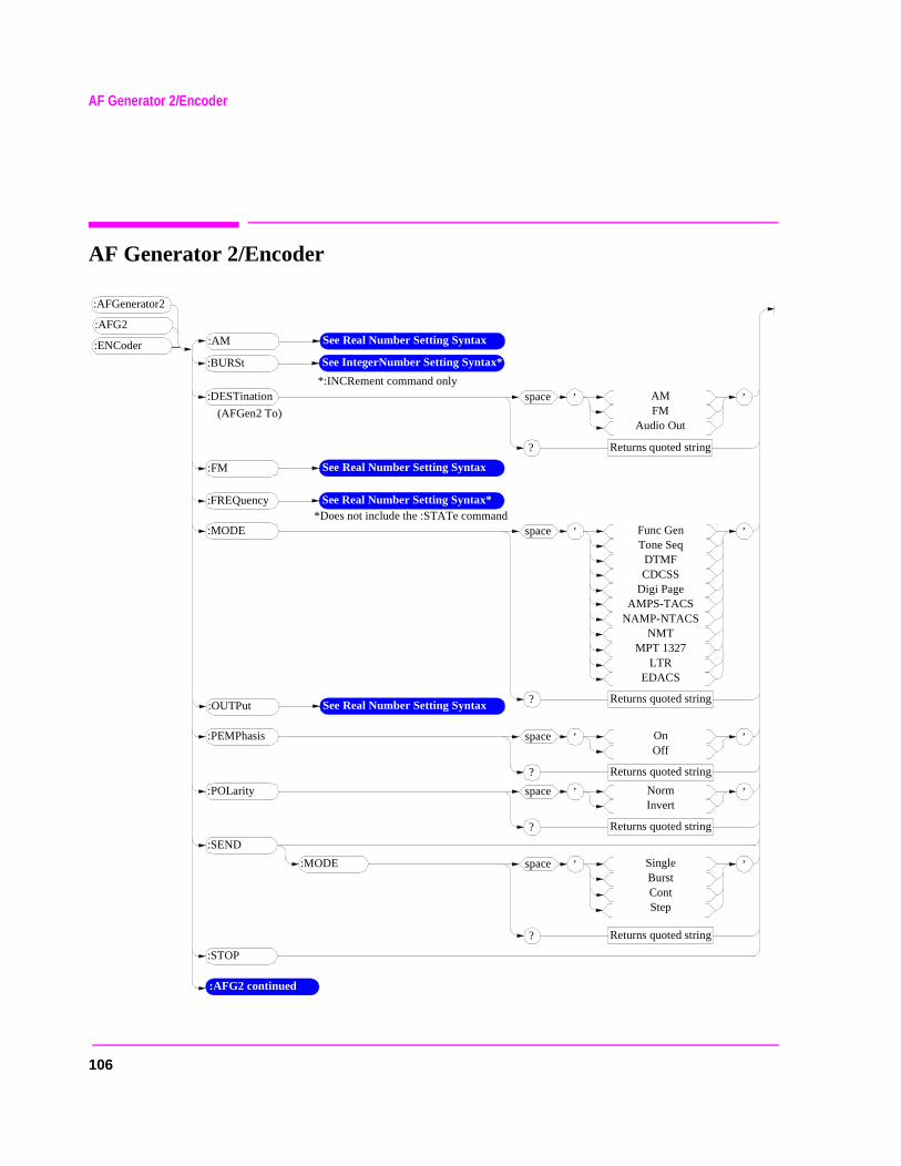
AF Generator 2/Encoder
AF Generator 2/Encoder
’space SingleBurstContStep
Returns quoted string?
’
:SEND
:MODE
’space AMFM
Audio Out
Returns quoted string?
’:DESTination
(AFGen2 To)
:AM See Real Number Setting Syntax
:FREQuency See Real Number Setting Syntax**Does not include the :STATe command
:BURSt See IntegerNumber Setting Syntax*
*:INCRement command only
:FM See Real Number Setting Syntax
’space Func GenTone Seq
DTMFCDCSS
Digi PageAMPS-TACS
NAMP-NTACSNMT
MPT 1327LTR
EDACS
Returns quoted string?
’:MODE
:STOP
’space OnOff
Returns quoted string?
’:PEMPhasis
’space NormInvert
Returns quoted string?
’:POLarity
:AFG2 continued
:OUTPut See Real Number Setting Syntax
:AFGenerator2
:ENCoder
:AFG2
106
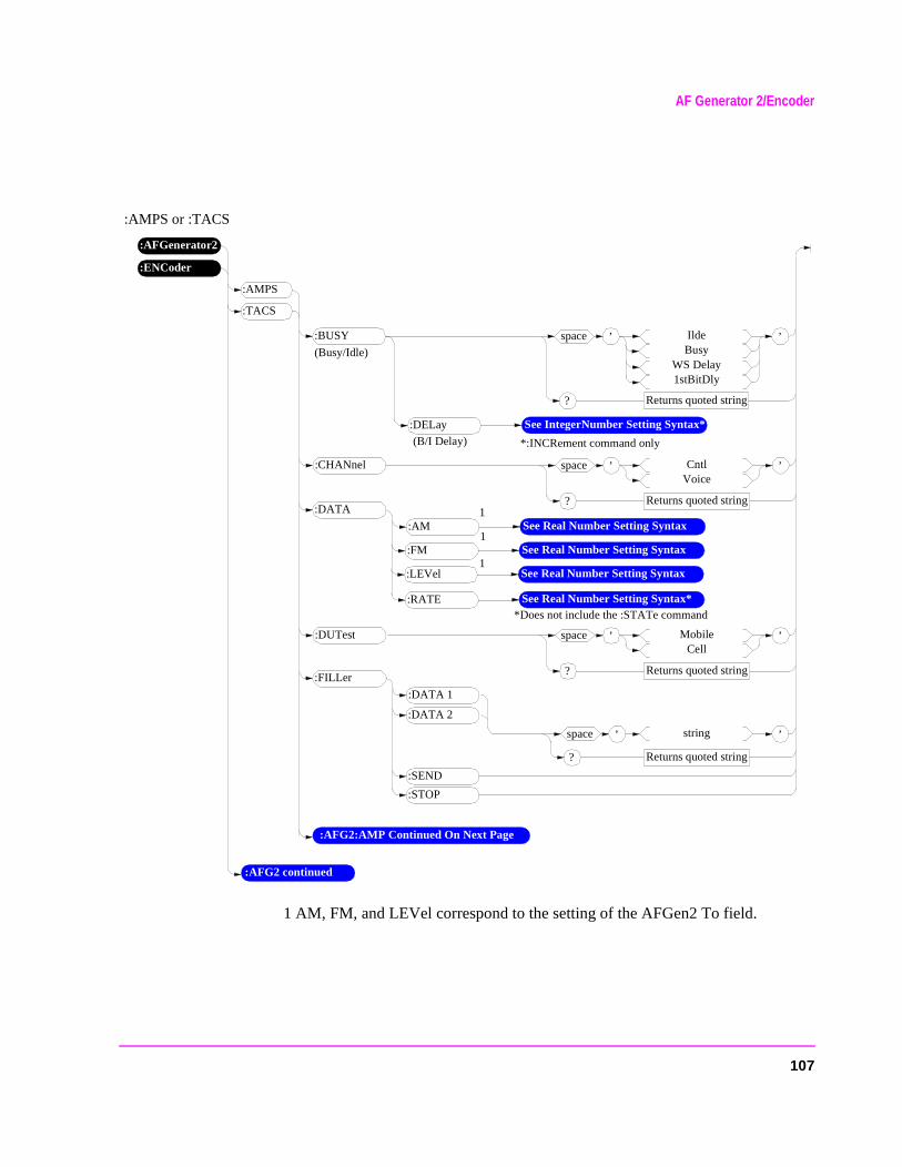
AF Generator 2/Encoder
:AMPS or :TACS
1 AM, FM, and LEVel correspond to the setting of the AFGen2 To field.
’space IldeBusy
WS Delay1stBitDly
Returns quoted string?
’:BUSY
(Busy/Idle)
:AM See Real Number Setting Syntax
’space CntlVoice
Returns quoted string?
’:CHANnel
’space MobileCell
Returns quoted string?
’:DUTest
:AMPS
:TACS
:DELay See IntegerNumber Setting Syntax*
*:INCRement command only(B/I Delay)
:FM See Real Number Setting Syntax
:LEVel See Real Number Setting Syntax
:RATE See Real Number Setting Syntax**Does not include the :STATe command
:DATA
1
1
1
:DATA 1
:FILLer
:DATA 2
:STOP
:SEND
’space string
Returns quoted string?
’
:AFGenerator2
:ENCoder
:AFG2 continued
:AFG2:AMP Continued On Next Page
107
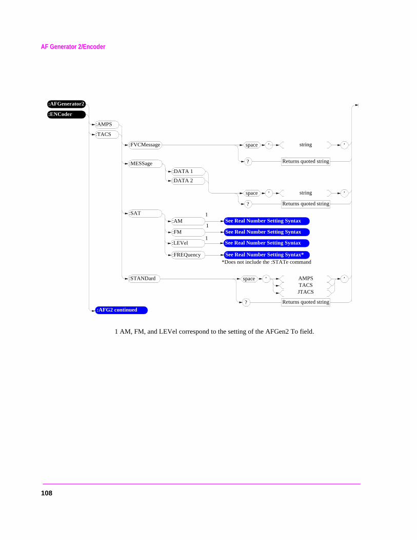
AF Generator 2/Encoder
1 AM, FM, and LEVel correspond to the setting of the AFGen2 To field.
’space AMPSTACSJTACS
Returns quoted string?
’:STANDard
:AFG2 continued
:FVCMessage ’space string
Returns quoted string?
’
:DATA 1
:MESSage
:DATA 2
’space string
Returns quoted string?
’
:AM See Real Number Setting Syntax
:FM See Real Number Setting Syntax
:LEVel See Real Number Setting Syntax
:FREQuency See Real Number Setting Syntax**Does not include the :STATe command
:SAT
1
1
1
:AMPS
:TACS
:AFGenerator2
:ENCoder
108
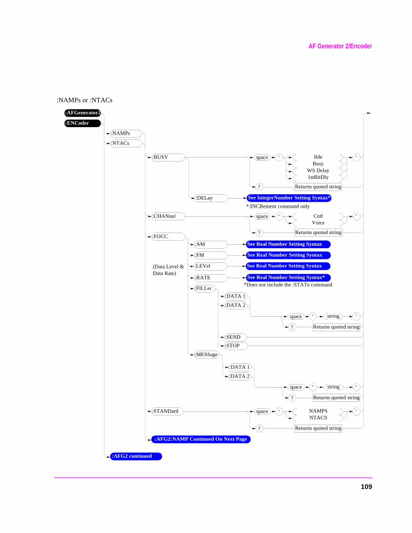
AF Generator 2/Encoder
:NAMPs or :NTACs
’space NAMPSNTACS
Returns quoted string?
’
:AFGenerator2
:STANDard
:ENCoder
’space IldeBusy
WS Delay1stBitDly
Returns quoted string?
’:BUSY
:AM See Real Number Setting Syntax
’space CntlVoice
Returns quoted string?
’:CHANnel
:AFG2 continued
:NAMPs
:NTACs
:DELay See IntegerNumber Setting Syntax*
*:INCRement command only
:FM See Real Number Setting Syntax
:LEVel See Real Number Setting Syntax
:RATE See Real Number Setting Syntax**Does not include the :STATe command
:FOCC
:DATA 1
:FILLer
:DATA 2
:STOP
:SEND
:MESSage
’space string
Returns quoted string?
’
’space string
Returns quoted string?
’
(Data Level & Data Rate)
:AFG2:NAMP Continued On Next Page
:DATA 1
:DATA 2
109
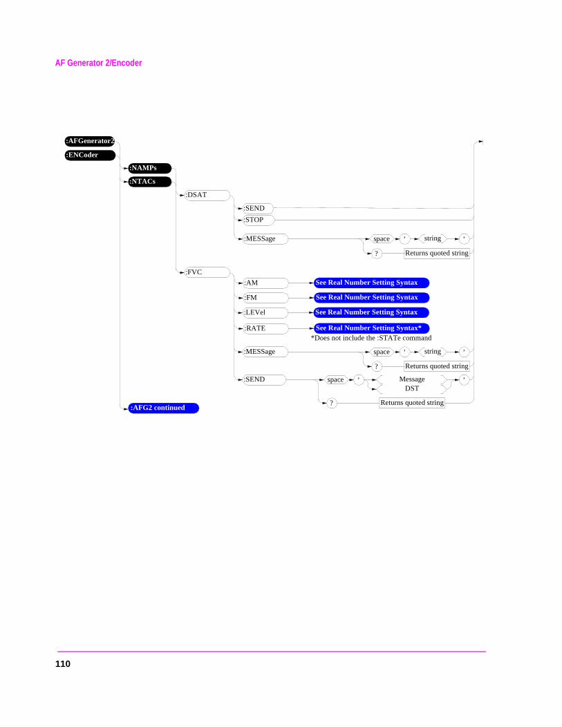
AF Generator 2/Encoder
:AFGenerator2
:ENCoder
:AFG2 continued
:NAMPs
:NTACs
:DSAT
:STOP
:SEND
:MESSage ’space string
Returns quoted string?
’
:AM See Real Number Setting Syntax
:FM See Real Number Setting Syntax
:LEVel See Real Number Setting Syntax
:RATE See Real Number Setting Syntax**Does not include the :STATe command
:FVC
:MESSage ’space string
Returns quoted string?
’
’space MessageDST
Returns quoted string?
’:SEND
110
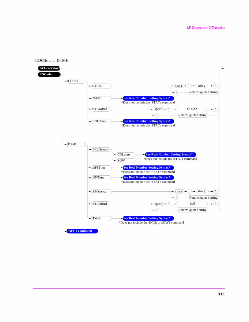
AF Generator 2/Encoder
:CDCSs and :DTMF
:AFGenerator2
:ENCoder
:AFG2 continued
:CDCSs
:CODE ’space string
Returns quoted string?
’
:RATE See Real Number Setting Syntax**Does not include the :STATe command
’space CDCSS
Returns quoted string?
’:STANdard
:TOCTime See Real Number Setting Syntax**Does not include the :STATe command
:DTMF
:SEQuence ’space string
Returns quoted string?
’
See Real Number Setting Syntax**Does not include the :STATe command
’space Bell
Returns quoted string?
’:STANdard
:OFFTime See Real Number Setting Syntax**Does not include the :STATe command
:ONTime See Real Number Setting Syntax**Does not include the :STATe command
:TWISt See Real Number Setting Syntax**Does not include the :INCR or :STAT command
:COLumn
:ROW
:FREQuency
111
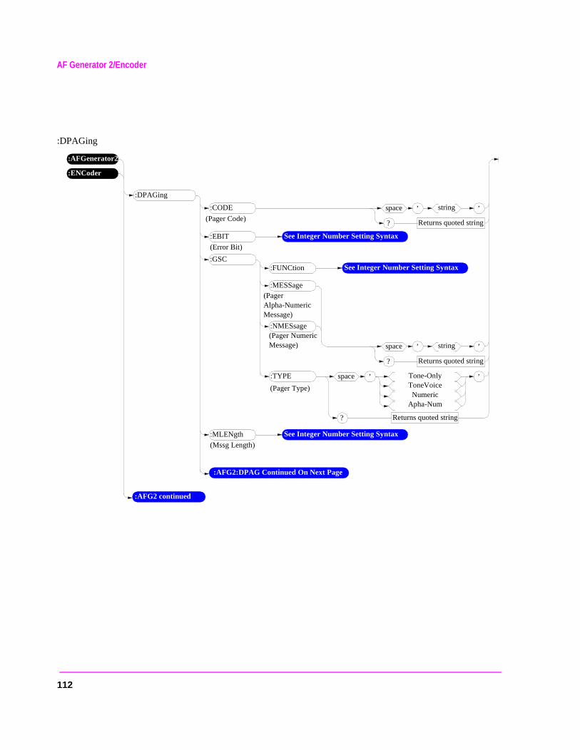
AF Generator 2/Encoder
:DPAGing
:AFGenerator2
:ENCoder
:DPAGing
:GSC
:CODE ’space string
Returns quoted string?
’
:EBIT See Integer Number Setting Syntax
(Error Bit)
:FUNCtion See Integer Number Setting Syntax
’space Tone-OnlyToneVoiceNumeric
Apha-Num
Returns quoted string?
’:TYPE
:MLENgth See Integer Number Setting Syntax
(Mssg Length)
(Pager Type)
(Pager Code)
:AFG2 continued
:AFG2:DPAG Continued On Next Page
:MESSage
’space string
Returns quoted string?
’
(Pager Numeric Message)
:NMESsage
(PagerAlpha-Numeric Message)
112
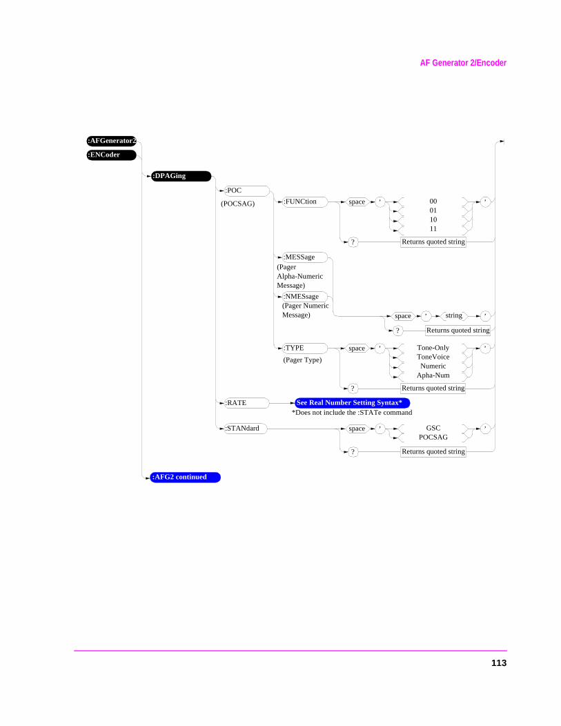
AF Generator 2/Encoder
’space GSCPOCSAG
Returns quoted string?
’
:AFGenerator2
:STANdard
:ENCoder
:AFG2 continued
:DPAGing
:RATE See Real Number Setting Syntax**Does not include the :STATe command
:POC
:MESSage
’space string
Returns quoted string?
’
(Pager Numeric Message)
:NMESsage
(PagerAlpha-Numeric Message)
’space Tone-OnlyToneVoiceNumeric
Apha-Num
Returns quoted string?
’:TYPE
(Pager Type)
’space 00011011
Returns quoted string?
’:FUNCtion(POCSAG)
113
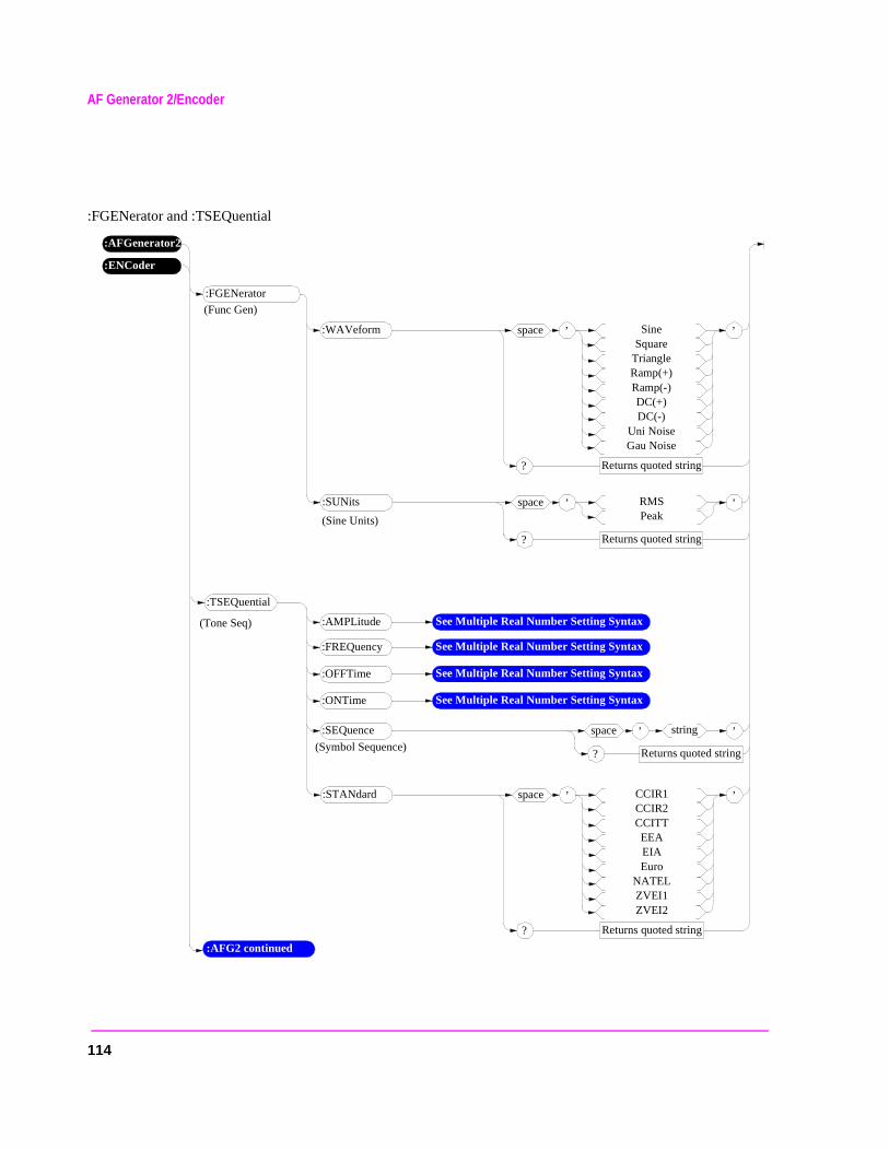
AF Generator 2/Encoder
:FGENerator and :TSEQuential
:AFGenerator2
:ENCoder
:AFG2 continued
:FGENerator
:SEQuence ’space string
Returns quoted string?
’
:AMPLitude See Multiple Real Number Setting Syntax
’space RMSPeak
Returns quoted string?
’:SUNits
(Sine Units)
:TSEQuential
(Tone Seq)
(Symbol Sequence)
(Func Gen)
’space SineSquare
TriangleRamp(+)Ramp(-)DC(+)DC(-)
Uni NoiseGau Noise
Returns quoted string?
’:WAVeform
:FREQuency See Multiple Real Number Setting Syntax
:OFFTime See Multiple Real Number Setting Syntax
:ONTime See Multiple Real Number Setting Syntax
’space CCIR1CCIR2CCITTEEAEIAEuro
NATELZVEI1ZVEI2
Returns quoted string?
’:STANdard
114
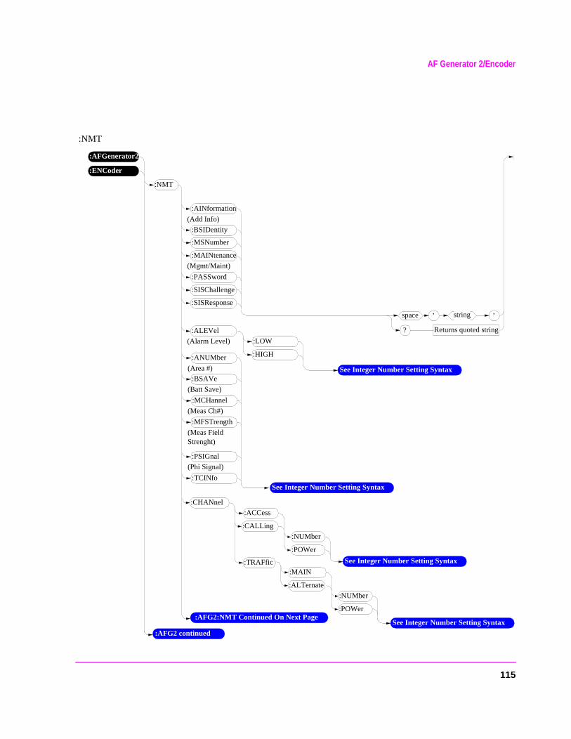
AF Generator 2/Encoder
:NMT
:AFGenerator2
:ENCoder
:NMT
:AINformation
’space string
Returns quoted string?
’
(Add Info)
:BSIDentity
:MSNumber
:MAINtenance
:PASSword
:SISChallenge
:SISResponse
(Mgmt/Maint)
(Alarm Level)
:ALEVel
:HIGH
:LOW
See Integer Number Setting Syntax
:ANUMber
(Area #)
:BSAVe
:MCHannel
:MFSTrength
:PSIGnal
:TCINfo
(Meas Field Strenght)
See Integer Number Setting Syntax
(Batt Save)
(Meas Ch#)
(Phi Signal)
:CHANnel
:CALLing
:ACCess
See Integer Number Setting Syntax:TRAFfic
:POWer
:NUMber
:ALTernate
:MAIN
:POWer
:NUMber
:AFG2 continued
:AFG2:NMT Continued On Next PageSee Integer Number Setting Syntax
115
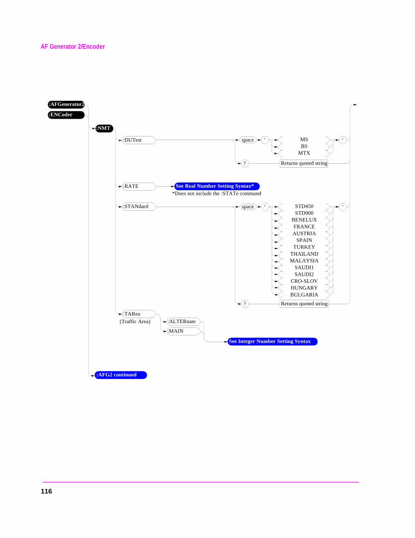
AF Generator 2/Encoder
:AFGenerator2
:ENCoder
:NMT
’space MSBS
MTX
Returns quoted string?
’:DUTest
(Traffic Area)
:TARea
:MAIN
:ALTERnate
See Integer Number Setting Syntax
’space STD450STD900
BENELUXFRANCEAUSTRIA
SPAINTURKEY
THAILANDMALAYSIA
SAUDI1SAUDI2
CRO-SLOVHUNGARYBULGARIA
Returns quoted string?
’:STANdard
:RATE See Real Number Setting Syntax**Does not include the :STATe command
:AFG2 continued
116
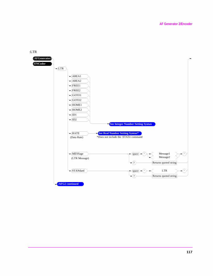
AF Generator 2/Encoder
:LTR
:AFGenerator2
:ENCoder
:LTR
:AREA1
:AREA2
:FREE1
:FREE2
:GOTO1
:GOTO2
:HOME1
See Integer Number Setting Syntax
:HOME2
:ID1
:ID2
:AFG2 continued
:RATE See Real Number Setting Syntax**Does not include the :STATe command
’space Message1Message2
Returns quoted string?
’:MESSage
(LTR Message)
(Data Rate)
’space LTR
Returns quoted string?
’:STANdard
117
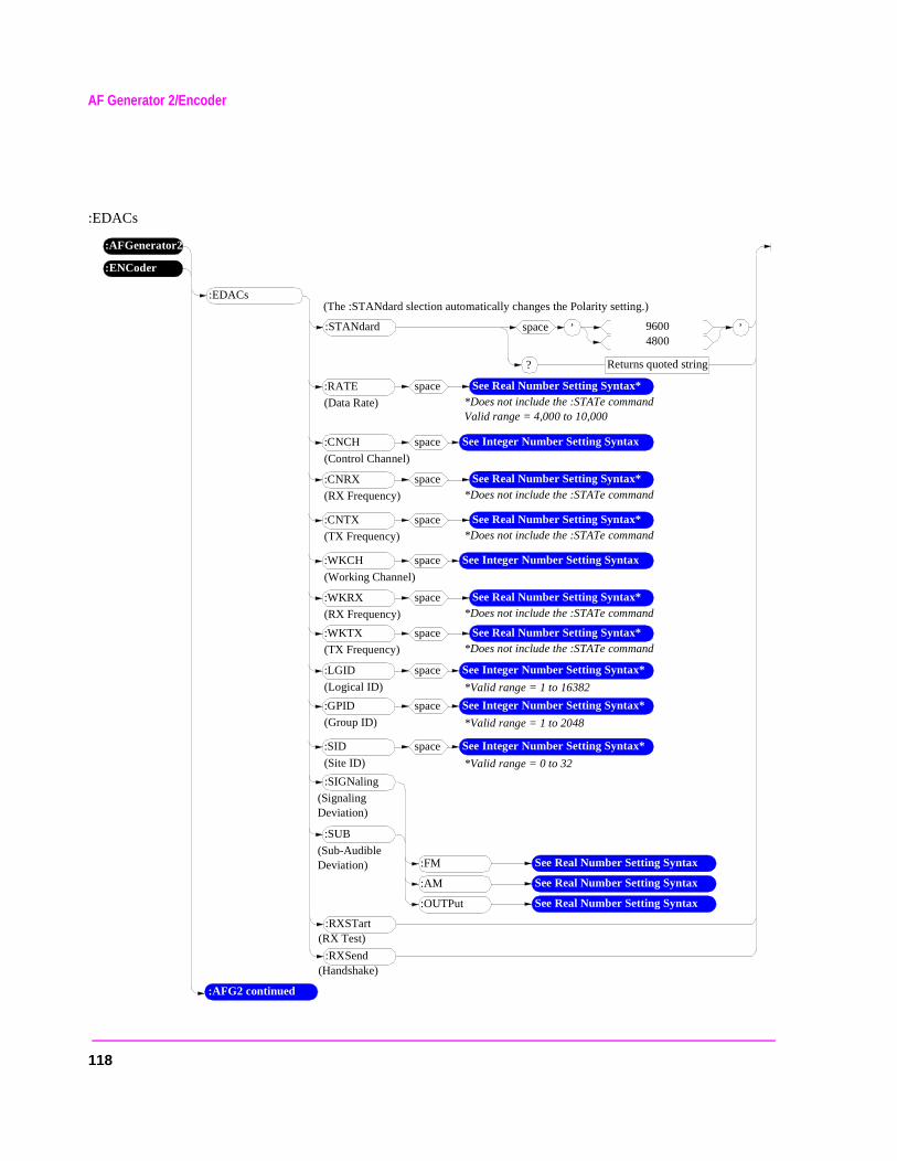
AF Generator 2/Encoder
:EDACs
:AFGenerator2
:ENCoder
:AFG2 continued
:EDACs
:CNCH See Integer Number Setting Syntax
(Control Channel)
’space 96004800
Returns quoted string?
’:STANdard
(Data Rate)
:RATE See Real Number Setting Syntax**Does not include the :STATe commandValid range = 4,000 to 10,000
space
space
(RX Frequency)
:CNRX See Real Number Setting Syntax**Does not include the :STATe command
space
(TX Frequency)
:CNTX See Real Number Setting Syntax**Does not include the :STATe command
space
:WKCH See Integer Number Setting Syntax
(Working Channel)
space
(RX Frequency)
:WKRX See Real Number Setting Syntax**Does not include the :STATe command
space
(TX Frequency)
:WKTX See Real Number Setting Syntax**Does not include the :STATe command
space
*Valid range = 1 to 16382
:LGID See Integer Number Setting Syntax*
(Logical ID)
space
*Valid range = 1 to 2048
:GPID See Integer Number Setting Syntax*
(Group ID)
space
*Valid range = 0 to 32
:SID See Integer Number Setting Syntax*
(Site ID)
space
(Signaling Deviation)
:SIGNaling
:AM See Real Number Setting Syntax
:FM See Real Number Setting Syntax
:OUTPut See Real Number Setting Syntax
(Sub-Audible Deviation)
:SUB
:RXSTart(RX Test)
:RXSend(Handshake)
(The :STANdard slection automatically changes the Polarity setting.)
118
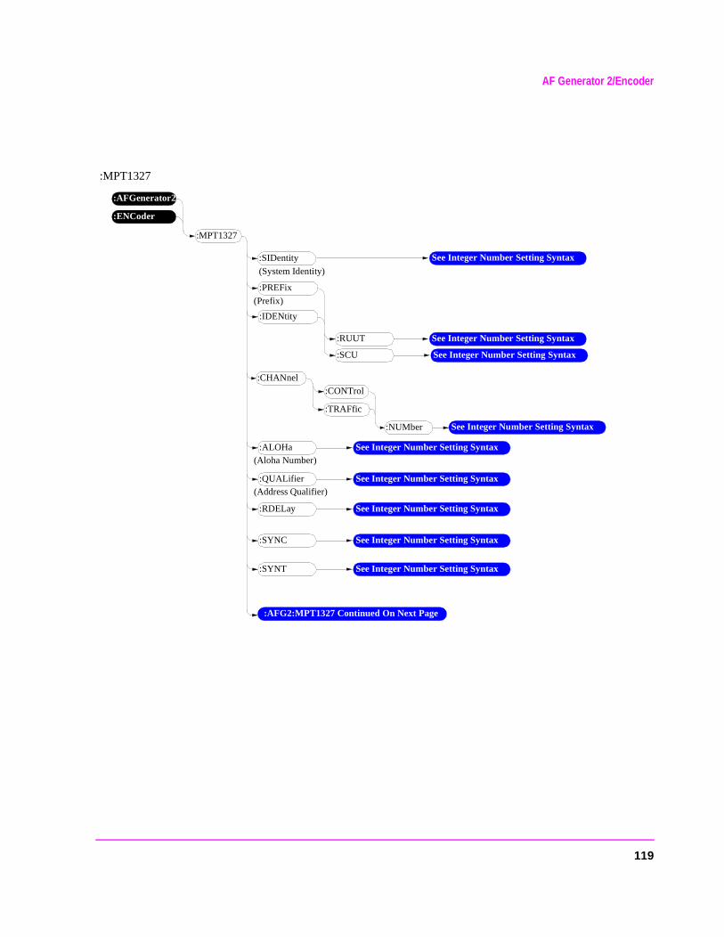
AF Generator 2/Encoder
:MPT1327
:AFGenerator2
:ENCoder
:MPT1327
:SIDentity
(System Identity)
(Prefix)
:PREFix
:SCU
:RUUT See Integer Number Setting Syntax
See Integer Number Setting Syntax
(Aloha Number)
:IDENtity
See Integer Number Setting Syntax
:CHANnel
:CONTrol
See Integer Number Setting Syntax
:TRAFfic
:NUMber
:ALOHa See Integer Number Setting Syntax
(Address Qualifier):QUALifier See Integer Number Setting Syntax
:RDELay See Integer Number Setting Syntax
:SYNC See Integer Number Setting Syntax
:SYNT See Integer Number Setting Syntax
:AFG2:MPT1327 Continued On Next Page
119
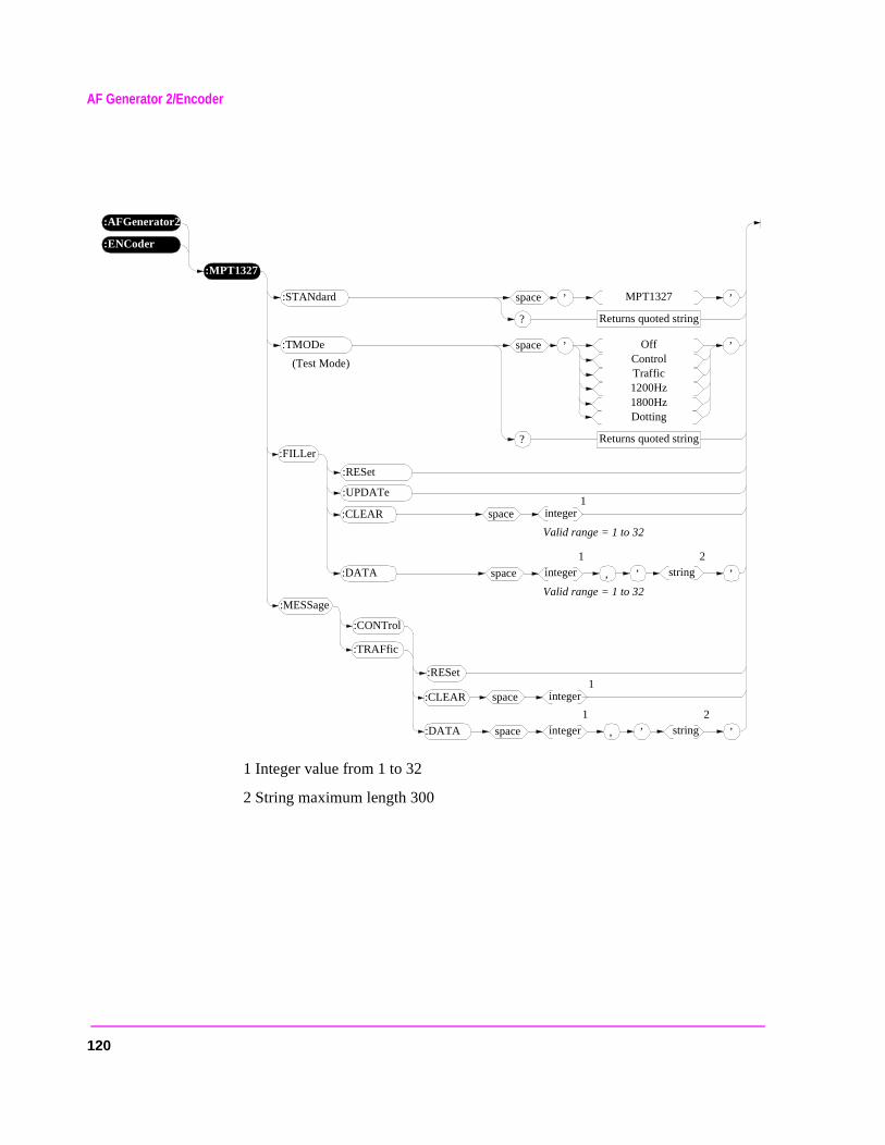
AF Generator 2/Encoder
1 Integer value from 1 to 32
2 String maximum length 300
:AFGenerator2
:ENCoder
:MPT1327
’space MPT1327
Returns quoted string?
’:STANdard
’space OffControlTraffic1200Hz1800HzDotting
Returns quoted string?
’:TMODe
(Test Mode)
,space integer
:FILLer
:CLEAR
:DATA
:RESet
:UPDATe
space integer
’ string ’
1 2
1
,space integer
:MESSage
:CLEAR
:DATA
:RESet
space integer
’ string ’
1 2
1
:TRAFfic
:CONTrol
Valid range = 1 to 32
Valid range = 1 to 32
120
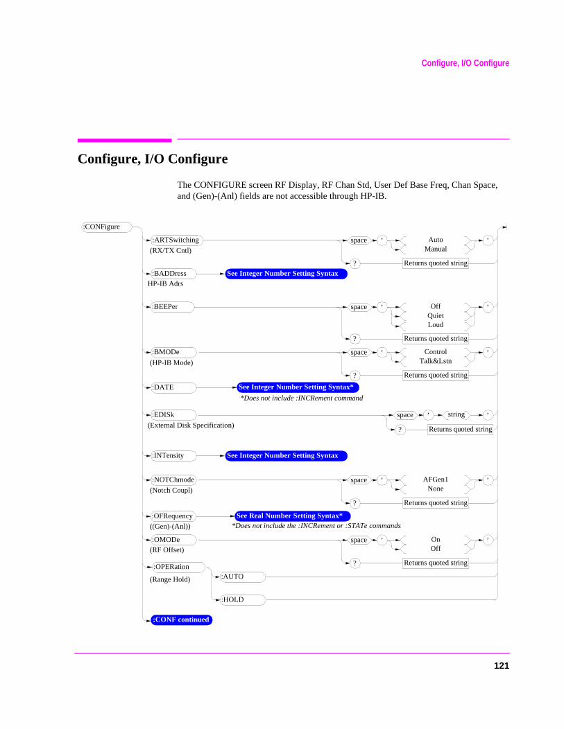
Configure, I/O Configure
Configure, I/O Configure
The CONFIGURE screen RF Display, RF Chan Std, User Def Base Freq, Chan Space, and (Gen)-(Anl) fields are not accessible through HP-IB.
:CONFigure
:CONF continued
:AUTO:OPERation
’space AutoManual
Returns quoted string?
’:ARTSwitching
(Range Hold)
:HOLD
’space OnOff
Returns quoted string?
’:OMODe
(RX/TX Cntl)
(RF Offset)
See Real Number Setting Syntax**Does not include the :INCRement or :STATe commands
:OFRequency
((Gen)-(Anl))
’space AFGen1None
Returns quoted string?
’:NOTChmode
(Notch Coupl)
:INTensity See Integer Number Setting Syntax
’space OffQuietLoud
Returns quoted string?
’:BEEPer
HP-IB Adrs:BADDress See Integer Number Setting Syntax
’space ControlTalk&Lstn
Returns quoted string?
’:BMODe
(HP-IB Mode)
*Does not include :INCRement command
:DATE See Integer Number Setting Syntax*
:EDISk ’space string
Returns quoted string?
’(External Disk Specification)
121
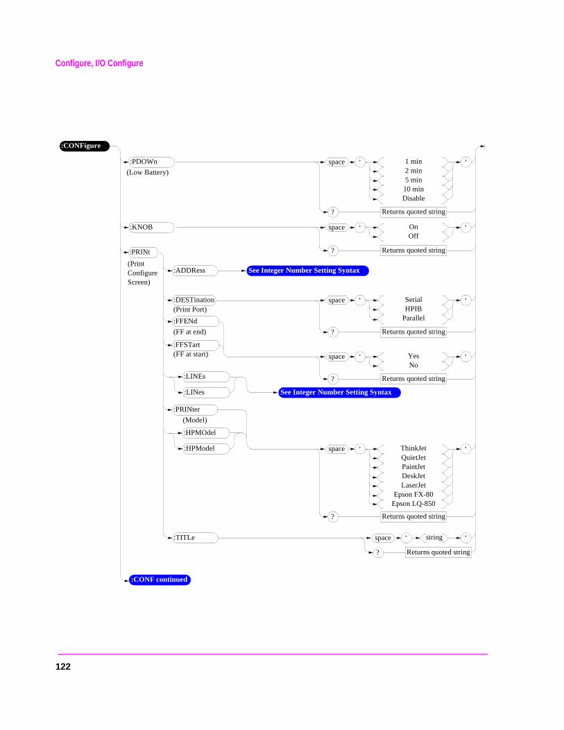
Configure, I/O Configure
:CONFigure
’space OnOff
Returns quoted string?
’:KNOB
’space 1 min2 min5 min
10 minDisable
Returns quoted string?
’:PDOWn
(Low Battery)
’space YesNo
Returns quoted string?
’
:FFENd
(Print Configure Screen)
:ADDRess See Integer Number Setting Syntax
’space SerialHPIB
Parallel
Returns quoted string?
’:DESTination
:FFSTart
(FF at end)
(Print Port)
(FF at start)
:LINEs
:LINes See Integer Number Setting Syntax
’space ThinkJetQuietJetPaintJetDeskJetLaserJet
Epson FX-80Epson LQ-850
Returns quoted string?
’
:PRINter
(Model)
:HPMOdel
:HPModel
:TITLe ’space string
Returns quoted string?
’
:CONF continued
122
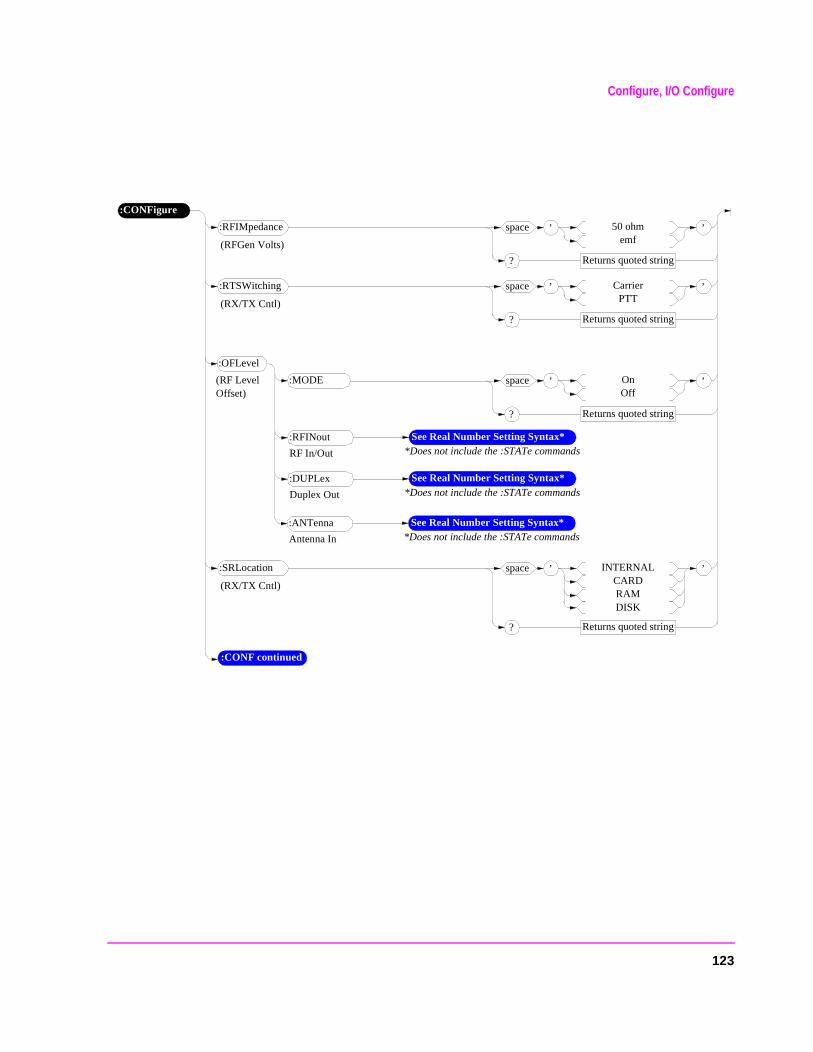
Configure, I/O Configure
:CONFigure
:OFLevel
(RF Level Offset)
(RFGen Volts)
’space OnOff
Returns quoted string?
’:MODE
:CONF continued
See Real Number Setting Syntax**Does not include the :STATe commands
:RFINout
RF In/Out
See Real Number Setting Syntax**Does not include the :STATe commands
:DUPLex
Duplex Out
See Real Number Setting Syntax**Does not include the :STATe commands
:ANTenna
Antenna In
’space 50 ohmemf
Returns quoted string?
’:RFIMpedance
(RX/TX Cntl)
’space CarrierPTT
Returns quoted string?
’:RTSWitching
(RX/TX Cntl)
’space INTERNALCARDRAMDISK
Returns quoted string?
’:SRLocation
123
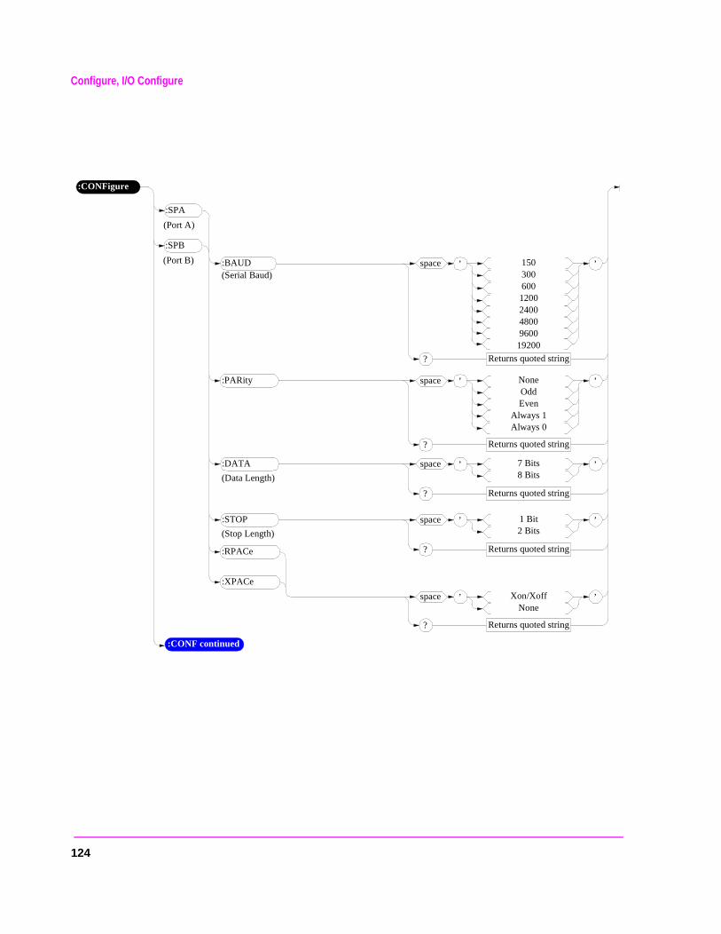
Configure, I/O Configure
:CONFigure
:SPB
(Port B) ’space 1503006001200240048009600
19200
Returns quoted string?
’:BAUD(Serial Baud)
:CONF continued
’space NoneOddEven
Always 1Always 0
Returns quoted string?
’:PARity
’space 7 Bits8 Bits
Returns quoted string?
’:DATA
(Data Length)
’space 1 Bit2 Bits
Returns quoted string?
’:STOP
(Stop Length)
’space Xon/XoffNone
Returns quoted string?
’
:RPACe
:XPACe
:SPA
(Port A)
124
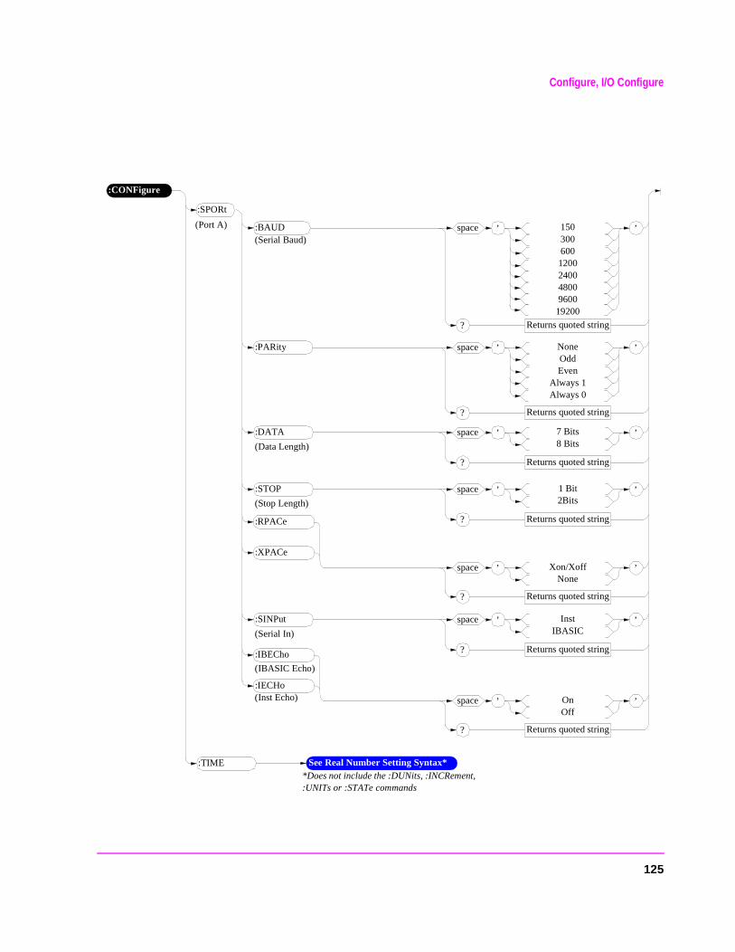
Configure, I/O Configure
:CONFigure
’space OnOff
Returns quoted string?
’
:IBECho
:SPORt
(Port A) ’space 1503006001200240048009600
19200
Returns quoted string?
’:BAUD
:IECHo
(IBASIC Echo)
(Serial Baud)
(Inst Echo)
’space NoneOddEven
Always 1Always 0
Returns quoted string?
’:PARity
’space 7 Bits8 Bits
Returns quoted string?
’:DATA
(Data Length)
’space 1 Bit2Bits
Returns quoted string?
’:STOP
(Stop Length)
’space Xon/XoffNone
Returns quoted string?
’
:RPACe
:XPACe
’space InstIBASIC
Returns quoted string?
’:SINPut
(Serial In)
See Real Number Setting Syntax**Does not include the :DUNits, :INCRement, :UNITs or :STATe commands
:TIME
125
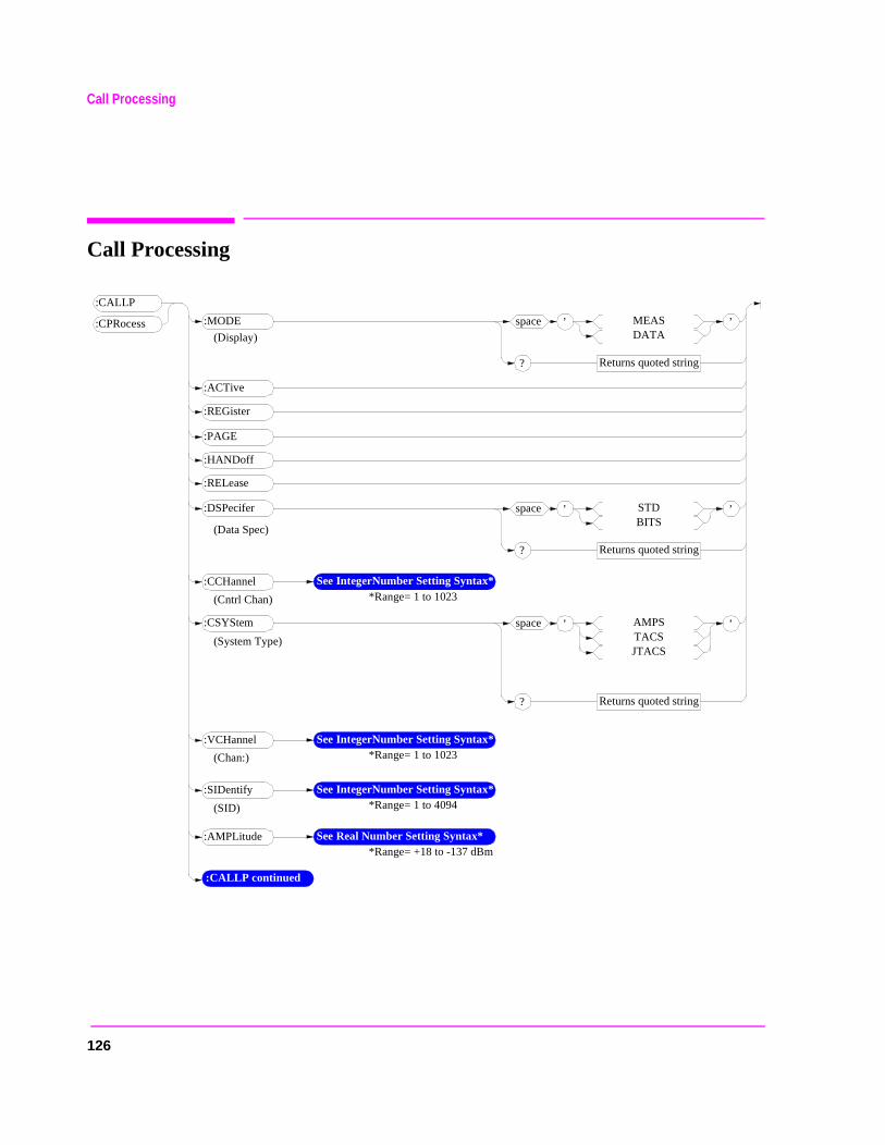
Call Processing
Call Processing
’space MEASDATA
Returns quoted string?
’
:CALLP
:CPRocess :MODE
:ACTive
’space AMPSTACSJTACS
Returns quoted string?
’:CSYStem
:REGister
:PAGE
:HANDoff
:RELease
’space STDBITS
Returns quoted string?
’:DSPecifer
(Display)
(Data Spec)
:CCHannel See IntegerNumber Setting Syntax**Range= 1 to 1023
:VCHannel See IntegerNumber Setting Syntax**Range= 1 to 1023
:SIDentify See IntegerNumber Setting Syntax**Range= 1 to 4094
:AMPLitude See Real Number Setting Syntax**Range= +18 to -137 dBm
(SID)
(Chan:)
(Cntrl Chan)
(System Type)
:CALLP continued
126
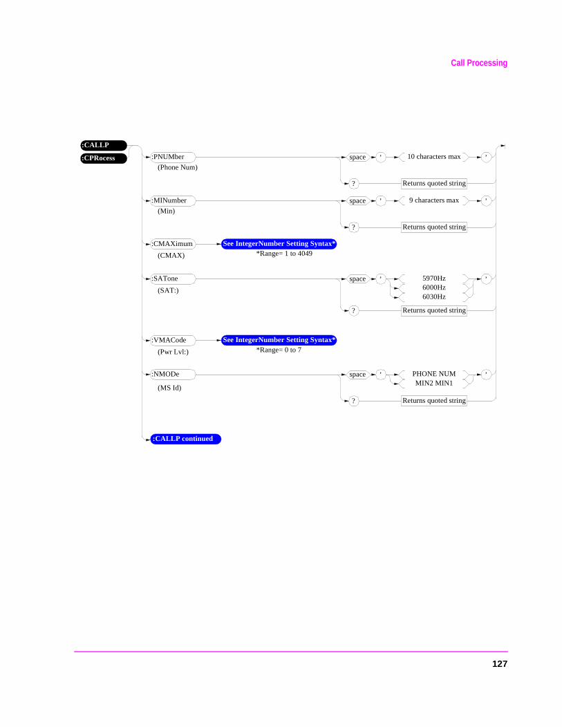
Call Processing
’space 10 characters max
Returns quoted string?
’:PNUMber
’space 5970Hz6000Hz6030Hz
Returns quoted string?
’:SATone
’space PHONE NUMMIN2 MIN1
Returns quoted string?
’:NMODe
(Phone Num)
(MS Id)
:CMAXimum See IntegerNumber Setting Syntax**Range= 1 to 4049
:VMACode See IntegerNumber Setting Syntax**Range= 0 to 7(Pwr Lvl:)
(CMAX)
(SAT:)
:CPRocess
:CALLP
’space 9 characters max
Returns quoted string?
’:MINumber
(Min)
:CALLP continued
127
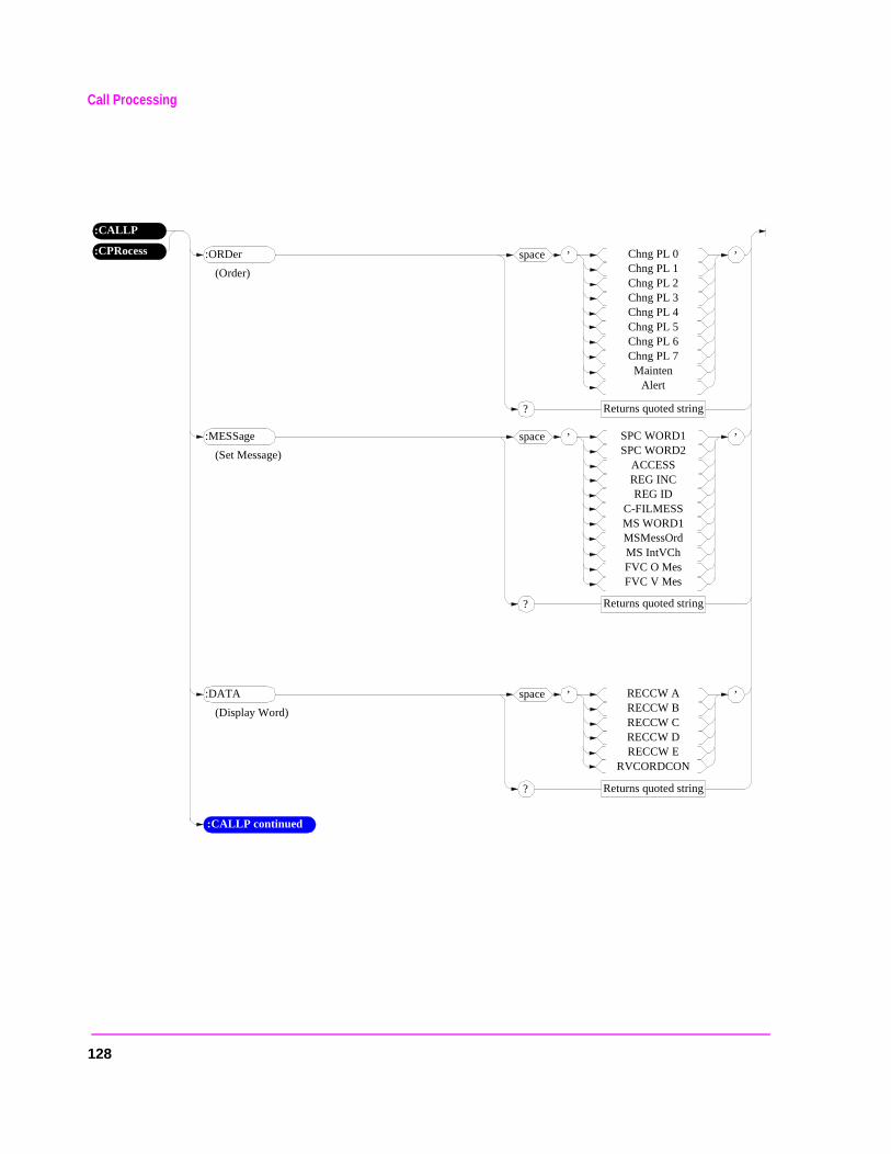
Call Processing
’space Chng PL 0Chng PL 1Chng PL 2Chng PL 3Chng PL 4Chng PL 5Chng PL 6Chng PL 7Mainten
Alert
Returns quoted string?
’:ORDer
(Order)
:CPRocess
:CALLP
’space SPC WORD1SPC WORD2
ACCESSREG INCREG ID
C-FILMESSMS WORD1MSMessOrdMS IntVChFVC O MesFVC V Mes
Returns quoted string?
’:MESSage
(Set Message)
’space RECCW ARECCW BRECCW CRECCW DRECCW E
RVCORDCON
Returns quoted string?
’:DATA
(Display Word)
:CALLP continued
128
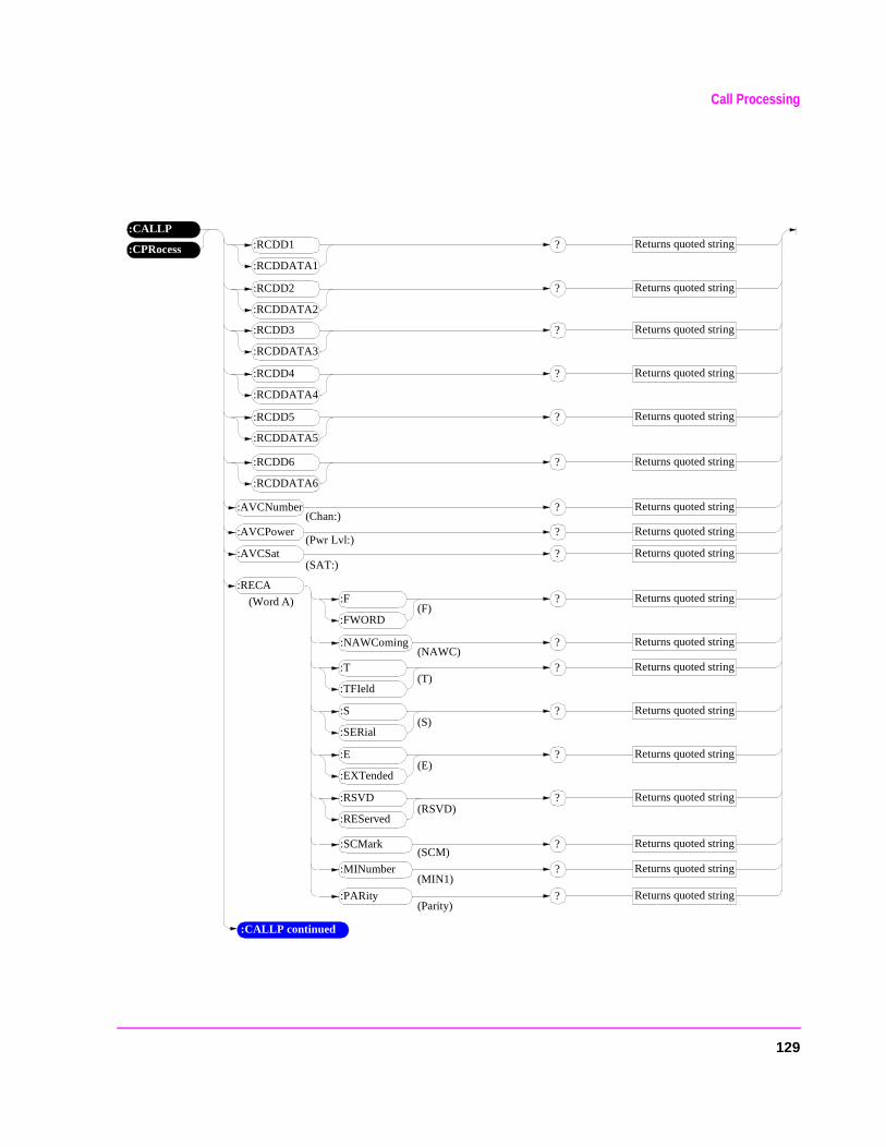
Call Processing
(Chan:)
:CPRocess
:CALLP:RCDD1
:RCDDATA1
Returns quoted string?
:RCDD2
:RCDDATA2
Returns quoted string?
:RCDD3
:RCDDATA3
Returns quoted string?
:RCDD4
:RCDDATA4
Returns quoted string?
:RCDD5
:RCDDATA5
Returns quoted string?
:RCDD6
:RCDDATA6
Returns quoted string?
:AVCNumber Returns quoted string?
:AVCPower Returns quoted string?
:AVCSat Returns quoted string?
:RECA
(Pwr Lvl:)
(SAT:)
(Word A) :F
:FWORD
Returns quoted string?
:NAWComing Returns quoted string?
:T
:TFIeld
Returns quoted string?
:S
:SERial
Returns quoted string?
:E
:EXTended
Returns quoted string?
:RSVD
:REServed
Returns quoted string?
:SCMark Returns quoted string?
:MINumber Returns quoted string?
:PARity Returns quoted string?
(F)
(NAWC)
(T)
(S)
(E)
(SCM)
(MIN1)
(Parity)
(RSVD)
:CALLP continued
129
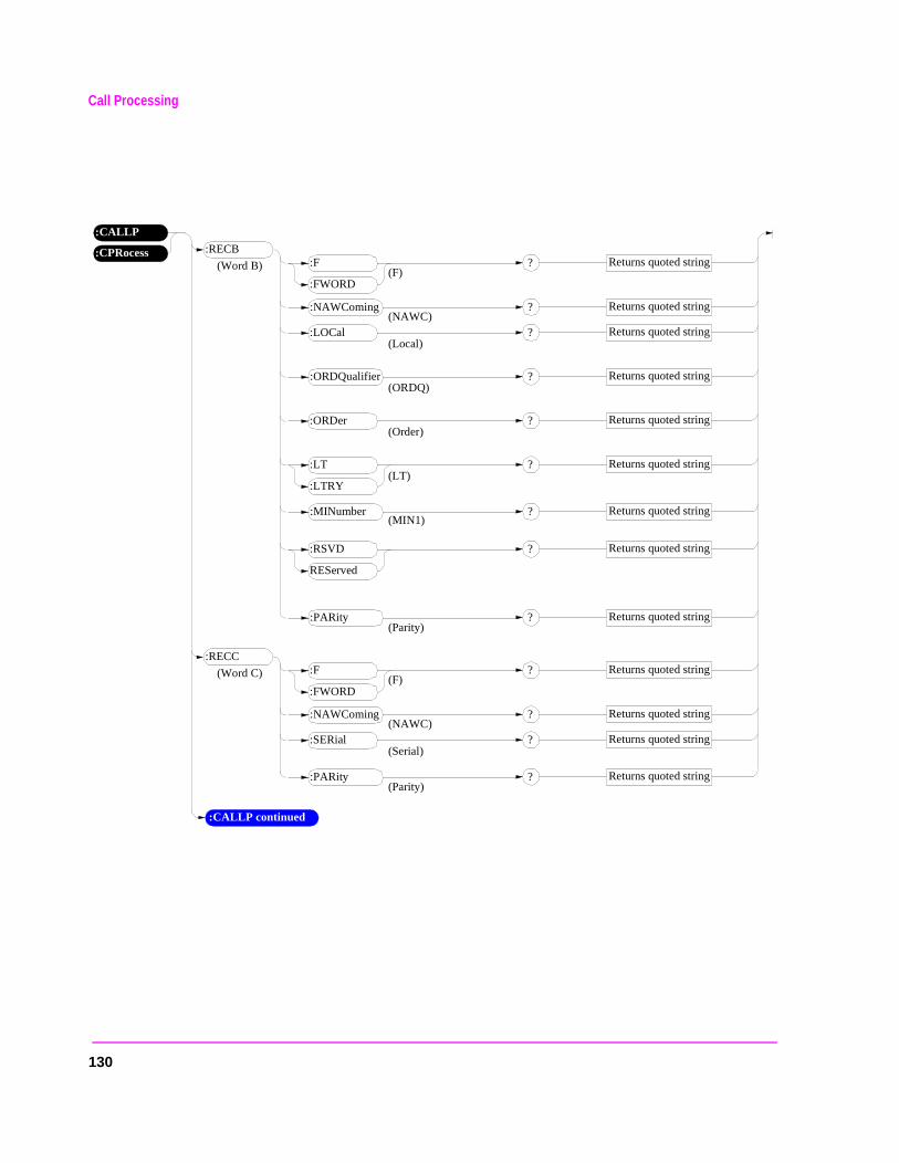
Call Processing
:CPRocess
:CALLP
:RECB
(Word B) :F
:FWORD
Returns quoted string?
:NAWComing Returns quoted string?
:LOCal Returns quoted string?
:ORDQualifier Returns quoted string?
:ORDer Returns quoted string?
:LT
:LTRY
Returns quoted string?
:MINumber Returns quoted string?
:PARity Returns quoted string?
(F)
(NAWC)
(Local)
(ORDQ)
(Order)
(MIN1)
(Parity)
(LT)
:RECC
(Word C) :F
:FWORD
Returns quoted string?
:NAWComing Returns quoted string?
:SERial Returns quoted string?
:PARity Returns quoted string?
(F)
(NAWC)
(Serial)
(Parity)
:CALLP continued
:RSVD
REServed
Returns quoted string?
130
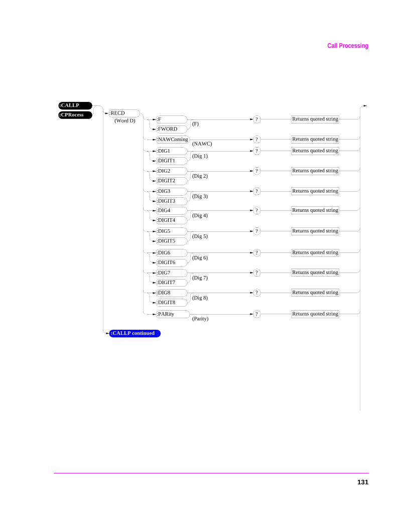
Call Processing
:CPRocess
:CALLP
:RECD
(Word D) :F
:FWORD
Returns quoted string?
:NAWComing Returns quoted string?
:DIG1
:DIGIT1
Returns quoted string?
:DIG2
:DIGIT2
Returns quoted string?
:PARity Returns quoted string?
(F)
(NAWC)
(Dig 1)
(Dig 2)
(Parity)
:DIG3
:DIGIT3
Returns quoted string?(Dig 3)
:DIG4
:DIGIT4
Returns quoted string?(Dig 4)
:DIG5
:DIGIT5
Returns quoted string?(Dig 5)
:DIG6
:DIGIT6
Returns quoted string?(Dig 6)
:DIG7
:DIGIT7
Returns quoted string?(Dig 7)
:DIG8
:DIGIT8
Returns quoted string?(Dig 8)
:CALLP continued
131
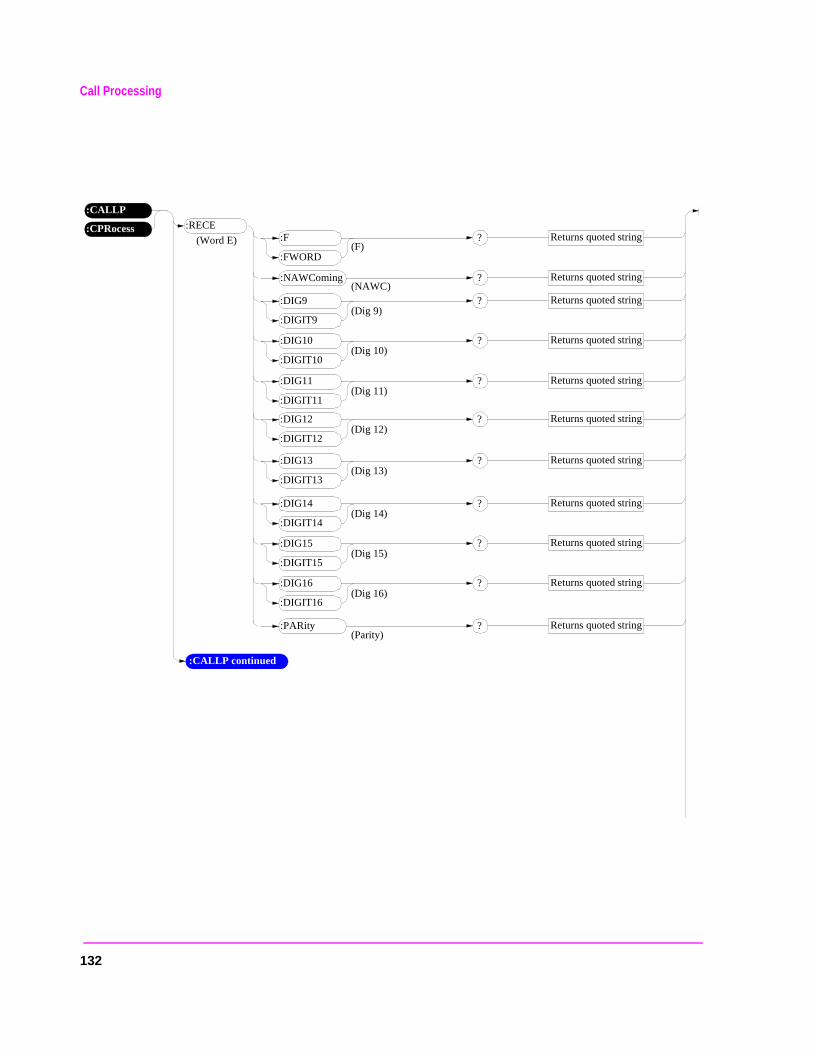
Call Processing
:CPRocess
:CALLP
:RECE
(Word E) :F
:FWORD
Returns quoted string?
:NAWComing Returns quoted string?
:DIG9
:DIGIT9
Returns quoted string?
:DIG10
:DIGIT10
Returns quoted string?
:PARity Returns quoted string?
(F)
(NAWC)
(Dig 9)
(Dig 10)
(Parity)
:DIG11
:DIGIT11
Returns quoted string?(Dig 11)
:DIG12
:DIGIT12
Returns quoted string?(Dig 12)
:DIG13
:DIGIT13
Returns quoted string?(Dig 13)
:DIG14
:DIGIT14
Returns quoted string?(Dig 14)
:DIG15
:DIGIT15
Returns quoted string?(Dig 15)
:DIG16
:DIGIT16
Returns quoted string?(Dig 16)
:CALLP continued
132
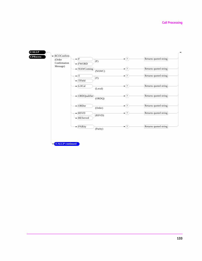
Call Processing
:CPRocess
:CALLP
:RCOConfirm
(Order Confirmation Message)
:F
:FWORD
Returns quoted string?
:NAWComing Returns quoted string?
:LOCal Returns quoted string?
:ORDQualifier Returns quoted string?
:ORDer Returns quoted string?
:PARity Returns quoted string?
(F)
(NAWC)
(Local)
(ORDQ)
(Order)
(Parity)
:T
:TFIeld
Returns quoted string?(T)
:RSVD
:REServed
Returns quoted string?(RSVD)
:CALLP continued
133
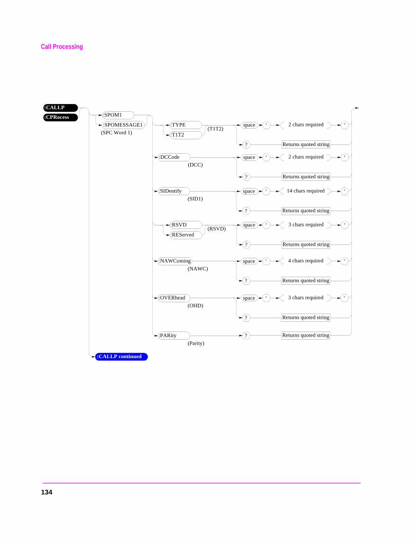
Call Processing
’space 2 chars required
Returns quoted string?
’
:CPRocess
:CALLP:SPOM1
:SPOMESSAGE1(T1T2)
:TYPE
:T1T2
:DCCode
(DCC)
’space 2 chars required
Returns quoted string?
’(SPC Word 1)
’space 14 chars required
Returns quoted string?
’:SIDentify
(SID1)
(RSVD):RSVD
:REServed
’space 3 chars required
Returns quoted string?
’
’space 4 chars required
Returns quoted string?
’:NAWComing
(NAWC)
’space 3 chars required
Returns quoted string?
’:OVERhead
(OHD)
Returns quoted string?:PARity
(Parity)
:CALLP continued
134
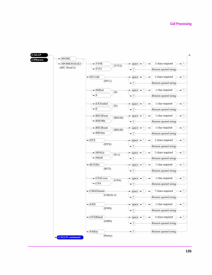
Call Processing
’space 2 chars required
Returns quoted string?
’
:CPRocess
:CALLP:SPOM2
:SPOMESSAGE2(T1T2)
:TYPE
:T1T2
:DCCode
(DCC)
’space 2 chars required
Returns quoted string?
’(SPC Word 2)
Returns quoted string?:PARity
(Parity)
(S):SERial
:S
’space 1 char required
Returns quoted string?
’
(E):EXTended
:E
’space 1 char required
Returns quoted string?
’
(REGH):REGHome
:RHOMe
’space 1 char required
Returns quoted string?
’
(REGR):REGRoam
:RROam
’space 1 char required
Returns quoted string?
’
’space 2 chars required
Returns quoted string?
’:DTX
(DTX)
(N-1):NPAGe
:Nfield
’space 5 chars required
Returns quoted string?
’
’space 1 char required
Returns quoted string?
’:RCFiller
(RCF)
(CPA):CPACcess
:CPA
’space 1 char required
Returns quoted string?
’
’space 7 chars required
Returns quoted string?
’:CMAXimum
(CMAX-1)
’space 1 char required
Returns quoted string?
’:END
(END)
’space 3 chars required
Returns quoted string?
’:OVERhead
(OHD)
:CALLP continued
135
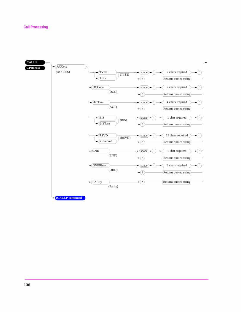
Call Processing
’space 2 chars required
Returns quoted string?
’
:CPRocess
:CALLP:ACCess
(T1T2):TYPE
:T1T2
:DCCode
(DCC)
’space 2 chars required
Returns quoted string?
’(ACCESS)
Returns quoted string?:PARity
(Parity)
(ACT)
:ACTion ’space 4 chars required
Returns quoted string?
’
(BIS):BIS
:BISTate
’space 1 char required
Returns quoted string?
’
(RSVD):RSVD
:REServed
’space 15 chars required
Returns quoted string?
’
’space 1 char required
Returns quoted string?
’:END
(END)
’space 3 chars required
Returns quoted string?
’:OVERhead
(OHD)
:CALLP continued
136
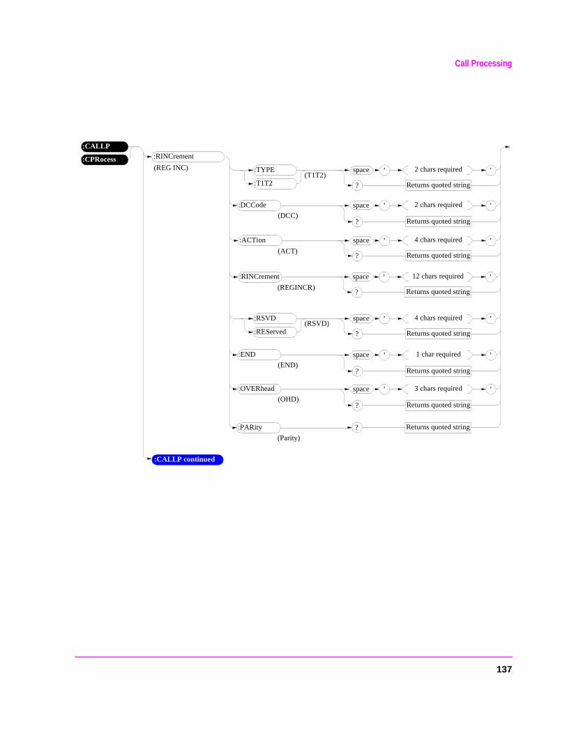
Call Processing
’space 2 chars required
Returns quoted string?
’
:CPRocess
:CALLP:RINCrement
(T1T2):TYPE
:T1T2
:DCCode
(DCC)
’space 2 chars required
Returns quoted string?
’(REG INC)
Returns quoted string?:PARity
(Parity)
(ACT)
:ACTion ’space 4 chars required
Returns quoted string?
’
(RSVD):RSVD
:REServed
’space 4 chars required
Returns quoted string?
’
’space 1 char required
Returns quoted string?
’:END
(END)
’space 3 chars required
Returns quoted string?
’:OVERhead
(OHD)
(REGINCR)
:RINCrement ’space 12 chars required
Returns quoted string?
’
:CALLP continued
137
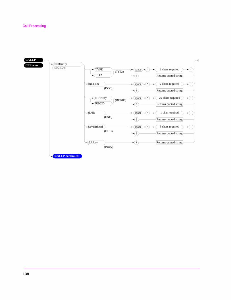
Call Processing
’space 2 chars required
Returns quoted string?
’
:CPRocess
:CALLP:RIDentify
(T1T2):TYPE
:T1T2
:DCCode
(DCC)
’space 2 chars required
Returns quoted string?
’(REG ID)
Returns quoted string?:PARity
(Parity)
(REGID):IDENtify
:REGID
’space 20 chars required
Returns quoted string?
’
’space 1 char required
Returns quoted string?
’:END
(END)
’space 3 chars required
Returns quoted string?
’:OVERhead
(OHD)
:CALLP continued
138
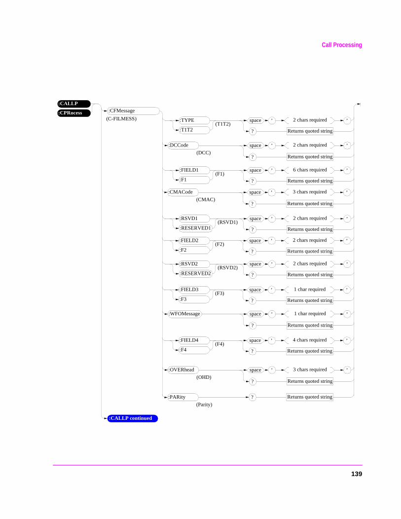
Call Processing
’space 2 chars required
Returns quoted string?
’
:CPRocess
:CALLP:CFMessage
(T1T2):TYPE
:T1T2
:DCCode
(DCC)
’space 2 chars required
Returns quoted string?
’(C-FILMESS)
Returns quoted string?:PARity
(Parity)
(F1):FIELD1
:F1
’space 6 chars required
Returns quoted string?
’
(RSVD1):RSVD1
:RESERVED1
’space 2 chars required
Returns quoted string?
’
’space 1 char required
Returns quoted string?
’:WFOMessage
’space 3 chars required
Returns quoted string?
’:OVERhead
(OHD)
’space 3 chars required
Returns quoted string?
’:CMACode
(CMAC)
(F2):FIELD2
:F2
’space 2 chars required
Returns quoted string?
’
(RSVD2):RSVD2
:RESERVED2
’space 2 chars required
Returns quoted string?
’
(F3):FIELD3
:F3
’space 1 char required
Returns quoted string?
’
(F4):FIELD4
:F4
’space 4 chars required
Returns quoted string?
’
:CALLP continued
139
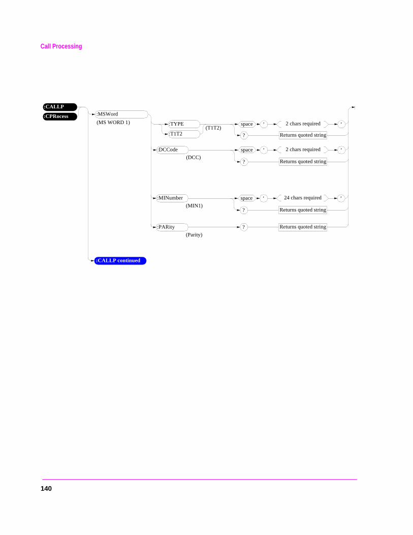
Call Processing
’space 2 chars required
Returns quoted string?
’
:CPRocess
:CALLP:MSWord
(T1T2):TYPE
:T1T2
:DCCode
(DCC)
’space 2 chars required
Returns quoted string?
’(MS WORD 1)
Returns quoted string?:PARity
(Parity)
’space 24 chars required
Returns quoted string?
’:MINumber
(MIN1)
:CALLP continued
140
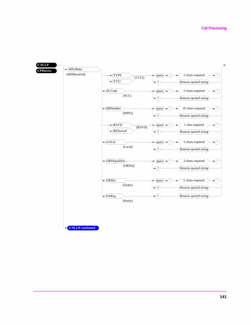
Call Processing
’space 2 chars required
Returns quoted string?
’
:CPRocess
:CALLP:MSORder
(T1T2):TYPE
:T1T2
:SCCode
(SCC)
’space 2 chars required
Returns quoted string?
’(MSMessOrd)
Returns quoted string?:PARity
(Parity)
(RSVD):RSVD
:REServed
’space 1 char required
Returns quoted string?
’
’space 5 chars required
Returns quoted string?
’:LOCal
(Local)
’space 3 chars required
Returns quoted string?
’:ORDQualifier
(ORDQ)
’space 10 chars required
Returns quoted string?
’:MINumber
(MIN2)
’space 5 chars required
Returns quoted string?
’:ORDer
(Order)
:CALLP continued
141
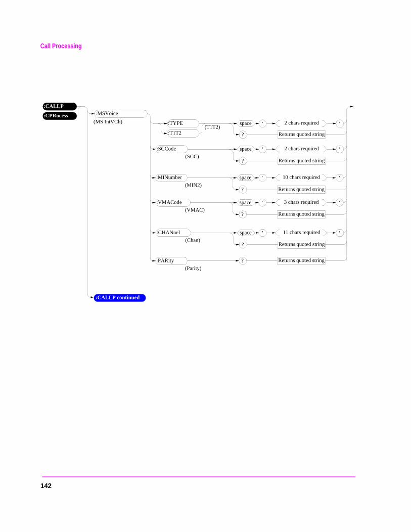
Call Processing
’space 2 chars required
Returns quoted string?
’
:CPRocess
:CALLP:MSVoice
(T1T2):TYPE
:T1T2
:SCCode
(SCC)
’space 2 chars required
Returns quoted string?
’(MS IntVCh)
Returns quoted string?:PARity
(Parity)
’space 11 chars required
Returns quoted string?
’:CHANnel
(Chan)
’space 10 chars required
Returns quoted string?
’:MINumber
(MIN2)
’space 3 chars required
Returns quoted string?
’:VMACode
(VMAC)
:CALLP continued
142
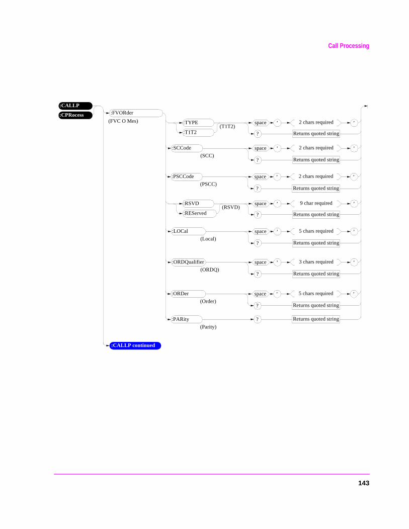
Call Processing
’space 2 chars required
Returns quoted string?
’
:CPRocess
:CALLP:FVORder
(T1T2):TYPE
:T1T2
:SCCode
(SCC)
’space 2 chars required
Returns quoted string?
’(FVC O Mes)
Returns quoted string?:PARity
(Parity)
(RSVD):RSVD
:REServed
’space 9 char required
Returns quoted string?
’
’space 5 chars required
Returns quoted string?
’:LOCal
(Local)
’space 3 chars required
Returns quoted string?
’:ORDQualifier
(ORDQ)
’space 2 chars required
Returns quoted string?
’:PSCCode
(PSCC)
’space 5 chars required
Returns quoted string?
’:ORDer
(Order)
:CALLP continued
143
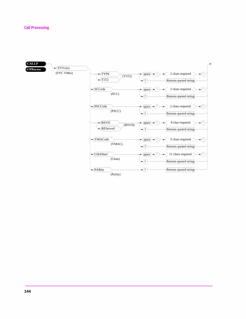
Call Processing
’space 2 chars required
Returns quoted string?
’
:CPRocess
:CALLP:FVVoice
(T1T2):TYPE
:T1T2
:SCCode
(SCC)
’space 2 chars required
Returns quoted string?
’(FVC VMes)
Returns quoted string?:PARity
(Parity)
(RSVD):RSVD
:REServed
’space 8 char required
Returns quoted string?
’
’space 3 chars required
Returns quoted string?
’:VMACode
(VMAC)
’space 2 chars required
Returns quoted string?
’:PSCCode
(PSCC)
’space 11 chars required
Returns quoted string?
’:CHANnel
(Chan)
144
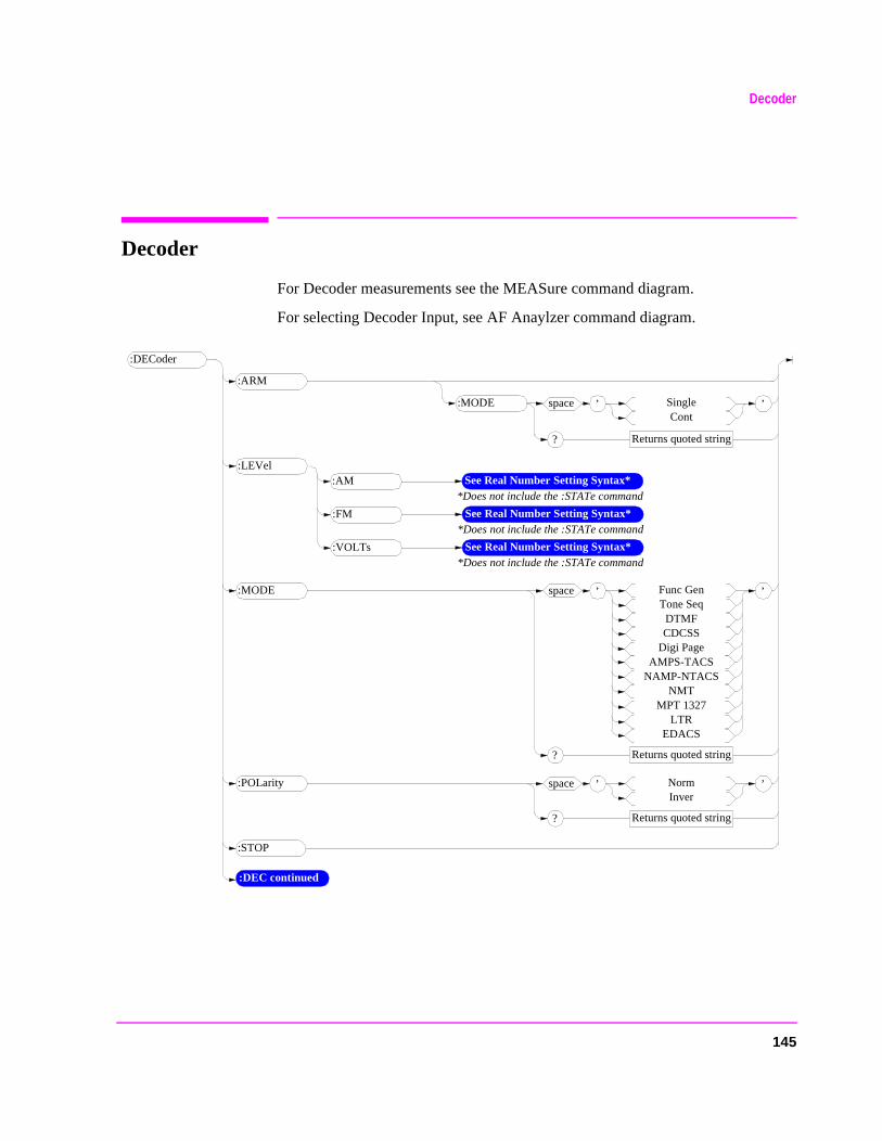
Decoder
Decoder
For Decoder measurements see the MEASure command diagram.
For selecting Decoder Input, see AF Anaylzer command diagram.
See Real Number Setting Syntax**Does not include the :STATe command
:DECoder
’space SingleCont
Returns quoted string?
’
:ARM
’space Func GenTone Seq
DTMFCDCSS
Digi PageAMPS-TACS
NAMP-NTACSNMT
MPT 1327LTR
EDACS
Returns quoted string?
’:MODE
:STOP
’space NormInver
Returns quoted string?
’:POLarity
:DEC continued
:MODE
:AM:LEVel
See Real Number Setting Syntax**Does not include the :STATe command
:FM
See Real Number Setting Syntax**Does not include the :STATe command
:VOLTs
145
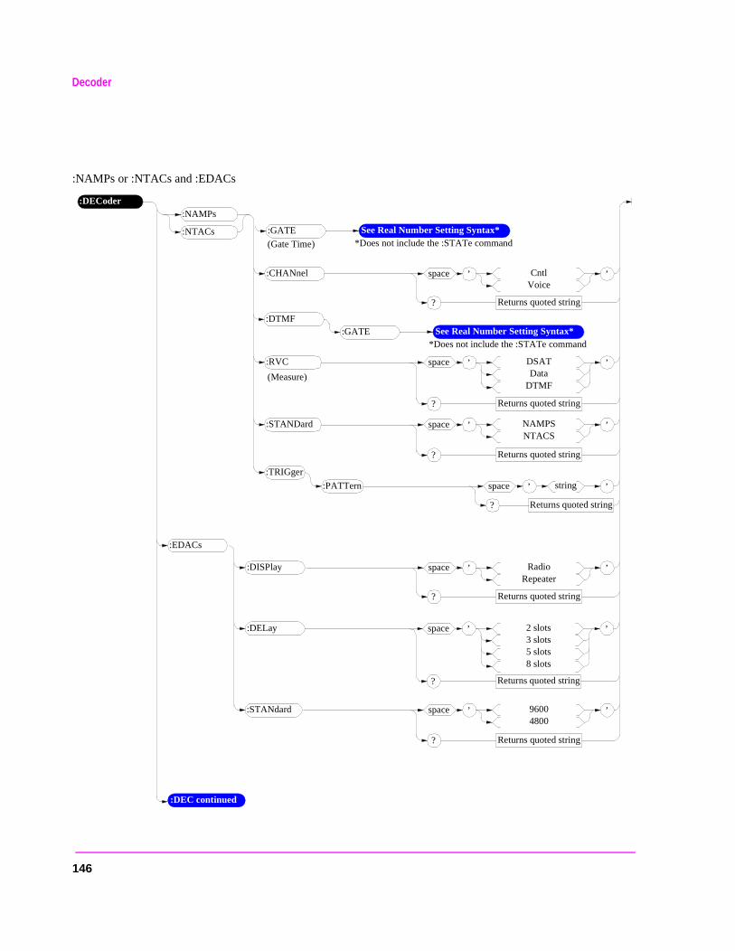
Decoder
:NAMPs or :NTACs and :EDACs
’space NAMPSNTACS
Returns quoted string?
’
:DECoder
:STANDard
’space CntlVoice
Returns quoted string?
’:CHANnel
:NAMPs
:NTACs
:PATTern
:TRIGger
’space string
Returns quoted string?
’
:GATE See Real Number Setting Syntax**Does not include the :STATe command(Gate Time)
:DTMF:GATE See Real Number Setting Syntax*
*Does not include the :STATe command
’space DSATData
DTMF
Returns quoted string?
’:RVC
(Measure)
:EDACs
’space RadioRepeater
Returns quoted string?
’:DISPlay
’space 96004800
Returns quoted string?
’:STANdard
:DEC continued
’space 2 slots3 slots5 slots8 slots
Returns quoted string?
’:DELay
146
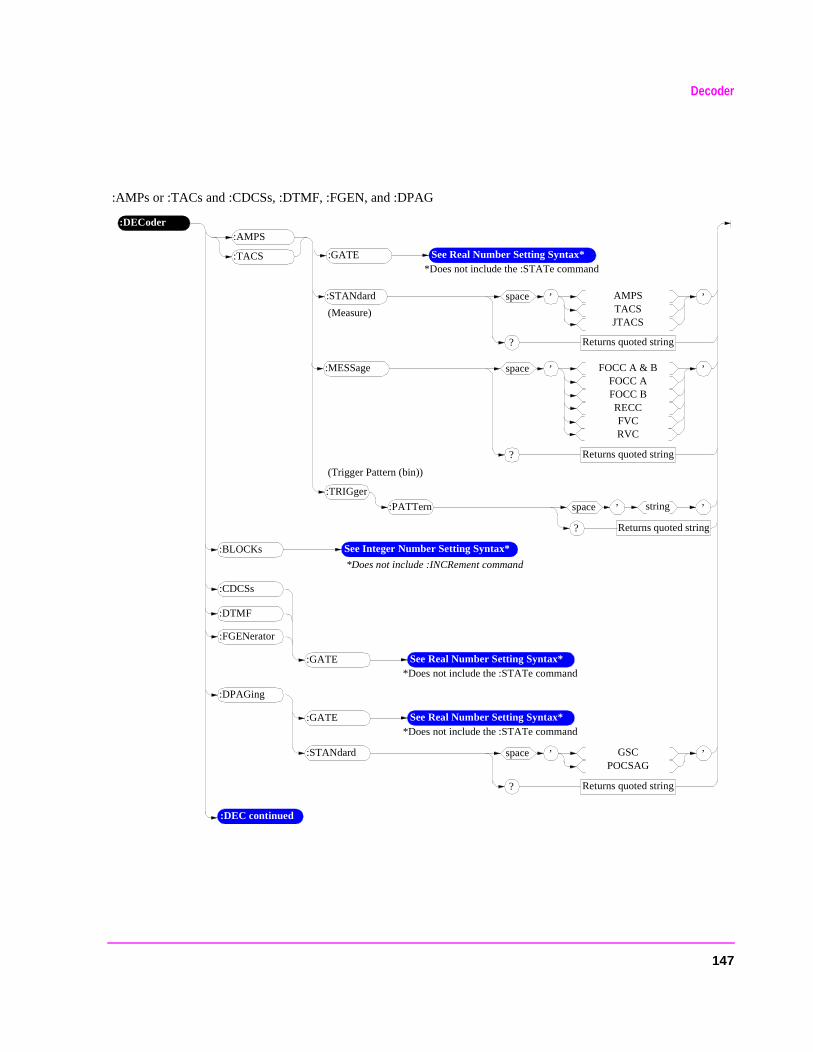
Decoder
:AMPs or :TACs and :CDCSs, :DTMF, :FGEN, and :DPAG
:DECoder:AMPS
:TACS
:PATTern
:TRIGger
’space string
Returns quoted string?
’
:GATE See Real Number Setting Syntax**Does not include the :STATe command
’space AMPSTACSJTACS
Returns quoted string?
’:STANdard
(Measure)
:DEC continued
’space FOCC A & BFOCC AFOCC BRECCFVCRVC
Returns quoted string?
’:MESSage
(Trigger Pattern (bin))
:CDCSs
:FGENerator
:DTMF
:GATE See Real Number Setting Syntax**Does not include the :STATe command
*Does not include :INCRement command
:BLOCKs See Integer Number Setting Syntax*
’space GSCPOCSAG
Returns quoted string?
’:STANdard
:DPAGing
:GATE See Real Number Setting Syntax**Does not include the :STATe command
147
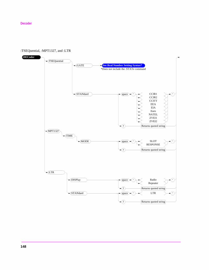
Decoder
:TSEQuential, :MPT1327, and :LTR
:DECoder
:TSEQuential
:GATE See Real Number Setting Syntax**Does not include the :STATe command
’space LTR
Returns quoted string?
’:STANdard
:LTR
’space CCIR1CCIR2CCITTEEAEIAEuro
NATELZVEI1ZVEI2
Returns quoted string?
’:STANdard
’space SLOTRESPONSE
Returns quoted string?
’:MODE
:MPT1327
:TIME
’space RadioRepeater
Returns quoted string?
’:DISPlay
148
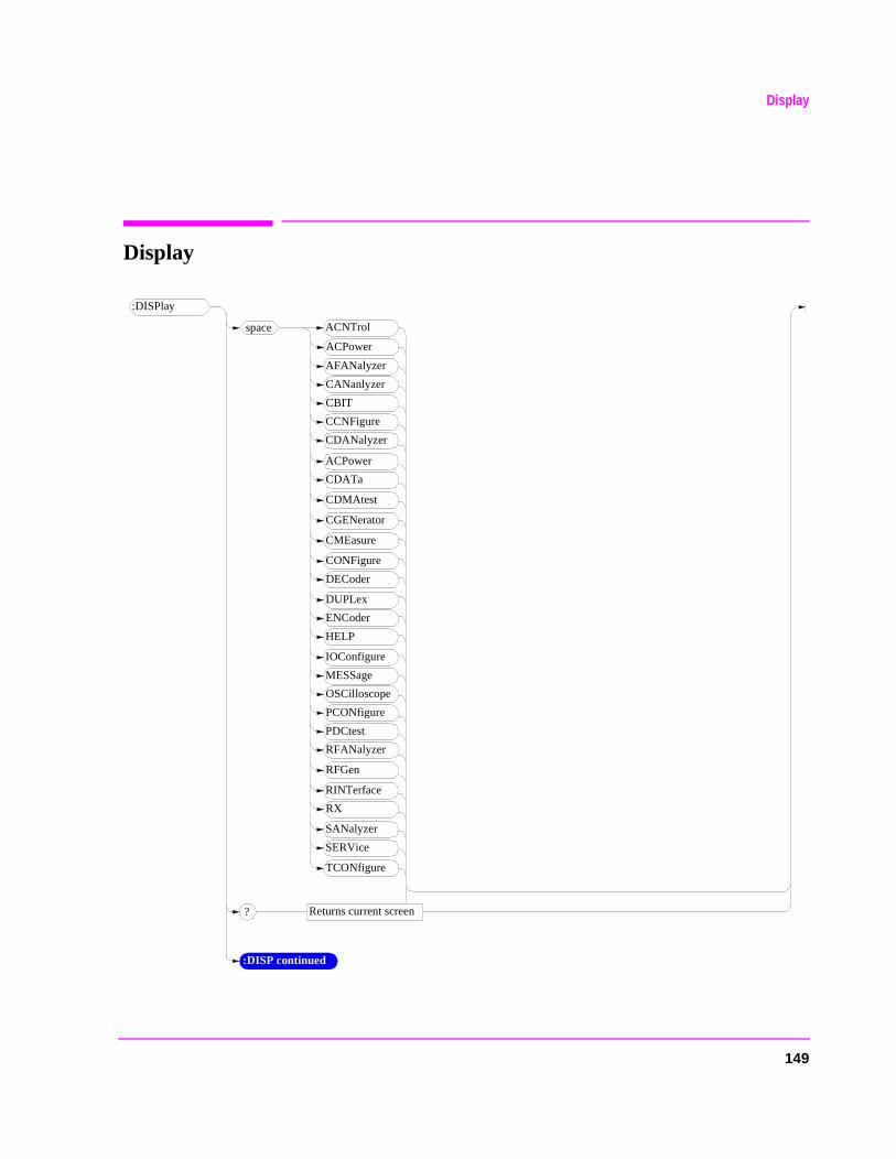
Display
Display
:DISPlay
:DISP continued
space ACNTrol
ACPower
AFANalyzer
CANanlyzer
CBIT
CCNFigure
CDANalyzer
ACPower
CDATa
CDMAtest
CGENerator
CMEasure
CONFigure
DECoder
DUPLex
ENCoder
HELP
IOConfigure
MESSage
OSCilloscope
PCONfigure
PDCtest
RFANalyzer
RFGen
RINTerface
RX
SANalyzer
SERVice
TCONfigure
Returns current screen?
149
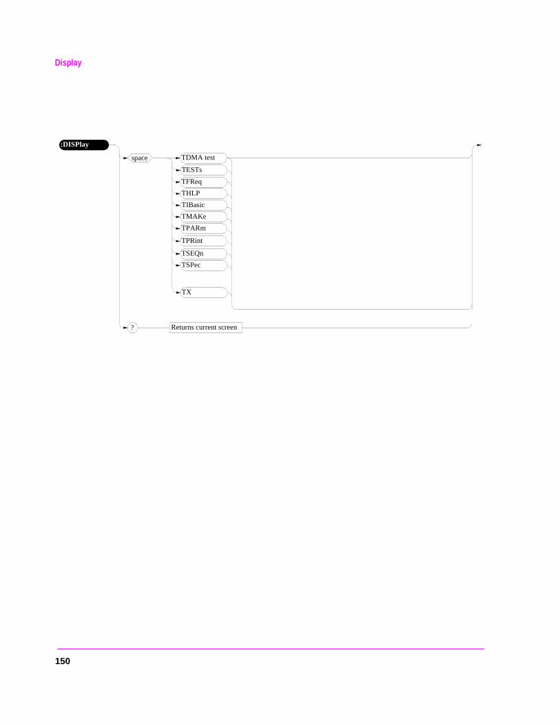
Display
:DISPlay
space TDMA test
TESTs
TFReq
THLP
TIBasic
TMAKe
TPARm
TPRint
TSEQn
TSPec
Returns current screen?
TX
150
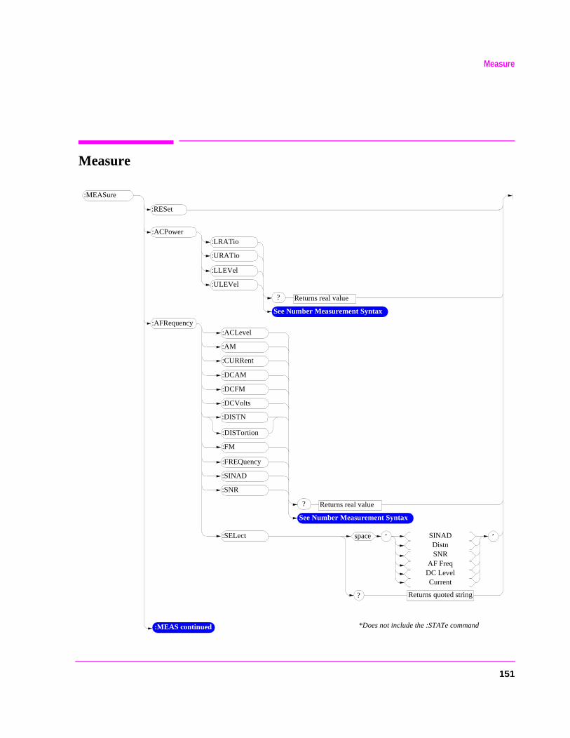
Measure
Measure
:MEASure
:MEAS continued
:LRATio
*Does not include the :STATe command
’space SINADDistnSNR
AF FreqDC LevelCurrent
Returns quoted string?
’
:URATio
:LLEVel
:ULEVel
? Returns real value
See Number Measurement Syntax
:RESet
:ACPower
:DISTN
? Returns real value
See Number Measurement Syntax
:AFRequency
:DISTortion
:DCAM
:AM
:ACLevel
:DCFM
:DCVolts
:CURRent
:FM
:FREQuency
:SINAD
:SNR
:SELect
151
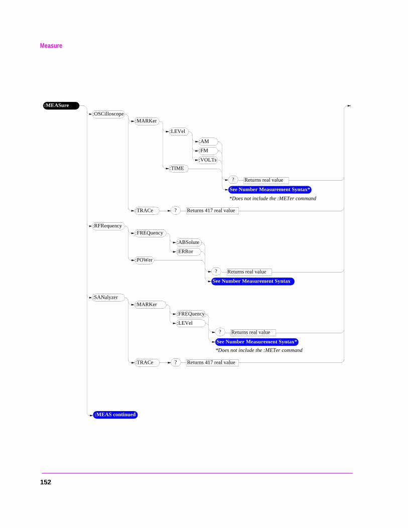
Measure
:MEASure
:MEAS continued
:MARKer
*Does not include the :METer command
:TRACe
? Returns real value
See Number Measurement Syntax*
:OSCilloscope
:LEVel
:TIME
:AM
:FM
:VOLTs
? Returns 417 real value
:FREQuency
? Returns real value
See Number Measurement Syntax
:RFRequency
:POWer
:ABSolute
:ERRor
:MARKer
? Returns real value
See Number Measurement Syntax*
:SANalyzer
:FREQuency
:LEVel
:TRACe ? Returns 417 real value
*Does not include the :METer command
152
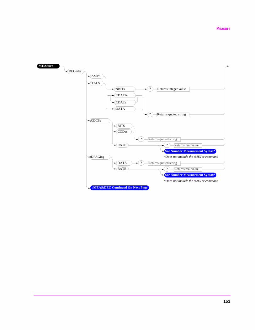
Measure
:MEASure
:MEAS:DEC Continued On Next Page
:DECoder
? Returns integer value
? Returns real value
See Number Measurement Syntax*
:CDCSs
:RATE
:BITS
:CODes
:AMPS
:TACS
:CDATA
:CDATa
:NBITs
:DATA
? Returns quoted string
*Does not include the :METer command
? Returns real value
See Number Measurement Syntax*
:DPAGing
:RATE
:DATA ? Returns quoted string
*Does not include the :METer command
? Returns quoted string
153
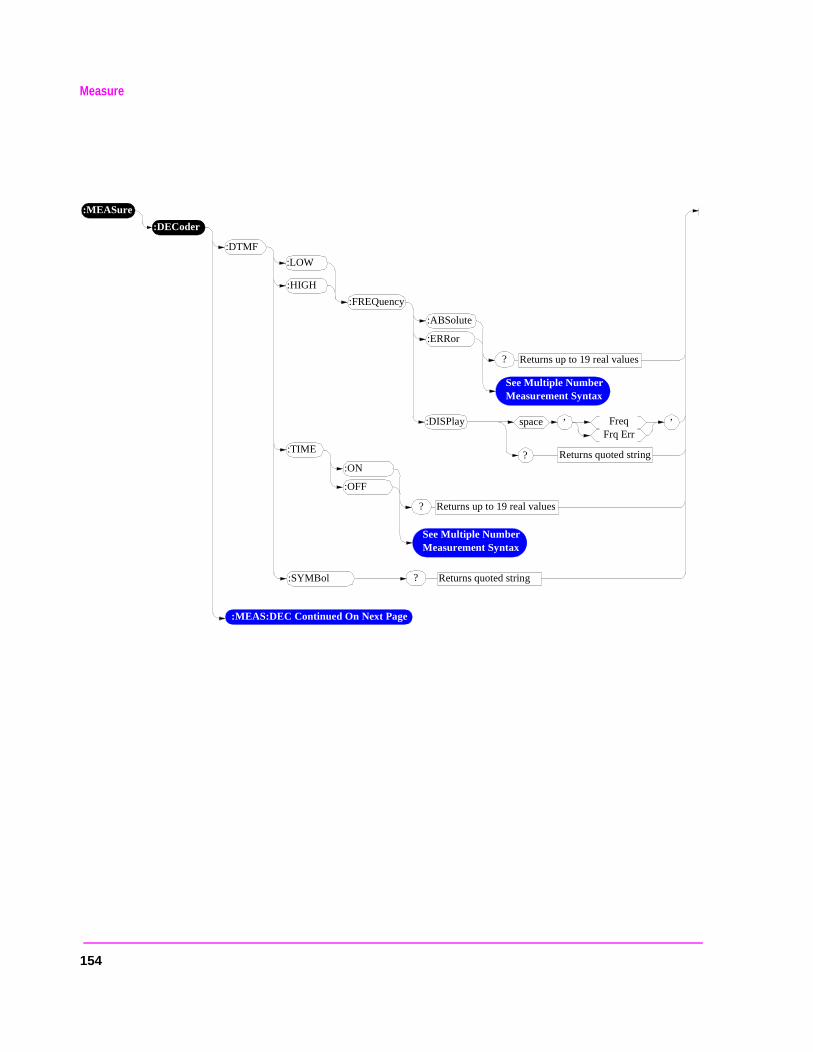
Measure
:MEASure
:DECoder
:DTMF
:LOW
:HIGH
:FREQuency
:ABSolute
:ERRor
? Returns up to 19 real values
See Multiple Number Measurement Syntax
? Returns up to 19 real values
See Multiple Number Measurement Syntax
:TIME
:ON
:OFF
’space FreqFrq Err
Returns quoted string?
’:DISPlay
? Returns quoted string:SYMBol
:MEAS:DEC Continued On Next Page
154
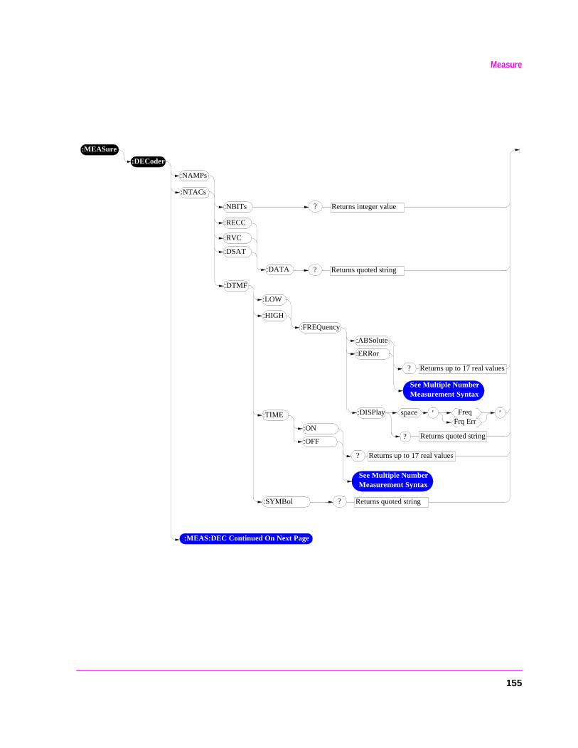
Measure
:MEASure
:DECoder
:NAMPs
:LOW
:HIGH
:FREQuency
:ABSolute
:ERRor
? Returns up to 17 real values
See Multiple Number Measurement Syntax
? Returns up to 17 real values
See Multiple Number Measurement Syntax
:TIME
:ON
:OFF
’space FreqFrq Err
Returns quoted string?
’:DISPlay
? Returns quoted string:SYMBol
:MEAS:DEC Continued On Next Page
:NTACs
:DTMF
? Returns integer value:NBITs
:DSAT
? Returns quoted string
:RECC
:RVC
:DATA
155
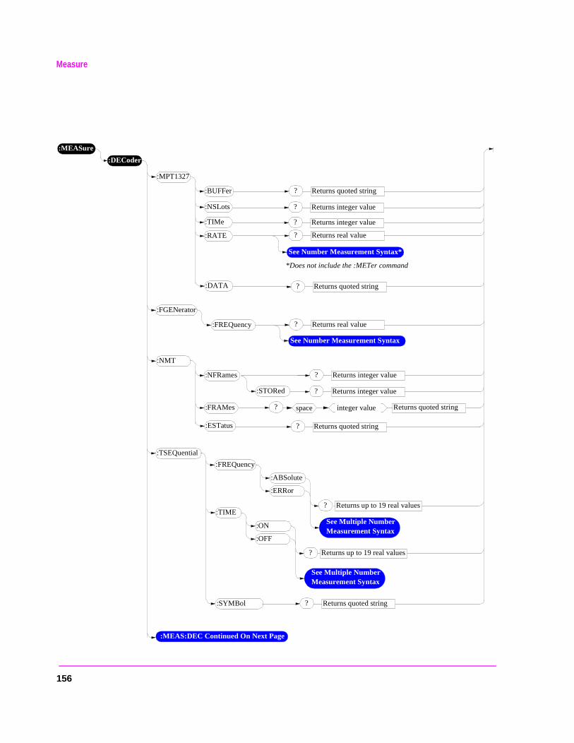
Measure
:MEASure
:DECoder
:MEAS:DEC Continued On Next Page
:MPT1327
? Returns quoted string:BUFFer
:RATE
:NSLots
:TIMe
:DATA
? Returns real value
? Returns integer value
? Returns integer value
:FREQuency ? Returns real value
:FGENerator
? Returns quoted string
See Number Measurement Syntax
:NMT
? Returns integer value:NFRames
:FRAMes
:ESTatus
? Returns quoted string
? Returns integer value
? Returns quoted string
space integer value
:TSEQuential
:FREQuency
:ABSolute
:ERRor
? Returns up to 19 real values
See Multiple Number Measurement Syntax
? Returns up to 19 real values
See Multiple Number Measurement Syntax
:TIME
:ON
:OFF
? Returns quoted string:SYMBol
See Number Measurement Syntax*
*Does not include the :METer command
:STORed
156
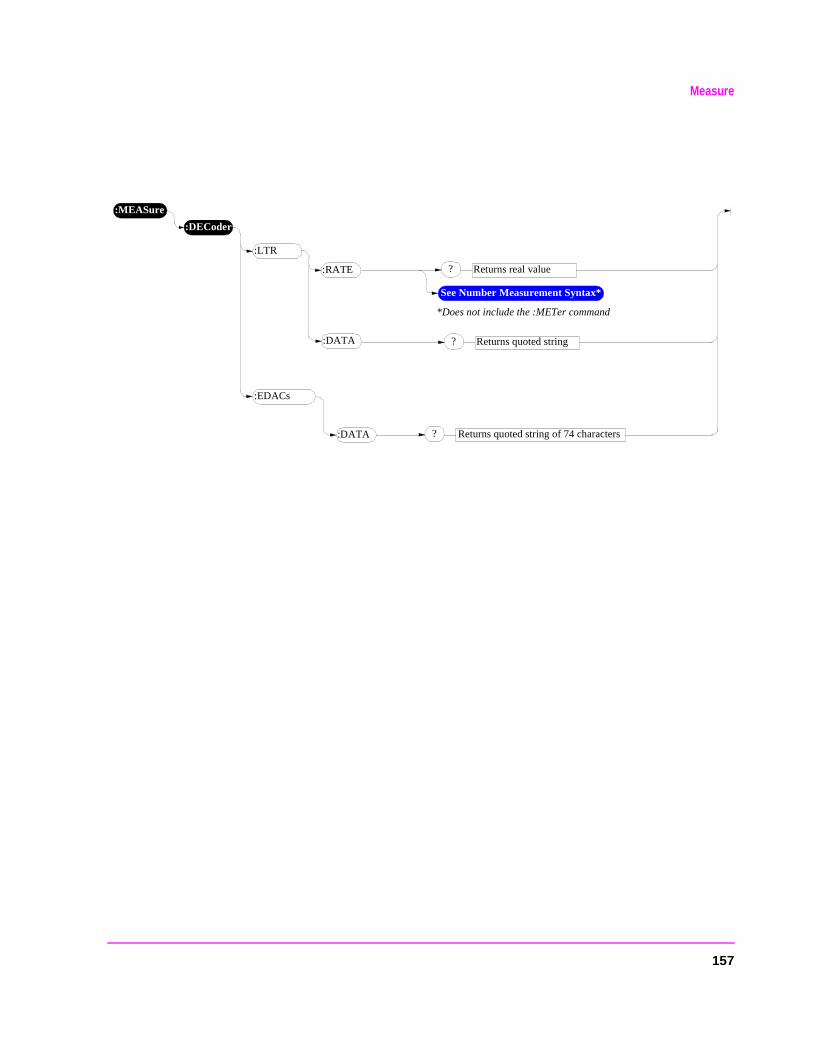
Measure
:MEASure
:DECoder
:LTR
:RATE
:DATA
? Returns real value
:EDACs
? Returns quoted string of 74 characters
? Returns quoted string
See Number Measurement Syntax*
*Does not include the :METer command
:DATA
157
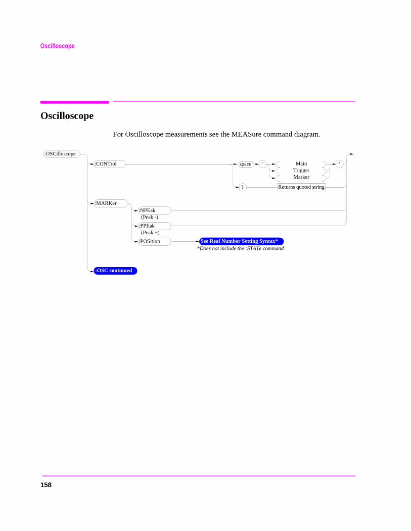
Oscilloscope
Oscilloscope
For Oscilloscope measurements see the MEASure command diagram.
:OSCilloscope
:OSC continued
:NPEak:MARKer
:PPEak
See Real Number Setting Syntax**Does not include the :STATe command
:POSition
’space MainTriggerMarker
Returns quoted string?
’:CONTrol
(Peak -)
(Peak +)
158
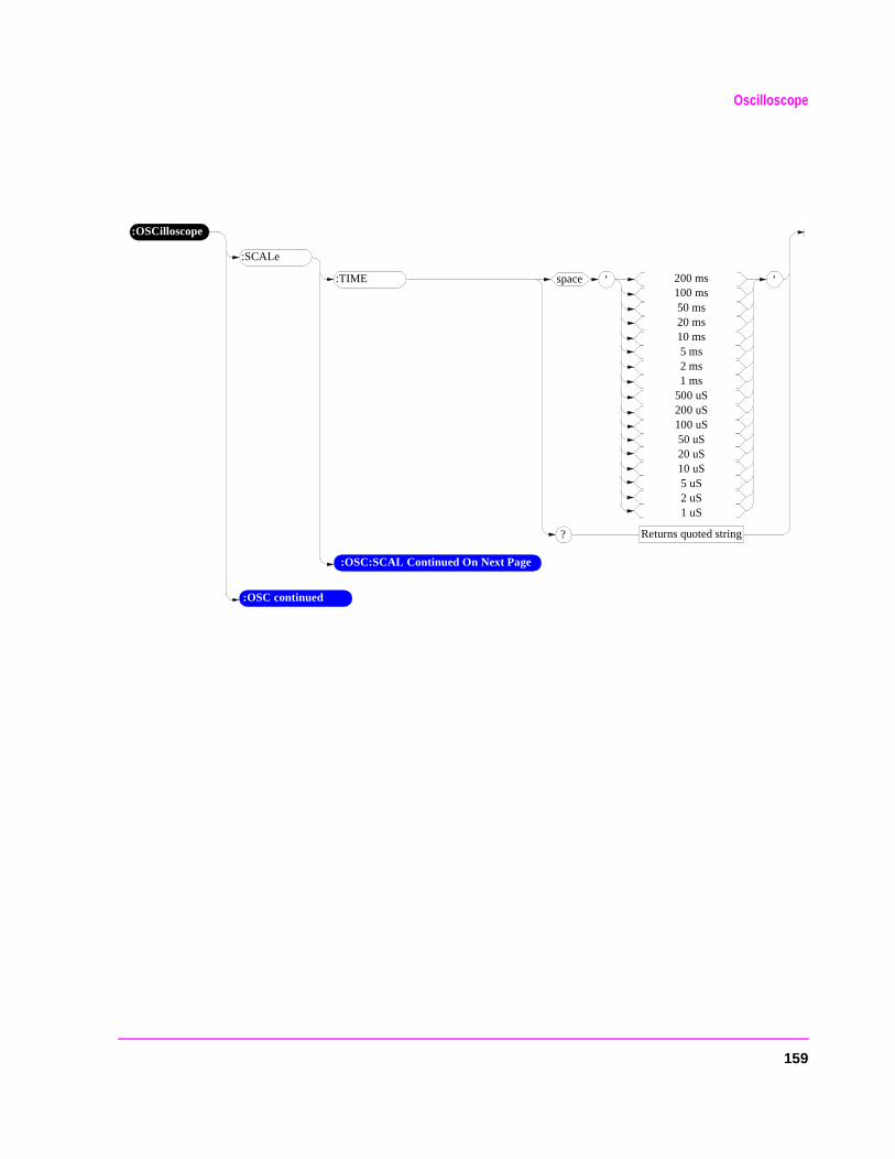
Oscilloscope
:OSCilloscope
’space 200 ms100 ms50 ms20 ms10 ms5 ms2 ms1 ms
500 uS200 uS100 uS50 uS20 uS10 uS5 uS2 uS1 uS
Returns quoted string?
’
:SCALe
:TIME
:OSC continued
:OSC:SCAL Continued On Next Page
159
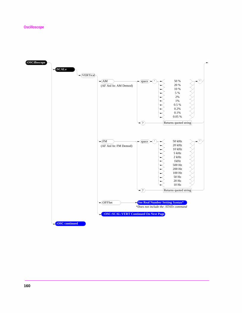
Oscilloscope
:OSCilloscope
’space 50 %20 %10 %5 %2%1%
0.5 %0.2%0.1%
0.05 %
Returns quoted string?
’
:SCALe
:VERTical
:AM
(AF Anl In: AM Demod)
’space 50 kHz20 kHz10 kHz5 kHz2 kHz1kHz
500 Hz200 Hz100 Hz50 Hz20 Hz10 Hz
Returns quoted string?
’:FM
(AF Anl In: FM Demod)
:OSC continued
:OSC:SCAL:VERT Continued On Next Page
See Real Number Setting Syntax**Does not include the :STATe command
:OFFSet
160
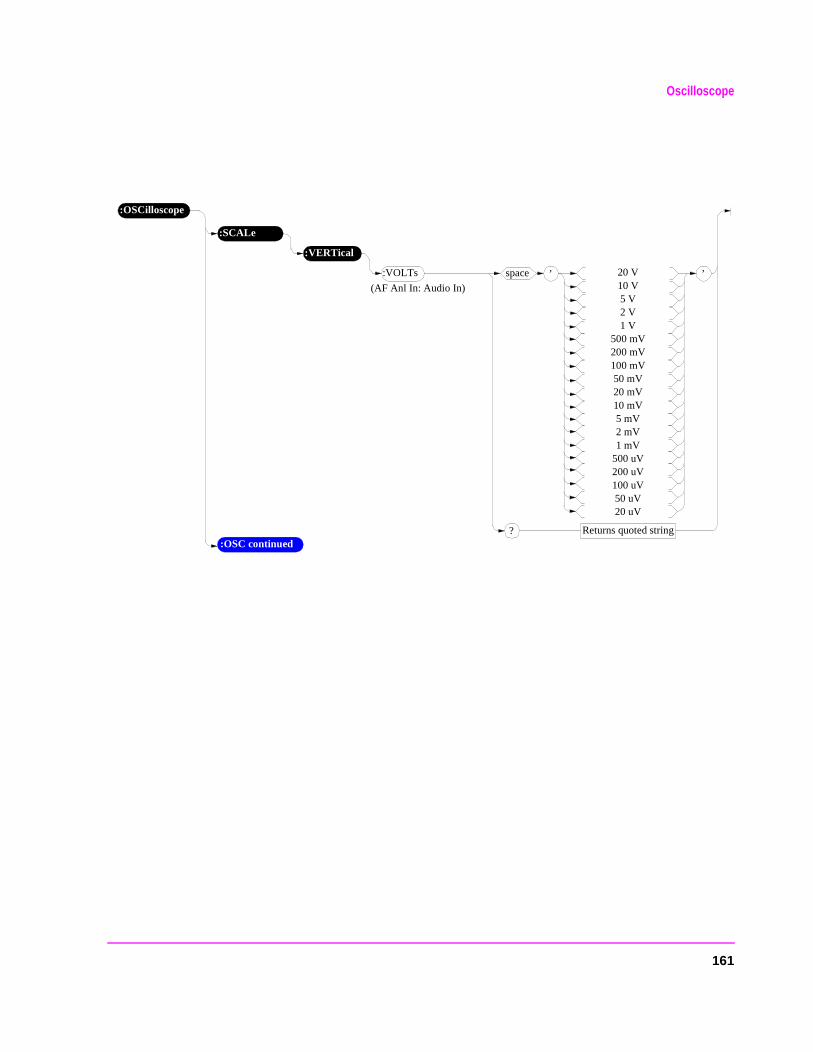
Oscilloscope
:OSCilloscope
’space 20 V10 V5 V2 V1 V
500 mV200 mV100 mV50 mV20 mV10 mV5 mV2 mV1 mV
500 uV200 uV100 uV50 uV20 uV
Returns quoted string?
’
:SCALe
:VERTical
:VOLTs
(AF Anl In: Audio In)
:OSC continued
161
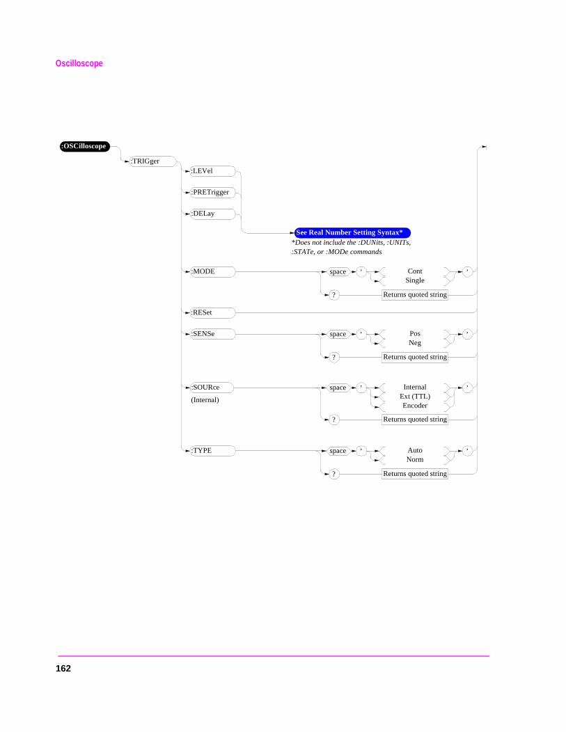
Oscilloscope
:OSCilloscope
:LEVel:TRIGger
:PRETrigger
See Real Number Setting Syntax**Does not include the :DUNits, :UNITs, :STATe, or :MODe commands
:DELay
’space InternalExt (TTL)Encoder
Returns quoted string?
’:SOURce
’space ContSingle
Returns quoted string?
’:MODE
’space PosNeg
Returns quoted string?
’:SENSe
’space AutoNorm
Returns quoted string?
’:TYPE
:RESet
(Internal)
162
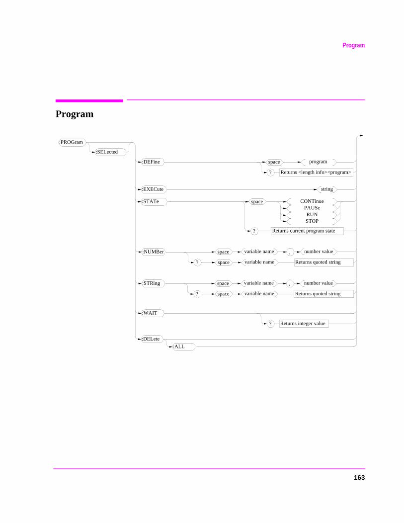
163
Program
Program
:PROGram
:SELected
:ALL
:DELete
:DEFine space program
Returns <length info><program>?
:EXECute string
space CONTinuePAUSeRUNSTOP
Returns current program state?
:STATe
:STRing ,space number value
Returns quoted string?
variable name
space variable name
:WAIT
Returns integer value?
:NUMBer ,space number value
Returns quoted string?
variable name
space variable name
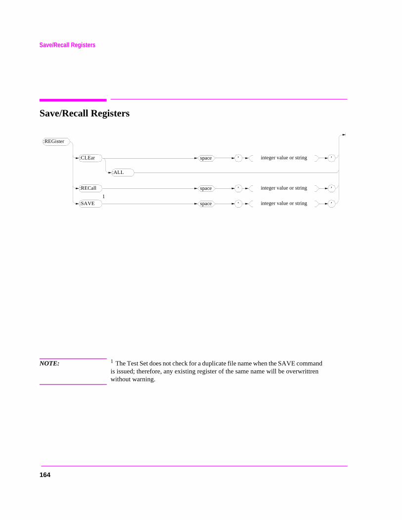
164
Save/Recall Registers
Save/Recall Registers
NOTE: 1 The Test Set does not check for a duplicate file name when the SAVE command is issued; therefore, any existing register of the same name will be overwrittren without warning.
:REGister
:ALL
:CLEar ’space integer value or string ’
:RECall ’space integer value or string ’
:SAVE ’space integer value or string ’
1
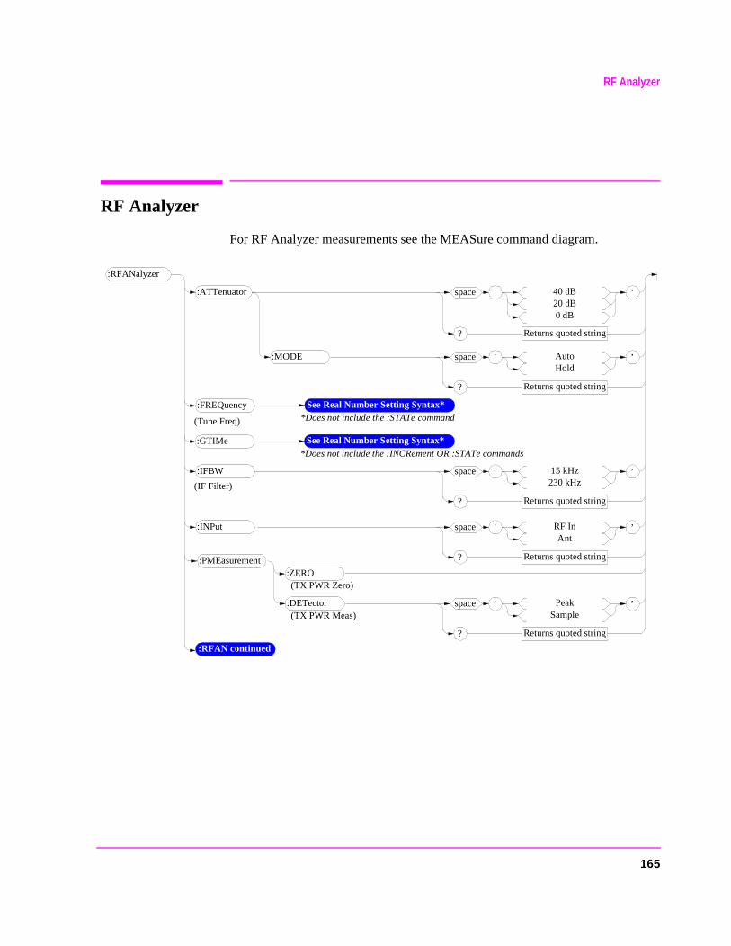
RF Analyzer
RF Analyzer
For RF Analyzer measurements see the MEASure command diagram.
:RFANalyzer
:RFAN continued
:ZERO:PMEasurement
’space 40 dB20 dB0 dB
Returns quoted string?
’:ATTenuator
(TX PWR Zero)
’space AutoHold
Returns quoted string?
’:MODE
See Real Number Setting Syntax**Does not include the :STATe command
:FREQuency
See Real Number Setting Syntax**Does not include the :INCRement OR :STATe commands
:GTIMe
(Tune Freq)
(IF Filter)
’space 15 kHz230 kHz
Returns quoted string?
’:IFBW
’space PeakSample
Returns quoted string?
’:DETector
’space RF InAnt
Returns quoted string?
’:INPut
(TX PWR Meas)
165
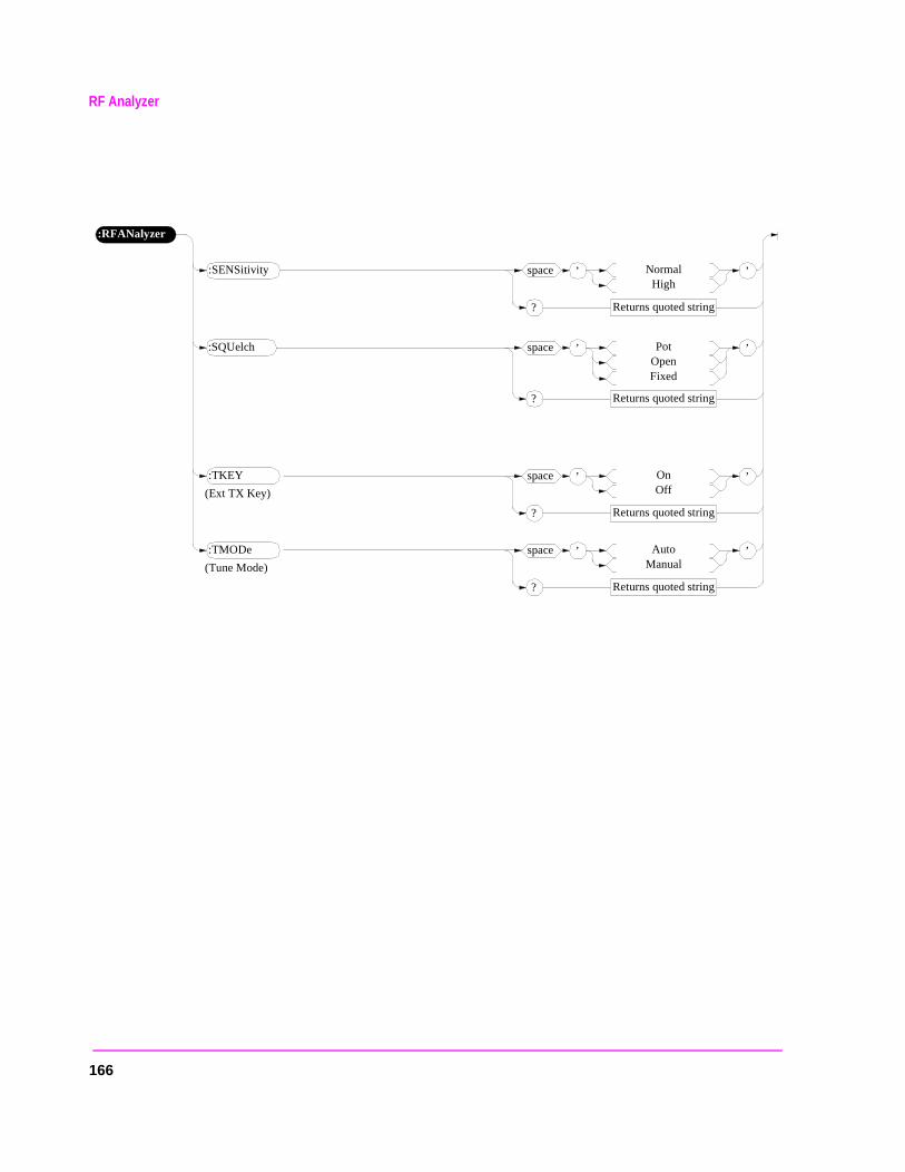
RF Analyzer
:RFANalyzer
(Tune Mode)
’space NormalHigh
Returns quoted string?
’:SENSitivity
’space OnOff
Returns quoted string?
’:TKEY
’space AutoManual
Returns quoted string?
’:TMODe
’space PotOpenFixed
Returns quoted string?
’:SQUelch
(Ext TX Key)
166
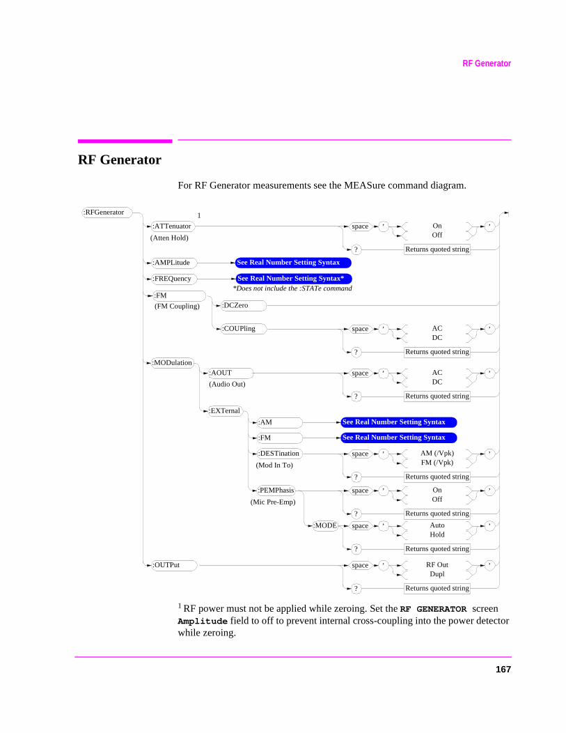
167
RF Generator
RF Generator
For RF Generator measurements see the MEASure command diagram.
1 RF power must not be applied while zeroing. Set the RF GENERATOR screen Amplitude field to off to prevent internal cross-coupling into the power detector while zeroing.
:RFGenerator
:DCZero:FM
:ATTenuator ’space OnOff
Returns quoted string?
’
See Real Number Setting Syntax**Does not include the :STATe command
:FREQuency
(Mod In To)
’space AM (/Vpk)FM (/Vpk)
Returns quoted string?
’:DESTination
’space ACDC
Returns quoted string?
’:COUPling
’space RF OutDupl
Returns quoted string?
’:OUTPut
(FM Coupling)
(Atten Hold)
:AMPLitude See Real Number Setting Syntax
1
:MODulation
’space ACDC
Returns quoted string?
’:AOUT
(Audio Out)
:EXTernal
:AM See Real Number Setting Syntax
:FM See Real Number Setting Syntax
(Mic Pre-Emp)
’space OnOff
Returns quoted string?
’:PEMPhasis
’space AutoHold
Returns quoted string?
’:MODE
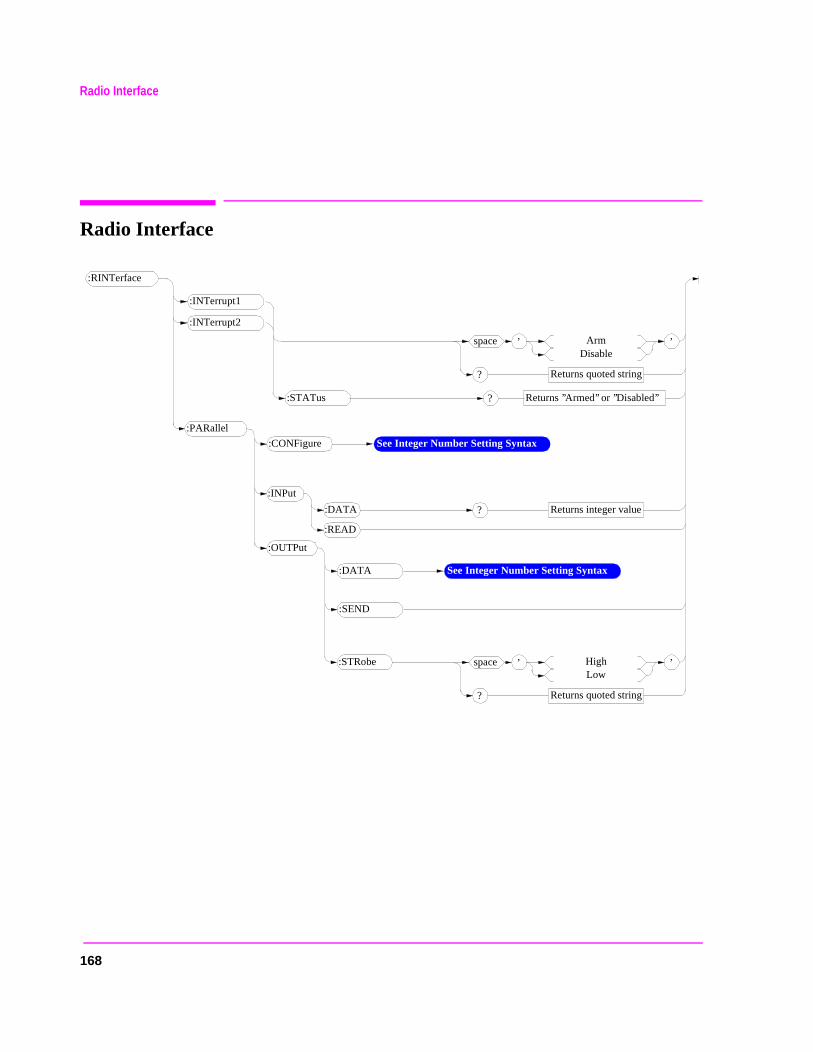
168
Radio Interface
Radio Interface
:RINTerface
:STATus
:INTerrupt2
:SEND
’space ArmDisable
Returns quoted string?
’
:PARallel
Returns integer value?
:INPut
:OUTPut
’space HighLow
Returns quoted string?
’:STRobe
:INTerrupt1
Returns ’’Armed’’ or ’’Disabled’’?
:DATA
:READ
:DATA See Integer Number Setting Syntax
:CONFigure See Integer Number Setting Syntax
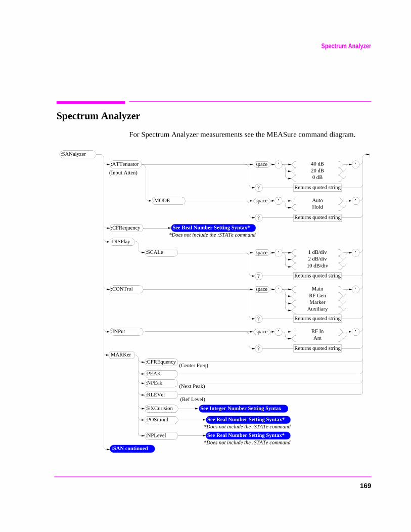
Spectrum Analyzer
Spectrum Analyzer
For Spectrum Analyzer measurements see the MEASure command diagram.
:SANalyzer
:SAN continued
:CFREquency:MARKer
’space 40 dB20 dB0 dB
Returns quoted string?
’:ATTenuator
(Center Freq)
’space AutoHold
Returns quoted string?
’:MODE
See Real Number Setting Syntax**Does not include the :STATe command
:CFRequency
’space RF InAnt
Returns quoted string?
’:INPut
(Input Atten)
’space 1 dB/div2 dB/div
10 dB/div
Returns quoted string?
’
:DISPlay
:SCALe
’space MainRF GenMarker
Auxiliary
Returns quoted string?
’:CONTrol
:PEAK
:NPEak
:RLEVel
(Next Peak)
(Ref Level)
See Real Number Setting Syntax**Does not include the :STATe command
:NPLevel
:EXCurision See Integer Number Setting Syntax
See Real Number Setting Syntax**Does not include the :STATe command
:POSitionl
169
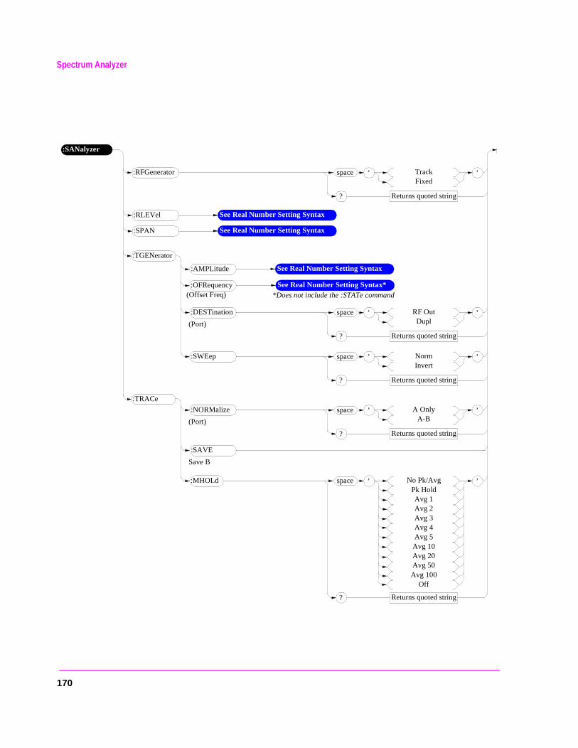
Spectrum Analyzer
:SANalyzer
’space TrackFixed
Returns quoted string?
’:RFGenerator
:RLEVel See Real Number Setting Syntax
:SPAN See Real Number Setting Syntax
(Port)
’space RF OutDupl
Returns quoted string?
’:DESTination
:TGENerator
:AMPLitude See Real Number Setting Syntax
See Real Number Setting Syntax**Does not include the :STATe command
:OFRequency(Offset Freq)
’space NormInvert
Returns quoted string?
’:SWEep
(Port)
’space A OnlyA-B
Returns quoted string?
’:NORMalize
:TRACe
Save B
:SAVE
’space No Pk/AvgPk HoldAvg 1Avg 2Avg 3Avg 4Avg 5
Avg 10Avg 20Avg 50Avg 100
Off
Returns quoted string?
’:MHOLd
170
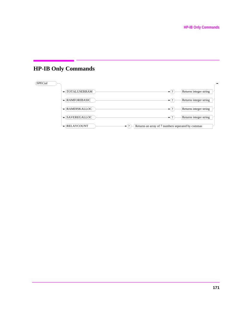
171
HP-IB Only Commands
HP-IB Only Commands
:SPECial
:TOTALUSERRAM Returns integer string?
:RAMFORIBASIC Returns integer string?
:RAMDISKALLOC Returns integer string?
:SAVEREGALLOC Returns integer string?
:RELAYCOUNT ? Returns an array of 7 numbers seperated by commas
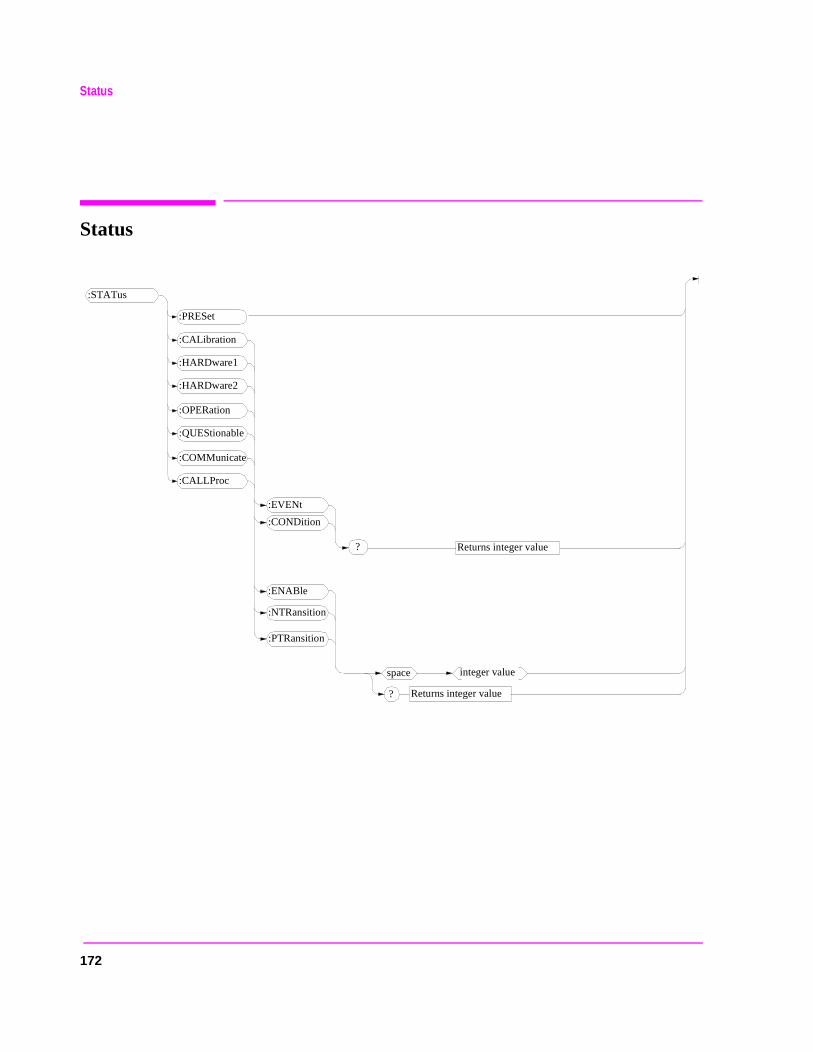
172
Status
Status
:STATus
:PRESet
:EVENt
? Returns integer value
:CONDition
:ENABle
:NTRansition
:PTRansition
:CALibration
:HARDware1
:HARDware2
:OPERation
:QUEStionable
:COMMunicate
:CALLProc
space integer value
Returns integer value?
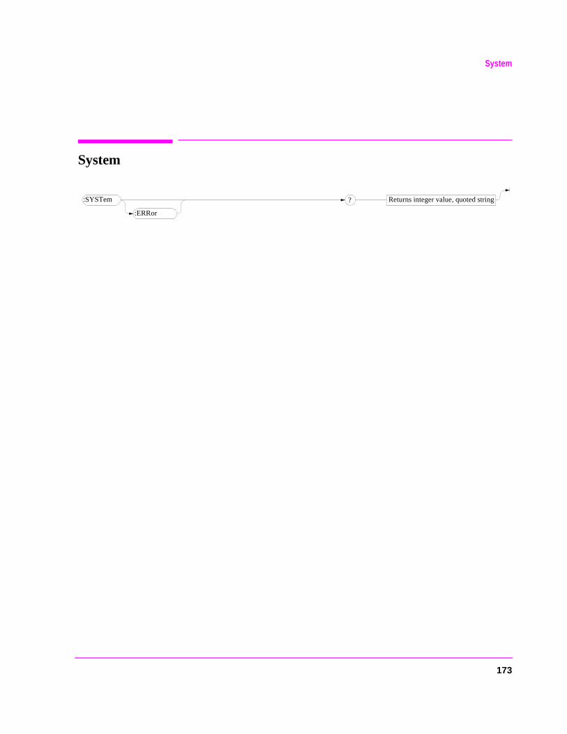
173
System
System
:SYSTem
:ERRor
Returns integer value, quoted string?

Tests
Tests
:TESTs
:CONFigure
,
space
integer value
Returns unquoted string, 5 elements seperated by commas?
integer value
space integer value
:COMMent1
:COMMent2
’space
Returns quoted string?
’
(Comment for new procedure)
(Comment for new procedure)
, ’ string ’ , ’ string ’ ,
, ’ string ’
(External Devices)
:EXECution
(Port B) ’space CrtPrinter
Returns quoted string?
’:DESTination
’space ContinueStop
Returns quoted string?
’:FAILure
’space AllFailures
Returns quoted string?
’:RESults
’space ContinuousSingle Step
Returns quoted string?
’:RUN
:TEST continued
:HEADing1
:HEADing2
’space string
Returns quoted string?
’
174
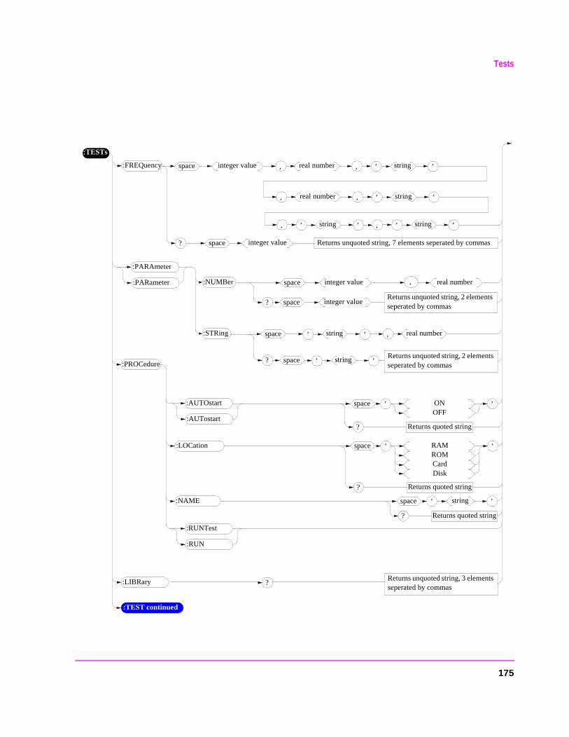
Tests
Returns unquoted string, 2 elements seperated by commas
:TESTs
:FREQuency space
Returns unquoted string, 7 elements seperated by commas?
integer value
space integer value
, real number , ’ string ’
:PROCedure
’space ONOFF
Returns quoted string?
’
:TEST continued
, ’ string ’ , ’ string ’
, real number , ’ string ’
:AUTOstart
:AUTostart
:RUNTest
:RUN
’space RAMROMCardDisk
Returns quoted string?
’:LOCation
:NAME ’space string
Returns quoted string?
’
:NUMBer space integer value
?
:PARAmeter
:PARameter , real number
space integer value
Returns unquoted string, 2 elements seperated by commas
:STRing space
? space
, real number’ string ’
’ string ’
:LIBRary Returns unquoted string, 3 elements seperated by commas
?
175
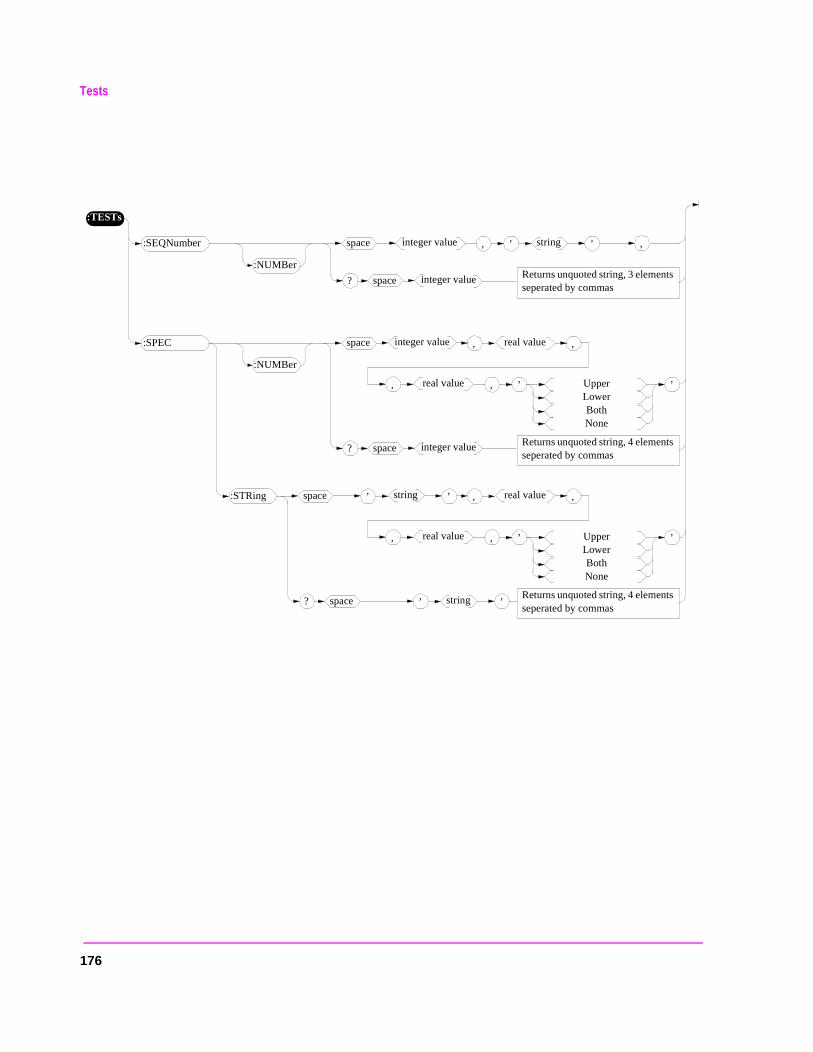
Tests
:TESTs
’ UpperLowerBothNone
’
:NUMBer
:SEQNumber
Returns unquoted string, 3 elements seperated by commas
space
? space
,’ string ’integer value ,
integer value
:NUMBer
:SPEC
Returns unquoted string, 4 elements seperated by commas
space
? space
integer value ,
integer value
real value ,
, real value ,
’ UpperLowerBothNone
’
:STRing
Returns unquoted string, 4 elements seperated by commas
space
? space
, real value ,
, real value ,
’ string ’
’ string ’
176
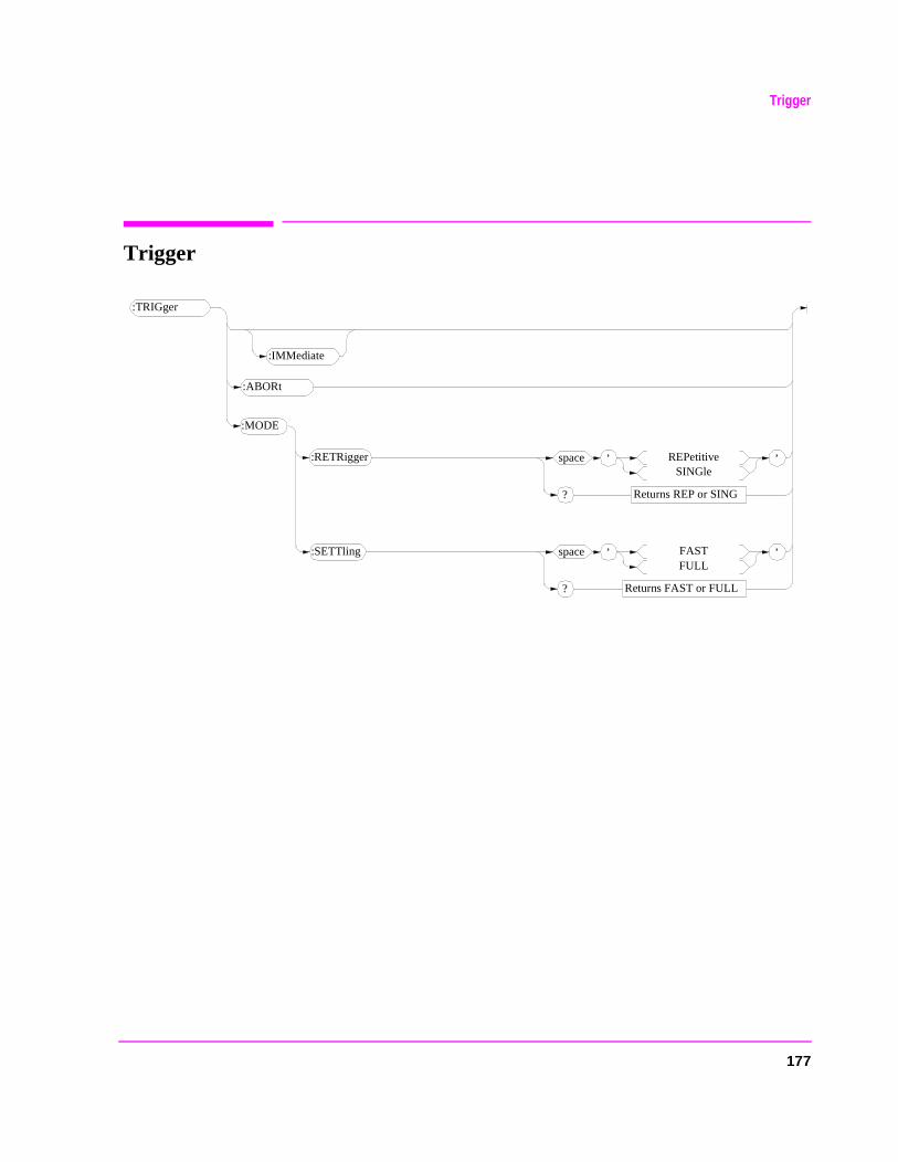
177
Trigger
Trigger
:TRIGger
:RETRigger
:MODE
:IMMediate
’space FASTFULL
Returns FAST or FULL?
’:SETTling
’space REPetitiveSINGle
Returns REP or SING?
’
:ABORt
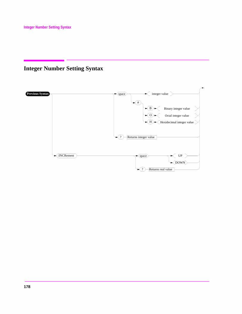
178
Integer Number Setting Syntax
Integer Number Setting Syntax
:INCRement
Previous Syntax
? Returns integer value
space integer value
? Returns real value
space UP
DOWN
#
B Binary integer value
O Octal integer value
H Hexidecimal integer value
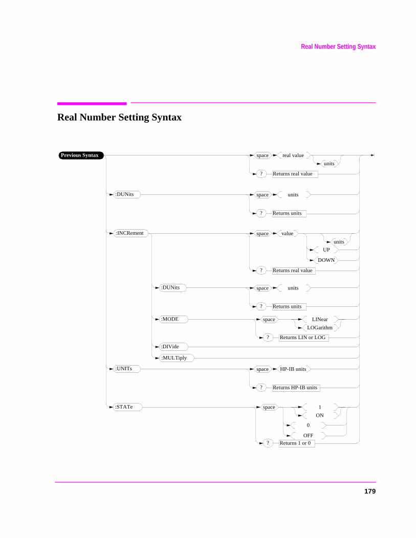
179
Real Number Setting Syntax
Real Number Setting Syntax
:INCRement
:DUNits
:MODE
? Returns LIN or LOG
space LINear
LOGarithm
Previous Syntax
? Returns real value
space real value
units
? Returns units
space units
? Returns real value
space value
units
:DUNits
? Returns units
space units
:DIVide
:MULTiply
:UNITs
? Returns HP-IB units
space HP-IB units
:STATe
? Returns 1 or 0
space 1
ON
0
OFF
UP
DOWN
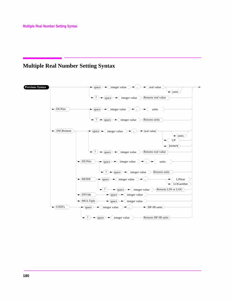
180
Multiple Real Number Setting Syntax
Multiple Real Number Setting Syntax
:INCRement
:DUNits
:MODE
? Returns LIN or LOG
space LINear
LOGarithm
Previous Syntax
? Returns real value
space real value
units
? Returns units
space units
? Returns real value
space real value
units
:DUNits
? Returns units
space units
:DIVide
:MULTiply
:UNITs
? Returns HP-IB units
space HP-IB units
UP
DOWN
integer value ,
space integer value
integer value ,
space integer value
integer value ,
space integer value
integer value ,
space integer value
integer value ,
space integer value
space integer value
space integer value
integer value ,
space integer value
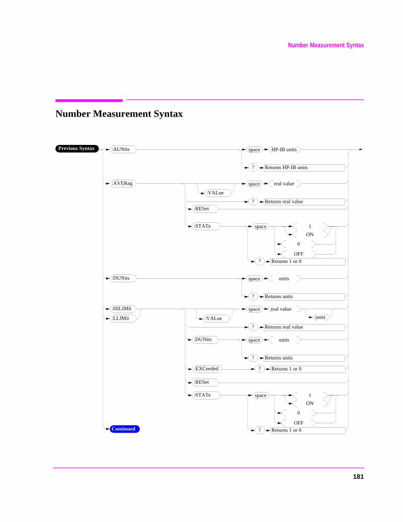
Number Measurement Syntax
Number Measurement Syntax
:DUNits
? Returns HP-IB units
space HP-IB units
? Returns units
space units
:STATe
? Returns 1 or 0
space 1
ON
0
OFF
:AUNits
:AVERag
? Returns real value
space real value
:VALue
:RESet
:STATe
? Returns 1 or 0
space 1
ON
0
OFF
:HILIMit
? Returns real value
space real value
:RESet
:LLIMit
:DUNits
? Returns units
space units
:EXCeeded ? Returns 1 or 0
Continued
units:VALue
Previous Syntax
181
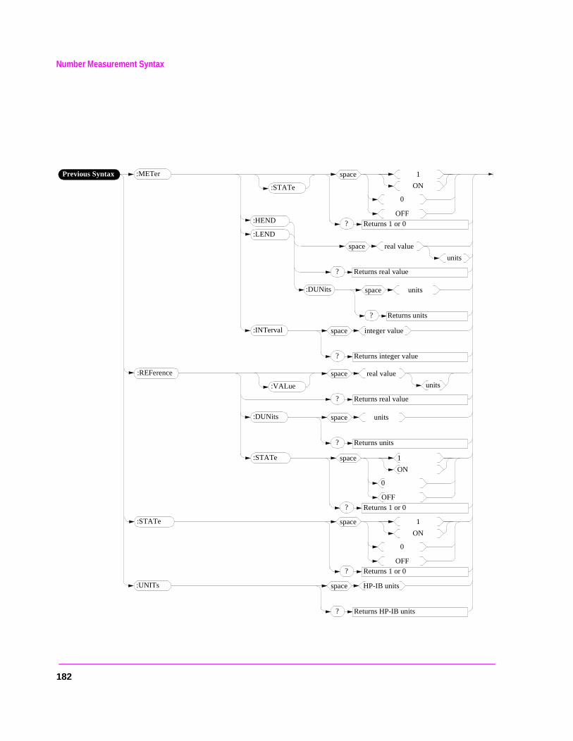
Number Measurement Syntax
Previous Syntax
:UNITs
? Returns HP-IB units
space HP-IB units
? Returns 1 or 0
space 1
ON
0
OFF
:METer
:STATe
? Returns 1 or 0
space 1
ON
0
OFF
:REFerence
? Returns real value
space real value
:DUNits
? Returns units
space units
units
:HEND
? Returns real value
space real value
:LEND
:DUNits
? Returns units
space units
units
:INTerval
? Returns integer value
space integer value
:STATe
? Returns 1 or 0
space 1
ON
0
OFF
:VALue
:STATe
182
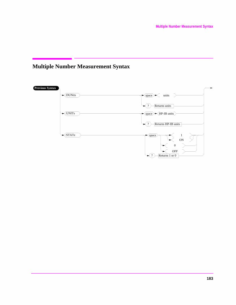
183
Multiple Number Measurement Syntax
Multiple Number Measurement Syntax
:DUNits
Previous Syntax
? Returns units
space units
:UNITs
? Returns HP-IB units
space HP-IB units
:STATe
? Returns 1 or 0
space 1
ON
0
OFF
Equivalent Front-Panel Key Commands
Equivalent Front-Panel Key Commands
Most front-panel keys have an equivalent HP-IB command for remote use. The various key functions are explained in more detail in the User’s Guide.
All command examples are in BASIC.
SHIFT key, CANCEL key, CURSOR CONTROL knob
These functions are not required for HP-IB use, and have no equivalent HP-IB commands.
DATA Keys
In addition to the numeric keys, the DATA keys contain the units-of-measure keys, and the ON/OFF, YES, NO, and ENTER keys. Setting units-of-measure through HP-IB is described in "Specifying Units-of-Measure for Settings and Measurement Results" on page 77. The ON/OFF function is described in "Using the STATe Command" on page 90. The YES, NO, and ENTER keys are not required for HP-IB use, and have no equivalent HP-IB commands.
184
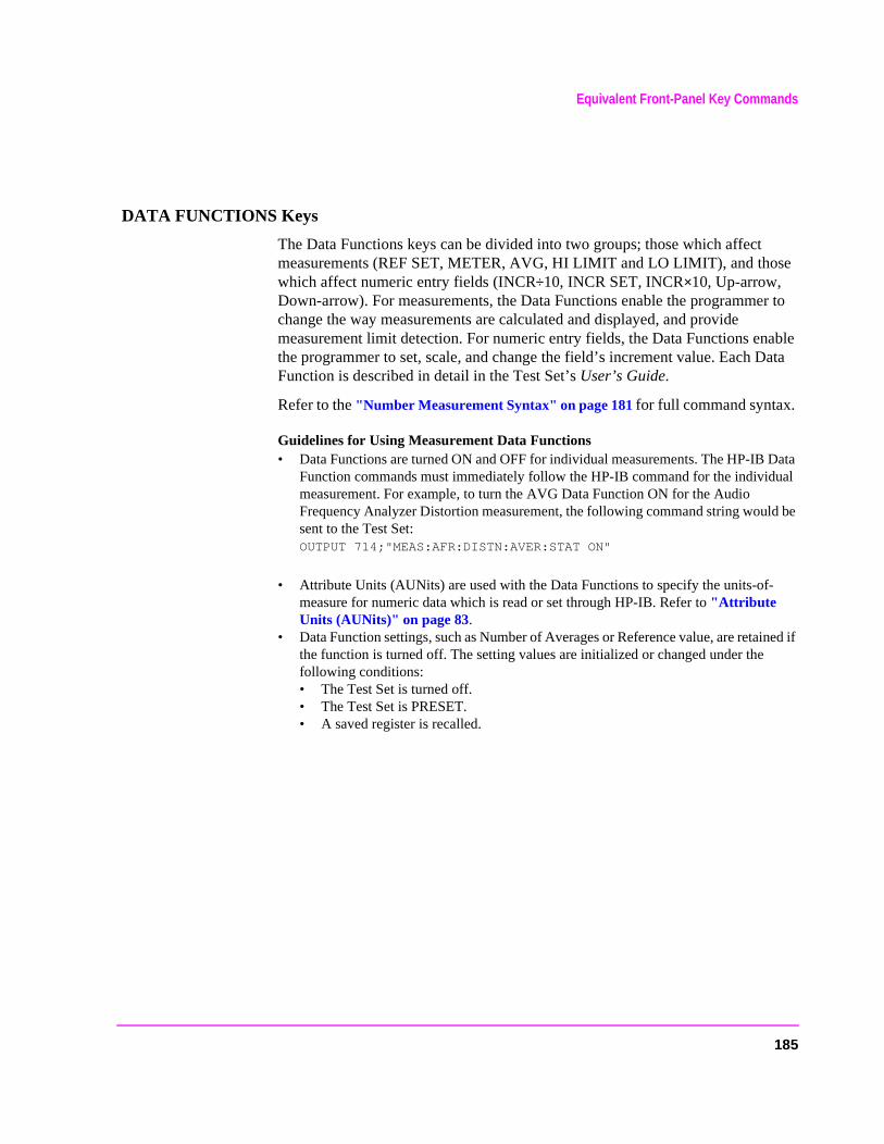
Equivalent Front-Panel Key Commands
ata
Data al
d be
ined if
DATA FUNCTIONS Keys
The Data Functions keys can be divided into two groups; those which affect measurements (REF SET, METER, AVG, HI LIMIT and LO LIMIT), and those which affect numeric entry fields (INCR÷10, INCR SET, INCR×10, Up-arrow, Down-arrow). For measurements, the Data Functions enable the programmer to change the way measurements are calculated and displayed, and provide measurement limit detection. For numeric entry fields, the Data Functions enable the programmer to set, scale, and change the field’s increment value. Each DFunction is described in detail in the Test Set’s User’s Guide.
Refer to the "Number Measurement Syntax" on page 181 for full command syntax.
Guidelines for Using Measurement Data Functions • Data Functions are turned ON and OFF for individual measurements. The HP-IB
Function commands must immediately follow the HP-IB command for the individumeasurement. For example, to turn the AVG Data Function ON for the Audio Frequency Analyzer Distortion measurement, the following command string woulsent to the Test Set: OUTPUT 714;"MEAS:AFR:DISTN:AVER:STAT ON"
• Attribute Units (AUNits) are used with the Data Functions to specify the units-of-measure for numeric data which is read or set through HP-IB. Refer to "Attribute Units (AUNits)" on page 83.
• Data Function settings, such as Number of Averages or Reference value, are retathe function is turned off. The setting values are initialized or changed under the following conditions: • The Test Set is turned off. • The Test Set is PRESET. • A saved register is recalled.
185
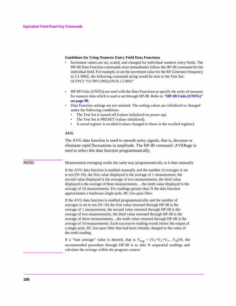
Equivalent Front-Panel Key Commands
. The the ency
sure
ged
Guidelines for Using Numeric Entry Field Data Functions • Increment values are set, scaled, and changed for individual numeric entry fields
HP-IB Data Function commands must immediately follow the HP-IB command forindividual field. For example, to set the increment value for the RF Generator frequto 2.5 MHZ, the following command string would be sent to the Test Set: OUTPUT 714;"RFG:FREQ:INCR 2.5 MHZ"
• HP-IB Units (UNITs) are used with the Data Functions to specify the units-of-meafor numeric data which is read or set through HP-IB. Refer to "HP-IB Units (UNITs)" on page 80.
• Data Function settings are not retained. The setting values are initialized or chanunder the following conditions: • The Test Set is turned off (values initialized on power up). • The Test Set is PRESET (values initialized). • A saved register is recalled (values changed to those in the recalled register).
AVG
The AVG data function is used to smooth noisy signals, that is, decrease or eliminate rapid fluctuations in amplitude. The HP-IB command :AVERage is used to select this data function programmatically.
NOTE: Measurement averaging works the same way programmatically as it does manually
If the AVG data function is enabled manually and the number of averages is set to ten (N=10), the first value displayed is the average of 1 measurement, the second value displayed is the average of two measurements, the third value displayed is the average of three measurements… the tenth value displayed is the average of 10 measurements. For readings greater than N the data function approximates a hardware single-pole, RC low-pass filter.
If the AVG data function is enabled programmatically and the number of averages is set to ten (N=10) the first value returned through HP-IB is the average of 1 measurement, the second value returned through HP-IB is the average of two measurements, the third value returned through HP-IB is the average of three measurements…the tenth value returned through HP-IB is the average of 10 measurements. Each successive reading would mimic the output of a single-pole, RC low-pass filter that had been initially charged to the value of the tenth reading.
If a “true average” value is desired, that is Vavg = (V1+V2+V3…VN)/N, therecommended procedure through HP-IB is to take N sequential readings andcalculate the average within the program context
186
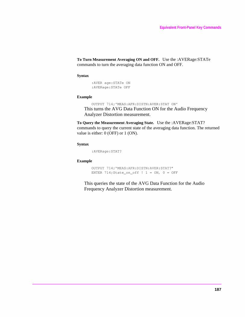
Equivalent Front-Panel Key Commands
To Turn Measurement Averaging ON and OFF. Use the :AVERage:STATe commands to turn the averaging data function ON and OFF.
Syntax
:AVER age:STATe ON:AVERage:STATe OFF
Example
OUTPUT 714;"MEAS:AFR:DISTN:AVER:STAT ON"
This turns the AVG Data Function ON for the Audio Frequency Analyzer Distortion measurement.
To Query the Measurement Averaging State. Use the :AVERage:STAT? commands to query the current state of the averaging data function. The returned value is either: 0 (OFF) or 1 (ON).
Syntax
:AVERage:STAT?
Example
OUTPUT 714;"MEAS:AFR:DISTN:AVER:STAT?”ENTER 714;State_on_off ! 1 = ON, 0 = OFF
This queries the state of the AVG Data Function for the Audio Frequency Analyzer Distortion measurement.
187
Equivalent Front-Panel Key Commands
To Reset Averaging. Use the :AVERage:RESet commands to restart the averaging algorithm used to calculate an averaged measurement.
Syntax
:AVERage:RESet
Example
OUTPUT 714;"MEAS:AFR:DISTN:AVER:RES"
This resets the AVG Data Function for the Audio Frequency Analyzer Distortion measurement.
To Set the Number of Averages. Use the :AVERage:VALue commands to set the number of averages used by the averaging algorithm.
Syntax
:AVERage:VALue
Example
OUTPUT 714;"MEAS:AFR:DISTN:AVER:VAL 25"
This sets the number of averages to 25 for the AVG Data Function for the Audio Frequency Analyzer Distortion measurement.
To Query the Number of Averages. Use the :AVERage:VALue? commands to query the number of averages used by the averaging algorithm.
Syntax
:AVERage:VALue?
Example
OUTPUT 714;"MEAS:AFR:DISTN:AVER:VAL?"ENTER 714;Num_of_avgs
This queries the number of averages for the AVG Data Function for the Audio Frequency Analyzer Distortion measurement.
188
Equivalent Front-Panel Key Commands
e
HI LIMIT and LO LIMIT
The HI LIMIT and LO LIMIT Data Functions are used to define a measurement “window” which can be used to detect measured values which are outside thdefined limits. The HP-IB commands :HLIMit (high limit) and :LLIMit (low limit) are used to set these data functions programmatically.
To Turn High and Low Measurement Limit Checking ON and OFF. Use the :HLIMit:STATe and :LLIMit:STATe commands to turn high and low measurement limit checking ON and OFF.
Syntax
:HLIMit:STATe ON:HLIMit:STATe OFF:LLIMit:STATe ON:LLIMit:STATe OFF
Example
OUTPUT 714;"MEAS:AFR:DISTN:HLIM:STAT ON"OUTPUT 714;"MEAS:AFR:DISTN:LLIM:STAT ON"
This turns high and low measurement limit checking ON for the Audio Frequency Analyzer Distortion measurement.
189
Equivalent Front-Panel Key Commands
To Query the State of High and Low Measurement Limit Checking. Use the :HLIMit:STATe? and :LLIMit:STATe? commands to query the current state of the high and low measurement limit checking. The returned value is either: 0 (OFF) or 1 (ON).
Syntax
:HLIMit:STATe?:LLIMit:STATe?
Example
OUTPUT 714;"MEAS:AFR:DISTN:LLIM:STAT?"ENTER 714;Lo_state ! 1 = ON, 0 = OFF OUTPUT 714;"MEAS:AFR:DISTN:HLIM:STAT?"ENTER 714;Hi_state ! 1 = ON, 0 = OFF
This queries the state of high and low measurement limit checking for the Audio Frequency Analyzer Distortion measurement.
To Set High and Low Measurement Limits. Use the :HLIMit:VALue and :LLIMit:VALue commands to set the high and low measurement limit values.
Syntax
:HLIMit:VALue:LLIMit:VALue
Example
OUTPUT 714;"MEAS:AFR:FM:HLIM 7.5 KHZ"OUTPUT 714;"MEAS:AFR:FM:LLIM 2.5 KHZ"
This sets a high measurement limit of 7.5 kHz and a low measurement limit of2.5 kHz for the Audio Frequency Analyzer FM Deviation measurement.
NOTE: When setting high and low limit values, a non–Attribute Unit unit-of-measure must be specified in the command string, otherwise the current Attribute Unit is assumed by the Test Set. Refer to "Attribute Units (AUNits)" on page 83.
190
Equivalent Front-Panel Key Commands
To Set the Display Units for High and Low Measurement Limits. Use the :HLIMit:DUNits and :LLIMit:DUNits commands to set the units-of-measure used to display the high and low measurement limit values. Refer to "Display Units (DUNits)" on page 77 for description of Display Units.
Syntax
:HLIMit:DUNits <disp_units>:LLIMit:DUNits <disp_units>
Example
OUTPUT 714;"MEAS:AFR:FM:HLIM:DUN KHZ"OUTPUT 714;"MEAS:AFR:FM:LLIM:DUN KHZ"
This sets the high and low measurement limit Display Units to kHz for the Audio Frequency Analyzer FM Deviation measurement.
NOTE: When querying measurement limits through HP-IB, the Test Set always returns numeric values in Attribute Units, regardless of the current Display Units or HP-IB Units settings. Numeric values are expressed in scientific notation. Refer to "Attribute Units (AUNits)" on page 83.
To Query the Display Units for High and Low Measurement Limits. Use the :HLIMit:DUNits? and :LLIMit:DUNits? commands to query the units-of-measure used to display the high and low measurement limit values. Refer to "Display Units (DUNits)" on page 77 for description of Display Units.
Syntax
:HLIMit:DUNits?:LLIMit:DUNits?
Example
OUTPUT 714;"MEAS:AFR:FM:HLIM:DUN?"ENTER 714;Hi_disp_unit$OUTPUT 714;"MEAS:AFR:FM:LLIM:DUN?"ENTER 714;Lo_disp_unit$
This queries the high measurement limit Display Units for the Audio Frequency Analyzer FM Deviation measurement.
NOTE: When querying measurement limits through HP-IB, the Test Set always returns numeric values in Attribute Units, regardless of the current Display Units or HP-IB Units settings. Numeric values are expressed in scientific notation. Refer to "Attribute Units (AUNits)" on page 83.
191
Equivalent Front-Panel Key Commands
To Query the High and Low Measurement Limit Settings. Use the :HLIMit:VALue? and :LLIMit:VALue? commands to query the high and low measurement limit settings.
Syntax
:HLIMit:VALue?:LLIMit:VALue?
Example
OUTPUT 714;"MEAS:AFR:FM:HLIM:VAL?"ENTER 714;High_limitOUTPUT 714;"MEAS:AFR:FM:LLIM:VAL?"ENTER 714;Low_limit
This queries the high and low measurement limits for the Audio Frequency Analyzer FM Deviation measurement.
NOTE: When querying measurement limits through HP-IB, the Test Set always returns numeric values in Attribute Units, regardless of the current Display Units or HP-IB Units settings. Numeric values are expressed in scientific notation. Refer to "Attribute Units (AUNits)" on page 83.
To Detect If a Measurement Limit Has Been Exceeded. Use the :HLIMit:EXCeeded? and :LLIMit:EXCeeded? commands to detect if a measurement limit has been exceeded. The returned value is either: 0 (NO) or 1 (YES).
Syntax
:HLIMit:EXCeeded?:LLIMit:EXCeeded?
Example
ENTER 714;Hi_limit_exced ! 1= YES, 0 = NOOUTPUT 714;"MEAS:AFR:FM:LLIM:EXC?"ENTER 714;Lo_limit_exced ! 1= YES, 0 = NO OUTPUT 714;"MEAS:AFR:FM:HLIM:EXC?"
This determines if the high or low measurement limits for the Audio Frequency Analyzer FM Deviation measurement have been exceeded.
192
Equivalent Front-Panel Key Commands
To Reset Measurement Limit Detection. Use the :HLIMit:RESet and :LLIMit:RESet commands to reset measurement limit detection. Once a high or low measurement limit has been exceeded (:HLIMit:EXCeeded? returns a 1 or :LLIMit:EXCeeded? returns a 1), measurement limit detection is disabled until reset by the :RESet command.
Syntax
:HLIMit:RESet :LLIMit:RESet
Example
OUTPUT 714;"MEAS:AFR:FM:HLIOUTPUT 714;"MEAS:AFR:FM:LLIM:RES"
This resets high and low measurement limit detection for the Audio Frequency Analyzer FM Deviation measurement.
INCR SET
The Increment Set Data Function sets the increment value for real-number numeric entry fields. The HP-IB command :INCRement is used to select this data function programmatically.
To Set the Increment Value. Use the :INCRement command to set the increment value.
Syntax
:INCRement
Example
OUTPUT 714;"RFG:FREQ:INCR 2.5 MHZ"
This sets the increment value for the RF Gen Freq field to 2.5 MHz.
NOTE: When setting the value of a numeric field (such as RF Gen Freq), any non–HP-IB Unit unit-of-measure must be specified in the command string, otherwise the current HP-IB Unit is assumed by the Test Set. Integer-only fields (such as Intensity and Print Adrs) have a fixed increment of 1and cannot be changed.
193
Equivalent Front-Panel Key Commands
To Query the Increment Value. Use the :INCRement? command to query the increment value.
Syntax
:INCRement?
Example
OUTPUT 714;"RFG:FREQ:INCR?"ENTER 714;Incr_value
This queries the increment value for the RF Gen Freq field.
NOTE: When querying a field setting or measurement result through HP-IB, the Test Set always returns numeric values in HP-IB Units or Attribute Units, regardless of the field’s current Display Units setting. Refer to "Attribute Units (AUNits)" on page 83 and "HP-IB Units (UNITs)" on page 80.
To Set the Increment Mode. Use the :INCRement:MODE commands to set the increment mode to linear or logarithmic.
Syntax
:INCRement:MODE <LOGarithm or LINear>
Example
OUTPUT 714;"RFG:FREQ:INCR:MODE LOG"
This sets the increment mode for the RF Generator’s frequency to logarithmic.
To Query the Increment Mode. Use the :INCRement:MODE? commands to query the increment mode.
Syntax
:INCRement:MODE?
Example
ENTER 714;Mode$ ! returns LIN or LOGOUTPUT 714;"RFG:FREQ:INCR:MODE?"
This queries the increment mode of the RF Generator’s frequency.
194
Equivalent Front-Panel Key Commands
or’s
To Set the Increment Value Display Units. Use the :INCRement:DUNits commands to set the units-of-measure used to display the increment value. Refer to "Display Units (DUNits)" on page 77 for description of Display Units.
Syntax
:INCRement:DUNits <disp_units>
Example
OUTPUT 714;"RFG:FREQ:INCR:DUN KHZ"
This sets the increment value’s Display Units to kHz for the RF Generator’s frequency.
NOTE: When querying a field setting through HP-IB, the Test Set always returns numeric values in HP-IB Units or Attribute Units, regardless of the field’s current Display Units setting. Numeric values are expressed in scientific notation. Refer to "Attribute Units (AUNits)" on page 83 and "HP-IB Units (UNITs)" on page 80.
To Query the Increment Value Display Units. Use the :INCRement:DUNits? commands to query the units-of-measure used to display the increment value. Refer to "Display Units (DUNits)" on page 77 for description of Display Units.
Syntax
:INCRement:DUNits?
Example
OUTPUT 714;"RFG:FREQ:INCR:DUN?"ENTER 714;Disp_unit$
This queries the increment value’s Display Units for the RF Generatfrequency.
INCR×10
The INCR×10 Data Function increases the increment setting by a factor of 10 (new increment setting = current increment setting × 10).
NOTE: Integer-only fields (such as Intensity and Print Adrs) have a fixed increment of 1, and cannot be changed.
195

Equivalent Front-Panel Key Commands
d
ing the
ue.
Syntax
:INCRement:MULTiply
Example
OUTPUT 714;"RFG:FREQ:INCR:MULT"
If the RF Generator’s frequency increment is 1 MHz, this commandincreases increment value from 1 MHz to 10 MHz.
INCR÷10
The INCR÷10 Data Function reduces the increment setting by a factor of 10 (new increment setting = current increment setting ÷ 10).
NOTE: Integer-only fields (such as Intensity and Print Adrs) have a fixed increment of 1, and cannot be changed.
Syntax
:INCRement:DIVide
Example
OUTPUT 714;"RFG:FREQ:INCR:DIV"
If the RF Generator’s frequency increment is 10 MHz, this commanreduces the increment value from 10 MHz to 1 MHz.
Increment Up/Down (Arrow Keys)
The Increment Up/Down (Arrow Keys) Data Functions change the field’s settby one increment value (up or down). The increment value is determined by INCR SET (:INCRement) Data Function.
Syntax
:INCRement <UP or DOWN>
Example
OUTPUT 714;"RFG:FREQ:INCR UP"
This increases the RF Generator’s frequency by one increment val
196
Equivalent Front-Panel Key Commands
METER
The METER Data Function enables/disables the analog bar-graph meter for certain measurements. The HP-IB command :METer is used to select this data function programmatically.
To Turn the Meter ON and OFF. Use the :METer:STATe commands to turn the meter ON and OFF. The parameter can be a 1 or ON to turn the meter on and a 0 or OFF to turn the meter off.
Syntax
:METer:STATe <ON> or <1>:METer:STATe <OFF> or <0>
Example
OUTPUT 714;"MEAS:RFR:POW:MET ON"
This turns the analog bar-graph meter ON for the TX Power measurement.
To Query the State of the Meter. Use the :METer:STATe? commands to query the state of the analog bar-graph meter. The query returns a 1 if the meter is ON, and a 0 if the meter is OFF.
Syntax
:METer:STATe?
Example
OUTPUT 714;"MEAS:RFR:POW:MET:STAT?"ENTER 714;Meter_on_off ! returns a 1 (ON) or 0 (OFF)
This queries the state of the analog bar-graph meter for the TX Power measurement.
197

Equivalent Front-Panel Key Commands
To Set the Number of Intervals on the Meter. Use the :METer:INTerval commands to set the number of intervals displayed on the analog bar-graph meter.
Syntax
:METer:INTerval <integer valve>
Example
OUTPUT 714;"MEAS:RFR:POW:MET:INT 5"
This sets the number of intervals displayed on the analog bar-graph meter for the TX Power measurement.
To Query the Number of Intervals on the Meter. Use the :METer:INTerval? commands to query the number of intervals displayed on the analog bar-graph meter.
Syntax
:METer:INTerval?
Example
OUTPUT 714;MEAS:RFR:POW:MET:INT?ENTER 714;Num_intervals
This queries the number of intervals displayed on the analog bar-graph meter for the TX Power measurement.
198
Equivalent Front-Panel Key Commands
nd
d the
r-
To Set the Meter High End and Low End Points. Use the :METer:HEND and :MEter:LEND commands to set the analog bar-graph meter’s high endpoint alow endpoint.
Syntax
:METer:HEND <real number>:METer:LEND <real number>
Example
OUTPUT 714;"MEAS:RFR:POW:MET:HEND 20"OUTPUT 714;"MEAS:RFR:POW:MET:LEND 10"
This sets the analog bar-graph meter’s high endpoint to 20 watts anlow endpoint to 10 watts for the TX Power measurement.
When setting the value of the METER Data Function through HP-IB, a non-Attribute Unit unit-of-measure must be specified in the command string, otherwise the current Attribute Unit is assumed by the Test Set. Refer to "Attribute Units (AUNits)" on page 83.
To Query the Meter High End and Low End Points. Use the :METer:HEND? and :MEter:LEND? commands to query the analog bar-graph meter high endpoint and low endpoint.
Syntax
:METer:HEND?:METer:LEND?
Example
OUTPUT 714;"MEAS:RFR:POW:MET:HEND?"ENTER 714;Meter_hi_endOUTPUT 714;"MEAS:RFR:POW:MET:LEND?"ENTER 714;Meter_lo_end
This queries the high end point and low end point of the analog bagraph meter for the TX Power measurement.
NOTE: When querying the value of the METER Data Function through HP-IB, the Test Set always returns numeric values in Attribute Units, regardless of the current Display Units or HP-IB Units settings. Numeric values are expressed in scientific notation. Refer to "Attribute Units (AUNits)" on page 83.
199

Equivalent Front-Panel Key Commands
To Set the Meter High End and Low End Point Display Units. Use the :METer:HEND:DUNits and :MEter:LEND:DUNits commands to set the analog bar-graph meter high end point and low end point Display Units. Refer to "Display Units (DUNits)" on page 77 for description of Display Units.
Syntax
:METer:HEND:DUNits <disp_units> :METer:HEND:DUNits <disp_units>
Example
OUTPUT 714;"MEAS:RFR:POW:MET:HEND:DUN DBM"OUTPUT 714;"MEAS:RFR:POW:MET:LEND:DUN DBM"
This sets the high end point and low end point display units of the analog bar-graph meter for the TX Power measurement to DBM.
NOTE: When querying the METER Data Function through HP-IB, the Test Set always returns numeric values in Attribute Units, regardless of the current Display Units or HP-IB Units settings. Numeric values are expressed in scientific notation.
To Query the Meter High End and Low End Point Display Units. Use the :METer:HEND:DUNits? and :MEter:LEND:DUNits? commands to query the analog bar-graph meter high end point and low end point Display Units. Refer to "Display Units (DUNits)" on page 77 for description of Display Units.
Syntax
:METer:HEND:DUNits?:METer:LEND:DUNits?
Example
OUTPUT 714;"MEAS:RFR:POW:MET:HEND:DUN?OUTPUT 714;"MEAS:RFR:POW:MET:LEND:DUN?"ENTER 714;Met_hidisp_unit$ENTER 714;Met_lodisp_unit$
This queries the high end point and low end point display units of the analog bar-graph meter for the TX Power measurement.
NOTE: When querying the METER Data Function through HP-IB, the Test Set always returns numeric values in Attribute Units, regardless of the current Display Units or HP-IB Units settings. Numeric values are expressed in scientific notation.
200
Equivalent Front-Panel Key Commands
REF SET
The REF SET Data Function establishes a measurement reference point. The HP-IB command :REFerence is used to select this data function programmatically.
To Turn Measurement Reference Points ON and OFF. Use the :REFerence:STATe <boolean> commands to turn measurement reference points ON and OFF. The <boolean> parameter can be a 1 or ON to turn measurement reference points on, and a 0 or OFF to turn measurement reference points off.
Syntax
:REFerence:STATe <ON> or <1>:REFerence:STATe <OFF> or <0>
Example
OUTPUT 714;"MEAS:RFR:POW:REF:STAT ON"
This turns the measurement reference point for the TX Power measurement ON.
To Query the State of Measurement Reference Points. Use the :REFerence:STATe? commands to query the state of a measurement reference point. The query returns a 1 if a measurement reference points is ON, and a 0 if a measurement reference points is OFF.
Syntax
:REFerence:STATe?
Example
OUTPUT 714;"MEAS:RFR:POW:REF:STAT?"
ENTER 714;Meter_on_off ! returns a 1 (ON) or 0 (OFF)
This queries the state of the measurement reference point for the TX Power measurement.
201

Equivalent Front-Panel Key Commands
t-of-ibute
To Set A Measurement Reference Point. Use the :REFerence:VALue commands to set a measurement reference point.
Syntax
:REFerence:VALue <real number
Example
OUTPUT 714;"MEAS:RFR:POW:REF:VAL 20"
This sets the measurement reference point for the TX Power measurement to 20 watts.
NOTE: When setting a measurement reference point, any non–Attribute Unit “unimeasure” must be specified in the command string, otherwise the current AttrUnit is assumed by the Test Set. Refer to "Attribute Units (AUNits)" on page 83.
To Query A Measurement Reference Point. Use the :REFerence:VALue? commands to query a measurement reference point.
Syntax
:REFerence:VALue?
Example
OUTPUT 714;"MEAS:RFR:POW:REF:VAL?"
ENTER 714;Ref_val
This queries the measurement reference point for the TX Power measurement.
NOTE: When querying a measurement reference point through HP-IB, the Test Set always returns numeric values in Attribute Units, regardless of the current Display Units or HP-IB Units settings. Numeric values are expressed in scientific notation. Refer to "Attribute Units (AUNits)" on page 83.
202
Equivalent Front-Panel Key Commands
X
he
To Set Measurement Reference Point Display Units. Use the :REFerence:DUNits commands to set a measurement reference point’s Display Units. Refer to "Display Units (DUNits)" on page 77 for description of Display Units.
Syntax
:REFerence:DUNits <disp_units>
Example
OUTPUT 714;"MEAS:RFR:POW:REF:DUN DBM"
This sets the measurement reference point’s Display Units for the TPower measurement to dBm.
NOTE: When querying a measurement reference point through HP-IB, the Test Set always returns numeric values in Attribute Units, regardless of the current Display Units or HP-IB Units settings. Numeric values are expressed in scientific notation.
To Query Measurement Reference Point Display Units. Use the :REFerence:DUNits? commands to query a measurement reference point’s Display Units. Refer to "Display Units (DUNits)" on page 77 for description of Display Units.
Syntax
:REFerence:DUNits?
Example
OUTPUT 714;"MEAS:RFR:POW:REF:DUN?"ENTER 714;Disp_unit$
This queries the measurement reference point’s Display Units for tTX Power measurement.
NOTE: When querying a measurement reference point through HP-IB, the Test Set always returns numeric values in Attribute Units, regardless of the current Display Units or HP-IB Units settings. Numeric values are expressed in scientific notation.
203
Equivalent Front-Panel Key Commands
.
ed
INSTRUMENT STATE Keys
ADRS
The ADRS key displays the Test Set’s HP-IB address in the upper left-hand corner of the CRT. There is no equivalent HP-IB command for the ADRS keyThe current address can also be viewed by looking at the HP-IB Adrs field on the I/O CONFIGURE screen.
The Test Set’s HP-IB address can be changed through HP-IB by using the :CONFigure:BADDress commands. If the Test Set’s HP-IB address is changprogrammatically, all future HP-IB commands must use the new address.
Syntax
CONFigure:BADDress <integer number>
Example
OUTPUT 714;"CONF:BADD 15"
This sets the Test Set’s HP-IB address to 15.
The Test Set’s HP-IB address can be queried through HP-IB by using the :CONFigure:BADDress? commands.
Syntax
‘CONFigure:BADDress?
Example
OUTPUT 714;"CONF:BADD?" ENTER 714;Address
This queries the Test Set’s HP-IB address.
204
Equivalent Front-Panel Key Commands
t’s
IB lly.
LOCAL
The LOCAL key returns the Test Set to local, front-panel control. The Test Set returns to Local operation (full front-panel control) when either the Go To Local (GTL) bus command is received, the front-panel LOCAL key is pressed or the REN line goes false. When the Test Set returns to local mode the output signals and internal settings remain unchanged, except that triggering is reset to TRIG:MODE:SETT FULL;RETR REP. The LOCAL key will not function if the Test Set is in the local lockout mode.
MEAS RESET
The MEAS RESET key clears the measurement history for all of the Test Semeasurement algorithms: Averaging (AVG key, Spectrum Analyzer trace averaging), Measurement limit checking (HI LIMIT and LO LIMIT keys), PeakHold (AF Analyzer peak hold detectors, Spectrum Analyzer trace peak hold),autotuning and autoranging, and re-starts all active measurements. The HP-commands :MEASure:RESet are used to select this function programmatica
Syntax
:MEASure:RESet
Example
OUTPUT 714;":MEAS:RES"
This resets all of the active measurements in the Test Set.
PRESET
The PRESET key resets the Test Set to its power-up state. The IEEE 488.2Common Command *RST is used to select this function programmatically.
Syntax
*RST
Example
OUTPUT 714;"*RST"
This resets the Test Set to its power-up state.
205
Equivalent Front-Panel Key Commands
RECALL
The RECALL key is used to recall an instrument state that has been saved using the SAVE key. The HP-IB commands :REGister:RECall are used to select this function programmatically. The SAVE/RECALL mass storage device is selected using the SAVE/RECALL field on the I/O CONFIGURE screen.
Syntax
:REGister:RECall ’<file name>’
Example
OUTPUT 714;":REG:REC ’SETUP1’"
This recalls the instrument state saved in the file SETUP1.
See Also
"*SAV (Save Instrument State)" on page 227 "*RCL (Recall Instrument State)" on page 227
SAVE
The SAVE key is used to save an instrument state. The HP-IB commands :REGister:SAVE are used to select this function programmatically. TheSAVE/RECALL mass storage device is selected using the SAVE/RECALL field on the I/O CONFIGURE screen.
Syntax
REGister:SAVE ’<file name>’
Example
OUTPUT 714;"REG:SAVE ’SETUP1’"
This saves the instrument state to a file named SETUP1:
206
Equivalent Front-Panel Key Commands
Removing Saved Instrument States. One or all of the saved instrument states can be removed from the selected save/recall mass storage device. The save/recall mass storage device is selected using the SAVE/RECALL field on the I/O CONFIGURE screen. The HP-IB commands :REGister:CLEar are used to perform this function programmatically.
Syntax
:REGister:CLEar ’<file name>’:REGister:CLEar:ALL
NOTE: The :REGister:CLEar:ALL command is only valid for the internal SAVE/RECALL mass storage device. To clear all saved instrument states from the Card, RAM, or Disk SAVE/RECALL mass storage devices, each file must be removed individually using the :REGister:CLEar ’<file name>’ command.
Example
OUTPUT 714;"REG:CLE ’SETUP2’"
This clears the instrument state SETUP2 from the selected SAVE/RECALL mass storage device.
Example
OUTPUT 714;"REG:CLE:ALL"
This clears all saved instrument states from the internal SAVE/RECALL mass storage device.
See Also
"*SAV (Save Instrument State)" on page 227"*RCL (Recall Instrument State)" on page 227
207
Equivalent Front-Panel Key Commands
SCREEN CONTROL Keys and To Screen Field
In manual mode, the RX, TX, DUPLEX, TESTS, MSSG, HELP, CONFIG keys and the To Screen field selections are used to display the various Test Set screens on the CRT. The HP-IB command :DISPlay is used to perform this function programmatically. See table 12 on page 210 for the screen mnemonics for the DISPlay command.
To Select a Screen
Use the :DISPlay command to select the desired screen.
Syntax
:DISPlay <screen mnemonic>
Example
OUTPUT 714;"DISP AFAN"
This displays the Audio Frequency Analyzer screen.
To Query Currently Displayed Screen
Use the :DISPlay? command to query the currently displayed screen.
Syntax
:DISPlay?
Example
OUTPUT 714;"DISP?"ENTER 714;Disp_screen$
This queries the currently displayed screen.
208

Equivalent Front-Panel Key Commands
en key.
.
HOLD
The HOLD key is used to hold/resume all active measurements. There is no equivalent HP-IB command for the HOLD key. However, the functionality of the HOLD key can be implemented remotely by using Single Triggering of measurements. Refer to "Triggering Measurements" on page 228.
PREV
The PREV key is used to display the previously displayed screen. There is no equivalent HP-IB command for the PREV key function.
The PRINT key is used to print a “pixel dump” of the currently displayed screto an external printer. There is no equivalent HP-IB command to the PRINT To print measurement results through HP-IB, the program must query the measurement and print the result in a format determined by the programmer
209
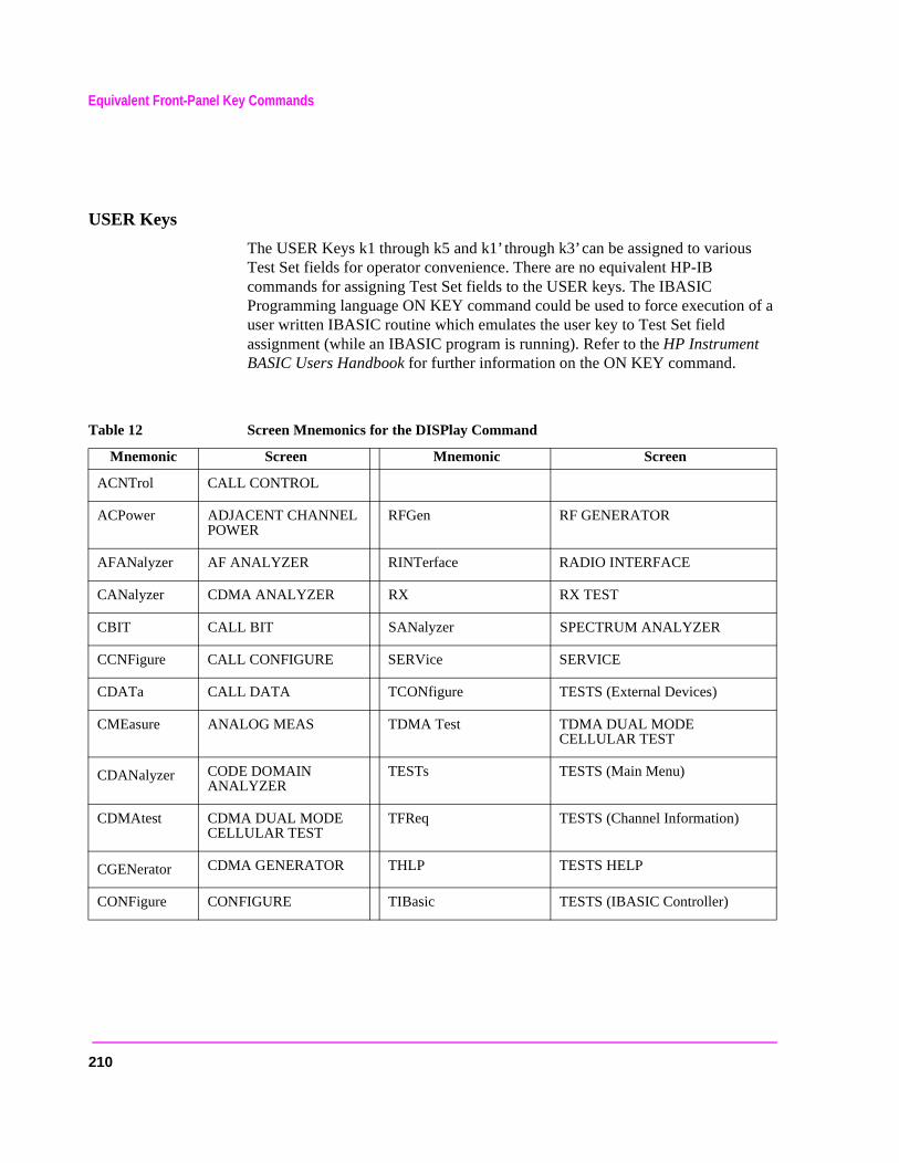
Equivalent Front-Panel Key Commands
USER Keys
The USER Keys k1 through k5 and k1’ through k3’ can be assigned to various Test Set fields for operator convenience. There are no equivalent HP-IB commands for assigning Test Set fields to the USER keys. The IBASIC Programming language ON KEY command could be used to force execution of a user written IBASIC routine which emulates the user key to Test Set field assignment (while an IBASIC program is running). Refer to the HP Instrument BASIC Users Handbook for further information on the ON KEY command.
Table 12 Screen Mnemonics for the DISPlay Command
Mnemonic Screen Mnemonic Screen
ACNTrol CALL CONTROL
ACPower ADJACENT CHANNEL POWER
RFGen RF GENERATOR
AFANalyzer AF ANALYZER RINTerface RADIO INTERFACE
CANalyzer CDMA ANALYZER RX RX TEST
CBIT CALL BIT SANalyzer SPECTRUM ANALYZER
CCNFigure CALL CONFIGURE SERVice SERVICE
CDATa CALL DATA TCONfigure TESTS (External Devices)
CMEasure ANALOG MEAS TDMA Test TDMA DUAL MODE CELLULAR TEST
CDANalyzer CODE DOMAIN ANALYZER
TESTs TESTS (Main Menu)
CDMAtest CDMA DUAL MODE CELLULAR TEST
TFReq TESTS (Channel Information)
CGENerator CDMA GENERATOR THLP TESTS HELP
CONFigure CONFIGURE TIBasic TESTS (IBASIC Controller)
210
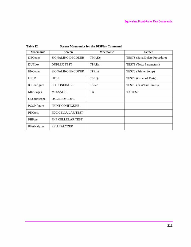
Equivalent Front-Panel Key Commands
DECoder SIGNALING DECODER TMAKe TESTS (Save/Delete Procedure)
DUPLex DUPLEX TEST TPARm TESTS (Tests Parameters)
ENCoder SIGNALING ENCODER TPRint TESTS (Printer Setup)
HELP HELP TSEQn TESTS (Order of Tests)
IOConfigure I/O CONFIGURE TSPec TESTS (Pass/Fail Limits)
MESSages MESSAGE TX TX TEST
OSCilloscope OSCILLOSCOPE
PCONfigure PRINT CONFIGURE
PDCtest PDC CELLULAR TEST
PHPtest PHP CELLULAR TEST
RFANalyzer RF ANALYZER
Table 12 Screen Mnemonics for the DISPlay Command
Mnemonic Screen Mnemonic Screen
211
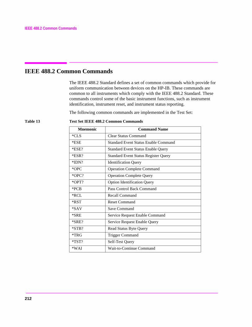
212
IEEE 488.2 Common Commands
IEEE 488.2 Common Commands
The IEEE 488.2 Standard defines a set of common commands which provide for uniform communication between devices on the HP-IB. These commands are common to all instruments which comply with the IEEE 488.2 Standard. These commands control some of the basic instrument functions, such as instrument identification, instrument reset, and instrument status reporting.
The following common commands are implemented in the Test Set:
Table 13 Test Set IEEE 488.2 Common Commands
Mnemonic Command Name
*CLS Clear Status Command
*ESE Standard Event Status Enable Command
*ESE? Standard Event Status Enable Query
*ESR? Standard Event Status Register Query
*IDN? Identification Query
*OPC Operation Complete Command
*OPC? Operation Complete Query
*OPT? Option Identification Query
*PCB Pass Control Back Command
*RCL Recall Command
*RST Reset Command
*SAV Save Command
*SRE Service Request Enable Command
*SRE? Service Request Enable Query
*STB? Read Status Byte Query
*TRG Trigger Command
*TST? Self-Test Query
*WAI Wait-to-Continue Command
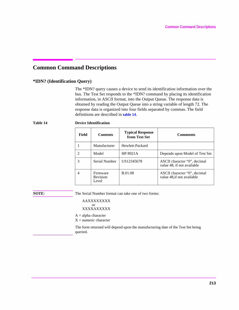
Common Command Descriptions
Common Command Descriptions
*IDN? (Identification Query)
The *IDN? query causes a device to send its identification information over the bus. The Test Set responds to the *IDN? command by placing its identification information, in ASCII format, into the Output Queue. The response data is obtained by reading the Output Queue into a string variable of length 72. The response data is organized into four fields separated by commas. The field definitions are described in table 14.
NOTE: The Serial Number format can take one of two forms:
AAXXXXXXXX orXXXXAXXXXX
A = alpha characterX = numeric character
The form returned will depend upon the manufacturing date of the Test Set being queried.
Table 14 Device Identification
Field Contents Typical Response
from Test Set Comments
1 Manufacturer Hewlett-Packard
2 Model HP 8921A Depends upon Model of Test Set
3 Serial Number US12345678 ASCII character “0”, decimal value 48, if not available
4 Firmware Revision Level
B.01.08 ASCII character “0”, decimal value 48,if not available
213

Common Command Descriptions
Example BASIC program 10 DIM A$[10]20 OUTPUT 714;"*IDN?"30 ENTER 714;A$40 PRINT A$50 END
Example response
Hewlett-Packard,8921A,2423A00189,A.12.04
214
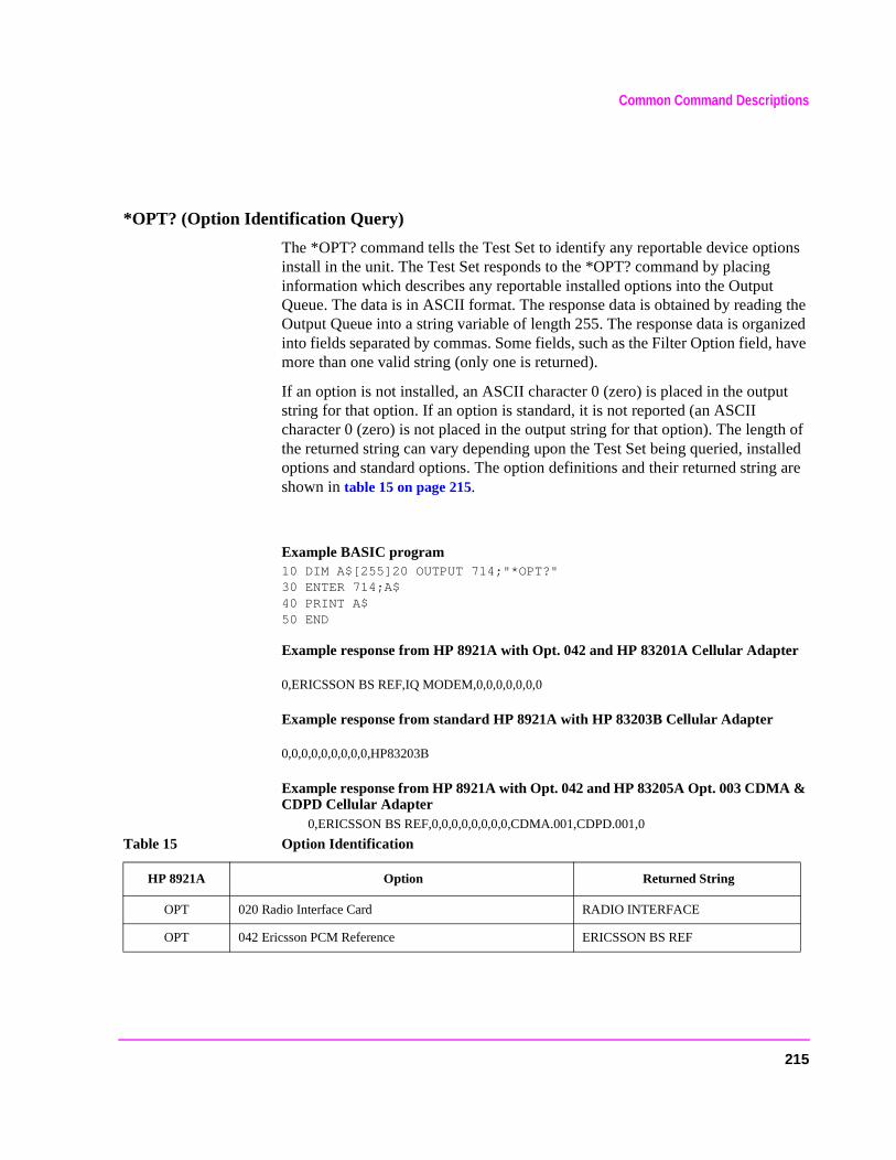
Common Command Descriptions
*OPT? (Option Identification Query)
The *OPT? command tells the Test Set to identify any reportable device options install in the unit. The Test Set responds to the *OPT? command by placing information which describes any reportable installed options into the Output Queue. The data is in ASCII format. The response data is obtained by reading the Output Queue into a string variable of length 255. The response data is organized into fields separated by commas. Some fields, such as the Filter Option field, have more than one valid string (only one is returned).
If an option is not installed, an ASCII character 0 (zero) is placed in the output string for that option. If an option is standard, it is not reported (an ASCII character 0 (zero) is not placed in the output string for that option). The length of the returned string can vary depending upon the Test Set being queried, installed options and standard options. The option definitions and their returned string are shown in table 15 on page 215.
Example BASIC program 10 DIM A$[255]20 OUTPUT 714;"*OPT?"30 ENTER 714;A$40 PRINT A$50 END
Example response from HP 8921A with Opt. 042 and HP 83201A Cellular Adapter
0,ERICSSON BS REF,IQ MODEM,0,0,0,0,0,0,0
Example response from standard HP 8921A with HP 83203B Cellular Adapter
0,0,0,0,0,0,0,0,0,HP83203B
Example response from HP 8921A with Opt. 042 and HP 83205A Opt. 003 CDMA & CDPD Cellular Adapter
0,ERICSSON BS REF,0,0,0,0,0,0,0,0,CDMA.001,CDPD.001,0
Table 15 Option Identification
HP 8921A Option Returned String
OPT 020 Radio Interface Card RADIO INTERFACE
OPT 042 Ericsson PCM Reference ERICSSON BS REF
215
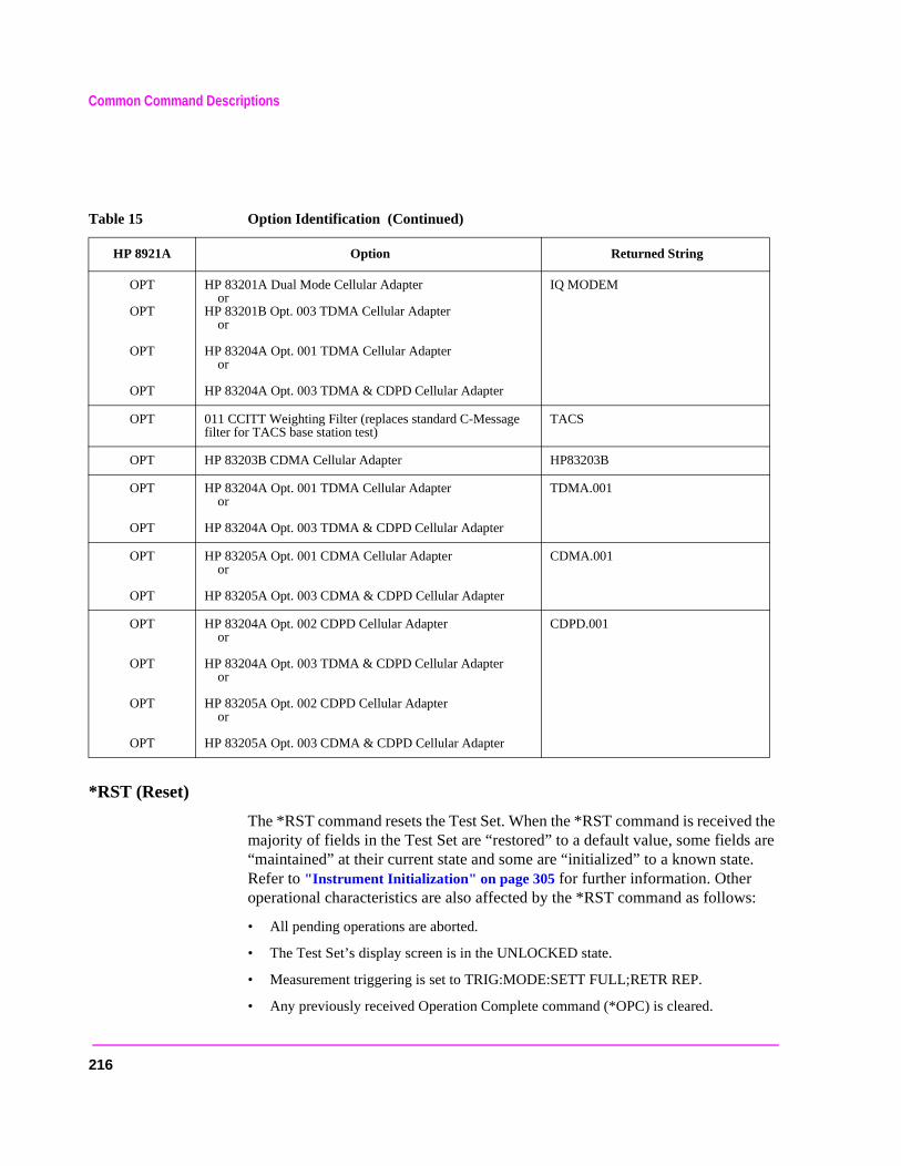
Common Command Descriptions
are .
s:
*RST (Reset)
The *RST command resets the Test Set. When the *RST command is received the majority of fields in the Test Set are “restored” to a default value, some fields“maintained” at their current state and some are “initialized” to a known stateRefer to "Instrument Initialization" on page 305 for further information. Other operational characteristics are also affected by the *RST command as follow
• All pending operations are aborted.
• The Test Set’s display screen is in the UNLOCKED state.
• Measurement triggering is set to TRIG:MODE:SETT FULL;RETR REP.
• Any previously received Operation Complete command (*OPC) is cleared.
OPT
OPT
OPT
OPT
HP 83201A Dual Mode Cellular Adapter or
HP 83201B Opt. 003 TDMA Cellular Adapteror
HP 83204A Opt. 001 TDMA Cellular Adapteror
HP 83204A Opt. 003 TDMA & CDPD Cellular Adapter
IQ MODEM
OPT 011 CCITT Weighting Filter (replaces standard C-Message filter for TACS base station test)
TACS
OPT HP 83203B CDMA Cellular Adapter HP83203B
OPT
OPT
HP 83204A Opt. 001 TDMA Cellular Adapteror
HP 83204A Opt. 003 TDMA & CDPD Cellular Adapter
TDMA.001
OPT
OPT
HP 83205A Opt. 001 CDMA Cellular Adapteror
HP 83205A Opt. 003 CDMA & CDPD Cellular Adapter
CDMA.001
OPT
OPT
OPT
OPT
HP 83204A Opt. 002 CDPD Cellular Adapter or
HP 83204A Opt. 003 TDMA & CDPD Cellular Adapteror
HP 83205A Opt. 002 CDPD Cellular Adapteror
HP 83205A Opt. 003 CDMA & CDPD Cellular Adapter
CDPD.001
Table 15 Option Identification (Continued)
HP 8921A Option Returned String
216

Common Command Descriptions
.
cate, l.
1,
,
• Any previously received Operation Complete query command (*OPC?) is cleared
• The power-up self-test diagnostics are not performed.
• The contents of the SAVE/RECALL registers are not affected.
• Calibration data is not affected.
• The HP-IB interface is not reset (any pending Service Request is not cleared).
• All Enable registers are unaffected: Service Request, Standard Event, CommuniHardware #1, Hardware #2, Operation, Calibration, and Questionable Data/Signa
• All Negative Transition Filter registers are unaffected: Communicate, Hardware #Hardware #2, Operational, Calibration, and Questionable Data/Signal.
• All Positive Transition Filter registers are unaffected: Communicate, Hardware #1Hardware #2, Operational, Calibration, and Questionable Data/Signal.
• The contents of the RAM memory are unaffected.
• The contents of the Output Queue are unaffected.
• The contents of the Error Queue are unaffected.
217
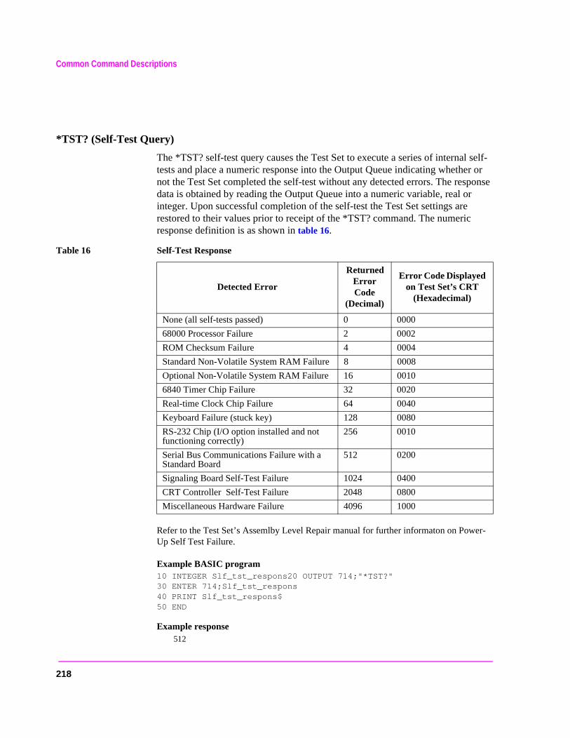
Common Command Descriptions
er-
*TST? (Self-Test Query)
The *TST? self-test query causes the Test Set to execute a series of internal self-tests and place a numeric response into the Output Queue indicating whether or not the Test Set completed the self-test without any detected errors. The response data is obtained by reading the Output Queue into a numeric variable, real or integer. Upon successful completion of the self-test the Test Set settings are restored to their values prior to receipt of the *TST? command. The numeric response definition is as shown in table 16.
Refer to the Test Set’s Assemlby Level Repair manual for further informaton on PowUp Self Test Failure.
Example BASIC program 10 INTEGER Slf_tst_respons20 OUTPUT 714;"*TST?"30 ENTER 714;Slf_tst_respons40 PRINT Slf_tst_respons$50 END
Example response 512
Table 16 Self-Test Response
Detected Error
Returned Error Code
(Decimal)
Error Code Displayed on Test Set’s CRT
(Hexadecimal)
None (all self-tests passed) 0 0000
68000 Processor Failure 2 0002
ROM Checksum Failure 4 0004
Standard Non-Volatile System RAM Failure 8 0008
Optional Non-Volatile System RAM Failure 16 0010
6840 Timer Chip Failure 32 0020
Real-time Clock Chip Failure 64 0040
Keyboard Failure (stuck key) 128 0080
RS-232 Chip (I/O option installed and not functioning correctly)
256 0010
Serial Bus Communications Failure with a Standard Board
512 0200
Signaling Board Self-Test Failure 1024 0400
CRT Controller Self-Test Failure 2048 0800
Miscellaneous Hardware Failure 4096 1000
218
Common Command Descriptions
l
ystemdo not Callrogramte bit
sing
rogram
tatus
*OPC (Operation Complete)
The *OPC command allows for synchronization between the Test Set and an external controller. The *OPC command causes the Test Set to set bit 0, Operation Complete, in the Standard Event Status Register to the TRUE, logic 1, state when the Test Set completes all pending operations. Detection of the Operation Complete message can be accomplished by continuous polling of the Standard Event Status Register using the *ESR? common query command. However, using a service request eliminates the need to poll the Standard Event Status Register thereby freeing the controller to do other useful work.
NOTE: The Test Set contains signal generation and signal measurement instrumentation. The instrument control processor is able to query the signal measurement instrumentation to determine if a measurement cycle has completed. However, the instrument control processor is not able to query the signal generation instrumentation to determine if the signal(s) have settled. In order to ensure that all signals have settled to proper values, the instrument control processor initiates a one-second delay upon receipt of the *OPC, *OPC? and *WAI commands. In parallel with the one-second timer the instrument control processor commands all active measurements to tell it when the measurement(s) are done. When all active measurements are done and the one-second timer has elapsed, the *OPC, *OPC? and *WAI commands are satisfied.
If the *OPC, *OPC? or *WAI common commands are used to determine when a measurement has completed and the measurement is either in the OFF State or unavailable (four dashed lines on CRT display “- - - -” ), the *OPC, *OPC? or *WAI command wilnever complete.
CAUTION: The *OPC command should not be used for determining if a Call Processing Subsstate command has completed successfully. Call Processing Subsystem states complete, a state is either active or not active. Using the *OPC command with aProcessing Subsystem state command results in a deadlock condition. The control pwill continuously query the Standard Event Status Register for the Operation Completo be set but the bit will never be set because the command never ‘completes’.
For example, the following command sequence should not be used:OUTPUT 714;"CALLP:ACTive;*OPC"
The *OPC command should not be used with any of the following Call ProcesSubsystem commands: :ACTive, :REGister, :PAGE, :HANDoff, :RELease.
The Call Processing Subsystem Status Register Group should be used to control pflow. Refer to chapter 8, "Programming The Call Processing Subsystem" forinformation on controlling program flow using the Call Processing Subsystem SRegister Group.
219
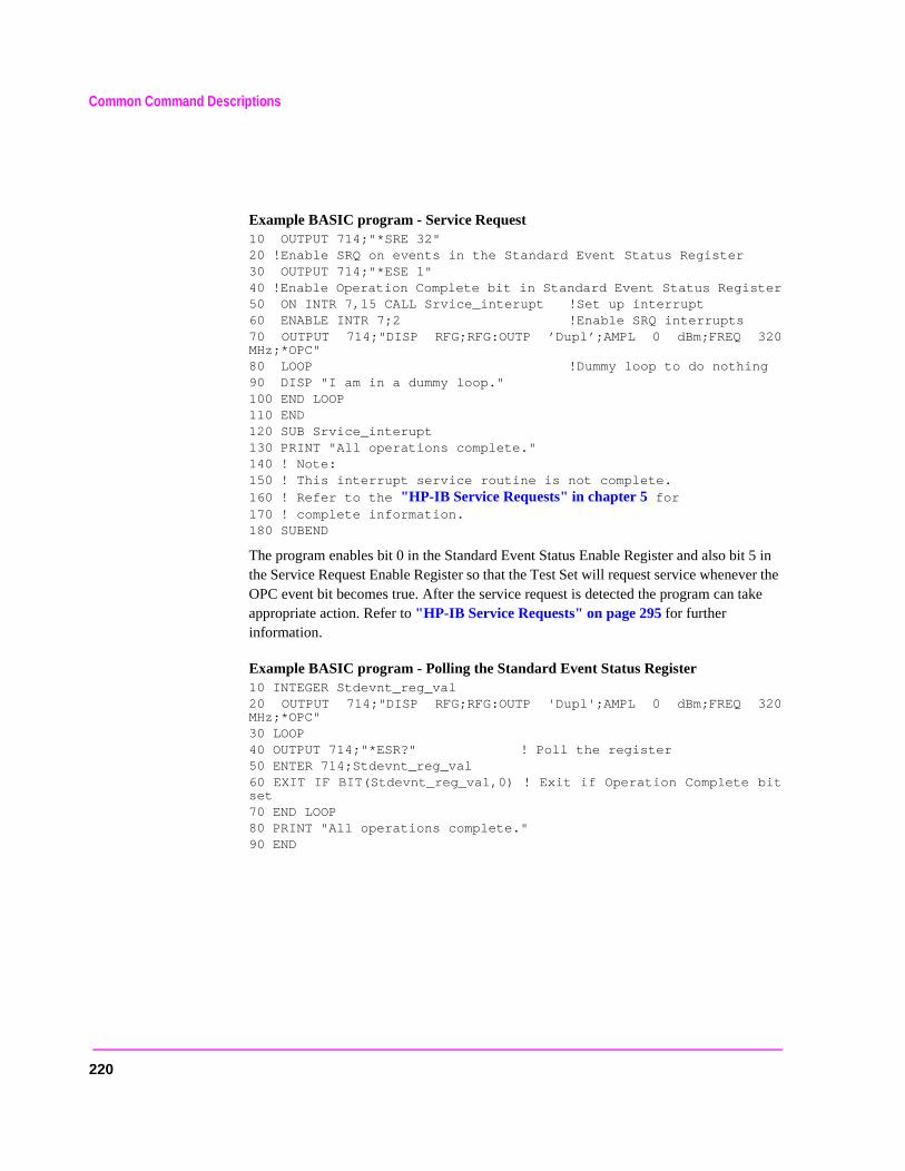
Common Command Descriptions
Example BASIC program - Service Request 10 OUTPUT 714;"*SRE 32"20 !Enable SRQ on events in the Standard Event Status Register30 OUTPUT 714;"*ESE 1"40 !Enable Operation Complete bit in Standard Event Status Register50 ON INTR 7,15 CALL Srvice_interupt !Set up interrupt60 ENABLE INTR 7;2 !Enable SRQ interrupts70 OUTPUT 714;"DISP RFG;RFG:OUTP ’Dupl’;AMPL 0 dBm;FREQ 320MHz;*OPC"80 LOOP !Dummy loop to do nothing90 DISP "I am in a dummy loop."100 END LOOP110 END120 SUB Srvice_interupt130 PRINT "All operations complete."140 ! Note:150 ! This interrupt service routine is not complete.160 ! Refer to the "HP-IB Service Requests" in chapter 5 for170 ! complete information.180 SUBEND
The program enables bit 0 in the Standard Event Status Enable Register and also bit 5 in the Service Request Enable Register so that the Test Set will request service whenever the OPC event bit becomes true. After the service request is detected the program can take appropriate action. Refer to "HP-IB Service Requests" on page 295 for further information.
Example BASIC program - Polling the Standard Event Status Register 10 INTEGER Stdevnt_reg_val20 OUTPUT 714;"DISP RFG;RFG:OUTP 'Dupl';AMPL 0 dBm;FREQ 320MHz;*OPC"30 LOOP40 OUTPUT 714;"*ESR?" ! Poll the register50 ENTER 714;Stdevnt_reg_val60 EXIT IF BIT(Stdevnt_reg_val,0) ! Exit if Operation Complete bitset70 END LOOP80 PRINT "All operations complete."90 END
220

Common Command Descriptions
ll
ystemdo not Call
rogram the
sing
rogram
tatus
*OPC? (Operation Complete Query)
The *OPC? query allows for synchronization between the Test Set and an external controller by reading the Output Queue or by polling the Message Available (MAV) bit in the Status Byte Register. The *OPC? query causes the Test Set to place an ASCII character, 1, into its Output Queue when the Test Set completes all pending operations. A consequence of this action is that the MAV bit in the Status Byte Register is set to the 1 state.
NOTE: The Test Set contains signal generation and signal measurement instrumentation. The instrument control processor is able to query the signal measurement instrumentation to determine if a measurement cycle has completed. However, the instrument control processor is not able to query the signal generation instrumentation to determine if the signal(s) have settled. In order to ensure that all signals have settled to proper values, the instrument control processor initiates a one-second delay upon receipt of the *OPC, *OPC? and *WAI commands. In parallel with the one-second timer the instrument control processor commands all active measurements to tell it when the measurement(s) are done. When all active measurements are done and the one-second timer has elapsed, the *OPC, *OPC? and *WAI commands are satisfied.
If the *OPC, *OPC? or *WAI common commands are used to determine when a measurement has completed and the measurement is either in the OFF State or unavailable ( four dashed lines on CRT display “- - - -” ), the *OPC, *OPC? or *WAI command winever complete.
CAUTION: The *OPC? command should not be used for determining if a Call Processing Subsstate command has completed successfully. Call Processing Subsystem states complete, a state is either active or not active. Using the *OPC? command with aProcessing Subsystem state command results in a deadlock condition. The control pwill continuously query the Output Queue for a 1 but the 1 will never be placed inOutput Queue because the command never ‘completes’.
For example, the following command sequence should not be used:OUTPUT 714;"CALLP:ACTive;*OPC?"
The *OPC? command should not be used with any of the following Call ProcesSubsystem commands: :ACTive, :REGister, :PAGE, :HANDoff, :RELease.
The Call Processing Subsystem Status Register Group should be used to control pflow. Refer to chapter 8, "Programming The Call Processing Subsystem" forinformation on controlling program flow using the Call Processing Subsystem SRegister Group.
221
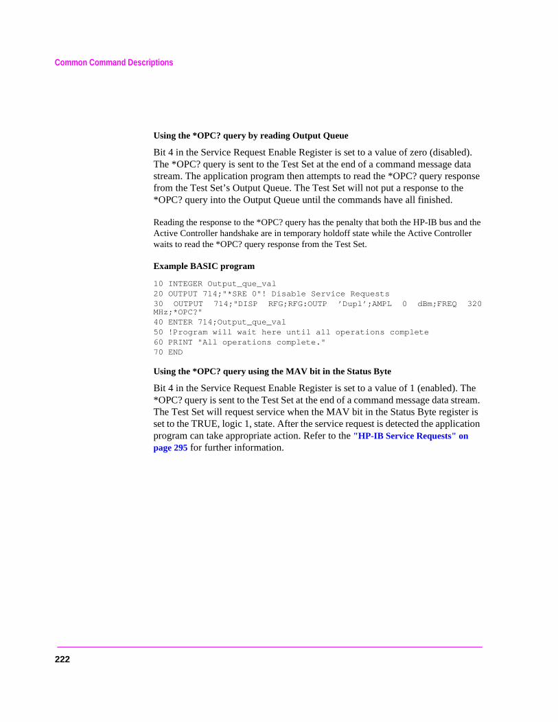
Common Command Descriptions
e
The tream. r is ation
Using the *OPC? query by reading Output Queue
Bit 4 in the Service Request Enable Register is set to a value of zero (disabled). The *OPC? query is sent to the Test Set at the end of a command message data stream. The application program then attempts to read the *OPC? query response from the Test Set’s Output Queue. The Test Set will not put a response to th*OPC? query into the Output Queue until the commands have all finished.
Reading the response to the *OPC? query has the penalty that both the HP-IB bus and the Active Controller handshake are in temporary holdoff state while the Active Controller waits to read the *OPC? query response from the Test Set.
Example BASIC program
10 INTEGER Output_que_val20 OUTPUT 714;"*SRE 0"! Disable Service Requests30 OUTPUT 714;"DISP RFG;RFG:OUTP ’Dupl’;AMPL 0 dBm;FREQ 320MHz;*OPC?"40 ENTER 714;Output_que_val50 !Program will wait here until all operations complete60 PRINT "All operations complete."70 END
Using the *OPC? query using the MAV bit in the Status Byte
Bit 4 in the Service Request Enable Register is set to a value of 1 (enabled).*OPC? query is sent to the Test Set at the end of a command message data sThe Test Set will request service when the MAV bit in the Status Byte registeset to the TRUE, logic 1, state. After the service request is detected the applicprogram can take appropriate action. Refer to the "HP-IB Service Requests" on page 295 for further information.
222
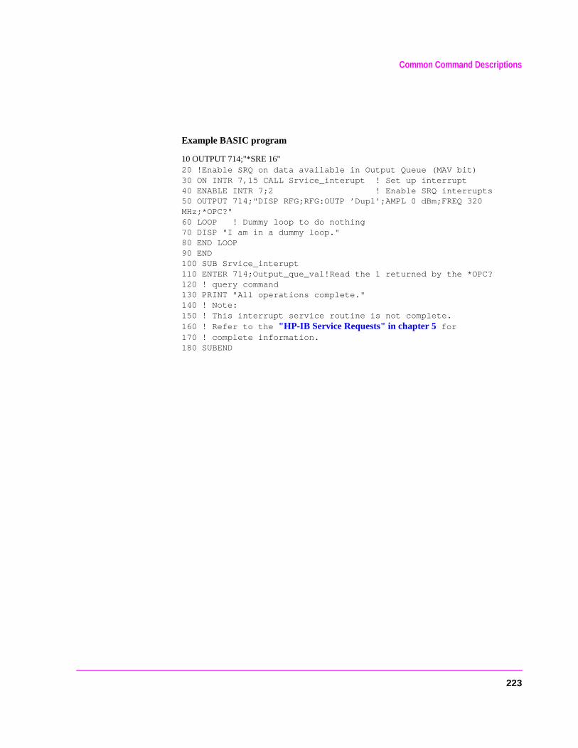
Common Command Descriptions
Example BASIC program
10 OUTPUT 714;"*SRE 16"20 !Enable SRQ on data available in Output Queue (MAV bit)30 ON INTR 7,15 CALL Srvice_interupt ! Set up interrupt40 ENABLE INTR 7;2 ! Enable SRQ interrupts50 OUTPUT 714;"DISP RFG;RFG:OUTP ’Dupl’;AMPL 0 dBm;FREQ 320MHz;*OPC?"60 LOOP ! Dummy loop to do nothing70 DISP "I am in a dummy loop."80 END LOOP90 END100 SUB Srvice_interupt110 ENTER 714;Output_que_val!Read the 1 returned by the *OPC?120 ! query command130 PRINT "All operations complete."140 ! Note:150 ! This interrupt service routine is not complete.160 ! Refer to the "HP-IB Service Requests" in chapter 5 for170 ! complete information.180 SUBEND
223

Common Command Descriptions
stemdo notCallwill notmand
rogram
tatus
*WAI (Wait To Complete)
The *WAI command stops the Test Set from executing any further commands or queries until all commands or queries preceding the *WAI command have completed.
Example BASIC statement OUTPUT 714;"DISP RFG;RFG:OUTP ’Dupl’;*WAI;AMPL 0 dBm"
NOTE: The Test Set contains signal generation and signal measurement instrumentation. The instrument control processor is able to query the signal measurement instrumentation to determine if a measurement cycle has completed. However, the instrument control processor is not able to query the signal generation instrumentation to determine if the signal(s) have settled. In order to ensure that all signals have settled to proper values, the instrument control processor initiates a one-second delay upon receipt of the *OPC, *OPC? and *WAI commands. In parallel with the one-second timer the instrument control processor commands all active measurements to tell it when the measurement(s) are done. When all active measurements are done and the one-second timer has elapsed, the *OPC, *OPC? and *WAI commands are satisfied.
If the *OPC, *OPC? or *WAI common commands are used to determine when a measurement has completed and the measurement is either in the OFF State or unavailable ( four dashed lines on CRT display “- - - -” ), the *OPC, *OPC? or *WAI command will never complete.
CAUTION: The *WAI command should not be used for determining if a Call Processing Subsystate command has completed successfully. Call Processing Subsystem states complete, a state is either active or not active. Using the *WAI command with a Processing Subsystem state command results in a deadlock condition. The Test Set process any further HP-IB commands unitl the Call Processing Subsystem compreceeding the *WAI command completes but the command never ‘completes’.
For example, the following command sequence should not be used:
OUTPUT 714;"CALLP:ACTive;*WAI;:CALLP:REGister"
The *WAI command should not be used with any of the following CallProcessing Subsystem commands: :ACTive, :REGister, :PAGE, :HANDoff,:RELease.
The Call Processing Subsystem Status Register Group should be used to control pflow. Refer to chapter 8, "Programming The Call Processing Subsystem" forinformation on controlling program flow using the Call Processing Subsystem SRegister Group.
224
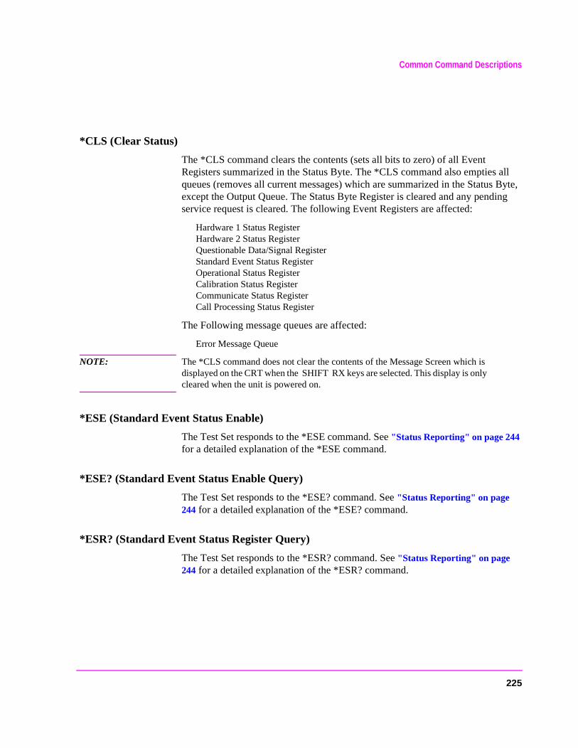
Common Command Descriptions
*CLS (Clear Status)
The *CLS command clears the contents (sets all bits to zero) of all Event Registers summarized in the Status Byte. The *CLS command also empties all queues (removes all current messages) which are summarized in the Status Byte, except the Output Queue. The Status Byte Register is cleared and any pending service request is cleared. The following Event Registers are affected:
Hardware 1 Status Register Hardware 2 Status Register Questionable Data/Signal Register Standard Event Status Register Operational Status Register Calibration Status Register Communicate Status Register Call Processing Status Register
The Following message queues are affected:
Error Message Queue
NOTE: The *CLS command does not clear the contents of the Message Screen which is displayed on the CRT when the SHIFT RX keys are selected. This display is only cleared when the unit is powered on.
*ESE (Standard Event Status Enable)
The Test Set responds to the *ESE command. See "Status Reporting" on page 244 for a detailed explanation of the *ESE command.
*ESE? (Standard Event Status Enable Query)
The Test Set responds to the *ESE? command. See "Status Reporting" on page 244 for a detailed explanation of the *ESE? command.
*ESR? (Standard Event Status Register Query)
The Test Set responds to the *ESR? command. See "Status Reporting" on page 244 for a detailed explanation of the *ESR? command.
225
Common Command Descriptions
*SRE (Service Request Enable)
The Test Set responds to the *SRE command. "HP-IB Service Requests" on page 295 for a detailed explanation of the *SRE command.
*SRE? (Service Request Enable Query)
The Test Set responds to the *SRE? command. "HP-IB Service Requests" on page 295 for a detailed explanation of the *SRE? command.
*STB? (Status Byte Query)
The Test Set responds to the *STB? command. "Status Reporting" on page 244 for a detailed explanation of the *STB? command.
*TRG (Trigger)
The *TRG command is equivalent to the IEEE 488.1 defined Group Execute Trigger (GET) message and has the same effect as a GET when received by the Test Set. The Test Set responds to the *TRG command by triggering all currently active measurements.
*PCB (Pass Control Back)
The Test Set accepts the *PCB command. "Passing Control" on page 318 for a detailed explanation of the *PCB command.
226

Common Command Descriptions
*RCL (Recall Instrument State)
The *RCL command restores the state of the Test Set from a file previously stored in battery-backed internal memory, on a memory card, on a RAM disk, or on an external disk. The *RCL command is followed by a decimal number in the range of 0 to 99 which indicates which Test Set SAVE/RECALL file to recall. The mass storage location for SAVE/RECALL files is selected using the SAVE/RECALL field on the I/O CONFIGURE screen.
The *RCL command cannot be used to recall files with names which contain non-numeric characters or a decimal number greater than 99. To recall SAVE/RECALL files saved with names which contain non-numeric characters or a decimal number greater than 99, use the REG:RECall filename command (see "RECALL" on page 206).
*SAV (Save Instrument State)
The *SAV command saves the present state of the Test Set into a file in battery-backed internal memory, on a memory card, on a RAM disk, or on an external disk. The *SAV command is followed by a decimal number in the range of 0 to 99 which indicates the name of the stored SAVE/RECALL file. The mass storage location for SAVE/RECALL files is selected using the SAVE/RECALL field on the I/O CONFIGURE screen.
The *SAV command cannot be used to save the present state of the Test Set to a file with a name which contains non-numeric characters or a decimal number greater than 99. To save the present state of the Test Set to a file with a name which contains non-numeric characters or a decimal number greater than 99, use the REG:SAVE filename command (see "SAVE" on page 206).
227

Triggering Measurements
ow.” est Set
Triggering Measurements
The measurement cycle is started (triggered) by the occurrence of a trigger event. The reliability and accuracy of the measurement result, as well as the speed of the measurement cycle are influenced by the trigger mode in effect at the time the trigger event occurs. Some modes are faster than others; some modes provide settling for signals that may contain transients. The best triggering mode to use will depend upon the measurement requirements (repeatability, accuracy and speed).
Trigger Event
The Test Set starts a measurement cycle when a valid Trigger Event is received. A Trigger Event is analogous to telling the Test Set to “start the measurement nThere are three commands that can be used to issue a Trigger Event to the Tthrough HP-IB:
• A Group Execute Trigger Command (GET) as defined by IEEE 488.1-1987
• A Trigger Common Command (*TRG) as defined by IEEE 488.2-1987
• A :TRIGger:IMMediate Test Set command.
All three commands are equivalent and have the same effect when received by the Test Set. The Test Set responds to the three commands by triggering all currently active measurements. A measurement is defined as active if
1. it is on the currently displayed screen
2. it is in the ON state
From a programming perspective this means that the screen which contains the measurement of interest must be made available using the DISPlay command and that the measurement STATe must be ON.
228

Triggering Measurements
Trigger Modes
The Trigger Mode is defined by two parameters: retriggering and settling.
Retriggering
Retriggering refers to what a measurement does once it has completed a measurement cycle. There are two options:
1. Single retriggering causes the measurement cycle to stop once a valid measurement result has been obtained. A valid trigger command must be received to start the measurement again. When a measurement cycle is completed, the values for all active measurements are held until another trigger command is received. This allows the control program to query a group of measurements that were triggered at the same time. This is the same functionality as the front-panel HOLD function.
When the trigger mode is set to single retriggering, consecutive queries of the same measurement (with no intervening trigger event) will return the same value. Measurements that rely on external signals or hardware-generated events (such as the DTMF Decoder) must be re-armed with a new trigger command before another measurement can be made.
2. Repetitive retriggering causes the measurement cycle to immediately start over once a valid measurement result has been obtained. No trigger event must be received to start the measurement again. Repetitive retriggering will cause measurements that rely on external signals or hardware generated events (such as the DTMF Decoder) to bere-armed upon completion of a measurement cycle (a valid measurement result has been obtained ). When the trigger mode is set to repetitive retriggering, consecutive queries of the same measurement return new measured values.
NOTE: If a measurement cycle does not successfully obtain a valid measurement result, it will continue to try until it does or the measurement trigger is aborted. This is true for both retriggering modes.
229

Triggering Measurements
Settling
Settling refers to the amount of delay introduced to allow signal transients to propagate through the analysis chain and settle out. There are two options:
1. Full settling introduces the appropriate delay for all signal transients which might have occurred at the front panel at just the same time as the trigger event, to pass through the analysis chain and settle out. Delays are also inserted to allow for internal hardware transients to settle.
2. Fast settling introduces no delay for internal or external signal transients to settle. The programmer must account for transient settling before issuing the Trigger Event.
NOTE: There will still be delays introduced by the couplings between autotuning and autoranging. If the programmer wishes to remove these delays as well, all autoranging and autotuning functions must be turned OFF and the program must explicitly set the ranging amplifiers and the frequency tuning. Delays introduced by the measurement processes themselves cannot be eliminated.
Bus Lock Up: If a measurement cycle does not successfully obtain a valid measurement result, it will continue to try until it does or until the measurement trigger is aborted. This is true for both retriggering modes. This has the consequence that both the HP-IB bus and the Active Controller handshake are in a temporary holdoff state while the Active Controller waits to read the measurement result from the Test Set.
The control program should include measurement time-out routines that CLEAR the bus and ABORt the trigger if a measurement does not complete within a specified amount of time. This provides a method of preventing the bus from remaining in the temporary holdoff state indefinitely.
230
Triggering Measurements
Default Trigger Mode
The Trigger mode is set to FULL SETTling and REPetitive RETRiggering whenever
• the Test Set is powered on
• the PRESET key is selected
• the Test Set is put into LOCAL mode
• the Test Set is reset using the *RST command
• the Test Set is put in remote mode and no other trigger mode is set
Local/Remote Triggering Changes
Local To Remote Transitions
The Test Set switches from Local to Remote mode upon receipt of the Remote message (REN bus line true and Test Set is addressed to listen). No instrument settings are changed by the transition from Local to Remote mode, but triggering is set to the state it was last set to in Remote mode (if no previous setting, the default is FULL SETTling and REPetitive RETRiggering).
When the Test Set makes a transition from local to remote mode, all currently active measurements are flagged as invalid causing any currently available measurement results to become unavailable. If the HP-IB trigger mode is :RETR REP then a new measurement cycle is started and measurement results will be available for all active measurements when valid results have been obtained. If the HP-IB trigger mode is :RETR SING then a measurement cycle must be started by issuing a trigger event. Refer to "Triggering Measurements" on page 228 for more information.
Remote To Local Transitions
The Test Set switches from Remote to Local mode upon receipt of the Local message (Go To Local bus message is sent and Test Set is addressed to listen) or receipt of the Clear Lockout/Set Local message (REN bus line false). No instrument settings are changed by the transition from Remote to Local mode, but triggering is reset to FULL SETTling and REPetitive RETRiggering.
231
Triggering Measurements
t . ned
on a m to
Trigger Commands
:TRIGger:IMMediate
The :TRIGger:IMMediate command tells the Test Set to “start a measuremencycle now.” The type of triggering used depends on the trigger mode settingsThis command is equivalent to a Group Execute Trigger Command (GET) asdefined by IEEE 488.1-1987 or a Trigger Common Command (*TRG) as defiby IEEE 488.2-1987. The IMMediate statement is implied and is optional.
Syntax
:TRIGger:IMMediate
Example
OUTPUT 714;"TRIG:IMM"
orOUTPUT 714;"TRIG"
:ABORt
The :ABORt command tells the Test Set to stop a currently executing measurement cycle and get ready for a new HP-IB command. If for any reasvalid measurement cannot be made, this command allows the control prograterminate the requested measurement and regain control of the Test Set.
Syntax
:TRIGger:ABORt
Example
OUTPUT 714;"TRIG:ABOR"
232
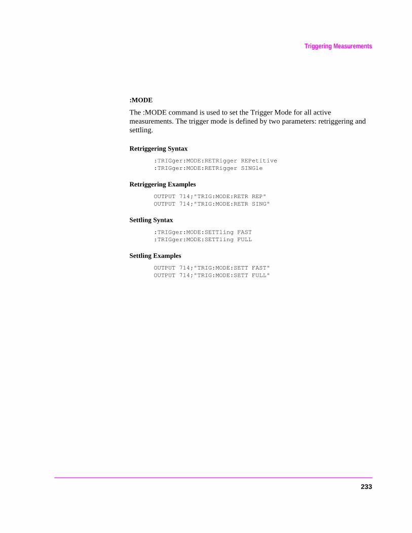
Triggering Measurements
:MODE
The :MODE command is used to set the Trigger Mode for all active measurements. The trigger mode is defined by two parameters: retriggering and settling.
Retriggering Syntax
:TRIGger:MODE:RETRigger REPetitive:TRIGger:MODE:RETRigger SINGle
Retriggering Examples
OUTPUT 714;"TRIG:MODE:RETR REP"OUTPUT 714;"TRIG:MODE:RETR SING"
Settling Syntax
:TRIGger:MODE:SETTling FAST:TRIGger:MODE:SETTling FULL
Settling Examples
OUTPUT 714;"TRIG:MODE:SETT FAST"OUTPUT 714;"TRIG:MODE:SETT FULL"
233

Triggering Measurements
urn-
ch
Trigger Mode and Measurement Speed
There are two generalized scenarios which can be described for HP-IB triggering control. The first is to have the Test Set return measurement results as fast as possible and assume that the control program will handle all transient settling and value tolerance activities. The second scenario is to have the Test Set return the most reliable, accurate, fully settled measurement results that it can, even if it takes some time to do this.
Trigger Mode Settings for Fastest Measurements
Use the following Test Set configuration and trigger mode settings for the fastest possible measurement speed. See "Increasing Measurement Throughput" on page 238 for more information on improving measurement throughput.
1. Range hold all auto-ranging and auto-tuning functions and set ranges and frequency through HP-IB. This avoids autoranging/autotuning delays.
2. Use REPetitive RETRiggering. This avoids Trigger Event processing delays.
3. Use FAST SETTling. This avoids the signal transient settling delays.1
4. Turn off all measurements that are not required. This avoids any delays caused by contention for measurement resources within the Test Set.
Trigger Mode Settings for Most Reliable Measurements
Use the following Test Set configuration and trigger mode settings to get the most accurate, most reliable, fully settled measurement results. See "Increasing Measurement Throughput" on page 238 for more information on improving measurement throughput.
1. Turn on all autoranging and autotuning functions. (This is the Test Set’s default ton and PRESET state.)
2. Use SINGle RETRiggering.
3. Use FULL SETTling.
4. Individually trigger each measurement.
1. Using FAST settling increases the possibility that transient signal conditions whioccur during the measurement cycle will be included in the measurement result.
234
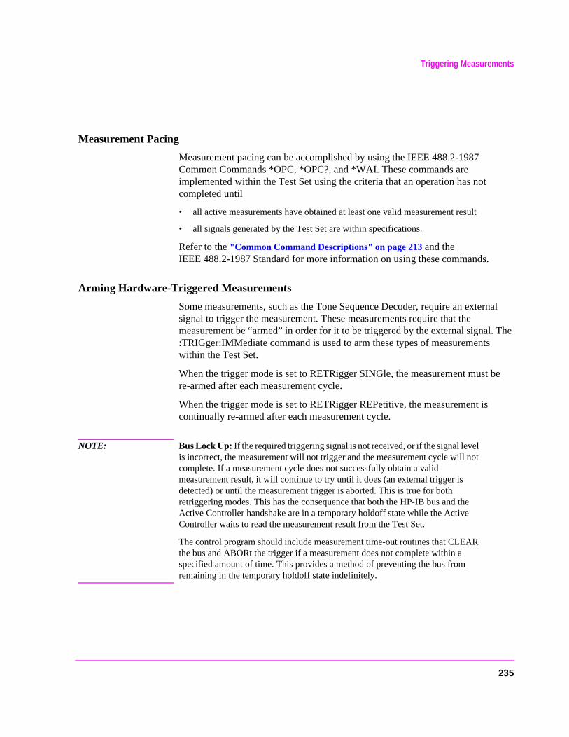
Triggering Measurements
The
be
Measurement Pacing
Measurement pacing can be accomplished by using the IEEE 488.2-1987 Common Commands *OPC, *OPC?, and *WAI. These commands are implemented within the Test Set using the criteria that an operation has not completed until
• all active measurements have obtained at least one valid measurement result
• all signals generated by the Test Set are within specifications.
Refer to the "Common Command Descriptions" on page 213 and the IEEE 488.2-1987 Standard for more information on using these commands.
Arming Hardware-Triggered Measurements
Some measurements, such as the Tone Sequence Decoder, require an external signal to trigger the measurement. These measurements require that the measurement be “armed” in order for it to be triggered by the external signal.:TRIGger:IMMediate command is used to arm these types of measurementswithin the Test Set.
When the trigger mode is set to RETRigger SINGle, the measurement must re-armed after each measurement cycle.
When the trigger mode is set to RETRigger REPetitive, the measurement is continually re-armed after each measurement cycle.
NOTE: Bus Lock Up: If the required triggering signal is not received, or if the signal level is incorrect, the measurement will not trigger and the measurement cycle will not complete. If a measurement cycle does not successfully obtain a valid measurement result, it will continue to try until it does (an external trigger is detected) or until the measurement trigger is aborted. This is true for both retriggering modes. This has the consequence that both the HP-IB bus and the Active Controller handshake are in a temporary holdoff state while the Active Controller waits to read the measurement result from the Test Set.
The control program should include measurement time-out routines that CLEAR the bus and ABORt the trigger if a measurement does not complete within a specified amount of time. This provides a method of preventing the bus from remaining in the temporary holdoff state indefinitely.
235

Triggering Measurements
236
5
Advanced Operations
237

Chapter 5, Advanced OperationsIncreasing Measurement Throughput
Increasing Measurement Throughput
Measurement throughput is defined as the number of measurements made per unit of time. When operating the Test Set in the Internal or External Automatic Control Mode, measurement throughput is influenced by measurement speed, measurement setup time, and execution speed of the control program. Each of these factors is, in turn, influenced by several parameters. The following sections discuss the parameters and their effect on measurement throughput.
Optimizing Measurement Speed
Measurement speed is defined as the time required to complete one measurement cycle after receipt of a valid trigger event. Measurement speed is influenced by the following four parameters.
1. Trigger Mode
The Trigger Mode affects the time-to-first-reading and the length of the measurement cycle and is defined by two parameters: retriggering and settling. Retriggering refers to what a measurement does once it has completed a measurement cycle. Settling refers to the amount of delay introduced to allow signal transients to propagate through the analysis chain and settle out. Refer to "Triggering Measurements" on page 228 for information on Trigger Mode and its impact on measurement speed.
2. Autoranging/Autotuning
The autoranging and autotuning functions continuously calculate and adjust gain and frequency tuning settings to provide the optimum instrument setup for each measurement. This results in greater measurement accuracy but increases measurement cycle time. The autoranging and autotuning functions can be turned off to decrease the measurement cycle time.
238

Chapter 5, Advanced OperationsIncreasing Measurement Throughput
Time-to-first-reading after making new settings is usually much slower than the repetitive reading rate once the first reading has been returned. The main contributor to first-reading measurement time is hardware autoranging. Hardware autoranging time can be eliminated by first establishing the expected AF and RF signal levels into the Test Set. With these signal levels present, the Test Set will autorange, allowing the operator to determine the attenuation and gain settings of the RF input attenuator as displayed in the RF ANALYZER screen, and to determine the various IF and audio gains as displayed in the AF ANALYZER screen. The attenuation and gain settings determined in manual mode should be recorded for use in writing the program.
In the control program, select Gain Control, Hold (default is Auto), and make the settings recorded in manual mode. When the control program runs, the signal levels into the Test Set need to remain relatively constant since autoranging has been disabled.
If the automatic functions are turned off, the control program must set the gain stages and frequency tuning before triggering a measurement. The automatic functions can be turned off as follows:
Disable RF autotuning by setting the Tune Mode field to Manual using the following command:
:RFAN:TMOD ’MANUAL’
Disable RF autoranging by setting the Input Atten field to Hold using the following command:
:RFAN:ATT:MODE ’HOLD’
Disable AF autoranging by setting the Gain Cntl field to Hold using the following command:
:AFAN:RANG ’HOLD’
239

Chapter 5, Advanced OperationsIncreasing Measurement Throughput
y times uency. time
ds to
3. Frequency Counter Gate Time
The frequency counter’s gate time specifies how long the RF or AF frequenccounter samples the signal before displaying the measured result. Short gatemeasure instantaneous frequency and long gate times measure average freqThe longer the gate time, the longer the measurement cycle. The proper gateis determined by the measurement requirements. Use the following commanset gate times:
For AF frequency measurements, set the AF Analyzer’s gate time with the AF Cnt Gate field, using the following command:
:AFAN:GTIM <value> MS
For RF frequency measurements, set the RF Analyzer’s gate time with the RF Cnt Gate field, using the following command:
:RFAN:GTIM <value> MS
4. Number of Active Measurements
The Test Set is capable of making many measurements simultaneously. Measurements are either in the active state (ON) or in the inactive state (OFF). When the Test Set receives a trigger event, all active measurements are triggered. A measurement cycle is complete when all active measurements have obtained a valid measurement result. To decrease the measurement cycle time, all unused measurements should be set to the inactive state (turned OFF). Turning OFF unused measurements will have the greatest impact on reading repetition rate. Use the STATe command to turn OFF all unneeded measurements on the displayed screen.
240
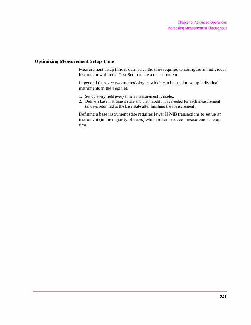
Chapter 5, Advanced OperationsIncreasing Measurement Throughput
Optimizing Measurement Setup Time
Measurement setup time is defined as the time required to configure an individual instrument within the Test Set to make a measurement.
In general there are two methodologies which can be used to setup individual instruments in the Test Set:
1. Set up every field every time a measurement is made.,2. Define a base instrument state and then modify it as needed for each measurement
(always returning to the base state after finishing the measurement).
Defining a base instrument state requires fewer HP-IB transactions to set up an instrument (in the majority of cases) which in turn reduces measurement setup time.
241

Chapter 5, Advanced OperationsIncreasing Measurement Throughput
-
state.
from
Optimizing the Execution Speed of the Control Program
Execution speed of the control program is defined as the time required to execute a given number of program lines. .
Each time the HP-IB is accessed, a given amount of time is required to configure the devices on the bus for data transfer. Every time a BASIC or IBASIC OUTPUT or ENTER statement is executed this bus configuration time is incurred. The total amount of bus configuration time expended for a given number of program lines can be minimized by reducing the number of OUTPUT and ENTER statements used in the control program. This is accomplished by combining several commands into one HP-IB transaction. Execution speed of the control program is influenced by the use of compound commands and screen display time as described in the following paragraphs
Compound Commands for Combining OUTPUT Statements
To reduce the number of OUTPUT statements used to make the desired settings within one screen, string together multiple settings within one OUTPUT statement. This is accomplished using the ; (semicolon) separator and the ;: (semicolon colon) separator.
The ; (semicolon) Separator. The ; (semicolon) separator tells the Test Set’s HPIB command parser to back up one level of command hierarchy and accept the next command at the same level as the previous command. The following examples illustrate proper use of the semicolon separator:
Example #1
OUTPUT 714;"RFG:AMPL -66 DBM;FREQ 500 MHZ;AMPL:STAT ON" !This OUTPUT statement sets the RF generator’s amplitude, frequency, and output
Example #2
OUTPUT 714;"RFG:MOD:EXT:DEST ’FM (/Vpk)’:FM 12.5 KHZ;FM:STATON" !This OUTPUT statement configures the RF generator to accept external modulationthe rear-panel input, sets the amount of deviation, and turns FM on.
242
Chapter 5, Advanced OperationsIncreasing Measurement Throughput
n.
f the
the
n sets
Example #3
OUTPUT 714;"ENC:AMPS:SAT:FM 2.35 KHZ;FREQ 5.970 KHZ"
!This OUTPUT statement sets the AMPS SAT tone’s frequency and deviatio
The semicolon separator tells the Test Set’s HP-IB command parser to back up onlyone level of command hierarchy. The following OUTPUT statement illustrates improper use of the semicolon separator.
OUTPUT 714;"RFG:MOD:EXT:DEST ’FM (/Vpk)’;AOUT ’DC’"
Trying to execute this OUTPUT statement would cause HP-IB Error:-113 Undefined header. This is because the AOUT command is two levels higher than the DEST ’FM (/Vpk)’ command. Refer to the RF Generator syntax diagram, on page 167 for the command hierarchy.
The ;: (semicolon-colon) Separator. The ;: (semicolon-colon) separator tells the Test Set’s HP-IB command parser that the next command is at the top level ocommand hierarchy. This allows commands from different instruments to be output on one command line. The following example illustrates proper use ofsemicolon-colon separator:
Example
OUTPUT 714;"RFAN:FREQ 850 MHZ;:AFAN:INP ’FM DEMOD’" This OUTPUT statement sets the RF Analyzer’s tune frequency to 850 MHz, and thethe AF Analyzer’s input to FM Demod.
Compound Commands for Combining ENTER Statements
To reduce the number of ENTER statements used to read measured values within one screen, string together multiple measure commands within one OUTPUT statement followed by an ENTER statement with the appropriate number of variables to hold the measured values. The following example illustrates this technique.
Example
OUTPUT 714;"MEAS:RFR:POW?;FREQ:ABS?"ENTER 714;Power,Freq_abs
This OUTPUT statement requests an RF power and an absolute RF frequency measurement. The ENTER statement then reads both values into program vari-ables.
243
Chapter 5, Advanced OperationsStatus Reporting
Set’s
has a s a ions d in
to a us of
ich t
t e
service UE,
us is
rmine
ts.
Status Reporting
This section describes the status reporting structure used in the Test Set. The structure is based on the IEEE 488.1-1987 and 488.2-1987 Standards and the Standard Commands for Programmable Instruments (SCPI) Version 1994.0.
Status Reporting Structure Overview
Figure 3 on page 245 shows an overview of the status reporting structure used in the Test Set. The status reporting structure is used to communicate the Testcurrent status information to the application program. The term status information encompasses a variety of conditions which can occur in a Test Set, such as,measurement been completed, has an internal hardware failure occurred, hacommand error occurred, has data available, and so forth. Many such conditcan exist in the Test Set. Like conditions are grouped together and maintaineStatus Register Groups. Information in each register group is summarized inSummary Message Bit. Summary Message Bits always track the current statthe associated register group. All of the Summary Message Bits are, in turn, summarized into the Status Byte Register.
Therefore, by monitoring the bits in the Status Byte Register the application program can determine if a condition has occurred which needs attention, whregister to interrogate to determine what condition(s) have occurred, and whaaction to take in response to the condition.
NOTE: A Status Register Group Summary Message Bit may be summarized indirectly to the StatusByte Register through a Status Register Group which is summarized directly into the StatusByte Register.
Bits in the Status Byte Register can also be used to initiate a Service Requesmessage (SRQ) by enabling the associated bit in the Service Request EnablRegister. When an enabled condition exists, the Test Set sends the Service Request message (SRQ) on the HP-IB bus and reports that it has requested by setting the Request Service (RQS) bit in the Status Byte Register to the TRlogic 1, state. The Service Request message (SRQ) capability of the HP-IB bused to automatically signal the Active Controller that the Test Set needs attention. The application program can then interrogate the Test Set and detewhat caused it to request service. Refer to "HP-IB Service Requests" on page 295 for information on setting up, enabling and servicing SRQ generated interrup
244
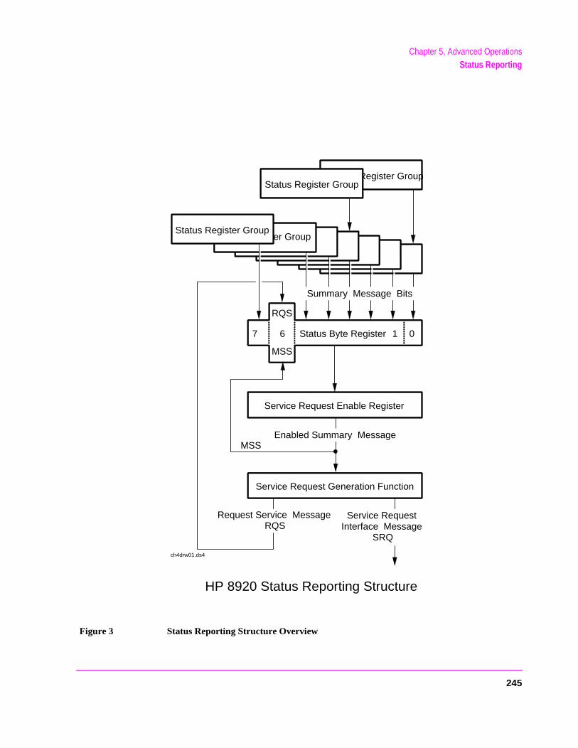
Chapter 5, Advanced OperationsStatus Reporting
Figure 3 Status Reporting Structure Overview
Status Register GroupStatus Register Group
Status Register GroupStatus Register Group
RQS
MSS
6 Status Byte Register 1 07
Service Request Enable Register
Service Request Generation Function
MSS
HP 8920 Status Reporting Structure
Service RequestInterface Message
SRQ
Enabled Summary Message
Request Service Message RQS
ch4drw01.ds4
Summary Message Bits
245
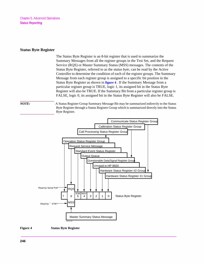
Chapter 5, Advanced OperationsStatus Reporting
Status Byte Register
The Status Byte Register is an 8-bit register that is used to summarize the Summary Messages from all the register groups in the Test Set, and the Request Service (RQS) or Master Summary Status (MSS) messages. The contents of the Status Byte Register, referred to as the status byte, can be read by the Active Controller to determine the condition of each of the register groups. The Summary Message from each register group is assigned to a specific bit position in the Status Byte Register as shown in figure 4 . If the Summary Message from a particular register group is TRUE, logic 1, its assigned bit in the Status Byte Register will also be TRUE. If the Summary Bit from a particular register group is FALSE, logic 0, its assigned bit in the Status Byte Register will also be FALSE.
NOTE: A Status Register Group Summary Message Bit may be summarized indirectly to the StatusByte Register through a Status Register Group which is summarized directly into the StatusByte Register.
Figure 4 Status Byte Register
Communicate Status Register Group
Operation Status Register Group
Request Service Message
Standard Event Status Register
Output Queue
Questionable Data/Signal Register Group
Unused in HP 8920
Hardware Status Register #2 Group
Calibration Status Register Group
RQS
MSS
6 1 07
Master Summary Status Message
Status Byte Register
Hardware Status Register #1 Group
Read by Serial Poll
Read by STB?
Call Processing Status Register Group
5 4 3 2ESB MAV
ch4drw2.ds4
246
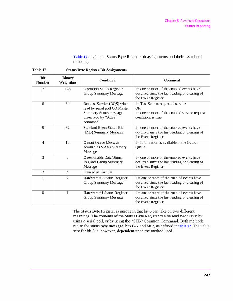
Chapter 5, Advanced OperationsStatus Reporting
Table 17 details the Status Byte Register bit assignments and their associated meaning.
The Status Byte Register is unique in that bit 6 can take on two different meanings. The contents of the Status Byte Register can be read two ways: by using a serial poll, or by using the *STB? Common Command. Both methods return the status byte message, bits 0-5, and bit 7, as defined in table 17. The value sent for bit 6 is, however, dependent upon the method used.
Table 17 Status Byte Register Bit Assignments
Bit Number
Binary Weighting
Condition Comment
7 128 Operation Status Register Group Summary Message
1= one or more of the enabled events have occurred since the last reading or clearing of the Event Register
6 64 Request Service (RQS) when read by serial poll OR Master Summary Status message when read by *STB? command
1= Test Set has requested serviceOR 1= one or more of the enabled service request conditions is true
5 32 Standard Event Status Bit (ESB) Summary Message
1= one or more of the enabled events have occurred since the last reading or clearing of the Event Register
4 16 Output Queue Message Available (MAV) Summary Message
1= information is available in the Output Queue
3 8 Questionable Data/Signal Register Group Summary Message
1= one or more of the enabled events have occurred since the last reading or clearing of the Event Register
2 4 Unused in Test Set
1 2 Hardware #2 Status Register Group Summary Message
1 = one or more of the enabled events have occurred since the last reading or clearing of the Event Register
0 1 Hardware #1 Status Register Group Summary Message
1 = one or more of the enabled events have occurred since the last reading or clearing of the Event Register
247

Chapter 5, Advanced OperationsStatus Reporting
t 64). l to
8.2-l
ble,
Reading with a Serial Poll
The contents of the Status Byte Register can be read by a serial poll from the Active Controller in response to some device on the bus sending the Service Request (SRQ) message. When read with a serial poll, bit 6 in the Status Byte Register represents the Request Service (RQS) condition. Bit 6 is TRUE, logic 1, if the Test Set is sending the Service Request (SRQ) message and FALSE, logic 0, if it is not. Bits 0-5 and bit 7 are defined as shown in table 17 on page 247. When read by a serial poll the RQS bit is cleared (set to 0) so that the RQS message will be FALSE if the Test Set is polled again before a new reason for requesting service has occurred. Bits 0-5 and bit 7 are unaffected by a serial poll.
Reading with the *STB? Common Command
The contents of the Status Byte Register can be read by the application program using the *STB? Common Command. When read with the *STB? Common Command, bit 6 represents the Master Summary Status (MSS) message. The MSS message is the inclusive OR of the bitwise combination (excluding bit 6) of the Status Byte Register and the Service Request Enable Register. For a discussion of Summary Messages, see "Status Register Structure Overview" on page 250. Bit 6 is TRUE, logic 1, if the Test Set has at least one reason for requesting service and FALSE, logic 0, if it does not. Bits 0-5 and bit 7 are defined as shown in table 17 on page 247. When read by the *STB? Common Command, bits 0-5, bit 6, and bit 7 are unaffected
The *STB? Status Byte Query allows the programmer to determine the current contents (bit pattern) of the Status Byte Register and the Master Summary Status (MSS) message as a single element. The Test Set responds to the *STB? query by placing the binary-weighted decimal value of the Status Byte Register and the MSS message into the Output Queue. The response represents the sum of the binary-weighted values of the Status Byte Register’s bits 0-5 and 7 (weights 1,2,4,8,16,32 and 128 respectively) and the MSS summary message (weighThus, the response to *STB?, when considered as a binary value, is identicathe response to a serial poll except that the MSS message of 1 indicates that the Test Set has at least one reason for requesting service (Refer to the IEEE 481987 Standard for a complete description of the MSS message). The decimavalue of the bit pattern will be a positive integer in the range of 0 to 255. Theresponse data is obtained by reading the Output Queue into a numeric variainteger or real.
248
Chapter 5, Advanced OperationsStatus Reporting
Example BASIC program to read Status Byte with *STB command10 INTEGER Stat_byte_reg,Stat_byte,Mstr_sum_msg20 OUTPUT 714;"*STB?"30 ENTER 714;Stat_byte_reg40 Stat_byte=BINAND(Stat_byte_reg,191) !mask out the MSS bit50 PRINT Stat_byte60 Mstr_sum_msg=BINAND(Stat_byte_reg,64) !mask out the Stat
Byte70 PRINT Mstr_sum_msg80 END
Example response320
Writing the Status Byte Register
The Status Byte Register is a read-only register and is altered only when the state of the Summary Messages from the overlaying data structures are altered.
Clearing the Status Byte Register
The *CLS Common Command clears all Event Registers and Queues so that their corresponding Summary Messages are cleared. The Output Queue and its MAV Summary Message are an exception and are unaffected by the *CLS Common Command.
249
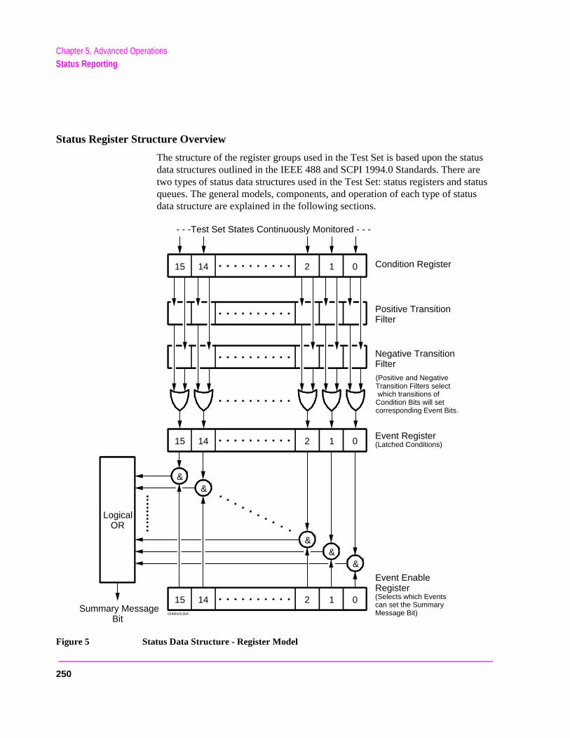
Chapter 5, Advanced OperationsStatus Reporting
Status Register Structure Overview
The structure of the register groups used in the Test Set is based upon the status data structures outlined in the IEEE 488 and SCPI 1994.0 Standards. There are two types of status data structures used in the Test Set: status registers and status queues. The general models, components, and operation of each type of status data structure are explained in the following sections.
Figure 5 Status Data Structure - Register Model
- - -Test Set States Continuously Monitored - - -
15 14 2 01
15 14 2 01
15 14 2 01
&
LogicalOR
Summary MessageBit
Event EnableRegister(Selects which Eventscan set the SummaryMessage Bit)
Event Register(Latched Conditions)
Positive TransitionFilter
Negative TransitionFilter(Positive and NegativeTransition Filters select which transitions ofCondition Bits will setcorresponding Event Bits.)
Condition Register
&
&&
&
ch4drw3.ds4
250

Chapter 5, Advanced OperationsStatus Reporting
Status Register Model
This section explains how the status registers are structured in the Test Set. The generalized status register model shown in figure 5 on page 250 is the basis upon which all the status registers in the Test Set are built. The model consists of a Condition Register, Transition Filters, an Event Register, an Enable Register, and a Summary Message. A set of these registers is called a Status Register Group.
Condition Register. A condition is a Test Set state that is either TRUE or FALSE (an HP-IB command error has occurred or an HP-IB command error has not occurred). Each bit in a Condition Register is assigned to a particular Test Set state. A Condition Register continuously monitors the hardware and firmware states assigned to it. There is no latching or buffering of any bits in a Condition Register; it is updated in real time. Condition Registers are read-only. Condition Registers in the Test Set are 16 bits long and may contain unused bits. All unused bits return a zero value when read.
Transition Filters. For each bit in the Condition Register, the Transition Filters determine which of two bit-state transitions will set the corresponding bit in the Event Register. Transition Filters may be set to pass positive transitions (PTR), negative transitions (NTR) or either (PTR or NTR). A positive transition means a condition bit changed from 0 to 1. A negative transition means a condition bit changed from 1 to 0.
In the Test Set, the Transition Filters are implemented as two registers: a 16-bit positive transition (PTR) register and a 16-bit negative transition (NTR) register. A positive transition of a bit in the Condition register will be latched in the Event Register if the corresponding bit in the positive transition filter is set to 1. A positive transition of a bit in the Condition register will not be latched in the Event Register if the corresponding bit in the positive transition filter is set to 0. A negative transition of a bit in the Condition register will be latched in the Event Register if the corresponding bit in the negative transition filter is set to 1. A negative transition of a bit in the Condition register will not be latched in the Event Register if the corresponding bit in the negative transition filter is set to 0. Either transition (PTR or NTR) of a bit in the Condition Register will be latched in the Event Register if the corresponding bit in both transition filters is set to 1. No transitions (PTR or NTR) of a bit in the Condition Register will be latched in the Event Register if the corresponding bit in both transition filters is set to 0.
251

Chapter 5, Advanced OperationsStatus Reporting
n itions rs may
nt ble s an sing mary roup are sed n CLS
ce the
se of mary
y the hen
n
Transition Filters are read-write. Transition Filters are unaffected by a *CLS (clear status) command or queries. The Transitions Filters are set to pass positive transitions (PTR) at power on and after receiving the *RST (reset) command (all 16 bits of the PTR register set to 1 and all 16 bits of the NTR register set to 0).
Event Register. The Event Register captures bit-state transitions in the Condition Register as defined by the Transition Filters. Each bit in the Event Register corresponds to a bit in the Condition Register, or if there is no Condition Register/Transition Filter combination, each bit corresponds to a specific condition in the Test Set. Bits in the Event Register are latched, and, once set, they remain set until cleared by a query of the Event Register or a *CLS (clear status) command. This guarantees that the application can’t miss a bit-state transition in the ConditioRegister. There is no buffering; so while an event bit is set, subsequent transin the Condition Register corresponding to that bit are ignored. Event Registeare read-only. Event Registers in the Test Set are either 8 or 16 bits long andcontain unused bits. All unused bits return a zero value when read.
Event Enable Register. The Event Enable Register defines which bits in the EveRegister will be used to generate the Summary Message. Each bit in the EnaRegister has a corresponding bit in the Event Register. The Test Set logicallyANDs corresponding bits in the Event and Enable registers and then performinclusive OR on all the resulting bits to generate the Summary Message. By uthe enable bits the application program can direct the Test Set to set the SumMessage to the 1 or TRUE state for a single event or an inclusive OR of any gof events. Enable Registers are read-write. Enable Registers in the Test Set either 8 or 16 bits long and may contain unused bits which correspond to unubits in the associated Event Register. All unused bits return a zero value wheread and are ignored when written to. Enable Registers are unaffected by a *(clear status) command or queries.
Summary Message Bit. The Summary Message is a single-bit message which indicates whether or not one or more of the enabled events have occurred sinlast reading or clearing of the Event Register. The Test Set logically ANDs corresponding bits in the Event and Enable registers and then performs an inclusive OR on all the resulting bits to generate the Summary Message. By uthe enable bits, the application program can direct the Test Set to set the SumMessage to the 1, or TRUE, state for a single event or an inclusive OR of angroup of events. The Summary Message is TRUE when an enabled event inEvent Register is set TRUE. Conversely, the Summary Message is FALSE wno enabled events are TRUE. Summary Messages are always seen as bits ianother register.
252
Chapter 5, Advanced OperationsStatus Reporting
ter,
as
he
he
Status Reporting Structure Operation.
In general the status reporting structure described on the previous pages is used as follows:
• Determine which conditions, as defined by their bit positions in the Condition Regisshould cause the Summary Message to be set TRUE if they occur.
For example, Condition Register Bit 3 = Overpower Protection Tripped • Determine the polarity of the bit-state transition which will indicate the condition h
occurred. For example,
logic 0 = Overpower Protection not tripped logic 1 = Overpower Protection tripped occurrence indicated by a 0 to 1 transition use positive transition (PTR) filter for bit 3
• Set the Transition Filters to the correct polarity to pass the bit-state transition to tEvent Register.
For example,Set Positive Transition Filter bit 3 to 1, all other bits to 0.Set Negative Transition Filter bit 3 to 0, all other bits to 0.
• Set the correct bits in the Enable Register to generate the Summary Message if tcondition has been latched into the Event Register.
For example,Set bit 3 of the Enable Register to a logic 1, all other bits to 0.
• Repeat these steps for any register containing the Summary Message bit.
253
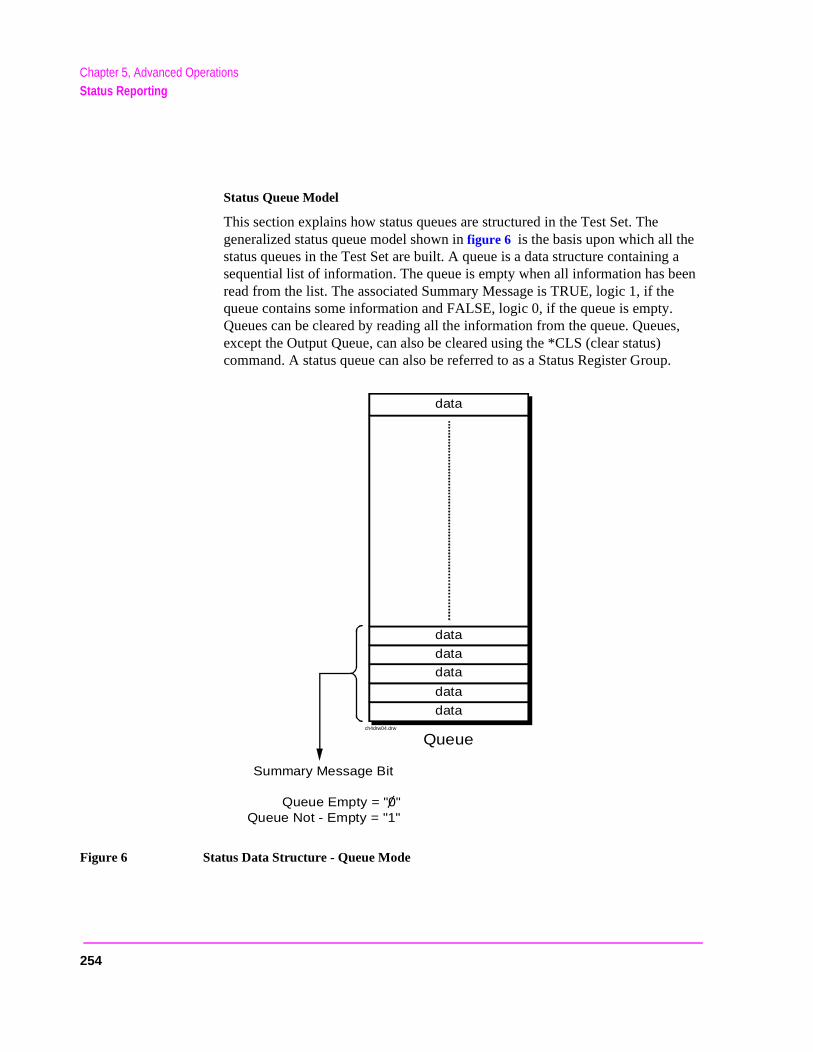
Chapter 5, Advanced OperationsStatus Reporting
Status Queue Model
This section explains how status queues are structured in the Test Set. The generalized status queue model shown in figure 6 is the basis upon which all the status queues in the Test Set are built. A queue is a data structure containing a sequential list of information. The queue is empty when all information has been read from the list. The associated Summary Message is TRUE, logic 1, if the queue contains some information and FALSE, logic 0, if the queue is empty. Queues can be cleared by reading all the information from the queue. Queues, except the Output Queue, can also be cleared using the *CLS (clear status) command. A status queue can also be referred to as a Status Register Group.
Figure 6 Status Data Structure - Queue Mode
data
Summary Message Bit
Queue Empty = "0"Queue Not - Empty = "1"
ch4drw04.drw
Queue
data
data
data
data
data
254
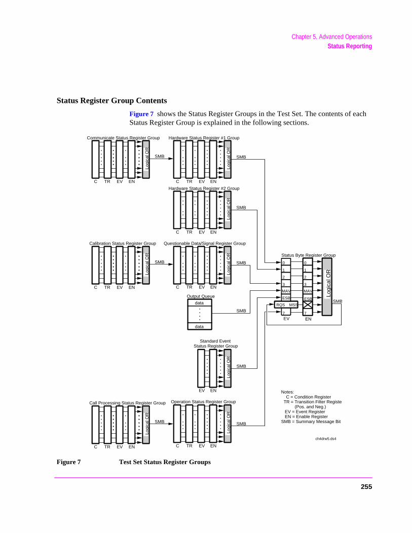
Chapter 5, Advanced OperationsStatus Reporting
Status Register Group Contents
Figure 7 shows the Status Register Groups in the Test Set. The contents of each Status Register Group is explained in the following sections.
Figure 7 Test Set Status Register Groups
0
1
2
3
MAV
ESB
7
RQS MSS
0
1
2
3
MAV
ESB
7
Logi
cal O
R
Logi
cal O
R
Hardware Status Register #1 Group
Logi
cal O
R
Hardware Status Register #2 Group
Logi
cal O
R
Questionable Data/Signal Register Group
Logi
cal O
R
Standard EventStatus Register Group
Logi
cal O
R
Operation Status Register Group
Logi
cal O
R
Communicate Status Register Group
Logi
cal O
R
Calibration Status Register Group
C TR EV EN
SMB
C TR EV EN
C TR EV EN
EV EN
EV EN
data
data
Output Queue
SMB
Status Byte Register Group
SMB
SMB
SMB
SMB
SMB
SMB
SMB
Notes: C = Condition Register TR = Transition Filter Register (Pos. and Neg.) EV = Event Register EN = Enable RegisterSMB = Summary Message Bit
C TR EV EN
C TR EV ENC TR EV EN
ch4drw5.ds4
Logi
cal O
R
Call Processing Status Register Group
SMB
C TR EV EN
255
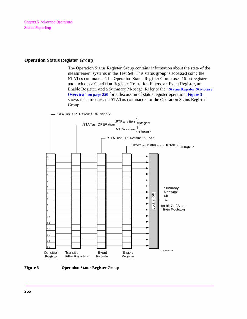
Chapter 5, Advanced OperationsStatus Reporting
Operation Status Register Group
The Operation Status Register Group contains information about the state of the measurement systems in the Test Set. This status group is accessed using the STATus commands. The Operation Status Register Group uses 16-bit registers and includes a Condition Register, Transition Filters, an Event Register, an Enable Register, and a Summary Message. Refer to the "Status Register Structure Overview" on page 250 for a discussion of status register operation. Figure 8 shows the structure and STATus commands for the Operation Status Register Group.
Figure 8 Operation Status Register Group
0
:STATus: OPERation: ENABle?<integer>
:STATus: OPERation: EVENt ?
:STATus: OPERation:PTRansition
:NTRansition
?<integer>?<integer>
:STATus: OPERation: CONDition ?
SummaryMessageBit
ConditionRegister
TransitionFilter Registers
EventRegister
EnableRegister
1
2
3
4
5
6
7
8
9
10
11
12
13
14
Lo
gica
l OR
15
(to bit 7 of Status Byte Register)
ch4drw06.drw
256
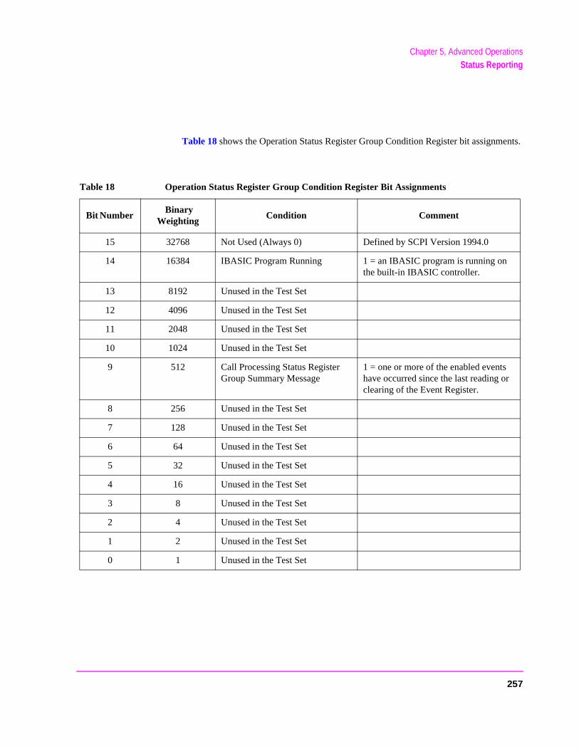
Chapter 5, Advanced OperationsStatus Reporting
Table 18 shows the Operation Status Register Group Condition Register bit assignments.
Table 18 Operation Status Register Group Condition Register Bit Assignments
Bit Number Binary
Weighting Condition Comment
15 32768 Not Used (Always 0) Defined by SCPI Version 1994.0
14 16384 IBASIC Program Running 1 = an IBASIC program is running on the built-in IBASIC controller.
13 8192 Unused in the Test Set
12 4096 Unused in the Test Set
11 2048 Unused in the Test Set
10 1024 Unused in the Test Set
9 512 Call Processing Status Register Group Summary Message
1 = one or more of the enabled events have occurred since the last reading or clearing of the Event Register.
8 256 Unused in the Test Set
7 128 Unused in the Test Set
6 64 Unused in the Test Set
5 32 Unused in the Test Set
4 16 Unused in the Test Set
3 8 Unused in the Test Set
2 4 Unused in the Test Set
1 2 Unused in the Test Set
0 1 Unused in the Test Set
257
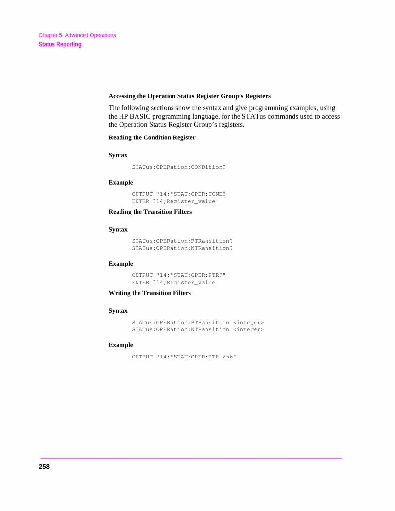
Chapter 5, Advanced OperationsStatus Reporting
Accessing the Operation Status Register Group’s Registers
The following sections show the syntax and give programming examples, using the HP BASIC programming language, for the STATus commands used to access the Operation Status Register Group’s registers.
Reading the Condition Register
Syntax
STATus:OPERation:CONDition?
Example
OUTPUT 714;"STAT:OPER:COND?"ENTER 714;Register_value
Reading the Transition Filters
Syntax
STATus:OPERation:PTRansition?STATus:OPERation:NTRansition?
Example
OUTPUT 714;"STAT:OPER:PTR?"ENTER 714;Register_value
Writing the Transition Filters
Syntax
STATus:OPERation:PTRansition <integer>STATus:OPERation:NTRansition <integer>
Example
OUTPUT 714;"STAT:OPER:PTR 256"
258

Chapter 5, Advanced OperationsStatus Reporting
Reading the Event Register
Syntax
STATus:OPERation:EVENt?
Example
OUTPUT 714;"STAT:OPER:EVEN?"ENTER 714;Register_value
Clearing the Event Register
The EVENT register is cleared whenever it is queried or whenever the Common Command *CLS is sent to the Test Set.
Reading the Enable Register
Syntax
STATus:OPERation:ENABle?
Example
OUTPUT 714;"STAT:OPER:ENAB?"ENTER 714;Register_value
Writing the Enable Register
Syntax
STATus:OPERation:ENABle <integer>
Example
OUTPUT 714;"STAT:OPER:ENAB 256"
Clearing the Enable Register
The ENABLE register is cleared by writing to it with an integer value of zero.
259
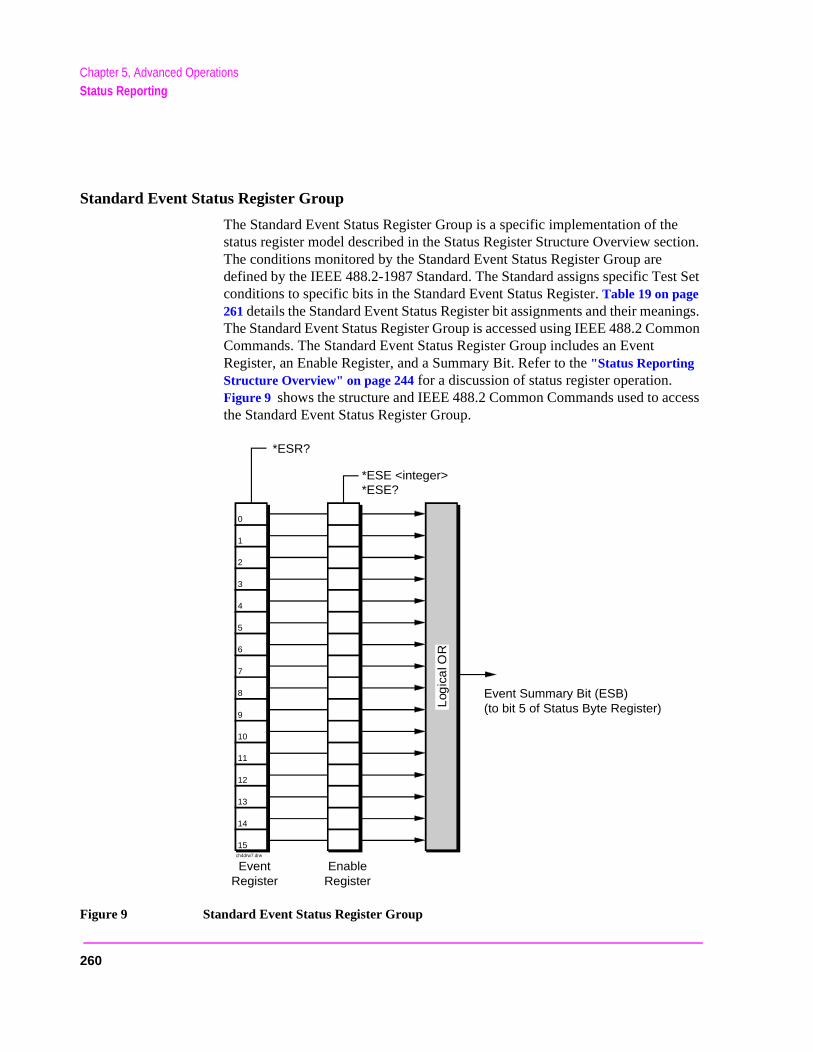
Chapter 5, Advanced OperationsStatus Reporting
Standard Event Status Register Group
The Standard Event Status Register Group is a specific implementation of the status register model described in the Status Register Structure Overview section. The conditions monitored by the Standard Event Status Register Group are defined by the IEEE 488.2-1987 Standard. The Standard assigns specific Test Set conditions to specific bits in the Standard Event Status Register. Table 19 on page 261 details the Standard Event Status Register bit assignments and their meanings. The Standard Event Status Register Group is accessed using IEEE 488.2 Common Commands. The Standard Event Status Register Group includes an Event Register, an Enable Register, and a Summary Bit. Refer to the "Status Reporting Structure Overview" on page 244 for a discussion of status register operation. Figure 9 shows the structure and IEEE 488.2 Common Commands used to access the Standard Event Status Register Group.
Figure 9 Standard Event Status Register Group
*ESE <integer>*ESE?
*ESR?
Event Summary Bit (ESB)(to bit 5 of Status Byte Register)
EventRegister
EnableRegister
Log
ica
l OR
0
1
2
3
4
5
6
7
8
9
10
11
12
13
14
15ch4drw7.drw
260
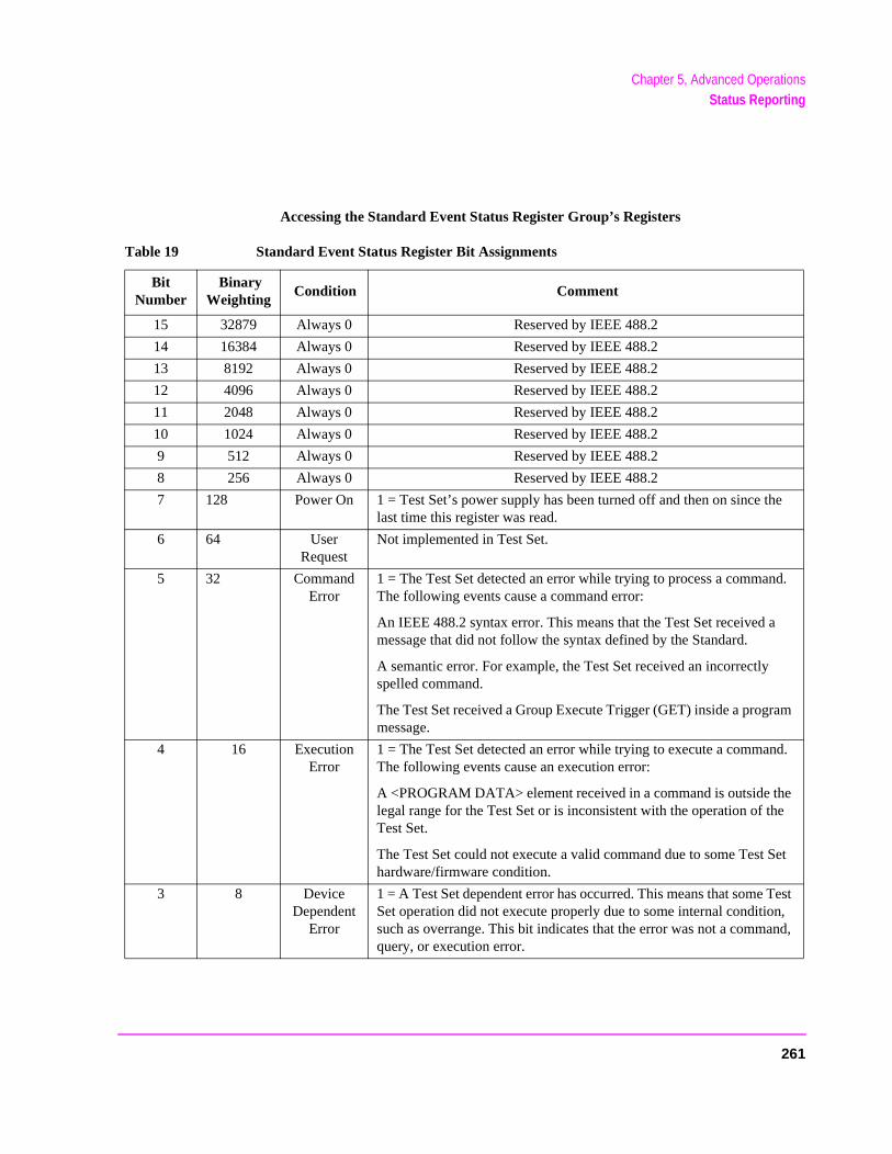
Chapter 5, Advanced OperationsStatus Reporting
e
d.
m
d.
et
est , d,
Accessing the Standard Event Status Register Group’s Registers
Table 19 Standard Event Status Register Bit Assignments
Bit Number
Binary Weighting
Condition Comment
15 32879 Always 0 Reserved by IEEE 488.2
14 16384 Always 0 Reserved by IEEE 488.2
13 8192 Always 0 Reserved by IEEE 488.2
12 4096 Always 0 Reserved by IEEE 488.2
11 2048 Always 0 Reserved by IEEE 488.2
10 1024 Always 0 Reserved by IEEE 488.2
9 512 Always 0 Reserved by IEEE 488.2
8 256 Always 0 Reserved by IEEE 488.2
7 128 Power On 1 = Test Set’s power supply has been turned off and then on since thlast time this register was read.
6 64 User Request
Not implemented in Test Set.
5 32 Command Error
1 = The Test Set detected an error while trying to process a commanThe following events cause a command error:
An IEEE 488.2 syntax error. This means that the Test Set received amessage that did not follow the syntax defined by the Standard.
A semantic error. For example, the Test Set received an incorrectly spelled command.
The Test Set received a Group Execute Trigger (GET) inside a programessage.
4 16 Execution Error
1 = The Test Set detected an error while trying to execute a commanThe following events cause an execution error:
A <PROGRAM DATA> element received in a command is outside thelegal range for the Test Set or is inconsistent with the operation of theTest Set.
The Test Set could not execute a valid command due to some Test Shardware/firmware condition.
3 8 Device Dependent
Error
1 = A Test Set dependent error has occurred. This means that some TSet operation did not execute properly due to some internal conditionsuch as overrange. This bit indicates that the error was not a commanquery, or execution error.
261
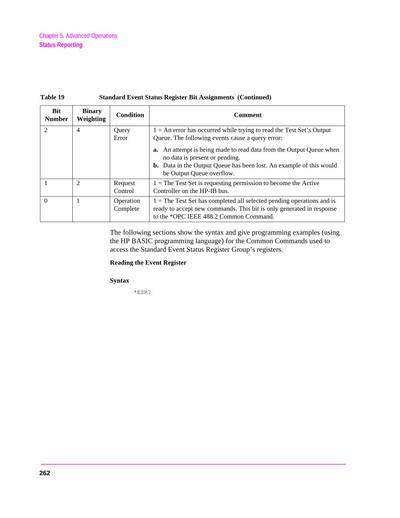
Chapter 5, Advanced OperationsStatus Reporting
n
is e
The following sections show the syntax and give programming examples (using the HP BASIC programming language) for the Common Commands used to access the Standard Event Status Register Group’s registers.
Reading the Event Register
Syntax
*ESR?
2 4 Query Error
1 = An error has occurred while trying to read the Test Set’s Output Queue. The following events cause a query error:
a. An attempt is being made to read data from the Output Queue wheno data is present or pending.
b. Data in the Output Queue has been lost. An example of this wouldbe Output Queue overflow.
1 2 Request Control
1 = The Test Set is requesting permission to become the Active Controller on the HP-IB bus.
0 1 Operation Complete
1 = The Test Set has completed all selected pending operations and ready to accept new commands. This bit is only generated in responsto the *OPC IEEE 488.2 Common Command.
Table 19 Standard Event Status Register Bit Assignments (Continued)
Bit Number
Binary Weighting
Condition Comment
262
Chapter 5, Advanced OperationsStatus Reporting
Example
OUTPUT 714;"*ESR?"ENTER 714;Register_value
The *ESR? query allows the programmer to determine the current contents (bit pattern) of the Standard Event Status Register. The Test Set responds to the *ESR? query by placing the binary-weighted decimal value of the Standard Event Status Register bit pattern into the Output Queue. The decimal value of the bit pattern will be a positive integer in the range of 0 to 255. The response data is obtained by reading the Output Queue into a numeric variable, integer or real. Reading the Standard Event Status Register clears it (sets all bits to zero).
Example BASIC program
10 INTEGER Std_evn_stat_rg20 OUTPUT 714;"*ESR?"30 ENTER 714;Std_evn_stat_rg40 PRINT Std_evn_stat_rg50 END
Example response
32
Clearing the Event Register
The EVENT register is cleared whenever it is queried or whenever the *CLS Common Command is sent to the Test Set.
263
Chapter 5, Advanced OperationsStatus Reporting
Reading the Enable Register
Syntax
*ESE?
Example
OUTPUT 714;"*ESE?"ENTER 714;Register_value
The *ESE? query allows the programmer to determine the current contents (bit pattern) of the Standard Event Status Enable Register. The Test Set responds to the *ESE? query by placing the binary-weighted decimal value of the Standard Event Status Enable Register bit pattern into the Output Queue. The decimal value of the bit pattern will be a positive integer in the range of 0 to 255. The response data is obtained by reading the Output Queue into a numeric variable, integer or real.
Example BASIC program
10 INTEGER Std_evn_enab_rg20 OUTPUT 714;"ESE?"30 ENTER 714;Std_evn_enab_rg40 PRINT Std_evn_enab_rg50 END
Example response
36
264
Chapter 5, Advanced OperationsStatus Reporting
Writing the Enable Register
Syntax
*ESE <integer>
Example
OUTPUT 714;"*ESE 255"
The *ESE command sets the bit pattern (bits 0 through 7) of the Standard Event Status Enable Register. The Standard Event Status Enable Register allows the programmer to indicate the occurrence of one or more events (as defined by bits 0 through 7 of the Standard Event Status Register) in bit 5 of the Status Byte Register.
The bit pattern set by the *ESE command is determined by selecting the desired event(s) from the Standard Event Status Register, setting the value of the bit position(s) to a logical one, setting the value of all non-selected bit positions to a logical zero, and sending the binary-weighted decimal equivalent of bits 0 through 7 after the *ESE command. For example, if the programmer wished to have the occurrence of a Command Error (bit position 5 in the Standard Event Status Register) and the occurrence of a Query Error (bit position 2 in the Standard Event Status Register) to be reflected in bit 5 of the Status Byte Register, the binary-weighted decimal value of the bit pattern for the Standard Event Status Enable Register would be determined as follows:
Example
OUTPUT 714;"*ESE 36"
The decimal value of the bit pattern must be a positive integer in the range of 0 to 255. Sending a negative number or a number greater than 255 causes an HP-IB Error: -222 Data out of range.
Clearing the Enable Register
The ENABLE register is cleared by writing to it with an integer value of zero.
Bit Position 7 6 5 4 3 2 1 0
Logical Value 0 0 1 0 0 1 0 0
Binary Weighting
128 64 32 16 8 4 2 1
Decimal Value 0 +0 +32 +0 +0 +4 +0 +0 = 36
265
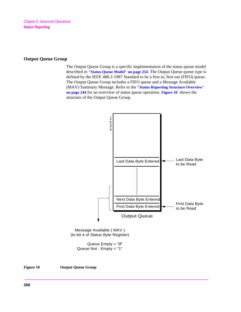
Chapter 5, Advanced OperationsStatus Reporting
Output Queue Group
The Output Queue Group is a specific implementation of the status queue model described in "Status Queue Model" on page 254. The Output Queue queue type is defined by the IEEE 488.2-1987 Standard to be a first in, first out (FIFO) queue. The Output Queue Group includes a FIFO queue and a Message Available (MAV) Summary Message. Refer to the "Status Reporting Structure Overview" on page 244 for an overview of status queue operation. Figure 10 shows the structure of the Output Queue Group.
Figure 10 Output Queue Group
Last Data Byte Entered
Next Data Byte Entered
First Data Byte Entered
Last Data Byteto be Read
First Data Byteto be Read
Message Available ( MAV )(to bit 4 of Status Byte Register)
Queue Empty = "0"Queue Not - Empty = "1"
Output Queue
266

Chapter 5, Advanced OperationsStatus Reporting
Set’s ds
d in
sage , LK
he
ling t fore
Accessing the Output Queue
When messages are sent to the Test Set, it decodes the message to determine what commands have been sent. Depending upon the type of command, the Testprocessor sends messages to various parts of the instrument. Many commangenerate data which must be sent back to the controller. This data is bufferethe Output Queue until it is read by the controller. The availability of data is summarized in the MAV bit of the Status Byte Register. The state of the MAVmessage indicates whether or not the Output Queue is empty. The MAV mesis TRUE, logic 1, when there is data in the Output Queue and FALSE, logic 0when it is empty. The Output Queue is read by addressing the Test Set to TAand then handshaking the bytes out of the Output Queue. Depending upon ttype of command sent, the data may appear in the Output Queue almost immediately, or it may take several seconds (as is the case with some SignaDecoder measurements). Care should be exercised when reading the OutpuQueue since the HP-IB bus will, by design, wait until the data is available beprocessing further bus messages.
Reading the Output Queue
Example
Enter 714;Output_data
267
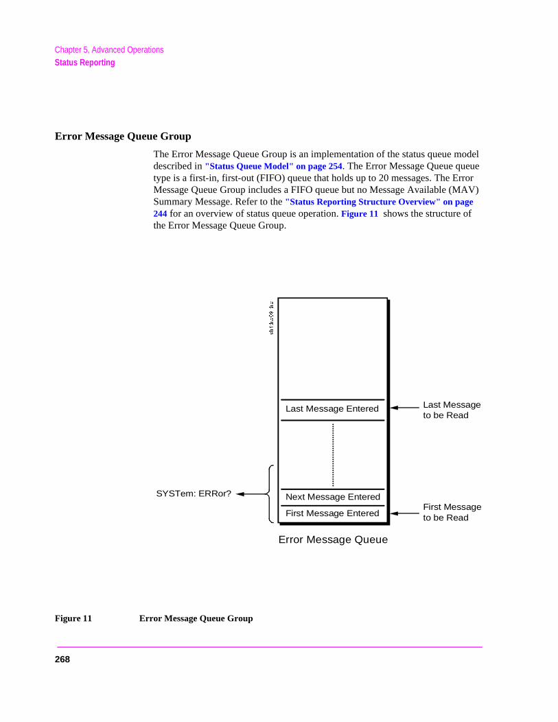
Chapter 5, Advanced OperationsStatus Reporting
Error Message Queue Group
The Error Message Queue Group is an implementation of the status queue model described in "Status Queue Model" on page 254. The Error Message Queue queue type is a first-in, first-out (FIFO) queue that holds up to 20 messages. The Error Message Queue Group includes a FIFO queue but no Message Available (MAV) Summary Message. Refer to the "Status Reporting Structure Overview" on page 244 for an overview of status queue operation. Figure 11 shows the structure of the Error Message Queue Group.
Figure 11 Error Message Queue Group
Last Message Entered
Next Message Entered
First Message Entered
Last Messageto be Read
First Messageto be Read
SYSTem: ERRor?
Error Message Queue
268
Chapter 5, Advanced OperationsStatus Reporting
Accessing the Error Message Queue
A message appears in the Error Message Queue any time bit 2, 3, 4, or 5 of the Standard Event Status register is asserted. Each message consists of a signed error number, followed by a comma separator, followed by an error description string in double quotes. The maximum length of the error description string is 255 characters. If more than 20 messages are in the queue and another error occurs, the last message is replaced with the message, -350,"Queue overflow". If no messages are in the queue the message, +0,"No error" is returned. Reading a message removes it from the queue. The Error Message Queue is accessed using the SYSTem command. Returned information is read into a numeric variable followed by a string variable.
Reading the Error Message Queue
Syntax
SYSTem:ERRor?
Example
OUTPUT 714;"SYST:ERR?"ENTER 714;Error_num,Error_msg$
Example IBASIC program
10 INTEGER Error_num20 DIM Error_msg$ [255] 30 OUTPUT 714;"SYST:ERR?"40 ENTER 714;Error_num,Error_msg$50 PRINT Error_num;Error_msg$60 END
Example response
-113 "Undefined header"
269
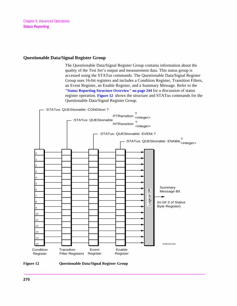
Chapter 5, Advanced OperationsStatus Reporting
ister ers, he
e
Questionable Data/Signal Register Group
The Questionable Data/Signal Register Group contains information about the quality of the Test Set’s output and measurement data. This status group is accessed using the STATus commands. The Questionable Data/Signal RegGroup uses 16-bit registers and includes a Condition Register, Transition Filtan Event Register, an Enable Register, and a Summary Message. Refer to t"Status Reporting Structure Overview" on page 244 for a discussion of status register operation. Figure 12 shows the structure and STATus commands for thQuestionable Data/Signal Register Group.
Figure 12 Questionable Data/Signal Register Group
0
:STATus: QUEStionable: ENABle?<integer>
:STATus: QUEStionable: EVENt ?
:STATus: QUEStionable:PTRansition
:NTRansition
?<integer>
?<integer>
:STATus: QUEStionable: CONDition ?
SummaryMessage Bit
ConditionRegister
TransitionFilter Registers
EventRegister
EnableRegister
1
2
3
4
5
6
7
8
9
10
11
12
13
14
Log
ical
OR
15 ch4drw10.drw
(to bit 3 of StatusByte Register)
270
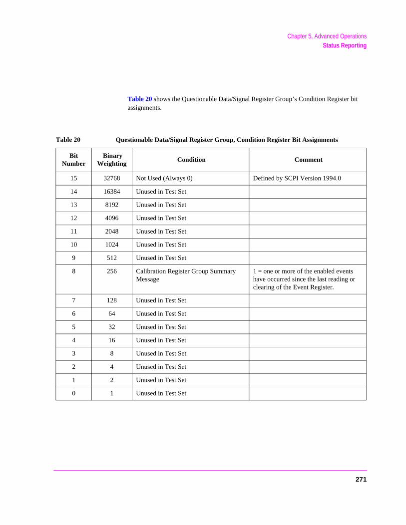
Chapter 5, Advanced OperationsStatus Reporting
it
Table 20 shows the Questionable Data/Signal Register Group’s Condition Register bassignments.Table 20 Questionable Data/Signal Register Group, Condition Register Bit Assignments
Bit Number
Binary Weighting
Condition Comment
15 32768 Not Used (Always 0) Defined by SCPI Version 1994.0
14 16384 Unused in Test Set
13 8192 Unused in Test Set
12 4096 Unused in Test Set
11 2048 Unused in Test Set
10 1024 Unused in Test Set
9 512 Unused in Test Set
8 256 Calibration Register Group Summary Message
1 = one or more of the enabled events have occurred since the last reading or clearing of the Event Register.
7 128 Unused in Test Set
6 64 Unused in Test Set
5 32 Unused in Test Set
4 16 Unused in Test Set
3 8 Unused in Test Set
2 4 Unused in Test Set
1 2 Unused in Test Set
0 1 Unused in Test Set
271

Chapter 5, Advanced OperationsStatus Reporting
Accessing the Questionable Data/Signal Register Group’s Registers
The following sections show the syntax and give programming examples (using the HP BASIC programming language) for the STATus commands used to access the Questionable Data/Signal Register Group’s registers.
Reading the Condition Register
Syntax
STATus:QUEStionable:CONDition?
Example
OUTPUT 714;"STAT:QUES:COND?"ENTER 714;Register_value
Reading the Transition Filters
Syntax
STATus:QUEStionable:PTRansition?STATus:QUEStionable:NTRansition?
Example
OUTPUT 714;"STAT:QUES:PTR?"ENTER 714;Register_value
Writing the Transition Filters
Syntax
STATus:QUEStionable:PTRansition <integer>STATus:QUEStionable:NTRansition <integer>
Example
OUTPUT 714;"STAT:QUES:PTR 256"
272

Chapter 5, Advanced OperationsStatus Reporting
Reading the Event Register
Syntax
STATus:QUEStionable:EVENt?
Example
OUTPUT 714;"STAT:QUES:EVEN?"ENTER 714;Register_value
Clearing the Event Register
The EVENT register is cleared whenever it is queried or whenever the Common Command *CLS is sent to the Test Set.
Reading the Enable Register
Syntax
STATus:QUEStionable:ENABle?
Example
OUTPUT 714;"STAT:QUES:ENAB?"ENTER 714;Register_value
Writing the Enable Register
Syntax
STATus:QUEStionable:ENABle <integer>
Example
OUTPUT 714;"STAT:QUES:ENAB 256"
Clearing the Enable Register
The ENABLE register is cleared by writing to it with an integer value of zero.
273
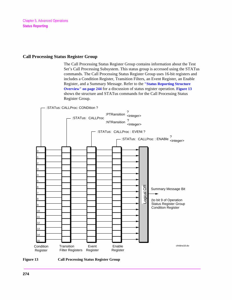
Chapter 5, Advanced OperationsStatus Reporting
ATus and le
Call Processing Status Register Group
The Call Processing Status Register Group contains information about the Test Set’s Call Processing Subsystem. This status group is accessed using the STcommands. The Call Processing Status Register Group uses 16-bit registersincludes a Condition Register, Transition Filters, an Event Register, an EnabRegister, and a Summary Message. Refer to the "Status Reporting Structure Overview" on page 244 for a discussion of status register operation. Figure 13 shows the structure and STATus commands for the Call Processing Status Register Group.
Figure 13 Call Processing Status Register Group
0
:STATus: CALLProc : ENABle?<integer>
:STATus: CALLProc : EVENt ?
:STATus: CALLProc:PTRansition
:NTRansition
?<integer>?<integer>
:STATus: CALLProc: CONDition ?
Summary Message Bit
ConditionRegister
TransitionFilter Registers
EventRegister
EnableRegister
1
2
3
4
5
6
7
8
9
10
11
12
13
14
Logi
cal O
R
15
ch4drw18.ds4
(to bit 9 of OperationStatus Register GroupCondition Register
274
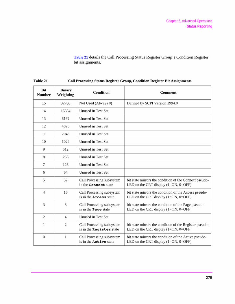
Chapter 5, Advanced OperationsStatus Reporting
ter
Table 21 details the Call Processing Status Register Group’s Condition Regisbit assignments.Table 21 Call Processing Status Register Group, Condition Register Bit Assignments
Bit Number
Binary Weighting
Condition Comment
15 32768 Not Used (Always 0) Defined by SCPI Version 1994.0
14 16384 Unused in Test Set
13 8192 Unused in Test Set
12 4096 Unused in Test Set
11 2048 Unused in Test Set
10 1024 Unused in Test Set
9 512 Unused in Test Set
8 256 Unused in Test Set
7 128 Unused in Test Set
6 64 Unused in Test Set
5 32 Call Processing subsystem in the Connect state
bit state mirrors the condition of the Connect pseudo-LED on the CRT display (1=ON, 0=OFF)
4 16 Call Processing subsystem is in the Access state
bit state mirrors the condition of the Access pseudo-LED on the CRT display (1=ON, 0=OFF)
3 8 Call Processing subsystem is in the Page state
bit state mirrors the condition of the Page pseudo-LED on the CRT display (1=ON, 0=OFF)
2 4 Unused in Test Set
1 2 Call Processing subsystem is in the Register state
bit state mirrors the condition of the Register pseudo-LED on the CRT display (1=ON, 0=OFF)
0 1 Call Processing subsystem is in the Active state
bit state mirrors the condition of the Active pseudo-LED on the CRT display (1=ON, 0=OFF)
275

Chapter 5, Advanced OperationsStatus Reporting
Accessing the Call Processing Status Register Group’s Registers
The following sections show the syntax and give programming examples (using the HP BASIC programming language) for the STATus commands used to access the Call Processing Status Register Group’s registers.
Reading the Condition Register
Syntax
STATus:CALLProc:CONDition?
Example
OUTPUT 714;"STAT:CALLP:COND?"ENTER 714;Register_value
Reading the Transition Filters
Syntax
STATus:CALLProc:PTRansition?STATus:CALLProc:NTRansition?
Example
OUTPUT 714;"STAT:CALLP:PTR?"ENTER 714;Register_value
Writing the Transition Filters
Syntax
STATus:CALLProc:PTRansition <integer>STATus:CALLProc:NTRansition <integer>
Example
OUTPUT 714;"STAT:CALLP:PTR 256"
276

Chapter 5, Advanced OperationsStatus Reporting
Reading the Event Register
Syntax
STATus:CALLProc:EVENt?
Example
OUTPUT 714;"STAT:CALLP:EVEN?"ENTER 714;Register_value
Clearing the Event Register
The EVENT register is cleared whenever it is queried or whenever the Common Command *CLS is sent to the Test Set.
Reading the Enable Register
Syntax
STATus:CALLProc:ENABle?
Example
OUTPUT 714;"STAT:CALLP:ENAB?"ENTER 714;Register_value
Writing the Enable Register
Syntax
STATus:CALLProc:ENABle <integer>
Example
OUTPUT 714;"STAT:CALLP:ENAB 256"
Clearing the Enable Register
The ENABLE register is cleared by writing to it with an integer value of zero.
277
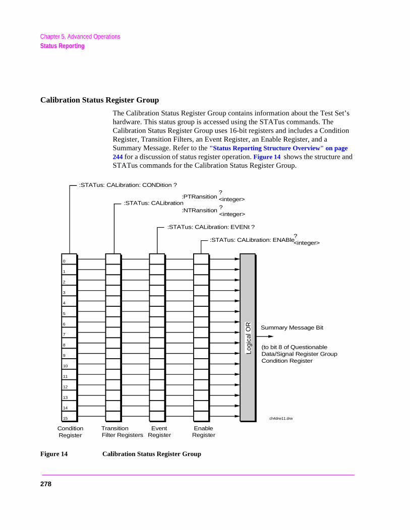
Chapter 5, Advanced OperationsStatus Reporting
et’s
ition
Calibration Status Register Group
The Calibration Status Register Group contains information about the Test Shardware. This status group is accessed using the STATus commands. The Calibration Status Register Group uses 16-bit registers and includes a CondRegister, Transition Filters, an Event Register, an Enable Register, and a Summary Message. Refer to the "Status Reporting Structure Overview" on page 244 for a discussion of status register operation. Figure 14 shows the structure andSTATus commands for the Calibration Status Register Group.
Figure 14 Calibration Status Register Group
0
:STATus: CALibration: ENABle?<integer>
:STATus: CALibration: EVENt ?
:STATus: CALibration:PTRansition
:NTRansition
?<integer>?<integer>
:STATus: CALibration: CONDition ?
Summary Message Bit
ConditionRegister
TransitionFilter Registers
EventRegister
EnableRegister
1
2
3
4
5
6
7
8
9
10
11
12
13
14
Logi
cal O
R
15 ch4drw11.drw
(to bit 8 of QuestionableData/Signal Register GroupCondition Register
278
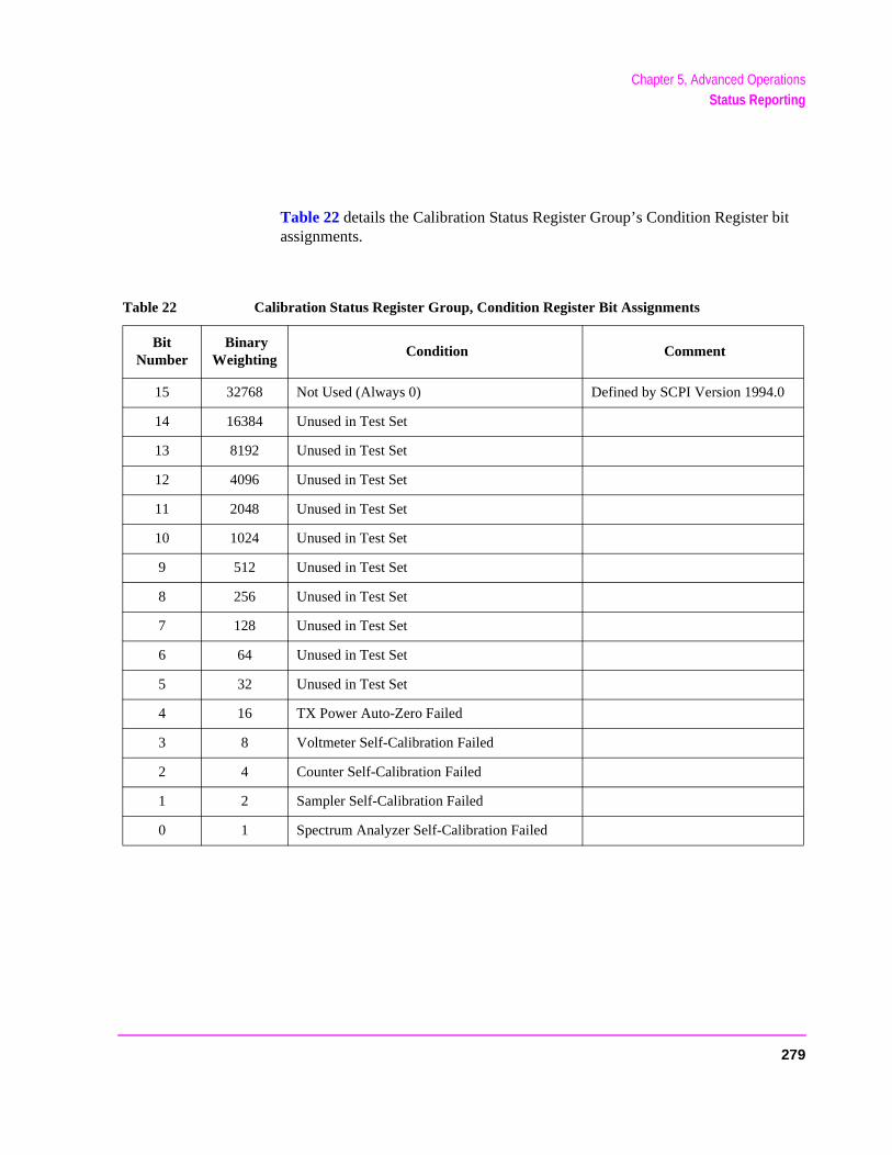
Chapter 5, Advanced OperationsStatus Reporting
it
Table 22 details the Calibration Status Register Group’s Condition Register bassignments.Table 22 Calibration Status Register Group, Condition Register Bit Assignments
Bit Number
Binary Weighting
Condition Comment
15 32768 Not Used (Always 0) Defined by SCPI Version 1994.0
14 16384 Unused in Test Set
13 8192 Unused in Test Set
12 4096 Unused in Test Set
11 2048 Unused in Test Set
10 1024 Unused in Test Set
9 512 Unused in Test Set
8 256 Unused in Test Set
7 128 Unused in Test Set
6 64 Unused in Test Set
5 32 Unused in Test Set
4 16 TX Power Auto-Zero Failed
3 8 Voltmeter Self-Calibration Failed
2 4 Counter Self-Calibration Failed
1 2 Sampler Self-Calibration Failed
0 1 Spectrum Analyzer Self-Calibration Failed
279
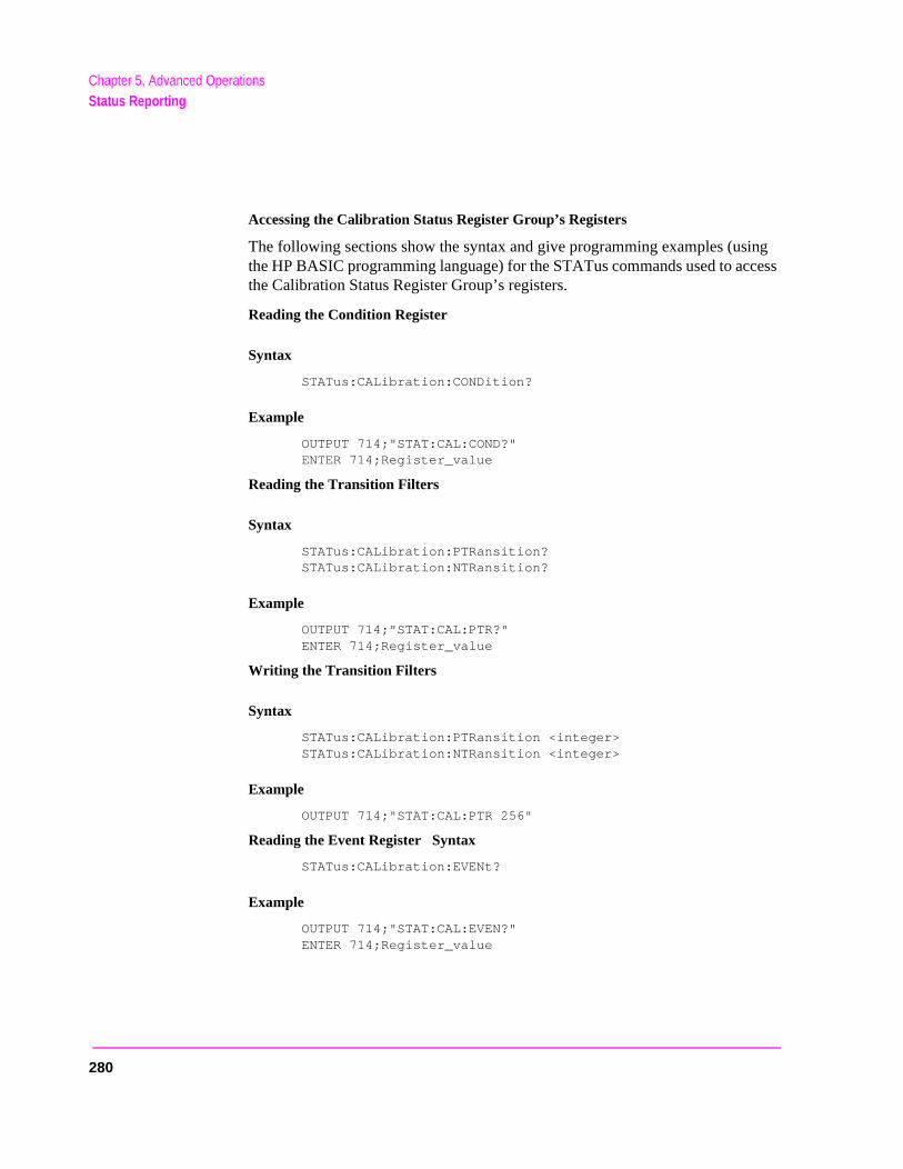
Chapter 5, Advanced OperationsStatus Reporting
Accessing the Calibration Status Register Group’s Registers
The following sections show the syntax and give programming examples (using the HP BASIC programming language) for the STATus commands used to access the Calibration Status Register Group’s registers.
Reading the Condition Register
Syntax
STATus:CALibration:CONDition?
Example
OUTPUT 714;"STAT:CAL:COND?"ENTER 714;Register_value
Reading the Transition Filters
Syntax
STATus:CALibration:PTRansition?STATus:CALibration:NTRansition?
Example
OUTPUT 714;"STAT:CAL:PTR?"ENTER 714;Register_value
Writing the Transition Filters
Syntax
STATus:CALibration:PTRansition <integer>STATus:CALibration:NTRansition <integer>
Example
OUTPUT 714;"STAT:CAL:PTR 256"
Reading the Event Register Syntax
STATus:CALibration:EVENt?
Example
OUTPUT 714;"STAT:CAL:EVEN?"ENTER 714;Register_value
280

Chapter 5, Advanced OperationsStatus Reporting
Clearing the Event Register
The EVENT register is cleared whenever it is queried or whenever the Common Command *CLS is sent to the Test Set.
Reading the Enable Register
Syntax
STATus:CALibration:ENABle?
Example
OUTPUT 714;"STAT:CAL:ENAB?"ENTER 714;Register_value
Writing the Enable Register
Syntax
STATus:CALibration:ENABle <integer>
Example
OUTPUT 714;"STAT:CAL:ENAB 256"
Clearing the Enable Register
The ENABLE register is cleared by writing to it with an integer value of zero.
281
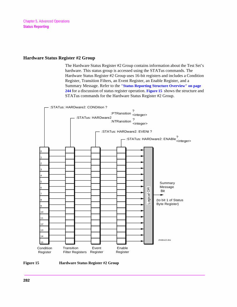
Chapter 5, Advanced OperationsStatus Reporting
Set’s
dition
Hardware Status Register #2 Group
The Hardware Status Register #2 Group contains information about the Test hardware. This status group is accessed using the STATus commands. The Hardware Status Register #2 Group uses 16-bit registers and includes a ConRegister, Transition Filters, an Event Register, an Enable Register, and a Summary Message. Refer to the "Status Reporting Structure Overview" on page 244 for a discussion of status register operation. Figure 15 shows the structure andSTATus commands for the Hardware Status Register #2 Group.
Figure 15 Hardware Status Register #2 Group
0
:STATus: HARDware2: ENABle?<integer>
:STATus: HARDware2: EVENt ?
:STATus: HARDware2:PTRansition
:NTRansition
?<integer>
?<integer>
:STATus: HARDware2: CONDition ?
SummaryMessage Bit
ConditionRegister
TransitionFilter Registers
EventRegister
EnableRegister
1
2
3
4
5
6
7
8
9
10
11
12
13
14
Log
ica
l OR
15ch4drw12.drw
(to bit 1 of StatusByte Register)
282
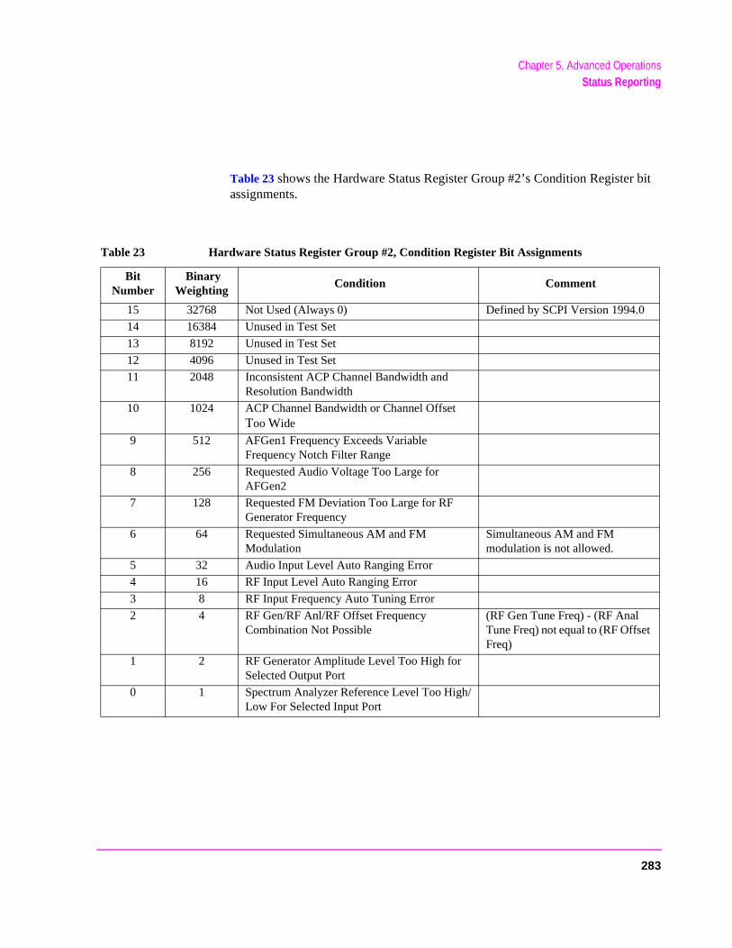
Chapter 5, Advanced OperationsStatus Reporting
bit
Table 23 shows the Hardware Status Register Group #2’s Condition Register assignments.Table 23 Hardware Status Register Group #2, Condition Register Bit Assignments
Bit Number
Binary Weighting
Condition Comment
15 32768 Not Used (Always 0) Defined by SCPI Version 1994.0
14 16384 Unused in Test Set
13 8192 Unused in Test Set
12 4096 Unused in Test Set
11 2048 Inconsistent ACP Channel Bandwidth and Resolution Bandwidth
10 1024 ACP Channel Bandwidth or Channel Offset Too Wide
9 512 AFGen1 Frequency Exceeds Variable Frequency Notch Filter Range
8 256 Requested Audio Voltage Too Large for AFGen2
7 128 Requested FM Deviation Too Large for RF Generator Frequency
6 64 Requested Simultaneous AM and FM Modulation
Simultaneous AM and FM modulation is not allowed.
5 32 Audio Input Level Auto Ranging Error
4 16 RF Input Level Auto Ranging Error
3 8 RF Input Frequency Auto Tuning Error
2 4 RF Gen/RF Anl/RF Offset Frequency Combination Not Possible
(RF Gen Tune Freq) - (RF Anal Tune Freq) not equal to (RF Offset Freq)
1 2 RF Generator Amplitude Level Too High for Selected Output Port
0 1 Spectrum Analyzer Reference Level Too High/Low For Selected Input Port
283

Chapter 5, Advanced OperationsStatus Reporting
Accessing the Hardware Status Register #2 Group’s Registers
The following sections show the syntax and give programming examples (using the HP BASIC programming language) for the STATus commands used to access the Hardware Status Register #2 Group’s registers.
Reading the Condition Register
Syntax
STATus:HARDware2:CONDition?
Example
OUTPUT 714;"STAT:HARD2:COND?"ENTER 714;Register_value
Reading the Transition Filters
Syntax
STATus:HARDware2:PTRansition?STATus:HARDware2:NTRansition?
Example
OUTPUT 714;"STAT:HARD2:PTR?"ENTER 714;Register_value
Writing the Transition Filters
Syntax
STATus:HARDware2:PTRansition <integer>STATus:HARDware2:NTRansition <integer>
Example
OUTPUT 714;"STAT:HARD2:PTR 256"
284

Chapter 5, Advanced OperationsStatus Reporting
Reading the Event Register
Syntax
STATus:HARDware2:EVENt?
Example
OUTPUT 714;"STAT:HARD2:EVEN?"ENTER 714;Register_value
Clearing the Event Register
The EVENT register is cleared whenever it is queried or whenever the Common Command *CLS is sent to the Test Set.
Reading the Enable Register
Syntax
STATus:HARDware2:ENABle?
Example
OUTPUT 714;"STAT:HARD2:ENAB?"ENTER 714;Register_value
Writing the Enable Register
Syntax
STATus:HARDware2:ENABle <integer>
Example
OUTPUT 714;"STAT:HARD2:ENAB 256"
Clearing the Enable Register
The ENABLE register is cleared by writing to it with an integer value of zero.
285
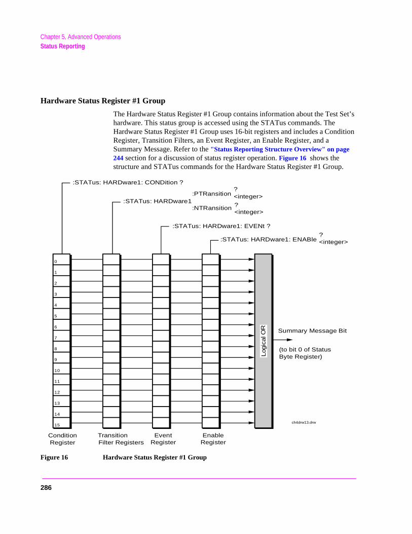
Chapter 5, Advanced OperationsStatus Reporting
Set’s
dition
p.
Hardware Status Register #1 Group
The Hardware Status Register #1 Group contains information about the Test hardware. This status group is accessed using the STATus commands. The Hardware Status Register #1 Group uses 16-bit registers and includes a ConRegister, Transition Filters, an Event Register, an Enable Register, and a Summary Message. Refer to the "Status Reporting Structure Overview" on page 244 section for a discussion of status register operation. Figure 16 shows the structure and STATus commands for the Hardware Status Register #1 Grou
Figure 16 Hardware Status Register #1 Group
0
:STATus: HARDware1: ENABle?<integer>
:STATus: HARDware1: EVENt ?
:STATus: HARDware1:PTRansition
:NTRansition
?<integer>
?<integer>
:STATus: HARDware1: CONDition ?
Summary Message Bit
ConditionRegister
TransitionFilter Registers
EventRegister
EnableRegister
1
2
3
4
5
6
7
8
9
10
11
12
13
14
Log
ical
OR
15ch4drw13.drw
(to bit 0 of StatusByte Register)
286
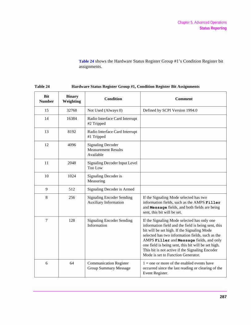
Chapter 5, Advanced OperationsStatus Reporting
bit
Table 24 shows the Hardware Status Register Group #1’s Condition Register assignments.Table 24 Hardware Status Register Group #1, Condition Register Bit Assignments
Bit Number
Binary Weighting
Condition Comment
15 32768 Not Used (Always 0) Defined by SCPI Version 1994.0
14 16384 Radio Interface Card Interrupt #2 Tripped
13 8192 Radio Interface Card Interrupt #1 Tripped
12 4096 Signaling Decoder Measurement Results Available
11 2048 Signaling Decoder Input Level Too Low
10 1024 Signaling Decoder is Measuring
9 512 Signaling Decoder is Armed
8 256 Signaling Encoder Sending Auxiliary Information
If the Signaling Mode selected has two information fields, such as the AMPS Filler and Message fields, and both fields are being sent, this bit will be set.
7 128 Signaling Encoder Sending Information
If the Signaling Mode selected has only one information field and the field is being sent, this bit will be set high. If the Signaling Mode selected has two information fields, such as the AMPS Filler and Message fields, and only one field is being sent, this bit will be set high. This bit is not active if the Signaling Encoder Mode is set to Function Generator.
6 64 Communication Register Group Summary Message
1 = one or more of the enabled events have occurred since the last reading or clearing of the Event Register.
287
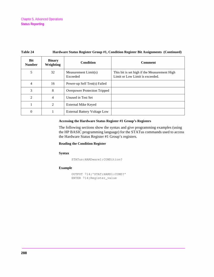
Chapter 5, Advanced OperationsStatus Reporting
Accessing the Hardware Status Register #1 Group’s Registers
The following sections show the syntax and give programming examples (using the HP BASIC programming language) for the STATus commands used to access the Hardware Status Register #1 Group’s registers.
Reading the Condition Register
Syntax
STATus:HARDware1:CONDition?
Example
OUTPUT 714;"STAT:HARD1:COND?"ENTER 714;Register_value
5 32 Measurement Limit(s) Exceeded
This bit is set high if the Measurement High Limit or Low Limit is exceeded.
4 16 Power-up Self Test(s) Failed
3 8 Overpower Protection Tripped
2 4 Unused in Test Set
1 2 External Mike Keyed
0 1 External Battery Voltage Low
Table 24 Hardware Status Register Group #1, Condition Register Bit Assignments (Continued)
Bit Number
Binary Weighting
Condition Comment
288
Chapter 5, Advanced OperationsStatus Reporting
Reading the Transition Filters
Syntax
STATus:HARDware1:PTRansition?STATus:HARDware1:NTRansition?
Example
OUTPUT 714;"STAT:HARD1:PTR?"ENTER 714;Register_value
Writing the Transition Filters
Syntax
STATus:HARDware1:PTRansition <integer>STATus:HARDware1:NTRansition <integer>
Example
OUTPUT 714;"STAT:HARD1:PTR 256"
Reading the Event Register
Syntax
STATus:HARDware1:EVENt?
Example
OUTPUT 714;"STAT:HARD1:EVEN?"ENTER 714;Register_value
289

Chapter 5, Advanced OperationsStatus Reporting
Clearing the Event Register
The EVENT register is cleared whenever it is queried or whenever the Common Command *CLS is sent to the Test Set.
Reading the Enable Register
Syntax
STATus:HARDware1:ENABle?
Example
OUTPUT 714;"STAT:HARD1:ENAB?"ENTER 714;Register_value
Writing the Enable Register
Syntax
STATus:HARDware1:ENABle <integer>
Example
OUTPUT 714;"STAT:HARD1:ENAB 256"
Clearing the Enable Register
The ENABLE register is cleared by writing to it with an integer value of zero.
290
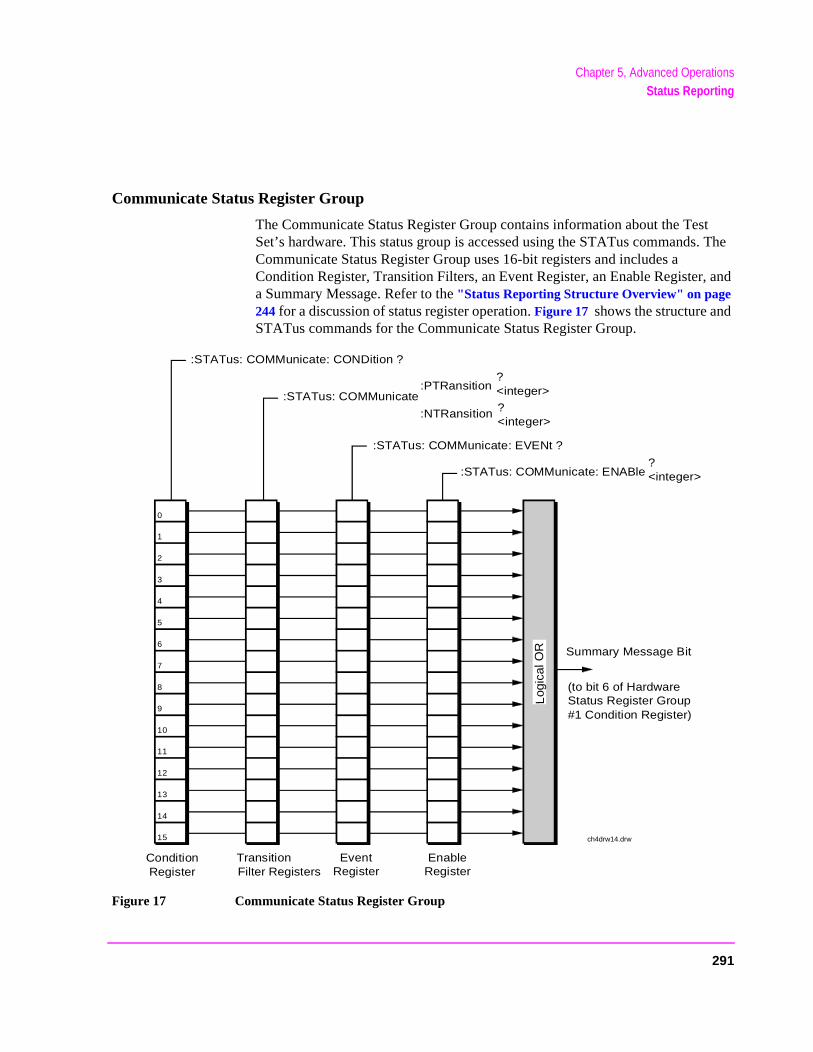
Chapter 5, Advanced OperationsStatus Reporting
. The
, and
Communicate Status Register Group
The Communicate Status Register Group contains information about the Test Set’s hardware. This status group is accessed using the STATus commandsCommunicate Status Register Group uses 16-bit registers and includes a Condition Register, Transition Filters, an Event Register, an Enable Registera Summary Message. Refer to the "Status Reporting Structure Overview" on page 244 for a discussion of status register operation. Figure 17 shows the structure andSTATus commands for the Communicate Status Register Group.
Figure 17 Communicate Status Register Group
0
:STATus: COMMunicate: ENABle?<integer>
:STATus: COMMunicate: EVENt ?
:STATus: COMMunicate:PTRansition
:NTRansition
?<integer>
?<integer>
:STATus: COMMunicate: CONDition ?
Summary Message Bit
ConditionRegister
TransitionFilter Registers
EventRegister
EnableRegister
1
2
3
4
5
6
7
8
9
10
11
12
13
14
Log
ical
OR
15 ch4drw14.drw
(to bit 6 of HardwareStatus Register Group#1 Condition Register)
291
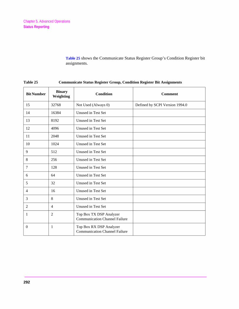
Chapter 5, Advanced OperationsStatus Reporting
r bit
Table 25 shows the Communicate Status Register Group’s Condition Registeassignments.Table 25 Communicate Status Register Group, Condition Register Bit Assignments
Bit Number Binary
Weighting Condition Comment
15 32768 Not Used (Always 0) Defined by SCPI Version 1994.0
14 16384 Unused in Test Set
13 8192 Unused in Test Set
12 4096 Unused in Test Set
11 2048 Unused in Test Set
10 1024 Unused in Test Set
9 512 Unused in Test Set
8 256 Unused in Test Set
7 128 Unused in Test Set
6 64 Unused in Test Set
5 32 Unused in Test Set
4 16 Unused in Test Set
3 8 Unused in Test Set
2 4 Unused in Test Set
1 2 Top Box TX DSP Analyzer Communication Channel Failure
0 1 Top Box RX DSP Analyzer Communication Channel Failure
292
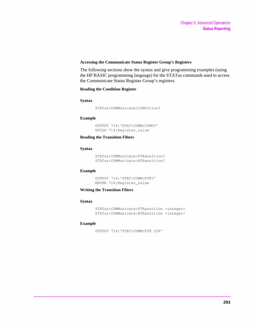
Chapter 5, Advanced OperationsStatus Reporting
Accessing the Communicate Status Register Group’s Registers
The following sections show the syntax and give programming examples (using the HP BASIC programming language) for the STATus commands used to access the Communicate Status Register Group’s registers.
Reading the Condition Register
Syntax
STATus:COMMunicate:CONDition?
Example
OUTPUT 714;"STAT:COMM:COND?"ENTER 714;Register_value
Reading the Transition Filters
Syntax
STATus:COMMunicate:PTRansition?STATus:COMMunicate:NTRansition?
Example
OUTPUT 714;"STAT:COMM:PTR?"ENTER 714;Register_value
Writing the Transition Filters
Syntax
STATus:COMMunicate:PTRansition <integer>STATus:COMMunicate:NTRansition <integer>
Example
OUTPUT 714;"STAT:COMM:PTR 256"
293

Chapter 5, Advanced OperationsStatus Reporting
Reading the Event Register
Syntax
STATus:COMMunicate:EVENt?
Example
OUTPUT 714;"STAT:COMM:EVEN?"ENTER 714;Register_value
Clearing the Event Register
The EVENT register is cleared whenever it is queried or whenever the Common Command *CLS is sent to the Test Set.
Reading the Enable Register
Syntax
STATus:COMMunicate:ENABle?
Example
OUTPUT 714;"STAT:COMM:ENAB?"ENTER 714;Register_value
Writing the Enable Register
Syntax
STATus:COMMunicate:ENABle <integer>
Example
OUTPUT 714;"STAT:COMM:ENAB 256"
Clearing the Enable Register
The ENABLE register is cleared by writing to it with an integer value of zero.
294

Chapter 5, Advanced OperationsHP-IB Service Requests
e e error
SRQ
If rrupt utes
t to
HP-IB Service Requests
The Test Set is capable of generating a “service request” when it requires thActive Controller to take action. Service requests are generally made after thTest Set has completed a task (such as making a measurement) or when ancondition exists (such as an internal self-calibration has failed).
The mechanism by which the Active Controller detects these requests is the interrupt. Interrupts allow for efficient use of system resources, because the Active Controller may be executing a program until an SRQ interrupt occurs.SRQ interrupts are enabled in the Active Controller, the occurrence of an intecan initiate a program branch to a routine which “services” the interrupt (execsome remedial action). The operating and/or programming manuals for eachcontroller describe the controller’s capability to set up and respond to SRQ interrupts.
This section describes the steps necessary to properly configure the Test Serequest service using the Service Request (SRQ) function.
295
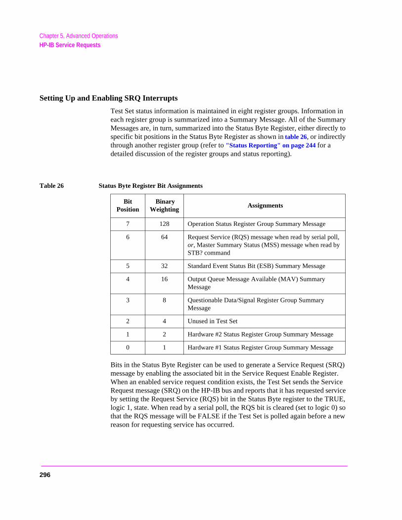
Chapter 5, Advanced OperationsHP-IB Service Requests
Setting Up and Enabling SRQ Interrupts
Test Set status information is maintained in eight register groups. Information in each register group is summarized into a Summary Message. All of the Summary Messages are, in turn, summarized into the Status Byte Register, either directly to specific bit positions in the Status Byte Register as shown in table 26, or indirectly through another register group (refer to "Status Reporting" on page 244 for a detailed discussion of the register groups and status reporting).
Bits in the Status Byte Register can be used to generate a Service Request (SRQ) message by enabling the associated bit in the Service Request Enable Register. When an enabled service request condition exists, the Test Set sends the Service Request message (SRQ) on the HP-IB bus and reports that it has requested service by setting the Request Service (RQS) bit in the Status Byte register to the TRUE, logic 1, state. When read by a serial poll, the RQS bit is cleared (set to logic 0) so that the RQS message will be FALSE if the Test Set is polled again before a new reason for requesting service has occurred.
Table 26 Status Byte Register Bit Assignments
Bit Position
Binary Weighting
Assignments
7 128 Operation Status Register Group Summary Message
6 64 Request Service (RQS) message when read by serial poll, or, Master Summary Status (MSS) message when read by STB? command
5 32 Standard Event Status Bit (ESB) Summary Message
4 16 Output Queue Message Available (MAV) Summary Message
3 8 Questionable Data/Signal Register Group Summary Message
2 4 Unused in Test Set
1 2 Hardware #2 Status Register Group Summary Message
0 1 Hardware #1 Status Register Group Summary Message
296
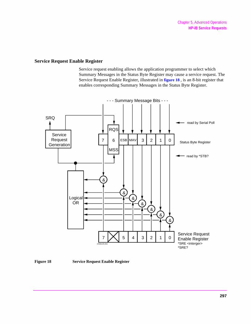
Chapter 5, Advanced OperationsHP-IB Service Requests
Service Request Enable Register
Service request enabling allows the application programmer to select which Summary Messages in the Status Byte Register may cause a service request. The Service Request Enable Register, illustrated in figure 18 , is an 8-bit register that enables corresponding Summary Messages in the Status Byte Register.
Figure 18 Service Request Enable Register
- - - Summary Message Bits - - -
LogicalOR
Service RequestEnable Register*SRE <interger>*SRE?
&&
&
Status Byte Registe
1 07 5 4 3 2
&&
&
read by *STB?
read by Serial PollSRQ
ch4drw15.drw
7 6 ESB MAV 3 2 1 0
RQS
MSS
ServiceRequest
Generation
&
Status Byte Register
297
Chapter 5, Advanced OperationsHP-IB Service Requests
Reading the Service Request Enable Register
The Service Request Enable Register is read with the *SRE? Common Command. The *SRE? query allows the programmer to determine the current contents (bit pattern) of the Service Request Enable Register. The Test Set responds to the *SRE? query by placing the binary-weighted decimal value of the Service Request Enable Register bit pattern into the Output Queue. The decimal value of the bit pattern will be a positive integer in the range 0 to 255. The response data is obtained by reading the Output Queue into a numeric variable, integer or real.
Example BASIC program
10 INTEGER Srv_rqs_enab_rg20 OUTPUT 714;"*SRE?"30 ENTER 714;Srv_rqs_enab_rg40 PRINT Srv_rqs_enab_rg50 END
Example response
18
Writing the Service Request Enable Register
The Service Request Enable Register is written with the *SRE Common Command. The *SRE command sets the bit pattern (bits 0-5 and 7) of the Service Request Enable Register. The Service Request Enable Register allows the programmer to select which condition(s), as defined by bits 0-5 and 7 of the Status Byte Register, will generate a Service Request on the HP-IB bus. The Test Set always ignores bit 6 (binary weight 64) of the bit pattern set by the *SRE command.
The bit pattern set by the *SRE command is determined by selecting the desired condition(s) from the Status Byte Register, setting the value of the bit position(s) to a logical one, setting the value of all non-selected bit positions to a logical zero, and sending the binary-weighted decimal equivalent of bits 0-5 and 7 after the *SRE command. For example, if the programmer wished to have the occurrence of a message available in the Output Queue (bit position 4 in the Status Byte Register) and the occurrence of a condition in the Hardware# 2 Status Register (bit position 1 in the Status Byte Register) to generate a Service Request on the HP-IB bus, the binary-weighted decimal value of the bit pattern for the Service Request Enable Register would be determined as shown in table 27.
298
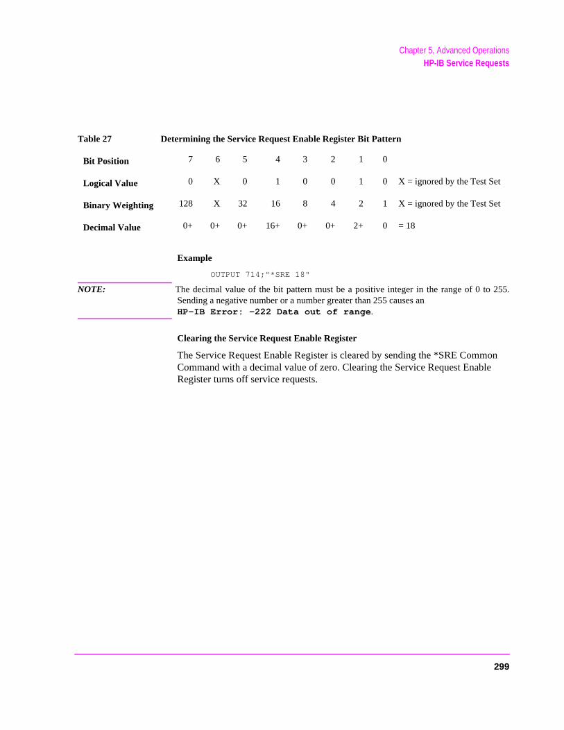
Chapter 5, Advanced OperationsHP-IB Service Requests
Example
OUTPUT 714;"*SRE 18"
NOTE: The decimal value of the bit pattern must be a positive integer in the range of 0 to 255.Sending a negative number or a number greater than 255 causes an HP-IB Error: -222 Data out of range.
Clearing the Service Request Enable Register
The Service Request Enable Register is cleared by sending the *SRE Common Command with a decimal value of zero. Clearing the Service Request Enable Register turns off service requests.
Table 27 Determining the Service Request Enable Register Bit Pattern
Bit Position 7 6 5 4 3 2 1 0
Logical Value 0 X 0 1 0 0 1 0 X = ignored by the Test Set
Binary Weighting 128 X 32 16 8 4 2 1 X = ignored by the Test Set
Decimal Value 0+ 0+ 0+ 16+ 0+ 0+ 2+ 0 = 18
299

Chapter 5, Advanced OperationsHP-IB Service Requests
.
Procedure for Generating a Service Request
The following steps outline a generalized procedure for properly setting up the Test Set to generate a Service Request (SRQ) message to the Active Controller. This procedure does not include instructions for setting up the Active Controller to respond to the Service Request message generated by the Test Set. Refer to the operating and/or programming manuals for each controller for information describing the controller’s capability to set up and respond to SRQ interrupts
For register groups with Condition Registers and Transition Filters start at step 1. For register groups with no Condition Register or Transition Filters start at step 5.
1. Determine which conditions, as defined by their bit positions in the Register Group Condition Register, should cause the Summary Message to be set TRUE if they occur.
2. Determine the polarity of the bit-state transition which will indicate that the condition has occurred.
3. Set the Register Group Transition Filters to the correct polarity to pass the bit-state tran-sition to the Event Register.
4. Go to step 6.
5. Determine which conditions, as defined by their bit positions in the Register Group Event Register, should cause the Summary Message to be set TRUE if they occur.
6. Set the correct bits in the Register Group Enable Register to generate the Summary Message if the condition has been latched into the Register Group Event Register.
7. If the Summary Message is a bit in a Register Group that is not the Status Byte Register go to step 1.
8. Set the correct bits in the Service Request Enable Register for all Register Group Sum-mary Messages selected in steps 1 through 6.
300
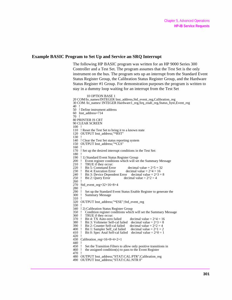
Chapter 5, Advanced OperationsHP-IB Service Requests
Example BASIC Program to Set Up and Service an SRQ Interrupt
The following HP BASIC program was written for an HP 9000 Series 300 Controller and a Test Set. The program assumes that the Test Set is the only instrument on the bus. The program sets up an interrupt from the Standard Event Status Register Group, the Calibration Status Register Group, and the Hardware Status Register #1 Group. For demonstration purposes the program is written to stay in a dummy loop waiting for an interrupt from the Test Set
10 OPTION BASE 120 COM/Io_names/INTEGER Inst_address,Std_event_reg,Calibration_reg30 COM /Io_names/ INTEGER Hardware1_reg,Srq_enab_reg,Status_byte,Event_reg40 !50 ! Define instrument address60 Inst_address=71470 !80 PRINTER IS CRT90 CLEAR SCREEN100 !110 ! Reset the Test Set to bring it to a known state120 OUTPUT Inst_address;"*RST"130 !140 ! Clear the Test Set status reporting system150 OUTPUT Inst_address;"*CLS"160 !170 ! Set up the desired interrupt conditions in the Test Set:180 !190 ! 1) Standard Event Status Register Group200 ! Event register conditions which will set the Summary Message210 ! TRUE if they occur:220 ! Bit 5: Command Error decimal value = 2^5 = 32230 ! Bit 4: Execution Error decimal value = 2^4 = 16240 ! Bit 3: Device Dependent Error decimal value = 2^3 = 8250 ! Bit 2: Query Error decimal value = 2^2 = 4260 !270 Std_event_reg=32+16+8+4280 !290 ! Set up the Standard Event Status Enable Register to generate the300 ! Summary Message310 !320 OUTPUT Inst_address;"*ESE";Std_event_reg330 !340 ! 2) Calibration Status Register Group350 ! Condition register conditions which will set the Summary Message360 ! TRUE if they occur:370 ! Bit 4: TX Auto-zero failed decimal value = 2^4 = 16380 ! Bit 3: Voltmeter Self-cal failed decimal value = 2^3 = 8390 ! Bit 2: Counter Self-cal failed decimal value = 2^2 = 4400 ! Bit 1: Sampler Self_cal failed decimal value = 2^1 = 2410 ! Bit 0: Spec Anal Self-cal failed decimal value = 2^0 = 1420 !430 Calibration_reg=16+8+4+2+1440 !450 ! Set the Transition Filters to allow only positive transitions in460 ! the assigned condition(s) to pass to the Event Register470 !480 OUTPUT Inst_address;"STAT:CAL:PTR";Calibration_reg490 OUTPUT Inst_address;"STAT:CAL:NTR 0"
301
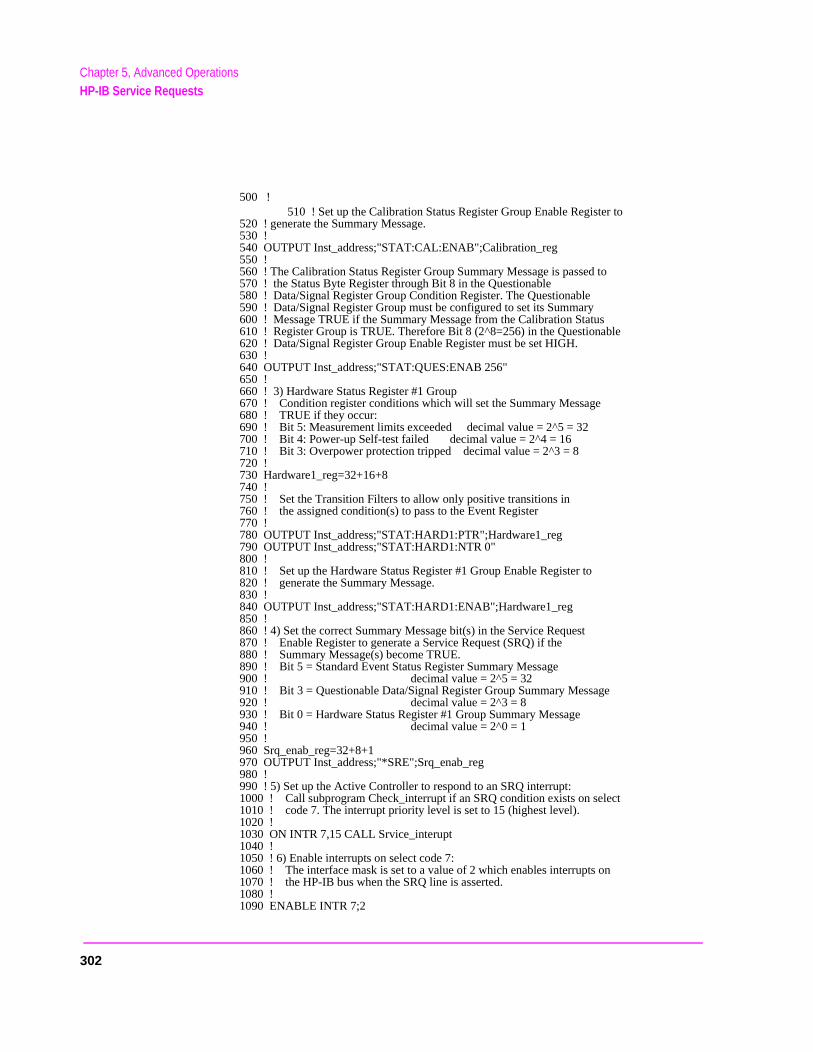
3
Chapter 5, Advanced OperationsHP-IB Service Requests
500 !510 ! Set up the Calibration Status Register Group Enable Register to
520 ! generate the Summary Message.530 !540 OUTPUT Inst_address;"STAT:CAL:ENAB";Calibration_reg550 !560 ! The Calibration Status Register Group Summary Message is passed to570 ! the Status Byte Register through Bit 8 in the Questionable580 ! Data/Signal Register Group Condition Register. The Questionable590 ! Data/Signal Register Group must be configured to set its Summary600 ! Message TRUE if the Summary Message from the Calibration Status610 ! Register Group is TRUE. Therefore Bit 8 (2^8=256) in the Questionable620 ! Data/Signal Register Group Enable Register must be set HIGH.630 !640 OUTPUT Inst_address;"STAT:QUES:ENAB 256"650 !660 ! 3) Hardware Status Register #1 Group670 ! Condition register conditions which will set the Summary Message680 ! TRUE if they occur:690 ! Bit 5: Measurement limits exceeded decimal value = 2^5 = 32700 ! Bit 4: Power-up Self-test failed decimal value = 2^4 = 16710 ! Bit 3: Overpower protection tripped decimal value = 2^3 = 8720 !730 Hardware1_reg=32+16+8740 !750 ! Set the Transition Filters to allow only positive transitions in760 ! the assigned condition(s) to pass to the Event Register770 !780 OUTPUT Inst_address;"STAT:HARD1:PTR";Hardware1_reg790 OUTPUT Inst_address;"STAT:HARD1:NTR 0"800 !810 ! Set up the Hardware Status Register #1 Group Enable Register to820 ! generate the Summary Message.830 !840 OUTPUT Inst_address;"STAT:HARD1:ENAB";Hardware1_reg850 !860 ! 4) Set the correct Summary Message bit(s) in the Service Request870 ! Enable Register to generate a Service Request (SRQ) if the880 ! Summary Message(s) become TRUE.890 ! Bit 5 = Standard Event Status Register Summary Message900 ! decimal value = 2^5 = 32910 ! Bit 3 = Questionable Data/Signal Register Group Summary Message920 ! decimal value = 2^3 = 8930 ! Bit 0 = Hardware Status Register #1 Group Summary Message940 ! decimal value = 2^0 = 1950 !960 Srq_enab_reg=32+8+1970 OUTPUT Inst_address;"*SRE";Srq_enab_reg980 !990 ! 5) Set up the Active Controller to respond to an SRQ interrupt:1000 ! Call subprogram Check_interrupt if an SRQ condition exists on select1010 ! code 7. The interrupt priority level is set to 15 (highest level).1020 !1030 ON INTR 7,15 CALL Srvice_interupt1040 !1050 ! 6) Enable interrupts on select code 7:1060 ! The interface mask is set to a value of 2 which enables interrupts on1070 ! the HP-IB bus when the SRQ line is asserted.1080 !1090 ENABLE INTR 7;2
02
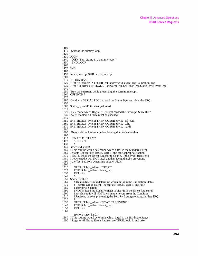
Chapter 5, Advanced OperationsHP-IB Service Requests
1100 !1110 ! Start of the dummy loop:1120 !1130 LOOP1140 DISP "I am sitting in a dummy loop."1150 END LOOP1160 !1170 END1180 !1190 Srvice_interupt:SUB Srvice_interupt1200 !1210 OPTION BASE 11220 COM /Io_names/ INTEGER Inst_address,Std_event_reg,Calibration_reg1230 COM / Io_names/ INTEGER Hardware1_reg,Srq_enab_reg,Status_byte,Event_reg1240 !1250 !Turn off interrupts while processing the current interrupt.1260 OFF INTR 71270 !1280 !Conduct a SERIAL POLL to read the Status Byte and clear the SRQ:1290 !1300 Status_byte=SPOLL(Inst_address)1310 !1320 ! Determine which Register Group(s) caused the interrupt. Since three1330 ! were enabled, all three must be checked:1340 !1350 IF BIT(Status_byte,5) THEN GOSUB Srvice_std_evnt1360 IF BIT(Status_byte,3) THEN GOSUB Srvice_calib1370 IF BIT(Status_byte,0) THEN GOSUB Srvice_hard11380 !1390 ! Re-enable the interrupt before leaving the service routine1400 !1410 ENABLE INTR 7;21420 SUBEXIT1430 !1440 Srvice_std_evnt:!1450 ! This routine would determine which bit(s) in the Standard Event1460 ! Status Register are TRUE, logic 1, and take appropriate action.1470 ! NOTE: Read the Event Register to clear it. If the Event Register is1480 ! not cleared it will NOT latch another event, thereby preventing1490 ! the Test Set from generating another SRQ.1500 !1510 OUTPUT Inst_address;"*ESR?"1520 ENTER Inst_address;Event_reg1530 RETURN1540 !1550 Service_calib:!1560 ! This routine would determine which bit(s) in the Calibration Status1570 ! Register Group Event Register are TRUE, logic 1, and take1580 ! appropriate action.1590 ! NOTE: Read the Event Register to clear it. If the Event Register is1600 ! not cleared it will NOT latch another event from the Condition1610 ! Register, thereby preventing the Test Set from generating another SRQ.1620 !1630 OUTPUT Inst_address;"STAT:CAL:EVEN?"1640 ENTER Inst_address;Event_reg1650 RETURN1660
!1670 Srvice_hard1:!1680 ! This routine would determine which bit(s) in the Hardware Status1690 ! Register #1 Group Event Register are TRUE, logic 1, and take
303
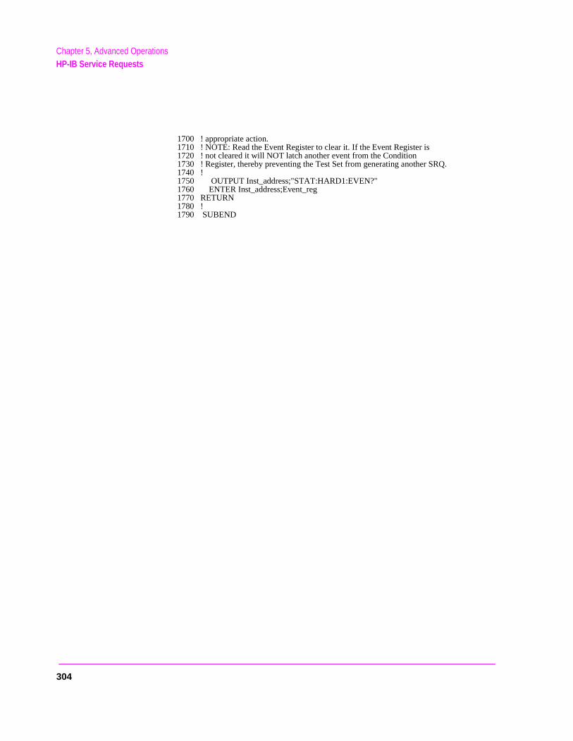
304
Chapter 5, Advanced OperationsHP-IB Service Requests
1700 ! appropriate action.1710 ! NOTE: Read the Event Register to clear it. If the Event Register is1720 ! not cleared it will NOT latch another event from the Condition1730 ! Register, thereby preventing the Test Set from generating another SRQ.1740 !1750 OUTPUT Inst_address;"STAT:HARD1:EVEN?"1760 ENTER Inst_address;Event_reg1770 RETURN1780 !1790 SUBEND
Chapter 5, Advanced OperationsInstrument Initialization
Instrument Initialization
This section discusses the various methods available to the programmer to initialize the Test Set to a known state.
With over 22 instruments utilizing greater than 25 screens containing hundreds of fields which can be programmed through the HP-IB bus, a hard copy list of the default condition for every field in every instrument screen would be cumbersome. The recommended method of determining the default condition for every field in a particular instrument screen is to select the PRESET key, display the instrument screen of interest and view the contents of the fields.
Apart from the individual instruments it is important, from a programmatic perspective, to know the default conditions of the I/O configuration of the Test Set and how it may be affected by the various methods of initialization. Seven screens are used to control the I/O configuration of the Test Set:
CONFIGURE screen I/O CONFIGURE screen PRINT CONFIGURE screen TESTS (Main Menu) screen TESTS (Execution Conditions) screen TESTS ( External Devices) screen TESTS (Printer Setup) screen
The following sections discuss how the various methods of initialization affect these seven screens as well as the Status Reporting Structure of the Test Set.
305

Chapter 5, Advanced OperationsInstrument Initialization
e),
ds
the
are be. s) the
Methods of Initialization
There are six methods of initializing the Test Set:
Power On Reset Front panel PRESET key *RST IEEE 488.2 Common Command Device Clear (DCL) HP-IB Bus Command Selected Device Clear (SDC) HP-IB Bus Command Interface Clear (IFC) HP-IB Bus Command
When the Test Set is initialized some fields are “restored” (put back to their default state), some fields are “maintained” (kept at their current state or valuand some fields are “initialized” (returned to their default value).
The following sections discuss the effects each of the six initialization methohas on the Test Set.
Power-On Reset
The Power-On Reset is accomplished by applying or cycling AC/DC power toTest Set.
For the CONFIGURE, PRINT CONFIGURE, TESTS (Execution Conditions),TESTS (Printer Setup) and I/O CONFIGURE screens, table 28 lists the fields which are restored/initialized when the Test Set AC/DC power is cycled. Therestored state or initialized value is listed below the field name. Fields which not listed are maintained at their current value, whatever that may happen toAll fields in the TESTS (Main Menu) screen and the TESTS (External Devicescreen are maintained at their current state/value. The current state/value ofmaintained fields can be ascertained programmatically.
306
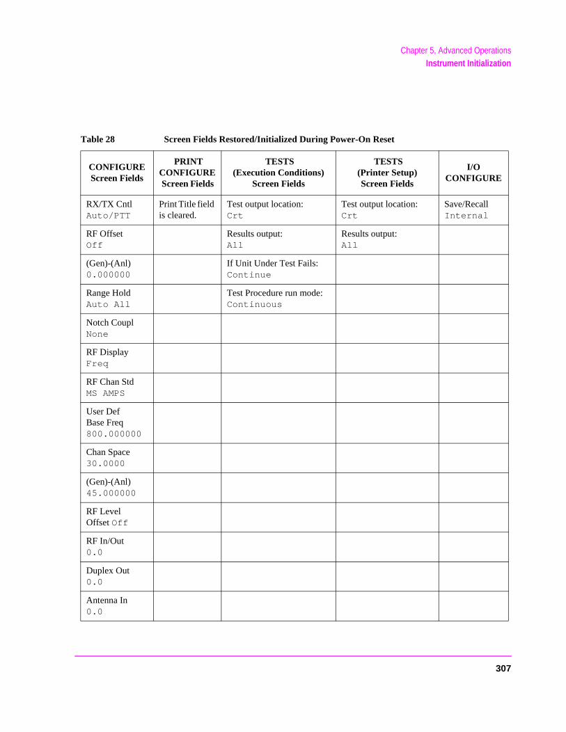
Chapter 5, Advanced OperationsInstrument Initialization
Table 28 Screen Fields Restored/Initialized During Power-On Reset
CONFIGURE Screen Fields
PRINT CONFIGURE Screen Fields
TESTS (Execution Conditions)
Screen Fields
TESTS (Printer Setup) Screen Fields
I/O CONFIGURE
RX/TX Cntl Auto/PTT
Print Title field is cleared.
Test output location:Crt
Test output location: Crt
Save/Recall Internal
RF Offset Off
Results output:All
Results output:All
(Gen)-(Anl) 0.000000
If Unit Under Test Fails: Continue
Range Hold Auto All
Test Procedure run mode: Continuous
Notch Coupl None
RF Display Freq
RF Chan Std MS AMPS
User Def Base Freq 800.000000
Chan Space 30.0000
(Gen)-(Anl) 45.000000
RF Level Offset Off
RF In/Out0.0
Duplex Out0.0
Antenna In0.0
307

Chapter 5, Advanced OperationsInstrument Initialization
, able
able
able
.
The Power-On Reset condition in the Test Set was specifically designed to configure the instruments for manual testing of an FM radio. The Power-On Reset default display screen is the RX TEST screen. Other operational characteristics are also affected by the Power-On Reset as follows:
• The Power-up self-test diagnostics are performed. • The Contents of the SAVE/RECALL registers are not affected. • All pending operations are aborted. • Measurement triggering is set to TRIG:MODE:SETT FULL;RETR REP • All Enable registers are cleared: Service Request, Standard Event, Communicate
Hardware #1, Hardware #2, Operation, Calibration, Call Processing and QuestionData/Signal.
• All Negative Transition Filter registers are initialized to all zeros: Communicate, Hardware #1, Hardware #2, Operation, Calibration, Call Processing and QuestionData/Signal.
• All Positive Transition Filter registers are initialized to all ones: Communicate, Hardware #1, Hardware #2, Operation, Calibration, Call Processing and QuestionData/Signal.
• Any previously received Operation Complete command (*OPC) is cleared. • Any previously received Operation Complete query command (*OPC?) is cleared• Calibration data is not affected. • The HP-IB interface is reset (any pending Service Request is cleared.) • The contents of the RAM memory are unaffected. • The Test Set’s display screen is in the UNLOCKED state.
308

Chapter 5, Advanced OperationsInstrument Initialization
Front-panel PRESET Key
The Front-panel Reset is accomplished by pressing the PRESET key on the front panel of the Test Set.
For the CONFIGURE, PRINT CONFIGURE, TESTS (Execution Conditions), TESTS (Printer Setup) and I/O CONFIGURE screens, table 29 lists the fields which are restored/initialized when the front-panel PRESET key is pressed. The restored state or initialized value is listed below the field name. Fields which are not listed are maintained at their current value, whatever that may happen to be. All fields in the TESTS (Main Menu) screen and the TESTS (External Devices) screen are maintained at their current state/value. The current state/value of the maintained fields can be ascertained programmatically.
309
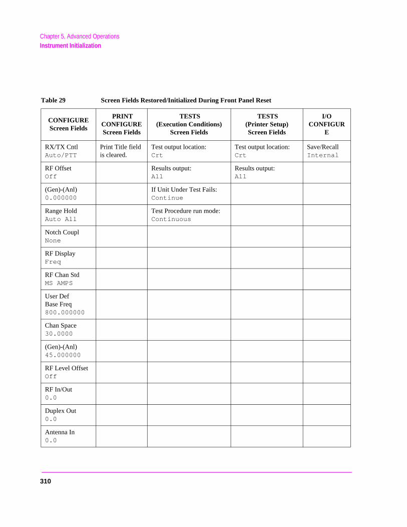
Chapter 5, Advanced OperationsInstrument Initialization
Table 29 Screen Fields Restored/Initialized During Front Panel Reset
CONFIGURE Screen Fields
PRINT CONFIGURE Screen Fields
TESTS (Execution Conditions)
Screen Fields
TESTS (Printer Setup)Screen Fields
I/O CONFIGUR
E
RX/TX Cntl Auto/PTT
Print Title field is cleared.
Test output location:Crt
Test output location: Crt
Save/Recall Internal
RF Offset Off
Results output:All
Results output: All
(Gen)-(Anl) 0.000000
If Unit Under Test Fails: Continue
Range Hold Auto All
Test Procedure run mode:Continuous
Notch Coupl None
RF Display Freq
RF Chan Std MS AMPS
User Def Base Freq 800.000000
Chan Space 30.0000
(Gen)-(Anl) 45.000000
RF Level Offset Off
RF In/Out0.0
Duplex Out 0.0
Antenna In 0.0
310

Chapter 5, Advanced OperationsInstrument Initialization
.
cate, nable
1, nal.,
nal.
The Front-panel Reset condition in the Test Set was specifically designed to configure the instruments for manual testing of an FM radio. The Front-panel Reset default display screen is the RX TEST screen. Other operational characteristics are also affected by the Front-panel Reset as follows:
• All pending operations are aborted. • Measurement triggering is set to TRIG:MODE:SETT FULL;RETR REP. • Any previously received Operation Complete command (*OPC) is cleared. • Any previously received Operation Complete query command (*OPC?) is cleared• The Test Set’s display screen is in the UNLOCKED state. • The Power-up self-test diagnostics are not performed. • The HP-IB interface is not reset (any pending Service Request is not cleared.) • The Contents of the SAVE/RECALL registers are not affected. • Calibration data is not affected. • All Enable registers are unaffected: Service Request, Standard Event, Communi
Hardware #1, Hardware #2, Operation, Calibration, Call Processing and QuestioData/Signal.
• All Negative Transition Filter registers are unaffected: Communicate, Hardware #Hardware #2, Operation, Calibration,Call Processing and Questionable Data/Sig
• All Positive Transition Filter registers are unaffected: Communicate, Hardware #1Hardware #2, Operation, Calibration,Call Processing and Questionable Data/Sig
• The contents of the RAM memory are unaffected.
311

Chapter 5, Advanced OperationsInstrument Initialization
*RST IEEE 488.2 Common Command
The *RST Reset is accomplished by sending the *RST Common Command to the Test Set through the HP-IB bus.
For the CONFIGURE, PRINT CONFIGURE, TESTS (Execution Conditions), TESTS (Printer Setup) and I/O CONFIGURE screens, table 30 lists the fields which are restored/initialized when the *RST command is received. The restored state or initialized value is listed below the field name. Fields which are not listed are maintained at their current value, whatever that may happen to be. All fields in the TESTS (Main Menu) screen and the TESTS (External Devices) screen are maintained at their current state/value. The current state/value of the maintained fields can be ascertained programmatically.
312
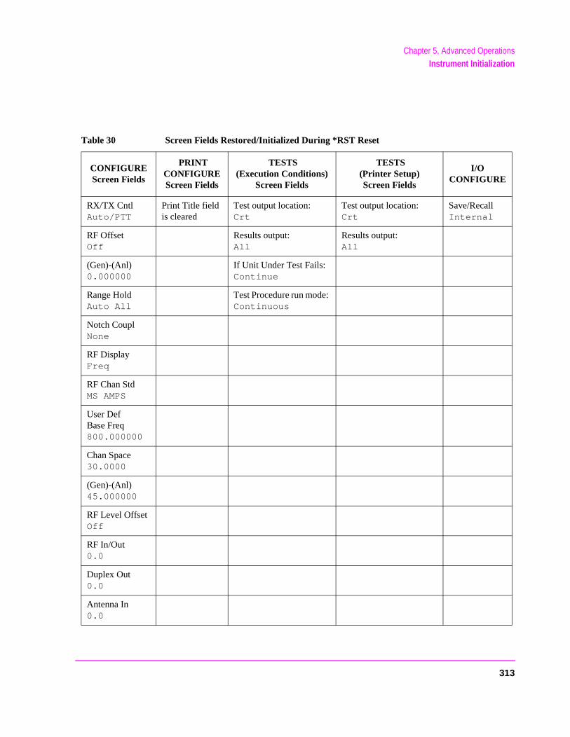
Chapter 5, Advanced OperationsInstrument Initialization
Table 30 Screen Fields Restored/Initialized During *RST Reset
CONFIGURE Screen Fields
PRINT CONFIGURE Screen Fields
TESTS(Execution Conditions)
Screen Fields
TESTS(Printer Setup) Screen Fields
I/O CONFIGURE
RX/TX Cntl Auto/PTT
Print Title field is cleared
Test output location: Crt
Test output location: Crt
Save/Recall Internal
RF Offset Off
Results output: All
Results output: All
(Gen)-(Anl) 0.000000
If Unit Under Test Fails: Continue
Range Hold Auto All
Test Procedure run mode: Continuous
Notch Coupl None
RF Display Freq
RF Chan Std MS AMPS
User Def Base Freq 800.000000
Chan Space 30.0000
(Gen)-(Anl) 45.000000
RF Level Offset Off
RF In/Out 0.0
Duplex Out 0.0
Antenna In 0.0
313

Chapter 5, Advanced OperationsInstrument Initialization
.
cate, able
1, nal. ,
nal.
The *RST Reset condition in the Test Set was specifically designed to configure the instruments for manual testing of an FM radio. The *RST Reset default display screen is the RX TEST screen. Other operational characteristics are also affected by the *RST reset as follows:
• All pending operations are aborted. • Measurement triggering is set to TRIG:MODE:SETT FULL;RETR REP. • Any previously received Operation Complete command (*OPC) is cleared. • Any previously received Operation Complete query command (*OPC?) is cleared• The Test Set’s display screen is in the UNLOCKED state. • The Power-up self-test diagnostics are not performed.• The Contents of the SAVE/RECALL registers are not affected. • Calibration data is not affected. • The HP-IB interface is not reset (any pending Service Request is not cleared). • All Enable registers are unaffected: Service Request, Standard Event, Communi
Hardware #1, Hardware #2, Operation, Calibration,Call Processing and QuestionData/Signal.
• All Negative Transition Filter registers are unaffected: Communicate, Hardware #Hardware #2, Operation, Calibration,Call Processing and Questionable Data/Sig
• All Positive Transition Filter registers are unaffected: Communicate, Hardware #1Hardware #2, Operation, Calibration,Call Processing and Questionable Data/Sig
• The contents of the RAM memory are unaffected. • The contents of the Output Queue are unaffected. • The contents of the Error Queue are unaffected.
314

Chapter 5, Advanced OperationsInstrument Initialization
#1, nal.
, Op-
Op-
Device Clear (DCL) HP-IB Bus Command
The Device Clear (DCL) Reset is accomplished by sending the DCL message to the Test Set through the HP-IB bus.
The DCL command clears the Input Buffer and Output Queue, clears any commands in process, puts the Test Set into the Operation Complete idle state, and prepares the Test Set to receive new commands. The DCL bus command does not change any settings or stored data (except as noted previously), interrupt front panel I/O, interrupt any Test Set operation in progress (except as noted previously), or change the contents of the Status Byte Register (other than clearing the MAV bit as a consequence of clearing the Output Queue).
The DCL bus command has no effect on the I/O CONFIGURE, CONFIGURE, PRINT CONFIGURE, or TESTS (Main Menu, Execution Conditions, External Devices, Printer Setup) screens.
Other operational characteristics are also affected by the DCL bus command as follows:
• The Power-up self-test diagnostics are not performed.
• The HP-IB interface is not reset (any pending Service Request is not cleared)
• Measurement triggering is not affected.
• Calibration data is not affected.
• The Contents of the SAVE/RECALL registers are not affected.
• All Enable registers are unaffected: Service Request, Standard Event, HardwareHardware #2, Operation, Calibration,Call Processing and Questionable Data/Sig
• All Negative Transition Filter registers are unaffected: Hardware #1, Hardware #2eration, Calibration,Call Processing and Questionable Data/Signal.
• All Positive Transition Filter registers are unaffected: Hardware #1, Hardware #2,eration, Calibration,Call Processing and Questionable Data/Signal.
• The contents of the RAM memory are unaffected.
• The contents of the Error Queue are unaffected.
• The state of the Test Set’s display screen is unaffected.
315

Chapter 5, Advanced OperationsInstrument Initialization
Selected Device Clear (SDC) HP-IB Bus Command
The Selected Device Clear (SDC) Reset is accomplished by sending the SDC message to the Test Set through HP-IB. The Test Set responds to the Selected Device Clear (SDC) and the Device Clear (DCL) bus commands equally. Refer to the "Device Clear (DCL) HP-IB Bus Command" on page 315 for a description of the effects of the SDC Reset.
316

Chapter 5, Advanced OperationsInstrument Initialization
#1, nal.
, Op-
Op-
Interface Clear (IFC) HP-IB Bus Command
The Interface Clear (IFC) Reset is accomplished by having the Active Controller send the ABORT message to the HP-IB bus (ABORT message = IFC bus control line TRUE for 100 ms).
The IFC bus command unconditionally terminates all HP-IB bus activity and the Test Set is unaddressed.
The IFC bus command has no effect on the I/O CONFIGURE, CONFIGURE, PRINT CONFIGURE, or TESTS (Main Menu, Execution Conditions, External Devices, Printer Setup) screens.
Other operational characteristics are also affected by the IFC bus command as follows:
• The Power-up self-test diagnostics are not performed.
• The HP-IB interface is not reset (any pending Service Request is not cleared).
• The Contents of the SAVE/RECALL registers are not affected.
• Measurement triggering is not affected.
• Calibration data is not affected .
• All Enable registers are unaffected: Service Request, Standard Event, HardwareHardware #2, Operation, Calibration,Call Processing and Questionable Data/Sig
• All Negative Transition Filter registers are unaffected: Hardware #1, Hardware #2eration, Calibration,Call Processing and Questionable Data/Signa.l
• All Positive Transition Filter registers are unaffected: Hardware #1, Hardware #2,eration, Calibration,Call Processing and Questionable Data/Signal.
• The contents of the RAM memory are unaffected.
• The contents of the Error Queue are unaffected.
• The contents of the Output Queue are unaffected.
• The state of the Test Set display screen is not affected
317
Chapter 5, Advanced OperationsPassing Control
Passing Control
Communications on the HP-IB bus are accomplished according to a precisely defined set of rules (IEEE 488.1 and 488.2 Standards). Communication (data transfer) is accomplished by designating one device to be a talker (source of data or commands) and designating one or more devices to be listeners (receivers of data or commands). The device on the bus responsible for designating talkers and listeners is the Controller.
The structure of the HP-IB bus allows for more than one Controller to be connected to the bus at the same time. As a means of ensuring that orderly communications can be established on power-up or when communications have failed, the rules state that only one Controller can unconditionally demand control of the bus (through the IFC line). This controller is referred to as the System Controller. There can be only one System Controller connected to the bus at any time.
As a means of ensuring orderly communications in environments where more than one controller is connected to the bus, the rules state that only one Controller can be actively addressing talkers and listeners at any given time. This device is referred to as the Active Controller. The System Controller is the default Active Controller on power-up or after a bus reset. Controllers which are not the Active Controller are referred to as Non-Active Controllers. The Active Controller can pass control of device addressing to one of the Non-Active Controllers. Additionally, Non-Active Controllers can request control from the Active Controller.
The process by which the Active Controller passes device addressing responsibility to a Non-Active Controller is referred to as Passing Control. The Active Controller must first address the prospective new Active Controller to Talk, after which it sends the Take Control Talker (TCT) message across the bus. If the other Controller accepts the message it assumes the role of Active Controller and the previous Active Controller becomes a Non-Active Controller.
The Test Set has bus control capability (Active/Non-Active Controller). Additionally the Test Set can be also be configured as the System Controller. By definition then, the Test Set has the capability to demand control, pass control, accept control, and request control of the bus depending upon its configuration, its current operating mode, and the system configuration. Many possibilities for passing control among several controllers on the same bus exist. Attempting to identify all the possible techniques of passing control in such a system is beyond the scope of this document (refer to the IEEE 488.1 and 488.2 Standards for additional information).
318
Chapter 5, Advanced OperationsPassing Control
Configuring the Test Set as the System Controller
To configure the Test Set as a System Controller, select the I/O CONFIGURE screen, position the cursor to the Mode field using the Cursor Control knob, highlight the Mode field by pushing the Rotary Knob, select Control from the Choices menu. As a consequence of setting the Test Set to be the System Controller it will also become the Active Controller. The letter C appears in the upper-right corner of the display to indicate that the Test Set is now the Active Controller.
If the Test Set is the only controller on the bus it must be configured as the System Controller. If the Test Set is not the only controller on the bus, then whether or not it is configured as the System Controller would depend upon three issues:
1. whether or not other controllers have System Controller capability2. which controller will be the Active Controller upon power-up3. which Controller will be monitoring the bus to determine if communications have
failed (only the System Controller can unconditionally demand control of the bus and reset it to a known state using the IFC line)
Ensure that only one Controller connected to the bus is configured as the System Controller or bus conflicts will occur.
When Active Controller Capability is Required
The Test Set must be the Active Controller on the bus under the following conditions:
1. whenever the Test Set needs to control any device connected to the HP-IB bus, such as an external disk drive, an external printer, or an external instrument
2. whenever a screen image is printed to an external HP-IB printer
3. Whenever an instrument configuration is saved or recalled from an external HP-IB disk drive
4. Whenever running any HP 11807 Radio Test Software package which uses an external HP-IB device such as a disk drive, a printer, or an instrument
5. Whenever running any IBASIC program which uses an external HP-IB device such as a disk drive, a printer, or an instrument
319

Chapter 5, Advanced OperationsPassing Control
Passing Control to the Test Set
Control is passed to the Test Set when it is addressed to TALK and then receives the Take Control Talker (TCT) command. The programming or controller command which implements the pass control protocol as outlined in the IEEE 488.1 and 488.2 Standards is language/controller specific. Refer to the appropriate language/controller documentation for specific implementations.
Before passing control to the Test Set the Active Controller should send the Test Set the address to use when passing control back. This is accomplished using the *PCB Common Command. The *PCB command tells the Test Set which address should be used when passing control back to another bus controller. Before passing bus control to the Test Set, the currently active controller can use the *PCB command to tell the Test Set where to send the Take Control (TCT) command when the Test Set is ready to give up active control of the bus. The command is followed by a number which contains the bus address of the device that should become the next active controller. The number must round to an integer in the range 0 to 30 decimal. The command may be followed by two numbers. The first will be used as the primary address, the second as the secondary address of the next active controller.
320
Chapter 5, Advanced OperationsPassing Control
(IFC).
ller aving/
(IFC).
ng a rom
Passing Control Back to Another Controller
The Test Set has two methods of passing control back to another controller: 1) automatically and 2) using the IBASIC PASS CONTROL command from an IBASIC program. The two methods are described in the following sections.
Passing Control Back Automatically
The Test Set will automatically pass control back to the controller whose address was specified in the *PCB Common Command or to a default address of 0 (decimal) if no *PCB command was received. Control will automatically be passed under the following conditions:
Test Set is the Active Controller and an IBASIC Program is Running
• The IBASIC program running in the Test Set is PAUSED.
• The IBASIC program running in the Test Set finishes executing.
• An IBASIC RESET occurs while the IBASIC program is running.
• Control is passed back immediately if the System Controller executes a bus reset
Test Set is the Active Controller and no IBASIC Program is Running
• Control will be passed back within 10 seconds of receiving bus control if no controcommands are executed (such as printing a screen image to an HP-IB printer or srecalling an instrument configuration from an HP-IB disk drive).
• Control is passed back immediately if the System Controller executes a bus reset
• Control is passed back at the completion of a controller command (such as printiscreen image to an HP-IB printer or saving/recalling an instrument configuration fan HP-IB disk drive).
Passing Control Back Using IBASIC PASS CONTROL Command
The Test Set will pass control back to another Controller when the IBASIC PASS CONTROL command is issued while an IBASIC program is running on the built-in IBASIC Controller. Refer to the HP Instrument BASIC User’s Handbook for a complete description of the IBASIC PASS CONTROL command.
321
Chapter 5, Advanced OperationsPassing Control
tus the an
on hich
two
al his
evice y be inter it is
e
ies the oller
Requesting Control using IBASIC
The Test Set has the capability to request control of the bus from the Active Controller from a running IBASIC program using the IBASIC command EXECUTE ("REQUEST_CONTROL"). When the EXECUTE ("REQUEST_CONTROL") command is executed from a running IBASIC program, the Request Control bit, bit 1, of the Test Set’s Standard Event StaRegister is set to the TRUE, logic 1, condition. The Active Controller detects request in the Test Set’s Standard Event Status Register either as a result ofSRQ indication by the Test Set or by some polling routine which periodically checks bit 1 of the Standard Event Status Register of all potential controllersthe bus. The Active Controller would then send the Test Set the address to wthe Test Set is to later pass control using the *PCB Common Command. TheActive Controller would then pass control to the Test Set.
Pass Control Examples
The following examples illustrate how pass control could be implemented in of the common Test Set operating configurations:
1. Test Set controlled by an external controller, and
2. Test Set running an IBASIC program with an external Controller connected to HP-IB bus.
Passing Control While the Test Set is Controlled by an External Controller
This example illustrates passing control between the Test Set and an externcontroller while the Test Set is being controlled by the external controller. In tmode the Test Set is NOT configured as the System Controller. Generally speaking, in this mode of operation the Test Set is considered just another don the HP-IB bus and its Controller capabilities are not used. However, it madesirable, under certain conditions, to print a Test Set screen to the HP-IB prfor documentation or program debugging purposes. With manual interventionpossible to have the Active Controller pass control to the Test Set, have the operator select and print the desired screen, and then pass control back to thformerly Active Controller. The following steps outline a procedure for accomplishing this task. The example is based upon having an HP 9000 Ser300 Workstation as the external controller connected to the Test Set throughHP-IB bus. Further, it assumes that the HP-IB interface in the HP 9000 Contris set to the default select code of 7 and address of 21.
322

Chapter 5, Advanced OperationsPassing Control
1. If a program is running on the HP 9000 Workstation, PAUSE the program.
2. Put the Test Set in local mode (press the LOCAL key on the front panel).
3. Configure the Test Set to print to the HP-IB printer using the PRINT CONFIGURE screen.
4. Configure the Test Set to display the screen to be printed. 5. From the keyboard of the HP 9000 Workstation type in and execute the following
command: OUTPUT 714;"*PCB 21"
This command tells the Test Set the address of the Controller to pass control back to.
6. From the keyboard of the HP 9000 Workstation type in and execute the following command: PASS CONTROL 714
This command passes control to the Test Set.
7. Put the Test Set in local mode (press the LOCAL key on the front panel).
8. Press SHIFT , then TESTS on the front panel of the Test Set to print the screen.
9. After the Test Set finishes printing the screen it will automatically pass control back to the HP 9000 Workstation.
323
Chapter 5, Advanced OperationsPassing Control
king
he
Passing Control Between an External Controller and the Test Set with an IBASIC Program Running
The following example program illustrates the passing of control between an external Controller and the Test Set while an IBASIC program is running in the Test Set. The example is based upon having an HP 9000 Series 300 Workstation as the external controller connected to the Test Set through the HP-IB bus. Further, it is based on the assumption that the HP-IB interface in the HP 9000 Controller is set to the default select code of 7 and address of 21. In this example, the Test Set is NOT configured as the System Controller. This example illustrates the situation where the External Controller would perform the functions listed below.
1. Sends commands to the Test Set to cause a program to be loaded off of a Memory Card which is in the Test Set’s front panel Memory Card slot.
2. Sends commands to the Test Set to run the program just loaded. 3. Passes control to the Test Set and then does other work while the Test Set is ma
measurements.
When the Test Set is finished making measurements and has data available for tExternal Controller, it passes control back to the External Controller.
4. The External Controller then requests the data from the Test Set.
324
Chapter 5, Advanced OperationsPassing Control
The following program would run in the External Controller:
10 COM /Hpib_names/ INTEGER Internal_hpib,Inst_address,Cntrl_state20 COM /Cntrl_names/ Ext_cntrl_addrs,Int_cntrl_addrs30 COM /Io_names/ INTEGER Printer_addrs,Pwr_suply_addrs40 COM /Io_values/ REAL Meas_power,Prog_state$[80],Prog_name$[50]50 COM /Reg_vals/ INTEGER Status_byte,Stdevnt_reg_val60 !70 Internal_hpib=780 Ext_cntrl_addrs=1490 Int_cntrl_addrs=21100 Printer_addrs=1110 Pwr_suply_addrs=26120 Inst_address=(Internal_hpib*100)+Ext_cntrl_addrs130 Prog_name$="PASCTLEX:INTERNAL,4"140 !150 PRINTER IS CRT160 !170 ! Set the Controller up to respond to an SRQ from Test Set180 ! The interrupt is generated by the Request Control bit in the Test Set190 ON INTR Internal_hpib CALL Pass_control200 ENABLE INTR Internal_hpib;2210 !220 ! Bring Test Set to known state.230 OUTPUT Inst_address;"*RST"240 !250 ! Set the Test Set to cause SRQ interrupt on Request Control260 OUTPUT Inst_address;"*CLS"270 OUTPUT Inst_address;"*ESE 2"280 OUTPUT Inst_address;"*SRE 32"290 !300 ! Load the desired program into the Test Set from Memory Card305 OUTPUT Inst_address;"DISP TIB” ! Display the IBASIC screen310 OUTPUT Inst_address;"PROG:EXEC 'DISP """&"Loading program."&"""'"320 OUTPUT Inst_address;"PROG:EXEC 'GET """&Prog_name$&"""'"330 OUTPUT Inst_address;"PROG:EXEC 'DISP """&""&"""'"340 !350 ! Run the program in the Test Set360 OUTPUT Inst_address;"PROG:EXEC 'RUN'"370 !380 REPEAT390 STATUS Internal_hpib,3;Cntrl_state400 DISP "WAITING TO PASS CONTROL TO THE Test Set."410 UNTIL NOT BIT(Cntrl_state,6)420 !430 REPEAT
325
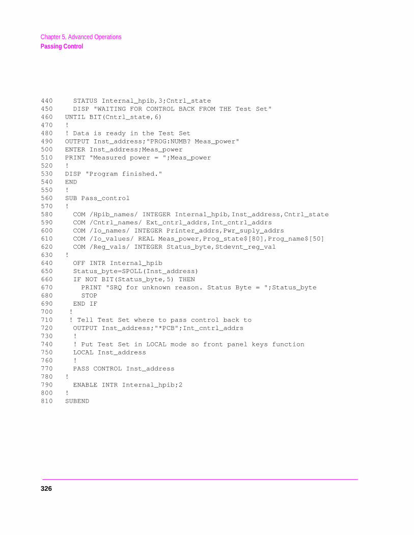
Chapter 5, Advanced OperationsPassing Control
440 STATUS Internal_hpib,3;Cntrl_state450 DISP "WAITING FOR CONTROL BACK FROM THE Test Set"460 UNTIL BIT(Cntrl_state,6)470 !480 ! Data is ready in the Test Set490 OUTPUT Inst_address;"PROG:NUMB? Meas_power"500 ENTER Inst_address;Meas_power510 PRINT "Measured power = ";Meas_power520 !530 DISP "Program finished."540 END550 !560 SUB Pass_control570 !580 COM /Hpib_names/ INTEGER Internal_hpib,Inst_address,Cntrl_state590 COM /Cntrl_names/ Ext_cntrl_addrs,Int_cntrl_addrs600 COM /Io_names/ INTEGER Printer_addrs,Pwr_suply_addrs610 COM /Io_values/ REAL Meas_power,Prog_state$[80],Prog_name$[50]620 COM /Reg_vals/ INTEGER Status_byte,Stdevnt_reg_val630 !640 OFF INTR Internal_hpib650 Status_byte=SPOLL(Inst_address)660 IF NOT BIT(Status_byte,5) THEN670 PRINT "SRQ for unknown reason. Status Byte = ";Status_byte680 STOP690 END IF700 !710 ! Tell Test Set where to pass control back to720 OUTPUT Inst_address;"*PCB";Int_cntrl_addrs730 !740 ! Put Test Set in LOCAL mode so front panel keys function750 LOCAL Inst_address760 !770 PASS CONTROL Inst_address780 !790 ENABLE INTR Internal_hpib;2800 !810 SUBEND
326
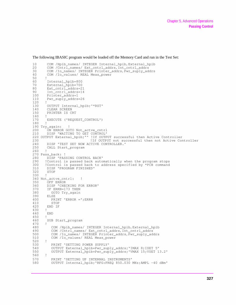
Chapter 5, Advanced OperationsPassing Control
The following IBASIC program would be loaded off the Memory Card and run in the Test Set:
10 COM /Hpib_names/ INTEGER Internal_hpib,External_hpib20 COM /Cntrl_names/ Ext_cntrl_addrs,Int_cntrl_addrs30 COM /Io_names/ INTEGER Printer_addrs,Pwr_suply_addrs40 COM /Io_values/ REAL Meas_power50 !60 Internal_hpib=80070 External_hpib=70080 Ext_cntrl_addrs=2190 Int_cntrl_addrs=14100 Printer_addrs=1110 Pwr_suply_addrs=26120 !130 OUTPUT Internal_hpib;"*RST"140 CLEAR SCREEN150 PRINTER IS CRT160 !170 EXECUTE ("REQUEST_CONTROL")180 !190 Try_again: !200 ON ERROR GOTO Not_actve_cntrl210 DISP "WAITING TO GET CONTROL"220 OUTPUT External_hpib;"" !If OUTPUT successful then Active Controller230 !If OUTPUT not successful then not Active Controller240 DISP "TEST SET NOW ACTIVE CONTROLLER."250 CALL Start_program260 !270 Pass_back: !280 DISP "PASSING CONTROL BACK"290 !Control is passed back automatically when the program stops300 !Control is passed back to address specified by *PCB command310 DISP "PROGRAM FINISHED"320 STOP330 !340 Not_actve_cntrl: !350 OFF ERROR360 DISP "CHECKING FOR ERROR"370 IF ERRN=173 THEN380 GOTO Try_again390 ELSE400 PRINT "ERROR =";ERRN410 STOP420 END IF430 !440 END450 !460 SUB Start_program470 !480 COM /Hpib_names/ INTEGER Internal_hpib,External_hpib490 COM /Cntrl_names/ Ext_cntrl_addrs,Int_cntrl_addrs500 COM /Io_names/ INTEGER Printer_addrs,Pwr_suply_addrs510 COM /Io_values/ REAL Meas_power520 !530 PRINT "SETTING POWER SUPPLY"540 OUTPUT External_hpib+Pwr_suply_addrs;"IMAX 8;ISET 5"550 OUTPUT External_hpib+Pwr_suply_addrs;"VMAX 15;VSET 13.2"560 !570 PRINT "SETTING UP INTERNAL INSTRUMENTS"580 OUTPUT Internal_hpib;"RFG:FREQ 850.030 MHz;AMPL -40 dBm"
327
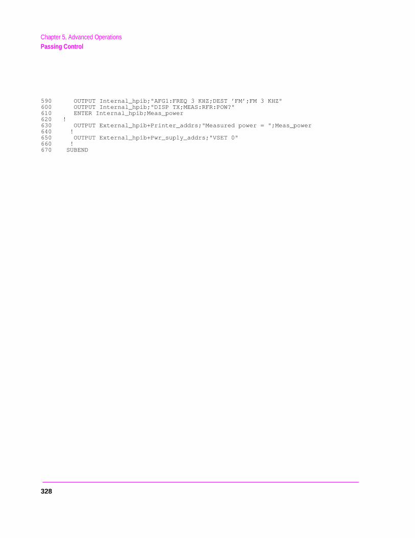
Chapter 5, Advanced OperationsPassing Control
590 OUTPUT Internal_hpib;"AFG1:FREQ 3 KHZ;DEST ’FM’;FM 3 KHZ"600 OUTPUT Internal_hpib;"DISP TX;MEAS:RFR:POW?"610 ENTER Internal_hpib;Meas_power620 !630 OUTPUT External_hpib+Printer_addrs;"Measured power = ";Meas_power640 !650 OUTPUT External_hpib+Pwr_suply_addrs;"VSET 0"660 !670 SUBEND
328

6
. The IC
Memory Cards/Mass Storage
This chapter contains information about using the mass storage devices available in the Test Set for storing and retrieving program and data files. Access to the mass storage devices in the Test Set was designed primarily for the built-in IBASIC Controller. The Test Set’s mass storage devices are not directly accessible by an external controllerprogramming examples used in this chapter apply only to the Test Set’s built-in IBASController.
NOTE: Indirect access to the Test Set’s mass storage devices is available through the PROGram:EXECute command. Refer to the Standard Commands for Programmable Instruments (SCPI) for generic information on the PROGram:EXECute command.
The IBASIC programming examples are provided to assist the programmer in understanding the use of the Test Set’s mass storage devices. They are not intended to be a comprehensive description of the IBASIC mass storage commands and procedures. For detailed information on IBASIC commands, refer to the HP Instrument BASIC User’s Handbook.
329
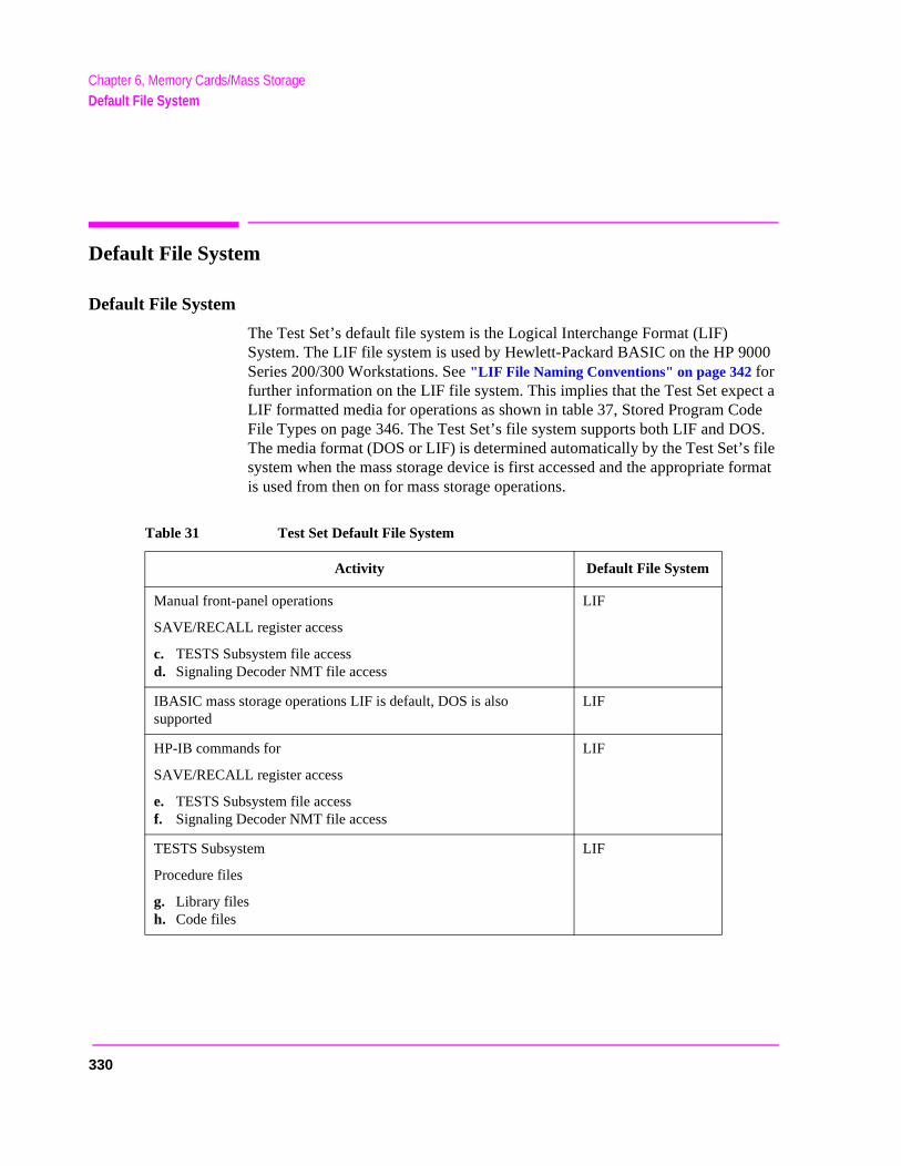
Chapter 6, Memory Cards/Mass StorageDefault File System
00
ct a de S.
file ormat
Default File System
Default File System
The Test Set’s default file system is the Logical Interchange Format (LIF) System. The LIF file system is used by Hewlett-Packard BASIC on the HP 90Series 200/300 Workstations. See "LIF File Naming Conventions" on page 342 for further information on the LIF file system. This implies that the Test Set expeLIF formatted media for operations as shown in table 37, Stored Program CoFile Types on page 346. The Test Set’s file system supports both LIF and DOThe media format (DOS or LIF) is determined automatically by the Test Set’ssystem when the mass storage device is first accessed and the appropriate fis used from then on for mass storage operations.
Table 31 Test Set Default File System
Activity Default File System
Manual front-panel operations
SAVE/RECALL register access
c. TESTS Subsystem file access d. Signaling Decoder NMT file access
LIF
IBASIC mass storage operations LIF is default, DOS is also supported
LIF
HP-IB commands for
SAVE/RECALL register access
e. TESTS Subsystem file accessf. Signaling Decoder NMT file access
LIF
TESTS Subsystem
Procedure files
g. Library filesh. Code files
LIF
330
Chapter 6, Memory Cards/Mass StorageMass Storage Device Overview
rnal
Test
TP
t Set.ROM)inserted
Mass Storage Device Overview
As shown in figure 19 on page 332, the Test Set has both internal and external mass storage devices. There are five types of mass storage devices in the Test Set:
• On-board random-access memory disk (RAM disk) located on the Test Set’s intememory board
• On-board read-only memory disk (ROM disk) located on the Test Set’s internal memory board
• External disk drives connected to the Test Set’s external HP-IB
• Internal static random access memory (SRAM) cards which are inserted into the Set’s front-panel Memory Card slot
• Internal read-only memory (ROM) cards (also called One-Time Programmable or Ocards) which are inserted into the Test Set’s front-panel Memory Card slot
NOTE: The hardware for reading-from and writing-to memory cards is located internal to the TesTherefore, the static random access memory (SRAM) cards and the read only memory (cards are considered internal to the Test Set even thought the physical media must be into the Test Set’s front-panel Memory Card slot.
331
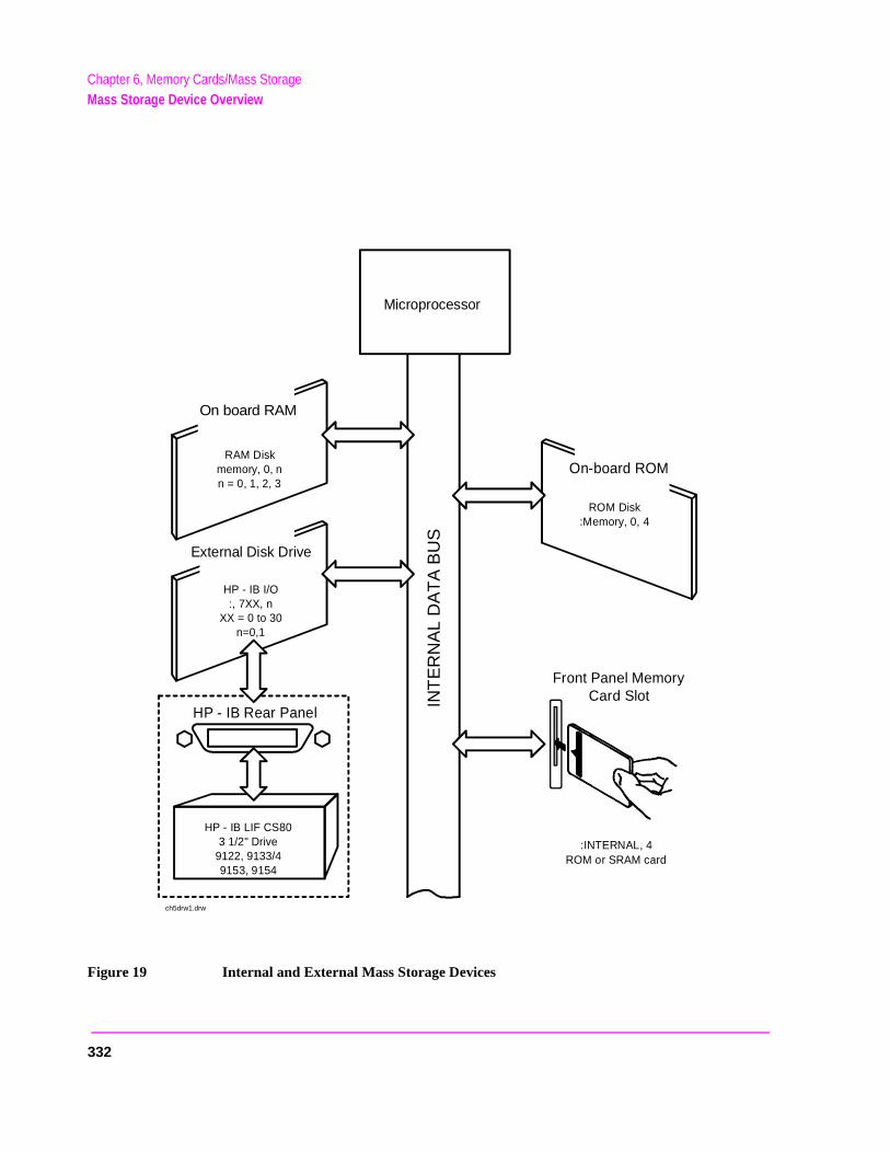
Chapter 6, Memory Cards/Mass StorageMass Storage Device Overview
Figure 19 Internal and External Mass Storage Devices
:INTERNAL, 4ROM or SRAM card
Remove SRAM card from test set.
INT
ER
NA
L D
AT
A B
US
ROM Disk:Memory, 0, 4
RAM Diskmemory, 0, nn = 0, 1, 2, 3
HP - IB I/O:, 7XX, n
XX = 0 to 30n=0,1
On board RAM
HP - IB Rear Panel
HP - IB LIF CS803 1/2" Drive
9122, 9133/49153, 9154
External Disk Drive
On-board ROM
Front Panel MemoryCard Slot
Microprocessor
ch5drw1.drw
332
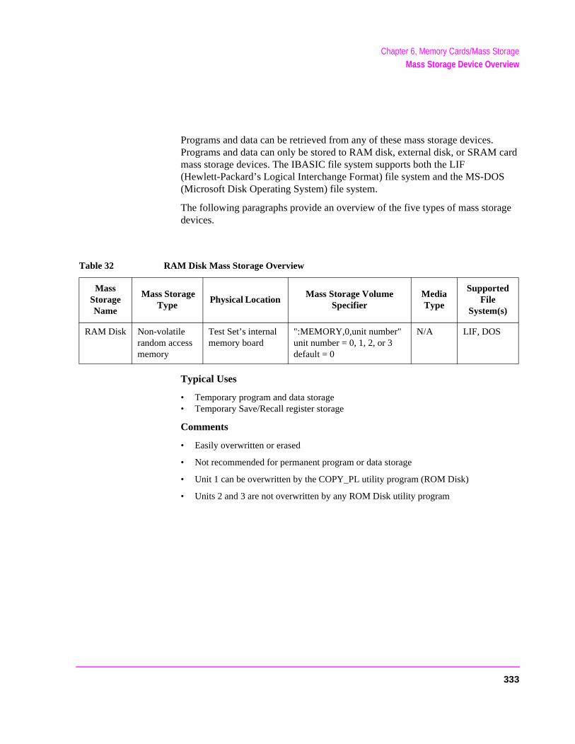
Chapter 6, Memory Cards/Mass StorageMass Storage Device Overview
ge
Programs and data can be retrieved from any of these mass storage devices. Programs and data can only be stored to RAM disk, external disk, or SRAM card mass storage devices. The IBASIC file system supports both the LIF (Hewlett-Packard’s Logical Interchange Format) file system and the MS-DOS(Microsoft Disk Operating System) file system.
The following paragraphs provide an overview of the five types of mass storadevices.
Typical Uses
• Temporary program and data storage • Temporary Save/Recall register storage
Comments
• Easily overwritten or erased
• Not recommended for permanent program or data storage
• Unit 1 can be overwritten by the COPY_PL utility program (ROM Disk)
• Units 2 and 3 are not overwritten by any ROM Disk utility program
Table 32 RAM Disk Mass Storage Overview
Mass Storage Name
Mass Storage Type
Physical Location Mass Storage Volume
Specifier Media Type
Supported File
System(s)
RAM Disk Non-volatilerandom accessmemory
Test Set’s internalmemory board
":MEMORY,0,unit number"unit number = 0, 1, 2, or 3 default = 0
N/A LIF, DOS
333
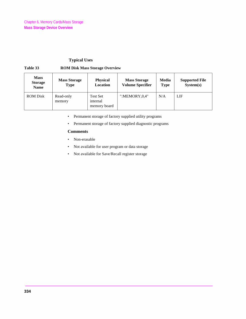
Chapter 6, Memory Cards/Mass StorageMass Storage Device Overview
Typical Uses
• Permanent storage of factory supplied utility programs
• Permanent storage of factory supplied diagnostic programs
Comments
• Non-erasable
• Not available for user program or data storage
• Not available for Save/Recall register storage
Table 33 ROM Disk Mass Storage Overview
MassStorageName
Mass StorageType
PhysicalLocation
Mass StorageVolume Specifier
MediaType
Supported FileSystem(s)
ROM Disk Read-onlymemory
Test Setinternal memory board
":MEMORY,0,4" N/A LIF
334
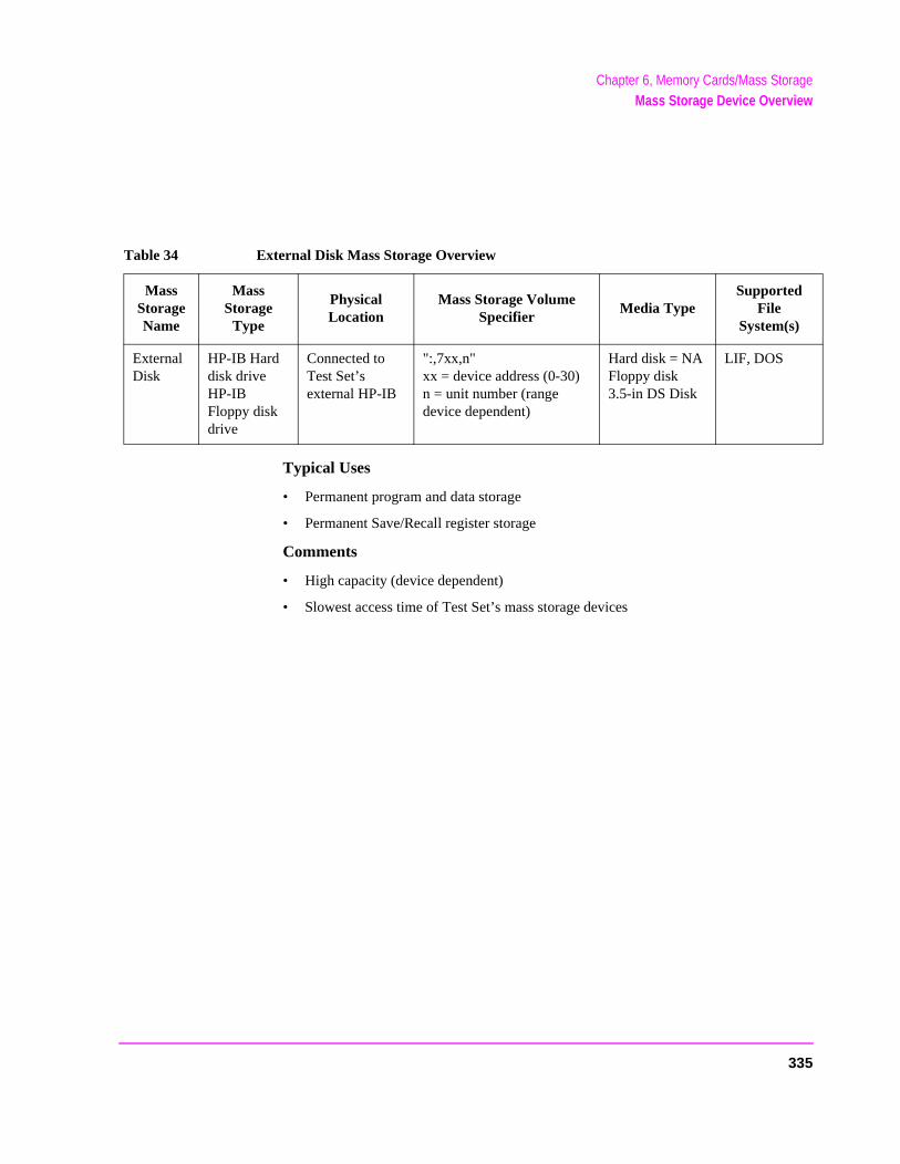
Chapter 6, Memory Cards/Mass StorageMass Storage Device Overview
Typical Uses
• Permanent program and data storage
• Permanent Save/Recall register storage
Comments
• High capacity (device dependent)
• Slowest access time of Test Set’s mass storage devices
Table 34 External Disk Mass Storage Overview
MassStorageName
MassStorage
Type
PhysicalLocation
Mass Storage VolumeSpecifier
Media TypeSupported
FileSystem(s)
External Disk
HP-IB Harddisk driveHP-IB Floppy disk drive
Connected toTest Set’sexternal HP-IB
":,7xx,n"xx = device address (0-30)n = unit number (range device dependent)
Hard disk = NA Floppy disk 3.5-in DS Disk
LIF, DOS
335
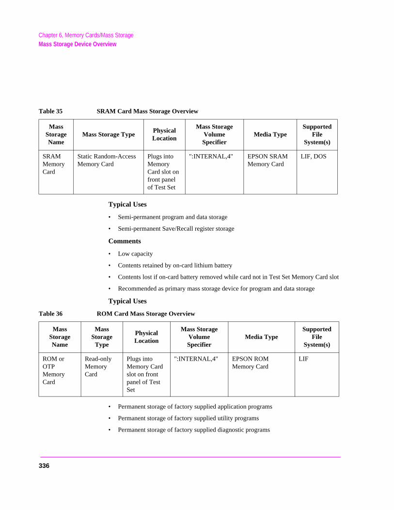
Chapter 6, Memory Cards/Mass StorageMass Storage Device Overview
slot
Typical Uses
• Semi-permanent program and data storage
• Semi-permanent Save/Recall register storage
Comments
• Low capacity
• Contents retained by on-card lithium battery
• Contents lost if on-card battery removed while card not in Test Set Memory Card
• Recommended as primary mass storage device for program and data storage
Typical Uses
• Permanent storage of factory supplied application programs
• Permanent storage of factory supplied utility programs
• Permanent storage of factory supplied diagnostic programs
Table 35 SRAM Card Mass Storage Overview
MassStorageName
Mass Storage Type PhysicalLocation
Mass StorageVolumeSpecifier
Media Type Supported
FileSystem(s)
SRAMMemoryCard
Static Random-AccessMemory Card
Plugs intoMemoryCard slot onfront panelof Test Set
":INTERNAL,4" EPSON SRAM Memory Card
LIF, DOS
Table 36 ROM Card Mass Storage Overview
MassStorageName
MassStorage
Type
PhysicalLocation
Mass StorageVolumeSpecifier
Media Type Supported
FileSystem(s)
ROM orOTPMemory Card
Read-onlyMemoryCard
Plugs into Memory Card slot on front panel of Test Set
":INTERNAL,4" EPSON ROM Memory Card
LIF
336

Chapter 6, Memory Cards/Mass StorageMass Storage Device Overview
Comments
• Non-erasable
• Not available for user program or data storage
• Not available for Save/Recall register storage
337
Chapter 6, Memory Cards/Mass StorageDefault Mass Storage Locations
et’s
cated
Default Mass Storage Locations
Built-in IBASIC Controller
The default mass storage location for the built-in IBASIC Controller is the front panel memory card slot (mass storage volume specifier ":INTERNAL,4") after any of the following conditions:
• power-up
• initializing RAM with the SERVICE screen’s RAM Initialize function
The mass storage location for the built-in IBASIC Controller can be changed using the MASS STORAGE IS command. Refer to the HP Instrument BASIC Users Handbook for further information on the MASS STORAGE IS command.
Save/Recall Registers
The default mass storage location for the Save/Recall registers is the Test Sinternal RAM (no mass storage volume specifier) after any of the following conditions:
• power-up
• initializing RAM with the SERVICE screen’s RAM Initialize function
• resetting the Test Set using the front-panel PRESET key
• resetting the Test Set using the *RST HP-IB Common Command
The mass storage location for Save/Recall registers can be changed using the Save/Recall field in the I/O CONFIGURE screen. The default mass storage volume specifiers for the Save/Recall register mass storage locations are as follows:
• Internal selection - (no mass storage volume specifier, registers are saved to alloRAM space)
• Card selection (not changeable) - ":INTERNAL,4"
• RAM selection (not changeable) - ":MEMORY,0,0"
• Disk selection - the External Disk Specification field in the TESTS (External Devices) screen.
338
Chapter 6, Memory Cards/Mass StorageDefault Mass Storage Locations
External Disk Drive
The default mass storage volume specifier for the external disk drive is set using the External Disk Specification field in the TESTS (External Devices) screen.
TESTS Subsystem
The default mass storage location for the TESTS Subsystem is set using the Select Procedure Location: field on the TESTS (Main Menu) screen. The default mass storage volume specifiers for the TESTS Subsystem mass storage locations are as follows:
• Card selection (not changeable) - ":INTERNAL,4"
• ROM selection (not changeable) - ":MEMORY,0,4"
• RAM selection (not changeable) - ":MEMORY,0,0"
• Disk selection - the External Disk Specification field in the TESTS (External Devices) screen.
Selecting the Mass Storage Location
The IBASIC mass storage location is selected using the IBASIC Mass Storage Is command. The mass storage volume specifier for the desired mass storage location is appended to the Mass Storage Is command. Refer to the HP Instrument BASIC User’s Handbook for further information regarding the Mass Storage Is command.
For example, to change the default mass storage location to RAM Disk unit 2, execute the following command:
Mass Storage Is ":MEMORY,0,2"
The Mass Storage Is command is keyboard and program executable; however, any changes made are lost when the Test Set is turned off or when the SERVICE screen’s RAM Initialize function is executed.
339

Chapter 6, Memory Cards/Mass StorageMass Storage Access
ns can
ram
ing cessed case
es are
st be
tions,
Mass Storage Access
Program and data files stored on the Test Set’s various mass storage locatiobe selectively accessed from the following screens:
• The TESTS (IBASIC Controller) screen.
Any type of file can be accessed from this screen, either through an IBASIC progor the IBASIC command line.
• The TESTS (Main Menu) screen using the Select Procedure Location: and Select Procedure Filename: fields.
Only procedure files shipped with HP 11807 software or procedure files created usthe TESTS (Save/Delete Procedure) screen of the TESTS Subsystem can be acusing these fields. When created, procedure file names are prefixed with a lowerp (pFM_TEST).
A corresponding code file - prefixed with a lower case c (cFM_TEST) on the - must reside on the same media for the procedure to work. Refer to the TESTS screendescription in the User’s Guide for further information on the TESTS Subsystem.
• The TESTS (Save/Delete Procedure) screen using the Select Procedure Location: and Enter Procedure Filename: fields.
This screen is used to create “procedure” files. When created, procedure file namprefixed with a lower case p (pFM_TEST).
• The Signaling Decoder screen in NMT mode.
Only user-written NMT tests can be accessed from this screen. NMT test files musaved with a lower case n prefix (nNMT_1) on the Test Set.
Save/Recall register files, stored on the Test Set’s various mass storage locacan be accessed using the front-panel SAVE and RECALL keys.
340

Chapter 6, Memory Cards/Mass StorageDOS and LIF File System Considerations
DOS and LIF File System Considerations
Program and data files can be stored and retrieved from IBASIC using either the DOS or LIF file system. The media format (DOS or LIF) is determined automatically by the IBASIC file system when the mass storage device is first accessed, and the appropriate format is used from then on. DOS and LIF use different file naming conventions. In addition, the Test Set uses certain file naming conventions which are unique to the Test Set. Unexpected file operation can occur if proper consideration is not given to the file naming conventions.
341
Chapter 6, Memory Cards/Mass StorageDOS and LIF File System Considerations
ith HPrage
File Naming Conventions
LIF File Naming Conventions
The LIF file system is used by Hewlett-Packard BASIC on the HP 9000 Series 200/300 Workstations. It is a flat file system, which means that it has no subdirectories. The LIF file system allows up to 10-character file names which are case sensitive. The LIF file system preserves the use of uppercase and lowercase characters for file storage and retrieval. For example, the file names File1, FILE1, file1 and FiLe1 could represent different files. LIF files cannot start with a space, and any file name longer than 10 characters is considered an error.
NOTE: The Test Set’s file system does not support the HFS (hierarchical file system) used wBASIC. Therefore, no directory path information can be used during mass stooperations with LIF files.
DOS File Naming Conventions
The DOS file system is used on IBM compatible personal computers. The DOS file system is hierarchical, which means it supports subdirectories. The DOS file system allows up to 8-character file names with an optional extension of up to 3 characters. The file name is separated from the extension (if it exists) with a period (.). DOS file names are case independent. The characters are stored as upper case ASCII in the DOS directory but the files may be referenced without regard to case. The DOS file system always converts any lowercase characters to uppercase when files are stored. For example, the file names File1 , FILE1 , file1 and FiLe1 all represent the single DOS file FILE1 .
The period (.) may appear in the name but only to separate the file name from the extension. The period is not considered part of the file name itself. If the name portion of a DOS file name is longer than 8 characters, it is truncated to 8 characters and no error is generated. Similarly, if the extension is longer than 3 characters, it is truncated to 3 characters and no error is given.
342

Chapter 6, Memory Cards/Mass StorageDOS and LIF File System Considerations
s:
ile
hen
the stem
ed
g
into to ields
ms to a m.
Test Set File Naming Conventions
The Test Set’s TESTS Subsystem uses the following file naming convention
• The c prefix is used to indicate a code file and is automatically prefixed onto the fname when the program code file is stored for use by the TESTS susbsystem.
• The p prefix is used to indicate a procedure file and is prefixed onto the file name wthe file is stored by the TESTS Subsystem
• The l prefix is used to indicate a library file and is prefixed onto the file name whenfile is created by the Program Development System for use with the TESTS Subsy
The Test Set’s Save/Recall register subsystem uses the following file namingconvention:
The _ prefix is used to indicate a stored Save/Recall register file and is prefixonto the file name when the file is created .
The Test Set’s Signaling Decoder in NMT mode uses the following file naminconvention:
The n prefix is used to indicate a stored NMT file and is prefixed onto the file name when the file is created .
Test Set File Entry Field Width
The TESTS Subsystem and the Save/Recall register subsystem have fields which the operator enters a file name. These fields are used by the operatorenter the name of a file to be stored or loaded. The files accessed by these fhave a one-character prefix of c, p, l, or _. The width of these fields is 9 characters. The prefix character + 9 characters = 10 characters, which conforthe LIF file system’s naming convention. Consequently these fields will hold file name which is longer than the 8 characters allowed by the DOS file syste
343

Chapter 6, Memory Cards/Mass StorageDOS and LIF File System Considerations
ion).
) is ning
ill
) is If the wing
) is ning
ill
de, or riod) ecall the
, code, ix
code,
han tted ld is le is
Potential File Name Conflicts
Unexpected file operation can occur if proper consideration is not given to the different file system naming conventions and the Test Set file entry field width.
• A full DOS file name is 12 characters (8 character file name + . + 3 character extensA full DOS file name will not fit in the Test Set’s file entry field.
Trying to store a file to a LIF formatted media with a DOS file name that contains anextension will generate ERROR 53 Improper file name.
• On a DOS formatted disk, any file beginning with the letter c (upper or lower caseconsidered a TESTS Subsystem code file. On a LIF formatted disk any file beginwith a lower case c is considered a TESTS Subsystem code file. If the TESTS Subsystem attempts to retrieve a file which is not a code file, the following error wbe generated: Error reading code file. Check file and media.
• On a DOS formatted disk, any file beginning with the letter p (upper or lower caseconsidered a TESTS Subsystem procedure file. On a LIF formatted disk, any filebeginning with a lower case p is considered a TESTS Subsystem procedure file. TESTS Subsystem attempts to retrieve a file which is not a procedure file, the folloerror will be generated: Error reading procedure file. Check file and media.
• On a DOS formatted disk, any file beginning with the letter l (upper or lower caseconsidered a TESTS Subsystem library file. On a LIF formatted disk, any file beginwith a lower case l is considered a TESTS Subsystem library file. If the TESTS Subsystem attempts to retrieve a file which is not a library file, the following error wbe generated: Error reading library file. Check file and media.
When reading files from mass storage to either the TESTS Subsystem (procedure, colibrary files) or the Save/Recall register Subsystem, the Test Set interprets the “.” (peas a delimiter and ignores any following characters. If TESTS Subsystem or Save/Rregister subsystem files are stored to a DOS formatted media using file extensions, extensions will be stripped off by the Test Set before displaying the file in the file list.
• When reading files from mass storage to either the TESTS Subsystem (procedureor library files) or the Save/Recall register subsystem, the Test Set strips the prefcharacter (c, p, l, _) off the file name before displaying the file in the file list.
• When storing files to mass storage from either the TESTS Subsystem (procedure,or library files) or the Save/Recall register subsystem, the Test Set puts the prefixcharacter (c, p, l, _) onto the file name, making the file name 1 character longer tthat displayed in the file name entry field. If the file is being stored to a DOS formamedia (8-character file name) and the file name specified in the file name entry fie8 characters (ABCDEFGH) the last character will be silently truncated when the fistored (PABCDEFG).
344
Chapter 6, Memory Cards/Mass StorageDOS and LIF File System Considerations
y ld
-lt in
or
wer
wer
r
ESTS This ed
• When copying LIF named files to a DOS formatted media, the file name is silentltruncated to 8 characters since DOS only allows 8-character file names. This couresult in ERROR 54 Duplicate File Name.
When storing or deleting files to a DOS formatted media, the file name is silently truncated to 8 characters since DOS only allows 8-character file names. This could resuERROR 54 Duplicate File Name.
File Naming Recommendations
If switching between media types (DOS and LIF) or operating exclusively in DOS the following naming conventions are recommended.
• Ensure that only TESTS Subsystem procedure files begin with the letter p (upperlower case).
• Ensure that only TESTS Subsystem library files begin with the letter l (upper or locase).
• Ensure that only TESTS Subsystem code files begin with the letter c (upper or locase).
• Ensure that only user-written NMT test files begin with the letter n (upper or lowecase).
• Avoid using DOS file extensions.
If possible, only use file names of 7 characters or less for Save/Recall registers or TSubsystem files (prefix character + 7 characters = 8-character DOS file name limit). will avoid silent truncation of file names which leads to many of the problems discussunder "Potential File Name Conflicts" on page 344.
345
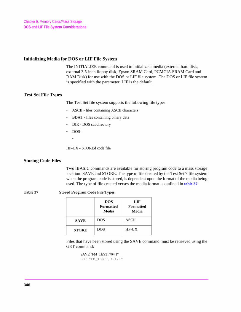
Chapter 6, Memory Cards/Mass StorageDOS and LIF File System Considerations
tem being
g the
Initializing Media for DOS or LIF File System
The INITIALIZE command is used to initialize a media (external hard disk, external 3.5-inch floppy disk, Epson SRAM Card, PCMCIA SRAM Card and RAM Disk) for use with the DOS or LIF file system. The DOS or LIF file system is specified with the parameter. LIF is the default.
Test Set File Types
The Test Set file system supports the following file types:
• ASCII - files containing ASCII characters
• BDAT - files containing binary data
• DIR - DOS subdirectory
• DOS -
•
HP-UX - STOREd code file
Storing Code Files
Two IBASIC commands are available for storing program code to a mass storage location: SAVE and STORE. The type of file created by the Test Set’s file syswhen the program code is stored, is dependent upon the format of the media used. The type of file created verses the media format is outlined in table 37.
Files that have been stored using the SAVE command must be retrieved usinGET command:
SAVE "FM_TEST:,704,1"GET "FM_TEST:,704,1"
Table 37 Stored Program Code File Types
DOS Formatted
Media
LIF Formatted
Media
SAVE DOS ASCII
STORE DOS HP-UX
346
Chapter 6, Memory Cards/Mass StorageDOS and LIF File System Considerations
st
n a
Files that have been stored using the STORE command must be retrieved using the LOAD command:
STORE "FM_TEST:,704,1"LOAD "FM_TESTS:,704,1"
TESTS Subsystem DOS File Restrictions
The Test Set uses IBASIC revision 1.0. The IBASIC 1.0 file system cannot distinguish between DOS files that have been “SAVEd” and those that were “STOREd.” As shown in table 37 on page 346, SAVE and STORE both produce afile type DOS. This can result in undesired operation when trying to run a Teprocedure from the TESTS (Main Menu) screen.
The process for running a Test Procedure is described below. The potential problem is described in step 3.
1. The procedure file location is selected using the Select Procedure Location: field.
2. The desired procedure file is selected using the Select Procedure Filename: field. When the procedure file is selected, the Test Set loads the specified procedure file into memory. One of the pieces of information in the procedure file is the name of the code file used with that procedure.
3. The Run Test softkey is selected. When the Run Test softkey is selected the Test Set attempts to load the code file into memory. If the code file is located on a DOS formatted media the Test Set will attempt to GET the file (the Test Set assumes the file was stored using the SAVE command). If the code file was stored to the DOS formatted media using the STORE command an ERROR 58 Improper file type is generated.
If an ERROR 58 Improper file type is generated the code file must be loaded into memory and then stored back to mass storage using the SAVE command as follows:
1. Access the TESTS (IBASIC Controller) screen and LOAD the code file into the Test Set.
2. Delete the stored code file from the mass storage location using the IBASIC PURGE command.
3. SAVE the program as a Code file, using a lower-case c as a prefix, to the same mass storage location as the original code file.
The IBASIC 1.0 file system can distinguish between LIF files that have been “SAVEd” and those that were “STOREd.” Consequently the Test Set can determine whether to use a GET or a LOAD on a code file which is located oLIF formatted media.
347
Chapter 6, Memory Cards/Mass StorageUsing the ROM Disk
Using the ROM Disk
The Test Set comes with several Test Procedures stored on the internal ROM disk. These Test procedures provide instrument diagnostic utilities, periodic calibration utilities, memory management utilities, a variety of general purpose utilities, and several IBASIC demonstration programs.
To see a brief description of what each procedure does perform the following steps:
1. Display the TESTS (Main Menu) screen by selecting the front-panel TESTS key.
2. Using the rotary knob, select the Select Procedure Location: field and choose ROM from the choices.
3. Using the rotary knob, select the Select Procedure Filename field. A list of Test Procedures stored on the ROM disk is displayed in the Choices: field. Using the rotary knob, select the Test Procedure of interest.
4. A brief description of the Test Procedure will be displayed in the Description field.
ROM DISK cannot be written to for user storage.
The ROM Disk’s mass storage volume specifier is ":MEMORY,0,4"
For example: to catalogue the contents of the ROM Disk from the TESTS (IBASIC Controller) screen enter:
30 OUTPUT 814;"AFAN:DEMP:GAIN 20 dB"
348
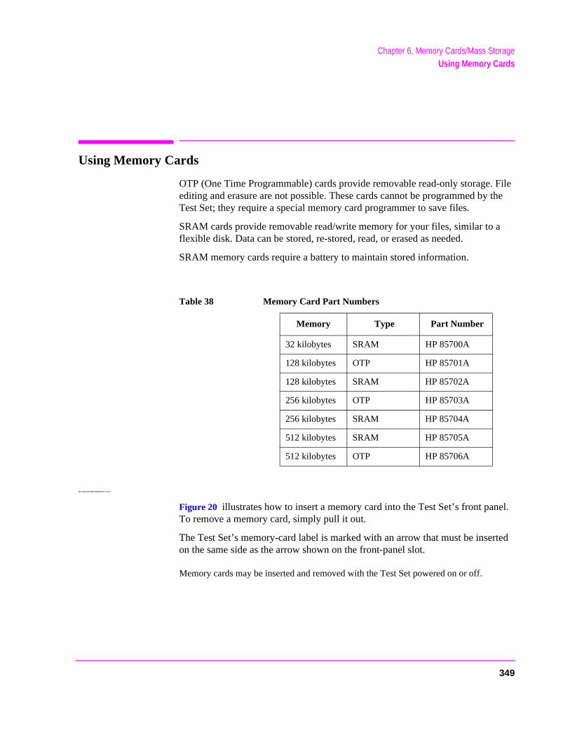
Chapter 6, Memory Cards/Mass StorageUsing Memory Cards
el.
rted
Using Memory Cards
OTP (One Time Programmable) cards provide removable read-only storage. File editing and erasure are not possible. These cards cannot be programmed by the Test Set; they require a special memory card programmer to save files.
SRAM cards provide removable read/write memory for your files, similar to a flexible disk. Data can be stored, re-stored, read, or erased as needed.
SRAM memory cards require a battery to maintain stored information.
Inserting and Removing Memory Cards
Figure 20 illustrates how to insert a memory card into the Test Set’s front panTo remove a memory card, simply pull it out.
The Test Set’s memory-card label is marked with an arrow that must be inseon the same side as the arrow shown on the front-panel slot.
Memory cards may be inserted and removed with the Test Set powered on or off.
Table 38 Memory Card Part Numbers
Memory Type Part Number
32 kilobytes SRAM HP 85700A
128 kilobytes OTP HP 85701A
128 kilobytes SRAM HP 85702A
256 kilobytes OTP HP 85703A
256 kilobytes SRAM HP 85704A
512 kilobytes SRAM HP 85705A
512 kilobytes OTP HP 85706A
349
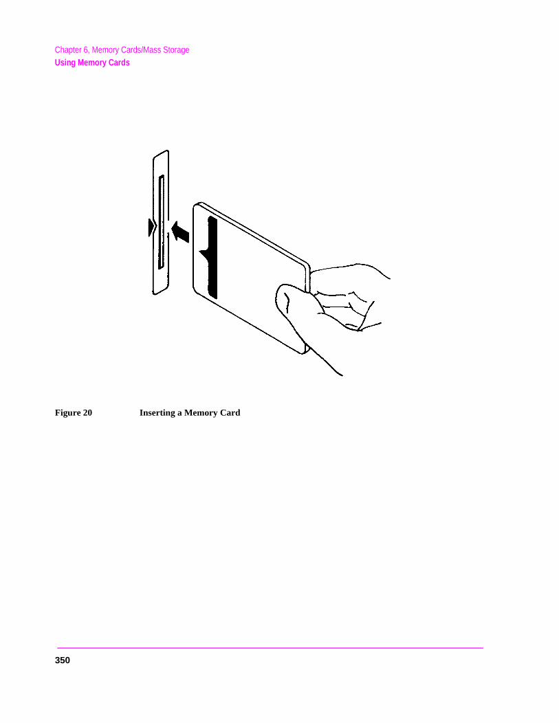
Chapter 6, Memory Cards/Mass StorageUsing Memory Cards
Figure 20 Inserting a Memory Card
350
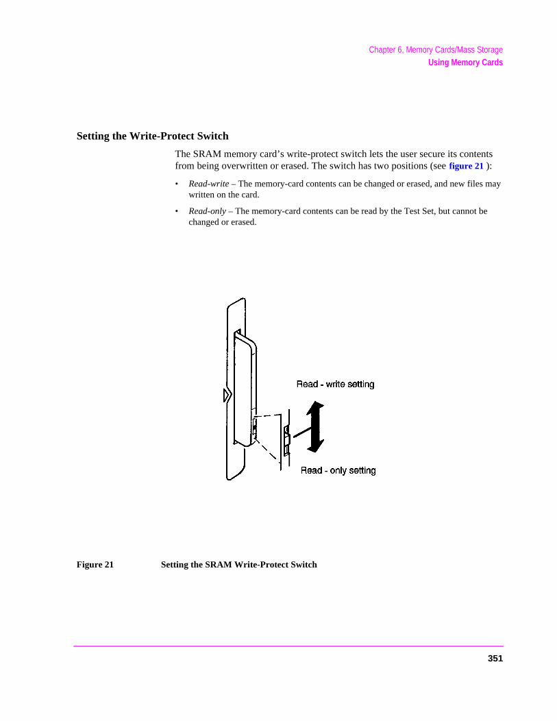
Chapter 6, Memory Cards/Mass StorageUsing Memory Cards
ts
may
e
Setting the Write-Protect Switch
The SRAM memory card’s write-protect switch lets the user secure its contenfrom being overwritten or erased. The switch has two positions (see figure 21 ):
• Read-write – The memory-card contents can be changed or erased, and new fileswritten on the card.
• Read-only – The memory-card contents can be read by the Test Set, but cannot bchanged or erased.
Figure 21 Setting the SRAM Write-Protect Switch
351
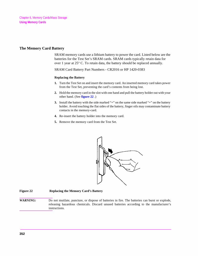
Chapter 6, Memory Cards/Mass StorageUsing Memory Cards
r
your
ttery tery
turer’s
The Memory Card Battery
SRAM memory cards use a lithium battery to power the card. Listed below are the batteries for the Test Set’s SRAM cards. SRAM cards typically retain data foover 1 year at 25° C. To retain data, the battery should be replaced annually.
SRAM Card Battery Part Numbers - CR2016 or HP 1420-0383
Replacing the Battery
1. Turn the Test Set on and insert the memory card. An inserted memory card takes power from the Test Set, preventing the card’s contents from being lost.
2. Hold the memory card in the slot with one hand and pull the battery holder out with other hand. (See figure 22 .)
3. Install the battery with the side marked “+” on the same side marked “+” on the baholder. Avoid touching the flat sides of the battery, finger oils may contaminate batcontacts in the memory-card.
4. Re-insert the battery holder into the memory card.
5. Remove the memory card from the Test Set.
Figure 22 Replacing the Memory Card’s Battery
WARNING: Do not mutilate, puncture, or dispose of batteries in fire. The batteries can burst or explode,releasing hazardous chemicals. Discard unused batteries according to the manufacinstructions.
352
Chapter 6, Memory Cards/Mass StorageUsing Memory Cards
IC
torage o e with .
be
has
to
Memory Card Mass Storage Volume Specifier
The front-panel memory card slot’s mass storage volume specifier is ":INTERNAL,4" and is the default mass storage device for the Test Set. For example, to catalogue the contents of a memory card from the TESTS (IBASController) screen, execute the following IBASIC command:
C376AT ":INTERNAL,4"
or, if the mass storage location has not been changed,
CAT
If the MSI (Mass Storage Is) command has been used to change the mass slocation to a different device, the ":INTERNAL,4" designation must be used taccess the memory card slot. Any changes to the mass storage location madthe MSI (Mass Storage Is) command are lost when the Test Set is turned off
Memory Card Initialization
All new SRAM cards must be initialized before they can be used to store information. The RAM_MNG procedure stored on the internal ROM Disk canused to quickly initialize any SRAM memory card.
SRAM Memory Cards can also be initialized from the TESTS (IBASIC Controller) screen by inserting the memory card into the front-panel slot and executing the following IBASIC command:
INITIALIZE "<volume type>:INTERNAL,4"
where the <volume type> can be LIF or DOS. To verify that the memory cardbeen properly initialized, execute the IBASIC command:
CAT ":INTERNAL,4"
If the error message ERROR 85 Medium uninitialized appears on the screenthe memory card has not been properly initialized. Check the SRAM battery ensure that it’s charged and inserted correctly in the battery holder.
353
Chapter 6, Memory Cards/Mass StorageBacking Up Procedure and Library Files
ory m type
ke and les.
Backing Up Procedure and Library Files
Making a backup copy of procedure and library files helps guard against file loss due to memory card (or battery) failure.
Using the COPY_PL ROM Program
The COPY_PL procedure on the internal ROM Disk will make backup copies of TESTS Subsystem’s Procedure and Library files onto a second SRAM memcard, and can also initialize an uninitialized SRAM memory card. This progradoes not make backup copies of TESTS Subsystem’s code files, or copy anyof file to OTP memory cards.
The COPY_PL procedure is designed for use with HP 11807 software to mabackup copies of Hewlett-Packard supplied TESTS Subsystem’s Procedure Library files or user-generated TESTS Subsystem’s Procedure and Library fi
To run COPY_PL:
1. Access the TESTS (Main Menu) screen.
2. Select the Select Procedure Location: field and choose ROM.
3. Select the Select Procedure Filename: field and select COPY_PL.
4. Select the Run Test softkey to start the procedure.
5. Follow the displayed instructions.
354
Chapter 6, Memory Cards/Mass StorageCopying Files Using IBASIC Commands
ory
Copying Files Using IBASIC Commands
Files can be copied from one mass storage device to another using the IBASIC COPY command. For example, to copy a file from a memory card to the left drive of an external dual-disk drive with a mass storage volume specifier of ":,702,0", execute the following IBASIC command from the TESTS (IBASIC Controller) command line:
COPY "FM_TEST:INTERNAL,4" TO "FM_TEST:,704,0"
“Stored” or “saved” files on one memory card can be copied to another memcard as follows:
• Insert the memory card containing the file to be copied.
• LOAD or GET1 the desired file from the memory card into the Test Set .
• Remove the original memory card.
• Insert the destination memory card in the Test Set.
• STORE or SAVE1 the file to the destination memory card.
1. See "Storing Code Files" on page 346 for information about the LOAD, GET, STORE, and SAVE commands.
Copying an Entire Volume
An entire volume can be copied from one mass storage device to the same type of mass storage device using the volume copy form of the COPY command. The destination volume must be as large as, or larger than, the source volume. The directory and any files on the destination volume are destroyed. The directory size on the destination volume becomes the same size as the source media. Disc-to-disc copy time is dependent on the mass storage device type. The volume copy form of the COPY command was designed to copy like-media to like-media and like-file-systems to like-file-systems. For example, to copy the entire contents of one internal RAM disk to another internal RAM disk, execute the following IBASIC command from the TESTS (IBASIC Controller) command line:
COPY ":MEMORY,0,0" TO ":MEMORY,0,1"
355
Chapter 6, Memory Cards/Mass StorageCopying Files Using IBASIC Commands
NOTE: Using the volume copy form of the COPY command can produce unexpected results. For example, using the volume copy form to copy the contents of a 64 Kbyte SRAM card to an external HP-IB 630-KByte floppy disk will result in the external floppy disk having a capacity of only 64 Kbyte when the volume copy is finished. Furthermore all files on the floppy disk before the volume copy was executed will be lost and are not recoverable. Additionally, the file system type on the source media (LIF or DOS) is forced onto the destination media. Caution should be exercised when using the volume copy form of the COPY command.
The Test Set only supports the following types of volume copy using the volumecopy form of the COPY command:
1. Like- media to like-media (RAM disk to RAM disk, external floppy to external floppy, and so forth)
2. Like-file-system to like-file-system (DOS to DOS, LIF to LIF)
All other types of volume copy are unsupported and will produce unexpected results or system errors.
Using wildcards in the COPY command can eliminate the need to use the volume form of the COPY command. Refer to the HP Instrument BASIC User’s Handbook for further information on wildcards and their use in the COPY command.
356
Chapter 6, Memory Cards/Mass StorageUsing RAM Disk
set n rased,
as a ts.
.
1, 2,
Using RAM Disk
RAM Disk is a section of the Test Set’s internal RAM memory that has been aside for use as a mass storage device. RAM Disk acts much the same as aexternal disk drive; that is, program and data files can be stored, re-stored, eand retrieved from the RAM Disk.
The RAM Disk is partitioned into four separate units: 0-3. Each unit is treatedseparate “disk.” The size of each disk can be specified in 256-byte incremen
The four RAM Disk units are designated ":MEMORY,0,0" to ":MEMORY,0,3"For example, to catalog the contents of RAM Disk unit “0” from the TESTS (IBASIC Controller) screen, execute the following command:
CAT ":MEMORY,0,0"
Volume 0’s contents can be viewed and loaded from the TESTS (IBASIC Controller) screen, the TESTS (Main Menu) screen, the TESTS (Save/DeleteProcedure) screen and the Signaling Decoder screen in NMT mode. Volumesand 3 can only be accessed from the TESTS (IBASIC Controller) screen.
NOTE: RAM Disk Erasure. The contents of RAM Disk are easily lost. Unit 0 can be overwrittenby the RAM_MNG utility program (ROM Disk). Unit 1 can be overwritten by theCOPY_PL utility program (ROM Disk). The contents of all units are lost when theSERVICE screen’s RAM Initialize function is executed. Therefore, RAM Diskshould only be used for non-permanent, short-term storage of program or data files.
357
Chapter 6, Memory Cards/Mass StorageUsing RAM Disk
Initializing RAM Disks
Each RAM Disk unit must be initialized before it can be used. Unit 0 can be initialized using the RAM_MNG procedure stored on internal ROM Disk. Volumes 1, 2, and 3 must be initialized from the TESTS (IBASIC Controller) screen.
The optional “unit size” parameter in the following procedure specifies the memory area, in 256 byte blocks, set aside for each disk unit.
Follow these steps to initialize volumes 1, 2, or 3:
1. Access the TESTS (IBASIC Controller) screen.
2. Using the rotary knob or an external terminal, enter and execute the IBASIC command:
INITIALIZE ":MEMORY,0,<unit number 1-3>",<unit size>
For example:
INITALIZE ":MEMORY,0,1",50
358
Chapter 6, Memory Cards/Mass StorageUsing External Disk Drives
Set.
the
Using External Disk Drives
The Test Set supports only HP-IB external disk drives. Certain configuration information is required by the Test Set to access external disk drives.
The I/O CONFIGURE screen’s HP-IB Mode field must be set to Control any timean external disk drive is used by the Test Set.
To load files from the TESTS screens or NMT Signaling Decoder screen, thedisk’s mass storage volume specifier must be entered in the External Disk Specification field on the TESTS (External Devices) screen (for example,:,702,1).
Initializing External Disks
All new external disk media must be initialized before it can be used to store information. External disk media can be initialized for either LIF (Logical Interchange Format) or DOS (Disk Operating System) format using the Test (See "DOS and LIF File System Considerations" on page 341.)
External disk media can be initialized from the TESTS (IBASIC Controller) screen by inserting the new media into the external disk drive and executingfollowing IBASIC command:
INITIALIZE "<volume type>:<external disk mass storage volume specifier>"
where the <volume type> can be LIF or DOS
For example:
INITIALIZE "DOS:,702,1").
To verify that disk media has been properly initialized, execute the IBASIC command:
CAT "<external disk mass storage volume specifier>"
For example:
CAT ":,702,1"
359

Chapter 6, Memory Cards/Mass StorageUsing External Disk Drives
360
7
IBASIC Controller
361
Chapter 7, IBASIC ControllerIntroduction
ure.
ain is Set’s m
r
ded o IC
Introduction
The Test Set contains an instrument controller that can run programs to control the various instruments in the Test Set and instruments/devices connected to the Test Set’s external I/O ports (HP-IB, serial and parallel). Refer to "Overview of the Test Set" on page 28 for a complete description of the Test Set’s hardware architect
The instrument controller runs a subset of the Hewlett-Packard Rocky MountBASIC programming language called Instrument BASIC or IBASIC. Using thprogramming language it is possible to develop programs which use the Testinstruments to automatically test a variety of radios. Software is available froHewlett-Packard, the HP 11807 series, for testing the major radio systems currently in use today. Users can also develop their own IBASIC programs foautomated radio testing.
This chapter is designed to provide the programmer with the information neeto develop IBASIC programs for use on the built-in IBASIC controller. Refer tthe individual HP 11807 software manuals for information on using the IBAScontroller with Hewlett-Packard supplied software.
362
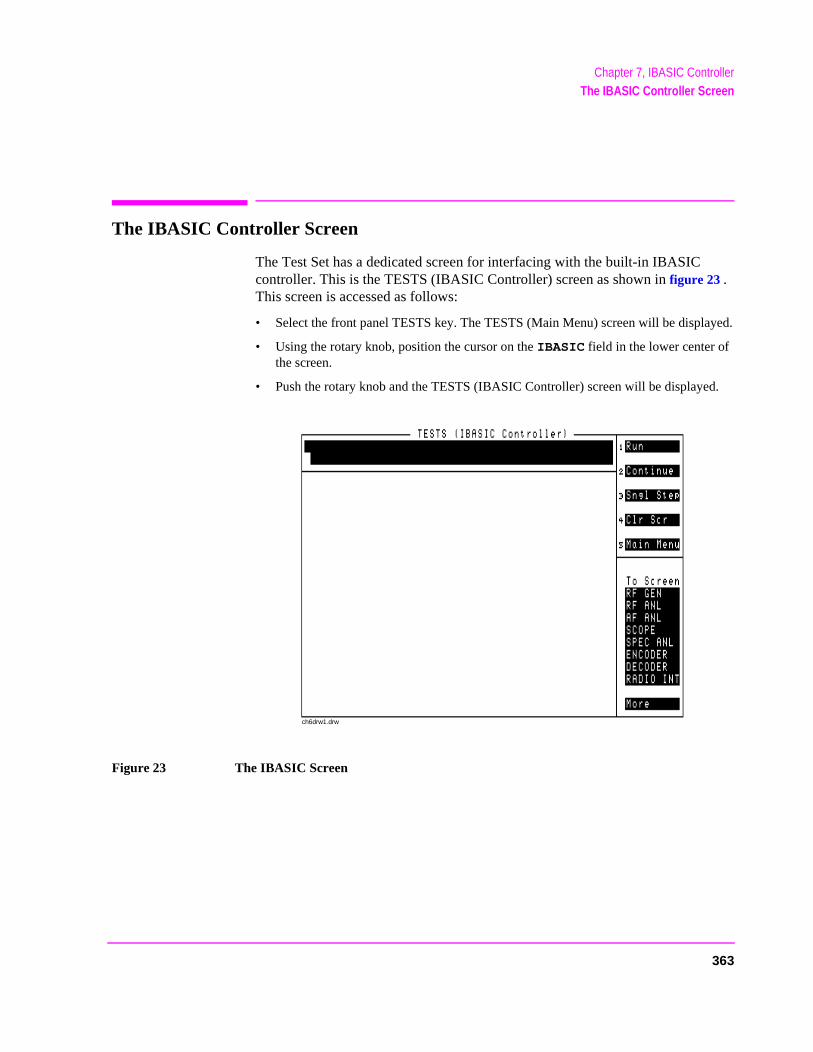
Chapter 7, IBASIC ControllerThe IBASIC Controller Screen
yed.
d.
The IBASIC Controller Screen
The Test Set has a dedicated screen for interfacing with the built-in IBASIC controller. This is the TESTS (IBASIC Controller) screen as shown in figure 23 . This screen is accessed as follows:
• Select the front panel TESTS key. The TESTS (Main Menu) screen will be displa
• Using the rotary knob, position the cursor on the IBASIC field in the lower center of the screen.
• Push the rotary knob and the TESTS (IBASIC Controller) screen will be displaye
Figure 23 The IBASIC Screen
ch6drw1.drw
363

Chapter 7, IBASIC ControllerThe IBASIC Controller Screen
The TESTS (IBASIC Controller) screen can be accessed programmatically by sending the following command:
OUTPUT 714;"DISP TIBasic"
The TESTS (IBASIC Controller) screen is divided into several areas which are used by the IBASIC controller for different purposes.
The small horizontal rectangle at the top left is the IBASIC command line. As the name implies IBASIC commands can be executed from this line. Commands can be entered locally using the rotary knob or remotely using serial port 9. A maximum of 100 characters may be entered into the command line.
The vertical rectangle at the top right side is the softkey label area. The five highlighted areas within the softkey label area correspond to the five special function keys on the front panel of the Test Set. IBASIC programs can assign tables to these keys and control program execution by using ON KEY interrupts.
The vertical rectangle at the bottom right side is the To Screen area and is the same as the To Screen area displayed on any other Test Set screen. The user may switch to some other Test Set screen by using the rotary knob to position the cursor onto the desired screen and then pushing the knob.
The large rectangle in the center of the screen is the CRT (display screen) for the IBASIC controller. The IBASIC controller uses this area for, displaying alpha, numeric, and graphic information, program editing, program listing and so forth. This area operates as would the CRT on an external Hewlett-Packard 9000 Series 200/300 Workstation.
364
Chapter 7, IBASIC ControllerImportant Notes for Program Development
licate
ke a
panel R).
STSortingcture..
Important Notes for Program Development
The Test Set is designed to operate the same way under automatic control as it does under manual control. This has several implications when designing and writing programs for the Test Set:
• To automate a particular task, determine how to do the task manually and then dupthe steps in the program.
• In Manual Control mode, a Test Set function must be displayed and “active” to mameasurement or receive DUT data. Therefore, to make a measurement using anIBASIC program, follow these basic steps:
1. Use the DISPlay command to select the screen for the instrument whose front contains the desired measurement result or data field (such as AF ANALYZE
2. Set the measurement field (such as SINAD) to the ON state.
3. Trigger a reading.
4. Read the result.
NOTE: The following sections discuss developing IBASIC programs which do not use the TESubsystem. Programs written for the TESTS Subsystem require the creation of suppLibrary, Procedure, and Code files, and must be written using a specific program struThe HP 11807A Radio Test Software packages are examples of this type of program
Refer to the "Writing Programs For the TESTS Subsystem" on page 437 forinformation on writing programs for the TESTS Subsystem.
365

Chapter 7, IBASIC ControllerProgram Development
Program Development
There are three recommended approaches for developing IBASIC programs. They are outlined in figure 24 and discussed in more detail later in this chapter. Since the Test Set only has the rotary knob and numeric keypad for data/character entry, developing programs on the Test Set alone is not recommended. All three development methods employ an external computer or terminal. The choice of development method will typically be driven by available equipment and extent of development task. If the development task is large, it is strongly recommended that a BASIC language computer be used as outlined in development Method #1.
Method #2 is recommended for large program modification or smaller program development. Method #2 uses an external PC or terminal as the CRT and keyboard for the built-in IBASIC controller.
Method #3 is least preferred for program development or modification because no syntax checking occurs until the program is first run making it difficult to debug long programs. Details of each development method are given later in this chapter.
366
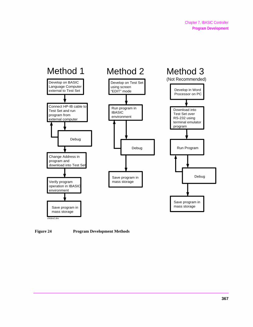
Chapter 7, IBASIC ControllerProgram Development
Figure 24 Program Development Methods
Develop on Test Setusing screen"EDIT" mode
Run program inIBASIC environment
Develop in Word Processor on PC
Download into Test Set over RS-232 using terminal emulator program
Develop on BASIC Language Computer external to Test Set
Connect HP-IB cable to Test Set and run program from external computer
Debug Run Program
Debug
Debug
Save program in mass storage
Method 1 Method 2 Method 3(Not Recommended)
Change Address in program anddownload into Test Set
Verify program operation in IBASIC environment
Save program in mass storage
Save program in mass storage
ch6drw2.drw
367
Chapter 7, IBASIC ControllerInterfacing to the IBASIC Controller using Serial Ports
#2 ’s
jack est Set 0 (also
Interfacing to the IBASIC Controller using Serial Ports
This section describes how to interconnect the Test Set to an external PC or terminal using the Test Set’s serial I/O ports. Program development methodsand #3 use PC’s or terminals connected to the Test Set through the Test Setserial I/O ports. To determine which programming environment best fits yourapplication, refer to "Choosing Your Development Method" on page 382.
Test Set Serial Port Configuration
To prepare for IBASIC program development, the Test Set must first be configured to operate with a PC or terminal.
This includes,
• Hardware
• Cables
• Screens - I/O CONFIGURE and TESTS (IBASIC Controller)
There are two independently controllable serial interfaces in the Test Set, each using a 3-wire transmit / receive / ground implementation of the RS232 standard. The IBASIC Controller can send and receive data from either port by using its assigned select code.
Serial Port Information
The Test Set’s rear-panel RJ-11 connector has 6 conductors. (Note that this appears the same as a common 4-conductor RJ-11 telephone jack, but the Tjack uses 6 conductors). Three of the wires are designated as Serial I/O Portaddress 9, and the other three wires are designated Serial I/O Port address 1referred to as Serial Port B). These select codes cannot be changed.
368
Chapter 7, IBASIC ControllerInterfacing to the IBASIC Controller using Serial Ports
cable
Serial Port 9. Serial Port 9 is used for developing and editing IBASIC programs since it can be connected directly to the IBASIC Command Line field. It can also be used for data I/O from an IBASIC program. Settings can be changed from the I/O CONFIGURE screen, using IBASIC commands executed from the IBASIC Command Line field, or using IBASIC commands executed from an IBASIC program.
Serial Port 10. Serial Port 10 is primarily used for data I/O from an IBASIC program to a device-under-test- (DUT). Settings can be changed using IBASIC commands executed from the IBASIC Command Line field, or using IBASIC commands executed from an IBASIC program but not from the I/O CONFIGURE screen.
Reason for Two Serial Ports
A typical application uses serial port 10 to send and receive data to and from a DUT and uses serial port 9 to print or log test results to a serial printer or PC.
In the program development environment, serial port 9 can be used to communicate with the external PC or terminal, and serial port 10 can be connected to a serial printer for generating program listings or as the destination printer for the program itself. This is schematically shown in figure 26 on page 371. If simultaneous multiple serial I/O is not a requirement then only use serial port 9 as it can directly access the IBASIC Command Line field.
For your convenience, figure 25 on page 370 and table 39 on this page, show the cables and adapters that are available from Hewlett-Packard for connecting external devices to the Test Set’s serial I/O ports. See figure 26 on page 371 for a wiring diagram to construct your own cables. RJ-11 cables and adapters can be wired several ways. If you buy aor adapter other than the HP parts listed in table 39, verify the connections for the pins indicated, before connecting the cables to the Test Set.
Table 39 Available HP RS232 Serial Cables and Adapters
Device (for RS232 Serial
connections) Typical Uses Description
HP Part Number
Single to Dual RJ-11 Adapter Cable
To connect to Serial Ports 9 and 10 simultaneously
Single 6-pin RJ-11 (male) to Dual 6-pin RJ-11 (female); 0.6-meter cable
08921-61031
Cable with Connectors Test Set to PC 6-pin RJ-11 (male) to 9-pin DB-9 (female); 2-meter cable
08921-61038
369
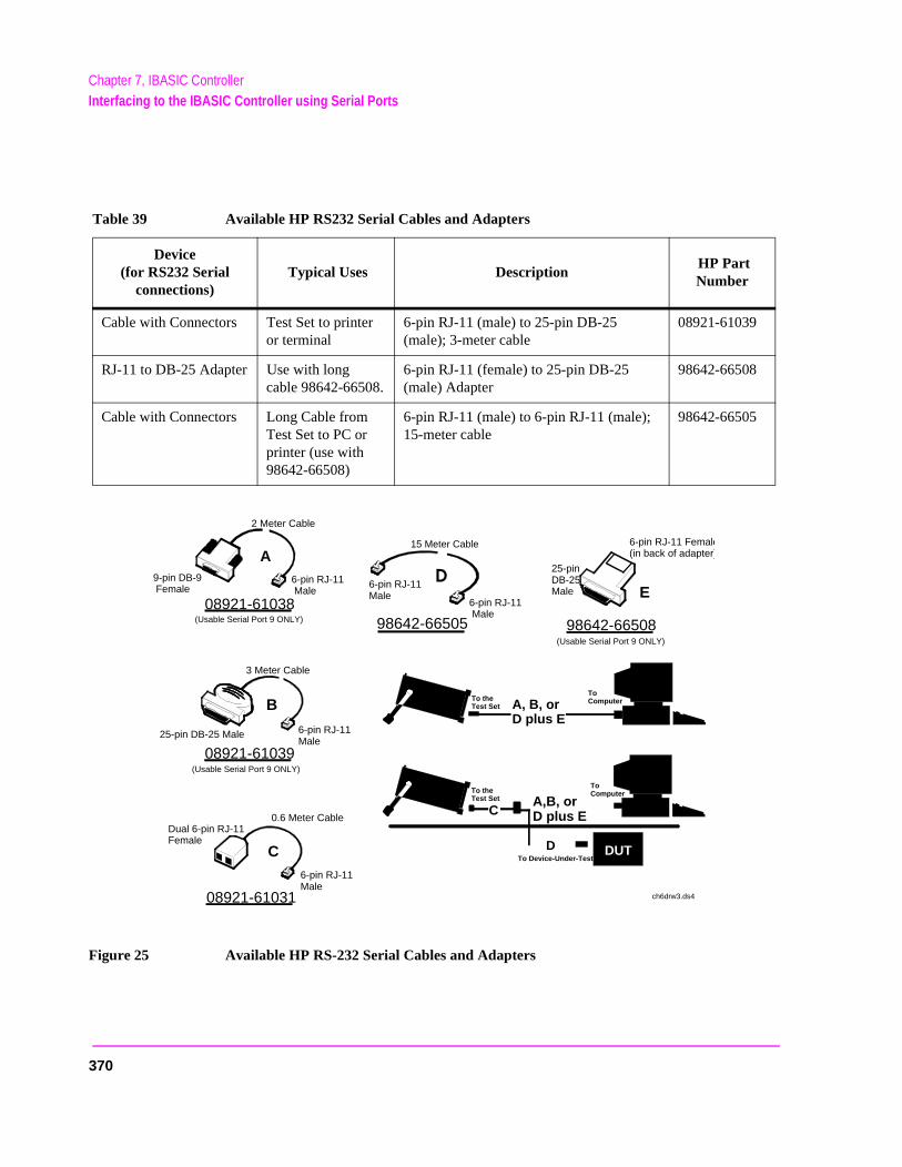
Chapter 7, IBASIC ControllerInterfacing to the IBASIC Controller using Serial Ports
Figure 25 Available HP RS-232 Serial Cables and Adapters
Cable with Connectors Test Set to printer or terminal
6-pin RJ-11 (male) to 25-pin DB-25 (male); 3-meter cable
08921-61039
RJ-11 to DB-25 Adapter Use with long cable 98642-66508.
6-pin RJ-11 (female) to 25-pin DB-25 (male) Adapter
98642-66508
Cable with Connectors Long Cable from Test Set to PC or printer (use with 98642-66508)
6-pin RJ-11 (male) to 6-pin RJ-11 (male); 15-meter cable
98642-66505
Table 39 Available HP RS232 Serial Cables and Adapters
Device (for RS232 Serial
connections) Typical Uses Description
HP Part Number
08921-61038
08921-61039
98642-66508
08921-61031
98642-66505
6-pin RJ-11 Male
9-pin DB-9 Female
6-pin RJ-11 Male
6-pin RJ-11 Male
6-pin RJ-11 Male
6-pin RJ-11 Male
25-pin DB-25 Male
Dual 6-pin RJ-11 Female
6-pin RJ-11 Female(in back of adapter)
25-pin DB-25 Male
3 Meter Cable
15 Meter Cable
0.6 Meter Cable
DUT
To the Test Set
To ComputerTo the
Test Set
To Device-Under-Test
A,B, orD plus E
D
To ComputerA, B, or
D plus E
C
(Usable Serial Port 9 ONLY)
(Usable Serial Port 9 ONLY)
(Usable Serial Port 9 ONLY)
AD
E
C
B
2 Meter Cable
ch6drw3.ds4
370
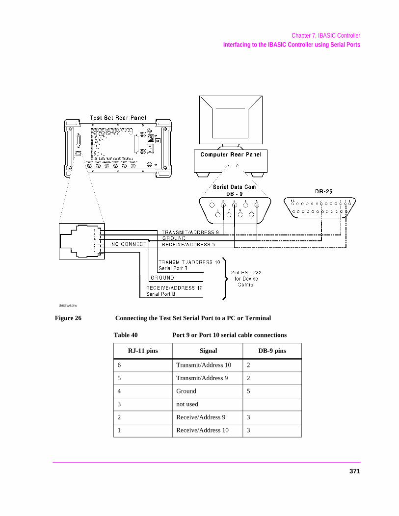
Chapter 7, IBASIC ControllerInterfacing to the IBASIC Controller using Serial Ports
Figure 26 Connecting the Test Set Serial Port to a PC or Terminal
Table 40 Port 9 or Port 10 serial cable connections
RJ-11 pins Signal DB-9 pins
6 Transmit/Address 10 2
5 Transmit/Address 9 2
4 Ground 5
3 not used
2 Receive/Address 9 3
1 Receive/Address 10 3
ch6drw4.drw
371
Chapter 7, IBASIC ControllerInterfacing to the IBASIC Controller using Serial Ports
Code R IS nged
e f the
l be ither
Serial Port 9 Configuration
Table 41 on page 373 and the following paragraphs describe how to configure Serial Port 9 for communications with an external PC or terminal. Implications of the various choices are discussed.
1. Under the To Screen menu, select More, then select IO CONFIG.
2. The I/O CONFIGURE screen will be displayed.
3. Set the Serial Baud Rate, Parity, Data Length, Stop Length, Rcv Pace and Xmt Pace fields to match your PC or terminal settings. The recommended settings are shown in table 41 on page 373. These settings will be retained by the Test Set. They will not change if the PRESET key is pressed, if the Test Set receives a *RST Common Command, or the power is turned on and off.
4. Set the Serial In field to Inst. This routes Serial Port 9 to the IBASIC Command Line field. Characters typed on the external PC or terminal will now appear in the IBASIC Command Line.
5. Set the IBASIC Echo field to ON. This will cause IBASIC character output from commands (such as LIST, PRINT or DISPLAY) or error messages to echo characters to Serial Port 9 (the characters will in turn show up on the external PC or terminal screen). This will allow program listings and syntax error messages to be seen on the external PC or terminal.
6. Another method which can be used to output characters to the external PC or terminal is to execute the IBASIC command, PRINTER IS 9. This causes IBASIC to direct all print output to Select Code 9. Select Code 9 is the Test Set’s Serial Port 9. Select1 is the Test Set’s CRT. Select Code 1 is also the default address for the PRINTEcommand, so all program printer output defaults to the Test Set’s CRT (unless chawith the PRINTER IS command).
7. Set the Inst Echo field to ON. This will cause characters to be echoed back to thexternal PC or terminal as they are received at Serial Port 9. If the echo feature oexternal PC or terminal is also enabled all the characters sent to the Test Set wildisplayed twice on the external PC or terminal. Enable echo on only one device, ethe Test Set or the external PC or terminal.
372
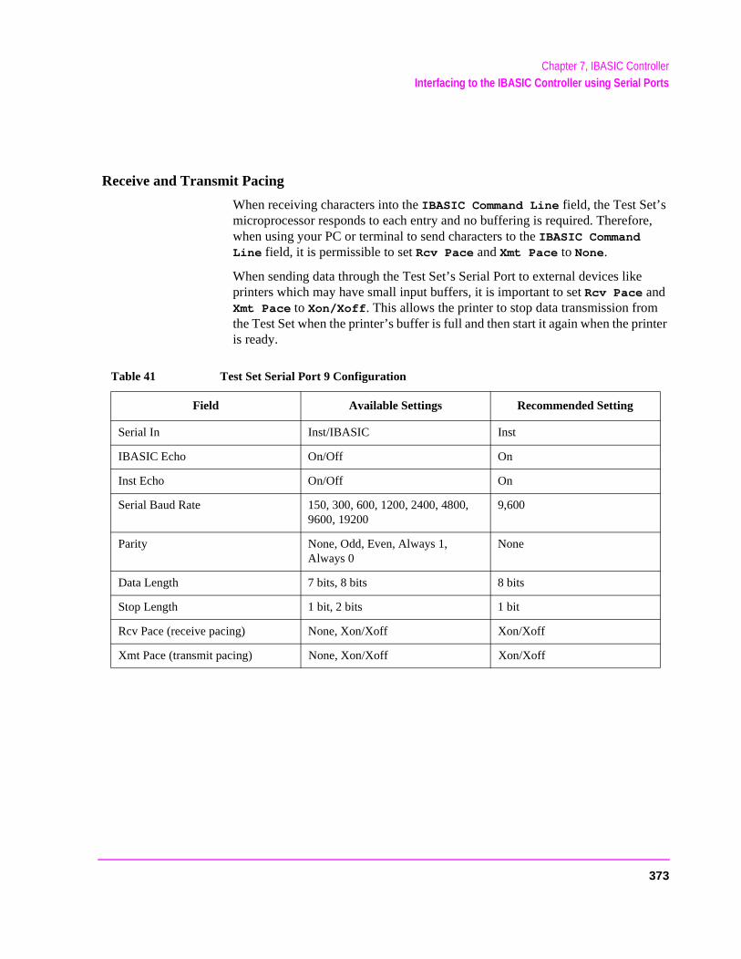
Chapter 7, IBASIC ControllerInterfacing to the IBASIC Controller using Serial Ports
re,
inter
Receive and Transmit Pacing
When receiving characters into the IBASIC Command Line field, the Test Set’s microprocessor responds to each entry and no buffering is required. Therefowhen using your PC or terminal to send characters to the IBASIC Command Line field, it is permissible to set Rcv Pace and Xmt Pace to None.
When sending data through the Test Set’s Serial Port to external devices likeprinters which may have small input buffers, it is important to set Rcv Pace and Xmt Pace to Xon/Xoff. This allows the printer to stop data transmission fromthe Test Set when the printer’s buffer is full and then start it again when the pris ready.
Table 41 Test Set Serial Port 9 Configuration
Field Available Settings Recommended Setting
Serial In Inst/IBASIC Inst
IBASIC Echo On/Off On
Inst Echo On/Off On
Serial Baud Rate 150, 300, 600, 1200, 2400, 4800, 9600, 19200
9,600
Parity None, Odd, Even, Always 1, Always 0
None
Data Length 7 bits, 8 bits 8 bits
Stop Length 1 bit, 2 bits 1 bit
Rcv Pace (receive pacing) None, Xon/Xoff Xon/Xoff
Xmt Pace (transmit pacing) None, Xon/Xoff Xon/Xoff
373
Chapter 7, IBASIC ControllerInterfacing to the IBASIC Controller using Serial Ports
ial rt is
and and
. It the
uter
ed
PC Configuration
To prepare for IBASIC program development, the external PC or terminal must be configured to operate with the Test Set. This configuration includes
• Hardware • Terminal Emulator Software
PC Serial Port Configuration
Refer to figure 26 on page 371 for connection details. Connect the Test Set’s SerPort 9 to a serial I/O (input/output) port on the PC. On many PCs, a serial poavailable as either a 25-pin DB-25 (female) connector or a 9-pin DB-9 (male)connector. This port can be configured as COM1, COM2, COM3, or COM4 (communications port 1, 2, 3, or 4) depending on the installed PC hardware user-defined setup. Refer to the instructions shipped with the PC for hardwaresoftware configuration information.
Terminal Emulator Configuration Information
A “terminal emulator” is an application program running on the PC that communicates with one of the serial communication ports installed in the PCprovides a bi-directional means of sending and receiving ASCII characters toTest Set’s serial port.
In general, a “terminal emulator” enables the PC to act like a dedicated compterminal. This type of terminal was used before PCs to allow remote users tocommunicate through RS232 with central mainframe computers. An ANSI-compatible terminal like the Digital Equipment Corporation VT-100 can be usto directly communicate with the Test Set. PC terminal emulation applicationprograms have been designed to have setup fields much like these older technology terminals.
374
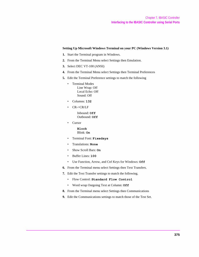
Chapter 7, IBASIC ControllerInterfacing to the IBASIC Controller using Serial Ports
Setting Up Microsoft Windows Terminal on your PC (Windows Version 3.1)
1. Start the Terminal program in Windows.
2. From the Terminal Menu select Settings then Emulation.
3. Select DEC VT-100 (ANSI)
4. From the Terminal Menu select Settings then Terminal Preferences
5. Edit the Terminal Preference settings to match the following
• Terminal Modes Line Wrap: Off Local Echo: Off Sound: Off
• Columns: 132
• CR->CR/LF
Inbound: Off Outbound: Off
• Cursor
Block Blink: On
• Terminal Font: Fixedsys
• Translations: None
• Show Scroll Bars: On
• Buffer Lines: 100
• Use Function, Arrow, and Ctrl Keys for Windows: Off
6. From the Terminal menu select Settings then Text Transfers.
7. Edit the Text Transfer settings to match the following.
• Flow Control: Standard Flow Control
• Word wrap Outgoing Text at Column: Off
8. From the Terminal menu select Settings then Communications
9. Edit the Communications settings to match those of the Test Set.
375

Chapter 7, IBASIC ControllerInterfacing to the IBASIC Controller using Serial Ports
Example Terminal Communications Settings
• Baud Rate: 9600
• Data Bits: 8
• Stop Bits: 1
• Parity: None
• Flow Control: Xon/Xoff
• Connector: Com1 (be sure to match your current setup)
• Parity Check: Off
• Carrier Detect: Off
376
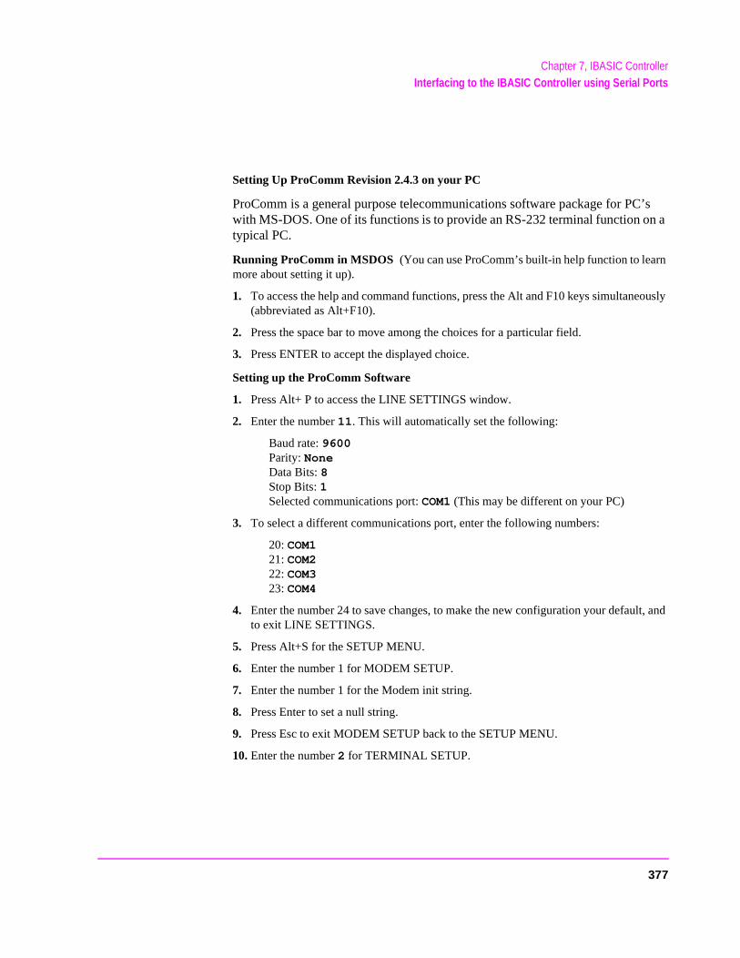
Chapter 7, IBASIC ControllerInterfacing to the IBASIC Controller using Serial Ports
’s n a
n
ously
t, and
Setting Up ProComm Revision 2.4.3 on your PC
ProComm is a general purpose telecommunications software package for PCwith MS-DOS. One of its functions is to provide an RS-232 terminal function otypical PC.
Running ProComm in MSDOS (You can use ProComm’s built-in help function to learmore about setting it up).
1. To access the help and command functions, press the Alt and F10 keys simultane(abbreviated as Alt+F10).
2. Press the space bar to move among the choices for a particular field.
3. Press ENTER to accept the displayed choice.
Setting up the ProComm Software
1. Press Alt+ P to access the LINE SETTINGS window.
2. Enter the number 11. This will automatically set the following:
Baud rate: 9600 Parity: None Data Bits: 8 Stop Bits: 1 Selected communications port: COM1 (This may be different on your PC)
3. To select a different communications port, enter the following numbers:
20: COM1 21: COM2 22: COM3 23: COM4
4. Enter the number 24 to save changes, to make the new configuration your defaulto exit LINE SETTINGS.
5. Press Alt+S for the SETUP MENU.
6. Enter the number 1 for MODEM SETUP.
7. Enter the number 1 for the Modem init string.
8. Press Enter to set a null string.
9. Press Esc to exit MODEM SETUP back to the SETUP MENU.
10. Enter the number 2 for TERMINAL SETUP.
377
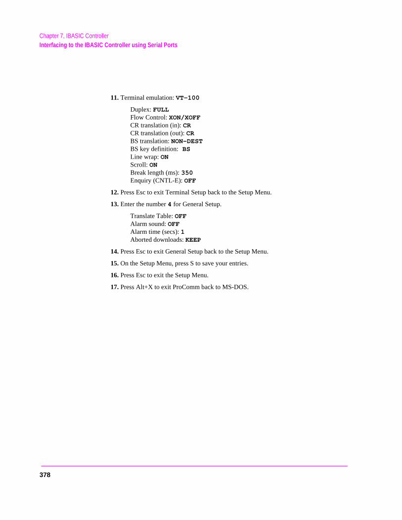
Chapter 7, IBASIC ControllerInterfacing to the IBASIC Controller using Serial Ports
11. Terminal emulation: VT-100
Duplex: FULL Flow Control: XON/XOFF CR translation (in): CR CR translation (out): CR BS translation: NON-DEST BS key definition: BS Line wrap: ON Scroll: ON Break length (ms): 350 Enquiry (CNTL-E): OFF
12. Press Esc to exit Terminal Setup back to the Setup Menu.
13. Enter the number 4 for General Setup.
Translate Table: OFF Alarm sound: OFF Alarm time (secs): 1 Aborted downloads: KEEP
14. Press Esc to exit General Setup back to the Setup Menu.
15. On the Setup Menu, press S to save your entries.
16. Press Esc to exit the Setup Menu.
17. Press Alt+X to exit ProComm back to MS-DOS.
378
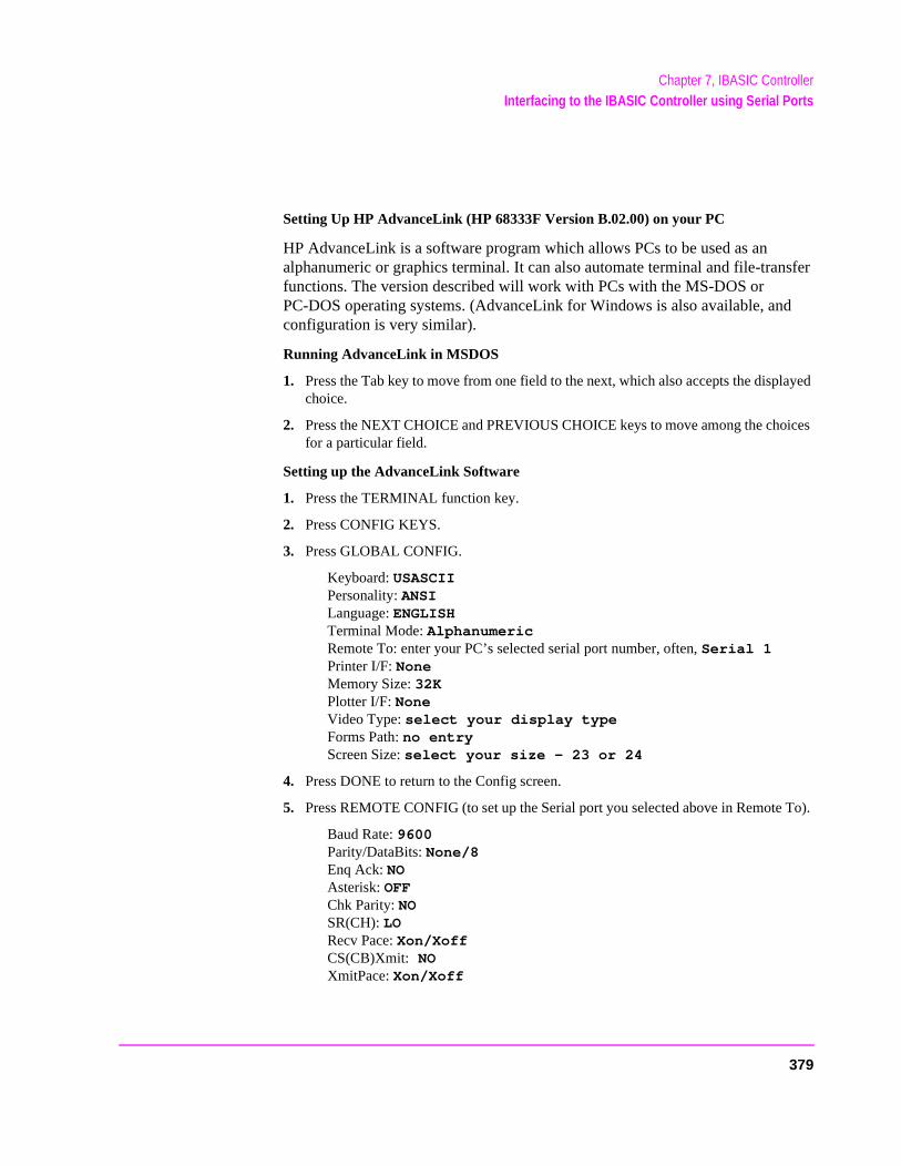
Chapter 7, IBASIC ControllerInterfacing to the IBASIC Controller using Serial Ports
Setting Up HP AdvanceLink (HP 68333F Version B.02.00) on your PC
HP AdvanceLink is a software program which allows PCs to be used as an alphanumeric or graphics terminal. It can also automate terminal and file-transfer functions. The version described will work with PCs with the MS-DOS or PC-DOS operating systems. (AdvanceLink for Windows is also available, and configuration is very similar).
Running AdvanceLink in MSDOS
1. Press the Tab key to move from one field to the next, which also accepts the displayed choice.
2. Press the NEXT CHOICE and PREVIOUS CHOICE keys to move among the choices for a particular field.
Setting up the AdvanceLink Software
1. Press the TERMINAL function key.
2. Press CONFIG KEYS.
3. Press GLOBAL CONFIG.
Keyboard: USASCII Personality: ANSI Language: ENGLISH Terminal Mode: Alphanumeric Remote To: enter your PC’s selected serial port number, often, Serial 1 Printer I/F: None Memory Size: 32K Plotter I/F: None Video Type: select your display type Forms Path: no entry Screen Size: select your size — 23 or 24
4. Press DONE to return to the Config screen.
5. Press REMOTE CONFIG (to set up the Serial port you selected above in Remote To).
Baud Rate: 9600 Parity/DataBits: None/8 Enq Ack: NO Asterisk: OFF Chk Parity: NO SR(CH): LO Recv Pace: Xon/Xoff CS(CB)Xmit: NO XmitPace: Xon/Xoff
379
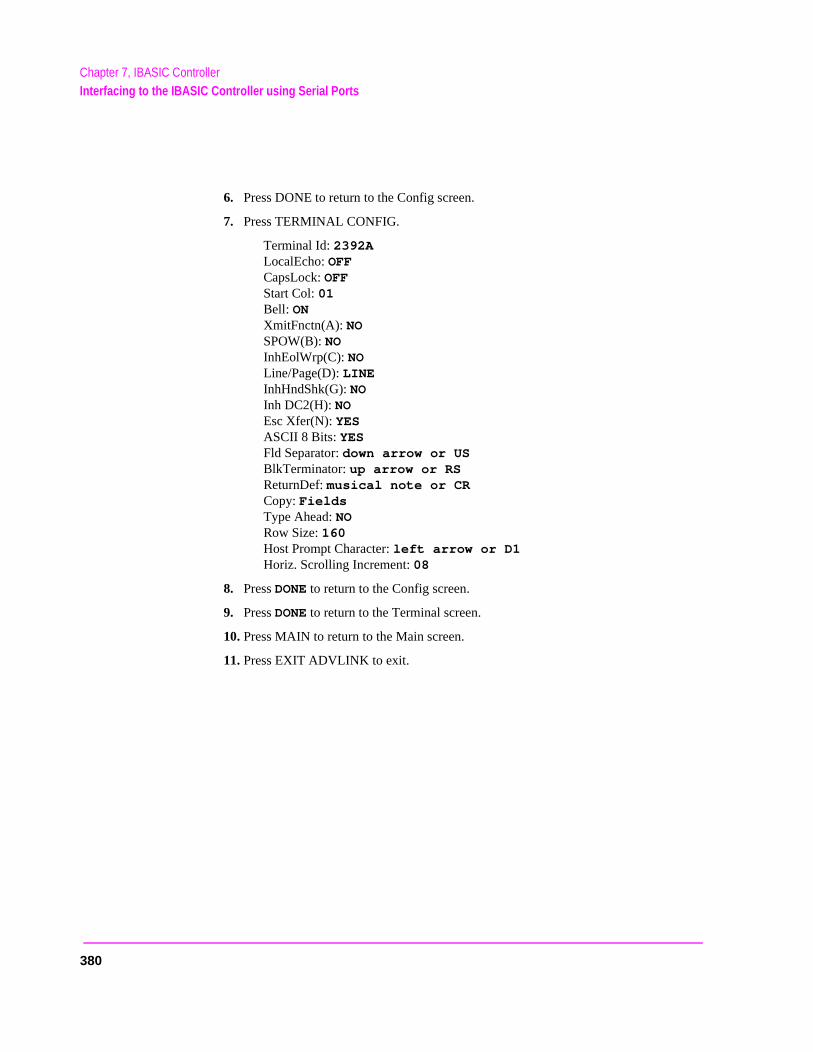
Chapter 7, IBASIC ControllerInterfacing to the IBASIC Controller using Serial Ports
6. Press DONE to return to the Config screen.
7. Press TERMINAL CONFIG.
Terminal Id: 2392A LocalEcho: OFF CapsLock: OFF Start Col: 01 Bell: ON XmitFnctn(A): NO SPOW(B): NO InhEolWrp(C): NO Line/Page(D): LINE InhHndShk(G): NO Inh DC2(H): NO Esc Xfer(N): YES ASCII 8 Bits: YES Fld Separator: down arrow or US BlkTerminator: up arrow or RS ReturnDef: musical note or CR Copy: Fields Type Ahead: NO Row Size: 160 Host Prompt Character: left arrow or D1 Horiz. Scrolling Increment: 08
8. Press DONE to return to the Config screen.
9. Press DONE to return to the Terminal screen.
10. Press MAIN to return to the Main screen.
11. Press EXIT ADVLINK to exit.
380

Chapter 7, IBASIC ControllerInterfacing to the IBASIC Controller using Serial Ports
Terminal Configuration
Use the cable information in table 39 on page 369 and figure 25 on page 370 for connecting to an external terminal. Terminals typically have a DB-25 (male) connector. Set the terminal for DEC VT-100 ANSI emulation. Many ASCII terminals will also function properly.
To set up the terminal, use the field settings found in the HP AdvanceLink terminal emulator section found earlier in this chapter. As a minimum, make sure the terminal’s basic setup information matches the fields on the Test Set’s I/OCONFIGURE screen (refer to table 41 on page 373 for recommended settings).
381
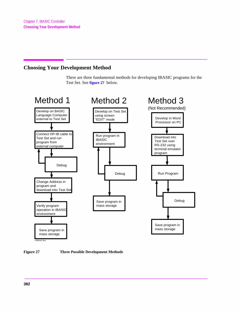
Chapter 7, IBASIC ControllerChoosing Your Development Method
Choosing Your Development Method
There are three fundamental methods for developing IBASIC programs for the Test Set. See figure 27 below.
Figure 27 Three Possible Development Methods
Develop on Test Setusing screen"EDIT" mode
Run program inIBASIC environment
Develop in Word Processor on PC
Download into Test Set over RS-232 using terminal emulator program
Develop on BASIC Language Computer external to Test Set
Connect HP-IB cable to Test Set and run program from external computer
Debug Run Program
Debug
Debug
Save program in mass storage
Method 1 Method 2 Method 3(Not Recommended)
Change Address in program anddownload into Test Set
Verify program operation in IBASIC environment
Save program in mass storage
Save program in mass storage
ch6drw2.drw
382
Chapter 7, IBASIC ControllerChoosing Your Development Method
easily
to the ays n
ger
with is
he t and ing
after l
ger
Method 1
Using a BASIC language computer (either an HP technical computer or a PC running BASIC with HP-IB) is the best method for developing any size program. This is because the program can be debugged directly on the external computer before downloading the program into the Test Set. Using this approach the programmer can observe the Test Set’s display to see changes in state and verify the correct measurements.
Method 2
If a BASIC language computer is not available, program development can bedone directly on the Test Set using the IBASIC EDIT mode. A PC connectedthe Test Set through RS-232, as described earlier in this chapter, is used as CRT and keyboard for the internal controller. In this method, the program alwresides in the Test Set and can be run at any time. Mass storage is usually aSRAM card. When running IBASIC programs on the Test Set’s internal controller, the Test Set displays only the IBASIC screen, not the individual instrument screens as the program executes. This makes troubleshooting larprograms more difficult.
Method 3
The third method of program development is to use a word processor on a PCRS-232, and then download the program into the Test Set for execution. Thisthe least favorable choice for development because downloading code into tTest Set over RS-232 requires a loader utility program running in the Test Sea RAM memory card present as an intermediate storage location before runnthe program. (For shorter programs, the intermediate storage location is not necessary.) No IBASIC command syntax is checked until the program is run downloading. Also, when running IBASIC programs on the Test Set’s internacontroller, the Test Set displays only the IBASIC screen, not the individual instrument screens as the program executes. This makes troubleshooting larprograms more difficult.
383
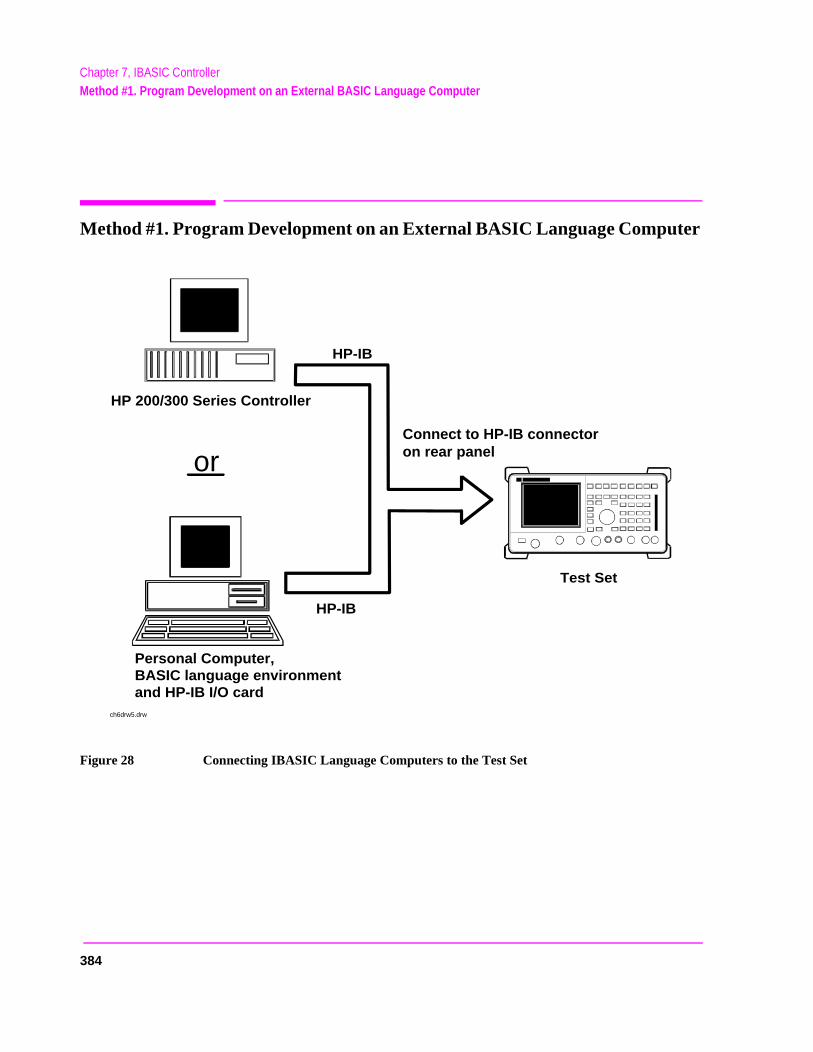
Chapter 7, IBASIC ControllerMethod #1. Program Development on an External BASIC Language Computer
Method #1. Program Development on an External BASIC Language Computer
Figure 28 Connecting IBASIC Language Computers to the Test Set
HP-IB
HP 200/300 Series Controller
Test Set
Personal Computer,BASIC language environmentand HP-IB I/O card
HP-IB
Connect to HP-IB connector on rear panelor
ch6drw5.drw
384
Chapter 7, IBASIC ControllerMethod #1. Program Development on an External BASIC Language Computer
nal
e is
2 or
200/
P-
Configuring the Test Set’s HP-IB Interface
To use HP-IB (the IEEE 488 interface bus) as a means of communicating with the Test Set, connect a standard HP-IB cable (such as the HP 10833B) between the Test Set’s rear-panel HP-IB connector and the HP-IB connector on the exterBASIC language computer.
On the Test Set 1. Select the I/O CONFIGURE screen.
2. Set the Mode field to Talk&Lstn.
NOTE: If the Mode field is set to Control, there could possibly be a System Controller conflictbetween the external BASIC language computer and the Test Set, resulting in either anInterface Status Error or “lock up” of the HP-IB. Refer to "Passing Control" on page 318.
3. Set the HP-IB Adrs field to the desired address for the Test Set. The default valu14.
Compatible BASIC Language Computers
As shown in figure 28 on page 384, there are two types of computers that can be used in this development method.
• The HP 9000 Series 200/300 Workstation running HP Rocky Mountain BASIC 6.later. IBASIC is a subset of HP Rocky Mountain BASIC (RMB). All IBASIC commands are compatible with RMB and thus will execute from a HP 9000 Series300 Workstation.
• A PC, running Windows 3.1 or Windows NT, with HP BASIC for Windows and an HIB interface card can be used.
385
Chapter 7, IBASIC ControllerMethod #1. Program Development on an External BASIC Language Computer
T)test
s in-
gram.
end
HP BASIC for Windows PC Configuration for Windows NT Operating System
To prepare for HP BASIC program development utilizing Windows NT, the external PC must be configured to operate with the Test Set.
You will need:
• an HP 82341B/C interface card (the HP 82335 card does not support Windows N• a licensed version with security key of HP BASIC for Windows. You can get the la
files from ftp://hpislsup.lvld.hp.com/pub/pc/index.html. Select the HP BASIC for windows archives and follow the instructions for download.
How to install:
1. Install the HP 82341B/C into an open expansion slot. Refer to the interface card’stallation guide details. Utilize the default card settings.
2. Install the SICL libraries using the SETUP32.EXE setup file.3. Run the SICL I_O Config program to configure the card. 4. Select HP 82340/82341 HP-IB from the available interface list of choices. 5. Select the Configure command button. Use the default settings shown by the pro
This will verify that the card is functioning. 6. Install HP BASIC for Windows 6.3 or later.7. Run HP BASIC for Windows.8. Edit the AUTOST file, change line 330 as follows:
LOAD BIN "HPIBS;DEV hpib7" !SICL Library for HP 82341 card
9. Re-store the AUTOST file10. Quit HP BASIC for Windows11. Run HP BASIC for Windows. The program should load normally and allow you to s
orders to the Test Set.
386
Chapter 7, IBASIC ControllerMethod #1. Program Development on an External BASIC Language Computer
ss of
et’s . If
is 7 mand e ured lly
it.
Program Development Procedure
As discussed in "Overview of the Test Set" in chapter 1, the Test Set has two HP-IB buses, an internal HP-IB at select code 8 and an external HP-IB at select code 7. The Test Set’s built-in IBASIC controller uses the internal HP-IB to communicate with the Test Set’s various instruments and devices. The procedeveloping a program on an external BASIC language computer utilizes thishardware feature to an advantage. First, develop the program directly on theexternal BASIC language computer treating the Test Set as a device on the external BASIC language computer’s HP-IB. For example, to setup the Test SRF Generator use the OUTPUT command with the Test Set’s HP-IB addressthe select code of the HP-IB card in the external BASIC language computer and the address of the Test Set is 14 the address following the OUTPUT comwould be 714. When the command executes on the external BASIC languagcomputer the information on how the Test Set’s RF Generator is to be configis sent to the Test Set through its external HP-IB bus. After the program is fudeveloped, making it run on the Test Set is simply a matter of changing the address of all the HP-IB commands to 8XX (Test Set internal HP-IB bus) anddownloading the program into the Test Set’s IBASIC controller and executing
387

Chapter 7, IBASIC ControllerMethod #1. Program Development on an External BASIC Language Computer
There are two ways of allowing easy conversion of all HP-IB commands to a different address. The first way is to establish a variable to which the 3-digit address number is assigned.
For example
10 Addr = 714 ! Sets the value of variable Addr to be 714.20 OUTPUT Addr;"*RST"!Commands the Test Set to reset at address 714.
To change the address, simply change the value of variable Addr to 814.
For example
10 Addr = 814 ! Sets the value of variable Addr to be 814.20 OUTPUT Addr;"*RST"! Commands the Test Set to reset at address 814.
A second method is to assign an I/O path to the desired I/O port.
For example
To control device #14 on the port with select code 7.
20 ! Establishes IO path to select code 7 address 1410 ASSIGN @Device TO 71430 ! Commands Test Set to reset at address 714.20 OUTPUT @Device;"*RST"
To change the address, simply change line 10 to
10 ASSIGN @Device TO 800.
NOTE: The dedicated HP-IB interface at select code 8 conforms to the IEEE 488.2 Standard in allrespects but one. The difference being that each instrument on the bus does not have aunique address. The Instrument Control Hardware determines which instrument is beingaddressed with the command syntax. As such an explicit device address does not have tobe specified. The address 800 and 814 are equally correct.
388
Chapter 7, IBASIC ControllerMethod #1. Program Development on an External BASIC Language Computer
t an be r. to
Downloading Programs to the Test Set through HP-IB
An IBASIC PROGram subsystem has been developed to allow the external BASIC language controller to download programs to the Test Set through HP-IB (refer to the "PROGram Subsystem Commands" on page 411 for more information on the PROGram Subsystem). Four commands from the external BASIC language controller to the Test Set are necessary to transfer the program. The commands are executed serially allowing enough time for each command to finish executing. (The Test Set’s HP-IB Mode field must be set to Talk&Lstn, and the TESTS (IBASIC CONTROLLER) screen must be displayed).
1. OUTPUT 714;"PROG:DEL:ALL"
Deletes any programs that reside in Test Set RAM.
2. OUTPUT 714;"PROG:DEF #0"
Defines the address in Test Set RAM where the downloaded program will be stored.
3. LIST #714
Causes all program lines to transfer over HP-IB to the Test Set which is at address 714.
4. OUTPUT 714;" "END
Defines end of download process by generating an EOI command.
After the above commands complete the program code will be in the Test Seready to run. If any bugs are detected when the program is run, the program cuploaded back into the external BASIC language controller to correct the erroAlternately the full screen IBASIC EDIT function through RS-232 can be usedcorrect the error (refer to "Method #2. Developing Programs on the Test Set Using the IBASIC EDIT Mode" on page 392 for details).
After the program is working properly in the Test Set IBASIC environment, it should be stored for backup purposes.
389

Chapter 7, IBASIC ControllerMethod #1. Program Development on an External BASIC Language Computer
Uploading Programs from the Test Set to an External BASIC Controller through HP-IB
To upload a program from the Test Set to an external BASIC language controller through HP-IB the following program, which uses a command from the PROGram subsystem to initiate the upload, must be running on the external BASIC language controller. The uploaded program is stored to a file specified by the user.
In the following program the external BASIC language controller is a PC running TransEra HT BASIC. The file is stored to the C:\HTB386 directory. If the external BASIC language controller is an HP 9000 Series 200/300 Workstation, modify the mass storage volume specifier appropriately. After running the program, the uploaded program code will be in the designated file. Use the GET command to retrieve the file for editing.
390
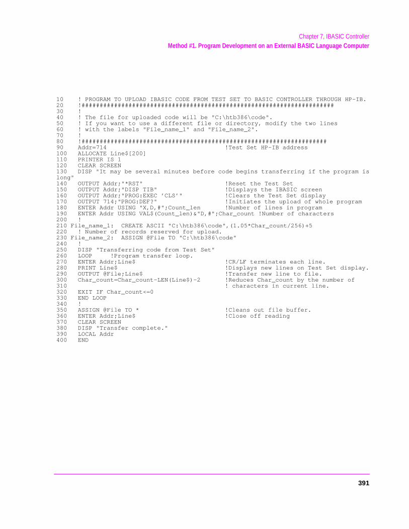
Chapter 7, IBASIC ControllerMethod #1. Program Development on an External BASIC Language Computer
10 ! PROGRAM TO UPLOAD IBASIC CODE FROM TEST SET TO BASIC CONTROLLER THROUGH HP-IB.20 !######################################################################30 !40 ! The file for uploaded code will be "C:\htb386\code".50 ! If you want to use a different file or directory, modify the two lines60 ! with the labels "File_name_1" and "File_name_2".70 !80 !####################################################################90 Addr=714 !Test Set HP-IB address100 ALLOCATE Line$[200]110 PRINTER IS 1120 CLEAR SCREEN130 DISP "It may be several minutes before code begins transferring if the program islong"140 OUTPUT Addr;"*RST" !Reset the Test Set150 OUTPUT Addr;"DISP TIB" !Displays the IBASIC screen160 OUTPUT Addr;"PROG:EXEC ’CLS’" !Clears the Test Set display170 OUTPUT 714;"PROG:DEF?" !Initiates the upload of whole program180 ENTER Addr USING "X,D,#";Count_len !Number of lines in program190 ENTER Addr USING VAL$(Count_len)&"D,#";Char_count !Number of characters200 !210 File_name_1: CREATE ASCII "C:\htb386\code",(1.05*Char_count/256)+5220 ! Number of records reserved for upload.230 File_name_2: ASSIGN @File TO "C:\htb386\code"240 !250 DISP "Transferring code from Test Set"260 LOOP !Program transfer loop.270 ENTER Addr;Line$ !CR/LF terminates each line.280 PRINT Line$ !Displays new lines on Test Set display.290 OUTPUT @File;Line$ !Transfer new line to file.300 Char_count=Char_count-LEN(Line$)-2 !Reduces Char_count by the number of310 ! characters in current line.320 EXIT IF Char_count<=0330 END LOOP340 !350 ASSIGN @File TO * !Cleans out file buffer.360 ENTER Addr;Line$ !Close off reading370 CLEAR SCREEN380 DISP "Transfer complete."390 LOCAL Addr400 END
391
Chapter 7, IBASIC ControllerMethod #2. Developing Programs on the Test Set Using the IBASIC EDIT Mode
des
nal al or r de
Method #2. Developing Programs on the Test Set Using the IBASIC EDIT Mode
If a BASIC language computer is not available, program development can be done directly on the Test Set using the IBASIC EDIT mode. A terminal or PC connected to the Test Set through RS-232 is used as the CRT and keyboard for the Test Set’s built-in IBASIC controller. In this method, the program always resiin the Test Set and can be run at any time. Mass storage is usually an SRAMmemory card. When running IBASIC programs on the Test Set’s internal controller, the Test Set displays only the IBASIC screen.
The Test Set’s IBASIC controller has an editor that is interactive with a termior PC over the RS-232 serial port. (The editor does not work unless a terminPC with terminal emulator is connected to Serial Port 9.) The editor, hereaftereferred to as the “IBASIC EDIT Mode”, allows the programmer to develop codirectly in the Test Set with no uploading or downloading. The IBASIC EDIT Mode can be used to develop programs from scratch or to modify existing programs. Refer to "Interfacing to the IBASIC Controller using Serial Ports" on page 368 for information on connecting a terminal or PC to the Test Set.
392

Chapter 7, IBASIC ControllerMethod #2. Developing Programs on the Test Set Using the IBASIC EDIT Mode
t
Selecting the IBASIC Command Line Field
To use the IBASIC EDIT Mode for program development, the IBASIC Command Line field must be displayed on the Test Set and Serial Port 9 must be connected to the IBASIC Command Line field. An IBASIC command, sent as a series of ASCII characters through Serial Port 9, will appear on the IBASIC Command Line field. When a carriage return/line feed is encountered, the Test Set will attempt to execute the command. To display the IBASIC Command Line field on the Test Set execute the following steps:
1. Press the TESTS key.
2. The TESTS (Main Menu) screen will be displayed.
3. Using the rotary knob, position the cursor on the IBASIC Cntrl field and select it.
4. The TESTS (IBASIC CONTROLLER) screen will be displayed.
5. The small horizontal rectangle at the top-left is the IBASIC Command Line .
To Access the IBASIC Command Line Field
1. Position the cursor on the screen’s upper left. This is the IBASIC Command Line field.
2. The IBASIC Command Line field does not have a title like other fields in the TesSet; it is the highlighted, horizontal 2-line “bar” just below the screen title, TESTS(IBASIC Controller).
To Use the IBASIC Command Line Field with the Test Set’s Rotary Knob
1. Position the cursor at the IBASIC Command Line field and push the knob.
2. A Choices: field will be displayed in the lower, right corner of the display.
3. By rotating the knob, a list of ASCII characters and cursor positioning commands can be displayed on the right side of the screen.
4. When the cursor is next to the desired character or command, push the knob to select that character.
5. No external hardware is required for this entry method, but it is tedious and is recommended only for short commands. Use this method when doing simple tasks such as initializing memory cards or CATaloging a memory card.
6. Program development using the rotary knob alone is not recommended.
393
Chapter 7, IBASIC ControllerMethod #2. Developing Programs on the Test Set Using the IBASIC EDIT Mode
on
IC
or et.
se rminals n Test ntly. EDIT
here e
Entering and Exiting the IBASIC EDIT Mode
To enter the IBASIC EDIT Mode first position the cursor on the IBASIC Command Line field, type the word EDIT on the terminal or PC connected to the Test Set and then press the ENTER key on the terminal or PC. At this point the Test Set will fill the PC screen with 22 lines of IBASIC code from the program currently in the Test Set’s RAM memory. No program lines will be displayed the Test Set screen. If no program is currently in the Test Set’s memory, the number 10 will be displayed on the terminal or PC screen. This represents program line number 10 and is displayed to allow you to begin writing an IBASprogram beginning at line number 10. The “*” annunciator will be displayed inthe upper, right corner of the Test Set indicating that the IBASIC controller isrunning to support the full screen edit mode.
After editing is complete, exit the IBASIC EDIT Mode by pressing the terminalPC’s ESCAPE key twice or pressing the SHIFT CANCEL keys on the Test S
A variety of editing commands are supported by the IBASIC EDIT Mode. Thecommands are activated in the Test Set as escape code sequences. Most teand PC terminal emulator programs allow function keys to be configured withuser defined escape code sequences and user defined labels for the keys. Aescape command (when received by a peripheral device like a printer or the Set) causes the peripheral to recognize subsequent ASCII characters differeIn the case of the Test Set, escape sequences are used for executing IBASICMode editing commands.
For example, ESCAPE [L causes the Test Set to insert a new line number wthe cursor is positioned. Table 42 on page 396 lists the editing escape codes for thTest Set. There is no escape code for DELETE CHARACTER. Use the Backspace key for deleting. Use the arrow keys to position the cursor.
394
Chapter 7, IBASIC ControllerMethod #2. Developing Programs on the Test Set Using the IBASIC EDIT Mode
soft you
tivate
Setting Up Function Keys In Microsoft Windows Terminal
When in the TERMINAL mode, click on Settings, then Function Keys. ^[ is ESCAPE in Windows Terminal. See table 42 on page 396 for the escape codes.
NOTE: Windows Terminal seems to work best when a mouse is used to access the function keys, notthe keyboard. Also, scrolling a program works best when the Terminal window display ismaximized).
Setting Up Function Keys in HP AdvanceLink
• From the Main (highest level) screen, set up the 8 softkeys as follows:
1. Display User Definition screens by pressing Ctrl F9.
2. Enter all the LABEL titles for K1 through K8.
3. Activate the “Display Function” feature by pressing softkey F7.
4. Now you can enter the escape codes for each edit command aligned with thekey definitions you just entered. With the Display Functions key pressed, whenpress the escape key, a left arrow will be displayed.
• Once you have set up all 8 keys, you activate them by pressing Shift F12. To deacyour user defined softkeys, press F12.
• (- is ESCAPE in HP AdvanceLink. See table 42 on page 396 for the escape codes.
395
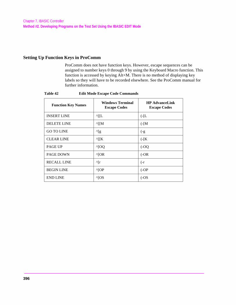
Chapter 7, IBASIC ControllerMethod #2. Developing Programs on the Test Set Using the IBASIC EDIT Mode
Setting Up Function Keys in ProComm
ProComm does not have function keys. However, escape sequences can be assigned to number keys 0 through 9 by using the Keyboard Macro function. This function is accessed by keying Alt+M. There is no method of displaying key labels so they will have to be recorded elsewhere. See the ProComm manual for further information.
Table 42 Edit Mode Escape Code Commands
Function Key Names Windows Terminal
Escape Codes HP AdvanceLink
Escape Codes
INSERT LINE ^[[L (-[L
DELETE LINE ^[[M (-[M
GO TO LINE ^[g (-g
CLEAR LINE ^[[K (-[K
PAGE UP ^[OQ (-OQ
PAGE DOWN ^[OR (-OR
RECALL LINE ^[r (-r
BEGIN LINE ^[OP (-OP
END LINE ^[OS (-OS
396
Chapter 7, IBASIC ControllerMethod #3. Developing Programs Using Word Processor on a PC (Least Preferred)
Method #3. Developing Programs Using Word Processor on a PC (Least Preferred)
The third method of IBASIC program development is to write the program using a word processor on a PC, save it as an ASCII file, and then download it into the Test Set through the serial port. The benefit of this method is that it can be done on the PC without connecting to a Test Set until download and no BASIC language compiler/interpreter is needed. The primary drawback is that no syntax checking occurs until the downloaded program is run on the Test Set. A second drawback is that, especially for longer programs (>100 lines), it is very time-consuming to transfer the code into the Test Set.
Configuring a Word Processor
The word processor on which the IBASIC code is developed must be able to save the file in ASCII format and have an ASCII file transfer utility. This is necessary because word processors use a variety of escape codes to mark all the special display formats such as bold face, font size, indented text, and the like. When a word processor file is stored in ASCII format, all escape codes are stripped off. The ASCII file transfer utility is used to transfer the file to the Test Set.
NOTE: The GET command can be used on external BASIC language controllers to load ASCII filescontaining IBASIC programs developed on word processors. Once loaded, the steps fordownloading described in "Method #1. Program Development on an External BASICLanguage Computer" on page 384 can be used to transfer the program to the Test Set.
397
Chapter 7, IBASIC ControllerMethod #3. Developing Programs Using Word Processor on a PC (Least Preferred)
Writing Lines of IBASIC Code on a Word Processor
When writing IBASIC programs, follow these steps to ensure that the Test Set will accept the code when it is downloaded.
1. Always begin new lines at the far left margin. Never use a leading space or tab. 2. Number each consecutive line just like an IBASIC language program. 3. Typically begin with 10 and increment by ten for each consecutive line. 4. Do not leave any space or double space between lines. 5. Make sure to use hard carriage return / line feeds at the end of each line. 6. When saving the completed program, save it as an ASCII file. Some word processors
have ASCII options which require that the user specify CR/LF at the end of each line. It is important that each line end with a carriage return / line feed.
7. Experiment with a short program first to make sure everything is working correctly.
398
Chapter 7, IBASIC ControllerMethod #3. Developing Programs Using Word Processor on a PC (Least Preferred)
sing
Transferring Programs from the Word Processor to the Test Set
For short (less than 100 lines) programs, use an ASCII file transfer utility on the PC to send the program, one line at a time, down to the Test Set over RS-232 directly into the IBASIC Command Line field. The Test Set must be configured to receive serial ASCII characters by positioning the Test Set cursor at the IBASIC Command Line field as explained under "Method #2. Developing Programs on the Test Set Using the IBASIC EDIT Mode" on page 392. With this setup, when ASCII characters are received they are sent to the IBASIC Command Line field. When a carriage return / line feed is received, the Test Set will parse the line into the IBASIC program memory. Each line takes about two seconds to scroll in and be parsed. This becomes very time consuming for long programs. An alternative for longer programs is discussed later in this section.
To start the transfer process make sure there is no program in the Test Set’sIBASIC RAM memory by executing a SCRATCH command from the IBASICCommand Line.
The following example shows how to transfer a short program (<100 lines) uMicrosoft Windows Terminal.
1. Make sure the Test Set cursor is in the upper left of the IBASIC Command Line field. 2. Select the Terminal application in the Accessories Group. Set it up as de-
scribed in earlier in this chapter. 3. Select the following:
SettingsText TransfersFlow Control: Line at a TimeDelay Between Lines: 25/10 SecWord WrapOutgoing Text at Column: Off.
4. Select the following:TransfersSend Text FileFollowing CR:
Strip LF selectedAppend LF not selected.
5. Select the text file to be transferred and begin the transfer by selecting (OK).
399
Chapter 7, IBASIC ControllerMethod #3. Developing Programs Using Word Processor on a PC (Least Preferred)
r t Set r n
lines ning.
e
o gram
, m
rd. 650
ng an DN
le
As the transfer starts the IBASIC Command Line field will intensify and characters will scroll in left to right. As each line is finished the “*” annunciatowill be displayed, for about 0.5 seconds, in the upper, right corner of the Tesindicating that the IBASIC controller is running as the line is parsed. If anotheline is sent before this parsing is complete, the Test Set will beep indicating aerror, and the next line of the transfer will be rejected.
If the transfer is rejected, the transfer must be halted and the delay between increased to a slightly higher number. Start the transfer again from the beginWhen all lines have transferred, list the program to verify it was completely received. At this time, the program is ready to run. The RUN command can bkeyed in from the PC or the K1 Run key in the TESTS (IBASIC Controller) screen can be pressed.
NOTE: Do not press the Run Test key in the TESTS (Main Menu) screen as this will scratch theprogram you just loaded and look to the memory card for a procedure file.
For longer programs (greater than 100 lines), transferring the ASCII text file directly into the IBASIC program memory through the RS-232 serial port is totime consuming. To speed the process up, it is necessary to transfer the prousing a two step process.
1. Transfer the ASCII text file directly to a Test Set mass storage location (typically an SRAM card).
2. Perform a GET command to bring the program from mass storage into the IBASIC pro-gram memory.
To perform the ASCII text file transfer for long programs, an IBASIC programrunning in the Test Set, is required to manage the transfer. A suitable progratitled “ASCII_DN” (for ASCII downloader) is shown on the following page.
The ASCII_DN program runs on the Test Set and directs ASCII characters coming in Serial Port 9 directly to a file named TEMP_CODE on an SRAM caThe program creates the TEMP_CODE file on the SRAM card with a size of records (166 Kbytes or enough for about 6600 lines of ASCII text). When theprogram is run, it displays Ready to receive ASCII file data. When this prompt is displayed, initiate the transfer of the ASCII text file representing theprogram from the PC to the Test Set. Shown below are two methods of sendiASCII file from the PC to the Test Set. Both methods require that the ASCII_program be running in the Test Set when the transfer begins. The ASCII_DNprogram can be transferred into the Test Set either by typing it in using the IBASIC EDIT Mode described earlier, or downloading it from an ASCII text fione line at a time as explained earlier.
400
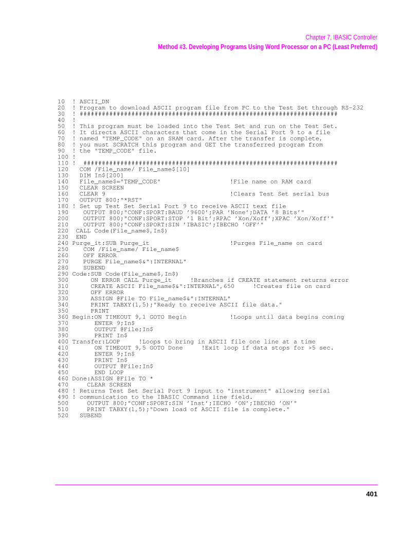
Chapter 7, IBASIC ControllerMethod #3. Developing Programs Using Word Processor on a PC (Least Preferred)
10 ! ASCII_DN20 ! Program to download ASCII program file from PC to the Test Set through RS-23230 ! ######################################################################40 !50 ! This program must be loaded into the Test Set and run on the Test Set.60 ! It directs ASCII characters that come in the Serial Port 9 to a file70 ! named "TEMP_CODE" on an SRAM card. After the transfer is complete,80 ! you must SCRATCH this program and GET the transferred program from90 ! the "TEMP_CODE" file.100 !110 ! #####################################################################120 COM /File_name/ File_name$[10]130 DIM In$[200]140 File_name$="TEMP_CODE" !File name on RAM card150 CLEAR SCREEN160 CLEAR 9 !Clears Test Set serial bus170 OUTPUT 800;"*RST"180 ! Set up Test Set Serial Port 9 to receive ASCII text file190 OUTPUT 800;"CONF:SPORT:BAUD ’9600’;PAR ’None’;DATA ’8 Bits’"200 OUTPUT 800;"CONF:SPORT:STOP ’1 Bit’;RPAC ’Xon/Xoff’;XPAC ’Xon/Xoff’"210 OUTPUT 800;"CONF:SPORT:SIN ’IBASIC’;IBECHO ’OFF’"220 CALL Code(File_name$,In$)230 END240 Purge_it:SUB Purge_it !Purges File_name on card250 COM /File_name/ File_name$260 OFF ERROR270 PURGE File_name$&":INTERNAL"280 SUBEND290 Code:SUB Code(File_name$,In$)300 ON ERROR CALL Purge_it !Branches if CREATE statement returns error310 CREATE ASCII File_name$&":INTERNAL",650 !Creates file on card320 OFF ERROR330 ASSIGN @File TO File_name$&":INTERNAL"340 PRINT TABXY(1,5);"Ready to receive ASCII file data."350 PRINT360 Begin:ON TIMEOUT 9,1 GOTO Begin !Loops until data begins coming370 ENTER 9;In$380 OUTPUT @File;In$390 PRINT In$400 Transfer:LOOP !Loops to bring in ASCII file one line at a time410 ON TIMEOUT 9,5 GOTO Done !Exit loop if data stops for >5 sec.420 ENTER 9;In$430 PRINT In$440 OUTPUT @File;In$450 END LOOP460 Done:ASSIGN @File TO *470 CLEAR SCREEN480 ! Returns Test Set Serial Port 9 input to "instrument" allowing serial490 ! communication to the IBASIC Command line field.500 OUTPUT 800;"CONF:SPORT:SIN ’Inst’;IECHO ’ON’;IBECHO ’ON’"510 PRINT TABXY(1,5);"Down load of ASCII file is complete."520 SUBEND
401
Chapter 7, IBASIC ControllerMethod #3. Developing Programs Using Word Processor on a PC (Least Preferred)
on
the
the t
.
n rate
Sending ASCII Text Files Over RS-232 With Windows Terminal
Set up the Windows Terminal emulator software on the PC as covered in "Setting Up Microsoft Windows Terminal on your PC (Windows Version 3.1)" on page 375. Load and run the ASCII_DN download program in the Test Set’s IBASIC controller. When the prompt Ready to receive ASCII file data is displayed on the Test Set, make the following settings in Windows Terminal the PC:
1. Select Settings.
2. Select Text Transfers.
3. Select Flow Control: Standard Flow Control.
4. Select Word Wrap Outgoing Text at Column: unselected.
This will use Xon/Xoff flow control by default.
5. Select OK.
6. Select Transfers.
7. Select Send Text File.
8. Set Strip LF off and Append LF off. (It is important that the line feeds that are in the ASCII file not be stripped or the file transfer will not work).
9. Select or enter the file name to transfer.
10. Begin the transfer by selecting OK.
At this point, each line of the program will rapidly scroll across the screen of Test Set. When the transfer is finished, the prompt Down load of ASCII file complete. will be displayed on the Test Set.
Before running the downloaded program, execute a SCRATCH command onIBASIC Command Line to remove the ASCII_DN download program from TesSet memory.
Next, execute a GET TEMP_CODE command on the IBASIC Command LineThis will load the ASCII text into the IBASIC program memory.
Finally, execute a RUN command on the IBASIC Command Line. This will ruthe program. If any syntax errors are present in the program IBASIC will genethe appropriate error messages.
402
Chapter 7, IBASIC ControllerMethod #3. Developing Programs Using Word Processor on a PC (Least Preferred)
“up”minal
nd
roll gram
BA-et
is
e e ap-
Sending ASCII Text Files over RS-232 with ProComm Communications Software
Set up the ProComm terminal emulator software on the PC as covered in "Setting Up ProComm Revision 2.4.3 on your PC" on page 377. On the Test Set, enter and run the ASCII_DN download program in the IBASIC controller. When the prompt Ready to receive ASCII file data is displayed on the Test Set, make the following settings in the ProComm terminal emulator on the PC:
NOTE: The ProComm terminal emulator views the file transfer as sending the file from the PCto the Test Set. This is opposite to the direction used by the previous Windows Terexample. Therefore, with ProComm an ASCII “upload” transfer is used.
1. Press Alt+F10 to display the ProComm help screen. 2. Press Alt+P to display the SETUP MENU. 3. Select item 6: ASCII TRANSFER SETUP. 4. Set Echo locally: NO. 5. Expand blank lines: YES. 6. Pace character: 0. 7. Character pacing: 15. 8. Line pacing: 10. 9. CR translation: NONE, LF. 10. Translation: NONE (This is important since the default setting will strip line feeds a
this will cause the transfer to never begin).11. Select the Escape key to exit setup mode and return to the main screen. 12. Press Alt F10 to access the help menu. 13. To begin sending the file, select PgUp. 14. In the UPLOAD screen, select 7 ASCII protocol. 15. Run the ASCII_DN download program on the Test Set. 16. When the Test Set displays Ready to receive ASCII file data, press Enter
on the PC to begin the transfer. At this point, each line of the program will rapidly scacross the screen of the Test Set. When the transfer is finished, the download prowill display Down load of ASCII file complete., and the program file will be stored on the SRAM card in the TEMP-CODE file.
17. Before running the transferred program, execute a SCRATCH command on the ISIC Command Line line to remove the ASCII_DN download program from Test Smemory.
18. Next, execute a GET TEMP_CODE command on the IBASIC Command Line. Thwill load the ASCII text into the IBASIC program memory.
19. Finally, execute a RUN command on the IBASIC Command Line. This will run thprogram. If any syntax errors are present in the program IBASIC will generate thpropriate error messages.
403
Chapter 7, IBASIC ControllerUploading Programs from the Test Set to a PC
Uploading Programs from the Test Set to a PC
As an overview, the following steps must be performed:
1. The Test Set must output the program over Serial Port 9.
2. The PC must receive the data through its serial port and direct the data to a file on disk. This can be done by a terminal emulator program such as Windows Terminal, ProComm, or HP AdvanceLink. This requires having the serial port connection established as outlined in "Interfacing to the IBASIC Controller using Serial Ports" on page 368.
To configure the Test Set to output the program to Serial Port 9 position the cursor on the IBASIC Command Line field. Execute the command PRINTER IS 9. This command sets Serial Port 9 as the default printer port. When PRINT commands are executed, ASCII characters will be sent to Serial Port 9.
On the PC, select Receive Text File in Windows Terminal or Receive Files (PgDn which is called Download) in ProComm. Enter a file name, then initiate the file transfer. The PC is now looking for ASCII text to come in the serial port.
Load the program to be transferred into the Test Set. Execute the IBASIC LIST command on the IBASIC Command Line. The program listing will be sent to Serial Port 9 and be received by the terminal emulator software on the PC. When the listing is finished, terminate the file transfer by selecting Stop on Windows or Escape on ProComm.
404
Chapter 7, IBASIC ControllerSerial I/O from IBASIC Programs
Serial I/O from IBASIC Programs
There are two serial ports available for I/O (input / output) to peripherals external to the Test Set. To bring data in to the Test Set through the serial port(s) use the IBASIC ENTER command. To send data out, use the OUTPUT command.
Serial Ports 9 and 10
The Test Set uses a small RJ-11 female connector on the rear panel for connecting to the two serial ports. This connector has six wires, 3 for Serial Port Address 9 and 3 for Serial Port Address 10. For information about serial port configuration, refer to the "Test Set Serial Port Configuration" on page 368. For connection information, refer to figure 26 on page 371.
Before using either port, the RS-232 protocol must be established by setting baud rate, pacing, and the other settings as explained in "Test Set Serial Port Configuration" on page 368. Functionally, from an I/O perspective, the two serial ports are identical. However, operationally there is one major difference. The Serial Port Address 9 settings are adjustable on the I/O CONFIGURE screen or with IBASIC commands, while the Serial Port 10 settings are adjustable only with IBASIC commands. There is no screen for Serial Port 10 settings. For more information, see Chapter 4, "HP-IB Commands" which gives the command syntax for Serial Port 9 and 10.
405
Chapter 7, IBASIC ControllerSerial I/O from IBASIC Programs
Example IBASIC Program Using Serial Port 10
The following program illustrates I/O to both serial ports. The program sends a prompt message to a terminal connected to Serial Port 9 and waits for a response from the user at the terminal. When the response is received from the terminal connected to Serial Port 9, a series of ASCII characters are sent out Serial Port 10.
10 !....ASCII CHARACTER CYCLER...........30 !....be connected to a terminal at 9600 baud.40 !....Outputs ASCII characters on Serial Port 10 beginning with
ASCII50 !......character 32 (space) and ending with ASCII character 126
(~).60 !......Characters are output with no CR/LF70 OUTPUT 9;"When you are ready to send data on port10,press ENTER"80 OUTPUT 800;"CONF:SPOR:SIN 'IBASIC';BAUD ‘9600'"90 !Allows IBASIC to read port 9100 DIM A$[10]110 ENTER 9;A$ !Program waits here until CR/LF is received.120 !........130 I=32140 HILE I<=126150 OUTPUT 10 USING "K,#";CHR$(I) 160 !Outputs characters all on one line.170 OUTPUT 10 USING "K,#";CHR$(I) 180 !Outputs characters all on one line.190 END WHILE200 OUTPUT 800;"CONF:SPOR:SIN 'Inst'" !Sets port 9 to IBASIC entryfield.180 EXECUTE ("CURSOR HOME") !Places cursor at left of IBASIC entryfield190 END
406
Chapter 7, IBASIC ControllerSerial I/O from IBASIC Programs
Serial
Port
SCII y
Serial Port 10 Information
Serial Port 10 is sometimes called Serial Port B in Test Set documentation and programs.
The default Serial Port 10 settings are the same as Serial Port 9. They are
1. Serial Baud rate: 9600
2. Parity: None
3. Data Length: 8 Bits
4. Stop Length: 1 Bit
5. Receive and Transmit Pacing: Xon/Xoff
6. Serial in: Not available for Port 10
7. IBASIC and Instrument Echo: Not available for Port 10
There is no Test Set screen that shows Serial Port 10’s settings. Therefore, to knowPort 10 settings, they must either be set or queried using IBASIC commands.
For example, the following IBASIC program queries the baud rate setting of Serial 10:
10 DIM Setting$[20]20 OUTPUT 800;"CONF:SPB:BAUD?" !Initiates a query.30 ENTER 800;Setting$40 DISP Setting$50 END
This program returns a quoted string. If the baud rate is set to 9600, the returned Acharacter string is 9600. Serial Port 10 settings are held in non-volatile memory. Theremain unchanged until modified using an IBASIC command.
407
Chapter 7, IBASIC ControllerPROGram Subsystem
Test
PROGram Subsystem
Introduction
The PROGram Subsystem provides a set of commands which allow an external controller to generate and control an IBASIC program within the Test Set. The PROGram Subsystem in the Test Set is a limited implementation of the PROGram Subsystem defined in the Standard Commands for Programmable Instruments (SCPI) Standard. The PROGram Subsystem commands, as implemented in the Test Set, can be used to
• download an IBASIC program from an external controller into the Test Set• upload an IBASIC program from the Test Set into an external controller• control an IBASIC program resident in the Test Set from an external controller• set or query program variables within an IBASIC program which is resident in the
Set• execute IBASIC commands in the Test Set’s IBASIC Controller from an external
controller
408
Chapter 7, IBASIC ControllerPROGram Subsystem
SCPI PROGram Subsystem
The SCPI PROGram Subsystem was designed to support instruments which can store multiple programs in RAM memory at the same time. The SCPI PROGram Subsystem provides commands which allow multiple programs to be named, defined and resident in the instrument at the same time. The Test Set does not support this capability.
For complete information on the SCPI PROGram Subsystem refer to the Standard Commands for Programmable Instruments (SCPI) Standard. If you are not familiar with SCPI, it is recommended that you obtain a copy of the book: A Beginner’s Guide to SCPI (ISBN 0-201-56350, Addison-Wesley Publishing Company).
Test Set PROGram Subsystem
The Test Set was designed to store only one IBASIC program in RAM memory at any given time. The PROGram Subsystem commands, as implemented in the Test Set, operate differently than described in the SCPI Standard. In addition, the SCPI PROGram Subsystem commands which were designed to support multiple programs are not supported in the Test Set.
Supported SCPI Commands
The Test Set supports the following subset of the :SELected SCPI commands.
• :SELected:DEFine• :SELected:DEFine?• :SELected:DELete:ALL• :SELected:EXECute• :SELected:NUMBer• :SELected:NUMBer?• :SELected:STATe• :SELected:STATe?• :SELected:STRing• :SELected:STRing?• :SELected:WAIT
409
Chapter 7, IBASIC ControllerPROGram Subsystem
ds cant Set’s
Unsupported SCPI Commands
The Test Set does not support the following SCPI commands.
• :CATalog?• :SELected:DELete:SELected• :SELected:MALLocate• :SELected:MALLocate?• :SELected:NAME• :SELected:NAME?• :EXPLicit:DEFine• :EXPLicit:DEFine?• :EXPLicit:DELete• :EXPLicit:EXECute• :EXPLicit:MALLocate• :EXPLicit:MALLocate?• :EXPLicit:NUMBer• :EXPLicit:NUMBer?• :EXPLicit:STATe• :EXPLicit:STATe?• :EXPLicit:STRing• :EXPLicit:STRing?• :EXPLicit:WAIT
NOTE: Sending the Test Set any of the unsupported SCPI PROGram Subsystem commanresult in unexpected and/or erroneous operation of IBASIC. This may require the TesRAM to be initialized from the SERVICE screen to regain proper IBASIC operation.
410
Chapter 7, IBASIC ControllerPROGram Subsystem
om anut in
o the
PROGram Subsystem Commands
See the Program syntax diagram, on page 163, for PROGram Subsystem command syntax rules.
Command Notation
The following notation is used in the command descriptions:
Letter case (uppercase or lowercase) is used to differentiate between the short form (the uppercase characters) and long form (the whole keyword) of the command.
The lower case letters in the keyword are optional; they can be deleted and the com-mand will still be understood by the Test Set.
[] = Optional keyword; this is the default state, the Test Set will process the command to have the same effect whether the optional keyword is included by the programmer or not.
<> = Specific SCPI-defined parameter types. Refer to the SCPI Standard for definitions of the SCPI-defined parameter types.
= One or more parameters that must be included one or more times.
| = Separator for choices for a parameter. Can be read the same as “or.”
Command Descriptions
NOTE: When a PROGram Subsystem command is sent to the Test Set through HP-IB frexternal controller the Test Set is put into REMOTE mode. The Test Set must be pLOCAL mode to use the front-panel keys or to use the serial ports to input data intIBASIC Command line.
411
Chapter 7, IBASIC ControllerPROGram Subsystem
[:SELected] All the commands under this keyword access the IBASIC program currently resident in the Test Set. Note that this keyword is optional in the command syntax.
Syntax
PROGram[:SELected]
:DEFine <program> The DEFine command is used to create and download an IBASIC program into the Test Set from an external controller.
To download an IBASIC program, any currently resident IBASIC program must first be deleted using the :DELete:ALL command. Attempting to download a new IBASIC program while an IBASIC program is currently resident causesIBASIC Error: -282 Illegal program name.
NOTE: It is possible for the PROGram Subsystem to think that there is an IBASIC programresident in the Test Set when, in actuality, there is not. This situation would exist forexample, if an IBASIC program had been created and downloaded using the :DEFinecommand and then deleted, from the front panel, using the SCRATCH ALL commandfrom the IBASIC Command line. Under this circumstance IBASIC Error -282 would begenerated when another attempt is made to download a program with the PROGramSubsystem. It is recommended that the :DELete:ALL command always be sentimmediately before the :DEFine command.
The IBASIC program downloaded into the Test Set must be transferred as IEEE 488.2 Arbitrary Block Program Data. Refer to the IEEE Standard 488.2-1987 for detailed information on this data type. Two syntax forms are provided with the Arbitrary Block Program Data data type: one form if the length of the program is known and another one if it is not.
412
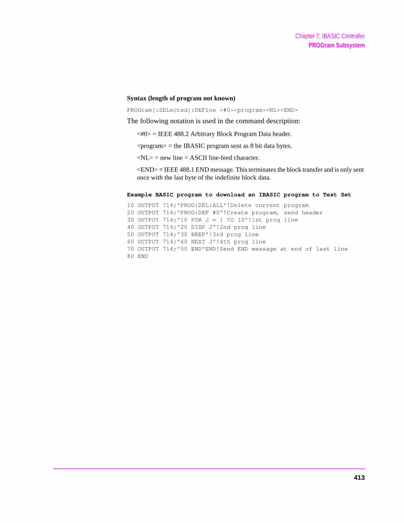
Chapter 7, IBASIC ControllerPROGram Subsystem
Syntax (length of program not known)
PROGram[:SELected]:DEFine <#0><program><NL><END>
The following notation is used in the command description:
<#0> = IEEE 488.2 Arbitrary Block Program Data header.
<program> = the IBASIC program sent as 8 bit data bytes.
<NL> = new line = ASCII line-feed character.
<END> = IEEE 488.1 END message. This terminates the block transfer and is only sent once with the last byte of the indefinite block data.
Example BASIC program to download an IBASIC program to Test Set
10 OUTPUT 714;"PROG:DEL:ALL"!Delete current program20 OUTPUT 714;"PROG:DEF #0"!Create program, send header30 OUTPUT 714;"10 FOR J = 1 TO 10"!1st prog line40 OUTPUT 714;"20 DISP J"!2nd prog line50 OUTPUT 714;"30 BEEP"!3rd prog line60 OUTPUT 714;"40 NEXT J"!4th prog line70 OUTPUT 714;"50 END"END!Send END message at end of last line80 END
413
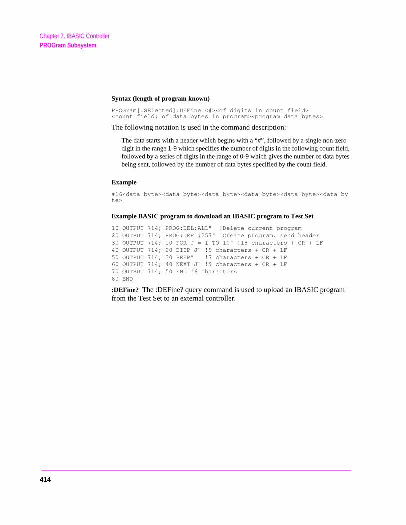
Chapter 7, IBASIC ControllerPROGram Subsystem
ero ld, ytes
Syntax (length of program known)
PROGram[:SELected]:DEFine <#><of digits in count field><count field: of data bytes in program><program data bytes>
The following notation is used in the command description:
The data starts with a header which begins with a “#”, followed by a single non-zdigit in the range 1-9 which specifies the number of digits in the following count fiefollowed by a series of digits in the range of 0-9 which gives the number of data bbeing sent, followed by the number of data bytes specified by the count field.
Example
#16<data byte><data byte><data byte><data byte><data byte><data byte>
Example BASIC program to download an IBASIC program to Test Set
10 OUTPUT 714;"PROG:DEL:ALL" !Delete current program20 OUTPUT 714;"PROG:DEF #257" !Create program, send header30 OUTPUT 714;"10 FOR J = 1 TO 10" !18 characters + CR + LF40 OUTPUT 714;"20 DISP J" !9 characters + CR + LF50 OUTPUT 714;"30 BEEP" !7 characters + CR + LF60 OUTPUT 714;"40 NEXT J" !9 characters + CR + LF70 OUTPUT 714;"50 END"!6 characters80 END
:DEFine? The :DEFine? query command is used to upload an IBASIC program from the Test Set to an external controller.
414
Chapter 7, IBASIC ControllerPROGram Subsystem
ero ld, ytes
ntrol-
The IBASIC program uploaded to the external controller is transferred as IEEE 488.2 Definite Length Arbitrary Block Response Data. The following information describes some of the characteristics of the IEEE 488.2 Definite Length Arbitrary Block Response Data type. Refer to the IEEE Standard 488.2-1987 for detailed information on this data type.
The data starts with a header which begins with a “#”, followed by a single non-zdigit in the range 1-9 which specifies the number of digits in the following count fiefollowed by a series of digits in the range of 0-9 which gives the number of data bbeing sent, followed by the number of data bytes specified by the count field.
Example
#16<data byte><data byte><data byte><data byte><data byte><databyte>
The transfer is terminated by the transmission, from the Test Set to the external coler, of the response message terminator (NL & END messge).
<NL> = new line = ASCII linefeed character.
<END> = IEEE 488.1 END message.
Syntax
PROGram[:SELected]:DEFine?
415
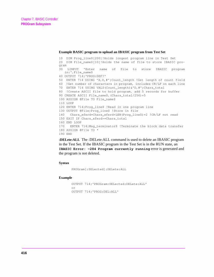
Chapter 7, IBASIC ControllerPROGram Subsystem
Example BASIC program to upload an IBASIC program from Test Set
10 DIM Prog_line$[200]!Holds longest program line in Test Set20 DIM File_name$[10]!Holds the name of file to store IBASIC pro-gram30 LINPUT "Enter name of file to store IBASIC program
in:",File_name$40 OUTPUT 714;"PROG:DEF?"50 ENTER 714 USING "X,D,#";Count_length !Get length of count field60 !Get number of characters in program, includes CR/LF on each line70 ENTER 714 USING VAL$(Count_length)&"D,#";Chars_total80 !Create ASCII file to hold program, add 5 records for buffer90 CREATE ASCII File_name$,(Chars_total/256)+5100 ASSIGN @File TO File_name$110 LOOP120 ENTER 714;Prog_line$ !Read in one program line130 OUTPUT @File;Prog_line$ !Store in file140 Chars_xferd=Chars_xferd+LEN(Prog_line$)+2 !CR/LF not read150 EXIT IF Chars_xferd>=Chars_total160 END LOOP170 ENTER 714;Msg_terminator$ !Terminate the block data transfer180 ASSIGN @File TO *190 END
:DELete:ALL The :DELete:ALL command is used to delete an IBASIC program in the Test Set. If the IBASIC program in the Test Set is in the RUN state, an IBASIC Error: -284 Program currently running error is generated and the program is not deleted.
Syntax
PROGram[:SELected]:DELete:ALL
Example
OUTPUT 714;"PROGram:SELected:DELete:ALL" or
OUTPUT 714;"PROG:DEL:ALL"
416

Chapter 7, IBASIC ControllerPROGram Subsystem
e
ate d. If
:EXECute <program_command> The :EXECute command is used to execute, from an external controller, an IBASIC program command in the Test Set’s built-in IBASIC Controller.
<program_command> is string data representing any legal IBASIC command. If thstring data does not represent a legal IBASIC command, an IBASIC Error: -285 Program syntax error is generated.
Any IBASIC program in the Test Set must be in either the PAUSed or STOPped stbefore the external controller issues the :EXECute <program_command> commanthe IBASIC program is in the RUN state, an IBASIC Error: -284 Program currently running is generated.
Syntax
PROGram[:SELected]:EXECute <delimiter><program_command><delimiter>
The following notation is used in the command description:
<delimiter> = IEEE 488.2 <string data> delimiter, single quote or double quote, must be the same.
Example
OUTPUT 714;"PROGram:SELected:EXECute ’CLEAR SCREEN’" orOUTPUT 714;"PROG:EXEC ’CLEAR SCREEN’"
417

Chapter 7, IBASIC ControllerPROGram Subsystem
:NUMber <varname>,<nvalues> The :NUMBer command is used to set, from an external controller, the value of numeric variables or arrays in an IBASIC program in the Test Set. <varname> is the name of an existing numeric variable or array, and can be sent as either character data (<varname> not enclosed in quotes) or string data (<varname> enclosed in quotes). <nvalues> is a list of comma-separated <numeric_values> which are used to set the value of <varname>.
NOTE: If the variable name <var_name> is longer than 12 characters it must be sent as string data(<var_name> enclosed in quotes). For example, OUTPUT 714;"PROG:NUMB’Var_name’,10".
Attempting to send a <var_name> longer than 12 characters as character data(<var_name> not enclosed in quotes) will generate the following error:
HP-IB Error: -112 Program mnemonic too long.
If an attempt is made to set the value of a numeric variable or array and no IBASIC program is in the Test Set an IBASIC Error: -282 Illegal program name is generated. If an attempt is made to set the value of a numeric variable or array and the numeric variable specified in <varname> does not exist in the program an IBASIC Error: -283 Illegal variable name is generated. If the specified numeric variable cannot hold all of the specified <numeric_values> an IBASIC Error: -108 Parameter not allowed is generated.
Syntax
PROGram[:SELected]:NUMBer <varname>,<nvalues>
Example setting the value of a simple variable
OUTPUT 714;"PROGram:SELected:NUMBer Variable,15" orOUTPUT 714;"PROG:NUMB Variable,15"
Example setting the value of a one dimensional array [Array(5)] with 6 elements
OUTPUT 714;"PROGram:SELected:NUMBer Array,0,1,2,3,4,5"orOUTPUT 714;"PROG:NUMB Array,0,1,2,3,4,5"
NOTE: Individual array elements cannot be set with the :NUMBer command.
418
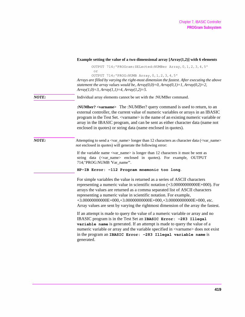
Chapter 7, IBASIC ControllerPROGram Subsystem
Example setting the value of a two dimensional array [Array(1,2)] with 6 elements
OUTPUT 714;"PROGram:SELected:NUMBer Array,0,1,2,3,4,5" orOUTPUT 714;"PROG:NUMB Array,0,1,2,3,4,5"
Arrays are filled by varying the right-most dimension the fastest. After executing the abovestatement the array values would be, Array(0,0)=0, Array(0,1)=1, Array(0,2)=2,Array(1,0)=3, Array(1,1)=4, Array(1,2)=5.
NOTE: Individual array elements cannot be set with the :NUMBer command.
:NUMber? <varname> The :NUMBer? query command is used to return, to an external controller, the current value of numeric variables or arrays in an IBASIC program in the Test Set. <varname> is the name of an existing numeric variable or array in the IBASIC program, and can be sent as either character data (name not enclosed in quotes) or string data (name enclosed in quotes).
NOTE: Attempting to send a <var_name> longer than 12 characters as character data (<var_name>not enclosed in quotes) will generate the following error:
If the variable name <var_name> is longer than 12 characters it must be sent asstring data (<var_name> enclosed in quotes). For example, OUTPUT714;"PROG:NUMB ’Var_name’".
HP-IB Error: -112 Program mnemonic too long.
For simple variables the value is returned as a series of ASCII characters representing a numeric value in scientific notation (+3.00000000000E+000). For arrays the values are returned as a comma separated list of ASCII characters representing a numeric value in scientific notation. For example,+3.00000000000E+000,+3.00000000000E+000,+3.00000000000E+000, etc.Array values are sent by varying the rightmost dimension of the array the fastest.
If an attempt is made to query the value of a numeric variable or array and no IBASIC program is in the Test Set an IBASIC Error: -283 Illegal variable name is generated. If an attempt is made to query the value of a numeric variable or array and the variable specified in <varname> does not exist in the program an IBASIC Error: -283 Illegal variable name is generated.
419
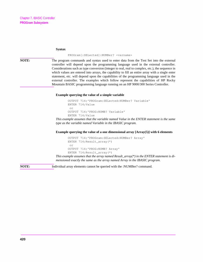
Chapter 7, IBASIC ControllerPROGram Subsystem
Syntax
PROGram[:SELected]:NUMBer? <varname>
NOTE: The program commands and syntax used to enter data from the Test Set into the externalcontroller will depend upon the programming language used in the external controller.Considerations such as type conversion (integer to real, real to complex, etc.), the sequence inwhich values are entered into arrays, the capability to fill an entire array with a single enterstatement, etc. will depend upon the capabilities of the programming language used in theexternal controller. The examples which follow represent the capabilities of HP RockyMountain BASIC programming language running on an HP 9000/300 Series Controller.
Example querying the value of a simple variable
OUTPUT 714;"PROGram:SELected:NUMBer? Variable"ENTER 714;Value orOUTPUT 714;"PROG:NUMB? Variable"ENTER 714;Value
This example assumes that the variable named Value in the ENTER statement is the sametype as the variable named Variable in the IBASIC program.
Example querying the value of a one dimensional array [Array(5)] with 6 elements
OUTPUT 714;"PROGram:SELected:NUMBer? Array"ENTER 714;Result_array(*) orOUTPUT 714;"PROG:NUMB? Array"ENTER 714;Result_array(*)
This example assumes that the array named Result_array(*) in the ENTER statement is di-mensioned exactly the same as the array named Array in the IBASIC program.
NOTE: Individual array elements cannot be queried with the :NUMBer? command.
420
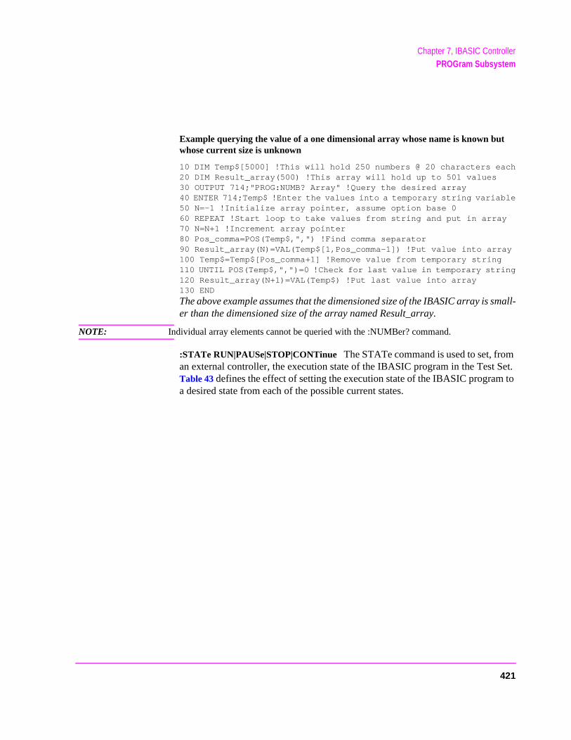
Chapter 7, IBASIC ControllerPROGram Subsystem
Example querying the value of a one dimensional array whose name is known but whose current size is unknown
10 DIM Temp$[5000] !This will hold 250 numbers @ 20 characters each20 DIM Result_array(500) !This array will hold up to 501 values30 OUTPUT 714;"PROG:NUMB? Array" !Query the desired array40 ENTER 714;Temp$ !Enter the values into a temporary string variable50 N=-1 !Initialize array pointer, assume option base 060 REPEAT !Start loop to take values from string and put in array70 N=N+1 !Increment array pointer80 Pos_comma=POS(Temp$,",") !Find comma separator90 Result_array(N)=VAL(Temp$[1,Pos_comma-1]) !Put value into array100 Temp$=Temp$[Pos_comma+1] !Remove value from temporary string110 UNTIL POS(Temp$,",")=0 !Check for last value in temporary string120 Result_array(N+1)=VAL(Temp$) !Put last value into array130 END
The above example assumes that the dimensioned size of the IBASIC array is small-er than the dimensioned size of the array named Result_array.
NOTE: Individual array elements cannot be queried with the :NUMBer? command.
:STATe RUN|PAUSe|STOP|CONTinue The STATe command is used to set, from an external controller, the execution state of the IBASIC program in the Test Set. Table 43 defines the effect of setting the execution state of the IBASIC program to a desired state from each of the possible current states.
421
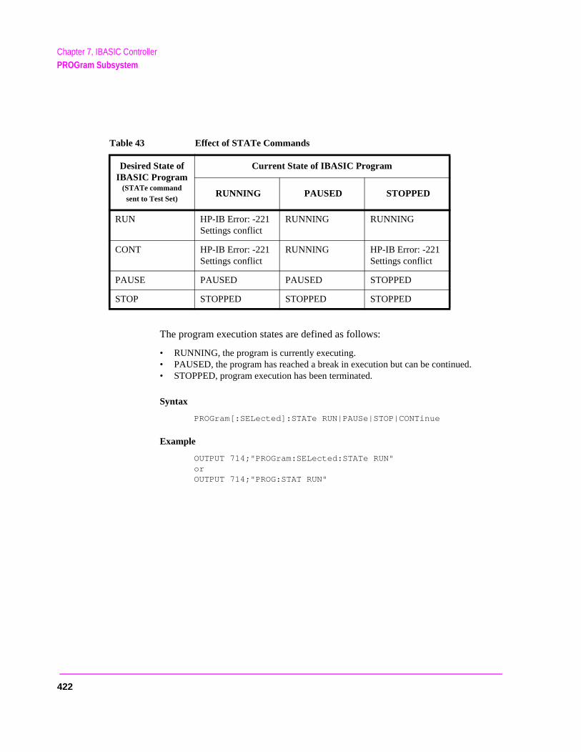
Chapter 7, IBASIC ControllerPROGram Subsystem
The program execution states are defined as follows:
• RUNNING, the program is currently executing.• PAUSED, the program has reached a break in execution but can be continued.• STOPPED, program execution has been terminated.
Syntax
PROGram[:SELected]:STATe RUN|PAUSe|STOP|CONTinue
Example
OUTPUT 714;"PROGram:SELected:STATe RUN" or
OUTPUT 714;"PROG:STAT RUN"
Table 43 Effect of STATe Commands
Desired State of IBASIC Program
(STATe command sent to Test Set)
Current State of IBASIC Program
RUNNING PAUSED STOPPED
RUN HP-IB Error: -221 Settings conflict
RUNNING RUNNING
CONT HP-IB Error: -221 Settings conflict
RUNNING HP-IB Error: -221 Settings conflict
PAUSE PAUSED PAUSED STOPPED
STOP STOPPED STOPPED STOPPED
422
Chapter 7, IBASIC ControllerPROGram Subsystem
:STATe? The STATe? query command is used to query, from an external controller, the current execution state of the IBASIC program in the Test Set. The return data (RUN, STOP, or PAUS) is sent as a series of ASCII characters.
The program execution states are defined as follows:
• RUN, the program is currently executing.• PAUS, the program has reached a break in execution but can be continued.• STOP, program execution has been terminated.
Syntax
PROGram[:SELected]:STATe?
Example
OUTPUT 714;"PROGram:SELected:STATe?"ENTER 714;State$
orOUTPUT 714;"PROG:STAT?"ENTER 714;State$
423
Chapter 7, IBASIC ControllerPROGram Subsystem
ringsed in
:STRing <varname>,<svalues> The :STRing command is used to set, from an external controller, the value of string variables or string arrays in an IBASIC program in the Test Set. <varname> is the name of an existing string variable or string array in the IBASIC program. <svalues> is a list of comma-separated quoted strings which are used to set the value of <varname>.
NOTE: If the variable name <var_name> is longer than 12 characters it must be sent as string data(<var_name> enclosed in quotes). For example, OUTPUT 714;"PROG:STR’Var_name’,’data’".
Attempting to send a <var_name> longer than 12 characters as character data(<var_name> not enclosed in quotes) will generate the following error:
HP-IB Error: -112 Program mnemonic too long.
NOTE: If the programmer wishes to append the IBASIC “$” string identifier onto the stvariable name, the string variable name must be sent as string data, that is encloquotes. For example,OUTPUT 714;"PROG:STR 'Var_name$','data'"
Appending the IBASIC “$” string identifier onto the string variable namewithout enclosing the string variable name in quotes will generateHP-IB Error: -101 Invalid character.
If an attempt is made to set the value of a string variable or array and no IBASIC program is in the Test Set an IBASIC Error: -282 Illegal program name is generated. If an attempt is made to set the value of a string variable or array and the string variable specified in <varname> does not exist in the program an IBASIC Error: -283 Illegal variable name is generated. If a quoted string value is too long to fit into the string variable then it is silently truncated when stored into the IBASIC string variable. If the specified string variable cannot hold all of the quoted strings an IBASIC Error: -108 Parameter not allowed is generated.
424
Chapter 7, IBASIC ControllerPROGram Subsystem
abletes. For
Syntax
PROGram[:SELected]:STRing <varname>,<svalues>
Example setting the value of a simple string variable
OUTPUT 714;"PROGram:SELected:STRing Variable,’data’" or
OUTPUT 714;"PROG:STR Variable,’data’"
Example of setting the value of a string array with 3 elements of 5 characters each, such as Array$(2)[5]
OUTPUT 714;"PROGram:SELected:STRing Array,’12345’,’12345’,’12345’"
or
OUTPUT 714;"PROG:STR Array,’12345’,’12345’,’12345’"
NOTE: With Option Base 0 set in IBASIC, array indexing starts at 0.
:STRing? <varname> The :STRing? query command is used to return, to an external controller, the current value of string variables or arrays in an IBASIC program in the Test Set. <varname> is the name of an existing string variable or string array in the IBASIC program.
NOTE: If the variable name <var_name> is longer than 12 characters it must be sent as string data(<var_name> enclosed in quotes). For example, OUTPUT 714;"PROG:STR? ’Var_name’".
Attempting to send a <var_name> longer than 12 characters as character data(<var_name> not enclosed in quotes) will generate the following error:
HP-IB Error: -112 Program mnemonic too long
NOTE: If the programmer wishes to append the IBASIC ‘$’ string identifier onto the string variname, the string variable name must be sent as string data, that is enclosed in quoexample,
OUTPUT 714;"PROG:STR? 'Var_name$'"
Appending the IBASIC ‘$’ string identifier onto the string variable name withoutenclosing the string variable name in quotes will generate the following error:HP-IB Error: -101 Invalid character.
425

Chapter 7, IBASIC ControllerPROGram Subsystem
of
.
SIC
and
For simple string variables the value is returned as a quoted string (“This is an example.”). For string arrays the values are returned as a comma separated listquoted strings (“This is an example.”,“This is an example.”). The string array elements are returned in ascending order (Array$(0), Array$(1), Array$(2), etc.)
If an attempt is made to query the value of a string variable or array and no IBAprogram is in the Test Set an IBASIC Error: -283 Illegal variable name is generated. If an attempt is made to query the value of a string variable or array the string variable specified in <varname> does not exist in the program an IBASIC Error: -283 Illegal variable name is generated.
Syntax
PROGram[:SELected]:STRing? <varname>
NOTE: The program commands and syntax used to enter string data from the Test Set into the externalcontroller will depend upon the programming language used in the external controller. Theexamples which follow represent the capabilities of HP Rocky Mountain BASIC programminglanguage running on an HP 9000/300 Series Controller.
Example of querying the value of a simple string variable
OUTPUT 714;"PROGram:SELected:STRing? Variable"ENTER 714;Value$ orOUTPUT 714;"PROG:STR? Variable"ENTER 714;Value$
Example of querying the value of a string array with 3 elements of 5 characters each, such as Array$(2)[5]
OUTPUT 714;"PROGram:SELected:STRing? Array"ENTER 714 USING "3(X,5A,2X)";Result_array$(*)
orOUTPUT 714;"PROG:STR? Array"ENTER 714 USING "3(X,5A,2X)";Result_array$(*)
This example assumes that the string array named Result_array$(*) is dimensioned exactly thesame as the array named Array in the IBASIC program and that each element in the string ar-ray Array has five characters in it.
426
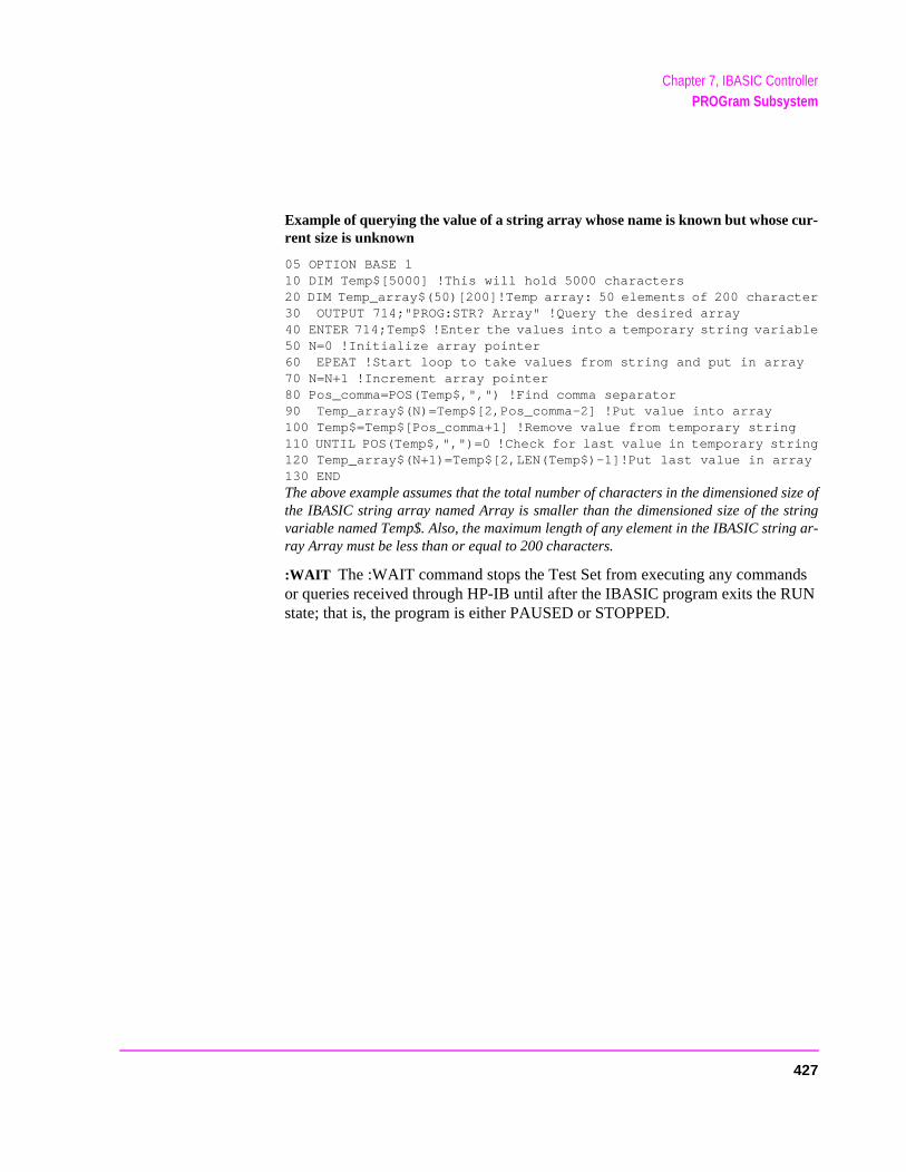
Chapter 7, IBASIC ControllerPROGram Subsystem
Example of querying the value of a string array whose name is known but whose cur-rent size is unknown
05 OPTION BASE 110 DIM Temp$[5000] !This will hold 5000 characters20 DIM Temp_array$(50)[200]!Temp array: 50 elements of 200 character30 OUTPUT 714;"PROG:STR? Array" !Query the desired array40 ENTER 714;Temp$ !Enter the values into a temporary string variable50 N=0 !Initialize array pointer60 EPEAT !Start loop to take values from string and put in array70 N=N+1 !Increment array pointer80 Pos_comma=POS(Temp$,",") !Find comma separator90 Temp_array$(N)=Temp$[2,Pos_comma-2] !Put value into array100 Temp$=Temp$[Pos_comma+1] !Remove value from temporary string110 UNTIL POS(Temp$,",")=0 !Check for last value in temporary string120 Temp_array$(N+1)=Temp$[2,LEN(Temp$)-1]!Put last value in array130 ENDThe above example assumes that the total number of characters in the dimensioned size ofthe IBASIC string array named Array is smaller than the dimensioned size of the stringvariable named Temp$. Also, the maximum length of any element in the IBASIC string ar-ray Array must be less than or equal to 200 characters.
:WAIT The :WAIT command stops the Test Set from executing any commands or queries received through HP-IB until after the IBASIC program exits the RUN state; that is, the program is either PAUSED or STOPPED.
427
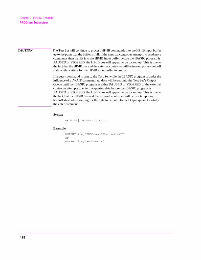
Chapter 7, IBASIC ControllerPROGram Subsystem
CAUTION: The Test Set will continue to process HP-IB commands into the HP-IB input buffer up to the point that the buffer is full. If the external controller attempts to send more commands than can fit into the HP-IB input buffer before the IBASIC program is PAUSED or STOPPED, the HP-IB bus will appear to be locked up. This is due to the fact that the HP-IB bus and the external controller will be in a temporary holdoff state while waiting for the HP-IB input buffer to empty.
If a query command is sent to the Test Set while the IBASIC program is under the influence of a :WAIT command, no data will be put into the Test Set’s Output Queue until the IBASIC program is either PAUSED or STOPPED. If the external controller attempts to enter the queried data before the IBASIC program is PAUSED or STOPPED, the HP-IB bus will appear to be locked up. This is due to the fact that the HP-IB bus and the external controller will be in a temporary holdoff state while waiting for the data to be put into the Output queue to satisfy the enter command.
Syntax
PROGram[:SELected]:WAIT
Example
OUTPUT 714;"PROGram:SELected:WAIT" or
OUTPUT 714;"PROG:WAIT"
428
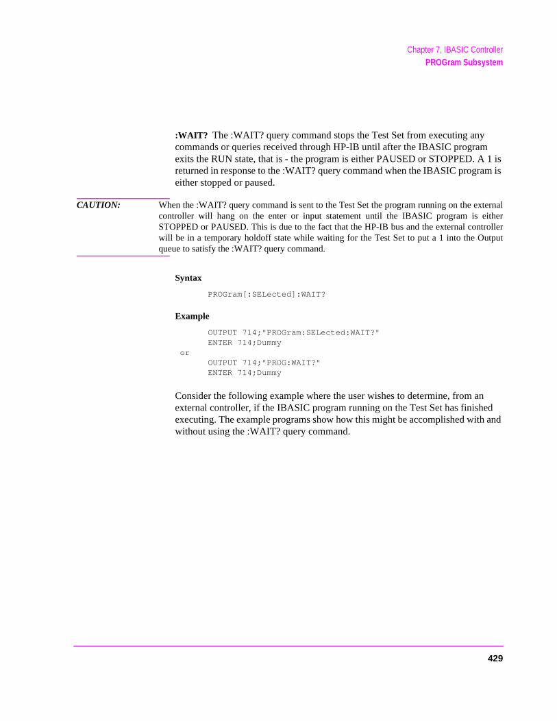
Chapter 7, IBASIC ControllerPROGram Subsystem
:WAIT? The :WAIT? query command stops the Test Set from executing any commands or queries received through HP-IB until after the IBASIC program exits the RUN state, that is - the program is either PAUSED or STOPPED. A 1 is returned in response to the :WAIT? query command when the IBASIC program is either stopped or paused.
CAUTION: When the :WAIT? query command is sent to the Test Set the program running on the externalcontroller will hang on the enter or input statement until the IBASIC program is eitherSTOPPED or PAUSED. This is due to the fact that the HP-IB bus and the external controllerwill be in a temporary holdoff state while waiting for the Test Set to put a 1 into the Outputqueue to satisfy the :WAIT? query command.
Syntax
PROGram[:SELected]:WAIT?
Example
OUTPUT 714;"PROGram:SELected:WAIT?"ENTER 714;Dummy
orOUTPUT 714;"PROG:WAIT?"ENTER 714;Dummy
Consider the following example where the user wishes to determine, from an external controller, if the IBASIC program running on the Test Set has finished executing. The example programs show how this might be accomplished with and without using the :WAIT? query command.
429
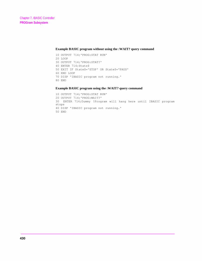
Chapter 7, IBASIC ControllerPROGram Subsystem
Example BASIC program without using the :WAIT? query command
10 OUTPUT 714;"PROG:STAT RUN"20 LOOP30 OUTPUT 714;"PROG:STAT?"40 ENTER 714;State$50 EXIT IF State$="STOP" OR State$="PAUS"60 END LOOP70 DISP "IBASIC program not running."80 END
Example BASIC program using the :WAIT? query command
10 OUTPUT 714;"PROG:STAT RUN"20 OUTPUT 714;"PROG:WAIT?"30 ENTER 714;Dummy !Program will hang here until IBASIC programstops40 DISP "IBASIC program not running."50 END
430
Chapter 7, IBASIC ControllerPROGram Subsystem
one nd
ram
tes.
Using the EXECute Command
The PROGram:EXECute command can be used to list, edit and control IBASIC programs in the Test Set from an external controller. This eliminates having to use the cursor control knob and provides a more efficient way of making small changes to programs. The full range of IBASIC program commands can be executed from an external controller using the PROGram:EXECute command.
The following operations are given as typical examples of using the PROGram:EXECute command.
NOTE: The program commands and syntax used to send data from the external controller to the TestSet will depend upon the programming language used in the external controller. The exampleswhich follow represent the capabilities of HP Rocky Mountain BASIC programming languagerunning on an HP 9000/300 Series Controller.
When a PROGram Subsystem command is sent to the Test Set through HP-IB froman external controller the Test Set is put into REMOTE mode. The Test Set must beput in LOCAL mode to use the front panel keys or to use the serial ports to inputdata into the IBASIC Command line.
Entering a new IBASIC program line
IBASIC program lines can be entered directly into the Test Set’s RAM memory,line at a time, from an external controller using the PROGram:EXECute commaas follows:
PROG:EXEC ’<new program line number/program line>’
where <new program line number/program line> represents a valid IBASIC progline.
For example, to enter the following new program line into the Test Set,
20 A=3.14
execute the following command from the external controller:
OUTPUT 714;"PROG:EXEC ’20 A=3.14’"
Quoted strings, such as those used in PRINT commands, must use double quoFor example,
OUTPUT 714;"PROG:EXEC ’30 PRINT ""TEST""’"
431

Chapter 7, IBASIC ControllerPROGram Subsystem
ory
e
Editing an existing IBASIC program line
Existing IBASIC program lines which are resident in the Test Set’s RAM memcan be edited, one line at a time, from an external controller using the PROGram:EXECute command as follows:
PROG:EXEC ’<existing program line number/modified program line>’
where <existing program line number/modified program line> represents an existing IBASIC program line.
For example, to edit the following existing program line in the Test Set.
30 OUTPUT 814;"AFAN:DEMP:GAIN 20 dB"to30 OUTPUT 814;"AFAN:DEMP:GAIN 10 dB"
execute the following command from the external controller:
OUTPUT 714;"PROG:EXEC ’30 OUTPUT 814;""AFAN:DEMP:GAIN 10 dB""’"
Quoted strings, such as those used in OUTPUT commands, must use doublquotes.
Listing A Program
Execute the following command on the external controller to list an IBASIC program which is resident in the Test Set to the currently specified IBASIC Controller LIST device.
OUTPUT 714;"PROG:EXEC ’LIST’"
432
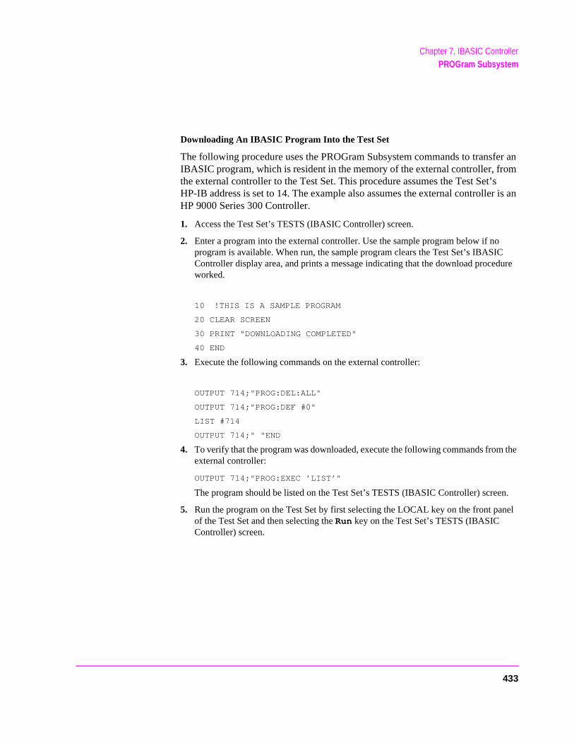
Chapter 7, IBASIC ControllerPROGram Subsystem
sr is an
C dure
the
n.
nel
Downloading An IBASIC Program Into the Test Set
The following procedure uses the PROGram Subsystem commands to transfer an IBASIC program, which is resident in the memory of the external controller, from the external controller to the Test Set. This procedure assumes the Test Set’HP-IB address is set to 14. The example also assumes the external controlleHP 9000 Series 300 Controller.
1. Access the Test Set’s TESTS (IBASIC Controller) screen.
2. Enter a program into the external controller. Use the sample program below if noprogram is available. When run, the sample program clears the Test Set’s IBASIController display area, and prints a message indicating that the download proceworked.
10 !THIS IS A SAMPLE PROGRAM
20 CLEAR SCREEN
30 PRINT "DOWNLOADING COMPLETED"
40 END
3. Execute the following commands on the external controller:
OUTPUT 714;"PROG:DEL:ALL"
OUTPUT 714;"PROG:DEF #0"
LIST #714
OUTPUT 714;" "END
4. To verify that the program was downloaded, execute the following commands fromexternal controller:
OUTPUT 714;"PROG:EXEC ’LIST’"
The program should be listed on the Test Set’s TESTS (IBASIC Controller) scree
5. Run the program on the Test Set by first selecting the LOCAL key on the front paof the Test Set and then selecting the Run key on the Test Set’s TESTS (IBASIC Controller) screen.
433
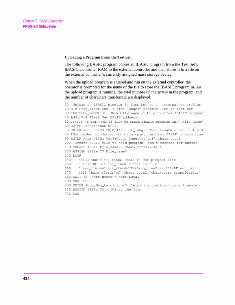
Chapter 7, IBASIC ControllerPROGram Subsystem
n
As , and
Uploading a Program From the Test Set
The following BASIC program copies an IBASIC program from the Test Set’sIBASIC Controller RAM to the external controller and then stores it to a file othe external controller’s currently assigned mass storage device.
When the upload program is entered and run on the external controller, the operator is prompted for the name of the file to store the IBASIC program in. the upload program is running, the total number of characters in the programthe number of characters transferred, are displayed.
10 !Upload an IBASIC program in Test Set to an external controller.20 DIM Prog_line$[200] !Holds longest program line in Test Set30 DIM File_name$[10] !Holds the name of file to store IBASIC program40 Addr=714 !Test Set HP-IB address50 LINPUT "Enter name of file to store IBASIC program in:",File_name$60 OUTPUT Addr;"PROG:DEF?"70 ENTER Addr USING "X,D,#";Count_length !Get length of count field80 !Get number of characters in program, includes CR/LF on each line90 ENTER Addr USING VAL$(Count_length)&"D,#";Chars_total100 !Create ASCII file to hold program, add 5 records for buffer110 CREATE ASCII File_name$,(Chars_total/256)+5120 ASSIGN @File TO File_name$130 LOOP140 ENTER Addr;Prog_line$ !Read in one program line150 OUTPUT @File;Prog_line$ !Store in file160 Chars_xferd=Chars_xferd+LEN(Prog_line$)+2 !CR/LF not read170 DISP Chars_xferd;"of";Chars_total;"characters transferred."180 EXIT IF Chars_xferd>=Chars_total190 END LOOP200 ENTER Addr;Msg_terminator$ !Terminate the block data transfer210 ASSIGN @File TO * !Close the file220 END
434
Chapter 7, IBASIC ControllerPROGram Subsystem
nel
Saving an IBASIC Program To A Memory Card
The following procedure can be used to save an IBASIC program from the IBASIC Controller’s RAM memory to a memory card inserted into the front paof the Test Set.
1. Press LOCAL, SHIFT, CANCEL on the Test Set to perform an IBASIC reset.
2. If the memory card has not been initialized, insert it into the Test Set and execute the following command on the external controller:
OUTPUT 714;"PROG:EXEC ’INITIALIZE"":INTERNAL,4""’"
3. Insert the initialized memory card into the Test Set.
4. Define the memory card as the Mass Storage device by executing the following command on the external controller:
OUTPUT 714;"PROG:EXEC ’MSI "":INTERNAL,4""’"
5. Save the program to the memory card by executing the following command on the external controller:
OUTPUT 714;"PROG:EXEC ’SAVE ""<filename>""’"
435
Chapter 7, IBASIC ControllerThe TESTS Subsystem
Test
the the
radio ns to for a
The TESTS Subsystem
The Test Set makes available to the user an automated user-interface which has been specifically designed for radio test. One of the primary problems associated with automated radio testing is the need to rapidly configure the software with the information needed to test a specific type of radio. Information such as, test frequencies/channels, test specifications, test parameters, test conditions and pass/fail limits. Most often the test(s) and test procedure(s) used to test a class of radio (AM, FM, AMPS, TACS, TDMA, CDMA, etc.) are defined by an industry standard and are used to test all radio types within that class. However, for a specific radio type, the test(s) may remain the same but the information needed to test the radio changes. For example, a portable hand-held may have different transmit power levels than a mobile - the RF power test is the same but the power levels, supply voltages, pass/fail limits etc. can be different.
There are two approaches which can be used to provide the software with the information needed to test a radio: a) hardcode the information directly into the software, or b) store the information outside the program code itself and make it available to the software as needed. Hardcoding the information into the software has several serious drawbacks: changing the information is difficult and the software becomes specific to that radio type. Storing the information outside the program code and making it available to the software as needed overcomes both of these problems, that is - the information is easy to change and the software is not specific to a particular type of radio.
The Test Set’s automated user-interface was designed using this approach. Hewlett-Packard has developed software specifically designed to run on the Set. The HP 11807 Radio Test Software provides the user with a library of industry standard tests. All radio specific information has been removed fromsoftware. The information needed to test a specific type of radio is available touser through the TESTS Subsystem. To generate, change and maintain thisspecific information the TESTS Subsystem provides menu driven input screedefine specifications, parameters, test sequencing and system configuration particular radio type.
436
Chapter 7, IBASIC ControllerThe TESTS Subsystem
wlett-ion.
s of
dard isk
The e
all
test
ed rary
ut, or nts,
Writing Programs For the TESTS Subsystem
The HP 83224A IBASIC Developer’s Tool Kit for Windows is required for developing programs which use the Tests Subsystem. Contact your local HePackard sales representative or sales office for ordering and pricing informat
TESTS Subsystem File Descriptions
Three types of files are used in the TESTS Subsystem to store different typeinformation.
Code Files
The first aspect of an automated definition is the code itself. This is just a stanIBASIC Code file that can reside either on the Memory card, on an external ddrive connected to the HP-IB port of the Test Set, or in an internal RAM disk. name of this file is preceded by a lower case c in the HP 8921A. This tells thTESTS Subsystem that this particular file contains program code.
Library Files
A Library indicates all of the available test subroutines in the code, the set ofparameters that might be entered using the user-interface screens, and all specifications that might be used by the subroutines in the code to decide if apoint passes or fails.
Only one Library is defined for each Code file. The name of this file is precedby a lower case l in the HP 8921A, telling the TESTS system that this is a Libfile. Also, both the Library and Code file should have the same base name toindicate the relationship between them.
A Library is required to use the user-interface screen functions of the TESTSSubsystem. If the program is simple enough that there is no need for user-inpif all the user-input is simple enough to be accomplished with INPUT statemea [NO LIB] option is available.
437
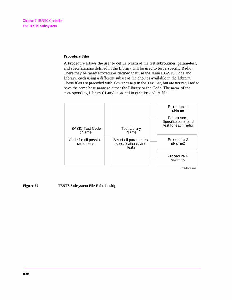
Chapter 7, IBASIC ControllerThe TESTS Subsystem
Procedure Files
A Procedure allows the user to define which of the test subroutines, parameters, and specifications defined in the Library will be used to test a specific Radio. There may be many Procedures defined that use the same IBASIC Code and Library, each using a different subset of the choices available in the Library. These files are preceded with alower case p in the Test Set, but are not required to have the same base name as either the Library or the Code. The name of the corresponding Library (if any) is stored in each Procedure file.
Figure 29 TESTS Subsystem File Relationship
IBASIC Test CodecName
Code for all possibleradio tests
Test LibrarylName
Set of all parameters,specifications, and
tests
Procedure 1pName
Parameters,Specifications, andtest for each radio
Procedure 2pName2
Procedure NpNameN
ch6drw06.drw
438
Chapter 7, IBASIC ControllerThe TESTS Subsystem
TESTS Subsystem Screens
The TESTS Subsystem uses several screens to create, select, and copy files, and to run tests.
The Main TESTS Subsystem Screen
Refer to figure 30 .
The TESTS (Main Menu) screen is accessed by pressing the front panel TESTS key. Test procedures are selected and run from this screen. Additionally, access to all other TESTS Subsystem screens is accomplished from this screen.
The Select Procedure Location: field is used to select the mass storage location for the procedure to be loaded. The Select Procedure Filename: field is used to select the name of the procedure to be loaded. The Description: field gives the user a brief description of the procedure currently selected in the Select Procedure Filename: field.
To view all the Procedures available on the mass storage location currently selected in the Select Procedure Location: field, position the cursor on the Select Procedure Filename: field and push the rotary knob. A menu will appear in the lower right corner of the screen, displaying all the procedure files which are available. This is not a listing of the full contents of the selected mass storage location, it is only a list of the procedures files that are stored on that media.
439
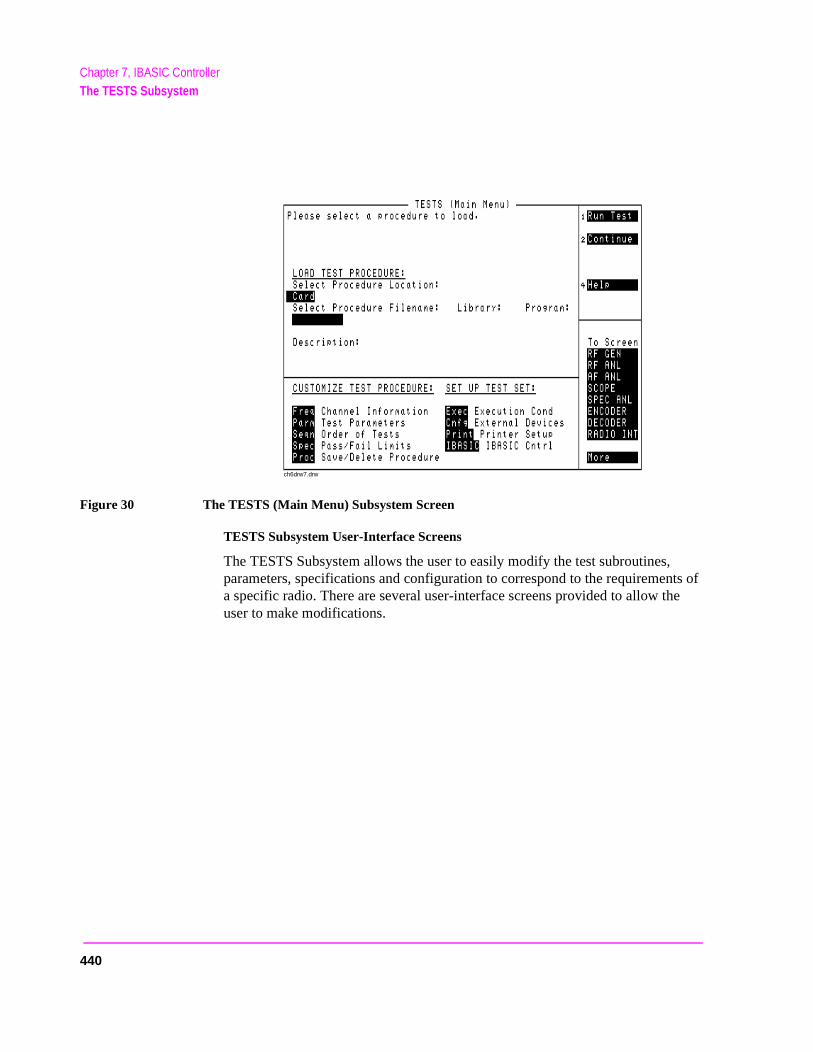
Chapter 7, IBASIC ControllerThe TESTS Subsystem
Figure 30 The TESTS (Main Menu) Subsystem Screen
TESTS Subsystem User-Interface Screens
The TESTS Subsystem allows the user to easily modify the test subroutines, parameters, specifications and configuration to correspond to the requirements of a specific radio. There are several user-interface screens provided to allow the user to make modifications.
ch6drw7.drw
440

Chapter 7, IBASIC ControllerThe TESTS Subsystem
f
for
s to r
nd
To access any of these screens, position the cursor on the desired field and push the rotary knob.
• The Order of Tests screen lets the user select the desired test(s) from the full set oavailable tests in the loaded procedure file.
• The Channel Information screen defines the transmit and receive frequencies usedthe selected tests.
• The Pass/Fail Limits screen defines the specifications used to generate pass/fail messages during testing.
• The Test Parameters screen is used to define instrument settings and characteristicmatch those of the radio being tested (audio load impedance, audio power, powesupply voltage).
• The External Devices screen identifies all connected HP-IB equipped instruments atheir HP-IB addresses.
• The Save/Delete Procedure screen is used to save or delete Procedures.
• The Printer Setup screen is used to select the printer used for IBASIC PRINT commands and to configure the format of the printer page.
• The Execution Cond screen is used to configure the IBASIC program execution conditions.
• The IBASIC Cntrl screen is the IBASIC Controllers display screen.
Refer to the TESTS screen descriptions in the Test Set User’s Guide for information concerning how the different TESTS Subsystem screens are used.
The use of the IBASIC Controller screen is described in the beginning of this chapter.
441

Chapter 7, IBASIC ControllerThe TESTS Subsystem
442
8
sing r to
Programming The Call Processing Subsystem
This chapter presents information on how to control the Test Set’s Call ProcesSubsystem using the Call Processing Subsystem’s remote user interface. Foinformation on how to control the Call Processing Subsystem manually, referChapter 6, Call Processing Subsystem, in the Test Set’s User’s Guide. It is highly recommended that the programmer be familiar with using the Call Processing Subsystem manually before reading this chapter.
443
Chapter 8, Programming The Call Processing SubsystemDescription of the Call Processing Subsystem’s Remote User Interface
wing
l
all
ut
ich n). he
ceiver the of a
s; bile
Description of the Call Processing Subsystem’s Remote User Interface
The Call Processing Subsystem’s Remote User Interface consists of the folloitems:
• a set of programming commands which access all available fields on the five CalProcessing Subsystem screens
• a status register group whose condition register reflects the current state of the CProcessing Subsystem annunciator state indicators
• a set of error messages, available through HP-IB, which provide information aboerror conditions encountered while in the Call Processing Subsystem
The programming commands provide the capability to generate control programs whcan establish a cellular link between the Test Set and a cellular phone (mobile statioThe status register group and the error messages provide the control program with tinformation necessary to make program flow decisions.
Once a link is established the control program can exercise the call processing functionality of the mobile station, such as:
• the decoding of orders from the Base Station, such as; orders to retune the transto a new frequency, to alert the mobile station user to an incoming call, to adjust transceiver output power level, or to release the mobile station upon completion call.
• the encoding of signaling information for transmission to the base station, such adialed digits for call origination, disconnect signal at the completion of a call, or moidentification number.
444

Chapter 8, Programming The Call Processing SubsystemDescription of the Call Processing Subsystem’s Remote User Interface
arrier
e voice llow
e built ontrol e bit m the
o the nitor
In addition to the mobile station’s call processing functions, the control program can utilize the RF and audio instruments in the Test Set to characterize the overall performance of the mobile station while on an active voice channel by making such measurements as; receiver sensitivity, FM Hum & Noise, transmitter carrier power, cfrequency accuracy, or SAT tone deviation.
The Call Processing Subsystem decodes various reverse control channel and reverschannel signaling messages. The remote user interface provides commands which athe control program access to the contents of the decoded messages.
For forward control channel and forward voice channel signaling messages, the CallProcessing Subsystem provides the option of sending messages whose contents arusing the rules and regulations specified in the applicable industry standard, or the cprogram can define the message contents as desired. Having the capability to set thpatterns of the signaling messages sent to the mobile station gives the control progracapability to test the robustness of the mobile station by introducing known errors intsignaling messages. Once an error has been introduced the control program can mothe response of the mobile station.
445

Chapter 8, Programming The Call Processing SubsystemDescription of the Call Processing Subsystem’s Remote User Interface
e
d as est the ation res
voice iver
hile ile
ically
ator . and
Operational Overview
The Test Set simulates a cellular base station by using its hardware and firmware resources to initiate and maintain a link with a mobile station. Unlike a real base station, the Test Set has only one transceiver (its signal generator and RF/AF analyzer) and can support only one mobile station at a time. This means that the Test Set’s transceiver can be configured as either a control channel or a voicchannel, but not both simultaneously.
To establish a link with a mobile station the Test Set’s transceiver is configurea control channel. Once a link has been established and the user wishes to tmobile station on a voice channel, the Test Set sends the appropriate informto the mobile station on the control channel and then automatically re-configuits transceiver to the voice channel assigned to the mobile station. Once the channel link is terminated, the Test Set automatically re-configures its transceback to being a control channel.
Handoffs are accomplished in a similar manner. When a handoff is initiated won a voice channel, the Test Set sends the necessary information to the mobstation on the current voice channel. At the proper time, the Test Set automatre-configures its transceiver to the new voice channel.
Figure 31, "Call Processing State Diagram," on page 447 illustrates the primary call processing functions available in the Call Processing Subsystem. Each box represents a call processing state and includes the measurement informationavailable while in that state. Each box also includes the name of the annuncion the call processing screen that will be lit while in that call processing stateEvents which trigger transitions between the various states are shown on thediagram. Events which are initiated from the Test Set are shown in solid linesevents which are initiated from the mobile station are shown in dashed lines.
446
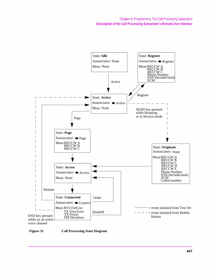
Chapter 8, Programming The Call Processing SubsystemDescription of the Call Processing Subsystem’s Remote User Interface
Figure 31 Call Processing State Diagram
State: Active
Meas: None
Annunciator: Active
Active
State: Idle
Meas: None
Annunciator: None
State: Register
Meas:RECCW A
Annunciator: Register
Phone NumberESN (hexadecimal)
Register
END key pressedwhile on an activevoice channel
State: Originate
SEND key pressedwhile Roamingor in Service mode
State: Page
Annunciator: PageMeas:RECCW A
RECCW BRECCW C
Page
State: Access
Meas: None
Annunciator: Access
State: Connected
Meas:RVCOrdCon
Annunciator: Connect
TX Freq ErrorTX PowerFM Deviation
Meas:RECCW ARECCW BRECCW CRECCW DRECCW E
Release
Handoff
Phone NumberESN (hexadecimal)SCMCalled number
RECCW BRECCW C
SCM
Annunciator: None
Order
= event initiated from Test Set
= event initiated from Mobile Station
447
Chapter 8, Programming The Call Processing SubsystemUsing the Call Processing Subsystem’s Remote User Interface
obile
need ut
t) is to
Using the Call Processing Subsystem’s Remote User Interface
In order to use the Call Processing Subsystem’s Remote User Interface, a mstation must be powered on, and connected to the Test Set.
Connecting a Mobile Station
Figure 32, "Connecting a Mobile Station to the Test Set," on page 449 shows a typical example of how to connect a mobile station to the Test Set. You may a special fixture to access the mobile station’s antenna, audio in, and audio osignals. These fixtures are available from the mobile station’s manufacturer.
If any audio testing is to be done on the mobile station, the audio input (microphone input) to the mobile station and the audio output (speaker outpufrom the mobile station must be connected to the Test Set. If no audio testingbe done only the antenna needs to be connected to the Test Set.
448
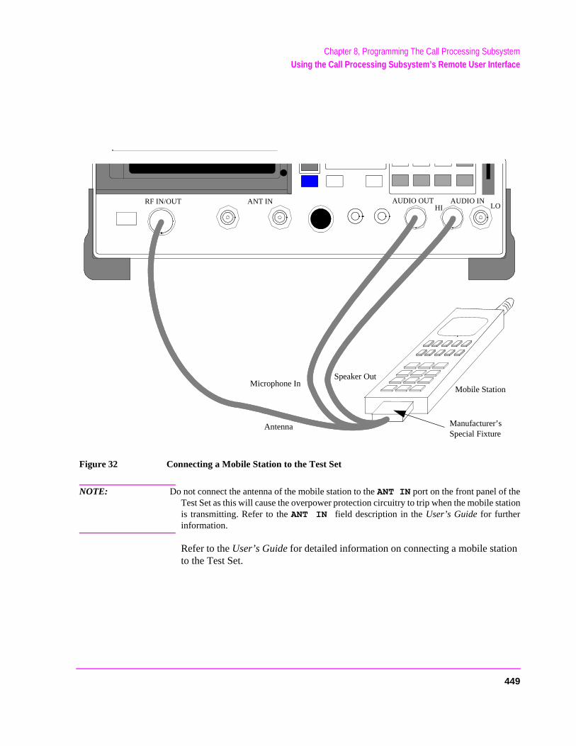
Chapter 8, Programming The Call Processing SubsystemUsing the Call Processing Subsystem’s Remote User Interface
Figure 32 Connecting a Mobile Station to the Test Set
NOTE: Do not connect the antenna of the mobile station to the ANT IN port on the front panel of theTest Set as this will cause the overpower protection circuitry to trip when the mobile stationis transmitting. Refer to the ANT IN field description in the User’s Guide for furtherinformation.
Refer to the User’s Guide for detailed information on connecting a mobile station to the Test Set.
ANT IN
Manufacturer’s Special Fixture
AUDIO OUTRF IN/OUT AUDIO INLOHI
Antenna
Speaker OutMicrophone In
Mobile Station
449
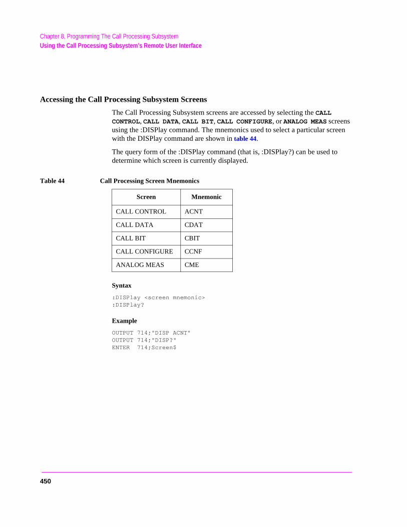
Chapter 8, Programming The Call Processing SubsystemUsing the Call Processing Subsystem’s Remote User Interface
Accessing the Call Processing Subsystem Screens
The Call Processing Subsystem screens are accessed by selecting the CALL CONTROL, CALL DATA, CALL BIT, CALL CONFIGURE, or ANALOG MEAS screens using the :DISPlay command. The mnemonics used to select a particular screen with the DISPlay command are shown in table 44.
The query form of the :DISPlay command (that is, :DISPlay?) can be used to determine which screen is currently displayed.
Syntax
:DISPlay <screen mnemonic>:DISPlay?
Example
OUTPUT 714;"DISP ACNT"OUTPUT 714;"DISP?"ENTER 714;Screen$
Table 44 Call Processing Screen Mnemonics
Screen Mnemonic
CALL CONTROL ACNT
CALL DATA CDAT
CALL BIT CBIT
CALL CONFIGURE CCNF
ANALOG MEAS CME
450
Chapter 8, Programming The Call Processing SubsystemUsing the Call Processing Subsystem’s Remote User Interface
ing
Command Syntax
The Call Processing Subsystem programming commands and command syntax are detailed in "Call Processing" on page 126. Refer to the “Programming the (screen name) Screen” sections in this chapter for detailed information on usthe Call Processing Subsystem programming commands for each screen.
CAUTION: The *OPC, *OPC? and *WAI commands should not be used for determining if a CallProcessing Subsystem state command has completed successfully. Call ProcessingSubsystem states do not complete, a state is either active or not active. Using the *OPC,*OPC? or *WAI commands with a Call Processing Subsystem state command results in adeadlock condition. Refer to the *OPC, *OPC? and *WAI commands in section"Common Command Descriptions" on page 213 for descriptions of the deadlockconditions.
The *OPC, *OPC? or *WAI commands should not be used with any of the following CallProcessing Subsystem commands: :ACTive, :REGister, :PAGE, :HANDoff, :RELease.
The Call Processing Subsystem Status Register Group should be used to controlprogram flow. Refer to "Using the Call Processing Status Register Group ToControl Program Flow" on page 454 for further information.
451
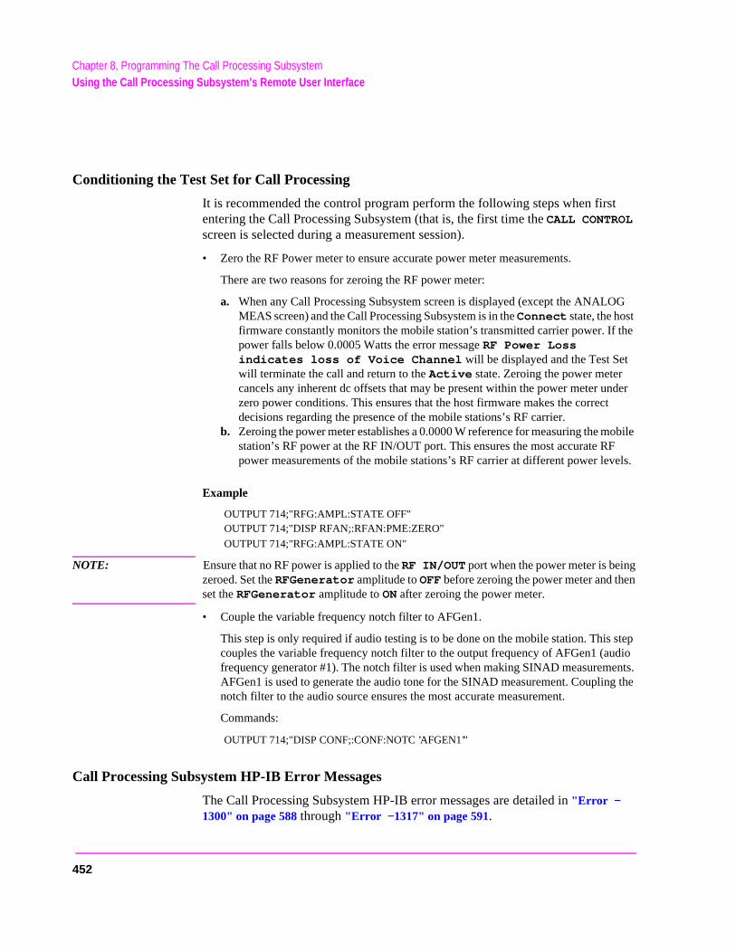
Chapter 8, Programming The Call Processing SubsystemUsing the Call Processing Subsystem’s Remote User Interface
G
the
nder
obile els.
gn
step dio ents. g the
Conditioning the Test Set for Call Processing
It is recommended the control program perform the following steps when first entering the Call Processing Subsystem (that is, the first time the CALL CONTROL screen is selected during a measurement session).
• Zero the RF Power meter to ensure accurate power meter measurements.
There are two reasons for zeroing the RF power meter:
a. When any Call Processing Subsystem screen is displayed (except the ANALOMEAS screen) and the Call Processing Subsystem is in the Connect state, the host firmware constantly monitors the mobile station’s transmitted carrier power. If power falls below 0.0005 Watts the error message RF Power Loss indicates loss of Voice Channel will be displayed and the Test Set will terminate the call and return to the Active state. Zeroing the power meter cancels any inherent dc offsets that may be present within the power meter uzero power conditions. This ensures that the host firmware makes the correctdecisions regarding the presence of the mobile stations’s RF carrier.
b. Zeroing the power meter establishes a 0.0000 W reference for measuring the mstation’s RF power at the RF IN/OUT port. This ensures the most accurate RFpower measurements of the mobile stations’s RF carrier at different power lev
Example
OUTPUT 714;"RFG:AMPL:STATE OFF"OUTPUT 714;"DISP RFAN;:RFAN:PME:ZERO"
OUTPUT 714;"RFG:AMPL:STATE ON"
NOTE: Ensure that no RF power is applied to the RF IN/OUT port when the power meter is beinzeroed. Set the RFGenerator amplitude to OFF before zeroing the power meter and theset the RFGenerator amplitude to ON after zeroing the power meter.
• Couple the variable frequency notch filter to AFGen1.
This step is only required if audio testing is to be done on the mobile station. Thiscouples the variable frequency notch filter to the output frequency of AFGen1 (aufrequency generator #1). The notch filter is used when making SINAD measuremAFGen1 is used to generate the audio tone for the SINAD measurement. Couplinnotch filter to the audio source ensures the most accurate measurement.
Commands:
OUTPUT 714;"DISP CONF;:CONF:NOTC ’AFGEN1’"
Call Processing Subsystem HP-IB Error Messages
The Call Processing Subsystem HP-IB error messages are detailed in "Error −1300" on page 588 through "Error −1317" on page 591.
452
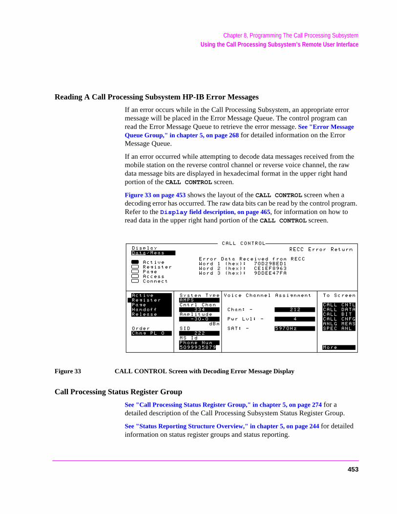
Chapter 8, Programming The Call Processing SubsystemUsing the Call Processing Subsystem’s Remote User Interface
Reading A Call Processing Subsystem HP-IB Error Messages
If an error occurs while in the Call Processing Subsystem, an appropriate error message will be placed in the Error Message Queue. The control program can read the Error Message Queue to retrieve the error message. See "Error Message Queue Group," in chapter 5, on page 268 for detailed information on the Error Message Queue.
If an error occurred while attempting to decode data messages received from the mobile station on the reverse control channel or reverse voice channel, the raw data message bits are displayed in hexadecimal format in the upper right hand portion of the CALL CONTROL screen.
Figure 33 on page 453 shows the layout of the CALL CONTROL screen when a decoding error has occurred. The raw data bits can be read by the control program. Refer to the Display field description, on page 465, for information on how to read data in the upper right hand portion of the CALL CONTROL screen.
Figure 33 CALL CONTROL Screen with Decoding Error Message Display
Call Processing Status Register Group
See "Call Processing Status Register Group," in chapter 5, on page 274 for a detailed description of the Call Processing Subsystem Status Register Group.
See "Status Reporting Structure Overview," in chapter 5, on page 244 for detailed information on status register groups and status reporting.
453

Chapter 8, Programming The Call Processing SubsystemUsing the Call Processing Subsystem’s Remote User Interface
to
the roup
g perly
Using the Call Processing Status Register Group To Control Program Flow
The Call Processing Subsystem uses annunciators to indicate its current state. That is, if the Call Processing Subsystem is in the connected state, the Connect annunciator will be lit.
Bits 0 through 5 of the Condition register in the Call Processing Status Register Group mirror the condition of the annunciators. That is, if the Connect annunciator is lit, bit 5 of the Condition register will be TRUE, logic 1, and all other bits will be FALSE, logic 0.
Under most circumstances a control program will need some means of determining the state of an interaction between the control program, the Call Processing Subsystem and the mobile station.
For example, if the control program wishes to register a mobile station, the control program will have to send a command to put the Call Processing subsystem into the Active state, then, once in the Active state, send a registration message by putting the Call Processing Subsystem into the Register state and then determine when to read the mobile station’s registration information in order make a determination as to whether the mobile station registered correctly.
In the manual user interface, the annunciators supply this state information tooperator. In the remote user interface, the Call Processing Status Register Gsupplies the state information to the control program.
The control program can access this information in one of two ways; by pollinthe status registers or by using the service request feature of the HP-IB. If proimplemented, either method can be used to obtain the information.
454

Chapter 8, Programming The Call Processing SubsystemUsing the Call Processing Subsystem’s Remote User Interface
Advantages/Disadvantages of Polling
Polling has the advantage that the control program can react quicker to the change in state since the control program does not have to execute the code necessary to determine what condition caused the service request line to be asserted.
Polling has the disadvantage that, if improperly implemented, it can prevent the Call Processing Subsystem from properly interfacing with the mobile station.
The Test Set has a multitasking architecture wherein multiple processes execute on a priority driven and event driven basis. One of the highest priority processes is the process that services the HP-IB.
If a control program constantly polls the status registers to determine when a particular state is true, that state may take a very long time to go true or it may never go to the true state. This is because the process which would cause that state to go true will take a long time to complete or never complete because it is constantly being interrupted by the HP-IB service process.
This condition may cause problems with the timing of the message protocol between the Test Set and the mobile station. Therefore, care must be exercised when using the polling technique to allow enough time between polls for processes to execute within the Test Set.
Some computer systems and/or programming languages may not support the service request feature of the HP-IB and consequently polling would be the only technique available to the programmer. When using a polling technique be sure to include a delay in the polling loop.
Advantages/Disadvantages of Using Service Request
The service request feature of the HP-IB has the advantage that it allows the Call Processing Subsystem to execute at its maximum speed since processes within the subsystem are not being constantly interrupted by the need to service the HP-IB.
The service request feature of the HP-IB has the disadvantage that it takes more code to implement within the control program. The consequence of which is a slight reduction in the overall throughput of the control program since more code must be executed to accomplish the same task.
See "Setting Up and Enabling SRQ Interrupts," in chapter 5, on page 296 for information on using the service request method.
The choice of which technique to use, polling or service request, will depend upon the needs of the particular application.
455
Chapter 8, Programming The Call Processing SubsystemUsing the Call Processing Subsystem’s Remote User Interface
When To Query Data Messages Received From The Mobile Station
The Call Processing Subsystem makes available to the control program many data messages received from the mobile station. For example, if the Test Set sends a registration message to the mobile station, the registration information (MIN, ESN, SCM) received from the mobile station can be read by the control program.
The data messages are displayed on the CRT after the successful completion of the call processing function (registration, page, origination, etc.). When call processing functions complete, state changes occur within the Call Processing Subsystem. For example, when a registration completes the Call Processing Subsystem exits the register state (the Register annunciator is turned off) and returns to the active state (the Active annunciator is turned on).
The control program should only query the Test Set for the data messages after all the state transitions are complete. For example, the control program should not attempt to read the MIN, ESN or SCM until after the Register annunciator is turned off and the Active annunciator is turned on.
This is because the Test Set has a multitasking architecture wherein multiple processes execute on a priority driven and an event driven basis. Each process is given a timeslice on the CPU depending upon its priority, the priority of other processes and the nature of the events occurring within the Test Set.
Upon completion, processes within the Call Processing Subsystem pass data messages received from the mobile station to the Measurement Display Process which displays the information on the CRT during its next CPU timeslice. If the control program attempts to query the data fields before the Measurement Display Process has posted the information to the CRT, it is possible that the fields will be blank or contain data from a previous call processing function.
Waiting to read the data messages until after all state transitions have occurred ensures that the data from the most recent call processing function will have been posted. Table 45, "Call Processing Subsystem State Transitions" on page 457 lists the possible state transitions within the Call Processing Subsystem.
456
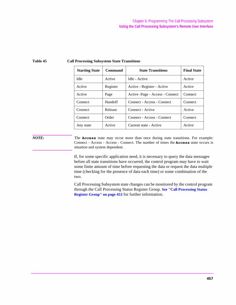
Chapter 8, Programming The Call Processing SubsystemUsing the Call Processing Subsystem’s Remote User Interface
NOTE: The Access state may occur more than once during state transitions. For example:Connect - Access - Access - Connect. The number of times the Access state occurs issituation and system dependent.
If, for some specific application need, it is necessary to query the data messages before all state transitions have occurred, the control program may have to wait some finite amount of time before requesting the data or request the data multiple time (checking for the presence of data each time) or some combination of the two.
Call Processing Subsystem state changes can be monitored by the control program through the Call Processing Status Register Group. See "Call Processing Status Register Group" on page 453 for further information.
Table 45 Call Processing Subsystem State Transitions
Starting State Command State Transitions Final State
Idle Active Idle - Active Active
Active Register Active - Register - Active Active
Active Page Active -Page - Access - Connect Connect
Connect Handoff Connect - Access - Connect Connect
Connect Release Connect - Active Active
Connect Order Connect - Access - Connect Connect
Any state Active Current state - Active Active
457
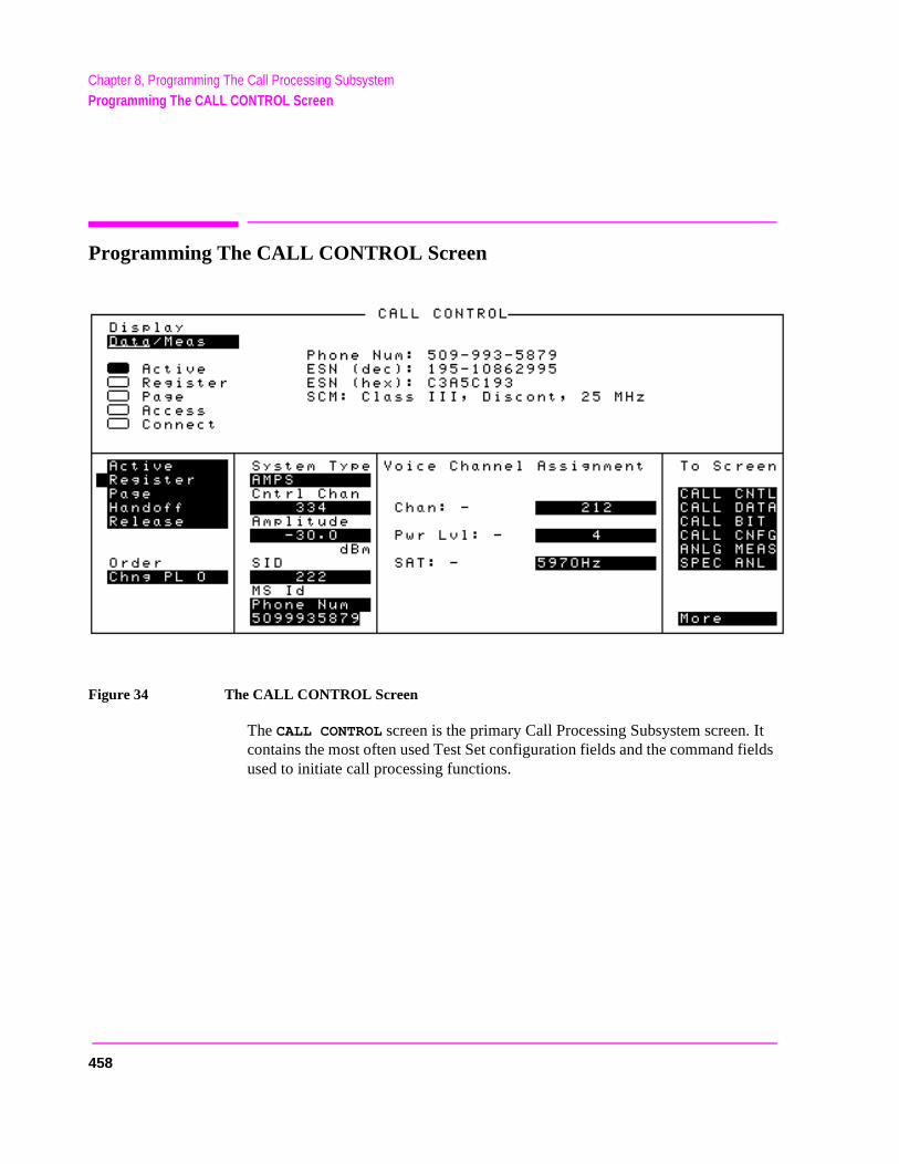
Chapter 8, Programming The Call Processing SubsystemProgramming The CALL CONTROL Screen
Programming The CALL CONTROL Screen
Figure 34 The CALL CONTROL Screen
The CALL CONTROL screen is the primary Call Processing Subsystem screen. It contains the most often used Test Set configuration fields and the command fields used to initiate call processing functions.
458
Chapter 8, Programming The Call Processing SubsystemProgramming The CALL CONTROL Screen
o s
orce
[] Access
When lit, the Access annunciator indicates that the Test Set is signaling the mobile station with command information on the forward voice channel. This is a transitory state.
The Access annunciator is not programmable.
The state of the Access annunciator is reflected in the Call Processing Status Register Group Condition Register bit 4. See “Status Reporting” in the User’sGuide for further information.
The Test Set’s speaker is turned off when in the Access state. This is done teliminate any possible audio feedback which may occur if the mobile station’microphone is open.
Active
This field is used to turn on the forward control channel of the Test Set or to fa return to the Active state from any other state (Register, Page, Access, Connect).
If the forward control channel of the Test Set is already active, sending the :ACTive command will deactivate and then reactivate the control channel.
The :ACTive command is used to control this field.
There is no query form of the :ACTive command.
Syntax
:ACTive
Example
OUTPUT 714;"CALLP:ACT"
459
Chapter 8, Programming The Call Processing SubsystemProgramming The CALL CONTROL Screen
hen
[] Active
When lit, the Active annunciator indicates that the control channel of the Test Set is turned on.
If this annunciator is lit, the Base Station is transmitting system parameter overhead messages on the assigned control channel. If the annunciator is not lit the base station is not active (note that the Test Set may still be outputting a modulated RF carrier but the Test Set’s firmware is not active and no communication can occur between a mobile station and the Test Set).
The Active annunciator is not programmable.
The state of the Active annunciator is reflected in the Call Processing Status Register Group Condition Register bit 0. See “Status Reporting” in the User’sGuide for further information.
AF Freq
The AF Freq field is displayed only when the Display field is set to Meas.
This field displays the audio frequency of the demodulated FM signal being transmitted by the mobile station. Four dashes (----) indicate that no audio frequency is present to measure. A numeric value would only be displayed wthe Test Set’s Connected annunciator is lit.
Refer to the Display field description, on page 465, for information on how to read measurement results from this field.
460
Chapter 8, Programming The Call Processing SubsystemProgramming The CALL CONTROL Screen
, the
tion .
bile
the
n a
Amplitude
This field is used to set the output power of the Test Set’s transmitter (that isoutput power of the Test Set’s RF Generator).
The :AMPLitude command is used to control this field.
Refer to the “Real Number Setting Syntax” section of the for detailed informaon the various parameters which can be used with the :AMPLitude command
To query the current setting of the amplitude field use the :AMPLitude? command.
Syntax
:AMPLitude <real number> <units>:AMPlitude?
Example
OUTPUT 714;"CALLP:AMPL -50 DBM"OUTPUT 714;"CALLP:AMPL?"ENTER 714;Ampl_val$
Called Number:
This information string displays the called phone number, in decimal form, received from the mobile station on the reverse control channel when the mostation originates a call. The Called Number: field is only displayed when the Display field is set to Data and a reverse control channel message has beendecoded when the mobile originates a call.
Refer to the Display field description, on page 465, for information on how to read data displayed in the upper right hand portion of the CALL CONTROL screen.
Chan:
The Chan: is divided into two fields:
• The left-hand field displays the voice channel number assignment being used byTest Set and the mobile station.
A numeric value is only displayed when the Test Set’s Connected annunciator is lit (connected state). A “-” is displayed if a mobile station is not actively connected ovoice channel.
This is a read only field.
461
Chapter 8, Programming The Call Processing SubsystemProgramming The CALL CONTROL Screen
ich nnel
the
The :AVCNumber? query command is used to query the contents of the left-hand field.
There is no command form of the :AVCNumber? query.
Syntax
:AVCNumber?
Example
OUTPUT 714;"CALLP:AVCN?"
ENTER 714;Active_vc_number$
• The right-hand field (highlighted field) is used to set the voice channel number whwill be assigned to the mobile station by the Test Set as either an initial voice chaassignment or as a handoff voice channel assignment.
The :VCHannel command is used to control the right-hand subfield.
The query form of the command (that is, :VCHannle?) can be used to determine current voice channel setting.
Syntax
:VCHannel <real number>
:VCHannel?
Example
OUTPUT 714;"CALLP:VCH 215"OUTPUT 714;"CALLP:VCH?"
ENTER 714;Vch_number$
Cntl Channel
This field is used to set the control channel number used by the Test Set.
The :CCHannel command is used to control this field.
The Cntl Channel field is an immediate action field. That is, whenever the :CCHannel command is sent, the change is reflected immediately in the physical configuration of the Test Set (the control channel is immediately deactivated, reconfigured, and then reactivated to reflect the change) and causes an immediate change to the current state of the Call Processing Subsystem (the state is set to Active).
462
Chapter 8, Programming The Call Processing SubsystemProgramming The CALL CONTROL Screen
NOTE: If the Test Set is in the Connect state and a change is made to the Cntl Channel fieldthe Connect state will be lost.
The query form of the command (that is, :CCHannel?) can be used to determine the current control channel setting.
Syntax
:CCHannel <integer number>:CCHannel?
Example
OUTPUT 714;"CALLP:CCH 333"OUTPUT 714;"CALLP:CCH?"ENTER 714;Control_chan
463
Chapter 8, Programming The Call Processing SubsystemProgramming The CALL CONTROL Screen
ittedl and on
[] Connect
When lit, the Connect annunciator indicates that the mobile station is connected to the Test Set on a voice channel.
The Connect annunciator is not programmable.
The state of the Connect annunciator is reflected in the Call Processing Status Register Group Condition Register bit 5. See “Status Reporting” in the Application Guide for further information.
NOTE: When the CALL CONTROL screen is displayed and the Call Processing Subsystem is in theConnect state, the host firmware constantly monitors the mobile station’s transmcarrier power. If the power falls below 0.0005Watts the Test Set will terminate the calreturn to the Active state. The mobile station’s transmitted carrier power is monitoredall Call Processing Subsystem screens except the ANALOG MEAS screen.
464
Chapter 8, Programming The Call Processing SubsystemProgramming The CALL CONTROL Screen
hannel ts
on a
Display
The top right-hand portion of the CALL CONTROL screen is used to display:
• Decoded data messages received from the mobile station on the reverse control cor the reverse voice channel. If a decoding error occurs the raw data message bireceived from the mobile station are displayed in hexadecimal format.
• Modulation quality measurements made on the mobile station’s RF carrier while voice channel.
The Display field is used to select the type of mobile station information to be displayed.
The :MODE command is used to control the Display field for AMPS, TACS, and JTACS system types.
The query form of the command (that is, :MODE?) can be used to determine the current setting of the Display field while AMPS, TACS, and JTACS system type is selected.
Syntax
:MODE <’><DATA/MEAS><’>:MODE?
Example
OUTPUT 714;"CALLP:MODE ’DATA’"OUTPUT 714;"CALLP:MODE?"ENTER 714;Screen$
Setting the Display field to Data
When the Display field is set to Data the top right-hand portion of the CALL CONTROL screen is used to display decoded data message(s) received from the mobile station on the reverse control channel or the reverse voice channel.
If the data message(s) received from the mobile station can be correctly decoded, the decoded message contents are displayed. Figure 34, "The CALL CONTROL Screen," on page 458 shows an example of a correctly decoded reverse control channel data message being displayed in the top right-hand portion of the screen.
If the data message(s) cannot be correctly decoded, the raw data message bits are displayed in hexadecimal format. Figure 33, "CALL CONTROL Screen with Decoding Error Message Display," on page 453 shows an example of the raw data message bits being displayed in hexadecimal format in the top right-hand portion of the screen when a decoding error has occurred
465
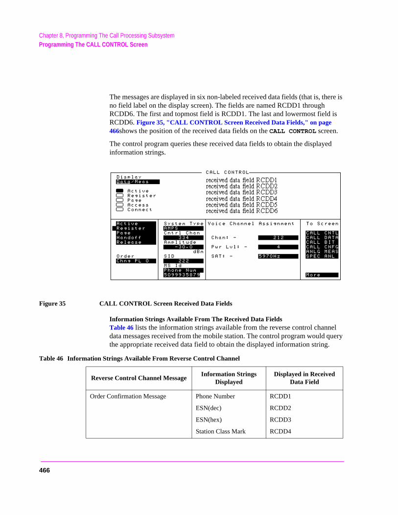
Chapter 8, Programming The Call Processing SubsystemProgramming The CALL CONTROL Screen
The messages are displayed in six non-labeled received data fields (that is, there is no field label on the display screen). The fields are named RCDD1 through RCDD6. The first and topmost field is RCDD1. The last and lowermost field is RCDD6. Figure 35, "CALL CONTROL Screen Received Data Fields," on page 466shows the position of the received data fields on the CALL CONTROL screen.
The control program queries these received data fields to obtain the displayed information strings.
Figure 35 CALL CONTROL Screen Received Data Fields
Information Strings Available From The Received Data Fields Table 46 lists the information strings available from the reverse control channel data messages received from the mobile station. The control program would query the appropriate received data field to obtain the displayed information string.
Table 46 Information Strings Available From Reverse Control Channel
Reverse Control Channel MessageInformation Strings
DisplayedDisplayed in Received
Data Field
Order Confirmation Message Phone Number
ESN(dec)
ESN(hex)
Station Class Mark
RCDD1
RCDD2
RCDD3
RCDD4
466
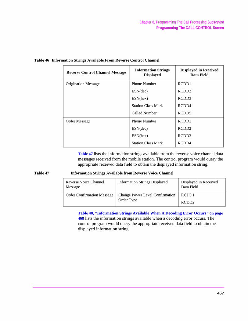
Chapter 8, Programming The Call Processing SubsystemProgramming The CALL CONTROL Screen
Table 47 lists the information strings available from the reverse voice channel data messages received from the mobile station. The control program would query the appropriate received data field to obtain the displayed information string.
Table 48, "Information Strings Available When A Decoding Error Occurs" on page 468 lists the information strings available when a decoding error occurs. The control program would query the appropriate received data field to obtain the displayed information string.
Origination Message Phone Number
ESN(dec)
ESN(hex)
Station Class Mark
Called Number
RCDD1
RCDD2
RCDD3
RCDD4
RCDD5
Order Message Phone Number
ESN(dec)
ESN(hex)
Station Class Mark
RCDD1
RCDD2
RCDD3
RCDD4
Table 46 Information Strings Available From Reverse Control Channel
Reverse Control Channel MessageInformation Strings
DisplayedDisplayed in Received
Data Field
Table 47 Information Strings Available from Reverse Voice Channel
Reverse Voice Channel Message
Information Strings Displayed Displayed in Received Data Field
Order Confirmation Message Change Power Level ConfirmationOrder Type
RCDD1
RCDD2
467
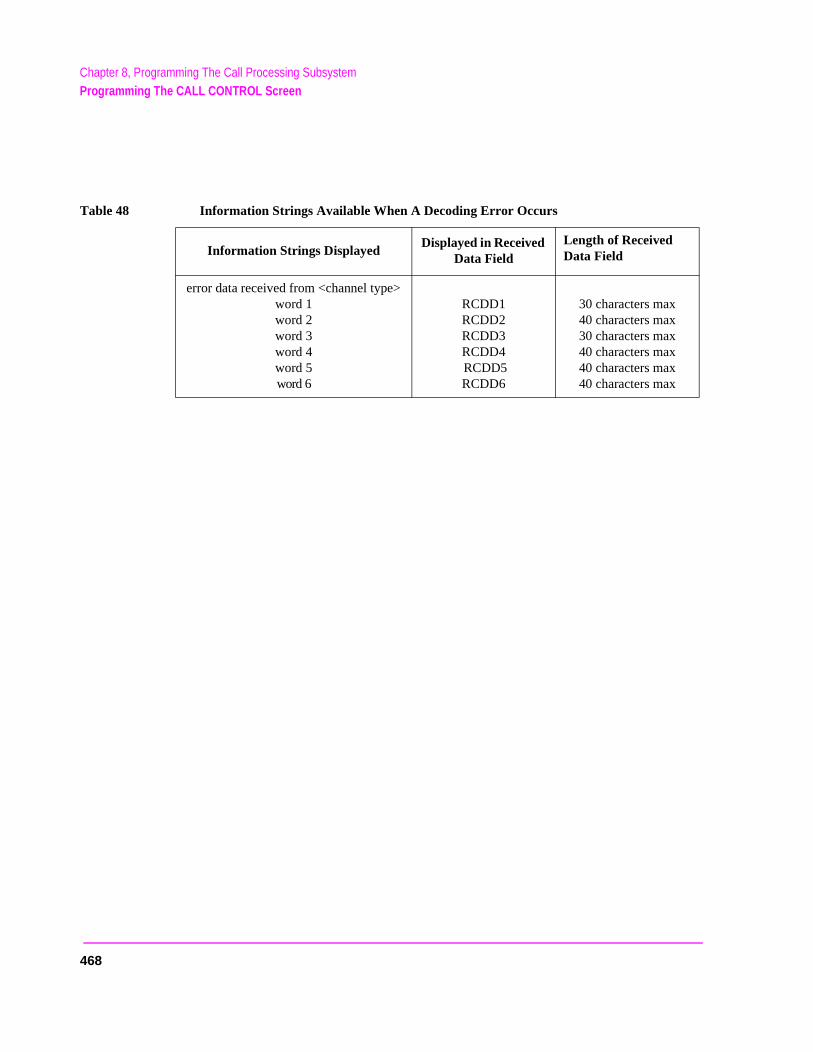
Chapter 8, Programming The Call Processing SubsystemProgramming The CALL CONTROL Screen
Table 48 Information Strings Available When A Decoding Error Occurs
Information Strings DisplayedDisplayed in Received
Data FieldLength of Received Data Field
error data received from <channel type>word 1word 2word 3word 4word 5word 6
RCDD1RCDD2RCDD3RCDD4 RCDD5RCDD6
30 characters max40 characters max30 characters max40 characters max40 characters max40 characters max
468

Chapter 8, Programming The Call Processing SubsystemProgramming The CALL CONTROL Screen
ents
n the
r,
Reading The Received Data Fields To read the decoded data messages received from the mobile station on the reverse control channel or reverse voice channel or the raw data message bits displayed when a decoding error occurs, the control program queries one, some, or all of the six received data fields. The information in each field is returned exactly as displayed on the CRT. The information is returned to the control program as a quoted string (“This is an example.”).
The received data fields are read only data fields.
The :RCDD1? through :RCDD6? query commands are used to read the contof the six received data fields.
Syntax
:RCDD<1-6>?
Example
OUTPUT 714;"CALLP:RCDD1?"ENTER 714;Rcv_data$
Setting the Display Field to Meas
When the Display field is set to Meas the top right-hand portion of the CALL CONTROL screen is used to display modulation quality measurements made omobile station’s RF carrier while on a voice channel.
Four characteristics of the RF carrier are measured: TX Freq Error, TX PoweFM Deviation, and AF Frequency. The Meas information is only available in the connected state (that is, the Connect annunciator is lit).
Figure 36, "CALL CONTROL Screen with Meas Selected," on page 470 shows the layout of the CALL CONTROL screen when Meas is selected.
469
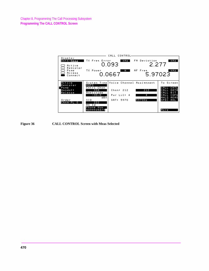
Chapter 8, Programming The Call Processing SubsystemProgramming The CALL CONTROL Screen
Figure 36 CALL CONTROL Screen with Meas Selected
470
Chapter 8, Programming The Call Processing SubsystemProgramming The CALL CONTROL Screen
a
al onse
Reading The Modulation Quality Measurement Fields The MEAS selection brings some of the Test Set’s Audio Analyzer fields and some of the Test Set’s RF Analyzer fields onto the CALL CONTROL screen for the purpose of making modulation quality measurements on the mobile station’s RF carrier while onvoice channel.
The measurement results contained in these fields are accessed using the :MEASure command. See "Measure," in chapter , on page 151 for detailed command syntax.
Syntax
See "Measure," in chapter , on page 151
Example
OUTPUT 714;"MEAS:RFR:POW?"ENTER 714;Tx_power OUTPUT 714;"MEAS:RFR:FREQ:ERR?"ENTER 714;Tx_freq_error OUTPUT 714;"MEAS:AFR:FREQ?"ENTER 714;Af_freq OUTPUT 714;"MEAS:AFR:FM?"ENTER 714;Fm_deviation
ESN (dec):
This information string contains the electronic serial number (ESN), in decimform, received from the mobile station on the reverse control channel in respto a forward control channel message.
The ESN (dec): field is only displayed when the Display field is set to Data and a reverse control channel message containing this information has beendecoded.
Refer to the Display field description, on page 465, for information on how to read data displayed in the upper right hand portion of the CALL CONTROL screen.
471
Chapter 8, Programming The Call Processing SubsystemProgramming The CALL CONTROL Screen
ESN (hex):
This information string displays the electronic serial number (ESN), in hexadecimal form, received from the mobile station on the reverse control channel in response to a forward control channel message.
The ESN (hex): field is only displayed when the Display field is set to Data and a reverse control channel message containing this information has been decoded.
Refer to the Display field description, on page 465, for information on how to read data displayed in the upper right hand portion of the CALL CONTROL screen.
FM Deviation
This field displays the measured FM deviation of the RF carrier being transmitted by the mobile station on the reverse voice channel. Four dashes (----) indicate that no carrier is present to measure.
A numeric value would only be displayed in the connected state (that is, the Connected annunciator is lit). The FM Deviation field is only displayed when the Display field is set to Meas.
Refer to the Display field description, on page 465, for information on how to read measurement results from this field.
472
Chapter 8, Programming The Call Processing SubsystemProgramming The CALL CONTROL Screen
isf thecoder
tive, is done
idthts the
NOTE: When the CALL CONTROL screen is displayed, the Test Set’s instrumentationconfigured for optimal performance of the signaling decoder. Two characteristics oinstrumentation which have a significant affect on the performance of the signaling deare: 1) audio frequency gain and 2) post detection filtering.
While the CALL CONTROL screen is displayed the audio frequency gain stagesare fixed (that is, autoranging is tuned off). This is necessary to ensure that nosignaling bursts are missed as a result of the audio gain stages autoranging inresponse to a burst of signaling data. Fixing the audio gain stages may result in aslight accuracy degradation for FM deviation measurements less than 7 kHz.
In addition, the post detection bandwidth is set at <20 Hz and >99 kHz in the AcRegister and Page states, and 300 Hz to 15 kHz when in the Connected state. Thisto ensure that no signaling tones are filtered off. This wide post detection bandwallows more noise to be introduced into the measurement process which affecmeasured deviation.
Given these conditions it is recommended that FM deviation measurementsrequiring full Test Set FM deviation accuracy be made on the ANALOG MEASscreen or the AF ANALYZER screen. The audio frequency gains stages are set toautorange while on these screens and post detection filters can be selected tooptimize deviation measurements.
Handoff
This field is used to initiate a handoff.
The voice channel number to hand the mobile station off to, the initial power level to use on the new voice channel and the SAT tone frequency to transpond on the new voice channel are specified using the Chan:, Pwr Lvl:, and SAT: fields under the Voice Channel Assignment section of the CALL CONTROL screen.
The :HANDoff command is used to control this field.
There is no query form of the :HANDoff command.
Syntax
:HANDoff
Example
OUTPUT 714;"CALLP:HAND"
473
Chapter 8, Programming The Call Processing SubsystemProgramming The CALL CONTROL Screen
l (i.e. er.) in
IN2
ber,
MS Id
This field is used to enter the identification number of the mobile station. TheMS Id field has two fields. The content of the lower field is automatically updated upon successful completion of a mobile station registration.
The upper field is a one-of-many selection field and is used to select the format for entering the identification number. The :NMODe command is used to set the upper field. Two formats are available: Phone Num for entering a 10 digit phone number or MIN2 MIN1 for entering the mobile identification number.
The lower field is a numeric entry field and is used to enter the identification number in the format selected using the upper field.
There are two formats which can be used to enter the identification number in the lower field.
• The identification number can be entered as the 10 digit phone number in decima5095551212). The :PNUMber command is used to enter the 10 digit phone numb
• The identification number can be entered as the mobile identification number (MINhexadecimal (i.e. AAABBBBBB). The MIN number is entered as the 3 character M(AAA) followed by the 6 character MIN1 (BBBBBB). The :MINumber command isused to enter the MIN number.
The formats are coupled, that is, if the Phone Num format is selected and the 10 digit phone number is entered, the MIN2 MIN1 information is automatically updated, and vice versa.
NOTE: The present values for the MS Id fields are:
• Phone Num = 1111111111• MIN2 MIN1 = 000000400An all zero MIN number (000000000), which does not represent a valid phone numwill convert to the following phone number: 111111?111
474
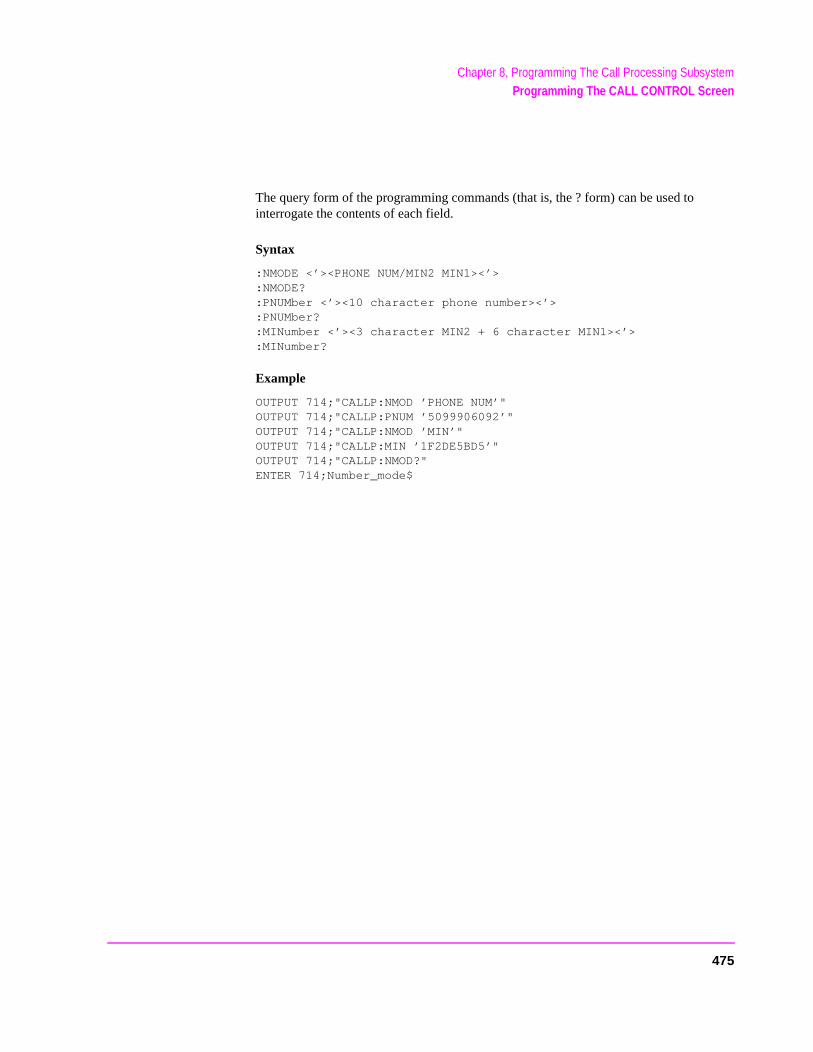
Chapter 8, Programming The Call Processing SubsystemProgramming The CALL CONTROL Screen
The query form of the programming commands (that is, the ? form) can be used to interrogate the contents of each field.
Syntax
:NMODE <’><PHONE NUM/MIN2 MIN1><’>:NMODE?:PNUMber <’><10 character phone number><’>:PNUMber?:MINumber <’><3 character MIN2 + 6 character MIN1><’>:MINumber?
Example
OUTPUT 714;"CALLP:NMOD ’PHONE NUM’"OUTPUT 714;"CALLP:PNUM ’5099906092’"OUTPUT 714;"CALLP:NMOD ’MIN’"OUTPUT 714;"CALLP:MIN ’1F2DE5BD5’"OUTPUT 714;"CALLP:NMOD?"ENTER 714;Number_mode$
475
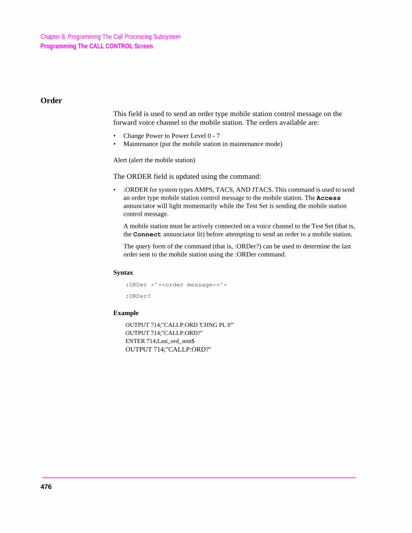
Chapter 8, Programming The Call Processing SubsystemProgramming The CALL CONTROL Screen
end
at is, on.
last
Order
This field is used to send an order type mobile station control message on the forward voice channel to the mobile station. The orders available are:
• Change Power to Power Level 0 - 7• Maintenance (put the mobile station in maintenance mode)
Alert (alert the mobile station)
The ORDER field is updated using the command:
• :ORDER for system types AMPS, TACS, AND JTACS. This command is used to san order type mobile station control message to the mobile station. The Access annunciator will light momentarily while the Test Set is sending the mobile stationcontrol message.
A mobile station must be actively connected on a voice channel to the Test Set (ththe Connect annunciator lit) before attempting to send an order to a mobile stati
The query form of the command (that is, :ORDer?) can be used to determine theorder sent to the mobile station using the :ORDer command.
Syntax
:ORDer <’><order message><’>
:ORDer?
Example
OUTPUT 714;"CALLP:ORD ’CHNG PL 0’"OUTPUT 714;"CALLP:ORD?"ENTER 714;Last_ord_sent$
OUTPUT 714;"CALLP:ORD?"
476
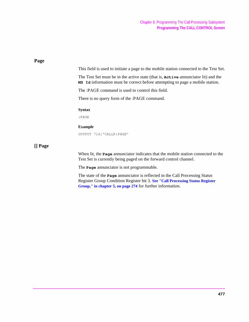
Chapter 8, Programming The Call Processing SubsystemProgramming The CALL CONTROL Screen
Page
This field is used to initiate a page to the mobile station connected to the Test Set.
The Test Set must be in the active state (that is, Active annunciator lit) and the MS Id information must be correct before attempting to page a mobile station.
The :PAGE command is used to control this field.
There is no query form of the :PAGE command.
Syntax
:PAGE
Example
OUTPUT 714;"CALLP:PAGE"
[] Page
When lit, the Page annunciator indicates that the mobile station connected to the Test Set is currently being paged on the forward control channel.
The Page annunciator is not programmable.
The state of the Page annunciator is reflected in the Call Processing Status Register Group Condition Register bit 3. See "Call Processing Status Register Group," in chapter 5, on page 274 for further information.
477

Chapter 8, Programming The Call Processing SubsystemProgramming The CALL CONTROL Screen
Phone Num:
This field displays the phone number decoded from the MIN number received from the mobile station on the reverse control channel in response to a forward control channel message
The Phone Num: field is only displayed when the Display field is set to Data and a reverse control channel message containing this information has been decoded.
Refer to the Display field description, on page 465, for information on how to read data in the upper right hand portion of the CALL CONTROL screen.
CAUTION: Do not confuse the Phone Num: field, which is displayed in the upper right-hand portionof the CALL CONTROL screen, with the Phone Num selection of the MS Id field.
NOTE: An all zero MIN number (000000000), which does not represent a valid phone number, will convert to the following phone number: 111111?111.
478
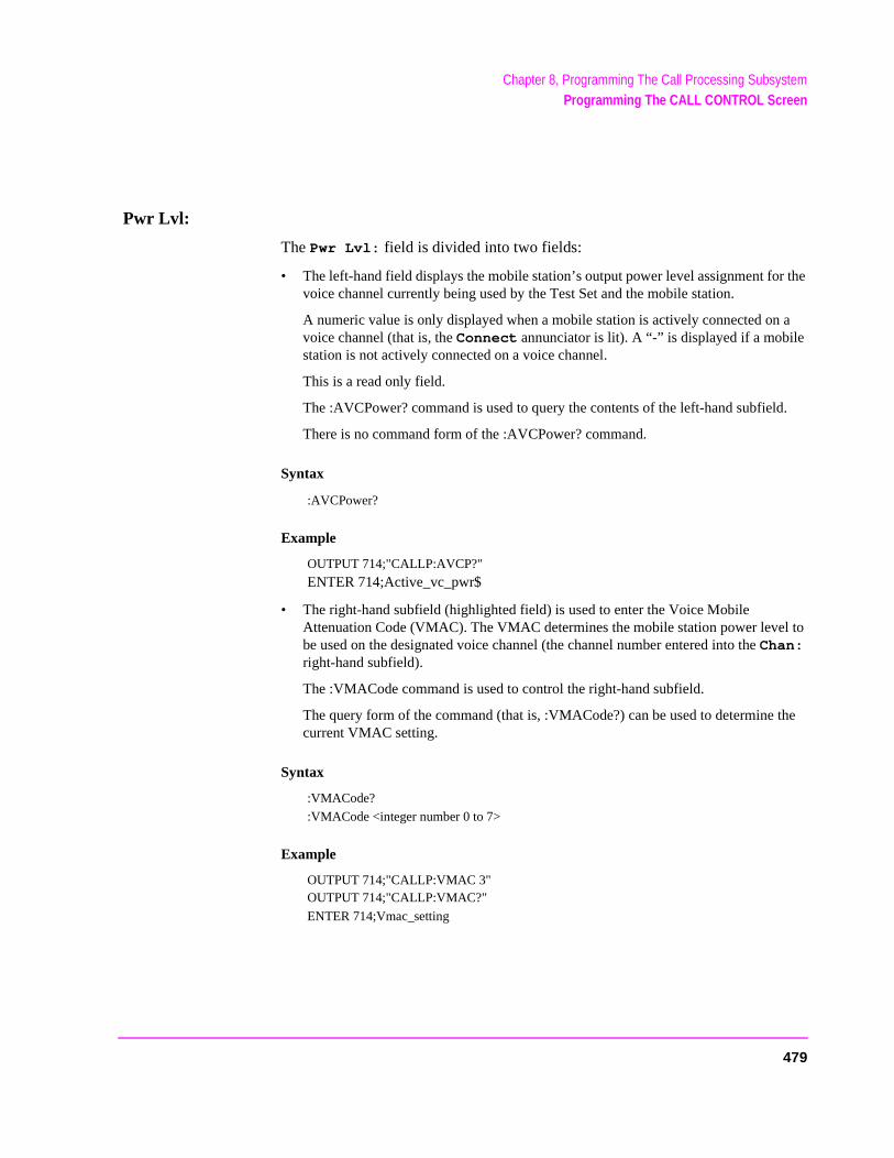
Chapter 8, Programming The Call Processing SubsystemProgramming The CALL CONTROL Screen
r the
a
d.
to
the
Pwr Lvl:
The Pwr Lvl: field is divided into two fields:
• The left-hand field displays the mobile station’s output power level assignment fovoice channel currently being used by the Test Set and the mobile station.
A numeric value is only displayed when a mobile station is actively connected onvoice channel (that is, the Connect annunciator is lit). A “-” is displayed if a mobile station is not actively connected on a voice channel.
This is a read only field.
The :AVCPower? command is used to query the contents of the left-hand subfiel
There is no command form of the :AVCPower? command.
Syntax
:AVCPower?
Example
OUTPUT 714;"CALLP:AVCP?"
ENTER 714;Active_vc_pwr$
• The right-hand subfield (highlighted field) is used to enter the Voice Mobile Attenuation Code (VMAC). The VMAC determines the mobile station power levelbe used on the designated voice channel (the channel number entered into the Chan: right-hand subfield).
The :VMACode command is used to control the right-hand subfield.
The query form of the command (that is, :VMACode?) can be used to determine current VMAC setting.
Syntax
:VMACode?
:VMACode <integer number 0 to 7>
Example
OUTPUT 714;"CALLP:VMAC 3"OUTPUT 714;"CALLP:VMAC?"
ENTER 714;Vmac_setting
479
Chapter 8, Programming The Call Processing SubsystemProgramming The CALL CONTROL Screen
Register
This field is used to initiate a registration of the mobile station connected to the Test Set.
The Test Set must be in the active state (that is, the Active annunciator lit) before attempting to register a mobile station.
The :REGister command is used to control this field.
There is no query form of the :REGister command.
Syntax
:REGister
Example
OUTPUT 714;"CALLP:REG"
[] Register
When lit, the Register annunciator indicates that the mobile station connected to the Test Set is being commanded to register with the Test Set
The Register annunciator is not programmable.
The state of the Register annunciator is reflected in the Call Processing Status Register Group Condition Register bit 1. See “Status Reporting” in the Application Guide for further information.
480
Chapter 8, Programming The Call Processing SubsystemProgramming The CALL CONTROL Screen
Release
This field is used to terminate an active voice channel connection with the mobile station.
When the Release field is selected, a mobile station control message with a Release order is sent to the mobile station on the forward voice channel. A mobile station must be actively connected on a voice channel to the Test Set (that is, the Connect annunciator lit) before attempting to send a release order to the mobile station.
The :RELease command is used to control this field.
There is no query form of the :RELease command.
Syntax
:RELease
Example
OUTPUT 714;"CALLP:REL"
481
Chapter 8, Programming The Call Processing SubsystemProgramming The CALL CONTROL Screen
rrent
a
field.
be
e cur-
SAT:
The SAT: field is divided into two fields:
• The left-hand field displays the current SAT tone frequency assignment for the cuvoice channel being used by the Test Set and the mobile station.
A numeric value is only displayed when a mobile station is actively connected onvoice channel (that is, the Connect annunciator is lit). A “-” is displayed if a mobile station is not actively connected on a voice channel.
This is a read only field.
The :AVCSat? query command is used to query the contents of the left-hand sub
There is no command form of the :AVCSat? command.
Syntax
:AVCSat?
Example
OUTPUT 714;"CALLP:AVCS?"
ENTER 714;Active_vc_sat$
• The right-hand field (highlighted field) is used to set the SAT Color Code (SCC) toused on the designated voice channel (the channel number entered into the Chan: right-hand subfield).
The :SATone command is used to control the right-hand subfield.
The query form of the command (that is, :SATone?) can be used to determine thrent SAT Color Code (SCC) setting.
Syntax
:SATone <’><5970HZ/6000HZ/6030HZ><’>
:SATone?
Example
OUTPUT 714;"CALLP:SAT?"OUTPUT 714;"CALLP:SAT ’5970HZ’"
ENTER 714;Sat_color_code$
482

Chapter 8, Programming The Call Processing SubsystemProgramming The CALL CONTROL Screen
SCM:
This field displays the decoded station class mark information received from the mobile station on the reverse control channel in response to a forward control channel message. The decoded SCM consists of: the mobile station power class (Class I, II, or III), the transmission type (continuous/discontinuous), and the transmission bandwidth (20 MHz or 25 MHz).
The SCM: field is only displayed when the Display field is set to Data and a reverse control channel message has been decoded.
Refer to the Display field description, on page 465, for information on how to read data in the upper right hand portion of the CALL CONTROL screen.
SID
This field is used to set the system identification number (SID) of the Test Set.
The :SIDentify command is used to control this field.
The SID field is an immediate action field. That is, whenever the :SIDentify command is sent, the change is reflected immediately in the appropriate signaling message(s) being sent on the forward control channel. No change occurs to the current state (i.e. Active, Register, Page, Access, Connect) of the Call Processing Subsystem.
The query form of the command (that is, :SIDentify?) can be used to determine the current system identification number (SID) setting.
Syntax
:SIDentify <integer number>:SIDentify?
Example
OUTPUT 714;"CALLP:SID 231"OUTPUT 714;"CALLP:SID?"ENTER 714;Sid_number
483
Chapter 8, Programming The Call Processing SubsystemProgramming The CALL CONTROL Screen
System Type
This field is used to select the type of cellular system (AMPS, TACS, JTACS) which will be simulated.
The :CSYStem command is used to control this field.
The System Type field is an immediate action field. That is, whenever the :CSYStem command is sent, the change is reflected immediately in the physical configuration of the Test Set (the control channel is immediately deactivated, reconfigured, and then reactivated to reflect the change) and causes an immediate change to the current state of the Call Processing Subsystem (the state is set to Active).
NOTE: If the Test Set is in the Connect state and a change is made to the System Type fieldthe Connect state will be lost.
The query form of the command (that is, :CSYStem?) can be used to determine the type of cellular system currently being simulated.
Syntax
:CSYStem <’><AMPS/TACS/JTACS><’>:CSYStem?
Example
OUTPUT 714;"CALLP:CSYS ’AMPS’"OUTPUT 714;"CALLP:CSYS?"
ENTER 714;System_type$
484
Chapter 8, Programming The Call Processing SubsystemProgramming The CALL CONTROL Screen
TX Freq Error
This field displays the frequency error (frequency error = assigned carrier frequency - measured carrier frequency) of the RF carrier being transmitted by the mobile station. Four dashes (----) indicate that no RF carrier is present to measure.
A numeric value would only be displayed in the connected state (that is, the Connect annunciator is lit). The TX Freq Error field is only displayed when the Display field is set to Meas.
Refer to the Display field description, on page 465, for information on how to read data in the upper right hand portion of the CALL CONTROL screen.
TX Power
This field displays the measured RF power of the RF carrier being transmitted by the mobile station.
A nonzero value would only be displayed in the connected state (that is, the Connect annunciator is lit). The TX Power field is only displayed when the Display field is set to Meas.
Refer to the Display field description, on page 465, for information on how to readdata in the upper right hand portion of the CALL CONTROL screen.
485
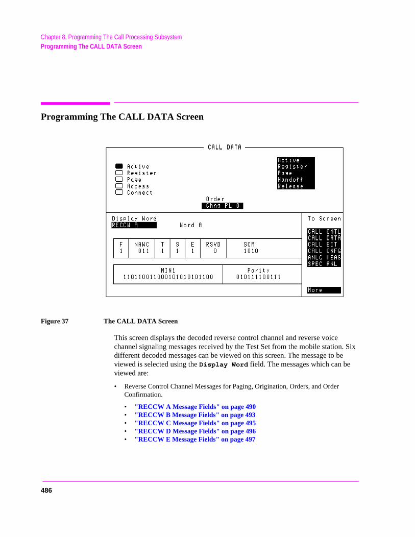
Chapter 8, Programming The Call Processing SubsystemProgramming The CALL DATA Screen
Programming The CALL DATA Screen
Figure 37 The CALL DATA Screen
This screen displays the decoded reverse control channel and reverse voice channel signaling messages received by the Test Set from the mobile station. Six different decoded messages can be viewed on this screen. The message to be viewed is selected using the Display Word field. The messages which can be viewed are:
• Reverse Control Channel Messages for Paging, Origination, Orders, and Order Confirmation.
• "RECCW A Message Fields" on page 490• "RECCW B Message Fields" on page 493• "RECCW C Message Fields" on page 495• "RECCW D Message Fields" on page 496 • "RECCW E Message Fields" on page 497
486
Chapter 8, Programming The Call Processing SubsystemProgramming The CALL DATA Screen
• Reverse Voice Channel Messages for Order Confirmation.
• "RVCOrdCon Message Fields" on page 498
Refer to the User’s Guide for detailed information on the operation and manual use of the CALL DATA screen. .
[] Access
See "[] Access" on page 459 for programming information.
Active
See "Active" on page 459 for programming information.
[] Active
See "[] Active" on page 460 for programming information.
[] Connect
See "[] Connect" on page 464 for programming information.
Display Word
This field is used to select the desired reverse control channel or reverse voice channel message to be displayed.
The :DATA command is used to control this field.
The query form of the command (that is, :DATA?) can be used to determine which reverse control channel or reverse voice channel message is currently being displayed.
487
Chapter 8, Programming The Call Processing SubsystemProgramming The CALL DATA Screen
See "Reading the CALL DATA Screen Message Fields" on page 489 for information on how to read the contents of the individual messages.
Syntax
:DATA <’><RECCW A/RECCW B/RECCW C/RECCW D/RECCW E/RVCOrdCon><’>:DATA?
Example
OUTPUT 714;"CALLP:DATA ’RECCW A’"OUTPUT 714;"CALLP:DATA?"ENTER 714;Message$
Handoff
See "Handoff" on page 473 for programming information.
Order
See "Order" on page 476 for programming information.
Page
See "Page" on page 477 for programming information.
[] Page
See "[] Page" on page 477 for programming information.
See "Register" on page 480 for programming information.
[] Register
See "[] Register" on page 480 for programming information.
Release
See "Release" on page 481 for programming information.
488
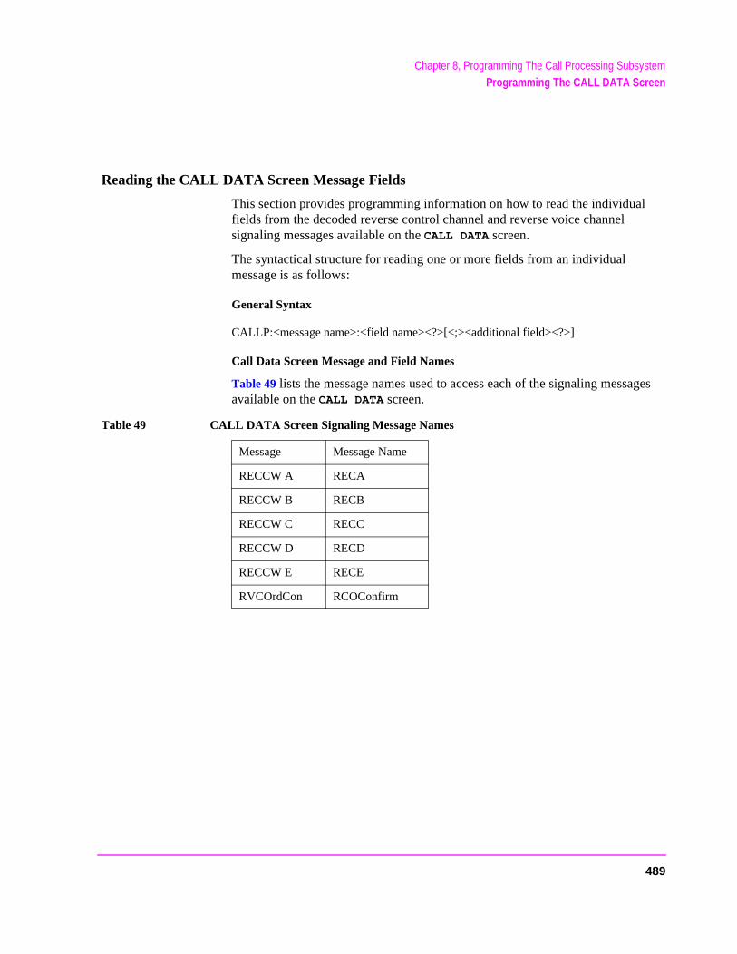
Chapter 8, Programming The Call Processing SubsystemProgramming The CALL DATA Screen
Reading the CALL DATA Screen Message Fields
This section provides programming information on how to read the individual fields from the decoded reverse control channel and reverse voice channel signaling messages available on the CALL DATA screen.
The syntactical structure for reading one or more fields from an individual message is as follows:
General Syntax
CALLP:<message name>:<field name><?>[<;><additional field><?>]
Call Data Screen Message and Field Names
Table 49 lists the message names used to access each of the signaling messages available on the CALL DATA screen.
Table 49 CALL DATA Screen Signaling Message Names
Message Message Name
RECCW A RECA
RECCW B RECB
RECCW C RECC
RECCW D RECD
RECCW E RECE
RVCOrdCon RCOConfirm
489
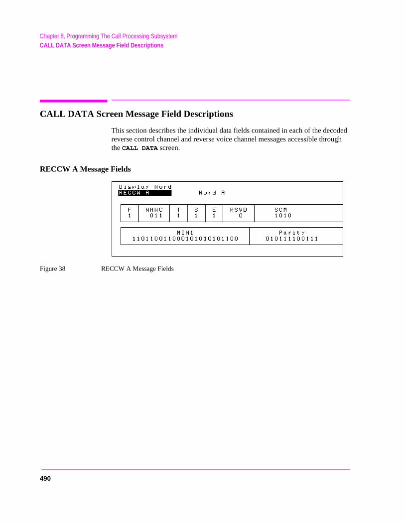
Chapter 8, Programming The Call Processing SubsystemCALL DATA Screen Message Field Descriptions
CALL DATA Screen Message Field Descriptions
This section describes the individual data fields contained in each of the decoded reverse control channel and reverse voice channel messages accessible through the CALL DATA screen.
RECCW A Message Fields
Figure 38 RECCW A Message Fields
490
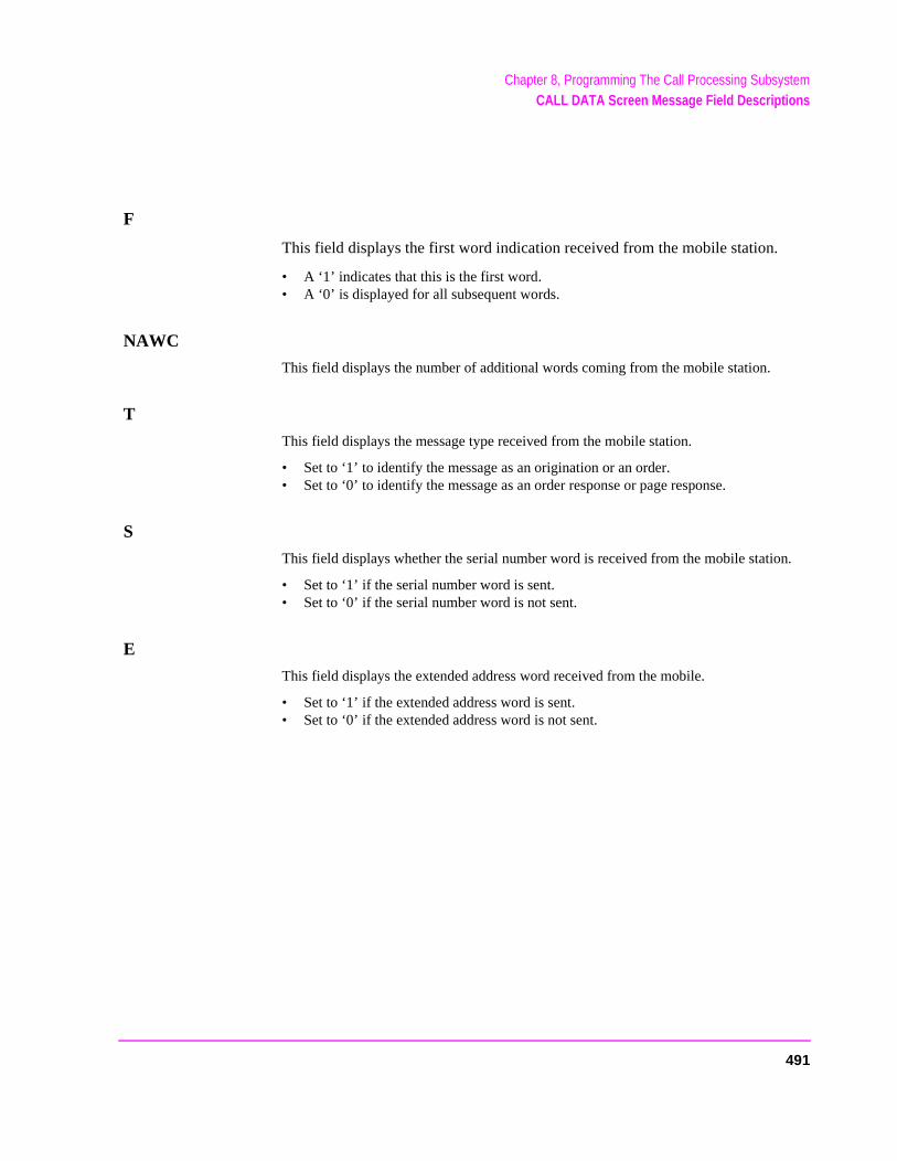
Chapter 8, Programming The Call Processing SubsystemCALL DATA Screen Message Field Descriptions
n.
F
This field displays the first word indication received from the mobile station.
• A ‘1’ indicates that this is the first word. • A ‘0’ is displayed for all subsequent words.
NAWC
This field displays the number of additional words coming from the mobile station.
T
This field displays the message type received from the mobile station.
• Set to ‘1’ to identify the message as an origination or an order. • Set to ‘0’ to identify the message as an order response or page response.
S
This field displays whether the serial number word is received from the mobile statio
• Set to ‘1’ if the serial number word is sent. • Set to ‘0’ if the serial number word is not sent.
E
This field displays the extended address word received from the mobile.
• Set to ‘1’ if the extended address word is sent. • Set to ‘0’ if the extended address word is not sent.
491

Chapter 8, Programming The Call Processing SubsystemCALL DATA Screen Message Field Descriptions
RSVD
This field is reserved for future use.
SCM
This field displays the mobile station’s received station class mark.
MIN1
This field displays the first part of the mobile identification number received from themobile station.
Parity
This field displays the parity of the transmitted data.
492
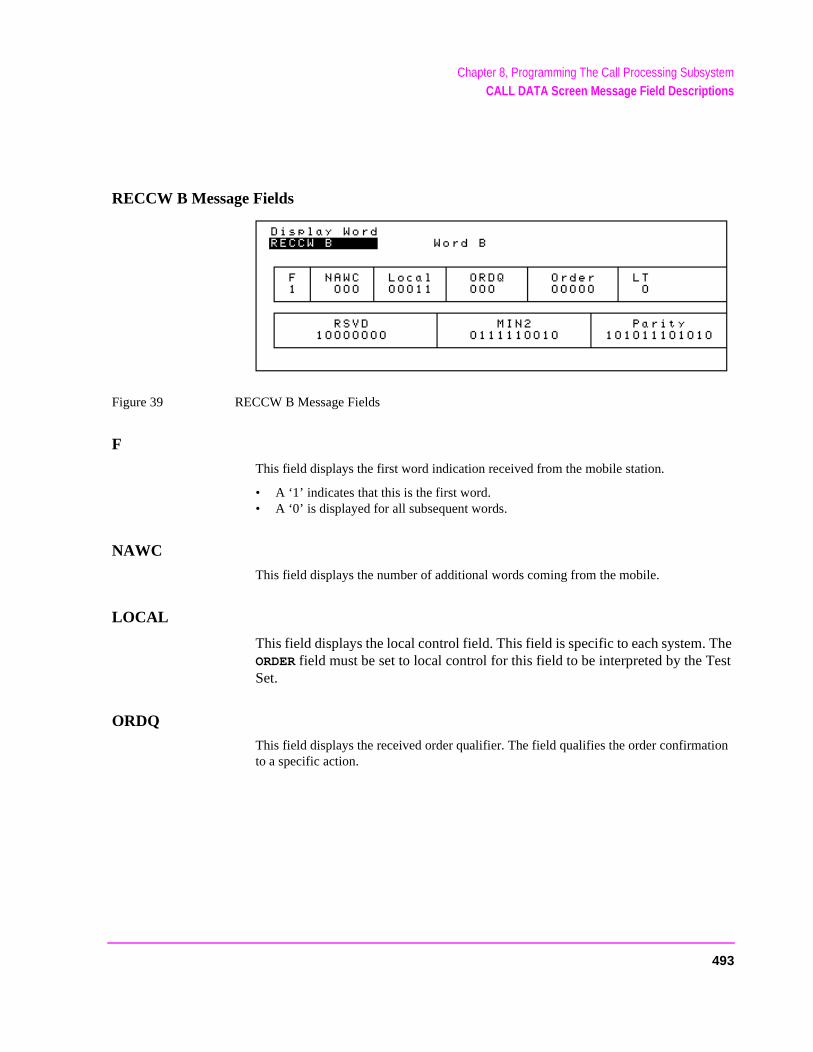
Chapter 8, Programming The Call Processing SubsystemCALL DATA Screen Message Field Descriptions
ion
RECCW B Message Fields
Figure 39 RECCW B Message Fields
F
This field displays the first word indication received from the mobile station.
• A ‘1’ indicates that this is the first word. • A ‘0’ is displayed for all subsequent words.
NAWC
This field displays the number of additional words coming from the mobile.
LOCAL
This field displays the local control field. This field is specific to each system. The ORDER field must be set to local control for this field to be interpreted by the Test Set.
ORDQ
This field displays the received order qualifier. The field qualifies the order confirmatto a specific action.
493
Chapter 8, Programming The Call Processing SubsystemCALL DATA Screen Message Field Descriptions
ORDER
This field displays the Order field and identifies the order type received by the Test Set.
LT
This field displays the last-try code field.
RSVD
Reserved for future use.
MIN2
This field displays the second part of the mobile identification number received by the Test Set.
Parity
This field displays the parity of the received data.
494
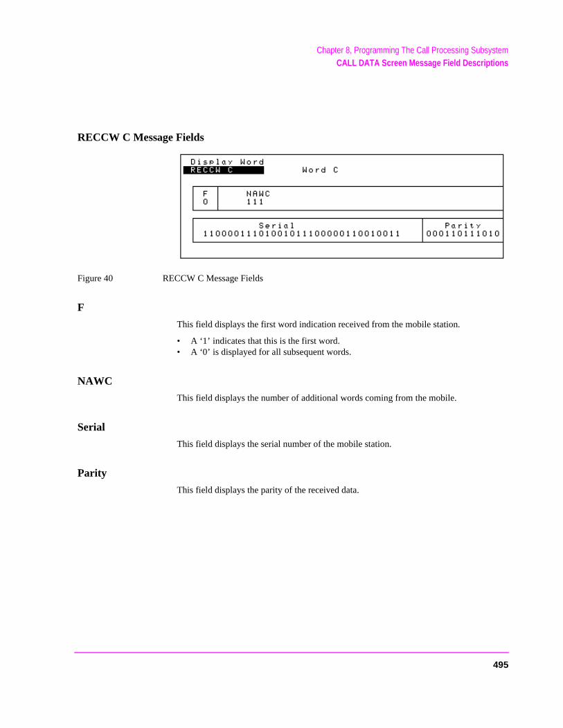
Chapter 8, Programming The Call Processing SubsystemCALL DATA Screen Message Field Descriptions
RECCW C Message Fields
Figure 40 RECCW C Message Fields
F
This field displays the first word indication received from the mobile station.
• A ‘1’ indicates that this is the first word. • A ‘0’ is displayed for all subsequent words.
NAWC
This field displays the number of additional words coming from the mobile.
Serial
This field displays the serial number of the mobile station.
Parity
This field displays the parity of the received data.
495
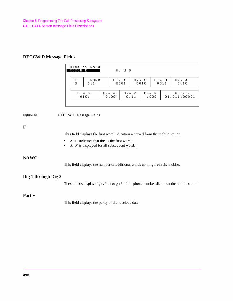
Chapter 8, Programming The Call Processing SubsystemCALL DATA Screen Message Field Descriptions
tion.
RECCW D Message Fields
Figure 41 RECCW D Message Fields
F
This field displays the first word indication received from the mobile station.
• A ‘1’ indicates that this is the first word. • A ‘0’ is displayed for all subsequent words.
NAWC
This field displays the number of additional words coming from the mobile.
Dig 1 through Dig 8
These fields display digits 1 through 8 of the phone number dialed on the mobile sta
Parity
This field displays the parity of the received data.
496
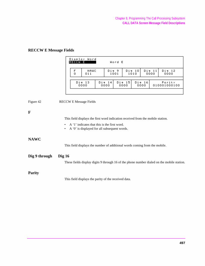
Chapter 8, Programming The Call Processing SubsystemCALL DATA Screen Message Field Descriptions
ation.
RECCW E Message Fields
Figure 42 RECCW E Message Fields
F
This field displays the first word indication received from the mobile station.
• A ‘1’ indicates that this is the first word. • A ‘0’ is displayed for all subsequent words.
NAWC
This field displays the number of additional words coming from the mobile.
Dig 9 through Dig 16
These fields display digits 9 through 16 of the phone number dialed on the mobile st
Parity
This field displays the parity of the received data.
497
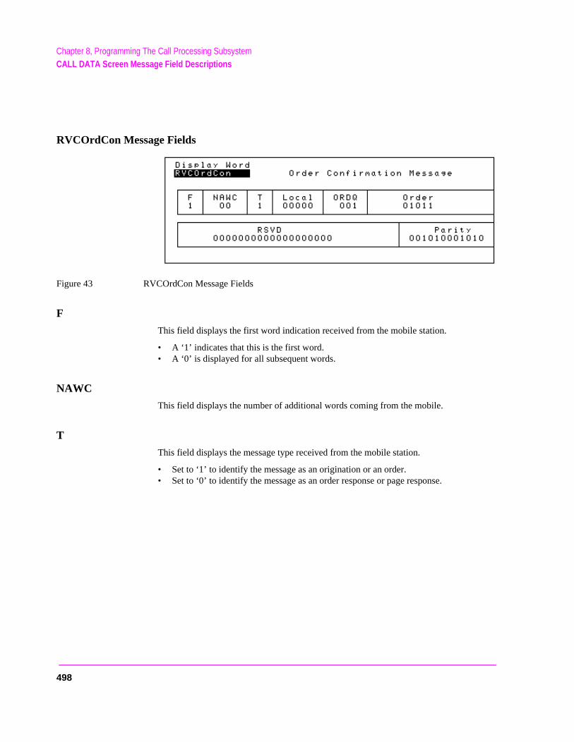
Chapter 8, Programming The Call Processing SubsystemCALL DATA Screen Message Field Descriptions
RVCOrdCon Message Fields
Figure 43 RVCOrdCon Message Fields
F
This field displays the first word indication received from the mobile station.
• A ‘1’ indicates that this is the first word. • A ‘0’ is displayed for all subsequent words.
NAWC
This field displays the number of additional words coming from the mobile.
T
This field displays the message type received from the mobile station.
• Set to ‘1’ to identify the message as an origination or an order. • Set to ‘0’ to identify the message as an order response or page response.
498
Chapter 8, Programming The Call Processing SubsystemCALL DATA Screen Message Field Descriptions
Local
This field displays the local control field. This field is specific to each system. The ORDER field must be set to local control for this field to be interpreted by the Test Set.
ORDQ
This field displays the received order qualifier. The field qualifies the order confirmation to a specific action.
Order
This field displays the Order field and identifies the order type received by the Test Set.
RSVD
Reserved for future use.
Parity
This field displays the parity of the received data.
499
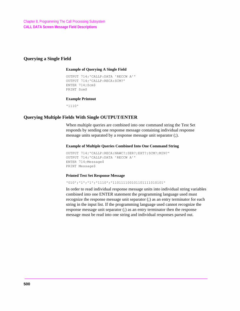
Chapter 8, Programming The Call Processing SubsystemCALL DATA Screen Message Field Descriptions
Querying a Single Field
Example of Querying A Single Field
OUTPUT 714;"CALLP:DATA ’RECCW A’"OUTPUT 714;"CALLP:RECA:SCM?"ENTER 714;Scm$PRINT Scm$
Example Printout
"1110"
Querying Multiple Fields With Single OUTPUT/ENTER
When multiple queries are combined into one command string the Test Set responds by sending one response message containing individual response message units separated by a response message unit separator (;).
Example of Multiple Queries Combined Into One Command String
OUTPUT 714;"CALLP:RECA:NAWC?;SER?;EXT?;SCM?;MIN?"OUTPUT 714;"CALLP:DATA ’RECCW A’"ENTER 714;Message$ PRINT Message$
Printed Test Set Response Message
"010";"1";"1";"1110";"110111100101101111010101"
In order to read individual response message units into individual string variables combined into one ENTER statement the programming language used must recognize the response message unit separator (;) as an entry terminator for each string in the input list. If the programming language used cannot recognize the response message unit separator (;) as an entry terminator then the response message must be read into one string and individual responses parsed out.
500
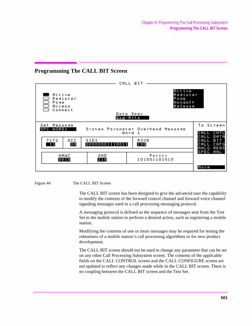
Chapter 8, Programming The Call Processing SubsystemProgramming The CALL BIT Screen
t
be set ble e re is
Programming The CALL BIT Screen
Figure 44 The CALL BIT Screen
The CALL BIT screen has been designed to give the advanced user the capability to modify the contents of the forward control channel and forward voice channel signaling messages used in a call processing messaging protocol.
A messaging protocol is defined as the sequence of messages sent from the Test Set to the mobile station to perform a desired action, such as registering a mobile station.
Modifying the contents of one or more messages may be required for testing the robustness of a mobile station’s call processing algorithms or for new producdevelopment.
The CALL BIT screen should not be used to change any parameter that can on any other Call Processing Subsystem screen. The contents of the applicafields on the CALL CONTROL screen and the CALL CONFIGURE screen arnot updated to reflect any changes made while in the CALL BIT screen. Theno coupling between the CALL BIT screen and the Test Set.
501
Chapter 8, Programming The Call Processing SubsystemProgramming The CALL BIT Screen
and
For example: changing the value of the SAT color code field (SCC) in the forward control channel mobile station control message (MS IntVCh) does not change the setting of the SAT: field on the CALL CONTROL screen.
When using the CALL BIT screen the user is responsible for setting the contents of all messages used in a messaging protocol. When using the CALL BIT screen the Call Processing Subsystem host firmware sends the correct message(s) at the correct time(s) as defined in the applicable industry standard. Message content is the responsibility of the user.
Using the CALL BIT screen requires expert knowledge of the call processing messaging protocols used in the selected system (that is, the system selected in the System Type field on the CALL CONTROL screen).
The contents of eleven different messages can be modified from this screen. The message to be modified is selected using the Set Message field. The eleven messages whose contents can be modified are:
• Forward Control Channel Messages for Paging, Origination, Order Confirmation,orders.
• "SPC WORD1 Message Fields" on page 512 • "SPC WORD2 Message Fields" on page 514 • "ACCESS Message Fields" on page 517• "REG INC Message Fields" on page 519• "REG ID Message Fields" on page 521• "C-FILMESS Message Fields" on page 522• "MS WORD1 Message Fields" on page 524• "MSMessOrd Message Fields" on page 525• "MS IntVCh Message Fields" on page 527• "FVC O Mes Message Fields" on page 528
• "FVC V Mes Message Fields" on page 530
502

Chapter 8, Programming The Call Processing SubsystemProgramming The CALL BIT Screen
sage
roed sult in
When the CALL BIT screen is displayed and the Call Processing Subsystem is in the Connect state, the host firmware constantly monitors the mobile station’stransmitted carrier power. If the power falls below 0.0005 Watts the error mesRF Power Loss indicates loss of Voice Channel will be displayed and the Test Set will terminate the call and return to the Active state.
In order to ensure that the host firmware makes the correct decisions regarding the pres-ence of the mobile stations’s RF carrier, the Test Set’s RF power meter should be zebefore using the Call Processing Subsystem. Failure to zero the power meter can reerroneous RF power measurements. See"Conditioning the Test Set for Call Process-ing" on page 452 for information on zeroing the RF Power meter manually.
Refer to the User’s Guide for detailed information on the operation and manual use of the CALL BIT screen. The field descriptions for each of the decoded messages are given in the “CALL BIT Screen Message Field Descriptions” section of “Call Processing Subsystem” chapter, in the User’s Guide.
The information presented in this section covers the CALL BIT screen programming commands and how to use them.
503
Chapter 8, Programming The Call Processing SubsystemProgramming The CALL BIT Screen
[] Access
See "[] Access" on page 459 for programming information.
Active
See "Active" on page 459 for programming information.
[] Active
See "[] Active" on page 460 for programming information.
[] Connect
See "[] Connect" on page 464 for programming information.
504
Chapter 8, Programming The Call Processing SubsystemProgramming The CALL BIT Screen
the
never the
trol
ering sing
es the
ode. ile sta-d the )
ce nt be set
Data Spec
This field is used to determine how the contents of the signaling messages are built.
• Std = Use the signaling formats defined in the applicable industry standard to buildforward control channel and forward voice channel signaling messages. Use the contents of the applicable fields on the CALL CONTROL screen and the CALL CONFIGURE screen to obtain information necessary to build the messages. Whea signaling message is used, update the contents of all fields in that message onCALL BIT screen.
• Bits = Use the bit patterns as set on the CALL BIT screen to build all forward conchannel and forward voice channel signaling messages. For any call processing function (that is, setting the message stream on the active control channel, registthe mobile station, paging the mobile station, handing off the mobile station or releathe mobile station) the user is responsible for setting the contents of all signalingmessages used in that function. The Call Processing Subsystem host firmware usmessaging protocol as defined in the applicable industry standard.
The contents of the applicable fields on the CALL CONTROL screen and the CALL CONFIGURE screen are not updated to reflect any changes made while in the Bits mThere is no coupling between the Bits mode and the Test Set. For example: if a mobtion was actively connected to the Test Set on a voice channel and the user changeCHAN field on the forward voice channel mobile station control message (FVC V Mesand sent that message to the mobile station, the mobile station would change its voichannel assignment. However, the Test Set will stay on the voice channel assignmespecified in the Chan:field on the CALL CONTROL screen. This situation will result ina dropped call. The Bits mode should not be used to change any parameter that canon any other Call Processing Subsystem screen.
The :DSPecifier command is used to control this field.
The query form of the command (that is, :DSPecifier?) can be used to determine which method is currently being used to build the contents of the signaling messages.
505
Chapter 8, Programming The Call Processing SubsystemProgramming The CALL BIT Screen
See "Reading the CALL BIT Screen Message Fields" on page 509 for information on how to read the contents of the individual messages.
Syntax
:DSPecifier <’><STD/BITS><’>:DSPecifier?
Example
OUTPUT 714;"CALLP:DSP?"OUTPUT 714;"CALLP:DSP ’STD’"ENTER 714;Build_method$
Handoff
See "Handoff" on page 473 for programming information.
Order
This field is used to send an order type mobile station control message on the forward voice channel to the Mobile Station. The orders available are:
• Change Power to Power Level 0 - 7• Maintenance (put the mobile station in maintenance mode) • Alert (alert the mobile station)
The Order field is a one-of-many selection field. To send an order to the mobile station position the cursor on the Order field and select it. A list of choices is displayed. Position the cursor on the desired order and select it. Once the selection is made a mobile station control message is sent to the Mobile Station. The Access annunciator will light momentarily while the Test Set is sending the mobile station control message.
A mobile station must be actively connected on a voice channel to the Test Set (that is, the Connect annunciator lit) before attempting to send an order to a mobile station.
506
Chapter 8, Programming The Call Processing SubsystemProgramming The CALL BIT Screen
Page
See "Page" on page 477 for programming information.
[] Page
See "[] Page" on page 477 for programming information.
Register
See "Register" on page 480 for programming information.
[] Register
See "[] Register" on page 480 for programming information.
Release
See "Release" on page 481 for programming information.
507
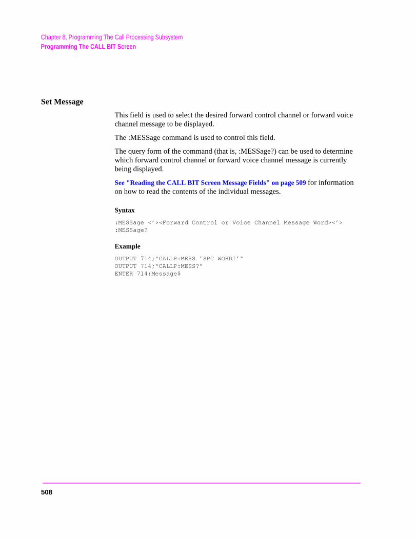
Chapter 8, Programming The Call Processing SubsystemProgramming The CALL BIT Screen
Set Message
This field is used to select the desired forward control channel or forward voice channel message to be displayed.
The :MESSage command is used to control this field.
The query form of the command (that is, :MESSage?) can be used to determine which forward control channel or forward voice channel message is currently being displayed.
See "Reading the CALL BIT Screen Message Fields" on page 509 for information on how to read the contents of the individual messages.
Syntax
:MESSage <’><Forward Control or Voice Channel Message Word><’>:MESSage?
Example
OUTPUT 714;"CALLP:MESS ’SPC WORD1’"OUTPUT 714;"CALLP:MESS?"ENTER 714;Message$
508
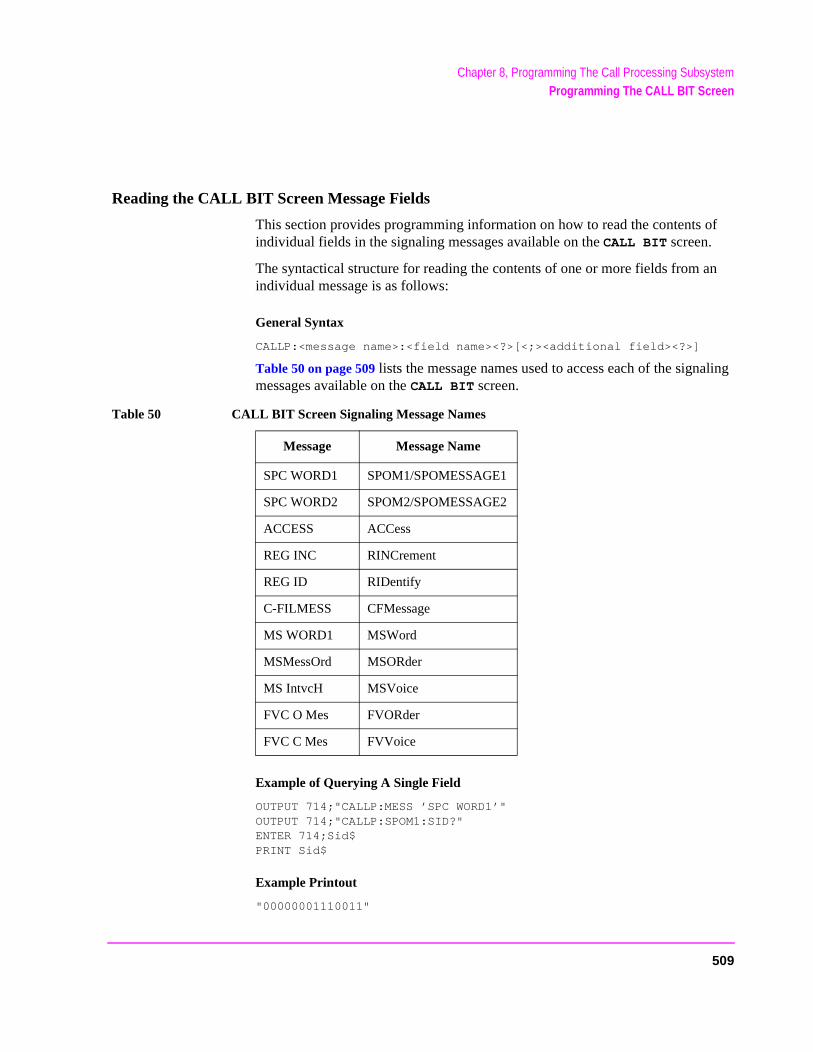
Chapter 8, Programming The Call Processing SubsystemProgramming The CALL BIT Screen
Reading the CALL BIT Screen Message Fields
This section provides programming information on how to read the contents of individual fields in the signaling messages available on the CALL BIT screen.
The syntactical structure for reading the contents of one or more fields from an individual message is as follows:
General Syntax
CALLP:<message name>:<field name><?>[<;><additional field><?>]
Table 50 on page 509 lists the message names used to access each of the signaling messages available on the CALL BIT screen.
Example of Querying A Single Field
OUTPUT 714;"CALLP:MESS ’SPC WORD1’"OUTPUT 714;"CALLP:SPOM1:SID?"ENTER 714;Sid$ PRINT Sid$
Example Printout
"00000001110011"
Table 50 CALL BIT Screen Signaling Message Names
Message Message Name
SPC WORD1 SPOM1/SPOMESSAGE1
SPC WORD2 SPOM2/SPOMESSAGE2
ACCESS ACCess
REG INC RINCrement
REG ID RIDentify
C-FILMESS CFMessage
MS WORD1 MSWord
MSMessOrd MSORder
MS IntvcH MSVoice
FVC O Mes FVORder
FVC C Mes FVVoice
509

Chapter 8, Programming The Call Processing SubsystemProgramming The CALL BIT Screen
Querying Multiple Fields With Single OUTPUT/ENTER
When multiple querries are combined into one command string the Test Set responds by sending one response message containing individual response message units separated by a response message unit separator (;).
Example of Multiple Querries Combined Into One Command String
OUTPUT 714;"CALLP:MESS ’SPC WORD1’"OUTPUT 714;"CALLP:SPOM1:DCC?;SID?;OHD?"ENTER 714;Message$ PRINT Message$
Printed Test Set Response Message
"01";"00000001110011";"110"
In order to read individual response message units into individual string variables combined into one ENTER statement the programming language used must recognize the response message unit separator (;) as an entry terminator for each string in the input list. If the programming language used cannot recognize the response message unit separator (;) as an entry terminator then the response message must be read into one string and individual responses parsed out.
510
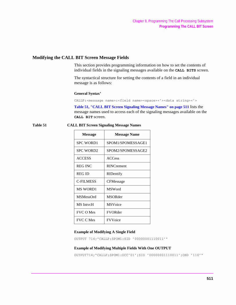
Chapter 8, Programming The Call Processing SubsystemProgramming The CALL BIT Screen
Modifying the CALL BIT Screen Message Fields
This section provides programming information on how to set the contents of individual fields in the signaling messages available on the CALL BITS screen.
The syntactical structure for setting the contents of a field in an individual message is as follows:
General Syntax’
CALLP:<message name>:<field name><space><’><data string><’>
Table 51, "CALL BIT Screen Signaling Message Names" on page 511 lists the message names used to access each of the signaling messages available on the CALL BIT screen.
Example of Modifying A Single Field
OUTPUT 714;"CALLP:SPOM1:SID ’00000001110011’"
Example of Modifying Multiple Fields With One OUTPUT
OUTPUT714;"CALLP:SPOM1:DCC’01’;SID ’00000001110011’;OHD ’110’"
Table 51 CALL BIT Screen Signaling Message Names
Message Message Name
SPC WORD1 SPOM1/SPOMESSAGE1
SPC WORD2 SPOM2/SPOMESSAGE2
ACCESS ACCess
REG INC RINCrement
REG ID RIDentify
C-FILMESS CFMessage
MS WORD1 MSWord
MSMessOrd MSORder
MS IntvcH MSVoice
FVC O Mes FVORder
FVC C Mes FVVoice
511
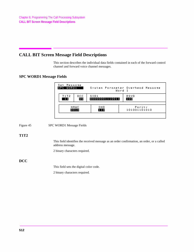
Chapter 8, Programming The Call Processing SubsystemCALL BIT Screen Message Field Descriptions
CALL BIT Screen Message Field Descriptions
This section describes the individual data fields contained in each of the forward control channel and forward voice channel messages.
SPC WORD1 Message Fields
Figure 45 SPC WORD1 Message Fields
T1T2
This field identifies the received message as an order confirmation, an order, or a called address message.
2 binary characters required.
DCC
This field sets the digital color code.
2 binary characters required.
512
Chapter 8, Programming The Call Processing SubsystemCALL BIT Screen Message Field Descriptions
sage.age.
SID1
First part of the system identification field. The field contains the decimal equivalent of the 14 most significant bits of the system identification number.
14 binary characters required.
RSVD
Reserved for future use.
3 binary characters required.
NAWC
This field displays the number of additional words coming.
4 binary characters required.
OHD
This field displays the overhead message type.
• A ‘100’ indicates a global action message.• A ‘110’ indicates that this is the first word of the system overhead parameter mes• A ‘111’ indicates this is the second word of the system parameter overhead mess
3 binary characters required.
Parity
Parity field. The contents of the Parity field cannot be set by the user. The Test Set calculates the parity bits.
513
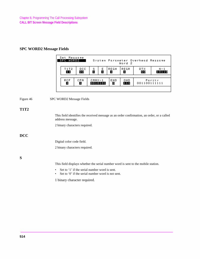
Chapter 8, Programming The Call Processing SubsystemCALL BIT Screen Message Field Descriptions
SPC WORD2 Message Fields
Figure 46 SPC WORD2 Message Fields
T1T2
This field identifies the received message as an order confirmation, an order, or a called address message.
2 binary characters required.
DCC
Digital color code field.
2 binary characters required.
S
This field displays whether the serial number word is sent to the mobile station.
• Set to ‘1’ if the serial number word is sent. • Set to ‘0’ if the serial number word is not sent.
1 binary character required.
514
Chapter 8, Programming The Call Processing SubsystemCALL BIT Screen Message Field Descriptions
E
This field displays the extended address word sent to the mobile.
• Set to ‘1’ if the extended address word is sent. • Set to ‘0’ if the extended address word is not sent.
1 binary character required.
REGH
Registration field for home stations.
1 binary character required.
REGR
Registration field for roaming stations.
1 binary character required.
DTX
Discontinuous transmission field.
2 binary characters required.
N-1
N is the number of paging channels in the system.
5 binary characters required.
RCF
Read-control-filler field.
1 binary character required.
515
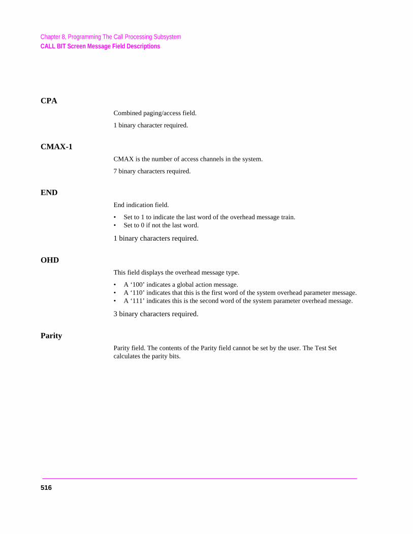
Chapter 8, Programming The Call Processing SubsystemCALL BIT Screen Message Field Descriptions
sage.age.
CPA
Combined paging/access field.
1 binary character required.
CMAX-1
CMAX is the number of access channels in the system.
7 binary characters required.
END
End indication field.
• Set to 1 to indicate the last word of the overhead message train.• Set to 0 if not the last word.
1 binary characters required.
OHD
This field displays the overhead message type.
• A ‘100’ indicates a global action message.• A ‘110’ indicates that this is the first word of the system overhead parameter mes• A ‘111’ indicates this is the second word of the system parameter overhead mess
3 binary characters required.
Parity
Parity field. The contents of the Parity field cannot be set by the user. The Test Set calculates the parity bits.
516
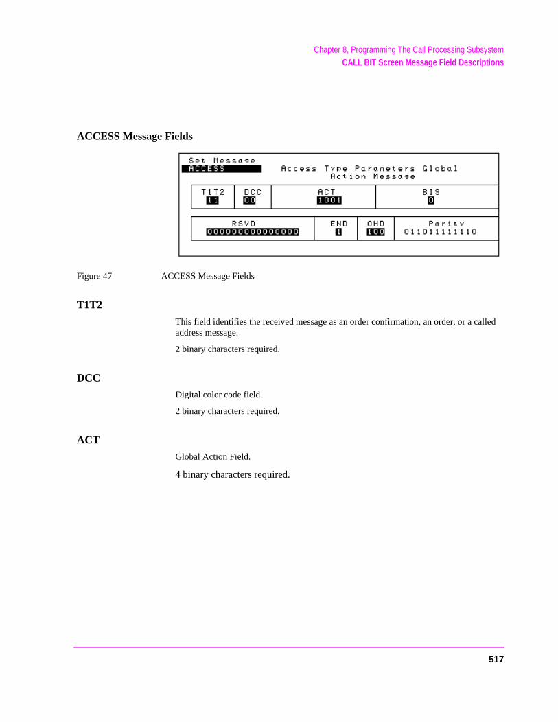
Chapter 8, Programming The Call Processing SubsystemCALL BIT Screen Message Field Descriptions
ACCESS Message Fields
Figure 47 ACCESS Message Fields
T1T2
This field identifies the received message as an order confirmation, an order, or a called address message.
2 binary characters required.
DCC
Digital color code field.
2 binary characters required.
ACT
Global Action Field.
4 binary characters required.
517
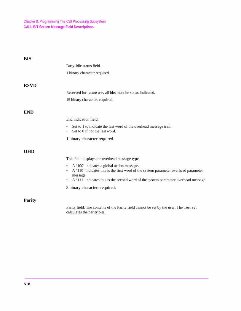
Chapter 8, Programming The Call Processing SubsystemCALL BIT Screen Message Field Descriptions
er
sage.
BIS
Busy-Idle status field.
1 binary character required.
RSVD
Reserved for future use, all bits must be set as indicated.
15 binary characters required.
END
End indication field.
• Set to 1 to indicate the last word of the overhead message train.• Set to 0 if not the last word.
1 binary character required.
OHD
This field displays the overhead message type.
• A ‘100’ indicates a global action message.• A ‘110’ indicates this is the first word of the system parameter overhead paramet
message.• A ‘111’ indicates this is the second word of the system parameter overhead mes
3 binary characters required.
Parity
Parity field. The contents of the Parity field cannot be set by the user. The Test Set calculates the parity bits.
518
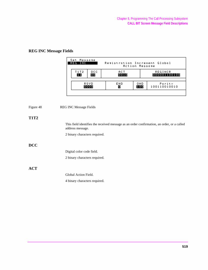
Chapter 8, Programming The Call Processing SubsystemCALL BIT Screen Message Field Descriptions
REG INC Message Fields
Figure 48 REG INC Message Fields
T1T2
This field identifies the received message as an order confirmation, an order, or a called address message.
2 binary characters required.
DCC
Digital color code field.
2 binary characters required.
ACT
Global Action Field.
4 binary characters required.
519
Chapter 8, Programming The Call Processing SubsystemCALL BIT Screen Message Field Descriptions
er
sage.
REGINCR
Registration increment field.
12 binary characters required.
RSVD
Reserved for future use, all bits must be set as indicated.
4 binary characters required.
END
End indication field.
• Set to 1 to indicate the last word of the overhead message train.• Set to 0 if not the last word.
1 binary character required.
OHD
This field displays the overhead message type.
• A ‘100’ indicates a global action message.• A ‘110’ indicates this is the first word of the system parameter overhead paramet
message.• A ‘111’ indicates this is the second word of the system parameter overhead mes
3 binary character required.
Parity
Parity field. The contents of the Parity field cannot be set by the user. The Test Set calculates the parity bits.
520
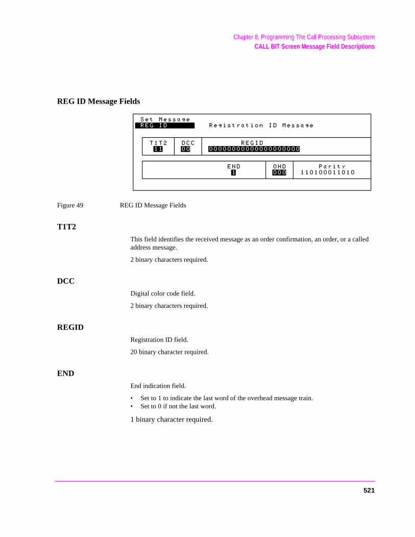
Chapter 8, Programming The Call Processing SubsystemCALL BIT Screen Message Field Descriptions
REG ID Message Fields
Figure 49 REG ID Message Fields
T1T2
This field identifies the received message as an order confirmation, an order, or a called address message.
2 binary characters required.
DCC
Digital color code field.
2 binary characters required.
REGID
Registration ID field.
20 binary character required.
END
End indication field.
• Set to 1 to indicate the last word of the overhead message train.• Set to 0 if not the last word.
1 binary character required.
521
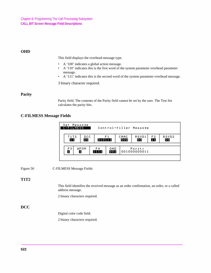
Chapter 8, Programming The Call Processing SubsystemCALL BIT Screen Message Field Descriptions
er
sage.
lled
OHD
This field displays the overhead message type.
• A ‘100’ indicates a global action message.• A ‘110’ indicates this is the first word of the system parameter overhead paramet
message.• A ‘111’ indicates this is the second word of the system parameter overhead mes
3 binary character required.
Parity
Parity field. The contents of the Parity field cannot be set by the user. The Test Set calculates the parity bits.
C-FILMESS Message Fields
Figure 50 C-FILMESS Message Fields
T1T2
This field identifies the received message as an order confirmation, an order, or a caaddress message.
2 binary characters required.
DCC
Digital color code field.
2 binary characters required.
522
Chapter 8, Programming The Call Processing SubsystemCALL BIT Screen Message Field Descriptions
CMAC
Control mobile attenuation field. Indicates the mobile station power level associated with reverse control channel.
3 binary character required.
RSVD1
Reserved for future use, all bits must be set as indicated.
2 binary characters required.
F2
Control filler message field 2. All bits must be set as indicated.
2 binary characters required
RSVD2
Reserved for future use, all bits must be set as indicated.
2 binary characters required.
F3
Control filler message field 3. All bits must be set as indicated.
1 binary character required.
WFOM
Wait-for-overhead-message field.
1 binary character required.
523
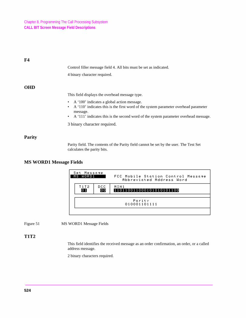
Chapter 8, Programming The Call Processing SubsystemCALL BIT Screen Message Field Descriptions
er
sage.
lled
F4
Control filler message field 4. All bits must be set as indicated.
4 binary character required.
OHD
This field displays the overhead message type.
• A ‘100’ indicates a global action message.• A ‘110’ indicates this is the first word of the system parameter overhead paramet
message.• A ‘111’ indicates this is the second word of the system parameter overhead mes
3 binary character required.
Parity
Parity field. The contents of the Parity field cannot be set by the user. The Test Set calculates the parity bits.
MS WORD1 Message Fields
Figure 51 MS WORD1 Message Fields
T1T2
This field identifies the received message as an order confirmation, an order, or a caaddress message.
2 binary characters required.
524
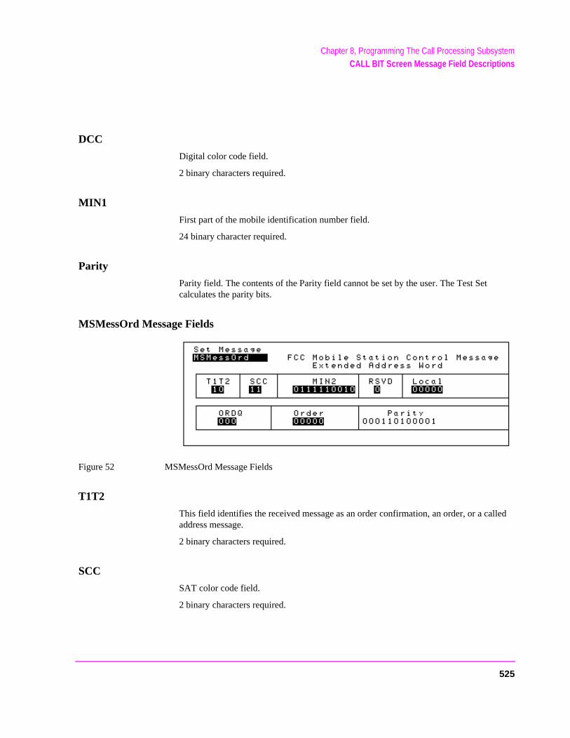
Chapter 8, Programming The Call Processing SubsystemCALL BIT Screen Message Field Descriptions
DCC
Digital color code field.
2 binary characters required.
MIN1
First part of the mobile identification number field.
24 binary character required.
Parity
Parity field. The contents of the Parity field cannot be set by the user. The Test Set calculates the parity bits.
MSMessOrd Message Fields
Figure 52 MSMessOrd Message Fields
T1T2
This field identifies the received message as an order confirmation, an order, or a called address message.
2 binary characters required.
SCC
SAT color code field.
2 binary characters required.
525
Chapter 8, Programming The Call Processing SubsystemCALL BIT Screen Message Field Descriptions
MIN2
Second part of the mobile identification number field.
10 binary character required.
RSVD
Reserved for future use, all bits must be set as indicated.
1 binary character required.
LOCAL
This field is specific to each system. The ORDER field must be set to local control for this field to be interpreted.
5 binary character required.
ORDQ
The order qualifier field qualifies the order confirmation to a specific action.
3 binary character required.
ORDER
This field identifies the order type.
5 binary character required.
Parity
Parity field. The contents of the Parity field cannot be set by the user. The Test Set calculates the parity bits.
526
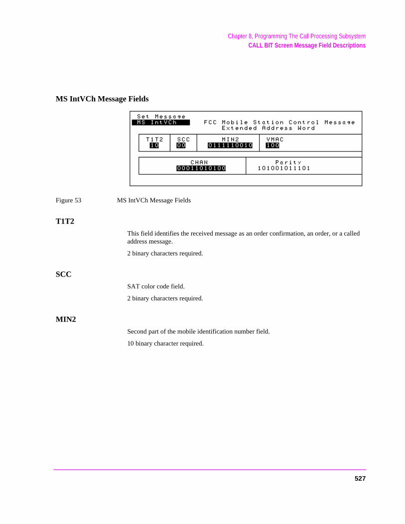
Chapter 8, Programming The Call Processing SubsystemCALL BIT Screen Message Field Descriptions
MS IntVCh Message Fields
Figure 53 MS IntVCh Message Fields
T1T2
This field identifies the received message as an order confirmation, an order, or a called address message.
2 binary characters required.
SCC
SAT color code field.
2 binary characters required.
MIN2
Second part of the mobile identification number field.
10 binary character required.
527
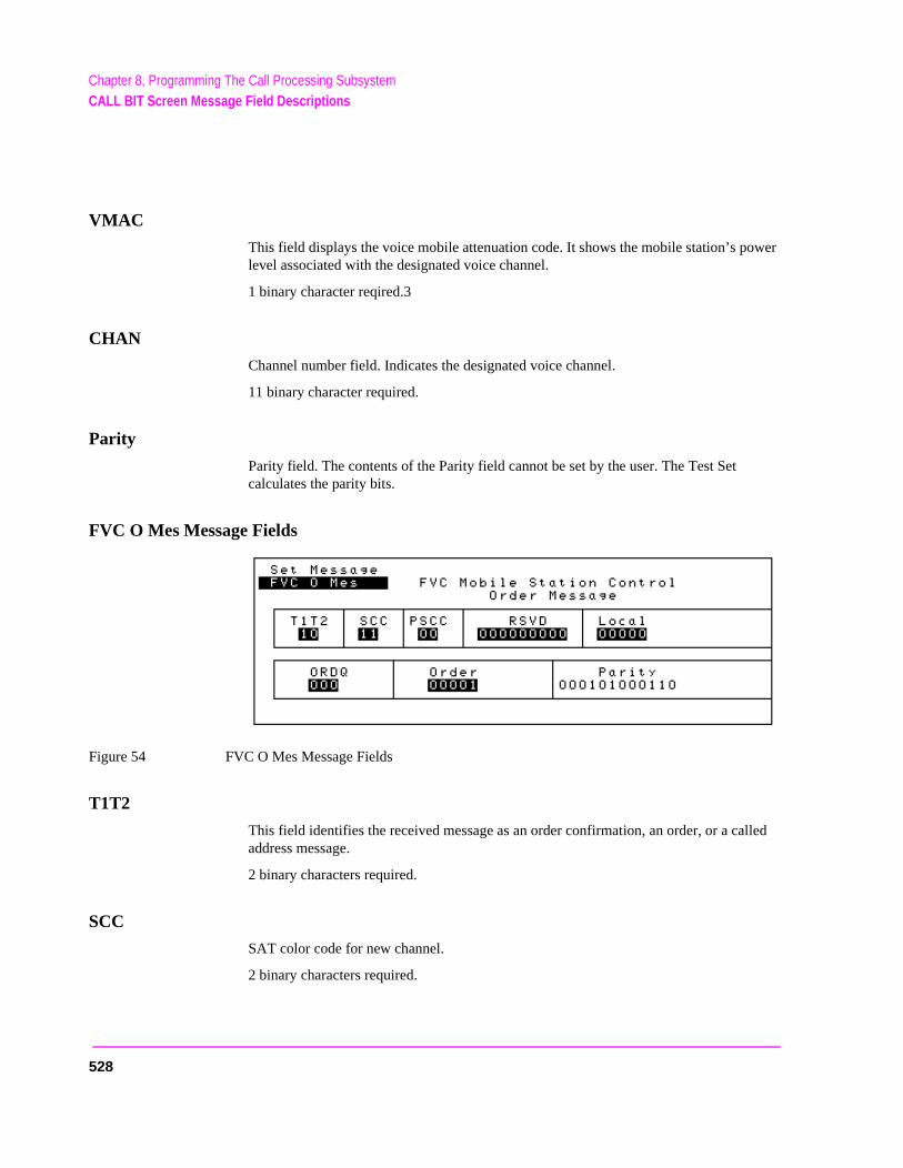
Chapter 8, Programming The Call Processing SubsystemCALL BIT Screen Message Field Descriptions
wer
lled
VMAC
This field displays the voice mobile attenuation code. It shows the mobile station’s polevel associated with the designated voice channel.
1 binary character reqired.3
CHAN
Channel number field. Indicates the designated voice channel.
11 binary character required.
Parity
Parity field. The contents of the Parity field cannot be set by the user. The Test Set calculates the parity bits.
FVC O Mes Message Fields
Figure 54 FVC O Mes Message Fields
T1T2
This field identifies the received message as an order confirmation, an order, or a caaddress message.
2 binary characters required.
SCC
SAT color code for new channel.
2 binary characters required.
528
Chapter 8, Programming The Call Processing SubsystemCALL BIT Screen Message Field Descriptions
PSCC
Present SAT color code. Indicates the SAT color code associated with the present channel.
2 binary characters required.
RSVD
Reserved for future use, all bits must be set as indicated.
9 binary character required.
LOCAL
Local control field. This field is specific to each system. The ORDER field must be set to local control for this field to be interpreted.
5 binary character required.
ORDQ
Order qualifier field. Qualifies the order to a specific action.
3 binary character required.
ORDER
Order field. Identifies the order type.
5 binary character required.
Parity
Parity field. The contents of the Parity field cannot be set by the user. The Test Set calculates the parity bits.
529
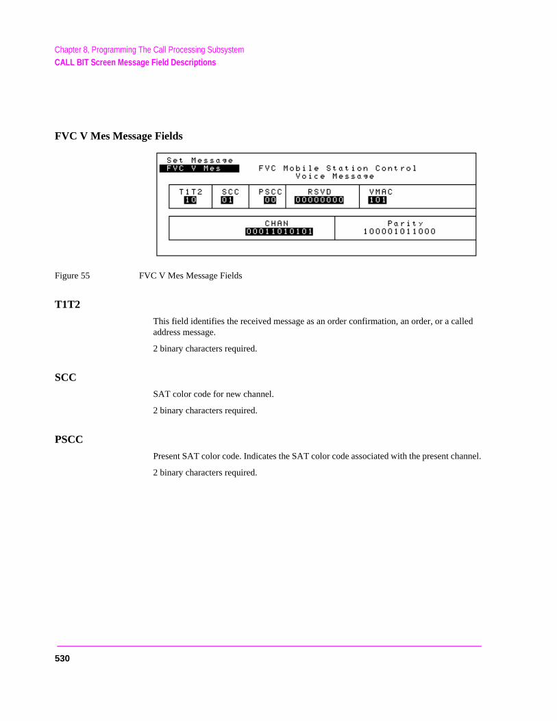
Chapter 8, Programming The Call Processing SubsystemCALL BIT Screen Message Field Descriptions
FVC V Mes Message Fields
Figure 55 FVC V Mes Message Fields
T1T2
This field identifies the received message as an order confirmation, an order, or a called address message.
2 binary characters required.
SCC
SAT color code for new channel.
2 binary characters required.
PSCC
Present SAT color code. Indicates the SAT color code associated with the present channel.
2 binary characters required.
530
Chapter 8, Programming The Call Processing SubsystemCALL BIT Screen Message Field Descriptions
RSVD
Reserved for future use, all bits must be set as indicated.
8 binary character required.
VMAC
This field displays the voice mobile attenuation code. It shows the mobile station power level associated with the designated voice channel.
3 binary character required.
CHAN
Channel number field. Indicates the designated voice channel.
11 binary character required.
Parity
Parity field. The contents of the Parity field cannot be set by the user. The Test Set calculates the parity bits.
531
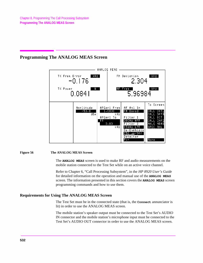
Chapter 8, Programming The Call Processing SubsystemProgramming The ANALOG MEAS Screen
DIO the .
Programming The ANALOG MEAS Screen
Figure 56 The ANALOG MEAS Screen
The ANALOG MEAS screen is used to make RF and audio measurements on the mobile station connected to the Test Set while on an active voice channel.
Refer to Chapter 6, “Call Processing Subsystem”, in the HP 8920 User’s Guide for detailed information on the operation and manual use of the ANALOG MEAS screen. The information presented in this section covers the ANALOG MEAS screen programming commands and how to use them.
Requirements for Using The ANALOG MEAS Screen
The Test Set must be in the connected state (that is, the Connect annunciator is lit) in order to use the ANALOG MEAS screen.
The mobile station’s speaker output must be connected to the Test Set’s AUIN connector and the mobile station’s microphone input must be connected toTest Set’s AUDIO OUT connector in order to use the ANALOG MEAS screen
532
Chapter 8, Programming The Call Processing SubsystemProgramming The ANALOG MEAS Screen
hilerrorEAS
To ts use
.
Refer to "Connecting a Mobile Station to the Test Set" on page 449 for connection information. If the mobile station does not have audio connections the ANALOG MEAS screen cannot be used.
CAUTION: The host firmware does not monitor the mobile station’s transmitted carrier power wthe ANALOG MEAS screen is displayed. If the power falls below 0.0005 Watts no emessage is displayed nor will the Test Set terminate the call while on the ANALOG Mscreen.
How To Program The ANALOG MEAS Screen
The ANALOG MEAS screen combines some of the Test Set’s Audio Analyzer fields and some of the Test Set’s RF Generator fields onto one screen for the purpose of testing the audio characteristics of the mobile station.
Only those fields which are pertinent to testing the mobile station’s audio characteristics have been combined onto the ANALOG MEAS screen.
Since the fields on the ANALOG MEAS screen are imported from other screens those fields are programmed exactly as they would be on their home screen.set up the fields, program the appropriate instrument. To make measurementhe MEASure subsystem.
AF Anl In
This field selects the input for the Audio Frequency analyzer. See "AF Analyzer," in chapter , on page 101 for programming command syntax.
AF Freq
This field is a one-of-many field used to select the type of measurement to bemade by the Audio Frequency Analyzer on the audio signal being measuredSee "Measure," in chapter , on page 151 for programming command syntax.
AFGen1 Freq
This field sets the output frequency of Audio Frequency Generator #1. See "AF Analyzer," in chapter , on page 101 for programming command syntax.
533
Chapter 8, Programming The Call Processing SubsystemProgramming The ANALOG MEAS Screen
put
used
e of
hich
AFGen1 To
This field has two subfields:
• the upper subfield sets the destination port for Audio Frequency Generator #1 • FM = RF Generator FM modulator • AM = RF Generator AM modulator• Audio Out = AUDIO OUT connector on front panel of Test Set
• the lower subfield sets the:• FM modulation deviation if upper subfield set to FM • AM modulation depth if upper subfield set to AM• amplitude of audio signal (volts RMS) at the AUDIO OUT connector if upper sub-
field set to Audio Out
For testing mobile stations the upper field is normally set to FM and the lower field set to the desired FM deviation in kHz. See "AF Generator 1," in chapter , on page 104 for programming command syntax.
Amplitude
This field sets the output power of the Test Sets’s transmitter (that is, the outpower of the Test Set’s RF Generator). See "RF Generator," in chapter , on page 167 for programming command syntax.
De-Emphasis
This field is used to select or bypass the 750 uSec de-emphasis filter networkto condition the audio signal before being analyzed by the Audio Frequency Analyzer. See "AF Analyzer," in chapter , on page 101 for programming command syntax.
Detector
This field is used to select the type of detector used to measure the amplitudthe audio signal being analyzed by the Audio Frequency Analyzer. See "AF Analyzer," in chapter , on page 101 for programming command syntax.
Filter 1
This field selects one of several standard or optional audio frequency filters wcan be used to condition the audio signal before being analyzed by the AudioFrequency Analyzer.See "AF Analyzer," in chapter , on page 101 for programming command syntax.
534
Chapter 8, Programming The Call Processing SubsystemProgramming The ANALOG MEAS Screen
Filter 2
This field selects one of several standard or optional audio frequency filters which can be used to condition the audio signal before being analyzed by the Audio Frequency Analyzer. See "AF Analyzer," in chapter , on page 101 for programming command syntax.
FM Deviation
This field displays the measured FM deviation of the carrier being transmitted by the mobile station. Four dashes (----) indicate that no carrier is present to measure. See "Measure," in chapter , on page 151 for programming command syntax.
TX Freq Error
This field displays the frequency error (error = assigned carrier frequency - measured carrier frequency) of the carrier being transmitted by the mobile station. Four dashes (----) indicates that there is no carrier frequency present to measure. See "Measure," in chapter , on page 151 for programming command syntax.
TX Power
This field displays the measured RF power of the carrier being transmitted by the mobile station. Four dashes (----) indicates that there is no carrier present to measure. See "Measure," in chapter , on page 151 for programming command syntax.
Example Measurement Routines
There are a wide variety of audio measurements which can be made from the ANALOG MEAS screen.
The following examples illustrate how to make a typical mobile station receiver measurement (RF Sensitivity) and a typical mobile station transmitter measurement (FM Hum and Noise).
Refer to the HP 8920A RF Communications Test Set Applications Handbook, section “Testing FM Radios” for further information on using the Test Set’s Audio Analyzer to make audio measurements.
535
Chapter 8, Programming The Call Processing SubsystemProgramming The ANALOG MEAS Screen
ector
Example RF Sensitivity Measurement
The following example code segment shows how to program the ANALOG MEAS screen to make an RF Sensitivity measurement. The code segment represents a HP RM BASIC subprogram.
In order for this subprogram to work properly the following conditions must be true when the subroutine is called:
• Call Processing Subsystem is in the Connect state (that is, the Connect annunciator is lit)
• the mobile station’s speaker output is connected to the Test Set’s AUDIO IN conn• the mobile station’s microphone input must be connected to the Test Set’s AUDIO
OUT connector
The intended purpose of this example subprogram is to illustrate how to program the ANALOG MEAS screen. There are a variety of ways to make an RF Sensitivity measurement. The method used in this example is based upon the EIA/IS-19-B Standard (May 1988). The method and standard chosen for any particular application will depend upon the mobile station being tested.
536
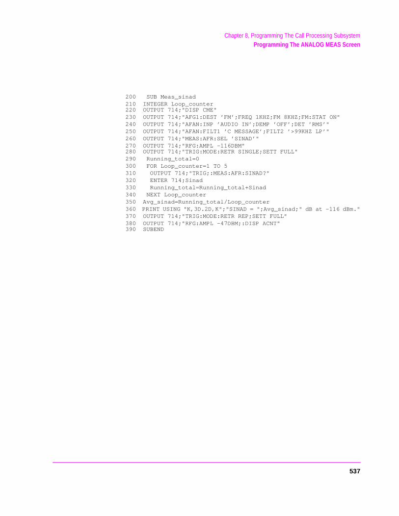
Chapter 8, Programming The Call Processing SubsystemProgramming The ANALOG MEAS Screen
200 SUB Meas_sinad210 INTEGER Loop_counter220 OUTPUT 714;"DISP CME"230 OUTPUT 714;"AFG1:DEST ’FM’;FREQ 1KHZ;FM 8KHZ;FM:STAT ON"240 OUTPUT 714;"AFAN:INP ’AUDIO IN’;DEMP ’OFF’;DET ’RMS’"250 OUTPUT 714;"AFAN:FILT1 ’C MESSAGE’;FILT2 ’>99KHZ LP’"260 OUTPUT 714;"MEAS:AFR:SEL ’SINAD’"270 OUTPUT 714;"RFG:AMPL -116DBM"280 OUTPUT 714;"TRIG:MODE:RETR SINGLE;SETT FULL"290 Running_total=0300 FOR Loop_counter=1 TO 5310 OUTPUT 714;"TRIG;:MEAS:AFR:SINAD?"320 ENTER 714;Sinad330 Running_total=Running_total+Sinad340 NEXT Loop_counter350 Avg_sinad=Running_total/Loop_counter360 PRINT USING "K,3D.2D,K";"SINAD = ";Avg_sinad;" dB at -116 dBm."370 OUTPUT 714;"TRIG:MODE:RETR REP;SETT FULL"380 OUTPUT 714;"RFG:AMPL -47DBM;:DISP ACNT"390 SUBEND
537
Chapter 8, Programming The Call Processing SubsystemProgramming The ANALOG MEAS Screen
ector
Example FM Hum & Noise Measurement
The following example code segment shows how to program the ANALOG MEAS screen to make an FM Hum & Noise measurement. The code segment represents a HP RM BASIC subprogram.
In order for this subprogram to work properly the following conditions must be true when the subroutine is called:
• Call Processing Subsystem is in the Connect state (that is, the Connect annunciator is lit)
• the mobile station’s speaker output is connected to the Test Set’s AUDIO IN conn• the mobile station’s microphone input must be connected to the Test Set’s AUDIO
OUT connector
The intended purpose of this example subprogram is to illustrate how to program the ANALOG MEAS screen. There are a variety of ways to make an FM Hum & Noise measurement. The method used in this example is based upon the EIA/IS-19-B Standard (May 1988). The method and standard chosen for any particular application will depend upon the mobile station being tested.
538
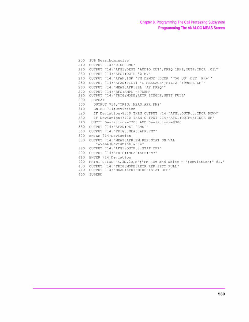
Chapter 8, Programming The Call Processing SubsystemProgramming The ANALOG MEAS Screen
200 SUB Meas_hum_noise210 OUTPUT 714;"DISP CME"220 OUTPUT 714;"AFG1:DEST ’AUDIO OUT’;FREQ 1KHZ;OUTP:INCR .01V"230 OUTPUT 714;"AFG1:OUTP 50 MV"240 OUTPUT 714;"AFAN:INP ’FM DEMOD’;DEMP ’750 US’;DET ’PK+’"250 OUTPUT 714;"AFAN:FILT1 ’C MESSAGE’;FILT2 ’>99KHZ LP’"260 OUTPUT 714;"MEAS:AFR:SEL ’AF FREQ’"270 OUTPUT 714;"RFG:AMPL -47DBM"280 OUTPUT 714;"TRIG:MODE:RETR SINGLE;SETT FULL"290 REPEAT300 OUTPUT 714;"TRIG;:MEAS:AFR:FM?"310 ENTER 714;Deviation320 IF Deviation>8300 THEN OUTPUT 714;"AFG1:OUTPut:INCR DOWN"330 IF Deviation<7700 THEN OUTPUT 714;"AFG1:OUTPut:INCR UP"340 UNTIL Deviation>=7700 AND Deviation<=8300350 OUTPUT 714;"AFAN:DET ’RMS’"360 OUTPUT 714;"TRIG;:MEAS:AFR:FM?"370 ENTER 714;Deviation380 OUTPUT 714;"MEAS:AFR:FM:REF:STAT ON;VAL
"&VAL$(Deviation)&"HZ"390 OUTPUT 714;"AFG1:OUTPut:STAT OFF"400 OUTPUT 714;"TRIG;:MEAS:AFR:FM?"410 ENTER 714;Deviation420 PRINT USING "K,3D.2D,K";"FM Hum and Noise = ";Deviation;" dB."430 OUTPUT 714;"TRIG:MODE:RETR REP;SETT FULL"440 OUTPUT 714;"MEAS:AFR:FM:REF:STAT OFF"450 SUBEND
539
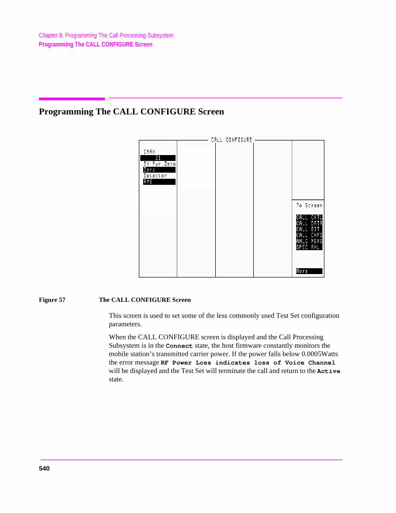
Chapter 8, Programming The Call Processing SubsystemProgramming The CALL CONFIGURE Screen
tts
Programming The CALL CONFIGURE Screen
Figure 57 The CALL CONFIGURE Screen
This screen is used to set some of the less commonly used Test Set configuration parameters.
When the CALL CONFIGURE screen is displayed and the Call Processing Subsystem is in the Connect state, the host firmware constantly monitors the mobile station’s transmitted carrier power. If the power falls below 0.0005Wathe error message RF Power Loss indicates loss of Voice Channel will be displayed and the Test Set will terminate the call and return to the Active state.
540
Chapter 8, Programming The Call Processing SubsystemProgramming The CALL CONFIGURE Screen
uld beter can
NOTE: In order to ensure that the host firmware makes the correct decisions regarding thepresence of the mobile stations’s RF carrier, the Test Set’s RF power meter shozeroed before using the Call Processing Subsystem. Failure to zero the power meresult in erroneous RF power measurements. See "Conditioning the Test Set for CallProcessing" on page 452 for information on zeroing the RF Power meter manually.
Refer to “Using the Analog Call Processing Subsystem” in the Application Guide for operating information on the use of the CALL CONFIGURE screen.
Refer to Chapter 6, “Call Processing Subsystem”, in the HP 8920 User’s Guide for detailed information on the operation and manual use of the CALL CONFIGURE screen.
The information presented in this section covers the CALL CONFIGURE screen programming commands and how to use them.
CMAX
The CMAX field sets the number of access channels in the system. This will determine how many channels must be scanned by the mobile station when trying to access the Test Set. The value of this field will affect the time required for the mobile station to connect with the Test Set.
The :CMAXimum command is used to control this field.
The CMAX field is an immediate action field. That is, whenever the :CMAXimum command is sent, the change is reflected immediately in the appropriate signaling message(s) being sent on the forward control channel. No change occurs to the current state (i.e. Active, Register, Page, Access, Connect) of the Call Processing Subsystem.
The query form of the command (that is, :CMAXimum?) can be used to determine the current control channel setting.
Syntax
:CMAXimum <integer number>:CMAXimum?
Example
OUTPUT 714;"CALLP:CMAX 21"OUTPUT 714;"CALLP:CMAX?"ENTER 714;Num_acc_chans
541
Chapter 8, Programming The Call Processing SubsystemProgramming The CALL CONFIGURE Screen
Detector
This field is used to select the type of detector used to measure the amplitude of the audio signal being analyzed on the ANALOG MEAS screen. The Detector field is imported from the AF ANALYZER screen and is programmed exactly as it is on its home screen. See "AF Analyzer" on page 101 for programming command syntax.
TX Pwr Zero
The TX Pwr Zero function establishes a 0.0000 W reference for measuring RF power at the RF IN/OUT port. The TX Pwr Zero field is imported from the RF ANALYZER screen and is programmed exactly as it is on its home screen. See "RF Analyzer" on page 165 for programming command syntax.
RF power must not be applied while zeroing the power meter.
542
Chapter 8, Programming The Call Processing SubsystemExample Programs
in
he
s:
ation
Example Programs
This section contains two example programs for controlling the Call Processing Subsystem. The SRQ Example Program demonstrates how to control program flow using the service request feature of the HP-IB. The Polling Example Program demonstrates how to control program flow by polling the Test Set’sstatus registers.
The programs can be run on an external controller or on the Test Set’s built-IBASIC Controller. If the programs are run on the Test Set’s built-in IBASIC Controller bus addresses and time-out values must be changed as noted in tprograms.
Both example programs have the same basic structure and execute as follow
StartInitialize program variablesConfigure the Test Set’s status registers for service request or pollingCondition the Test Set for Call ProcessingConfigure the Test SetSet the Active stateRegister the mobile station and print the registration dataPage the mobile stationMeasure several parameters of the mobile station’s carrier and print resultsOrder the mobile station to change power and print the mobile station order verificConfigure the Test Set for a handoffHandoff the mobile station to a new channelPut the mobile station into the maintenance modeSend an alert order to the mobile station to take it out of maintenance modeRelease the mobile stationPrompt the operator to originate a call from the mobile stationPrint the origination data from the mobile stationRelease the mobile stationEnd
543

Chapter 8, Programming The Call Processing SubsystemExample Programs
.
The program traps any errors which may occur while executing. If an error is detected, the error data is printed and the program stops. In a ‘real world’ environment the controlprogram would have to make some flow decision based upon the nature of the error
Following each program is a Comments section which contains relevant comments regarding individual program lines.
The example program uses function calls to set the various call processing states and to send orders to the mobile station. Function calls are not the only programming construct which can be used to control the Call Processing Subsystem. The example programs were designed to illustrate how to use the Call Processing Subsystem in a simple, straightforward manner. The program structure and program constructs used in your application will depend upon the programming language used and the requirements of your application.
544
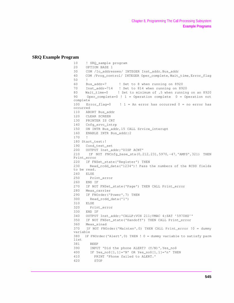
Chapter 8, Programming The Call Processing SubsystemExample Programs
SRQ Example Program10 ! SRQ_sample program20 OPTION BASE 130 COM /Io_addresses/ INTEGER Inst_addr,Bus_addr40 COM /Prog_control/ INTEGER Oper_complete,Wait_time,Error_flag50 !60 Bus_addr=7 ! Set to 8 when running on 892070 Inst_addr=714 ! Set to 814 when running on 892080 Wait_time=0 ! Set to minimum of .5 when running on an 892090 Oper_complete=0 ! 1 = Operation complete 0 = Operation notcomplete100 Error_flag=0 ! 1 = An error has occurred 0 = no error hasoccurred110 ABORT Bus_addr120 CLEAR SCREEN130 PRINTER IS CRT140 Cnfg_srvc_intrp150 ON INTR Bus_addr,15 CALL Srvice_interupt160 ENABLE INTR Bus_addr;2170 !180 Start_test:!190 Cond_test_set200 OUTPUT Inst_addr;"DISP ACNT"210 IF NOT FNCnfg_base_sta(0,212,231,5970,-47,"AMPS",321) THENPrint_error220 IF FNSet_state("Register") THEN230 Read_rcdd_data("1234")! Pass the numbers of the RCDD fieldsto be read.240 ELSE250 Print_error260 END IF270 IF NOT FNSet_state("Page") THEN CALL Print_error280 Meas_carrier290 IF FNOrder("Power",7) THEN300 Read_rcdd_data("1")310 ELSE320 Print_error330 END IF340 OUTPUT Inst_addr;"CALLP:VCH 211;VMAC 4;SAT ’5970HZ’"350 IF NOT FNSet_state("Handoff") THEN CALL Print_error360 Meas_sinad370 IF NOT FNOrder("Mainten",0) THEN CALL Print_error !0 = dummyvariable380 IF FNOrder("Alert",0) THEN ! 0 = dummy variable to satisfy parmlist381 BEEP390 INPUT "Did the phone ALERT? (Y/N)",Yes_no$400 IF Yes_no$[1,1]="N" OR Yes_no$[1,1]="n" THEN410 PRINT "Phone failed to ALERT."420 STOP
545
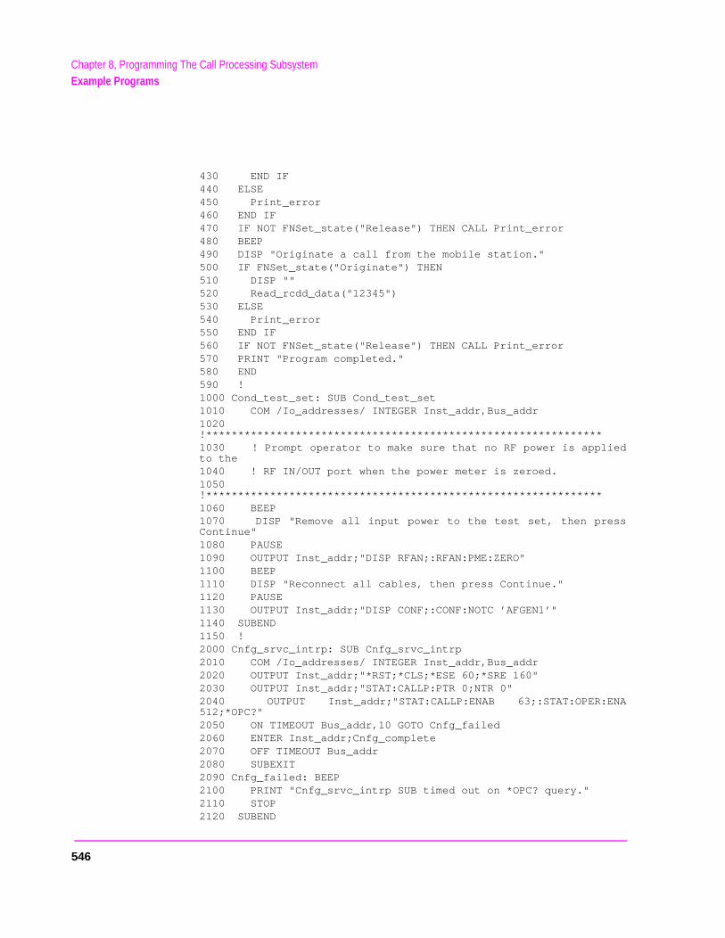
Chapter 8, Programming The Call Processing SubsystemExample Programs
430 END IF440 ELSE450 Print_error460 END IF470 IF NOT FNSet_state("Release") THEN CALL Print_error480 BEEP490 DISP "Originate a call from the mobile station."500 IF FNSet_state("Originate") THEN510 DISP ""520 Read_rcdd_data("12345")530 ELSE540 Print_error550 END IF560 IF NOT FNSet_state("Release") THEN CALL Print_error570 PRINT "Program completed."580 END590 !1000 Cond_test_set: SUB Cond_test_set1010 COM /Io_addresses/ INTEGER Inst_addr,Bus_addr1020!**************************************************************1030 ! Prompt operator to make sure that no RF power is appliedto the1040 ! RF IN/OUT port when the power meter is zeroed.1050!**************************************************************1060 BEEP1070 DISP "Remove all input power to the test set, then pressContinue"1080 PAUSE1090 OUTPUT Inst_addr;"DISP RFAN;:RFAN:PME:ZERO"1100 BEEP1110 DISP "Reconnect all cables, then press Continue."1120 PAUSE1130 OUTPUT Inst_addr;"DISP CONF;:CONF:NOTC ’AFGEN1’"1140 SUBEND1150 !2000 Cnfg_srvc_intrp: SUB Cnfg_srvc_intrp2010 COM /Io_addresses/ INTEGER Inst_addr,Bus_addr2020 OUTPUT Inst_addr;"*RST;*CLS;*ESE 60;*SRE 160"2030 OUTPUT Inst_addr;"STAT:CALLP:PTR 0;NTR 0"2040 OUTPUT Inst_addr;"STAT:CALLP:ENAB 63;:STAT:OPER:ENA512;*OPC?"2050 ON TIMEOUT Bus_addr,10 GOTO Cnfg_failed2060 ENTER Inst_addr;Cnfg_complete2070 OFF TIMEOUT Bus_addr2080 SUBEXIT2090 Cnfg_failed: BEEP2100 PRINT "Cnfg_srvc_intrp SUB timed out on *OPC? query."2110 STOP2120 SUBEND
546
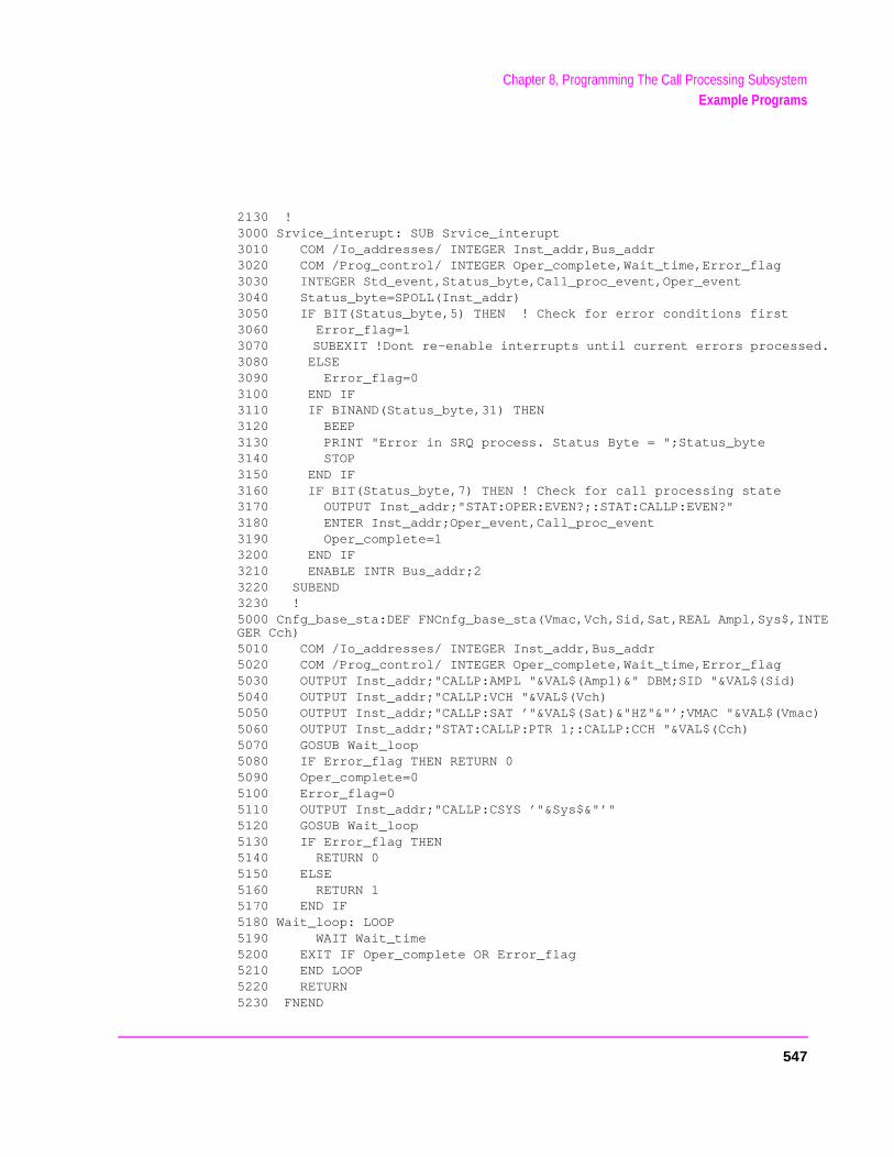
Chapter 8, Programming The Call Processing SubsystemExample Programs
2130 !3000 Srvice_interupt: SUB Srvice_interupt3010 COM /Io_addresses/ INTEGER Inst_addr,Bus_addr3020 COM /Prog_control/ INTEGER Oper_complete,Wait_time,Error_flag3030 INTEGER Std_event,Status_byte,Call_proc_event,Oper_event3040 Status_byte=SPOLL(Inst_addr)3050 IF BIT(Status_byte,5) THEN ! Check for error conditions first3060 Error_flag=13070 SUBEXIT !Dont re-enable interrupts until current errors processed.3080 ELSE3090 Error_flag=03100 END IF3110 IF BINAND(Status_byte,31) THEN3120 BEEP3130 PRINT "Error in SRQ process. Status Byte = ";Status_byte3140 STOP3150 END IF3160 IF BIT(Status_byte,7) THEN ! Check for call processing state3170 OUTPUT Inst_addr;"STAT:OPER:EVEN?;:STAT:CALLP:EVEN?"3180 ENTER Inst_addr;Oper_event,Call_proc_event3190 Oper_complete=13200 END IF3210 ENABLE INTR Bus_addr;23220 SUBEND3230 !5000 Cnfg_base_sta:DEF FNCnfg_base_sta(Vmac,Vch,Sid,Sat,REAL Ampl,Sys$,INTEGER Cch)5010 COM /Io_addresses/ INTEGER Inst_addr,Bus_addr5020 COM /Prog_control/ INTEGER Oper_complete,Wait_time,Error_flag5030 OUTPUT Inst_addr;"CALLP:AMPL "&VAL$(Ampl)&" DBM;SID "&VAL$(Sid)5040 OUTPUT Inst_addr;"CALLP:VCH "&VAL$(Vch)5050 OUTPUT Inst_addr;"CALLP:SAT ’"&VAL$(Sat)&"HZ"&"’;VMAC "&VAL$(Vmac)5060 OUTPUT Inst_addr;"STAT:CALLP:PTR 1;:CALLP:CCH "&VAL$(Cch)5070 GOSUB Wait_loop5080 IF Error_flag THEN RETURN 05090 Oper_complete=05100 Error_flag=05110 OUTPUT Inst_addr;"CALLP:CSYS ’"&Sys$&"’"5120 GOSUB Wait_loop5130 IF Error_flag THEN5140 RETURN 05150 ELSE5160 RETURN 15170 END IF5180 Wait_loop: LOOP5190 WAIT Wait_time5200 EXIT IF Oper_complete OR Error_flag5210 END LOOP5220 RETURN5230 FNEND
547
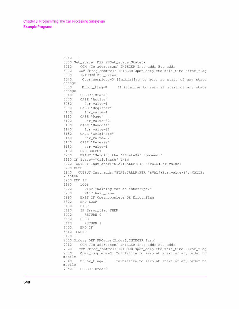
Chapter 8, Programming The Call Processing SubsystemExample Programs
5240 !6000 Set_state: DEF FNSet_state(State$)6010 COM /Io_addresses/ INTEGER Inst_addr,Bus_addr6020 COM /Prog_control/ INTEGER Oper_complete,Wait_time,Error_flag6030 INTEGER Ptr_value6040 Oper_complete=0 !Initialize to zero at start of any statechange6050 Error_flag=0 !Initialize to zero at start of any statechange6060 SELECT State$6070 CASE "Active"6080 Ptr_value=16090 CASE "Register"6100 Ptr_value=16110 CASE "Page"6120 Ptr_value=326130 CASE "Handoff"6140 Ptr_value=326150 CASE "Originate"6160 Ptr_value=326170 CASE "Release"6180 Ptr_value=16190 END SELECT6200 PRINT "Sending the "&State$&" command."6210 IF State$="Originate" THEN6220 OUTPUT Inst_addr;"STAT:CALLP:PTR "&VAL$(Ptr_value)6230 ELSE6240 OUTPUT Inst_addr;"STAT:CALLP:PTR "&VAL$(Ptr_value)&";:CALLP:&State$6250 END IF6260 LOOP6270 DISP "Waiting for an interrupt."6280 WAIT Wait_time6290 EXIT IF Oper_complete OR Error_flag6300 END LOOP6400 DISP6410 IF Error_flag THEN6420 RETURN 06430 ELSE6440 RETURN 16450 END IF6460 FNEND6470 !7000 Order: DEF FNOrder(Order$,INTEGER Parm)7010 COM /Io_addresses/ INTEGER Inst_addr,Bus_addr7020 COM /Prog_control/ INTEGER Oper_complete,Wait_time,Error_flag7030 Oper_complete=0 !Initialize to zero at start of any order tomobile7040 Error_flag=0 !Initialize to zero at start of any order tomobile7050 SELECT Order$
548
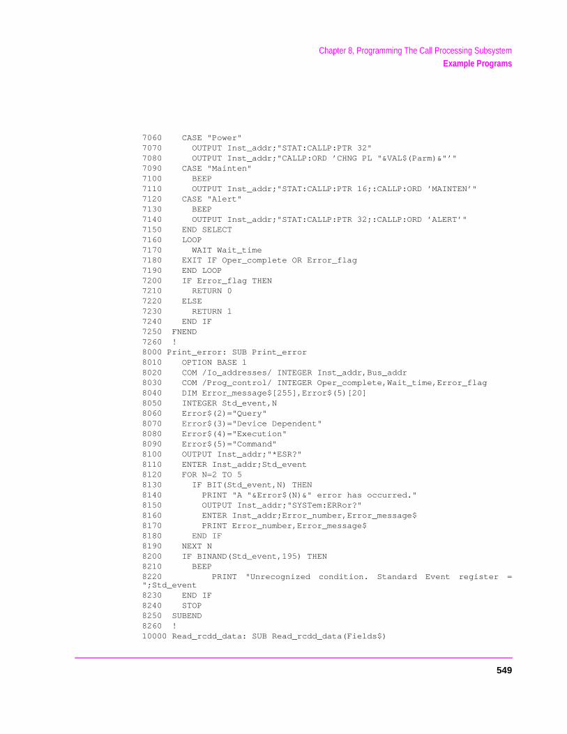
Chapter 8, Programming The Call Processing SubsystemExample Programs
7060 CASE "Power"7070 OUTPUT Inst_addr;"STAT:CALLP:PTR 32"7080 OUTPUT Inst_addr;"CALLP:ORD ’CHNG PL "&VAL$(Parm)&"’"7090 CASE "Mainten"7100 BEEP7110 OUTPUT Inst_addr;"STAT:CALLP:PTR 16;:CALLP:ORD ’MAINTEN’"7120 CASE "Alert"7130 BEEP7140 OUTPUT Inst_addr;"STAT:CALLP:PTR 32;:CALLP:ORD ’ALERT’"7150 END SELECT7160 LOOP7170 WAIT Wait_time7180 EXIT IF Oper_complete OR Error_flag7190 END LOOP7200 IF Error_flag THEN7210 RETURN 07220 ELSE7230 RETURN 17240 END IF7250 FNEND7260 !8000 Print_error: SUB Print_error8010 OPTION BASE 18020 COM /Io_addresses/ INTEGER Inst_addr,Bus_addr8030 COM /Prog_control/ INTEGER Oper_complete,Wait_time,Error_flag8040 DIM Error_message$[255],Error$(5)[20]8050 INTEGER Std_event,N8060 Error$(2)="Query"8070 Error$(3)="Device Dependent"8080 Error$(4)="Execution"8090 Error$(5)="Command"8100 OUTPUT Inst_addr;"*ESR?"8110 ENTER Inst_addr;Std_event8120 FOR N=2 TO 58130 IF BIT(Std_event,N) THEN8140 PRINT "A "&Error$(N)&" error has occurred."8150 OUTPUT Inst_addr;"SYSTem:ERRor?"8160 ENTER Inst_addr;Error_number,Error_message$8170 PRINT Error_number,Error_message$8180 END IF8190 NEXT N8200 IF BINAND(Std_event,195) THEN8210 BEEP8220 PRINT "Unrecognized condition. Standard Event register =";Std_event8230 END IF8240 STOP8250 SUBEND8260 !10000 Read_rcdd_data: SUB Read_rcdd_data(Fields$)
549
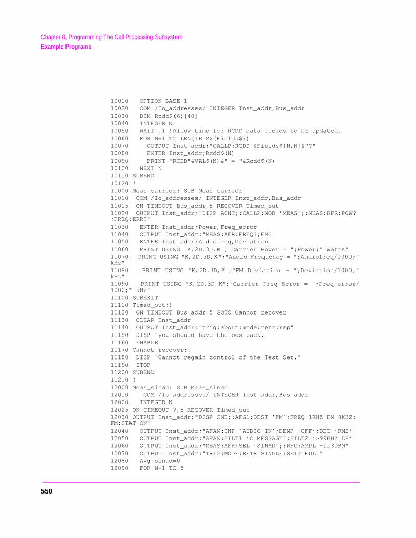
Chapter 8, Programming The Call Processing SubsystemExample Programs
10010 OPTION BASE 110020 COM /Io_addresses/ INTEGER Inst_addr,Bus_addr10030 DIM Rcdd$(6)[40]10040 INTEGER N10050 WAIT .1 !Allow time for RCDD data fields to be updated.10060 FOR N=1 TO LEN(TRIM$(Fields$))10070 OUTPUT Inst_addr;"CALLP:RCDD"&Fields$[N,N]&"?"10080 ENTER Inst_addr;Rcdd$(N)10090 PRINT "RCDD"&VAL$(N)&" = "&Rcdd$(N)10100 NEXT N10110 SUBEND10120 !11000 Meas_carrier: SUB Meas_carrier11010 COM /Io_addresses/ INTEGER Inst_addr,Bus_addr11015 ON TIMEOUT Bus_addr,5 RECOVER Timed_out11020 OUTPUT Inst_addr;"DISP ACNT;:CALLP:MOD ’MEAS’;:MEAS:RFR:POW?;FREQ:ERR?"11030 ENTER Inst_addr;Power,Freq_error11040 OUTPUT Inst_addr;"MEAS:AFR:FREQ?;FM?"11050 ENTER Inst_addr;Audiofreq,Deviation11060 PRINT USING "K,2D.3D,K";"Carrier Power = ";Power;" Watts"11070 PRINT USING "K,2D.3D,K";"Audio Frequency = ";Audiofreq/1000;"kHz"11080 PRINT USING "K,2D.3D,K";"FM Deviation = ";Deviation/1000;"kHz"11090 PRINT USING "K,2D.3D,K";"Carrier Freq Error = ";Freq_error/1000;" kHz"11100 SUBEXIT11110 Timed_out:!11120 ON TIMEOUT Bus_addr,5 GOTO Cannot_recover11130 CLEAR Inst_addr11140 OUTPUT Inst_addr;"trig:abort;mode:retr:rep"11150 DISP "you should have the box back."11160 ENABLE11170 Cannot_recover:!11180 DISP "Cannot regain control of the Test Set."11190 STOP11200 SUBEND11210 !12000 Meas_sinad: SUB Meas_sinad12010 COM /Io_addresses/ INTEGER Inst_addr,Bus_addr12020 INTEGER N12025 ON TIMEOUT 7,5 RECOVER Timed_out12030 OUTPUT Inst_addr;"DISP CME;:AFG1:DEST ’FM’;FREQ 1KHZ FM 8KHZ;FM:STAT ON"12040 OUTPUT Inst_addr;"AFAN:INP ’AUDIO IN’;DEMP ’OFF’;DET ’RMS’"12050 OUTPUT Inst_addr;"AFAN:FILT1 ’C MESSAGE’;FILT2 ’>99KHZ LP’"12060 OUTPUT Inst_addr;"MEAS:AFR:SEL ’SINAD’;:RFG:AMPL -113DBM"12070 OUTPUT Inst_addr;"TRIG:MODE:RETR SINGLE;SETT FULL"12080 Avg_sinad=012090 FOR N=1 TO 5
550
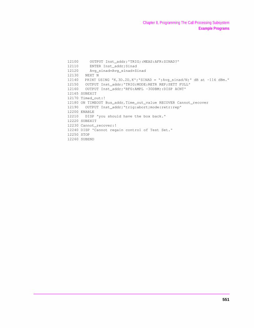
Chapter 8, Programming The Call Processing SubsystemExample Programs
12100 OUTPUT Inst_addr;"TRIG;:MEAS:AFR:SINAD?"12110 ENTER Inst_addr;Sinad12120 Avg_sinad=Avg_sinad+Sinad12130 NEXT N12140 PRINT USING "K,3D.2D,K";"SINAD = ";Avg_sinad/N;" dB at -116 dBm."12150 OUTPUT Inst_addr;"TRIG:MODE:RETR REP;SETT FULL"12160 OUTPUT Inst_addr;"RFG:AMPL -30DBM;:DISP ACNT"12165 SUBEXIT12170 Timed_out:!12180 ON TIMEOUT Bus_addr,Time_out_value RECOVER Cannot_recover12190 OUTPUT Inst_addr;"trig:abort;mode:retr:rep"12200 ENABLE12210 DISP "you should have the box back."12220 SUBEXIT12230 Cannot_recover:!12240 DISP "Cannot regain control of Test Set."12250 STOP12260 SUBEND
551
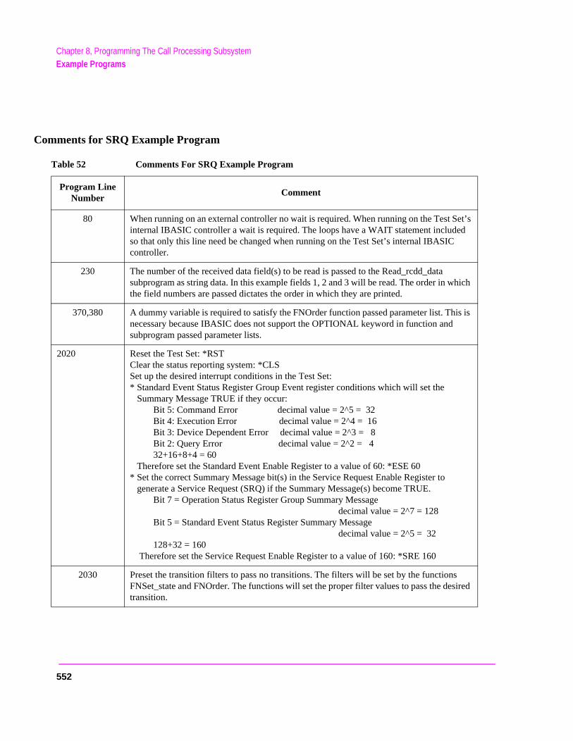
Chapter 8, Programming The Call Processing SubsystemExample Programs
Comments for SRQ Example Program
Table 52 Comments For SRQ Example Program
Program Line Number
Comment
80 When running on an external controller no wait is required. When running on the Test Set’s internal IBASIC controller a wait is required. The loops have a WAIT statement included so that only this line need be changed when running on the Test Set’s internal IBASIC controller.
230 The number of the received data field(s) to be read is passed to the Read_rcdd_data subprogram as string data. In this example fields 1, 2 and 3 will be read. The order in whichthe field numbers are passed dictates the order in which they are printed.
370,380 A dummy variable is required to satisfy the FNOrder function passed parameter list. This isnecessary because IBASIC does not support the OPTIONAL keyword in function and subprogram passed parameter lists.
2020 Reset the Test Set: *RSTClear the status reporting system: *CLSSet up the desired interrupt conditions in the Test Set:* Standard Event Status Register Group Event register conditions which will set the
Summary Message TRUE if they occur:Bit 5: Command Error decimal value = 2^5 = 32Bit 4: Execution Error decimal value = 2^4 = 16Bit 3: Device Dependent Error decimal value = 2^3 = 8Bit 2: Query Error decimal value = 2^2 = 432+16+8+4 = 60
Therefore set the Standard Event Enable Register to a value of 60: *ESE 60* Set the correct Summary Message bit(s) in the Service Request Enable Register to
generate a Service Request (SRQ) if the Summary Message(s) become TRUE.Bit 7 = Operation Status Register Group Summary Message
decimal value = 2^7 = 128Bit 5 = Standard Event Status Register Summary Message
decimal value = 2^5 = 32128+32 = 160
Therefore set the Service Request Enable Register to a value of 160: *SRE 160
2030 Preset the transition filters to pass no transitions. The filters will be set by the functions FNSet_state and FNOrder. The functions will set the proper filter values to pass the desiredtransition.
552
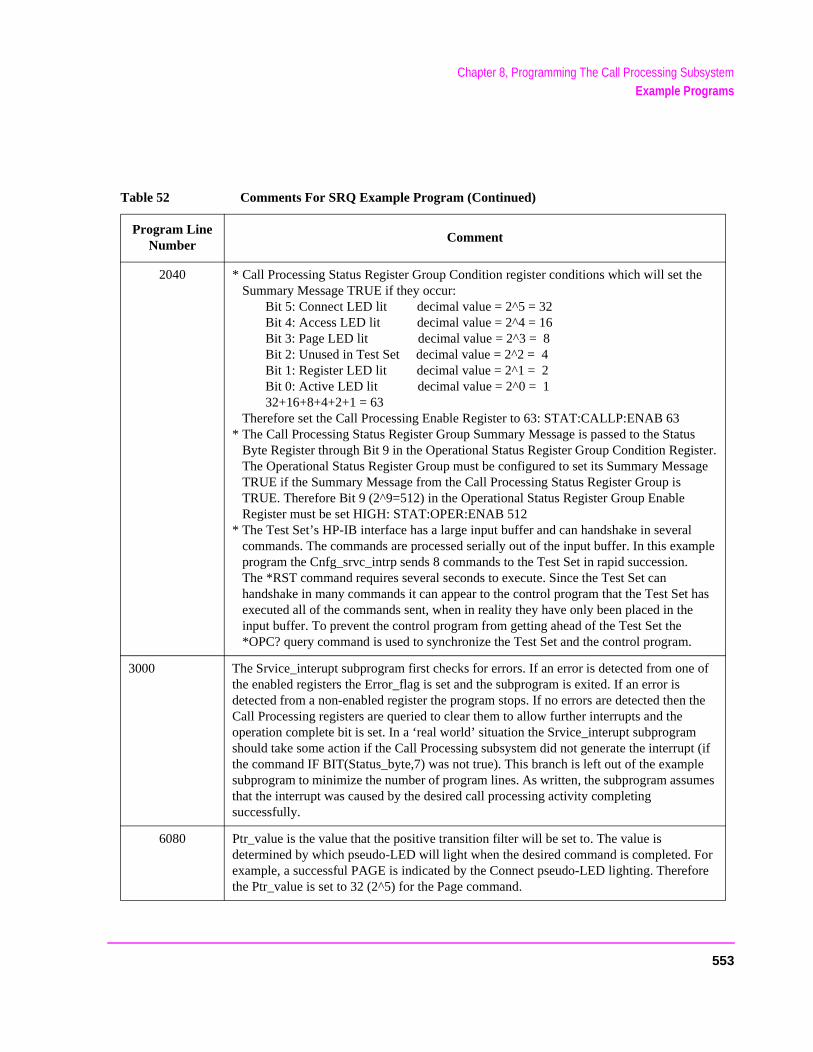
Chapter 8, Programming The Call Processing SubsystemExample Programs
ple
as
f
he
(if es
r e
2040 * Call Processing Status Register Group Condition register conditions which will set theSummary Message TRUE if they occur:
Bit 5: Connect LED lit decimal value = 2^5 = 32Bit 4: Access LED lit decimal value = 2^4 = 16Bit 3: Page LED lit decimal value = 2^3 = 8Bit 2: Unused in Test Set decimal value = 2^2 = 4Bit 1: Register LED lit decimal value = 2^1 = 2Bit 0: Active LED lit decimal value = 2^0 = 132+16+8+4+2+1 = 63
Therefore set the Call Processing Enable Register to 63: STAT:CALLP:ENAB 63* The Call Processing Status Register Group Summary Message is passed to the Status
Byte Register through Bit 9 in the Operational Status Register Group Condition Register.The Operational Status Register Group must be configured to set its Summary MessageTRUE if the Summary Message from the Call Processing Status Register Group isTRUE. Therefore Bit 9 (2^9=512) in the Operational Status Register Group EnableRegister must be set HIGH: STAT:OPER:ENAB 512
* The Test Set’s HP-IB interface has a large input buffer and can handshake in severalcommands. The commands are processed serially out of the input buffer. In this examprogram the Cnfg_srvc_intrp sends 8 commands to the Test Set in rapid succession.The *RST command requires several seconds to execute. Since the Test Set canhandshake in many commands it can appear to the control program that the Test Set hexecuted all of the commands sent, when in reality they have only been placed in theinput buffer. To prevent the control program from getting ahead of the Test Set the*OPC? query command is used to synchronize the Test Set and the control program.
3000 The Srvice_interupt subprogram first checks for errors. If an error is detected from one othe enabled registers the Error_flag is set and the subprogram is exited. If an error is detected from a non-enabled register the program stops. If no errors are detected then tCall Processing registers are queried to clear them to allow further interrupts and the operation complete bit is set. In a ‘real world’ situation the Srvice_interupt subprogram should take some action if the Call Processing subsystem did not generate the interrupt the command IF BIT(Status_byte,7) was not true). This branch is left out of the examplesubprogram to minimize the number of program lines. As written, the subprogram assumthat the interrupt was caused by the desired call processing activity completing successfully.
6080 Ptr_value is the value that the positive transition filter will be set to. The value isdetermined by which pseudo-LED will light when the desired command is completed. Foexample, a successful PAGE is indicated by the Connect pseudo-LED lighting. Thereforthe Ptr_value is set to 32 (2^5) for the Page command.
Table 52 Comments For SRQ Example Program (Continued)
Program Line Number
Comment
553
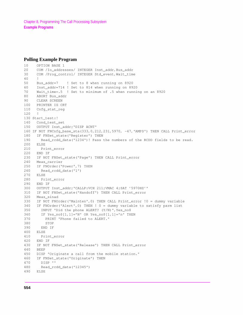
Chapter 8, Programming The Call Processing SubsystemExample Programs
Polling Example Program10 OPTION BASE 120 COM /Io_addresses/ INTEGER Inst_addr,Bus_addr30 COM /Prog_control/ INTEGER Std_event,Wait_time40 !50 Bus_addr=7 ! Set to 8 when running on 892060 Inst_addr=714 ! Set to 814 when running on 892070 Wait_time=.5 ! Set to minimum of .5 when running on an 892080 ABORT Bus_addr90 CLEAR SCREEN100 PRINTER IS CRT110 Cnfg_stat_reg120 !130 Start_test:!140 Cond_test_set150 OUTPUT Inst_addr;"DISP ACNT"160 IF NOT FNCnfg_base_sta(333,0,212,231,5970, -47,"AMPS") THEN CALL Print_error180 IF FNSet_state("Register") THEN190 Read_rcdd_data("1234")! Pass the numbers of the RCDD fields to be read.200 ELSE210 Print_error220 END IF230 IF NOT FNSet_state("Page") THEN CALL Print_error240 Meas_carrier250 IF FNOrder("Power",7) THEN260 Read_rcdd_data("1")270 ELSE280 Print_error290 END IF300 OUTPUT Inst_addr;"CALLP:VCH 211;VMAC 4;SAT ’5970HZ’"310 IF NOT FNSet_state("Handoff") THEN CALL Print_error320 Meas_sinad330 IF NOT FNOrder("Mainten",0) THEN CALL Print_error !0 = dummy variable340 IF FNOrder("Alert",0) THEN ! 0 = dummy variable to satisfy parm list350 INPUT "Did the phone ALERT? (Y/N)",Yes_no$360 IF Yes_no$[1,1]="N" OR Yes_no$[1,1]="n" THEN370 PRINT "Phone failed to ALERT."380 STOP390 END IF400 ELSE410 Print_error420 END IF430 IF NOT FNSet_state("Release") THEN CALL Print_error440 BEEP450 DISP "Originate a call from the mobile station."460 IF FNSet_state("Originate") THEN470 DISP ""480 Read_rcdd_data("12345")490 ELSE
554
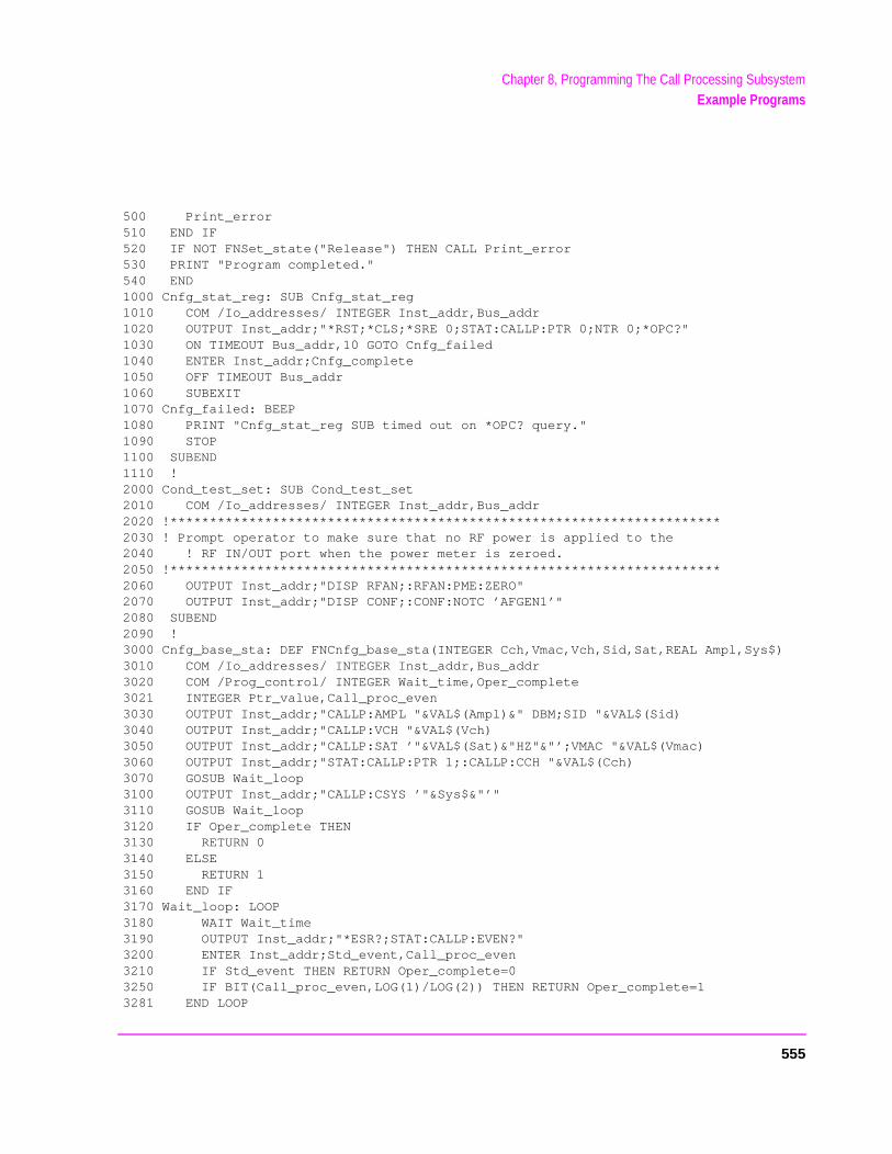
Chapter 8, Programming The Call Processing SubsystemExample Programs
500 Print_error510 END IF520 IF NOT FNSet_state("Release") THEN CALL Print_error530 PRINT "Program completed."540 END1000 Cnfg_stat_reg: SUB Cnfg_stat_reg1010 COM /Io_addresses/ INTEGER Inst_addr,Bus_addr1020 OUTPUT Inst_addr;"*RST;*CLS;*SRE 0;STAT:CALLP:PTR 0;NTR 0;*OPC?"1030 ON TIMEOUT Bus_addr,10 GOTO Cnfg_failed1040 ENTER Inst_addr;Cnfg_complete1050 OFF TIMEOUT Bus_addr1060 SUBEXIT1070 Cnfg_failed: BEEP1080 PRINT "Cnfg_stat_reg SUB timed out on *OPC? query."1090 STOP1100 SUBEND1110 !2000 Cond_test_set: SUB Cond_test_set2010 COM /Io_addresses/ INTEGER Inst_addr,Bus_addr2020 !**********************************************************************2030 ! Prompt operator to make sure that no RF power is applied to the2040 ! RF IN/OUT port when the power meter is zeroed.2050 !**********************************************************************2060 OUTPUT Inst_addr;"DISP RFAN;:RFAN:PME:ZERO"2070 OUTPUT Inst_addr;"DISP CONF;:CONF:NOTC ’AFGEN1’"2080 SUBEND2090 !3000 Cnfg_base_sta: DEF FNCnfg_base_sta(INTEGER Cch,Vmac,Vch,Sid,Sat,REAL Ampl,Sys$)3010 COM /Io_addresses/ INTEGER Inst_addr,Bus_addr3020 COM /Prog_control/ INTEGER Wait_time,Oper_complete3021 INTEGER Ptr_value,Call_proc_even3030 OUTPUT Inst_addr;"CALLP:AMPL "&VAL$(Ampl)&" DBM;SID "&VAL$(Sid)3040 OUTPUT Inst_addr;"CALLP:VCH "&VAL$(Vch)3050 OUTPUT Inst_addr;"CALLP:SAT ’"&VAL$(Sat)&"HZ"&"’;VMAC "&VAL$(Vmac)3060 OUTPUT Inst_addr;"STAT:CALLP:PTR 1;:CALLP:CCH "&VAL$(Cch)3070 GOSUB Wait_loop3100 OUTPUT Inst_addr;"CALLP:CSYS ’"&Sys$&"’"3110 GOSUB Wait_loop3120 IF Oper_complete THEN3130 RETURN 03140 ELSE3150 RETURN 13160 END IF3170 Wait_loop: LOOP3180 WAIT Wait_time3190 OUTPUT Inst_addr;"*ESR?;STAT:CALLP:EVEN?"3200 ENTER Inst_addr;Std_event,Call_proc_even3210 IF Std_event THEN RETURN Oper_complete=03250 IF BIT(Call_proc_even,LOG(1)/LOG(2)) THEN RETURN Oper_complete=13281 END LOOP
555
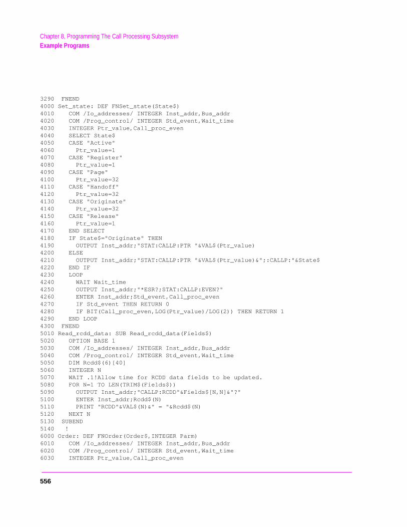
Chapter 8, Programming The Call Processing SubsystemExample Programs
3290 FNEND4000 Set_state: DEF FNSet_state(State$)4010 COM /Io_addresses/ INTEGER Inst_addr,Bus_addr4020 COM /Prog_control/ INTEGER Std_event,Wait_time4030 INTEGER Ptr_value,Call_proc_even4040 SELECT State$4050 CASE "Active"4060 Ptr_value=14070 CASE "Register"4080 Ptr_value=14090 CASE "Page"4100 Ptr_value=324110 CASE "Handoff"4120 Ptr_value=324130 CASE "Originate"4140 Ptr_value=324150 CASE "Release"4160 Ptr_value=14170 END SELECT4180 IF State$="Originate" THEN4190 OUTPUT Inst_addr;"STAT:CALLP:PTR "&VAL$(Ptr_value)4200 ELSE4210 OUTPUT Inst_addr;"STAT:CALLP:PTR "&VAL$(Ptr_value)&";:CALLP:"&State$4220 END IF4230 LOOP4240 WAIT Wait_time4250 OUTPUT Inst_addr;"*ESR?;STAT:CALLP:EVEN?"4260 ENTER Inst_addr;Std_event,Call_proc_even4270 IF Std_event THEN RETURN 04280 IF BIT(Call_proc_even,LOG(Ptr_value)/LOG(2)) THEN RETURN 14290 END LOOP4300 FNEND5010 Read_rcdd_data: SUB Read_rcdd_data(Fields$)5020 OPTION BASE 15030 COM /Io_addresses/ INTEGER Inst_addr,Bus_addr5040 COM /Prog_control/ INTEGER Std_event,Wait_time5050 DIM Rcdd$(6)[40]5060 INTEGER N5070 WAIT .1!Allow time for RCDD data fields to be updated.5080 FOR N=1 TO LEN(TRIM$(Fields$))5090 OUTPUT Inst_addr;"CALLP:RCDD"&Fields$[N,N]&"?"5100 ENTER Inst_addr;Rcdd$(N)5110 PRINT "RCDD"&VAL$(N)&" = "&Rcdd$(N)5120 NEXT N5130 SUBEND5140 !6000 Order: DEF FNOrder(Order$,INTEGER Parm)6010 COM /Io_addresses/ INTEGER Inst_addr,Bus_addr6020 COM /Prog_control/ INTEGER Std_event,Wait_time6030 INTEGER Ptr_value,Call_proc_even
556
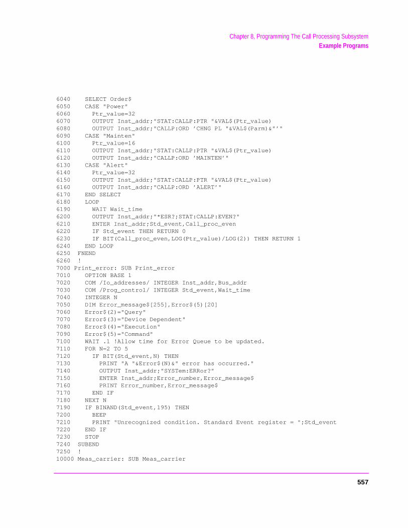
Chapter 8, Programming The Call Processing SubsystemExample Programs
6040 SELECT Order$6050 CASE "Power"6060 Ptr_value=326070 OUTPUT Inst_addr;"STAT:CALLP:PTR "&VAL$(Ptr_value)6080 OUTPUT Inst_addr;"CALLP:ORD ’CHNG PL "&VAL$(Parm)&"’"6090 CASE "Mainten"6100 Ptr_value=166110 OUTPUT Inst_addr;"STAT:CALLP:PTR "&VAL$(Ptr_value)6120 OUTPUT Inst_addr;"CALLP:ORD ’MAINTEN’"6130 CASE "Alert"6140 Ptr_value=326150 OUTPUT Inst_addr;"STAT:CALLP:PTR "&VAL$(Ptr_value)6160 OUTPUT Inst_addr;"CALLP:ORD ’ALERT’"6170 END SELECT6180 LOOP6190 WAIT Wait_time6200 OUTPUT Inst_addr;"*ESR?;STAT:CALLP:EVEN?"6210 ENTER Inst_addr;Std_event,Call_proc_even6220 IF Std_event THEN RETURN 06230 IF BIT(Call_proc_even,LOG(Ptr_value)/LOG(2)) THEN RETURN 16240 END LOOP6250 FNEND6260 !7000 Print_error: SUB Print_error7010 OPTION BASE 17020 COM /Io_addresses/ INTEGER Inst_addr,Bus_addr7030 COM /Prog_control/ INTEGER Std_event,Wait_time7040 INTEGER N7050 DIM Error_message$[255],Error$(5)[20]7060 Error$(2)="Query"7070 Error$(3)="Device Dependent"7080 Error$(4)="Execution"7090 Error$(5)="Command"7100 WAIT .1 !Allow time for Error Queue to be updated.7110 FOR N=2 TO 57120 IF BIT(Std_event,N) THEN7130 PRINT "A "&Error$(N)&" error has occurred."7140 OUTPUT Inst_addr;"SYSTem:ERRor?"7150 ENTER Inst_addr;Error_number,Error_message$7160 PRINT Error_number,Error_message$7170 END IF7180 NEXT N7190 IF BINAND(Std_event,195) THEN7200 BEEP7210 PRINT "Unrecognized condition. Standard Event register = ";Std_event7220 END IF7230 STOP7240 SUBEND7250 !10000 Meas_carrier: SUB Meas_carrier
557
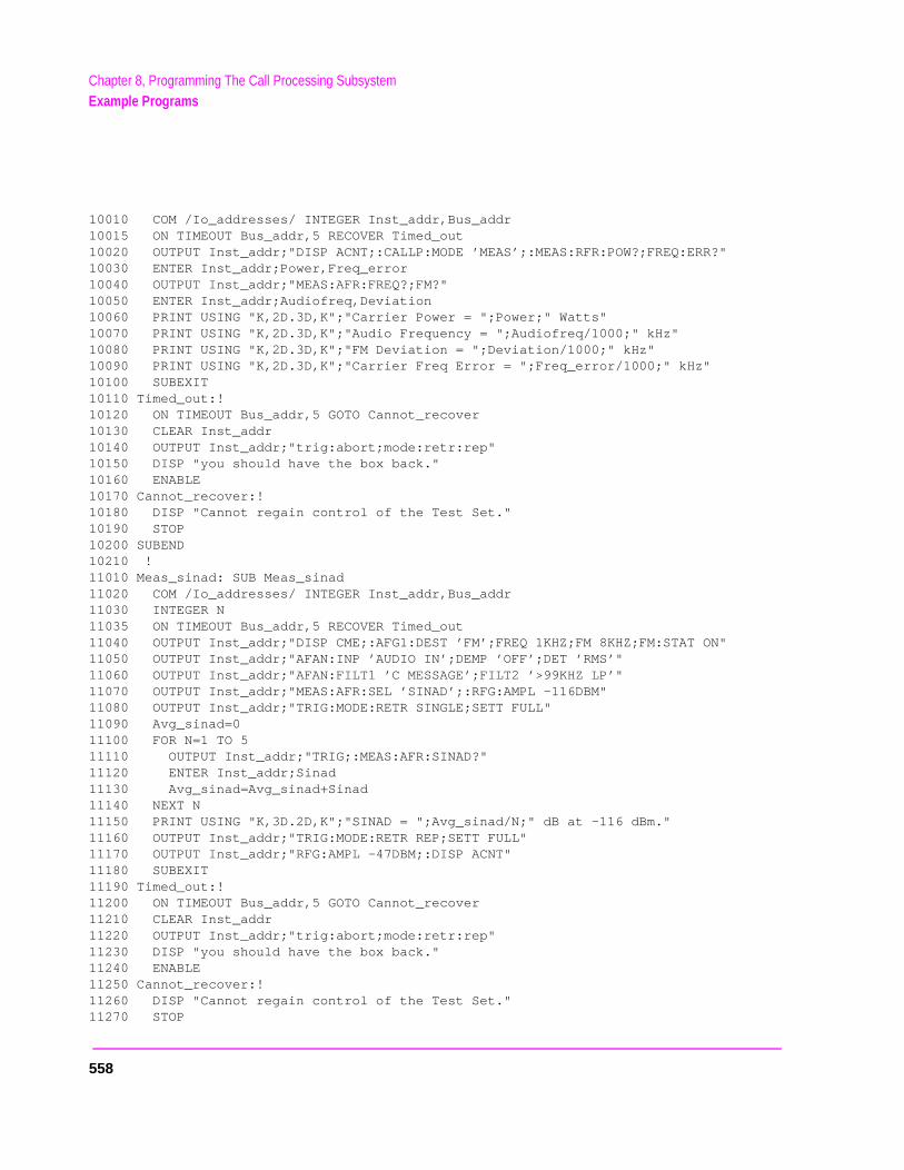
Chapter 8, Programming The Call Processing SubsystemExample Programs
10010 COM /Io_addresses/ INTEGER Inst_addr,Bus_addr10015 ON TIMEOUT Bus_addr,5 RECOVER Timed_out10020 OUTPUT Inst_addr;"DISP ACNT;:CALLP:MODE ’MEAS’;:MEAS:RFR:POW?;FREQ:ERR?"10030 ENTER Inst_addr;Power,Freq_error10040 OUTPUT Inst_addr;"MEAS:AFR:FREQ?;FM?"10050 ENTER Inst_addr;Audiofreq,Deviation10060 PRINT USING "K,2D.3D,K";"Carrier Power = ";Power;" Watts"10070 PRINT USING "K,2D.3D,K";"Audio Frequency = ";Audiofreq/1000;" kHz"10080 PRINT USING "K,2D.3D,K";"FM Deviation = ";Deviation/1000;" kHz"10090 PRINT USING "K,2D.3D,K";"Carrier Freq Error = ";Freq_error/1000;" kHz"10100 SUBEXIT10110 Timed_out:!10120 ON TIMEOUT Bus_addr,5 GOTO Cannot_recover10130 CLEAR Inst_addr10140 OUTPUT Inst_addr;"trig:abort;mode:retr:rep"10150 DISP "you should have the box back."10160 ENABLE10170 Cannot_recover:!10180 DISP "Cannot regain control of the Test Set."10190 STOP10200 SUBEND10210 !11010 Meas_sinad: SUB Meas_sinad11020 COM /Io_addresses/ INTEGER Inst_addr,Bus_addr11030 INTEGER N11035 ON TIMEOUT Bus_addr,5 RECOVER Timed_out11040 OUTPUT Inst_addr;"DISP CME;:AFG1:DEST ’FM’;FREQ 1KHZ;FM 8KHZ;FM:STAT ON"11050 OUTPUT Inst_addr;"AFAN:INP ’AUDIO IN’;DEMP ’OFF’;DET ’RMS’"11060 OUTPUT Inst_addr;"AFAN:FILT1 ’C MESSAGE’;FILT2 ’>99KHZ LP’"11070 OUTPUT Inst_addr;"MEAS:AFR:SEL ’SINAD’;:RFG:AMPL -116DBM"11080 OUTPUT Inst_addr;"TRIG:MODE:RETR SINGLE;SETT FULL"11090 Avg_sinad=011100 FOR N=1 TO 511110 OUTPUT Inst_addr;"TRIG;:MEAS:AFR:SINAD?"11120 ENTER Inst_addr;Sinad11130 Avg_sinad=Avg_sinad+Sinad11140 NEXT N11150 PRINT USING "K,3D.2D,K";"SINAD = ";Avg_sinad/N;" dB at -116 dBm."11160 OUTPUT Inst_addr;"TRIG:MODE:RETR REP;SETT FULL"11170 OUTPUT Inst_addr;"RFG:AMPL -47DBM;:DISP ACNT"11180 SUBEXIT11190 Timed_out:! 11200 ON TIMEOUT Bus_addr,5 GOTO Cannot_recover11210 CLEAR Inst_addr11220 OUTPUT Inst_addr;"trig:abort;mode:retr:rep"11230 DISP "you should have the box back."11240 ENABLE11250 Cannot_recover:!11260 DISP "Cannot regain control of the Test Set."11270 STOP
558

Chapter 8, Programming The Call Processing SubsystemExample Programs
11280 SUBEND11290 !
559
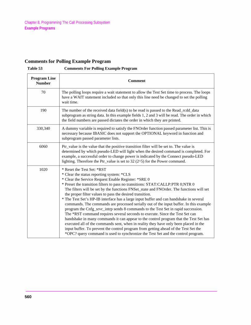
Chapter 8, Programming The Call Processing SubsystemExample Programs
ple
as
Comments for Polling Example ProgramTable 53 Comments For Polling Example Program
Program Line Number
Comment
70 The polling loops require a wait statement to allow the Test Set time to process. The loops have a WAIT statement included so that only this line need be changed to set the polling wait time.
190 The number of the received data field(s) to be read is passed to the Read_rcdd_data subprogram as string data. In this example fields 1, 2 and 3 will be read. The order in which the field numbers are passed dictates the order in which they are printed.
330,340 A dummy variable is required to satisfy the FNOrder function passed parameter list. This is necessary because IBASIC does not support the OPTIONAL keyword in function and subprogram passed parameter lists.
6060 Ptr_value is the value that the positive transition filter will be set to. The value isdetermined by which pseudo-LED will light when the desired command is completed. For example, a successful order to change power is indicated by the Connect pseudo-LED lighting. Therefore the Ptr_value is set to 32 (2^5) for the Power command.
1020 * Reset the Test Set: *RST* Clear the status reporting system: *CLS* Clear the Service Request Enable Register: *SRE 0* Preset the transition filters to pass no transitions: STAT:CALLP:PTR 0;NTR 0
The filters will be set by the functions FNSet_state and FNOrder. The functions will setthe proper filter values to pass the desired transition.
* The Test Set’s HP-IB interface has a large input buffer and can handshake in severalcommands. The commands are processed serially out of the input buffer. In this examprogram the Cnfg_srvc_intrp sends 8 commands to the Test Set in rapid succession.The *RST command requires several seconds to execute. Since the Test Set canhandshake in many commands it can appear to the control program that the Test Set hexecuted all of the commands sent, when in reality they have only been placed in theinput buffer. To prevent the control program from getting ahead of the Test Set the*OPC? query command is used to synchronize the Test Set and the control program.
560
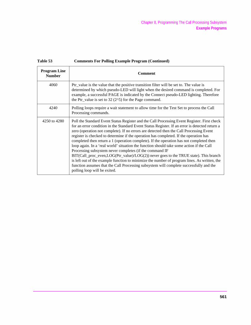
Chapter 8, Programming The Call Processing SubsystemExample Programs
h e
4060 Ptr_value is the value that the positive transition filter will be set to. The value isdetermined by which pseudo-LED will light when the desired command is completed. For example, a successful PAGE is indicated by the Connect pseudo-LED lighting. Therefore the Ptr_value is set to 32 (2^5) for the Page command.
4240 Polling loops require a wait statement to allow time for the Test Set to process the Call Processing commands.
4250 to 4280 Poll the Standard Event Status Register and the Call Processing Event Register. First check for an error condition in the Standard Event Status Register. If an error is detected return a zero (operation not complete). If no errors are detected then the Call Processing Event register is checked to determine if the operation has completed. If the operation has completed then return a 1 (operation complete). If the operation has not completed then loop again. In a ‘real world’ situation the function should take some action if the Call Processing subsystem never completes (if the command IF BIT(Call_proc_even,LOG(Ptr_value)/LOG(2)) never goes to the TRUE state). This brancis left out of the example function to minimize the number of program lines. As written, thfunction assumes that the Call Processing subsystem will complete successfully and thepolling loop will be exited.
Table 53 Comments For Polling Example Program (Continued)
Program Line Number
Comment
561

Chapter 8, Programming The Call Processing SubsystemExample Programs
562

9
Error Messages
563
you t.
General Information About Error Messages
Information concerning error messages displayed by the Test Set may be found in one of the following manuals:
• User’s Guides • Programmer’s Guide • Assembly Level Repair Manual • HP Instrument BASIC User’s Handbook:
• HP Instrument BASIC Users Handbook (HP P/N E2083-90601)
The format of the displayed message determines which manual contains informationabout the error message. There are four basic error message formats:
• Positive numbered error messages • IBASIC error messages • HP-IB error messages • Text only error messages
The following paragraphs give a brief description of each message format and directto the manual to look in for information about error messages displayed in that forma
564
Positive Numbered Error Messages
Positive numbered error messages are generally associated with IBASIC. Refer to the HP Instrument BASIC User’s Handbook for information on IBASIC error messages.
Positive numbered error messages take the form: ERROR XX <error message>
For example
Error 54 Duplicate file name
or
Error 80 in 632 Medium changed or not in drive
565
Negative Numbered Error Messages
Negative numbers preceding the error messages text correspond to the error conditions outlined in the Standard Commands for Programmable Instruments (SCPI). For more information on SCPI, order the following book,
A Beginner’s Guide to SCPI Addison-Wesley Publishing Company ISBN 0-201-56350-9 HP P/N 5010-7166
or contact,
Fred Bode, Executive Director SCPI Consortium 8380 Hercules Drive, Suite P3La Mesa, CA 91942 Phone: (619) 697-8790, FAX: (619) 697-5955 CompuServe Number: 76516,254
Negative numbered error messages take the form: ERROR -XX <error message>
For example
Error -128 Numeric data not allowed
or
Error -141 Invalid character data
566
IBASIC Error Messages
IBASIC Error Messages are associated with IBASIC operation. IBASIC error messages can have both positive and negative numbers. Refer to the HP Instrument BASIC User’s Handbook for information on positive numbered error messages. Refer to the HP-IB Error Messages section for information on negative numbered error messages (the error message associated with a negative number is the same for HP-IB errors and IBASIC errors).
IBASIC error messages take the following form: IBASIC Error: -XX <error message>
For example
IBASIC Error: -286 Program runtime error
567
HP-IB Error Messages
HP-IB Error Messages are associated with HP-IB operation.
HP-IB error messages take the following form: HP-IB Error: -XX <error message> or HP-IB Error <error message>
For example
HP-IB Error: -410 Query INTERRUPTED.
or
HP-IB Error: Input value out of range.
568
e
Text Only Error Messages
Text only error messages are generally associated with manual operation of the Test Set. Refer to the HP 8920 or HP 8921 User’s Guide for information on text only error messages.
Text only error messages can also be displayed while running the Test Set’s built-indiagnostic or calibration utility programs. Refer to the HP 8920, HP 8921 Assembly Level Repair manual for information on text only error messages displayed while running thTest Set’s built-in diagnostic or calibration utility programs.
Text only error messages take the following form: This is an error message.
For example
Input value out of range.
569

y. eneral e ists, only knob ed on
(turn nd
The Message Display
During instrument operation, various messages may appear on the Test Set’s displaPrompt-type messages generally appear on the first line of the Test Set’s display. Goperating and error messages usually appear on the second line of the display. Sommessages are persistent; they remain displayed until the error condition no longer exor until another persistent message with greater priority occurs. Other messages aredisplayed when the error first occurs; they are removed when a key is pressed or theis turned, or when an HP-IB command is received. Many of the messages are displaythe MESSAGE screen until the instrument is turned off.
Messages that are about error conditions may tell you what to do to correct the errorsomething off, reduce a field’s value, press a certain key, and so forth). Messages aprompts are sometimes accompanied by a beep or warble.
NOTE: Warbles and Beeps
A warble sound indicates that an instrument-damaging event is occurring. Beepsoften occur only with the first occurrence of the message. Prompts are generallysilent.
570
e h) has
e d, it hat
Non-Recoverable Firmware Error
The non-recoverable firmware error is very important. It appears when an unanticipated event occurs that the Test Set’s firmware cannot handle. The message appears in thcenter of the Test Set’s display and (except for the two lines in the second paragrapthe following form:
Non-recoverable firmware error. Please record the 2 lines oftext below and contact Hewlett Packard through your localservice center or by calling (800) 827-3848 (USA, collect) andasking to speak to the 8920A Service Engineer.
'Address error exception'at line number 0
To continue operation, turn POWER off and back on.
Follow the instructions in the message.
Unfortunately, you will not be able to recover from this condition. You must switch thTest Set off and back on. When you rerun the test where the Error Message occurremay not occur again. If it does reappear, it would be helpful to HP to record exactly wthe configuration of the instrument was when the error appeared and contact HP.
571

HP-IB Errors
Most HP-IB errors occur when the control program attempts to query a measurement that is not currently available, or tries to access an instrument connected to the external HP-IB without configuring the Test Set as the System Controller. When diagnosing the cause of an error condition check for these conditions first.
572
. n to
n
rnal
t is not
Text Only HP-IB Errors
Un-numbered (text only) HP-IB error messages are generally self-explanatory. For example, trying to retrieve a saved register that does not exist generates the following error message:
HP-IB Error: Register does not exist.
The following list contains a subset of the Test Set’s text only HP-IB error messagesThese messages represent error conditions which may require explanation in additiothe error message text.
HP-IB Error during Procedure catalog. Check Config.
This error occurs when the Test Set fails to access an external HP-IB disk drive whetrying to obtain a catalog of procedure files. This would occur when the Select Procedure Location: field on the TESTS (Main Menu) screen is set to Disk and the operator then tries to select a procedure filename using the Select Procedure FIlename: field. Ensure that the Mode field on the I/O CONFIGURE screen is set to Control and that the External Disk Specification field on the TESTS (External Devices) screen has the correct mass storage volume specifier for the extedisk drive.
HP-IB Query Error. Check instrument state.
This message usually appears when the control program queries a measurement thacurrently available (on the currently displayed screen and in the ON state), such as querying the TX Frequency measurement when TX Freq Error is displayed. This message may also be immediately followed by the message, HP-IB Error: −420: Query UNTERMINATED.
573

tile
and
ction ata er to
HP-IB Error: Not Enough Memory Available for Save.
This message will be generated when the control program tries to save the current Test Set state into a Save/Recall register using the REG:SAVE commands, but there is insufficient memory available in the Test Set. The Test Set’s non-volatile RAM is shared by the following resources:
• IBASIC programs • Save/Recall registers • RAM Disk
In order to save the current Test Set state into a Save/Recall register more non-volaRAM will have to be made available. This can be done by,
• reducing the size of the IBASIC program • deleting one or more existing Save/Recall registers • recovering RAM Disk space
The ROM Disk utility RAM_USAGE will display the total amount of non-volatile RAMinstalled in the Test Set, the RAM Disk allocation, the Save/Recall register allocationthe amount of non-volatile RAM available to IBASIC.
HP-IB Error: HP-IB Units cause invalid conversion of attr.
This error is generated when trying to change Attribute Units and one of the Data Funvalues is set to zero. If this error is encountered the programmer must change the DFunction settings to values that can be converted to the new units_of_measure. Ref<blue>"Changing Attribute Units." on page 85 for more details.
574
bus,
ternal
s. It
Numbered HP-IB Error Descriptions
The following HP-IB errors can be generated under any of the following conditions:
• controlling the Test Set with an IBASIC program running on the built-in IBASIC controller
• controlling HP-IB devices/instruments, connected to the Test Set’s external HP-IBwith an IBASIC program running on the built-in IBASIC controller
• controlling the Test Set with a program running on an external controller
• using the Test Set manually to print to an external HP-IB printer
• using the Test Set manually to access procedure/library/code files stored on an exHP-IB disk
NOTE: HP-IB Parser. The term “Parser” is used in the following error message descriptionrefers to the Test Set’s HP-IB command parser.
575
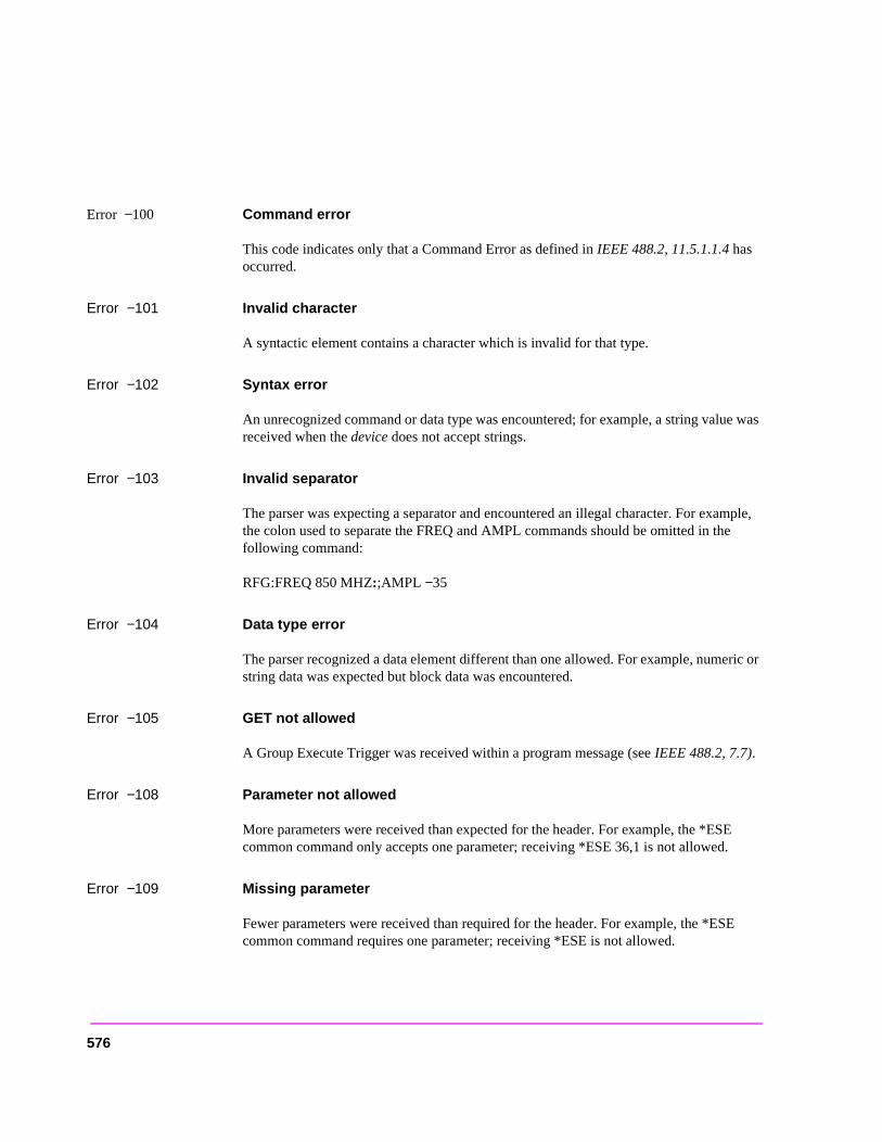
Error −100 Command error
This code indicates only that a Command Error as defined in IEEE 488.2, 11.5.1.1.4 has occurred.
Error −101 Invalid character
A syntactic element contains a character which is invalid for that type.
Error −102 Syntax error
An unrecognized command or data type was encountered; for example, a string value was received when the device does not accept strings.
Error −103 Invalid separator
The parser was expecting a separator and encountered an illegal character. For example, the colon used to separate the FREQ and AMPL commands should be omitted in the following command:
RFG:FREQ 850 MHZ:;AMPL −35
Error −104 Data type error
The parser recognized a data element different than one allowed. For example, numeric or string data was expected but block data was encountered.
Error −105 GET not allowed
A Group Execute Trigger was received within a program message (see IEEE 488.2, 7.7).
Error −108 Parameter not allowed
More parameters were received than expected for the header. For example, the *ESE common command only accepts one parameter; receiving *ESE 36,1 is not allowed.
Error −109 Missing parameter
Fewer parameters were received than required for the header. For example, the *ESE common command requires one parameter; receiving *ESE is not allowed.
576
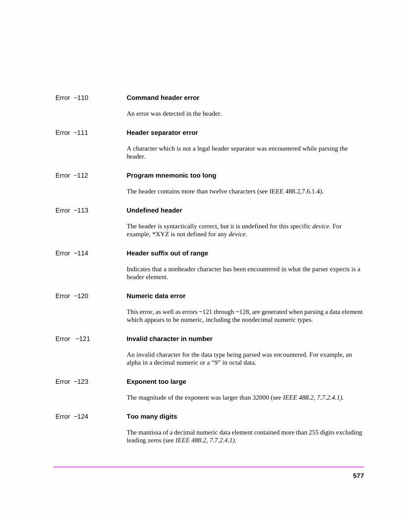
uding
Error −110 Command header error
An error was detected in the header.
Error −111 Header separator error
A character which is not a legal header separator was encountered while parsing the header.
Error −112 Program mnemonic too long
The header contains more than twelve characters (see IEEE 488.2,7.6.1.4).
Error −113 Undefined header
The header is syntactically correct, but it is undefined for this specific device. For example, *XYZ is not defined for any device.
Error −114 Header suffix out of range
Indicates that a nonheader character has been encountered in what the parser expects is a header element.
Error −120 Numeric data error
This error, as well as errors −121 through −128, are generated when parsing a data element which appears to be numeric, including the nondecimal numeric types.
Error −121 Invalid character in number
An invalid character for the data type being parsed was encountered. For example, an alpha in a decimal numeric or a “9” in octal data.
Error −123 Exponent too large
The magnitude of the exponent was larger than 32000 (see IEEE 488.2, 7.7.2.4.1).
Error −124 Too many digits
The mantissa of a decimal numeric data element contained more than 255 digits exclleading zeros (see IEEE 488.2, 7.7.2.4.1).
577
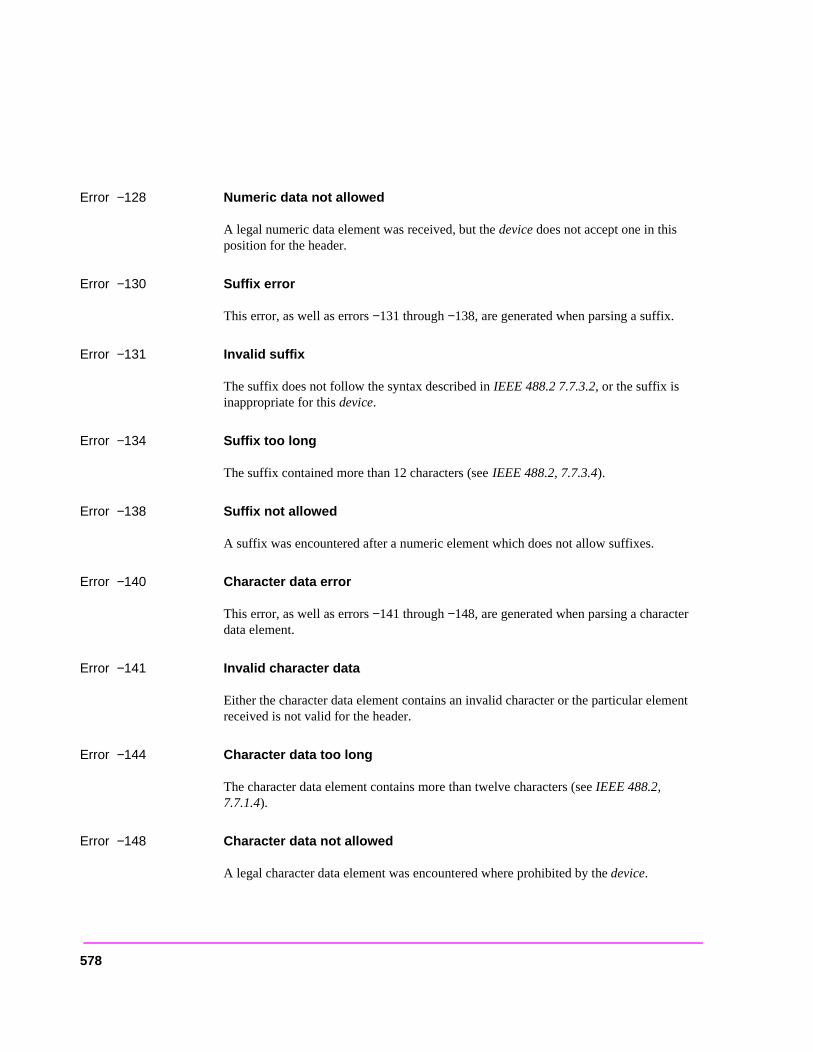
Error −128 Numeric data not allowed
A legal numeric data element was received, but the device does not accept one in this position for the header.
Error −130 Suffix error
This error, as well as errors −131 through −138, are generated when parsing a suffix.
Error −131 Invalid suffix
The suffix does not follow the syntax described in IEEE 488.2 7.7.3.2, or the suffix is inappropriate for this device.
Error −134 Suffix too long
The suffix contained more than 12 characters (see IEEE 488.2, 7.7.3.4).
Error −138 Suffix not allowed
A suffix was encountered after a numeric element which does not allow suffixes.
Error −140 Character data error
This error, as well as errors −141 through −148, are generated when parsing a character data element.
Error −141 Invalid character data
Either the character data element contains an invalid character or the particular element received is not valid for the header.
Error −144 Character data too long
The character data element contains more than twelve characters (see IEEE 488.2, 7.7.1.4).
Error −148 Character data not allowed
A legal character data element was encountered where prohibited by the device.
578
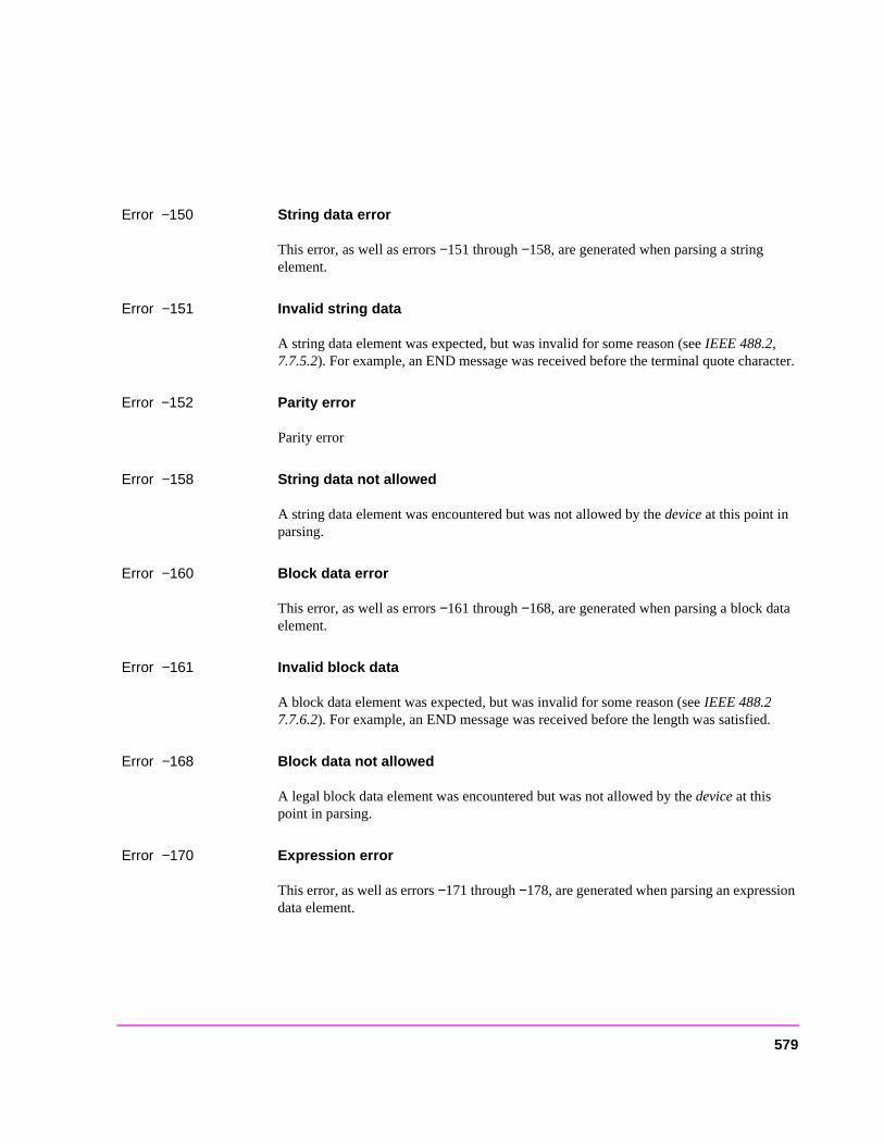
Error −150 String data error
This error, as well as errors −151 through −158, are generated when parsing a string element.
Error −151 Invalid string data
A string data element was expected, but was invalid for some reason (see IEEE 488.2, 7.7.5.2). For example, an END message was received before the terminal quote character.
Error −152 Parity error
Parity error
Error −158 String data not allowed
A string data element was encountered but was not allowed by the device at this point in parsing.
Error −160 Block data error
This error, as well as errors −161 through −168, are generated when parsing a block data element.
Error −161 Invalid block data
A block data element was expected, but was invalid for some reason (see IEEE 488.2 7.7.6.2). For example, an END message was received before the length was satisfied.
Error −168 Block data not allowed
A legal block data element was encountered but was not allowed by the device at this point in parsing.
Error −170 Expression error
This error, as well as errors −171 through −178, are generated when parsing an expression data element.
579
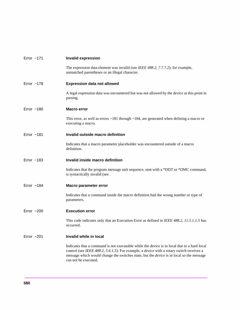
Error −171 Invalid expression
The expression data element was invalid (see IEEE 488.2, 7.7.7.2); for example, unmatched parentheses or an illegal character.
Error −178 Expression data not allowed
A legal expression data was encountered but was not allowed by the device at this point in parsing.
Error −180 Macro error
This error, as well as errors −181 through −184, are generated when defining a macro or executing a macro.
Error −181 Invalid outside macro definition
Indicates that a macro parameter placeholder was encountered outside of a macro definition.
Error −183 Invalid inside macro definition
Indicates that the program message unit sequence, sent with a *DDT or *DMC command, is syntactically invalid (see .
Error −184 Macro parameter error
Indicates that a command inside the macro definition had the wrong number or type of parameters.
Error −200 Execution error
This code indicates only that an Execution Error as defined in IEEE 488.2, 11.5.1.1.5 has occurred.
Error −201 Invalid while in local
Indicates that a command is not executable while the device is in local due to a hard local control (see IEEE 488.2, 5.6.1.5). For example, a device with a rotary switch receives a message which would change the switches state, but the device is in local so the message can not be executed.
580
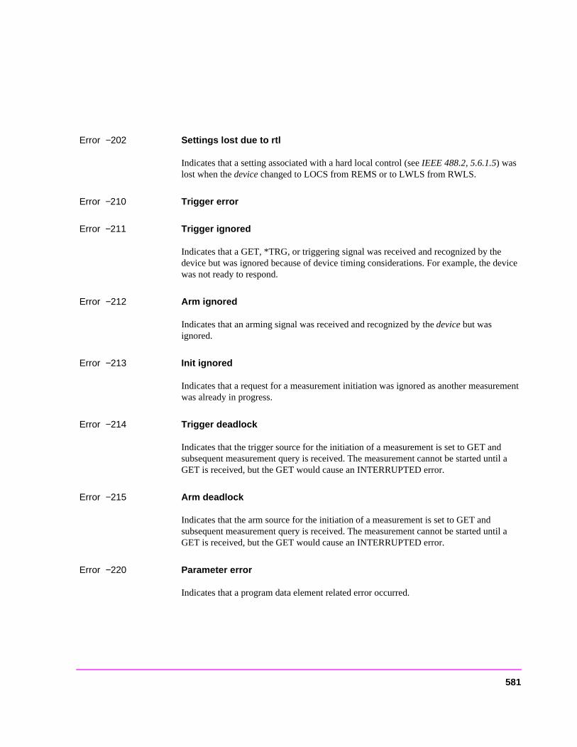
Error −202 Settings lost due to rtl
Indicates that a setting associated with a hard local control (see IEEE 488.2, 5.6.1.5) was lost when the device changed to LOCS from REMS or to LWLS from RWLS.
Error −210 Trigger error
Error −211 Trigger ignored
Indicates that a GET, *TRG, or triggering signal was received and recognized by the device but was ignored because of device timing considerations. For example, the device was not ready to respond.
Error −212 Arm ignored
Indicates that an arming signal was received and recognized by the device but was ignored.
Error −213 Init ignored
Indicates that a request for a measurement initiation was ignored as another measurement was already in progress.
Error −214 Trigger deadlock
Indicates that the trigger source for the initiation of a measurement is set to GET and subsequent measurement query is received. The measurement cannot be started until a GET is received, but the GET would cause an INTERRUPTED error.
Error −215 Arm deadlock
Indicates that the arm source for the initiation of a measurement is set to GET and subsequent measurement query is received. The measurement cannot be started until a GET is received, but the GET would cause an INTERRUPTED error.
Error −220 Parameter error
Indicates that a program data element related error occurred.
581
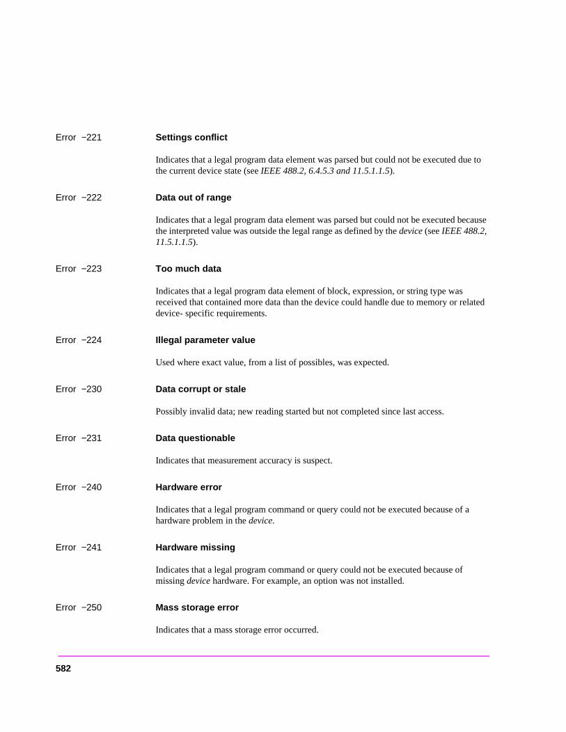
Error −221 Settings conflict
Indicates that a legal program data element was parsed but could not be executed due to the current device state (see IEEE 488.2, 6.4.5.3 and 11.5.1.1.5).
Error −222 Data out of range
Indicates that a legal program data element was parsed but could not be executed because the interpreted value was outside the legal range as defined by the device (see IEEE 488.2, 11.5.1.1.5).
Error −223 Too much data
Indicates that a legal program data element of block, expression, or string type was received that contained more data than the device could handle due to memory or related device- specific requirements.
Error −224 Illegal parameter value
Used where exact value, from a list of possibles, was expected.
Error −230 Data corrupt or stale
Possibly invalid data; new reading started but not completed since last access.
Error −231 Data questionable
Indicates that measurement accuracy is suspect.
Error −240 Hardware error
Indicates that a legal program command or query could not be executed because of a hardware problem in the device.
Error −241 Hardware missing
Indicates that a legal program command or query could not be executed because of missing device hardware. For example, an option was not installed.
Error −250 Mass storage error
Indicates that a mass storage error occurred.
582
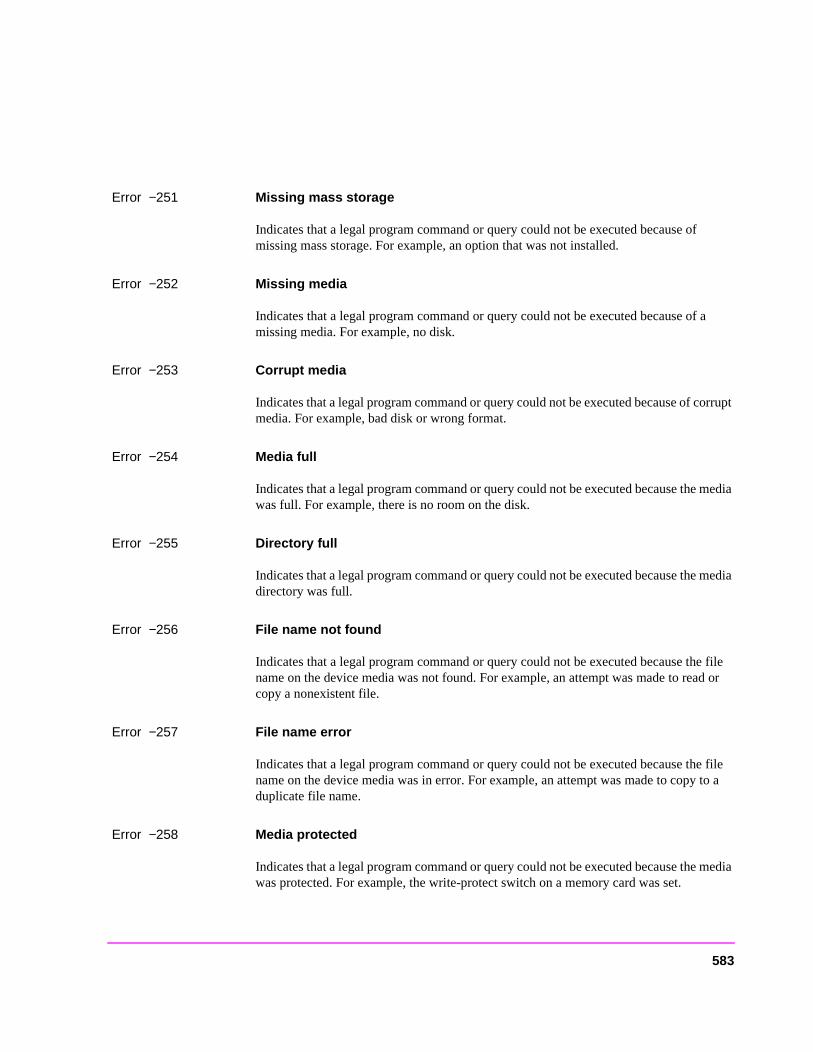
Error −251 Missing mass storage
Indicates that a legal program command or query could not be executed because of missing mass storage. For example, an option that was not installed.
Error −252 Missing media
Indicates that a legal program command or query could not be executed because of a missing media. For example, no disk.
Error −253 Corrupt media
Indicates that a legal program command or query could not be executed because of corrupt media. For example, bad disk or wrong format.
Error −254 Media full
Indicates that a legal program command or query could not be executed because the media was full. For example, there is no room on the disk.
Error −255 Directory full
Indicates that a legal program command or query could not be executed because the media directory was full.
Error −256 File name not found
Indicates that a legal program command or query could not be executed because the file name on the device media was not found. For example, an attempt was made to read or copy a nonexistent file.
Error −257 File name error
Indicates that a legal program command or query could not be executed because the file name on the device media was in error. For example, an attempt was made to copy to a duplicate file name.
Error −258 Media protected
Indicates that a legal program command or query could not be executed because the media was protected. For example, the write-protect switch on a memory card was set.
583
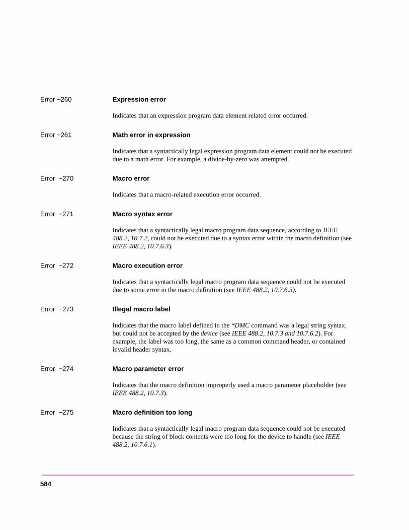
Error −260 Expression error
Indicates that an expression program data element related error occurred.
Error −261 Math error in expression
Indicates that a syntactically legal expression program data element could not be executed due to a math error. For example, a divide-by-zero was attempted.
Error −270 Macro error
Indicates that a macro-related execution error occurred.
Error −271 Macro syntax error
Indicates that a syntactically legal macro program data sequence, according to IEEE 488.2, 10.7.2, could not be executed due to a syntax error within the macro definition (see IEEE 488.2, 10.7.6.3).
Error −272 Macro execution error
Indicates that a syntactically legal macro program data sequence could not be executed due to some error in the macro definition (see IEEE 488.2, 10.7.6.3).
Error −273 Illegal macro label
Indicates that the macro label defined in the *DMC command was a legal string syntax, but could not be accepted by the device (see IEEE 488.2, 10.7.3 and 10.7.6.2). For example, the label was too long, the same as a common command header, or contained invalid header syntax.
Error −274 Macro parameter error
Indicates that the macro definition improperly used a macro parameter placeholder (see IEEE 488.2, 10.7.3).
Error −275 Macro definition too long
Indicates that a syntactically legal macro program data sequence could not be executed because the string of block contents were too long for the device to handle (see IEEE 488.2, 10.7.6.1).
584
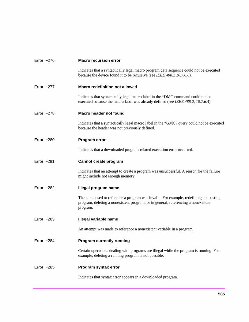
Error −276 Macro recursion error
Indicates that a syntactically legal macro program data sequence could not be executed because the device found it to be recursive (see IEEE 488.2 10.7.6.6).
Error −277 Macro redefinition not allowed
Indicates that syntactically legal macro label in the *DMC command could not be executed because the macro label was already defined (see IEEE 488.2, 10.7.6.4).
Error −278 Macro header not found
Indicates that a syntactically legal macro label in the *GMC? query could not be executed because the header was not previously defined.
Error −280 Program error
Indicates that a downloaded program-related execution error occurred.
Error −281 Cannot create program
Indicates that an attempt to create a program was unsuccessful. A reason for the failure might include not enough memory.
Error −282 Illegal program name
The name used to reference a program was invalid. For example, redefining an existing program, deleting a nonexistent program, or in general, referencing a nonexistent program.
Error −283 Illegal variable name
An attempt was made to reference a nonexistent variable in a program.
Error −284 Program currently running
Certain operations dealing with programs are illegal while the program is running. For example, deleting a running program is not possible.
Error −285 Program syntax error
Indicates that syntax error appears in a downloaded program.
585
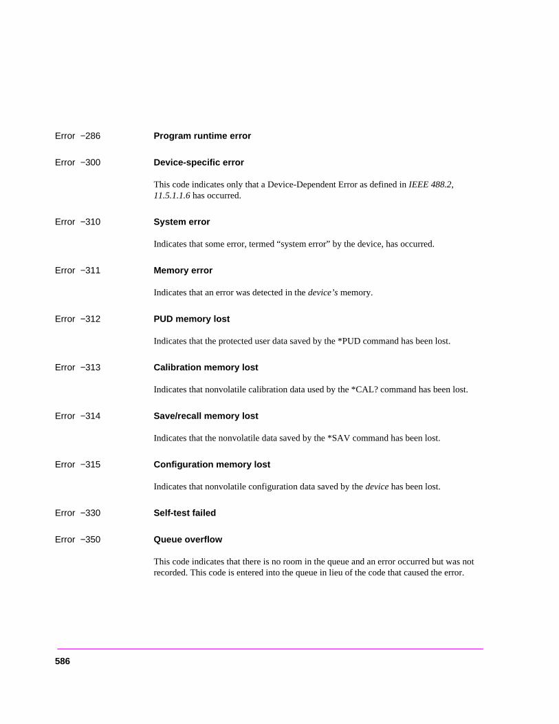
Error −286 Program runtime error
Error −300 Device-specific error
This code indicates only that a Device-Dependent Error as defined in IEEE 488.2, 11.5.1.1.6 has occurred.
Error −310 System error
Indicates that some error, termed “system error” by the device, has occurred.
Error −311 Memory error
Indicates that an error was detected in the device’s memory.
Error −312 PUD memory lost
Indicates that the protected user data saved by the *PUD command has been lost.
Error −313 Calibration memory lost
Indicates that nonvolatile calibration data used by the *CAL? command has been lost.
Error −314 Save/recall memory lost
Indicates that the nonvolatile data saved by the *SAV command has been lost.
Error −315 Configuration memory lost
Indicates that nonvolatile configuration data saved by the device has been lost.
Error −330 Self-test failed
Error −350 Queue overflow
This code indicates that there is no room in the queue and an error occurred but was not recorded. This code is entered into the queue in lieu of the code that caused the error.
586
Error −400 Query error
This code indicates only that a Query Error as defined in IEEE 488.2 11.5.1.1.7 and 6.3 has occurred.
Error −410 Query INTERRUPTED
Indicates that a condition causing an INTERRUPTED Query error occurred (see IEEE 488.2, 6.3.2.3). For example, a query followed by DAB or GET before a response was completely sent.
This message appears when you query a measurement without immediately entering the returned value into a variable. For example, the following program lines query the TX Frequency measurement and enter its value into a variable (Rf_freq):
OUTPUT 714;"MEAS:RFR:FREQ:ABS?"ENTER 714;Rf_freq
Error −420 Query UNTERMINATED
Indicates that a condition causing an UNTERMINATED Query error occurred (see IEEE 488.2, 6.3.2.2.). For example, the device was addressed to talk and an incomplete program message was received.
This message usually appears when trying to access a measurement that is not active. For example, you cannot query the DTMF Decoder measurements from the DUPLEX TEST screen, or query the TX Frequency measurement when the TX Freq Error measurement is displayed.
Error −430 Query DEADLOCKED
Indicates that a condition causing a DEADLOCKED Query error occurred (see IEEE 488.2, 6.3.1.7). For example, both input buffer and output buffer are full and the device cannot continue.
Error −440 Query UNTERMINATED after indefinite response
Indicates that a query was received in the same program message after a query requesting an indefinite response was executed (see IEEE 488.2, 6.5.7.5.7).
587
ut e Test
ount
ostic
ssage , or as not
el
hen the
ing
Error −606 Update of Input Module Relay Switch Count file failed.
Indicates that the Test Set was not able to update the Input Module Relay Switch Count EEPROM file with the current switch count data from the non-volatile RAM switch count array. This error is most probably generated as a result of a hardware error or failure. Refer to the Test Set’s Assembly Level Repair for diagnostic information.
Error −607 Checksum of Non-Volatile RAM Relay Count data bad.
Indicates that the Test Set was not able to generate the proper checksum for the InpModule Relay Switch Count data from the non-volatile RAM switch count array. Thiserror is most probably generated as a result of a hardware error or failure. Refer to thSet’s for diagnostic information.
Error −608 Initialization of Input Module Relay Count file failed.
Indicates that the Test Set was not able to initialize the Input Module Relay Switch CEEPROM file during installation of a new input module. This error is most probably generated as a result of a hardware error or failure. Refer to the Test Set’s for diagninformation.
Error −1300 Order attempted while not in Connect state.
Indicates that an attempt was made to send an order type Mobile Station Control Me(that is - order a change in power level, put the mobile station in maintenance modesend an alert message to the mobile station) when the Call Processing Subsystem win the Connect state.
Error −1301 Handoff attempted while not in Connect state.
Indicates that an attempt was made to handoff a mobile station to a new voice channwhen the Call Processing Subsystem was not in the Connect state.
Error −1302 Release attempted while not in Connect state.
Indicates that an attempt was made to send a Release message to a mobile station wCall Processing Subsystem was not in the Connect state.
Error −1303 Page attempted while not in Active state.
Indicates that an attempt was made to Page a mobile station when the Call ProcessSubsystem was not in the Active state.
588
et to
0
to 20
20
Error −1304 Origination attempted while not in Active state.
Indicates that a mobile station attempted to originate a call to the simulated Base Station when the Call Processing Subsystem was not in the Active state.
Error −1305 Registration attempted while not in Active state.
Indicates that an attempt was made to send a Registration message to a mobile station when the Call Processing Subsystem was not in the Active state.
Error −1306 Origination in progress.
Indicates that an attempt was made to; register, page, handoff, release, order a change in power level, put the mobile station in maintenance mode, or send an alert message to the mobile station while an origination was in progress.
Error −1307 Timeout occurred while attempting to register Mobile.
Indicates that the simulated Base Station’s internal timer expired before receiving a response from the mobile station during a registration attempt. The internal timer is s20 seconds when the Register state is entered.
Error −1308 Timeout occurred while attempting to page Mobile.
Indicates that the simulated Base Station’s internal timer expired before receiving a response from the mobile station during a page attempt. The internal timer is set to 2seconds when the Page state is entered.
Error −1309 Timeout occurred while attempting to access Mobile.
Indicates that the simulated Base Station’s internal timer expired before receiving a response from the mobile station during an access attempt. The internal timer is set seconds when the Access state is entered.
Error −1310 Timeout occurred while attempting to alert Mobile.
Indicates that the simulated Base Station’s internal timer expired before receiving a response from the mobile station during an alert attempt. The internal timer is set to seconds when the alert order is sent to the mobile station.
589
he t the is
esence whenssingeter canr Call
ation n the
n the
Error −1311 RF power loss indicates loss of Voice Channel.
When any Call Processing Subsystem screen is displayed (except the ANALOG MEAS screen) and the Call Processing Subsystem is in the Connect state, the host firmware constantly monitors the mobile station’s transmitted carrier power. If the power falls below 0.0005 Watts the simulated Base Station will terminate the call and return to tActive state. This error message is displayed if the host firmware has detected thamobile station’s carrier power has fallen below the 0.0005 Watts threshold. The call dropped and the Call Processing Subsystem returns to the Active state.
NOTE: In order to ensure that the host firmware makes the correct decisions regarding the prof the mobile stations’s RF carrier, the Test Set’s RF power meter should be zeroedfirst entering the Call Processing Subsystem (that is - the first time the Call ProceSubsystem is selected during a measurement session). Failure to zero the power mresult in erroneous RF power measurements. See “Conditioning The Test Set FoProcessing” in the HP 8920 User’s Guide for information on zeroing the RF Power metermanually or <blue>"Conditioning the Test Set for Call Processing" on page 452 of thismanual for information on zeroing the RF Power meter programmatically.
Error −1312 Data from RVC contains invalid bits in word [1,2,3].
Indicates that the decoded data received on the reverse voice channel contains invalid bits in word 1 and/or word 2 and/or word 3. The raw decoded data is displayed in hexadecimal format in the top right-hand portion of the CALL CONTROL screen. Raw decoded data is only displayed when the CALL CONTROL screen Display field is set to Data.
Error −1313 Timeout occurred while in Maintenance state.
Indicates that the simulated Base Station’s internal timer expired before the mobile stwas taken out of the maintenance state. The internal timer is set to 20 seconds whemaintenance order is sent to the mobile station.
Error −1314 Alert attempted while not in Maintenance or Connect state.
Indicates that an attempt was made to send an Alert order to the mobile station wheCall Processing Subsystem was not in the Maintenance state or Active state.
590
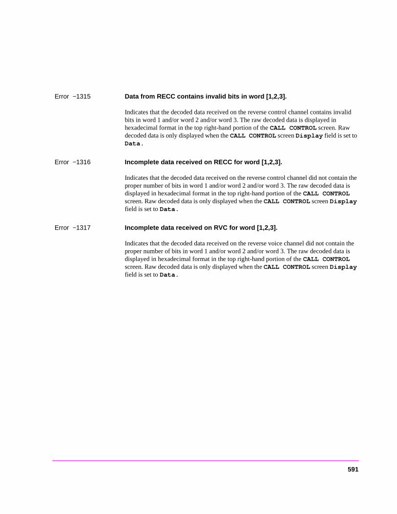
Error −1315 Data from RECC contains invalid bits in word [1,2,3].
Indicates that the decoded data received on the reverse control channel contains invalid bits in word 1 and/or word 2 and/or word 3. The raw decoded data is displayed in hexadecimal format in the top right-hand portion of the CALL CONTROL screen. Raw decoded data is only displayed when the CALL CONTROL screen Display field is set to Data.
Error −1316 Incomplete data received on RECC for word [1,2,3].
Indicates that the decoded data received on the reverse control channel did not contain the proper number of bits in word 1 and/or word 2 and/or word 3. The raw decoded data is displayed in hexadecimal format in the top right-hand portion of the CALL CONTROL screen. Raw decoded data is only displayed when the CALL CONTROL screen Display field is set to Data.
Error −1317 Incomplete data received on RVC for word [1,2,3].
Indicates that the decoded data received on the reverse voice channel did not contain the proper number of bits in word 1 and/or word 2 and/or word 3. The raw decoded data is displayed in hexadecimal format in the top right-hand portion of the CALL CONTROL screen. Raw decoded data is only displayed when the CALL CONTROL screen Display field is set to Data.
591

592
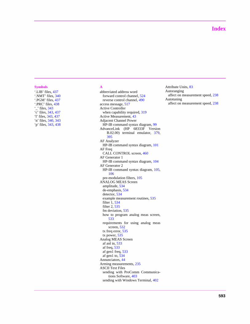
Index
Symbols‘.LIB’ files, 437‘.NMT’ files, 340‘.PGM’ files, 437‘.PRC’ files, 438‘_’ files, 343‘c’ files, 343, 437‘l’ files, 343, 437‘n’ files, 340, 343‘p’ files, 343, 438
Aabbreviated address word
forward control channel, 524reverse control channel, 490
access message, 517Active Controller
when capability required, 319Active Measurement, 43Adjacent Channel Power
HP-IB command syntax diagram, 99AdvanceLink (HP 68333F Version
B.02.00) terminal emulator, 379,395
AF AnalyzerHP-IB command syntax diagram, 101
AF FreqCALL CONTROL screen, 460
AF Generator 1HP-IB command syntax diagram, 104
AF Generator 2HP-IB command syntax diagram, 105,
106pre-modulation filters, 105
ANALOG MEAS Screenamplitude, 534de-emphasis, 534detector, 534example measurement routines, 535filter 1, 534filter 2, 535fm deviation, 535how to program analog meas screen,
533requirements for using analog meas
screen, 532tx freq error, 535tx power, 535
Analog MEAS Screenaf anl in, 533af freq, 533af gen1 freq, 533af gen1 to, 534
Annunciators, 44Arming measurements, 235ASCII Text Files
sending with ProComm Communica-tions Software, 403
sending with Windows Terminal, 402
Attribute Units, 83Autoranging
affect on measurement speed, 238Autotuning
affect on measurement speed, 238
593
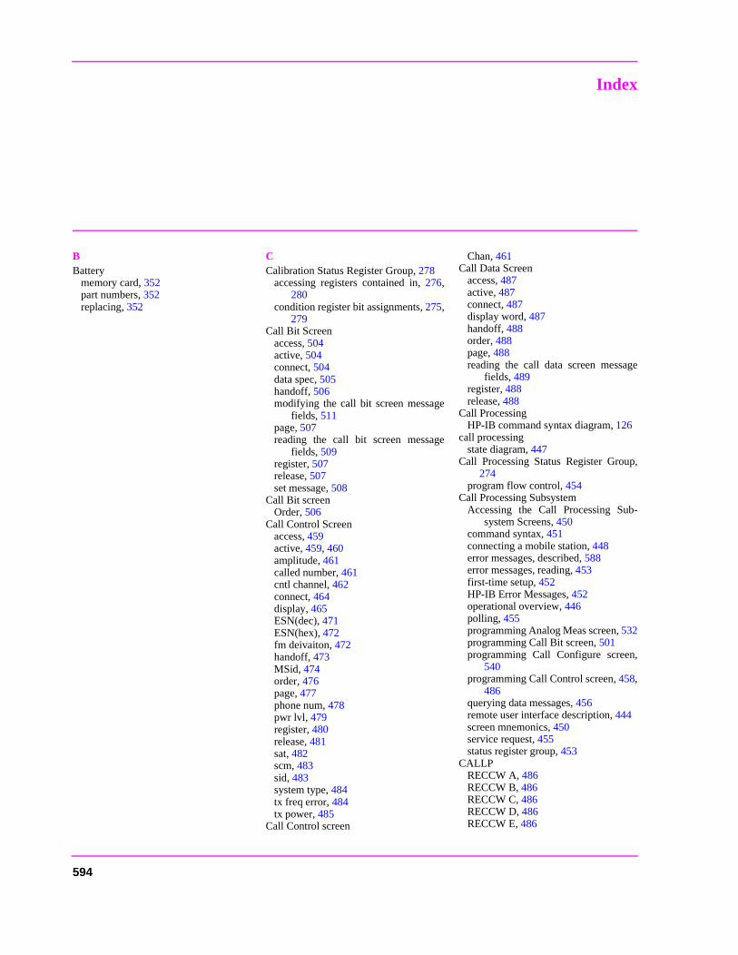
Index
BBattery
memory card, 352part numbers, 352replacing, 352
CCalibration Status Register Group, 278
accessing registers contained in, 276,280
condition register bit assignments, 275,279
Call Bit Screenaccess, 504active, 504connect, 504data spec, 505handoff, 506modifying the call bit screen message
fields, 511page, 507reading the call bit screen message
fields, 509register, 507release, 507set message, 508
Call Bit screenOrder, 506
Call Control Screenaccess, 459active, 459, 460amplitude, 461called number, 461cntl channel, 462connect, 464display, 465ESN(dec), 471ESN(hex), 472fm deivaiton, 472handoff, 473MSid, 474order, 476page, 477phone num, 478pwr lvl, 479register, 480release, 481sat, 482scm, 483sid, 483system type, 484tx freq error, 484tx power, 485
Call Control screen
Chan, 461Call Data Screen
access, 487active, 487connect, 487display word, 487handoff, 488order, 488page, 488reading the call data screen message
fields, 489register, 488release, 488
Call ProcessingHP-IB command syntax diagram, 126
call processingstate diagram, 447
Call Processing Status Register Group,274
program flow control, 454Call Processing Subsystem
Accessing the Call Processing Sub-system Screens, 450
command syntax, 451connecting a mobile station, 448error messages, described, 588error messages, reading, 453first-time setup, 452HP-IB Error Messages, 452operational overview, 446polling, 455programming Analog Meas screen, 532programming Call Bit screen, 501programming Call Configure screen,
540programming Call Control screen, 458,
486querying data messages, 456remote user interface description, 444screen mnemonics, 450service request, 455status register group, 453
CALLPRECCW A, 486RECCW B, 486RECCW C, 486RECCW D, 486RECCW E, 486
594
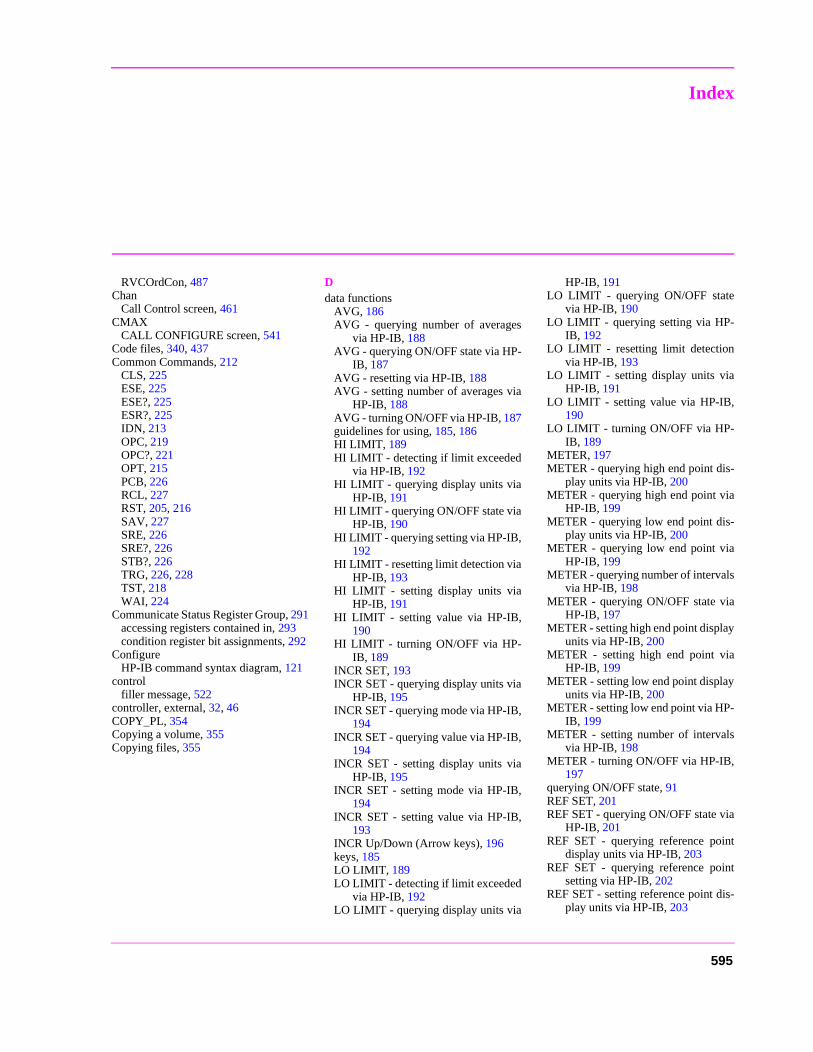
Index
RVCOrdCon, 487Chan
Call Control screen, 461CMAX
CALL CONFIGURE screen, 541Code files, 340, 437Common Commands, 212
CLS, 225ESE, 225ESE?, 225ESR?, 225IDN, 213OPC, 219OPC?, 221OPT, 215PCB, 226RCL, 227RST, 205, 216SAV, 227SRE, 226SRE?, 226STB?, 226TRG, 226, 228TST, 218WAI, 224
Communicate Status Register Group, 291accessing registers contained in, 293condition register bit assignments, 292
ConfigureHP-IB command syntax diagram, 121
controlfiller message, 522
controller, external, 32, 46COPY_PL, 354Copying a volume, 355Copying files, 355
Ddata functions
AVG, 186AVG - querying number of averages
via HP-IB, 188AVG - querying ON/OFF state via HP-
IB, 187AVG - resetting via HP-IB, 188AVG - setting number of averages via
HP-IB, 188AVG - turning ON/OFF via HP-IB, 187guidelines for using, 185, 186HI LIMIT, 189HI LIMIT - detecting if limit exceeded
via HP-IB, 192HI LIMIT - querying display units via
HP-IB, 191HI LIMIT - querying ON/OFF state via
HP-IB, 190HI LIMIT - querying setting via HP-IB,
192HI LIMIT - resetting limit detection via
HP-IB, 193HI LIMIT - setting display units via
HP-IB, 191HI LIMIT - setting value via HP-IB,
190HI LIMIT - turning ON/OFF via HP-
IB, 189INCR SET, 193INCR SET - querying display units via
HP-IB, 195INCR SET - querying mode via HP-IB,
194INCR SET - querying value via HP-IB,
194INCR SET - setting display units via
HP-IB, 195INCR SET - setting mode via HP-IB,
194INCR SET - setting value via HP-IB,
193INCR Up/Down (Arrow keys), 196keys, 185LO LIMIT, 189LO LIMIT - detecting if limit exceeded
via HP-IB, 192LO LIMIT - querying display units via
HP-IB, 191LO LIMIT - querying ON/OFF state
via HP-IB, 190LO LIMIT - querying setting via HP-
IB, 192LO LIMIT - resetting limit detection
via HP-IB, 193LO LIMIT - setting display units via
HP-IB, 191LO LIMIT - setting value via HP-IB,
190LO LIMIT - turning ON/OFF via HP-
IB, 189METER, 197METER - querying high end point dis-
play units via HP-IB, 200METER - querying high end point via
HP-IB, 199METER - querying low end point dis-
play units via HP-IB, 200METER - querying low end point via
HP-IB, 199METER - querying number of intervals
via HP-IB, 198METER - querying ON/OFF state via
HP-IB, 197METER - setting high end point display
units via HP-IB, 200METER - setting high end point via
HP-IB, 199METER - setting low end point display
units via HP-IB, 200METER - setting low end point via HP-
IB, 199METER - setting number of intervals
via HP-IB, 198METER - turning ON/OFF via HP-IB,
197querying ON/OFF state, 91REF SET, 201REF SET - querying ON/OFF state via
HP-IB, 201REF SET - querying reference point
display units via HP-IB, 203REF SET - querying reference point
setting via HP-IB, 202REF SET - setting reference point dis-
play units via HP-IB, 203
595
Index
REF SET - setting reference point viaHP-IB, 202
REF SET - turning ON/OFF via HP-IB,201
turning ON and OFF, 90using AVG via HP-IB, 186using HI LIMIT via HP-IB, 189using INCR SET via HP-IB, 193using INCR Up/Down (Arrow keys)
via HP-IB, 196using LO LIMIT via HP-IB, 189using METER via HP-IB, 197using REF SET via HP-IB, 201
Default file system, 330Detector
CALL CONFIGURE screen, 542Disk drives
external, 335, 359external - default mass storage volume
specifier, 339external - initializing media for, 359
DisplayHP-IB command syntax diagram, 149querying displayed screen via HP-IB,
208selecting screens via HP-IB, 208
Display Units, 77DOS file names, 342DOS file system, 341
initializing media for, 346restrictions, 347
Downloading programs to Test Set, 389,433
EEncoder
pre-modulation filters, 105EPSON card (see Memory card), 329,
336, 349Error Message Queue Group, 268
accessing the error message queue, 269Error messages, 563
format of, 564types of, 563
Example Programs, 543comments, 552polling example program, 554SRQ example program, 545
extended address wordorder, 525reverse control channel, 493voice channel assignment, 527
External Automatic Control Mode, 32External controller, 28, 32, 46External disk drives, 331, 335, 359
initializing media for, 346, 359
FFCC mobile station control word 2
order, 525voice channel assignment, 527
FCC mobile station control, word 1, 524File names
conflicts, 344recommendations, 345
File systembacking up files, 354copying volume, 355DOS, 341DOS file names, 342file name conflicts, 344file naming recommendations, 345file types, 346initializing media, 346, 353, 358, 359LIF, 341LIF file names, 342naming files, 342storing code files, 346
File types, 346Files
backing up, 354copying, 355storing, 346
Firmware errornon-recoverable, 571
first word of called address, 496Front panel
functions not programmable, 49ON/OFF key, 90, 184
Front panel keysCANCEL key, 184CURSOR CONTROL knob, 184ENTER key, 184HOLD key, 209HP-IB command syntax, 184k1-k5, k1’-k3’ keys, 210LOCAL key, 205MEAS RESET key, 205NO key, 184PRESET key, 205PREV key, 209PRINT key, 209RECALL key, 206SAVE key, 206SHIFT key, 184
596
Index
YES key, 184FVC mobile station control message
order, 528voice channel assignment, 530
HHardware Status Register #1 Group, 286
accessing registers contained in, 288condition register bit assignments, 287
Hardware Status Register #2 Group, 282accessing registers contained in, 284condition register bit assignments, 283
HFS (Hierarchical File System), 342Hierarchical File System (HFS), 342HP 8920A Memory Card Part Numbers,
349HP 8920B Memory Card Part Numbers,
349HP-IB
Active Controller, 45, 318, 319address - displaying, 51, 204address - factory setting, 51address - setting, 51, 204arming measurements, 235Attribute units - changing, 85Attribute units - definition, 83Attribute units - guidelines, 89Attribute units - querying, 88changing a field setting, 47Common Commands, 212Common Commands CLS, 225Common Commands ESE, 225Common Commands ESE?, 225Common Commands ESR?, 225Common Commands IDN, 213Common Commands OPC, 219Common Commands OPC?, 221Common Commands OPT, 215Common Commands PCB, 226Common Commands RCL, 227Common Commands RST, 205, 216Common Commands SAV, 227Common Commands SRE, 226Common Commands SRE?, 226Common Commands STB?, 226Common Commands TRG, 226, 228Common Commands TST, 218Common Commands WAI, 224configuration, 45display units - changing, 78display units - definition, 77display units - guidelines, 79display units - querying, 79
downloading programs to Test Set, 389error messages, 563Errors, 563, 572extended addressing, 51external (select code 7), 31, 46getting started, 36Group Execute Trigger (GET), 228HP-IB units - changing, 81HP-IB units - definition, 80HP-IB units - guidelines, 82HP-IB units - querying, 82Increasing measurement speed, 238Increasing measurement speed (see In-
creasing Measurement Speed), 238Instrument Initialization (see Instru-
ment Initialization), 305internal (select code 8), 31, 46local lockout, 57Local/Remote Triggering Changes,
231making a simple measurement, 48measurement pacing, 235multiple addressing, 51passing control (see Passing Control),
318PROGram commands (see PROGram
Subsystem), 408programming examples, 41, 47, 92programming guidelines, 38reading a field setting, 47Service requests (see Service Re-
quests), 295standards, 36STATe command - definition, 90STATe command - guidelines, 91Status reporting (see Status reporting),
244System Controller, 45, 318, 319topics covered, 37Trigger - aborting, 232Trigger commands, 232Trigger event, 228Trigger modes, 229, 233Trigger modes - affect on measurement
speed, 234, 238Trigger modes - default settings, 231Trigger modes - retriggering, 229, 233Trigger modes - settings for fastest
597
Index
measurements, 234Trigger modes - settings for most reli-
able measurements, 234Trigger modes - settling, 230, 233Triggering measurements, 228units of measure, 77uploading programs to Test Set, 390using, 27
HP-IB command syntaxACPower, 99AFANalyzer, 101AFGenerator1, 104AFGenerator2, 105, 106AUNits, 85AUNits?, 88AVERage
RESet, 188
STATe, 187
STATe?, 187
VALue, 188
VALue?, 188CALLP, 126CONFigure, 121
BADDress, 204CPRocess, 126DECoder, 145diagram structure, 96DISPlay, 149, 208DUNits, 78DUNits?, 79ENCoder, 106front panel keys, 184guidelines, 73HLIMit
DUNits, 191
DUNits?, 191
EXCeeded?, 192
RESet, 193
STATe, 189
STATe?, 190
VALue, 190
VALue?, 192
HP-IB only commands, 171INCRement, 193, 196
DIVide, 196
DUNits, 195
DUNits?, 195
MODE, 194
MODE?, 194
MULTiply, 195INCRement?, 194Integer Number Setting, 178LLIMit
DUNits, 191
DUNits?, 191
EXCeeded?, 192
RESet, 193
STATe, 189
STATe?, 190
VALue, 190
VALue?, 192MEASure, 151
RESet, 205METer
HEND, 199
DUNits, 200
DUNits?, 200
HEND?, 199
INTerval, 198
INTerval?, 198
LEND, 199
DUNits, 200
DUNits?, 200
LEND?, 199
STATe, 197
STATe?, 197Multiple Number Measurement, 183Multiple Real Number Setting, 180Number Measurement, 181
OSCilloscope, 158PROGram, 163Real Number Setting, 179REFerence
DUNits, 203
DUNits?, 203
STATe, 201
STATe?, 201
VALue, 202
VALue?, 202REGister, 164
CLEar, 207
RECall, 206
SAVE, 206RFANalyzer, 165RFGenerator, 167RINTerface, 168SANalyzer, 169SPECial, 171STATe, 90STATe?, 91STATus, 172, 173TESTs, 174TRIGger, 177
ABORt, 232
IMMediate, 232
MODE, 233UNITs, 81UNITs?, 82use of single quotes, 43use of spaces, 43, 74using colons to separate commands, 75using question mark to query setting/
field, 76using quotes for strings, 74using semicolon colon command sepa-
rator, 75, 243using semicolon to output multiple
commands, 75using upper/lower case letters, 73
HP-IB only commandsHP-IB command syntax diagram, 171
598
Index
II/O Configure
HP-IB command syntax diagram, 121IBASIC
avoiding program hangs, 42command line, 364Controller, 28, 30, 31, 46Controller - default mass storage loca-
tion, 338Controller - interfacing to using serial
ports, 368Controller architecture, 30, 31Controller screen, 363COPY command, 355copying files, 355default file system, 330EDIT mode - entering/exiting, 394error messages, 563GET command, 346INITIALIZE command, 346, 353, 358,
359initializing media, 346language, 30LOAD command, 346making a simple measurement, 48Mass Storage Volume Specifier (MSI),
353MSI, 353passing control back using PASS CON-
TROL, 321program development (see Program
Development), 365requesting HP-IB active control, 322running programs, 40SAVE command, 346selecting mass storage devices, 339STORE command, 346storing files, 346
IEEE 488.1compliance, 49, 50Interface Function Capabilities, 50Passing Control (see Passing Control),
318Remote Interface Message Capabili-
ties, 52SRQ (see Service Requests), 295
IEEE 488.2Common Commands, 212
Common Commands CLS, 225Common Commands ESE, 225, 265Common Commands ESE?, 225, 264Common Commands ESR?, 225, 262Common Commands IDN, 213Common Commands OPC, 219Common Commands OPC?, 221Common Commands OPT, 215Common Commands PCB, 226, 320Common Commands RCL, 227Common Commands RST, 205, 216Common Commands SAV, 227Common Commands SRE, 226, 298Common Commands SRE?, 226, 298Common Commands STB?, 226, 248Common Commands TRG, 226, 228Common Commands TST, 218Common Commands WAI, 224Common CommandsRST, 312compliance, 49, 50Output Queue, 266Overlapped commands, 72Sequential commands, 72Standard Event Status Register, 260Status Byte Register, 246
Increasing measurement speed, 238autoranging, 238autotuning, 238combining ENTER statements, 243combining OUTPUT statements, 242compound commands, 242measurement setup time, 241speed of control program, 242
instrument functionquerying ON/OFF state, 91turning ON and OFF, 90
Instrument Initialization, 305Device Clear (DCL) HP-IB Bus Com-
mand, 315Front panel PRESET key, 309Interface Clear (IFC) HP-IB Bus Com-
mand, 317methods of, 306power on reset, 306RST Common Command, 312Selected Device Clear (SDC) HP-IB
Bus Command, 316Integer Number Setting
HP-IB command syntax diagram, 178Internal Automatic Control Mode, 30, 33
599
Index
Kkeys
front panel, 49
LLibrary files, 437
backing up, 354LIF file names, 342LIF file system, 341
initializing media for, 346lock up
HP-IB bus, 230, 235
MManual Control Mode, 29, 33Mass Storage Devices, 329
accessing, 340default locations, 338EPSON cards, 336, 349external disk drives, 335, 359initializing media for, 346, 353, 358OTP card, 336, 349overview, 331PCMCIA cards, 336, 349RAM Disk, 333, 357ROM card, 336, 349ROM Disk, 334, 348selecting, 339SRAM card, 336, 349write protecting, 351
Mass storage locationsdefault values, 338selecting, 339
Mass Storage Volume Specifier, 353Measure
HP-IB command syntax diagram, 151measurement
active, 29, 43querying ON/OFF state, 91querying value, 29, 44, 76recommended sequence, 40turning ON and OFF, 90
Measurement speed - increasing (see In-creasing Measurement Speed), 238
Memory Cards, 329address, 353battery (see Battery), 352initializing, 346, 353inserting, 349Mass Storage Volume Specifier, 353OTP cards, 336part numbers, 349removing, 349ROM cards, 336SRAM cards, 336using, 349write-protect switch, 351
messageabbreviated address word, 524access, 517access type parameters global action,
600
Index
,
517C-FILMESS, 522control filler, 522extended address word, order, 525extended address word, voice channel
assignment, 527FCC mobile station control, word 1,
524FCC mobile station control, word 2, or-
der, 525FCC mobile station control, word 2,
voice channel assignment, 527FVC mobile station control, order, 528FVC mobile station control, voice
channel assignment, 530FVC O Mes, 528FVC V Mes, 530MS IntVCh, 527MS WORD1, 524MSMessOrd, 525RECCW A, 490RECCW B, 493RECCW C, 495RECCW D, 496RECCW E, 497REG ID, 521REG INC, 519registration identification message, 521registration increment global action,
519reverse control channel, 490reverse voice channel, 490RVCOrdCon, 498SPC Word 1, 512SPC Word 2, 514system parameter overhead, word 1,
512system parameter overhead, word 2,
514messages
error, 563Microsoft® Windows Terminal terminal
emulator, 375, 395Multiple Number Measurement
HP-IB command syntax diagram, 183Multiple Real Number Setting
HP-IB command syntax diagram, 180
NNon-Recoverable Firmware Error, 571Number Measurement
HP-IB command syntax diagram, 181
OOperating Modes
external automatic control, 28, 32internal automatic control, 28, 30, 33manual control, 28, 29, 33
Operation Status Register Group, 256accessing registers contained in, 258Condition Register bit assignments
257Order
Call Data screen, 506Oscilloscope
HP-IB command syntax diagram, 158OTP Memory card, 331, 336Output Queue Group, 266
accessing the output queue, 267Overlapped Commands, 72
601
Index
-
PPacing measurements, 235Passing Control, 318
example programs, 322passing control back automatically, 321passing control back to another control-
ler, 321passing control back using PASS CON-
TROL, 321passing control to Test Set, 320requesting control from IBASIC, 322
PCAdvanceLink (HP 68333F Version
B.02.00) terminal emulator, 379,395
Microsoft® Windows Terminal termi-nal emulator, 12, 395
ProCommr® Revision 2.4.3 terminalemulator, 12, 396
Serial Port Configuration, 374Terminal emulator, 374
PCMCIA card (see Memory card), 329,336, 349
printerconnecting to HP-IB, 45
Procedure files, 340, 438backing up, 354
ProCommr® Revision 2.4.3 terminal em-ulator, 12, 396
ProgramHP-IB command syntax diagram, 163
Program Developmentchoosing development method, 382IBASIC, 366Method #1 - Using external computer,
384Method #2 - Using IBASIC EDIT
mode, 392Method #3 - Using word processor on
PC, 397methods of, 366
program hangsavoiding, 42
PROGram Subsystem, 389, 408commands, 411executing commands, 431
QQuestionable Data/Signal Register
Group, 270accessing registers contained in, 272condition register bit assignments, 271
RRadio Interface
HP-IB command syntax diagram, 168RAM Disk, 331, 333
initializing, 358using, 357
RAM_MNG, 357Real Number Setting
HP-IB command syntax diagram, 179Recalling registers
HP-IB command syntax diagram, 164RECCW A
CALLP, 486messages, 490
RECCW BCALLP, 486messages, 493
RECCW CCALLP, 486messages, 495
RECCW DCALLP, 486messages, 496
RECCW ECALLP, 486messages, 497
RegisterHP-IB command syntax diagram, 164
registration identification message, 521registration increment global action mes
sage, 519reverse voice channel
order confirmation message, 498RF Analyzer
HP-IB command syntax diagram, 165RF Generator
HP-IB command syntax diagram, 167RJ-11 jack, 368ROM Disk, 331, 334
using, 348ROM Memory card, 331, 336RVCOrdCon
CALLP, 487messages, 498
602
Index
SSave/Recall Registers
default mass storage locations, 338Saving registers
HP-IB command syntax diagram, 164second word of called address, 497Sequential Commands, 72serial number word, 495Serial Port, 368
cables/adapters for, 369configuration, 368, 372, 405receive/transmit pacing, 373select code 10, 369, 405, 407select code 9, 369, 372, 405serial I/O from IBASIC program, 405
Service Request Enable Register, 297clearing, 299reading, 298writing, 298
Service Requests, 295enabling SRQ interrupts, 296procedure for generating, 300Service Request Enable Register (see
Service Request EnableRegister),297
setting up SRQ interrupts, 296Signaling Decoder
HP-IB command syntax diagram, 145Signaling Encoder
HP-IB command syntax diagram, 106Special
HP-IB command syntax diagram, 171Spectrum Analyzer
HP-IB command syntax diagram, 169SRAM Memory card, 331, 336SRQ (see Service Requests), 295Standard Event Status Register Group,
260accessing registers contained in, 261bit assignments, 261
StatusHP-IB command syntax diagram, 172,
173Status Byte Register, 246
bit assignments, 247, 296clearing, 249reading with serial poll, 248reading with STB Common Command,
248writing, 249
Status reporting, 244Calibration Status Register Group (see
Calibration StatusRegister Group),278
Call Processing Status Register Group,274
clearing the Status Byte Register, 249Communicate Status Register Group
(see Communicate StatusRegisterGroup), 291
Condition register definition, 251Enable register definition, 252Error Message Queue Group (see Error
Message Queue Group), 268Event register definition, 252Hardware Status Register #1 Group
(see Hardware StatusRegister #1Group), 286
Hardware Status Register #2 Group(see Hardware StatusRegister #2Group), 282
Operation Status Register Group (seeOperation StatusRegister Group),256
Output Queue Group (see OutputQueue Group), 266
Questionable Data/Signal RegisterGroup (see QuestionableData/Sig-nal Register Group), 270
reading Status Byte Register with serialpoll, 248
reading Status Byte Register with STBCommonCommand, 248
Standard Event Status Register Group(see Standard EventStatus RegisterGroup), 260
Status Byte Register, 246status queue model, 254status register model, 251status register structure overview, 250status registers in Test Set, 255status reporting structure operation,
253structure overview, 244Summary Message definition, 252Transition filter definition, 251
writing the Status Byte Register, 249Storing code files, 346System Controller, 319system parameter overhead word 2 mes-
sage, 514
603
Index
TTerminal Configuration, 381Test Set
Attribute units - changing, 85Attribute units - definition, 83Attribute units - guidelines, 89Attribute units - querying, 88default file system, 330display units - changing, 78display units - definition, 77display units - guidelines, 79display units - querying, 79file name conflicts, 344file system, 341file types, 346HP-IB units - changing, 81HP-IB units - definition, 80HP-IB units - guidelines, 82HP-IB units - querying, 82IEEE 488.1 Interface Function Capa-
bilities, 50IEEE 488.1 Remote Interface Message
Capabilities, 52initializing (see Instrument Initializa-
tion), 305instruments contained in, 29interfacing to using serial ports, 368local mode, 55, 56operating modes, 28overview, 28remote mode, 55, 56remote operation, 49STATe command - definition, 90STATe command - guidelines, 91status registers, 255units of measure, 77writing programs for, 28, 33
TestsHP-IB command syntax diagram, 174
TESTS Subsystem, 436default mass storage locations, 339DOS file restrictions, 347file descriptions, 437file relationships, 438screens, 439writing programs for, 437
TestSetfile name entry field width, 343
file names (see also DOS & LIF filenames), 343
TriggerHP-IB command syntax diagram, 177HP-IB commands, 232
Trigger - aborting, 232Trigger event, 228Trigger modes, 229, 233
affect on measurement speed, 234default settings, 231Local/Remote Triggering Changes,
231retriggering, 229, 233settings for fastest measurements, 234settings for most reliable measure-
ments, 234settling, 230, 233
Triggering measurements, 228TX Pwr Zero
CALL CONFIGURE screen, 542
UUploading programs from Test Set to ex-
ternal controller, 434Uploading programs from Test Set to PC,
404Uploading programs to Test Set, 390
604
Index
Vvoice channel assignment, 461Volume copy, 355
WWildcards, 356word
abbreviated address, 490extended address, 493first word of called address, 496reverse voice channel order confirma-
tion message, 498second word of called address, 497serial number, 495
Word processor, 397configuring for program development,
397transferring programs to Test Set, 399writing lines of IBASIC code, 398
Write-protect switch, 351
XXon/Xoff, 373
605