Embed Size (px)
Citation preview
HP 3000/iX Network Planning andConfiguration Guide
HP 3000 MPE/iX Computer Systems
Edition 4
36922-90037E1098
Printed in: U.S.A. October 1998

NoticeThe information contained in this document is subject to changewithout notice.
Hewlett-Packard makes no warranty of any kind with regard to thismaterial, including, but not limited to, the implied warranties ofmerchantability or fitness for a particular purpose. Hewlett-Packardshall not be liable for errors contained herein or for direct, indirect,special, incidental or consequential damages in connection with thefurnishing or use of this material.
Hewlett-Packard assumes no responsibility for the use or reliability ofits software on equipment that is not furnished by Hewlett-Packard.
This document contains proprietary information which is protected bycopyright. All rights reserved. Reproduction, adaptation, or translationwithout prior written permission is prohibited, except as allowed underthe copyright laws.
Restricted Rights Legend
Use, duplication, or disclosure by the U.S. Government is subject torestrictions as set forth in subparagraph (c) (1) (ii) of the Rights inTechnical Data and Computer Software clause at DFARS 252.227-7013.Rights for non-DOD U.S. Government Departments and Agencies areas set forth in FAR 52.227-19 (c) (1,2).
Acknowledgments
UNIX is a registered trademark of The Open Group.
Hewlett-Packard Company3000 Hanover StreetPalo Alto, CA 94304 U.S.A.
© Copyright 1991, 1992, 1994 and 1998 by Hewlett-Packard Company
Contents
1. Network Configuration OverviewPre-Configuration Hardware Check . . . . . . . . . . . . . . . . . . . . . . . . . . . 18Pre-Configuration Software check . . . . . . . . . . . . . . . . . . . . . . . . . . . . 19Configuration Process Overview . . . . . . . . . . . . . . . . . . . . . . . . . . . . . . 20
2. Networking ConceptsNetwork Environment Design Considerations . . . . . . . . . . . . . . . . . . 22
Line Speed. . . . . . . . . . . . . . . . . . . . . . . . . . . . . . . . . . . . . . . . . . . . . . 22Geographical Location . . . . . . . . . . . . . . . . . . . . . . . . . . . . . . . . . . . . 22
Special Cases. . . . . . . . . . . . . . . . . . . . . . . . . . . . . . . . . . . . . . . . . . 23Shared Dial Links . . . . . . . . . . . . . . . . . . . . . . . . . . . . . . . . . . . . . . 23Non-HP 3000 Nodes (Including PCs). . . . . . . . . . . . . . . . . . . . . . . 23Applicable SYSGEN Parameters . . . . . . . . . . . . . . . . . . . . . . . . . . 23Dynamic Ldevs . . . . . . . . . . . . . . . . . . . . . . . . . . . . . . . . . . . . . . . . 24
Network Interface and Link Types. . . . . . . . . . . . . . . . . . . . . . . . . . . . 25Number of Network Interfaces . . . . . . . . . . . . . . . . . . . . . . . . . . . . . 25Priority of Network Interfaces . . . . . . . . . . . . . . . . . . . . . . . . . . . . . . 26
Subnetworks. . . . . . . . . . . . . . . . . . . . . . . . . . . . . . . . . . . . . . . . . . . . . . 27Why Use Subnets? . . . . . . . . . . . . . . . . . . . . . . . . . . . . . . . . . . . . . . . 27
How Subnetting Works . . . . . . . . . . . . . . . . . . . . . . . . . . . . . . . . . . 27Assigning Subnet Masks . . . . . . . . . . . . . . . . . . . . . . . . . . . . . . . . 27
Internetworks. . . . . . . . . . . . . . . . . . . . . . . . . . . . . . . . . . . . . . . . . . . . . 31Gateways. . . . . . . . . . . . . . . . . . . . . . . . . . . . . . . . . . . . . . . . . . . . . . . 31
Full Gateways versus Gateway Halves . . . . . . . . . . . . . . . . . . . . . 31Gateway Configuration Overview . . . . . . . . . . . . . . . . . . . . . . . . . . . 32
Identifying Neighbor Gateways . . . . . . . . . . . . . . . . . . . . . . . . . . . 32Neighbor Gateway Examples . . . . . . . . . . . . . . . . . . . . . . . . . . . . . 32Configuring a Gateway Half Pair. . . . . . . . . . . . . . . . . . . . . . . . . . 33
Address Resolution . . . . . . . . . . . . . . . . . . . . . . . . . . . . . . . . . . . . . . . . 35Domain Name Services . . . . . . . . . . . . . . . . . . . . . . . . . . . . . . . . . . . 35Network Directory . . . . . . . . . . . . . . . . . . . . . . . . . . . . . . . . . . . . . . . 35
When a Network Directory is Required. . . . . . . . . . . . . . . . . . . . . 36Planning the Network Directory . . . . . . . . . . . . . . . . . . . . . . . . . . 36Copying and Merging Network Directory Files . . . . . . . . . . . . . . 37
Probe and Probe Proxy . . . . . . . . . . . . . . . . . . . . . . . . . . . . . . . . . . . . 38Address Resolution Protocol (ARP) . . . . . . . . . . . . . . . . . . . . . . . . . . 38
Enabling Probe and ARP . . . . . . . . . . . . . . . . . . . . . . . . . . . . . . . . 38Network Design Questions . . . . . . . . . . . . . . . . . . . . . . . . . . . . . . . . . . 39Software Configuration Maximums . . . . . . . . . . . . . . . . . . . . . . . . . . . 41
3. Planning Your NetworkDrawing an Internetwork Map . . . . . . . . . . . . . . . . . . . . . . . . . . . . . . . 44
Communication Between Networks . . . . . . . . . . . . . . . . . . . . . . . . . 45Network Boundaries. . . . . . . . . . . . . . . . . . . . . . . . . . . . . . . . . . . . . . 46IP Network Addresses . . . . . . . . . . . . . . . . . . . . . . . . . . . . . . . . . . . . 46
Completing the Internetwork Table . . . . . . . . . . . . . . . . . . . . . . . . . . . 47Drawing a Network Map . . . . . . . . . . . . . . . . . . . . . . . . . . . . . . . . . . . . 48Network Worksheets . . . . . . . . . . . . . . . . . . . . . . . . . . . . . . . . . . . . . . . 49
3
Contents
LAN Network Worksheets . . . . . . . . . . . . . . . . . . . . . . . . . . . . . . . . . 49LAN Network Map . . . . . . . . . . . . . . . . . . . . . . . . . . . . . . . . . . . . . 49LAN Network Table . . . . . . . . . . . . . . . . . . . . . . . . . . . . . . . . . . . . 50LAN Internet Routing Table . . . . . . . . . . . . . . . . . . . . . . . . . . . . . 51
Token Ring Network Worksheets . . . . . . . . . . . . . . . . . . . . . . . . . . . 51FDDI Network Worksheets . . . . . . . . . . . . . . . . . . . . . . . . . . . . . . . . 51100VG-AnyLAN Network Worksheets . . . . . . . . . . . . . . . . . . . . . . . 51100Base-T Network Worksheets . . . . . . . . . . . . . . . . . . . . . . . . . . . . 51Point-to-Point Network Worksheets . . . . . . . . . . . . . . . . . . . . . . . . . 52
Point-to-Point Network Map . . . . . . . . . . . . . . . . . . . . . . . . . . . . . 52Point-to-Point Network Table. . . . . . . . . . . . . . . . . . . . . . . . . . . . . 53Point-to-Point Internet Routing Table . . . . . . . . . . . . . . . . . . . . . . 53
X.25 Network Worksheets . . . . . . . . . . . . . . . . . . . . . . . . . . . . . . . . . 55X.25 Network Map . . . . . . . . . . . . . . . . . . . . . . . . . . . . . . . . . . . . . 55X.25 Network Table . . . . . . . . . . . . . . . . . . . . . . . . . . . . . . . . . . . . 56X.25 Internet Routing Table. . . . . . . . . . . . . . . . . . . . . . . . . . . . . . 56
Gateway Half Pair Worksheets . . . . . . . . . . . . . . . . . . . . . . . . . . . . . 57Gateway Half Map . . . . . . . . . . . . . . . . . . . . . . . . . . . . . . . . . . . . . 57Gateway Half Network Interface Table . . . . . . . . . . . . . . . . . . . . . 58
Network Directory Worksheet. . . . . . . . . . . . . . . . . . . . . . . . . . . . . . . . 59
4. Planning for Node ConfigurationNode Worksheet Information . . . . . . . . . . . . . . . . . . . . . . . . . . . . . . . . 62
LAN Configuration Worksheet . . . . . . . . . . . . . . . . . . . . . . . . . . . . . 69Token Ring Configuration Worksheet . . . . . . . . . . . . . . . . . . . . . . . . 70FDDI Configuration Worksheet . . . . . . . . . . . . . . . . . . . . . . . . . . . . . 71100VG-AnyLAN Configuration Worksheet . . . . . . . . . . . . . . . . . . . . 72100Base-T Configuration Worksheet. . . . . . . . . . . . . . . . . . . . . . . . . 73Point-to-Point Configuration Worksheet . . . . . . . . . . . . . . . . . . . . . . 74X.25 Configuration Worksheet. . . . . . . . . . . . . . . . . . . . . . . . . . . . . . 75X.25 Virtual Circuit Configuration Worksheet . . . . . . . . . . . . . . . . . 76
Neighbor Gateway Worksheet Information . . . . . . . . . . . . . . . . . . . . . 77Neighbor Gateway Configuration Worksheet . . . . . . . . . . . . . . . . . . 78
Neighbor Gateway Reachable networks Worksheet Information . . . . 79Neighbor Gateway Reachable Networks Configuration Worksheet 80
5. Introductory ScreensTo Begin the Configuration Process . . . . . . . . . . . . . . . . . . . . . . . . . . . 82
To Start NMMGR . . . . . . . . . . . . . . . . . . . . . . . . . . . . . . . . . . . . . . . . 82To Open the Configuration File . . . . . . . . . . . . . . . . . . . . . . . . . . . . . 82To Select NS Configuration . . . . . . . . . . . . . . . . . . . . . . . . . . . . . . . . 85To Select Guided Configuration . . . . . . . . . . . . . . . . . . . . . . . . . . . . . 87Guided/Unguided Configuration . . . . . . . . . . . . . . . . . . . . . . . . . . . . 87To Perform Guided Network Transport Configuration . . . . . . . . . . 88
4
Contents
6. Configuring a LAN, Token Ring, FDDI, 100VG-AnyLAN, 100Base-TNode
To Configure a LAN Network Interface . . . . . . . . . . . . . . . . . . . . . . . . 93To Configure a Token Ring Network Interface. . . . . . . . . . . . . . . . . . . 98To Configure an FDDI Network Interface . . . . . . . . . . . . . . . . . . . . . 102To Configure a 100VG-AnyLAN Network Interface . . . . . . . . . . . . . 106To Configure a 100Base-T Network Interface . . . . . . . . . . . . . . . . . . 110To Configure Neighbor Gateways . . . . . . . . . . . . . . . . . . . . . . . . . . . . 115
To Identify Neighbor Gateways (If Any Are Present). . . . . . . . . . . 115To Identify Neighbor Gateway Reachable Networks . . . . . . . . . . . 117
7. Configuring a Point-to-Point NodeTo Configure a Point-to-Point Network Interface . . . . . . . . . . . . . . . 123To Configure Neighbor Gateways . . . . . . . . . . . . . . . . . . . . . . . . . . . . 127
To Identify Neighbor Gateways (If Any Are Present). . . . . . . . . . . 127To Identify Neighbor Gateway Reachable Networks . . . . . . . . . . . 129
To Configure Node Mapping . . . . . . . . . . . . . . . . . . . . . . . . . . . . . . . . 131To Select a Node Mapping Screen . . . . . . . . . . . . . . . . . . . . . . . . . . 131To Configure Shared Dial Node Mapping . . . . . . . . . . . . . . . . . . . . 132To Configure Direct Connect/Dial Node Mapping . . . . . . . . . . . . . 134
8. Configuring an X.25 NodeTo Configure an X.25 Network Interface . . . . . . . . . . . . . . . . . . . . . . 139
To Configure X.25 Virtual Circuits . . . . . . . . . . . . . . . . . . . . . . . . . 142To Configure Neighbor Gateways . . . . . . . . . . . . . . . . . . . . . . . . . . . . 147
To Identify Neighbor Gateways (If Any Are Present). . . . . . . . . . . 147To Identify Neighbor Gateway Reachable Networks . . . . . . . . . . . 148
9. Configuring a Gateway HalfTo Configure a Gatehalf Network Interface . . . . . . . . . . . . . . . . . . . . 153
10. Validating Network Transport and Cross-Validating with SYSGENTo Validate the Network Transport . . . . . . . . . . . . . . . . . . . . . . . . . . 158To Cross-Validate in SYSGEN . . . . . . . . . . . . . . . . . . . . . . . . . . . . . . 159
11. Configuring the Network DirectoryTo Open the Network Directory . . . . . . . . . . . . . . . . . . . . . . . . . . . . . 162To Select the Update Directory Function . . . . . . . . . . . . . . . . . . . . . . 164To Add Nodes to the Network Directory File . . . . . . . . . . . . . . . . . . . 166To Configure Path Report Data for a Node. . . . . . . . . . . . . . . . . . . . . 169
12. Configuring Domain Name FilesTo Create or Modify the Resolver File . . . . . . . . . . . . . . . . . . . . . . . . 174To Create or Modify the Hosts File . . . . . . . . . . . . . . . . . . . . . . . . . . . 176
5
Contents
Additional Domain Name Configuration Files. . . . . . . . . . . . . . . . . . 178Network Name Database . . . . . . . . . . . . . . . . . . . . . . . . . . . . . . . . . 178Protocol Name Database . . . . . . . . . . . . . . . . . . . . . . . . . . . . . . . . . 178Service Name Database . . . . . . . . . . . . . . . . . . . . . . . . . . . . . . . . . . 178
13. Configuring LoggingTo Access the Logging configuration Screens. . . . . . . . . . . . . . . . . . . 181To Modify the Logging Configuration . . . . . . . . . . . . . . . . . . . . . . . . . 182To Enable Users for Individual Logging Classes . . . . . . . . . . . . . . . . 191To Activate Logging . . . . . . . . . . . . . . . . . . . . . . . . . . . . . . . . . . . . . . . 193
14. Operating the NetworkTo Start Links and Services . . . . . . . . . . . . . . . . . . . . . . . . . . . . . . . . 196
To Start Software Loopback. . . . . . . . . . . . . . . . . . . . . . . . . . . . . . . 196To Start a Link . . . . . . . . . . . . . . . . . . . . . . . . . . . . . . . . . . . . . . . . . 196
To Start a Host-Based X.25 Link . . . . . . . . . . . . . . . . . . . . . . . . . 196To Start the Network Services. . . . . . . . . . . . . . . . . . . . . . . . . . . . . 197
To Test the Network Services . . . . . . . . . . . . . . . . . . . . . . . . . . . . . . . 198To Shut Down the Network Services . . . . . . . . . . . . . . . . . . . . . . . . . 199
A. MPE/V to MPE/iX MigrationDifferences Between NS 3000/V and NS 3000/iX . . . . . . . . . . . . . . . 202
Differences in the Network . . . . . . . . . . . . . . . . . . . . . . . . . . . . . . . 202Differences in Configuration Files . . . . . . . . . . . . . . . . . . . . . . . . . . 202Differences in Applications Support . . . . . . . . . . . . . . . . . . . . . . . . 203Difference in How to Obtain Status Information . . . . . . . . . . . . . . 203
Migration Overview . . . . . . . . . . . . . . . . . . . . . . . . . . . . . . . . . . . . . . . 204Before You Start . . . . . . . . . . . . . . . . . . . . . . . . . . . . . . . . . . . . . . . . 204File Migration Tasks . . . . . . . . . . . . . . . . . . . . . . . . . . . . . . . . . . . . 204Additional Migration Considerations . . . . . . . . . . . . . . . . . . . . . . . 204
File Conversion Guidelines . . . . . . . . . . . . . . . . . . . . . . . . . . . . . . . . . 205When you Need to Convert Files . . . . . . . . . . . . . . . . . . . . . . . . . . . 205To Convert Files . . . . . . . . . . . . . . . . . . . . . . . . . . . . . . . . . . . . . . . . 205To Update From a Previous MPE/iX Version . . . . . . . . . . . . . . . . . 207
Reconfiguration Guidelines . . . . . . . . . . . . . . . . . . . . . . . . . . . . . . . . . 208
B. NS X.25 Migration: NS 3000/XL Releases 1.0, 1.1, or 1.2 to NS 3000/iXRelease 2.0 or Later
To Convert NS 3000/XL 1.X to 2.0 Files . . . . . . . . . . . . . . . . . . . . . . . 210
C. NS X.25 Migration: NS 3000/V to NS 3000/iX Release 2.0 or LaterDifferences Between NS 3000/V and NS 3000/iX . . . . . . . . . . . . . . . 212
Differences in Hardware . . . . . . . . . . . . . . . . . . . . . . . . . . . . . . . . . 212Unsupported Network Connections. . . . . . . . . . . . . . . . . . . . . . . . . 212Differences in Configuration of Terminals and Printers . . . . . . . . 212Differences in Configuration Files . . . . . . . . . . . . . . . . . . . . . . . . . . 213Differences in Network Services . . . . . . . . . . . . . . . . . . . . . . . . . . . 213To Obtain Device Status Information . . . . . . . . . . . . . . . . . . . . . . . 213
6
Contents
Differences in X.25 Support . . . . . . . . . . . . . . . . . . . . . . . . . . . . . . . . 2141980 Versus 1984 CCITT . . . . . . . . . . . . . . . . . . . . . . . . . . . . . . . . . 214General Level 3 Differences . . . . . . . . . . . . . . . . . . . . . . . . . . . . . . . 214Level 3 Access with NetIPC . . . . . . . . . . . . . . . . . . . . . . . . . . . . . . . 214Facilities . . . . . . . . . . . . . . . . . . . . . . . . . . . . . . . . . . . . . . . . . . . . . . 215Security . . . . . . . . . . . . . . . . . . . . . . . . . . . . . . . . . . . . . . . . . . . . . . . 215Pad Support . . . . . . . . . . . . . . . . . . . . . . . . . . . . . . . . . . . . . . . . . . . 216
To Convert NS 3000/V Files to NS 3000/iX Release 2.0 or Later . . . 217To Delete Secondary NIs (NS/iX Rel. 2.2 or later) . . . . . . . . . . . . . 217
To Save NS 3000/V X.25 Parameters . . . . . . . . . . . . . . . . . . . . . . . . . 218To Copy NS 3000/V Configuration Files to NS 3000/iX System . . . . 219To Use NMMGRVER . . . . . . . . . . . . . . . . . . . . . . . . . . . . . . . . . . . . . . 220
To Update X.25 XL System Access Parameters . . . . . . . . . . . . . . . 220To Save X.25 XL System Access Parameters on the Host . . . . . . . 221To Add Other Link Types as Needed. . . . . . . . . . . . . . . . . . . . . . . . 221To Verify DTS Configuration on the Host . . . . . . . . . . . . . . . . . . . . 221
To Configure the DTC . . . . . . . . . . . . . . . . . . . . . . . . . . . . . . . . . . . . . 222
D. NS X.25 Migration: NS 3000/V and NS 3000/XL Release 1.X to iXRelease 2.0 or later
Differences Between NS 3000/V and NS 3000/iX . . . . . . . . . . . . . . . 224Differences in Hardware . . . . . . . . . . . . . . . . . . . . . . . . . . . . . . . . . 224Unsupported Network Connections. . . . . . . . . . . . . . . . . . . . . . . . . 224Differences in Configuration of Terminals and Printers . . . . . . . . 224Differences in Configuration Files . . . . . . . . . . . . . . . . . . . . . . . . . . 225Differences in Network Services . . . . . . . . . . . . . . . . . . . . . . . . . . . 225To Obtain Device Status Information . . . . . . . . . . . . . . . . . . . . . . . 225
Differences in X.25 Support . . . . . . . . . . . . . . . . . . . . . . . . . . . . . . . . 2261980 vs. 1984 CCITT . . . . . . . . . . . . . . . . . . . . . . . . . . . . . . . . . . . . 226General Level 3 Differences . . . . . . . . . . . . . . . . . . . . . . . . . . . . . . . 226Level 3 Access with NetIPC . . . . . . . . . . . . . . . . . . . . . . . . . . . . . . . 226Facilities . . . . . . . . . . . . . . . . . . . . . . . . . . . . . . . . . . . . . . . . . . . . . . 227Security . . . . . . . . . . . . . . . . . . . . . . . . . . . . . . . . . . . . . . . . . . . . . . . 227PAD Support . . . . . . . . . . . . . . . . . . . . . . . . . . . . . . . . . . . . . . . . . . . 228
To Convert MPE V-Based Server Files to NS 3000/iX Release 2.0 or later229To Delete Secondary NIs (NS/XL Release 2.2 or later) . . . . . . . . . . . 230To Save NS 3000/V X.25 Parameters . . . . . . . . . . . . . . . . . . . . . . . . . 231To Copy NS 3000/V Configuration Files to NS 3000/iX System . . . . 232To Use NMMGRVER . . . . . . . . . . . . . . . . . . . . . . . . . . . . . . . . . . . . . . 233
To Update X.25 XL System Access Parameters . . . . . . . . . . . . . . . 233To Save X.25 XL System Access Parameters on the Host . . . . . . . 234To Add Other Link Types as Needed. . . . . . . . . . . . . . . . . . . . . . . . 234To Verify DTS Configuration on the Host . . . . . . . . . . . . . . . . . . . . 234
To Configure the DTC . . . . . . . . . . . . . . . . . . . . . . . . . . . . . . . . . . . . . 235
7

Contents
E. NS X.25 Migration: NS 3000/V PAD Access to NS 3000/iX Release 2.0or Later
Differences Between NS3000/V and NS3000/iX PAD Support . . . . . 238To Migrate from NS 3000/V PAD Access to NS 3000/iX Release 2.0 or later239
If You are Using Host-Based Network Management . . . . . . . . . . . 239If You are Using PC-Based Network Management . . . . . . . . . . . . 239To Save NS 3000/V PAD Parameters . . . . . . . . . . . . . . . . . . . . . . . 239PAD Access Migration Categories . . . . . . . . . . . . . . . . . . . . . . . . . . 240
Non-Nailed Devices. . . . . . . . . . . . . . . . . . . . . . . . . . . . . . . . . . . . 240Nailed Devices. . . . . . . . . . . . . . . . . . . . . . . . . . . . . . . . . . . . . . . . 240Configuration of Nailed Versus Non-Nailed Devices . . . . . . . . . 240
To Save DTS Parameters on the Host . . . . . . . . . . . . . . . . . . . . . . . 241To Configure the DTC. . . . . . . . . . . . . . . . . . . . . . . . . . . . . . . . . . . . 241
Glossary
Index
8
Figures
Figure 2-1 . Class C Address with Subnet Number (Example 1) . . . . . . . . . . . . . . . . . . . . . . . . . . . .28Figure 2-2 . Class C Address with Subnet Number (Example 2) . . . . . . . . . . . . . . . . . . . . . . . . . . . .29Figure 2-3 . Gateway Configuration Scenarios. . . . . . . . . . . . . . . . . . . . . . . . . . . . . . . . . . . . . . . . . . .33Figure 3-1 . Internetwork Map . . . . . . . . . . . . . . . . . . . . . . . . . . . . . . . . . . . . . . . . . . . . . . . . . . . . . . .45Figure 3-2 . LAN Network Map. . . . . . . . . . . . . . . . . . . . . . . . . . . . . . . . . . . . . . . . . . . . . . . . . . . . . . .50Figure 3-3 . Point-to-Point Network Map . . . . . . . . . . . . . . . . . . . . . . . . . . . . . . . . . . . . . . . . . . . . . . .52Figure 3-4 . X.25 Network Map. . . . . . . . . . . . . . . . . . . . . . . . . . . . . . . . . . . . . . . . . . . . . . . . . . . . . . .55Figure 3-5 . Gateway-Half Map. . . . . . . . . . . . . . . . . . . . . . . . . . . . . . . . . . . . . . . . . . . . . . . . . . . . . . .58Figure 4-1 . LAN Configuration . . . . . . . . . . . . . . . . . . . . . . . . . . . . . . . . . . . . . . . . . . . . . . . . . . . . . .69Figure 4-2 . Token Ring Configuration . . . . . . . . . . . . . . . . . . . . . . . . . . . . . . . . . . . . . . . . . . . . . . . . .70Figure 4-3 . FDDI Configuration. . . . . . . . . . . . . . . . . . . . . . . . . . . . . . . . . . . . . . . . . . . . . . . . . . . . . .71Figure 4-4 . 100VG-AnyLAN Configuration . . . . . . . . . . . . . . . . . . . . . . . . . . . . . . . . . . . . . . . . . . . . .72Figure 4-5 . 100Base-T Configuration. . . . . . . . . . . . . . . . . . . . . . . . . . . . . . . . . . . . . . . . . . . . . . . . . .73Figure 4-6 . Point-to-Point Configuration . . . . . . . . . . . . . . . . . . . . . . . . . . . . . . . . . . . . . . . . . . . . . . .74Figure 4-7 . X.25 Configuration. . . . . . . . . . . . . . . . . . . . . . . . . . . . . . . . . . . . . . . . . . . . . . . . . . . . . . .75Figure 4-8 . X.25 Virtual Circuit Configuration . . . . . . . . . . . . . . . . . . . . . . . . . . . . . . . . . . . . . . . . . .76Figure 4-9 . Neighbor Gateway Configuration . . . . . . . . . . . . . . . . . . . . . . . . . . . . . . . . . . . . . . . . . . .78Figure 4-10 . Reachable Network Configuration . . . . . . . . . . . . . . . . . . . . . . . . . . . . . . . . . . . . . . . . .80Figure 5-1 . NMMGR Screen Flow . . . . . . . . . . . . . . . . . . . . . . . . . . . . . . . . . . . . . . . . . . . . . . . . . . . .81Figure 5-2 . Open Configuration/Directory File Screen . . . . . . . . . . . . . . . . . . . . . . . . . . . . . . . . . . . .83Figure 5-3 . Main Screen . . . . . . . . . . . . . . . . . . . . . . . . . . . . . . . . . . . . . . . . . . . . . . . . . . . . . . . . . . . .85Figure 5-4 . NS Configuration Screen. . . . . . . . . . . . . . . . . . . . . . . . . . . . . . . . . . . . . . . . . . . . . . . . . .87Figure 5-5 . Network Transport Configuration Screen . . . . . . . . . . . . . . . . . . . . . . . . . . . . . . . . . . . .88Figure 6-1 . Configuring Screen Flow . . . . . . . . . . . . . . . . . . . . . . . . . . . . . . . . . . . . . . . . . . . . . . . . . .91Figure 6-2 . LAN Configuration Screen . . . . . . . . . . . . . . . . . . . . . . . . . . . . . . . . . . . . . . . . . . . . . . . .93Figure 6-3 . Token Ring Configuration Screen . . . . . . . . . . . . . . . . . . . . . . . . . . . . . . . . . . . . . . . . . . .98Figure 6-4 . FDDI Configuration Screen. . . . . . . . . . . . . . . . . . . . . . . . . . . . . . . . . . . . . . . . . . . . . . .102Figure 6-5 . 100VG-AnyLAN Configuration Screen. . . . . . . . . . . . . . . . . . . . . . . . . . . . . . . . . . . . . .106Figure 6-6 . 100Base-T Configuration Screen . . . . . . . . . . . . . . . . . . . . . . . . . . . . . . . . . . . . . . . . . .110Figure 6-7 . Neighbor Gateways Screen . . . . . . . . . . . . . . . . . . . . . . . . . . . . . . . . . . . . . . . . . . . . . . .116Figure 6-8 . Neighbor Gateway Reachable Networks Screen . . . . . . . . . . . . . . . . . . . . . . . . . . . . . .117Figure 7-1 . Point-to-Point Link Configuration Screen Flow. . . . . . . . . . . . . . . . . . . . . . . . . . . . . . .121Figure 7-2 . Point-to-Point Link Configuration Screen . . . . . . . . . . . . . . . . . . . . . . . . . . . . . . . . . . .123Figure 7-3 . Neighbor Gateway Screen . . . . . . . . . . . . . . . . . . . . . . . . . . . . . . . . . . . . . . . . . . . . . . . .128Figure 7-4 . Neighbor Gateway Reachable Networks . . . . . . . . . . . . . . . . . . . . . . . . . . . . . . . . . . . .129Figure 7-5 . Shared Dial Node Mapping Configuration Screen. . . . . . . . . . . . . . . . . . . . . . . . . . . . .132Figure 7-6 . Direct Connect/Dial Node Mapping Configuration Screen . . . . . . . . . . . . . . . . . . . . . .135Figure 7-7 . Using an @ for Mapping Non-Adjacent Nodes . . . . . . . . . . . . . . . . . . . . . . . . . . . . . . . .136Figure 8-1 . X.25 Link Screen Flow. . . . . . . . . . . . . . . . . . . . . . . . . . . . . . . . . . . . . . . . . . . . . . . . . . .137Figure 8-2 . NS Configuration Screen. . . . . . . . . . . . . . . . . . . . . . . . . . . . . . . . . . . . . . . . . . . . . . . . .139Figure 8-3 . X.25 Virtual Circuit Configuration Screen. . . . . . . . . . . . . . . . . . . . . . . . . . . . . . . . . . .143Figure 8-4 . Neighbor Gateways Screen . . . . . . . . . . . . . . . . . . . . . . . . . . . . . . . . . . . . . . . . . . . . . . .148Figure 8-5 . Neighbor Gateway Reachable Networks Screen . . . . . . . . . . . . . . . . . . . . . . . . . . . . . .149Figure 9-1 . Gateway Half Link Screen Flow . . . . . . . . . . . . . . . . . . . . . . . . . . . . . . . . . . . . . . . . . . .151Figure 9-2 . Gatehalf Configuration Screen . . . . . . . . . . . . . . . . . . . . . . . . . . . . . . . . . . . . . . . . . . . .153Figure 11-1 . Network Directory Configuration Screen Flow . . . . . . . . . . . . . . . . . . . . . . . . . . . . . .161Figure 11-2 . Open Configuration/Directory File . . . . . . . . . . . . . . . . . . . . . . . . . . . . . . . . . . . . . . . .162Figure 11-3 . Network Directory Main . . . . . . . . . . . . . . . . . . . . . . . . . . . . . . . . . . . . . . . . . . . . . . . .164Figure 11-4 . Network Directory Select Node Name . . . . . . . . . . . . . . . . . . . . . . . . . . . . . . . . . . . . .166
9
Figures
Figure 11-5 . Network Directory Data . . . . . . . . . . . . . . . . . . . . . . . . . . . . . . . . . . . . . . . . . . . . . . . .169Figure 12-1 . Sample Resolver Configuration File . . . . . . . . . . . . . . . . . . . . . . . . . . . . . . . . . . . . . . .175Figure 12-2 . Sample Hosts Configuration File . . . . . . . . . . . . . . . . . . . . . . . . . . . . . . . . . . . . . . . . .177Figure 13-1 . Logging Configuration Screen Flow . . . . . . . . . . . . . . . . . . . . . . . . . . . . . . . . . . . . . . .179Figure 13-2 . Netxport Log Configuration (1) Screen. . . . . . . . . . . . . . . . . . . . . . . . . . . . . . . . . . . . .182Figure 13-3 . Netxport Log Configuration (2) Screen. . . . . . . . . . . . . . . . . . . . . . . . . . . . . . . . . . . . .183Figure 13-4 . Netxport Log Configuration (3) Screen. . . . . . . . . . . . . . . . . . . . . . . . . . . . . . . . . . . . .185Figure 13-5 . Netxport Log Configuration (4) Screen. . . . . . . . . . . . . . . . . . . . . . . . . . . . . . . . . . . . .186Figure 13-6 . Netxport Log Configuration (5) Screen. . . . . . . . . . . . . . . . . . . . . . . . . . . . . . . . . . . . .187Figure 13-7 . Netxport Log Configuration (6) Screen. . . . . . . . . . . . . . . . . . . . . . . . . . . . . . . . . . . . .189Figure 13-8 . Logging Configuration: Class Data Screen . . . . . . . . . . . . . . . . . . . . . . . . . . . . . . . . .191
10
Tables
Table 2-1. Valid Addresses of Example Subnetwork . . . . . . . . . . . . . . . . . . . . . . . . . . . . . . . . . . . . . .30Table 2-2. Configuration Maximums. . . . . . . . . . . . . . . . . . . . . . . . . . . . . . . . . . . . . . . . . . . . . . . . . . .41Table 3-1. Internetwork Table . . . . . . . . . . . . . . . . . . . . . . . . . . . . . . . . . . . . . . . . . . . . . . . . . . . . . . . .47Table 3-2. LAN Network Table . . . . . . . . . . . . . . . . . . . . . . . . . . . . . . . . . . . . . . . . . . . . . . . . . . . . . . .50Table 3-3. LAN Internet Routing Table . . . . . . . . . . . . . . . . . . . . . . . . . . . . . . . . . . . . . . . . . . . . . . . .51Table 3-4. Point-to-Point Network Table . . . . . . . . . . . . . . . . . . . . . . . . . . . . . . . . . . . . . . . . . . . . . . .53Table 3-5. Point-to-Point Internet Routing Table. . . . . . . . . . . . . . . . . . . . . . . . . . . . . . . . . . . . . . . . .54Table 3-6. X.25 Network Table . . . . . . . . . . . . . . . . . . . . . . . . . . . . . . . . . . . . . . . . . . . . . . . . . . . . . . .56Table 3-7. X.25 Internet Routing Table . . . . . . . . . . . . . . . . . . . . . . . . . . . . . . . . . . . . . . . . . . . . . . . .57Table 3-8. Gateway Half Network Interface Table. . . . . . . . . . . . . . . . . . . . . . . . . . . . . . . . . . . . . . . .58Table 3-9. Network Directory Information Table . . . . . . . . . . . . . . . . . . . . . . . . . . . . . . . . . . . . . . . . .59Table 4-1. Configuration Worksheet Information. . . . . . . . . . . . . . . . . . . . . . . . . . . . . . . . . . . . . . . . .62Table 11-1. Path Type Configuration . . . . . . . . . . . . . . . . . . . . . . . . . . . . . . . . . . . . . . . . . . . . . . . . .172Table 13-1. Subsystem Activation/Deactivation. . . . . . . . . . . . . . . . . . . . . . . . . . . . . . . . . . . . . . . . .193


1 Network Configuration Overview
This manual provides step-by-step instructions you can use to configurean HP 3000 node for network communications. You can use theinformation to configure an IEEE 802.3/Ethernet, Token Ring, FDDI,100VG-AnyLAN, 100Base-T, Point-to-Point (router), or X.25 node.
Before you begin configuration, you must ensure your network isphysically set up and ready for network configuration.
This chapter provides information you should know before you beginconfiguration. It tells you what preparations you must make and whatitems you will be configuring.
This chapter contains the following configuration information:
• Pre-configuration hardware check.
• Pre-configuration software check.
• Configuration process overview.
17

Network Configuration OverviewPre-Configuration Hardware Check
Pre-Configuration Hardware CheckHardware Check Before you begin the actual configuration process,check that the hardware components required for NS 3000/iX havebeen installed and verified according to the procedures in the hardwareinstallation manuals listed in the preface to this guide.
18 Chapter 1
Network Configuration OverviewPre-Configuration Software check
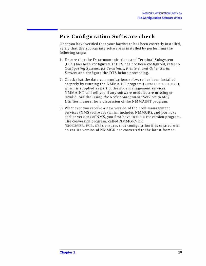
Pre-Configuration Software checkOnce you have verified that your hardware has been correctly installed,verify that the appropriate software is installed by performing thefollowing steps:
1. Ensure that the Datacommunications and Terminal Subsystem(DTS) has been configured. If DTS has not been configured, refer toConfiguring Systems for Terminals, Printers, and Other SerialDevices and configure the DTS before proceeding.
2. Check that the data communications software has been installedproperly by running the NMMAINT program (NMMAINT.PUB.SYS),which is supplied as part of the node management services.NMMAINT will tell you if any software modules are missing orinvalid. See the Using the Node Management Services (NMS)Utilities manual for a discussion of the NMMAINT program.
3. Whenever you receive a new version of the node managementservices (NMS) software (which includes NMMGR), and you haveearlier versions of NMS, you first have to run a conversion program.The conversion program, called NMMGRVER(NMMGRVER.PUB.SYS), ensures that configuration files created withan earlier version of NMMGR are converted to the latest format.
Chapter 1 19
Network Configuration OverviewConfiguration Process Overview
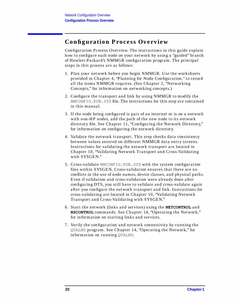
Configuration Process OverviewConfiguration Process Overview. The instructions in this guide explainhow to configure each node on your network by using a “guided” branchof Hewlett-Packard’s NMMGR configuration program. The principalsteps in this process are as follows:
1. Plan your network before you begin NMMGR. Use the worksheetsprovided in Chapter 4, “Planning for Node Configuration,” to recordall the items NMMGR requires. (See Chapter 2, “NetworkingConcepts,” for information on networking concepts.)
2. Configure the transport and link by using NMMGR to modify theNMCONFIG.PUB.SYSfile. The instructions for this step are containedin this manual.
3. If the node being configured is part of an internet or is on a networkwith non-HP nodes, add the path of the new node to its networkdirectory file. See Chapter 11, “Configuring the Network Directory,”for information on configuring the network directory.
4. Validate the network transport. This step checks data consistencybetween values entered on different NMMGR data entry screens.Instructions for validating the network transport are located inChapter 10, “Validating Network Transport and Cross-Validatingwith SYSGEN.”
5. Cross-validate NMCONFIG.PUB.SYS with the system configurationfiles within SYSGEN. Cross-validation ensures that there are noconflicts in the use of node names, device classes, and physical paths.Even if validation and cross-validation were already done afterconfiguring DTS, you still have to validate and cross-validate againafter you configure the network transport and link. Instructions forcross-validating are located in Chapter 10, “Validating NetworkTransport and Cross-Validating with SYSGEN.”
6. Start the network (links and services) using the NETCONTROL andNSCONTROL commands. See Chapter 14, “Operating the Network,”for information on starting links and services.
7. Verify the configuration and network connectivity by running theQVALNS program. See Chapter 14, “Operating the Network,” forinformation on running QVALNS.
20 Chapter 1
2 Networking Concepts
Planning a network or internetwork (collection of networks) is animportant process that must be done with care to ensure that thenetwork meets the needs of your organization. Many factors must betaken into consideration when planning the network or internetwork:for example, volume of usage over particular links, volume of CPUusage of each node, physical layout needs and limitations (such asgeographical distances), and desirability of connections tonon-NS 3000/iX nodes.
This chapter provides information to help you design your network andplan for configuration using NMMGR. The following network designelements are discussed:
• Design considerations of the network environment.
• Network interface and link types.
• Subnetworks.
• Internetworks.
• Address resolution methods.
• Domain names.
• Network design questions.
• Probe and probe proxy.
• Address Resolution Protocol (ARP).
• Network directory.
21
Networking ConceptsNetwork Environment Design Considerations
Network Environment DesignConsiderationsNetwork and internetwork design must take many factors intoconsideration: the desired physical location of the computerscomprising the network, the volume of projected communications trafficbetween nodes, communications traffic patterns, and the possibility ofconnections to other types of nodes (such as those in a public datanetwork) are just some of the criteria to consider.
These factors will affect your choice of NS network type (LAN, TokenRing, FDDI, 100VG-AnyLAN, 100Base-T, Point-to-Point, X.25) as wellas choice of specific links. They will also affect how you design yournetwork layout. You may want to create subnetworks within yournetwork by configuring IP subnet addresses. You may, on the otherhand, need to join several networks together to form an internetworkor internet.
Line SpeedLine Speed is a measure of the rate at which data is transmitted by aphysical link (usually measured in kilobits or megabits per second). Themaximum line speed varies among different NS links. Line speed maytherefore influence your choice of link. Although line speed does notindicate the exact throughput of a particular link, it can be used on acomparative basis to indicate relative throughput.
In general, an IEEE 802.3/Ethernet LAN or Token Ring network will befaster than a Point-to-Point or X.25 network because the bus or ringtopology provides a faster routing mechanism than a series ofPoint-to-Point hops. FDDI, 100VG-AnyLAN, and 100Base-T links willbe an order of magnitude faster than LAN or Token Ring. Links usingleased lines will have a higher line speed than links using normaltelephone lines.
Consult your Hewlett-Packard representative for line speeds and themost up-to-date performance data for various links.
Geographical LocationThe geographical location of the computers that will be part of yournetwork or internet will be an important factor in deciding both thephysical topology and the link types that you should use.
If all of the nodes you want to connect are located relatively close toeach other (in the same building, for example) you might choose toconnect them via a LAN, Token Ring link, 100VG-AnyLAN, or100Base-T.
22 Chapter 2
Networking ConceptsNetwork Environment Design Considerations
Another option for nodes located in the same geographic location is touse hardwired (direct-connect) Point-to-Point links. You might wish touse a Point-to-Point network if the distance between some nodes on thenetwork will be greater than the maximum distance allowed betweennodes on a LAN.
FDDI networks also offer greater distances than LAN, Token Ring,100VG-AnyLAN, or 100Base-T networks. FDDI networks can be up to200 kilometers in length, with nodes up to 2 kilometers apart.
If you need to connect nodes that are geographically distant (forexample, HP 3000s located in different cities) you might choose toconnect them via a dial link. For NS dial links, you can use thePoint-to-Point 3000/iX Network Link.
Finally, if you need to use satellite transmission because of the largegeographical distance between nodes, or if you need to have access toother nodes on a public or private X.25 network, you might wish to usethe DTC/X.25 iX Network Link.
Special CasesThe following sections describe certain design requirements for specialsituations, such as shared dial links, personal computers, and usingnon-HP 3000 minicomputers on an NS network.
Shared Dial LinksShared dial links have two limitations that must be considered whendesigning a network. First, a shared dial link cannot be used as anintermediate link in a Point-to-Point network. Any other kind of diallink can be used for intermediate links, but shared dial links can beused only to connect leaf nodes (that is, nodes that receive messagestargeted only for themselves, also referred to as end nodes). Second,shared dial links cannot be used as gateway halves.
Non-HP 3000 Nodes (Including PCs)LAN, Token Ring, FDDI, 100VG-AnyLAN, 100Base-T, and X.25networks can access non-HP 3000 nodes. Point-to-Point networks mustbe composed of only HP 3000s.
Applicable SYSGEN ParametersVT terminals are not physical devices, instead they are virtual devicescreated dynamically at remote logon, header entries are created for themaximum number of VT terminals at system boot time. The exactnumber of head entries created for VT terminals will depend on thevalue of MAXDYNIO (which is configurable in SYSGEN).
The exact number of remote sessions which can be supported on a givensystem will depend on the exact mix of jobs and sessions (remote andlocal, active and inactive) on that system.
Chapter 2 23
Networking ConceptsNetwork Environment Design Considerations
The maximum number of concurrent processes may limit the number ofremote logons before the maximum number of dynamic I/O devicesdoes.
Dynamic LdevsThis is actually a system parameter that can be configured to 999 inSYSGEN. The default is 332, but the actual number that can be in usemay be limited by the IDD/ODD limits. VT and NS use one dynamicldev per remote session and one per LAN link and one perPoint-to-Point link.
NOTE The result of having DYNAMIC IO DEVS configured too low for NSVIRTUAL TERMINAL connections is VTERR 8 or VT INFORM 050.
Likewise the dynamic I/O device limit may be reached before theconcurrent process limit.
24 Chapter 2
Networking ConceptsNetwork Interface and Link Types
Network Interface and Link TypesThe network interface (NI), the software that provides an interfacebetween a node and a network, specifies the type and maximumnumber of links that can be configured for a node. Because a node’snetwork interface determines what links can be configured for the node,links are said to be configured underneath network interfaces.
There are nine types of network interfaces (in addition to loopback):
• LAN for IEEE 802.3 and Ethernet networks.
• Token Ring for IEEE 802.5 networks.
• FDDI for fiber optic networks.
• 100VG-AnyLAN for 100VG-AnyLAN networks.
• 100Base-T for 100Base-T networks.
• Point-to-Point for networks that use Point-to-Point routing.
• X.25 for X.25 networks.
• NS over SNA is no longer offered as a product and has beenremoved from the Corporate Price List. The product is obsolete withno plans for support.
• Gateway half for nodes that function as gateway halves.
Number of Network InterfacesA system can have up to 12 network interfaces (NI) configured. One ofthese network interfaces must be loopback. For each network interface,the maximum number of links you can configure and the kinds of linkspossible are determined by the network interface type, as follows:
• A LAN network interface can have only one link configured under it;however, a single link can reach a large number of nodes. ThickLANcable supports up to 100 nodes per segment; ThinLAN cable can beused for up to 30 nodes per segment; and each Ethertwist 3000/iXcan be used for up to 50 nodes. Up to two LAN NIs can be activeat a time per system.
• A Token Ring interface can have only one link configured under it;however, a single link can reach a large number of nodes. Token Ring3000/iX Network Link can support up to 250 nodes per ring usingshielded twisted pair (STP) cabling at 4 or 16 Mbps and 50 nodes perring using unshielded twisted pair (UTP) cabling at 4 Mbps. Onlyone Token Ring NI can be active at a time per system.
Chapter 2 25

Networking ConceptsNetwork Interface and Link Types
• An FDDI interface can have only one link configured under it;however, a single link can reach a large number of nodes. FDDI/iXNetwork Link can support up to 1000 nodes. Up to four FDDI NIscan be active at a time per system.
• A Point-to-Point network interface can have up to 40 linksconfigured under it. Point-to-Point links may be dial links, in whicha modem attached to a node is used to transmit and receive datacarried across telephone wires, or leased lines, in which data is sentover data-grade lines leased from a private carrier. Up to 11Point-to-Point NI’s can be active at a time (one NI must beloopback) for a total of 12 NI’s per system.
• An X.25 network interface can have from one to 11 links configured,depending on the number of configured X.25 network interfaces onthe node. (A single node can have up to 11 NIs and up to 11 X.25links.) Each link can be connected to as many as 1,024 remote nodes,with communication allowed with as many as 256 nodes at the sametime. Up to 11 X.25 NI’s can be active at a time (one NI must beloopback) for a total of 12 NI’s per system.
• A gateway half network interface can have only one link configuredunder it (the gateway half link). Links connecting two gatewayhalves can be only NS Point-to-Point 3000/iX Network links. Onlyone gateway half NI can be active at a time per system.
If more than one (non-loopback) network interface is configured on anode, the network portions of the IP addresses configured for theinterfaces should differ to correspond to the multiple networks to whichthe node belongs.
Refer to “Software Configuration Maximums” at the end of this chapterfor information on configuration path maximums.
Priority of Network InterfacesIf it is possible to reach a destination through more than one active NI,the network determines which NI to select according to the followingpriority:
loopback
100VG-AnyLAN
100BASE-T
FDDI
LAN
Token Ring
X.25
Gateway Half
Point-to-Point (router)
If more than one NI of a given type is active, (for example, two X.25NIs) the network will select the one that it finds first.
26 Chapter 2

Networking ConceptsSubnetworks
SubnetworksIP Subnets are used to divide one network into two or more distinctsubnetworks. Subnet numbers identify subnetworks in the same waythat network addresses identify physically distinct networks.Subnetting divides the node address portion of an IP address into twoportions—one for identifying a specific subnetwork and one foridentifying a node on that subnetwork.
Why Use Subnets?The use of subnets is optional. Subnets are typically used inorganizations that have a large number of computers. You may wanttwo or more physically distinct networks to share the same networkaddress. This may occur, for example, if your organization has acquiredonly one network number, but any of the following is true:
• A few nodes on a single network create the bulk of the networktraffic and you want to isolate those nodes on a subnetwork to reduceoverall congestion.
• You have a single LAN and have reached the limit of its technologyin terms of node numbers or cable length.
• LANs are located too far apart to be joined with bridges.
How Subnetting WorksYou may use subnets to divide your current network into subnetworkswithout informing remote networks about an internal change inconnectivity. A packet will be routed to the proper subnet when itarrives at the gateway node. However, if you want a remote node toknow about only some of the subnets on your network, this must beconfigured.
The network portion of an IP address must be the same for eachsubnetwork of the same network. The subnet portion of an IP addressmust be the same for each node on the same subnetwork.
Assigning Subnet MasksBefore you can determine subnet numbers, you first must determinewhich bits of the node address will be used to contain your subnetnumbers.
The bits that you designate for subnet identifiers compose the subnetmask. The subnet mask is configured with NMMGR. The remainingpart of the node address is used to identify the host portion of the IPaddress.
Chapter 2 27
Networking ConceptsSubnetworks
The following rules apply when choosing a subnet mask and an IPaddress:
• Although any bits in the node address can be used as the subnetmask, Hewlett-Packard recommends aligning the subnet mask alongbyte boundaries, adjacent to the network number.
• Although standards allow subnets on the same network to havedifferent subnet masks, Hewlett-Packard recommends that youassign the same subnet mask to all subnets on a network.
• Do not assign an IP address where the network address and/or nodeaddress bits are all off (all 0s) or all on (all 1s). Likewise, the subnetaddress bits cannot be all 0s or all 1s.
To determine the subnet mask, you first need to estimate the number ofnetworks required and the number of nodes on each subnet. Allowenough bits for both nodes and subnets, as described in example 1.
Example 1
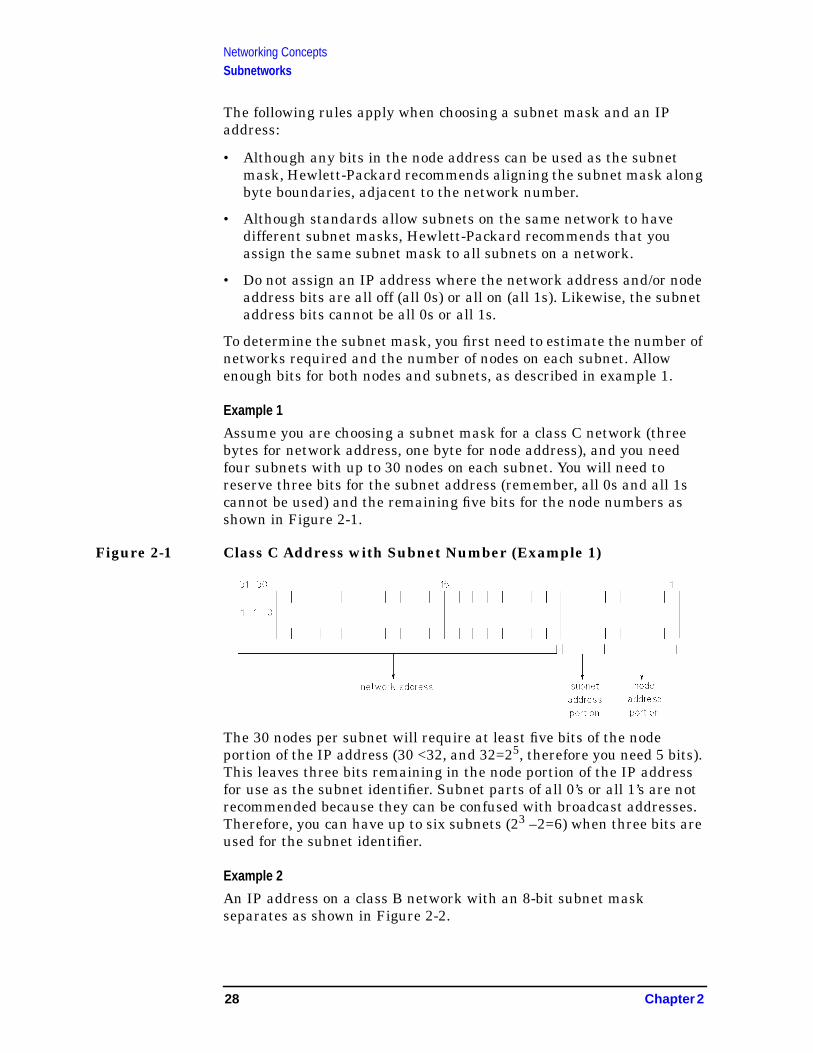
Assume you are choosing a subnet mask for a class C network (threebytes for network address, one byte for node address), and you needfour subnets with up to 30 nodes on each subnet. You will need toreserve three bits for the subnet address (remember, all 0s and all 1scannot be used) and the remaining five bits for the node numbers asshown in Figure 2-1.
Figure 2-1 Class C Address with Subnet Number (Example 1)
The 30 nodes per subnet will require at least five bits of the nodeportion of the IP address (30 <32, and 32=25, therefore you need 5 bits).This leaves three bits remaining in the node portion of the IP addressfor use as the subnet identifier. Subnet parts of all 0’s or all 1’s are notrecommended because they can be confused with broadcast addresses.Therefore, you can have up to six subnets (23 –2=6) when three bits areused for the subnet identifier.
Example 2
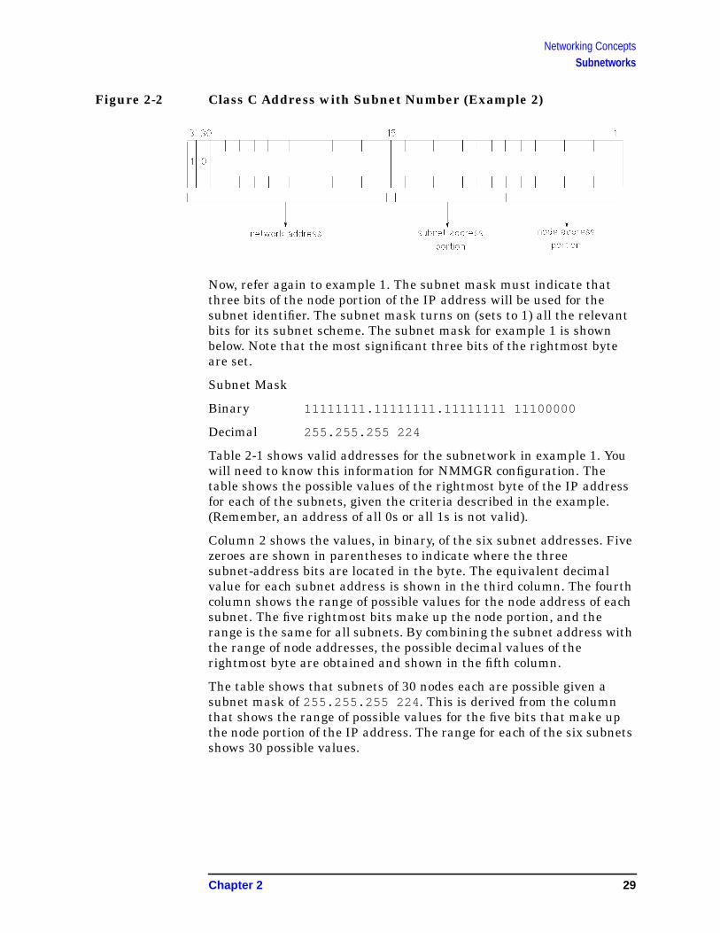
An IP address on a class B network with an 8-bit subnet maskseparates as shown in Figure 2-2.
28 Chapter 2
Networking ConceptsSubnetworks
Figure 2-2 Class C Address with Subnet Number (Example 2)
Now, refer again to example 1. The subnet mask must indicate thatthree bits of the node portion of the IP address will be used for thesubnet identifier. The subnet mask turns on (sets to 1) all the relevantbits for its subnet scheme. The subnet mask for example 1 is shownbelow. Note that the most significant three bits of the rightmost byteare set.
Subnet Mask
Binary 11111111.11111111.11111111 11100000
Decimal 255.255.255 224
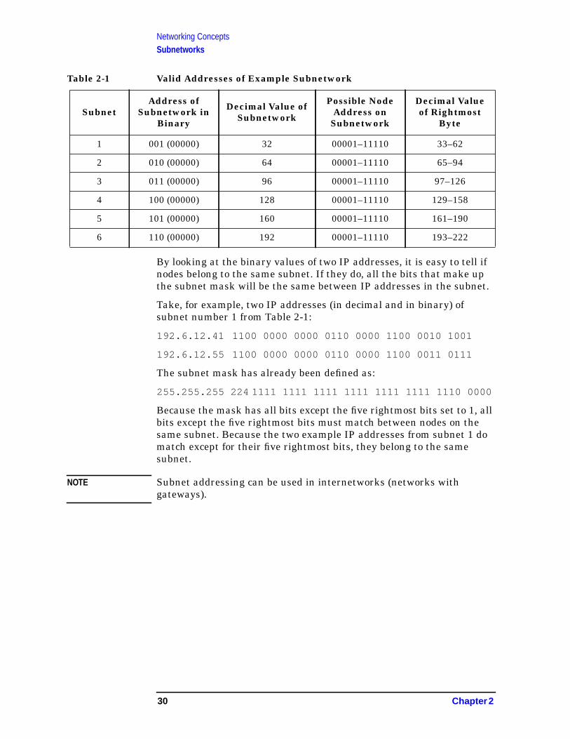
Table 2-1 shows valid addresses for the subnetwork in example 1. Youwill need to know this information for NMMGR configuration. Thetable shows the possible values of the rightmost byte of the IP addressfor each of the subnets, given the criteria described in the example.(Remember, an address of all 0s or all 1s is not valid).
Column 2 shows the values, in binary, of the six subnet addresses. Fivezeroes are shown in parentheses to indicate where the threesubnet-address bits are located in the byte. The equivalent decimalvalue for each subnet address is shown in the third column. The fourthcolumn shows the range of possible values for the node address of eachsubnet. The five rightmost bits make up the node portion, and therange is the same for all subnets. By combining the subnet address withthe range of node addresses, the possible decimal values of therightmost byte are obtained and shown in the fifth column.
The table shows that subnets of 30 nodes each are possible given asubnet mask of 255.255.255 224 . This is derived from the columnthat shows the range of possible values for the five bits that make upthe node portion of the IP address. The range for each of the six subnetsshows 30 possible values.
Chapter 2 29
Networking ConceptsSubnetworks
Table 2-1 Valid Addresses of Example Subnetwork
By looking at the binary values of two IP addresses, it is easy to tell ifnodes belong to the same subnet. If they do, all the bits that make upthe subnet mask will be the same between IP addresses in the subnet.
Take, for example, two IP addresses (in decimal and in binary) ofsubnet number 1 from Table 2-1:
192.6.12.41 1100 0000 0000 0110 0000 1100 0010 1001
192.6.12.55 1100 0000 0000 0110 0000 1100 0011 0111
The subnet mask has already been defined as:
255.255.255 224 1111 1111 1111 1111 1111 1111 1110 0000
Because the mask has all bits except the five rightmost bits set to 1, allbits except the five rightmost bits must match between nodes on thesame subnet. Because the two example IP addresses from subnet 1 domatch except for their five rightmost bits, they belong to the samesubnet.
NOTE Subnet addressing can be used in internetworks (networks withgateways).
SubnetAddress of
Subnetwork inBinary
Decimal Value ofSubnetwork
Possible NodeAddress on
Subnetwork
Decimal Valueof Rightmost
Byte
1 001 (00000) 32 00001–11110 33–62
2 010 (00000) 64 00001–11110 65–94
3 011 (00000) 96 00001–11110 97–126
4 100 (00000) 128 00001–11110 129–158
5 101 (00000) 160 00001–11110 161–190
6 110 (00000) 192 00001–11110 193–222
30 Chapter 2

Networking ConceptsInternetworks
InternetworksTwo or more networks of the same type or of different types can belinked together to form an internetwork or internet. For example, if youwanted to connect the nodes in a Point-to-Point network with the nodeson a LAN, the combination of the two networks would be called aninternetwork. Creation of an internetwork allows any node on onenetwork to communicate with any node on another network that is partof the same internetwork. Up to 256 individual networks can belong tothe same NS internetwork.
The divisions between the networks in an internetwork are callednetwork boundaries. Nodes in each network will have the samenetwork address (network portion of the IP address); however, eachnetwork within the internetwork will have its own unique networkaddress.
The networks in an internetwork may be connected by a bridge orrouter, or by HP 3000 Series 900 systems configured as gateways.
GatewaysOne method of joining networks in an internetwork is by usinggateways. An HP 3000 system can have up to 14 gateways (combinednumber of full gateways and gateway halves).
Full Gateways versus Gateway HalvesNS 3000/iX allows you to choose between connecting two networks witha full gateway or connecting them with two gateway halves. A fullgateway is a node configured as a full member of two (or more)networks for the purpose of passing information between the networksto which it belongs. The node is considered a member of each of thenetworks for which it is configured.
A node that is a gateway half is configured as a member of a networkand as a partner of another gateway half. A gateway half link that joinstwo networks connects two nodes (a gateway half pair) by aPoint-to-Point link (NS Point-to-Point 3000/iX Network link). Thegateway half link and pair is not considered a network itself. Each ofthe paired gateway halves is configured as a member of a differentnetwork (the two networks to be connected) and as a gateway half onthe same gateway half link. Together, the two gateway halves functionas a full gateway.
Chapter 2 31

Networking ConceptsInternetworks
Gateway Configuration OverviewGateway configuration includes both identifying neighbor gateways ineach node’s configuration file and configuring gateway half NIs fornodes that will serve as one half of a gateway half pair. These tasks aredescribed as follows.
Identifying Neighbor GatewaysIf you are including gateways in your internet configuration, you maywant to modify each node’s configuration file so that the node is awareof all of its neighbor gateways (gateways on the same link). Youaccomplish this during configuration of each network interface forwhich you want to allow communications over the gateway. You willfind step-by-step instructions for identifying neighbor gateways in eachof the link configuration sections of this manual.
An alternative to identifying neighbor gateways in every node’sconfiguration file is to configure a default gateway for the node.Instructions for doing so are included in this manual.
The next pages show several examples of gateway configuration.
Neighbor Gateway ExamplesWhen using NMMGR to configure any node, you will be entering theidentities of all the neighbor gateways into the configuration of thenode. The following examples illustrate several gateway configurationscenarios based on the network represented in Figure 2-3.
• Example 1: The node you are configuring may be a non-gateway,such as node D in Figure 2-3. You would need to enter the identitiesof each of its neighbor gateways, in this case nodes C and E, at theNeighbor Gateways screen. On the Neighbor Gateway ReachableNetworks screen, you would also enter the IP addresses of networks1 and 3 as two of the configured reachable networks reachablethrough gateway node C.
• Example 2: The node you are configuring may be a gateway half,such as node E in Figure 2-3. You will still need to enter theidentities of the node’s neighbor gateways as you configure the NI (inthis case, node C is the neighbor gateway). You will also need toconfigure a gateway half NI for the node, as described under“Configuring a Gateway-Half Pair.”
• Example 3: The node you are configuring may be a full gateway,such as nodes B and C in Figure 2-3. Though full gateways are neveractually identified as such in the configuration process, they too,must know about the other gateways. If you were configuringnode C, you would identify nodes B and E and neighbor gateways.
32 Chapter 2

Networking ConceptsInternetworks
• Example 4: One of the gateways on your internetwork may bedesignated as a default gateway, such as node C in Figure 2-3. Adefault gateway is a gateway that is designated to receive any trafficfor which the network is unable to identify a destination. You mustidentify the node as a default gateway in the configuration file ofeach node that will access it as the default gateway. If you wereconfiguring node D, you would identify node C as a default gatewayby entering an at sign (@) in one of the IP address fields of theNeighbor Gateway Reachable Networks screen. Only one gatewaymay be designated as a default gateway for each node. The defaultgateway must be on a LAN or Token Ring network.
Configuring a Gateway Half PairIf you are configuring a gateway half pair, you will need to configure agateway half NI for each half of the gateway pair. You will findstep-by-step instructions for configuring a gateway half NI in thismanual.
In Figure 2-3, nodes E and F form a gateway half pair. When youconfigure a node as a gateway half, you enter its partner’s IP addressinto this gateway half ’s configuration in the Gatehalf Configurationscreen. If you were to configure node E in the figure, you would enterthe IP address of node F.
Figure 2-3 Gateway Configuration Scenarios
Chapter 2 33

Networking ConceptsInternetworks
Gateway halves require the configuration of two separate networkinterfaces on each node: one for the gateway half, the other for thenetwork it interfaces to (for example, a LAN or Point-to-Point NI). Youwill need to follow the instructions for the specific NI type, dependingon the network type) and then follow the instructions to enterconfiguration items specific to the gateway half NI.
Worksheets that will aid you in planning for internetworkcommunication are located in Chapter 4, “Planning for NodeConfiguration.”
34 Chapter 2
Networking ConceptsAddress Resolution
Address ResolutionAddress resolution in NS networks refers to the mapping of node namesto IP addresses and the mapping of IP addresses to lower leveladdresses (such as an X.25 address or a station address). Severaladdress resolution methods are available for you to use individually orin combination with each other. You can configure these methodsaccording to the needs of your network.
The available address resolution methods are:
• Domain name services.
• Network directory.
• Probe (and probe proxy) (LAN, 100VG-AnyLAN, and 100Base-Tonly).
• Address resolution protocol (ARP) (LAN, Token Ring, FDDI,100VG-AnyLAN, and 100Base-T only).
Domain Name ServicesThe domain name services are a mechanism for resolving node namesto IP addresses. They conform to an open networking standard and willfacilitate communications between HP 3000 Series 900 systems as wellas with non-HP 3000 nodes.
To use the domain name services, you must assign a name, inARPANET standard format, to each system on the network orinternetwork. You configure this name on the NS Configuration screen(see configuration chapters for details).
You will also need to create a set of ASCII files on each system whichcontain the addressing information the system will need. Instructionsfor creating these files are in Chapter 12, “Configuring Domain NameFiles.”
Once you have configured the domain name services, the network willbe able to access the node using its domain name and the domain nameservice routines will resolve the domain name to the node’s IP address.
NOTE Domain name services provide name to IP address resolution only. If alower level address is required for network communication (forexample, an X.25 address) you will need to configure the networkdirectory as well.
Network DirectoryThe network directory is a set of files that contain information used bythe node to communicate with other nodes in the internetwork.
Chapter 2 35

Networking ConceptsAddress Resolution
You use NMMGR to perform the following network directory functions:
• Add, modify, and delete entries in the directory.
• Review and inspect directory information.
• Merge a remote directory with a directory on the local node.
• Automatically update directories on a group of remote nodes byusing a background stream job controlled from a centraladministrative node.
See Chapter 11, “Configuring the Network Directory,” for moreinformation on configuring the network directory through NMMGR.More information on merging directories and on central administrativenodes is included in this chapter.
When a Network Directory is RequiredA network directory must be configured in the following circumstances:
• nodes running on X.25
• nodes not using domain name services
• nodes on a LAN network that do not support the HP-PROBEprotocol
The network directory of a node in a Point-to-Point network mustcontain the IP addresses of all other nodes that you want the node to beable to reach.
When configuring the network directory for a Point-to-Point network,make sure that the IP address you enter in the network directorymatches the data in the mapping screens (path nameNETXPORT.NI. NIname.MAPPING.mapentry ).
For nodes on an X.25 network, the network directory maps the X.25address key to an IP address to allow a node to communicate within theX.25 network. You must configure a network directory for nodes usingX.25.
Planning the Network DirectoryThere are two theories about how network directories should beplanned and configured on a network, as follows:
• Centralized network directories.
• Decentralized network directories.
The centralized theory requires each node on the internet to have thesame network directory. This means that every node in the networkmust have an entry in the network directory. The advantage to this is
36 Chapter 2

Networking ConceptsAddress Resolution
that you update the network directory in one place, then copy it to therest of the world. The disadvantage is that network directories for largeinternets are going to be large.
The recommended way to create and maintain your network directoryusing the centralized method is to assign a single node as the centraladministrative node. You configure the network directory on this nodeand then copy it to all other nodes on the network. When the networkdirectory is updated, it is updated on the central administrative node,then copied to the other nodes. This procedure decreases the possibilityof incompatible directories. You may want to assign a centraladministrative node for each network or for the entire internet.
The decentralized theory suggests that each network directory beconfigured individually on each node. The advantage to this is that youcan customize the network directory on each node for security purposesusing local and global entries. The network directory will also besmaller because it will only contain entries for that particular node.However, updates must be done manually on each node.
Copying and Merging Network Directory FilesThe first time you configure the network directory, an entry for allremote IP addresses must be added manually using the NMMGRscreens. After the first network directory is configured, you can use theMPE STORE and RESTORE commands to copy the network directory toother nodes. (This is assuming you have adopted the centralizedmethod of network directory maintenance. If you use the decentralizedmethod, you must always use NMMGR to create and maintain thenetwork directory.)
NOTE The network directory uses a KSAM file pair. Therefore, when copying adirectory, be sure to copy both the data file and the key file. The systemnames the key file automatically using the first six letters of thenetwork directory file name appended with a K. For example,NSDIRK.NET.SYS is the name of the key file associated with the datafile NSDIR.NET.SYS .
Once a network directory has been established on each node in theinternet, you can set up a job stream to automate network directoryupdates. The MERGEDIR command is part of a maintenance interfaceprovided primarily to support the updating of directories using a batchjob. Using this method, a job or series of jobs can be scheduled atregular intervals to copy and then merge remote directories into thelocal-system directory. See the MERGEDIR and the MAKESTREAMcommands in Using the Node Management Services (NMS) Utilities.
Chapter 2 37
Networking ConceptsAddress Resolution
Probe and Probe ProxyNS 3000 LAN, 100VG-AnyLAN, and 100Base-T NIs with theIEEE 802.3 protocol enabled are able to make use of a proprietary HPprotocol called probe. Probe makes it possible for nodes on an NSIEEE 802.3 LAN, 100VG-AnyLAN, and 100Base-T to communicatewithout a network directory or domain names. A node can determineconnection information about a node on the same LAN by sending amulticast probe request out on the network. The target node recognizesits address in the probe request and sends an individually addressedprobe reply with the necessary connection information to therequesting node. The probe request/reply mechanism is sufficient toobtain connection requirements within a network.
If the nodes on that LAN are to communicate with other networks, atleast one node on the network must have a network directory. The nodewith the network directory is called a proxy server. By using theprobe protocol, a node without a network directory can multicast arequest for an internet address from the proxy server. For backuppurposes, you should designate at least two nodes to be proxy servers.
Address Resolution Protocol (ARP)HP 3000 LAN, Token Ring, FDDI, 100VG-AnyLAN, AND 100Base-TNIs are able to make use of a standard protocol called AddressResolution Protocol (ARP). ARP provides IP address to station addressresolution. ARP is enabled when the Ethernet protocol or Token Ring isenabled.
Enabling Probe and ARPWith the concurrent configuration of IEEE 802.3 and Ethernet on anetwork, both the probe and ARP protocols are also enabled. Bothprotocols broadcast requests to all nodes on the network to resolve theaddress of a given remote node.
If you disable IEEE 802.3 on a LAN NI, you also disable the probeprotocol. Likewise, by disabling Ethernet, you disable the ARP protocolassociated with it. You cannot disable both of these protocolssimultaneously; at least one must be active to facilitate networkcommunications.
38 Chapter 2
Networking ConceptsNetwork Design Questions
Network Design QuestionsAsk yourself the following questions to make sure your design adheresto the considerations mentioned above:
1. Are all of the nodes in the network within roughly 550 meters ofeach other?
If so, consider connecting them with ThinLAN 3000/iX links. Themaximum cable length for segments of ThinLAN 3000/iX cable is185 meters, with a maximum of three segments connected byrepeaters.
2. Are all of the nodes in the network within roughly 1,500 meters ofeach other?
If so, consider connecting them with ThickLAN (thick coaxial cable).The maximum cable length for each segment of ThickLAN coaxialcable is 500 meters, with a maximum of three segments connectedby repeaters.
3. Are all of the nodes in the network located within 2 kilometers ofeach other?
If so, consider using FDDI/iX links. The maximum cable length foreach segment is 2 kilometers with a maximum network length of upto 200 kilometers.
4. Are nodes located at remote sites? (For example, in differentbuildings in the same city, or in different cities?)
If so, consider installing an X.25 network or a Point-to-Point networkusing dial links or leased lines. Choose leased lines if you have acritical need for clear transmission or if the volume of data to betransmitted is relatively large.
5. Is the set of nodes you wish to connect composed of some nodes thatare in close proximity to one another (for example, in the samebuilding) and other nodes that are geographically distanced (forexample, in different buildings or different cities)?
If so, you may wish to use ThinLAN 3000/iX, Token Ring 3000/iX,FDDI, 100VG-AnyLAN, or 100Base-T networks for nodes that arelocated near one another and Point-to-Point or X.25 links for nodesin different buildings or cities.
6. Will HP 9000s or other minicomputers need to be part of thenetwork?
If so, consider ThinLAN 3000/iX (or its ThickLAN option),Token Ring 3000/iX, FDDI/iX, 100VG-AnyLAN, 100Base-T, orX.25/iX System Access.
Chapter 2 39
Networking ConceptsNetwork Design Questions
7. Do you need access to nodes on public or private X.25 networks?
If so, consider using DTC/X.25 iX Network Links.
8. Is a subset of nodes either geographically or organizationallydistanced from another subset of nodes?
If so, you may wish to establish a network boundary between themin order to make them two separate networks joined by a fullgateway or router. Alternatively, you may want to use subnets todivide one network into two or more physically distinct subnetworks.
9. If you must use a gateway half, is the partner-gateway half in thesame building or further away?
If the two gateway halves are in the same building, you can use adirect connect link between them. If the two gateway halves arefurther away, you will need to use a dial link.
40 Chapter 2
Networking ConceptsSoftware Configuration Maximums
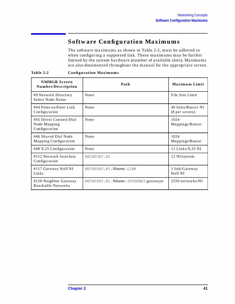
Software Configuration MaximumsThe software maximums as shown in Table 2-2, must be adhered towhen configuring a supported link. These maximums may be furtherlimited by the system hardware (number of available slots). Maximumsare also documented throughout the manual for the appropriate screen.
Table 2-2 Configuration Maximums
NMMGR ScreenNumber/Description Path Maximum Limit
#9 Network DirectorySelect Node Name
None File Size Limit
#44 Point-to-Point LinkConfiguration
None 40 links/Router NI(8 per screen)
#45 Direct Connect/DialNode MappingConfiguration
None 1024Mappings/Router
#46 Shared Dial NodeMapping Configuration
None 1024Mappings/Router
#48 X.25 Configuration None 11 Links/X.25 NI
#112 Network InterfaceConfiguration
NETXPORT.NI 12 NI/system
#117 Gateway Half NILinks
NETXPORT.NI. NIname.LINK 1 link/GatewayHalf NI
#158 Neighbor GatewayReachable Networks
NETXPORT.NI. NIname.INTERNET .gatewayn 2550 networks/NI
Chapter 2 41

Networking ConceptsSoftware Configuration Maximums
42 Chapter 2

3 Planning Your Network
This chapter will help you to draw your network map and containsworksheets to help you plan your network, internetwork, gateway, andnetwork directory configuration. You will need to consider a number ofitems as you plan your configuration. This chapter provides guidelinesto help you accomplish the following:
• Draw an internetwork map.
• Complete the internetwork table.
• Draw a network map and complete network worksheets for each linkthat you are configuring.
• Complete the network directory worksheet if a network directory isrequired.
43
Planning Your NetworkDrawing an Internetwork Map
Drawing an Internetwork MapThis section deals with the internetwork as a whole. The internetworkworksheets consist of an internetwork map, which shows an overview ofyour internetwork, and an internetwork table. You will take thefollowing steps when filling out the internetwork worksheets:
• Draw sketches of each network in the internetwork.
• Write network names, IP network addresses, and network types.
• Draw gateway nodes.
• Indicate network boundaries.
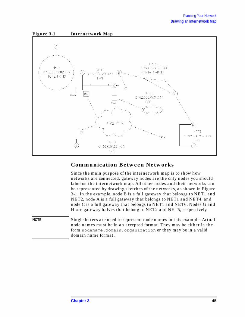
An internetwork map provides information about the wholeinternetwork. Figure 3-1 is an example of an internetwork map. Thissample internetwork will be used throughout the instructions in thischapter to help explain the other drawings and tables that make up theconfiguration worksheets.
Before you can draw your internetwork map, you must know how manynetworks your internetwork will contain, and you must know eachnetwork type (LAN, Token Ring, FDDI, 100VG-AnyLAN, 100Base-T,NS Point-to-Point, or X.25). The internetwork in the example (Figure3-1) contains six networks. NET1 and NET5 are LANs, NET2 is aPoint-to-Point network, NET3 is an X.25 network, NET4 is a TokenRing network, and NET6 is an FDDI network.
NOTE If you have an X.25 network, you should indicate the presence of eachDatacomm and Terminal Controller (DTC) in your internetwork map,as shown in this example (Figure 3-1). Both the NS 3000/iX node andthe DTC must be specially configured for X.25 links.
44 Chapter 3
Planning Your NetworkDrawing an Internetwork Map
Figure 3-1 Internetwork Map
Communication Between NetworksSince the main purpose of the internetwork map is to show hownetworks are connected, gateway nodes are the only nodes you shouldlabel on the internetwork map. All other nodes and their networks canbe represented by drawing sketches of the networks, as shown in Figure3-1. In the example, node B is a full gateway that belongs to NET1 andNET2, node A is a full gateway that belongs to NET1 and NET4, andnode C is a full gateway that belongs to NET1 and NET6. Nodes G andH are gateway halves that belong to NET2 and NET5, respectively.
NOTE Single letters are used to represent node names in this example. Actualnode names must be in an accepted format. They may be either in theform nodename.domain.organization or they may be in a validdomain name format.
Chapter 3 45
Planning Your NetworkDrawing an Internetwork Map
Network BoundariesOnce you have drawn your gateway nodes or routers, you haveestablished network boundaries. Consider the example and look atFigure 3-1. Since node B in the example is a full gateway and belongs toboth NET1 and NET2, the boundary between these two networks is atnode B itself. The boundary between NET2 and NET5 is along thegateway-half link that connects gateway nodes G and H.
IP Network AddressesEach network in your internetwork must have a unique IP networkaddress. Add these IP addresses to your internetwork map.
In the example, assume that the Class C IP network addresses arethose shown in Figure 3-1. The specific IP node addresses do not need tobe shown until completion of specific parts of the network worksheets,so node portions of IP addresses will be represented with XXX in somemaps and tables.
46 Chapter 3
Planning Your NetworkCompleting the Internetwork Table
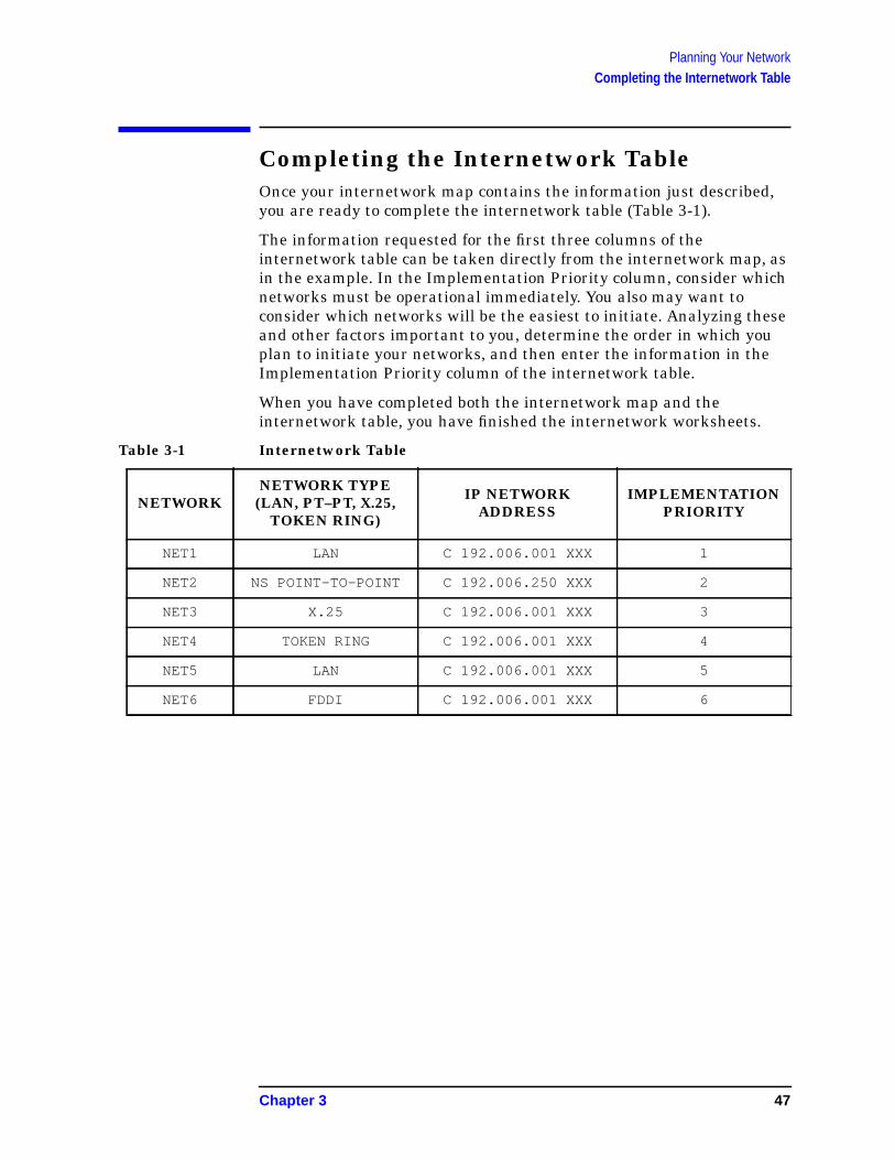
Completing the Internetwork TableOnce your internetwork map contains the information just described,you are ready to complete the internetwork table (Table 3-1).
The information requested for the first three columns of theinternetwork table can be taken directly from the internetwork map, asin the example. In the Implementation Priority column, consider whichnetworks must be operational immediately. You also may want toconsider which networks will be the easiest to initiate. Analyzing theseand other factors important to you, determine the order in which youplan to initiate your networks, and then enter the information in theImplementation Priority column of the internetwork table.
When you have completed both the internetwork map and theinternetwork table, you have finished the internetwork worksheets.
Table 3-1 Internetwork Table
NETWORKNETWORK TYPE
(LAN, PT–PT, X.25,TOKEN RING)
IP NETWORKADDRESS
IMPLEMENTATIONPRIORITY
NET1 LAN C 192.006.001 XXX 1
NET2 NS POINT-TO-POINT C 192.006.250 XXX 2
NET3 X.25 C 192.006.001 XXX 3
NET4 TOKEN RING C 192.006.001 XXX 4
NET5 LAN C 192.006.001 XXX 5
NET6 FDDI C 192.006.001 XXX 6
Chapter 3 47
Planning Your NetworkDrawing a Network Map
Drawing a Network MapA network map provides information about the configuration of thecomputers on the network and their access to remote computers. Anetwork map can be invaluable when troubleshooting.
Whenever you install a new system on your network, be sure you alsoupdate your network map. If you have not previously created a networkmap, create one now and keep it updated whenever you add or deletecomputers or interface cards or make cable changes.
In addition to maintaining a network map, you should also recordrelated system information on one of the network map worksheets,provided later in this chapter. You can use the network map worksheetas a guide for configuration and later as a record of your configurationfor both you and your HP support staff.
48 Chapter 3
Planning Your NetworkNetwork Worksheets
Network WorksheetsFor each network in your internetwork, you are asked to draw a map ofthe network and to complete two tables. One table lists node-specificinformation, and one table lists network routing information.
You also are asked to complete worksheets for each gateway half pair inyour internetwork. The worksheets for a gateway half pair consist of amap of the gateway half nodes and their connecting link and a tablecontaining information about the gateway half network interfaces.
In the sample internetwork shown in Figure 3-1, six sets of networkworksheets need to be completed: one set for each of the six networksand one set for the gateway half pair.
Take the following steps when filling out a set of network worksheets:
1. Draw your map, showing all nodes and node names. (ForPoint-to-Point networks, also show all Point-to-Point links and linknames. For a gateway-half pair, include the link name.)
2. Complete the tables: two for each network, one for each gateway-halfpair.
LAN Network WorksheetsOne set of LAN network worksheets should be used for each LAN inyour internetwork. The LAN network worksheets consist of a map ofthe LAN and two tables. One table contains information about eachnode on the LAN and one table contains network-specific internetrouting information.
In this example, we have shown the network map and worksheet forNET1, one of the LAN networks shown in Figure 3-1. Use thediscussion of the sample LAN network worksheets as a guide for fillingout your own LAN network worksheets.
LAN Network MapFigure 3-2 is a drawing of the network map for NET1. The network mapis a detailed drawing of the same network shown in the internetworkmap (Figure 3-1). The network name, the IP network address, and thenetwork type are listed at the top of the network map.
In the example, the internetwork map shows that node B is a gatewaynode. It is noted on the NET1 network map and shows the network thatthe gateway node can reach. Node B is also a proxy server. Theremaining NET1 nodes and their names are added to the network map.
Chapter 3 49
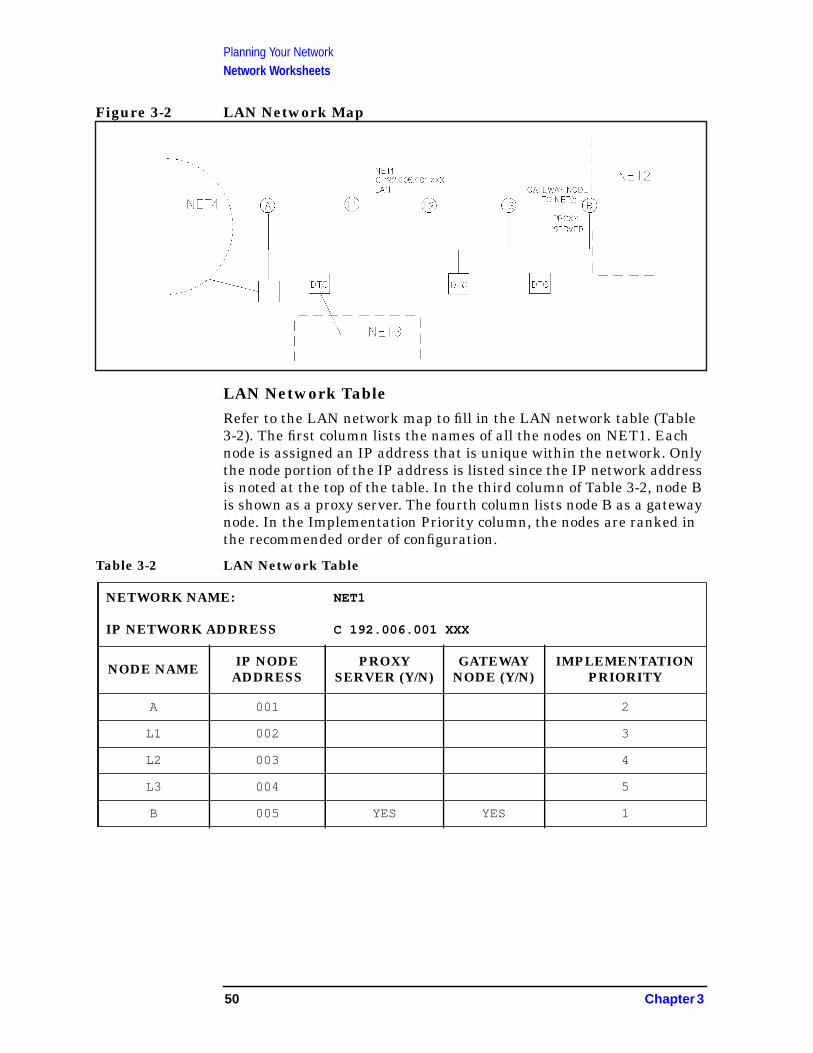
Planning Your NetworkNetwork Worksheets
Figure 3-2 LAN Network Map
LAN Network TableRefer to the LAN network map to fill in the LAN network table (Table3-2). The first column lists the names of all the nodes on NET1. Eachnode is assigned an IP address that is unique within the network. Onlythe node portion of the IP address is listed since the IP network addressis noted at the top of the table. In the third column of Table 3-2, node Bis shown as a proxy server. The fourth column lists node B as a gatewaynode. In the Implementation Priority column, the nodes are ranked inthe recommended order of configuration.
Table 3-2 LAN Network Table
NETWORK NAME: NET1
IP NETWORK ADDRESS C 192.006.001 XXX
NODE NAME IP NODEADDRESS
PROXYSERVER (Y/N)
GATEWAYNODE (Y/N)
IMPLEMENTATIONPRIORITY
A 001 2
L1 002 3
L2 003 4
L3 004 5
B 005 YES YES 1
50 Chapter 3
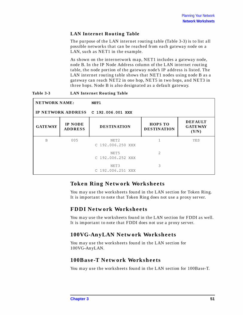
Planning Your NetworkNetwork Worksheets
LAN Internet Routing TableThe purpose of the LAN internet routing table (Table 3-3) is to list allpossible networks that can be reached from each gateway node on aLAN, such as NET1 in the example.
As shown on the internetwork map, NET1 includes a gateway node,node B. In the IP Node Address column of the LAN internet routingtable, the node portion of the gateway node’s IP address is listed. TheLAN internet routing table shows that NET1 nodes using node B as agateway can reach NET2 in one hop, NET5 in two hops, and NET3 inthree hops. Node B is also designated as a default gateway.
Table 3-3 LAN Internet Routing Table
Token Ring Network WorksheetsYou may use the worksheets found in the LAN section for Token Ring.It is important to note that Token Ring does not use a proxy server.
FDDI Network WorksheetsYou may use the worksheets found in the LAN section for FDDI as well.It is important to note that FDDI does not use a proxy server.
100VG-AnyLAN Network WorksheetsYou may use the worksheets found in the LAN section for100VG-AnyLAN.
100Base-T Network WorksheetsYou may use the worksheets found in the LAN section for 100Base-T.
NETWORK NAME: NET1
IP NETWORK ADDRESS C 192.006.001 XXX
GATEWAY IP NODEADDRESS DESTINATION HOPS TO
DESTINATION
DEFAULTGATEWAY
(Y/N)
B 005 NET2C 192.006.250 XXX
1 YES
NET5C 192.006.252 XXX
2
NET3C 192.006.251 XXX
3
Chapter 3 51
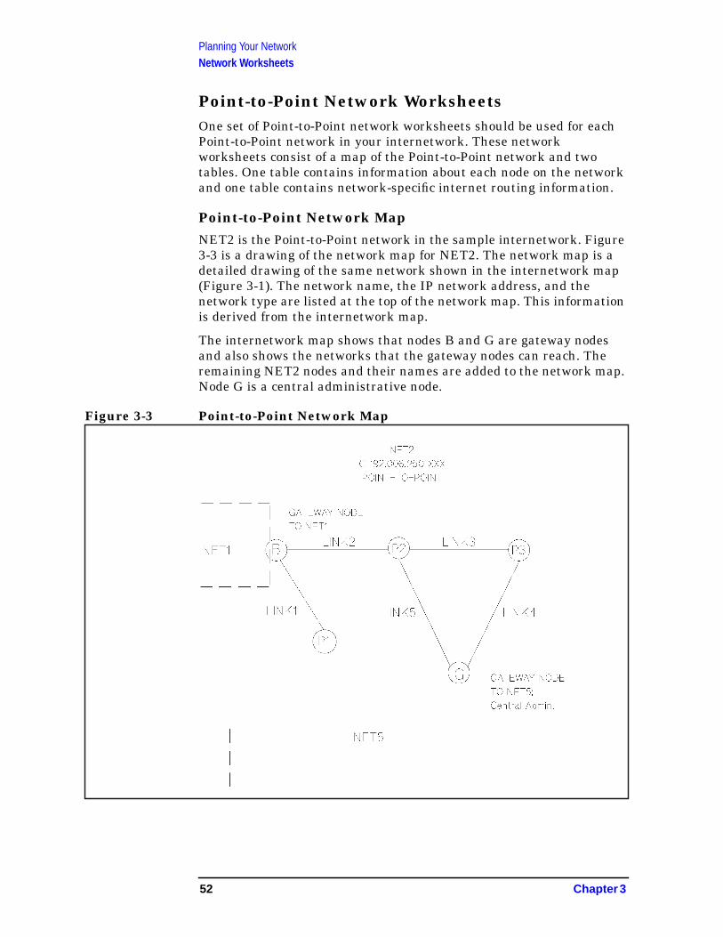
Planning Your NetworkNetwork Worksheets
Point-to-Point Network WorksheetsOne set of Point-to-Point network worksheets should be used for eachPoint-to-Point network in your internetwork. These networkworksheets consist of a map of the Point-to-Point network and twotables. One table contains information about each node on the networkand one table contains network-specific internet routing information.
Point-to-Point Network MapNET2 is the Point-to-Point network in the sample internetwork. Figure3-3 is a drawing of the network map for NET2. The network map is adetailed drawing of the same network shown in the internetwork map(Figure 3-1). The network name, the IP network address, and thenetwork type are listed at the top of the network map. This informationis derived from the internetwork map.
The internetwork map shows that nodes B and G are gateway nodesand also shows the networks that the gateway nodes can reach. Theremaining NET2 nodes and their names are added to the network map.Node G is a central administrative node.
Figure 3-3 Point-to-Point Network Map
52 Chapter 3
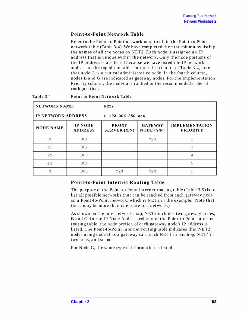
Planning Your NetworkNetwork Worksheets
Point-to-Point Network TableRefer to the Point-to-Point network map to fill in the Point-to-Pointnetwork table (Table 3-4). We have completed the first column by listingthe names of all the nodes on NET2. Each node is assigned an IPaddress that is unique within the network. Only the node portions ofthe IP addresses are listed because we have listed the IP networkaddress at the top of the table. In the third column of Table 3-4, notethat node G is a central administrative node. In the fourth column,nodes B and G are indicated as gateway nodes. For the ImplementationPriority column, the nodes are ranked in the recommended order ofconfiguration.
Table 3-4 Point-to-Point Network Table
Point-to-Point Internet Routing TableThe purpose of the Point-to-Point internet routing table (Table 3-5) is tolist all possible networks that can be reached from each gateway nodeon a Point-to-Point network, which is NET2 in the example. (Note thatthere may be more than one route to a network.)
As shown on the internetwork map, NET2 includes two gateway nodes,B and G. In the IP Node Address column of the Point-to-Point internetrouting table, the node portion of each gateway node’s IP address islisted. The Point-to-Point internet routing table indicates that NET2nodes using node B as a gateway can reach NET1 in one hop, NET4 intwo hops, and so on.
For Node G, the same type of information is listed.
NETWORK NAME: NET2
IP NETWORK ADDRESS C 192.006.250 XXX
NODE NAME IP NODEADDRESS
PROXYSERVER (Y/N)
GATEWAYNODE (Y/N)
IMPLEMENTATIONPRIORITY
B 001 YES 2
P1 002 3
P2 003 4
P3 004 5
G 005 YES YES 1
Chapter 3 53

Planning Your NetworkNetwork Worksheets
Table 3-5 Point-to-Point Internet Routing Table
NETWORK NAME: NET2
IP NETWORK ADDRESS C 192.006.250 XXX
GATEWAY IP NODEADDRESS DESTINATION HOPS TO
DESTINATION
B 001 NET1C 192.006.001 XXX
1
NET4C 192.006.002 XXX
2
NET3C 192.006.251 XXX
2
NET5C 192.006.252 XXX
3
NET6C 192.006.003 XXX
2
G 005 NET5C 192.006.252 XXX
1
NET3C 192.006.251 XXX
2
NET1C 192.006.001 XXX
3
NET4C 192.006.002 XXX
4
NET3C 192.006.003 XXX
4
54 Chapter 3

Planning Your NetworkNetwork Worksheets
X.25 Network WorksheetsOne set of X.25 network worksheets should be used for each X.25network in your internetwork. The X.25 worksheets consist of a map ofthe X.25 network and two tables. One table contains information abouteach node on the X.25 network. The other table containsnetwork-specific internet routing information.
X.25 Network MapFigure 3-4 is a drawing of the network map for NET3. The network mapis a detailed drawing of the same network shown in the internetworkmap (Figure 3-1). The network name, the IP address, and the networktype are shown on the network map. This information is derived fromthe internetwork map.
In the example, node B of NET1 and nodes H and I of NET5 are alsopart of the X.25 network. The remaining NET3 nodes and their namesare added to the network map. The network map also shows node H asa central administrative node.
Figure 3-4 X.25 Network Map
Chapter 3 55

Planning Your NetworkNetwork Worksheets
X.25 Network TableRefer to the X.25 network map to fill in the X.25 network table asshown in Table 3-6. We complete the first column by listing the namesof all the nodes on NET3. Each node is assigned an IP address that isunique within the network. Only the node portions of the IP addressesare listed since the IP network address is listed at the top of the table.In the third column of the table, node H is indicated as a centraladministrative node. The X.25 (subnet) address for each node is listedin the fifth column of the network table. The X.25 address is a decimalnumber (up to 15 digits) identifying a node’s location on the X.25 subnetfor connections using switched virtual circuits (SVCs). Usually thisaddress is inserted in CALL packets to set up connections using SVCs.If the network you will access is a public packet switching network(PSN), these addresses (where appropriate) are recorded on thenetwork subscription form.
Table 3-6 X.25 Network Table
X.25 Internet Routing TableThe purpose of the X.25 internet routing table (Table 3-7) is to list theother networks in the internetwork that can be reached from the X.25network, which is NET3 in the example. (Note that there may be morethan one route to a network.)
As shown in the internetwork map (Figure 3-4), NET3 includes twogateway nodes, B and H. In the X.25 internet routing table note thatNET3 nodes using Node H can reach NET5 in one hop, NET2 in twohops, and so on. In the IP Node Address column, the node portion of thenode’s IP address is listed.
NETWORK NAME: NET3
IP NETWORK ADDRESS C 192.006.251 XXX
NODE NAME IP NODE ADDRESS CENTRAL ADMIN NODE(Y/N) X.25 ADDRESS
H 001 Y 1234
I 002 5678
J 003 6879
B 004 9876
56 Chapter 3
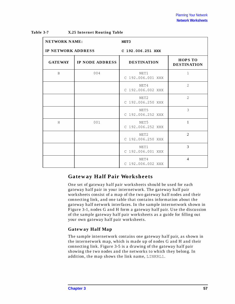
Planning Your NetworkNetwork Worksheets
Table 3-7 X.25 Internet Routing Table
Gateway Half Pair WorksheetsOne set of gateway half pair worksheets should be used for eachgateway half pair in your internetwork. The gateway half pairworksheets consist of a map of the two gateway half nodes and theirconnecting link, and one table that contains information about thegateway half network interfaces. In the sample internetwork shown inFigure 3-1, nodes G and H form a gateway half pair. Use the discussionof the sample gateway half pair worksheets as a guide for filling outyour own gateway half pair worksheets.
Gateway Half MapThe sample internetwork contains one gateway half pair, as shown inthe internetwork map, which is made up of nodes G and H and theirconnecting link. Figure 3-5 is a drawing of the gateway half pairshowing the two nodes and the networks to which they belong. Inaddition, the map shows the link name, LINKRL1 .
NETWORK NAME: NET3
IP NETWORK ADDRESS C 192.006.251 XXX
GATEWAY IP NODE ADDRESS DESTINATION HOPS TODESTINATION
B 004 NET1C 192.006.001 XXX
1
NET4C 192.006.002 XXX
2
NET2C 192.006.250 XXX
2
NET5C 192.006.252 XXX
3
H 001 NET5C 192.006.252 XXX
1
NET2C 192.006.250 XXX
2
NET1C 192.006.001 XXX
3
NET4C 192.006.002 XXX
4
Chapter 3 57

Planning Your NetworkNetwork Worksheets
Figure 3-5 Gateway-Half Map
Gateway Half Network Interface TableTable 3-8 is based on the map discussed in the previous section. Bothgateway half nodes, the full IP addresses of the partner nodes, theconnected networks, and the name of the link are listed. Usually, thelink name will be the same from the perspective of each gateway half.The address of the partner gateway half is shown to demonstrate thatthe partner’s address is entered during configuration of a gateway halfnetwork interface.
Table 3-8 Gateway Half Network Interface Table
NETWORK NAMES: NET2, NET3
GATEWAYHALF NODE
FULL IP ADDRESSOF PARTNER
CONNECTEDNETWORK LINK NAME
G/NET2 C 192.006.251 005 NET5 LINKRL1
H/NET5 C 192.006.252 001 NET2 LINKRL1
58 Chapter 3

Planning Your NetworkNetwork Directory Worksheet
Network Directory WorksheetYou can complete the network directory information table shown belowfor each network directory you are configuring. For your node and foreach destination node, you must make a full entry in the networkdirectory. The entry includes the destination node’s name and IPaddress, its NI type, the global/local setting, and any additional addressthat is required based on the NI type. See Chapter 11, “Configuring theNetwork Directory,” for more information on NI types and additionaladdresses. Table 3-9 shows some of the network directory entries youmight configure for node B of the internetwork shown in Figure 3-1.
Table 3-9 Network Directory Information Table
NODENAME
GLOBAL ORLOCAL IP ADDRESS TYPE ADDITIONAL
ADDRESS
H GLOBAL C 192.006.252 001 1
I LOCAL C 192.006.252 002 1
J GLOBAL C 192.006.251 003 3 6879
A GLOBAL C 192.006.001 001 5 08-00-09-11-22-11
K GLOBAL C 192.006.002 001 1
Chapter 3 59

Planning Your NetworkNetwork Directory Worksheet
60 Chapter 3
4 Planning for Node Configuration
This chapter describes how to complete node worksheets before youstart configuration. You will need to collect some information ahead oftime to complete these tasks.
The main purpose of the node worksheets is to determine theinformation you will need to configure for each node during NMMGR’sguided configuration. This information depends on the type of networkyou have. For a description of the fields in these worksheets, seeChapter 6, “Configuring a LAN, Token Ring, FDDI, 100VG-AnyLAN,100Base-T Node,” for information on LAN, Token Ring, and FDDI, andChapter 7, “Configuring a Point-to-Point Node,” for information onPoint-to-Point and Chapter 8, “Configuring an X.25 Node,” forinformation on X.25.
It is recommended that you make copies of these worksheets and fill inthe parameter information, then use these worksheets to guide youthrough configuration in NMMGR.
Node worksheets list only the fields you can configure during guidedconfiguration, which allows you to configure your nodes as quickly aspossible. For information on configuration parameters that areavailable through non-guided configuration, see the NS 3000/iXNMMGR Screens Reference Manual.
This chapter includes:
• Node worksheet information.
• Node worksheet information.
• Token Ring configuration worksheet
• FDDI configuration worksheet.
• 100VG-AnyLAN configuration worksheet.
• 100Base-T configuration worksheet.
• Point-to-Point configuration worksheet.
• X.25 configuration worksheet.
• X.25 virtual circuit configuration worksheet.
• Neighbor gateway worksheet information.
• Neighbor gateway configuration worksheet.
• Neighbor gateway reachable networks worksheet Information.
• Neighbor gateway reachable networks configuration worksheet.
61
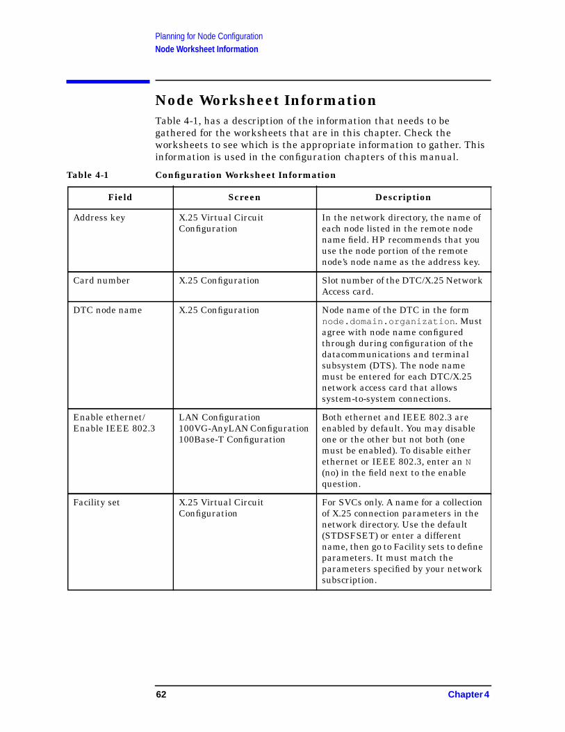
Planning for Node ConfigurationNode Worksheet Information
Node Worksheet InformationTable 4-1, has a description of the information that needs to begathered for the worksheets that are in this chapter. Check theworksheets to see which is the appropriate information to gather. Thisinformation is used in the configuration chapters of this manual.
Table 4-1 Configuration Worksheet Information
Field Screen Description
Address key X.25 Virtual CircuitConfiguration
In the network directory, the name ofeach node listed in the remote nodename field. HP recommends that youuse the node portion of the remotenode’s node name as the address key.
Card number X.25 Configuration Slot number of the DTC/X.25 NetworkAccess card.
DTC node name X.25 Configuration Node name of the DTC in the formnode.domain.organization . Mustagree with node name configuredthrough during configuration of thedatacommunications and terminalsubsystem (DTS). The node namemust be entered for each DTC/X.25network access card that allowssystem-to-system connections.
Enable ethernet/Enable IEEE 802.3
LAN Configuration100VG-AnyLAN Configuration100Base-T Configuration
Both ethernet and IEEE 802.3 areenabled by default. You may disableone or the other but not both (onemust be enabled). To disable eitherethernet or IEEE 802.3, enter an N(no) in the field next to the enablequestion.
Facility set X.25 Virtual CircuitConfiguration
For SVCs only. A name for a collectionof X.25 connection parameters in thenetwork directory. Use the default(STDSFSET) or enter a differentname, then go to Facility sets to defineparameters. It must match theparameters specified by your networksubscription.
62 Chapter 4

Planning for Node ConfigurationNode Worksheet Information
IP address LAN Configuration;Token Ring Configuration;FDDI Configuration;100VG-AnyLANConfiguration; 100Base-TConfiguration; Point-to-PointConfiguration;X.25 Configuration
There are two methods of entering aninternet protocol (IP) address withinNMMGR:
1. Enter the fully qualified IPaddress (for example, Class C,C 192.191.191 009 ).
OR
2. Enter only the network (nnn)and node (xxx) portions of theIP address as four positiveintegers between 0 and 255separated by periods or blanks(for example, 15.123.44.98 ).
You need not enter thefollowing items as NMMGRwill fill these in:
a. Class A, B, C
b. Leading zeros for thenetwork and node portion ofthe IP address.
All nodes on the same network mustuse the same class of IP address. Thenetwork portion of the address mustbe the same for all nodes on the samenetwork.
IP subnet mask LAN Configuration;Token Ring Configuration;FDDI Configuration;100VG-AnyLANConfiguration; 100Base-TConfiguration; Point-to-PointConfiguration;X.25 Configuration
The IP subnet mask is optional. An IPsubnet mask is specified in the sameformat as an IP address. The maskidentifies which bits of an IP addresswill be used to define a subnetwork.For more information refer, to theconfiguration chapter for the type oflink you are configuring.
Field Screen Description
Chapter 4 63
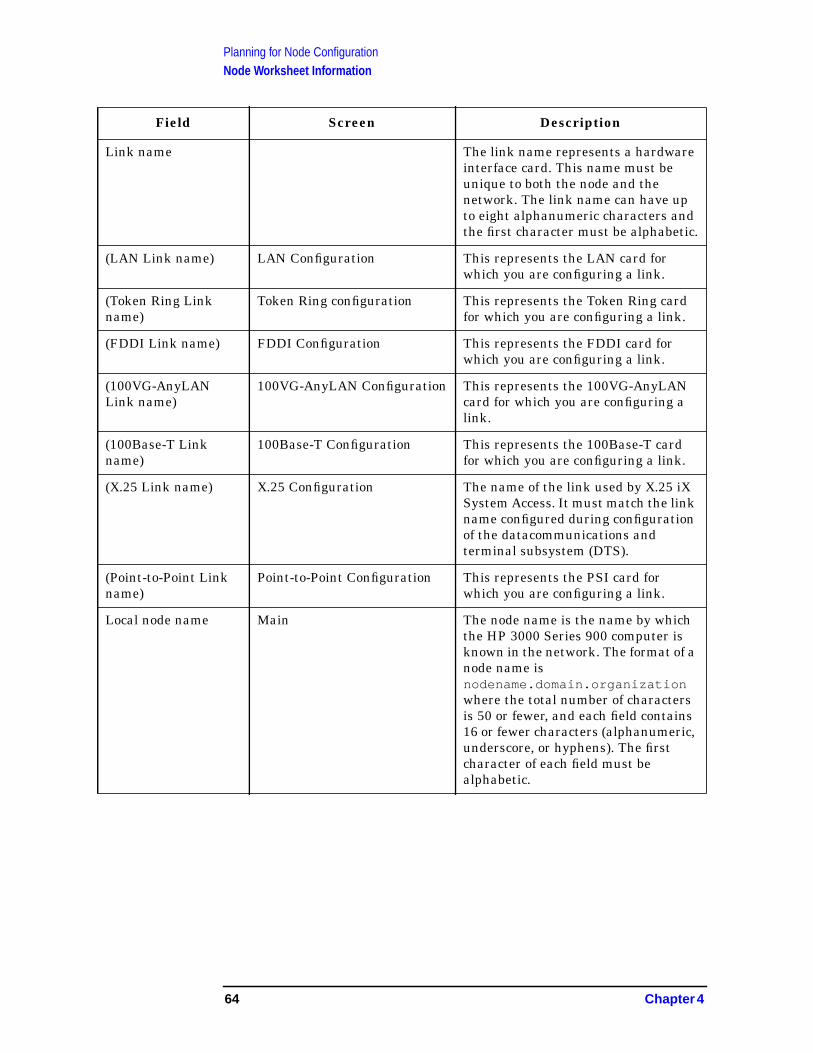
Planning for Node ConfigurationNode Worksheet Information
Link name The link name represents a hardwareinterface card. This name must beunique to both the node and thenetwork. The link name can have upto eight alphanumeric characters andthe first character must be alphabetic.
(LAN Link name) LAN Configuration This represents the LAN card forwhich you are configuring a link.
(Token Ring Linkname)
Token Ring configuration This represents the Token Ring cardfor which you are configuring a link.
(FDDI Link name) FDDI Configuration This represents the FDDI card forwhich you are configuring a link.
(100VG-AnyLANLink name)
100VG-AnyLAN Configuration This represents the 100VG-AnyLANcard for which you are configuring alink.
(100Base-T Linkname)
100Base-T Configuration This represents the 100Base-T cardfor which you are configuring a link.
(X.25 Link name) X.25 Configuration The name of the link used by X.25 iXSystem Access. It must match the linkname configured during configurationof the datacommunications andterminal subsystem (DTS).
(Point-to-Point Linkname)
Point-to-Point Configuration This represents the PSI card forwhich you are configuring a link.
Local node name Main The node name is the name by whichthe HP 3000 Series 900 computer isknown in the network. The format of anode name isnodename.domain.organizationwhere the total number of charactersis 50 or fewer, and each field contains16 or fewer characters (alphanumeric,underscore, or hyphens). The firstcharacter of each field must bealphabetic.
Field Screen Description
64 Chapter 4

Planning for Node ConfigurationNode Worksheet Information
Local domain name NS Configuration The name of the system in ARPANETstandard format. It is composed oflabels, with each label separated by aperiod. Labels must start with a letteror digit and have as interiorcharacters only letters, digits,hyphens(-), or underbars (_). Theremay be any number of labels, but thetotal length of the name, includingperiods, is limited to 255 characters.(If not using domain names fornetwork access, leave the local nodename in this field.)
Network directoryname
X.25 Virtual CircuitConfiguration
The network directory name must beconfigured for each new node. Thenetwork directory containsinformation that one node needs inorder to communicate with othernodes. The only network directoryname supported by HP isNSDIR.NET.SYS .
Network Interface(NI) name
LAN Configuration;Token Ring Configuration;FDDI Configuration;100VG-AnyLANConfiguration; 100Base-TConfiguration; Point-to-PointConfiguration;X.25 Configuration
The network interface (NI) name isused to easily identify a networkinterface. The name can be up to eightalphanumeric characters, startingwith a letter. The maximum numberof NIs that can be configured on anode is 12. If a node interfaces to morethan one network, give each NI onthat node a unique name. You will usethe NI name with the NETCONTROLcommand to start the transport andnetwork link.
Permanent VCnumber
X.25 Virtual circuitConfiguration
For PVCs only. In the networkdirectory, the number of thepermanent virtual circuit on theremote node.
Physical path Point-to-Point Configuration This is the location of theprogrammable serial interface. Referto the system documentation for yourHP 3000 model to find the physicalpath of the programmable serialinterface (PSI) card.
Field Screen Description
Chapter 4 65
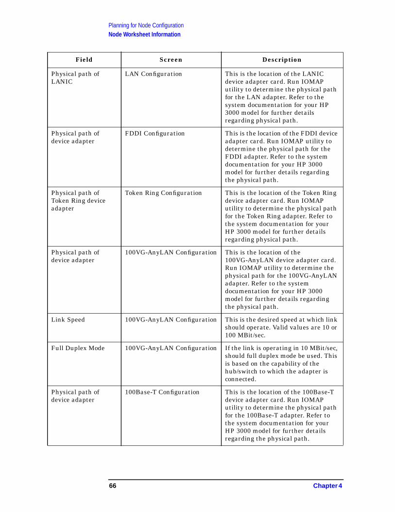
Planning for Node ConfigurationNode Worksheet Information
Physical path ofLANIC
LAN Configuration This is the location of the LANICdevice adapter card. Run IOMAPutility to determine the physical pathfor the LAN adapter. Refer to thesystem documentation for your HP3000 model for further detailsregarding physical path.
Physical path ofdevice adapter
FDDI Configuration This is the location of the FDDI deviceadapter card. Run IOMAP utility todetermine the physical path for theFDDI adapter. Refer to the systemdocumentation for your HP 3000model for further details regardingthe physical path.
Physical path ofToken Ring deviceadapter
Token Ring Configuration This is the location of the Token Ringdevice adapter card. Run IOMAPutility to determine the physical pathfor the Token Ring adapter. Refer tothe system documentation for yourHP 3000 model for further detailsregarding physical path.
Physical path ofdevice adapter
100VG-AnyLAN Configuration This is the location of the100VG-AnyLAN device adapter card.Run IOMAP utility to determine thephysical path for the 100VG-AnyLANadapter. Refer to the systemdocumentation for your HP 3000model for further details regardingthe physical path.
Link Speed 100VG-AnyLAN Configuration This is the desired speed at which linkshould operate. Valid values are 10 or100 MBit/sec.
Full Duplex Mode 100VG-AnyLAN Configuration If the link is operating in 10 MBit/sec,should full duplex mode be used. Thisis based on the capability of thehub/switch to which the adapter isconnected.
Physical path ofdevice adapter
100Base-T Configuration This is the location of the 100Base-Tdevice adapter card. Run IOMAPutility to determine the physical pathfor the 100Base-T adapter. Refer tothe system documentation for yourHP 3000 model for further detailsregarding the physical path.
Field Screen Description
66 Chapter 4

Planning for Node ConfigurationNode Worksheet Information
Use Auto-Negotiation 100Base-T Configuration Should the adapter attempt toauto-negotiate with the hub/switch.Use this feature ONLY if thehub/switch supports this feature also.
Link Speed 100Base-T Configuration This is the desired speed at which linkshould operate. Valid values are 10 or100 MBit/sec. This field is only neededif auto-negotiation is not used.
Full Duplex Mode 100Base-T Configuration Should full duplex mode be used. Thisis based on the capability of thehub/switch to which the adapter isconnected. This field is only needed ifauto-negotiation is not used.
Proxy node LAN Configuration The proxy field is optional. Enter Y(yes) only if your network hasinternetworks (networks withgateways) or non-HP nodes.Establishing a proxy node is a way ofplacing node name and addressmapping information in a singlelocation. For more information, seethe configuration chapter for LANlink.
Remote IP address X.25 Virtual CircuitConfiguration
In the network directory, the IPaddress of each node listed in theremote node name field.
Remote node name X.25 Virtual CircuitConfiguration
In the network directory, the name ofeach remote X.25 node on the network
Remote X.25 address X.25 Virtual CircuitConfiguration
For SVCs only. In the networkdirectory, the X.25 address of theremote host for X.25 public datanetworks or private networks.
Field Screen Description
Chapter 4 67

Planning for Node ConfigurationNode Worksheet Information
Security class X.25 Virtual CircuitConfiguration
For SVCs only. In the networkdirectory, the security to be applied forconnection establishment with theremote node.
Speed Point-to-Point Configuration The line transmission speed is givenin bits per second. For direct connectthe value must be supported by thecable. Values are 1200, 2400, 4800,9600, 19200, 38400, 56000, and64000. The default is 56000.
Type Point-to-Point Configuration Enter DD (direct dial) if you alwayswant to call the same host over a diallink. If you choose DD the remote hostdoes not have to be adjacent and othernodes can be accessed through theremote host. Enter SD if you want tocall more than one adjacent remotenode over a dial link withoutreconfiguring. If you choose SD, noother remote nodes can be accessedthrough the remote host; it is an endpoint in the connection. Enter DC ifthe link is a leased line, private line,or other non-switched link.
Field Screen Description
68 Chapter 4
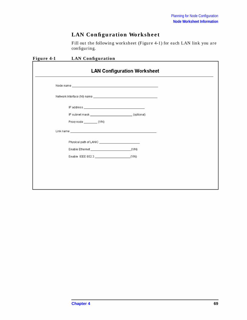
Planning for Node ConfigurationNode Worksheet Information
LAN Configuration WorksheetFill out the following worksheet (Figure 4-1) for each LAN link you areconfiguring.
Figure 4-1 LAN Configuration
Chapter 4 69

Planning for Node ConfigurationNode Worksheet Information
Token Ring Configuration WorksheetFill out the following worksheet (Figure 4-2) for each Token Ring linkyou are configuring.
Figure 4-2 Token Ring Configuration
70 Chapter 4
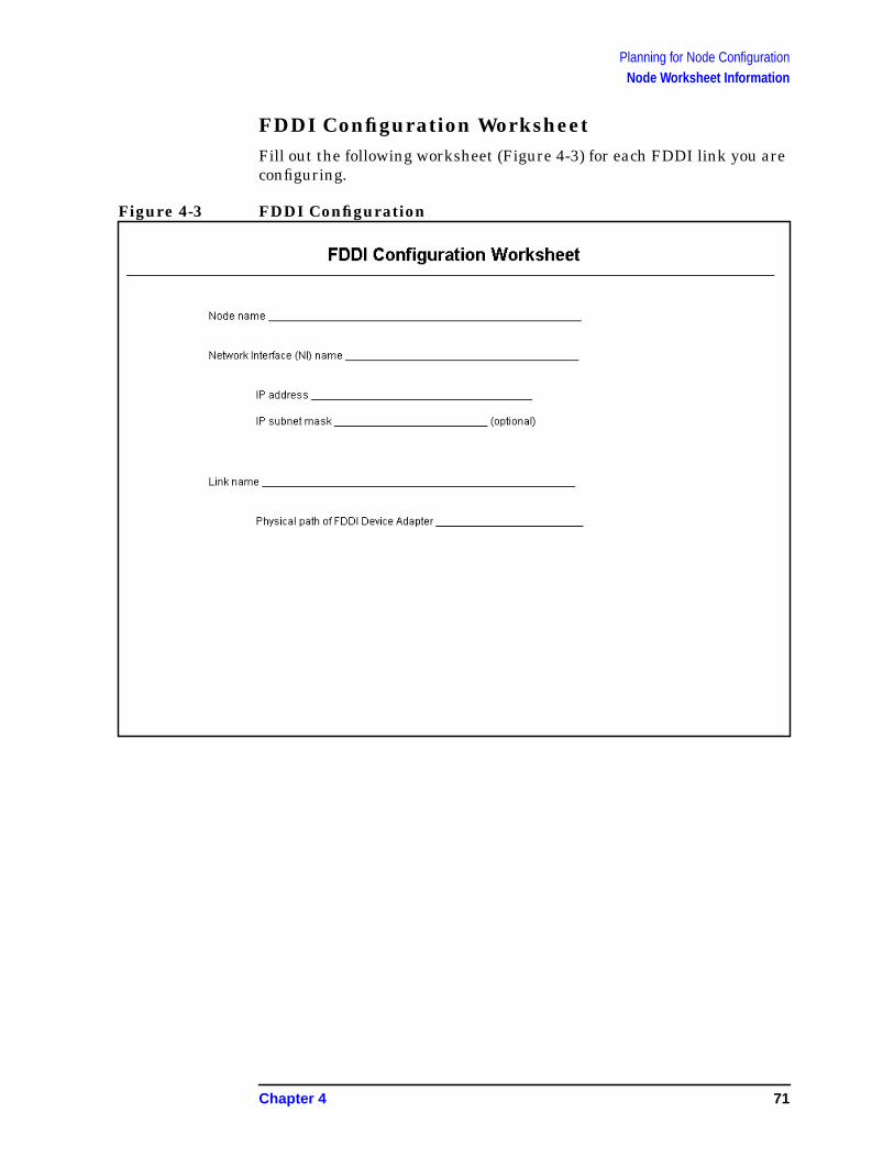
Planning for Node ConfigurationNode Worksheet Information
FDDI Configuration WorksheetFill out the following worksheet (Figure 4-3) for each FDDI link you areconfiguring.
Figure 4-3 FDDI Configuration
Chapter 4 71

Planning for Node ConfigurationNode Worksheet Information
100VG-AnyLAN Configuration WorksheetFill out the following worksheet (Figure 4-4) for each 100VG-AnyLANlink you are configuring.
Figure 4-4 100VG-AnyLAN Configuration
72 Chapter 4
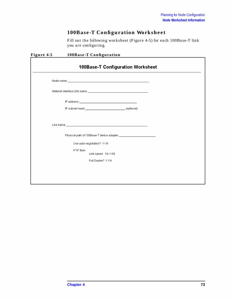
Planning for Node ConfigurationNode Worksheet Information
100Base-T Configuration WorksheetFill out the following worksheet (Figure 4-5) for each 100Base-T linkyou are configuring.
Figure 4-5 100Base-T Configuration
Chapter 4 73

Planning for Node ConfigurationNode Worksheet Information
Point-to-Point Configuration WorksheetFill out the following worksheet (Figure 4-6) for each Point-to-Point linkyou are configuring.
Figure 4-6 Point-to-Point Configuration
74 Chapter 4
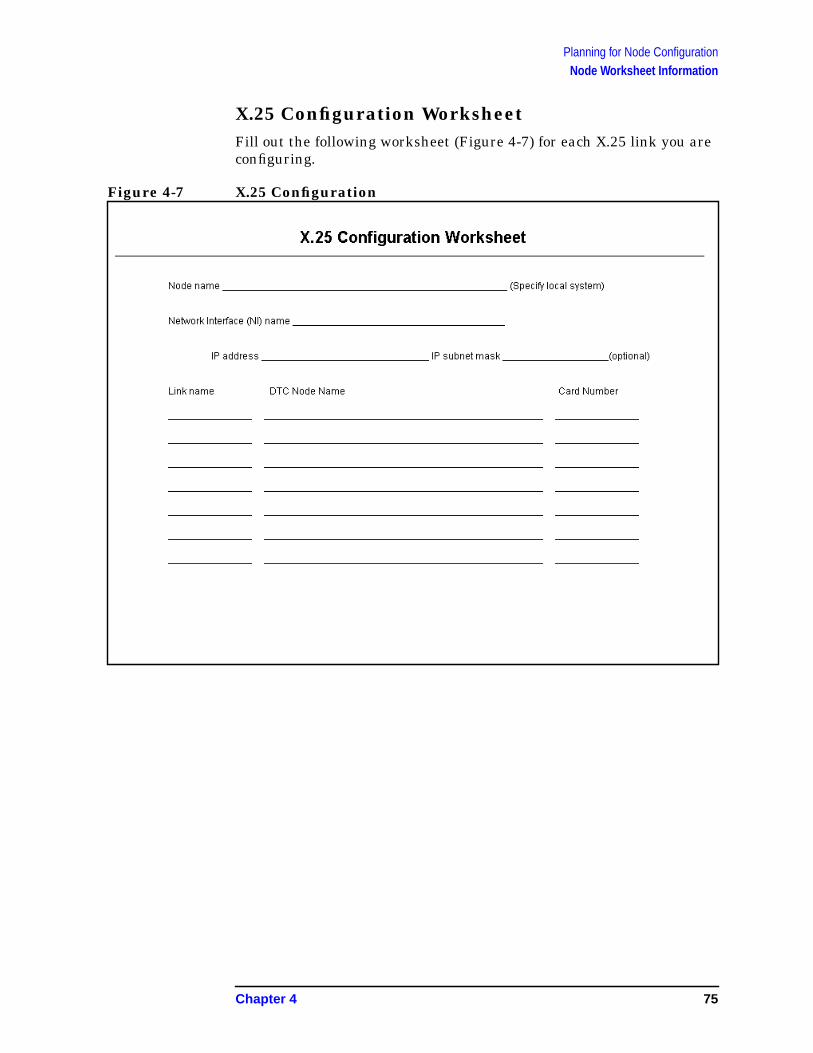
Planning for Node ConfigurationNode Worksheet Information
X.25 Configuration WorksheetFill out the following worksheet (Figure 4-7) for each X.25 link you areconfiguring.
Figure 4-7 X.25 Configuration
Chapter 4 75
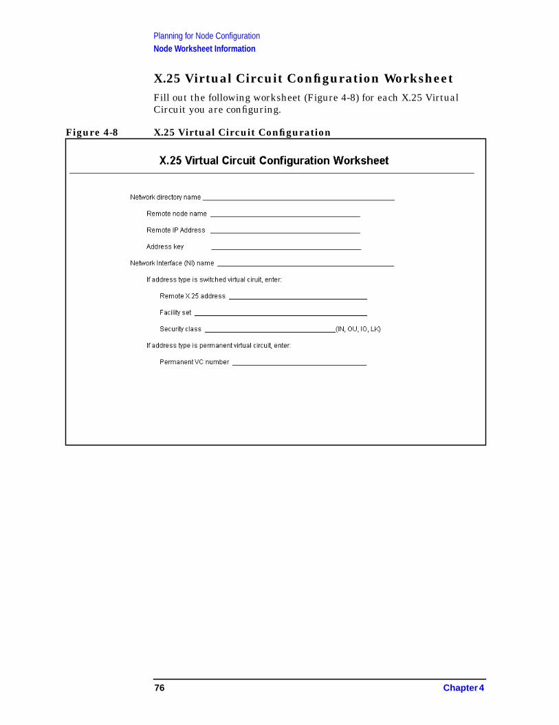
Planning for Node ConfigurationNode Worksheet Information
X.25 Virtual Circuit Configuration WorksheetFill out the following worksheet (Figure 4-8) for each X.25 VirtualCircuit you are configuring.
Figure 4-8 X.25 Virtual Circuit Configuration
76 Chapter 4
Planning for Node ConfigurationNeighbor Gateway Worksheet Information
Neighbor Gateway Worksheet InformationThe following is a description of the information that needs to begathered for the worksheets that follow in this chapter. Thisinformation is used for configuring nodes.
Gateway name Enter the name of a gateway that is on the samenetwork as the node that you are configuring. (Nodesare on the same network if the network portions oftheir IP addresses are the same.) Each gateway namecan be as long as eight alphanumeric characters. Thefirst character must be alphabetic
New name Enter the name of a gateway that is on the samenetwork as the node that you are configuring. (Nodesare on the same network if the network portions oftheir IP addresses are the same.) Each gateway namecan be as long as eight alphanumeric characters. Thefirst character must be alphabetic.
ConfiguredGateways This is a list of gateways that are configured. Gateway
names are automatically entered in these fields whenthey are entered above.
Chapter 4 77
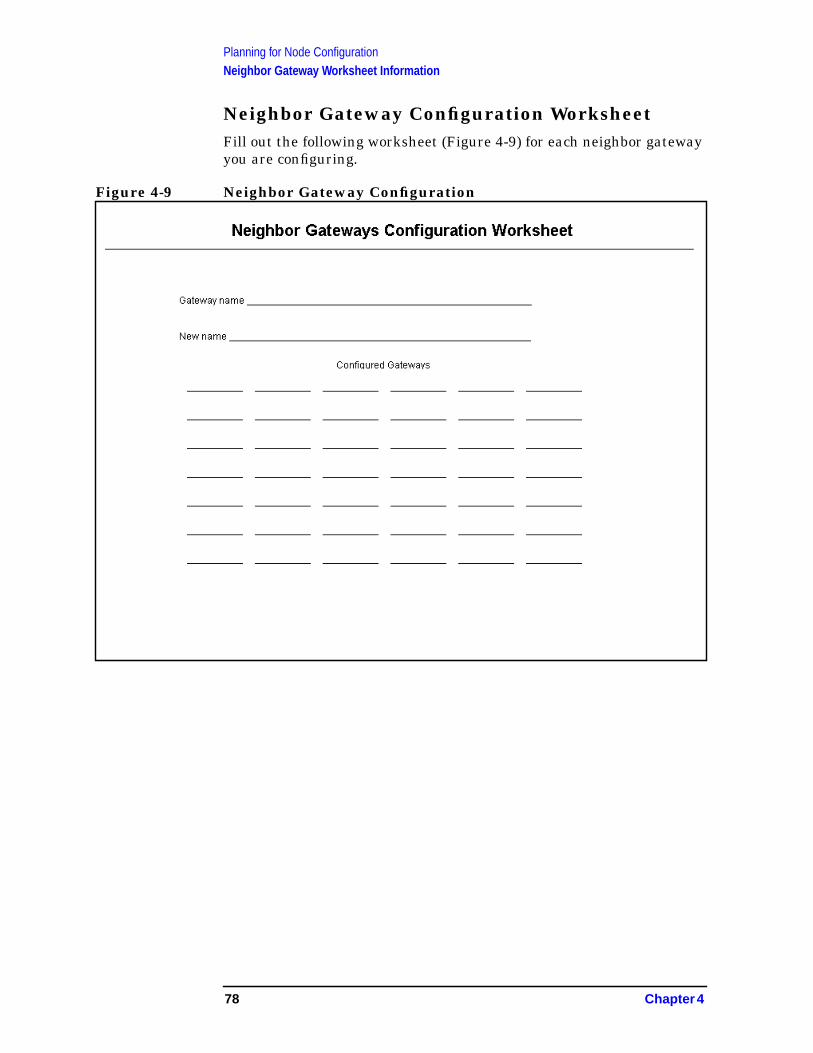
Planning for Node ConfigurationNeighbor Gateway Worksheet Information
Neighbor Gateway Configuration WorksheetFill out the following worksheet (Figure 4-9) for each neighbor gatewayyou are configuring.
Figure 4-9 Neighbor Gateway Configuration
78 Chapter 4
Planning for Node ConfigurationNeighbor Gateway Reachable networks Worksheet Information
Neighbor Gateway Reachable networksWorksheet InformationThe following is a description of the information that needs to begathered for the worksheets that follow in this chapter. Thisinformation is used for configuring nodes.
NeighborGateway IPInternetAddress This is the IP address of the gateway specified on the
Neighbor Gateways screen. The IP address is in thesame format as the LAN Configuration screen. Anexample of an address is: C 192.007.007 001
IP networkaddress The IP addresses of all the remote networks that can be
reached through the gateway whose IP address isconfigured in the previous field. If the gateway node isto serve as a default gateway, enter an at sign (@) in oneof these fields.
IP mask The IP mask allows you to specify a subnet mask foreach reachable network. This is in the same format asan IP address. This mask is optional.
Hops This is the number of hops (full gateways) that a packettravels to reach a remote network from a local network.Two partner gateway halves count as one hop.
Chapter 4 79

Planning for Node ConfigurationNeighbor Gateway Reachable networks Worksheet Information
Neighbor Gateway Reachable NetworksConfiguration WorksheetFill out the following worksheet (Figure 4-10) for each neighborgateway reachable network you are configuring.
Figure 4-10 Reachable Network Configuration
80 Chapter 4

5 Introductory Screens
The introductory screens are the first few screens that are displayedwhen you configure a node using NMMGR.
Figure 5-1 shows the screen flow of the introductory screens.[FUNCTION] denotes the function key used at a screen to invoke thenext screen on the screen flow. This chapter describes the introductoryscreens relevant to configuring NS unguided networks.
Figure 5-1 NMMGR Screen Flow
81

Introductory ScreensTo Begin the Configuration Process
To Begin the Configuration ProcessThe procedures that follow describe how to modify the NMMGRconfiguration file for the introductory screens.
To Start NMMGRNode manager (NM) or network administrator (NA) capabilities arerequired to run this program.
To run NMMGR:
1. Type NMMGR.PUB.SYS at the system prompt (: ).
2. Press [RETURN] .
NOTE As of version 4.0 of the operating system, you can modify the linkconfigurations in NMCONFIG.PUB.SYS when the Network Servicesare active. However, the network must be stopped and restarted for thechanges made in NMMGR to be implemented.
If NS is down, you will see the following two messages in response tothe NETCONTROL STATUS command:
TRANSPORT NOT ACTIVE. (NETEXPORTWARN 0001) ENCOUNTEREDONE OR MORE WARNINGS WHILE PROCESSING COMMAND.(CIWARN 4437)
To Open the Configuration FileThe Open Configuration/Directory File screen (#1) in Figure 5-2 is thefirst screen displayed when you run NMMGR.
82 Chapter 5
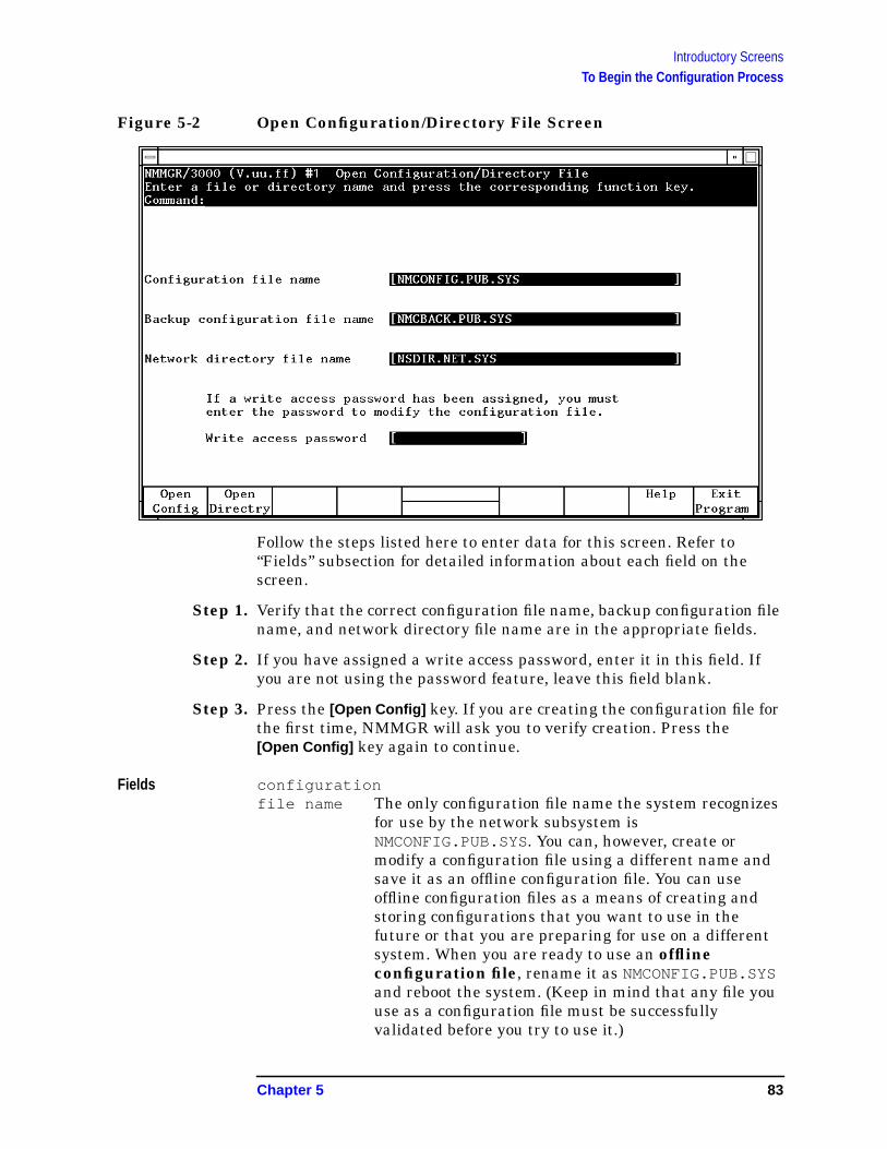
Introductory ScreensTo Begin the Configuration Process
Figure 5-2 Open Configuration/Directory File Screen
Follow the steps listed here to enter data for this screen. Refer to“Fields” subsection for detailed information about each field on thescreen.
Step 1. Verify that the correct configuration file name, backup configuration filename, and network directory file name are in the appropriate fields.
Step 2. If you have assigned a write access password, enter it in this field. Ifyou are not using the password feature, leave this field blank.
Step 3. Press the [Open Config] key. If you are creating the configuration file forthe first time, NMMGR will ask you to verify creation. Press the[Open Config] key again to continue.
Fields configurationfile name The only configuration file name the system recognizes
for use by the network subsystem isNMCONFIG.PUB.SYS. You can, however, create ormodify a configuration file using a different name andsave it as an offline configuration file. You can useoffline configuration files as a means of creating andstoring configurations that you want to use in thefuture or that you are preparing for use on a differentsystem. When you are ready to use an offlineconfiguration file, rename it as NMCONFIG.PUB.SYSand reboot the system. (Keep in mind that any file youuse as a configuration file must be successfullyvalidated before you try to use it.)
Chapter 5 83

Introductory ScreensTo Begin the Configuration Process
Backupconfigurationfile name A backup file name must be specified whenever a
configuration file is opened or created. The defaultbackup configuration file name isNMCBACK.group.account . The backup file will beautomatically updated with the contents of theconfiguration file each time the configuration file issuccessfully validated.
Networkdirectoryfile name A network directory must be configured in the following
circumstances:
• nodes running X.25
• nodes not using domain name services
• nodes on a LAN network that do not support theHP-PROBE protocol
The only network directory file name supported by HPis NSDIR.NET.SYS . This file is part of a KSAM pair. Akey file is created at the same time as this data file. Thekey file will automatically be named using the first sixletters of the network directory file name, appendedwith the character K. For example, NSDIRK.NET.SYS isthe name of the key file associated with the data fileNSDIR.NET.SYS . If the name of the data file is lessthan six letters long, then the entire file name would beappended with a K.
Write accesspassword The password is an optional feature. If a password has
been assigned, you must enter it in the password fieldto update the configuration file or the directory file. It isstill possible to open an existing file without using anassigned password, but the file will be in read onlymode and NMMGR will not accept changes.
If a password has not been assigned, you should ignorethe password field.
If you want to assign a password for the system you areconfiguring, see Using the Node Management Services(NMS) Utilities.
84 Chapter 5
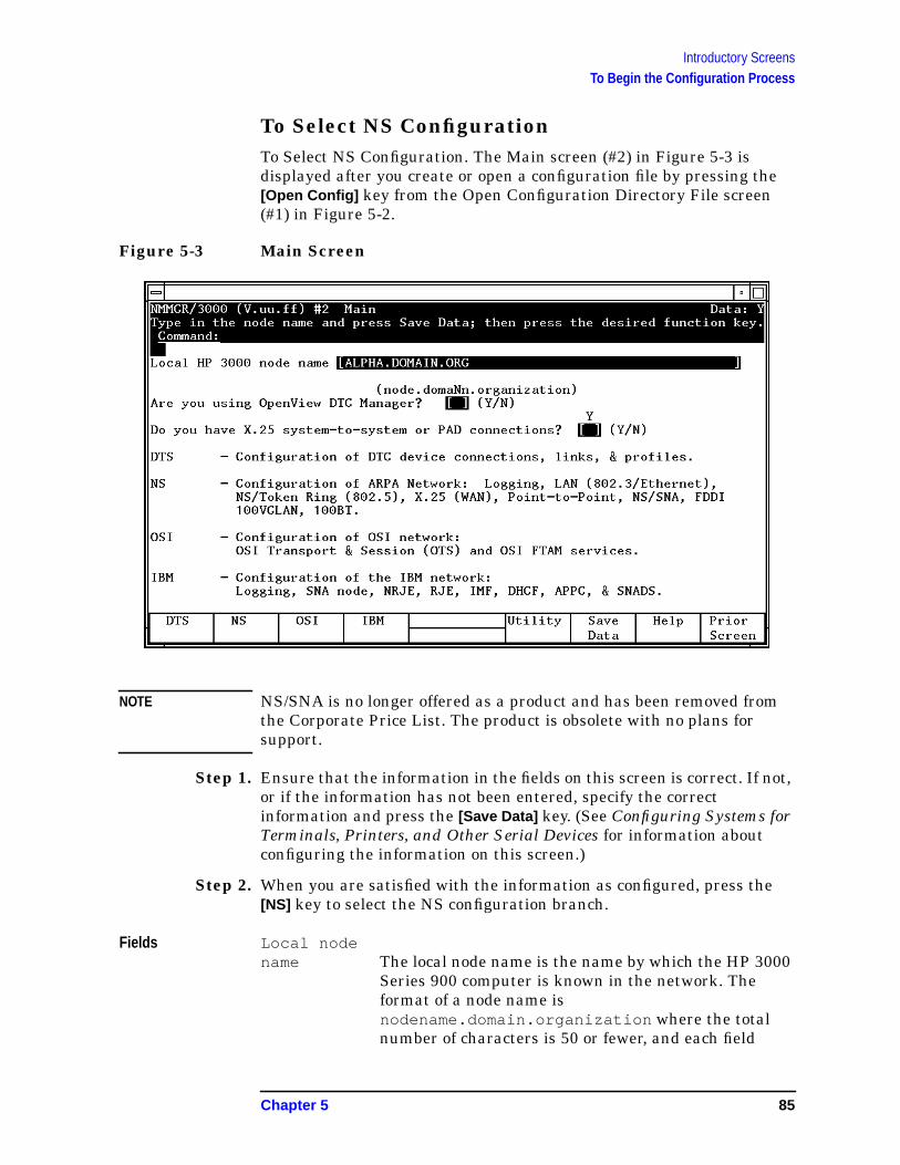
Introductory ScreensTo Begin the Configuration Process
To Select NS ConfigurationTo Select NS Configuration. The Main screen (#2) in Figure 5-3 isdisplayed after you create or open a configuration file by pressing the[Open Config] key from the Open Configuration Directory File screen(#1) in Figure 5-2.
Figure 5-3 Main Screen
NOTE NS/SNA is no longer offered as a product and has been removed fromthe Corporate Price List. The product is obsolete with no plans forsupport.
Step 1. Ensure that the information in the fields on this screen is correct. If not,or if the information has not been entered, specify the correctinformation and press the [Save Data] key. (See Configuring Systems forTerminals, Printers, and Other Serial Devices for information aboutconfiguring the information on this screen.)
Step 2. When you are satisfied with the information as configured, press the[NS] key to select the NS configuration branch.
Fields Local nodename The local node name is the name by which the HP 3000
Series 900 computer is known in the network. Theformat of a node name isnodename.domain.organization where the totalnumber of characters is 50 or fewer, and each field
Chapter 5 85
Introductory ScreensTo Begin the Configuration Process
contains 16 or fewer characters (alphanumeric,underscore, or hyphens). The first character of eachfield must be alphabetic.
The nodename portion of each node name must beunique within the node’s network. Thenodename.domain portion of each node name must beunique within the internetwork. HP recommends thatall nodes on the network be assigned the same domainand organization.
Assign meaningful node names. For example,MKTG.BND.HPand LAB.BND.HP are meaningful namesfor two nodes on the same network withinHewlett-Packard. One node (MKTG.BND.HP) is used bythe marketing department. The other node(LAB.BND.HP) is used by the lab. The domain field isthe same because the nodes belong to the samenetwork. The organization field is the same because thenodes belong to the same internetwork.
Are you usingOpenView DTCManager? If you answer yes to this question, NMMGR assumes
you are using a PC to manage your system and takesyou to the corresponding set of screens when youconfigure DTS. If you answer no, NMMGR assumes youare using host-based network management and takesyou to a different set of DTS screens. You shouldalready have answered this question when youconfigured DTS.
Do you have X.25system-to-system or PADconnections? If you answer yes to this question, NMMGR assumes
you are configuring X.25 connections and takes you tothe set of screens required to configure DTC X.25Network Access Cards when you configure DTS. If youanswer no, NMMGR assumes you have no need toconfigure X.25 connections and takes you to a differentset of DTS screens. You should already have answeredthis question when you configured DTS.
86 Chapter 5
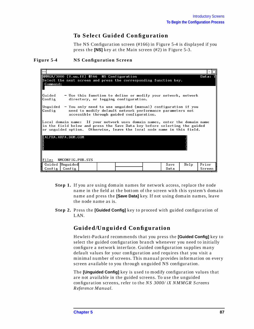
Introductory ScreensTo Begin the Configuration Process
To Select Guided ConfigurationThe NS Configuration screen (#166) in Figure 5-4 is displayed if youpress the [NS] key at the Main screen (#2) in Figure 5-3.
Figure 5-4 NS Configuration Screen
Step 1. If you are using domain names for network access, replace the nodename in the field at the bottom of the screen with this system’s domainname and press the [Save Data] key. If not using domain names, leavethe node name as is.
Step 2. Press the [Guided Config] key to proceed with guided configuration ofLAN.
Guided/Unguided ConfigurationHewlett-Packard recommends that you press the [Guided Config] key toselect the guided configuration branch whenever you need to initiallyconfigure a network interface. Guided configuration supplies manydefault values for your configuration and requires that you visit aminimal number of screens. This manual provides information on everyscreen available to you through unguided NS configuration.
The [Unguided Config] key is used to modify configuration values thatare not available in the guided screens. To use the unguidedconfiguration screens, refer to the NS 3000/iX NMMGR ScreensReference Manual.
Chapter 5 87
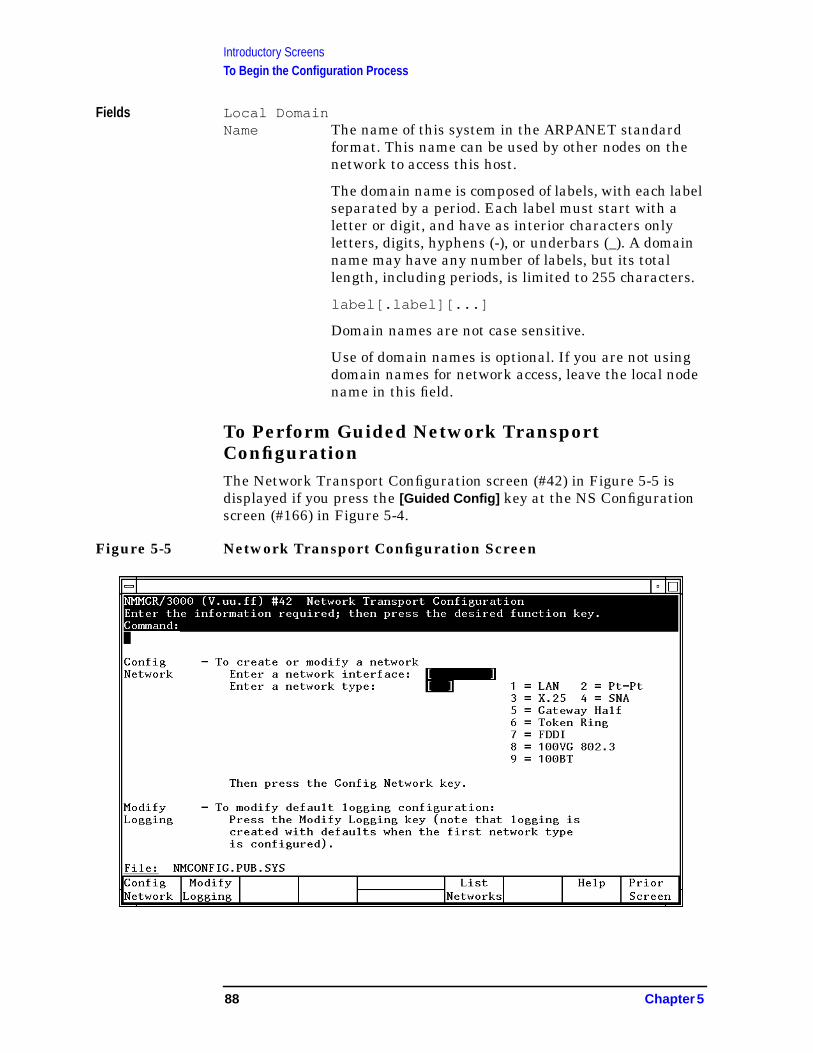
Introductory ScreensTo Begin the Configuration Process
Fields Local DomainName The name of this system in the ARPANET standard
format. This name can be used by other nodes on thenetwork to access this host.
The domain name is composed of labels, with each labelseparated by a period. Each label must start with aletter or digit, and have as interior characters onlyletters, digits, hyphens (-), or underbars (_). A domainname may have any number of labels, but its totallength, including periods, is limited to 255 characters.
label[.label][...]
Domain names are not case sensitive.
Use of domain names is optional. If you are not usingdomain names for network access, leave the local nodename in this field.
To Perform Guided Network TransportConfigurationThe Network Transport Configuration screen (#42) in Figure 5-5 isdisplayed if you press the [Guided Config] key at the NS Configurationscreen (#166) in Figure 5-4.
Figure 5-5 Network Transport Configuration Screen
88 Chapter 5
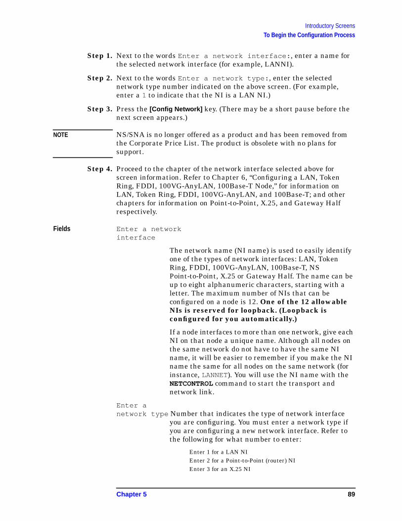
Introductory ScreensTo Begin the Configuration Process
Step 1. Next to the words Enter a network interface: , enter a name forthe selected network interface (for example, LANNI).
Step 2. Next to the words Enter a network type: , enter the selectednetwork type number indicated on the above screen. (For example,enter a 1 to indicate that the NI is a LAN NI.)
Step 3. Press the [Config Network] key. (There may be a short pause before thenext screen appears.)
NOTE NS/SNA is no longer offered as a product and has been removed fromthe Corporate Price List. The product is obsolete with no plans forsupport.
Step 4. Proceed to the chapter of the network interface selected above forscreen information. Refer to Chapter 6, “Configuring a LAN, TokenRing, FDDI, 100VG-AnyLAN, 100Base-T Node,” for information onLAN, Token Ring, FDDI, 100VG-AnyLAN, and 100Base-T; and otherchapters for information on Point-to-Point, X.25, and Gateway Halfrespectively.
Fields Enter a networkinterface
The network name (NI name) is used to easily identifyone of the types of network interfaces: LAN, TokenRing, FDDI, 100VG-AnyLAN, 100Base-T, NSPoint-to-Point, X.25 or Gateway Half. The name can beup to eight alphanumeric characters, starting with aletter. The maximum number of NIs that can beconfigured on a node is 12. One of the 12 allowableNIs is reserved for loopback. (Loopback isconfigured for you automatically.)
If a node interfaces to more than one network, give eachNI on that node a unique name. Although all nodes onthe same network do not have to have the same NIname, it will be easier to remember if you make the NIname the same for all nodes on the same network (forinstance, LANNET). You will use the NI name with theNETCONTROL command to start the transport andnetwork link.
Enter anetwork type Number that indicates the type of network interface
you are configuring. You must enter a network type ifyou are configuring a new network interface. Refer tothe following for what number to enter:
Enter 1 for a LAN NIEnter 2 for a Point-to-Point (router) NIEnter 3 for an X.25 NI
Chapter 5 89

Introductory ScreensTo Begin the Configuration Process
Enter 4 for an SNA NIEnter 5 for a Gateway Half NIEnter 6 for a Token Ring NIEnter 7 for an FDDI NIEnter 8 for 100VG-AnyLANEnter 9 for 100Base-T
90 Chapter 5

6 Configuring a LAN, Token Ring,FDDI, 100VG-AnyLAN, 100Base-T
Node
This chapter provides step-by-step instructions for configuring localarea network (LAN), Token Ring, Fiber Distributed Data Interface(FDDI), 100VG-AnyLAN, and 100Base-T links. This manual assumesthat you are using the guided configuration capabilities of NMMGR.
Figure 6-1 shows the screen flow for configuring LAN, Token Ring,FDDI, 100VG-AnyLAN, and 100Base-T screens. Screens unique to theconfiguration of LAN, Token Ring, FDDI, 100VG-AnyLAN and100Base-T are indicated by bold boxed screens. [FUNCTION] denotes thefunction key used at a screen to invoke the next screen on the screenflow.
Figure 6-1 Configuring Screen Flow
91

Configuring a LAN, Token Ring, FDDI, 100VG-AnyLAN, 100Base-T Node
Before using NMMGR to configure a link, you should complete theworksheets provided. See Chapter 4, “Planning for NodeConfiguration,” for more information on planning your configurationand filling out the configuration worksheets.
This chapter includes step-by-step instructions to help you perform thefollowing tasks:
• Begin the configuration process.
• Configure a LAN, Token Ring, FDDI, 100VG-AnyLAN, or 100Base-Tnetwork interfaces.
Once the above tasks are completed, refer to Chapter 10, “ValidatingNetwork Transport and Cross-Validating with SYSGEN,” forstep-by-step instructions to help you perform the following validationtasks:
• Validate the network transport configuration.
• Cross-validate in SYSGEN.
92 Chapter 6

Configuring a LAN, Token Ring, FDDI, 100VG-AnyLAN, 100Base-T NodeTo Configure a LAN Network Interface
To Configure a LAN Network InterfaceThe LAN Configuration screen (#41) in Figure 6-2 is displayed whenyou press the [Config Network] key at the Network TransportConfiguration screen (#42) with an NI type of 1 (LAN). Refer to Chapter5, “Introductory Screens,” for information on the Network TransportConfiguration screen.
Figure 6-2 LAN Configuration Screen
Step 1. In the IP address field, enter the internet protocol (IP) address for thenode being configured. An example of an address is:C 192.191.191 009 .
Step 2. The IP subnet mask is optional. If entering one, tab to the IP subnetmask field and enter the number in the same format as an IP address.
Step 3. The proxy node is optional. Enter Y only if your network hasinternetworks (networks with gateways) or non-HP nodes and you arenot using domain name services.
Step 4. Move to the Link name field. Enter a link name to represent the LANcard for which you are configuring a link. This name must be unique tothe node.
Step 5. Tab down to the field called Physical path of LANIC . Enter thephysical path number corresponding to the SPU slot number where theLAN interface controller card is located.
Chapter 6 93

Configuring a LAN, Token Ring, FDDI, 100VG-AnyLAN, 100Base-T NodeTo Configure a LAN Network Interface
Step 6. Tab down to the field called Enable Ethernet (Y/N) . By default,ethernet is enabled. Change the field to N if you do not want ethernetenabled.
Step 7. Tab down to field called Enable IEEE 802.3 (Y/N) . By default,IEEE 802.3 is enabled. Change the field to N if you do not wantIEEE 802.3 enabled.
Step 8. Press the [Save Data] key to save the LAN link configuration. If youneed to identify neighbor gateways, press the [Neighbor Gateways] keyand proceed to the section in this chapter called “To Identify NeighborGateways.” Otherwise, proceed to Chapter 10, “Validating NetworkTransport and Cross-Validating with SYSGEN,” and press the[Validate Netxport] key.
Optional KeysPress the [List NIs] key to list the names and types ofalready configured network interfaces.
Press the [Delete NI] key to remove a configured networkinterface from the configuration file.
Press the [Read Other NI] key to call up a previouslyconfigured Network Interface name.
Fields Node name Display only.
NetworkInterface NI)name Display only.
IP address The IP address is an address of a node on a network. AnIP address has two parts: a network portion and a nodeportion. The network portion must be the same for allnodes on a LAN network; the node portion must beunique for all nodes on a LAN network.
There are two methods of entering an internet protocol (IP) addresswithin NMMGR:
1. Enter the fully qualified IP address (for example, Class C,C 192.191.191 009 ).
OR
2. Enter only the network (nnn) and node (xxx) portions of the IPaddress as four positive integers between 0 and 255 separated byperiods or blanks (for example, 15.123.44.98 ).
You need not enter the following items as NMMGR will fill these in:
• Class A, B, C
• Leading zeros for the network and node portion of the IP address.
94 Chapter 6
Configuring a LAN, Token Ring, FDDI, 100VG-AnyLAN, 100Base-T NodeTo Configure a LAN Network Interface
HP assigns the network portion (initial nine digits) of IP addressesfrom ARPA Class C, though your addresses may also be of Classes Aor B. The complete formats are:
For Class C, the node portion of the IP address must be between 001and 254 .
If you are adding your NS 3000/iX node to an existing network, thenetwork portion of each node’s IP address should be the same. You willhave to find out what this is, and use it in the network portion of the IPaddress of your NS 3000/iX node. Also, you will need to know the nodeportions of the IP addresses of each of the nodes (usually they will benumbered sequentially, such as 001 , 002 , and so on), so that you canspecify a unique node portion for the IP address of your node. If youhave a network map, it should provide a record of such items as thenode name and IP address of each node. If there is no record, and if youwant to find out each node’s IP address, you will have to issue thefollowing command (NM capability required) on each of the nodes:
NETCONTROL NET=NIname;STATUS
One of the lines of output from this command tells you what thecomplete IP address is for that node; the last three digits are the uniquenode portion of the class C address.
NOTE To obtain a class B or C IP address, contact Government Systems,Incorporated (GSI). To obtain an application form, write GSI at theaddress below. Allow at least eight working days for GSI to process anIP address request.
Government Systems, Inc.Attn: Network Information Center7990 Boeing Ct.Vienna, VA 22183(800) 364-3642 or FAX (703) 821-6161
IP subnetmask An IP subnet mask is specified in the same format as
an IP address. The 32-bit mask is grouped in octetsexpressed as decimal integers and delimited by either aperiod (.) or a space. An IP mask is used when
Class A nnn xxx.xxx.xxx
B nnn.nnn xxx.xxx
C nnn.mmm.mmm xxx
Where: nnn = the network portion of the IP address andxxx = the node portion of the IP address.
Chapter 6 95

Configuring a LAN, Token Ring, FDDI, 100VG-AnyLAN, 100Base-T NodeTo Configure a LAN Network Interface
configuring subnetworks. The mask identifies whichbits of an IP address will be used to define asubnetwork. To determine these bits, you first need toestimate how many subnetworks and nodes persubnetwork you need. See Chapter 2, “NetworkingConcepts,” for details on deriving an IP subnet mask.
Proxy node Establishing a proxy node is a way of placing nodename and address mapping information in a singlelocation. If you are configuring an internetwork or anetwork with non-HP nodes, it may be easier to updateyour configurations if you have them located in acentral place, that is, the proxy node. On aninternetwork, the proxy node is usually a gateway. (It isnot necessary to configure a proxy node if you haveconfigured domain names. See Chapter 12,“Configuring Domain Name Files,” for information ondomain names.)
Link name The link name can have up to eight alphanumericcharacters and the first character must be alphabetic.
Physical Path ofLANIC The physical path number corresponds to the slot
location of a node’s local area network interfacecontroller (LANIC) card. Recommended slot locationsand physical path calculations vary according to thetype of HP 3000 system you are running. If you areunsure of the slot location or of the physical pathnumber to configure for your system, see your systemdocumentation or consult your Hewlett-Packard servicerepresentative.
Enable Ethernet?A Y in this field enables ethernet for the LAN. You canenable either ethernet or IEEE 802.3 or bothsimultaneously. One or the other must be enabled (bothfields may not be set to N). Ethernet is enabled bydefault.
Disabling Ethernet has the effect of disabling the ARPprotocol as well and you will need to handle name to IPaddress resolution by other means.
EnableIEEE 802.3? A Y in this field enables IEEE 802.3 for the LAN. You
can enable either IEEE 802.3 or ethernet or bothsimultaneously. One or the other must be enabled (bothfields may not be set to N). IEEE 802.3 is enabled bydefault.
96 Chapter 6

Configuring a LAN, Token Ring, FDDI, 100VG-AnyLAN, 100Base-T NodeTo Configure a LAN Network Interface
Disabling IEEE 802.3 has the effect of disabling theprobe protocol as well and you will need to handle nameto IP address resolution by other means.
Chapter 6 97
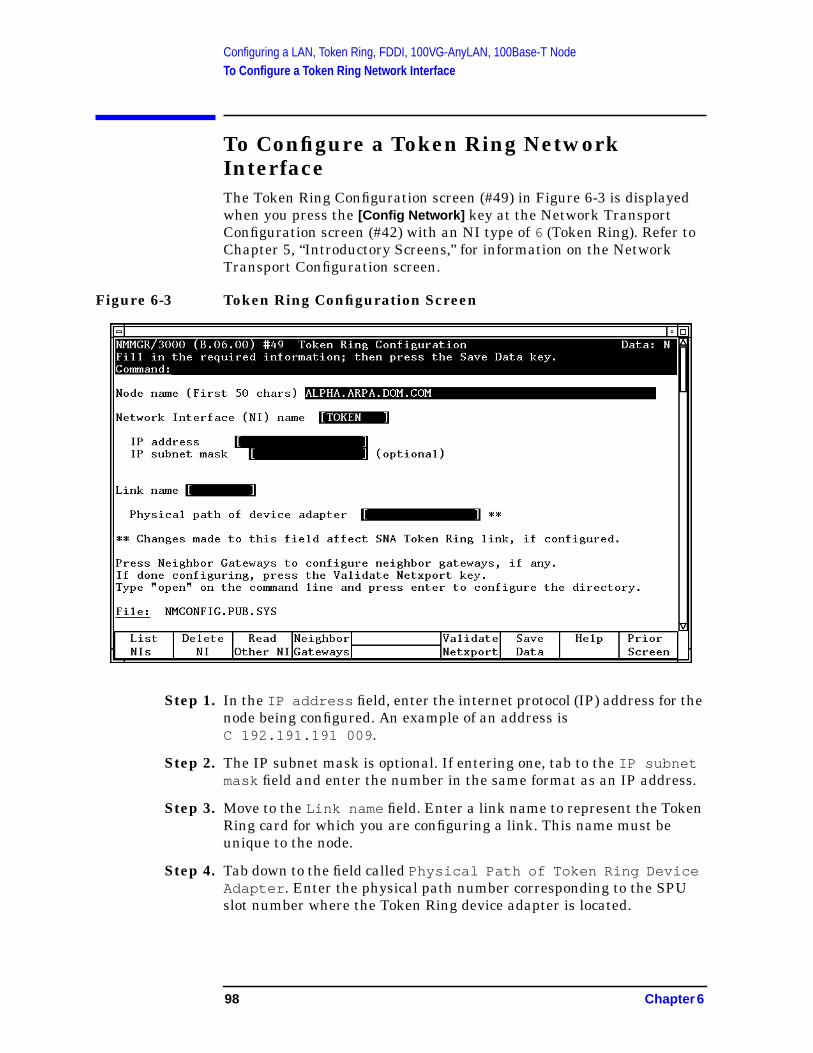
Configuring a LAN, Token Ring, FDDI, 100VG-AnyLAN, 100Base-T NodeTo Configure a Token Ring Network Interface
To Configure a Token Ring NetworkInterfaceThe Token Ring Configuration screen (#49) in Figure 6-3 is displayedwhen you press the [Config Network] key at the Network TransportConfiguration screen (#42) with an NI type of 6 (Token Ring). Refer toChapter 5, “Introductory Screens,” for information on the NetworkTransport Configuration screen.
Figure 6-3 Token Ring Configuration Screen
Step 1. In the IP address field, enter the internet protocol (IP) address for thenode being configured. An example of an address isC 192.191.191 009 .
Step 2. The IP subnet mask is optional. If entering one, tab to the IP subnetmask field and enter the number in the same format as an IP address.
Step 3. Move to the Link name field. Enter a link name to represent the TokenRing card for which you are configuring a link. This name must beunique to the node.
Step 4. Tab down to the field called Physical Path of Token Ring DeviceAdapter . Enter the physical path number corresponding to the SPUslot number where the Token Ring device adapter is located.
98 Chapter 6

Configuring a LAN, Token Ring, FDDI, 100VG-AnyLAN, 100Base-T NodeTo Configure a Token Ring Network Interface
NOTE If the same Token Ring card is being used for both NS and SNAcommunications, you must use the same value for this field as isconfigured for the SNA Link.
Step 5. Press the [Save Data] key to save the Token Ring link configuration. Ifyou need to identify neighbor gateways, press the [Neighbor Gateways]key and proceed to the section in the chapter called “To IdentifyNeighbor Gateways.” Otherwise, proceed to Chapter 10, “ValidatingNetwork Transport and Cross-Validating with SYSGEN,” and press the[Validate Netxport] key.
Optional KeysPress the [List NIs] key to list the names and types ofalready configured network interfaces.
Press the [Delete NI] key to remove a configured networkinterface from the configuration file.
Press the [Read Other NI] key to call up a previouslyconfigured Network Interface name.
Fields Node name Display only.
NetworkInterface(NI) name Display only.
IP address The IP address is an address of a node on a network. AnIP address has two parts: a network portion and a nodeportion. The network portion must be the same for allnodes on a LAN network; the node portion must beunique for all nodes on a LAN network.
HP assigns the network portion (initial nine digits) of IP addressesfrom ARPA Class C, though your addresses may also be of Classes A orB. The complete formats are:
For Class C, the node portion of the IP address must be between 001and 254 .
If you are adding your NS 3000/iX node to an existing network, thenetwork portion of each node’s IP address should be the same. You willhave to find out what this is, and use it in the network portion of the IP
Class A nnn xxx.xxx.xxx
B nnn.nnn xxx.xxx
C nnn.mmm.mmm xxx
Where: nnn = the network portion of the IP address andxxx = the node portion of the IP address.
Chapter 6 99

Configuring a LAN, Token Ring, FDDI, 100VG-AnyLAN, 100Base-T NodeTo Configure a Token Ring Network Interface
address of your NS 3000/iX node. Also, you will need to know the nodeportions of the IP addresses of each of the nodes (usually they will benumbered sequentially, such as 001 , 002 , and so on), so that you canspecify a unique node portion for the IP address of your node. If youhave a network map, it should provide a record of such items as thenode name and IP address of each node. If there is no record, and if youwant to find out each node’s IP address, you will have to issue thefollowing command (NM capability required) on each of the nodes:
NETCONTROL NET=NIname;STATUS
One of the lines of output from this command tells you what thecomplete IP address is for that node; the last three digits are the uniquenode portion of the class C address.
NOTE To obtain a class B or C IP address, contact Government Systems,Incorporated (GSI). To obtain an application form, write GSI at theaddress below. Allow at least eight working days for GSI to process anIP address request.
Government Systems, Inc.Attn: Network Information Center7990 Boeing Ct.Vienna, VA 22183(800) 364-3642 (703) 821-6161
IP subnetmask An IP subnet mask is specified in the same format as
an IP address. The 32-bit mask is grouped in octetsexpressed as decimal integers and delimited by either aperiod (.) or a space. An IP mask is used whenconfiguring subnetworks. The mask identifies whichbits of the IP address comprise the network andsubnetwork portion.
Link name The link name can have up to eight alphanumericcharacters and the first character must be alphabetic.
NOTE If the same Token Ring card is being used for both NS and SNAcommunications, you must use the same name in this field as isconfigured for the SNA Link.
Physical Path ofDevice Adapter The physical path number corresponds to the slot
location of a node’s device adapter. Recommended slotlocations and physical path calculations vary accordingto the type of HP 3000 system you are running. If youare unsure of the slot location or of the physical pathnumber to configure for your system, see your systemdocumentation or consult your Hewlett-Packard servicerepresentative.
100 Chapter 6
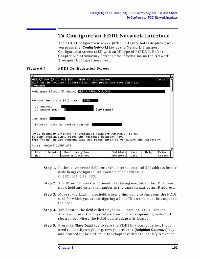
Configuring a LAN, Token Ring, FDDI, 100VG-AnyLAN, 100Base-T NodeTo Configure an FDDI Network Interface
To Configure an FDDI Network InterfaceThe FDDI Configuration screen (#201) in Figure 6-4 is displayed whenyou press the [Config Network] key at the Network TransportConfiguration screen (#42) with an NI type of 7 (FDDI). Refer toChapter 5, “Introductory Screens,” for information on the NetworkTransport Configuration screen.
Figure 6-4 FDDI Configuration Screen
Step 1. In the IP address field, enter the internet protocol (IP) address for thenode being configured. An example of an address isC 192.191.191 009 .
Step 2. The IP subnet mask is optional. If entering one, tab to the IP subnetmask field and enter the number in the same format as an IP address.
Step 3. Move to the Link name field. Enter a link name to represent the FDDIcard for which you are configuring a link. This name must be unique tothe node.
Step 4. Tab down to the field called Physical Path of FDDI DeviceAdapter . Enter the physical path number corresponding to the SPUslot number where the FDDI device adapter is located.
Step 5. Press the [Save Data] key to save the FDDI link configuration. If youneed to identify neighbor gateways, press the [Neighbor Gateways] keyand proceed to the section in the chapter called “To Identify Neighbor
Chapter 6 101

Configuring a LAN, Token Ring, FDDI, 100VG-AnyLAN, 100Base-T NodeTo Configure an FDDI Network Interface
Gateways.” Otherwise, proceed to Chapter 10, “Validating NetworkTransport and Cross-Validating with SYSGEN,” and press the[Validate Netxport] key.
Optional KeysPress the [List NIs] key to list the names and types ofalready configured network interfaces.
Press the [Delete NI] key to remove a configured networkinterface from the configuration file.
Press the [Read Other NI] key to call up a previouslyconfigured Network Interface name.
Fields Node name Display only.
NetworkInterface(NI) name Display only.
IP address The IP address is an address of a node on a network. AnIP address has two parts: a network portion and a nodeportion. The network portion must be the same for allnodes on a FDDI network; the node portion must beunique for all nodes on a FDDI network.
There are two methods of entering an internet protocol (IP) addresswithin NMMGR:
1. Enter the fully qualified IP address (for example, Class C,C 192.191.191 009 ).
OR
2. Enter only the network (nnn) and node (xxx) portions of the IPaddress as four positive integers between 0 and 255 separated byperiods or blanks (for example, 15.123.44.98 ).
You need not enter the following items as NMMGR will fill these in:
• Class A, B, C
• Leading zeros for the network and node portion of the IP address.
HP assigns the network portion (initial nine digits) of IP addressesfrom ARPA Class C, though your addresses may also be of Classes A orB. The complete formats are:
Class A nnn xxx.xxx.xxx
102 Chapter 6
Configuring a LAN, Token Ring, FDDI, 100VG-AnyLAN, 100Base-T NodeTo Configure an FDDI Network Interface
For Class C, the node portion of the IP address must be between 001and 254 .
If you are adding your NS 3000/iX node to an existing network, thenetwork portion of each node’s IP address should be the same. You willhave to find out what this is, and use it in the network portion of the IPaddress of your NS 3000/iX node. Also, you will need to know the nodeportions of the IP addresses of each of the nodes (usually they will benumbered sequentially, such as 001 , 002 , and so on), so that you canspecify a unique node portion for the IP address of your node. If youhave a network map, it should provide a record of such items as thenode name and IP address of each node. If there is no record, and if youwant to find out each node’s IP address, you will have to issue thefollowing command (NM capability required) on each of the nodes:
NETCONTROL NET=NIname;STATUS
One of the lines of output from this command tells you what thecomplete IP address is for that node; the last three digits are the uniquenode portion of the class C address.
NOTE To obtain a class B or C IP address, contact Government Systems,Incorporated (GSI). To obtain an application form, write GSI at theaddress below. Allow at least eight working days for GSI to process anIP address request.
Government Systems, Inc.Attn: Network Information Center14200 Park Meadow DriveChantilly, CA 22021(800) 364-3642 (703) 802-4535
IP subnetmask An IP subnet mask is specified in the same format as
an IP address. The 32-bit mask is grouped in octetsexpressed as decimal integers and delimited by either aperiod (.) or a space. An IP mask is used whenconfiguring subnetworks. The mask identifies whichbits of the IP address comprise the network andsubnetwork portion.
Link name The link name can have up to eight alphanumericcharacters and the first character must be alphabetic.
B nnn.nnn xxx.xxx
C nnn.mmm.mmm xxx
Where: nnn = the network portion of the IP address andxxx = the node portion of the IP address.
Chapter 6 103
Configuring a LAN, Token Ring, FDDI, 100VG-AnyLAN, 100Base-T NodeTo Configure an FDDI Network Interface
Physical Pathof FDDIDeviceAdapter The physical path number corresponds to the slot
location of a node’s FDDI device adapter. Recommendedslot locations and physical path calculations varyaccording to the type of HP 3000 system you arerunning. If you are unsure of the slot location or of thephysical path number to configure for your system, seeyour system documentation or consult yourHewlett-Packard service representative.
104 Chapter 6

Configuring a LAN, Token Ring, FDDI, 100VG-AnyLAN, 100Base-T NodeTo Configure a 100VG-AnyLAN Network Interface
To Configure a 100VG-AnyLAN NetworkInterfaceThe 100VG-AnyLAN Configuration screen (#287) in Figure 6-5 isdisplayed when you press the [Config Network] key at the NetworkTransport Configuration screen (#42) with an NI type of 8(100VG-AnyLAN). Refer to Chapter 5, “Introductory Screens,” forinformation on the Network Transport Configuration screen.
Figure 6-5 100VG-AnyLAN Configuration Screen
Step 1. In the IP address field, enter the internet protocol (IP) address for thenode being configured. An example of an address is:C 192.191.191 009 .
Step 2. The IP subnet mask is optional. If entering one, tab to the IP subnetmask field and enter the number in the same format as an IP address.
Step 3. Move to the Link name field. Enter a link name to represent the100VG-AnyLAN card for which you are configuring a link. This namemust be unique to the node.
Step 4. Tab down to the field called Physical path of device adapter .
Step 5. Press the [Save Data] key to save the 100VG-AnyLAN linkconfiguration. If you need to identify neighbor gateways, press the[Neighbor Gateways] key and proceed to the section in this chapter called
Chapter 6 105
Configuring a LAN, Token Ring, FDDI, 100VG-AnyLAN, 100Base-T NodeTo Configure a 100VG-AnyLAN Network Interface
“To Identify Neighbor Gateways.” Otherwise, proceed to Chapter 10,“Validating Network Transport and Cross-Validating with SYSGEN,”and press the [Validate Netxport] key.
Optional KeysPress the [List NIs] key to list the names and types ofalready configured network interfaces.
Press the [Delete NI] key to remove a configured networkinterface from the configuration file.
Press the [Read Other NI] key to call up a previouslyconfigured Network Interface name.
Fields Node name Display only.
NetworkInterface NI)name Display only.
IP address The IP address is an address of a node on a network. AnIP address has two parts: a network portion and a nodeportion. The network portion must be the same for allnodes on a LAN network; the node portion must beunique for all nodes on a LAN network.
There are two methods of entering an internet protocol (IP) addresswithin NMMGR:
1. Enter the fully qualified IP address (for example, Class C,C 192.191.191 009 ).
OR
2. Enter only the network (nnn) and node (xxx) portions of the IPaddress as four positive integers between 0 and 255 separated byperiods or blanks (for example, 15.123.44.98 ).
You need not enter the following items as NMMGR will fill these in:
• Class A, B, C
• Leading zeros for the network and node portion of the IP address.
HP assigns the network portion (initial nine digits) of IP addressesfrom ARPA Class C, though your addresses may also be of Classes Aor B. The complete formats are:
Class A nnn xxx.xxx.xxx
106 Chapter 6
Configuring a LAN, Token Ring, FDDI, 100VG-AnyLAN, 100Base-T NodeTo Configure a 100VG-AnyLAN Network Interface
For Class C, the node portion of the IP address must be between 001and 254 .
If you are adding your NS 3000/iX node to an existing network, thenetwork portion of each node’s IP address should be the same. You willhave to find out what this is, and use it in the network portion of the IPaddress of your NS 3000/iX node. Also, you will need to know the nodeportions of the IP addresses of each of the nodes (usually they will benumbered sequentially, such as 001 , 002 , and so on), so that you canspecify a unique node portion for the IP address of your node. If youhave a network map, it should provide a record of such items as thenode name and IP address of each node. If there is no record, and if youwant to find out each node’s IP address, you will have to issue thefollowing command (NM capability required) on each of the nodes:
NETCONTROL NET=NIname;STATUS
One of the lines of output from this command tells you what thecomplete IP address is for that node; the last three digits are the uniquenode portion of the class C address.
NOTE To obtain a class B or C IP address, contact Government Systems,Incorporated (GSI). To obtain an application form, write GSI at theaddress below. Allow at least eight working days for GSI to process anIP address request.
Government Systems, Inc.Attn: Network Information Center7990 Boeing Ct.Vienna, VA 22183(800) 364-3642 (703) 821-6161
IP subnetmask An IP subnet mask is specified in the same format as
an IP address. The 32-bit mask is grouped in octetsexpressed as decimal integers and delimited by either aperiod (.) or a space. An IP mask is used whenconfiguring subnetworks. The mask identifies whichbits of an IP address will be used to define asubnetwork. To determine these bits, you first need toestimate how many subnetworks and nodes persubnetwork you need. See Chapter 2, “NetworkingConcepts,” for details on deriving an IP subnet mask.
B nnn.nnn xxx.xxx
C nnn.mmm.mmm xxx
Where: nnn = the network portion of the IP address andxxx = the node portion of the IP address.
Chapter 6 107

Configuring a LAN, Token Ring, FDDI, 100VG-AnyLAN, 100Base-T NodeTo Configure a 100VG-AnyLAN Network Interface
Proxy node Establishing a proxy node is a way of placing nodename and address mapping information in a singlelocation. If you are configuring an internetwork or anetwork with non-HP nodes, it may be easier to updateyour configurations if you have them located in acentral place, that is, the proxy node. On aninternetwork, the proxy node is usually a gateway. (It isnot necessary to configure a proxy node if you haveconfigured domain names. See Chapter 12,“Configuring Domain Name Files,” for information ondomain names.)
Link name The link name can have up to eight alphanumericcharacters and the first character must be alphabetic.
Physical Path ofLANIC The physical path number corresponds to the slot
location of a node’s local area network interfacecontroller (LANIC) card. Recommended slot locationsand physical path calculations vary according to thetype of HP 3000 system you are running. If you areunsure of the slot location or of the physical pathnumber to configure for your system, see your systemdocumentation or consult your Hewlett-Packard servicerepresentative.
Enable Ethernet?A Y in this field enables ethernet for the LAN. You canenable either ethernet or IEEE 802.3 or bothsimultaneously. One or the other must be enabled (bothfields may not be set to N). Ethernet is enabled bydefault.
Disabling Ethernet has the effect of disabling the ARPprotocol as well and you will need to handle name to IPaddress resolution by other means.
EnableIEEE 802.3? A Y in this field enables IEEE 802.3 for the LAN. You
can enable either IEEE 802.3 or ethernet or bothsimultaneously. One or the other must be enabled (bothfields may not be set to N). IEEE 802.3 is enabled bydefault.
Disabling IEEE 802.3 has the effect of disabling theprobe protocol as well and you will need to handle nameto IP address resolution by other means.
108 Chapter 6

Configuring a LAN, Token Ring, FDDI, 100VG-AnyLAN, 100Base-T NodeTo Configure a 100Base-T Network Interface
To Configure a 100Base-T NetworkInterfaceThe 100Base-T Configuration screen (#297) in Figure 6-6 is displayedwhen you press the [Config Network] key at the Network TransportConfiguration screen (#42) with an NI type of 9 (100Base-T). Refer toChapter 5, “Introductory Screens,” for information on the NetworkTransport Configuration screen.
Figure 6-6 100Base-T Configuration Screen
Step 1. In the IP address field, enter the internet protocol (IP) address for thenode being configured. An example of an address is:C 192.191.191 009 .
Step 2. The IP subnet mask is optional. If entering one, tab to the IP subnetmask field and enter the number in the same format as an IP address.
Step 3. The proxy node is optional. Enter Y only if your network hasinternetworks (networks with gateways) or non-HP nodes and you arenot using domain name services.
Step 4. Move to the Link name field. Enter a link name to represent the LANcard for which you are configuring a link. This name must be unique tothe node.
Step 5. Tab down to the field called Physical path of device adapter .
Chapter 6 109
Configuring a LAN, Token Ring, FDDI, 100VG-AnyLAN, 100Base-T NodeTo Configure a 100Base-T Network Interface
Step 6. Tab down to the field called Enable Ethernet (Y/N) . By default,ethernet is enabled. Change the field to N if you do not want ethernetenabled.
Step 7. Tab down to field called Enable IEEE 802.3 (Y/N) . By default,IEEE 802.3 is enabled. Change the field to N if you do not wantIEEE 802.3 enabled.
Step 8. Press the [Save Data] key to save the LAN link configuration. If youneed to identify neighbor gateways, press the [Neighbor Gateways] keyand proceed to the section in this chapter called “To Identify NeighborGateways.” Otherwise, proceed to Chapter 10, “Validating NetworkTransport and Cross-Validating with SYSGEN,” and press the[Validate Netxport] key.
Optional KeysPress the [List NIs] key to list the names and types ofalready configured network interfaces.
Press the [Delete NI] key to remove a configured networkinterface from the configuration file.
Press the [Read Other NI] key to call up a previouslyconfigured Network Interface name.
Fields Node name Display only.
NetworkInterface NI)name Display only.
IP address The IP address is an address of a node on a network. AnIP address has two parts: a network portion and a nodeportion. The network portion must be the same for allnodes on a LAN network; the node portion must beunique for all nodes on a LAN network.
There are two methods of entering an internet protocol (IP) addresswithin NMMGR:
1. Enter the fully qualified IP address (for example, Class C,C 192.191.191 009 ).
OR
2. Enter only the network (nnn) and node (xxx) portions of the IPaddress as four positive integers between 0 and 255 separated byperiods or blanks (for example, 15.123.44.98 ).
You need not enter the following items as NMMGR will fill these in:
• Class A, B, C
• Leading zeros for the network and node portion of the IP address.
110 Chapter 6

Configuring a LAN, Token Ring, FDDI, 100VG-AnyLAN, 100Base-T NodeTo Configure a 100Base-T Network Interface
HP assigns the network portion (initial nine digits) of IP addressesfrom ARPA Class C, though your addresses may also be of Classes Aor B. The complete formats are:
For Class C, the node portion of the IP address must be between 001and 254 .
If you are adding your NS 3000/iX node to an existing network, thenetwork portion of each node’s IP address should be the same. You willhave to find out what this is, and use it in the network portion of the IPaddress of your NS 3000/iX node. Also, you will need to know the nodeportions of the IP addresses of each of the nodes (usually they will benumbered sequentially, such as 001 , 002 , and so on), so that you canspecify a unique node portion for the IP address of your node. If youhave a network map, it should provide a record of such items as thenode name and IP address of each node. If there is no record, and if youwant to find out each node’s IP address, you will have to issue thefollowing command (NM capability required) on each of the nodes:
NETCONTROL NET=NIname;STATUS
One of the lines of output from this command tells you what thecomplete IP address is for that node; the last three digits are the uniquenode portion of the class C address.
NOTE To obtain a class B or C IP address, contact Government Systems,Incorporated (GSI). To obtain an application form, write GSI at theaddress below. Allow at least eight working days for GSI to process anIP address request.
Government Systems, Inc.Attn: Network Information Center7990 Boeing Ct.Vienna, VA 22183(800) 364-3642 (703) 821-6161
IP subnetmask An IP subnet mask is specified in the same format as
an IP address. The 32-bit mask is grouped in octetsexpressed as decimal integers and delimited by either aperiod (.) or a space. An IP mask is used when
Class A nnn xxx.xxx.xxx
B nnn.nnn xxx.xxx
C nnn.mmm.mmm xxx
Where: nnn = the network portion of the IP address andxxx = the node portion of the IP address.
Chapter 6 111
Configuring a LAN, Token Ring, FDDI, 100VG-AnyLAN, 100Base-T NodeTo Configure a 100Base-T Network Interface
configuring subnetworks. The mask identifies whichbits of an IP address will be used to define asubnetwork. To determine these bits, you first need toestimate how many subnetworks and nodes persubnetwork you need. See Chapter 2, “NetworkingConcepts,” for details on deriving an IP subnet mask.
Proxy node Establishing a proxy node is a way of placing nodename and address mapping information in a singlelocation. If you are configuring an internetwork or anetwork with non-HP nodes, it may be easier to updateyour configurations if you have them located in acentral place, that is, the proxy node. On aninternetwork, the proxy node is usually a gateway. (It isnot necessary to configure a proxy node if you haveconfigured domain names. See Chapter 12,“Configuring Domain Name Files,” for information ondomain names.)
Link name The link name can have up to eight alphanumericcharacters and the first character must be alphabetic.
Physical Path ofLANIC The physical path number corresponds to the slot
location of a node’s local area network interfacecontroller (LANIC) card. Recommended slot locationsand physical path calculations vary according to thetype of HP 3000 system you are running. If you areunsure of the slot location or of the physical pathnumber to configure for your system, see your systemdocumentation or consult your Hewlett-Packard servicerepresentative.
Enable Ethernet?A Y in this field enables ethernet for the LAN. You canenable either ethernet or IEEE 802.3 or bothsimultaneously. One or the other must be enabled (bothfields may not be set to N). Ethernet is enabled bydefault.
Disabling Ethernet has the effect of disabling the ARPprotocol as well and you will need to handle name to IPaddress resolution by other means.
EnableIEEE 802.3? A Y in this field enables IEEE 802.3 for the LAN. You
can enable either IEEE 802.3 or ethernet or bothsimultaneously. One or the other must be enabled (bothfields may not be set to N). IEEE 802.3 is enabled bydefault.
112 Chapter 6

Configuring a LAN, Token Ring, FDDI, 100VG-AnyLAN, 100Base-T NodeTo Configure a 100Base-T Network Interface
Disabling IEEE 802.3 has the effect of disabling theprobe protocol as well and you will need to handle nameto IP address resolution by other means.
Chapter 6 113
Configuring a LAN, Token Ring, FDDI, 100VG-AnyLAN, 100Base-T NodeTo Configure Neighbor Gateways
To Configure Neighbor GatewaysYou need to visit the next two screens only if you are configuring anon-gateway node that is on the same network as a gateway. In thiscase, the non-gateway node needs to know the identity of any neighborgateway. Neighbor gateways can be either full or half gateways.
Gateways that are on the same network are called neighborgateways. A non-gateway node on a LAN, Token Ring, FDDI,100VG-AnyLAN, or 100Base-T network may need to go through aneighbor gateway in order to send messages to an entirely differentnetwork. (Two nodes are on the same network if the network portionof their IP addresses are the same.) All LAN, Token Ring, FDDI,100VG-AnyLAN or 100Base-T nodes that are on the same network as aneighbor gateway need to know the identity of any neighbor gateways.When you configure a LAN, Token Ring, FDDI, 100VG-AnyLAN, or100Base-T node, you enter into its configuration the identity of anyaccessible neighbor gateways that share the same network. Theidentified gateways may be either full or half gateways.
You may designate gateways as default gateways. Messages for anetwork will be routed to a default gateway if there is no gatewayconfigured for the destination network. The default gateway will thenattempt to locate the destination of the message.
To Identify Neighbor Gateways (If Any ArePresent)The Neighbor Gateways screen (#152) in Figure 6-7 is displayed whenyou press the [Neighbor Gateways] key at the selected configurationscreen for the LAN, Token Ring, FDDI, 100VG-AnyLAN, and100Base-T via screen numbers 41, 49, 201, 296, and 306 respectively.
114 Chapter 6

Configuring a LAN, Token Ring, FDDI, 100VG-AnyLAN, 100Base-T NodeTo Configure Neighbor Gateways
Figure 6-7 Neighbor Gateways Screen
Step 1. In the Gateway name field, enter the name of a gateway that is on thesame network as the node that you are configuring. (Nodes are on thesame network if the network portions of their IP addresses are thesame.).
Step 2. If you are adding the identified gateway for the first time, press the[Add] key. If you are modifying the configuration of this node, press the[Modify] key. The Neighbor Gateway Reachable Networks screen will bedisplayed. Proceed to “Identify Neighbor Gateway ReachableNetworks.”
Step 3. Repeat steps 1 and 2 for each gateway that is on the same network asthe node that you are configuring. When you have finished, press the[Next Screen] key to return to the selected configuration screen (LAN,Token Ring, FDDI, 100VG-AnyLAN, or 100Base-T) and proceed toChapter 10, “Validating Network Transport and Cross-Validating withSYSGEN,”
Fields Gateway name Each gateway name can be as long as eightalphanumeric characters. The first character must bealphabetic.
Chapter 6 115

Configuring a LAN, Token Ring, FDDI, 100VG-AnyLAN, 100Base-T NodeTo Configure Neighbor Gateways
To Identify Neighbor Gateway ReachableNetworksThe Neighbor Gateway Reachable Networks screen (#158) in Figure 6-8is displayed when you press the [Add] or [Modify] key for a valid gatewayname from the Neighbor Gateways screen (#152) in Figure 6-7.
Figure 6-8 Neighbor Gateway Reachable Networks Screen
Step 1. In the Neighbor Gateway IP Internet Address field, enter the IPaddress of the gateway specified on the Neighbor Gateways screen.C 192.191.191 009 is a typical address.
Step 2. In the IP Network Address fields under the title ConfiguredReachable Networks , enter the IP addresses of all the remotenetworks that can be reached through the gateway whose IP address isconfigured in the previous field. If you want to designate this gatewayas a default gateway, enter an at sign (@) in one of the fields as well.
Step 3. The IP subnet mask is optional. If entering one, tab to the next field. Inthe IP subnet mask field, enter the number in the same format as anIP address.
Step 4. In the field labeled Hops, enter the number of hops (full gateways)needed to get to the target network. Two partner gateway halves countas one hop.
116 Chapter 6

Configuring a LAN, Token Ring, FDDI, 100VG-AnyLAN, 100Base-T NodeTo Configure Neighbor Gateways
Step 5. Repeat steps 2, 3, and 4 for each remote reachable network. Theinformation configured in this screen can extend to more thanone page, if necessary, to allow configuration of up to 2550reachable networks per link (255 pages and 10 reachable netsper page). If you need to configure more than 10 networks, press the[Save Data] key then press the [Next Page] key to enter more networks.
Step 6. After you have finished entering the IP addresses of all the reachablenetworks, press the [Save Data] key. Press the [Prior Screen] key toreturn to the Neighbor Gateways screen.
Step 7. Back at the Neighbor Gateways screen, after you have finished addingall of the neighboring gateways, press the [Prior Screen] key to return tothe selected configuration screen (LAN, Token Ring, FDDI,100VG-AnyLAN, or 100Base-T). Proceed to Chapter 10, “ValidatingNetwork Transport and Cross-Validating with SYSGEN,”
Fields If you have identified any neighbor gateways, then you will also beidentifying: 1) the IP Network Addresses of all of the networks that youcan reach through that gateway, and 2) the number of hops(corresponding to the number of gateways) that a packet passesthrough to reach a remote network from the local network. Twogateway halves count as one hop.
Neighbor GatewayIP InternetAddress The IP address of the gateway whose name you have
specified on the Neighbor Gateways Screen. The IPaddress is in the same format as the selectedconfiguration screen (LAN, Token Ring, FDDI,100VG-AnyLAN, or 100Base-T).
IP NetworkAddress In the fields under this heading, you list the IP
addresses of all of the networks that you will be able toreach through the gateway you are configuring. Youalso use this field to indicate whether or not thegateway is to serve as a default gateway byentering an at sign (@) to specify that it is adefault gateway. Only one gateway can bedesignated as a default gateway for each HP 3000Series 900 system.
IP Mask(Optional) The fields under this heading allow you to specify a
subnet mask for each reachable network. This mask isoptional.
Hops In the fields under this heading, enter the number ofhops corresponding to the number of gateways that apacket travels to reach a remote network from a localnetwork.
Chapter 6 117

Configuring a LAN, Token Ring, FDDI, 100VG-AnyLAN, 100Base-T NodeTo Configure Neighbor Gateways
118 Chapter 6
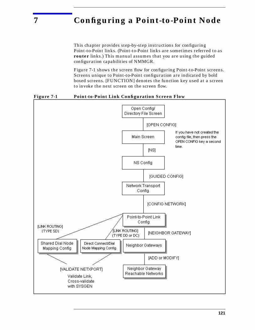
7 Configuring a Point-to-Point Node
This chapter provides step-by-step instructions for configuringPoint-to-Point links. (Point-to-Point links are sometimes referred to asrouter links.) This manual assumes that you are using the guidedconfiguration capabilities of NMMGR.
Figure 7-1 shows the screen flow for configuring Point-to-Point screens.Screens unique to Point-to-Point configuration are indicated by boldboxed screens. [FUNCTION] denotes the function key used at a screento invoke the next screen on the screen flow.
Figure 7-1 Point-to-Point Link Configuration Screen Flow
121

Configuring a Point-to-Point Node
Before using NMMGR to configure a link, you should complete theworksheets provided. See Chapter 4, “Planning for NodeConfiguration,” for more information on planning your configurationand filling out the configuration worksheets.
This chapter includes step-by-step instructions to help you perform thefollowing tasks:
• Begin the configuration process.
• Configure a Point-to-Point network interface.
• Configure neighbor gateways.
• Configure node mapping.
Once the above tasks are completed, refer to Chapter 10, “ValidatingNetwork Transport and Cross-Validating with SYSGEN,” forstep-by-step instructions to help you perform the following validationtasks:
• Validate the network transport configuration.
• Cross-validate in SYSGEN.
122 Chapter 7
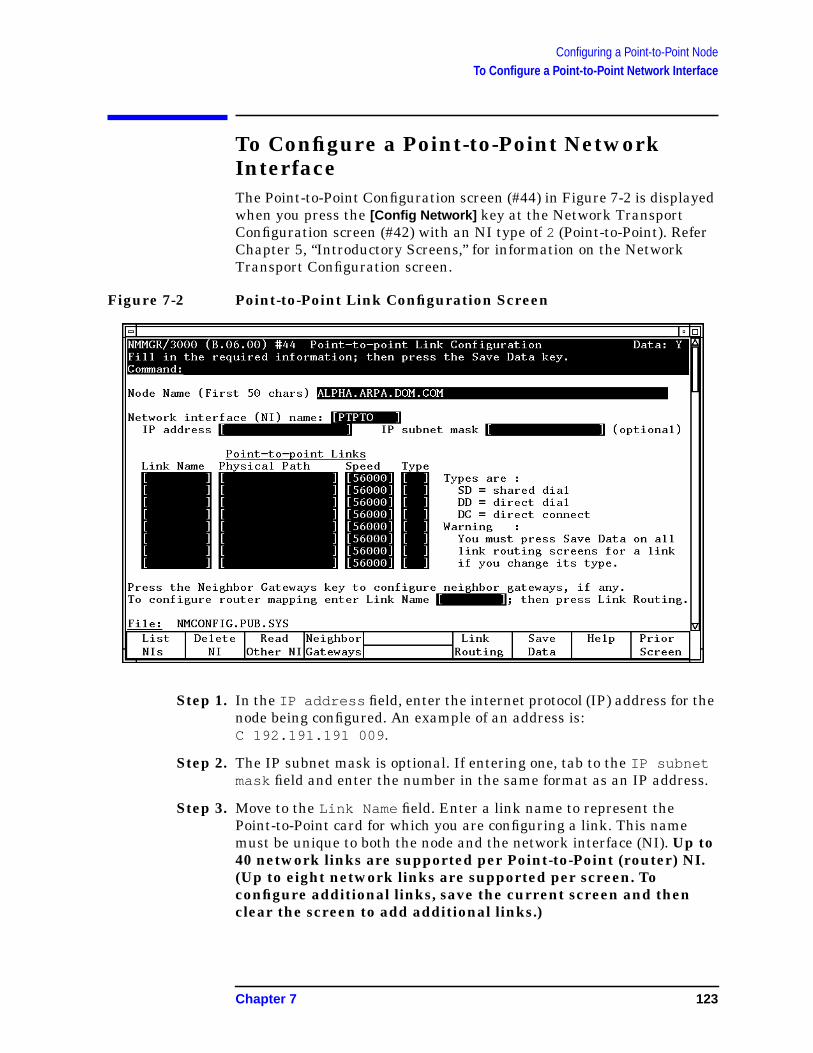
Configuring a Point-to-Point NodeTo Configure a Point-to-Point Network Interface
To Configure a Point-to-Point NetworkInterfaceThe Point-to-Point Configuration screen (#44) in Figure 7-2 is displayedwhen you press the [Config Network] key at the Network TransportConfiguration screen (#42) with an NI type of 2 (Point-to-Point). ReferChapter 5, “Introductory Screens,” for information on the NetworkTransport Configuration screen.
Figure 7-2 Point-to-Point Link Configuration Screen
Step 1. In the IP address field, enter the internet protocol (IP) address for thenode being configured. An example of an address is:C 192.191.191 009 .
Step 2. The IP subnet mask is optional. If entering one, tab to the IP subnetmask field and enter the number in the same format as an IP address.
Step 3. Move to the Link Name field. Enter a link name to represent thePoint-to-Point card for which you are configuring a link. This namemust be unique to both the node and the network interface (NI). Up to40 network links are supported per Point-to-Point (router) NI.(Up to eight network links are supported per screen. Toconfigure additional links, save the current screen and thenclear the screen to add additional links.)
Chapter 7 123
Configuring a Point-to-Point NodeTo Configure a Point-to-Point Network Interface
Step 4. Tab down to the Physical Path field. Enter the physical path numbercorresponding to the SPU slot number of the programmable serialinterface (PSI) card.
Step 5. Tab to the Speed field. Enter the line transmission speed of this link.
Step 6. Tab to the Type field. Enter DD for direct dial, SD for shared dial or DCfor direct connection.
Step 7. Press the [Save Data] key to record the data you have entered.
Step 8. If you need to identify neighbor gateways, press the [Neighbor Gateways]key and proceed to the section in this chapter called “To ConfigureNeighbor Gateways.”
Step 9. If you have already configured neighbor gateways for this link or yournetwork contains no neighbor gateways, press the [Link Routing] keyand proceed to the section in this chapter titled “To Configure NodeMapping.”
Optional KeysPress the [List NIs] key to list the names and types ofalready configured network interfaces.
Press the [Delete NI] key to remove a configured networkinterface from the configuration file.
Press the [Read Other NI] key to call up a previouslyconfigured Network Interface name.
Fields Node name Display only.
NetworkInterface(NI) name Display only.
IP address The IP address is an address of a node on a network. AnIP address has two parts: a network portion and a nodeportion. The network portion must be the same for allnodes on a LAN network; the node portion must beunique for all nodes on a LAN network.
There are two methods of entering an internet protocol (IP) addresswithin NMMGR:
1. Enter the fully qualified IP address (for example, Class C,C 192.191.191 009 ).
OR
2. Enter only the network (nnn) and node (xxx) portions of the IPaddress as four positive integers between 0 and 255 separated byperiods or blanks (for example, 15.123.44.98 ).
124 Chapter 7
Configuring a Point-to-Point NodeTo Configure a Point-to-Point Network Interface
You need not enter the following items as NMMGR will fill these in:
• Class A, B, C
• Leading zeros for the network and node portion of the IP address.
HP assigns the network portion (initial nine digits) of IP addressesfrom ARPA Class C, though your addresses may also be of Classes A orB. The complete formats are:
For Class C, the node portion of the IP address must be between 001and 254 .
If you are adding your NS 3000/iX node to an existing network, thenetwork portion of each node’s IP address should be the same. You willhave to find out what this is, and use it in the network portion of the IPaddress of your NS 3000/iX node. Also, you will need to know the nodeportions of the IP addresses of each of the nodes (usually they will benumbered sequentially, such as 001 , 002 , and so on), so that you canspecify a unique node portion for the IP address of your node. If youhave a network map, it should provide a record of such items as thenode name and IP address of each node. If there is no record, and if youwant to find out each node’s IP address, you will have to issue thefollowing command (NM capability required) on each of the nodes:
NETCONTROL NET=NIname;STATUS
One of the lines of output from this command tells you what thecomplete IP address is for that node; the last three digits are the uniquenode portion of the class C address.
NOTE To obtain a class B or C IP address, contact Government Systems,Incorporated (GSI). To obtain an application form, write GSI at theaddress below. Allow at least eight working days for GSI to process anIP address request.
Government Systems, Inc.Attn: Network Information Center7990 Boeing Ct.Vienna, VA 22183(800) 364-3642 (703) 821-6161
Class A nnn xxx.xxx.xxx
B nnn.nnn xxx.xxx
C nnn.mmm.mmm xxx
Where: nnn = the network portion of the IP address andxxx = the node portion of the IP address.
Chapter 7 125
Configuring a Point-to-Point NodeTo Configure a Point-to-Point Network Interface
IP subnetmask An IP subnet mask is specified in the same format as
an IP address. The 32-bit mask is grouped in octetsexpressed as decimal integers and delimited by either aperiod (.) or a space. An IP mask is used whenconfiguring subnetworks. The mask identifies whichbits of an IP address will be used to define asubnetwork. To determine these bits, you first need toestimate how many subnetworks and nodes persubnetwork you need. See Chapter 2, “NetworkingConcepts,” for details on deriving an IP subnet mask.
Link name The link name can have up to eight alphanumericcharacters and the first character must be alphabetic.
Physical PathThe physical path number corresponds to the slotlocation of a node’s programmable serial interface (PSI)card. Recommended slot locations and physical pathcalculations vary according to the type of HP 3000system you are running. If you are unsure of the slotlocation or of the physical path number to configure foryour system, see your system documentation or consultyour Hewlett-Packard service representative.
Speed The line transmission speed is given in bits per second.For direct connect the value, must be supported by thecable. Values are 1200, 2400, 4800, 9600, 19200, 38400,56000, and 64000. The default is 56000.
Type Enter DD (direct dial) if you always want to call thesame host over a dial link. If you choose DD the remotehost does not have to be adjacent and other nodes canbe accessed through the remote host. Enter SD if youwant to call more than one adjacent remote node over adial link without reconfiguring. If you choose SD, noother remote nodes can be accessed through the remotehost; it is an end point in the connection. Enter DCif thelink is a leased line, private line, or other non-switchedlink.
126 Chapter 7

Configuring a Point-to-Point NodeTo Configure Neighbor Gateways
To Configure Neighbor GatewaysYou need to visit the next two screens only if you are configuring anon-gateway node that is on the same network as a gateway. In thiscase, the non-gateway node needs to know the identity of any neighborgateway. Neighbor gateways can be either full or half gateways.
Gateways that are on the same network are called neighborgateways. A non-gateway node on a Point-to-Point network may needto go through a neighbor gateway in order to send messages to anentirely different network. (Two nodes are on the same network if thenetwork portion of their IP addresses are the same.) All Point-to-Pointnodes that are on the same network as a neighbor gateway need toknow the identity of any neighbor gateways. When you configure aPoint-to-Point node, you enter into its configuration the identity of anyaccessible neighbor gateways that share the same network. Theidentified gateways may be either full or half gateways.
You may designate one gateway as a default gateway. Messages for anetwork will be routed to the default gateway if there is no gatewayconfigured for the destination network. The default gateway will thenattempt to locate the destination of the message.
To Identify Neighbor Gateways (If Any ArePresent)The Neighbor Gateways screen (#152) in Figure 7-3 is displayed whenyou press the [Neighbor Gateways] key at the Point-to-Point LinkConfiguration screen (#44) in Figure 7-2.
Chapter 7 127
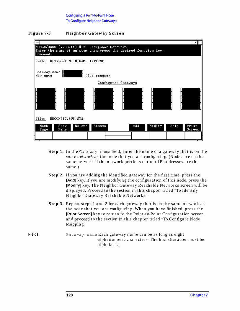
Configuring a Point-to-Point NodeTo Configure Neighbor Gateways
Figure 7-3 Neighbor Gateway Screen
Step 1. In the Gateway name field, enter the name of a gateway that is on thesame network as the node that you are configuring. (Nodes are on thesame network if the network portions of their IP addresses are thesame.).
Step 2. If you are adding the identified gateway for the first time, press the[Add] key. If you are modifying the configuration of this node, press the[Modify] key. The Neighbor Gateway Reachable Networks screen will bedisplayed. Proceed to the section in this chapter titled “To IdentifyNeighbor Gateway Reachable Networks.”
Step 3. Repeat steps 1 and 2 for each gateway that is on the same network asthe node that you are configuring. When you have finished, press the[Prior Screen] key to return to the Point-to-Point Configuration screenand proceed to the section in this chapter titled “To Configure NodeMapping.”
Fields Gateway name Each gateway name can be as long as eightalphanumeric characters. The first character must bealphabetic.
128 Chapter 7
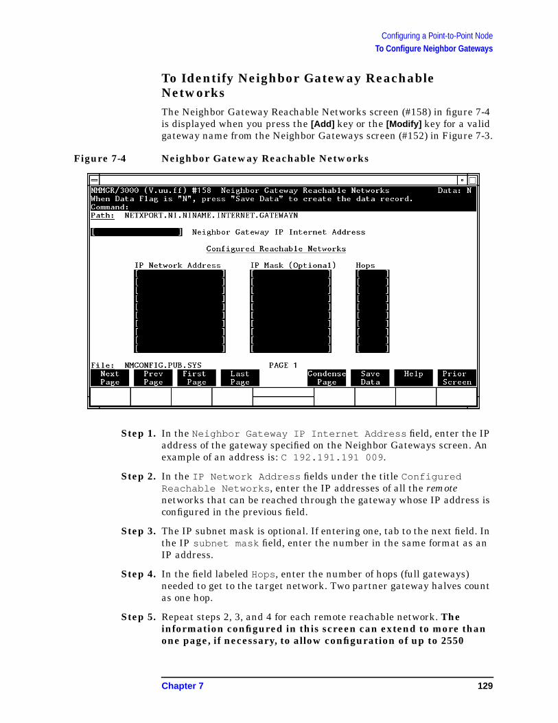
Configuring a Point-to-Point NodeTo Configure Neighbor Gateways
To Identify Neighbor Gateway ReachableNetworksThe Neighbor Gateway Reachable Networks screen (#158) in figure 7-4is displayed when you press the [Add] key or the [Modify] key for a validgateway name from the Neighbor Gateways screen (#152) in Figure 7-3.
Figure 7-4 Neighbor Gateway Reachable Networks
Step 1. In the Neighbor Gateway IP Internet Address field, enter the IPaddress of the gateway specified on the Neighbor Gateways screen. Anexample of an address is: C 192.191.191 009 .
Step 2. In the IP Network Address fields under the title ConfiguredReachable Networks , enter the IP addresses of all the remotenetworks that can be reached through the gateway whose IP address isconfigured in the previous field.
Step 3. The IP subnet mask is optional. If entering one, tab to the next field. Inthe IP subnet mask field, enter the number in the same format as anIP address.
Step 4. In the field labeled Hops, enter the number of hops (full gateways)needed to get to the target network. Two partner gateway halves countas one hop.
Step 5. Repeat steps 2, 3, and 4 for each remote reachable network. Theinformation configured in this screen can extend to more thanone page, if necessary, to allow configuration of up to 2550
Chapter 7 129
Configuring a Point-to-Point NodeTo Configure Neighbor Gateways
reachable networks per link (255 pages and 10 reachable netsper page). If you need to configure more than 10 networks, press the[Save Data] key then press the [Next Page] key to enter more networks.
Step 6. After you have finished entering the IP addresses of all the reachablenetworks, press the [Save Data] key. Press the [Prior Screen] key toreturn to the Neighbor Gateways screen.
Step 7. Back at the Neighbor Gateways screen, after you have finished addingall of the neighboring gateways, press the [Prior Screen] key to return tothe Point-to-Point Link Configuration screen. Proceed to the section inthis chapter titled “To Configure Node Mapping.”
Fields If you have identified any neighbor gateways, then you will also beidentifying: 1) the IP Network Addresses of all of the networks that youcan reach through that gateway, and 2) the number of hops(corresponding to the number of gateways) that a packet passesthrough to reach a remote network from the local network. Twogateway halves count as one hop.
Neighbor GatewayIP InternetAddress The IP address of the gateway whose name you have
specified on the Neighbor Gateways Screen. The IPaddress is in the same format as on the Point-to-PointConfiguration screen.
IP NetworkAddress In the fields under this heading, you list the IP
addresses of all of the networks that you will be able toreach through the gateway you are configuring. Youalso use this field to indicate whether or not thegateway is to serve as a default gateway byentering an at sign (@) to specify that it is adefault gateway. Only one gateway can bedesignated as a default gateway for each900 Series HP 3000 system.
IP Mask(Optional) The fields under this heading allow you to specify a
subnet mask for each reachable network. This mask isoptional. See Chapter 2, “Networking Concepts,” fordetails on deriving the IP mask.
Hops In the fields under this heading, enter the number ofhops corresponding to the number of gateways that apacket travels to reach a remote network from a localnetwork. Note: if you choose SD, no other nodes can beaccessed through the remote host; it is an end point inthe connection. Enter DC if the link is a leased line,private line, or other non-switched link.
130 Chapter 7
Configuring a Point-to-Point NodeTo Configure Node Mapping
To Configure Node MappingThe screens discussed in the following pages allow you to configureshared dial or direct connect and dial node mapping. These screensallow you to specify routes to target (destination) nodes and to indicatethe priority of each route.
The number of mappings you enter depends on how many links are onthe node you are configuring.
Nodes Having Single Links
If you are configuring a node (call it Node A) that has only onePoint-to-Point link to a second node (call it Node B), you enter one routename as the mapping to the adjacent node (Node B).
If there are additional nodes attainable beyond Node B, you would onlyhave to enter one more mapping: make up a route name, and then youcan indicate the additional (non-adjacent) nodes by specifying a“wildcard” (@) in the destination IP address field of either the Dialed orNon-dialed Node Mapping Configuration screens.
Nodes Having Multiple Links
If you are configuring a node that has more than one Point-to-Pointlink, you could ultimately have several paths to a non-adjacentdestination node. Hence, if this node has more than one Point-to-Pointlink, enter a symbolic route name for every other destination node onthe network.
The route name is only used during configuration of this node, and youdo not have to repeat it when you configure other nodes.
To Select a Node Mapping ScreenTo begin configuring node mapping, you should be at the Point-to-PointLink Configuration screen (#44) in Figure 7-2. You will configure nodemapping for each link you are configuring.
Step 1. Enter the name of a configured link in the field at the bottom of thescreen next to the words To configure router mapping enterLink Name .
Step 2. Press the [Link Routing] key.
Step 3. If the Type specified for the selected link is SD, proceed to the section inthis chapter titled “To Configure Shared Dial Node Mapping.”
Step 4. If the Type specified for the selected link is DD or DC, proceed to thesection in this section titled “To Configure Direct Connect/Dial NodeMapping.”
Chapter 7 131

Configuring a Point-to-Point NodeTo Configure Node Mapping
To Configure Shared Dial Node MappingThe Shared Dial Node Mapping Configuration screen (#46) in Figure7-5is displayed if you press the [Link Routing] key at the Point-to-PointLink Configuration screen (#44) for a link of type SD.
Figure 7-5 Shared Dial Node Mapping Configuration Screen
Each router NI can have up to 1024 mappings. However, 4096 is theabsolute maximum number of unique phone numbers supported perNMCONFIG File.
Step 1. In the Route Name field, enter a symbolic name that represents a routebetween the node you are configuring and destination node
Step 2. In the Destination IP Address field, enter the IP address of thedestination node for which a route is being specified.
Step 3. In the Priority field, enter a number from 1 to 99 to indicate thepriority of this route if there are multiple routes to a destination.
Step 4. In the Phone Number field, enter the telephone number of thedestination node. (Leave this field blank if the target node isnon-adjacent.)
Step 5. The Security String field is optional. You may enter a string thatremote nodes must use to gain dial link access to the node you areconfiguring.
Step 6. In the Disable Route field, leave the default alone unless you want totemporarily disable a configured route.
132 Chapter 7
Configuring a Point-to-Point NodeTo Configure Node Mapping
Step 7. Press the [Save Data] key to save the data on the screen. Proceed toChapter 10, “Validating Network Transport and Cross-Validating withSYSGEN,” and press the [Validate Netxport] key.
Optional KeysPress the [Next Link] key to call up another link whenyou want to configure information about its adjacentand non-adjacent nodes.
Press the [Config Directry] key to configure the NetworkDirectory screen.
Fields Route Name A symbolic name, up to eight alphanumeric characters,that represents a route between the node you areconfiguring and a destination node. The route name isonly used within the NMMGR program. It is mostuseful when the node you are configuring has morethan one possible way of accessing a target(destination) node. It identifies different routes totarget nodes and is not the actual target node name. Itis used because you may need a way to identify morethan one route to a target node. There should be atlease one symbolic route name for routes to every otherdestination node on the network unless you use the “@”wildcard destination IP address.
To help keep track of routes, you can use thedestination node name as the route name. If you havemore than one route to a given node, you can name theroutes nodename1, nodename2, and so forth.
DestinationIP Address IP address of the target (destination) node for which a
route is being defined.
Priority Number from 1 to 99 that indicates which route hasprecedence (priority) over another when there aremultiple routes to a destination. A route to adestination that has a higher priority will takeprecedence over a route with a lower priority. This fieldis the primary means of influencing the choice of route.
Phone Number Required if the link is a dial link. The field must beblank if the target node is non-adjacent. Enter thetelephone number as a combination of decimal numbers(0 through 9), dashes, and the following specialcharacters:
/ Separator used for automatic call unitsthat have second dial-tone detect.
E Optional end-of-number indicator.
Chapter 7 133

Configuring a Point-to-Point NodeTo Configure Node Mapping
D Three-second delay (used for Europeanmodems and automatic call units thatrequire built-in delays).
# Defined by local phone system.
* Defined by local phone system.
To disable outbound dialing, enter an exclamation point(! ) by itself in the phone number field.
Each router NI can have up to 1024 mappings.However, 4096 is the absolute maximum number ofunique phone numbers supported per NMCONFIG File.
SecurityString An optional security string that remote nodes must use
to gain dial link access to the node. It can be up to eightalphanumeric characters, left justified, with noembedded blanks. The first character must bealphabetic.
Disable RouteY (yes) or N (no) indicator that allows you to temporarilydisable a configured route. Leave the default (N) alone ifyou do not want to disable the route.
To Configure Direct Connect/Dial Node MappingThe Direct Connect/Dial Node Mapping Configuration screen (#45) inFigure 7-6 is displayed if you press the [Link Routing] key at thePoint-to-Point Link Configuration screen (#44) for a link of type DD orDC.
134 Chapter 7
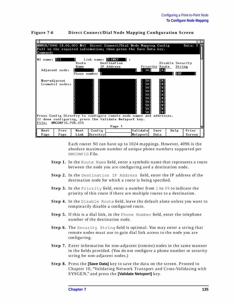
Configuring a Point-to-Point NodeTo Configure Node Mapping
Figure 7-6 Direct Connect/Dial Node Mapping Configuration Screen
Each router NI can have up to 1024 mappings. However, 4096 is theabsolute maximum number of unique phone numbers supported perNMCONFIG File.
Step 1. In the Route Name field, enter a symbolic name that represents a routebetween the node you are configuring and a destination node.
Step 2. In the Destination IP Address field, enter the IP address of thedestination node for which a route is being specified.
Step 3. In the Priority field, enter a number from 1 to 99 to indicate thepriority of this route if there are multiple routes to a destination.
Step 4. In the Disable Route field, leave the default alone unless you want totemporarily disable a configured route.
Step 5. If this is a dial link, in the Phone Number field, enter the telephonenumber of the destination node.
Step 6. The Security String field is optional. You may enter a string thatremote nodes must use to gain dial link access to the node you areconfiguring.
Step 7. Enter information for non-adjacent (remote) nodes in the same mannerin the fields provided. (You do not configure a phone number or securitystring for non-adjacent nodes.)
Step 8. Press the [Save Data] key to save the data on the screen. Proceed toChapter 10, “Validating Network Transport and Cross-Validating withSYSGEN,” and press the [Validate Netxport] key.
Chapter 7 135
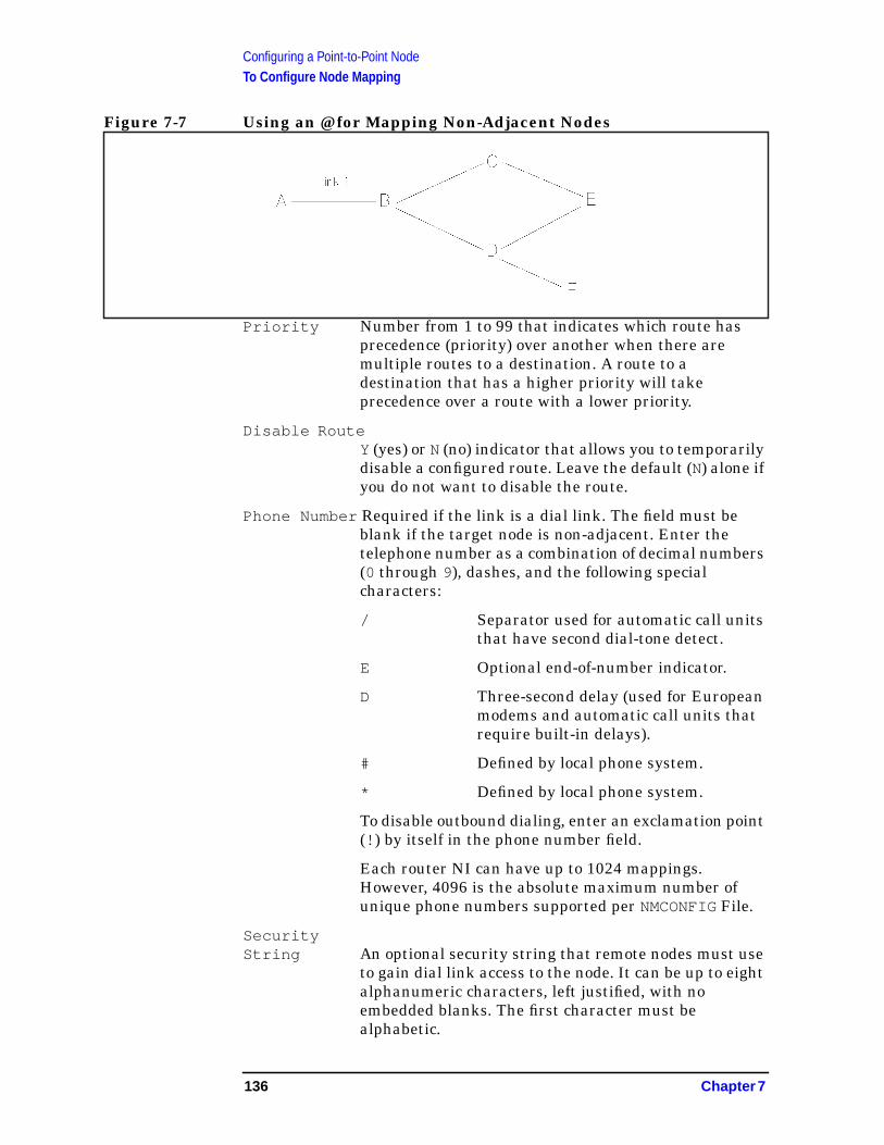
Configuring a Point-to-Point NodeTo Configure Node Mapping
Figure 7-7 Using an @ for Mapping Non-Adjacent Nodes
Priority Number from 1 to 99 that indicates which route hasprecedence (priority) over another when there aremultiple routes to a destination. A route to adestination that has a higher priority will takeprecedence over a route with a lower priority.
Disable RouteY (yes) or N (no) indicator that allows you to temporarilydisable a configured route. Leave the default (N) alone ifyou do not want to disable the route.
Phone Number Required if the link is a dial link. The field must beblank if the target node is non-adjacent. Enter thetelephone number as a combination of decimal numbers(0 through 9), dashes, and the following specialcharacters:
/ Separator used for automatic call unitsthat have second dial-tone detect.
E Optional end-of-number indicator.
D Three-second delay (used for Europeanmodems and automatic call units thatrequire built-in delays).
# Defined by local phone system.
* Defined by local phone system.
To disable outbound dialing, enter an exclamation point(! ) by itself in the phone number field.
Each router NI can have up to 1024 mappings.However, 4096 is the absolute maximum number ofunique phone numbers supported per NMCONFIG File.
SecurityString An optional security string that remote nodes must use
to gain dial link access to the node. It can be up to eightalphanumeric characters, left justified, with noembedded blanks. The first character must bealphabetic.
136 Chapter 7
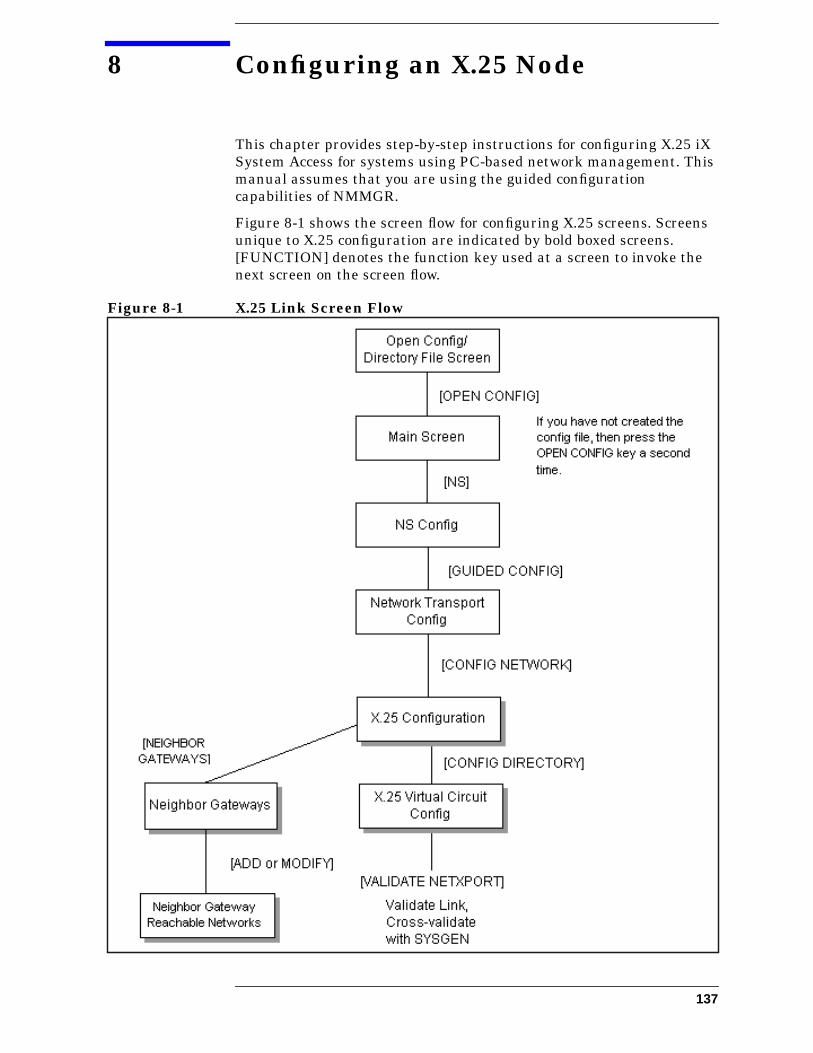
8 Configuring an X.25 Node
This chapter provides step-by-step instructions for configuring X.25 iXSystem Access for systems using PC-based network management. Thismanual assumes that you are using the guided configurationcapabilities of NMMGR.
Figure 8-1 shows the screen flow for configuring X.25 screens. Screensunique to X.25 configuration are indicated by bold boxed screens.[FUNCTION] denotes the function key used at a screen to invoke thenext screen on the screen flow.
Figure 8-1 X.25 Link Screen Flow
137

Configuring an X.25 Node
Before using NMMGR to configure a link, you should complete theworksheets provided. See Chapter 4, “Planning for NodeConfiguration,” for more information on planning your configurationand filling out the configuration worksheets.
This chapter includes step-by-step instructions to help you perform thefollowing tasks:
• Begin the configuration process.
• Configure an X.25 network interface.
• Configure neighbor gateways.
Once the above tasks are completed, refer to Chapter 10, “ValidatingNetwork Transport and Cross-Validating with SYSGEN,” forstep-by-step instructions to help you perform the following validationtasks:
• Validate the network transport configuration.
• Cross-validate in SYSGEN.
NOTE If you are configuring X.25 iX System Access on a system that is usinghost-based network management (a PC running the HP OpenViewNetwork Manager is not part of the network), use Configuring andManaging Host-Based X.25 Links instead of this manual forstep-by-step configuration instructions.
138 Chapter 8

Configuring an X.25 NodeTo Configure an X.25 Network Interface
To Configure an X.25 Network InterfaceThe X.25 Configuration screen (#48) in Figure 8-2 is displayed whenyou press the [Config Network] key at the Network TransportConfiguration screen (#42) with an NI type of 3 (X.25). Refer to Chapter5, “Introductory Screens,” for information on the Network TransportConfiguration screen.
Figure 8-2 NS Configuration Screen
Step 1. In the IP address field, enter the internet protocol (IP) address for thenode being configured. An example of an address is:C 192.191.191 009 .
Step 2. The IP subnet mask is optional. If entering one, tab to the IP subnetmask field and enter the number in the same format as an IP address.
Step 3. Move to the first Link name field. Enter a link name to represent theDTC/X.25 Network Access card for which you are configuring a link.This name must be unique to both the node and the DTC. It must alsobe the same as the link name configured for this card when theDatacommunications and Terminal Subsystem (DTS) was configured.
Step 4. Enter the node name of the DTC that houses the DTC/X.25 Access cardin the first DTC Node Namefield then enter the slot number of the cardin the Card Number field. Enter a link name, DTC node name, andcard number for each link you are configuring.
Chapter 8 139
Configuring an X.25 NodeTo Configure an X.25 Network Interface
Step 5. When you are done adding links, press the [Save Data] key.
Step 6. If the network that this node is on contains ANY internetwork gateway(either full or half) press the [Neighbor Gateways] key and proceed to thesection in this chapter called “To Configure Neighbor Gateways.”
Step 7. If the network that this node is on contains NO internetwork gatewaysor if you have already configured gateways for this system, press the[Config Directry] key and proceed to the section in this chapter titled “ToConfigure X.25 Virtual Circuits.”
Optional KeysPress the [List NIs] key to list the names and types ofalready configured network interfaces.
Press the [Delete NI] key to remove a configured networkinterface from the configuration file.
Press the [Read Other NI] key to call up a previouslyconfigured Network Interface name.
Fields Node Name Display only.
NetworkInterface(NI) name Display only.
IP address IP address is an address of a node on a network. An IPaddress has two parts: a network portion and a nodeportion. The network portion must be the same for allnodes on an X.25 network; the node portion must beunique for all nodes on an X.25 network.
There are two methods of entering an internet protocol(IP) address within NMMGR:
1. Enter the fully qualified IP address (for example,Class C, C 192.191.191 009 ).
OR
2. Enter only the network (nnn) and node (xxx)portions of the IP address as four positive integersbetween 0 and 255 separated by periods or blanks(for example, 15.123.44.98 ).
You need not enter the following items as NMMGRwill fill these in:
• Class A, B, C
• Leading zeros for the network and node portion ofthe IP address.
140 Chapter 8
Configuring an X.25 NodeTo Configure an X.25 Network Interface
HP assigns the network portion (initial nine digits) ofIP addresses from ARPA Class C, though youraddresses may also be of Classes A or B. The completeformats are:
For Class C, the node portion of the IP address must bebetween 001 and 254 .
If you are adding your NS 3000/iX node to an existingnetwork, the network portion of each node’s IP addressshould be the same. You will have to find out what thisis, and use it in the network portion of the IP address ofyour NS 3000/iX node. Also, you will need to know thenode portions of the IP addresses of each of the nodes(usually they will be numbered sequentially, such as001 , 002 , and so on), so that you can specify a uniquenode portion for the IP address of your node. If youhave a network map, it should provide a record of suchitems as the node name and IP address of each node. Ifthere is no record, and if you want to find out eachnode’s IP address, you will have to issue the followingcommand (NM capability required) on each of thenodes:
NETCONTROL NET=NIname;STATUS
One of the lines of output from this command tells youwhat the complete IP address is for that node; the lastthree digits are the unique node portion of the class Caddress.
NOTE To obtain a class B or C IP address, contact Government Systems,Incorporated (GSI). To obtain an application form, write GSI at theaddress below. Allow at least eight working days for GSI to process anIP address request.
Government Systems, Inc.Attn: Network Information Center7990 Boeing Ct.Vienna, VA 22183(800) 364-3642 (703) 821-6161
Class A nnn xxx.xxx.xxx
B nnn.nnn xxx.xxx
C nnn.mmm.mmm xxx
Where: nnn = the network portion of the IP address andxxx = the node portion of the IP address.
Chapter 8 141

Configuring an X.25 NodeTo Configure an X.25 Network Interface
IP subnetmask An IP subnet mask is specified in the same format as
an IP address. The 32-bit mask is grouped in octetsexpressed as decimal integers and delimited by either aperiod (.) or a space. An IP mask is used whenconfiguring subnetworks. The mask identifies whichbits of an IP address will be used to define asubnetwork. To determine these bits, you first need toestimate how many subnetworks and nodes persubnetwork you need. See Chapter 2, “NetworkingConcepts,” for details on deriving an IP subnet mask.
Link name The link name identifies a specific DTC/X.25 NetworkAccess card to be used for X.25 system-to-systemconnections. This link name must be the same as thelink name you entered for this card when youconfigured your DTCs. You may configure up to 11links. (One link must be used for loopback. Loopbackwill be automatically configured during the guidedscreen configuration.)
DTC NodeName The DTC node name is the fully qualified nodename
(name.domain.organization ) of the DTC thatcontains the DTC/X.25 Network Access card with theconfigured link name.
Card Number The DTC card number is the number of the DTC/X.25Network Access card in the associated DTC. If the cardis contained in a DTC 48, the DTC card number can beany number from 1 to 5. If the card is contained in aDTC 16, the card number must be 2.
To Configure X.25 Virtual CircuitsThe X.25 Virtual Circuit Configuration screen (#47) in Figure 8-3 isdisplayed if you press the [Config Directry] key from the X.25Configuration screen (#48) in Figure 8-2. This screen lets you configurethe network directory.
142 Chapter 8
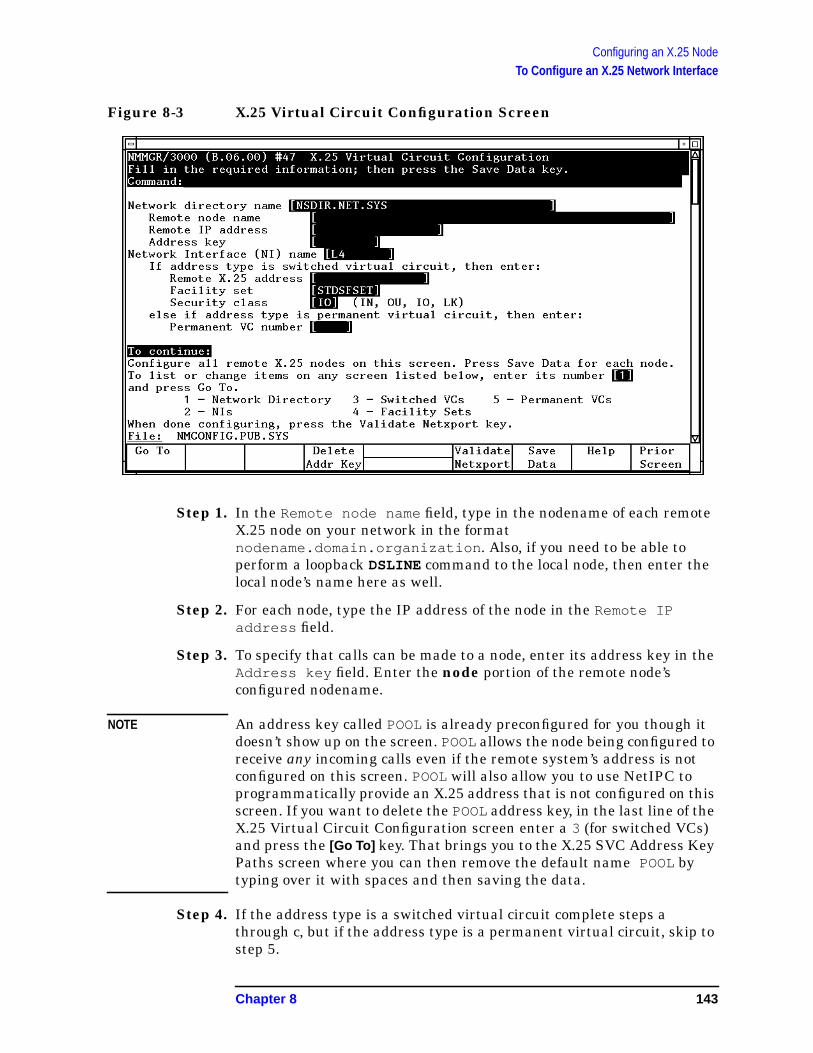
Configuring an X.25 NodeTo Configure an X.25 Network Interface
Figure 8-3 X.25 Virtual Circuit Configuration Screen
Step 1. In the Remote node name field, type in the nodename of each remoteX.25 node on your network in the formatnodename.domain.organization . Also, if you need to be able toperform a loopback DSLINE command to the local node, then enter thelocal node’s name here as well.
Step 2. For each node, type the IP address of the node in the Remote IPaddress field.
Step 3. To specify that calls can be made to a node, enter its address key in theAddress key field. Enter the node portion of the remote node’sconfigured nodename.
NOTE An address key called POOL is already preconfigured for you though itdoesn’t show up on the screen. POOLallows the node being configured toreceive any incoming calls even if the remote system’s address is notconfigured on this screen. POOL will also allow you to use NetIPC toprogrammatically provide an X.25 address that is not configured on thisscreen. If you want to delete the POOLaddress key, in the last line of theX.25 Virtual Circuit Configuration screen enter a 3 (for switched VCs)and press the [Go To] key. That brings you to the X.25 SVC Address KeyPaths screen where you can then remove the default name POOL bytyping over it with spaces and then saving the data.
Step 4. If the address type is a switched virtual circuit complete steps athrough c, but if the address type is a permanent virtual circuit, skip tostep 5.
Chapter 8 143
Configuring an X.25 NodeTo Configure an X.25 Network Interface
a. In the Remote X.25 address field, enter the X.25 address of theremote host for X.25 public data networks or private networks.
b. Make sure the name of the facility set you are using is in theFacility set field. You may either choose the default facility set(STDSFSET) or enter an alternative. If you are configuring a newfacility set, enter a new name. (To modify facility set parameters,enter a 5 in the last field on the screen and press the [Go To] key.)
c. In the Security class field, enter the level of logical security youwant to have on this particular entry. The possible values are IN(accept calls from the address), IO (accept calls from and send callsto the address, default), OU(send calls to the address, incoming callsare rejected), and LK (block calls to or from the address).
Step 5. If the address type is a permanent virtual circuit (PVC), in thePermanent VC number field, enter the PVC number of the PVC on theremote node. This value cannot be greater than the number of PVCs forwhich you are subscribed. It must be within the PVC range you definedduring DTC configuration.
Step 6. After you have finished entering new information for each remote node,press the [Save Data] key. (Press the key once for each remote node youare configuring.)
Step 7. If you have completed configuration of X.25, press the [Validate Netxport]key and proceed to Chapter 10, “Validating Network Transport andCross-Validating with SYSGEN.” Otherwise, press the [Prior Screen]key to return to the X.25 Configuration screen.
Fields Networkdirectoryname The network directory file that will be updated by the
information entered through this screen.
Remote nodename You must enter the remote node name of each X.25
node into the network directory. Include entries for allremote nodes and, if you want to be able to performloopback, the local node as well.
Remote IPaddress Also in the network directory, you must enter the IP
Address of each node whose identity you have enteredinto the network directory. For the format of thisparameter, see the information in the “Fields” sectionunder “Configure X.25 Network.”
Address key The X.25 address key is the name of a remote node withwhich your local node will be communicating.Hewlett-Packard recommends that you make the namebe the node portion of the remote node’s name (whereits full name is node.domain.organization ). You
144 Chapter 8
Configuring an X.25 NodeTo Configure an X.25 Network Interface
must configure an X.25 address key for each remotenode with which your node will be communicating. Youhave a combined maximum of 1024 X.25 address keysin the SVC and PVC path tables. The X.25 address keyname must be eight characters or less and the firstcharacter must be alphabetic. A default address keycalled POOL allows any system to access the localsystem even if the remote system’s address is notconfigured. POOL can also be used when level 3programmatic access (NetIPC) provides an X.25address.
NetworkInterface(NI) name Display only.
SVC or PVCParameters The parameters for assigning either SVCs or PVCs are
described in the following paragraphs.
For SVCs Remote X.25address The remote X.25 address is the remote node’s X.25
address. This address is required for SVCs if you havespecified an X.25 address key. This address must be15 digits or less.
Facility set The facility set name is a name for a set of X.25connection parameters. The parameters are determinedby the type of X.25 network that you are subscribed to.You can configure options in a facility set so thatspecified options are available for every virtual circuitor negotiated for each virtual circuit on a per-call basis.This facility set will be used when a connection is madefrom your node to the specified remote node or from thespecified remote node to your node. A Facility Set isrequired for SVCs if you have specified an X.25 AddressKey. The facility set name must be eight characters orless, and the first character must be alphabetic. You canconfigure up to 128 facility sets.
To modify facility set parameters, enter a 5 in the fieldat the bottom of the screen and press the [Go To] key.This will take you to the X.25 User Facility Sets screen.From this screen you can create new or modify existinguser facility sets. See the NS 3000/iX ScreensReference Manual for more information.
Chapter 8 145
Configuring an X.25 NodeTo Configure an X.25 Network Interface
Securityclass The security class is the level of logical security you
want to have when a connection is made to or from thespecified remote node. A Security level is required forSVCs if you have specified an X.25 Address Key. Thepossible values are as follows:
• IO —Both incoming and outgoing calls are accepted.This is the default value.
• IN —Only incoming calls are accepted from thisparticular remote address. Outgoing calls will berejected.
• OU—Only outgoing calls are accepted to thisparticular remote address. Incoming calls will berejected.
• LK—Entry is locked. No call is accepted, eitherinbound or outbound.
For PVCs Permanent VCnumber The PVC Number identifies a permanent virtual circuit
(PVC) on the remote node. If you have entered a namein the X.25 Address Key field and are configuring PVCs,then you also have to enter a value for the PVCNumber.
146 Chapter 8

Configuring an X.25 NodeTo Configure Neighbor Gateways
To Configure Neighbor GatewaysYou need to visit the next two screens only if you are configuring anon-gateway node that is on the same network as a gateway. In thiscase, the non-gateway node needs to know the identity of any neighborgateway. Neighbor gateways can be either full or half gateways.
Gateways that are on the same network are called neighborgateways. A non-gateway node on an X.25 network may need to gothrough a neighbor gateway in order to send messages to an entirelydifferent network. (Two nodes are on the same network if the networkportion of their IP addresses are the same.) All X.25 nodes that are onthe same network as a neighbor gateway need to know the identity ofany neighbor gateways. When you configure an X.25 node, you enterinto its configuration the identity of any accessible neighbor gatewaysthat share the same network. The identified gateways may be eitherfull or half gateways.
You may designate gateways as default gateways. Messages for anetwork will be routed to a default gateway if there is no gatewayconfigured for the destination network. The default gateway will thenattempt to locate the destination of the message.
To Identify Neighbor Gateways (If Any ArePresent)The Neighbor Gateways screen (#152) in Figure 8-4is displayed whenyou press the [Neighbor Gateways] key at the X.25 Configuration screen(#48) in Figure 8-2.
Chapter 8 147
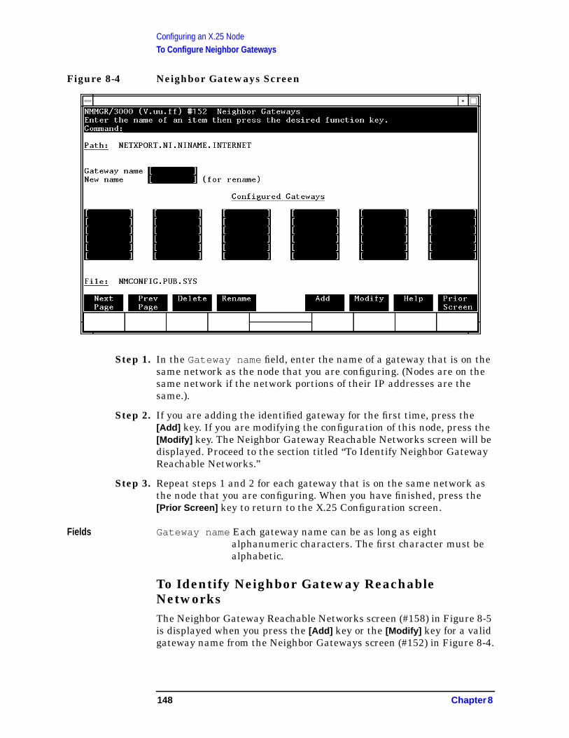
Configuring an X.25 NodeTo Configure Neighbor Gateways
Figure 8-4 Neighbor Gateways Screen
Step 1. In the Gateway name field, enter the name of a gateway that is on thesame network as the node that you are configuring. (Nodes are on thesame network if the network portions of their IP addresses are thesame.).
Step 2. If you are adding the identified gateway for the first time, press the[Add] key. If you are modifying the configuration of this node, press the[Modify] key. The Neighbor Gateway Reachable Networks screen will bedisplayed. Proceed to the section titled “To Identify Neighbor GatewayReachable Networks.”
Step 3. Repeat steps 1 and 2 for each gateway that is on the same network asthe node that you are configuring. When you have finished, press the[Prior Screen] key to return to the X.25 Configuration screen.
Fields Gateway name Each gateway name can be as long as eightalphanumeric characters. The first character must bealphabetic.
To Identify Neighbor Gateway ReachableNetworksThe Neighbor Gateway Reachable Networks screen (#158) in Figure 8-5is displayed when you press the [Add] key or the [Modify] key for a validgateway name from the Neighbor Gateways screen (#152) in Figure 8-4.
148 Chapter 8
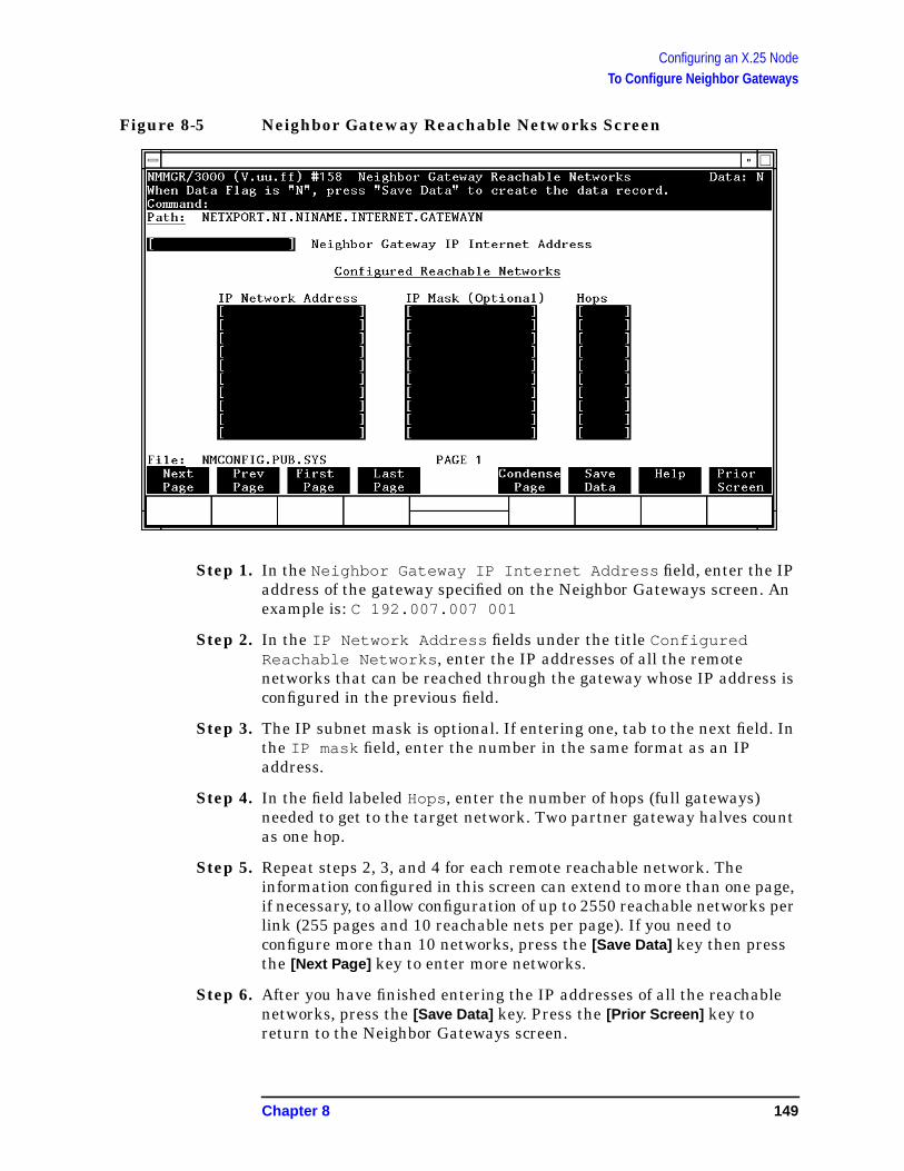
Configuring an X.25 NodeTo Configure Neighbor Gateways
Figure 8-5 Neighbor Gateway Reachable Networks Screen
Step 1. In the Neighbor Gateway IP Internet Address field, enter the IPaddress of the gateway specified on the Neighbor Gateways screen. Anexample is: C 192.007.007 001
Step 2. In the IP Network Address fields under the title ConfiguredReachable Networks , enter the IP addresses of all the remotenetworks that can be reached through the gateway whose IP address isconfigured in the previous field.
Step 3. The IP subnet mask is optional. If entering one, tab to the next field. Inthe IP mask field, enter the number in the same format as an IPaddress.
Step 4. In the field labeled Hops, enter the number of hops (full gateways)needed to get to the target network. Two partner gateway halves countas one hop.
Step 5. Repeat steps 2, 3, and 4 for each remote reachable network. Theinformation configured in this screen can extend to more than one page,if necessary, to allow configuration of up to 2550 reachable networks perlink (255 pages and 10 reachable nets per page). If you need toconfigure more than 10 networks, press the [Save Data] key then pressthe [Next Page] key to enter more networks.
Step 6. After you have finished entering the IP addresses of all the reachablenetworks, press the [Save Data] key. Press the [Prior Screen] key toreturn to the Neighbor Gateways screen.
Chapter 8 149
Configuring an X.25 NodeTo Configure Neighbor Gateways
Step 7. Back at the Neighbor Gateways screen, after you have finished addingall of the neighboring gateways, press the [Prior Screen] key to return tothe X.25 Configuration screen. Follow the instructions for step 7 in thesection in this chapter titled “To Configure an X.25 Network.”
Fields If you have identified any neighbor gateways, then you will also beidentifying: 1) the IP Network Addresses of all of the networks that youcan reach through that gateway, and 2) the number of hops(corresponding to the number of gateways) that a packet passesthrough to reach a remote network from the local network. Twogateway halves count as one hop.
Neighbor GatewayIP InternetAddress The IP address of the gateway whose name you have
specified on the Neighbor Gateways Screen. The IPaddress is in the same format as the LANConfiguration screen.
IP NetworkAddress In the fields under this heading, you list the IP
addresses of all of the networks that you will be able toreach through the gateway you are configuring. Youalso use this field to indicate whether or not thegateway is to serve as a default gateway by entering anat sign (@) to specify that it is a default gateway. Onlyone gateway can be designated as a default gateway foreach HP 3000 Series 900 system.
IP Mask(Optional) The fields under this heading allow you to specify a
subnet mask for each reachable network. This mask isoptional. For details on deriving an IP subnet mask, seeChapter 2, “Networking Concepts.”
Hops In the fields under this heading, enter the number ofhops corresponding to the number of gateways that apacket travels to reach a remote network from a localnetwork.
150 Chapter 8
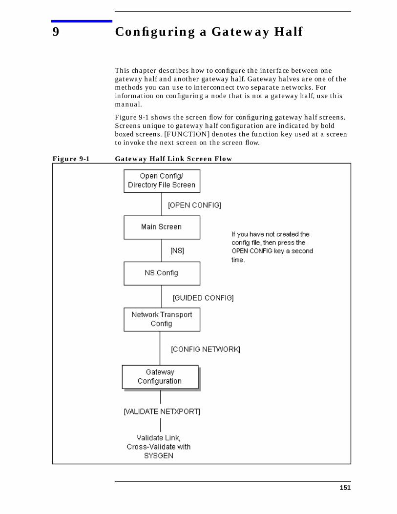
9 Configuring a Gateway Half
This chapter describes how to configure the interface between onegateway half and another gateway half. Gateway halves are one of themethods you can use to interconnect two separate networks. Forinformation on configuring a node that is not a gateway half, use thismanual.
Figure 9-1 shows the screen flow for configuring gateway half screens.Screens unique to gateway half configuration are indicated by boldboxed screens. [FUNCTION] denotes the function key used at a screento invoke the next screen on the screen flow.
Figure 9-1 Gateway Half Link Screen Flow
151
Configuring a Gateway Half
Configuring a node as a gateway half requires configuring two separatenetwork interfaces: one for the interface between the two gatewayhalves, and a second for the gateway half ’s interface to its homenetwork.
If this gateway half interfaces to a LAN, Token Ring, FDDI,100VG-AnyLAN, or 100Base-T network, you should have alreadyconfigured its network interface according to the instructions inChapter 6, “Configuring a LAN, Token Ring, FDDI, 100VG-AnyLAN,100Base-T Node.” If this gateway half interfaces to a Point-to-Point orX.25 network, you should already have configured its NI according toinstructions in Chapter 7, “Configuring a Point-to-Point Node,” andChapter 8, “Configuring an X.25 Node,” respectively. If you have not, doso now and then return to this chapter.
This chapter includes step-by-step instructions to help you perform thefollowing tasks:
• Begin the configuration process.
• Configure a gatehalf.
Once the above tasks are completed, refer to Chapter 10, “ValidatingNetwork Transport and Cross-Validating with SYSGEN,” forstep-by-step instructions to help you perform the following validationtasks:
• Validate the network transport configuration.
• Cross-validate in SYSGEN.
152 Chapter 9
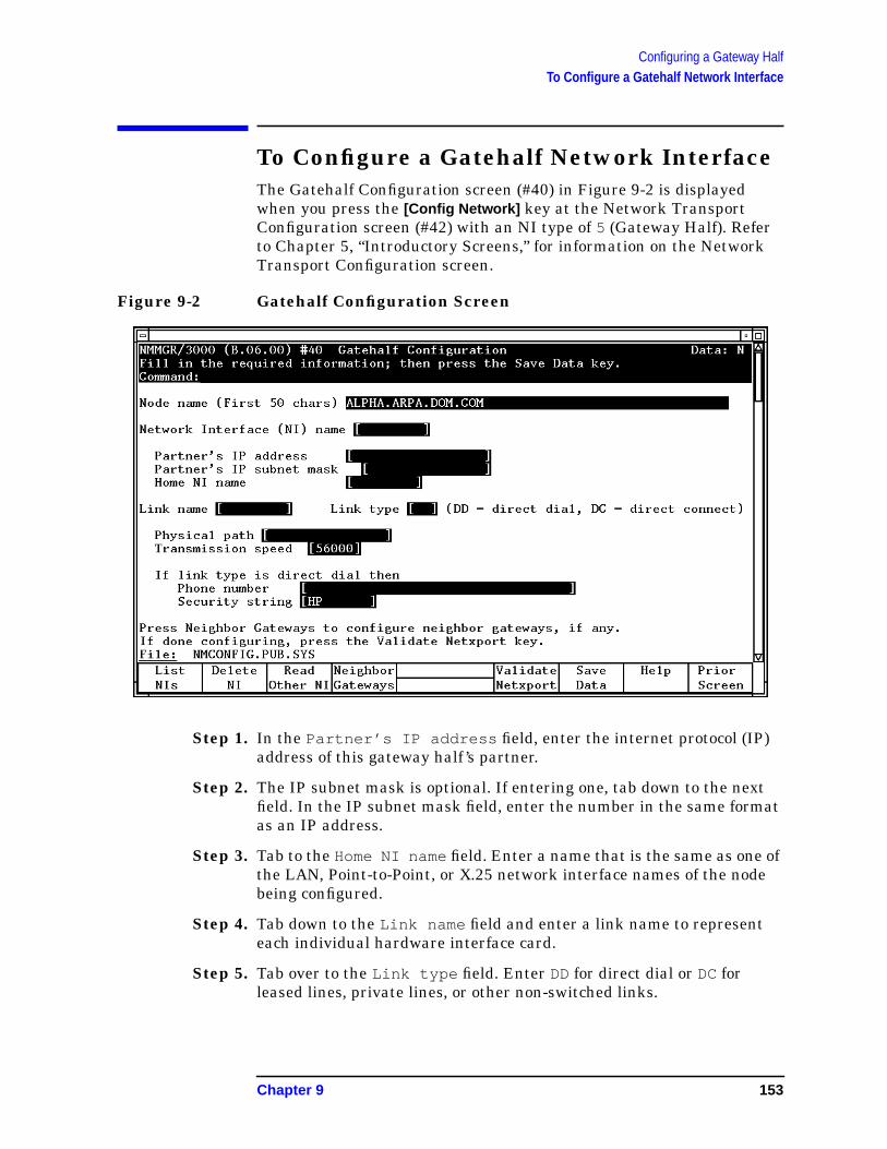
Configuring a Gateway HalfTo Configure a Gatehalf Network Interface
To Configure a Gatehalf Network InterfaceThe Gatehalf Configuration screen (#40) in Figure 9-2 is displayedwhen you press the [Config Network] key at the Network TransportConfiguration screen (#42) with an NI type of 5 (Gateway Half). Referto Chapter 5, “Introductory Screens,” for information on the NetworkTransport Configuration screen.
Figure 9-2 Gatehalf Configuration Screen
Step 1. In the Partner’s IP address field, enter the internet protocol (IP)address of this gateway half ’s partner.
Step 2. The IP subnet mask is optional. If entering one, tab down to the nextfield. In the IP subnet mask field, enter the number in the same formatas an IP address.
Step 3. Tab to the Home NI namefield. Enter a name that is the same as one ofthe LAN, Point-to-Point, or X.25 network interface names of the nodebeing configured.
Step 4. Tab down to the Link name field and enter a link name to representeach individual hardware interface card.
Step 5. Tab over to the Link type field. Enter DD for direct dial or DC forleased lines, private lines, or other non-switched links.
Chapter 9 153
Configuring a Gateway HalfTo Configure a Gatehalf Network Interface
Step 6. Enter the physical path of this node’s Programmable Serial Interface(PSI) card.
Step 7. Tab down to the next field. In the Transmission speed field, eitherleave the default or enter the transmission speed in bits per second as anumber from 1200 to 64000.
Step 8. If this is a dial link, enter the phone number of this gateway half ’spartner.
Step 9. If this is a dial link, in the Security string field, either leave thedefault, or enter a value that HP nodes must use to gain dial link accessto the node you are configuring.
Step 10. Press the [Save Data] key. Proceed to Chapter 10, “Validating NetworkTransport and Cross-Validating with SYSGEN,” and press the[Validate Netxport] key.
Optional KeysPress the [List NIs] key to list the names and types ofalready configured network interfaces.
Press the [Delete NI] to remove a configured networkinterface from the configuration file.
Press the [Read Other NI] key to call up a previouslyconfigured Network Interface name.
Fields Partner’s IPaddress This is the internet protocol (IP) address of the node
that will be the other half of the gateway half you areconfiguring. Enter the address in the same format as onthe Point-to-Point Configuration screen.
Partner’s IPsubnet mask Allows you to specify the subnet mask of this gateway
half ’s partner gateway half. The 32-bit mask is groupedin octets expressed as decimal integers and delimitedby either a period (.) or a space. The mask identifieswhich bits of an IP address will be used to define asubnetwork. To determine these bits, you first need toestimate how many subnetworks and nodes persubnetwork you need. For details on deriving an IPsubnet mask, see Chapter 2, “Networking Concepts.”
Home NI name The home NI name will be used by the software todetermine which network address is the sourcenetwork address when packets are sent over thegateway half. The home NI name cannot be either agateway half or loopback NI name, but it can refer toany other type of network interface (LAN, Token Ring,Point-to-Point, or X.25 network interface).
154 Chapter 9
Configuring a Gateway HalfTo Configure a Gatehalf Network Interface
Link name Name that represents the hardware link. The linkname can have up to eight alphanumeric characters;the first character must be alphabetic. The link namemust be unique to both the node and the network.
Link type The link type for a gateway half can be either DD fordirect dial or DC for direct connect.
physical pathThe physical path of the gateway half ’s PSI card. SeeChapter 8, “Configuring an X.25 Node,” for informationon the physical path.
Transmissionspeed The line transmission speed is given in bits per second.
For direct connect the value, must be supported by thecable. Values are 1200, 2400, 4800, 9600, 19200, 38400,56000, and 64000. The default is 56000.
Phone Number Telephone number of this gateway half ’s partnergateway half. Enter the telephone number as acombination of decimal numbers (0 through 9), dashes,and the following special characters:
/ Separator used for automatic call unitsthat have second dial-tone detect.
E Optional end-of-number indicator.
D Three-second delay (used for Europeanmodems and automatic call units thatrequire built-in delays).
# Defined by local phone system.
* Defined by local phone system.
Spaces, and left and right parentheses ( ) are alsoallowed.
To disable outbound dialing, enter an exclamation point(! ) by itself in the phone number field.
Securitystring This is a string containing up to eight alphanumeric
characters, left justified, with no embedded blanks. Thefirst character must be alphabetic. A value in this fieldis required if the remote (destination) node is an HPnode (dial ID protocol is used). Remote HP nodes mustuse the security string to gain dial link access to thenode you are configuring.
Chapter 9 155

Configuring a Gateway HalfTo Configure a Gatehalf Network Interface
156 Chapter 9
10 Validating Network Transport andCross-Validating with SYSGEN
This chapter discusses the validation of the network transportconfiguration and cross-validation of NMCONFIG.PUB.SYS with thesystem configuration files within SYSGEN.
Validating the network transport. This step checks data consistencybetween values entered on different NMMGR data entry screens.Cross-Validating with SYSGEN.
Cross-validation ensures that there are no conflicts in the use of nodenames, device classes, and physical paths.
157
Validating Network Transport and Cross-Validating with SYSGENTo Validate the Network Transport
To Validate the Network TransportThe following procedure assumes that you have already configured andvalidated the Distributed Terminal Subsystem (DTS). The DTS must bevalidated before you can validate the network transport (Netxport)software. Upon configuring the selected screens for your network:
Step 1. Press the [Validate Netxport] key. Refer to the list of screens with the[Validate Netxport] key.
LAN — Figure 6-2Token Ring — Figure 6-3FDDI — Figure 6-4100VG-AnyLAN — Figure 6-5100Base-T — Figure 6-6Point-to-Point Shared Dial — Figure 7-5Point-to-Point Direct Dial — Figure 7-6X.25 — Figure 8-3Gateway Half — Figure 9-2Logging — Figure 13-2
Messages similar to the following ones will be displayed:
Searching for subsystem validation routine VALIDATENETXPOR–> VALIDATION OF NETXPORT SUBSYSTEM STARTED–> VALIDATION OF NETXPORT SUBSYSTEM FINISHEDCopying validated subsystems to backup configurationfile (Press RETURN when done viewing screen contents)
Step 2. See the NS 3000/iX Error Messages Reference Manual for explanationsof any validation errors. After viewing the messages, press [RETURN] toreturn to the LAN, Token Ring, FDDI, 100VG-AnyLAN, and 100Base-TConfiguration screen.
Step 3. If you need to configure a network directory, proceed to Chapter 11,“Configuring the Network Directory.” If you do not need to configure thenetwork directory, exit NMMGR, and proceed to the section in thischapter titled “To Cross-Validate in SYSGEN.” To exit NMMGR, pressthe [Prior Screen] key on successive screens until you reach the OpenConfiguration Directory File screen where you should press the[Exit Program] key.
158 Chapter 10

Validating Network Transport and Cross-Validating with SYSGENTo Cross-Validate in SYSGEN
To Cross-Validate in SYSGENCross-validation ensures that there are no conflicts in the use of nodenames, device classes, and physical paths between the data currentlycontained in NMCONFIG.PUB.SYS and the system configuration data.To cross-validate, use the SYSGEN facility (OP capability is required).To use SYSGEN, type the following commands at the MPE prompt(user input is bold):
sysgen sysgen> io
io> ld (optional)
io> exit
sysgen> exit
The optional ld (list devices) command allows you to verify theNMMGR devices that are configured.
Cross-validation is done on the KEEP, TAPE, I/O , and RDCC commandsin SYSGEN. For more information, see System Startup, Configuration,and Shutdown.
If you have completed the configuration process, proceed to Chapter 14,“Operating the Network.”
Chapter 10 159

Validating Network Transport and Cross-Validating with SYSGENTo Cross-Validate in SYSGEN
160 Chapter 10
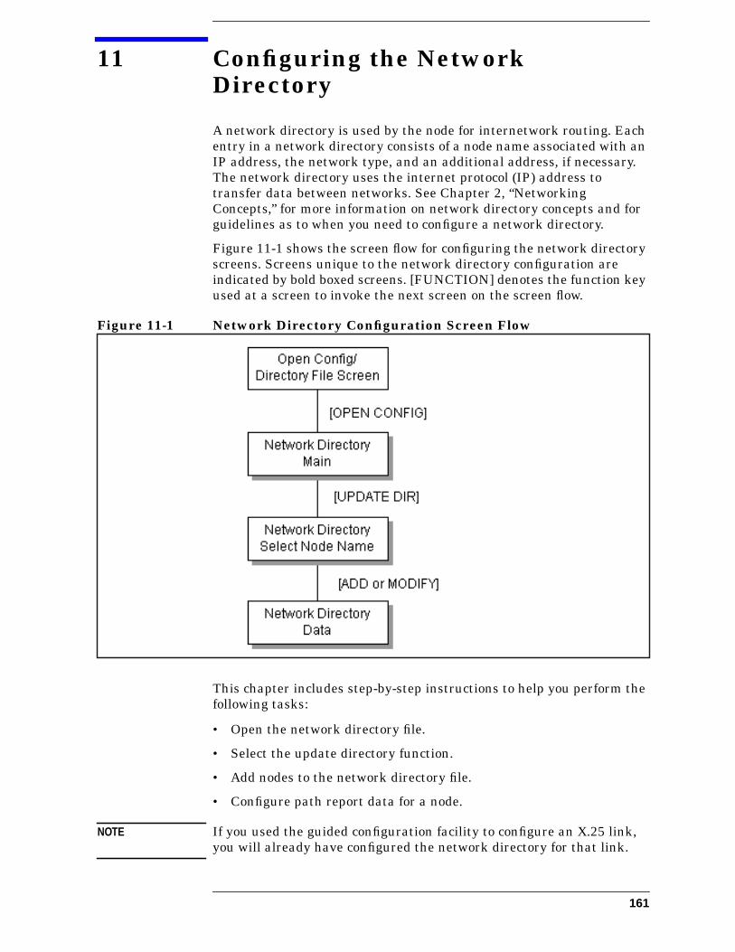
11 Configuring the NetworkDirectory
A network directory is used by the node for internetwork routing. Eachentry in a network directory consists of a node name associated with anIP address, the network type, and an additional address, if necessary.The network directory uses the internet protocol (IP) address totransfer data between networks. See Chapter 2, “NetworkingConcepts,” for more information on network directory concepts and forguidelines as to when you need to configure a network directory.
Figure 11-1 shows the screen flow for configuring the network directoryscreens. Screens unique to the network directory configuration areindicated by bold boxed screens. [FUNCTION] denotes the function keyused at a screen to invoke the next screen on the screen flow.
Figure 11-1 Network Directory Configuration Screen Flow
This chapter includes step-by-step instructions to help you perform thefollowing tasks:
• Open the network directory file.
• Select the update directory function.
• Add nodes to the network directory file.
• Configure path report data for a node.
NOTE If you used the guided configuration facility to configure an X.25 link,you will already have configured the network directory for that link.
161

Configuring the Network DirectoryTo Open the Network Directory
To Open the Network DirectoryThe Open Configuration/Directory file screen (#1) in Figure 11-2 is thefirst screen displayed when you run NMMGR.
Figure 11-2 Open Configuration/Directory File
Step 1. Verify that the correct network directory file name is in the Networkdirectory file name field.
Step 2. If you have assigned a write access password, enter it in this field. Ifyou are not using the password feature, leave this field blank.
Step 3. Press the [Open Directry] key. If you are creating the file for the firsttime, NMMGR will ask you to verify creation. Press the [Open Directry]key again to continue.
Fields Configurationfile name The only configuration file name the system recognizes
for use by the network subsystem isNMCONFIG.PUB.SYS. You can, however, create ormodify a configuration file using a different name andsave it as an offline configuration file. You can useoffline configuration files as a means of creating andstoring configurations that you want to use in thefuture or that you are preparing for use on a differentsystem. When you are ready to use an offline
162 Chapter 11
Configuring the Network DirectoryTo Open the Network Directory
configuration file, rename it as NMCONFIG.PUB.SYSand reboot the system. (Keep in mind that any file youuse as a configuration file must be successfullyvalidated before you try to use it.)
Backupconfigurationfile name A backup file name must be specified whenever a
configuration file is opened or created. The defaultbackup configuration file name isNMCBACK.group.account . The backup file will beautomatically updated with the contents of theconfiguration file each time the configuration file issuccessfully validated.
Networkdirectoryfile name The only network directory file name supported by HP
is NSDIR.NET.SYS . This file is part of a KSAM pair. Akey file is created at the same time as this data file. Thekey file will automatically be named using the first sixletters of the network directory file name, appendedwith the character K. For example, NSDIRK.NET.SYS isthe name of the key file associated with the data fileNSDIR.NET.SYS . If the name of the data file is lessthan six letters long, then the entire file name would beappended with a K.
Write accesspassword The password is an optional feature. If a password has
been assigned, you must enter it in the password fieldto update the configuration file or the directory file. It isstill possible to open an existing file without using anassigned password, but the file will be in read onlymode and no changes will be accepted.
If a password has not been assigned, you should ignorethe password field.
If you want to assign a password for the system you areconfiguring, see Using the Node Management Services(NMS) Utilities.
Chapter 11 163
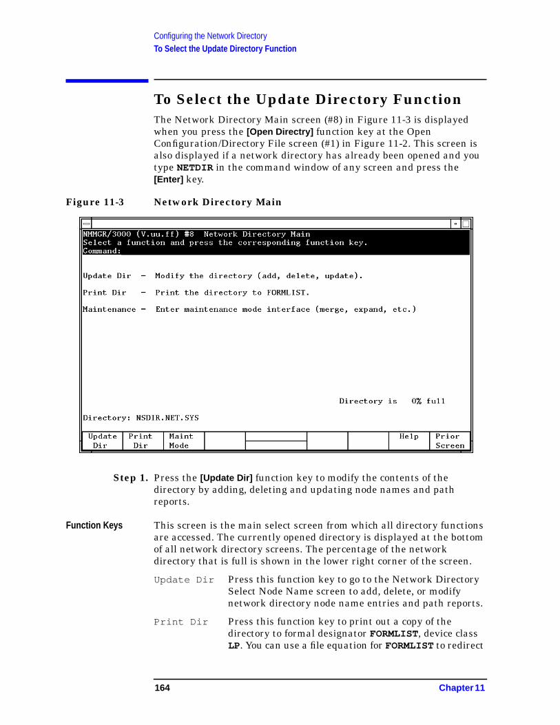
Configuring the Network DirectoryTo Select the Update Directory Function
To Select the Update Directory FunctionThe Network Directory Main screen (#8) in Figure 11-3 is displayedwhen you press the [Open Directry] function key at the OpenConfiguration/Directory File screen (#1) in Figure 11-2. This screen isalso displayed if a network directory has already been opened and youtype NETDIR in the command window of any screen and press the[Enter] key.
Figure 11-3 Network Directory Main
Step 1. Press the [Update Dir] function key to modify the contents of thedirectory by adding, deleting and updating node names and pathreports.
Function Keys This screen is the main select screen from which all directory functionsare accessed. The currently opened directory is displayed at the bottomof all network directory screens. The percentage of the networkdirectory that is full is shown in the lower right corner of the screen.
Update Dir Press this function key to go to the Network DirectorySelect Node Name screen to add, delete, or modifynetwork directory node name entries and path reports.
Print Dir Press this function key to print out a copy of thedirectory to formal designator FORMLIST, device classLP. You can use a file equation for FORMLISTto redirect
164 Chapter 11

Configuring the Network DirectoryTo Select the Update Directory Function
the output to another device class or disk file. To set afile equation without leaving NMMGR, enter theappropriate MPE command in the command windowand press the [Enter] key.
Maint Mode Press this function key to enter the command interfaceto perform directory merging or to expand the size ofyour directory. See Using the Node ManagementServices (NMS) Utilities for details on maintenancemode.
Within the maintenance mode interface, commandinput is read from the formal designator NMMGRCMD,which defaults to $STDINX. Type EXIT and press the[Enter] key to leave maintenance mode.
Chapter 11 165
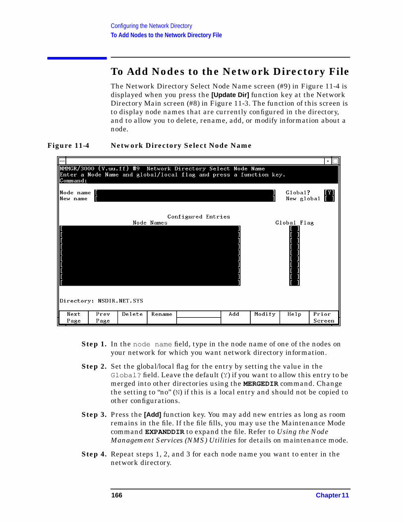
Configuring the Network DirectoryTo Add Nodes to the Network Directory File
To Add Nodes to the Network Directory FileThe Network Directory Select Node Name screen (#9) in Figure 11-4 isdisplayed when you press the [Update Dir] function key at the NetworkDirectory Main screen (#8) in Figure 11-3. The function of this screen isto display node names that are currently configured in the directory,and to allow you to delete, rename, add, or modify information about anode.
Figure 11-4 Network Directory Select Node Name
Step 1. In the node name field, type in the node name of one of the nodes onyour network for which you want network directory information.
Step 2. Set the global/local flag for the entry by setting the value in theGlobal? field. Leave the default (Y) if you want to allow this entry to bemerged into other directories using the MERGEDIR command. Changethe setting to “no” (N) if this is a local entry and should not be copied toother configurations.
Step 3. Press the [Add] function key. You may add new entries as long as roomremains in the file. If the file fills, you may use the Maintenance Modecommand EXPANDDIR to expand the file. Refer to Using the NodeManagement Services (NMS) Utilities for details on maintenance mode.
Step 4. Repeat steps 1, 2, and 3 for each node name you want to enter in thenetwork directory.
166 Chapter 11

Configuring the Network DirectoryTo Add Nodes to the Network Directory File
Fields Node name The name of the node for which you want networkdirectory information. The node name field mustcontain a fully qualified node name, in the formnodename.domain.organization , when used to add,modify, delete, or rename a node.
The node name field when used with the Prev Pageand Next Page function keys allows you to browsethrough a specified part of the network directory. Youcan enter part of a node name in this field to designatewhich node names you want displayed. For example, ifyou enter the value NIK , and press the [Next Page]function key, the list of nodes will begin with the firstmatching node name, for exampleNIKOLAI.FINANCE.IND , and continue through therest of the alphabet until all node names between theletters NIK and Z are listed.
Global? The global/local setting for node name. The acceptablevalues are Y or N. When the Prev Page and NextPage function keys are used, only node names whoseglobal/local setting matches the value in this field aredisplayed.
Entries can be configured as either global or local in thenetwork directory. Global entries (the default) can bemerged into other directories using the MERGEDIRcommand. Local entries are not merged into othernetwork directories. The local entries are used forconfiguring localized network directory entries, thusproviding a mechanism to restrict directory data frombeing propagated throughout the network.
A situation where this type of restriction could beuseful is when you want to change the configuration forusers on a single host, but not for everyone else. Youcan configure two network directory entries: one local,used by host users, and one global, used by everyoneelse when establishing connections to the host. Forexample, suppose Node A sets up a new link to Node C,but Node A does not want other nodes (alreadyconnected to A) to know about Node C until the newlink is tested. Users on Node A can configure a localentry, which contains information about the new linknot included in the global entry configured for users onother nodes.
Other uses of local entries include restricting certainnodes from communicating with the internet, or beingable to direct which way to access remote nodes
Chapter 11 167
Configuring the Network DirectoryTo Add Nodes to the Network Directory File
depending on your configuration of local entries. Whenboth local and global entries exist for the same node,the network transport uses the local entry.
Default value: Y
Range: Y or N
New name (Required only when renaming an existing node name.)New name to be assigned to the node with the Renamefunction key.
New global The global/local flag setting for the node named in thenew name field. The acceptable values are Y or N. Theonly time this field is used is when you rename a nodeor when you change the global/local setting of a node.The new name field can be left blank if you wish tochange only the global/local setting.
ConfiguredEntries (nodenames &global flag) Display-only fields that show node names and their
global/local flag settings that are already configured inthe directory.
168 Chapter 11
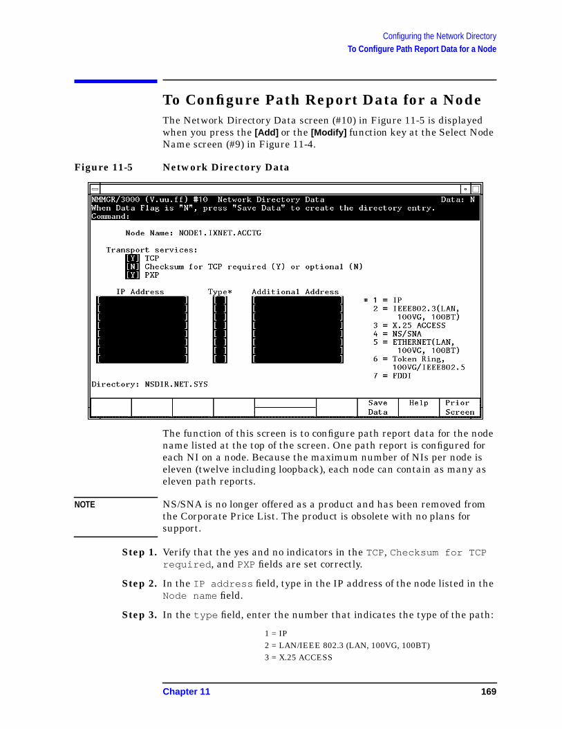
Configuring the Network DirectoryTo Configure Path Report Data for a Node
To Configure Path Report Data for a NodeThe Network Directory Data screen (#10) in Figure 11-5 is displayedwhen you press the [Add] or the [Modify] function key at the Select NodeName screen (#9) in Figure 11-4.
Figure 11-5 Network Directory Data
The function of this screen is to configure path report data for the nodename listed at the top of the screen. One path report is configured foreach NI on a node. Because the maximum number of NIs per node iseleven (twelve including loopback), each node can contain as many aseleven path reports.
NOTE NS/SNA is no longer offered as a product and has been removed fromthe Corporate Price List. The product is obsolete with no plans forsupport.
Step 1. Verify that the yes and no indicators in the TCP, Checksum for TCPrequired , and PXP fields are set correctly.
Step 2. In the IP address field, type in the IP address of the node listed in theNode name field.
Step 3. In the type field, enter the number that indicates the type of the path:
1 = IP2 = LAN/IEEE 802.3 (LAN, 100VG, 100BT)3 = X.25 ACCESS
Chapter 11 169

Configuring the Network DirectoryTo Configure Path Report Data for a Node
4 = NS/SNA5 = ETHERNET (LAN 100VG, 100BT)6 = Token Ring, 100VG/IEEE 802.57 = FDDI
Step 4. If appropriate for the type of path you are configuring, enter an addressin the Additional Address field. (Type 1 requires no additionaladdress. Types 2, 5, and 6 require a station address. Type 3 requires anX.25 address key. Type 4 requires an LU name.) See additionalexplanation under “Fields.”
Step 5. Press the [Save Data] key.
Step 6. Repeat steps 2, 3, and 4 for each path report for the specified node.
If you need to make additional entries in the network directory, pressthe [Prior Screen] key to return to the Network Directory Select NodeName screen. If you have finished making network directory entries,home the cursor and type EXIT in the command field, then press[ENTER] .
Fields Transportservices These three fields describe the transport services that
should be configured in each path.
TCP TCP must be Y (yes) for all nodes. Thedefault is Y.
Checksum forTCP The checksum setting indicates
whether checksumming is optional (N)or required (Y) for TCP. If this field isset to N, then the use of checksums isnot requested when communicatingwith this node. If this field is set to Ythen checksums are used whencommunicating with this node.Checksumming is required forcommunication to non-HP systems. Thedefault is N.
PXP PXP must be Y (yes) for all nodes. Thedefault is Y.
Note that the selection of transport services here must match thesettings in the remote node’s configuration file. If the checksum enabledfield in the path NETXPORT.GPROT.TCP of this node is set to Y, thenTCP checksum field in the network directory should also be set to Y.
170 Chapter 11

Configuring the Network DirectoryTo Configure Path Report Data for a Node
IP address One IP address should be entered for each networkinterface configured on the remote node that is directlyreachable from this node. Each address must match anIP address configured in the remote node’sconfiguration file. The path of the screen in theconfiguration file that contains IP addresses isNETXPORT.NI. NIname.PROTOCOL.IP .
Type A number indicating the type of path to configure:
1 Select this path type when the NI typeis ROUTER(Point-to-Point); or when theNI type is LANand the destination nodesupports probe or ARP; or when the NItype is TOKEN or FDDI and thedestination node supports ARP.
2 Select this path type when the NI typeis LAN, 100VG-AnyLAN or 100Base-T ,the destination node does not supportprobe, and 802.3 framing is used.
3 Select this path type when the NI typeis X25.
4 NS/SNA is no longer offered as aproduct and has been removed from theCorporate Price List.
5 Select this path type when the NI typeis LAN, 100VG-AnyLAN or 100Base-T ,the destination node does not supportARP or probe, and Ethernet framing isto be used.
6 Select this path type when the NI typeis TOKENand the destination node doesnot support ARP.
7 Select this path type when the NI typeis FDDI and the destination node doesnot support ARP.
Chapter 11 171

Configuring the Network DirectoryTo Configure Path Report Data for a Node
Table 11-1 Path Type Configuration
Additionaladdress A lower-level address, which depends on the type.
Type 1 does not contain lower-level addressinginformation. You can leave the field blank, or enter thekeyword NONE.
Types 2, 5, 6, and 7 require the destination node’sstation address, which is a string of six hexadecimalbytes, separated by dashes (XX-XX-XX-XX-XX-XX ).The station address must correspond to the addressconfigured on the remote node.
Type 3 requires an X.25 address key, which is an ASCIIstring of up to 15 characters. The X.25 address keymust correspond to an X.25 address key entered in theNETXPORT.NI. NIname.PROTOCOL.X25.SVPATHor theNETXPORT.NI. NIname.PROTOCOL.X25.PVCPATHscreen for the destination node.
Type 4 requires the destination node’s LU name. TheLU name is taken from the host generation file of theIBM computer to which this HP 3000 is connected.
N1 Type Framing Protocols Type
Point-to-Point (Router) N/A N/A 1
LAN, 100VG-AnyLAN, or100Base-T
802.3 and Ethernet Either Probe or ARP 1
802.3 and Ethernet Neither Probe nor ARP 5
802.3 only Not Probe 2
Ethernet only Not ARP 5
X.25 N/A N/A 3
NS/SNA N/A N/A 4
Token Ring N/A ARP 1
N/A Not ARP 6
FDDI N/A ARP 1
N/A Not ARP 7
172 Chapter 11

12 Configuring Domain Name Files
If you are planning to use the domain name resolver for name to IPaddress resolution, you will need to configure a set of ASCII files oneach node that contain needed information. To configure these files, youuse any standard editor to modify existing sample files according to theinstructions in this chapter. See Chapter 2, “Networking Concepts,” formore information on domain names.
This chapter details:
• How to modify the RSLVSAMP.NET.SYS file and save it asRESLVCNF.NET.SYS for use as the domain name resolver.
• How to modify the HOSTSAMP.NET.SYS file and save it asHOSTS.NET.SYS for use as the domain name host file.
• Other files you can configure to make additional informationavailable to the network.
173

Configuring Domain Name FilesTo Create or Modify the Resolver File
To Create or Modify the Resolver FileThe resolver file (RESLVCNF.NET.SYS) is an initialization file for thedomain name resolver. It contains information needed by the networkto determine how to resolve a domain name to an IP address. This file isread by the resolver routines the first time they are invoked by aprocess.
To create the resolver file, perform the following steps:
Step 1. Copy the sample file, RSLVSAMP.NET.SYS, to RESLVCNF.NET.SYS.
Step 2. Modify RESLVCNF.NET.SYS using any ASCII editor so that it containsinformation about the name servers, domain, and search order for yournetwork. The keywords included in the file are described under “Fields.”
To modify an already existing RESLVCNF.NET.SYSfile, simply use youreditor to update and save the existing file.
Fields Each entry in the resolver file consists of a keyword followed by a valueseparated by white space. The keyword and its associated value mustappear on a single line and the keyword must start the line. Figure 12-1shows an example of a resolver file. Comment lines start with a poundsign (#).
domain Enter the local domain name. Most queries for nameswithin this domain can use short names relative to thelocal domain name. If the host name does not contain adomain part, the root domain is assumed. If more thanone instance of the domain keyword is present, the lastinstance will override.
The domain name is composed of labels, with each labelseparated by a period. Each label must start with aletter or digit, and have as interior characters onlyletters, digits, hyphens (-), or underbars (_). A domainname may have any number of labels, but its totallength, including periods, is limited to 255 characters.
label[.label][...]
Domain names are not case sensitive.
search The search entry is optional and indicates the order inwhich domains should be searched for host namelookup. You should add a search entry if users on thissystem commonly try to connect to nodes in otherdomains. The search list is limited to six domains witha total of 256 characters. If more than one instance ofthe search keyword is present, the last instance willoverride.
174 Chapter 12
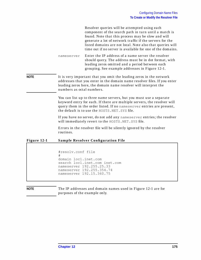
Configuring Domain Name FilesTo Create or Modify the Resolver File
Resolver queries will be attempted using eachcomponent of the search path in turn until a match isfound. Note that this process may be slow and willgenerate a lot of network traffic if the servers for thelisted domains are not local. Note also that queries willtime out if no server is available for one of the domains.
nameserver Enter the IP address of a name server the resolvershould query. The address must be in dot format, withleading zeros omitted and a period between eachgrouping. See example addresses in Figure 12-1.
NOTE It is very important that you omit the leading zeros in the networkaddresses that you enter in the domain name resolver files. If you enterleading zeros here, the domain name resolver will interpret thenumbers as octal numbers.
You can list up to three name servers, but you must use a separatekeyword entry for each. If there are multiple servers, the resolver willquery them in the order listed. If no nameserver entries are present,the default is to use the HOSTS.NET.SYS file.
If you have no server, do not add any nameserver entries; the resolverwill immediately revert to the HOSTS.NET.SYS file.
Errors in the resolver file will be silently ignored by the resolverroutines.
Figure 12-1 Sample Resolver Configuration File
NOTE The IP addresses and domain names used in Figure 12-1 are forpurposes of the example only.
#resolv.conf file#domain loc1.inet.comsearch loc1.inet.com inet.comnameserver 192.255.25.33nameserver 192.255.354.74nameserver 192.15.360.75
Chapter 12 175
Configuring Domain Name FilesTo Create or Modify the Hosts File
To Create or Modify the Hosts FileThe host name data base file, (HOSTS.NET.SYS), associates internetaddresses with official host names and aliases. This allows a user torefer to a host by a symbolic name instead of an internet address.
When you have configured the name server, this file serves only as abackup when the server is not running. In this circumstance, it is acommon practice that HOSTS.NET.SYS contains a few addresses ofmachines on the local network.
To create the hosts file, perform the following steps:
Step 1. Copy the sample file, HOSTSAMP.NET.SYS, to HOSTS.NET.SYS.
Step 2. Modify HOSTS.NET.SYS using any ASCII editor so that it containsinformation about the nodes on your network.
To modify an already existing HOSTS.NET.SYS file, simply use youreditor to update and save the existing file.
Enter a single line for each host, including the following information:
[internet address] [local host name] [aliases]
A line cannot start with a space. Items are separated by any number ofblanks and/or tab characters. A pound sign (#) indicates the beginningof a comment.
Network addresses are specified in dot format, with leading zerosomitted and a period between each grouping. (See example addresses inFigure 12-2.)
Host names can contain any printable character other than a whitespace, newline, or comment character.
NOTE It is very important that you omit the leading zeros in the networkaddresses. If you enter the leading zeros here, the domain nameresolver will interpret the numbers as octal numbers.
176 Chapter 12
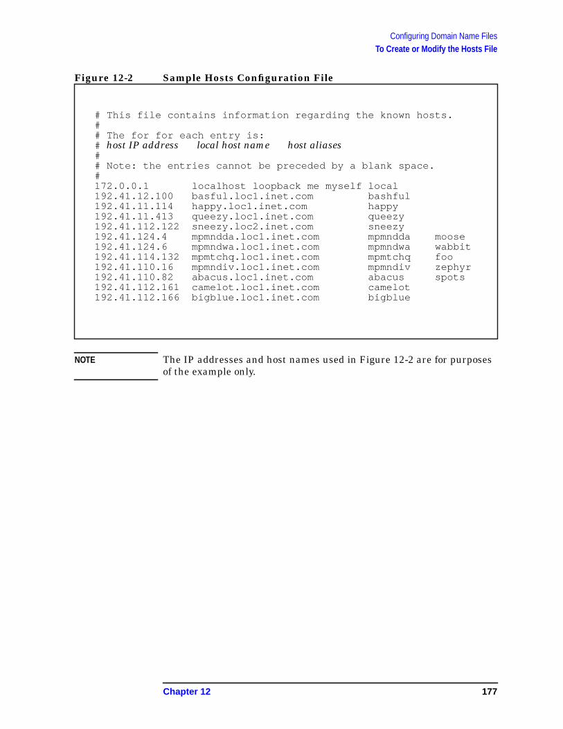
Configuring Domain Name FilesTo Create or Modify the Hosts File
Figure 12-2 Sample Hosts Configuration File
NOTE The IP addresses and host names used in Figure 12-2 are for purposesof the example only.
# This file contains information regarding the known hosts.## The for for each entry is:# host IP address local host name host aliases## Note: the entries cannot be preceded by a blank space.#172.0.0.1 localhost loopback me myself local192.41.12.100 basful.loc1.inet.com bashful192.41.11.114 happy.loc1.inet.com happy192.41.11.413 queezy.loc1.inet.com queezy192.41.112.122 sneezy.loc2.inet.com sneezy192.41.124.4 mpmndda.loc1.inet.com mpmndda moose192.41.124.6 mpmndwa.loc1.inet.com mpmndwa wabbit192.41.114.132 mpmtchq.loc1.inet.com mpmtchq foo192.41.110.16 mpmndiv.loc1.inet.com mpmndiv zephyr192.41.110.82 abacus.loc1.inet.com abacus spots192.41.112.161 camelot.loc1.inet.com camelot192.41.112.166 bigblue.loc1.inet.com bigblue
Chapter 12 177
Configuring Domain Name FilesAdditional Domain Name Configuration Files
Additional Domain Name ConfigurationFilesIn addition to the resolver file and the host name data base, three otherfiles are available to allow you to configure additional informationabout your network. Each of these files is provided in sample format inthe NET.SYS account. Each sample file contains an explanation of theformat for the data and a sample entry. The available files and theirfunctions are described as follows.
Network Name DatabaseThe network name database, NETWORKS.NET.SYS, associates IPaddresses with official network names and aliases. This allows the userto refer to a network by a symbolic name instead of an internet address.To configure the network name database, modify the sample fileNETSAMP.NET.SYS.
Protocol Name Database The protocol name database PROTOCOL.NET.SYS, associates protocolnumbers with official protocol names and aliases. This allows the userto refer to a protocol by a symbolic name instead of a number. Theprotocol number mappings are defined in RFC 1010 Assigned Numbers.To configure the protocol name database, modify the sample filePROTSAMP.NET.SYS.
Service Name DatabaseThe service name database, SERVICES.NET.SYS, associates officialservice names and aliases with the port number and protocol theservices use. Reserved port numbers 0 through 255 are assigned byRFC 1010. To configure the service name database, modify the samplefile SERVSAMP.NET.SYS.
178 Chapter 12

13 Configuring Logging
This chapter provides step-by-step instructions for configuring logging.Logging is configured for the purpose of recording events such as errorsand console commands.
Figure 13-1 shows the screen flow for configuring the logging screens.Screens unique to logging are indicated by bold boxed screens.[FUNCTION] denotes the function key used at a screen to invoke the nextscreen on the screen flow.
Figure 13-1 Logging Configuration Screen Flow
179
Configuring Logging
This chapter includes step-by-step instructions to help you perform thefollowing tasks:
• Access the logging configuration screens.
• Modify the logging configuration.
• Enable users for individual logging classes.
• Activate logging.
Logging is configured for the purpose of recording events such as errorsand console commands. You configure logging for each of thesubsystems of NS 3000/iX and for NS 3000/iX links. Each subsystemincludes different classes of events (such as internal errors). You canrecord logging to a disk file for later analysis, to the system console sothat the system operator receives the messages, or both.
You can also display logging events at individual users’ list devices.This may be valuable to allow the network manager to monitor NSconsole activity from an alternate terminal. If you configure a loggingclass so that logging is recorded to a user.account, the user will receivelogged messages any time there is an active session for thatuser.account. (Take care if you enable users for logging; doing so canplace a strain on system resources.)
The guided configuration process configures logging for you usingdefaults. You can also configure or modify the logging subsystem usingeither guided or unguided configuration.
180 Chapter 13

Configuring LoggingTo Access the Logging configuration Screens
To Access the Logging configurationScreensUse the following steps to reach the logging configuration screens:
Step 1. Run NMMGR. The Open Configuration/Directory File screen isdisplayed.
Step 2. Run NMMGR. The Open Configuration/Directory File screen isdisplayed.
Step 3. Press the [NS] function key. The NS Configuration screen is displayed.
Step 4. Press either the [Guided Config] or the [Unguided Config] function key.
Step 5. Press the [Modify Logging] function key if you are in guidedconfiguration or the [Go To Logging] function key if you are in unguidedconfiguration. The first of six logging configuration screens is displayed.
NOTE HP recommends that you use the default logging configuration valuesunless your HP representative tells you otherwise. Not using therecommended default values may result in the degradation of systemperformance.
Chapter 13 181
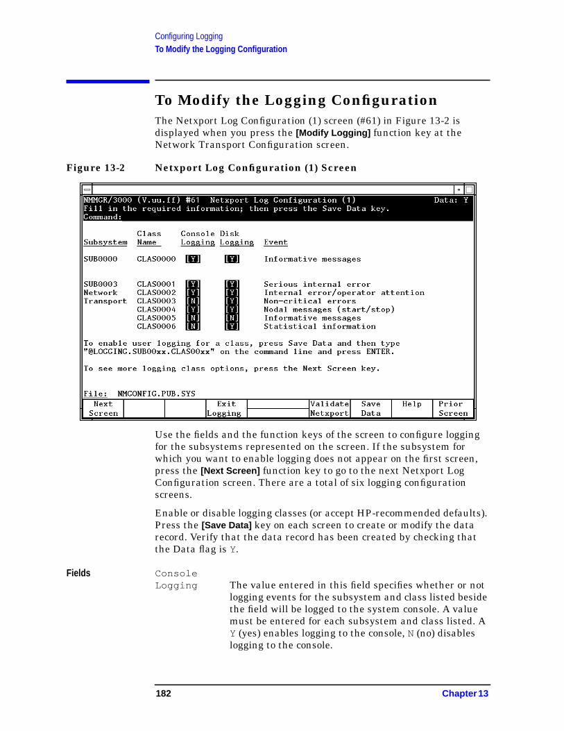
Configuring LoggingTo Modify the Logging Configuration
To Modify the Logging ConfigurationThe Netxport Log Configuration (1) screen (#61) in Figure 13-2 isdisplayed when you press the [Modify Logging] function key at theNetwork Transport Configuration screen.
Figure 13-2 Netxport Log Configuration (1) Screen
Use the fields and the function keys of the screen to configure loggingfor the subsystems represented on the screen. If the subsystem forwhich you want to enable logging does not appear on the first screen,press the [Next Screen] function key to go to the next Netxport LogConfiguration screen. There are a total of six logging configurationscreens.
Enable or disable logging classes (or accept HP-recommended defaults).Press the [Save Data] key on each screen to create or modify the datarecord. Verify that the data record has been created by checking thatthe Data flag is Y.
Fields ConsoleLogging The value entered in this field specifies whether or not
logging events for the subsystem and class listed besidethe field will be logged to the system console. A valuemust be entered for each subsystem and class listed. AY (yes) enables logging to the console, N (no) disableslogging to the console.
182 Chapter 13

Configuring LoggingTo Modify the Logging Configuration
Disk Logging The value entered in this field specifies whether or notlogging events for the subsystem and class listed besidethe field will be logged to a disk file. A value must beentered for each subsystem and class listed. A Y (yes)enables logging to a file, N (no) disables logging to a file.The file name for the log file is NMLGnnnn.PUB.SYS ,where nnnn is a number from 0000to 9999. All loggingclasses in all subsystems are logged to this file. At eachsystem startup, or when a file is full, the nodemanagement services subsystem (NMS) creates a newNMLGnnnn.PUB.SYS file, naming each successivelogging file by incrementing nnnn. WhenNMLG9999.PUB.SYS is full, NMS names the nextlogging file NMLG0000.PUB.SYS .
The Netxport Log Configuration (2) screen (#60) in Figure 13-3 isdisplayed when you press the [Next Screen] function key from theNetxport Log Configuration (1) screen (#61) in Figure 13-2.
Figure 13-3 Netxport Log Configuration (2) Screen
Use the fields and the function keys of the screen to configure loggingfor the subsystems represented on the screen. If the subsystem forwhich you want to enable logging does not appear on this screen, pressthe [Next Screen] function key to go to the next Netxport LogConfiguration screen. There are a total of six logging configurationscreens.
Chapter 13 183

Configuring LoggingTo Modify the Logging Configuration
Enable or disable logging classes (or accept HP-recommended defaults).Press the [Save Data] key on each screen to create or modify the datarecord. Verify that the data record has been created by checking thatthe Data flag is Y.
Fields ConsoleLogging The value entered in this field specifies whether or not
logging events for the subsystem and class listed besidethe field will be logged to the system console. A valuemust be entered for each subsystem and class listed. AY (yes) enables logging to the console, N (no) disableslogging to the console.
Disk Logging The value entered in this field specifies whether or notlogging events for the subsystem and class listed besidethe field will be logged to a disk file. A value must beentered for each subsystem and class listed. A Y (yes)enables logging to a file, N (no) disables logging to a file.The file name that NMS uses is NMLGnnnn.PUB.SYS ,where nnnn is a number from 0000 to 9999. All loggingclasses in all subsystems are logged to this file. At eachsystem startup, or when a file is full, NMS creates anew NMLGnnnn.PUB.SYS file, naming each successivelogging file by incrementing nnnn. WhenNMLG9999.PUB.SYS is full, NMS names the nextlogging file NMLG0000.PUB.SYS .
The Netxport Log Configuration (3) screen (#70) in Figure 13-4 isdisplayed when you press the [Next Screen] function key from theNetxport Log Configuration (2) screen (#60) in Figure 13-3.
184 Chapter 13
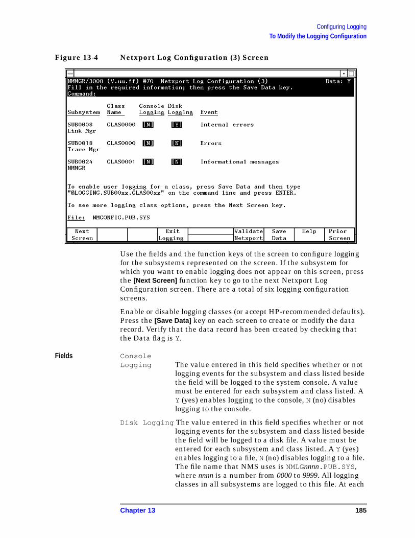
Configuring LoggingTo Modify the Logging Configuration
Figure 13-4 Netxport Log Configuration (3) Screen
Use the fields and the function keys of the screen to configure loggingfor the subsystems represented on the screen. If the subsystem forwhich you want to enable logging does not appear on this screen, pressthe [Next Screen] function key to go to the next Netxport LogConfiguration screen. There are a total of six logging configurationscreens.
Enable or disable logging classes (or accept HP-recommended defaults).Press the [Save Data] key on each screen to create or modify the datarecord. Verify that the data record has been created by checking thatthe Data flag is Y.
Fields ConsoleLogging The value entered in this field specifies whether or not
logging events for the subsystem and class listed besidethe field will be logged to the system console. A valuemust be entered for each subsystem and class listed. AY (yes) enables logging to the console, N (no) disableslogging to the console.
Disk Logging The value entered in this field specifies whether or notlogging events for the subsystem and class listed besidethe field will be logged to a disk file. A value must beentered for each subsystem and class listed. A Y (yes)enables logging to a file, N (no) disables logging to a file.The file name that NMS uses is NMLGnnnn.PUB.SYS ,where nnnn is a number from 0000 to 9999. All loggingclasses in all subsystems are logged to this file. At each
Chapter 13 185
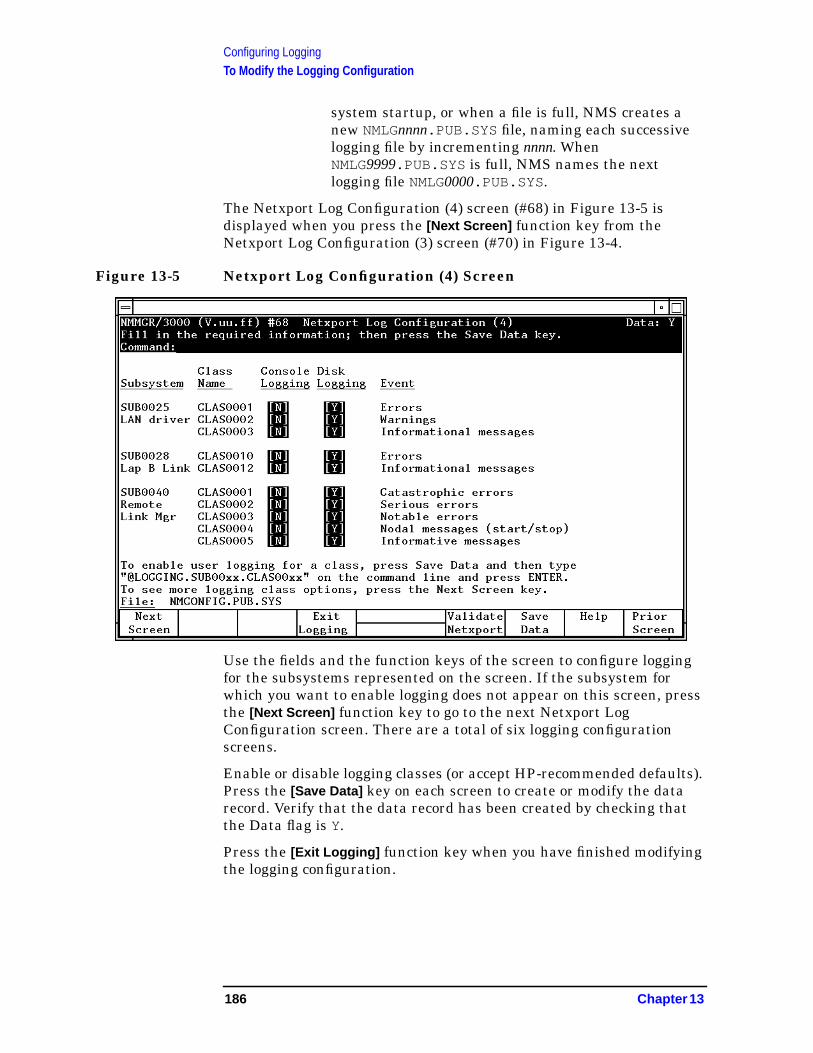
Configuring LoggingTo Modify the Logging Configuration
system startup, or when a file is full, NMS creates anew NMLGnnnn.PUB.SYS file, naming each successivelogging file by incrementing nnnn. WhenNMLG9999.PUB.SYS is full, NMS names the nextlogging file NMLG0000.PUB.SYS .
The Netxport Log Configuration (4) screen (#68) in Figure 13-5 isdisplayed when you press the [Next Screen] function key from theNetxport Log Configuration (3) screen (#70) in Figure 13-4.
Figure 13-5 Netxport Log Configuration (4) Screen
Use the fields and the function keys of the screen to configure loggingfor the subsystems represented on the screen. If the subsystem forwhich you want to enable logging does not appear on this screen, pressthe [Next Screen] function key to go to the next Netxport LogConfiguration screen. There are a total of six logging configurationscreens.
Enable or disable logging classes (or accept HP-recommended defaults).Press the [Save Data] key on each screen to create or modify the datarecord. Verify that the data record has been created by checking thatthe Data flag is Y.
Press the [Exit Logging] function key when you have finished modifyingthe logging configuration.
186 Chapter 13
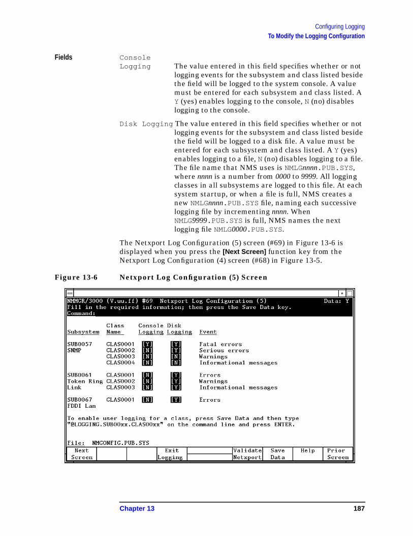
Configuring LoggingTo Modify the Logging Configuration
Fields ConsoleLogging The value entered in this field specifies whether or not
logging events for the subsystem and class listed besidethe field will be logged to the system console. A valuemust be entered for each subsystem and class listed. AY (yes) enables logging to the console, N (no) disableslogging to the console.
Disk Logging The value entered in this field specifies whether or notlogging events for the subsystem and class listed besidethe field will be logged to a disk file. A value must beentered for each subsystem and class listed. A Y (yes)enables logging to a file, N (no) disables logging to a file.The file name that NMS uses is NMLGnnnn.PUB.SYS ,where nnnn is a number from 0000 to 9999. All loggingclasses in all subsystems are logged to this file. At eachsystem startup, or when a file is full, NMS creates anew NMLGnnnn.PUB.SYS file, naming each successivelogging file by incrementing nnnn. WhenNMLG9999.PUB.SYS is full, NMS names the nextlogging file NMLG0000.PUB.SYS .
The Netxport Log Configuration (5) screen (#69) in Figure 13-6 isdisplayed when you press the [Next Screen] function key from theNetxport Log Configuration (4) screen (#68) in Figure 13-5.
Figure 13-6 Netxport Log Configuration (5) Screen
Chapter 13 187
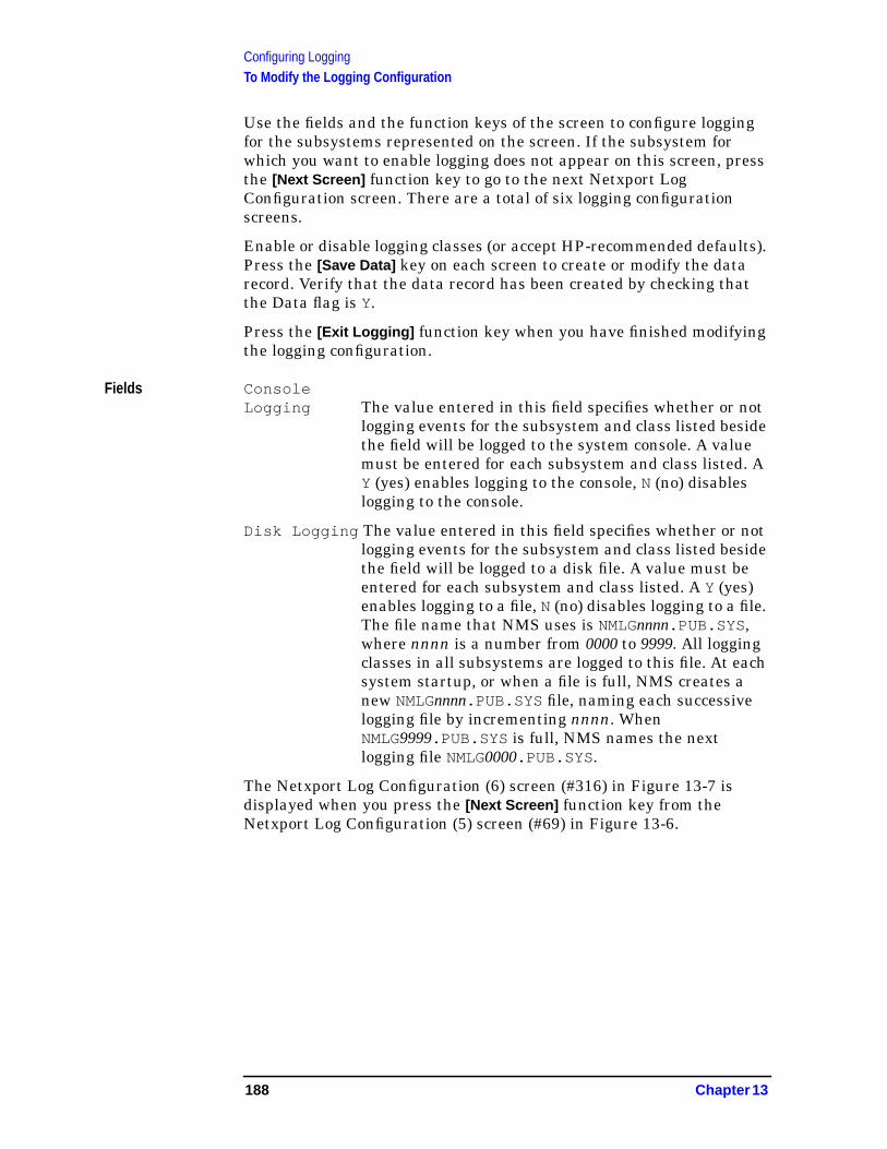
Configuring LoggingTo Modify the Logging Configuration
Use the fields and the function keys of the screen to configure loggingfor the subsystems represented on the screen. If the subsystem forwhich you want to enable logging does not appear on this screen, pressthe [Next Screen] function key to go to the next Netxport LogConfiguration screen. There are a total of six logging configurationscreens.
Enable or disable logging classes (or accept HP-recommended defaults).Press the [Save Data] key on each screen to create or modify the datarecord. Verify that the data record has been created by checking thatthe Data flag is Y.
Press the [Exit Logging] function key when you have finished modifyingthe logging configuration.
Fields ConsoleLogging The value entered in this field specifies whether or not
logging events for the subsystem and class listed besidethe field will be logged to the system console. A valuemust be entered for each subsystem and class listed. AY (yes) enables logging to the console, N (no) disableslogging to the console.
Disk Logging The value entered in this field specifies whether or notlogging events for the subsystem and class listed besidethe field will be logged to a disk file. A value must beentered for each subsystem and class listed. A Y (yes)enables logging to a file, N (no) disables logging to a file.The file name that NMS uses is NMLGnnnn.PUB.SYS ,where nnnn is a number from 0000 to 9999. All loggingclasses in all subsystems are logged to this file. At eachsystem startup, or when a file is full, NMS creates anew NMLGnnnn.PUB.SYS file, naming each successivelogging file by incrementing nnnn. WhenNMLG9999.PUB.SYS is full, NMS names the nextlogging file NMLG0000.PUB.SYS .
The Netxport Log Configuration (6) screen (#316) in Figure 13-7 isdisplayed when you press the [Next Screen] function key from theNetxport Log Configuration (5) screen (#69) in Figure 13-6.
188 Chapter 13
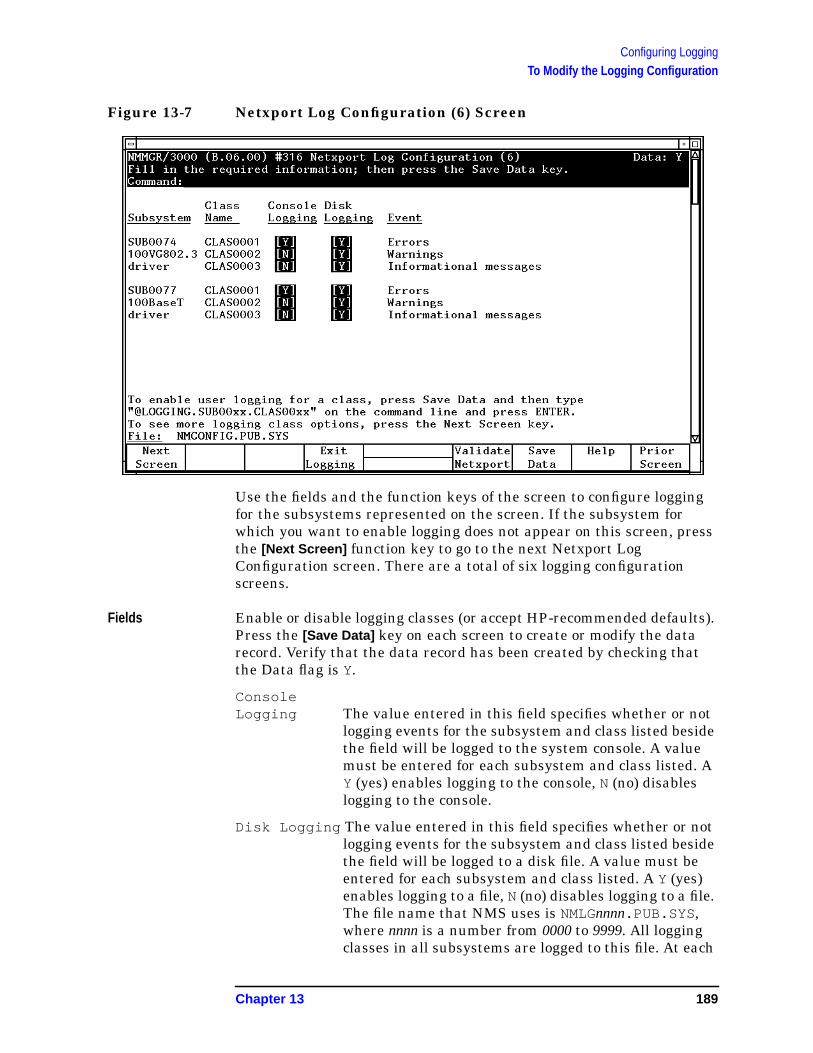
Configuring LoggingTo Modify the Logging Configuration
Figure 13-7 Netxport Log Configuration (6) Screen
Use the fields and the function keys of the screen to configure loggingfor the subsystems represented on the screen. If the subsystem forwhich you want to enable logging does not appear on this screen, pressthe [Next Screen] function key to go to the next Netxport LogConfiguration screen. There are a total of six logging configurationscreens.
Fields Enable or disable logging classes (or accept HP-recommended defaults).Press the [Save Data] key on each screen to create or modify the datarecord. Verify that the data record has been created by checking thatthe Data flag is Y.
ConsoleLogging The value entered in this field specifies whether or not
logging events for the subsystem and class listed besidethe field will be logged to the system console. A valuemust be entered for each subsystem and class listed. AY (yes) enables logging to the console, N (no) disableslogging to the console.
Disk Logging The value entered in this field specifies whether or notlogging events for the subsystem and class listed besidethe field will be logged to a disk file. A value must beentered for each subsystem and class listed. A Y (yes)enables logging to a file, N (no) disables logging to a file.The file name that NMS uses is NMLGnnnn.PUB.SYS ,where nnnn is a number from 0000 to 9999. All loggingclasses in all subsystems are logged to this file. At each
Chapter 13 189
Configuring LoggingTo Modify the Logging Configuration
system startup, or when a file is full, NMS creates anew NMLGnnnn.PUB.SYS file, naming each successivelogging file by incrementing nnnn. WhenNMLG9999.PUB.SYS is full, NMS names the nextlogging file NMLG0000.PUB.SYS .
190 Chapter 13

Configuring LoggingTo Enable Users for Individual Logging Classes
To Enable Users for Individual LoggingClasses
The logging screens described previously in this chapter make itpossible to completely configure logging for all subsystems bytraversing only six screens. However, using these screens, it is notpossible to configure logging so that messages generated by specificlogging classes are sent to an individual user’s list device.
The following steps describe the method used to configure users toreceive logging messages. Using this method, you can create aconfiguration that allows messages from a single logging class, or a setof classes, to be sent to a user’s list device.
To do so, you access and update the Logging Configuration Class Datascreen (#67) in Figure 13-7, according to the steps that follow.
Figure 13-8 Logging Configuration: Class Data Screen
Step 1. Type the path name:
LOGGING.SUBnnnn.CLASnnnn
in the command window of any screen and press the [ENTER] key, whereSUBnnnn is the subsystem ID and CLASnnnn is the class name of thelogging class you want directed to the user’s list device.
Chapter 13 191

Configuring LoggingTo Enable Users for Individual Logging Classes
Step 2. To enable console logging for this subsystem logging class, enter a Y inthe Enable console logging? field. To disable console logging, enteran N. Be aware that changing the value in this field will overridethe previous setting for the logging class you are configuring.
Step 3. To enable disk logging for this subsystem logging class, enter a Y in theEnable disk logging? field. To disable console logging, enter an N.Be aware that changing the value in this field will override theprevious setting for the logging class you are configuring.
Step 4. Enter up to three names, in the form user.account , in the Usersenabled for logging fields. If these fields already contain names itis because user names were previously configured using this screen. Ifless than three user names are configured, type the new user name inan empty field. If all fields are used, type over one of the old user namesto replace it with the new user name. (Note that the user name you typeover will no longer be enabled to receive these logging messages.)
Step 5. Press the [Save Data] function key to modify the data record.
Step 6. Press the [Prior Screen] key to return to the screen from which youaccessed the Logging Configuration: Class Data screen.
Repeat the above procedure for each subsystem logging class for whichyou want to enable users.
CAUTION Enabling users to receive logging messages can strain systemresources. Hewlett-Packard recommends that you use this capabilitysparingly and only for short periods of time.
192 Chapter 13
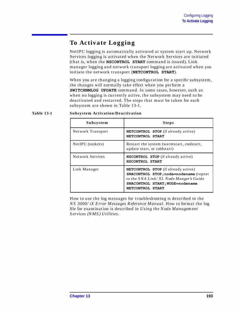
Configuring LoggingTo Activate Logging
To Activate LoggingNetIPC logging is automatically activated at system start up. NetworkServices logging is activated when the Network Services are initiated(that is, when the NSCONTROL START command is issued). Linkmanager logging and network transport logging are activated when youinitiate the network transport (NETCONTROL START).
When you are changing a logging configuration for a specific subsystem,the changes will normally take effect when you perform aSWITCHNMLOG UPDATE command. In some cases, however, such aswhen no logging is currently active, the subsystem may need to bedeactivated and restarted. The steps that must be taken for eachsubsystem are shown in Table 13-1.
Table 13-1 Subsystem Activation/Deactivation
How to use the log messages for troubleshooting is described in theNS 3000/iX Error Messages Reference Manual. How to format the logfile for examination is described in Using the Node ManagementServices (NMS) Utilities.
Subsystem Steps
Network Transport NETCONTROL STOP (if already active)NETCONTROL START
NetIPC (sockets) Restart the system (warmstart, coolstart,update start, or coldstart)
Network Services NSCONTROL STOP (if already active)NSCONTROL START
Link Manager NETCONTROL STOP (if already active)SNACONTROL STOP;node=nodename (repeatto the SNA Link/XL Node Manger’s GuideSNACONTROL START;NODE=nodenameNETCONTROL START
Chapter 13 193

Configuring LoggingTo Activate Logging
194 Chapter 13

14 Operating the Network
After you have completed the configuration process, you are ready toactivate NS. This chapter shows you how to bring up an NS 3000/iXnode and how to shut it down. It assumes you have successfullycompleted the configuration steps described previously.
For more detailed information on starting, stopping, and operating anNS network, see the NS 3000/iX Operations and MaintenanceReference Manual.
This chapter includes step-by-step instructions to help you perform thefollowing tasks:
• Start links and services.
• Start software loopback (optional).
• Start the links.
• Start Network Services.
• Test Network Services.
• Shut down links and services.
195
Operating the NetworkTo Start Links and Services
To Start Links and Services
To Start Software LoopbackIssue the following command (NM capability required) to start softwareloopback:
NETCONTROL START;NET=loopbackNIname
This starts up the control process, the transport, and software loopback.Note: when you use guided NMMGR to create any NI, a loopbacknetwork interface (whose loopbackNIname is LOOP) is automaticallygenerated. The loopback NI must be started if you wish to perform localloopbacks or to DSLINE to the local node.
To Start a LinkIssue the following command (NM capability required) to start a link:
NETCONTROL START;NET=NIname
This starts the link identified by the NI name. (If no previousNETCONTROL STARTcommand was issued, then the control process andtransport are also started.) The NIname is the network interface (NI)name that you supplied during NS configuration. You can start the linkbefore loopback if you want. Start other links as needed.
To Start a Host-Based X.25 LinkIf your network includes X.25 links and you are using host-basednetwork management, you will need to use the DTCCNTRL commandbefore you issue the NETCONTROL START command. DTCCNTRL startsX.25 and PAD support for the DTC/X.25 Network Access card. Issue thefollowing command (System Operator capability required):
DTCCNTRL DTC=dtcname ;CARD=cardnumber ;FUNC=function
where function is one of the following:
STARTX25 to start X.25 services;
STARTPADSUPto start PAD support services;
STARTBOTH to start both X.25 and PAD support services.
For more information on starting host-based X.25 links as well as otheruses of the DTCCNTRL command, see Configuring and ManagingHost-Based X.25 Links.
NOTE If you are starting an X.25 link for a system using PC-based networkmanagement or if you are not starting an X.25 link, you do not need touse the DTCCNTRL command.
196 Chapter 14

Operating the NetworkTo Start Links and Services
To Start the Network ServicesIssue the following command (NM capability required) to start thenetwork services:
NSCONTROL START
This starts the NS 3000/iX Network Services, such as Virtual Terminal,Network File Transfer, Remote File Access, and Remote Data BaseAccess.
You may want to create a startup UDC or command file to activatesoftware loopback, the link(s), and the network services.
Chapter 14 197
Operating the NetworkTo Test the Network Services
To Test the Network ServicesIn order to test that you have successfully configured and brought upyour NS node, HP provides an NS validation test calledQVALNS.NET.SYS. QVALNS is a program which modifies a file calledTQVALNS and streams it as a temporary job (JQVALNS). The job purgesand creates various files, and then runs a program called NSTEST.NSTEST tests the network services (VT, RFA, RDBA, and NFT).
To run the NS validation test, follow the step below:
Step 1. Run the NS validation test on your own node. This tests the softwareloopback capability. Issue the following command, where node is thenode portion of your own node name:
RUN QVALNS.NET.SYS;INFO=node
Step 2. Run the NS validation test on another system on the same network.Select a remote node on the network and make sure that the link andthe network services are up on the remote system by issuing thefollowing commands on that node (NM capability required):
NETCONTROL STATUS
NSCONTROL STATUS
If the link or network services have not been started, either pickanother node or start them.
Note the node name of the remote node (given in the last line of outputfrom the NETCONTROL STATUS command). If you followed theconfiguration steps in this manual, the second and third portions of thenode name (the domain and organization) should be the same as thesecond and third portions of the local node.
Step 3. Run the NS validation test across the link by issuing the followingcommand at the local node, where node is the node portion of theremote node name:
RUN QVALNS.NET.SYS;INFO=node
If you encounter problems, see the NS 3000/iX Operations andMaintenance Reference Manual and to the NS 3000/iX Error MessagesReference Manual for information on diagnostics and troubleshooting.
198 Chapter 14
Operating the NetworkTo Shut Down the Network Services
To Shut Down the Network ServicesTo shut down NS, issue the following commands (NM capabilityrequired):
DSLINE @;CLOSE
NSCONTROL STOP
NETCONTROL STOP
The DSLINE command shown above closes connections for your sessiononly.
NSCONTROL STOP allows existing users to continue using the servicesuntil they finish their current task but prevents new uses of theservices by these users or by new users. Therefore, the services are notactually stopped until all existing users finish using them. You can useNSCONTROL ABORT instead if you wish to immediately terminate alluse of the services.
NETCONTROL STOP closes all open connections. To determine if thereare any sessions still active, enter: NSCONTROL STATUS. If you do notwant to wait until existing users are finished with their current tasksbefore you bring down the system, issue NSCONTROL ABORT and thenNETCONTROL STOP.
If a host-based X.25 link is started, you will also need to issue aDTCCNTRL command to stop X.25 and PAD support for the DTC/X.25Network Access card. Enter the DTCCNTRL command after theNSCONTROL STOP and NETCONTROL STOP commands. Enter thecommand as:
DTCCNTRL DTC=dtcname;CARD=cardnumber;FUNC=function
where function is one of the following:
STARTX25 to start X.25 services;
STARTPADSUPto start PAD support services;
STARTBOTH to start both X.25 and PAD support services.
Chapter 14 199

Operating the NetworkTo Shut Down the Network Services
200 Chapter 14
A MPE/V to MPE/iX Migration
This appendix provides a quick overview of the planning and tasks youwill need to do to migrate an NS 3000 network from an MPE/V systemto an MPE/iX system. This appendix assumes that you are migratingyour network as a whole; that is, replacing all MPE V systems withMPE/iX systems and maintaining the same basic network function.
The following topics are covered by this appendix:
• Differences between NS 3000/V and NS 3000/iX networks.
• An overview of migration tasks.
• Guidelines for converting files.
• Guidelines for reconfiguring a network.
NOTE For information on migrating X.25 links, refer to the remainingappendixes of this manual.
201
MPE/V to MPE/iX MigrationDifferences Between NS 3000/V and NS 3000/iX
Differences Between NS 3000/V andNS 3000/iXThere are a number of differences between the way NS is implementedon MPE V systems and the way it is implemented on MPE/iX systems.These differences affect the network itself, some of the applications thatusers may run over the network, and the command used to obtainstatus information about the network. Since it is helpful to understandthese differences as you prepare to move an existing MPE V network toMPE/iX, they are summarized below.
Differences in the NetworkA number of the methods available for making connections to anMPE V network are not available with NS 3000/iX. If your MPE Vnetwork includes one of these you will need to modify your networkconfiguration before attempting to use the network on MPE/iX systems.More information on the specific steps required to modify or removeunsupported links or connections can be found later in this appendix.
The connection methods that are not supported on NS 3000/iX are:
• Manual dial modems.
• Asynchronous Network Link.
• Bisynchronous link-level protocol.
In addition, while it is possible to access a DS/3000 node directly froman NS 3000/V node, this capability is not supported on NS 3000/iX. Auser of an NS 3000/iX network who wants to access a DS/3000 nodemust first access an MPE V NS node. This is because the DS/3000 codethat was included as a subset of the NS 3000/V code is not providedwith NS 3000/iX.
Differences in Configuration FilesNS 3000/V network configuration files are separated into two files, theNMCONFIG file, which contains link information, and the NSCONF file,which contains the transport configuration and other subsystems youhave purchased such as SNA.
NS 3000/iX systems have a single NMCONFIG.PUB.SYS file thatcontains information for the network transport, for NetIPC andlink-level logging, and also for the Datacommunications and TerminalSubsystem (DTS). NMCONFIG.PUB.SYS also contains information forany other subsystems you have purchased such as SNA.
202 Appendix A

MPE/V to MPE/iX MigrationDifferences Between NS 3000/V and NS 3000/iX
Differences in Applications SupportThere are also differences in the implementations of NS 3000/V andNS 3000/iX that will affect certain applications that users maycurrently be running on your MPE V network. These differences are asfollows:
• NS 3000/iX supports PTOP for HPDESK only.
On NS 3000/iX PTOP is not supported for applications other thanHPDESK. Network users who are running PTOP programs willneed to convert them to NetIPC/RPM programs before running themon an NS 3000/iX network. Refer to the NetIPC 3000/XLProgrammer’s Reference Manual and the Using NS 3000/iXNetwork Services for more information.
• Nowait I/O RFA is not available with NS 3000/iX.
Privileged mode programs that use nowait I/O Remote File Accessover an MPE V network will need to be modified before they can berun on an NS 3000/iX network. Refer to the Using NS 3000/iXNetwork Services for more information.
Difference in How to Obtain Status InformationOn MPE V systems the SHOWCOM command returns status informationabout a communication device, and is used to determine line activityand quality. This information is still available on NS 3000/iX, but isaccessed through a different command. Use the LINKCONTROL STATUScommand to access status information on NS 3000/iX.
Appendix A 203
MPE/V to MPE/iX MigrationMigration Overview
Migration OverviewThere are a number of steps that you must take to successfully convertan MPE V network for use as an MPE/iX network. These tasks aresummarized below, and described in more detail in the remainder ofthis appendix. Keep in mind that, depending on the needs of yourinstallation, you may need to perform additional tasks to complete yourmigration. For example, if you are adding communication links that didnot exist on your MPE V network you will also need to configure thosenew links.
Before You StartThis guide provides an extensive overview of NS architecture andnetworking concepts. It also furnishes configuration design checks,planning worksheets and examples to aid you in organizing newnetwork configurations. You should be thoroughly familiar with thismaterial before you begin your migration.
File Migration TasksThere are two primary tasks you will need to perform to migrate yournetwork configuration files. These are:
1. Run the NMMGRVER utility on the old configuration files to convertthem to the current software version. (You will first need to install acopy of all configuration files used for your NS 3000/V network to theMPE/iX network). Refer to “File Conversion Guidelines” later in thisAppendix.
2. Run the NMMGR utility on the new configuration file(s) to make anychanges required due to the differences between NS 3000/V andNS 3000/iX. Refer to “Reconfiguration Guidelines” later in thisAppendix.
Additional Migration ConsiderationsThis appendix does not discuss hardware migration considerations;however, you will find a description of hardware components in thismanual. Additionally, details of hardware installation andconfiguration can be found in the following manuals:
• LANIC Installation and Service Manual.
• LAN Cable and Accessories Installation Manual.
• Central Bus Programmable Serial Interface Installation andReference Manual.
204 Appendix A
MPE/V to MPE/iX MigrationFile Conversion Guidelines
File Conversion GuidelinesA file conversion utility called NMMGRVER.PUB.SYS allows you toconvert earlier versions of subsystems for use with the current versionof Node Management Services (NMS) by converting the files to anacceptable format.
When you Need to Convert FilesIf you have not successfully converted your files you will be notified thatconversion is necessary when you try either to run NMMGR or toperform a NETCONTROL command. If you attempt to run NMMGRagainst an unconverted configuration file you will receive the message:
Version mismatch found on specified subsystem. Pleaserun NMMGRVER. (NMGRERR 53)
If you attempt to perform NETCONTROL while using unconverted filesyou will receive the following message at the console:
Bad CONFIG File Version
In either case you should stop your current activity and run theNMMGRVER.PUB.SYS file conversion utility on your configuration files.
WARNING The conversion procedure that follows will not preserve anypreviously configured Distributed Terminal Subsystem (DTS)configuration values. If you are updating from an earlierversion of MPE/iX at the same time you are migrating fromNS 3000/V to NS 3000/iX, you should see the information under“To Update From a Previous MPE/iX Version” later in thisAppendix before converting your configuration files.
To Convert FilesYou should follow these steps to convert your configuration files usingNMMGRVER:
Step 1. Make a backup copy of the existing configuration files.
Step 2. Install a copy of the MPE/V NMCONFIG file to NMCONFIG.PUB.SYS onthe MPE/iX system, and then install copies of any NSCONF files.
Step 3. Execute NMMGRVER.PUB.SYS by entering:
RUN NMMGRVER.PUB.SYS
The system responds with the following banner:
NMS Configuration File Conversion Utility 32099-11018 V.uu.ff (C)Hewlett-Packard Co. 1985
Appendix A 205
MPE/V to MPE/iX MigrationFile Conversion Guidelines
Step 4. The system will then prompt for the name of the configuration file to beconverted by displaying the message:
Fileset to be scanned?
You can then choose to end the conversion program by pressing the[RETURN] key, or you can enter one of the following filesets:
filename [.groupname [.acctname]]
@ [.groupname [.acctname]]
@.@ [.acctname]
@.@.@
NMMGRVER searches for files of type nconf in the specified fileset.For each file found, it asks:
OK to convert filename.groupname.acctname?
where filename.groupname.acctname is the name of aconfiguration file. Enter Y for yes, or enter either N or [RETURN] for no.
Step 5. NMMGRVER checks the configuration file to determine whether it isan MPE/V or an MPE/iX configuration file. If it is an MPE/iX file theconversion proceeds without further user input. If the file is an MPE/Vfile, however, NMMGRVER prompts you for the type of MPE/V file youare converting, as follows:
What is the type of this file?
1) MPE V NSCONF
2) MPE V NMCONFIG
3) skip this file
Enter a value between 1 and 3.
Enter the appropriate value.
Step 6. After each file is converted NMMGRVER will display the followingmessage:
FILE CONVERTED
Continue to enter either Y, N, or [RETURN] until you have converted allfiles.
In the conversion process, NMMGRVER will merge the informationfrom each NSCONF file accepted for conversion withNMCONFIG.PUB.SYS, and create new (converted) NSCONF files. If youhave converted more than one NSCONF file, you will need to choose thefile that corresponds to the network configuration you want, and
206 Appendix A

MPE/V to MPE/iX MigrationFile Conversion Guidelines
rename it as the new NMCONFIG.PUB.SYS. Choose the NSCONFfile thatcorresponds to the network configuration you want to use as yourNS 3000/iX configuration.
This new NMCONFIG.PUB.SYS file contains your NS configuration in aformat acceptable to MPE/iX. You can now run NMMGR to configurethe DTS subsystem, and to perform any needed modifications to the NSconfiguration. See “Reconfiguration Guidelines” later in this appendix.
To Update From a Previous MPE/iX VersionIf you are updating from an earlier version of MPE/iX at the same timeyou are migrating from NS 3000/V to NS 3000/iX, you will need tomake a choice between reconfiguring your Distributed TerminalSubsystem (DTS) and reconfiguring your NS network. The choice isnecessary because MPE/V versions of NMCONFIG.PUB.SYS files do notinclude DTS configuration values.
You should let the circumstances of your installation determine whichconfiguration values you preserve. If your NS network is complex, youmay decide to convert the existing MPE/V configuration files, andreconfigure DTS. In this case you should follow the steps under “FileConversion Guidelines” earlier in this appendix.
If, on the other hand, your DTS configuration is extensive, you maydecide to migrate your existing MPE/iX configuration files to the newversion of MPE/iX. You will then need to redo your NS networkconfiguration so that both the NS and DTS configurations are containedin a single, valid, MPE/iX NMCONFIG.PUB.SYS file. In any case, youwill need to reconfigure either NS or DTS if you are both updatingMPE/iX and converting from an NS 3000/V network to an NS 3000/iXnetwork.
Appendix A 207
MPE/V to MPE/iX MigrationReconfiguration Guidelines
Reconfiguration GuidelinesOnce your MPE/V NS configuration files have been converted for usewith the MPE/iX version of NS you will need to reconfigure yournetwork to account for the implementation differences betweenNS 3000/V and NS 3000/iX. Run the NMMGR utility against theconfiguration file generated by the file conversion process and performthe following reconfiguration tasks:
• Configure the physical path of all links for your network. Thisconfiguration consists of a channel number (ccc ) and subchannelnumber (sss ) in the form ccc.sss . There is no channel orsubchannel associated with NS on MPE V.
• Since the LAP-B protocol is the only point-to-point link-level protocolsupported on the MPE/iX computer, you must reconfigure links thatwere configured as bisynchronous links on NS 3000/V as LAP-Blinks, or remove them from the network configuration.
• Configure the Distributed Terminal Subsystem (DTS) according tothe needs of your installation. Refer to Configuring Systems forTerminals, Printers, and Other Serial Devices for instructions on howto configure the DTS.
The above configuration tasks are a general summary of what you willneed to do to reconfigure your network to run on MPE/iX. You should beaware that there are many changes to individual screens and screenfields. Refer to this guide for information on individual screens andscreen fields.
208 Appendix A
B NS X.25 Migration: NS 3000/XLReleases 1.0, 1.1, or 1.2 to
NS 3000/iX Release 2.0 or Later
This Appendix tells how to use the NMMGRVER utility to migrate(update) a node’s configuration file from NS 3000/XL releases 1.0, 1.1,or 1.2 to NS 3000/iX release 2.0 or later. This Appendix does not apply ifany MPE V based node is being used as an X.25 server for NS 3000/XLbased machines. Refer to the following appendixes depending on whichX.25 network products you currently have:
• For migrating a configuration file from a node running NS X.253000/V Link to a node that will be running NS 3000/iX release 2.0 orlater, refer to Appendix C, “NS X.25 Migration: NS 3000/V toNS 3000/iX Release 2.0 or Later,” this appendix does not apply if anMPE V based node is being used as an X.25 server for NS 3000/XLbased machines.
• For migrating a configuration file from any MPE V based node actingas an X.25 server for NS 3000/XL based machines (including the NSX.25 3000/XL Server product) to an NS 3000/iX node that will berunning NS 3000/iX release 2.0 or later, refer to Appendix D, “NSX.25 Migration: NS 3000/V and NS 3000/XL Release 1.X to iXRelease 2.0 or later.”
• For migrating a configuration file from a node running NS 3000/VPAD to an NS 3000/iX node that will be running NS 3000/iXrelease 2.0 or later, refer to Appendix E, “NS X.25 Migration:NS 3000/V PAD Access to NS 3000/iX Release 2.0 or Later.”
209
NS X.25 Migration: NS 3000/XL Releases 1.0, 1.1, or 1.2 to NS 3000/iX Release 2.0 or LaterTo Convert NS 3000/XL 1.X to 2.0 Files
To Convert NS 3000/XL 1.X to 2.0 FilesThe following procedure describes the steps necessary for conversion.
Step 1. At the MPE/iX prompt, type:
Run NMMGRVER.PUB.SYS
Step 2. At the prompt, enter the filenames to convert:
Fileset to be scanned?
For example, enter NMCONFIG.PUB.SYS, then press [RETURN] . You canenter one file name or a set of files in the following form:
filename [.groupname [.acctname]]
@ [.groupname [.acctname]]
@.@ [.acctname]
@.@.@
Step 3. NMMGRVER creates a backup of the file and displays the followingmessage:
OK to convert filename.groupname.acctname?_
The backup files are named NMBACKA, NMBACKB, and so on. To proceed,enter Y for Yes, then press [RETURN] . Press [RETURN] or type N,[RETURN] to exit.
Step 4. NMMGRVER displays the following message:
Backup file is NMBACKY, temporary file is Nnnnn.
Step 5. The file conversion proceeds without further input. When complete, themessage:
CONVERSION COMPLETED SUCCESSFULLY
is displayed.
Step 6.
Rename the converted file if required. Make any updates to the DTSsubystem using NMMGR as required for your installation to completethe conversion. For full details, refer to Configuring Systems forTerminals, Printers, and Other Serial Devices if your system usesPC-based network management, or to Configuring and ManagingHost-Based X.25 Links if your system uses host-based networkmanagement.
210 Appendix B
C NS X.25 Migration: NS 3000/V toNS 3000/iX Release 2.0 or Later
This Appendix tells how to use the NMMGRVER utility to migrate(update) configuration files from a node running NS X.25 3000/V Linkto a node that will be running NS 3000/iX release 2.0 or later. Thisappendix does not apply if an MPE V based node is being used as anX.25 server for NS 3000/XL based machines. Refer to the followingappendixes depending on which X.25 network products you currentlyhave:
• For migrating a node’s configuration file from NS 3000/XL releases1.0, 1.1, or 1.2 to NS 3000/iX release 2.0 or later, refer to Appendix B,“NS X.25 Migration: NS 3000/XL Releases 1.0, 1.1, or 1.2 toNS 3000/iX Release 2.0 or Later.”
• For migrating a configuration file from any MPE V based node actingas an X.25 server for NS 3000/XL based machines (including the NSX.25 3000/XL Server product) to an NS 3000/iX node that will berunning NS 3000/iX release 2.0 or later, refer to Appendix D, “NSX.25 Migration: NS 3000/V and NS 3000/XL Release 1.X to iXRelease 2.0 or later.”
• For migrating a configuration file from a node running NS 3000/VPAD to an NS 3000/iX node that will be running NS 3000/iXrelease 2.0 or later, refer to Appendix E, “NS X.25 Migration:NS 3000/V PAD Access to NS 3000/iX Release 2.0 or Later.”
This Appendix also provides an overview of the differences betweennetworking functionality on an MPE V and an MPE/iX system you needto consider for migration.
211
NS X.25 Migration: NS 3000/V to NS 3000/iX Release 2.0 or LaterDifferences Between NS 3000/V and NS 3000/iX
Differences Between NS 3000/V andNS 3000/iXDifferences Between NS 3000/V and NS 3000/iX The followingparagraphs summarize differences between NS 3000/V andNS 3000/iX. Make sure that you account for these differences that couldaffect your network when migrating to NS 3000/iX. For information onoperating system migration, refer to the MPE/iX Migration series.
Differences in HardwareSome NS 3000/V hardware components are not part of an NS 3000/iXnetwork, such as the ATP for terminal connections, and the INP fornetwork links.
On an NS 3000/iX network, the DTC provides connections for local orremote terminals and serial printers. The DTC also provides MPE/iXaccess to X.25 through a DTC/X.25 Network Access card. TheDatacommunications and Terminal Subsystem (DTS) LANIC on theMPE/iX host is used for system-to-system X.25 connectivity.
Unsupported Network ConnectionsBefore migrating your network, identify any unsupported networkconnections. The network connections that are not supported onNS 3000/iX networks are as follows:
• Manual-dial modems.
• Asynchronous SERIAL Network Link and bisynchronous link-levelprotocol. To ease migration, you can convert Asynchronous SERIALnetwork links to the NS 3000/V Point-to-Point links which can beconverted to NS 3000/iX. Point-to-Point links use the LAP-Bprotocol.
• Connections to DS/3000 nodes. DS network services are notsupported on NS 3000/iX. If DS/3000 nodes are part of an existingnetwork, either migrate them to NS 3000/V or maintain NS 3000/Vconnections to the DS/3000 nodes.
Differences in Configuration of Terminals andPrintersOn NS 3000/V networks, the SYSDUMP program is used to perform I/Oconfiguration which includes configuring terminals, printers, and otherI/O devices and drivers. On NS 3000/iX, terminals and serial printersare configured on the host (using NMMGR) and on the OpenView
212 Appendix C

NS X.25 Migration: NS 3000/V to NS 3000/iX Release 2.0 or LaterDifferences Between NS 3000/V and NS 3000/iX
Windows Workstation (using the OpenView DTC Manager software).For more information on configuration using your OpenView WindowsWorkstation, read Using the OpenView DTC Manager.
PAD devices on NS 3000/V are configured (using NMMGR) as part ofthe X.25 network configuration. On NS 3000/iX when PC-basednetwork management is used, PAD devices are configured both on thehost (using NMMGR) and on the OpenView Windows Workstation(using the OpenView DTC Manager software).
Differences in Configuration FilesNS 3000/V network configuration files are separated into two files, theNMCONFIG file, which contains link information, and the NSCONF file,which contains the transport configuration and other subsystems youhave purchased such as SNA.
NS 3000/iX systems have a single NMCONFIG.PUB.SYS file thatcontains information for the network transport, for NetIPC andlink-level logging, and also for the Datacommunications and TerminalSubsystem (DTS). NMCONFIG.PUB.SYS also contains information forany other subsystems you have purchased such as SNA.
Differences in Network ServicesDifferences in the support of network services between NS 3000/V andNS 3000/iX can affect applications that users may currently be runningon the NS 3000/V network. These differences are:
• NS 3000/iX supports PTOP for HPDESK only. Network users whoare running PTOP programs will need to convert them toNetIPC/RPM programs before running them on an NS 3000/iXnetwork. Refer to the NetIPC 3000/XL Programmer’s ReferenceManual and the Using NS 3000/iX Network Services for moreinformation.
• Nowait I/O RFA is not available with NS 3000/iX. Privileged modeprograms that use nowait I/O Remote File Access over an NS 3000/Vnetwork will need to be modified before they can be run on anNS 3000/iX network. Refer to Using NS 3000/iX Network Servicesfor more information.
To Obtain Device Status InformationOn MPE V systems, the SHOWCOMcommand returns status informationabout communication devices such as Local Area Network InterfaceControllers (LANICs). On NS 3000/iX systems, this information isavailable with the LINKCONTROL...;STATUS command.
Appendix C 213

NS X.25 Migration: NS 3000/V to NS 3000/iX Release 2.0 or LaterDifferences in X.25 Support
Differences in X.25 SupportThere are differences in X.25 support between NS 3000/V andNS 3000/iX which need to be considered when you migrate as describedin the following paragraphs.
1980 Versus 1984 CCITTNS 3000/V supports CCITT 1980 and NS 3000/iX supports both 1980and 1984.
General Level 3 DifferencesIn MPE V X.25, a Reset is sent to initialize or clear a PermanentVirtual Circuit. In MPE/iX X.25, a Reset is not sent to initialize or cleara Permanent Virtual Circuit.
MPE V X.25 has a timeout on an interrupt collision. MPE/iX X.25 doesnot.
Level 3 Access with NetIPCIn addition to the X.25 features supported on NS 3000/V,NetIPC 3000/XL provides the following CCITT 1984 features:
• Fast select facility.
• The capability of modifying and reading the facility field in callpackets.
• A new option in IPCDEST (called the destination network addressoption) allows you to directly specify an X.25 address or PVC numberinstead of a remote node name. See the NetIPC 3000/XLProgrammers Reference Manual for more information. If using thisfeature, you can configure POOL as an X.25 Address Key with itssecurity option set to “O” (outbound) in the X.25 SVC Address KeyPaths screen to allow outbound calls to any destination address.
• IPCCONTROL request 12, reason for error or event, on NS 3000/Vcan return 14 (network shutdown), 15 (restart sent by localnetwork), 16 (level 2 failure), 17 (restart sent by local protocolmodule), and 18 (restart packet received). IPCCONTROL onNS 3000/XL only returns 10 (Clear), 11 (Reset), or 12 (Interrupt).
• In NS 3000/V, IPCSHUTDOWN does not complete until a clearconfirmation arrives. In NS 3000/XL, IPCSHUTDOWN completesimmediately.
• In NS 3000/V, IPCCREATE requires that the network name bepadded with nulls. In NS 3000/XL, IPCCREATErequires the networkname be padded with blanks.
214 Appendix C
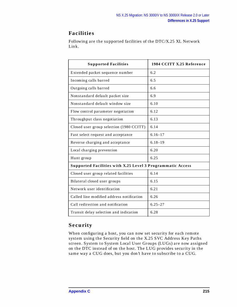
NS X.25 Migration: NS 3000/V to NS 3000/iX Release 2.0 or LaterDifferences in X.25 Support
FacilitiesFollowing are the supported facilities of the DTC/X.25 XL NetworkLink.
SecurityWhen configuring a host, you can now set security for each remotesystem using the Security field on the X.25 SVC Address Key Pathsscreen. System to System Local User Groups (LUGs) are now assignedon the DTC instead of on the host. The LUG provides security in thesame way a CUG does, but you don’t have to subscribe to a CUG.
Supported Facilities 1984 CCITT X.25 Reference
Extended packet sequence number 6.2
Incoming calls barred 6.5
Outgoing calls barred 6.6
Nonstandard default packet size 6.9
Nonstandard default window size 6.10
Flow control parameter negotiation 6.12
Throughput class negotiation 6.13
Closed user group selection (1980 CCITT) 6.14
Fast select request and acceptance 6.16–17
Reverse charging and acceptance 6.18–19
Local charging prevention 6.20
Hunt group 6.25
Supported Facilities with X.25 Level 3 Programmatic Access
Closed user group related facilities 6.14
Bilateral closed user groups 6.15
Network user identification 6.21
Called line modified address notification 6.26
Call redirection and notification 6.25–27
Transit delay selection and indication 6.28
Appendix C 215

NS X.25 Migration: NS 3000/V to NS 3000/iX Release 2.0 or LaterDifferences in X.25 Support
Pad SupportFor complete information on migrating PAD support from NS 3000/V toNS 3000/iX Release 2.0 or later, refer to Appendix E, “NS X.25Migration: NS 3000/V PAD Access to NS 3000/iX Release 2.0 or Later.”
216 Appendix C
NS X.25 Migration: NS 3000/V to NS 3000/iX Release 2.0 or LaterTo Convert NS 3000/V Files to NS 3000/iX Release 2.0 or Later
To Convert NS 3000/V Files to NS 3000/iXRelease 2.0 or LaterThis conversion procedure can be used with NS 3000/V NMCONFIG andNSCONF files for version V-delta 3 or later.
The procedures that follow are for updating (migrating) configurationfiles from a node running NS X.25 3000/V Link to a node that will berunning NS 3000/iX release 2.0 or later. As mentioned, this appendixdoes not apply if an MPE V based node is being used as an X.25 serverfor NS 3000/XL based machines. When updating a node running NSX.25 3000/V Link, all NS 3000/V LAN, Point-to-Point, or NRJE as wellas X.25 information will be updated to work with iX 2.0.
NOTE If you are migrating a configuration file from any MPE V based nodeacting as an X.25 server for NS 3000/XL based machines (including theNS X.25 3000/XL Server product) to an NS 3000/iX node that will berunning NS 3000/iX release 2.0 or later, see Appendix D, “NS X.25Migration: NS 3000/V and NS 3000/XL Release 1.X to iX Release 2.0 orlater.” In that case, you would be merging the server’s NS 3000/Vconfiguration file with an existing NS 3000/XL 1.X configuration file.Furthermore, only X.25 information would be updated (not, LAN,NRJE, or Point-to-Point). The procedures that follow assume that thereis no existing NS 3000/XL NMCONFIG file.
To Delete Secondary NIs (NS/iX Rel. 2.2 or later)If you are migrating from NS X.25 3000/V (release V delta 7 or later) toNS 3000/iX release 2.2 or later, make a backup copy of your NS 3000/VNSCONF file. To migrate to NS 3000/iX release 2.2 or later, you mustdelete the secondary NIs in the NS 3000/V NSCONF file before you useNMMGRVER to convert it.
Appendix C 217
NS X.25 Migration: NS 3000/V to NS 3000/iX Release 2.0 or LaterTo Save NS 3000/V X.25 Parameters
To Save NS 3000/V X.25 ParametersMake a list of the following NS 3000/V parameters that must bere-entered on the DTC.
• VC Assignment from the NS 3000/V screen with the path:
@NETXPORT.NI.niname.PROTOCOL.X25.VCSPEC
• X.25 Network type and Flow Control parms from the NS 3000/Vscreen with the path:
@NETXPORT.NI.niname.PROTOCOL.X25.VCSPEC. FLOWCNTL
• L.U.G. Incoming Calls from the NS 3000/V screen with the path:
@NETXPORT.NI.niname.PROTOCOL.X25.LUGSPEC. INLUG
• L.U.G. Outgoing Calls from the NS 3000/V screen with the path:
@NETXPORT.NI.niname.PROTOCOL.X25.LUGSPEC. OUTLUG
218 Appendix C

NS X.25 Migration: NS 3000/V to NS 3000/iX Release 2.0 or LaterTo Copy NS 3000/V Configuration Files to NS 3000/iX System
To Copy NS 3000/V Configuration Files toNS 3000/iX SystemRestore the NS 3000/V configuration files to the NS 3000/iX system.Name the NS 3000/V files with the same names they had on theNS 3000/V node, that is, NMCONFIG.PUB.SYS, and if present,NSCONF.PUB.SYS.
Remember: This procedure assumes that there is no configuration fileon the NS 3000/iX node yet.
Appendix C 219
NS X.25 Migration: NS 3000/V to NS 3000/iX Release 2.0 or LaterTo Use NMMGRVER
To Use NMMGRVERTo use the NMMGRVER utility to convert your NS 3000/Vconfiguration file to NS 3000/iX release 2.0 or later, proceed as follows:
Step 1. At the MPE/iX prompt, type: NMMGRVER.PUB.SYS
Step 2. Do either steps a through c or steps d through g.
If your NS 3000/V node had only an NMCONFIG file (but no NSCONFfiles), follow the instructions in steps a through c.
a. To convert the NMCONFIG file enter the file name:NMCONFIG.PUB.SYS.
b. Enter Y to proceed when prompted.
c. Select type 2 for NMCONFIGtype file. The converted file will be savedwith the file name you entered. In this case it isNMCONFIG.PUB.SYS. This is the only filename that the node willrecognize as its configuration file.
If your NS 3000/V node had one or more NSCONF files, follow theinstructions in steps d through g.
d. Merge your NS 3000/V NSCONF file with the NS 3000/V NMCONFIGfile, and convert it for use with NS 3000/iX release 2.0 or later byentering a file name, for example: NSCONF1.PUB.SYS.
e. Enter Y to proceed when prompted.
f. Select type 1 for NSCONF type file. NMMGRVER will merge thecontents of the existing NMCONFIG file with the NSCONF file youspecified. It will be saved in the NSCONF file you specified. In thisexample, NSCONF1.
g. If you converted more than one NSCONFfile, decide which one will bethe network configuration you want on the NS 3000/iX system.Rename the file to NMCONFIG.PUB.SYS.
To Update X.25 XL System Access ParametersOn the NS 3000/iX host, use NMMGR to change the followingparameters to provide X.25 XL System Access:
1. If migrating from any NS 3000/V release before release V delta 7,modify the screen at path @NETXPORT.NI.niname.PROTOCOL.X25tochange the inactivity timer from minutes to seconds.
2. On the screen with the path @LINK, verify that the DTSLINK isdefined.
3. On the screen with the path @LINK.DTSLINK, verify that thephysical path is correctly defined.
220 Appendix C
NS X.25 Migration: NS 3000/V to NS 3000/iX Release 2.0 or LaterTo Use NMMGRVER
4. On the screen with the path @LINK, add the LINK name and Type(X25) of the X25 link. Note: to migrate to NS 3000/iX release 2.2or later, repeat this step and steps 5 through 7 for eachDTC/X.25 Network Access card.
5. On the screen with the path @LINK. linkname, where the LINK nameis the one added in the previous step, add the DTC Node name andcard number for the DTC/X.25 Network Access card.
6. On the screen with the path @NETXPORT.NI.niname.LINK , add theLINK name entered in Step 4.
7. On the screen with the path @NETXPORT.NI.niname.LINK. linkname,answer yes or no; then, press the Update key.
To Save X.25 XL System Access Parameters on theHostMake a list of the following X.25 XL System Access Parameters on thehost that must be re-entered on the DTC.
• Local Node Name.
• Link Name (the X25 link, not the DTSLINK).
• DTC Node Name.
• DTC Card Number.
• X.25 User Facility Set Parameters.
To Add Other Link Types as NeededFor LAN and Point-to-Point link types, run NMMGR and add thephysical paths. See sections of this manual for the correct values to beentered for the physical path.
To Verify DTS Configuration on the HostIf the datacommunications and terminal subsystem (DTS) has not beenconfigured, configure the DTS parameters on the host according to therequirements of your network. For more information, refer to GettingStarted with the DTC and Configuring Systems for Terminals, Printers,and Other Serial Devices if you are using PC-based networkmanagement. Refer to Configuring and Managing Host-Based X.25Links if you are using host-based network management.
Appendix C 221

NS X.25 Migration: NS 3000/V to NS 3000/iX Release 2.0 or LaterTo Configure the DTC
To Configure the DTCIf you are using PC-based network management, configure the DTC byusing the OpenView DTC Manager at your OpenView WindowsWorkstation. For full details, see Using the OpenView DTC Manager.
If you are using host-based network management, configure the DTCusing NMMGR. For full details, see Configuring and ManagingHost-Based X.25 Links.
222 Appendix C
D NS X.25 Migration: NS 3000/V andNS 3000/XL Release 1.X to iX
Release 2.0 or later
This Appendix tells how to use the NMMGRVER utility to migrate aconfiguration file from any MPE V based node acting as an X.25 serverfor NS 3000/XL based machines (including the NS X.25 3000/XL Serverproduct) to an NS 3000/iX node that will be running NS 3000/iXrelease 2.0 or later. This appendix assumes that you want to move theX.25 configuration from the MPE V-based X.25 server to an existingNS 3000/XL node and then upgrade it to NS 3000/iX 2.0.
This appendix does not apply if the MPE V node you want to migratefrom is not acting as an X.25 server for NS 3000/XL based machines.Refer to the following appendixes depending on which X.25 networkproducts you currently have:
• For migrating a node’s configuration file from NS 3000/XL releases1.0, 1.1, or 1.2 to NS 3000/iX release 2.0 or later, refer to Appendix B,“NS X.25 Migration: NS 3000/XL Releases 1.0, 1.1, or 1.2 toNS 3000/iX Release 2.0 or Later.”
• For migrating a configuration file from a node running NS X.253000/V Link to a node that will be running NS 3000/iX release 2.0 orlater, refer to Appendix C, “NS X.25 Migration: NS 3000/V toNS 3000/iX Release 2.0 or Later.” This appendix does not apply if theMPE V node you want to migrate from is acting as an X.25 server forNS 3000/XL based machines.
• For migrating a configuration file from a node running NS 3000/VPAD to an NS 3000/iX node that will be running NS 3000/iXrelease 2.0 or later, refer to Appendix E, “NS X.25 Migration:NS 3000/V PAD Access to NS 3000/iX Release 2.0 or Later.”
This appendix also provides an overview of the differences betweennetworking functionality on an MPE V and an MPE/iX system you needto consider for migration.
223
NS X.25 Migration: NS 3000/V and NS 3000/XL Release 1.X to iX Release 2.0 or laterDifferences Between NS 3000/V and NS 3000/iX
Differences Between NS 3000/V andNS 3000/iXThe following paragraphs summarize differences between NS 3000/Vand NS 3000/iX. Make sure that you account for these differences thatcould affect your network when migrating to NS 3000/iX. For systemmigration issues, refer to the MPE/iX Migration series for moreinformation.
Differences in HardwareSome NS 3000/V hardware components are not part of an NS 3000/iXnetwork, such as the ATP for terminal connections, and the INP fornetwork links.
On an NS 3000/iX network, the DTC provides connections for local orremote terminals and serial printers. The DTC also provides MPE/iXaccess to X.25 through a DTC/X.25 Network Access card. TheDistributed Terminal Subsystem (DTS) LANIC on the MPE/iX host isused for system-to-system X.25 connectivity.
Unsupported Network ConnectionsBefore migrating your network, identify any unsupported networkconnections. The network connections that are not supported onNS 3000/iX networks are as follows:
• Manual-dial modems.
• Asynchronous SERIAL Network Link and bisynchronous link-levelprotocol. To ease migration, you can convert Asynchronous SERIALnetwork links to the NS 3000/V Point-to-Point links which can beconverted to NS 3000/iX. Point-to-Point links use the LAP-Bprotocol.
• Connections to DS/3000 nodes. DS network services are notsupported on NS 3000/iX. If DS/3000 nodes are part of an existingnetwork, either migrate them to NS 3000/V or maintain NS 3000/Vconnections to the DS/3000 nodes.
Differences in Configuration of Terminals andPrintersOn NS 3000/V networks, the SYSDUMP program is used to perform I/Oconfiguration which includes configuring terminals, printers, and otherI/O devices and drivers. On NS 3000/iX, terminals and serial printersare configured on the host (using NMMGR) and, if you are usingPC-based network management, on the OpenView Windows
224 Appendix D

NS X.25 Migration: NS 3000/V and NS 3000/XL Release 1.X to iX Release 2.0 or laterDifferences Between NS 3000/V and NS 3000/iX
Workstation (using the OpenView DTC Manager software). For moreinformation on configuration using your OpenView WindowsWorkstation, read Using the OpenView DTC Manager.
PAD devices on NS 3000/V are configured (using NMMGR) as part ofthe X.25 network configuration. On NS 3000/iX with PC-based networkmanagement, PAD devices are configured both on the host (usingNMMGR) and on the OpenView Windows Workstation (using theOpenView DTC Manager software). (With host-based networkmanagement, PAD devices are also configured using NMMGR.)
Differences in Configuration FilesNS 3000/V network configuration files are separated into two files, theNMCONFIG file, which contains link information, and the NSCONF file,which contains the transport configuration and other subsystems youhave purchased such as SNA.
NS 3000/iX systems have a single NMCONFIG.PUB.SYS file thatcontains information for the network transport, for NetIPC andlink-level logging, and also for the Datacommunications and TerminalSubsystem (DTS). NMCONFIG.PUB.SYS also contains information forany other subsystems you have purchased such as SNA.
Differences in Network ServicesDifferences in the support of network services between NS 3000/V andNS 3000/iX can affect applications that users may currently be runningon the NS 3000/V network. These differences are:
• NS 3000/iX supports PTOP for HPDESK only. Network users whoare running PTOP programs will need to convert them toNetIPC/RPM programs before running them on an NS 3000/iXnetwork. Refer to the NetIPC 3000/XL Programmer’s ReferenceManual and the Using NS 3000/iX Network Services for moreinformation.
• Nowait I/O RFA is not available with NS 3000/iX. Privileged modeprograms that use nowait I/O Remote File Access over an NS 3000/Vnetwork will need to be modified before they can be run on anNS 3000/iX network. Refer to Using NS 3000/iX Network Servicesfor more information.
To Obtain Device Status InformationOn MPE V systems, the SHOWCOMcommand returns status informationabout communication devices such as Local Area Network InterfaceControllers(LANICs). On NS 3000/iX systems, this information isavailable with the LINKCONTROL...;STATUS command.
Appendix D 225

NS X.25 Migration: NS 3000/V and NS 3000/XL Release 1.X to iX Release 2.0 or laterDifferences in X.25 Support
Differences in X.25 SupportThere are differences in X.25 support between NS 3000/V andNS 3000/iX which need to be considered when you migrate as describedin the following paragraphs.
1980 vs. 1984 CCITTNS 3000/V supports CCITT 1980 and NS 3000/XL supports both 1980and 1984.
General Level 3 DifferencesIn MPE V X.25, a Reset is sent to initialize or clear a PermanentVirtual Circuit. In MPE/iX X.25, a Reset is not sent to initialize or cleara Permanent Virtual Circuit.
MPE V X.25 has a timeout on an interrupt collision. MPE/iX X.25 doesnot.
Level 3 Access with NetIPCIn addition to the X.25 features supported on NS 3000/V, NetIPC3000/XL provides the following CCITT 1984 features:
• Fast select.
• The capability of modifying and reading the facility field in callpackets.
• A new option in IPCDEST (called the destination network addressoption) allows you to directly specify an X.25 address or PVC numberinstead of a remote node name. See the NetIPC 3000/XLProgrammers Reference Manual for more information. If using thisfeature, you can configure POOL as an X.25 Address Key with itssecurity option set to “O” (outbound) in the X.25 SVC Address KeyPaths screen to allow outbound calls to any destination address.
• IPCCONTROLrequest 12, reason for error or event, on NS 3000/Vcan return 14 (network shutdown), 15 (restart sent by localnetwork), 16 (level 2 failure), 17 (restart sent by local protocolmodule), and 18 (restart packet received). IPCCONTROL onNS 3000/XL only returns 10 (Clear), 11 (Reset), or 12 (Interrupt).
• In NS 3000/V, IPCSHUTDOWN does not complete until a clearconfirmation arrives. In NS3 000/XL, IPCSHUTDOWN completesimmediately.
• In NS 3000/V, IPCCREATE requires that the network name bepadded with nulls. In NS 3000/XL, IPCCREATErequires the networkname be padded with blanks.
226 Appendix D
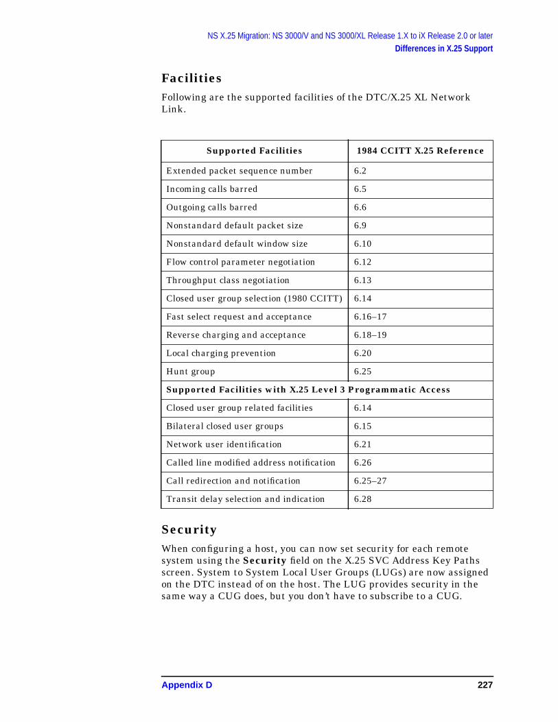
NS X.25 Migration: NS 3000/V and NS 3000/XL Release 1.X to iX Release 2.0 or laterDifferences in X.25 Support
FacilitiesFollowing are the supported facilities of the DTC/X.25 XL NetworkLink.
SecurityWhen configuring a host, you can now set security for each remotesystem using the Security field on the X.25 SVC Address Key Pathsscreen. System to System Local User Groups (LUGs) are now assignedon the DTC instead of on the host. The LUG provides security in thesame way a CUG does, but you don’t have to subscribe to a CUG.
Supported Facilities 1984 CCITT X.25 Reference
Extended packet sequence number 6.2
Incoming calls barred 6.5
Outgoing calls barred 6.6
Nonstandard default packet size 6.9
Nonstandard default window size 6.10
Flow control parameter negotiation 6.12
Throughput class negotiation 6.13
Closed user group selection (1980 CCITT) 6.14
Fast select request and acceptance 6.16–17
Reverse charging and acceptance 6.18–19
Local charging prevention 6.20
Hunt group 6.25
Supported Facilities with X.25 Level 3 Programmatic Access
Closed user group related facilities 6.14
Bilateral closed user groups 6.15
Network user identification 6.21
Called line modified address notification 6.26
Call redirection and notification 6.25–27
Transit delay selection and indication 6.28
Appendix D 227

NS X.25 Migration: NS 3000/V and NS 3000/XL Release 1.X to iX Release 2.0 or laterDifferences in X.25 Support
PAD SupportFor complete information on migrating PAD support from NS 3000/V toNS 3000/iX Release 2.0, refer to Appendix E, “NS X.25 Migration:NS 3000/V PAD Access to NS 3000/iX Release 2.0 or Later.”
228 Appendix D

NS X.25 Migration: NS 3000/V and NS 3000/XL Release 1.X to iX Release 2.0 or laterTo Convert MPE V-Based Server Files to NS 3000/iX Release 2.0 or later
To Convert MPE V-Based Server Files toNS 3000/iX Release 2.0 or laterThe conversion procedure that follows is for moving an X.25configuration from an MPE V-based X.25 server (including the NS X.253000/XL Server product) to an existing NS 3000/XL node and thenupgrading it to NS 3000/iX 2.0.
Only the X.25 information will be taken from the MPE V-based X.25server’s NSCONF configuration file. LAN, Point-to-Point, or NRJEinformation will be updated from your existing NS 3000/XL NMCONFIGfile. After using NMMGRVER, you will then have to perform someadditional configuration steps that are described in the remainder ofthis Appendix.
Appendix D 229
NS X.25 Migration: NS 3000/V and NS 3000/XL Release 1.X to iX Release 2.0 or laterTo Delete Secondary NIs (NS/XL Release 2.2 or later)
To Delete Secondary NIs (NS/XL Release 2.2or later)If you are migrating from NS X.25 3000/V (release V delta 7 or later) toNS 3000/iX release 2.2 or later, make a backup copy of your NS 3000/VNSCONF file. To migrate to NS 3000/iX release 2.2 or later, you mustdelete the secondary NIs in the NS 3000/V NSCONF file before you useNMMGRVER to convert it.
230 Appendix D
NS X.25 Migration: NS 3000/V and NS 3000/XL Release 1.X to iX Release 2.0 or laterTo Save NS 3000/V X.25 Parameters
To Save NS 3000/V X.25 ParametersMake a list of the following NS 3000/V parameters that must bere-entered on the DTC.
• VC Assignment from the NS 3000/V screen with the path:@NETXPORT.NI.niname.PROTOCOL.X25.VCSPEC
• X.25 Network type and Flow Control parms from the NS 3000/Vscreen with the path:@NETXPORT.NI.niname.PROTOCOL.X25.VCSPEC. FLOWCNTL
• L.U.G. Incoming Calls from the NS 3000/V screen with the path:@NETXPORT.NI.niname.PROTOCOL.X25.LUGSPEC.INLUG
• L.U.G. Outgoing Calls from the NS 3000/V screen with the path:@NETXPORT.NI.niname.PROTOCOL.X25.LUGSPEC.OUTLUG
Appendix D 231
NS X.25 Migration: NS 3000/V and NS 3000/XL Release 1.X to iX Release 2.0 or laterTo Copy NS 3000/V Configuration Files to NS 3000/iX System
To Copy NS 3000/V Configuration Files toNS 3000/iX SystemRestore the NS 3000/V NSCONF configuration file to the NS 3000/iXsystem. Name the NS 3000/V file with the same name it had on theNS 3000/V node, that is, NSCONF.PUB.SYS.
Remember: This procedure assumes that there already is anNS 3000/XL 1.X NMCONFIG.PUB.SYS configuration file on theNS 3000/iX node. Do not overwrite it with the NS 3000/V version!
232 Appendix D
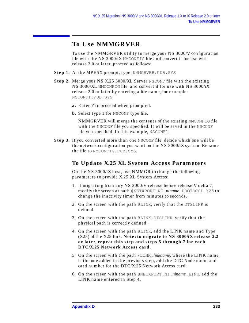
NS X.25 Migration: NS 3000/V and NS 3000/XL Release 1.X to iX Release 2.0 or laterTo Use NMMGRVER
To Use NMMGRVERTo use the NMMGRVER utility to merge your NS 3000/V configurationfile with the NS 3000/iX NMCONFIG file and convert it for use withrelease 2.0 or later, proceed as follows:
Step 1. At the MPE/iX prompt, type: NMMGRVER.PUB.SYS
Step 2. Merge your NS X.25 3000/XL Server NSCONF file with the existingNS 3000/XL NMCONFIG file, and convert it for use with NS 3000/iXrelease 2.0 or later by entering a file name, for example:NSCONF1.PUB.SYS
a. Enter Y to proceed when prompted.
b. Select type 1 for NSCONF type file.
NMMGRVER will merge the contents of the existing NMCONFIG filewith the NSCONF file you specified. It will be saved in the NSCONFfile you specified. In this example, NSCONF1.
Step 3. If you converted more than one NSCONF file, decide which one will bethe network configuration you want on the NS 3000/iX system. Renamethe file to NMCONFIG.PUB.SYS.
To Update X.25 XL System Access ParametersOn the NS 3000/iX host, use NMMGR to change the followingparameters to provide X.25 XL System Access:
1. If migrating from any NS 3000/V release before release V delta 7,modify the screen at path @NETXPORT.NI.niname.PROTOCOL.X25tochange the inactivity timer from minutes to seconds.
2. On the screen with the path @LINK, verify that the DTSLINK isdefined.
3. On the screen with the path @LINK.DTSLINK, verify that thephysical path is correctly defined.
4. On the screen with the path @LINK, add the LINK name and Type(X25) of the X25 link. Note: to migrate to NS 3000/iX release 2.2or later, repeat this step and steps 5 through 7 for eachDTC/X.25 Network Access card.
5. On the screen with the path @LINK. linkname, where the LINK nameis the one added in the previous step, add the DTC Node name andcard number for the DTC/X.25 Network Access card.
6. On the screen with the path @NETXPORT.NI.niname.LINK , add theLINK name entered in Step 4.
Appendix D 233
NS X.25 Migration: NS 3000/V and NS 3000/XL Release 1.X to iX Release 2.0 or laterTo Use NMMGRVER
7. On the screen with the path @NETXPORT.NI.niname.LINK. linkname,answer yes or no; then, press the Update key.
To Save X.25 XL System Access Parameters on theHostMake a list of the following X.25 XL System Access Parameters on thehost that must be re-entered on the DTC.
• Local Node Name.
• Link Name (the X25 link, not the DTSLINK).
• DTC Node Name.
• DTC Card Number.
• X.25 User Facility Set Parameters.
To Add Other Link Types as NeededFor LAN and Point-to-Point link types, run NMMGR and add thephysical paths. See sections of this manual for the correct values to beentered for the physical path.
To Verify DTS Configuration on the HostIf the datacommunications and terminal subsystem (DTS) has not beenconfigured, configure the DTS parameters on the host according to therequirements of your network. For more information, refer to GettingStarted with the DTC and Configuring Systems for Terminals, Printers,and Other Serial Devices if you are using PC-based networkmanagement. Refer to Configuring and Managing Host-Based X.25Links if you are using host-based network management.
234 Appendix D
NS X.25 Migration: NS 3000/V and NS 3000/XL Release 1.X to iX Release 2.0 or laterTo Configure the DTC
To Configure the DTCIf you are using PC-based network management, configure the DTC byusing the OpenView DTC Manager at your OpenView WindowsWorkstation. For full details, see Using the OpenView DTC Manager.
If you are using host-based network management, configure the DTCusing NMMGR. For full details, see Configuring and ManagingHost-Based X.25 Links.
Appendix D 235

NS X.25 Migration: NS 3000/V and NS 3000/XL Release 1.X to iX Release 2.0 or laterTo Configure the DTC
236 Appendix D
Glossary
A
access port A special interfacecard in the system cabinetthrough which the system consoleis connected.
address A numerical identifierdefined and used by a particularprotocol and associated softwareto distinguish one node fromanother.
address key See X.25 addresskey.
address resolution In NSnetworks, the mapping of nodenames to IP addresses and themapping of IP addresses tosubnet addresses.
address resolution protocol
ARP. A protocol used by LANlinks with Ethernet enabled thatprovides a means of exchangingaddressing information betweenEthernet nodes.
adjacent A node on apoint-to-point network that isconnected to another node by asingle link with no interveningnodes.
ARP See address resolutionprotocol.
ASCII American NationalStandard Code for InformationInterchange. A character setusing 7-bit code used forinformation interchange amongdata processing and data
communications systems. TheAmerican implementation ofInternational Alphabet No. 5.
asynchronous Term used todescribe a device’s mode ofoperation whereby a sequence ofoperations are executedirrespective of time coincidencewith any event. Devices that aredirectly accessible by people (forexample, terminal keyboards)operate in this manner.
attachment unit interface Thecable that runs between eachnode (host, DTC, or other device)and the Medium AttachmentUnit (MAU) that connects it tothe LAN in a ThickLANconfiguration.
AUI See attachment unitinterface.
autodial A dial link in which theremote node’s telephone numberis automatically dialed by amodem or other device with thiscapability.
B
backbone LAN A thick LANcable conforming to the IEEE802.3 Type 10 BASE 5 standard.
back-to-back configuration ADTC configuration whereby MPEusers connected to one DTC cancommunicate with a non-MPE/iXsystem connected to another DTCvia the LAN. (See also LocalSwitching)
Glossary 243
Glossary
backup configuration file Afile that contains a copy of theinformation contained in theconfiguration file. The backup file,called NMCBACK.group.accountby default, is updated each timethe configuration file issuccessfully validated.
banner A welcome messagedisplayed on your screen. On thelocal OpenView workstation abanner appears when a remoteconnection is established with theOpenView DTC Manager. Abanner also can appear when youlog on to MPE.
baud Measure of the speed atwhich information travelsbetween devices, most commonlyused in reference to terminalspeed settings. Baud representssignal events per second. Whenone bit represents each signalchange, baud is the same as “bitsper second”.
binary mode Data transferscheme in which no specialcharacter processing isperformed. All characters areconsidered to be data and arepassed through with no controlactions being taken.
bit Binary digit. A unit ofinformation that designates oneof two possible states, which arerepresented by either 1 or 0.
block mode Terminal processingmode in which groups, or “blocks,”of data are transmitted all atonce.
BNC T-Connector Connectorused to connect a computer or acomponent such as a DTC to theLAN in a ThinLAN configuration.
boundry See networkboundary.
bps Bits per second. The numberof bits passing a point per second.
broadcast Communicationmethod of sending a message toall devices on a linksimultaneously.
byte A sequence of eightconsecutive bits operated on as aunit.
C
call In X.25, a call is an attemptto set up communication betweentwo DTEs using a virtual circuit.Also known as a virtual call.
call collision A conflict thatoccurs at a DTE/DCE interfacewhen there is a simultaneousattempt by the DTE and DCE toset up a call using the samelogical channel identifier.
called address When a nodesends out a call request packet,the packet contains the address ofthe destination node. The addressof the destination node is thecalled address.
calling address When a nodereceives an incoming call packet,the packet contains the address of
244 Glossary
Glossary
the sending node. The address ofthe sending node is the callingaddress.
carrier A continuous wave thatis modulated by an informationbearing signal.
catenet See internetwork.
CCITT Consultative Committeefor International Telephony andTelegraphy. An internationalorganization of communicationcarriers, especially governmenttelephone monopolies, responsiblefor developing telecommunicationstandards by makingrecommendations. No carrier isrequired to adhere to a CCITTrecommendation, although mostdo so in their own interest.
CIB The channel input/outputbus in the backplane of anHP 3000.
circuit-switching network Atype of data communicationsnetwork wherein a physical andexclusive link is maintainedbetween two communicatingdevices for the call duration. Anall-digital, circuit-switchingnetwork is often referred to as anX.21 network.
closed user group An X.25 userfacility that allowscommunication to and from apre-specified group of users andno one else.
compatibility mode Processingmode on HP 3000 Series 900computers that allows
applications written for MPEV/E-based systems to be portedand run without changes orrecompilation.
computer network A group ofcomputer systems connected insuch a way that they canexchange information and shareresources.
configuration 1) The way inwhich computer equipment isphysically interconnected and setup to operate as a system.
2) The layout of the computersystem, including the MPE table,memory, and buffer sizes, thattells which peripheral devices are(or can be) connected to thecomputer and how they can beaccessed.
3) The process of defining thecharacteristics of a network insoftware. For MPE/iX-basedcomputers, the operating systemsare configured through use of theSYSGEN utility. Next, thedistributed terminal subsystem(DTS) link is configured by usingNMMGR (running on the host)and may, in addition, beconfigured using the OpenViewDTC Manager software (runningon the OpenView WindowsWorkstation) depending on thetype of network management youuse. If any of the NS link productsare installed on the system,network configuration isaccomplished through use of
Glossary 245
Glossary
NMMGR and, if PC-based X.25connections are required, throughthe OpenView DTC Manager.
configuration file Theconfiguration file, which youcreate and update using theNMMGR utility, contains:
1) the information that thenetwork needs in order tooperate.
2) Information necessary forlink-level and NetIPC logging.
3) Information required toconnect terminals and printers tothe system through one or moreDTC.
The only file name that thesystem recognizes as theconfiguration file isNMCONFIG.PUB.SYS.
control-X echo Threeexclamation marks (!!! ) outputto the terminal screen when thecancel character (normally[CTRL]-X ) is entered.
control-Y trap User-writtenprocedure to which control ispassed when the subsystem breakcharacter (normally [CTRL]-Y ) isentered during execution of aprogram with subsystem breakenabled.
cross-validate The process ofassuring that informationcontained in two locations isconsistent where it is imperativethat it be consistent. For example,an automatic cross-validation
occurs when you enter SYSGENto assure that informationcontained in NMCONFIG.PUB.SYSagrees with system configurationdata.
CSMA/CD Carrier SenseMultiple Access with CollisionDetect, transmission accessmethod used by the IEEE 802.3LAN standard.;
CSN See circuit-switchingnetwork.
CTB The cache transfer bus inthe backplane of an HP 3000.
CUG See closed user group.
D
data Basic elements ofinformation that can be processedor produced by a computer.
datacommunications andTerminal Controller See DTC.
data overrun Transmitted datathat is sent faster than theequipment on the receiving end iscapable of receiving it. Theresulting overflow data is lost. Seealso flow control.
Datapac The national publicPSN of Canada.
Datex-P The national publicPSN of West Germany.
D bit Delivery confirmation bit.Used in the X.25 protocol, thesetting of the D bit in DATApackets indicates whether
246 Glossary
Glossary
delivery acknowledgment of thepacket is required from the localDCE or from the remote DTE. Ittherefore allows the choicebetween local and end-to-endacknowledgment.
DCE Data circuit-terminatingequipment. The interfacingequipment required in order tointerface to data terminalequipment (DTE) and itstransmission circuit. Synonyms:data communications equipment,dataset.
DDX The national public PSN ofJapan.
dedicated printer A printerthat can be used by only one hoston the LAN; the one specified inthe Destination Node Name inthat printer’s configurationscreen.
default gateway One (and onlyone) gateway accessible by asystem may be designated as adefault gateway. The network willthen send any transmittedmessages for which it is unable tolocate a destination throughnormal means to the defaultgateway in a final effort todetermine a transmission route.
demodulation The process bywhich the information-bearingsignal is retrieved from amodulated carrier wave. Theinverse of modulation.
destination node name In DTSconfiguration, it is either 1) thename of a host that a user can beconnected to by default (ifswitching is not enabled for thatuser, or if automatic modemconnection is enabled), or 2) thename of the only host that canaccess a dedicated printer.
device class A collection ofdevices that have someuser-defined relation. Deviceclasses are assigned through useof the NMMGR configurationutility.
device-dependentcharacteristic A filespecification for whichmodifications are restrictedbecause of the type of device onwhich the file is opened. Forexample, data directed toterminals must have a blockingfactor of one.
device driver Software modulethat controls a specific type ofinput/output device includingNS 3000/iX links.
devicefile A file being input to oroutput from any peripheral deviceexcept a disk. MPE allowsoperations to be performed on thedevice itself as if it were a file.
device independence Acharacteristic of the operatingsystem that allows users toselectively redirect input/outputfrom a program, session, or jobwithout regard to the nature ofthe device.
Glossary 247

Glossary
device name See PAD name.
Dial ID protocol A proprietaryHewlett-Packard protocol thatprovides security checking andaddress exchange for dial links.
dial link A connection madethrough public telephone lines.
direct-connect device
Asynchronous device that isconnected directly to a DTCthrough an RS-232-C or RS-422cable, with no interveningcommunications equipment. Alsoreferred to as a “local connection.”
direct connection A leased line,private line, or othernon-switched link in a network.
direct dial A dial link throughwhich only one remote node canbe reached.
direct-path branching heprocess of directly accessing anyscreen in NMMGR by enteringpath names in the Command:field. The path name must bepreceded by an at sign (@).
domain name A namedesignated for a system inARPANET standard format. Thisname can be used by other nodeson the network to access the hostfor which it is configured.
download The process of loadingoperating code and configurationfiles into the DTC’s memory. TheDTC is downloaded by the hostcomputer for LANs using
host-based network management,and by the PC for DTCs managedby the OpenView DTC Manager.
driver See device driver.
DTC Datacommunications andTerminal Controller. The DTC isa hardware device, configured asa node on a LAN, that enablesasynchronous devices to accessHP 3000 Series 900 computers.Terminals can either be directlyconnected to the DTC, or they canbe remotely connected throughmodem or through a PacketAssembler Disassembler (PAD).
DTC identifier An identifierused only within NMMGR todefine the branch of theconfiguration file containinginformation about a particularDTC. The identifier must beginwith a letter and can be up toeight characters long.
DTC Manager See OpenViewDTC Manager.
DTC node name Unique nameused to identify a DTC on theLAN. Node name format isnodename.domain.organization,with each of the three partshaving up to 16 characters andbeginning with either a letter or adigit.
DTC station address (802.3address) 2-digit hexadecimalnumber used to identify the DTCas a node belonging to thenetwork configuration. Also calledthe LAN address.
248 Glossary
Glossary
DTC switching A facilityenabling terminal users to selectany host system that they want toconnect to. DTC switching isavailable only when theOpenView DTC Manager is usedfor network management.
DTC/X.25 Network Access heX.25 software that resides on theDatacommunications andTerminal Controller (DTC). Toconfigure access to an X.25network, you must configure twosoftware components: the X.25 iXSystem Access (residing on theHP 3000 host), and the DTC/X.25Network Access. DTC/X.25Network Access is configuredthrough use of the OpenViewDTC Manager software forsystems using PC-based networkmanagement or through NMMGRfor systems using host-basednetwork management.
DTC/X25 Network AccessCard This is the hardware cardand channel adapter thatprovides X.25 Network Access. Itresides in theDatacommunications andTerminal Controller (DTC).
DTC/X.25 iX Network Link
Software and hardware thatprovides access to private andpublic X.25 networks. The X.25 iXSystem Access software resideson an HP 3000 host and isconfigured through use ofNMMGR.
DTE Data terminal equipment.Equipment that converts userinformation intodata-transmission signals orreconverts received data signalsinto user information. Dataterminal equipment operates inconjunction with datacircuit-terminating equipment.
DTS Distributed terminalsubsystem. This consists of all theDatacommunications andTerminal Controllers (DTCs) on aLAN, their LANIC cards(attached to the host), the LANcable, and the host and DTCsoftware that controls all relatedDTS hardware.
duplex Transmission methodthat allows two-waycommunication. If both ends ofthe transmission link cantransmit simultaneously, it iscalled full duplex. If only one endcan transmit at a time, it ishalf-duplex transmission.
E
entry priority The ranking thatidentifies the most desirableroute used to reach a givenremote node from a given localnode in a point-to-point network.
environment A session that isestablished on a remote node.
escape from data transfercharacter A character thatallows a user who is connected toa host system through the DTC tobreak that connection and return
Glossary 249
Glossary
to the DTC switching userinterface. The default is [CTRL]-K .This character is used only onnetworks managed by theOpenView Windows Workstation.
escape sequence A sequence ofcharacters beginning with theescape character and followed byone or more other characters,used to convey control directivesto printers, plotters, or terminals.
Ethernet A Local Area Networksystem that uses basebandtransmission at 10 Mbps overcoaxial cable. Ethernet is atrademark of Xerox Corporation.
event log One of three circularfiles stored on the OpenViewworkstation containing lists of allsignificant events reported by theDTCs for which it is the owner;that is, whose operatingsoftware/configuration it hasdownloaded.
extended packet sequencenumbering One of the optionalnetwork subscribed facilities thatprovides packet sequencenumbering using modulo 128. Ifnot subscribed, modulo 8 is used.
F
facility An optional serviceoffered by a packet switchingnetwork’s administration andrequested by the user either atthe time of subscription fornetwork access or at the time acall is made. Also known as userfacility.
facility set A facility set definesthe various X.25 connectionparameters and X.25 facilitiesthat can be negotiated for eachvirtual circuit on a per-call basis.
fast select An optionalpacket-switching network facilityby which user data may betransmitted as part of the controlpackets that establish and clear avirtual connection.
FCS Frame check sequence. Asequence of bits generated byX.25 at level 2 that forms part ofthe frame and guarantees theintegrity of its frame’s content.The FCS is also used by theIEEE802.3 protocol to check thevalidity of frames.
FDDI Fiber Distributed DataInterface. A set of ANSIstandards that define a 100 Mb/stimed token passing protocol LANthat uses fiber optic cable as thetransmission medium. FDDI is aspecification for a high-speedfiber-optic ring network.
file equation Assignmentstatement used to associate a filewith a specific device or type ofdevice during execution of aprogram.
file number Unique numberassociated with a file when thefile is opened. The file number isreturned in the FOPEN orHPFOPEN call used to open thefile. It can be used to access thatfile until the file is closed.
250 Glossary

Glossary
file specification The name andlocation of a file. The fullspecification for a file includes thefile name, group, and account.
file system The part of theoperating system that handlesaccess to input/output devices(including those connectedthrough the DTC), data blocking,buffering, data transfers, anddeblocking.
flow control A means ofregulating the rate at which datatransfer takes place betweendevices to protect against dataoverruns.
flow control negotiation Oneof the network subscribedfacilities, selected at subscriptiontime. This facility allows the flowcontrol parameter to benegotiated at call set-up time, asopposed to having a predefinedvalue.
formal file designator Namethat can be usedprogrammatically or in a fileequation to refer to a file.
FOS Fundamental operatingsystem. The programs, utilities,and subsystems supplied on themaster installation tape thatform the basic core of theoperating system.
full gateway A full gateway is anode that belongs to more thanone network and has one IPaddress for each network. It uses
store and forward to transferpackets between each networkthat it belongs to.
G
gateway A node that connectstwo dissimilar networkarchitectures. A gateway can beeither a single node (full gateway)or two gateway halves.
gateway half A node that worksin conjunction with another nodeon another network to form aninternetwork. The only protocolused by gateway halves is the NSPoint-to-Point 3000/iX Link. Seealso full gateway.
gateway-half link A linkbetween the two nodes of agateway-half pair. Each of the twonodes of a gateway-half pair has aconfigured link (hardwareinterface card) that is used for thegateway half network interface.The NS Point-to-Point 3000/iXLink is the only link that can beused as a gateway-half link.;
gateway-half pair A set of twonodes that are joined by agateway-half link. Each node inthe pair must have agateway-half network interfaceconfigured, using the link.
guided configuration A methodof configuring a node in which asubset of the complete NMMGRinterface is presented anddefaults of configurable valuesare used automatically.
Glossary 251

Glossary
H
handshaking A communicationsprotocol between devices orbetween a device and the CPU.Provides a method of determiningthat each end of acommunications link is ready totransmit or receive data and thattransmission has occurredwithout error.
hop count See internet hopcount and intranet hop count
host-based networkmanagement Method ofmanaging asynchronouscommunications for HP 3000Series 900 computers. All of thecontrol software is configured on asingle host and is downloaded tothe DTCs that are managed bythat host. With host-basedmanagement, there is apermanent relationship betweeneach DTC and the host, andterminal users can access onlythe single system that owns theDTC their terminal is connectedto.
host-based X.25 Themanagement of X.25 networkconnections from a host computer.Host-based X.25 networkconnections are made through aDTC Network Access cardinstalled in a DTC managed bythe host. All configuration isaccomplished using the NMMGRutility. It is not necessary for a PCto be part of the LAN when youare using host-based X.25.
host computer The primary orcontrolling computer on anetwork. The computer on whichthe network control softwareresides. For HP purposes, it mayalso be used to distinguish theHP 3000 Series 900 system (host)from the DTC.
HP block mode Block modetransmission method employedby HP computers where thesystem controls the block modehandshake. When HP block modeis used, the user program neednot concern itself with datatransfer protocol.
HP PPN Hewlett-PackardPrivate Packet Network.Hewlett-Packard’s ownpacket-switching X.25 network,which gives users full control overthe administration and securityof their data communications.
HP TS8 A terminal server thatcan support up to eightasynchronous serial connections.When used in back-to-backconfiguration, users can accessHP 3000 MPE/V systems on it viaa DTC.
I
idle device timeout Timeoutdefined by the Configure: CPUcommand. When the timer lapses,a device connected to the DTCuser interface that is still inactivewill be disconnected.
252 Glossary
Glossary
IEEE 802.3 A standard for abroadcast local area networkpublished by the Institute forElectrical and ElectronicsEngineers (IEEE). This standardis used for both the ThinLAN andThickLAN implementations ofthe LAN.
IEEE 802.3 multicast address
A hexadecimal number thatidentifies a set of nodes. Thisaddress is used for multicastdelivery.
IEEE 802.3 nodal address Aunique hexadecimal number thatidentifies a node on an IEEE802.3 LAN.
IEEE 902.5 A standard for atoken ring network published bythe Institute for Electrical andElectronics Engineers (IEEE).This standard is used for theToken Ring 3000/iX NetworkLink.
initialization string A sequenceof control characters used toinitialize a terminal, printer, orplotter when a connection isestablished from a host on thenetwork.
interactive communications
Processing that allows users toenter commands and data at theterminal and receive animmediate response.
internet hop count Thenumber of full gateways plus thenumber of gateway-half links that
a packet must pass through inmoving from source node todestination.
internet protocol A protocolused to provide routing betweendifferent local networks in aninternetwork, as well as amongnodes in the same local network.The internet protocol correspondsto layer 3, the network layer, ofthe OSI model. See also IPaddress.
internet routing Internetrouting involves all the processesrequired to route a packet from anode on one network to adestination node on anothernetwork.
internetwork Two or morenetworks joined by gateways,bridges, or routers.
intranet communication
Communication that occursbetween nodes in a singlenetwork.
intranet hop count Thenumber of intermediate nodesthat lie between a source anddestination node on the samepoint-to-point network.
intranet routing Intranetrouting involves all the processesrequired to route a packet fromone node in a network to anothernode in the same network.
intrinsic System routineaccessible by user programswhich provides an interface to
Glossary 253
Glossary
operating system resources andfunctions. Intrinsics performcommon tasks such as file accessand device control.
IP See internet protocol.
IP address Internet protocoladdress. An address used by theInternet Protocol to performinternet routing. A complete IPaddress comprises a networkportion and a node portion. Thenetwork portion of the IP addressidentifies a network, and the nodeportion identifies a node withinthe network.
IP subnet mask See subnetmask.
ISO International StandardsOrganization. An internationalfederation of national standardsorganizations involved indeveloping internationalstandards, includingcommunication standards
L
LAN Local Area Network. Acollection of data communicationsystems sharing a common cablewhereby each system cancommunicate directly withanother.
LAN address See stationaddress.
LANIC See Local AreaNetwork Interface Controller.
LANIC physical path Thephysical location (slot number) ofthe LANIC within the SPU.
LANIC self-test A ROM-basedprogram on a LANIC card thattests and reports the status of theLANIC hardware.
LAP Link access protocol. Thedata link protocol specified byolder versions (prior to 1980) ofX.25 at level 2 but still permittedand therefore usable. All newimplementations of X.25 must useLAP-B, and all oldimplementations must migrate toLAP-B at a future date.
LAP-B Link access protocol -balanced. The data link protocolspecified by the 1980 version ofX.25 at level 2 that determinesthe frame exchange procedures.LAP-B must also be used overdirect-connect NS Point-to-Point3000/iX Links.
LCI Logical channel identifier.Local value on a network nodewhich identifies the channel usedto establish a virtual circuit (SVCor PVC) through an X.25network.
ldev See logical devicenumber.
leased line Data-gradetelephone line leased directly to asubscriber and allocatedspecifically for the subscriber’sneeds.
254 Glossary
Glossary
line speed Speed at which datais transferred over a specificphysical link (usually measuredin bits or kilobits per second).
link name The name thatrepresents a hardware interfacecard. The link name can containas many as eight characters. Allcharacters except the first can bealphanumeric; the first charactermust be alphabetic.
Local Area Network InterfaceController (LANIC) Ahardware card that fits into thebackplane of the HP 3000Series 900 computer and providesa physical layer interface for localarea networks.
local connection See directconnection.
local node The computer thatyou are configuring or that youare logged on to.
local switching Feature of theDTC which permits back-to-backconfiguration (for connections toan HP 3000 MPE/V host), usingtwo ports of the same DTC.
local user group A list definedfor a particular DTC and cardthat specifies which remote nodesthis DTC can send data to andalso which remote nodes this DTCcan receive data from. (See alsoClosed User Group).
logging The process of recordingthe usage of network resources.Events can be logged to both theOpenView workstation and to theMPE host.
logging class A number definingthe severity of any given eventlogged. An operator uses thelogging classes to specify whichevents are to be logged. Class 1(catastrophic event) is alwayslogged.
logical device number (ldev)
A value by which the operatingsystem recognizes a specificdevice. All DTC devices that areconfigured as nailed devicesthrough the NMMGRconfiguration have ldev numberspermanently assigned. The DTCdevices can then be accessedprogrammatically through use oftheir ldev number. Non-naileddevices have ldev numbers thatare assigned from a pool ofavailable ldev numbers for thelife of their connection to asystem. You cannot accessnon-nailed devicesprogrammatically.
log off The termination of a jobor session.
log on The process of initiating ajob or session.
logon device Seesession-accepting device.
loopback The routing ofmessages from a node back toitself.
Glossary 255

Glossary
LUG See local user group.
M
map, network A drawing thatshows the topology of thenetwork. For networks managedby the OpenView DTC Manager, anetwork map must be createdthrough use of the OVDrawcapability provided with themanagement software. A networkmap is also a hardcopy drawingused when planning a network. Itshows network topology, node andnetwork names, addresses,network boundaries (for aninternetwork map), and linktypes.
mapping A set of characteristicsthat describe a route taken bymessages to reach a destinationnode. This set of characteristics isconfigured with NMMGR at everynode on a point-to-point network.One mapping is configured ateach node for every other node onthe network to which messageswill be sent.
MAU See medium attachmentunit.
M bit More data bit. Setting thisbit in a DATA packet indicatesthat at least one more DATApacket is required to complete amessage of contiguous data.
medium attachment unit Adevice attached to a ThickLANcoaxial cable that provides the
physical and electrical connectionfrom the AUI cable to the coaxialcable.
MIT Master installation tape.Magnetic tape containing thefundamental operating system fora HP 3000 Series 900 computer.
modem Modulator/demodulator.A device that modulates anddemodulates signals. Primarilyused for modulating digitalsignals onto carriers fortransmission and for performingthe inverse function at thereceiving end. Modems areessential for transmitting andreceiving digital signals overtelephone lines.
modulo Value used as thecounting cycle for determiningthe send sequence number (N(S))of frames sent across an X.25network.
modulation Process in whichcertain characteristics of a carriersignal are altered in accordancewith the changes of aninformation-bearing signal.
MPE/iX MultiProgrammingExecutive/integrated POSIX. Theoperating system of HP 3000Series 900 computers. TheNS 3000/iX network servicesoperate in conjunction with theMPE/iX operating system.
multiplexer A device that allowsmultiple communication links touse a single channel.
256 Glossary
Glossary
N
nailed device A device with apermanently associated ldev thatwas assigned through theNMMGR configuration of the hostsystem on which the associationis established. Nailed devices canbe accessed programmaticallythrough their ldev number. Incontrast, non-nailed devices haveldev numbers that are assignedfrom a pool of available ldevnumbers for the life of theirconnection to a system.
native mode The run-timeenvironment of MPE/iX. InNative Mode, source code hasbeen compiled into the nativeinstruction set of the HP 3000Series 900 computer.
neighbor gateway A gatewaythat is in the same network as agiven node.
NetIPC Network InterprocessCommunication. Software thatenables programs to accessnetwork transport protocols
network A group of computersconnected so that they canexchange information and shareresources.
network address This can beeither 1) the network portion ofan IP address as opposed to thenode portion, or 2) when referringto X.25 networks, it is a node’sX.25 address.
network boundary The logicaldivision between networks in aninternetwork.
network directory A filecontaining information requiredfor one node to communicate withother nodes in 1) an internetwork,2) an X.25 network, or 3) anetwork that contains non-HPnodes. The active networkdirectory on a node must benamed NSDIR.NET.SYS .
network interface (NI). Thecollective software that enablesdata communication between asystem and a network. A nodepossesses one or more networkinterfaces for each of thenetworks to which it belongs.Network interface types are LAN,point-to-point (router), X.25,token ring, SNA, loopback, andgateway half. The maximumnumber of supported NIs is 12,one of which is reserved forloopback.
network management Thecollective tasks required todesign, install, configure,maintain, and if necessary,change a network.
network map A drawing thatshows the topology of thenetwork. For networks managedby the OpenView DTC Manager, anetwork map must be createdthrough use of the OVDrawcapability provided with themanagement software. A networkmap is also a hardcopy drawingused when planning a network. It
Glossary 257
Glossary
shows network topology, node andnetwork names, addresses,network boundaries (for aninternetwork map), and linktypes.
Network Services NS. Softwareapplication products that can beused to access data, initiateprocesses, and exchangeinformation among nodes in thenetwork. The NS 3000/iXNetwork Services include RPM,VT, RFA, RDBA, and NFT.
network subscribed facilities
A set of parameters that the userchooses when he subscribes to theX.25 network; they include flowcontrol negotiation, use of D-bit,throughput class negotiation andextended packet sequencenumbering.
network transport Softwarethat corresponds to layers 4 and 3of the OSI network architecturemodel. The function of thissoftware is to send data out overthe appropriate communicationslink, to receive incoming data,and to route incoming or outgoingdata to the appropriatedestination node.
NFT Network File Transfer. Thenetwork service that transfersdisc files between nodes on anetwork.
NI See network interface.
NMCBACK.PUB.SYS Thedefault file name for the file thatcontains a copy of the information
contained in the configuration file(NMCONFIG.PUB.SYS). Thebackup file is updated each timethe configuration file issuccessfully validated.
NMCONFIG.PUB.SYS A filethat contains all the networkconfiguration data for theHP 3000 Series 900 computer onwhich it resides. It includesinformation about the DTCs thatcan access the system as well asinformation about any NetworkServices (NS) products runningon the system. This is the only filename allowed.
NMDUMP Node managementservices trace/log file analyzer. Autility used to format log andtrace files.
NMMAINT Node managementservices maintenance utility. Autility that lists the softwaremodule version numbers for allHP AdvanceNet products,including NS 3000/iX. It detectsmissing or invalid softwaremodules.
NMMGR Node managementservices configuration manager. Asoftware subsystem that enablesyou to configure DTC connectivityand network access parametersfor a HP 3000 Series 900computer.
NMMGRVER Nodemanagement services conversionutility. A conversion program thatconverts configuration files
258 Glossary
Glossary
created with NMMGR from anearlier version to the latestformat.
NMSAMP1.PUB.SYS Sampleconfiguration file supplied withFOS that can be used as atemplate for DTS configuration.
node A computer that is part of anetwork. The DTC is alsoconsidered to be a node and hasits own address.
node address The node portionof an IP address, which consists ofa node portion and a networkportion.
node management servicesconfiguration manager SeeNMMGR.
node name A character stringthat uniquely identifies eachsystem in a network orinternetwork. Each node name ina network or internetwork mustbe unique; however, a single nodecan be identified by more thanone node name.
node names list List defined onthe OpenView workstation andsubsequently downloaded to allDTCs for which it is the “owner.”The list specifies all the HP 3000Series 900 hosts on the LAN thatare accessible from the DTCs.
non-adjacent Describes a nodeon an NS Point-to-Point 3000/iXnetwork that is separated from agiven node by intervening orintermediate node.
non-nailed device A sessionaccepting device that is notpermanently associated with anldev number at configurationtime. When the user at such adevice logs on to a HP 3000Series 900 , an ldev is assignedfrom a pool of ldevs set aside forthis purpose at configurationtime. The association between anon-nailed device and thistemporarily assigned ldev existsonly for the duration of thesession. One advantage of the useof non-nailed device connectionsis that configuration is simplified,since it is not required that eachnon-nailed device be individuallyconfigured.
NS 3000/iX A Hewlett-Packarddata communication product thatprovides networking capabilitiesfor HP 3000 Series 900minicomputers. NS 3000/iXconsists of one or more links andnetwork services.
NS 3000/iX Link Software andhardware that provides theconnection between nodes on anetwork. Some of the NS 3000/iXlinks available are the ThinLAN3000/iX Link and its ThickLANoption, the DTC/X.25 iX NetworkLink, the NS Point-to-Point3000/iX Link, and the Token Ring3000/iX Network Link.
NS 3000/iX Network Services
Software applications that can beused to access data, initiateprocesses, and exchange
Glossary 259
Glossary
information among nodes in anetwork. The services are RPM,VT, RFA, RDBA, and NFT.
NS Point-to-Point 3000/iXLink Hardware and softwarenecessary to create networks inwhich data is transmitted fromnode to node over a defined routeuntil it reaches its destination.This technique is referred to asstore and forward. Systems in apoint-to-point network areconnected by means of leased ordial-up telephone lines. HP 3000systems attach to thepoint-to-point network viaHP 3000 Programmable SerialInterface (PSI) cards that fit intothe back of each system’s SPU.
NSDIR.NET.SYS Name of theactive network directory file. SeeAlso network directory.
O
octet An eight-bit byte operatedupon as an entity.
OpenView DTC Manager
OpenView Windows applicationthat enables you to configure,control, monitor, and troubleshootthe operation of thedatacommunications andterminal subsystems on the LAN.
OpenView Admin AnOpenView windows program thatenables you to configure how yourOpenView Windows applicationswill function. For example, itenables you to set a default mapfor the OpenView DTC Manager.
OpenView Draw An OpenViewwindows program that enablesyou to draw the network map,and to label the components on it.
OpenView Run An OpenViewwindows program that coversmost of the control features usedby the DTC Manager, includingmonitoring and diagnosticfunctions.
OpenView Windows The set ofthree programs: OV Admin, OVDraw and OV Run, running onthe OpenView workstation underMS Windows, that acts as theplatform for all OpenViewapplications, such as DTCManager.
OpenView WindowsWorkstation The personalcomputer that provides softwaredownloads to enable operation ofthe Datacommunications andTerminal Controller (DTC). Theconfiguration software that runson this workstation is called theOpenView DTC Managersoftware.
OSI model Open SystemsInterconnection model. A model ofnetwork architecture devised bythe International StandardsOrganization (ISO). The OSImodel defines seven layers of anetwork architecture, with eachlayer performing specifiedfunctions.
260 Glossary
Glossary
P
packet A block of data whosemaximum length is fixed. Theunit of information exchanged byX.25 at level 3. There are DATApackets and various controlpackets. A packet type isidentified by the encoding of itsheader.
packet exchange protocol
PXP. A transport layer protocolused in NS 3000/iX links toinitially establish communicationbetween nodes when NetIPCsocket registry is used.
packet-switched networkname The name of a datacommunication network adheringto the CCITT X.25recommendation. This can be aPDN or a private network, suchas the HP PPN.
PAD (packetassembler/disassembler) Adevice that convertsasynchronous character streamsinto packets that can betransmitted over a packetswitching network (PSN).
PAD name A name of up to eightcharacters that is associated witha configured PAD device. ThePAD name is known to both theDTC and the host systems thatthe device can access.
PAD profile Terminal or printerprofile that specifies theconfiguration characteristics forPAD-connected devices.
partner gateway half Whengateway halves are used, twogateway halves are required inorder to provide communicationbetween two networks. Each isthe partner of the other.
path name When configuringwith NMMGR, you can type astring in the COMMAND: field ondisplay screens to branch toanother screen. Each screen has aunique path name thatcorresponds to its location in thehierarchy of configuration screenspresented by NMMGR.
PDN Public data network. A datacommunication network whoseservices are available to any userwilling to pay for them. MostPDNs use packet switchingtechniques.
point-to-point A link thatconnects either two nodes in anNS Point-to-Point 3000/iXnetwork or two gateway halves.
port An outlet through which adevice can be connected to acomputer, consisting of a physicalconnection point and controllinghardware, controlling software,and configurable portcharacteristics. Ports can bethought of as data paths throughwhich a device communicateswith the computer.
Precision Architecture Thehardware design structure for theHP 3000 Series 900 computerfamily.
Glossary 261

Glossary
printer name Character stringof up to 16 characters specified inthe DTC Manager configuration(for networks using OpenViewNetwork Management) to definea printer by name. Can be sharedby several printers (port pool).
printer profile A set ofconfiguration characteristics thatcan be associated with one ormore printers through theNMMGR configuration. Printerprofile specifications include theprinter type, line speed, deviceclass assignment, and othervalues relevant to printersconnected through a DTC.
printer type A collection ofcharacteristics that cause aprinter connected to a HP 3000Series 900 system to act and reactin a specified manner. You canconfigure a printer to use one ofthe system-supplied printer typesor you can create custom printertypes using workstationconfigurator.
privileged mode A capabilityassigned to accounts, groups, orusers allowing unrestrictedmemory access, access toprivileged CPU instructions, andthe ability to call privilegedprocedures.
probe protocol An HP protocolused by NS 3000/iX IEEE 802.3networks to obtain informationabout other nodes on the network.
probe proxy server A node onan IEEE 802.3 network thatpossesses a network directory. Aprobe proxy server can provide anode with information aboutother nodes on the same or othernetworks of an internetwork.
profile method of groupingdevice connection specificationsand characteristics so that the setof characteristics can be easilyassociated with groups of likedevices. See also printer profile,terminal profile.
program captive device Seeprogrammatic device.
Programmable SerialInterface PSI. A hardware cardthat fits into the backplane of theHP 3000 Series 900 computer. Itprovides a physical layerinterface for NS Point-to-Point3000/iX Links.
programmatic device A deviceoperating under control of aprogram running on a computer.Programmatic devices can beused for input, output, or both,depending on the device and howit is opened by the controllingprogram.
protocol A set of rules thatenables two or more dataprocessing entities to exchangeinformation. In networks,protocols are the rules andconventions that govern eachlayer of network architecture.
262 Glossary

Glossary
They define what functions are tobe performed and how messagesare to be exchanged.
PSI See Programmable SerialInterface.
PSN Packet-switching network.Any data communication networkusing packet-switchingtechniques wherein data isdisassembled into packets at asource interface and reassembledinto a data stream at adestination interface. A publicPSN offers the service to anypaying customer.
PSS Packet-Switching System.The national public PSN of theUnited Kingdom.
PVC Permanent virtual circuit. Apermanent logical associationbetween two physically separateDTEs that does not require callset-up or clearing procedures.
PXP See packet exchangeprotocol.
Q
Q bit Qualified bit. When set inDATA packets the Q bit signifiesthat the packet’s user data is acontrol signal for the remotedevice, not a message for its user.
QuickVal A software programthat tests whether NetworkServices are operating correctlybetween nodes.
R
RDBA Remote data base access.A network service that allowsusers to access data bases onremote nodes.
reachable network A networkthat can be accessed (withadditional internet hops possiblyrequired) by a particular gateway.
remote connect device
Asynchronous device that isconnected to a DTC indirectly,using a modem and telephonehook-up, or a PAD.
remote node A node on aninternetwork other than the nodeyou are currently using orreferring to.
retransmission count (N2) Themaximum number of times aframe will be retransmittedfollowing the expiration of theretransmission timer, T1.
retransmission timer (T1)
Length of time the transmitterwill wait for an acknowledgmentfrom the destination addressbefore attempting to retransmitthe frame. When choosing thisvalue, factors like the line speedand maximum frame size shouldbe taken into account.
RFA Remote file access. Anetwork service that allows usersto access files and devices onremote nodes.
Glossary 263

Glossary
router network Seepoint-to-point.
routing The path that packets,or fragments of a message, takethrough a network to reach adestination node.
RPM Remote processmanagement. A network servicethat allows a process toprogrammatically initiate andterminate other processesthroughout a network from anynode on the network.
RS-232-C Electronic IndustriesAssociation (EIA) level 1 protocolspecification that defineselectrical circuit functions for 25connector pins. HP provides twoimplementations of this standard:a 3-pin version for directconnections up to a distance of 15meters (50 feet), and a versionwhich makes use of additionalcircuits and can be used for eithermodem or direct connections.
RS-422 Electronic IndustriesAssociation (EIA) level 1 protocolspecification implemented by HPin a 5-pin version which can beused for direct device connectionup to a distance of 1500 meters(4000 feet).
S
security string Analphanumeric character stringthat functions as a password fordial links. The security string isused by the dial IP protocol.
serial device Any device that isattached to and communicateswith a computer by means of aserial transmission interface.Terminals, printers, and plottersare among the devices thatcommunicate serially withHP 3000 Series 900 computers.
serial transmission Method oftransferring data in whichcharacters are transmitted onebit at a time and received one bitat a time in the order oftransmission. This transmissionscheme is employed by devicesconnected to the system via theDTC.
session-accepting device Aterminal or personal computerrunning in terminal-emulationmode that is able to establish aninteractive (conversational)session with an HP 3000computer. Also referred to as alogon device.
shared dial A dial link thatprovides connection to more thanone remote system, although toonly one at a time.
shared-line access Feature thatallows two or more HP 3000Series 900 hosts to use the sameDTC/X.25 Network Access cardon a DTC to access an X.25network.
SIC Serial interface card. Cardinstalled in the front of the DTCthat acts as an interface betweena corresponding connector card(CC) and the DTC’s processor.
264 Glossary
Glossary
slaved device A device thatshares the same DTC port asanother device and is connectedto the other device, referred to asits master, by a cable. The actionsof the slaved device are controlledby the master device.
spooled device A printer that isaccessed through the spoolingfacility. The spooling facilityallows a nonsharable device to beshared among several users bytemporarily storing output dataon disc and managing theselection of output spool filesdestined for the spooled device.
start bit Data bit used to signalthe start of a character beingtransmitted in an asynchronouscommunication mode.
station address 12-digithexadecimal link-level addressused by the IEEE 802.3 protocol.Every node on an IEEE 802.3network has its own stationaddress.
stop bit Data bit used to signalthe end of a character beingtransmitted in an asynchronouscommunication mode.
store and forward A techniquein which messages are passedfrom one node to another in anetwork to reach theirdestination. Point-to-pointnetworks use the store andforward technique to transmitmessages.
subnet Another name for anetwork, especially if the networkis part of an internetwork. Theword subnet is also a synonym forintranet.
subnet mask Grouping of bitsthat determines which bits of theIP address will be used to define asubnetwork. The subnet mask isconfigured using the NMMGRutility and specified in the sameformat as an IP address.
SVC Switched virtual circuit.Path through an X.25 networkthat is established at call set-uptime.
switching See DTC switching.
Switching user interface Userinterface available when DTCswitching is enabled that allowsterminal users to choose theHP 3000 Series 900 computerwith which they want to establisha communication link.
synchronous A mode ofoperation or transmissionwhereby a continuous datastream is generated withoutintervals between characters. Thedata stream is synchronized byclock signals at the receiver andtransmitter. As a result, fasttransmission speeds (above9600 bps) are attainable
SYSGEN The software programthat allows you to configure theoperating system on HP 3000Series 900 computers.
Glossary 265

Glossary
system configuration The wayyou tell the operating systemwhat peripheral I/O devices areattached and what parametersare required for system operation.
T
TCP See transmission controlprotocol.
telenet A proprietary public datanetwork in the USA.
termDSM Terminal onlinediagnostic support manager. Autility that provides diagnosticservices for DTC connections bymeans of a series of commandsaccessible through the SYSDIAGutility. TermDSM is used onlywhen DTCs are managed by ahost system.
terminal name Character stringof up to 16 characters specified inthe OpenView DTC Managerconfiguration (for networks usingOpenView NetworkManagement) to define aterminal by name. May be sharedby several terminals (pool port).
terminal profile A set ofconfiguration characteristics thatcan be associated with one ormore terminals through theNMMGR configuration. Terminalprofile specifications include theterminal type, line speed, deviceclass assignment, and othervalues relevant to terminalsconnected through a DTC.
terminal type A collection ofcharacteristics that cause aterminal connected to an MPEsystem to act and react in aspecified manner. You mayconfigure a terminal to use one ofthe system-supplied terminaltypes, or you may create customterminal types using theworkstation configurator.
ThinLAN LAN media thatconforms to the IEEE 802.3 Type10 BASE 2 standard LAN.
ThinLAN 3000/iX Link
Hardware and software necessaryto create a broadcast network,which uses the IEEE 802.3 LANcable to transmit messages to allthe nodes on the network. Themessages are then accepted onlyby the node or nodes to whichthey are addressed. Also includesthe ThickLAN and StarLAN 10options.
throughput class A valueassigned to a given virtual circuitthat defines how many networkresources should be assigned to agiven call. It is determined by theaccess line speed, packet andwindow sizes, and the localnetwork’s internal mechanisms.
throughput class negotiation
One of the network subscribedfacilities defined at subscriptiontime. This allows the user tonegotiate the throughput class atcall set-up time.
266 Glossary

Glossary
timer (T3) Length of time that alink can remain in an idle state.After the expiration of the timer,the link is considered to be in anon-active, non-operational stateand is automatically reset. Thevalue should be chosen carefully.In particular, it must besufficiently greater than theretransmission timer (T1) so thatno doubt exists about the link’sstate.
token ring collection of datacommunication systems sharing acommon cable andcommunicating by means of theIEEE 802.5 protocol. In a tokenring network, access is controlledby the passing of a token fromnode to node. Outgoing messagesare attached to the token andpassed with the token until theyarrive at the node to which theyare addressed.
Token Ring 3000/iX NetworkLink Hardware and softwarerequired to connect a HP 3000Series 900 system to a token ringnetwork.
topology The physicalarrangement of nodes in anetwork. Some commontopologies are bus, star, and ring.
transmission control protocol
TCP. A network protocol thatestablishes and maintainsconnections between nodes. TCPregulates the flow of data, breaksmessages into smaller fragmentsif necessary (and reassembles thefragments at the destination),
detects errors, and retransmitsmessages if errors have beendetected.
Transpac The national publicPSN of France.
transparent mode Datatransfer scheme in which only alimited number of specialcharacters retain their meaningand are acted on by the system.All other characters areconsidered to be data and arepassed through with no controlactions being taken.
transport, network Softwarethat corresponds to layers 4 and 3of the OSI network architecturemodel. The function of thissoftware is to send data out overthe appropriate communicationslink, to receive incoming data,and to route incoming or outgoingdata to the appropriatedestination node.
Tymnet A proprietary publicdata network in the USA.
typeahead A facility that allowsterminal users to enter databefore a read is actually posted tothe terminal.
U
unacknowledged framenumber (K) The number offrames that can be transmittedwithout receiving anacknowledgment from the
Glossary 267
Glossary
destination address. When thisnumber (K) frame is reached, thesame K frames are retransmitted.
unedited mode Seetransparent mode.
V
V.24 The CCITT recommendationthat defines the function of theinterchange circuits between aDTE and a DCE.
validation The process ofascertaining whether the networktransport configuration file hasbeen correctly configured. Inguided NMMGR, you do this bypressing the Validate Netxportkey.
VAN Value-added network. Adata communication network thatuses and pays for facilitiesbelonging to another carrier. Thevalue-added package is then soldto a user.
VC See virtual circuit.
virtual circuit A logicalassociation between twophysically separate DTEs.
virtual terminal A networkservice that allows a user toestablish interactive sessions on anode.
VPLUS Software used togenerate screens such as thosedisplayed by NMMGR.
V-Series (V.##) CCITT A set ofCCITT recommendations relatedto data communication over avoice-grade telephone network.
VT See virtual terminal.
W
workstation configurator Autility (TTUTIL) that allowsusers to create customizedterminal and printer types byentering data through a series ofVPLUS screens.
X
X.3 Defines the user facilitiesthat should be internationallyavailable from the packetassembler/disassembler (PAD)facility when this is offered by apublic data network.
X.21 Defines the physicalinterface between a DTE and aDCE of a public data networkwhere the access to the networkis made over synchronous digitallines.
X.25 Defines the interfacebetween a DTE and a DCE forpacket mode operation on a publicdata network (PDN).
X.25 address The X.25 addressprovided by the networkadministration if you areconnected to a public datanetwork (PDN).
X.25 address key An X.25address key is a label that maps anode’s IP address to its X.25
268 Glossary
Glossary
address and its associated X.25parameters. You have a combinedmaximum of 1024 X.25 addresskeys in the SVC and PVC pathtables.
X.25 LUG address X.25 addressof a node belonging to a local usergroup (LUG).
X.25 iX System Access Thesoftware that works inconjunction with the DTC/X.25Network Access software toprovide access to X.25. Thesoftware resides on an HP 3000host and is configured throughuse of NMMGR. To configureaccess to an X.25 network, youmust configure two softwarecomponents: the X.25 iX SystemAccess (residing on the HP 3000host), and the DTC/X.25 NetworkAccess. DTC/X.25 Network Accessis configured through use of theOpenView DTC Managersoftware for systems usingPC-based network managementor through NMMGR for systemsusing host-based networkmanagement.
X.29 Defines the interface fordata exchange between apacket-mode DTE and a remotepacket assembly/disassembly(PAD) facility over a packetswitching network.
XON/XOFF protocol Flowcontrol used by MPE/iX systemsto protect against data overruns.XON/XOFF protocol is controlledby the data recipient who sendsan XOFF character (ASCII DC3)
to the sender if it is unable tocontinue to receive data. Thesender suspends transmissionuntil it receives an XONcharacter (ASCII DC1).
X.Series (X.##) CCITTrecommendations A set ofrecommendations for datacommunication networksgoverning their services,facilities, and the operation ofterminal equipment andinterfaces.
Glossary 269

Glossary
270 Glossary
Index
Aactivating logging, 193activating NS, 195add
directory entry, 166add nodes to the network
directory, 166adding a node to the directory,
166additional address field, 172additional domain name
configuration files, 178address key, 62, 143, 145address resolution, 35
domain name services, 35network directory, 35
address resolution protocol, 38administrative node, 37ARP, 38assigning node name, 86assigning subnet masks, 27
Bbackup configuration file, 84, 163backup configuration file name,
84
Ccard number, 62, 142central administrative node, 37centralized network directory, 36checksum for TCP, 170classes of logging events, 180command
DSLINE, 199DTCCNTRL, 196MAKESTREAM, 37MERGEDIR, 37, 167NETCONTROL START, 193,
196NETCONTROL STATUS, 198NETCONTROL STOP, 199NSCONTROL START, 197NSCONTROL STATUS, 198NSCONTROL STOP, 199RESTORE, 37STORE, 37SWITCHNMLOG UPDATE,
193communication between
networks, 45completing the internetwork
table, 47configuration
administrative node, 37domain name files, 173
logging, 179configuration file, 82configuration file name, 83, 163configuration process, 20configure direct connect/dial node
mapping, 134configure domain name resolver,
174configure mapping
direct connect/dial, 134configure network directory, 164configure node mapping, 131configure path report data, 169configure shared dial node
mapping, 132configured gateways, 77configured reachable networks,
117, 118, 129, 130, 149, 150configuring a gateway half, 151configuring a gateway half pair,
33configuring an X.25 node, 137configuring domain name files,
173configuring logging, 179configuring the network directory,
161console logging field, 182, 184,
185, 187, 188, 189copying a network directory, 37create network directory, 37cross-validating in SYSGEN, 159cross-validation, 20, 159
Ddecentralized network directory,
37default gateway, 33, 117, 118,
127, 129, 130default gateways, 115, 147define
directory entry, 166design considerations, 22destination IP address
direct dial links, 135non-dialed links, 135shared dial links, 132, 133
dial link, 23, 26direct connect, 153direct dial, 153disable route
direct dial links, 136non-dialed links, 136shared dial links, 132, 134
disk logging field, 183, 184, 188,190
domain keyword, 174
domain name configurationadditional files, 178overview, 173
domain name file configurationguidelines, 173
domain name resolverto configure, 174, 176
domain name services, 35drawing a network map, 48drawing an internetwork map, 44DSLINE command, 199DTC node name, 62, 139, 142DTCCNTRL command, 196
Eenable Ethernet, 62, 96, 109, 113enable IEEE 802.3, 62entering maintenance mode, 165Ethernet, 96, 109, 113event logging, 180exit maintenance mode, 165
Ffacility set, 62, 144facility sets
defined, 145FDDI Configuration screen, 102FDDI configuration worksheet,
70, 71, 72, 73FDDI Link name, 64field
console logging, 182, 184, 185,187, 188, 189
disk logging, 183, 184, 188, 190fields
NETXPORT Log Configurationscreens, 182, 184, 185, 187,189
NETXPORT Log configurationscreens, 188
Full Duplex Mode, 66, 67full gateway
definition of, 31full gateways versus gateway
halves, 31
GGatehalf Configuration screen,
153gateway configuration, 32gateway half
definition of, 31gateway half map, 57gateway half network interface
table, 58gateway half pair worksheet, 57
Index 271
Index
gateway name, 77, 116, 117, 128,129, 148
gateway-half configuration, 33gateways, 31geographical location, 22global field, 167global network directory entries,
167global/local flag, 167Global?, 167
Hhome NI name, 154hops, 79, 117, 129, 149, 150host name data base file, 176HOSTS.NET.SYS, 176
Iidentifying neighbor gateways, 32interface types, 25internetwork, 31internetwork map, 44internetwork table, 47internetwork worksheets, 44IP Address
network directory, 171IP address, 63
definition of, 94, 99, 103, 107,111, 124, 140
entering the gateway-half ’spartner’s, 153
how to obtain, 95, 100, 104,108, 112, 125, 141
LAN, 94, 99, 103, 107, 111, 124X.25, 140
IP address field, 93, 98, 99, 102,103, 106, 110, 123, 139
IP internet address, 79IP mask, 79
neighbor gateway, 118, 130, 150IP network address, 46, 117, 129,
149neighbor gateway, 118, 130, 150
IP subnet mask, 63, 98, 102, 116,117, 128, 129, 131, 149
100Base-T, 113100VG-AnyLAN, 109LAN, 96, 104, 126, 142token ring, 100
IP subnets, 27
Kkeyword
domain, 174nameserver, 175search, 175
keywordsresolver file, 174
LLAN Configuration screen, 123LAN configuration worksheet, 69LAN internet routing table, 51LAN Link name, 64LAN network map, 49LAN network worksheet, 49LAN network worksheets, 49leased line, 26leaving maintenance mode, 165line speed, 22link manager logging, 193link name, 64, 98, 102, 123, 139,
142gateway half, 155LAN, 96, 105, 109, 113, 126token ring, 100
Link Speed, 66, 67link type
gateway half, 155link types, 25Local domain name, 65local entries
uses of, 167local network directory entries,
167Local node name, 64local node name, 85logging classes, 180logging configuration
guidelines, 179overview, 179
MMain screen, 85maint mode, 165maintenance mode, 165MAKESTREAM command, 37map
internetwork, 44point-to-point network, 52
MERGEDIR command, 37, 167merging network directory files,
37modify logging configuration, 182modify network directory, 37modify the domain name resolver,
174multicast request, 38multiple network interfaces, 26
Nnameserver keyword, 175
neighbor gateway configurationworksheet, 78
neighbor gateway IP InternetAddress
X.25, 150neighbor gateway IP internet
address, 79, 117, 118, 129,130
neighbor gateway reachablenetworks configurationworksheet, 79, 80
Neighbor Gateway ReachableNetworks screen, 117, 129,148
neighbor gateway worksheetinformation, 77
neighbor gateways, 32defined, 115, 127, 147
Neighbor Gateways screen, 115,127, 147
NETCONTROL STARTcommand, 193, 196
NETCONTROL STATUScommand, 198
NETCONTROL STOP command,199
NetIPC logging, 193netowrk interface type priority,
26NETSAMP.NET.SYS, 178network and internetwork design
considerations, 22network boundaries, 46network boundary, 31, 46network directory, 35, 161
centralized, 36configure, 164configuring from NMMGR, 36copying, 37data screen, 169decentralized, 37file structure, 37for X.25 networks, 36global entries, 167local entries, 167planning, 36Select Node Name screen, 166
Network Directory Data screen,169
network directory entry, 161network directory file name, 163Network Directory Main screen,
164Network directory name, 65network directory name
X.25, 144
272 Index
Index
Network directory Select NodeName screen, 166
network directory worksheet, 59network interface
LAN, 89Network Interface (NI) name, 65network interface (NI) name
X.25, 145network interface name, 89
guidelines for using, 89network interfaces, 25network map, 48network name, 89
LAN, 89network name database, 178network planning, 21Network Services, 197
starting, 197testing, 198
Network Transport Configurationscreen, 88
network transport logging, 193network type, 89network worksheets, 49NETWORKS.NET.SYS, 178NETXPORT Log Configuration,
182NETXPORT Log Configuration
screens, 182new global field, 168new name, 77, 168
for directory node entry, 168NI name, 89
LAN, 89NI type, 89NI type priority, 26NMCBACK.group.account, 84,
163NMCONFIG.PUB.SYS, 83, 163NMMGR, 19, 20, 82node name, 167
network directory, 167node worksheet information, 62nodes having multiple links, 131nodes having single links, 131non-HP 3000 nodes, 23NS Configuration screen, 87NS validation test, 198NSCONTROL START command,
197NSCONTROL STATUS
command, 198NSCONTROL STOP command,
199NSDIR.NET.SYS, 84, 163number of LAN links, 25number of network interfaces, 25
number of point-to-point links, 26number of token ring links, 25number of X.25 links, 26
Ooffline configuration file, 83, 163Open Configuration/Directory file
screen, 162open network directory file, 37operating the network, 195overview of configuration, 20
Ppartner’s IP address, 153, 154partner’s IP subnet mask, 154PASSWORD command, 84path report data, 169PDN, 144Permanent VC number, 65permanent VC number, 144, 146permanent virtual circuit, 143,
144, 146phone number
direct dial links, 135gateway half, 155shared dial links, 132, 133, 136
Physical path, 65physical path
gateway half, 155point-to-point, 126
Physical path of device adapter,66
physical path of FDDI deviceadapter, 105
Physical path of LANIC, 66Physical path of Token Ring
device adapter, 66physical path of token ring device
adapter, 101physicall path of LANIC, 96, 109,
113planning the network directory,
36point-to-point configuration
worksheet, 74point-to-point internet routing
table, 53Point-to-Point Link name, 64point-to-point network map, 52point-to-point network table, 53point-to-point network
worksheet, 52print dir, 165print network directory, 165priority
direct dial links, 135, 136non-dialed links, 135, 136
shared dial, 132, 133priority of network interfaces, 26probe, 38probe protocol, 38probe request, 38programmable serial interface,
126protocol name database, 178PROTOCOL.NET.SYS, 178PROTSAM.NET.SYS, 178proxy
probe, 38Proxy node, 67proxy node, 96, 109, 113proxy server, 38PSI, 126public data network, 144PVC, 143, 146PVC number, 144PVC parameters, 145PXP field
network directory, 170
QQVALNS.NET.SYS, 198
Rredirect output, 165Remote IP address, 67remote IP address, 143, 144Remote node name, 67remote node name, 143, 144Remote X.25 address, 67remote X.25 address, 144, 145RESLVCNF.NET.SYS, 174resolver file, 174resolver file keywords, 174RESTORE command, 37route name
defined, 133direct dial links, 135non-dialed links, 135shared dial links, 133
routenameshared dial links, 132
Ssearch keyword, 175Security class, 68security string
direct dial links, 135, 136gateway half, 155shared dial links, 132, 134
service name database, 178SERVICES.NET.SYS, 178SERVSAM.NET.SYS, 178
Index 273
Index
shared dial link, 23limitations, 23
shut down Network Services, 199shutting down NS, 199Speed, 68speed
line, 22point-to-point, 126
starting a host-based X.25 link,196
starting a link, 196starting links and services, 196starting network services, 197starting NS, 197starting software loopback, 196stop Network Services, 199STORE command, 37subnet masks
assigning, 27determining, 28
subnetworks, 27SVC, 143SVC parameters, 145switched virtual circuit, 143SWITCHNMLOG UPDATE
command, 193SYSGEN facility
use for cross-validation, 159
TTCP checksum, 170TCP field
network directory, 170testing Network Services, 198to access the logging configuration
screens, 181to activate logging, 193to add nodes to the network
directory, 166to configure a 100VG-AnyLAN
network interface, 106to configure a gatehalf network
interface, 153to configure a LAN network
interface, 93, 110to configure a point-to-point
network interface, 123to configure a token ring network,
98to configure an FDDI network,
102to configure an X.25 network
interface, 139to configure direct connect/dial
node mapping, 134to configure neighbor gateways,
115, 127, 147
to configure path report data for anode, 169
to configure shared dial nodemapping, 132
to configure the domain nameresolver, 174
to configure the hosts file, 176to configure X.25 virtual circuits,
142to draw a network map, 48to enable users for individual
logging classes, 191to enter maintenance mode, 165to exit maintenance mode, 165to identify neighbor gateway
reachable networks, 117, 148to identify neighbor gateways,
115, 127, 147to modify the domain name
resolver, 174to modify the hosts file, 176to modify the logging
configuration, 182to open the configuration file, 82to perform guided network
transport configurationLAN, 88
to select guided configuration, 87to select NS configuration, 85to select the update directory
function, 164to shut down Network Services,
199to start a host-based X.25 link,
196to start a link, 196to start links and services, 196to start network services, 197to start NMMGR, 82to start software loopback, 196to test Network Services, 198Token Ring Configuration screen,
98token ring configuration
worksheet, 70Token Ring Link name, 64transmission speed
gateway half, 155transport services, 170Type, 68type
network directory data, 171
Uupdate dir, 164update network directory, 164Use Auto-Negotiation, 67
users enabled for logging, 192uses of local entries, 167
Vvalidate network transport, 20,
158Virtual Circuit Configuration
screen, 142
Wworksheet
gateway half pair, 57worksheets
internetwork, 44LAN network, 49
write access password, 84, 163
XX.25 Configuration screen, 139X.25 configuration worksheet, 75X.25 internet routing table, 56X.25 Link name, 64X.25 network
network directory, 36X.25 network map, 55X.25 network table, 56X.25 network worksheet, 55X.25 virtual circuit configuration
worksheet, 76
274 Index