Embed Size (px)
Citation preview

How to Use Your Cobra 29 LTD Classic
Contents
Features..................................................................................................1The CB Story.........................................................................................A1
FCC RegulationsFCC WarningsIncluded Accessories
Controls & Indicators .......................................................................A2Our Thanks to You .............................................................................A3
Customer SupportInstallation
Location .............................................................................................2Mounting and Connection .........................................................2
AntennasCB Antenna.......................................................................................6Marine Installation .........................................................................6
Ignition Noise Interface .................................................................7Operating Your 29 LTD Classic
Turning On Your CB........................................................................8Setting Channel Selector .............................................................9Calibrate For SWR (Standing Wave Ratio)..............................10To Receive..........................................................................................13Selecting a Channel .......................................................................14S-Meter ...............................................................................................14NB-ANL/ANL/Off (Noise Blanker/Automatic.........................15
Noise Limiter Switch)Bright/Dim Switch ..........................................................................16RF Gain Control................................................................................17Setting Delta-Tune .........................................................................18Setting Squelch ...............................................................................18To Transmit........................................................................................20Setting Dynamike...........................................................................20Transmit..............................................................................................21RF Meter .............................................................................................22External Speaker .............................................................................23PA (Public Address) ........................................................................24Home And Office Set-Up .............................................................26Temporary Mobile Set-Up ...........................................................27
How Your CB Can Serve You..........................................................28A Few Rules You Should Know ..................................................28Channel 9 Emergency Messages..............................................28CB 10 Codes......................................................................................30
Frequency Ranges.............................................................................3229 LTD Classic Specifications .......................................................33Warranty Information .....................................................................34Notes........................................................................................................35Optional Accessories .......................................................................38Order Form ...........................................................................................40If You Think You Need Service ...................................Back Cover
Features of This Product
• 40 CB Radio Channels
• Heavy-Duty Dynamic Microphone
• Full 4 Watts AM RF Power Output
• SWR Calibration Meter
• Instant Channel 9
• 4-Pin Microphone Connector
• Delta -Tune
• Switchable Automatic NoiseLimiter & Noise Blanker
• Adjustable Dynamike Boost
1
CAUTION: TO REDUCE THE RISK OF ELECTRIC SHOCK DO NOT REMOVE COVER (OR BACK)
NO USER SERVICEABLE PARTS INSIDEREFER SERVICING TO QUALIFIED SERVICE
PERSONNEL
CAUTIONRISK OF ELECTRIC SHOCK
DO NOT OPEN !
!

Installation
Location
2
Mounting andConnection
Mounting and ConnectionHold the radio with the mounting bracket inthe exact desired location. If there is no inter-ference, remove the bracket and use it as atemplate to mark the location for the mount-ing screws.
LocationPlan location of transceiver and microphonebracket before starting the installation.
Select a location that is convenient for operation,yet does not interfere with the driver or passenger.
The transceiver is usually mounted to the under-side of the dash with the microphone bracketbeside it.
Note
The transceiver is held in the universal mounting bracket bytwo thumbscrews which allowfor adjustment at a convenientangle.
The bracket includes two self-tapping screws and star wash-ers. The mounting must bemechanically strong, conve-niently located.
Drill the holes and secure the bracket.2
1

Installation
3
continued
Connect the antenna cable plug to the recep-tacle marked “ANT” on the back of the unit.
3
Note
Before installing the CB radio,visually check the vehicle’sbattery connection to deter-mine which terminal, positiveor negative, is grounded (pos-itive is the larger of the two)to the engine block (or chas-sis). A negatively groundedvehicle has its negative leadgrounded to the chassis.
Note
In positive ground vehicles thered wire goes to the chassis andthe black wire is connected tothe ignition switch.
ANTPA.SP. EXT.SP.+ POWER–
DATE OF MFG :JUNE 98 FCC ID:BBO3K229LTD
COBRAMADE IN CHINA
SERIAL NO.:806135776PRECISION ENGINEERED PRODUCT OF COBRA ELECTRONICS CORP. CHICAGO, ILL.60707

Installation
4
Note
Connecting to an accessory fuseprevents the unit from being lefton accidentally, and also per-mits operating the unit withoutrunning the engine.
Note
In positive ground vehicles thered wire goes to the chassis andthe black wire is connected tothe ignition switch.
In a negative grounded vehicle, connect thered lead of the DC power cord to an accessory12 volt fuse.
Connect the black lead to the negative side ofthe vehicle. This is usually the chassis. Any con-venient location with a good electrical contact(remove paint) may be used.
4
5

Installation
5
Plug power cable into back of unit marked“Power”. Be sure to observe polarity markings.
Mount the microphonebracket on either side ofthe unit (driver’s left)using two screws sup-plied. Bracket should beplaced under the dash so microphone is readilyaccessible.
6
7
Attach the 4-pin microphone cable to receptacle, on side of unit and install unit onbracket securely.
8
ANTPA.SP. EXT.SP.+ POWER–
FCC ID:BBO3K229LTD
COBRAMADE IN CHINA
PRECISION ENGINEERED PRODUCT OF . CHICAGO, ILL.60707
SIG 1 3 5 7 9 +30dB
2 3 CAL
RF
SWR
RF
D YN AM IKE R FG AIN D
S/ RF
SW R
CAL
NB/ ANLANL
OFF
C
MI N MAX MI N MAX
SQ U ELCH
OFF
VO LU M E

ANTPA.SP. EXT.SP.+ POWER–
DATE OF MFG :JUNE 98 FCC ID:BBO3K229LTD
COBRAMADE IN CHINA
SERIAL NO.:806135776PRECISION ENGINEERED PRODUCT OF COBRA ELECTRONICS CORP. CHICAGO, ILL.60707
Antennas
CB AntennaSince the maximum allowable power output ofthe transmitter is limited by the FCC, the antennais critical in affecting transmission distance. Onlya properly matched antenna system will allowmaximum power output. Cobra loaded typeantenna models are highly recommended formost installations. Consult your Cobra dealer forfurther details, or call 773.889.3087 and speak toa Cobra representative.
Marine InstallationThe transceiver will not operate at maximum effi-ciency in a boat without a ground plate, (unless ithas a steel hull). Before attempting installation ,consult your dealer for information regarding anadequate grounding system and prevention ofelectrolysis between fittings in the hull and water.
CB Antenna
Note
For optimum performance inpassenger cars the ideal anten-na location is on the center ofthe roof. Second choice is on thecenter of the trunk.
NoteBecause many newer trucks feature fiberglass door skins, theoutside mirror must be ground-ed to the chassis..
Note
3-way Combination Antennasare also available which allowoperation of all three bands(AM-FM & CB), using a singleantenna. However, this type ofantenna usually results in lessthan normal transmit andreceive range when comparedto a standard-type “SingleBand” CB antenna. Call 773-889-3087 for further informa-tion.
6
1 A standard antenna connector is provided on the transceiver for easy connection.

Ignition Noise Interference
Use of a mobile receiver at low signal levels isnormally limited by the presence of electricalnoise. The primary source of noise in automobilesis from the alternator and ignition system.Typically, when signal level is adequate, the back-ground noise does not present a serious problem.Also, when extremely low level signals are beingreceived, the transceiver may be operated withthe vehicle’s engine turned off. The unit requiresvery little current and therefore will not signifi-cantly discharge the vehicle’s battery.
Even though the Cobra 29 LTD Classic has anautomatic noise limiter, in some installations igni-tion interference may be high enough to makegood communications impossible. Many possibili-ties exist and variations between vehicles require different solutions. Consult your COBRA dealer ora 2-way radio technician for help in locating thesource of a severe noise.
7

The CB/PA button should be in the CB position.
Operation
Turning On
8
Turning On Make sure the power cord, antenna and micro-phone are connected to their proper connectorsbefore starting.
2
DYNAMIKE RFGAIN D
S/R F
SWR
CAL
NB/ ANLANL
OFF
CB
PA
B
M IN MAX MIN MAX
SQUELCH
O FF
VOLUM E
SIG 1 3 5 7 9 +30dB
2 3 CALSWR
RF
1
Rotate the On/Off Volume knob clockwise toa normal listening level.
RF
DYNAMIKE RFGAIN DELTATUNES
S/R F
SWR
CAL
NB/ ANLANL
OFF
CB
PA
BRT
DIM
CH9
NOR
R
MIN MA X MIN MAX
SQUELCH
O FF
VOLUM E
SIG 1 3 5 7 9 +30dB
2 3 CALSWR
RF

Operation
9
Setting ChannelSelector
Setting Channel Selector
Select one of forty channels and adjust volume. The selected channel is indicated bythe LED readout directly above the channelselector knob
1
RFGAIN DELTATUNESWR CAL
S NB/ ANLANL
OFF
CB
PA
B RT
DIM
C H9
NOR
RX /TX
M AX MIN MAX
S

E RFGAIN DELTATUNESWR CAL
S N B/ AN LAN L
O FF
CB
PA
BRT
D IM
CH 9
N O R
R X/TX
M M AX MIN MAX
S
Operation
Calibrate ForSWR (StandingWave Ratio)
10
Note
Antenna Indicator LED will illuminate when TX if SWR ishigh.
Switch to the CAL position.2
1
Calibrate for SWR (Standing Wave Ratio) SWR calibration is done to properly adjust thelength of the antenna and to monitor the qualityof the coaxial cable and all RF connections.This calibration is critical in order to achieve opti-mum performance.
DYNAM IKE RFGAIN D
S/R F
SWR
CAL
NB/ ANLANL
OFF
CB
PA
B
M IN MA X MIN MAX
SQUELCH
O FF
VOLUM E
SIG 1 3 5 7 9 +30dB
2 3 CALSWR
RF
Select channel 20.

Operation
11
Note
Calibration must be made in anopen area (never in a garage).Vehicle doors must be closed.No one should be standing nearthe antenna. (See your antennadirections for more completeinformation).
continued
Push and hold mic button.3
PUSH & HOLD
While holding mic button adjust the SWR CAL knob so themeter needle swingsto the CAL t mark onthe meter (located on the right).
4
RFGAIN DELTATUNESWR CAL
S NB/ ANLANL
OFF
CB
PA
B RT
DIM
C H9
NOR
RX /TX
M AX MIN MAX
S
SIG 1 3 5 7 9 +30dB
2 3 CALSWR
RF

Operation
12
NoteThe reading will be slightly high-er on Channels 1 and 40 com-pared to Channel 20.
Note
When switched to SWR positionthe meter needle should ideallybe as far to the left as possible.Anything over 3 is not accept-able. A slight antenna heightadjustment (higher or lower)may be required. Repeat relcali-bration steps.
Repeat the same steps two through five onChannel 1 and 40. This will check SWR for allchannels.
6
While still holding down the mic button, setthe S/RF SWR CAL switch to the SWR position,to read the SWR reading.
5
DYNAMIKE RFGAIN D
S/R F
SWR
CAL
NB/ ANLANL
OFF
CB
PA
B
M IN MA X MIN MAX
SQUELCH
O FF
VOLUM E
SIG 1 3 5 7 9 +30dB
2 3 CALSWR
RF

Operation
13
Rotate the On/Off Volume knob clockwisethe green RT/TX LED will be illuminated.
To Receive
1
RF
DYNAMIKE RFGAIN DELTATUNES
S /RF
S W R
C A L
N B/ AN LAN L
O FF
CB
PA
BRT
D IM
CH 9
N O R
R
MIN M A X MIN MAX
SQUELCH
OFF
VOLUME
SIG 1 3 5 7 9 +30dB
2 3 CALSWR
RF
To Receive

The S/FR-SWR-CAL switch must be in theS/RF position to read the meter.
Operation
14
1
S-Meter S-MeterSwings proportionately to strength of incomingsignal when receiving.
Switch to NOR to select desired channel.1
Selecting AChannel
Selecting A Channel
IN DELTATUNESWR CAL
S
A
BRT
D IM
CH 9
N O R
R X/TX
M MAX
S
DY NA MIK E R
S/RF
SWR
CAL
NB/ ANLANL
OFF
C
SQ U ELCHVO LU ME
SIG 1 3 5 7 9 +30dB
2 3 CALSWR
RF

Operation
15
NB-ANL/ANL/OFF (NoiseBlanker/AutomaticNoise Limiter)Switch
Note
The RF noise blanker is veryeffective in reducing repetitivenoises such as ignition interfer-ence.
When switched to ANL the Automatic Noise Limiter is activated. This helps reduce noisecreated by the vehicle’s electronics.
When switched to NB/ANL position the RFNoise Blanker is also activated, providingincreased noise filtration.
When switched to OFF position all noisefiltration will be turned off.
DYNAM IKE RFGAIN D
S /RF
S W R
C A L
N B/ AN LAN L
O FF
CB
PA
B
D
MIN M A X MIN MAX
SQUELCH
OFF
VOLUME
SIG 1 3 5 7 9 +30dB
2 3 CALSWR
RF
NB-ANL/ANL/OFF (NoiseBlanker/Automatic Noise Limiter) Switch
1

Operation
16
Bright/DimSwitch
Bright/Dim Switch
Switch to BRT or DIM to control brightnessof the channel indicator and multi-functionmeter for day or nighttime driving.
IN DELTATUNESWR CAL
S
A
BRT
D IM
CH 9
N O R
R X/TX
M M AX
S
1

Operation
17
RF Gain ControlRF Gain ControlThe RF Gain is used to optimize reception instrong or weak signal areas.
Note
The RF Gain is used to optimizereception in weak signal areas.Turn counterclockwise to reducegain.
Rotate the RF Gain knob counterclockwiseto reduce gain in strong signal areas. In weak signal areas turn clockwise to increase gain.
DYNAM IKE RFGAIN DELTATUNES
S /RF
S W R
C A L
N B/ AN LAN L
O FF
CB
PA
BRT
D IM
CH 9
N O R
R
MIN MA X MIN MAX
SQUELCH
OFF
VOLUME
SIG 1 3 5 7 9 +30dB
2 3 CALSWR
RF
1

Full clockwise rotation closes the gate allowing only very strong signals to enter.
Setting Delta-TuneDelta-Tune functions as a “fine tune” controlenabling you to capture a more readable signal,as well as eliminate adjacent channel interference.
Setting Squelch Squelch is the “control gate” for incoming signals.
Setting Delta-Tune
18
Operation
1
1
Rotate Delta-Tune knob to the center posi-tion for optimum tuning.
DYNAM IKE RFGAIN DELTATUNESWR CAL
S/R F
SWR
CAL
N B/ AN LAN L
O FF
CB
PA
BRT
DIM
CH9
NOR
RX/TX
MIN MA X MIN MAX
SQUELCH
F
VOLUM E
SIG 1 3 5 7 9 +30dB
2 3 CALSWR
RF
NOISE
WEAK SIGNALS
MEDIUM SIGNALS
STRONG SIGNALS
GA
TE
CL
OS
ED
Gate closed
Setting Squelch
DYNAMIKE RFGAIN DELTATUNESWR CAL
S/R F
SWR
CAL
NB/ ANLANL
OFF
CB
PA
BRT
DIM
CH9
NOR
RX/TX
MIN MA X MIN MAX
SQUELCH
O FF
VOLUM E
SIG 1 3 5 7 9 +30dB
2 3 CALSWR
RF

Full counterclockwise rotation opens the“gate” allowing all signals in.
To achieve the Desired Squelch Setting (DSS),turn the Squelch control counterclockwiseuntil you hear noise. Now turn the controlclockwise just until the noise stops. This is theDSS setting.
19
Operation
2
3
NOISE
WEAK SIGNALS
MEDIUM SIGNALS
STRONG SIGNALS
NOISE
WEAK SIGNALS
MEDIUM SIGNALS
STRONG SIGNALS
GA
TE
O
PE
N
NOISE
WEAK SIGNALS
MEDIUM SIGNALS
STRONG SIGNALS
NOISE
WEAK SIGNALS
MEDIUM SIGNALS
STRONG SIGNALS
GA
TE
Gate open
Gate set to Desired Squelch Setting (DSS)
DYNAM IKE RFGAIN DELTATUNESWR CAL
S /RF
S W R
C A L
N B/ AN LAN L
O FF
CB
PA
BRT
D IM
CH 9
N O R
R X/TX
MIN MA X MIN MAX
SQUELCH
OFF
VOLUME
SIG 1 3 5 7 9 +30dB
2 3 CALSWR
RF
DYNAMIKE RFGAIN DELTATUNESWR CAL
S /RF
S W R
C A L
N B/ AN LAN L
O FF
CB
PA
BRT
D IM
CH 9
N O R
R X/TX
MIN M A X MIN MAX
SQUELCH
OFF
VOLUME
SIG 1 3 5 7 9 +30dB
2 3 CALSWR
RF

Setting DynamikeThis controls the microphone sensitivity (outgoing audio level).
To TransmitTo Transmit
20
SettingDynamike
Caution!
Be sure the antenna is properlyconnected to the radio beforetransmitting. Prolonged trans-mitting without an antenna, ora poorly matched antenna,could cause damage to thetransmitter.
Be sure to read the F.C.C. Rulesand Regulations included withthis unit before transmitting.
Operation
1
Select desired channel.1
DYNA M IKE RFGAIN DELTATUNESWR CAL
S /RF
S W R
C A L
N B/ AN LAN L
O FF
CB
PA
BRT
D IM
CH 9
N O R
R X/TX
MIN M A X MIN MAX
SQUELCH
OFF
VOLUME
SIG 1 3 5 7 9 +30dB
2 3 CALSWR
Initially, set fully clockwise so that maxi-mum voice volume is available. Dynamikemay have to be reduced in some conditions.
DYNAM IKE RFGAIN DELTATUNESWR CAL
S/R F
SWR
CAL
NB/ ANLANL
OFF
CB
PA
BRT
DIM
CH9
NOR
RX/TX
MIN MA X MIN MAX
SQUELCH
O FF
VOLUM E
SIG 1 3 5 7 9 +30dB
2 3 CALSWR
RF

21
Transmit
Operation
Transmit
Push and hold mic button to transmit.Transmitter is now activated. When transmit-ting, hold the microphone two inches fromyour mouth and speak in a clear, normal voice.Release to receive.
1
PUSH & HOLD

Operation
RF Meter
22
RF MeterThis meter swings proportionately to the RFoutput (outgoing signal) while transmitting.
The S/RF-SWR-CAL switch must be in theS/RF position.
1
DY NA MIK E RFGA IN DELTATUNES WR C A L
S/RF
SWR
CAL
NB/ ANLANL
OFF
CB
PA
BRT
DIM
CH9
NOR
RX/TX
MIN MAX MIN MAX
SQ U ELCH
O FF
VO LU ME
SIG 1 3 5 7 9 +30dB
2 3 CALSWR
RF

Operation
23
External SpeakerExternal SpeakerThe external speaker jack is used for remotereceiver monitoring.
Note
The external speaker shouldhave 8-ohm impedance and berated to handle at least 4.0watts. When the external speak-er is plugged in, the internalspeaker is automatically discon-nected.
Note
Cobra external speakers arerated at 10 watts.
ANTPA.SP. EXT.SP. + POWER–
DATE OF MFG :JUNE 98 FCC ID:BBO3K229LTD
COBRAMADE IN CHINA
SERIAL NO.:806135776PRECISION ENGINEERED PRODUCT OF COBRA ELECTRONICS CORP. CHICAGO, ILL.60707
Connect an external speaker to the externalspeaker jack on the rear panel.
1

Operation
PA (PublicAddress)
24
PA (Public Address)
Connect an external PA speaker to the PA jackon the rear panel.
Set CB/PA switch to PA position.
Note
Speaker should have 8-ohmimpedance and be rated to handle at least 4.0 watts.
Note
The speaker should be directedaway from the microphone toprevent acoustic feedback.
Note
When the volume control isrotated clockwise, activity onthe CB channel will be heardthrough the PA speaker.
1
2
DYNAMIKE RFGAIN DELTATUNESWR CAL
S/R F
SWR
CAL
NB/ ANLANL
OFF
CB
PA
BRT
DIM
CH9
NOR
RX/TX
MIN MA X MIN MAX
SQUELCH
O FF
VOLUM E
SIG 1 3 5 7 9 +30dB
2 3 CALSWR
RF
ANTPA.SP. EXT.SP. + POWER–
DATE OF MFG :JUNE 98 FCC ID:BBO3K229LTD
COBRAMADE IN CHINA
SERIAL NO.:806135776PRECISION ENGINEERED PRODUCT OF COBRA ELECTRONICS CORP. CHICAGO, ILL.60707

Operation
25
Push and hold microphone button and speakin a normal voice. Your voice will now transmiton the PA speaker.
Adjust PA speaker volume with the Dynamike control.
3
4
DYNAM IKE RFGAIN DELTATUNESWR CAL
S /RF
S W R
C A L
N B/ AN LAN L
O FF
CB
PA
BRT
D IM
CH 9
N O R
R X/TX
MIN MA X MIN MAX
SQUELCH
OFF
VOLUME
SIG 1 3 5 7 9 +30dB
2 3 CALSWR
RF
PUSH & HOLD

Base StationOperation(From 120V ACHouse Current)
Base Station Operation(From 120V AC House Current)To operate your transceiver from home or officeyou will need a 13.8 volt DC Power Pack rated at aminimum of 2 amps, and a properly installed basestation antenna.
Home And Office Set-Up
26
Warning! Do not attempt to operate thistransceiver by connecting itdirectly to 120 vac.
Note
For further information callCobra Customer Service1.773.889.3087.
1 Simply connect the red (+) and black (-) leads of the transceiver to the correspondingterminals of the power pack.
+ —

Temporary Mobile Set-Up
27
TemporaryMobile Set-Up
Temporary Mobile OperationFor temporary mobile operation you may want topurchase an optional cigar lighter adapter fromyour COBRA dealer. This adapter and a magneticmount antenna allow you to quickly “install” yourtransceiver for temporary use.
ANTPA.SP. EXT.SP. + POWER–
DATE OF MFG :JUNE 98 FCC ID:BBO3K229LTD
COBRAMADE IN CHINA
SERIAL NO.:806135776PRECISION ENGINEERED PRODUCT OF COBRA ELECTRONICS CORP. CHICAGO, ILL.60707
Connect properly installed and matched basestation antenna.
Plug power cable into back of unit marked“Power”. Be sure to observe polarity markings.
2
3
ANTPA.SP. EXT.SP. + POWER–
DATE OF MFG :JUNE 98 FCC ID:BBO3K229LTD
COBRAMADE IN CHINA
SERIAL NO.:806135776PRECISION ENGINEERED PRODUCT OF COBRA ELECTRONICS CORP. CHICAGO, ILL.60707

How Your CB Can Serve You
28
1. Set to channel 9 for emergenciesBe sure antenna is properly connected.
2. CB Distress DataWhen transmitting an emergency, you shouldrequest a “REACT BASE” and provide the CB distress data (called CLIP):
C all Sign Identify yourself.L ocation Be exact.I njuries Number. Type. Trapped?P roblem Give details and help needed.
Transmit CLIP repeatedly so any monitor can assist.
Channel 9EmergencyMessages
Note
If no response on channel 9,try channels 19 or 14.
• Warn of traffic problems• Provide weather and road data• Provide help in event of an emergency • Provide direct contact with home or office • Assist police by reporting erratic drivers• Get “local information” to find destination• Communicate with family and friends• Suggest spots to eat and sleep• Keep you alert while traveling
A Few Rules You Should KnowA. Conversations cannot last more than 5 minutes
with another station. A one minute break isrequired to let others use the channel.
B. You cannot blast others off the air by use of illegally amplified transmitters or illegally high antennas.
C. You cannot use CB to promote illegal activities.D. Profanity is not allowed.E. You may not transmit music with a CB.F. Selling of merchandise and/or services is
prohibited.
A Few Rules You Should Know

How Your CB Can Serve You
29
The FCC gives these examples of permitted andprohibited messages for channel 9. These areonly guidelines and not all-inclusive:
Permitted Example MessageYes “Tornado sighted six miles north
of town.”
No “Post number 10.No tornado sighted.”
Yes “Out of gas on I-95 at mile marker 211.”
No “Out of gas in my driveway.”
Yes “Four car accident on I-94 at Exit 11. Send police and ambulance.”
No “Traffic moving smoothly on I-94.”
Yes “Weather Bureau has issued thunderstorm warning.Bring sailboat into port.”
No “Attention motorists.Weather Bureau advises snow tomorrow will accumulate 4 to 6 inches.”
Yes “Fire in building at 539 Main,Evanston.”
No “Halloween patrol number 3.All quiet.”

How Your CB Can Serve You
30
CB 10-CodesCitizen Bands have adopted the “10-CODES” forstandard questions and answers. These codesprovide quick and easy communication, especiallyin noisy areas. Following are some of the morecommon codes and meanings:
Code Meaning
10-1 Receiving poorly
10-2 Receiving well
10-3 Stop transmitting
10-4 OK, message received
10-5 Relay message
10-6 Busy, stand by
10-7 Out of service, leaving
10-8 In service, subject to call
10-9 Repeat message
10-10 Transmission completed standing by
10-11 Talking too rapidly
10-12 Visitors present
10-13 Advise weather/roads
10-16 Make pick up at
10-17 Urgent business
10-18 Anything for us?
10-19 Return to base
10-20 My location is
10-21 Call by phone
10-22 Report in person to
10-23 Stand by
10-24 Completed last assignment
10-25 Can you contact
10-26 Disregard last info
10-27 Moving to channel
10-28 Identify your station
CB 10-Codes

How Your CB Can Serve You
31
Code Meaning
10-29 Time is up for contact
10-30 Does not conform to FCC rules
10-33 Emergency traffic
10-34 Trouble at this station
10-35 Confidential information
10-36 Correct time is
10-37 Wrecker needed at
10-38 Ambulance needed
10-39 Message delivered
10-41 Turn to channel
10-42 Traffic accident at
10-43 Traffic tie up at
10-44 Have a message for
10-45 All units within range please report
10-50 Break channel
10-60 What is next message number?
10-62 Unable to copy. Use phone
10-63 Net directed to
10-64 Net clear
10-65 Awaiting your next message/assignment
10-67 All units comply
10-70 Fire at
10-71 Proceed, transmission in sequence
10-77 Negative contact
10-81 Reserve hotel room for
10-82 Reserve room for
10-85 My address is
10-91 Talk closer to mic
10-93 Check my frequency on this channel
10-94 Give me a long count
10-99 Mission completed, all units secure
10-200 Police needed at

Frequency Ranges
32
The COBRA 29 LTD Classic transceiver representsone of the most advanced AM two-way radios usedas a Class D station in the Citizens Radio Service.This unit features advanced Phase Lock Loop (PLL) circuitry providing complete coverage of all 40 CBchannels.
1 26.965 21 27.2152 26.975 22 27.2253 26.985 23 27.2554 27.005 24 27.2355 27.015 25 27.245
6 27.025 26 27.2657 27.035 27 27.2758 27.055 28 27.2859 27.065 29 27.29510 27.075 30 27.305
11 27.085 31 27.31512 27.105 32 27.32513 27.115 33 27.33514 27.125 34 27.34515 27.135 35 27.355
16 27.155 36 27.36517 27.165 37 27.37518 27.175 38 27.38519 27.185 39 27.39520 27.205 40 27.405
Channel ChannelCB Freq. CB Freq.Channel In MHz Channel In MHz

29 LTD Classic Specifications
33
GENERALCHANNELS . . . . . . . . . . . . . . . . . . . . . . . . CB - 40 CH FREQUENCY RANGE. . . . . . . . . . . . . . . . CB - 26.965 TO 27.405 MHZFREQUENCY TOLERANCE . . . . . . . . . . . 0.005 %FREQUENCY CONTROL . . . . . . . . . . . . PLL (PHASE LOCK LOOP) SYNTHESIZEROPERATING TEMPERATURE RANGE . . . . . . . . . . . . . . . . . . . . . . . . . . . . -30° C TO + 50° CMICROPHONE . . . . . . . . . . . . . . . . . . . . . PLUG-IN DYNAMICINPUT VOLTAGE . . . . . . . . . . . . . . . . . . . 13.8VDC nom. (positive or negative ground) CURRENT DRAIN TRANSMIT: AM FULL MOD., 1.5A
(MAXIMUM) RECEIVE: SQUELCHED, 0.3A;FULL AUDIO OUTPUT, 1.2A (NOMINAL)
SIZE . . . . . . . . . . . . . . . . . . . . . . . . . . . . . .8-5/8” D X 7-9/32”W X 2-13/63” HWEIGHT . . . . . . . . . . . . . . . . . . . . . . . . . . . .4 LBS.ANTENNA CONNECTOR . . . . . . . . . . . .UHF; SO-239METER . . . . . . . . . . . . . . . . . . . . . . . . . . . . .ILLUMINATED; INDICATES RELATIVE
POWER OUTPUT AND RECEIVED SIGNAL STRENGTH
TRANSMITTERPOWER OUTPUT . . . . . . . . . . . . . . . . . . .4 WATTSMODULATION . . . . . . . . . . . . . . . . . . . . .AM (AMPLITUDE MODULATION)FREQUENCY RESPONSE . . . . . . . . . . . .300 TO 3000 HZOUTPUT IMPEDANCE . . . . . . . . . . . . . . .50 OHMS, UNBALANCED
RECEIVERSENSITIVITY . . . . . . . . . . . . . . . . . . . . . . . .LESS THAN 1 µV FOR 10DB (S+N) /NSELECTIVITY . . . . . . . . . . . . . . . . . . . . . . .6 DB @ 7 KHZ, 60 DB @ 10KHZIMAGE REJECTION . . . . . . . . . . . . . . . . . .80 DB, TYPICALADJACENT-CHANNEL REJECTION . . .60 DB, TYPICALIF FREQUENCIES . . . . . . . . . . . . . . . . . . .DOUBLE CONVERSION: 1ST: 10.695 MHZ
2ND: 455 KHZAUTOMATIC GAIN CONTROL (AGC) .LESS THAN 10 DB CHANGE IN AUDIO
OUTPUT FOR INPUTS FROM 10 TO 50,000 MICROVOLTS
RF GAIN CONTROL . . . . . . . . . . . . . . . . .ADJUSTABLE FOR OPTIMUM SIGNALRECEPTION
NOISE BLANKER . . . . . . . . . . . . . . . . . . . .RF TYPESQUELCH . . . . . . . . . . . . . . . . . . . . . . . . . .ADJUSTABLE;THRESHOLD LESS THAN 1µVAUDIO OUTPUT POWER . . . . . . . . . . . .4 WATTSFREQUENCY RESPONSE . . . . . . . . . . . .300 TO 3000 HZDISTORTION . . . . . . . . . . . . . . . . . . . . . . .LESS THAN 5% @3 WATTS @ 1000 HZBUILT-IN SPEAKER . . . . . . . . . . . . . . . . . .8 OHMS, 5WEXTERNAL SPEAKER (NOT SUPPLIED) .8 OHMS; DISABLES INTERNAL SPEAKER
WHEN CONNECTED
PA SYSTEMPOWER OUTPUT . . . . . . . . . . . . . . . . . . .4 WATTS INTO EXTERNAL SPEAKEREXTERNAL SPEAKER FOR PA . . . . . . . .8 OHMS, WHEN PA-CB SWITCH IS IN PA,(NOT SUPPLIED) . . . . . . . . . . . . . . . . . . .THE PA SPEAKER ALSO MONITORS THE
RECEIVER; SEPARATE JACK PROVIDED
(SPECIFICATIONS SUBJECT TO CHANGE WITHOUT NOTICE)

RFLimited Two Year Warranty
34
COBRA ELECTRONICS CORPORATION warrants that itsCOBRA CB Radios, and the component parts thereof, willbe free of defects in workmanship and materials for periodof two (2) years from the date of first consumer purchase.This warranty may be enforced by the first consumer purchaser, provided that the product is utilized within the U.S.A.
COBRA will, without charge, repair or replace, at its option,defective CB radios, products or component parts upondelivery to the COBRA factory Service Department, accom-panied by proof of the date of first consumer purchase,such as a duplicated copy of a sales receipt.
You must pay any initial shipping charges required to shipthe product for warranty service, but the return chargeswill be at Cobra's expense, if the product is repaired orreplaced under warranty.
Exclusions: This limited warranty does not apply; 1) to anyproduct damaged by accident; 2) in the event of misuse orabuse of the product or as a result of unauthorized alter-ations or repairs; 3) if the serial number has been altered,defaced or removed; 4) if the owner of the product residesoutside the U.S.A.
All implied warranties, including warranties of merchantability and fitness for a particular purpose are limited in duration to the length of this warranty.COBRA shall not be liable for any incidental, conse-quential or other damages; including, without limita-tion, damages resulting from loss of use or cost of instal-lation.
Some states do not allow limitations on how long animplied warranty lasts and/or do not allow the exclu-sion or limitation of incidental or consequential dam-ages, so the above limitations may not apply to you.
Cobra ElectronicsCorporation
6500 West Cortland StreetChicago, Illinois 60707
22YYee
aarr WWaarrrraannttyy
QQUUALITY SEALALITY SEAL

RFNotes
Notes
35

Notes
36
Notes

Notes
37
Notes

Optional Accessories
38
Replacement DC Power Cord
For in vehicle use426-002-N-001 $7.50
Replacement MountingBracket
For in vehicle use251-353-9-001 $4.50
Replacement Thumb Screws
For in vehicle use634-081-9-001 $0.60
Replacement MicrophoneBracket
For in vehicle use741-080-9-001 $0.45
28” Full Range Center Load,Magnetic Mount Antenna
For in vehicle useAT 35 $19.95
25” Glass Mount Antenna
For in vehicle useAT 55 $27.95
39” Full Range Base Load,Magnetic Mount Antenna
For in vehicle useAT 70 $24.95
44” Full Rnage, Center Load,Dual Band CB/WX Antenna
Allows greater transmissionrange while in a moving vehicle.ATW-400 $27.95
Replacement DynamicMicrophone
For in vehicle useCA 73 $12.95
You Can Find These Fine Accessories At Your Local Cobra CB DealerIf you wish, you can order directly from Cobra.
Order by phoneCall 1.773.889.3087 (Press 1 from the main menu) 8 a.m.-8 p.m. M-F CST.
Order by mail or faxPlease fill out order form on next page, and mail/fax directly to Cobra.
Optional Accessories
39
Dynamic External Speaker
For in vehicle useCS 100 $14.95
Noise Canceling ExternalSpeaker
For in vehicle useCS 300 $19.95
Dynamic Noise CancelingWith Talk Back ExternalSpeaker
For in vehicle useCS 500 $24.95
Power Microphone
For in vehicle useCA 75 $21.95
Noise Canceling/PowerMicrophone
For in vehicle useCA 77 $24.95
Echo/Noise CancelingMicrophone
For in vehicle useCA 79 $59.95
NOISE CANCELLING AND TALK BACK VOLUME
CS-500
CS-300
CS-100
NOISE CANCELLING NOISE CANCELLING AND TALK BACK VOLUME
CS-500
CS-300
CS-100
NOISE CANCELLING NOISE CANCELLING AND TALK BACK VOLUME
CS-500
CS-300
CS-100
NOISE CANCELLING

Accessory Order Form
40
Tax TableIllinois residents add 7%Cook Co. residents add .75% (7.75% total)Chicago residents add 1% (8.75% total)Indiana residents add 5%
For credit card orders fill out order formand fax to: 1.773.622.2269or call 1.773.889.3087(Press 1 from the main menu)
8:00 am - 8:00 pm, M-F, CST.Make check or money order (no stamps)payable to:Cobra Accessories Dept.6500 West Cortland St. Chicago, IL 60707
Prices subject to change without notice.
Please print clearly
NameAddress (No P.O. Box)City StateZipTelephone ( )Credit Card No. Exp. DateCustomer SignatureCircle One: Visa MasterCard DiscoverAllow 4 to 6 weeks for delivery. Offer valid in Continental U.S. only.
Subtotal(Tax if applicable) Shipping/handlingTotal
Item # Description Cost Ea. Qty. Amount
426-002-N-001 Replacement DC Power Cord $7.50251-353-9-001 Replacement Mounting Bracket $4.50634-081-9-001 Replacement Thumb Screws $0.60741-080-9-001 Replacement Microphone Bracket $0.45AT 35 28” Full Range Center Load,
Magnetic Mount Antenna $19.95AT 55 25” Glass Mount Antenna $27.95AT 70 39” Full Range Base Load,
Magnetic Mount Antenna $24.95ATW 400 44” Full Range, Center Load,
Dual Band CB/WX Antenna $27.95CA 73 Replacement Dynamic Microphone $12.95CA 75 Power Microphone $21.95CA 77 Noise Canceling/Power Microphone $24.95CA79 Echo/Noise Canceling Microphone $59.95CS 100 Dynamic External Speaker $14.95CS 300 Noise Canceling External Speaker $19.95CS 500 Dynamic Noise Canceling
With Talk Back External Speaker $24.95
Michigan residents add 4 % Ohio residents add 6%Wisconsin residents add 5%
Shipping & HandlingAmount of Shipping/Order Handling$25.00 and under $4.75 minimum$25.01-$40.00 $6.95 $40.01-$80.00 $9.00$80.01-$120.00 $10.00$120.01-$160.00 $11.50$160.01 and up $14.25For AK, HI and PR please addan additional $15.00 for UPSshipments.

Cobra Electronics Corporation6500 West Cortland StreetChicago, IL 60707
Cobra Electronics Corp.© 1999Printed in Thailand
Part No. 545-024-N-001
For technical assistance, please call our Automated Help Desk which can assist
you by answering the most frequently asked questions about Cobra products.
(773) 889-3087 24 hours a day, 7 days a week.
A Consumer Service Representative can be reached through this same number 8:00 am -8:00 pm, Monday through Friday, CST.
Technical assistance is also available on-line in the Frequently Asked Questions (FAQ) sectionat www.cobraelec.com or by e-mail to [email protected]
If you think you need service call 1.773.889.3087
“If your product should require factory service please call Cobra first before sending your unit in.This will ensure the fastest turn-around time on your repair.”
You may be asked to send your unit to the Cobra factory. It will be necessary to furnish the follow-ing in order to have the product serviced and returned.
1. For Warranty Repair include some form of proof-of-purchase, such as a mechanical reproductionor carbon or a sales receipt. If you send the original receipt it cannot be returned.
2. Send the entire product.
3. Enclose a description of what is happening with the unit. Include a typed or clearly print nameand address of where the unit is to be returned.
4. Pack unit securely to prevent damage in transit. If possible, use the original packing material.
5. Ship prepaid and insured by way of a traceable carrier such as United Parcel Service (UPS) or FirstClass Mail: to avoid loss in transit to: Cobra Factory Service, Cobra Electronics Corporation, 6500W. Cortland St., Chicago, IL 60707.
6. If the unit is in warranty, upon receipt of your unit it will either be repaired or exchangeddepending on the model. Please allow approximately 3 to 4 weeks before contacting us for status. If the unit is out of warranty a letter will automatically be sent informing you of the repair charge or replacement charge. If you have any questions, please call 1.773.889.3087 forassistance.
If You Think You Need Service

29 LTD Classic
CB Radio
“Ingenious Products for Easier Communication.”
Operating Instructions for your Cobra 29 LTD Classic

SIG 1 3 5 7 9 +30dB
2 3 CAL
RF
SWR
RF
D YNA M I K E RFGAI N DELTATUNESWR CAL
S /R F
S WR
C AL
N B/ A NLA NL
O FF
C B
PA
B RT
D IM
C H9
N OR
R X/ T X
M IN MA X MI N M A X
SQU EL CH
O F F
VOLUME
The Citizens Band lies between the shortwavebroadcast and 10-meter Amateur radio bands,and was established by law in 1949. The Class Dtwo-way communications service was opened in1959. (CB also includes a Class A citizens band and Class C remote control frequencies.)
FCC RegulationsFCC regulations permit only “transmissions”(one party to another) rather than “broadcasts”(to a wide audience). Thus, advertising is notallowed on CB Channels because that is “broad-casting.”
FCC Warnings All transmitter adjustments other than those supplied by the manufacturer as front panel operating controls, must be made by, or under the supervision of, the holder of an FCC-issuedgeneral Radio-Telephone Operator’s License.
Replacement or substitution of transistors, regulardiodes or other parts of a unique nature, withparts other than those recommended by Cobra,may cause violation of the technical regulations of Part 95 of the FCC Rules, or violation of TypeAcceptance requirements of Part 2 of the Rules.
You should read and understand Part 95 (includedwith this unit) of the FCC Rules and Regulations,before operating your Cobra radio, even thoughthe FCC no longer requires you to obtain an oper-ator’s license.
What’s Included with Your 29 LTD Classic1. CB transceiver 6. DC power cord2. Microphone 7. FCC rules3. Transceiver bracket 1. (not shown)4. Microphone bracket5. Operating Manual
The CB Story
A1
3
2
4
5
1
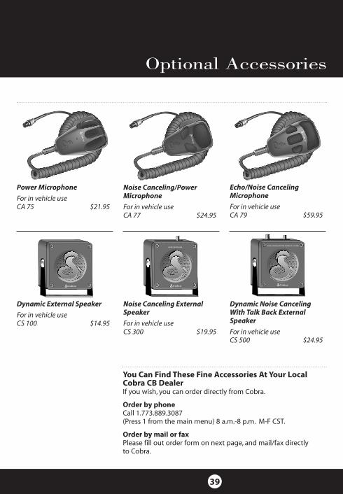
cb tranceiver

1. Power On/Off,Volume Control
2. Squelch Control
3. Dynamike
4. RF Gain
5. Delta-Tune
6. SWR CAL
7. Channel Selector
8. LED Channel Display
9. ANT Indicator
10. RX (Receive)/ TX (Transmit)LED Indicator
11. Channel 9/ Normal Switch
12. Dimmer Switch
13. CB/PA Switch
14. NB/ANL ANL Off Switch
15. S/RF SWR CAL Switch
16. Signal Strength Meter
17. Microphone
Back Side
18. Public Address Speaker Jack
19. External Speaker Jack
20. Antenna Connector
21. Power Jack
ANTPA.SP. EXT.SP. + POWER–
DATE OF MFG :JUNE 98 FCC ID:BBO3K229LTD
COBRAMADE IN CHINA
SERIAL NO.:806135776PRECISION ENGINEERED PRODUCT OF COBRA ELECTRONICS CORP. CHICAGO, ILL.60707
Controls and Indicators
A2
1 2 3 4
SIG 1 3 5 7 9 +30dB
2 3 CAL
RF
SWR
RF
DYNAMIKE RFGAIN DELTATUNESWR CAL
S /RF
S WR
C A L
NB / A NLA NL
OFF
C B
PA
BRT
DIM
CH9
NOR
RX/TX
M IN M A X M IN M A X
SQUELCH
OFF
VOLUME
5 6 7
20 21
16 8
10
18 19
1112131415
17
9

Thank you for purchasing the Cobra 29 LTDClassic CB Radio. Properly used, this Cobra prod-uct will give you many years of reliable service.
Customer SupportShould you encounter any problems with theproduct or not understand its many features,please refer to this owner’s manual. If , after referring to the manual, you still need help,call Cobra Customer Service at 773.889.3087.
Cobra Customer Service
Live operators are available M-F 8:00 am - 8:00 pm CST at:773.889.3087
Automated Technical Assistanceavailable 24 hours a day, sevendays a week. E-mail questionsto:[email protected]
Cobra on the World Wide Web:Frequently Asked Questions(FAQ) can be found on-line at:www.cobraelec.com
Our Thanks to You
A3