Embed Size (px)
Citation preview
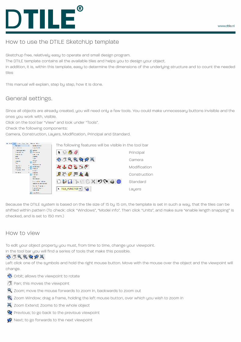
How to use the DTILE SketchUp template
Sketchup free, relatively easy to operate and small design program. The DTILE template contains al l the available ti les and helps you to design your object. In addition, it is , within this template, easy to determine the dimensions of the underlying structure and to count the needed ti les
This manual wil l explain, step by step, how it is done.
General settings.
Since al l objects are already created, you wil l need only a few tools. You could make unnecessary buttons invisible and the ones you work with, visible. Click on the tool bar “View” and look under “Tools”. Check the fol lowing components: Camera, Construction, Layers, Modification, Principal and Standard.
Because the DTILE system is based on the ti le size of 15 by 15 cm, the template is set in such a way, that the ti les can be shifted within pattern (To check: cl ick “Windows”, “Model Info”. Then click “Units”, and make sure “enable length snapping” is checked, and is set to 150 mm.)
How to view
To edit your object property you must, from time to time, change your viewpoint . In the tool bar you wil l f ind a series of tools that make this possible.
Left cl ick one of the symbols and hold the right mouse button. Move with the mouse over the object and the viewpoint wil l change.
Orbit ; al lows the viewpoint to rotate
Pan; this moves the viewpoint
Zoom; move the mouse forwards to zoom in, backwards to zoom out
Zoom Window; drag a frame, holding the left mouse button, over which you wish to zoom in
Zoom Extend; Zooms to the whole object
Previous; to go back to the previous viewpoint
Next; to go forwards to the next viewpoint
The following features wil l be visible in the tool bar
Principal
Camera
Modification
Construction
Standard
Layers

How to stack the ti les.
You do not need to start from scratch or create objects. To build your object, simply move, copy, stack, rotate and mirror the objects in the template. You can use tools from the tool bar, but it is also possible to call these functions with the keyboard, the so-called short-cuts.
To edit a ti le or ti les it needs to be selected first . Click in the tool bar or press: (space bar).Select a ti le by clicking on it . This is now caught in a blue wire frame and can be edited. To select multiple objects, hold and click to select the ti les. (Click again the object wil l de-select) To select multiple objects, hold down the left mouse but-
ton and drag a rectangle to select the ti les.
How to move
Select the ti le. Click in the tool bar or press The mouse pointer wil l turn into a cross with arrows. Click on the selected ti le and move it using the mouse. Because the grid is set to 150 mm, the ti le wil l automatically move within the pattern. Make sure the ti les are moved in a straight l ine. This is shown by the coloured (red, green or blue) dotted l ine. If the ti le is at the desired location, cl ick the left mouse button.
How to copy
Press while moving. A copy of the ti le wil l appear. With the left mouse button, the ti le can be placed in the disered position.
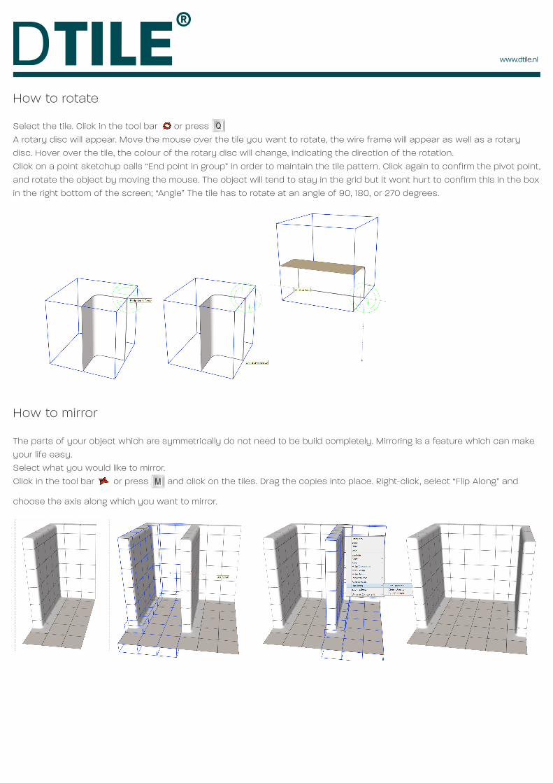
How to rotate
Select the ti le. Click in the tool bar or press A rotary disc wil l appear. Move the mouse over the ti le you want to rotate, the wire frame wil l appear as well as a rotary disc. Hover over the ti le, the colour of the rotary disc wil l change, indicating the direction of the rotation. Click on a point sketchup calls “End point in group” in order to maintain the ti le pattern. Click again to confirm the pivot point , and rotate the object by moving the mouse. The object wil l tend to stay in the grid but it wont hurt to confirm this in the box in the right bottom of the screen; “Angle” The ti le has to rotate at an angle of 90, 180, or 270 degrees.
How to mirror
The parts of your object which are symmetrically do not need to be bui ld completely. Mirroring is a feature which can make your l ife easy. Select what you would l ike to mirror.Click in the tool bar or press and click on the ti les. Drag the copies into place. Right-click, select “Fl ip Along” and
choose the axis along which you want to mirror.
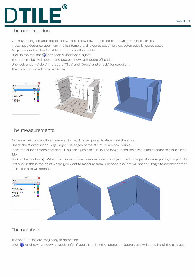
The construction.
You have designed your object, but want to know how the structure, on which to ti le, looks l ike. If you have designed your item in DTILE template, this construction is also, automatically , constructed. Simply render the ti les invisible and construction visible. Click, in the tool bar or check “Windows”, “Layers”. The “Layers” box wil l appear and you can now turn layers off and on. Uncheck under “Visible” the layers “T i les” and “Grout” and check”Construction”. The construction wil l now be visible.
The measurements.
Because the construction is already drafted, it is very easy to determine the sizes. Check the “Construction Edge” layer. The edges of the structure are now visible. Make the layer “Dimensions” default, by ticking its circle. If you no longer need the sizes, simple render this layer invis-ible. Click in the tool bar When the mouse pointer is moved over the object, it wi l l change, at corner points, in a pink dot. Left click, if this is the point where you want to measure from. A second pink dot wil l appear. Drag it to another corner point. The size wil l appear.
The numbers.
The needed ti les are very easy to determine. Click or check “Windows”, “Model Info”. If you then click the “Statistics” button, you wil l see a l ist of the ti les used.