Embed Size (px)
Citation preview

1
HOW ARE TECHNOLOGICAL CHANGES IN BOUNDARY
OBJECTS ENACTED IN DESIGN AND CONSTRUCTION NETWORKS?
John E. Taylor
Assistant Professor
The University of Texas at Austin
1 University Station C1752
Austin, TX 78712-0273
ABSTRACT
Interorganizational networks are proliferating as a form of industrial organization. However, the
processes by which networks of firms implement boundary-spanning technological changes
remain poorly understood. In this paper I explore the implementation of three-dimensional
computer-aided modeling tools in 26 design and construction organizations. I analyze empirical
data collected over a seven month period to induce a set of antecedent constructs that enable the
evolution from 'printed sets of plans' to 'virtual model' boundary objects. The findings highlight
the importance of addressing regulative, technological, work, and organizational issues at the
interfaces between firms in networks when implementing boundary-spanning technological
change.

2
INTRODUCTION
The ability for organizations to sustain competitive advantage rests in part on the successful
implementation of new technologies. Over the past several decades information systems have
provided a steady stream of technological changes for organizations to employ to keep apace
with competitors. Many of these changes have taken the form of integrated information systems
that some researchers contend require a fundamental reexamination of the concepts of markets
and hierarchies (Malone, Yates, & Benjamin, 1987). Within hierarchically organized firms,
enterprise-wide integrated information system implementation has proven to be wrought with
unforeseen hazards (Block, 1983; Davenport, 1998; Sumner, 2000). Block (1983) identified a
dozen categories of determinants to explain enterprise-wide information system implementation
failure. Despite the potential for failure, the successful implementation of integrated information
systems provides a rich source for sustained competitive advantage in firms (Mata, Fuerst, &
Barney, 1995; Powell & Dent-Micallef, 1997).
In parallel with the development of integrated information systems, interorganizational
networks have increasingly replaced traditional vertically-integrated hierarchies over the past
several decades (Barley, Freeman, & Hybels, 1992; Pekar & Allio, 1994). Interorganizational
networks were first discovered in the Massachusetts house building industry by Eccles (1981).
Eccles described these networks as quasifirms where house building contractors maintain long-
term contractual relationships with subcontractors even if those subcontractors did not provide
the lowest market price to perform their work. He described the quasifirm form of organization
as existing between the traditional markets and hierarchies outlined in transaction cost economics
by Williamson (1975). Williamson (1985) later supplemented his transaction cost framework

3
with the concept of hybrid organizations as an intermediate form of organization existing
between markets and hierarchies.
Since these early studies of interorganizational networks, research has extended beyond
economic exchange arguments to consider networks as a new, independent form of organization
(Miles & Snow, 1986; Powell, 1987, 1990). Researchers of the network form of organization
seek to understand how interactions between organizations are governed (Granovetter, 1992;
Jones, Hesterly, & Borgatti, 1997; Stinchcombe, 1985), how firms select network partners
(Beckman, Haunschild, & Phillips, 2004; Galaskiewicz, 1985; Pekar & Allio, 1994), the stability
of interactions between networked firms (Gulati, 1995; Powell, White, Koput, & Owen-Smith,
2005), and how knowledge flows across networked firms (Appleyard, 1996; Uzzi & Gillespie,
2002). Although research on interorganizational networks investigates the relational aspects of
networks and the knowledge exchanged, interorganizational researchers have largely ignored the
interstitial objects that connect the work and provide a vehicle for exchanges of knowledge
between disparate organizations in networks.
The rise in research on and usage of interorganizational networks led information systems
researchers to investigate the implementation of these systems across organizational boundaries
in networks. Numerous researchers found the implementation of interorganizational information
systems to be a source of competitive advantage in interorganizational networks (Bakos, 1997;
Bakos & Treacy, 1986; Cash & Konsyniski, 1985; Johnston & Vitale, 1988). Cash and
Konsynski (1985) proposed that information systems can enable the redrawing of organizational
boundaries. Some researchers proposed that interorganizational information systems themselves
provide the integrating mechanisms to connect organizations into networks (Argyres, 1999;
Johnston & Lawrence, 1988; Venkatrama & Zaheer, 1990).

4
The linkage between integrated technologies and interorganizational information systems
led to a thread of research pursuing the notion that competitive advantage lay in reducing the
boundaries of organizations, even to the point of organizations becoming boundaryless (Devanna
& Tichy, 1990). However, more recent research finds that boundary activities may actually
increase in significance in boundaryless organizations (Cross, Aimin, & Louis, 2000; Hirschhorn
& Gilmore, 1992). Though the formal, hierarchical boundaries may appear to be reducing in
importance, integrated information systems can become increasingly important intermediate
boundary objects to link the work and enable the exchange of knowledge between disparate
organizations in networks (Briers & Chua, 2001; Pawlowski & Robey, 2004).
Star and Griesmer (1989) introduced the concept of boundary objects to describe objects
that inhabit intersecting social worlds while at the same time satisfying the information
requirements for each separate group. Interorganizational information systems are one example
of a boundary object that connects the work of different occupational fields (Levina & Vaast,
2005; Pawlowski & Robey, 2004). Other examples of boundary objects include prototypes
(Carlile, 2002), sketches (Henderson, 1991, 1999), or designs (Bechky, 2003). These boundary
objects play a mediating role to connect the disparate social worlds of the designers and the
builders of those designs while at the same time enabling individuals from both groups to
conduct their work.
In Henderson's (1999) ethnographic study of the evolution from paper-based to computer-
aided drafting among designers we learn that technological change in boundary objects can have
a significant impact in the structuring of work and status of individuals within design firms. This
study of implementing technological change in boundary objects provides a rich understanding
of the difficulties a single firm faces. However, it offers little direction to navigate technological

5
changes in boundary objects that span organizational boundaries. If technological change in
boundary objects can erode current patterns of work within a firm, what impact can it have on
interdependent firms in interorganizational networks? Though researchers have explored the
issues associated with interorganizational information system boundary objects in networks
(Briers & Chua, 2001; Pawlowski & Robey, 2004), there is little in the way of guidance on how
a network of firms would go about implementing technological changes of this kind. If the
successful implementation of interorganizational systems is critical to sustaining competitive
advantage (Bakos, 1997; Bakos & Treacy, 1986; Cash & Konsynski, 1985; Johnston & Vitale,
1988), then firms involved in interorganizational networks must understand how to implement
technological change in boundary objects to remain competitive.
This paper explores the question of how firms in interorganizational networks implement
technological change in boundary objects. Extending from previous work on the evolution from
paper-based to computer-aided drafting in design firms (Argyres, 1999; Henderson, 1991, 1999;
Manske & Wolf, 1989; Robertson & Allen, 1992; Salzman, 1989), I explore the recent evolution
from two-dimensional (2D) computer-aided drafting (CAD) to 3D CAD in design and
construction networks. The boundary object exchanged between designers and contractors
remained stable in the evolution from paper-based drafting to 2D CAD. Designers continued to
share designs with the contractor as a set of paper-based line drawings. However, with the
evolution from 2D CAD to 3D CAD, the disparate social worlds of design and construction are
brought together to co-create a virtual model of the planned structure.

6
RESEARCH SETTING AND METHODOLOGY
I employed a qualitative approach (Eisenhardt, 1989; Glaser & Strauss, 1967; Strauss & Corbin,
1990; Yin, 1989) to gather and analyze the experiences and perspectives of designers and
contractors on their successful implementation of 3D CAD tools. I asked informants to describe
two recent projects; one prior to the implementation of the tool, and a similar project after the
tool had been implemented where the usage of the tool successful. I then asked the informants to
elaborate on the aspects of the implementation that made it successful. I also spent several
weeks observing the implementation of 3D CAD within and across design and construction
organizations. From this data I developed a grounded understanding of how firms in
interorganizational networks successfully implement 3D CAD software and was able to induce a
set of antecedent constructs relating to successful boundary object technological change in
design and construction networks. Because this boundary object change occurred at the
boundary between the intersecting social worlds of construction and design, I analyzed the
variances in perspectives in order to explore how implementation issues varied across
interorganizational network boundaries.
Sample and Data Collection
Researchers suggest that qualitative case research include employ multiple data collection
methods in order to increase the validity of the constructs identified (Eisenhardt, 1989). In this
study, I employ multiple data collection methods; including, ethnographic interviews, direct
observation, and review of primary documentation. Researchers recommend using multiple case
studies to further increase internal construct validity (Eisenhardt, 1991). To accomplish this, I
replicated the data collection effort across 26 different organizations in this research

7
investigation. During the course of this research I spent several weeks as an observer of six 3D
CAD projects involving both design and construction organizations.
By triangulating the findings across these different cases and data collection methods I
strengthen the validity of the findings (Eisenhardt, 1989). The data collection effort took place
over a seven month period from June 2004 through December 2004. Of the firms investigated in
this project, 13 were construction firms and 13 were design firms. In order to select firms for
inclusion in this study, I specifically approached companies that had successfully implemented a
3D CAD tool. Therefore, the organizations in the study were selected for their ability to provide
analytic generalization, they were not randomly sampled (Yin, 1989).
Research Context
From 2D CAD to 3D CAD. Argyres (1999) found that the implementation of 3D CAD
among the firms that designed and developed the B-2 "Stealth" bomber both enhanced
coordination and enabled the creation of an entirely new kind aircraft. He postulated that 3D
CAD could be a source for competitive advantage in strategic alliances when compared to earlier
advances in CAD. According to one 3D CAD tool provider, this technology will have similar
coordination benefits in the design and construction industry. He describes the development of a
virtual model of a building with 3D CAD as follows:
"...a computer model database of building design information, which may also contain information about the building's construction, management, operations, and maintenance. From this central database, different views of the information can be generated automatically, views which correspond to traditional building design documents, like plans, sections, elevations, quantity take-offs, door and window schedules, 3D model views, renderings and animations. Because these resulting documents can be derived from the same database, they are all coordinated and accurate." (Barron, 2003: 2 emphasis added)

8
Harty (2005) documented how the adoption of 3D CAD on a large design and construction
project led to coordination difficulties between firms. Where this technology creates an
opportunity to improve the coordination and accuracy of the design and construction model
(Barron, 2003), it can also create coordination difficulties across firms in design and construction
networks. Mitropoulos and Tatum (1999) found that the adoption of 3D CAD can be hindered
by decision processes within construction organizations. Whyte and her colleagues (1999)
determined that 3D CAD software is being adopted more slowly than its predecessor 2D CAD.
Harty's (2005) study of the adoption of 3D CAD is instructive in that it suggests that social and
organizational contexts need to be taken into consideration to understand the adoption of this
technology. He pointed out how the technology had spillover effects beyond the adopting firm
(Harty, 2005). However, the process by which design and construction firms in
interorganizational networks address these spillover effects and successfully implement
boundary object technological change remains poorly understood.
3D CAD is unique when compared to the earlier evolution to 2D CAD technology because
it involves designers and contractors working together to co-create a virtual representation of a
building. Numerous studies point to the significant changes it introduced within organizations.
Manske and Wolf (1989) identified the emergence of new roles to complement new skill
requirements within design organizations that implemented 2D CAD. Salzman (1989) also
identified how the skill requirements of employees in design firms changed as a result of
implementing 2D CAD. Robertson and Allen (1992) and Henderson (1999) each describe how
work was restructured within organizations evolving from drafting to 2D CAD. Henderson
(1999) further described in her ethnographic account of the implementation of 2D CAD how the

9
relations between employees changed. None of these studies, however, identified changes
occurring across organizational boundaries.
With both paper-based drafting and 2D CAD, building information was typically
exchanged between firms in the form of a printed set of plans. The plans themselves then
became the visual representations upon which discussions within and between design and
construction organizations were based. This boundary object (the printed set of plans) between
designers and contractors is central for coordination and provides the locus for elaborating and
resolving conflicts. The plans span the separate social worlds of designers and contractors and
satisfy the information requirements of each, meeting Star and Griesmer's (1989) definition for a
boundary object.
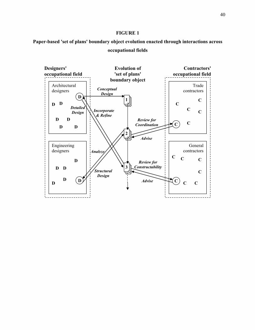
Figure 1 illustrates some of the interactions the occupational fields of design and
construction have with the 'printed set of plans' boundary object. Architectural designers create
conceptual designs either through sketching or the development of computer-aided designs in 2D
CAD. This printed set of conceptual design plans becomes the initial boundary object which is
shared with engineering designers to analyze and create structural designs which are then
reviewed for coordination by trade contractors. The architectural designer incorporates the
structural design, refines the original conceptual design, and creates a detailed design which is
shared with the general contractor as a printed set of plans. The general contractor reviews this
printed set of plans for constructability and provides requests for information to advise the
architectural designer of any suggested or required changes. This process of interaction with the
printed set of plans goes on throughout the design and construction process until ultimately the
general contractors and trade contractors edit (or "redline") the set of plans to reflect what was
actually constructed.

10
-------------------------------------- Insert Figure 1 about here
--------------------------------------
Figure 2 illustrates how design and construction occupational fields interact with the 'virtual
model' boundary object. With 3D CAD, organizations from the separate social worlds of design
and construction are brought together to co-create a 'virtual model' for a building. Design and
construction organizations have some flexibility in the extent to which they co-create virtual
models. They can focus the creation of the virtual model internal to their own organization, they
can co-create the model with other designers or contractors on a building project, or they can
move beyond sharing with project partners and co-create the model with material suppliers. In
Figure 2, however, we describe the process by which designers and contractors co-create a
virtual model boundary object.
-------------------------------------- Insert Figure 2 about here
--------------------------------------
Where the evolution of a 'printed set of plans' was separated in time, the co-creation of a 'virtual
model' requires overlapping of the work. Some designers described this as "bringing the
contractor on board early." It is in these interactive sessions represented in Figure 2 where
designers design, analyze, incorporate and refine while contractors review, advise and
coordinate. The fact that designers and contractors come from different social worlds with
different interpretations of 'printed sets of plans' becomes evident in these sessions. Designers
described surprises in this co-creation environment as "we aren't normally thinking about how
wall lines interact with the ceiling" while "the guy with building experiences is thinking 'what
kind of wall is that?'." This tighter interaction created some problems initially in the co-creation

11
of the virtual model. One contractor described that "there are deep seated issues with getting
people from different disciplines to talk to each other and get along."
3D CAD uses virtual objects to represent various elements of a building. When a set of
printed plans were shared between organizations, each disparate organization could define the
elements as they wished. When a designer or a contractor viewed a set of printed plans
illustrating a glass exterior of a building, the contractor might describe it as a curtain wall while
an architect might describe it as a facade. However, when individuals from the separate worlds
of design and construction are brought together to co-create this same glass exterior, differences
in naming conventions can lead to coordination difficulties and conflicts.
Design and Construction Organizations. I investigate the implementation of 3D CAD
software in 26 design and construction organizations. Design and construction networks have
been the focus of a number of recent innovation studies pointing out issues associated with
interdependent, networked nature of this industry and its work (Gann & Salter, 2000; Miozzo &
Dewick, 2002; Salter & Gann, 2003; Taylor & Levitt, 2004). Each of these studies identified
learning in the project-based design and construction networks as an inhibitor to change. None
of these studies, however, investigated technological change in the boundary objects that connect
the disparate worlds of design and construction. In this paper I investigate the technological
change from the 'printed set of plans' boundary object that connect design and construction
organizations to the co-creation of a 'virtual model' in order to better understand how change
occurs in these networks.
The design and construction firms included in this study were not selected based on the
implementation of a specific 3D CAD tool. I was less interested in the specific tool and more
interested in identifying trends across different types of tools that led to successful

12
implementation. I included only firms that had completed at least one project using 3D CAD
software. Of the firms included in the study, 13 had completed between one and five 3D CAD
projects, 9 had completed between six and twenty-five projects, and 4 had completed more than
twenty-six projects.
Table 1 below provides details about the 26 firms included in the study. In addition to data
about the specialization of each firm (designer or contractor), I tracked the location of the
company headquarters (US, Europe or Asia) and the scale of that firm's operations (local,
national or international). Regarding each firm's technology implementation, I tracked the
number of 3D CAD projects they had completed (1-5, 6-25, or more than 26 projects).
I also tracked the degree to which the 3D CAD work was co-created with other firms.
Four of the firms in the sample were using 3D CAD successfully in their firm without co-
creating the 'virtual model' with other firms. Twelve of the firms in the sample co-created the 3D
CAD model with another specialist firm on the project (e.g., designers working together with
contractors). Ten of the firms in the sample were actually moving beyond co-creating the model
between design and construction firms. These firms extended their cooperation in the
development of the 'virtual model' of the building with material suppliers (e.g., structural steel
fabricators and window manufacturers) who would fabricate elements of the building directly
from the model. It was not my original intention or expectation to observe co-creation of 'virtual
model' artifacts at this level. However, it instructive to understand the further reaches of the
propagation of boundary object technological change.
-------------------------------------- Insert Table 1 about here
--------------------------------------

13
Interview data was collected in interviews of approximately three hours in duration. I collected
approximately 90 hours of interview data during the course of the data collection. An interview
protocol was used during the interviews to make sure the interview covered the basic discussion
points. However, the protocol was designed in such a way to encourage the interviewees to
speak at length, in their own words, about their experiences before and during the successful
implementation of 3D CAD in the context of specific projects.
In addition to interview discussions, direct observations of six 3D CAD projects involving
designers and contractors were made over a period of several weeks. I was invited to attend
project and company meetings, to visit project sites, to generally observe the interaction between
participants on the projects, and to discuss my observations with my informants within the
design and construction organizations involved. I took extensive notes during this process and
took digital photographs for use in my data analysis. Interview discussions and noted
observations were recorded in a numbered set of field research notebooks. Interview discussions
were also recorded using a digital voice recorder.
Whenever possible, I requested hard copies of materials discussed during interview
discussions and observations. Data collected included contract documents, process flow
diagrams, project schedules, design models, bills of materials, project decision schedules,
animations of design models, and any other information that might lend insight into the
successful internal and interorganizational implementation of 3D CAD. This primary
documentation was attached to my field notebooks and often elucidated concepts that were not
entirely clear when reviewing the notes from an interview or observation. Overall, I was able to
manage the reliability of the findings by keeping an indexed, organized database of my field
notebooks, audio interview files, photographs, and documents collected.

14
Content Analysis
Because I did not use a structured interview, interviewees were able to spontaneously discuss
topics that they felt were important regarding their implementation of 3D CAD software.
Interview quotes were only included in the qualitative content analysis if they specifically dealt
with the implementation of 3D CAD software. Quotations varied from short quotes to longer,
several sentence discussions. The idea was to encapsulate a complete thought that could be
compared and contrasted with other quotations to formulate constructs.
I performed a line-by-line microanalysis of the data I collected (Strauss & Corbin, 1990).
From the microanalysis process, 282 anecdotal quotes relating to successful 3D CAD
implementation emerged from the raw data. All quotations identified in the data that were
relevant to implementing 3D CAD were coded into a database. The quotes were roughly equally
distributed between designers (n=158 quotations) and contractors (n=124 quotations). These
quotes were then analyzed using the constant comparative method (Glaser & Strauss, 1967) to
develop and refine a set of 27 conceptual categories. I then systematically analyzed the 282
relevant implementation anecdotes to identify patterns in an axial coding process (Strauss &
Corbin, 1990).
IMPLEMENTING BOUNDARY OBJECT TECHNOLOGICAL CHANGE
The content analysis revealed 27 unique conceptual categories that relate to successful 3D CAD
software implementation in design and construction networks. Of these antecedents, 14 account
for over 85% of the coded occurrences analyzed in the study. In order to emphasize parsimony I
will only include the antecedent constructs that represent 85% of the collected data in the

15
following discussion. Researchers suggest that focusing on constructs that represent 80% to 90%
of the data to identify key variables (Dunteman, 1989). In Table 2 below, I list the 14 key
antecedent constructs of successful boundary object technology implementation. For each
determinant I include the frequency of quotations for designers, for contractors, and for all firms
in the study.
-------------------------------------- Insert Table 2 about here
--------------------------------------
Upon closer examination of the determinants presented in Table 2, I observe that there is both
strong agreement and variance in the frequency of responses for each key antecedent when
comparing the implementation perspectives across occupational fields. This is not surprising
given the separate social worlds from which designers and contractors originate. By comparing
relative frequencies across the design and construction functions we can discern more distinctly
the separation of the antecedents across design and construction implementation perspectives.
The difference between the relative frequencies for designers and contractors for each key
antecedent are tabulated in Table 3. For each antecedent the number of standard deviations from
the mean of the variances in the frequencies is listed.
-------------------------------------- Insert Table 3 about here
--------------------------------------
Designer's perspective of 3D CAD implementation
It is more important for designers than contractors to address issues of liability and to address
contractual constraints (1 to 2 standard deviations from mean variance). When the printed plans
were the boundary object connecting designers and contractors, the plans contained a notation

16
that indicated they were not to scale. With the co-creation of a virtual model boundary object, it
is no longer feasible to create designs that are not to scale. Contractors must be able to plan
production and fabrication from the virtual model and, as such, dimensions and the connections
between objects in the building information model must be precise. This introduces new liability
considerations for design organizations. With printed plans that are not to scale, contractors
make adjustments to accommodate precise connections between building objects. With a virtual
model, however, if a dimension is imprecise and an element does not connect to a building
properly during construction, then a contractor can claim that this is the fault of the designer.
Designers explained that:
"in design professional's drawings, the dimensions are not exact, a contractor interprets these and creates shop drawings with exact dimensions … if a dimension is wrong it's the contractor's fault, if derived from the 3D CAD model the architect would be responsible"
This comment was echoed by a contractor who described why, in some instances, they
recreate the 3D CAD model even when it is furnished by the architect. He described this
concern over liability as follows, "if we get a BIM model from an architect there may be
mistakes since the architect doesn't guarantee that the model is correct." Surprisingly, issues of
liability had not been addressed explicitly in contracts. Designers described 3D CAD technology
as being sufficiently new that it had not been contemplated by the legal profession. Firms that
successfully implemented 3D CAD within their design and construction network made only
minor modifications to the contract documents. Interestingly, in some cases the virtual model
co-created by the designers and the contractors became a component of the contract. One
designer describes the virtual model becoming part of the contract documents as follows:
"in our last project the 3D CAD model became part of the contract documents … the legal side of this is not too complex but there is a fundamental distrust of digital data, you have to tell the structural steel fabricator that the data is accurate"

17
More generally, designers spoke of contract changes required to successfully implement
3D CAD in their network as needing to "add a paragraph or two on a case-by-case basis" or "we
only added a front page to the contract." Although the virtual model is co-created across
designers and contractors, it takes its initial form in design organizations. One of the stated
benefits of 3D CAD over 2D CAD is more accuracy (Barron, 2003). However, achieving that
accuracy requires design firms to address contractual constraints and address issues of liability.
Contractor's perspective of 3D CAD implementation
In contrast to designers, successful implementation of 3D CAD in contractor organizations
focused on working with designers to cross-pollinate ideas across firms (2 to 3 standard
deviations from mean of variance). The idea that design and construction firms would cross-
pollinate ideas with 3D CAD would seem to indicate that this level of interaction did not exist in
the past. Unlike the exchange of a set of printed plans with paper-based drafting and 2D CAD,
the co-creation of a virtual model requires disparate design and construction organizations to
work together more closely. In doing so, construction firms are able to more clearly articulate
their knowledge of constructability issues and get changes into the model that otherwise would
have had to be worked out in the field during construction or later "with a hammer."
According to contractors, the co-creation of a virtual model enabled firms to "swap roles to
understand what is important to other specialists" and "by putting teams together with the model
we're able to get unintended benefits." One firm described that they were able to gain an extra
floor in the building due to cross-pollination of constructability ideas in design:
"normally this building would be 15 foot floor-to-floor height, we gained a floor in the building by achieving a 14 foot floor-to-floor height"

18
Contractors also expressed the need to experiment with technology more frequently than
designers (1 to 2 standard deviations from mean of variance) when implementing 3D CAD.
Contractors have been described by researchers as having difficulties adopting new technologies,
in particular 3D CAD (Mitropoulos & Tatum, 1999; Whyte, Bouchlaghem, Thorpe, & McCaffer,
1999). In contrast, designers have been described as being creative and engaged in
experimenting with new ideas (Henderson, 1999; Salter & Gann, 2003). In order to successfully
implement 3D CAD, contractors need to develop a more experimental attitude. One contractor
described that "one big hurdle for 3D CAD is inertia we've always done it this way, we're a
conservative industry." Another contractor described an initial passive resistance to 3D CAD as
"a lot of saying 'yes' but nodding 'no'... not in my back yard." Some contractors described a
process of as long as six months of experimentation with 3D CAD, hiring and replacing
numerous CAD managers, and conducting a number of team-building exercises before achieving
successful implementation.
A practical concern for contractors vis-à-vis designers in implementing 3D CAD was the
need to work with firms using the same software (1 to 2 standard deviations from mean
variance). When a designer implements 3D CAD, their firm can build a virtual model with their
own internal resources or co-create the virtual model with the contractor. However, for a
contractor to implement 3D CAD successfully it requires the initial building information model
input from the designer. Otherwise, the contractor has to recreate the entire design. In the words
of one contractor "even if I can use 3D CAD, if the designer can't use it why bother." Another
contractor describes their experience on a recent project where their partners did not use 3D
CAD as follows:
"on our last project all our partners were still using 2D CAD so we had to constantly go from 3D to 2D to communicate files rather than slicing and dicing into layers"

19
In contrast with designers, in order for contractors to successfully implement 3D CAD they
must take advantage of opportunities to cross-pollinate ideas across firms about constructability,
they must deal with inertia against change in their occupational field to experiment with
technology, and finally they must identify and work with firms using the same 3D CAD software.
Construction firms that address these three areas are able to successfully implement
technological change in the boundary object that connects their work to design organizations. In
doing so, construction firms identified tremendous increases in productivity. One firm described
how on their first implementation of 3D CAD they were able to reduce the number of revisions
from a running average of 30-35% to 10%. And the accuracy continued to improve with the
move from using a set of printed plans developed by a designer to co-creating a virtual model
with the designer.
Shared perspectives on 3D CAD implementation
In addition to the specific perspectives of designers and contractors, there were a set of shared
perspectives common across both occupational fields. The antecedent constructs of similar
importance (from 0 to 1 standard deviations from mean variance in Table 3) to designers and
contractors can be classified into four areas; at the organization interface, at the technology
interface, at the work interface, and internal change management. I will discuss the findings in
each of these areas in the following sections.
Organization interface. Designers and contractors both reported that addressing interfaces
between their respective organizations was critical to successfully implementing 3D CAD tools.
This area contains the largest relative frequency of responses. At the organizational interface
between designers and contractors, networks that increase collaboration between firms are more
20
effective at implementing 3D CAD across organizations. One contractor describes this
collaboration as a way to both eliminate conflicts and to identify opportunities for improving the
design. The contractor described how with improved collaboration the designer "gets input from
different people" and in doing so "immediately sees interferences especially across disciplines
like a pipe going through a beam." A contractor also described how improved collaboration with
the designer actually created opportunities to increase the density of a building. The contractor
indicated that "in a few cases (the designer) identified spaces where we can route ducts that
would normally be for another system.” Attaining the benefits of cross-pollinating ideas across
firms described earlier is contingent upon increasing collaboration between firms in the design
and construction network.
Some firms in the sample who successfully implemented 3D CAD tools progressed beyond
collaboration to develop partnerships between firms in the network. An architect described how
“when you have ongoing relationships you can leverage learning to work together with (3D
CAD) over and over again." The architect described this learning that comes through
partnerships as “a function of percolation.” A contractor also described the use of partnerships in
successful 3D software implementation across designers and contractors in terms of learning.
The contractor described that “establishing more partnerships and not working with different
firms from project to project is important as it takes time to learn to work together with a new
technology and develop a common strategy.” Design and construction firms that address
interactions through collaboration and partnership are able to strengthen interorganizational
learning associated with the new technology.
A smaller group of firms in the study advanced beyond collaboration and partnership and
explored how 3D CAD could be implemented to improve processes beyond their own firm. In

21
doing so, these firms understood shared interests among firms in their network. With the limited
meaningful interaction available using a printed set of plans, design and construction firms had
difficulty understanding each others' interests. If a designer does not consider a contractor's
interests and vice-versa, the implementation of 3D CAD or other technologies in the design or
construction organization can be counterproductive to the other due to interdependencies in the
work. One contractor interviewed described how a sharing of interests is a step beyond
partnership. They described that:
“twice per year we have a meeting to discuss how we can make our partnerships deeper and more profitable for both partners … partnership is not just an empty phrase, we want each other to succeed.”
An architect in the study made a similar claim, in this case stressing how improving the
interactions between designers and contractors is more important than issues related to
technology implementation. The architect pointed out that:
"developing cooperative relationships is more important than the technology … participants need to sit around the same table and realize their shared interests.”
Although there were different degrees to which firms in the sample addressed
organizational interfaces between designers and contractors, firms that successfully implemented
3D CAD improved collaboration, developed partnerships, or moved beyond partnership to
understanding each other's shared interests. This highlights the fact that 3D CAD software
impacts both designers and contractors, even if they adopt the technology separately.
Technology interface. In addition to addressing organizational interfaces, both design and
construction firms must address the interoperability of technology at the technological interface
between their firms. In other words, in order to co-create a virtual model, the 3D CAD software
in both firms must be capable of opening and editing the electronic building information model.

22
One contractor described a recent project where all the participating firms were using 3D CAD
but that "there were interoperability problems (due to) 20 different file formats." Generally,
firms addressed the technology interface between organizations by requiring their partners to use
the same 3D CAD software of the same version. One designer describes how they successfully
implement 3D CAD across their design and construction network as follows:
"all our (partners) have to be on IFC compliant software of the same version … it's in the contract" [Note: 'IFC' refers to Industry Foundation Classes, a content standard for 3D CAD objects in the building industry]
Achieving the potential of 3D CAD requires firms to share and co-produce electronic files
of buildings. To do so, interfaces between firms and technologies need to be addressed to
accommodate the development and learning of interorganizational routines. The deeper the
relationship that bridges the interactions between designers and contractors, the more likely firms
are to develop novel solutions to design and construction problems that benefit both partner
firms.
Work interface. I spoke of the development and learning of interorganizational routines
and how addressing the interfaces between organizations and technologies in networks can help
to address these. In this section I will describe more specifically how the scope and pattern of
work across firms changed for design and construction firms that successfully implemented 3D
CAD software. As one architect described, "the big change with (3D CAD) is not technological,
it's changing the process.” Design and construction firms that successfully implemented 3D
CAD redistributed work among firms, developed standards for interaction, and developed a
system understanding of the project.
The key antecedent of redistributing work among firms in design and construction
networks was the most cited construct in the study (responses relating to this construct alone

23
account for 13.5% of all responses). Both designers and contractors described how the use of 3D
CAD software shifted some of the work traditionally done by contractors and material suppliers
into the domain of the designer. With the development of a virtual model, designers must
provide more detailed and more accurate models. Contractors must also change their work
practices to successfully accommodate 3D CAD into their work. One contractor described how
“in order for (3D CAD) to work, the flow of work had to change … we're relying more and more
on 3D stations in the field.” The pattern of work is changing as a result of technological change
in the boundary object connecting the work of designers and contractors. Work that used to be
completed separately in company offices is now being shifted into the field where designers and
contractors can co-create virtual models together more effectively.
A contractor describes the shift in work from a supplier to a designer stating that:
“the specification process for one complex building material took 100 to 150 parameters and 100 phone calls to define, we resolved this by moving the knowledge to the step where the architect specifies that product.”
In response to the changing scope and pattern of work introduced by 3D CAD, a designer
that successfully implemented the boundary object technological change described that they:
“bring sub trades forward so that the steel (contractor) works with the engineer and the window manufacturer works with the architect… it yields better technical detailing”
In the move from 2D CAD to 3D CAD, work is being redistributed among firms in the
network. However these redistributions are not enacted without difficulty. With 3D CAD, some
work is redistributed from contractors to designers. However, for the network to accrue the
benefits of this additional work, the virtual model must be used by firms downstream in the
process. One example of a designer's and a contractor’s breakdown in process was described as
follows:

24
"if everyone doesn’t follow the process it all falls apart … if the (contractor) ignores the upstream designers' (3D CAD model) in one fell swoop the process is stopped and the benefits disappear"
Examples such as this illustrate the mutual adjustment required by firms in the network in
order for implementation of 3D CAD to be a success at the level of the network. If one of the
partners fails to adjust and utilize the extra work performed by the designer then 3D CAD
implementation fails. Design and construction firms that were able to manage the mutual
adjustment process and successfully implement 3D CAD developed tighter collaborations and
partnerships. Improving the relationships at the organizational interface in the network enabled
design and construction firms the flexibility to redistribute work.
Another key antecedent that relates to the changing patterns of work required by 3D CAD
software is the development of standards for interaction between firms. After work has been
redistributed and firms mutually adjust, design and construction firms must begin accessing and
developing a single virtual building information model. One designer described how they
addressed the development of interaction standards as follows:
“we set up coordination between disciplines so that the architect never touches the structural pieces, the structural engineer never touches the architectural pieces and if there is a change, there must be a web meeting … we require on all projects a basic set of rules be followed.”
Alongside the redistribution of work and developing standards for interaction, both design
and construction firms expressed the need to develop a system understanding of the design and
construction process. In other words, just as shared interests enabled design and construction
firms to understand and consider each others' needs, the change in scope and pattern of work
required design and construction firms to understand each others' work. Design firms described

25
hiring designers with actual construction experience who understood "how things go together."
Construction firms reported similar changes in hiring employees with more design experience.
Internal change management. All of the changes discussed thus far relate in some way to
how design and construction organizations, work patterns, and technologies interact with each
other. Since the technological change was in a boundary object that connects designers and
contractors this is to be expected. However, firms also reported addressing issues of change
management within their organizations. In design and construction organizations, firms were
only able to successfully implement 3D CAD after they were able to obtain sufficient training.
Another key antecedent for explaining successful 3D CAD implementation was when firms
worked with an external change agent. Firms described a "Boeing effect" where larger design
and construction firms would require the smaller partners in their network to implement 3D
CAD. Other firms described certain projects being of significant importance driving firms to
implement 3D CAD. In the case of design and construction firms based in Europe, several
described working with national agencies that cover the initial costs of learning 3D CAD.
DISCUSSION
This research demonstrates how technological change in boundary objects in interorganizational
networks can require considerable mutual adjustment in the interfaces between interdependent
organizations. Previous research has shown how changes to boundary objects within
organizations have restructured work (Henderson, 1991, 1999; Robertson & Allen, 1992),
changed relationships between employees (Henderson, 1999), and changed the skill requirements
for the various roles (Manske & Wolf, 1989; Salzman, 1989) in design firms. Other research on
the successful implementation of 3D CAD as an interorganizational information system in the

26
defense aviation industry found agreement on a technology platform and object naming
conventions was central to implementation success (Argyres, 1999). I observe each of these
phenomena occurring in boundary object technological change across organizations in an
interorganizational network.
Each of the investigations into the implementation of 2D CAD to replace paper-based
drafting discovered that boundary object change restructures work and, in doing so, changes the
skill requirements for employees in design firms (Henderson 1991, 1999; Manske & Wolf, 1989;
Robertson & Allen, 1992; Salzman, 1989). I identified this in the interdependent work interface
that connects designers and contractors. The introduction of 3D CAD across design and
construction organizations required work to be restructured, requiring design and construction
firms to redistribute work among firms. This change also shifted skill requirements across
design and construction firms. Firms described needing to develop a system understanding of
each others' work. This caused both design and construction firms to change their hiring
practices and also led to the emergence of new roles within both firms.
In addition to the redistribution of work among firms and the development of a system
understanding of work, in interorganizational boundary object change I identified the need to
develop standards for interaction. Though, not a study of boundary object change, Argyres’
(1999) investigation of the implementation of 3D CAD in the defense aviation industry also
identified the standardization of work practices as a key component to 3D CAD implementation
success. He described a 'deep standardization' which enabled teams from different organizations
to work together more seamlessly, decreasing the amount of coordination required to do the
work. Within a firm, employees who work together on a continual basis can work together more

27
seamlessly to adjust to changes in work. However, in a network of firms, collaboration on one
project does not necessarily mean there will be collaboration on other projects.
In the development of the B-2 bomber (Argyres, 1999), the firms in the project network
will not necessarily work together on the next aircraft development project. In the design and
construction industry projects are smaller in scope and shorter in duration than an aircraft
development project. The composition of design and construction firms in a network can be
stable, but fluctuations in participation and lapses in time between projects make learning how to
work together with the new boundary object a slow process. Developing standards for
interaction is an important antecedent to address in interorganizational network boundary object
change.
Henderson (1999) described how relationships between employees in design organizations
changed as a result of the implementation of 2D CAD. My investigation of interorganizational
boundary object change also revealed a significant organizational interface component. Change
in the boundary object created changes in the work across design and construction firms. To
address the changing scope and patterns of work firms in interorganizational networks increased
collaboration, developed partnerships, understood each others' shared interests, and ultimately
were able to cross-pollinate ideas across firms. In Henderson's (1999) investigation the
evolution from sketches to 2D CAD disrupted relationships and the CAD implementation was
described as a failure. I focused my data collection on design and construction firms that had
successfully implemented 3D CAD. These firms addressed relational disruptions caused by
change in the boundary object by strengthening the relationship between organizations when
implementing 3D CAD. Argyres (1999) also identified the importance of a trusting relationship
between organizations implementing 3D CAD.

28
In addition to the organization and work interface concepts identified by previous
researchers of boundary object change within firms, I identified regulative interface and
technology interface issues in networks. Firms in design and construction networks make
technology purchase decisions independently. Where a single organization may standardize on a
specific software platform, in interorganizational networks this is not necessarily the case.
Argyres (1999) found that the three principal firms in the B-2 bomber development alliance were
each using different 3D CAD platforms. They agreed to standardize on a single 3D CAD
platform for the B-2 project. Argyres also identified the development of a 'technical grammar'
which enhanced the interoperability of the file exchanges. Like the defense aviation network
study by Argyres (1999), firms that successfully implemented boundary object technological
change in design and construction networks addressed interoperability of technologies and
worked with other firms using the same 3D CAD software. The issue of interoperability has been
described as a critical problem in the fragmented design and construction industry. A report by
the National Institute of Standards and Technology in the United States described inadequate
interoperability of technology in the design and construction industry in the United States alone
as a $15.8 billion problem annually (Gallaher, O’Connor, Dettbarn, & Gilday, 2004). When
boundary object change extends beyond the organizations boundaries into a network, issues of
technology interfaces must be addressed for successful implementation to be achieved.
In interorganizational networks, firms enter into collaborative agreements, typically in the
form of contracts. However, when boundary object technological change occurs across
organizations, the changes in the work interface must be regulated in some way. To a large
extent, strengthening organizational interfaces was critical to managing the change in risk
profiles associated with the boundary object change. However, certain regulative formalities

29
needed to be introduced at the interface between designers and contractors. Networks that
successfully implemented 3D CAD addressed redistribution of work by addressing liability and
addressing contractual constraints. In my study this was particularly important for designers
whose scope of work was being increased by the redistribution. Within an organization, issues
arising from the redistribution of work would be managed within the hierarchy. However, in
interorganizational networks where firms work together in the absence of an orchestrating firm,
redistributions of work caused by boundary object technological change can shift liabilities and
require new contractual arrangements.
The antecedent constructs at the interface between design and construction organizations
relating to the implementation of 3D CAD are illustrated in Figure 3. The work interface and the
organizational interface antecedent groupings replicate for interorganizational networks the
general findings of Henderson (1991, 1999), Manske and Wolf (1989), Robertson and Allen
(1992), and Salzman (1989) from studies of boundary object change within organizations.
Within a firm, the organization and work interface is between individuals or teams that work
together on a more or less continual basis. However, in project-based interorganizational
networks, the interface between a pair of specialist organizations on one project may not
continue across future projects. The mutual adjustment required to address organization and
work interface issues across organizations can therefore be more arduous than across individuals
or teams within an organization. The technical interface and regulative interface antecedents
were not previously identified in studies of boundary object change within organizations..
-------------------------------------- Insert Figure 3 about here
--------------------------------------

30
In addition to the interface antecedent groupings, design and construction firms needed to
address internal change management issues associated with the technological change to 3D
CAD. Both design and construction firms needed to obtain training in 3D CAD before they
could successfully implement the technology. Both design and construction firms also described
the value of working with an external change agent to successfully implement 3D CAD. Though
this is not identified in previous studies of boundary object change, interorganizational network
researchers have described how external agencies such as the National Institutes of Health in
biotechnology networks facilitate change (Powell et al., 2005).
This paper introduces a set of antecedent constructs that interorganizational networks must
consider when introducing technological change in the boundary objects that connect their work.
Extending knowledge of boundary object change from the organizational to the
interorganizational level has significant implications for understanding the process by which
innovations are implemented in the rapidly proliferating interorganizational networks. Firms
populating these interorganizational networks can increase their competitive advantage through
the successful implementation of boundary-spanning technologies. However, firms in
interorganizational networks and developers of innovations for firms in interorganizational
networks must understand that boundary object changes impact collective ways of knowing both
within and across organizations. This research shows that the impact of known organizational
and work interface issues are magnified when extended to interorganizational networks. It also
introduces a set of technology and regulative interface concepts that apply to boundary object
change in networks. In doing so, this research contributes to a more complete understanding of
boundary object technological change.

31
REFERENCES
Appleyard, M. 1996. How does knowledge flow? Interfirm patterns in the semiconductor
industry. Strategic Management Journal, 17 (Winter Special Issue): 137-154.
Argyres, N. 1999. The impact of information technology on coordination: evidence from the B-2
“Stealth” bomber. Organization Science, 10 (2): 162-179.
Bakos, J. 1997. Reducing buyer search costs: implications for electronic marketplaces.
Management Science, 43 (12): 1676-1692.
Bakos, J., & Treacy, M. 1986. Information technology and corporate strategy: a research
perspective. MIS Quarterly, 10 (2): 107-119.
Barley, S., Freeman, J., & Hybels, R. 1992. Strategic alliances in commercial biotechnology. In
N. Nohria & R. Eccles (Eds.), Networks and Organizations: 311-347. Boston: Harvard
Business School Press.
Barron, C. 2003. The Graphisoft virtual building: Bringing the building information model
from concept into reality. Newton, MA: Graphisoft.
Bechky, B. 2003. Sharing meaning across occupational boundaries: the transformation of
understanding on a product floor. Organization Science, 14 (3): 312-330.
Beckman, C., Haunschild, P., & Phillips, D. 2004. Friends or strangers? Firm-specific
uncertainty, market uncertainty, and network partner selection. Organization Science, 15
(3): 259-275.
Block, R. 1983. The Politics of Projects. New York: Prentice-Hall (Yourdon Press).
Briers, M., & Chua, W. 2001. The role of actor-networks and boundary objects in management
accounting change: a field study of an implementation of activity-based costing.
Accounting, Organizations and Society, 26 (3): 237-269.

32
Carlile, P. 2002. A pragmatic view of knowledge and boundaries: boundary objects in new
product development. Organization Science, 13 (4): 442-455.
Cash, J., & Konsynski, B. 1985. IS redraws competitive boundaries. Harvard Business Review,
63 (2): 134-142.
Cross, R., Aimin, Y., & Louis, M. 2000. Boundary activities in “boundaryless” organizations: a
case study of a transformation of a team structure. Human Relations, 53 (6): 841-868.
Davenport, T. 1998. Putting the enterprise into the enterprise system. Harvard Business Review,
76 (4): 121-131.
Devanna, M., & Tichy, N. 1990. Creating the competitive organization of the 21st century: the
boundaryless corporation. Human Resource Management, 29 (4): 455-471.
Dunteman, G. 1989. Principal Components Analysis. Thousand Oaks, CA: Sage.
Eccles, R. 1981. The quasifirm in the construction industry. Journal of Economic Behavior and
Organization, 2 (4): 335-357.
Eisenhardt, K. 1989. Building theories from case study research. Academy of Management
Review, 14 (4): 532-550.
Eisenhardt, K. 1991. Better stories and better constructs: the case for rigor and comparative
logic. Academy of Management Review, 16 (3): 620-627.
Galaskiewicz, J. 1985. Interorganizational relations. Annual Review of Sociology, 11: 281-304.
Gallaher, M., O'Connor, A., Dettbarn, J., & Gilday, L. 2004. Cost Analysis of Inadequate
Interoperability in the U.S. Capital Facilities Industry. Gaithersburg, MD: U.S.
Department of Commerce Technology Administration, National Institute of Standards and
Technology.

33
Gann, D., & Salter, A. 2000. Innovation in project-based, service-enhanced firms: the
construction of complex products and systems. Research Policy, 29 (7-8): 955-972.
Glaser, B., & Strauss, A. 1967. The Discovery of Grounded Theory: Strategies for Qualitative
Research. New York: Aldine.
Granovetter, M. 1992. Problems of explanation in economic sociology. In N. Nohria & R. Eccles
(Eds.), Networks and Organizations: 25-56. Boston: Harvard Business School Press.
Gulati, R. 1995. Social structure and alliance formation patterns: a longitudinal analysis.
Administrative Science Quarterly, 40 (4): 619-652.
Harty, C. 2005. Innovation in construction: a sociology of technology approach. Building
Research and Information, 33 (6): 512-522.
Henderson, K. 1991. Flexible sketches and inflexible databases: visual communication,
conscription devices, and boundary objects in design engineering. Science, Technology
and Human Values, 16 (4): 448-473.
Henderson, K. 1999. On Line and On Paper: Visual Representations, Visual Culture and
Computer Graphics in Design Engineering. Cambridge, MA: MIT Press.
Hirschhorn, L., & Gilmore, T. 1992. The new boundaries of the “boundaryless” company.
Harvard Business Review, 70 (3): 104-115.
Johnston, H., & Lawrence, P. 1988. Beyond vertical integration - the rise of value adding
partnership. Harvard Business Review, 66 (4): 94-101.
Johnston, H., & Vitale, M. 1988. Creating competitive advantage with interorganizational
information systems. MIS Quarterly, 12 (2): 153-165.
Jones, C., Hesterly, W., & Borgatti, S. 1997. A general theory of network governance: exchange
conditions and social mechanisms. Academy of Management Review, 22 (4): 911-945.

34
Levina, N., & Vaast, E. 2005. The emergence of boundary spanning competence in practice:
implications for information systems' implementation and use. MIS Quarterly, 29 (2): 335-
363.
Malone, M., Yates, J., & Benjamin, R. 1987. Electronic markets and electronic hierarchies.
Communications of the ACM, 30 (6): 484-497.
Manske, F., & Wolf, H. 1989. Design work in change: social conditions and results of CAD use
in mechanical engineering. IEEE Transactions on Engineering Management, 36 (4):
282-292.
Mata, F., Fuerst, W., & Barney, J. 1995. Information technology and sustained competitive
advantage: a resource-based analysis. MIS Quarterly, 19 (4): 487-505.
Miles, R., & Snow, C. 1986. Network organizations: new concepts for new forms. California
Management Review, 28 (1): 62-73.
Miozzo, M., & Dewick, P. 2002. Building competitive advantage: innovation and corporate
governance in European construction. Research Policy, 31 (6): 989-1008.
Mitropoulos, P., & Tatum, C. 1999. Technology adoption decisions in construction
organizations. Journal of Construction Engineering and Management, 125 (5): 330-338.
Pawlowski, S., & Robey, D. 2004. Bridging user organizations: knowledge brokering and the
work of information technology professionals. MIS Quarterly, 28 (4): 645-672.
Pekar, P., & Allio, R. 1994. Making alliances work: guidelines for success. Long Range
Planning, 27 (4): 54-65.
Powell, T., & Dent-Micallef, A. 1997. Information technology as competitive advantage: the role
of human, business, and technology resources. Strategic Management Journal, 18 (5):
375-405.

35
Powell, W. 1987. Hybrid organizational arrangements: new form or transitional development?
California Management Review, 30 (1): 67-87.
Powell, W. 1990. Neither market nor hierarchy: network forms of organization. Research in
Organizational Behavior, 12 (1): 295-336.
Powell, W., White, D., Koput, K., & Owen-Smith, J. 2005. Network dynamics and field
evolution: the growth of interorganizational collaboration in the life sciences. American
Journal of Sociology, 110 (4): 1132-1205.
Robertson, D., & Allen, T. 1992. Managing CAD systems in mechanical design engineering.
IEEE Transactions on Engineering Management, 39 (1): 22-31.
Salter, A., & Gann, D. 2003. Sources of ideas for innovation in engineering design. Research
Policy, 32 (8): 1309-1324.
Salzman, H. 1989. Computer-aided design: limitations in automating design and drafting. IEEE
Transactions on Engineering Management, 36 (4): 252-261.
Star, S., & Griesmer, J. 1989. Institutional ecology, ‘translations’ and boundary objects:
amateurs and professionals in Berkeley’s Museum of Vertebrate Zoology, 1907-1939.
Social Studies of Science, 19 (3): 387-420.
Stinchcombe, A. 1985. Contracts as hierarchical documents. In A. Stinchcombe & C. Heimer
(Eds.), Organization Theory and Project Management.: 121-171. Oslo: Norwegian
University Press.
Strauss, A., & Corbin, J. 1990. Basics of Qualitative Research: Grounded Theory Procedures
and Techniques. Sage, Newbury Park, CA.
Sumner, M. 2000. Risk factors in enterprise-wide/ERP projects. Journal of Information
Technology, 15 (4): 317-327.

36
Taylor, J., & Levitt, R. 2004. Understanding and managing systemic innovation in project-based
industries. In D. Slevin, D. Cleland, & J. Pinto (Eds.), Innovations: Project Management
Research 2004: 83-99. Newton Square, PA: Project Management Institute.
Uzzi, B., & Gillespie, J. 2002. Knowledge spillover in corporate financing networks:
embeddedness and firms debt performance. Strategic Management Journal, 23 (7): 595-
618.
Venkatraman, N., & Zaheer, A. 1991. Electronic integration and strategic advantage: a quasi-
experimental study in the insurance industry. Information Systems Research, 1(4): 377-
393.
Whyte, J., Bouchlaghem, N., Thorpe, A., & McCaffer, R. 1999. A survey of CAD and virtual
reality within the house building industry. Engineering, Construction, and Architectural
Management, 6 (4): 371-379.
Williamson, O. 1975. Markets and Hierarchies. New York: MacMillan.
Williamson, O. 1985. The Economic Institutions of Capitalism. New York: The Free Press.
Yin, R. 1989. Case Study Research, Design and Methods. Newbury Park, CA: Sage
Publications.

37
TABLE 1
Details of design and construction organizations investigated
Firm Occupational Field
Location of head- quarters
Scale of operations
Number of 3D CAD projects completed
Extent to which 3D CAD virtual models were co-created
1 Contractor US International 6-25 Into Supply Chain 2 Contractor Europe International 6-25 Across Project 3 Contractor US National 1-5 Across Project 4 Contractor Asia International 1-5 Within Firm 5 Contractor US International >26 Into Supply Chain 6 Contractor US National 6-25 Across Project 7 Contractor Europe International >26 Into Supply Chain 8 Contractor Europe National 6-25 Across Project 9 Contractor Europe International 6-25 Into Supply Chain 10 Contractor Europe International >26 Into Supply Chain 11 Contractor US Local 1-5 Into Supply Chain 12 Contractor US Local 1-5 Across Project 13 Contractor US Local 1-5 Across Project 14 Designer US National 6-25 Into Supply Chain 15 Designer Europe National 6-25 Into Supply Chain 16 Designer US Local 1-5 Across Project 17 Designer US National 1-5 Within Firm 18 Designer US National 1-5 Across Project 19 Designer US International 6-25 Within Firm 20 Designer Europe International 1-5 Within Firm 21 Designer US International 1-5 Across Project 22 Designer US International >26 Into Supply Chain 23 Designer US International 1-5 Across Project 24 Designer Europe International 1-5 Across Project 25 Designer US International 1-5 Across Project 26 Designer Asia International 6-25 Into Supply Chain

38
TABLE 2
Antecedents of successful 3D CAD implementation cross-classified by occupational field
Occupational Field
Antecedent
Relative frequency of designer responses (n=158)
Relative frequency of contractor responses (n=124)
Relative frequency of all firm responses (n=282)
Redistribute work among firms 14.6 12.1 13.5 Increase collaboration between firms 9.5 8.1 8.9 Develop partnerships between firms 7.6 7.3 7.5 Develop standards for interaction 6.3 8.1 7.1 Experiment with technology 5.1 8.1 6.4 Understand shared interests among firms 6.3 6.5 6.4 Develop system understanding of project 5.7 5.7 5.7 Address interoperability of technology 6.3 4.0 5.3 Work with firms using same software 3.8 6.5 5.0 Obtain sufficient training 4.4 4.8 4.6 Address issues of liability 6.3 1.6 4.3 Address contractual constraints 5.7 1.6 3.9 Work with an external change agent 4.4 2.4 3.6 Cross-pollinate ideas across firms 0.6 6.5 3.2 Miscellaneous remaining antecedents which when combined account for less than 15% of responses for all firms
13.3 16.9 14.9
Column Totals 100 100 100

39
TABLE 3
Cross-comparison of relative frequencies for key antecedents across occupational fields
Key antecedents
Relative frequency for designers minus relative frequency for contractors (in percent)
# of standard deviations from mean of variances
Address issues of liability +4.7 Address contractual constraints +4.1 1 to 2
Redistribute work among firms +2.5 Address interoperability of technology +2.3 Work with an external change agent +2.0 Increase collaboration between firms +1.4 Develop partnerships between firms +0.3 Develop system understanding of project +0.1 Understand shared interests among firms -0.1 Obtain sufficient training -0.4 Develop standards for interaction -1.7
0 to 1
Work with firms using same software -2.7 Experiment with technology -3.0 1 to 2
Cross-pollinate ideas across firms -5.8 2 to 3 Mean of variances Standard deviation
+0.3 2.9
40
FIGURE 1
Paper-based 'set of plans' boundary object evolution enacted through interactions across
occupational fields
Designers' occupational field
Contractors'occupational field
Architectural designers
Trade contractors
D D
D D D
D
D
D
D
D
D
C
C
C
C
C
C
C
C
C
Evolution of 'set of plans'
boundary object
1
2
3
Conceptual Design
Advise
Incorporate & Refine
Analyze
Review for Constructability
Engineering designers
General contractors
Structural Design
Review for Coordination
Detailed Design
Advise
D
D
C
C
C C

41
FIGURE 2
'Virtual model' boundary object evolution enacted through interactions across
occupational fields
Designers' occupational field
Contractors'occupational field
Architectural designers
General contractors
D D
D D D
D C
C
C
C
D
D
D
D
D
C
C
C
C
C
Evolution of 'virtual model'
boundary object
Engineering designers
Trade contractors
D
D
C
C
C C
Design Incorporate
Refine Review Advise
Construct Revise
Analyze Design
Incorporate Refine
Review Advise
Coordinate Construct
Revise

42
FIGURE 3
Antecedent framework for implementing boundary object technological change across
occupational fields in interorganizational networks
Design Firm Construction Firm R
egul
ativ
e In
terf
ace:
Ad
dres
s Lia
bilit
y an
d C
ontr
acts
Interorganizational Interface
Technology Interface: Address Interoperability
Organization Interface:
Increase Collaboration,
Partnership and Understanding of Shared
Interests
Work Interface: Redistribute Work, Develop Standards for Interaction,
and Develop System Understanding
Technology Interface:
Experiment with Technology and Work with Firms
Using Same Software
Change Management:
Obtain Training and
Work with External
Change Agent
Change Management:
Obtain Training and
Work with External
Change Agent
Organization Interface:
Cross-pollinate Ideas