Embed Size (px)
Citation preview

CC WORLDS LARGEST- SELLING ELECTRONICS MAGAZINE
J
ir
0
JANUARY 1979/$1.25
Build a Car Electric System Analyzer How Accurate Are FM Tuning Methods? Computer ROM Board Buying Directory
Home Projection TV - The Big Picture is Here! HOW THEY WORK BUYING GUIDE TO 58 MODELS
4024 142 78
-
t,. '-- 1 _ at",:"-.17-7-1-L-
`»sié. -. -_
Z.. _ I
,I
62156 y) - 3SOr NYS
b0 OOOM31.dAN 05h9
10 dr 11:N1br0 1
iy
BISON 01h1 O64NOsa9 11d0 961E9E °2 Two -Speed Cassette Deck
1111111
, 117 .moo Integrated Amplifier & Tuner
Issue Advent "Powered" Speaker System AmericanRadioHistory.Com

FOR THOSE OF YOU WHO ° °-b HAVING SECOND THOUGHTS ABOUT YOUR FIRST CB.
Move up to -the ai-new Cobra 29GTL. It's the tnirc generation of the trucker -proven Capra 29. And like the 29 and the 29XLR before it, it advances the state of the art.
Transmitter circuitry has been refined and updated. to improve performance.
Receiver circuits have been rec.esigned to include c ua_ FET mixers, a monolithic crysta_ filter and a ceramic filter to reduce inter- ference and. improve reception.
3y improving the transmitter circuitry the 29GTL keeps you punching t iroúgh loud and clear. By incor corating new features for better reception everytning you copy comes back loud anc clear.
/0.
'
So if you're having seconc t Tioughts about your first CB, make your next CB the Cobra 29GTL,
We back it with a guaranteed warranty and a nationwide network of Authorized Service Centers where factory -trained, technicians are available to help you with insta_lation, service and ad vice.
But more important than that, we sell it at a price you won't have second thoughts about.
o bra Punches through loud and clear.
Cobra Cornrnunications Products DYNASCAN CORPORATION
6460 W. Cortland St., Chicago, Illinois 60635 Write for color brochure
EXPORTERS: Empire Plainview, N.Y CANADA: Atlas Electronics Ontario CIRCLE NO. 11 ON FREE INFORMATION CARO
V
OFF,
^ blrá 29GTL
® RF
S/RF- NB!=' CB HI ANI" I BRT
5 79 T SWR ; IANI,4 - CAL :.;;Iw OFFW. PA - : / DIM --1L0
TONE SO,I" "',CH
I 41
DYN, f11KE
MIN MIN
- ' - -d
RX/TX
ANT IN OEM' TUNE S,k ""' CAL
MAX.
r
40
AmericanRadioHistory.Com

\
This $20 pager can control 16= of either your appliances or your lights. There's no installation required and the complete story is explained below.
You're in bed. It's late at night and you're watching TV. It's time to shut off your TV, so you reach for a remote control device, press a
button, and off it goes. That's not unusual. But what is about to
invade the typical American home will be.
AMERICA WILL NEVER BE THE SAME Scientists have developed the technology to
individually page any light or electrical appli- ance in your home and command it to go on or off from a device that fits in your pocket.
Remote paging requires no special home installation since it utilizes your existing household wiring system and small inexpen- sive modules that plug into your wall outlets.
The system is also very inexpensive. It costs only $13.95 per module to control any light, only $14.95 for any appliance, and less than $100 for a complete paging system.
WHAT IT WILL DO Remote space paging will perform many
useful functions that will pay for your modest investment. Security From your bed, you can turn on. all
the interior lights, your exterior lights, and sound an alarm to warn your neighbors.
Savings You can turn on your air conditioning system or turn up your heat just before you arrive home. The savings in energy will practically pay for the system itself.
Convenience Wake up in the morning to a hot cup of coffee, the TV, and a car that's ready to go as you tie space paging in with a compu- terized timing system.
HERE'S HOW IT WORKS Space paging is easy to understand. You
hold a pager in your hand and press a number on a calculator -type keyboard. When you press that number, your keyboard sends out a
digital signal that is picked up by the electrical wiring system in your home.
The digital signal pages only those wall modules set to the number you keyed. If you page a light, for example, you can also page it
to turn on, off, or you can even dim it (just like the dimmer switch you have on your wall). You can page an appliance such as your coffee maker or toaster to turn either on or off. There are up to 16 different electrical devices you can control with your pager.
A PERSONAL SYSTEM Because it is so easy to use and so inexpen-
sive, you can start with just a few modules and expand later. There are modules that plug into your outlets, and modules that replace your present wall switches. The system can be set for hundreds of different codes, so even if your entire neighborhood has space pagers, you will be able to privately use yours without any
Control your entire home from your pocket with the world's first micro electronic remote space pager.
interference from your neighbors. To make space paging work, you need a
device to generate the digital code and an- other device to receive and transfer the signal to your household wiring. There are two sys- tems available to do this-all adding a degree of versatility to the concept.
Direct -Controlled The direct system consists of a control unit at $39.95. The control unit is
plugged into the wall and placed by your bed or at any location you select. To open, close, or dim a light, you press the appropriate number and press the function you want to perform. You also have the option of using the system with a remote ultrasonic pager. You point the pager at the control unit and enter the command. The remote pager lets you move about a room or area and is an optional accessory of the direct system at only $19.95.
Timer -Controlled The timer -controlled unit costs $49.95 and consists of a digital clock and a memory. You can program the exact time you want each light or appliance to turn on or off. You also have a "dynamic living pattern" switch which controls the lights randomly and automatically to make it look like you are home while you are away or on vacation. You can now have your TV wake you up, your coffee started, and even your car warmed up in a set sequence every morning. It's like having your own invisible robot.
TRY THE SYSTEM NOW
We recommend that you purchase a series of modules, wall switches, and the direct sys- tem as these components are available right now. A good starter package consists of one plug-in module for a plug-in light at $13.95 (Order Nr. 3011), two modules for appliances at $14.95 each (Order Nr. 3012), one wall switch for $14.95 (Order Nr. 3013), and the control unit for $39.95 (Order Nr. 3010). The total cost for the package is $98.75 complete. If you wish to order the remote pager, it costs $19.95 (Order Nr. 3014). If yo wish to order just the starter package, use Order Nr. 3015. Postage and handling will be $2.50 for each order no matter how many' modules or receiving control units you purcjitase.
When you receive the packs e, set the plug- in wall modules to specific numbers. Plug in a
light. See how you can turn on and off or even dim the light. Connect your o tdoor lights to the wall switch. ,t
Then plug your TV and youi coffee maker into one of the appliance modules. Plug your control unit into the outlet by your bed. When you're ready to go to sleep, turn off the outdoor and indoor lights, the TV, and go to sleep.
The next morning, turn on the lights, the TV, and the coffee maker from your bedside. Get
dressed, and when you arrive at the kitchen table, sit down to a hot cup of fresh coffee.
Let's say you're in the living room and the lights are plugged into the modules and the control unit is in the bedroom. No problem. You can override the system by turning the lights on or off manually at your lamp switch.
After you experience the convenience of space paging, think of how you can expand the system inexpensively, adding modules to more of your lights and to your wall switches so
that you can control your remaining exterior and interior lights. Visualize the security that can be yours once you can control all your lighting and electrical appliances from one central location. Then order more wall switches and light and appliance modules. If
you want to control your lighting from two loca- tions, order another control unit or order the entire system you want with your first order.
Once you've turned your bedroom into a
paging command center, there is one more expansion possibility: the timer -controlled system which will be available early in 1979. JS&A customers will be advised first of its
availability. JS&A is America's largest single source of
space-age products. We back the system with a prompt service -by -mail facility, a one year limited warranty and a 30 -day trial period. If
you're not completely satisfied, simply return the system fora prompt and courteous refund.
Space paging will bring you freedom, security, convenience, and peace of mind. It
will save you steps, time, and money. Finally, right from your bed, you can control your entire home's electronics-something that only a
thousand dollar home computer could have done until the space pager was developed.
To order your space pagers, simply send your check for the correct amount (Illinois residents please add 5% sales tax) or credit card buyers may call our toll -free number below. Please also specify the order numbers.
Let space-age technology turn your house into a home of the future. Order your space pager system at no obligation, today.
o NATIONAL LES JS1%SAGROUP
Dept. PE One JS&A Plaza Northbrook, III. 60062 (312) 564-7000
Call TOLL -FREE 800 323-6400 In Illinois Call (312) 564-7000
©JS&A Group, Inc.,1978
JANUARY1979 1
AmericanRadioHistory.Com

Color. VP -590 add-on Color Board allows program control of 8 brilliantcolorsforgraphics, colorgames. Plus 4 selectable background colors. Includes sockets for 2 auxiliary keypads (VP -580). $69*
Sound. VP -595 Simple Sound Board provides 256 tone frequencies. Great for supplementing graphics with sound effects or music. Set tone and duraticn with easy instructions. $24'
Music. VP -550 Super Sound Board turns your VIP into a music synthesizer. 2 sound channels. Program control of frequency,' time and amplitude envelope (voice) independently in eact- channel. Program directly from sheet music! Sync provision for controlling multiple VIPs, multitrack recording or other synthesizers. $49'
Memory. VP -570 RAM Expansion Board adds 4K bytes of memory. Jumper locates RAM in any 4K block of up to 32K of memory. On -board memory protects switch. $95'
EPROM Programmer. VP -565 EPROM Programmer Board comes complete with software to program, copy and verify 5 -volt 2716 EPROMs-comparable to units costing much more than the VP -565 and VIP put together! Programming voltages generated on - board. ZIF PROM socket included. $99' z
EPROM Interface. VP -560 EPROM Interface Board locates two 5 -volt 2716 EPROMs (4K bytes total) anywhere in 32K of memory. VIP RAM can be re -allocated. $34.'
ASCII Keyboard" Fully encoded, 128 -character ASCII encoded alpha -numeric keyboard. 58 light touch keys .including 2 user defined keys! Selectable upperand lower case. Handsomely styled. Under $50.'
"1,.
Tiny BASIC." VP -700 Expanded Tiny BASIC Board puts this high-level language on your VIP. BASIC stored in 4K of ROM. Ready for im- mediate use-no loading necessary. This expanded BASIC includes the standard Tiny BASIC commands plus 12 additional-including color and sound control! Requires external ASCII encoded alpha -numeric keyboard. $39:
j TT ; Auxiliary Keypads. Program your VIP for 2 -player inter- action games! 16 -key keypad VP -580 with cable ($15') connects to sockets pro- vided on VP -590 Color Board or VP 585 Keyboard Interface Card ($10').
COSMAC VIP lets you add computer power a board at a time.
With these new easy -to - buy options, the versatile RCA COSMAC VIP (CDP18S711) means even more excitement. More challenges in graphics, games and control func- tions. For everyone, from youngster to serious hobby- ist. And the basic VIP com- puter system starts at just $249* and ready to operate.
Simple but powerful-not just a toy. Built around an RCA COSMAC micro-
processor, the VIP includes 2K of RAM. ROM monitor. Audio tone with a built-in speaker. Plus 8 -bit input and 8 -bit output port to inter- face relays, sensors or other peripherals.'It's
assembled
easy to program and operate. Powerful CHIP -8 interpre- tive language gets you into programming the first evening. Complete docu- mentation provided.
Take the first step now. Check your local com-
puter store or electronics parts house. Or contact
RCA VIP Marketing, New Holland Avenue, Lancaster,, PA 17604. Phone (717) 291-5848. 'Suggested retail price. CDP18S711 does not include video monitor or cassette recorder. "Available 1st Quarter, 1979.
The fun way into computers. ftc,'
CIRCLE NO. 46 ON
.
FREE INFORMATION CARD
AmericanRadioHistory.Com

JANUARY 1979
VOLUME 15, NUMBER 1
Coming Next Month
COMPARING AUDIO TIME -DELAY MODELS
BUILD A 55 -MPH CAR "CRUISEALERT"
BUILD A MULTIPLE- CHOICE DMM
AUDIO REPORTS: Hitachi HMA-7500
Power Amplifier Akai Pro -1000
Open -Reel Tape Deck
Cover Art by George Kelvin
POPULAR ELECTRONICS, January 1979, Vol- ume 15, Number 1. Published monthly at One Park Avenue, New York, NY 10016. One year subscrip- lion rate for U.S. and Possessions. $13.00; Cana- da, $16.00; all other countries, $18.00 (cash or- ders only, payable in U.S. currency). Second Class postage paid at New York, NY and at additional mailing offices. Authorized as second Class mail by the Post Office Department, Ottawa, Canada, and for payment of postage in cash.
POPULAR ELECTRONICS including ELECTRON- ICS WORLD, Trade Mark Registered. Indexed in
the Reader's Guide to Periodical Literature. COPYRIGHT , 1978 BY ZIFF-DAVIS PUBLISH-
ING COMPANY. ALL RIGHTS RESERVED. Ziff -Davis also publishes Boating, Car and Driv-
er, Cycle, Flying, Popular Photography, Skiing, Stereo Review; Electronic Experimenter's Hand- book, Tape Recording & Buying Guide, Stereo Di- rectory & Buying Guide, and Communications Handbook.
Material In this publication may not be repro- duced in any form without permission. Requests for permission should be directed to Jerry Schneider, Rights and Permissions, Ziff -Davis Publishing Co.. One Park Ave., New York, NY
10016.
Editorial correspondence: POPULAR ELEC- TRONICS. 1 Park Ave., New York, NY 10016. Edi- torial contributions must be accompanied by re- turn postage and will be handled with reasonable care; however, publisher assumes no responsi- bility for return or safety of manuscripts, art work, or models.
Forms 3579 and all subscription corre- spondence: POPULAR ELECTRONICS, Circulation Dept., P.O. Box 2774, Boulder, CO 80302. Please allow at least eight weeks for change of address. Include your old ad- dress, enclosing, if possible, an address label from a recent issue.
The publisher has no knowledge of any proprietary rights which will be violated by the making or using of any items disclosed in this Issue.
ABC' MPA
Member Audit Bureau or Circulations
I Y +
cc WORLD'S LARGEST. SELLING ELECTRONICS MAGAZINE
Electronics® Feature Articles
43 HOME PROJECTION COLOR TV-THE BIG PICTURE IS HERE / Kris Jensen
A buyer's guide to projection TV receiver systems.
50 HOW ACCURATE ARE FM TUNING METHODS? / Daniel R. VonRecklinghausen A major cause of distortion in FM tuners and receivers is explored.
68 MICROCOMPUTER ROM BOARD BUYING DIRECTORY / Staff
70 A PERSONAL MICROWAVE COMMUNICATIONS SYSTEM THE MINI -WAVE, PART 2 / Robert B. Cooper, Jr. & S.K. Richey
Construction Articles 58 BUILD A UNIVERSAL ELECTRONIC TIMER / Michael S. Robbins
Turn on or off an electrical device or a tone.
62 TROUBLESHOOTING ANALYZER FOR AUTOMOTIVE ELECTRIC SYSTEMS / Tony Caristi
Locates problems in battery or charging systems.
65 BUILD A REMOTE ANTENNA SELECTOR SWITCH / Bud Weisberg Low-cost, reliable switch selects one of six antennas.
Columns 20 STEREO SCENE / Ralph Hodges
A New Tonearm.
76 HOBBY SCENE Q & A / John McVeigh
77 SOLID STATE / Lou Garner Those Versatile Multis.
81 EXPERIMENTER'S CORNER l Forrest M. Mims Analog Computer Circuits, Part 1.
85 DX LISTENING I Glenn Hauser Fine Arts Shortwave Service.
87 COMPUTER BITS / Hal Chamberlin Update on Graphics.
Julian Hirsch Audio Reports 24 ADVENT "POWERED ADVENT" SPEAKER SYSTEM
28 SAE TWO STEREO TUNER T3U AND INTEGRATED AMPLIFIER C3A
32 B.I.C. MODEL T-2 CASSETTE DECK
Departments 4 EDITORIAL I Art Salsberg
FCC Power and Challenges.
6 LETTERS
8 OUT OF TUNE "An Infrared Intrusion Alarm, December 1978; "A Cassette Control Sys- tem For Computers," November 1978; "Solid State," August 1978;
' Experimenter's Corner," September 1978.
10 NEW PRODUCTS
15 NEW LITERATURE
94 SOFTWARE SOURCES
109 OPERATION ASSIST
11 0 ELECTRONICS LIBRARY
1 15 ADVERTISERS INDEX
116 PERSONAL ELECTRONICS NEWS
JANUARY 1979 3
AmericanRadioHistory.Com

iElectron les JOSEPH E. MESICS
Publisher
ARTHUR P. SALSBERO Editorial Director
LESLIE SOLOMON Technical Director
JOHN R. RIGGS Managing Editor
IVAN BEROER Senior Editor
ALEXANDER W. BURAWA Features Editor
EDWARD I. BUXBAUM Art Director
JOHN McVEIGH Assistant Technical Editor
ANDRE DUZANT Technical Illustrator
CARMEN VELAZQUEZ Production Editor
RUTH POLSKY Editorial Assistant
Contributing Editors Hal Chamberlin, Lou Garner, Glenn Hauser Julian Hirsch, Ralph Hodges, Forrest Mims
JEFF NEWMAN Assistant to the Editor
LINDA BLUM Advertising Service Manager
KATHERINE REINNARDSEN Executive Assistant
EDGAR W. HOPPER Publishing Director
ZIFF-DAVIS PUBLISHING COMPANY Philip B. Korsant, President
Furman Hebb, Executive Vice President John R. Emery, Sr. Vice President, Finance
Phillip T. Heffernan. Sr. Vice President Edward D. Muhlfeld, Sr. Vice President
Philip Sine, Sr. Vice President, Secretary Lawrence Sporn. Sr. Vice President, Circulation and Marketing
Baird Davis, Vice President. Production George Morrissey, Vice President Sydney H. Rogers, Vice President
Sidney Holtz. Vice President Albert S. Traina, Vice President Paul H. Chook, Vice President
Edgar W. Hopper, Vice President Robert N. Bavier, Jr., Vice President
Selwyn Taubman, Treasurer
W. Bradford Briggs, Vice Chairman
ZIFF CORPORATION William Ziff, Chairman
I. Martin Pompadur, President Hershel B. Sarbin, Executive Vice President
ZIFF-DAVIS PUBLISHING COMPANY Editorial and Executive Offices
One Park Avenue. New York, New York 10016 212-725.3500
Joseph E. Mesics (725-3568) John J. Lorton (725-3578)
Bonnie B. Kaiser (725-3580)
Midwestern Office Suite 1400, 180 N. Michigan Ave., Chicago. IL 60601 (312-346-2600)
Midwest Representative: Buzz Vincent
Western Office 9025 Wilshire Boulevard, Beverly Hills, CA 90211
213-273-8050; BRadshaw 2-1161 Western Advertising Manager: Bud Dean
Western Representative: Norm Schindler Suite 205. 20121 Ventura Blvd.
Woodland Hills, CA 91364 (213-999-1414)
Japan. James Vag!, Oil Palace Aoyama; 6-25, Minami Aoyama, 6 Chome, Minato-Ku,
Tokyo, 407-1930/6821. 582-2851
4
Editorial FCC POWER AND CHALLENGES
The pressures of new developments, the economy, and the legislative climate combine to determine what will likely change in some areas of the consumer elec- tronics field. Among the "movers and shakers" is a handful of people that comprise the Federal Communications Commission. What will they do next?
For example, now that Canada established a "No -Code" Amateur Radio license at the end of '78, will the U.S. soon follow in its footsteps? I hope that the FCC will act on this quickly, maintaining the Canadian operating restrictions that promise to motivate such licensees to upgrade with a traditional code exam. Also, what ever happened to the reputed restrictions set by international agreement that Morse Code proficiency is a prerequisite to amateur radio operation on high -frequency bands? Simple. It was never true above 144 MHz!
In truth, the FCC has not been idle the past year. For starters, the agency re- wrote its CB rules in "plain English." One's first reaction could well be, "It's about time!" But as it happens, the FCC is the first Federal Government agency to rewrite its rules in this manner. (For a copy of the new rules, send a $1.25 check or money order made out to the Superintendent of Documents to CB Handbook, Consumer Information Center, Department 109F, Pueblo, CO 81009.)
CB radio, which celebrated its 20th anniversary in '78, might eventually be the beneficiary of a recent FCC action-an order to draft a notice of inquiry on carving out additional frequencies for CB in the 900 -MHz band. This, of course, will not be finalized fcr some time to come since public comments are invited which have to be weighed, proposals made, etc. Hams can rejoice, naturally, since the 220 -MHz band has been left alone. Canada's new no -code license, in fact, permits "packet radio transmissions"-computer data bursts-on 220.1-220.5 MHz, which are shared with other modes of modulation.
The FCC is also a factor in congressional legislation that seeks to pass a radio frequency interference (RFI) bill that will authorize the FCC to establish minimum standards for reducing r -f interference to audio equipment. Such bills died in com- mittee on adjournment of the 94th Congress. But continued efforts to pass an RFI bill are expected. The Institute of High Fidelity (IHF) expressed concern on this is- sue, observing that there are no simple solutions to solving the problem, legislators and/or administrators are not qualified to dictate design details unrelated to prod- uct performance, and that specific harm to proper functioning of high-fidelity equip- ment could occur by implementing "easy solutions" to RFI problems as suggested by legislators. (It'll increase the price of audio gear, too.)
On other fronts, the FCC was attacked by the Electronics Industries Association, which disputes its uhf conclusions that a 7 -to -10 -fold improvement is achievable in land mobile spectrum efficiency with current technology. The agency was on the offense in another arena. FCC Commissioner Tyrone Brown charged that the U.S. Court of Appeals is seeking to be a "super FCC" by making communications poli- cy. He allowed, however, that this is being done by FCC default and by the FCC saying one thing and doing another. The upshot of the latter-inconsistent state- ments and actions-creates industry uncertainty among the public, Brown de- clared. All too true!!
The FCC was formed by the Communications Act of 1934, of course, replacing the Federal Radio Commission. Now it's expected that the Communications Act of 1978 will displace the FCC with a new Communication Regulatory Commission. A first draft of the new Act reduces the agency's functions and the number of Com- missioners from seven to five members. It will be most interesting to see what im- pact this impending change will have on future audio and radio rules.
AmericanRadioHistory.Com

The e of Affo. Pr -anal Computing Has Finally Arrived. Ohio Scientific has made a major breakthrough in small com- puter technology which dramatically reduces the cost of per-
sonal computers. By use of custom LSI micro circuits, we have managed to put a complete ultra high performance computer and all necessary interfaces, including the keyboard and power supply, on a single printed circuit board. This new computer actually has more features and higher performance than some home or personal computers that are selling today for up to
$2000. It is more powerful than computer systems which cost over $20,000 in the early 1970's.
This new machine can entertain your whole family with spec- tacular video games and cartoons, made possible by its ultra high resolution graphics and super fast BASIC. It can help you with your personal finances and budget planning, made possible by its decimal arithmetic ability and cassette data storage capa- bilities. It can assist you in school or industry as an ultra powerful scientific calculator, made possible by its advanced scientific
E.TJl7 ell IL_ _WIRE A_ _
013u". uL.t_
_.Standard Features
math functions and built-in "immediate" mode which allows complex problem solving without programming! This computer can actually entertain your children while it educates them in
topics ranging from naming the Presidents of the United States to tutoring trigonometry all possible by its fast extended BASIC,
graphics and data storage ability. The machine can be economically expanded to assist in your
business, remotely control your home, communicate with other computers and perform many other tasks via the broadest line of
expansion accessories in the microcomputer industry. This machine is super easy to use because it communicates
naturally in BASIC, an English -like programming language. So
you can easily instruct it or program it to do whatever you want, but you don't have to. You don't because it comes with a com- plete software library on cassette including programs for each application stated above. Ohio Scientific also offers you hundreds of inexpensive programs on ready -to -run cassettes. Program it yourself or just enjoy it; the choice is yours.
Ohio Scientific offers you this remarkable new computer two ways.
Challenger 1P $349 Fully packaged with power supply. Just plug in a video monitor or TV through an RF con- verter to be up and running.
Superboard II $279 For electronic buffs. Fully assembled and tested. Re- quires + 5V. at 3 Amps and a video monitor or TV with RF converter to be up and running.
Uses the ultra powerful 6502 microprocessor 8K Microsoft BASIC -in -ROM
Full feature BASIC runs faster than currently available personal computers and all 8080 -based business com- puters.
4K static RAM on board expandable to 8K Full 53 -key keyboard with upper/lower case and user programmability Kansas City standard audio cassette interface for high reliability Full machine code monitor and I/O utilities in ROM Direct access video display has 1K of dedicated memory (besides 4K user memory), features upper case, lower case, graphics and gaming characters for an effective screen resolution of up to 256 by 256 points. Normal TV's with overscan display about 24 rows of 24 characters: without overscan up to 30 X 30 characters.
Extras Available expander board features 24K static RAM (addi- tional), dual mini -floppy interface, port adapter for printer and modem and an OSI 48 line expansion interface. Assembler/editor and extended machine code monitor available.
Interested in a bigger system? Ohio Scientific offers 15
other models of microcomputer systems ranging from single board units to 74 million byte hard disk systems.
36
JANUARY 1979 CIRCLE NO.
I'm interested. Send me information on your:
WañLLEIüGER IP
ORDER FORM I Order direct or from your local Ohio Scientific dealer.
I Perspnat Computers r1 Business Systems
O Send me a Superboard II $279 enclosed
O Send me a Challenger 1P $349 enclosed
Include 4 more K of RAM (8K Total) $69 more enclosed
Name
Address
City State Zip
Payment by: BAC(VISA) _Master Charge _ Money Order
I I
I I
Expires
I I
Credit Card Account #
Interbank #(Master Charge) Ohio Residents add 4.4 Sales Tax
TOTAL CHARGED OR ENCLOSED All orders shipped insured UPS unless otherwise requested. FOB Aurora. OH
OHIO IGl IFIG America's Largest Full Line Microcomputer Company 1333 S. Chillicothe Road Aurora, Ohio 44202 (216) 562-3101
ON FREE INFORMATION CARD 5
AmericanRadioHistory.Com
You don't waste a second on "mechanics" with A P All -Circuit Evaluators. You figure out the circuit you want, then plug it in for testing. You decide to improve your layout, and you make your moves as quickly as you think them up. There's just no faster or easier way to build and test cir- cuits and circuit ideas.
But just because breadboarding is now such a cinch, don't get the idea that you don't have electronic integrity. Our sblderless plug-in tie
'0.
MMIc-
points are made of a special non - corroding alloy. Use them as often as you like.
How many tie points do you need? Our smallest ACE hás 728, our larg- est has 3,648. And all of them accept al DIP sizes.
Everything is quality all the way. You can even see the difference in our harder, shinier plastic matrix.
See for yourself. Phone (toll -free) 800-321-9668 for the address of your nearby A P Products dealer. And ask for our complete A P catalog, The Faster and Easier Book.
A P PRODUCTS INCORPORATED Box 110 72 Corwin Drive Painesville, Ohio 44077 Tel. 216/354-21 O1 TWX: 810-425-2250
Faster and Easier is what we're all about.
Letters MORE ON CAR SOUND
In "How to Get Hi -Fi Sound in Any Auto" (July 1978), it is stated that "Doors are not the very best choice [for mounting speakers] for mechanical and acoustic reasons." There is another reason-water leakage. Water running down the window glass into the interi- or of the door may drip onto the paper cone of the speaker and ruin it. Such water leakage is usual and is the reason why car manufactur- ers put drain holes into the bottom edges of doors. -Sherman A. Baker, Arlington, VA.
NO "FREEBIE"
An incorrect statement was made in the May 1978 Product Test Reports section for the Heathkit Model HW-2036 2 -meter trans- ceiver. A properly assembled transceiver kit is not aligned free of charge by one's local Heathkit service center. There is a nominal charge for this service.-lames Maher, Ore- gon, OH.
Sorry. We checked with Heath in Benton Harbor, Ml and had it confirmed that there is indeed a nominal charge for aligning the transceiver.-Ed.
IDEAS ON MUSIC MIXING
I enjoyed greatly "A Practical Guide to Mul- titrack Tape Recording" in the March 1978 is- sue. Here are some more ideas. Since it is difficult for one person to mix a previously re- corded track with new material while supply- ing that new material (I only have two hands!) this technique might prove helpful. Record the first three instruments one at a time on tracks 1, 2, and 3. (Be sure they are synchro- nized!) When you are satisfied with these performances and recording levels, etc., mix them down onto track four. Repeat this mix until satisfied before reusing tracks one through three. Note track four is out of sync with the other tracks.
The next two sources are recorded on tracks one and two in synchronization with track four. Mix these down onto track three and re-record track four onto track one after this mix to keep things synchronized.
The next two sources are recorded on tracks two and four in sync with one and three. We now have seven performances re- corded. However, three of them are third - generation recordings (copied twice), two are second generation and only two are first gen- eration. But I believe that, if noise reduction were used throughout the procedure to mini -
6 CIRCLE NO. 8 ON FREE INFORMATION CARO POPULAR ELECTRONICS
AmericanRadioHistory.Com

,te_r - _ 101.416 p. (8 's11 -1 --Electronic C1 ctit Design HErcbot) ,($17.95)
ELECN I CFCUIi i(GN FK f- "
. =--`-"
tT ̀ °m, 0 ° °
..a,:' - - BC1.392 p. -Mas!^ Haaebook of
An Extraordinary Offer to introduce you to the benefits of Membership in
ELECTRONICS BOOK CLUB take any
of these 22 unique a 99 for electronics books -- ALL (values to $6180) for only ; -- ,
FOUR
with a Trial Membership in the Book Club that guarantees to save you 25% lo 75% on a wide selection of electronics books
- Hem Radio Circain (11áK) y 891-196 p. -Practical 3olld-State - - ->`Y' ' _ ,. DC Power. Supplies ($995) 1092.392 p. -First Class
I 1 1...1.0p'' J 10I2.4rJ pa -How to Des9r S. and Blid Electronic Instca- mentaNn :$14.951
No! To 9ESIGN t:
PraCticM :-`Commercial =CC License
^
) Study Guide 412.95)
016111.1 DC Power sL4JpIles C1.5.515,
COMM1MF.R y CU1GE
tONC. SoUd-Stare
. LICEI -r
INSTRUMEKTATIO r ILECTRONIC N .
971-19ep.-Miniproces- sors: From Calculators to Corrsutera ($9.951
1 r°.11P
'709.294 p. -Modern Guide to DIg)- i - - tal Logic: Processors, Memories 8 1036-140 p.-Hcw To Cut Your Intar6ces ($9.95)luum..........11Electrical Bill $ Install Your Own
Emergency Power System ($6.55)
1035-4 Contr Hand
L'L'Lrt.G.liLrli:t? Lri!lífi
LLLCL+LV1`L :3$5.182 p. -Beginner's Guide, tc Microprocessors ($855)
,1rN 1/
coon
HAM]BOK r-.
I T TELE'H]NE5 f
ACC65HIE5 _ (1otig
-997-432p.-The HantlboA d Tele- pfpnes 5 Áccassoriss ($17951 une e
919 434io p.-Color TV Trsuble,."' sr w Facfok-Problems 8 Solutions -
3rd Elton ($9.95)
T\ y¡ ay we send you your choice of 4of these medical
913.476 p.-The,Complete Handbook of Electrical & House Wiring ($10.95)
_;y, .--`, 800-802 p. -Master Hand- book of 1001 Practical Electronic Circuits ($12.951 ...--
.
Handbnoko
(
to OK vout eases -
trow ncrorr vd
w '+ Bultd
emeroa 91tM
BOis }e asure MetaI/Tre Locators
a,, 9-140p.-Mow to'~Bulltl Metal/
4:siñ
CÓU¡OL SY Ms u
:11 4SystsruEngineiering: Gustp o ÍV GS ($19.95) `'-
.f`
Now Otun
v 1101-546 p. -How to Design A Build Your Own Custom TV Games (114.95)
1085.252 p.-24 Tested, Ready -To -Ran Game Programs In-3ASIC ($5.95)
UNDFRSTAMDWG
SOUND. 0pj LINO 743.284 p. -Electronic Music 374-392 p. -Master Handbook of FILM IBC Circuit Guidebook ($9.95) Digital Logic Applications ($12.95)
/ /, 1017-140 p.-Unde-standIng t Sound, Video, and Film i Recording ($8.95)
-- Facts About Club Membership time-and-n:only-saving books as part of an un-
The 4 introductory books al your choice carry publishers retail
prices of up to $67.80. They are yours far only $1.99 for all 4 (plus
postage/handling) with your Trial Membership. You will receive the Club News, describing the current Selec-
, lion, Alternates, and other kooks, every 4 weeks (13x a year). , It you want the Selection. do nothi.tg; it will be sent to you
automatically. If you do not wish to receive the Selection. or if you
want to order one of the many Alternates offered, you simply give
r instructions on the reply form (and in the envelope) provided, and return it to us by the date specified. This date allows you at
least 10 days in which to return the form. It. because of late mail
delivery, you do not have lOdays 1D make a decision and so
1. receive an unwanted Selection. you may return it at Club ex- -
pense
To complete your Trial Membership. you need buy only four
additional monthly Selectio-is or Alternates during the next 12
months. You may cancel your Membership any time after you
,' purchase these four books. All books-including the Irdoductory Offer-are fully return-
able
!,
alar 10 days if you're not completely satisfied.
o All books are offered at low Member prices, plus a small - postage and handling charge.
Continuing Bonus: If you continue after this Trial Membership,
you will ears a Dividend Certificate fur every book you purchase. i)
.' Three Cm-tibcates.plus paymenl of the nominal sum of $1.99.will
entitle you to a valuable Bock Divsdead of your choice which you
may choose from a list provded Men bets.
usual offer of a Tria. Membership in Electronics Book Club?
Here are quality hardbound volumes, each espe- cially designed to help you increase your know-how, earning power, and enjoyment of electronics. What- ever your interest in electronics, you'll find Elec- tronics Book Club offers practical, quality books that you can put to immediate use and benefit.
This extraordinary offer is intended to prove to you through your own experience, that these very real advantages can be yours...that it is possible to keep up with the literature published in your areas of interest, and to save substantially while so doing. As part of your Trial Membership, you need purchase as few as four books during the coming 12 months. You would probably buy at least this many anyway, with- out the substantial savings offered through Club Membership.
To start your Membership on these attractive terms, simply fill out and mail the coupon today. You will receive the 4 books of your choice for 10 -day inspection. YOU NEED SEND NO MONEY. If you're not delighted, return the books within 10 days and your Trial Membership will be cancelled without cost or obligation.
ELECTRONICS BOOK CLUB, Blue Ridge Summit, Pa. 11214
CIRCLE NO 20 ON FREE INFORMATION CARD
ev T o T-,,,,.s
rne carte ta,xux>ak ot 1
Electrical &
House 1_Niring
Mas j CTS- ::EC:8:1:N61:111106TPS0RY,:
D
Trasistor it CIrWtts'i r
I Electron 'f. '
Practical i asy ENo-
tronics Projects -Beyond 'a
_ á - a'-' ,aIC^ í- the Transistor ($8.95)
r1r e14retroAlidebo0k: drewt
>ero tnl
bhd oo b 1 hte k
785-294 p.-Micropro- cessor/Microprogramming Handbook ($9.95)
drib MN MR imwlwli mu 1
1
1
1 1 1 1 1 1
1 1
1 , 1 1
ELECTRONICS BOOK CLUB Blue Ridge Summit, Pa. 17214 Please open my Trial Membership in ELECTRONICS
BOOK CLUB and send me the 4 books circled below. I
understand the cost of the books I have selected is
ody $1.99 for all 4, plus a small shipping charge. If net delighted, I may return the books within 10 days and owe nothing, and have my Trial Membership cancelled. I agree to purchase at least four addi- tional books during the next 12 months after which I
may cancel my membership at any time. 101 709 743 785 800 801 874 887
891 909 913 919 971 995 997 1012 1017 1035 1036 1085 1092 1101
Name Phone
Address
City
State Zip (Valid for new Members only. Foreign and Canada add 10%.) PE -19
JÁNUAEY 1979 7
AmericanRadioHistory.Com

sr
14
w
Revolutionary!
Sound -shaping taping mike.
Never before -a single microphone that gives you the versatility of 16 microphones! Four tiny frequency filter switches built into the new Shure 516EQ E-Qualidyne Microphone let you tailor sound for studio effects in virtually any recording situation: flick a switch to add sizzle
-71 to vocals ... flick another switch to 'highlight the sound of a bass drum. You can even compensate for the acoustic response of a room - right from the microphone! In all, the 516EQ creates 16 different response variations that can add a new, professional sound to every tape you make. Available singly or in pairs for stereo recording. Ask to
-hear a recorded demonstration at your _ participating Shure dealer.
2.
Shure Brothers Inc. 222 Hartrey Ave., Evanston, IL 60204 In Canada: A. C. Simmonds & Sons Limited
Manufacturers of high fidelity components, microphones, sound systems and related circuitry. CIRCLE NO. 49 ON FREE INFORMATION CARP
mize degradation of sound by re-recording, the loss of quality is offset by the gain in con- centration when mitring was done for the sake of a better balance of sound.
Using the above procedure, add a new source while mixing (loss of balance again). Then, when two tracks are all that remains, use the method of sound -with -sound as de- scribed in your article to get three vocals onto one track leaving the last for solo instrument or voice.-Bill Fox, Columbus, OH.
DATA PROCESSING QUIZ
The answer given for question three of Rob- ert P. Balin's "Data Processing Quiz" (p. 70, September 1978) is incorrect. The question sets the conditions, "You can paint the walls blue or pink, but paint the ceiling white, even if you don't do the walls." However, the logic network given as the answer indicates the paint job is completed under the following conditions: an unpainted ceiling with walls painted pink; an unpainted ceiling with walls painted blue; painted ceiling with walls un- painted, painted blue, painted pink or painted
both blue and pink (stripes). A logic network that will indicate a completed paint job (output at logic 1) is shown here. -Tony Banks, Cambridge, MA
Out of Tune In "A Cassette Control System for Comput- ers" (November 1978): change the two lines numbered 240 and 330 in the Graphic Star Program to read as follows:
240 IF 20+X/B = 47 THEN 310 330 IF 20+(127-X)/B = 47 THEN 410
In "Solid State" (August 1978): Ranges E
and F of the Capacitance Meter should have CK equal to 0.01 µF (not 0.001 µF).
In "An Infrared Intrusion System" (Decem- ber, 1978), in Fig. 1 insert a 20 -ohm resistor in series with LED1; in Fig. 2, make C2 .22 µF and C5 a 50-V Mylar; in Fig. 3A, T1 cen- ter -tap should be yellow.; in Fig. 3B the T1 pri- mary should be B/Y instead of B/G; and in
Fig. 4, D3 should be a 1N4002.
In the September "Experimenter's Corner," Fig. A of the Project of the Month, the value of current limiting resistor R3 should be 470 ohms, not 470,000 ohms.
8 POPULAR ELECTRONICS
AmericanRadioHistory.Com

the $988 Surprise . .
If you haven't looked carefully at the Level -II 16K TRS-80, you're in for a big surprise! Level -II BASIC gives TRS-80 advanced features like com- prehensive string handling, multi -dimension arrays, multi -letter variable names, named cassette files, full edit- ing, integer arithmetic, single (6 -digit) and double (16 -digit) precision arithme- tic, formatted printing, memory -mapped video (print directly at any of 1024 screen positions), 128x48 video graphics (may be intermixed with text), error trapping, auto line numbering, TRACE, PEEK and POKE ... to name just a few. Because Level -II is in ROM, TRS-80 powers -up ready to go with the full 16K RAM available for your use.
This means TRS-80's memory is equivalent to a 28K RAM - based system. New for 1979-TRS-80's numeric (calculator) keypad included on every 16K com- puter, and available as an add-on for present owners.
TRS-80's modular design allows easy expansion. Add up to 48K RAM, Expansion Interface, printers, 1 to 4 Mini -Disks, RS232C, tele- phone acoustic couplers, Voice Synthesizer, dual cas- sette recorders, our System Desk and Printer Stand. Sur- prisingly, these are not prom- ises of things to come, but real products being delivered right now. Software from games to General Ledger are available, with more cassette and disk software being added monthly.
rnc3
'Qs 19N9U41l11111gf..[ 1111lt+eucu.>tt
wmusu+ leg irc toe
L51 W 9N0A19:1fY
, ;, v . .
-.- -sC=,L - -\ ti_
, '
\ i . e \
!¡ 1001
ClndM t1 .y:.-
br.
I .t M!' ̂
Radio Shack's 58 years of con- sumer electronics leadership, our 50 regional repair centers (growing to 100 this year), our new Radio Shack computer centers, and our NYSE -listed billion -dollar parent, Tandy Corporation, insure that cus- tomer support is always avail- able right where it should be-locally. So if you haven't seriously looked at TRS-80 yet, ask your local Radio Shack for our new 20 -page fact -filled catalog and be prepared for a $988 surprise. Surprising power- features-price-support! Level -II 16K systems include everything pictured, plus the manual. Better to be surprised now ... before you choose the wrong microcomputer system.
,,,, 1.
16K Available RAM
12K Level -II BASIC in ROM
Full -Size 1}pewriter'Keyboard U.L. Listed, Portable Complete ... Plug in and Use
NEW! Numeric Calculator Keypad
4-Y t _y- .
1--
f -r- r-r.., -
The biggest name in little computers A DIVISION OF TARDY CORPORATION FORT WORTH, TEXAS 76102 . -.
OVER 7000 LOCATIONS IN NINE COUNTRIES °
JANUARY 1979 9
AmericanRadioHistory.Com

New Products Additional information on new products covered in this .section is available from the manufacturers. Either circle the item's code number on the Free Information Card or write to the manufacturer at the
address given.
BSR Quanta Direct- Drive Turntable The Quanta 800 is the top of a series of three new BSR single -play, two -speed turntables whose base cabinets utilize a
special sandwich construction of dissimilar materials, plus energy -absorbing, reso- nance -tuned feet, to absorb noise reso-
; i,
' S1 -;011,1t e - \.
!t 1
nances. The 800 has a quartz -locked, di- rect -drive servometer with illuminated digi- tal speed display and digital speed selec- tion and adjústment. The die-cast alumi- num platter is covered with an anti -static mat. The semi -automatic turntable's tone arm is an S-shaped, tubular aluminum low - mass type with viscuous-damped cueing and automatic return. $230.00. Address: BSR (USA) Ltd., Route 303, Blauvelt, NY 10913. CIRCLE NO. 92 ON READER SERVICE CARD
ix *
e'
Return aprfn9
Nectk sure - rip handles
wire stripper to its ready -to -use position. A latch at the bottom of the handles keeps them together when the stripper is not be- ing used. Address: Vaco Products Co., 1510 Skokie Blvd., Northbrook, IL 60062.
CIRCLE NO. 93 ON READER SERVICE CARD
isters, allowing up to four tasks to run con- currently, plus memory -mapping for up to one megabyte of memory to be addressed. This option also provides four Direct Mem-, ory Access (DMA) channels, permitting data transfer rates between I/O devices at 2 megabytes per second, as well as three 1-µ sec to 1 -sec intervals, and interrupt control for eight input lines. The Floating Point option provides mathematical processing capabilities át up to 10 times normal software speed while the main processor handles other tasks. The ZPU-2 will operate at either 2 or 4 MHz (switch - selectable); wait state generation is provid- ed separately for memory, DMA and input/ output operations. Address: Xitan, Inc., 1101-H State Road, Princeton, NJ 08540.
CIRCLE NO. 94 ON READER SERVICE CARD
Electronic Deadbolt Combination Lock "Electrolock EL -S" is a combination -plus - key electronic deadbolt lock from Electron- ic Security Systems. Solid-state electron- ics control an electromechanically oper- ated 1" -throw deadbolt. Before the lock can be opened using a key, the proper combination must be entered on a 12 -key keypad. Up to three combinations of four to seven digits can be programmed. During a power failure only the key is required to re- tract the deadbolt. The lock is powered by 120 V ac. Available options include wea- therproofing, custom -programmed combi- nations, three -level master keying, and timer -controlled locking. $89.50. Address: Electronic Security Systems, Inc., Box 61403, Sunnyvale, CA 94088.
Vaco Wire Stripper The No. 70358C is a new self-adjusting wire stripper from Vaco Products. The sim- ple -to -use stripper automatically adjusts it- self to the diameter of the wire being stripped. This eliminates the need to look for specific hole sizes. Its blades cut through the insulation but never touch the inner conductors. Spring action returns the
Xitan Z80 CPU Board The ZPU-2, an S-100 board with a Z80 mi- croprocessor and two unique options, has been announced by Xitan. The System Support option includes multi -tasking reg-
.. ...
' ."....
Fisher Receiver with Equalizer The RS2004 is the lead entry among four new Fisher AM/FM-stereo receivers in its RS2000 Studio Standard series. Incor- porating five -band graphic equalizers with detented controls in place of the usual tone
controls, it also features dual tuning me- ters, two speaker outputs, tape monitor switch, loudness contour, plus FM -muting and equalizer defeat. In addition, it has an illuminated function indicator, and a rear - panel 25 -microsecond Dolby deemphasis switch. Power is rated at 45 watts continu- ous into 8 ohms from 20 to 20,000 Hz at 0.1% THD or less. Fm mono usable sensi- tivity is 10.3 dBf (1.911V). $450.00. Ad- dress: Fisher Corp., 21314 Lassen St., Chatsworth, CA 91311.
Sinclair Pocket DMM
Sinclair Radionics' Model PDM35 is a
pocket-size digital multimeter designed for measuring ac and dc voltages, dc current, and resistance. LSI circuitry employs BI- FET technology rather than the more cost- ly A/D converter to keep prices down. The DMM measures dc voltages in four ranges to 1000 volts and ac voltages to 500 volts at an accuracy of 1% full-scale. Resistance is measured in five ranges at an accuracy of 1.5%. The instrument features automat -
10 POPULAR ELECTRONICS
AmericanRadioHistory.Com

SAVE $25.99
Model 8100 Frequency Counter Kit
Range: 20Hz to 100MHz
car 1o MSG.23641'
h1E0VeL0I1 110119111
. MSC_ 70E1 11411 Qt
eM[10t ATEM00011 ILS 15 0.1- R100 110 01
High Sensitivity Sabtronics
Resolution to 0.1Hz 11000 Ills rtMOIeIC1 centre,
xamea~s*
Now you can forget about price/performance trade-offs when you select a frequency counter. In Sabtronics' Model 8100 kit you get all the characteristics of superior performance at a low, affordable price. This frequency counter, employing LSI technology, has the performance and input characteristics you demand: guaranteed frequency range of 20Hz to 100MHz (10 Hz to 120MHz typical); selectable hi/lo impedance; superior sensitivity; selectable resolution and selectable attenuation. Plus an accurate time base with excellent stability. An 8 -digit LED display features gate activity indicator, leading zero suppression and overflow indicator. You would expect to find all these features only on high-priced instruments - or from Sabtronics' advanced digital technology.
19gq MODEL 1000 Sabtronics
1UOCTIO9 list 100n4 100 1RV
101,M 110A 100." P011111 ACS VOLT AMP OILS - lutO . 1050 :OM ill
11 1.1, 1 , ,1111.
BRIEF SPECIFICATOVS: Frequency Range: 20Hz to 100MHz guaranteed. (10Hz to
120MHz typical) Sensitivity: 15mV RMS, 20Hz to 50MHz (10mV typical); 25mV RMS, 50MHz to 100MHz (20mV typical)
Selectable Impedance: 1M52 /25pF or 502 Attenuation: X1, X10 or X100 Accuracy: ± 1Hz plus time base accuracy Aging Rate: t5ppm/yr. Temperature Stability: ± 10ppm, 0°C to 40°C
Resolution: 0.1Hz, 1Hz, 10Hz selectable Display: 8 -digit LED, overflow indicator, gate activity indicator Overload Protection
Power Requirement: 9-15 VDC © 330mA
0 MAX VP=T
20.115
o,. COMMON
The amazing Sabtronics 2000 is the choice of both professionals and hobbyists. It's the only portable/bench DMM that offers so much performance for such an astonishing low price. You get basic DCV accuracy of 0.1% ± 1 digit; 5 functions giving 28 ranges; readings to ± 1999 with 100% overrange; overrange indication; input overload protection; automatic polarity; and automatic zeroing. The all -solid-state Model 2000 incorporates a single LSI circuit and high -quality components. Our clear, step-by-step manual simplifies assembly. Complete kit includes a rugged high -impact case ideal for both test -bench and field use.
Special Offer! Save $25.00'` If you order both the frequency counter and DMM kits now, you pay only $144.90 including shipping and handling. You save $25.00 off the combined regular low price of $169.90. Order both kits now. This special offer good for a limited time only.
°Special offer good in USA only.
Making performance affordable.
sabtronics wai
r
Model 2000, 31/2 Digit 1 DMM Kit
5 Functions, 28 Ranges Basic DCV Accuracy: 0.1% ±1 Digit
BRIEF SPECIFICATIONS: DC volts in 5 ranges: 100 µ' to 1 kV AC volts in 5 ranges: 100
µV to 1kV DC current in 6 ranges: 100 nA to 2A AC current in 6 ranges: 100 nA to 2A Resistance: 0.152to 20M52 in 6 ranges
AC frequency response: 40 Hz to 50kHz Display: 0.36" (9.1 mm) 7 -segment LED Input Impedance: 1OMD Size: 8"W x 6.5"D x 3"H (203 x 165 x 76 mm) Power requirement: 4.5-6.5 VDC4 "C" cells (not included).
Sabtronics International Inc. 13426 Floyd Circle Dallas Tx 75243
Yes, I want to take advantage of your special S25.00 -off offer.° Please send -_- Model 8100 and Model 2000 kit(s) for only 5144.90 total Including shipping and handling . . . . $ - - Please send _ Model 8100 Frequency Counter kit(s) @ $89.95 ea. $
Shipping and handling $ 5.00/unit ° $
Please send __ Model 2000 DMM kit(s) @ 569.95 ea. Shipping and handling $ 5.00/unit° $
Texas residents add sales tax . . . $ -- - Total enclosed S
O Check O Money Order O Charge my Master Charge Visa_ Acc. No. __ Exp. DI__
Name
Address
PE 1
13426 Floyd Circle Dallas, Texas 75243 Telephone 214/783-0994 City State _ _ Zip_
USA only. CANADA: $6.50. FOREIGN: $19.00 AIRMAIL.
JANUARY 1979 11
AmericanRadioHistory.Com

is polarity indication and a magnified sev- en -segment LED display with a high -con- trast -ratio filter. Optional accessories in- clude a deluxe carrying case, ac adapter, and 30 -kV probes. $59.95, including test leads and vinyl slip case. Address: Sinclair Radionics, Inc., 115 E 57 St., New York, NY 10022.
CIRCLE NO. 95 ON READER SERVICE CARD
gain, PA gain, and tone. Among control swtich provisions are: high -frequency filter, r.f. noise blanker ANL, CB -PA, and SWR- calibrate. There are also two large meters for signal strength and SWR/r.f. indica- tions, headphone jack, and mode lamps on the front panel. Other features include an external speaker jack, a.c.-d.c. operation, and an optional walnut -grain cabinet. The unit can also be mounted in any standard EIA 19" rack. Address: Colt Communica- tions, 5424 W. Touhy Ave., Skokie, IL 60077.
CIRCLE NO. 96 ON READER SERVICE CARD
Amphenol Mini -Uhf Connectors Miniature uhf plugs and jacks with five times greater frequency range (to 2.5 GHz) than standard -size connectors have been introduced by Amphenol. The new connec- tors feature instant -on FPC-type termina- tions and are designed to replace stand- ard -size connectors used with RG-58/U coaxial cable. About half as large as their conventional counterparts, mini -uhf con- nectors can easily be used in miniaturized circuits and simplify installation of base - station and mobile Amateur radio and CB transceivers. The connectors are rated at a nominal 50 ohms impedance, 1.25:1 typi- cal VSWR, and 350 volts maximum. Prices are $1.10 for the plug and $1.36 for the jack. Address: Bunker Ramo/Amphenol RF Operations, 33 E. Franklin St., Danbu- ry, CT 06810.
Panasonic Cordless Record Cleaner The Panasonic BH-651E is a battery - operated, hand-held LP record cleaning device recently unveiled by Panasonic. A rotary brush with 0.05mm bristles made of
Panama* ' m "::-.:......
PVC collects dust from the record surface and deposits it in a built-in dust -box. The brush turns at 3000 rpm. The cleaner oper- ates on two AA batteries (not included). Address: Panasonic, One Panasonic Way, Secaucus, NJ 07094. CIRCLE NO. 97 ON READER SERVICE CARO
ble to accommodate alternate character codes or code sets. The blinking cursor can be positioned anywhere on -screen or switched off. Other features include clear screen, bell code, and wrap -around. $600 assembled, $450 kit. Address: E&L Instru- ments, Inc., 61 First St., Derby, CT 06418.
CIRCLE NO. 98 ON READER SERVICE CARD
Colt AM-SSB Base Station The new 40 -channel Colt "Excalibur SSB" model 1200 CB transceiver base station features single-sideband and AM opera- tion, and digital LED channel display. Front -panel controls include r.f. gain, mic
i
YQ
i1-
E&L Video Terminal
Used with a TV receiver or optional video monitor, E&L Instruments' Model VTE-1 video terminal electronics system provides a full ASCII keyboard, reprogrammable character generator, cursor, and flicker - free refresh. The one-piece molded cabi- net is designed to support a CRT monitor at a comfortable viewing angle. Full duplex and local operation are possible with RS -232C and 20-mA current -loop inter- faces operating at speeds up to 9600 baud. The standard character set contains 64 uppercase alphanumeric ASCII charac- ters (lower-case optional), and the charac- ter generator is user-reprogrammable to provide any user -defined 5 x 7 dot matrix characters. The 128 -character ASCII de- coder supplied is also user-reprogramma-
Fujitsu Ten In -dash AM -FM -Cassette with Dolby
The Fujitsu Ten GP -7881 in -dash car stereo combines AM and stereo FM recep- tion plus an auto -reverse cassette player with Dolby noise reduction. The AM -FM section has preset push-button selection of five AM and five FM stations, interstation muting, and a built-in noise blanker. The stereo cassette section features locking re-
- aup__ r.n.saLutÑF o j m:.q
wind and fast -forward. The unit also has separate bass and treble controls, and a four-way fader control to adjúst front/back and left/right sound distribution. Tape -sec- tion ratings are 0.3% wow and flutter; 48 dB S/N. Power output is rated at 5 watts for each of the four speaker outputs, or 20 watts total, into a 4 -ohm load. Current drain is 1.6 amps max. $239.95. Address: Fujitsu Ten, Dept. P, 1135 East Janis St., Carson, CA 90746.
CIRCLE NO. 99 ON READER SERVICE CARD
Yamaha "Disc Mode" Amplifier Yamaha's Model A-1 integrated amplifier has a built-in head amplifier for moving -coil cartridges and is used in a "disc -mode oh -
12 POPULAR ELECTRONICS
AmericanRadioHistory.Com

Brand New.
LCD Alarm Chronoqjraph
This spring and summer, our LCD Alarm Chronograph was a runaway best seller. It's sold out in fact. For this reason, we've improved it. Made it even bolder and more exciting, with extra convenience features and for less money!
How? By placing one of the largest watch orders in our history... and passing the quan- tity savings along to you.
Truly Extraordinary This new LCD Alarm Chronograph is truly
extraordinary. It does more and does it better than any other watch. With an impressive, dramatic appearance that reflects its uncom- mon ability.
Remarkable Value The only thing about it that's not extravagant
is its price. It's actually over $200.00 less than the nationally advertised watch that comes close to its usefulness and accuracy.
Su So TU u: Ts Fa su Correct time b : 5 3 Ll Lt is 6:53.44
on Tuesday
Quartz Crystal Time...The LCD Alarm Chronograph gives you accuracy to ± 60 sec- onds a year. Quartz crystal accuracy that would have been considered sensational per month in earlier micro -electronic watches. And is still not available in models selling for as much as $500.00 to $1000.00.
The Electronic Calendar... So you always have exactly the right time on display-the hours, minutes and running seconds, plus the day of the week. Then, at a touch, you can replace the time with the month and date. Of course, the electronic calendar adjusts au- tomatically for the number of days in the month. Then, so you can see when it's dim or you're in the dark, the face lights up.
5u Mu Tu Ho T F+ s Correct ID O date is L1 LI
, ° August 8th
24 Hour Alarm Of all the features available in digital watches
today, an alarm system like this is the one that's most wanted. And no wonder. It will wake you; remind you of your appointments, phone calls and meetings (or break one up that's been going on too long). It's really important enough all by itself to warrant your getting a new watch.
You can set this alarm for any minute of any hour. Day or night. In all, 1440 positions are available-easily and instantly. Then, unless you change or deactivate it, the alarm will sound for a full minute at the same time every day. With an insistent, though pleasant, beep. When the alarm is set, an A appears on the face. To check the time it'll go off, just touch the alarm button.
Su MO Tu M[ TM Fa Su
JANUARY 1979
Set to ring at 11:45 P.M.
// Advance 7( QUARTZ LC
SuMoTuWETHFRSa
... SIT T.. sfT
41.,..
SIT ¡ 4lW/S10
You 'can't Wear a more accurate watch
...With the split secoríd precision
of the finest Swiss stopwatch
. Plus a 24 -hour alarm & personal reminder,system.
The Chronograph System As to the chronograph, or split-second timer,
it's precision is so fine, it borders on the in- finitesimal. Imagine, it enables you to time an event for up to an hour to one -hundredth of a second ... and beyond that, for a full 24 hours, to the second! On top of which, you can time an event in memory, keeping the regular time of display until you need the chronograph readout. Then, as you'll see in the explanation to the far right, the chronograph measures or stops time, in an extraordinary variety of ways.
This except'onal versatility makes the LCD Alarm Chronograph with its highly sophisti- cated micro -computer chip the ideal instrument for doctors, pilots, motion picture directors and photographers, sound and efficiency en- gineers, sportsmen of course, and every executive who wants the ability to command time to stand still.
Only $70 Right now, only the Seiko among nationally
advertised brands has all these features. And it regularly sells for $299.95. Well over two hundred dollars more-even though its chronograph is accurate to only a tenth of a
second. This incomparable value (proved after
exhaustive quality control tests) is what really impressed us. And we're one of the oldest and largest mail merchandisers in America.
30 Day Trial What is more, buying by mail, you can prove
all this to your own satisfaction without risking one cent. You have thirty days to put the LCD Alarm Chronograph to the test-to confirm it
won't gain or lose five seconds a month, prove the convenience of the alarm, satisfy yourself that the LCD Alarm Chronograph is as useful as it is easy to operate. More, to compare it with any watch at any price, and to send it back for a complete refund if the value is not as great as we say, if it doesn't arouse the admiration and fascination of your friends, win your own plea- sure and satisfaction.
Silver -tone or gold plated So order your LCD Alarm Chronograph to-
day. The price, including shipping, handling, insurance and a handsome gift case is just $70.00 with chrome case and stainless steel bracelet, or $30.00 in gold plated case and
CIRCLE NO. 16 ON FREE INFORMATION CARD
bracelet Your watch comes with a full ONE YEAR Limited Warranty. Remember, too, the printed circuitry eliminates all moving parts and rormal servicing, and assures you of years of touble-tree performance.
800-325-6400 OPERATOR #19
(Missouri residents call 800-342-6600) In operation 7 days a week
To order by credit card, call the toll free number above. Send your check to Douglas Dunhill at the address below. (New York and Illinois residents add the appropriate sales tax.)
The Multi -Function Chronograph System No other instrument, at any price, gives you greater
precision than the 1/100th of a second accuracy of the new LCD Alarm Chronograph, or greater versatility and flexibility in timing an event from a fraction of a
second to 24 hours. Only with the micro -electronic revolution could you have a multi -function chronog- raph, a chronograph that can be put in memory, in a
sleek, thin, superbly styled timepiece like this.
5u Ma Tu ME T In Su
54 I4es Timed to 54 minutes and 14.85 seconds
#1 Add Time.., is the stop watch mode. You'll use it
to time everything from a phone call to the length of a
meeting. How long your car's been at a parking meter, the time you've been jogging or exercising, even the time it taxes a quarterback to set up and throw. With Add Time, you can stop when necessary, like a time out in basketball, and start again when the action begins. Try it the next time you prepare a speech. #2 Split Time... is the mode you'll use to get the time of each contestant across the finish line, or to get the time for the 1/4 or the 1/2 or any interim. On Split Time the chronograph is actually stopped and running at the same time, so you can use it to figure the time of a pit stop, for example, and still get the over-all time of the race. #3 Twin Timing... Most extraordinary of all, you can actually combine these functions, using your chrono- graph as both a stopwatch and split timer. For exam- ple, a television producer would start timing a show, he then stops and starts the chronograph to get the time'of the commercial, writes down the figure, and starts the chronograph again, which jumps ahead to the total elapsed time. With an ordinary or analog stopwatch, you'd need two sets of hands to do this- and would probably have to pay more for just a stop- watch than for the LCD Alarm Chronograph.
You'll find the chronograph so easy to use, you'll master it in minutes, and in days find innumerable business and personal uses. Take 30 days to prove it
to yourself.
Be sure .o specify white or gold. You'll have the pre- cise time, absolute control over time, plus ample warn- ing when it's time to do anything. And the pride that comes with wearing a watch that's second to none.
© Douglas Dunhill Inc. 1978 GL..ps OUrlHrl OpJ- _4>
i1
,1 Dept.81-2321 4225 Frontage Road
ROABLE QUO' Oak Forest, IL 60452
13
AmericanRadioHistory.Com

Considering a Microcomputer? Be Sure to Check Out the Product Offerings of the World's Largest Full Line Microcomputer Company. All Ohio Scientific machines come with microcomputing's fastest feature BASIC -in -ROM or on -Disk for instant use.
Challenger I Series Economical computer systems that talk in BASIC. Ideal for hobbyists, students, education and the home.
Superboard II - World's first complete system on a board including keyboard, video display, audio cassette, BASIC -in -ROM and up to 8K RAM
Challenger IP - Fully packaged Superboard II with power supply
Challenger IP Disk - Complete mini -floppy system expandable to 32K RAM
Challenger IIP Series Ultra high performance BUS oriented microcomputers for personal, educational, research and small business use.
C2 -4P - The professional portable C2 -8P - The world's most expandable personal machine
for business or research applications C2 -4P Disk - The ultimate portable C2 -8P Single Disk - Ideal for education, advanced
personal users, etc. C2 -8P Dual Disk - Most cost effective small
business system
Challenger II Serial Interface Series Same great features as Challenger IIP Series for those who have serial terminals: small business, education, industry.
C2 -0 --Great starter for users with a terminal C2-1 - Great timeshare user accessory; cuts costs
by running simple BASIC programs locally C2 -8S - Highly expandable serial machine, can
add disks, etc.
Challenger Ill The Ultimate in Small Computers The unique three processor system for demanding business, education, research and industrial development applications.
full
Minimum Base Configuration Price
4K RAM $ 279
4K RAM $ 349
16K RAM $1190
4K RAM $ 598 4K RAM $ 799
16K RAM $1464 16K RAM $1738
32K RAM $2597
C3 -S1 - World's most popular 8" floppy based microcomputer
C3 -OEM - Single package high volume user version of C3 -S1
C3 -A - Rack mounted multi-user business system directly expandabe to C3 -B
C3 -B - 74 million byte Winchester disk based system. World's most powerful microcomputer
4K RAM $ 298 4K RAM $ 498
4K RAM $ 545
32K RAM $3590 dual floppys
32K RAM $3590 dual floppys
48K RAM $5090 dual floppys
48K RAM $11,090 dual floppys
OHIO SCIENTIFIC also offers you the broadest line of expansion accessories and the largest selection of affordable software!
Compare the closest Ohio Scientific Model to any other unit you are con- sidering. Compare the performance, real expansion ability, software and price, and you will see why we have become the world's largest full line microcomputer company.
I I'm interested in OSI Computers. Send me information on: Personal Computers O Small Business Computers
I Educational Systems Industrial Development Systems I I'm enclosing $1.00 for your 64 -page small computer buyer's guide. I Ohio residents add 4% tax.
I Name
Address
city
State Zip
OHIO SCIENTIFIC 1333 S. Chillicothe Road
Aurora, Ohio 44202 (216) 562-3101
Ohio sp..un< no., m.o,. ,o. w..o,iae most powerful portable
emn.ibpyw configure...
Ow *Vs
C2 -8P An exceptional value
In personal computlll
The
C2 -4P The Professional Portable by Ohio Scientific
°'g.....Vg`..'g`. w: me ww
C.2 oungo
0010 SCIENTWIC
II you nw..xynpen torment. personel omwe,.h,., can ee ....,,w... compute..ntem..ommñ:Ciep.
RUes
The C3 -B F
t'yCtosuan:a. The emnue most powerful
elk or
nonuUr syeten
than you may think.
tpo; a...m;..: .»
.._...,,.,.,..,.
ec
IMO
, . 01111 SCIENTFIC
00
aria 141-111. f.
ye
._....o...r...tae 1/01
NM SCIENTIFIC Phone
CIRCLE NO. 51 ON FREE INFORMATION CARD 14 POPULAR ELECTRONICS
AmericanRadioHistory.Com

1 I/ Ell El \\\\V *re
ented" operation that couples the phono input almost directly to the output power
amplifier. A unique DISC switch overrides all secondary controls and achieves a cir-
cuit configuration that is claimed as close
to the straight wire with gain concept as is
technologically possible. This amplifier also uses a direct -current equalizer to
achieve significant improvement in tran- sient response. The equalizer is direct - coupled to a high -gain (41.5 dB) power amplifier whose full -rated output power
can be achieved with only a 200 -mV output from the preamplifier. Specifications: 70
watts/channel into 8 ohms at 0.02% THD; 20 to 20,000 Hz+0/-0.2 dB frequency re-
sponse; 230 mV rms moving -magnet, 6
mV rms moving -coil phono overload; more
than 70 dB channel separation; 82 to 105
dB S/N. $595. Address: Box 6600, Buena Park, CA 90620. CIRCLE NO. 100 ON READER SERVICE CARD
Heathkit Computerized Weather Station Heath's new ID -4001 weather station has
digital readouts for indoor and outdoor temperatures, wind speed and direction, barometric pressure and time. As a result of a built-in microprocessor, it can also cal- culate and display average wind speed and wind chill factor. In addition, a built-in memory allows it to instantly recall the
sLy.r` r'`r ° re r?
,' `- ? ;
.- -° - ! . [.
dates and times of maximum and minimum temperatures, barometric pressure, wind gusts, barometric pressure's rate of change per hour, and whether pressure is
rising or falling. Wind speed can be read in
mph, kph or knots, temperature in Fahren- heit or Celsius, and barometric pressure in
inches of mercury or millibars. $369.95, kit;
$595.00, assembled. Address: Heath Company, Dept. 350-730, Benton Harbor, MI 49022.
CIRCLE NO. 90 ON READER SERVICE CARD
Mill.... _-:_
New Literature STURDILITE "IDEA BOOKLET"
Sturdilite has announced availability of its
"Idea Booklet" describing its line of modular lab and work stations for electronic, R&D,
quality control, technical production and as-
sembly applications. Over a dozen typical in-
stallations are shown, and the brochure dem- onstrates how the Sturdilite "building-block" design concept can simplify planning lab or work station areas. Address: Sturdilite Lab &
Work Stations, Angle Steel Div., 323 Acorn St., Dept. 32, Plainwell, MI 49080.
PHILMORE CATALOG SUPPLEMENT An eight -page catalog supplement (#771) is
available from Philmore describing additions to their line of communications, hi-fi, consum- er, and OEM products. Among the 47 new items listed are a four-way car speaker sys-
tem, five -channel disco/broadcast mixer, and
all-purpose portable PA amplifier. Address: Philmore Mfg. Co., Inc., 40 'nip Dr., Inwood, NY 11696.
COMPUTER SERVICES DIRECTORY
A new version of "Directory of Computer Based Services" is available from Telenet, listing organizations offering interactive com- puting and information retrieval services. These include data banks, commercial serv- ice bureaus, educational institutions, and oth-
er companies, all categorized by application specialty, programming language, and data base offerings. Also listed is information on fi- nancial and economic data bases, FCC tariffs for communications common carriers, school guidance, advertising media and market re-
search, energy and pollution, and engineer- ing. Cost is $2.00. Address: Telenet Com- munications Corp., Publications Dept., 1050 17th St. NW, Washington, DC 20036.
HIGH -VOLTAGE TRANSIENT TIPS
Tech Tips 1-7 from Westinghouse describes an ac switch voltage transient protection cir- cuit. The two -page bulletin includes a sche- matic of the circuit described. Address: West- inghouse Electric Corp., Semiconductor Div.,
Youngwood, PA 15697.
SWITCHCRAFT CONNECTOR BULLETIN
Switchcraft's New Product Bulletin No. 328 describes "Silent -Plug." This connector elimi- nates loudspeaker noises when amplifier ca- bles are connected and disconnected from
amplified musical instruments. Also dis-
cussed are special features that protect cable
and plug from damage associated with trans-
porting and setting up equipment. Address: Switchciaft, Inc., Sales Dept., 5555 N. Elston Ave., Chicago, IL 60630.
NEWMAN COMPUTER CATALOG Newman Computer Exchange has a new 72 -
page catalog listing its most popular new and
used mini- and microcomputer products. Per-
sonal computers, books, accessories, and
other computer -related items appear in the micro section of the catalog, while the mini
section features mostly DEC and Data Gen-
eral products. Mailing list members receive
catalogs twice each year plus supplements and special sale announcements. Address: Newman Computer Exchange, Dept. R48,
Box 8610, Ann Arbor, MI 48107.
VIZ TEST INSTRUMENTS The VIZ 1978 full -line catalog describes over 55 test instruments and accessories, many of
them new. Full specifications and technical details are contained in its 44 -page publica- tion. Also available is an eight -page short - form catalog listing 36 popular VIZ instru- ments. Address: Robert Liska, VIZ Test In-
struments Group, VIZ Mfg. Co., 335 E. Price
St., Philadelphia, PA 19144.
NANMAC THERMOCOUPLE BOOKLET
"Temperature-EMF Tables for Thermocou- ples" (Booklet No. 9000) is a 20 -page publi-
cation available free from Nanmac. It con- tains American National Standards Institute thermocouple calibration tables, designated ANSI M096.1-1975. Information is presented in Celcius and Farenheit format. Also includ- ed is information on calibration graphs, wire
codes, extension and compensating wire codes, and limits of error. Address: J. Nani- gian, Nanmac Corp., 9-11 Mayhew St., Fra-
mingham Centre, MA 01701.
REI RENTAL CATALOG
The 1978 catalog of electronic instrumenta- tion and equipment available for short-term rental from Rental Electronics, Inc. describes almost 13,000 items, including products from companies such as Brush, Digitec, Fluke, Hewlett-Packard, Honeywell, Intel, Tektronix, etc. Product categories include: amplifiers, analyzers, calibrators, counters, function generators, signal sources, digital meters, oscilloscopes, power supplies, probes, chart recorders, etc. Address: Rental Electronics, Inc., 19347 Londelius St., Northridge, CA 91324.
NATIONAL BI-FET BROCHURE
A 16 -page brochure on BI-FETTM and BI-FET IITM op amps, available from National Semi- conductor, is a guide to circuits using these
devices, including op amps, sample and
holds, analog switches, MUXs and others. Data sheets and selection guides are includ-
ed. Address: National Semiconductor, 2900
Semiconductor Dr., Santa Clara, CA 95051.
JANUARY 1979 15
AmericanRadioHistory.Com

Learn to servke Communicaflons/CB
with NRI's Complete Learn design, installation
and maintenance of commercial, amateur or
CB communications equipment.
There are more than 25
million CB sets out there, mil- lions more two-way radios, walkie-talkies, and other communications apparatus in use by business, industry,
government, police and fire
departments, and individuals. That means a lot of service and maintenance jobs ...and NRI can train you at home to fill one of these openings. NRI's Complete Communica- tions Course covers all types of two-way radio equipment... AM and FM transmission and reception, television broadcast- ing, microwave systems, radar principles, marine electronics, mobile communications, and
tok% .
ti o ,
. .
o
aircraft electronics. And NRI guaran- tees you will pass the exam for the commercial FCC Radiotelephone License you need to perform most servicing work, or your tuition will be refunded in full. This money -back
- o ,
y
Some designed -for -learning equipment you get.
.
agreement is good for six months after completion of your course.
Learn on your own 2 -meter, digitally synthesized
VHF transceiver. You'll learn to service all types
of communications equipment as you assemble your own VHF transceiver. NRI engineers have designed it, not only as a commercial -quality, high- performance unit, but as a unique "power -on" training tool to give you actual bench experience with the principles needed to service CB, com- mercial, and amateur equipment.
Then we help you get your FCC Amateur License
so you can go on the air. The complete course includes
48 lessons, 9 special reference texts, and 10 training kits. Included are your own electronics Discovery Lab;"'
r W, .,. - df
. egiMpii.
antenna applications lab, CMOS digi- tal frequency counter, and an optical transmission system. You'll learn at home, at your own convenience, earning your FCC license and the preparation you need for the com- munications field of your choice. Mail the postage -paid card today. T lTrademark McGraw Hill.
so-
CB specialist course also offered.
If you prefer, you can concen- trate on the booming field of CB radio with NRI's special course in CB servic- ing. You get 37 lessons, 8 reference texts and plenty of hands-on training with your own 40 -channel CB, AC
power supply, and multi -meter. Also
included are 14 coaching units to
make it easy to get your commercial Radiotelephone FCC License... required for you to test and service communi- cations equipment.
16 POPULAR ELECTRONICS
AmericanRadioHistory.Com

equipment at home...
Communications Cop
Or get into TV and audio servicing NRI can train you at home to
service TV equipment and audio sys-
tems. Choose from five courses that
go up to our 48 -lesson Master Color
TV/Audio Course. With it you get
14 kits for practical bench training and demonstrations, including NRI's
exclusive, designed -for -learning, 25" diagonal solid state color TV,
4 -channel audio system complete with speakers, and professional in-
struments you build and use for learn-
ing and earning. It's proven, effective
training that's helped thousands of
pros already. And it's the best value
offered in the field. NRIs bite -size
lessons speed learning, exclusive
"Power -On" training makes it real.
Send card for free catalog.
Learn computer electronics NRI trains you at home
on a real digital computer. Qualified technicians are
urgently needed for careers ín
the rapidly growing field
of computer and digital elec-
tronics...and NRI
trains you at home on the real thing.
As part of your training, you actually
assemble a working digital computer
with expanded memory, define and
flow chart programs, code your pro-
gram, store it along with data in the
memory bank. It's just one of the 10
hands-on training kits you receive.
You also build and use your own
TVOM; experiment with NRI's exclu-
sive electronics lab. It's the quickest
and best way to learn and start a new
career in trouble -shooting digital
computers. Send the card today.
NRI instructor/en1 Each NRI student is ,
his own course instructor. Ht.
to help you over any rough sp
plain problems, and give you ti.
vice you need as you progress to\
your future. And he knows what h
talking about, because he was more
than likely involved in the design
of your course or some of the NRI
equipment you use. NRI instructors
are practical, experienced people who
really know their field and do their
best to pass their knowledge on to you.
You get more for your money from NRI.
NRI employs no salesman, pays
no commissions. We pass the savings
on to you in reduced tuition, top-
quality professional equipment, and reliable testing instruments necessary
for a successful career. You can pay
hundreds of dollars more at other schools, but you can't get better
training.
Free catalog... No salesman will call. Get your free catalog and dis-
cover why NRI is the leader in home
technical training with over a million
students, over 60 years experience in
helping people build new careers.
Mail the card today and get started
on your new future. If card has been
removed, write to:
NRI
Efhii NRI SCHOOLS McGraw Hill Center
for Continuing Education 3939 Wisconsin Avenue
Washington, D.C. 20016
JANUARY 1979 19
AmericanRadioHistory.Com

Stereo Scene
A NEW TONEARM
I N THE PAST, this column has been outspoken about the desirability of
controlling-and reducing as much as possible-the tonearm/cartridge reso- nances that are an inevitable part of playing a record. The major such reso- nance, of course, results from the total effective mass of the arm and the com- pliance of the stylus suspension in the cartridge (compliances, actually, be- cause many cartridges exhibit different static compliances for vertical and later- al stylus movements). There are sec- ondary resonances as well. They gener- ally result from nonrigidity of the tone - arm structure (nobody knows how to make a perfectly rigid tonearm), so that it behaves as an assemblage of lesser masses rather than as a unitized whole. These resonances frequently turn up in the audio -frequency range, while the fundamental resonant frequency is well below 20 Hz with most tonearm/car- tridge combinations.
I have always considered secondary resonances in the audio range to be the lesser of the two evils. When audible (and as a rule they are extremely subtle if the tonearm is at all decent), they in- troduce colorations that are usually of much less magnitude than similar - sounding colorations contributed by loudspeakers and listening rooms. Therefore, they are psychoacoustically masked out of the sonic picture. But the fundamental arm -cartridge resonance is
often a high -amplitude affair that, while being too low in frequency to be audible as a coloration per se, brings about sig- nificant arm motion relative to the record surface. The cartridge cantilever is de- flected, rapidly changing the effective length of the tonearm and introducing flutter effects in the reproduced sound. Strict tracking geometry is upset and be- comes ever -varying. Tracking force os-
By Ralph Hodges
ciliates, and mistracking is prone to oc- cur. And the high -amplitude infrasonic frequencies, if passed by the amplifica- tion chain, have been demonstrated as capable of producing audible Doppler distortion in loudspeakers.
Tonearm Philosophies. As you might suspect, not everyone agrees with the way I order tonearm priorities. For example, I tend to favor a tonearm with suitably low effective mass, so that the fundamental resonance can be raised sufficiently above the frequency where most warps statistically occur (around 4
Hz, according to studies by Shure Broth- ers). Of course, secondary resonances are more likely to occur in an arm of very fight structure. However, using a suitably inert arm material, keeping the arm shaft as homogenous as possible (for exam- ple, no removable head shells, alas), and exercising some care in the design and adjustment of pivots can do much to keep such resonances below the audi- ble threshold.
Another school of thought, especially popular in Japan, espouses an excep- tionally sturdy-and therefore rather massy-arm shaft to banish secondary resonances. Fundamental resonances are kept somewhat in check by various damping schemes or by admonitions not to expect the best results unless un - warped records are used. The Japanese have developed sophisticated means of detecting and measuring secondary re- sonances, and their concern about them has been aroused proportionately. But the unwarped record that works best with a relatively massy arm is still a hard item to find-al least outside of Japan.
The Servo -Assisted Arm. A few years ago, Finnegan and Klunis of 3M reported on experiments with a tonearm
having a built-in linear electric motor- not really much more than a loudspeak- er drive assembly-that could be direct- ed by a servomechanism to resist undue vertical "bobbing" of the tonearm caused by record warps. The results seemed promising, and it soon came to light that at least one other U.S. compa- ny was engaged in work on a similar de- sign, with intent to introduce it as a con- sumer product. Very recently, however, Sony in Japan beat everyone to the punch by announcing the development of an "electronic" tonearm somewhat more complex than any of the other pro- posed designs. That there are no im- mediate plans for export of the arm makes any interest in it purely academ- ic; but the test results achieved so far make the interest considerable.
According to Sony's Satoshi Kusaka, writing in the August, 1978 issue of the Japan Electronics Industries journal, the motion sensors and servo motors in the arm perform several functions. They lift and lower the arm and swing it to and from the record surface, thus providing the essential operation of an automatic turntable. They apply tracking force, skating compensation, and static bal- ance. And through servo feedback they introduce electromechanical damping that greatly reduces the fundamental arm -cartridge resonance and other vi- brations. With the fundamental arm res- onance under control through electronic means, the arm structure can theoreti- cally then be made rigid and massy enough to suppress secondary reso- nances with no detriment to overall per- formance.
The complexity of the Sony design takes it a step beyond other proposals of the same fundamental nature. Not only does it have a vertical sensor and motor, assigned the tasks of establishing zero balance, tracking force, and vertical damping. It also has a similar configura- tion for lateral movement, which applies anti -skating and keeps the arm in lateral balance. The automatic functions- tonearm lift and transit-are easily in- cluded side benefits. An optical system at the very base of the arm triggers the end -of -record cycle and also regulates the cueing of the tonearm so that it can accomodate various record diameters.
An obviously essential external unit contains the servo amplifiers and the controls for operating and adjusting the arm. Kasuka's paper gives virtually no details on the nature of the control sys- tems, so it is necessary to speculate. Unlike some of the other electronic -ser -
20 POPULAR ELECTRONICS
AmericanRadioHistory.Com

Only the most sophisticated research and development in this industry could create
Two sources of perfection in stereo sound!
41
4 -
Pickering's patented Dustamatic Brush keeps records free of dust and damps low frequency tonearm resonance.
PICKERING XV -15/ 625E
PICKERING "for those who can heal the difference'
JANUARY 1979
Am o
arFc
SI
-j 1
i
rilkTTT
"/ .14t _y
..14 '~
It takes real effort and skill to become the acknowledged leader in the industry, and even more to stay ahead.
Pictured above are just a few of the advanced electronic devices that Pickering employs in product research and custom -designed development. At left above, the XYY plotter on Pickering's Real Time Analyzer and, at the right above, Pickering's remarkable Scanning Electronic Beam Microscope capable of 160,000 times magnification.
Pickering's engineering department is responsible for creat- ing these two outstanding cartridges that, as one reviewer stated: "The XV -15/625E offers performance per dollar; the XSV/3000 higher absolute performance level."
Both the XSV/3000 with its trademarked Stereohedron Stylus tip for the least record wear and the longest stylus life achievable so far...and the XV-15/625E...represent best buys at their price levels. Audition them today at your Pickering Dealer.
For further information write to Pickering & Co., Inc., Dept. PE, 101 Sunnyside Blvd., Plainview, N.Y. 11803
CIRCLE NO. 42 ON FREE INFORMATION CARD 21
AmericanRadioHistory.Com

----VFB V.FB ON
OFF
m 2. w
Z 1 1 0
w
1
t Í
f1
1 11
1
: 1
1
. - 1
1
) ;r
y
^ ¡
(i (
1
I '
1
bi
lj `i' T iOdB
-I-
0.1 0.2 0 5 2 5 10
FREQUENCY (Hz)
Fig. 1. Tests of the Sony arm with electronics "on" (solid line) and "off" (dotted line) demonstrate wow and flutter values up to 10Hz.
vo designs, which feed the control sys- tems by means of signals derived from the cartridge through a low-pass (infra- sonic) filter, the Sony arm evidently pays no attention to the cartridge output and instead relies on built-in motion sensors. Sony's curves, reproduced in Fig. 1,
suggest that the motion -sensor outputs are processed by a high-pass filter that restricts their influence to frequencies above about 1 Hz, which is an octave away from the approximately 0.5 -Hz ro- tational rate of an LP record. This makes perfect sense if we want (as we do) the arm to be able to follow the eccentricities of an off -center record freely. What the servo system is supposed to do when confronted with a 45- or 78 -rpm record is
not indicated.
Other Performance Characteris- tics. The curves of Fig. 2 show the con -
dB +10
o
-10
-20
STANDARD TONEARM
5 10
CROSSTALK
1' '
_[ 20 50 IOOHz
siderable effectiveness of the Sony arm in reducing the amplitude of the funda- mental arm -cartridge resonance. They also show a dramatic reduction in inter - channel crosstalk, which indicates the fallacy of some tonearm manufacturers in believing that arm resonances activat- ed by record warps involve only vertical perturbations. Experience shows that there aré significant lateral components of motion involved as well.
Fig. 1 shows measured values of wow and flutter for frequencies up to 10 Hz, with and without the servomechanisms in the arm engaged. You'll note how much more subject the arm is to fre- quency -modulation effects without the servo, particularly near the critical region of 4 Hz where record warps are concen- trated. I suspect that this is where the greatest benefits of the arm are to be realized. In the region above 5 Hz, which
dB +10
o
SERVO CONTROLLED TONEARM
10
20
CROSSTALK
41111 rr
11+..1 7,1"
Fig. 2. Damping action of Sony servos significantly reduces amplitude of the fundamental arm -cartridge resonance and the crosstalk.
10 20 50 I00Hz
is where the curves of Fig. 1 show the fundamental arm -cartridge resonance to be located, the results are less clear-cut, but they certainly show no significant detriment to performance.
Fig. 3 shows the output of the car- tridge with the arm playing an un - modulated record groove, without and with servo regulation. The "without" sig- nal exhibits a sort of envelope suggest- ing low -frequency modulation of the rec- ord noise that serves to increase its
peak values. The "with" signal is well controlled by comparison. In similar ex- periments, I have observed a sort of tonearm "shimmy" that can crop up even without any groove modulation; this shimmy can be audible as a sort of stylus "chatter."
Finally, Fig. 4, another "without" and "with" display, exhibits the damping pro- vided by the servomechanism. In this case the tonearm has had a 0.5 -gram object dropped on its head shell from a
height of 10 centimeters. The interpreta- tion of the results is obvious.
How Good an Idea? Evidently it will be some time before the U.S. consumer gets a chance to sample the perfor- mance of the Sony arm at first hand, and even then the price (I cannot even quote a projected figure in Japanese Yen) may get the better of his curiosity. The data, as supplied by Sony, definitely seem to be moving in the right direction, and they certainly reveal the possibilities for sig- nificant improvement in record-player performance. The conquest of the effec- tive -mass problem seems quite deci- sive, and it is hard to see how any sig- nificant trouble could be encountered unless the fundamental arm -cartridge resonance fell low enough to approach 1
Hz, which is unlikely even with the most compliant of today's cartridges. In this sense the arm should be truly universal. It is also universal in requiring no com- plex readjustment when cartridges are changed. Zero -balance, tracking force, and anti -skating are established elec- tronically through the servos. If the new cartridge requires a different tracking force and skating compensation, these are simply dialed in on the control mod- ule. The whole business becomes a
simple plug-in and a few deft twists. On the other hand, had Sony chosen
to offer its own cartridge-a strain - gauge or photoelectric type, for exam- ple-as an option for the arm, new pos- sibilities could have been opened up. These types of cartridge have an output down to dc when stylus deflection exists.
22 POPULAR ELECTRONICS
AmericanRadioHistory.Com

SERVO CONTROLLED TONEARM STANDARD TONEARM
IV
Fig. 3. A stable tonearm can markedly reduce noise output from a cartridge over a broad band of frequencies.
Monitoring that output would make pos- sible dynamic anti -skating compensa- tion that could to a degree adjust itself to the constantly changing drag exerted on the stylus by different record materials and modulation velocities. (At the time of his direct involvement with radial -track- ing tone arms, inventor Jacob Rabinow became convinced that their elegant so- lution to the skating problem was a great contribution to their audible merit.) Tracking force could be referred directly to stylus -cantilever deflection, which might prove to be a bit more realistic ap- proach than to assume that every sam- ple of a particular cartridge model is
identical to its brethren and requires ex- actly the same tracking force. But let us not quibble here. Sony has chosen to build a completely universal tonearm de- signed to work with any high -quality car- tridge, and this attitude probably serves the interests of the market best.
Now, what I would like to do is pirate the whole assembly containing the verti- cal sensor mechanism and motor, mount it to a carriage that would enable it to transit along an overhead track, shorten the support shaft so that the lat-
STANDARD TONEARM
100 ms
IIV
eral sensor and motor could be brought right up underneath the carriage, con- vert the optical record-size/end sensor mechanism into a system that could control an advance motor, straighten the arm shaft, and. . . . Well, you get the idea. Maybe next year.
The pity of it all is that a miniscule number of people ever gets to work with a record -playing system sophisticated enough to do credit to the disc medium, and therefore the audible improvements possible are just not realized by the ma- jority of sound enthusiasts. Pursuing the ideal speaker is certainly no waste of time, and trying to get a line on the best - sounding amplifier and preamplifier is
probably not complete folly. But the pro- gram sources available to the average consumer today are grossly imperfect, and although digital techniques suggest an answer, it is not an answer readily at
hand. So I recommend you consider looking to improvements on your record - playing system. The improvements will not be easy to effect and in many cases they will not be cheap. But they can be a
revelation. We'll keep you posted.
SERVO CONTROLLED TONE ARM
Ky. !. hi a shock -response test, the servo -controlled arm's superiority is immediately apparent from the quick dumping of oscillation.
_Technological
©©©© © ',
-15i SU ZS . McIntosh C 32
;`More Than, a Preamplifier"
McIntosh has received peerless ac-
claim from prominent product °-'
testing laboratories and outstand-
ing international recognition! You °
can learn why the "more than .a
preamplifier" C 32 has been
."'selected for these unique honors.
Sénd.us- your. name áhd address
and we'll send' you. the complete
product reviews and data , on all
McIntosh products, copies of the _ international awards; and a North."
American FM directory. You will'
understand why McIntosh. product
research and development always
et has the appearance and tech-
logical.look to the future.
Keep. up to date:
-.Send now - -.
McIntosh Laboratory Inc.
Box 96 East Side Station Binghamton, NY 13904
Name
Address
City State Zip
If you are in a hurry for your catalog please send the coupon to McIntosh. For non -rush
service send the Reader Service Card to the magazine.
CIRCLE NO 32 ON FREE INFORMATION CARD
JANUARY 1979
AmericanRadioHistory.Com

Julian Hirsch Audio Reports
two amplifiers are in "Powered Advent" speaker system separate amps for woofer and tweeter plus electronic crossover network
HIRSCH- Advent Corpora-
HOUCK lion's "Powered Advent" is a biam-
- - piffled speaker - system that em-
ploys the same drivers developed for the company's "New Advent" system. The enclosures for the two systems are approximately the same size. The Pow- ered Advent, however, contains built-in separate power amplifiers for its woofer and tweeter plus an electronic cross- over network and elaborate safeguards to protect both amplifiers and drivers against damage.
The cabinet for the system is finished in oiled walnut veneer, with rounded sol- id walnut edge moldings. Except for a control panel at the top of each enclo- sure, these speaker systems appear conventionally designed. The system, including a black pedestal base that comes with it, measures 28 3 "H x 14 I'%"W x 13"D (72.1 x 35.9 x 33 cm) and weighs 66.5 lb (30.2 kg). Each system is
supplied with a 30' (9.1-m) cable fitted with phono plugs at both ends. Suggest- ed retail price is $499.50 per system.
General Description. The Powered Advent is a two-way system, as are all Advent speaker systems. Its 10" (25.4 - cm) acoustic suspension woofer is driv- en by an amplifier rated to deliver 80 watts from 20 to 20,000 Hz (it operates up to only about 2000 Hz) with less than 0.1% distortion. Beyond the 1500 -Hz crossover frequency, a 1344" (3.50 -cm) dome tweeter takes over. It is driven by a separate identical amplifier which op- erates from about 1000 to 20,000 Hz. The power transistors for both amplifiers
are mounted on the enclosure's metal rear plate, which serves as a heat sink.
The speaker system's input is through a conventional phono jack on the rear panel. Near this jack is a small toggle switch that .can be used to switch in and out an internal subsonic filter whose re- sponse is down 1 dB at 30 Hz and 24 dB at 5 Hz. A small panel on top of the en- closure contains a number of operating controls, including a pushbutton POWER
switch, low- and high -frequency EQUAL-
IZER CIRCUIT controls, and an INPUT SEN-
SITIVITY control. Equalization controls affect only the
frequency extremes and are intended to compensate for room acoustics (and for some program material at high frequen- cies). The BELOW 100 -Hz control pro- vides úp to 6 dB of boost at 30 Hz, and its action is confined to a frequency range of less than 100 Hz. The ABOVE
3000 -Hz control affects only those fre- quencies beyond 3000 Hz and has a range of ±4 dB at 10,000 Hz. The INPUT
SENSITIVITY control can be adjusted from 0.3 -volt maximum input for full speaker system output to fully off.
A green LED on the panel comes on when power is switched on, while a red LED flashes when one of the system's internal protective systems has been tripped. The system's input impedance of 100,000 ohms permits the Powered Advent to be driven from any line -level source, such as a preamplifier, tuner, or tape deck.
There are four separate protective cir- cuits in the Powered Advent system. The tweeter is protected by an analog
circuit that integrates the energy in the tweeter's frequency range and shuts off the driver if thermal overload is immi- nent. It does not react to short bursts of high -frequency energy. Thus, it protects the tweeter against voice -coil burnout from lower -level signals of relatively long duration.
Another circuit protects against excessive excursion of the woofer's cone, which could be caused by a failure in the amplifier that places the dc supply voltage across the woofer's voice coil or by certain overload signals (such as dropping the phono pickup onto a record
two-way system has
10 -inch woofer and 13/8 -inch dome tweeter
with the volume set high) with the sub- sonic filter bypassed.
A third circuit protects the amplifiers' output transistors. This circuit continu-
....é G , f )...r
11l r
p I
rIWMM ai'aM,rMryt I
_
}
Il11 " ,11r aItl
1,
Ton eburst responses for (left to right) 100, 1000, and 10,000 Hz. 24 POPULAR ELECTRONICS
AmericanRadioHistory.Com

Product Focus
The Powered Advent is one of the few self -powered biamplified speaker sys- tems on the market today. Several ad- vantages have been claimed for this de- sign approach. Some are obvious, such as the elimination of bulky power amplifi- ers that can at times pose installation problems. Most, however, relate to the interface between amplifier and speaker - system drivers.
It has been claimed that the induc- tance (or capacitance or resistance or a
combination of the three) of ordinary speaker cables leads to a subtle loss of definition or other degradation of sound quality, usually by virtue of its effect on the system's response in the ultrasonic range. Although the reality of these ef- fects is debatable, there can be no argu- ment that reducing the length of speaker cables or eliminating them entirely can be beneficial. Building the amplifier into the speaker enclosure represents the ul- timate in elimination of cable effects.
The impedance of most speaker sys- tems varies widely over the audio fre-
quency range. Part of this is due to the drivers' mechanical resonances and part to the reactive crossover network compo- nents. As a result, the amplifier is almost
r
L
INPUT SENSITIVITY
1
TWEETER
ABOEO VE 3k Hz)
INPUT RED LEDO
GREEN LE
VARIABLE ED
(BELOW 00Hz)
WOOFER
CROSSOVER
has the opportunity to compensate for them in the overall design of the amplifier and speaker system.
There can be no doubt that the cross- over design has a considerable effect on the overall sound of a speaker system, and many people feel that eliminating the usual crossover (by going to a biampli- fied system) results in a clearer, better defined sound quality.
Anyone who has had the misfortune to
blow out a speaker system or an amplifi- er by careless or over -enthusiastic use of the volume control, will appreciate the advantage of having foolproof protection in his music system. It is difficult to make an amplifier that is absolutely blowout - proof under any load and drive condi- tions, and it is impossible to make a
speaker system that cannot be damaged by some amplifier. However, if the am- plifier and speaker system are designed as an integrated unit, as in the Powered Advent system, their characteristics can be made complementary. In addition, the protective circuits can be integrated with the total design, making burn -outs almost impossible.
The above are some of the advan- tages of the integrated biamplified design
SUBSONIC FILTER DEFEAT
WOOFER POWER AMP B SUBSONIC
FILTER
LIMITER
VI LIMITER
r
TWEETER POWER AMP
AND CROSSOVER
WOOFER
T
NEATSINK I DC/EXCURSION
PROTECTOR
THERMAL LIMITER TWEETER
L J PROTECTOR
never terminated in a load that in any way resembles the ideal resistor load used for laboratory testing of amplifier performance. Some combinations of speaker systems and amplifiers are par- ticularly unfortunate because they lead to distortion and instability. In a biamplified system, however, the crossover compo- nents are ahead of the amplifiers. Thus, each amplifier "sees" only the imped- ance variation of the drivers themselves. Even if these are substantial or unusual, the integrated speaker -system designer
RELAY AND LED DRIVERS
used in the Powered Advent. There are certainly many more, but the ones enumerated here are, in our view, the principal "plusses" of this type of pro- duct. The most obvious minus in such a
system is the cost, although when one compares it to the combined cost of a
200-watt/channel amplifier and a pair of conventional speaker systems of similar performance, such as the New Advents, with due allowance for the more effective protection in the powered version, the cost differential does not seem great.
ously monitors the output -transistor cur- rent and voltage. And overload from an excessive input level or from a short-cir- cuited driver causes this circuit to im- mediately shut down the system.
Finally, there is thermal protection for the entire amplifier system. This circuit continuously monitors the temperature of the heat sink. Should the temperature increase to too great a degree, the ther- mal -protection system shuts down the amplifier.
Laboratory Measurements. As is
our custom, we measured the semire- verberant-field response of the Powered Advent system with its equalizer con- trols set to their nominally flat 0 -dB set -
four circuits protect tweeter, woofer, output transistors, and amplifier system from overload
tings. We then measured the frequency response with the high -frequency equal- ization control set to its limit of ±4 dB.
The low -frequency response was measured separately with close micro- phone spacing and the bass equalizer control set first to 0 and then to +6 dB. When we spliced together the two curves, we obtained a frequency re- sponse that rose beyond 5000 Hz.
The lowest setting of the high -fre- quency equalizer control (-4 dB) pro- duced an extremely flat response out to 13,000 Hz, after which the response fell off rapidly. The dispersion of the new tweeter used in the Powered Advent system was outstanding. Our on -axis and 30° off -axis measurements for the tweeter were essentially identical.
The woofer's response reached its maximum in the range between 60 and 100 Hz. It sloped down gradually at higher frequencies and at the expected 12-dB/octave rate at lower frequencies (in the 0 -dB bass equalization condi- tion). The equalizer had a 6 -dB max- imum effect at 30 Hz, as rated, and had essentially no effect on frequencies beyond 60 Hz. The spliced composite curve revealed a broad dip in the mid- range, amounting to about 5 dB be- tween 600 and 1000 Hz. Using the
JANUARY 1979 25
AmericanRadioHistory.Com

Manufacturer's Specifications
Specification Power output (cont.
both amps. driven, 6 -ohm load) Woofer
Tweeter
Intemodulation distortion
Input sensitivity
Input impedance Crossover frequency Subsonic filter
Equalizer controls
Rating
80 W min., 20- 20,000 Hz at less than 0.1% THD 80 W min., 20- 20,000 Hz at less than 0.1% THD 60/7000 Hz, 4:1
Less than 0.1% at rated output Adjustable from 0.3 V to infinity 100,000 ohms 1500 Hz -1 dB at 30 Hz -24 dB at 5 Hz Variable below 100 Hz from flat to +6 dB at 30 Hz. Variable above 3000 Hz ±4 dB at 10,000 Hz.
equalization that yielded flattest overall response (-4 dB at high frequencies and +6 dB at low frequencies), we ob- tained a very good ±3 -dB overall re- sponse variation from 26 to 15,000 Hz,
flattest setting of equalization controls yielded very good +3 -dB overall response from 26 to 15,000 Hz
although it showed signs of rising again above 20,000 Hz. The Powered Advent had a uniformly good tone -burst re- sponse at any frequency in its operating range. Even in the crossover region, there were no serious modifications of the burst shape. Since an appreciable amount of tone -burst distortion arises in
the conventional LC passive crossover networks of speaker systems, it is possi- ble that the active networks used in this system are responsible in part for its tone -burst performance.
In measuring bass distortion of the speaker system, we could not follow our usual practice of driving the system with
26
a constant voltage corresponding to 1
watt into its rated impedance. Instead, we drove it to a sound pressure level (SPL) of 90 dB at a 1 -meter distance with a 100 -Hz sine wave and maintained that input level as we reduced the fre- quency. The output of the close -spaced microphone was connected directly to our Hewlett-Packard Model 3580A spectrum analyzer; the levels of all sig- nificant harmonics were combined to ob- tain a THD reading. The second har- monic was predominant, while the total distortion was 1% to 2% from 100 to 50 Hz. Notably, the distortion did not rise sharply at lower frequencies. It was only 5% at 30 Hz, as an example.
Although the sensitivity of the system also cannot be readily compared to that of any conventional speaker system, we discovered that an input of 0.3 volt of random noise in an octave centered at 1000 Hz, with the system's input control set to 0.3. volt (maximum), produced a
very high 112 -dB SPL at 1 meter from the grille. Since the sensitivity can be re- duced to any lower value, and the 112 -
the dispersion of the new tweeter is outstanding
dB SPL is exceptionally high for any home speaker system, it would appear that the Powered Advent can be driven adequately from any high-level or line - level signal source.
User Comment. The Powered Ad- vent sounded distinctly "bright" when we used its 0 -dB equalizer settings. We soon determined that other settings were preferable in our listening room: -4 dB for HF and +6 dB for LF settings. This also gave us the flattest measured response and illustrated what a credit- able electronic tone -control system the speaker/amplifier has.
To our ears the speakers exhibited a
clean, crisp, and very slightly bright character with program material that did not contain much bass. We confirmed that the speaker system can indeed be played at prodigious volume levels with- out equipment damage or obvious dis- tortion. When pushed too far, the protec- tive circuits momentarily silenced the speakers, accompanied by lighting of front panel red LEDs. The level required to cause this condition was unbearably high in our normal -size room.
From both our listening tests and measurements, the Powered Advent is
clearly a very fine system. That is, a
combined speaker and power amp sys- tem. We would recommend it highly for anyone with a top-quality separate preamp who does not intend to buy a separate power amp (remember, each of these systems contains 160 watts of high -quality amplification). One would therefore reduce space requirements, and gain the attributes of biamplification, virtually fail-safe equipment protective systems, and so on.
can be played at prodigious volume levels without equipment damage
The only drawback we could find was the minor one that requires plugging the systems into an ac line and switching them on and off separately at the begin- ning and end of each listening session. Since they draw considerable power (up to 450 watts per speaker/amplifier), Ad- vent does not recommend plugging them into the switched outlets of a
preamplifier unless they are rated to handle the 900 -watt load.
(Reports continued on page 28)
AmericanRadioHistory.Com

uy a personal computer. Suddenly everyone is talking about personal computers. Are you ready for one? The best way to find out is :o read Apple Computer's "Consumer Guide to Persona] Computing.. It will answer your unanswered questions and show you how useful and how much fun personal computers can be. And it will help you choose a computer that meets your personal needs.
Who uses personal computers. Thousands of people have already discovered the Apple computer-businessmen, students, hobbyists. They're using their Apples for financial management, complex problem solving-and just plain fun. You can use your Apple to analyze the stock market, manage your personal finances, control your home environment, and to invent an unlimited number of sound and action video games. That's just the beginning.
What to look for. Once you've unlocked the power of the personal computer, you'll be
/ .».
using your Apple in ways you never dreamed of.
That's when the capabilities of the computer you buy will really count. You donut want to be limited by -
the availability of pre-programmed cartridges. You'll want a computer, like Apple, that you can also program yourself. You don't want to settle for a black arid white display. You'll want a computer, like Apple, that can turn any color tv into a dazzling array of color graphics.* The more you learn about computers, the more your imagination will demand. So you'll want a computer that can grow with you as your skill and experience with computers grows. Apple's the one.
frrpt ; 5. . ti .. totNut -
TIM .33
How to get one. The quickest way is to get a free copy of the Consumer Guide to Personal Computing. Get yours by calling 800/538-9696. Or by writing us. Then visit your local Apple dealer. We'll give you his name and address when you call.
'Apple 11 plugs into any standard TV using an inexpensive modulator (not included).
e2;« 0E2 ,jrtl .L . `l 4413,1122';
í-jk 11Wif A -P3 F>ye4
1441 RA LTrRI 603. ,P89' 11+idili ;FYI GClk (
'VV,1 r.P+
- LIPP ¡*4
Yobil Sza {C1 %¡" IL_
137315.
p C . r In Californiáscall í408} 996-1010
-
CIRCLE M. 7 ON; FREE INFORMATION CARD
AmericanRadioHistory.Com

AUDIO REPORTS continued from page 26
popularly priced components from a "high -end" manufacturer: the SAE TWO stereo tuner and integrated amplifier
new audio line is
introduced
HIRSCH- cilHOUCK
a
Scientific Audio Electronics' new "SAE TWO" prod- uct line brings the company's prod-
ucts into a more popular price range than its typical "high end" models. Ini- tially, the SAE TWO line consists of an AM/FM-stereo tuner, an integrated am- plifier, a receiver, and cassette deck. All are built in Japan to SAE designs and specifications.
We tested the SAE TWO Models T3U tuner and C3A integrated amplifier, which together form the nucleus of a modestly priced audio system of out- standing quality. Both units are identical in size and style. They're finished in black throughout, with accents of white panel legends and red LED status in- dicators. The cabinet tops are dimpled to accept feet on the bottom of each unit, allowing them to be stacked if desired.
The SAE TWO units measure 171/4" W x 123/3"D x 5" H (43.8 x 31.4 x 12.7
Ir
cm), excluding the knobs and rear con- nectors. The amplifier weighs 19 pounds (8.6 kg) and the tuner weighs 121/2
pounds (4.9 kg). The suggested retail prices are $325 for the amplifier and $275 for the tuner.
General Description. The Model T3U tuner has a long dial scale that oc- cupies most of the width of the bottom half of the front panel. The dial is cali- brated only at 2 -MHz intervals. Above the dial are two large meters that indi- cate relative signal strength and FM center -channel tuning. To the right of the meter is a large TUNING knob, the only knob control on the tuner.
To the left of the meters is a group of control pushbuttons, with red status LEDs above them. They include BLEND (mixing of two channels at high frequen- cies to reduce hiss on weak stereo sig- nals) and MUTING. On the rear is a hinged ferrite -rod AM antenna.
The FM "front end" has a convention- al dual -gate MOSFET r -f amplifier. Bipo- lar transistors are used in the mixer and local oscillator; active circuits of the AM tuner are contained in a single IC, which provides all the functions from r -f input to the audio output. The FM i -f output goes
through two pairs of ceramic filters that are separated by a single transistor stage and then to a multipurpose IC that provides gain, limiting, quadrature de- tection, and FM interstation muting. Au- dio output, including multiplexed stereo informatidn, goes to a phase -locked loop multiplex IC, whose outputs are the two stereo channels. After filtering to re- move ultrasonic pilot carrier compo- nents, the audio goes through discrete component low-level audio amplifiers and through relay contacts to the output jacks. The relay disconnects the tuner's audio outputs the moment any of the se- lector buttons is pressed and restores the audio about a second after the but- ton is released. This prevents any switching transients from reaching the amplifier and speakers.
The front panel of the amplifier has its two output meters in the same position occupied by the tuner's tuning meters, giving the two units a highly unified ap- pearance when they are stacked. Meter scales are calibrated approximately lo- garithmically from 1 to 50 watts. Like the tuner's meters, their white pointers and legends contrast well with the black me- ter face and panel, resulting in excellent readability.
To the right of the meters is a large VOLUME knob matching the tuner's TUN- ING knob in size and placement. One side of the VOLUME knob is flattened and has an engraved index line, and the con- trol is lightly detented in about 40 steps. The other knobs on the amplifier, though smaller than that on the VOLUME control, are similar in shape. To the left of the meters are pushbutton switches that are identical in appearance to those on the tuner. Three are for selecting inputs,
provide uniform appearance when stacked
while the others are for switching in and out the LOUDNESS compensation and audio MUTING. (The latter provides a
nominal 20 -dB volume reduction.) Along the bottom of the panel are a
number of other controls. Two three - position toggle switches are assigned to tape -monitoring and dubbing functions for two tape decks that can be connect- ed to the amplifier. The other two -posi- tion switches are for stereo/mono MODE
switching, FILTER (a low-cut filter, al- though this is not so indicated on the panel), and TONE DEFEAT. The BASS and
28 POPULAR ELECTRONICS
AmericanRadioHistory.Com
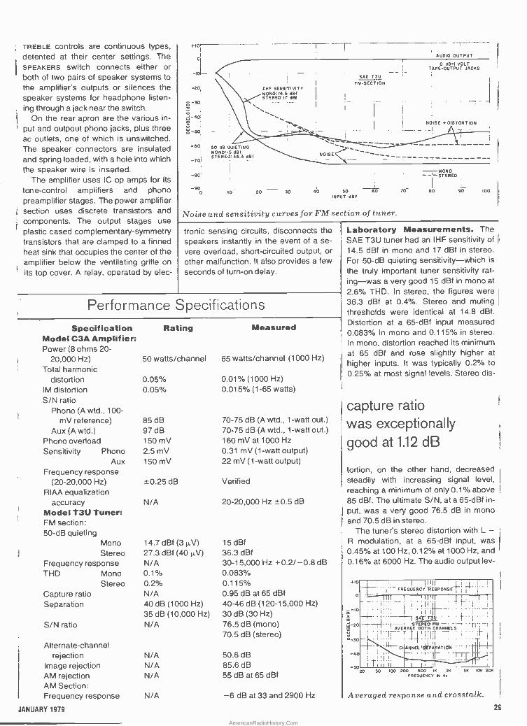
TREBLE controls are continuous types, detented at their center settings. The SPEAKERS switch connects either or both of two pairs of speaker systems to the amplifier's outputs or silences the speaker systems for headphone listen- ing through a jack near the switch.
On the rear apron are the various in-
put and outpout phono jacks, plus three ac outlets, one of which is unswitched. The speaker connectors are insulated and spring loaded, with a hole into which the speaker wire is inserted.
The amplifier uses IC op amps for its
tone -control amplifiers and phono preamplifier stages. The power amplifier section uses discrete transistors and components. The output stages use plastic cased complementary -symmetry transistors that are clamped to a finned heat sink that occupies the center of the amplifier below the ventilating grille on its top cover. A relay, operated by elec-
-10
-20
-30
- 4O
Wo -50
-60
-7DI
- 80
-90
r AUDIO OUTPUT
1L
IMF SENSIITIVITY MONO: 14.5 dB( STEREO'I7 del
50 de QUIETING MONO:15 del STEREO, 36.3 del
0 20 30
NOISE
0 dB=1 VOLT TAPE -OUTPUT JACKS
SAE T3U FM -SECTION
NOISE + DISTORTION
-- ,
; --- J-_ -__ ------------- I
40 SO 60 INPUT clef
Noise and sensitivity curves for FM section of tuner.
-MONO -STEREO ¡
70 - BÓ 90 100
tronic sensing circuits, disconnects the speakers instantly in the event of a se-
vere overload, short-circuited output, or other malfunction. It also provides a few
seconds of turn -on delay.
Performance Specifications
Specification Model C3A Amplifier: Power (8 ohms 20-
1 20,000 Hz) Total harmonic
distortion IM distortion S/N ratio
Phono (A wtd., 100 - mV reference)
Aux (A wtd.) Phono overload Sensitivity Phono
Aux Frequency response
(20-20,000 Hz) RIAA equalization
accuracy Model T3U Tuner: FM section: 50 -dB quieting
Mono Stereo
Frequency response THD Mono
Stereo
1
Capture ratio Separation
S/N ratio
Rating Measured
50 watts/channel 65 watts/channel (1000 Hz)
0.05% 0.05%
85dB 97dB 150 mV 2.5 mV 150 mV
-± 0.25 dB
N/A
14.7 dBf (31.1,V)
27.3 dBf (40 µV) N/A 0.1% 0.2% N/A 40 dB (1000 Hz) 35 dB (10,000 Hz) N/A
Alternate -channel rejection N/A
Image rejection N/A AM rejection N/A AM Section: Frequency response N/A
0.01% (1000 Hz) 0.015% (1-65 watts)
70-75 dB (A wtd., 1 -watt out.) 70-75 dB (A wtd., 1 -watt out.) 160 mV at 1000 Hz 0.31 mV (1 -watt output) 22 mV (1 -watt output)
Verified
20-20,000 Hz -0.5 dB
15 dBf 36.3 dBf 30-15,000 Hz +0.2/-0.8 dB 0.083% 0.115% 0.95 dB at 65 dBf 40-46 dB (120-15,000 Hz) 30 dB (30 Hz) 76.5 dB (mono) 70.5 dB (stereo)
50.6 dB 85.6 dB 55 dB at 65 dBf
-6 dB at 33 and 2900 Hz
Laboratory Measurements. The SAE T3U tuner had an IHF sensitivity of
14.5 dBf in mono and 17 dBf in stereo. For 50 -dB quieting sensitivity -which is
the truly important tuner sensitivity rat- ing -was a very good 15 dBf in mono at
2.6% THD. In stereo, the figures were 36.3 dBf at 0.4%. Stereo and muting thresholds were identical at 14.8 dBf.
Distortion at a 65-dBf input measured 0.083% in mono and 0.115% in stereo. In mono, distortion reached its minimum at 65 dBf and rose slightly higher at higher inputs. It was typically 0.2% to
0.25% at most signal levels. Stereo dis-
capture ratio was exceptionally good at 1.12 dB
tortion, on the other hand, decreased steadily with increasing signal level, reaching a minimum of only 0.1% above 85 dBf. The ultimate S/N, at a 65-dBf in-
put, was a very good 76.5 dB in mono and 70.5 dB in stereo.
The tuner's stereo distortion with L - R modulation, at a 65-dBf input, was 0.45% at 100 Hz, 0.12% at 1000 Hz, and '
0.16% at 6000 Hz. The audio output ley -
+10
0
- -10
-20 u °-30
-40
1 1 h I 1 I'' I
,
I1 1
I FREQUENCYREEuPONSE 11
' L ''.....` -+- i 1 1
1
ii. IL SAE' 1
STEREO FM 1 -1 1 AVERAGE BOTHICHANNELS
I, CI¡ANNELISEPAkAT10N
.1 f' II I I -5020
50 100 200 500 IK 2K FREQUENCY IN Hz
5K IOK 208
Averaged response and crosstalk.
JANUARY 1979 25
AmericanRadioHistory.Com
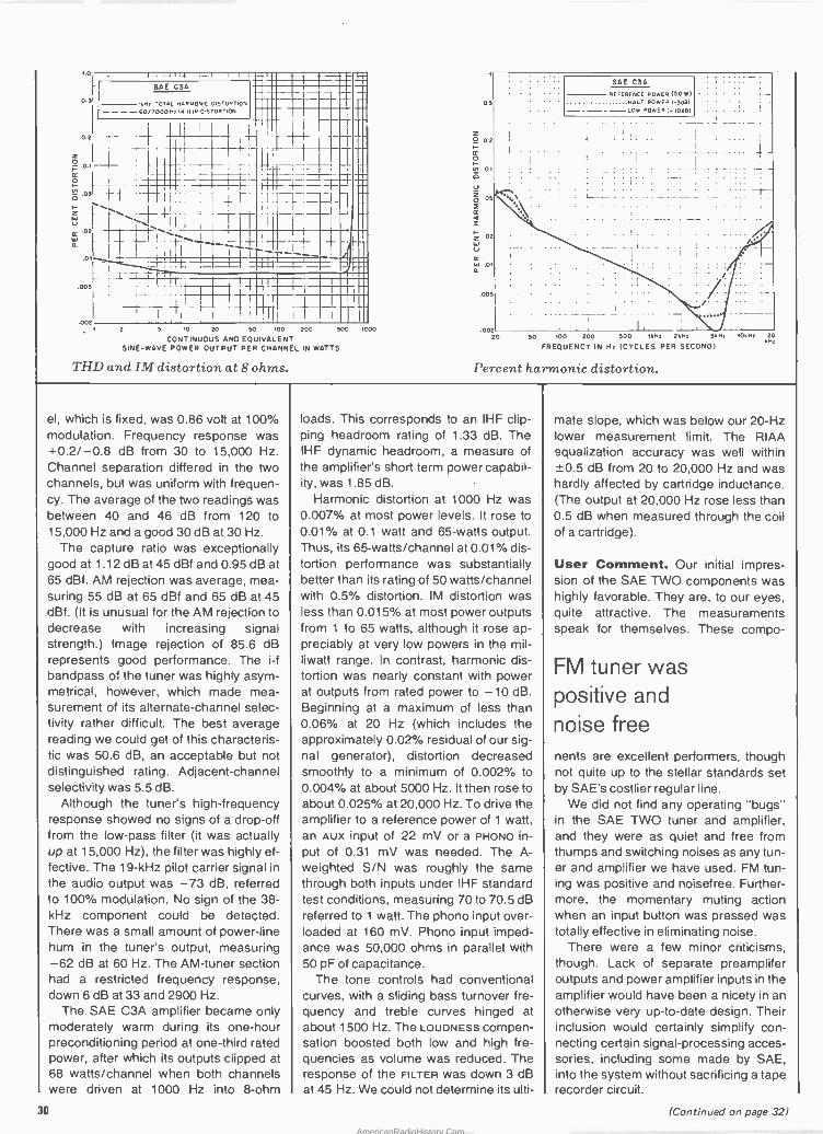
2 5 10 20 50 100 200
CONTINUOUS AND EQUIVALENT SINE -WAVE POWER OUTPUT PER CHANNEL IN WATTS
THD and IM distortion at 8 ohms.
500
0.5
2 02
0
.02
ú rc w .01 o.
.005
1000 00
SAE C3A
REDERENCE POWER (50W) MALI POWER (-3051 -----LOW POWER( -1005)
i
,. I
i I I I I I I
20 50 100 200 500 tM , 211, 540, 10th; 21
FR EOUENCY IN H2 (CYCLES PER SECOND)
Percent harmonic distortion.
el, which is fixed, was 0.86 volt at 100% modulation. Frequency response was +0.2/-0.8 dB from 30 to 15,000 Hz. Channel separation differed in the two channels, but was uniform with frequen- cy. The average of the two readings was between 40 and 46 dB from 120 to 15,000 Hz and a good 30 dB at 30 Hz.
The capture ratio was exceptionally good at 1.12 dB at 45 dBf and 0.95 dB at 65 dBf. AM rejection was average, mea- suring 55 dB at 65 dBf and 65 dB at 45 dBf. (It is unusual for the AM rejection to decrease with increasing signal strength.) Image rejection of 85.6 dB represents good performance. The i -f bandpass of the tuner was highly asym- metrical, however, which made mea- surement of its alternate -channel selec- tivity rather difficult. The best average reading we could get of this characteris- tic was 50.6 dB, an acceptable but not distinguished rating. Adjacent -channel selectivity was 5.5 dB.
Although the tuner's high -frequency response showed no signs of a drop-off from the low-pass filter (it was actually up at 15,000 Hz), the filter was highly ef- fective. The 19 -kHz pilot carrier signal in
the audio output was -73 dB, referred to 100% modulation. No sign of the 38 - kHz component could be detected. There was a small amount of power -line hum in the tuner's output, measuring -62 dB at 60 Hz. The AM -tuner section had a restricted frequency response, down 6 dB at 33 and 2900 Hz.
The SAE C3A amplifier became only moderately warm during its one -hour preconditioning period at one-third rated power, after which its outputs clipped at 68 watts/channel when both channels were driven at 1000 Hz into 8 -ohm
loads. This corresponds to an IHF clip- ping headroom rating of 1.33 dB. The IHF dynamic headroom, a measure of the amplifier's short term power capabil- ity, was 1.85 dB.
Harmonic distortion at 1000 Hz was 0.007% at most power levels. It rose to 0.01% at 0.1 watt and 65 -watts output. Thus, its 65-watts/channel at 0.01% dis- tortion performance was substantially better than its rating of 50 watts/channel with 0.5% distortion. IM distortion was less than 0.015% at most power outputs from 1 to 65 watts, although it rose ap- preciably at very low powers in the mil- liwatt range. In contrast, harmonic dis- tortion was nearly constant with power at outputs from rated power to -10 dB. Beginning at a maximum of less than 0.06% at 20 Hz (which includes the approximately 0.02% residual of our sig- nal generator), distortion decreased smoothly to a minimum of 0.002% to 0.004% at about 5000 Hz. It then rose to about 0.025% at 20,000 Hz. To drive the amplifier to a reference power of 1 watt, an AUX input of 22 mV or a PHONO in- put of 0.31 mV was needed. The A -- weighted S/N was roughly the same through both inputs under IHF standard test conditions, measuring 70 to 70.5 dB referred to 1 watt. The phono input over- loaded at 160 mV. Phono input imped- ance was 50,000 ohms in parallel with 50 pF of capacitance.
The tone controls had conventional curves, with a sliding bass turnover fre- quency and treble curves hinged at about 1500 Hz. The LOUDNESS compen- sation boosted both low and high fre- quencies as volume was reduced. The response of the FILTER was down 3 dB at 45 Hz. We could not determine its ulti-
mate slope, which was below our 20 -Hz lower measurement limit. The RIAA equalization accuracy was well within ±0.5 dB from 20 to 20,000 Hz and was hardly affected by cartridge inductance. (The output at 20,000 Hz rose less than 0.5 dB when measured through the coil of a cartridge).
User Comment. Our initial impres- sion of the SAE TWO components was highly favorable. They are, to our eyes, quite attractive. The measurements speak for themselves. These compo-
FM tuner was positive and
noise free nents are excellent performers, though not quite up to the stellar standards set by SAE's costlier regular line.
We did not find any operating "bugs" in the SAE TWO tuner and amplifier, and they were as quiet and free from thumps and switching noises as any tun- er and amplifier we have used. FM tun- ing was positive and noisefree. Further- more, the momentary muting action when an input button was pressed was totally effective in eliminating noise.
There were a few minor criticisms, though. Lack of separate preamplifer outputs and power amplifier inputs in the amplifier would have been a nicety in an otherwise very up-to-date design. Their inclusion would certainly simplify con- necting certain signal -processing acces- sories, including some made by SAE, into the system without sacrificing a tape recorder circuit.
30 (Continued on page 32)
AmericanRadioHistory.Com

New "customized" look! Model M-500 sidebody mount,
top loaded fiber glass whip with super performance.
JANUARY 1979
For over a quarter century, buying the very best CB antenna has meant buying Antenna Specialists. From superior materials, like resilient 17-7 PH stainless steel whips-to superior engineering, like the cool running coil in the famous "Big Momma"-these are the finest antennas money can buy. Only now you can buy them for less! Because your Antenna Specialists dealer is offering big 25th Anniversary savings on over a dozen of our newest and most popular models. It's a silver opportunity to move up to the stripes of quality... so see your dealer today!
ca
Ste pes oi ovamy.
the antenna specialists co. a member of The Allen Group Inc. 12435 Euclid Ave. Cleveland, Ohio 44106 Export: 2200 Shames Drive. Westbury. L.I.. NewYork 11590 Canada: A. C. Sirnmonds & Sons. Ltd. CIRCLE NO 6 ON FREE INFORMATION CARD 31
AmericanRadioHistory.Com

The calibration marks on the FM tun- ing dial are much too limited to permit unambiguous station identification. They appear to be reasonably accurate (though interpolating to 200 kHz accura- cy between markings spaced at 2 -MHz intervals calls for a combination of skill and luck).
Aside from the foregoing, we must say that the SAE TWO components per- formed very well. Also, we appreciated
that the FM tuner was noncritical in its setting for minimum distortion and max- imum channel separation. At most sig- nal levels, the center -channel tuning meter really did show the optimum tun- ing point for lowest distortion.
Although the Model C3A is not by any means a "super -power" amplifier, it has more than enough power for most instal- lations. We operated the tuner and am- plifier stacked, with the tuner on top, and CIRCLE NO. 102 ON READER SERVICE CARD
the amplifier hardly became warm, let alone hot. This is a positive benefit of a design that does not seek to cram every possible watt into a small package. The versatility ín installation afforded by this combination, plus their strikingly hand- some appearance and excellent sound, combine with a surprisingly modest price to make the Models C3A and T3U a fine SAE entry into the medium -cost component market. O
. {1
Y`. ,--rrry.
I 4. r r ,..........f ' ó ;- ,,,,,,,,.... ,"
II?, ' `.I
roe r' - :..
p p 0ó -s
two operating speeds are available in the new B. I. C. Model T-2 cassette deck
single -motor, two -head deck runs at 1 7/8 or 3 3/4 ips
HIRSCH- In the more than
HIRSC ten years since Philips introduced
F -A. s RT the "Compact Cassette," it has
been exclusively a 17/8-ips tape format for audio recording and playback. Philips licensing agreements have, until now, prevented any manufactur- er from entering the consumer market with cassette machines operating at other than 17/s ips. Philips' purpose has been to maintain full compatibility between all cassette recorders and tapes. Now, however, the situation has changed with the introduction of three new cassette decks from B.I.C. In addition to the usual 17/8-ips speed,
32
the "T" series decks can be operated at 3.4 ips. Just as with open -reel tape, doubling the tape speed makes possi- ble a substantial improvement in fre- quency as well as dynamic ranges as well as flutter.
The B.I.C. Model T-2 examined here is a single -motor, two -head, two - speed cassette deck with distinctive styling and unique operating features. Its black panel, with clearly legible white markings, contrasts with a rose- wood -finished wooden cabinet. The overall dimensions are 163/4"W x 6"H x 91/4"D (42.6 x 15.2 x 23.5 cm), while its weight is 12.8 lb (5.8 kg). Suggested retail price is $329.95.
General Description. At first glance, the Model T-2 appears to be quite conventional, though unusually handsome. The front -loading tape transport, with its bottom -hinged door, is at the left of the front panel. Piano -
key controls are below it and include a combined STOP/EJECT key. (Initial op- eration of this key stops the tape mo- tion, and the second opens the cas- sette compartment.) The tape must be at a stop before the PLAY, FAST FOR- WARD, Or REWIND controls can be op- erated. The cassette compartment's window is retained by two thumb- screws and can be removed easily for cleaning, demagnetizing, and adjust- ing the heads.
Just to the right of the cassette compartment is an index counter with a MEMORY button that can be set to stop the tape in REWIND when the counter registers 000. Two large, well - lit meters have black faces with back- lit white scale markings and white pointers that are exceptionally easy to read. Above 0 dB, the markings are in red. The meter scales are logarithmic and cover a range from -40 to + 5 dB, with the Dolby level calibration (corresponds to a 200 nW/m flux lev- el) at 0 dB.
Below the meters are two large con- centric knobs for setting recording lev- els for the two channels. A single in- dicator between the meters glows green when the deck is recording and instantly changes to red if the peak level exceeds 0 dB. A small OUTPUT LEVEL knob is located to the right of the meters, while below it is a sepa- rate PHONES LEVEL control that affects only headphone outputs.
doubling tape speed improves frequency and dynamic range
The remaining controls form a sin- gle row across the bottom of the pan- el, including a switch for selecting either 1 7/s- or 33/4-ips tape speed. The dc motor that drives the transport fea- tures tachometer feedback for speed
(Continued on page 38)
II
AmericanRadioHistory.Com

.. .
-1>1
P .a T.T 1 1,i..
:T I : II
.T` g
'Pr';-,.I;
z>I
T, `,,1`".1u
00
J
, 7
.....o __
,/, zo,,~r:-.11J.::"-.-1..5.;a!1,''u1. mr:91-0V 07.41 / 1
:> .o :.,
a_° 3 ,u ,S MI
lSWTal
r
,i
ICY
Someday all terminals will be smart....... 128 Functions-software controlled 7 x 12 matrix, upper/lower case letters 50 to 38,400 baud-selectable
82 x 16 or 92 x 22 format-plus graphics Printer output port "CHERRY" keyboard
CT -82 Intelligent Terminal, assembled and tested $795.00 ppd in Cont. U.S.
SOUTHWEST TECHNICAL PRODUCTS CORPORATION 219 W. RHAPSODY SAN ANTONIO, TEXAS 78216
JANUARY 1979 CIRCLE NO 50 ON FREE INFORMATION CART)
33
AmericanRadioHistory.Com

s`l
, :.,
*.) t
¡ lar áJ
i'...M nK M w_YfI.
,
I
When you do,you'll probably pick CIE. You can't afford to settle for
less when it comes to something like electronics training that could
affect your whole life.
34 POPULAR ELECTRONICS
AmericanRadioHistory.Com

When you shop around for tires, you look for a bar-
gain. After all, if it's the same brand, better price-why not save money?
Education's different. There's no such thing as "same brand." No two schools are alike. And, once you've made your choice, the training you get stays with you for the rest of your life.
So, shop around for your training. Not for the bargain. For the best. Thorough, profes- sional training to help give you pride and confidence.
* * * If you talked to some of our
graduates, chances are you'd find a lot of them shopped around for their training. They pretty much knew what was available. And they picked CIE as number one. Why you should shop around yourself.
We hope you'll shop around. Because, frankly, CIE isn't for everyone.
There are other options for the hobbyist. If you're the ambitious type -with serious career goals in electronics- take a close look at what we've planned for you at CIE.
(1 What you should look for first.
Part of what makes elec- tronics so interesting is it's based on scientific discoveries - on ideas! So the first thing to look for is a program that starts with ideas and builds on them!
That's what happens with CIE's Auto -Programmed° Lessons. Each lesson takes one or two principles and helps you master them -before you start using them! How practical is the training?
This is the next big impor- tant question. After all, your career will be built on what you can do - and on how well you do it.
1-iere are ways some of CIE's trouble- shooting programs help you get
you learn and review the basics- perform dozens of experiments. Plus, you use a 3 -in -1 precision Multimeter to learn testing, checking, analyzing!
r-
; 110i - f
_
When you build your own 5 MHz Triggered - Sweep, Solid -State Oscil- loscope you take your first real professional step. You use it as a doctor uses an X-ray machine-to "read" waveform patterns ... lock therm in .. .
study, understand and inter- pret them!
When you get your Zenith 19 -inch Diagonal Solid -State Color TV you
0
1*`F
your "hands-on" training .. .
With CIE's Experimental Electronics Laboratory...
simply this: All this training takes
effort. But you'll enjoy it. And it's a real plus for a trouble- shooting career! Do you prepare for your FCC License?
Avoid regrets later. Check this out before you enroll in any program.
For some troubleshooting jobs, you must have your FCC License-. For others, employers often consider it a mark in your favor. Either way, it's govern- ment -certified proof of specific knowledge and skills!
More than half of CIE's courses prepare you for the government -administered FCC License exam. In continuing surveys, nearly 4 out of 5 CIE graduates who take the exam get their Licenses!
Pat tern sinwlated. apply your new skills to some real on -the -job -type trouble- shooting! You learn to trace signal flow... locate malfunc- tions ... restore perfect operat- ing standards-just as with any sophisticated electronics equipment!
0.0.4 uN.,,pll .
Ebel. I ,.. Clpa; -
When v you work with a completely
Solid -State Color Bar Generator- actually a TV signal transmitter-you study
up to ten different patterns on your TV
screen ... explore digi- tal logic circuits ... observe
the action of a crystal -con- trolled oscillator!
Of course, CIE offers a more advanced training pro- gram, too. But the main point is
Shop around ...but send for CIE's free school catalog first:
Mail the card. If it's gone, cut out and mail the coupon. If
you prefer to write, men- tion the name and date of this magazine. We'll send you a copy of CIE's FREE school catalog - plus a complete pack- age of independent
home study information! For your convenience, we'll try to have a repre- sentative contact you to answer your questions. Mail the card or coupon - or write: CIE, 1776 East 17th St., Cleveland,
OH 44114. r--- MI Ell I= MI C 1 E Cleveland Institute
of Electronics Inc. II1776 East 17th Street, Cleveland. Oho 44114
Acredt.a Member Nelienel Nome Sway coe,c,l ' YES ... I'm shopping around for the right kind of career training in electronics troubleshooting-and CIE sounds well worth looking into. Please send me my FREE CIE school
la catalog- including details about Ill troubleshooting courses-plus my
FREE package of home study information!
1
PE -81
Print Xamc
Address Apt
City
State Zip
Age Phone (area code)
Check box for G.I. Bill information: O Veteran ú Active Duty
Mail today: 37
AmericanRadioHistory.Com

(Continued from page 32)
regulation. A RECORD SAFETY Switch has three positions, labelled SAFE, READY, and MUTE. This switch oper- ates in addition to the mechanical RECORD switch associated with the transport keys and the recording safe- ty tabs on the cassette, which prevent the RECORD key from being engaged when they are removed. In the SAFE
position, the deck will not record or erase, no matter how the other con- trols are set. In READY, the recorder operates in a conventional manner, under the control of its RECORD and PLAY keys. MUTE is spring -loaded and can be used to blank out unwanted material (such as commercial an- nouncements) while making a record- ing. Holding it down allows the deck to continuously erase the tape, with no signal being recorded. Releasing it re- stores normal recording. A DOLBY/ MPX switch is also provided. In its bot- tom position, the Dolby system is off. Setting it to the center position, turns on the Dolby system and a green LED above the switch. In the top position, a multiplex (MPx) filter is inserted in the signal path to prevent an FM tuner's pilot carrier leakage from influencing the operation of the Dolby system.
Separate switches control bias and equalization. The three BIAS positions are labelled HI, NORM, and Lo, while the Eo settings are marked in terms of their time constants (70 and 120 µs). In general, HI bias is for chromium - dioxide or equivalent tapes, while good ferric -oxide tapes will require NORM bias. Lo bias is presumably for relatively inexpensive, low -perfor- mance tapes.
To the right of the recording level knobs is a pushbutton switch that per- mits selection of either the LINE or the mic inputs for recording. (The two cannot be mixed.) Next in line to the right is the PHONES jack.
Laboratory Measurements. The recorder had been factory adjusted for TDK AD and SA tapes (NORM BIAS and 120-µs EQ; HI BIAS and 701.Ls Ea). Hence, we used these tapes for all our tests. Insofar as possible, all mea- surements were made at both tape speeds. Following the information supplied with the recorder, we used HI
bias for both tapes at 33/4 ips, although the EC) time constants were the same at both speeds.
The line inputs at the rear apron re- quired only 31 mV at 1000 Hz for a 0 -dB meter indication. The corre-
sponding maximum playback level was about 1.8 volts. MIC sensitivity was 0.165 mV, and the microphone preamplifier overloaded with a 21 -mV input. This indicates the need for cau- tion when recording from micro- phones, any of which can deliver over 21 mV at reasonably high sound lev- els. The maximum headphone output was 1.5 volts into 200 ohms, which gave a very comfortable listening level with medium -impedance phones.
red indicator is most informative display for overload seen
The 1000 -Hz playback distortion with a 0 -dB recording signal level was well below the specified limits with SA tape and extremely low (0.25% to 0.5%) with AD tape. The reference re- cording level for AD tape, correspond- ing to 3% playback distortion, was +5 dB at 1'/a ips and +7 dB (well above the meter scales) at 33/4 ips. As ex-
pected, the SA 70-µs tape saturated at a lower level, +3 dB at 17/s ips and +4 dB at 33/4 ips. The red OVERLOAD indicator came on at +1 dB, well be- fore the onset of significant distortion with either tape.
The unweighted S/N, referred to the 3% distortion signal level, was about 48 dB at the lower speed and 51 dB at the higher speed with both tapes. With A weighting, it was 57 to 57.5 dB at 1'/8 ips. At 33/4 ips, the dif; ference between the two tapes was revealed, with AD measuring 61.2 dB and SA 62.4 dB. When we used the Dolby system with CCIR/ARM noise weighting, the S/N performance was very good. It was 64.2 dB with AD tape and 63.6 dB with SA tape, both at 178 ips. At 33/4 ips, S/N was 66.8 dB for AD and 69 dB for SA tape.
The 120-11s playback equalization was measured with a TDK AC -337 test tape. It was flat within ±0.5 dB from 90 to 4000 Hz, and rose to +3.4 dB at 40 Hz and +2.2 dB at 12,500 Hz. The 70-1.Ls response from a Teac 116SP tape was within ±0.5 dB from
Performance Specifications
Specification Speeds
Frequency Response 70 µs: 1 7/s:
33/4:
1201.1.s: 17/8:
33/4:
S/N (A weighted, ref. 3% THD, 70 µs) 1N: 33/4:
1 7/s (Dolby): 33/4 (Dolby):
Wow and Flutter 17/8 (wrms): 33/4 (wrms): 1'/s (wpk/DIN): 33/4 (wpk/DIN):
THD (0 dB, 70µ,$): 1/s: 33/4:
(0 dB, 120 µs):1 V/s:
33/4:
Fast Forward/Rewind Meter Type Meter Range Output (line) Input (line)
Microphone Overload
Rating 1 /s ips (4.75 cm/s) 334 ips (9.5 cm/s)
30-18,000 Hz ±3 dB 30-21,000 Hz ±3 dB
NA NA
54dB 57dB 62 dB 66 dB
0.06% 0.04% 0.12% 0.10% 1.9% 1.6% NA
Approx. 48 seconds Peak indicating -40 to +5 dB
2.0 V rms into 10,000 ohms 200 mV for 0 -dB indication
NA
Measured
20-15,500 Hz ±2 dB 20-25,000 Hz ±3.5 dB 20-15,000 Hz ±1.5 dB 20-24,400 Hz ±3.5 dB
57.5 dB 62.4dB 63.6 dB (CCIR) 69.0 dB (CCIR)
0.06% avg. 0.04% (R/P) 0.10% 0.06% (R/P) 1.1% 0.8% 0.56% 0.25%
51 seconds Confirmed Confirmed
1.8 V
31 mV line 0.165 mV mic.
21 mV
38 POPULAR ELECTRONICS
AmericanRadioHistory.Com

. vi
Get the inside story... on software, hardware, simulations, computer games, robotics, computers and calculators, languages and compilers, custom systems design and scores Imib, mm® of applications. Read BYTe BYTE, the leading magazine in the personal computer field, will keep you aware of fast -paced changes in the ever growing world of micro- processors. You'll find BYTE tutorials invaluable, reports on home com- puter applications instructive, and the reviews of computer products stimulating.
Tutorial information in BYTE is of interest to both the beginner and
Fill in and mail the coupon today. Read your first copy of BYTE. If it is everything you expected, honor our invoice. If it isn't, just write "Cancel" on the invoice and mail it back. You won't be billed and the first issue is yours at no charge.
Allow 6 to 8 weeks for process- ing. If you have any questions, dial toll free 800-258-5485. This is the number of the BYTE Subscription Department.
BYTE and BYTE logo are trade- marks of BYTE Publications, Inc.
© BYTE Publications, Inc.1978 L
experienced computer user. BYTE's editorial content explores the fun of using and applying computers for personal satisfaction in activities from electronic music to electronic mail, from games to pragmatic personal business. In BYTE is found authoritative yet easily read cov- erage of principles of computer hardware and software design, approaches to novel applications,
and essentials of proven interest to personal computer enthusiasts.
Each month serious computer users read BYTE. They're rewarded with timely articles by profes- sionals, computer scientists and competent amateurs. Isn't it time you got the inside story? Subscribe now to BYTE, the Small Systems Journal.
BYTE Subscription Dept. P.O. Box 590 Martinsville, NJ 08836 Please enter my subscription for
One year $15 (12 issues) Two years $27 Three years $39 Send group rate information Check enclosed entitles me to 13 issues for price of 12 (North America only) Bill Visa Bill Master Charge O Bill me (North America only)
Card Number Expiration Date
Signature
Address
Name (please orint)
City State/Province/Country Code
Foreign Rates (To expedite service, please remit in U.S. Funds) Canada or Mexico O One year $17.50 Two years $32 Three years $46.50 Europe, one year (air delivered) $25
O All other countries, one year (surface delivered) $25. Air delivery available on request. 7319 CIRCLE NCi. 10 ON FREE INFORMATION CARD
39 JANUARY 1979
AmericanRadioHistory.Com

Eºop -.... $
BIC PLAYBACK
T-2
!E:
RESPONSE
I TO Py (TE!AC 116 SP)
!- li L
I i 1
FREQUENCY (Hz) 10 00
Playback response on test tapes with 120 and 70 microsecond equalization.
T -- 5dB '
____.. ._ .:. . . . .. . ....
.. _-..: 2iC T 2
PLAYBACK R6,SPONS 2/B IPS
_ ..- . 20 dB
' 11116111181 I ailill':11II
o J .
FREQUENCY (Hz)
-1-
Record/playback response for TDK AD and SA tapes at 1% ips.
it
0 00
-- -- 5dB _L.
I
BIC T-2 LAYBACK RESPONSE -3/4 IPS
1.
.,.f.:: 5 R I B
FREQUENCY (Hz)
l:
--- z-- .. .
-.-
-H GH BIAS
IT(
D H GH BIAS/1 ¡G-prf9:== T SA i Ea::
Record/playback response for TDK AD and SA tapes at 344 ips.
10 00
63 to 4000 Hz and rose to +2.4 dB at 40 Hz and +1.7 dB at 10,000 Hz.
Record/playback frequency re- sponse with TDK AD tape at 1741 ips (measured at a -20 -dB level) was ±1.5 dB from 20 to 15,000 Hz. The re- sponse "ripples" at low frequencies, though present, were much less no- ticeable than on most cassette record- ers. B.I.C's T-2 was unusual in main-
taining its full performance down to 20 Hz. High frequencies rolled off fairly gently above 15,000 Hz, to -7.5 dB at 20,000 Hz. At a 0 -dB recording level, the effects of tape saturation were hardly detectable below about 7000 Hz, and the 0 -dB response curve in- tersected the -20 -dB curve at 15,000 Hz. (This intersection usually occurs around 11,000 to 12,000 Hz.)
Performance with TDK SA tape was generally similar, although there was a slight response rise at 10,000 Hz and slightly better output at the high- est frequencies. The overall response was ±3 dB from 20 to 19,000 Hz. The 0 -dB curve intersected the -20 -dB curve at 15,500 Hz.
When we measured the record/ playback response at 33/4 ips with AD tape, we found a substantial improve- ment. (Although it was predictable and expected, it was nonetheless highly impressive.) The response was within ±3.5 dB from 20 to 24,400 Hz at -20 dB, and the 0 -dB curve was virtually flat up to 13,000 or 14,000 Hz, intersecting the -20 -dB curve at 20,000 Hz. With SA tape, the re- sponse was fairly similar, and was within ±3.5 dB from 20 to 25,000 Hz at -20 dB. The 0 -dB response satu- rated earlier than that of the AD tape. The curve began to drop at 10,000 Hz, but it intersected the -20 -dB curve somewhere above 20,000 Hz.
Dolby tracking was unusually close. The change in frequency response, when the Dolby system was switched in and out, was less than 1 dB up to about 12,000 Hz and less than 2 dB at 15,000 Hz, at recording levels of -20 and -40 dB. The meters indicated ex- actly 0 dB (the Dolby level) when we played a standard Dolby level calibra- tion cassette. Unlike many low-priced recorders, the meter calibrations here were exceptionally accurate (an input change of "X" dB produced a closely corresponding change in the meter in- dications). With 0.3 -second tone bursts used to check VU -meter ballis- tics, the Model T -2's meters indicated the same as with a steady-state sig- nal. On program input, we could see that the meters had a fast rise time, followed by a much slower decay, so that they tended to follow the peak program level.
The 1'/B-ips speed drifted slightly, from 0.5% fast at one end of a cas- sette to 0.15% fast at the other end. (We made no speed measurements at 33/4 ips.) Using a TDK AC -342 flut- ter test tape, we measured the CCIR (weighted peak) flutter at a very good ± 0.1%. The JIS (weighted rms) flutter varied from 0.05% to 0.07% at the two ends of the cassette. In a combined record/playback flutter measurement, the CCIR and JIS flutter readings were respectively ±0.12% and 0.09% at 17/s ips. At 33/4 ips, they measured ± 0.06% and 0.04%. These figures
40 POPULAR ELECTRONICS
AmericanRadioHistory.Com
would do justice to a good open -reel
recorder! In fast forward and rewind modes, the transport moved a C-60 cassette from end to end in 51 sec- onds, which is considerably above av-
erage for a cassette deck.
User Comment. The B.I.C. Model T-2 demonstrated superb perfor- mance at 33/4 ips. But we were equally impressed by what it did at 17/8 ips! Af-
ter all, the limitations of the cassette medium begin to decrease rapidly when the speed is doubled. Hence, we were not so surprised by what we
measured at 33/4 ips (although the prospect of frequency response, S/N, and flutter levels approaching or matching those of a costly three -head cassette deck is certainly attractive).
Considering the T-2 solely as a con- ventional 17/8-ips cassette deck, it is
one of the better values we have seen in some time. In many ways, it is a "no frills" machine, with a single motor, combination record/playback head,
completely mechanical transport con- trols, and no input mixing capability. On the other hand, it has superb me-
ters, whose dynamic range and re-
sponse characteristics give the user a
much clearer idea of what the pro- gram is doing than run-of-the-mill re-
corder meters. The manner in which the green RECORD indicator instan- taneously changes to red at a +1 -dB level might seem to be a rather minor "gimmick," but we found it to be by far the most visible and informative over- load indicator we have seen on a tape deck. It simply cannot be ignored or confused with any other indication. Perhaps its only weakness is that it
flashes far below the true overload level of AD tape, but it is nearly ideal
for use with SA tape. When we recorded interstation FM
tuner hiss at -20 dB on AD tape, the
playback was almost indistinguish- able from the input signal. (There were minute differences, but one must listen very closely to detect them.) By
increasing the speed to 33/4 ips, we
could record at meter readings of -2 dB, with the red overload indicator flashing regularly, and hear only about the same small amount of degrada- tion in the high -frequency response. At -10 dB, the reproduction was per- fect. In our experience, this is uniquely fine performance for a two -head cas- sette deck. In practical terms, this means that the Model T-2 is much less likely to compress the high-level
JANUARY 1979
peaks and produce a dull or "mushy" sound, especially when recording from a live source, than almost any other comparably priced cassette re-
corder. Unfortunately, one must also con-
sider the limitations of a cassette op-
erating at 33/ ips. Operating times are halved, so that even a C-90 cassette plays only about 23 minutes on a side.
One would think that a C-120 would
be an ideal solution to this problem, since it would be the equivalent in re-
cording time of a C-60 operating at
17/f3 ips. However, B.I.C. specifically and categorically states that the Mod-
el T-2 should not be used with C-120 tapes, both because of their magnetic and physical properties and because the high-speed rewind and fast for-
ward of the transport could damage very thin tapes.
Even if one finds C-90 tapes satis- factory, there is the question of com- patibility. At this time, B.I.C. is the only
company making a 33/4-ips cassette recorder. This means that tapes made
on a B.I.C. machine at 33/4 ips can be
played only on a B.I.C. machine, at
least for the immediate future. Fur-
thermore, even if other companies go
to the higher speed, there is no assur- ance that they will adhere to the
equalization standards chosen by
B.I.C. Finally, there is the imminent commercial introduction of metal par- ticle tapes and recorders capable of
using them. Although they are expen- sive -at least for the present -these tapes have the potential of giving much of the performance at 11/s ips
that B.I.C. achieves at 33/4 ips, without sacrificing any playback compatibility with existing cassette decks.
Thus, we prefer to consider the B.I.C. Model T-2 as an especially good cassette recorder, with perfor- mance well above the normal for its
price range. It also has a higher speed operating mode that may well give it
the best cassette performance capa- bility at this moment in time. CIRCLE NO. 103 ON READER SERVICE CARD
Correction: In the report on the Signet
Model TK7E stereo phono cartridge, in the November issue, the channel separation at
1 kHz should be 30 dB, as shown in the graph, rather than 20 dB, as given in the
Performance Specification chart.
BLANK TAPES & ACCESSORIES
AT WHOLESALE PRICES!
BLANK TAPES CASSETTE TAPES
Amp. Grand Master I C.60 . 52.14 Amp Grand Munr I C.90 . $2.)9 BASF Studio C.90 52.69 BASF Protessional
II or III C.90 5299 Maxell UD C-60 51.93
=i Maxell UD C.90 . . . . . . . . 52.84 M.x.11 UDXL I or II C.60 52.47
o c tclh 1 no!» C-90
r II C.90 53.47 -
C-90 / 3 pk 51.99 for 3 Scotch Macho I C-90 ......52.84 Scotch.Mes,er II or III C.90. 53.29 Sony F.rrx:hrom. C-90 . . . . 53.58
TDK D C-60 51.20 TDK D C.90 51 68 TDK D C-120 52.10 '
TDK 0 C.180 52.99 MEAD C.60 51.79 ' TDK AD C.90 52.52 TDK SA C.60 52.22 TDK SA C.90 53.18
REEL-TO-REEL Mex.11 00 35-90 1800 $5.49' Max.11 0001. 35.908 18001, 56.62 ` M.11 UD 35180 3600 ft.
1x.10F"1 514.7 0 .
Scotch 212 1800 f,. . 54.35 °
Scotch 207 1800 ft 55.19 TDK 1..1800 1800 ft 55.22
Minimum Order 12 Tapes - 100% Guaranteed.
CauadióRIDGES á.
AT -20 SLA . . . . 5119.00 . AT.15 SA
AT.14 SA
61.12 SA
T-10 s1ANTON
8815. 7250 681EEES 55.00 68 1 E E E . . . .. . . . . . . 42.50 680EE.. ..... .. 20.80 500EE 1440
582.50 546.50 534.90 512.00 015 TYPE IV 589.90
015 TYPE III 563.50 ' M9SED 526.50
521.00 1424HDIOUA01 536.50 M)OEJ 59.90
E119IFE 20002 559.90 20001 531.50 2000E111. 519.50 4000131 929.90
- .C---^-- KUV/45000IOUADI 566.00 " XSV/3000 545.95 ' xV15f750E 530.00 0015/625E .... ... 520.98 0015/400E 517.95
HEADPHONES CO PIONEER
n .5 1-117.10=1E '
.
KOSS 1 '
PRO 4AA S37.05 SE.205 519.95 PRO 4 AAA $45.00
. SE.505 S46.70 HV/1 526.97 SE -4 533.50 HV/ILC 535.97 SE 500 539.95 PHASE/2e2 593.00 SE.700 55995 TECHNICIAN/0F8 S46.00
Q3.5~41EISEp 0/6A . 514.97
110.400 524.99 W /413.414539.97 ra - HO 424 559.95 OA.7 541.90
HOW TO ORDER: For shipment within 48 hours. send money order of certified check. Two Weeks delay on personal checks. Please add 53.50 per rder for shipping & handling. ($5.50 for orders outside U.S.I. N.V.S. residents add tax. No C.O.D.'s. All merchandise 100% guaranteed, brand new & factory fresh.
MUSIC WORLD}
33 Palk Row, Dept. PE, N.Y.C. 10038 (2121132.8600
WRITE FOR FREE CATALOG -
C RCLE NO. 30 ON FREE INFORMATION CARD
Put Professional Knowledge and a
COLLEGE DEGREE in your Electronics Career through
Earn Your
DEGREE by correspondence, while continuing your present job. No commuting to class. Study at your own pace. Learn from complete and explicit lesson materials, with additional assistance from our home -study instructors. Advance as fast as you wish, but take all the time you need to master each topic. Profit from, and enjoy, the advantages of directed but self -paced home study.
The Grantham electronics degree pro- gram begins with basics, leads first to the A.S.E.T. degree, and then to the B.S.E.T. degree. Our free bulletin gives complete details of the program itself, the degrees awarded, the requirements for each degree, and how to enroll. Write for Bulletin E-80.
Grantham College of Engineering 2000 Stoner Avenue
P. O. Box 25992
Los Angeles, CA 90025
Worldwide Career Training thru Home Study CIRCLE NO. 23 ON FREE INFORMATION CARO
AmericanRadioHistory.Com

IF YOU'RE NOT DESIGNING WITH ACSC PROTO-BOARDLOOK
ATALLYOU'RE MISSING. Utility-Models are available with or without built-in regulated power supplies (fixed or adjustable).
Economy-Eliminate heat and mechanical damage to expensive parts. Save money by re -using components.
Versatility-Use with virtually all types of parts, including resistors. capacitors, transistors, DIP's, TO -5's. LED's, transformers. relays. pots, etc. Most plug in directly, in seconds.
Durability-All Proto-Board models are carefully constructed of premium materials, designed and tested for long, trouble -free service.
Expandability- Proto-Board units can be instantly inter- connected for greater capacity.
Visibility-All parts are instantly and easily visible, tor quick circuit analysis and diagramming.
Speed-Assemble. test and modify circui as fast as you can push in or pull out a lead. Save hours on every project.
Adaptability-Use in design packaging, inspection, OC, etc. Works with most types of circuits. in many, many applications.
Accessibility-All parts are instantly and easily accessible: for quick signal tracing, circuit modifications, etc.
Flexibility-Use independently, or in conjunction with other accessories, such as scopes, counters, CSC Proto-Clip" connectors, Design Mate test equipment, etc. One Proto-Board unit can serve a thousand applications.
Ordertoday. Call 203-624-3103 (East Coast) or 415-421-8872 (West Coast): 9 a.m.-5 p.m. local time. Major credit cards accepted.
Or see your CSC dealer. Prices slightly higher outside USA.
CONTINENTAL SPECIALTIES CORPORATION =0= 70 Fulton Terrace, Box 1942, New Haven, CT 06509
203-624-3103 TWX 710-465-1227 WEST COAST: 351 California St., San Francisco, CA 94104,
415-421-8872 TWX 910-372-7992 GREAT BRITAIN: CSC UK LTD., Spur Road, North Feltham Trading Estate,
Feltham, Middlesex, England, 01-890-0782 Intl Telex: 851-881-3669
Variety-A wide variety of models are available with capacities ranging from 630 to 3060 solderless tie -points (6 to 32 14 -pin DIP'S), to fit every technical and budget requirement.
Whatever type of electronic circuits you
work with, you can do more in less time with
CSC's solderless Proto- Board systems. As fast and
' easy as pushing in or pulling out a lead, you can design, test and
modify circuits at will. Com- ponents plug into rugged 5 -point
terminals, and jumpers, where needed, are lengths of #22 AWG
solid wire. In the same time you took to read this ad, you could be well on
your way to assembling a new circuit.
CSC PROTO-BOARD SOLDERLESS BREADBOARDS
MODEL NUMBER
NO. OF SOLDERLESS TIE -POINTS
IC CAPACITY (14 -PIN DIP'S)
MANUFAC. SUDO. LIST
OTHER FEATURES
PB-6 630 6 $15.95 Kit -10 -minute assembly
PB-100 760 10 19.95 Kit-with larger capacity
PB-101 940 10 22.95 8 distribution buses, higher capacity
PB-102 1240 12 26.95 Large capacity, moderate price
P8-103 2250 24 44.95 Even larger capacity; only 2.70 per tie -point
PB-104 3060 32 54.95 Largest capacity; lowest price per tie -point
P8-203 2250 24 75.00 Built-in 1% -regulated 5V, 1A low -ripple power supply
PB-203A 2250 24 124.95 As above plus separate V2 -amp +15V and -15V internally adjustable regulated power supplies
42
© 1978 Continental Specialties Corp. Prices and specifications subject to change without notice.
CIRCLE NO. 14 ON FREE INFORMATION CARD
POPULAR ELECTRONICS
AmericanRadioHistory.Com

By KRIS JENSEN
A buyer's guide to
projection TV
receiver systems The BIG television picture is bigger than ever now as a result of techno-
logical advances in video projection sys- tems. Projection TV is not new, of
course. In the late Forties, when TV pic-
ture tubes were still rather small, all -in -
one TV projection systems were intro-
duced in the hope of displacing direct - view receivers. Low brightness and the
development of larger TV CRTs, how-
ever, dampened the projection concept for home use.
Two decades later, the Advent Corpo- ration resurrected the projection -TV
concept with a newly developed very -
large -screen system that dwarfed pre-
sent-day TV picture tube viewing areas
without noticeable loss of brightness or
resolution. Local bars and well-to-do people were among the first buyers in
1973 of the large -screen (7' diagonal),
two-piece, Model 1000 color projection
-
r . I i 4-
t I T¡
Electronics JANUARY 1979
H.e di
olor
BigPic'.e is Here!
ri_
17' ® - .::i .,. r 1-`,++i` e
1
i.r A ' , deb'{A.
-
_. . ';"n-L
Thy + . ;.` . . C 3 . t y .
JANUARY 1979 43
AmericanRadioHistory.Com

Home Projection TV continued
TV system. A smaller, lower -cost, 5' di- agonal screen model is now also being marketed by Advent, competing with some 50 other manufacturers of home projection -TV systems. These compa- nies-including GE, Panasonic, and Quasar-produce a variety of projec- tion -TV models at prices ranging from $400 to more than $3000. Clearly, giant - size color TV for the home has arrived!
Projection -TV systems receive stan- dard off -the -air TV signals, but they dif- fer enormously from the standard 25" (63.5 -cm) console receiver. The funda- mental difference is that the video image you see is not produced directly on a
conventional picture tube. Instead, the image is magnified, projected onto a
giant 45" to 120" (diagonal measure- ment) viewing screen. This projection scheme gives you a movie -house effect right in your living room.
Just how the picture is produced by each of the many projection -TV systems available varies. Physically, these new home -entertainment devices can range
PROJECTION SCREEN
MIRROR / i
LENS
"i10
from two-piece systems in which the projector hangs from the ceiling to all -in - one compacts that close up into a wall unit when not in use. The optical tech- niques employed give picture qualities that range from fair to excellent.
In spite of the differences in system design, there are only three main cate- gories in projection -TV schemes: refrac- tion, Schmidt, and light -valve. Each ren- ders a projected image with its own par- ticular tradeoffs.
Refraction Systems. If you hold a
magnifying glass up to the face of your TV receiver, you can focus the magni- fied image on a nearby wall. In doing so, you create a basic refraction, or all -lens, projection -TV system. Light from the pic- ture tube passes through the lens and is
bent (refracted) outward to provide the magnification. This is the simplest and most commonly employed technique for projection. There are, however, two types of refraction projectors. The first is
the single -tube -system, which uses an "almost" conventional TV receiver as the image source and a separate magni- fying lens.
In some single -tube projection sys- tems, the lens is merely bolted directly to the face of the receiver. For others, some type of enclosure is used to house
c `^
the TV receiver and support the lens. In
any event, the results are the same. Light from the image on the TV screen is
gathered at the back of the lens, refract- ed, and sent out the front of the lens. This light is then focused on a reflective screen for viewing some 5' to 8' (1.5 to 2.4 m) away.
Light passing through the lens from the TV receiver is inverted in the refrac- tion process. To correct for this inver- sion, a minor modification must be made to the TV receiver. Wires on the receiv- er's yoke are transposed to invert the original picture on the face of the tube. (The yoke is a coil of wire on the neck of the picture tube that causes the electron beam to scan across the face of the tube.) A switch is usually provided to flip the picture back for normal viewing. Once the inverted image in the projec- tion mode passes through the lens, it is
inverted so that it appears right -side up for normal viewing on the screen.
Brightness deficiency is a major con- sideration for many refraction -lens sys- tems. As a result, you must watch the screen in virtual darkness in order to ob- tain a good picture.
There are two major reasons for the lower light level in refraction systems. The first is the optics themselves. Lenses are nowhere near perfect in effi- ciency. Not all the light that enters them passes out again. Some of the light is
scattered into useless heat energy with -
.
Self-contained type of projection TV, such as the Sony Corp. model above right, uses mirror to reflect enlarged TV image to face of viewing screen.
tt 4,1 1011a. `:..
b
44 POPULAR ELECTRONICS
MR I AmericanRadioHistory.Com

in the lens. Too, a part of the light spec- trum may never get through the lens. Also, the light -gathering efficiency of a
lens is determined by the lens' F rating. Like the F-stops of a camera, the lower the F number of a projection -TV lens, the more light that passes through. The type of lens used in a single -tube projec- tor often accounts for price. Typically, the lower the cost, the higher the F num- ber (and the lower the light level avail- able for imaging on the viewing screen).
The second and by far the greater problem is the TV receiver itself. For each degree of magnification you gain, you pay a price in light loss. If you pro- ject a magnified picture twice its normal size, for instance, you may require 10
times the amount of light coming from the picture -tube source to compensate for the loss of brightness on the screen.
Some manufacturers increase drive voltage on the picture tube of a conven- tional TV receiver in an attempt to
achieve a brighter picture. Although this can certainly be done, it can have detri- mental effects on picture quality. Since the total picture is brightened, blacks be- come shades of grey, causing a loss in
contrast and, depending on the receiver, image blooming that can render the pic- ture out of focus.
Naturally, there are exceptions to the foregoing. Some projection -TV receiv- ers are specifically designed for projec- tion use. A good example of this is the 13" (33 -cm) in -line picture tube in GE's 45" diagonal Widescreen 1000, which is
driven by 32,000 volts. To combat the problems inherent in
single -tube systems, some manufactur- ers have gone to multiple -tube designs and better optics. The idea here is to substantially increase the available light
Two-piece, single - refraction -lens models, such as
Projection Electronics'
here, are least costly types
I ,
level without degrading picture quality. These systems employ three projection CRTs (cathode-ray tubes), each of which consists of an electron gun that scans a small phosphor -coated screen. The image produced on the screen is
then magnified by a front lens and pro- jected onto the viewing screen. While it
is easy to see why three tubes give off more light than one, the reason for a
much brighter picture goes far beyond simple light multiplication.
In a normal color picture tube, the total color picture is produced on the face of the screen. To accomplish this, triads of red, green, and blue phosphors must be kept close together to form a particular color. To prevent one gun from exciting all three colors simultaneously, a shad- ow mask is used. The mask allows only the correct color -generating gun to strike the appropriate phosphor. Though the mask serves its purpose for convention- al viewing, it poses a problem for projec- tion -TV applications. It cuts down the energy from the electron guns by as much as 80%. Only 20% of the available energy is converted into usable light.
In a three -tube projection system, each tube produces just one color. The "mixing" occurs on the screen so that no
shadow mask is required in the tubes. The result is a picture with four or five times the brightness obtainable from most conventional single -tube systems.
In addition to increased brightness, picture quality is usually enhanced in
three -tube systems. Convergence, where the three color dots are exactly mixed to form the desired color, is also less of a problem. In contrast, any mis - convergence in a single -tube system is
exaggerated by magnifying the total pic- ture. Sharp, clear outlines of images be-
come lost, and in extreme cases multi- ple different color images can appear superimposed on but slightly offset from
each other. With respect to selling prices, single -
tube systems are by far the least expen- sive. If you choose a three -tube system, though, you can expect to pay two to
three times the cost of a single -tube sys- tem. Sony, however, is attempting to
capitalize on both worlds. The newest Sony system is a three -tube, two -lens design. Three 9" (22.9 -cm) CRTs pro- duce the picture, but the red and blue images are combined in a diacrylic mir-
ror that transmits all but one color, to be
projected through a single lens. This eliminates one-third of the optics re-
quired in a multiple -lens system.
Schmidt System. Although the re-
fractive concept appears an obvious be-
ginning for home projection TV, it did not
come along until after development of
Advent's "LightGuide" tube. It employed Schmidt optics for a brighter picture. (One of the first demonstrations of a
Schmidt projection -TV system was done by RCA in 1939.)
The Schmidt system used consisted of multiple tubes for projection of a video image. Three tubes produce separate red, green, and blue images, which are then converged on the viewing screen. The image is produced by an electron gun that scans the face of a phosphor - coated target screen. The target is spe- cially designed for high illumination lev-
els. Its 5" (12.7 -cm) average screen size, operating at 25 to 30 kV, is heavily heat sinked and heat -conductive to pre- vent burnout. The key to the system, however, is in the optical technique em- ployed.
Front view of Advent projection TV, shown on opening page, uses three refractive lenses.
JANUARY 1979 45
AmericanRadioHistory.Com

Home Projection TV continued
A spherical mirror magnifies an image with very good efficiency, but the reflect- ed image is distorted along the edges due to the mirror's shape. A round spot appears comet -shaped when projected onto a screen. The solution to this prob- lem has been used in Schmidt tele- scopes for years. A corrector lens locat- ed in front of the mirror compensates for the optical error to assure a normally magnified image. This combination of reflective and refractive techniques is known as Schmidt optics.
The image produced on the target is reflected from a rear -mounted spherical mirror. It then passes back beyond the target, out of the focal point, through a corrector lens, and onto the remote screen. The result is a picture with a
brightness two to three times greater than that obtained with a multiple -tube refraction system.
Because of the $3000 to $6000 price of the Schmidt systems, original home systems were sold mostly to well-to-do customers. As other companies entered the field, the market became more in- dustrially oriented. Since the newest Schmidt systems, from Quasar, Matsu- shita, and Panasonic, appear to be de- signed for the home, this picture may be changing again.
Light -Valve System. If money is no
1$
object and a big screen TV is what you really want, a light -valve system may be your best choice. In the light -valve sys- tem, a high -intensity light source is di- rected through a thin layer of oil If the oil is smooth, no picture information exists and the light is diverted away from the projection lens. Above the oil is an elec- tron gun. As the electron beam scans in a conventional manner, it deposits a charge that creates a groove in the oil that is proportional to the video informa- tion. The light passing through the oil is then refracted to the projection lens and onto the screen.
The light -valve system is not depend- ent on the amount of light available from a phosphor screen. Any light source will work, though a xenon lamp is the type usually used. In GE's latest light -valve system, three grooves are created si- multaneously, one for each color. With this system, a 20' (6.1-m) wide color pic- ture can be created from as far away as 120' (36.6m).
Given these facts, it is obvious that light -valve projection systems were not designed for the home. Not only are they much too large, but their selling prices start at $50,000.
Screens and Brightness. It is only natural to concentrate on the light -pro- ducing aspect of a projection -TV sys-
'f 7 ,
General Electric's "Widescreen 1000," Quasar's Model PR68000W, and Panasonic's Model 4000 (next page) projection color TV systems are one piece types.
tem. In reality, however, the screen on which the picture is imaged plays an equally important role. The total bright- ness of the picture you see depends on three important factors-brightness of the original source, size of the projected picture, and gain of the viewing screen.
Conventional matte screens have a gain of one, which is simply used as a base by which other screens are com- pared. Light directed onto a matte screen is partially absorbed, as well as reflected in all directions. In comparison, beaded and lenticular screens are de- signed to reflect more light and even concentrate light rays for a brighter pic- ture. While a standard beaded screen has a gain factor of two or three, others, such as Kodak's Ektalite screen, have gains of 10 to 16. The Ektalite screen re- portedly returns 10 times more light than a matte -surface screen.
Many projection -TV screens have uni- form surface particles that act like tiny lenses. Each "lens" receives and redi- rects the light toward the center of the viewing area. Often, the screen is bent at the sides to direct more light to the center, toward the viewer.
The higher the gain factor of a screen, the greater the concentration of light and thus the brighter the picture. Unfortu- nately, a price must be paid for the in- creased brightness: the viewing angle narrows as brightness increases. Ac -
46
AmericanRadioHistory.Com

cordingly, if you move 20° to 30° left or right from center -screen, you may no
longer see a picture. The same holds true in the vertical plane. Most projec- tion -TV systems are designed to direct the light to a seated audience. If you stand up, the picture's brightness is sig- nificantly diminished.
Matching the proper screen to a par- ticular projector is already done for you by the manufacturer of the projection -TV system you choose. If done properly, the screen supplied with a projection -TV system generally offers the best ratio of brightness and viewing angle for that particular system. However, because of
all the variables involved, brightness measurements that are often used to rate the system can be very misleading.
Many specifications sheets state brightness as lumens of projected light.
This specification may refer to an aver- age "TV" level, or it might be a max- imum level without regard to the quality of the projected image. If the latter, it
may refer to a picture that exhibits "blooming," which produces a brighter picture than normal.
Another question is what the specified lumens means in terms of actual picture brightness once the image is reflected from the screen. The reflected bright- ness may or may not be listed in the
specifications. If not, you can convert into foot lamberts of reflected light by di -
0141.
E
viding the lumens by the screen's area in square feet and multiplying the result
by the screen's gain. This gives you the amount of light coming from the screen when viewed head-on. (Of course, the picture will be less bright if you view from a position slightly off -center.) Too, there may be "hot spots" in the picture, where a portion of the screen may be brighter than the rest of the screen.
The light levels given in specifications sheets should be used merely as a
rough guide. Typically, a single -tube re- fraction system produces 4 to 10 foot lamberts, while multiple -tube systems yield 20 to 30 foot lamberts and Schmidt systems can range from 40 to 60 foot
lamberts of light at the screen. As a point of reference, the projector in a typical movie theater usually generates about 16 foot lamberts of light on the screen with no picture projected. A typical mov- ie averages a tenth of this figure, or 1.6
foot lamberts. If you are considering buying a projec-
tion -TV system, get a demonstration of
the system you plan to buy. Better yet, A -B test two or more systems of compa-
rable price against each other. Bear in
mind, of course, that the final picture quality will depend on the picture source, the optics, and the type of screen used in the system.
In Your Home. From the outset, pro- jection -TV systems offered good poten- tial for home use. Systems could be built to easily trade off picture quality against cost to meet almost any budget. Natural- ly, early versions had some physical drawbacks in most home viewing areas. Typical systems consisted of two pieces: a cumbersome TV receiver/pro- jector box and a separate screen. The projector box usually occupied valuable space in the center of the viewing room.
As the market developed, however, manufacturers found various means by which to overcome this problem.
The separate two-piece configuration still exists, but the companies that pro- duce them generally put the projector box on casters so that it can be rolled out of the way when the system is not in
use. Moreover, the "box" is smaller than earlier versions. Other companies make
VERTICAL VIEWING RANGE
HORIZONTAL VIEWING RANGE
IDEAL
DOUTSIDE VIEWING AREA
9' 12' 15' 30' 45' 54' 60'
Side view of Palla:Onic model open for use.
JANUARY 1979
To enjoy bright video, seating arrangements for viewing projection TV screen must be in the proper vertical and horizontal area.
47
AmericanRadioHistory.Com

Home Projection TV continued
ceiling mounts for the projector and screen, which permit the two to be per- manently hung overhead and operated by remote control. (Needless to say, be sure your ceiling is 10' or higher when shopping for one of these systems.) A third approach was to simply let the pro- jector blend in with the room and its fur- nishings. Here, the projector is dis- guised as an end or coffee table.
With few exceptions, most of the new- est systems are built into a single stand- alone cabinet that contains both projec- tor and screen. In a single -tube system, the receiver lies on its back at the bot- tom of the cabinet. The picture image passes through a lens/prism box, where it is focused onto a mirror and reflected onto the top -mounted screen. The mirror is generally mounted on a movable "drawer" that opens out 3' to 4' (0.9 to 1.2 m) in use and closes into the cabinet when not in use.
The newer multiple -tube and Schmidt systems employ á similar technique to that used in single -tube systems. A vari- ation on this arrangement is used in GE's "Widescreen" projection system. Here, the originating image comes from projection tubes just below the screen, however. The projected picture is sent to the side of the cabinet in which the system is housed and imaged on a rear -projection screen that makes up much of the front of the cabinet. This keeps the height to a minimum (4' as opposed to the nearly 6' for other sys- tems), making the system appear like an oversized conventional TV receiver with a 50" viewing screen.
The Quality Is There. Many projec- tion -TV systems are deluxe items in the manufacturers' lineups. They have top - of -the -line features throughout. For ex- ample, many feature video input jacks; some even include a place to mount a video cassette or disc system in or on the cabinet. Remote control is often standard. Automatic color and bright- ness circuits adjust the picture for you, and VIR (vertical interval reference) is now being used in some models.
Because of the high-fidelity sound ca- pability of the new video cassette decks and the advancements made in TV broadcast network sound, many manu- facturers have improved the audio sec- tion of their systems. Some systems have separate hi-fi quality speakers built in or as external systems. Other models
"project" the sound toward the screen, where it is reflected back to make it ap- pear as though the screen itself is the originating source. This latter approach visually and audibly supports the "mov- ing -picture theater" effect.
The video portion of some TV receiv-
ers used in projection systems has high sensitivity and selectivity, and very good resolution and contrast ratio. (Panason- ic, as an example, claims 320 lines of re- solution off the air, 450 lines through the video input, and a 60:1 contrast ratio.)
The cost of operating projection TV systems is very reasonable. Power con- sumption is typically 130 to 170 watts, which is about average for a convention- al console color TV receiver.
Projection TV Buying Directory
Manufacturer Price
$ Screen
Diag. (in.) Type Pieces Remarks
Advent Corp. 4495 -up 84 Schmidt 2 2595.2995 60-7 2 3 -ref 2 Cony. & coffee tbl. mod.
American Video 1794-1949 50-80 1 -ref 2 Screens opt. $146 to $396
Amtron Video 1995 51 1 -ref 2 Ceiling mt. avail.
Automazing Corp. 1695-2195 53-80 1 -ref 2 Ceiling/floor cabinets
Avanti Corp. 1495-1995 48 1 -ref 2 72" & 96" opt, screens avail.
Belmont Proj. Sys. 2195-2795 66-84 1 -ref 2
Century Proj. Sys. 2495 60 1 -ref 2 Rear projection 2995-2800 72-84 1 -ref 2 Cony. & overhead
Cinema IV 1995.2195 50-65 1 -ref 2 Overhead projector 995-1300 60-65 1 -ref 2 Floor models 2195 45 1 -ref 1 Floor model
Cooper Video 2895-3295 68-84 1 -ref 2 Ceiling mounted
Cygnus Video Sys. 1399-1899 50-63 1 -ref 2
Electrohome Ltd. 3495 84-120 3 -ref 2 Canadian Advent version
Electronic Sys. 2495 84 1 -ref 2 Coffee table design
Extron 995 50 1 -ref 2 Excl. TV 1199 50 1 -ref 1 Excl. TV
Future -Vision 1995 60 1 -ref 1
1395-2250 60-96 1 -ref 2
Futurevision 1695-1895 54-66 1 -ref 2
Gemini Sys. 1595 52 1 -ref 1
General Equip. 1995-2895 48-72 1 -ref 2 Ceiling system 995-1595 48-7 2 1 -ref 2 Floor models
General Electric 2800 45 1 -ref 1 Rear projection
Giant Screen TV 1495-1795 50 1 -ref 2 13" or 15" TV
Global Video Ind. 1995-2295 50 1 -ref 1
Holophonics 895 72 1 -ref 2 Proj/TV mode
Kalart Video 4820 var Schmidt 2 B/W only
Keyser Video Inc. 1495-1595 51-67 1 -ref 2 Ceiling or console
Lin -V ideo 1095 50 1 -ref 2
Magnavision 1695-2195 53-80 1 -ref 2 Ceiling or floor
Magna -Vu 499 52 1 -ref 2 Kit: screen, lens, cab.
Miami Flock 425 84 1 -ref 2 Kit, excl. TV
Mitsubishi 3400-4000 72-84 Schmidt 1
48 POPULAR ELECTRONICS
AmericanRadioHistory.Com

Selecting a System. Projection -TV systems are not appliances you just "pick up," plug in, and turn on. You must plan your system and make provisions for its installation to take full advantage of its capabilities.
The thing you must keep foremost in
mind is that a projection -TV system de-
mands lots of space. Separate two- piece systems require 6' to 8' minimum of clear floor space between projector
and screen. Then you must figure anoth- er 2' to 3' for the projector and some space behind the projector for viewers.
All -in -one systems require about the
same amount of space, except that the
area required is proportioned differently. You need approximately 20 to 25 square feet of floor space, depending on the system. As a general rule, the closest seating for a viewer should be no nearer than two times the screen's width.
M&M Video 700-800 52 1 -ref 1
Muntz 995-1895 50 1 -ref 2 Ceiling or console 1395-2195 50-67 1 -ref 1
New Products 1595-2295 53-72 1 -ref 2 Ceiling or floor
Panasonic 4000 60 Schmidt 1
Pro Audio/Video 1695-1995 50-84 1 -ref 2
Projectapix Ltd. 1495-2790 48 1 -ref 2
Projecta-Vision 1495-2495 53-68 1 -ref 1 No mirror used
Projection Elec. 795-1695 50-65 1 -ref 2 Lens variations Corp. 1296-1495 50-65 1 -ref 1
Projection Elec. 1495 52 1 -ref 2
Inc.
Projection Sys. 5000-6500 90-120 Schmidt 2 Floor/ceiling, mt. fr./r. proj. 6000 120 Schmidt 1
Projection TV 1300 52 1 -ref 2
Quasar 4500 60 Schmidt 1
Sega Entr. 995-2295 44-66 1 -ref 2
1595-2595 44-50 1 -ref 1
Sony Corp. 2295 40 1 -ref 1
3500-4000 50-72 3/2 -ref 1 See Text
Spectra VU 2860-4950 50-100 1 -ref 2 Ceiling or console
Steck Mfg. 895-1031 52-72 1 -ref 2
Sunyet Co. 2349 54 1 -ref 1-2 Model variations
Super Screen TV 1195-3395 52-90 1 -ref 2 Ceiling mount avail.
Tandom Ent. 1395-1895 53-68 1 -ref 2 Variety of lenses
Tape Head Co. 600-1100 56 1 -ref 2 Kit versions
Titan 1645 48 1 -ref 2
Theatre Vision 995 -up 50 1 -ref 1
Tradiovision 1795-2495 53-100 1 -ref
Unique Pro. Sys. 399-499 50-67 1 -ref 2 Kit, excl. TV
Video Connection 1395-2995 60 1 -ref 2 Floor, ceiling, table versions
Video Industries 1595-1995 52-68 1 -ref 1
1995 83 1 -ref 2
Video rama 995-1200 48-72 1 -ref 2 Fr./r. proj. avail. 1 295-2500 48-72 1 -ref 1 Custom cabinets
Viewpoint Inc. 599-949 52 1 -ref 2 With or without TV
Voorhies Entr. 999-1599 52-68 1 -ref 2 Hex table model
Worldwide Entr. 1195-2695 52-68 1 -ref 2 1995 .52 1 -ref 1
Another very important consideration is room lighting. Since the screen that accompanies a projection -TV system is
specifically designed to reflect any and
all light, standard room lighting can easi- ly wash out an otherwise good TV pic-
ture if it is not placed properly. Indirect or
recessed lighting fixtures usually work well. Table and floor lamps, however, must be carefully placed. It is also a
good idea to replace your wall switches with dimmer controls because even the more elaborate systems are best viewed in dimly lighted rooms.
When making a performance buying judgement, be sure to be seated and in
the center of the screen viewing area. You'll lose considerable picture bright- ness if you are standing or located at an
angle outside the width of the screen. Moreover, the room should be dimly lighted for best viewing results.
After viewing the projected TV picture in this optimum situation, do your view- ing under worst -case conditions- increase room light, move to the side of the screen, etc.
You'll doubtlessly find that the differ- ence between the best optics and just plain good optics isn't really that notice- able under the best viewing conditions unless one is simultaneously comparing the systems. What separates the men from the boys is when conditions aren't optimum. Thus it will be your decision as
to whether you wish to save a lot of money as a tradeoff for compelling you and your family to watch projection TV under very good conditions only.
Also, most viewing screens used to-
day are washable. But some earlier pro- jection TV viewing screens were not.
There's also a choice to be made be- tween one and two-piece systems. Bear rin mind that one-piece systems take up a lot of room; cabinets are huge. Two- piece systems have their drawbacks, too. Unless ceiling mounted, a "box" has to be moved into the proper projec- tion location. Futhermore, the picture will be obliterated if someone walks in front of the projector.
Interestingly there are some "kit" manufacturers that offer a projection lens and plans for fabricating a cabinet that you can build around a home TV re-
ceiver for a few hundred dollars. (Ed- mund Scientific Co., Barrington, NJ, as an example, offers a 5" f/2.6 projection lens and focusing mount for $267.50.)
Projection TV's future appears to be
excellent, given the size limitations of CRT's and the dramatic effect proffered by a large picture. O
JANUARY 1979 49
AmericanRadioHistory.Com

By Daniel R. von Recklinghausen
HOW ACCURATE
ARE FM TUNING METHODS?
A major cause of distortion in FM tuners and receivers is explored
Modern FM tuners and receivers of- ten have distortion specifications
much lower than 1%. Yet when listening to them, high distortion may be appar- ent. Of the many possible causes for this-faulty program material, multipath signals, interference, or even faulty re- ceiving equipment-the most probable one is that the receiver has not been precisely tuned to the signal. Usually, slight retuning will elimate the problem.
The IHF/IEEE standard on testing of FM broadcast receivers specifies that it
is accurately tuned when minimum dis- tortion is measured with a weak signal. After tuning, all other measurements are performed. No such tuning verification is
possible, however, when listening to broadcasts. It is difficult to attenuate a
local signal sufficiently to make it
"weak," and it is practically impossible to measure distortion of music.
In the Early Days. "Tuning by ear" has been used to tune more or less ac- curately ever since FM stations first be- gan to broadcast. The early FM receiv- ers of all -vacuum -tube design required considerable frequency retuning. Unso- phisticated listeners thought that the dial pointer was physically slipping.
Many manufacturers tried to combat the drift with a reactance tube circuit (Fig, 1) in which the capacitance of a
small grid -plate feedback capacitor caused the plate capacitance to change as the grid voltage was changed by the filtered output of the FM detector. Auto- matic variation of the plate capacitance then retuned the tuner's local oscillator. This is automatic frequency control (afc), of course. This was an excellent idea when it worked properly. But in
practice, a number of faults remained.
50
The early FM receivers had a warm- up drift of more than 100 kHz, which was almost doubled when a reactance tube was connected. Consequently, the afc pull -in range had to be at least as large as the drift to allow the same local sta- tion to be heard day after day. (See Fig. 2.) As a result, the tuners could have only moderate -to -poor selectivity in or- der to provide sufficient detector output while off -tune.
To permit tuning to another signal, the afc circuit must not hold the oscillator frequency constant regardless of tuning setting. There must be a hold -in range to permit tuning to at least the next local station, or 800 kHz or more away from the station previously tuned. This was accomplished by only providing partial tuning correction.
In the early FM receivers with afc, drift correction was the same as the ratio of hold -in range to pull -in range, or about 3 to 1. The effective drift was reduced only to about half that of an uncompensated receiver. Many functions, features, and construction details of these tuner sec- tions are found today in low-cost FM ra- dios. They all include afc, though using a tuning diode. The tuning "feel" is "rub- bery." What's more, fairly high distortion is evident owing to difficulty in consist- ently and reliably aligning a detector lor simultaneous zero dc output voltage and minimum distortion with varying signal strengths. Fading of a weak signal can cause such a tuner to tune itself to the nearest local station.
In the mid 1950s the first "high fidel- ity" FM tuners and receivers became available. Here, good -quality tuners were designed to operate without afc, using temperature compensation of the local oscillator to keep warmup drift to as
low as 20 kHz (or 0.02%). This is still a state-of-the-art figure for an FM oscilla- tor without afc!
Additionally, these tuners had meters to permit more accurate tuning than is
possible by ear alone. With more careful design, the tuners would, indeed, pro- duce low -distortion audio signals when correctly tuned with a zero -center tuning meter. Such tuners are still produced to- day. Unfortunately, they are the ones that may distort when not accurately tuned to the exact channel center with the tuning meter. The meter itself con- tributes to this problem.
Its sensitivity is often designed so that when the tuner is grossly mistuned to a local station, maximum meter indication will be near full-scale or about ±250 kHz. Furthermore, the meter center of- ten has a "good" tuning bandwidth of ±25 kHz to ±35 kHz.
The width of this band is such that tun- er distortion can be as much as twice the rated distortion when tuned "accurately" by eye. Accordingly, the local oscillator may drift during warmup without the me- ter displaying an obvious off -center indi- cation. If initial mistuning and local oscil- lator drift combine in the same direction, the meter's pointer will naturally move outside the "good" area.
Modern Tuner. Circuits in the latest class of tuners and receivers are de- signed to correct the foregoing mistun- ing problems. One of the solutions is afc. Today's top-quality FM tuners and re- ceiver tuner sections have some form of control logic to ensure accurate tuning. With the exception of a few tuners, the actual tuning of the local oscillator is accomplished with the aid of a Varactor diode that is coupled to the tuning capa -
POPULAR ELECTRONICS
AmericanRadioHistory.Com

B+
REACTANCE TUBE
TO MIXER
B+
LOCAL OSCILLATOR LIMITER
AFC FILTER
Fig. 1. FM local oscillator frequency is varied by reactance tube, which changes plate capacitance. Afc filter removes audio signals that would frequency modulate oscillator.
AUDIO OUTPUT
NOT CORRECTED
I
-500 kHz SIGNAL
DEPARTURE
+500 kHz FREQUENCY ERROR
-500 kHz
PULL -IN RANGE
+ 500 kHz
HOLD -IN RANGE
Fig. 2. Characteristics of FM pull -in versus hold -in ranges.
citor. (See Fig. 3.) Any variation in the di- ode's bias voltage, which is normally at 0 volt, changes the diode's capacitance and, therefore, the oscillator frequency.
To prevent excessive frequency cor- rection, peak control voltage is restricted
with diode limiters. And to prevent de- tected audio frequencies and hum from varying the local oscillator's frequency, the control voltage is filtered with a low- pass filter that has a cutoff frequency of about 0.2 Hz. A higher cutoff frequency would introduce a low -frequency audio phase shift that could degrade low -fre- quency stereo separation; a lower cutoff frequency would cause slower, more sluggish frequency correction.
One manufacturer, Nakamichi, uses an alternative method to achieve accu- rate tuning. The company uses a tuning capacitor with a small dc servo motor in its Model 730 to drive the tuning capaci- tor. However., since such a motor can be positioned only in discrete steps, rather than continuously, a Varactor diode in a low -gain circuit is used to "fill in" be- tween these steps.
Each tuner that has afc circuits must have a way to measure frequency. The resultant dc output from this system is amplified and may be inhibited by con- trol logic before becoming the frequency control voltage. High amplification en- sures that the resultant tuned frequency
remains as accurate as the measure- ment of frequency. These are the areas where the designs reveal considerable variation, each of which has its own ad- vantages and disadvantages.
The simplest frequency measuring circuit is the ratio detector (discrimina- tor) that has a nominal 0 -volt output at its center frequency. Coincidence detec- tors, used in such integrated circuits as the ULN 2111 or CA3089 families, also produce a 0 -volt output with respect to a
reference voltage. This output is then used as reference for the control voltage amplifier. The majority of the new tuners employ this type of measuring circuit in
their designs. The tuning stability of such a tuner
with afc is now as stable as the tuning of the detector circuit, ±5 to ±10 kHz, or better by four to one than a well - designed local oscillator in a tuner. The actual improvement in reception is even more since inaccurate manual tuning is
also corrected. FM detectors typically operate at an
intermediate frequency (i -f) of 10.7 MHz, which is the beat freauency between the
(Continued on page 56)
1
I -F IN
TI
L
D6 I
JDETECTOR
RIO
Fig. 3. Dynaco's Model Fm -5's detector output is filtered, amplified, reference - voltage corrected, and filtered again before it goes to Varactor diode in local oscillator. Afc operates when Q3 is off.
RI2
AUDIO OUTPUT
B+ RIB
R24
R21 22 R20 tiW+B-
AFC NULL P3
AFC f CONTROL R26 3 R27 ~VOLTAOE
C21,
L D9I C22
B-
L_ C24
JANUARY 1979 51
AmericanRadioHistory.Com

Advanced Electronic Career
ANNOUNC ¡NG . A New
CRIN Program: Minicomputer &
Micropi'oc Téchnology
Including A Microproc ':
Lab(.)ratory
Now you can learn at home the new technology that is revolutionizing electronics
The microprocessor has ushered in the age of microtechnology and electronics will never again he the same. The micro- processor has made possible the placing of an entire computer on a silicon chip one quarter inch square. The microproc- essor "miracle chip" is in the process of changing the world. Soon all technical personnel in electronics will have to un- derstand and work with the microproc- essor. It is invading virtually every area of electronics. And it is profoundly affect- ing your electronics career.
Brand New Program CREI has a brand new program to help you learn how to work effectively with this revolutionary electronics develop- ment. CREI's new program in Minicom- puter and Microprocessor Technology is designed to prepare you for this field by giving you the education and practical experience you need.
The program provides solid prepara- tion in electronics engineering technol- ogy with a specialization in minicomput- ers and microprocessors. In addition, it includes a microprocessor laboratory which features a fully programmable microcomputer which utilizes the Mo- torola 6802 microprocessor chip. This is an extremely important element of your program.
Programming Essential As you may well know, you must learn how to program the microprocessor in order to design, service or troubleshoot microprocessor electronic systems. There is only one effective way to learn this all-important skill of programming, and that is by actually doin,L' it. CREI's new program gives you this opportunity as you work with the exciting micro- processor laboratory.
Programming Is Easy With CREI's new program. learning the skill of programming is simple. Within a
few hours you'll he programming the microprocessor and in a short time you'll learn how to program it in three lan- guages: BASIC. assembly and machine languages. In addition. you will learn how to interface the microprocessor with other systems and to test and debug specialized programs.
52 POPULAR ELECTRONICS
AmericanRadioHistory.Com

Preparation at Home
Wide Choice of Programs Please note, however, that CREI's new program is only one of 16 state-of-the- art programs in advanced electronic technology offered by CREI. So even if you choose not to specialize in micro- processor technology, CREI has an ad- vanced electronics program to meet your needs.
With CREI, you may choose from any of the following areas of specialization in
advanced electronics:
Microprocessor Technology Computer Engineering Communications Engineering Digital Communications Electronic Systems Automatic Controls Industrial Electronics Television Engineering Microwave Engineering Cable Television Radar and Sonar Nuclear Instrumentation Satellite Communications Aeronautical and Navigational Solid State Theory Nuclear Engineering
Unique Lab Program An exclusive option available with CREI programs in electronic engineering tech- nology is CREI's unique Electronic De- sign Laboratory program. It gives you actual experience in designing practical electronic circuits. It also helps you to understand the theories of advanced electronics and gives you extensive ex- perience in such areas as tests and mea- surements, breadboarding, prototype construction, circuit operation and be- havior. characteristics of electronics components and how to apply integrated circuits. Only CREI offers this unique Lab Program.
Practical Engineering CREI programs give you a practical en- gineering knowledge of electronics. That is, each part of your training is planned for your "use on the job." By using your training, you reinforce the learning proc- ess. And by demonstrating your in- creased knowledge to your employer, yóu may qualify for faster career ad- vancement.
Free Book There isn't room here to give you all of the facts about career opportunities in advanced electronics and how CREI prepares you for them. So we invite you to send for our free catalog. This fully illustrated. 56 page book describes in detail the programs, equipment and serv- ices of CREI.
Qualifications You may be eligible to take a CREI college -level program in electronics if you are a high school graduate (or the true equivalent) and have previous train- ing or experience in electronics. Program arrangements are available depending upon whether you have extensive or minimum experience in electronics.
$
Séiid f ór =this..FREÉ Bóok .
describing yoeópportunities ; .ánd= CRELcóllege-level. e P;
programs iñ eléctroriics : ,
. .
n cps Home Study Programs in
ni ERING TECHNOISJGY .-- ' _
CRE1lntróduces
MIfIIICOMPUT Progratm 680:
ER & MICROPROCESSOR',
TECHNOLOGY INCLUDING MICROPROCESSOR .
' LABORATORY PROGRAM
L.]
Mail card or write describing qualifications to
CAPITOL RADIO ENGINEERING INSTITUTE
McGraw-Hill Continuing Education Center 3939 Wisconsin Avenue Northwest Washington, D.C. 20016
' CwV1TOL ,+°
R.DID ."'t
EÑOtNEERINO o INSTITUTE
MCGIsr'NIII CoollnY,nO
EeucMlo Co C:. °
wa.> Inotoaools
GI Bill CREI programs are approved for training qf veterans and servicemen under the G.I. Bill.
1.11
Accredited Member National Home Study Council 1. i11
JANUARY 1979 55
AmericanRadioHistory.Com

I_F R706 R707 INPUTA 0702
FROM R717 r R7I1 10.7 MHz
OSCILLATOR
FROM FROM 19 kHz -
OUTPUT
FM RATIO
DETECTOR
8+
R724
S R728 ~w-- 0707 )
R729
8809
R725 0807
R804
AFC OUTPUT VOLTAGE
Fig. 4. System in Onkyo's Model T-9 uses crystal -controlled to 10.7 -MHz oscillator and i -f signals to generate afc voltage. Frequency differences are amplified by Q802 and used as afc control signal.
10 MHz XTAL OSC
FREQUENCY DIVIDER
108.8-118.6 MHz
TO MIXER
LOCAL OSCILLATOR
54.4-59.3 MHz
Fig. 5. Output from Mitsubishi's Model DA -F20 corrects local oscillator frequency and locks its phase to crystal reference pulse.
Z ._L_
TUNING
TO AMPLIFIER MUTING AND FILTER CIRCUIT
H VARACTOR
DIODE
(Continued from page 51) local oscillator and the received signal. As long as the received signal originates from a broadcast station, its frequency is quite accurate. (No error greater than ±2 kHz is allowed by law in the U.S.) However, a signal that has faded out or is obscured by broad -band interference, such as severe ignition noise, has only the average tuned frequency of the re- ceiver without any correction. Such a condition may cause severe mistuning. Consequently, the control logic circuits prevent use of automatic frequency con- trol with poor signals.
Quartz Tuning. Quartz -crystal control has been used for many years to ensure accurate frequencies and accurate tun- ing. The simplest crystal -controlled re- ceivers capable of receiving all FM channels, such as Onkyo's Models T-9 (Fig. 4) and TX -4500, employ an FM de- tector to alternately measure the actual i -f (near 10.7 MHz) using the normal re- ceived signal and then the frequency of a 10.7 -MHz crystal oscillator. A 19 -kHz
switching voltage, derived from the stereo multiplex decoder, drives a syn- chronous switch between the crystal fre- quency and the i -f signal to become the reference voltage for the control -signal amplifier and the error voltage, respec- tively. The corrected i -f signal remains locked to the crystal frequency when afc is enabled.
FM broadcast stations in North Ameri- ca are assigned to the band between 88 and 108 MHz, with the channel carriers
occuring in 200 -kHz steps on odd chan- nels between 88.1 and 107.9 MHz. The customary use of a local oscillator tuned 10.7 MHz higher results in frequency steps starting at 108.8 MHz. (In Europe, 300 -kHz channel separation and differ- ing frequency assignments require that a receiver be capable of being tuned in multiples of 100 kHz.) This is precisely the concept used in the most sophisti- cated tuners.
Design differences exist here, too. A simple method is to sample the local os- cillator voltage every 10 µs and to use the resultant voltage to correct local os- cillator tuning. If the sampling period is accurately derived as a reference fre- quency from a crystal, the local oscillator will lock in frequency and phase to the nearest harmonic of the reference fre- quency. Then the receiver will tune in steps equal to the reference frequency. The Mitsubishi Model DA -F20 (Fig.5) operates in such a fashion, deriving its reference frequency by division from a 10 -MHz crystal oscillator, which is also used as a reference frequency for the di- gital frequency counter that indicates the tuned frequency. This ensures accurate tuning that's independent of the re- ceived frequency.
R -F AMP MIXER
10 MHz
1TUNING VOLTAGE
SYNTHESIZER
XTAL REFERENCE
I -F AMP DETECTOR
STOP SIGNAL
SEEK
STEREO DECODER
MUTE
AUDIO
DATA PROGRAMMER, MEMORY
DATA
-4-MANUAL TUNE f- SIGNAL SEEK
~PUSHBUTTON TUNING
DIGITAL DISPLAY Fig. 6. Shown here is a block diagram
of FM tuner with digital tuning.
56 POPULAR ELECTRONICS
AmericanRadioHistory.Com

More complex is the method by which the local oscillator frequency is divided by a programmable frequency divider. The resultant output is detected by an electronic switch that opens and closes at a frequency determined by a quartz - crystal reference oscillator. Only one lo-
cal -oscillator frequency will cause a dc tuning voltage to lock the phase and fre- quency of the oscillator to the pro- grammed harmonic of the reference fre- quency. This is the principle of a fre- quency synthesizer. Instead of using the traditional pointer dial to indicate the tuned frequency, these new tuners dis- play the frequency with a direct -read nu- meric display. Digital circuits control the offset frequency and division ratio, re- member the last station tuned, and con- trol the number displayed.
Frequency synthesizers have been used for several years, as exemplified by the H.H. Scott Model 433 and the lat- er Heath Model AR -15 tuners. (See Fig.6.) Synthesizer tuner designs are possible today with substantially re- duced circuit complexity. Digital fre- quency displays are standard with all synthesizer -type tuners, of course.
Essential to the success of all forms of automatic frequency control is the use of control logic. The early FM tuners had no control logic; the afc was active all the time. This caused marginal perfor- mance at times.
Afc in Modern Tuners. New tuners that have afc circuits employ large amounts of feedback to correct tuning - error signals. All these tuners also have logic circuits that control tuner operation.
All tuners with frequency synthesizer circuits or digital tuning mute the audio output until the tuning system has locked onto the tuned frequency. Only then are the other tuner circuits allowed to function, such as detecting the pres- ence of a mono or stereo signal or the absence of noise. After this, the tuner unmutes and functions normally unless it is programmed to examine the next tuned frequency step.
All other tuners and receivers with afc circuits operate during manual tuning with the afc circuit disabled. To enable the afc circuit, the control logic circuit must detect the presence of a signal that is strong enough to cause unmuting if
the muting switch were turned on. Also, the control logic circuit must detect if the signal is tuned sufficiently well (say, ±50 kHz or better) so that only minor fre- quency correction is needed.
If these conditions are satisfied for a
JANUARY 1979
second or so, the afc control voltage is
generally applied to a Varactor diode. This logic system permits tuning to a sig- nal with as much finger-tip feel as tuning a receiver without afc. An indicator usu- ally tells when the afc circuit operates.
Manually tuning off -signal while the afc circuit attempts to hold onto the sig- nal was the major cause for the old com- plaint of "rubbery" tuning. The new breed of tuners and receivers has over- come this problem as well.
Though afc control voltage is applied slowly, it's removed relatively fast (in about 0.02 second) when the tuning er- ror exceeds ±50 kHz or less by dis- charging all afc filter capacitors. Since the afc control has a long time constant of about one second and manual detun- ing to the 50 -kHz limit usually takes much less time, the automatic frequency control can be temporarily disabled by just retuning the tuner.
To further simplify tuning, some tun- ers, such as Dynaco's Model FM -5, per- mit switching off the afc. Other tuners, such as those made by Onkyo, detect whenever the tuning knob is touched by measuring hum pickup or the change in
oscillation voltage of a medium -frequen- cy oscillator connected to the tuning knob. Here, afc is disabled whenever the tuning knob is touched.
Have afc and the new logic circuits solved all the tuning problems and are frequency synthesizers the ultimate an- swer? No. There are tuning problems still remaining. One is how to solve the tuning problem automatically when there is strong interference adjacent to the desired signal. Here the manual so- lution is to mistune for minimum audible annoyance. Another problem is how to stay tuned to a weak signal that might fade out, while a strong local signal is near in frequency.
A third problem is how to make Varac- tor tuners (used in synthesizers) as high in selectivity, overload handling capabil- ity, noise figure, and residual noise as other tuners that utilize conventional components.
Perhaps more important is the need to make the new tuner designs less com- plex so that if trouble does occur, it can be easily determined and corrected.
The new afc circuits used to help the listener tune accurately to a signal have their counterpart in multiplex demodula- tor circuits, since FM -stereo reception requires locking the 38 -kHz stereo de- modulator in frequency and phase to the 19 -kHz pilot signal broadcast by the ra- dio station. O
TAPE DISCOUNTS
Minimum order 10 tapes ® .rxs.-:a - i141
I '
CASSETTES TDK.DC45 TDKDC.60 TDK-DC-90 TDK.DC-180 ,
'TDK-SAC 60 . . T0K-SAC-90 .
TDKADC.60 .
-OK.ADC90,
-06.45 D 8tk -0K-90 D 81k
DK-45 AD 8tk -0K-90 AD 8tk
OPEN REEL 706.1 1800 '
TDKS 1800
8 -TRACK
.1. 1.19 1.32 1.79 3.29 2.19 3.19 1.79 2.89
1.89 2.29 2.39
5.49. 4.49
maxell '.CASSETTES
UDXLIORRC-60 2.99 UDXLIORIIC-90 3.99 UDC -46 199 UDC -60 2.49 UDC -90 2.99, LNC-46 1 29 LNC.60 1.49 LNC-90 -2.39 LNC-120 , 3.29.
SPECIAL Soundguard Record Preservation Kit ..... .5.59 ea. Soundguard Record Preservation Refill ....3.59 ea.
Lilerime Product Guarantee! Order Now! Orders shipped within 1.3 days. Please add $2.00 for shipping á handling per order. N.Y.S. residents -
add sales tax. NO COD's. FREE CATALOG!
CONSUMERS CO .
P.O. Bor550 DePI PO I
Mt Vernon. N Y 10551 Phone (914) 664. 2909
CIRCLE N0. 12 ON FREE INFORMATION CARD
SEE YOUR DEALER TODAY
`Firestik' Q CB - AMATEUR - MARINE O
FIBERGLASS ANTENNAS
DON'T TAKE NO FOR AN ANSWER
5 -YEAR REPLACEMENT WARRANTY ON
ALL PAL WHIPS - I YEAR ON
ALL ACCESSORIES
Our 16th Year Serving the CB and
Communications Market
PAL
i
FRANK "BAGGY" SACKS PRESIDENT
DEALER & DISTRIBUTOR
INQUIRIES INVITED
449 -ENS /sLOOK FOR THIS LOGO
II SEND FOR FREE CATALOG N!
2614 E. ADAMS PHOENIX, ARIZONA 85034
NAME
STREET
CITY
I STATE ZIP L .e_E. J CIRCLE N0. 40 ON FREE INFORMATION CARD
AmericanRadioHistory.Com

BUILD A
UNIVERSAL ELECTRONIC
By Michael S. Robbins
iming is becoming increasingly more important around the home, in
the workshop, and in the lab. For exam- ple, we routinely time such diverse things as cooking, watering the lawn, long-distance telephone calls, photo- graphic film processing, etc. Hence, there is an increasing need for an accu- rate timer to help us. The "Universal Electronic Timer" described here was designed to fill virtually any timing need
The basic function of the Universal Electronic Timer is to turn on and off an electrical or electrically operated device or to generate a tone for a predeter- mined period of time at regular pro- grammed intervals. An interval -selection switch gives you a choice of 0.5, 1, 5,
10, 30, or 60 seconds; 5, 10, 30, or 60 minutes; or 12 or 24 hours. The "on" time can be adjusted over a 10 -ms to 10 -second range and can be expanded to more than 30 minutes by a simple change in component values. The "thing" that gets turned on or off can be external to the timer (as mentioned above) or it can be the self-contained tone generator. The latter is a gated
T NOtO.EF.SET
LECTNOµFC TIM[R
INTERVAL COUNTER
,NTERVAL ®®m ®©m®©m Utz MCI `` ... ¡TO181
.01 SECTO 10 SEC
OFF
Il ~; ,,..o...:e, °11
(1 $1,11
(+'
1000 -Hz oscillator driving a speaker. If
the gate control is short enough, the out- put will be a sharp "tick." By setting the interval switch to 1 second and the peri- od control to 0.01 second, one tick per second will be generated. A one -second beep every 10 minutes, with the indica- tor displaying the minutes, can be ob- tained with an interval setting of 10 min- utes and a period control of 1 second.
This timer project is built around a
5309 six -digit clock chip that features both seven -segment and BCD outputs. The feature that distinguishes the 5309 from the 5311 through 5314 chips is a reset function that sets all digits to ze'o. (The 5315 will work, but it has a different pin configuration.)
The seven -segment and BCD outputs of the 5309 IC are multiplexed. Digit - enable outputs indicate which digit is present at the outputs at any instant. By sensing the desired digit -enable output, the internal multiplex oscillator can be stopped while the desired digit is pres- ent. Hence, the IC can be made to out- put only one of its six digits.
The 5309 IC can directly drive a com-
Time any event
occurring in a 24
hour period in seconds,
minutes or hours.
Includes audible
alert and auto-
matic on/off.
mon-cathode LED display to indicate the state of the seven -segment outputs.
About the Circuit. Transistor o1 in Fig. 1 controls clock chip ICI's multiplex oscillator. Switch S113 is used to select the digit at which the oscillator stops.
Since a zero will appear in the units - seconds digit only once every 10 sec- onds and in the tens -seconds digit only once every minute, the circuit must be speeded up. By connecting the slow -set input of the 5309 to ground through SIA, the clock chip operates 60 times its nor- mal speed. Thus, instead of the tens - seconds zero appearing once a minute, it now appears once a second.
The zero is detected by testing the states of segments f and gin the display. The only digit for which the f segment is
on and the g segment is off is the zero. Hence, each time the zero occurs, the voltage at the collector of 02 drops. This generates a negative -going pulse that toggles one-shot multivibrator 1C2,
which generates a signal whose dura- tion is determined by the values chosen for C5, R3, and R5. The values specified
58 POPULAR ELECTRONICS
AmericanRadioHistory.Com
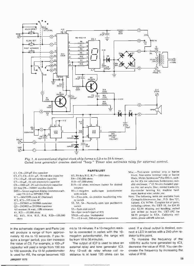
RESET
HOLD/RESET ESL
S. SIA TIME INTERVAL
RELAY
SLOW SET
-S3 FAST ADVANCE - _L-
S4
R5 IM
DURATION
GND
SIB
RI
20
O 25
2
24
22
+12
SI 191
ICI 5309
R6-RI2 =IK
6 NMNv 10
7 R7 9
8 R8 8 NJ/JJJ- 9 R9
VAMN
4127
- R4 330K
01
DIS I
10 RIO 4 `MMN II RII 2 ,...
NNWN..-- 12 R12 3
`MMNv--
26
8 4
-+I2
C2 -L
6,7
+ 2
02 2N3903
RI7 IK
IC2 3 RI8 555 47K
DI IN4001=
O
103 555
R14 IOOK
13
+ C7 IOyF
D2 C6
TOI IN4001X yF
2
R19 (SELECT
FOR VOLUME)
TI
12 VAC FROM TI
EXT SPKR
Fig. 1. A conventional digital clock chip forms a 0.5-s to 24-h timer. Gated tone generator creates desired "beep." Timer also activates relay for external control.
CI . C4-220-pF disc capacitor C2. C3, C6 -0.01-µF, 16 -volt disc capacitor C5 -10-µF, 10 -volt tantalum capacitor C7-I0-µF, 16 -volt electrolytic capacitor C8 -1000-µF, 25 -volt electrolytic capacitor DI thru D9 -1N4001 rectifier diode DIS 1-Seven-segment display (common -cath-
ode) TIL3 (3 or HP5082-7740 IC 1-MM5309 clock IC (National) IC2, IC3-555 timer IC QI-2N3905 or 2N3906 transistor Q2 -2N3903 or 2N3904 transistor All resistors 1/4 watt, 10% tolerance: RI,R21-10,000 ohms R2, R13, R 14, R 15, R 16, R20-100,000
ohms
PARTS LIST
R3, R6 thru R12, R 17-1000 ohms R4-330,000 ohms R 18-47,000 ohms R19-10 ohms minimum (select for desired
volume) RS-I-megohm audio -taper potentiometer
with switch SI-Two-pole, six -position nonshorting rota-
ry switch S2. S3, S4-Normally-open spst pushbutton
switch S5-Spdt slide switch $6-Spst switch (part of R5) SPKR-45-ohm loudspeaker TI-I2.6-volt, 500-mA power transformer
Misc.-Two-screw terminal strip or barrier block; four -screw terminal strip or barrier block; Molex Soldercons!' (for DISI); sock- ets for ICs (or substitute Soldercons); suit- able enclosure; I" (2.54 -cm) threaded spac-
ers (4); red acrylic filter; control knobs (2); dry -transfer lettering kit; machine hard- ware; hookup wire; solder; etc.
Note: The following items are available from Caringella Electronics, Inc., P.O. Box 727, Upland, CA 91786: Complete kit of parts.
including cabinet, No. UET-I K, for $34.95 plus $2.00 shipping and handling; etched
and drilled pc board No. UET-IPC for
$6.95 postpaid in USA. California resi-
dents, please add 6% sales tax.
in the schematic diagram and Parts List will produce a range of from approxi- mately 10 ms to 10 seconds. If you re- quire a longer period, you can increase the value of C5. For example, a 100-µF capacitor will yield a range from 100 ms to 100 seconds. If a 10-M potentiometer is used for R5, the range becomes 100
ms to 18 minutes. If a 10-megohm resis- tor is connected in series with the 10-
megohm potentiometer, the range will
be from 18 to 36 minutes. The output of IC2 is used to drive an
external relay and tone generator 1C3.
Any 12 -volt dc relay whose coil re-
sistance is at least 120 ohms can be
used. If a visual output is desired, con- nect a LED in series with a 240 -ohm re-
sistor to this point. To increase the frequency of the
1000 -Hz audio tone generated by IC3,
decrease the value of R18. You can de- crease the frequency by increasing the value of R18.
JANUARY 1979 59
AmericanRadioHistory.Com

60
y
.
b
A.
,-,Ra F- --(RI
_ ̂ o
01 B
C --107 lE- -1D6
D. DISI =R7 -4D8 IF -4D9 If1-
E -{IO2 1- Caf' -R8 - R9 -(1219 )- RIO G
-11D1 C6
R11
H - R12 IC3 °
c2 1 1
T-IR/7 }-
- - -
-
K
M
N
P
R
1 s
Ñ
T _ u
02 -{R13 -C3
vJ'
Fig. 2. Actual -size etching and drilling guide for printed circuit board is shown at top. Component placement diagram is directly above.
(17
5 - 6iy a.,
- -- -411r._-_-*..tes:_,>
sir---,.sir---,., I
{ - :
:9 o- -as -i 1 L'¢ . °
gn 44 i 9I } l R7 l
1 r n cr¢. zm - , ..
- V L, 9
,,, .\
._
f
Fig. 3. Photo shows interior construction details of author's prototype.
Construction. The timer circuit is best assembled on a printed -circuit board. The actual -size etching -and -drilling guide and separate components -place- ment diagram for the pc board are shown in Fig. 2.
Before you proceed to wire the pc board, place it foil side up on a hard, flat surface. Slip a strip of five Molex Solder - cons® onto the pins on each side of DIS1. (Do not remove the connecting strips of metal on the Soldercons until di- rected to do so.) Lower the display onto the pc board, guiding the pins of the Sol- dercons into the appropriate holes on the board. Because of the hard surface under the board, the pins will not go in as far as they might otherwise. Do not try to push them in all the way. Simply solder them to their respective traces on the board, using only as much heat and solder as necessary to assure a good electrical and mechanical connection in each case. Leave the display in place and cover its top surface with a piece of masking tape.
CURRENT LIMITING
RESISTOR RESET
4N28 OR
SIMILAR
INPUT
GND
Fig. 4. An optoisolator can be used to interconnect two timers for extremely long timing durations.
Flip over the pc board and install the resistors, capacitors, diodes, and tran- sistors. Refer to the components -placer ment diagram in Fig. 2 for proper com- ponent location and orientation. Install sockets in the locations for the integrat- ed circuits. Then install 1C2 and IC3 in their sockets. Do not install ICI until last and, when you do so, be sure to practice safe handling procedures for MOS de- vices. (This clóck chip is a PMOS device that can be damaged by static fields if it
is not handled properly.) Flip over the board assembly and carefully flex the connecting strips on the display's Sol- dercons until they break away. Three or four flexes will generally do the trick. Temporarily set the board assembly aside.
Next, referring to Fig. 3 and the lead
POPULAR ELECTRONICS
AmericanRadioHistory.Com

X and K Band photo, machine the top half of the enclo- sure in which the project is to be housed. (If you plan to build the power supply into the project, select a large enough enclosure to accommodate it without in-
terference to the other elements in the circuit.) Drill the holes for the various switches, control, and circuit board standoffs; cut a window for the display; and make a pair of slots (or drill Ef"
holes) for the screw -type terminal strips or barrier blocks. Use a dry -transfer let- tering kit to label the various switches, control, and terminal strip points, as shown in the lead photo. Then mount each item, except the circuit board as- sembly, in its respective location.
Solder an 8" (20.3 -cm) length of hook- up wire to pads A through U on the cir- cuit board assembly. Flip over the board and peel away the tape from the display. Then mount the circuit board assembly, with DIS1 centered in the window in the top half of the box, with threaded spac- ers and machine hardware. If you wish to protect the display and enhance its contrast for easier reading, cement a
piece of red acrylic plastic over the win- dow on the inside of the box before mounting the circuit board assembly on its spacers.
Drill a series of I/4" holes in the bottom half of the enclosure to perforate it for the loudspeaker. Then mount the speak- er, with a protective screen between it
and the enclosure wall. Refer back to Fig. 1 and interconnect the circuit board assembly with the control, switches, ter- minal strips, and speaker, using the wires connected to holes A through U on the board. Trim the wires as necessary as you connect them. Finally, arrange the wires neatly and lace them together and assemble the case.
Using the Timer. RESET pushbutton switch S2 or the RESET input on the four - lug terminal strip returns the interval tim- er and display to zero. The display re- mains at zero as long as the RESET
switch is closed or the RESET input is
grounded. Releasing either initiates the timing cycle. If you desire remote opera- tion of the reset feature, you can use the optoisolator circuit shown in Fig. 4.
The SLOW SET and FAST SET pushbut- tons are used to preset the interval tim- er. The SLOW SET button is not opera- tional in the two shortest interval posi- tions of S1 (1 second and 10 seconds).
The divide -by -two switch (S5 in Fig. 1
but not labelled in Fig. 3) effectively cuts all of the timing intervals that are select- ed by S1 in half. O
2 -Band Radar Detector Extra Long Range gffective on all Stationary
and Moving Scans Sight and Sound Dual Alert System:
Extra Loud Buzzer Alarm and Signal Light
Test Position: Adjusts Sensitivity for City and Highway
On/Off Switch: Makes Operation Easy
Until now, you would have paid 580, 5100, and more for some o the important features that are built into our exceptionally sensitive adar receiver. Thanks to miniature, solid state technology, it is the most ad- vanced X and K band system available...at an incredibly low price. We have tested many of the more expensive bands on the market today. Some were large and bulky, some were of su:h short range that by the time they picked up radar there was no time to react. Others tad no ON/OFF switch. Maybe that's a small thirg, but plugging aid un- plugging those u t its eventually loosened solde- joints. YOU DRIVE SAFER, MORE CONFIDENT The unit has a ccnvenient ON/OFF switch. It a so has a Test Position that let's you know the unit is operational. Reduces false alarms. And enables you to adjust sensitivity for city and highway driving. Dual Alert System picks up oth X and K band radar. You hear its Extra Loud Buzzer and see its Signal Lamp when radar is being used. Long Range Sersitivity gives you ample time to react, before enterinz a sudden reducec speed zone. Without question, the system is the most full -featured most reliable and best value radar detector we have ever tested! -
EASYTOINSTALL ILi5, Unit plugs into auto or truck lighter. For
18 -wheelers, it has an easy reverse to positive ground. It also features Visor Clip and Dash:'. Mount installation.
CREDIT CARD ORDERS Illinois:312-595-0461 CALL TOLL FREE 800-323-2272Telet Orders: 25-5268
ontem CIRCLE NO
For Autos and Trucks Long Range Sensitivity Alerts You In Time To Read Increases Your Driving Awareness Encourages Safer, More Alert Read Skills Guaranteed
64488 DRIVE WITH IT FOR 10 DAYS
AT OUR EXPENSE If you are not entirely satisfied with your unit, after 10 days, return it for a prompt refund. The unit is backed by the manufacturer's 90 day parts and labor guarantee.
:1 Please send me _Radar Detectors H $44.80 ea. (Item 00681. Add $2.50 per detector for shipping and handling.
Illinois Residents add 5% sales tax. I Check or M.O. Enclosed
O Please Charge My Credit Card:
IO AmericanExpress O Mastercharge O Carte
O Bank Amer./Visa O Diners Club Blanche
Credit Card No
Mastercharge Bank No. Lap Date
f' Name
IAddress
City
State Zip
ISignature
PE/IC-00l
790 Maple Lane Bensenville, II. 60106 orar ©CM1 1978162R
marketing Inc. 13 ON FREE INFORMATION CARD
1 tin el kEltWWIMItTUX 1015 »NI V nor 1aWl
All bury,retK wc e,.oie --
428977 A
- . ;
C}-iji0$á Q
You can build a better organ than you can buy!
C 284842 wA$H Moron
A magnificent Schober Electronic Organ What a marvelous way to put your special
talents to work! With our Schober Electronic Organ Kits and your skill, you can build your- self some very special satisfaction,. and a life- time of great music!
Schober Organs are literally far superior to comparably -priced "ready-made" units. You could actually pay twice as much and get no better organ...and miss the fun of assembling it yourself. A PC board at a time, component by component, you'll assemble your own "king of instruments" And when you're done, you'll wish there was more to do. And there is! For then, Schober will help you learn to play, even if you've never played a note before!
Schober Organ Kits range from $650 to $2850, and you can purchase in sections to spread costs out...or have two-year time pay- ments. Combine the incomparable quality of Schober components with your talent...and produce a far better organ than you can buy!
Thousands of others have, ever since 1955. You can have all the details, without cost
or obligation. Just send the coupon for the fascinating Schober color catalog (or enclose $1 for a record that lets you hear as well as see Schober quality.) Why not clip it right now, before you forget?
The CitO/Q7 Organ Corp., Dept. PE -81 43 West 61st Street, New York, N.Y. 10023
O Please send me Schober Organ Catalog.
O Enclosed please find $1.00 for 12 -inch L P.
record of Schober Organ music.
NAME
ADDRESS
CITY STATE ZIP
CIRCLE NO. 47 ON FREE INFORMATION CARD
JANUARY 1979 61
AmericanRadioHistory.Com

THE AUTOMOTIVE industry has tak- en advantage of the latest tech-
niques in modern electronics technolo- gy. As a result, many of the components in late -model automobiles have become more difficult to diagnose when trouble occurs. An example of this is in the auto- motive battery and charging system, where the old-style battery, dc genera- tor, and electro -mechanical voltage reg- ulator have given way to the sealed bat- tery, alternator, and solid-state voltage regulator. These new components are superior to the ones they replaced, but they also require more sophisticated test procedures to analyze and isolate faults.
It seems only natural that electronics technology should provide the means to check these components. The automo- tive battery and charging system moni- tor described in this article, provides such a check. It can be constructed at low cost, yet gives the accuracy and de- pendability suitable for a professional as well as an amateur. The monitor uses four LED's to provide an indication if a fault arises and also indicates possible sources of trouble. This feature will elim- inate unnecessary replacement of prop- erly operating components.
Circuit Operation. The analysis of an automotive battery and charging sys- tem can be acc m ished by-monit6ng the battery voltag under several op re a- tional conditions, hen comparing the measured value to knov tandard.
,,..-611111bú.
',LOW BATT
NO CHARGE
CI WOE STATOR
*OVER CHARGE
BY TONY CARISTI
Electronic diagnostic instrument for locating
and identifying
problems in
battery or
charging
systems
f
41~No I 1n ides a.. t'
C.
q li
4 41) . )!.,' 4,_.s.____,,,,,
%
-- Ir
a b
R
. - -i IMI11-
A
AmericanRadioHistory.Com

CI
JrOy
DI IN2069
+5.75V
R6 10 01<
RI
R2 IK
R4 IK
PARTS LIST CI ,C2 - 10-11F, 15 -volt electrolytic DI - I N2069 or similar D2 - I N4148 or similar
R7,R9,R 15,R I9 - 10,000 -ohm, 10% resistor R8,R 12,R 16,R20 - 1000 -ohm, 10% resistor R 10 - 59(X) -ohm, I% resistor
+8V
ICI - µA 78GU adjustable regulator (Fair- child)
R 13 - 25,500 -ohm, 1 % resistor R 17 - 19,6(0-ohm,1 % resistor
IC2 - LM339 quad comparator LEDI through LED4 - Red LED R I ,R2,R4 - 1000 -ohm, 1% resistor
Misc. - Suitable enclosure, interconnecting leads, optional spst switch, mounting hard- ware. etc ADJ
R3 - 1000 -ohm potentiometer, pc mount R5 - 39,200 -ohm, 1% resistor
Note: The following are available from: A.Ca- risti, 69 White Pond Rd., Waldwick, NJ
C2 R6,R 1 I ,R 14,R 18 - 100,000 -ohm, I% resis- 07463: etched and drilled pc board at $2.50; I0yF tor a set of I I precision resistors at $2.50.
IC2=LM339
T +12V
R15 10K
14
t LED 2 NOT CHARGING
R16 IK
D2 1N4148
R17 19.6 K
10
+6.7 V
1KR18 100
RI9 I0K
LED 3 DEFECTIVE DIODE OR STATOR
Fig. 1. Comparator monitors voltage difference between reference 8V line and battery input. One LED glows to indicate possible fault.
A properly operating battery and charging system will have a battery ter- minal voltage of about 12.6 volts when the engine has been turned off for some time, and between 13.5 and 15.0 volts when the engine is running and the bat- tery is being charged.
If the battery voltage is below 11.5 volts with the engine not running, the battery is either in a very low state of charge or has a damaged cell. If the bat- tery voltage is less than 12.7 volts with the engine running, the charging system is inoperative. If the voltage is less than 13.4 volts, then there is insufficient charging; if there is more than 15.1 volts across the battery terminals, overcharg- ing is occuring.
The circuit shown in Fig. 1 constantly monitors the battery voltage, while LED displays indicate any improper electrical condition. The basic reference voltage for the monitor is formed by IC1 which is an adjustable voltage regulator that is set to a precise 8 -volt output.
This voltage reference is fed to four precision voltage -divider networks (R5/ R6, R10/R11, R13/R14 and R17/R18) that provide levels of 5.75, 7.55, 6.35 and 6.7 volts respectively), to individual sections of IC2. By feeding half the bat- tery voltage to the noninverting input, the corresponding voltages then be- come 11.5, 15.1, 12.7 and 13.4 volts.
In IC2A, C and D, the precision refer- ence voltage is fed to the inverting input (-) of the comparator, while half the sys- tem's battery voltage (via divider R1, R2) is coupled to the noninverting (+) in-
put. As long as the voltage at the non - inverting input is greater than the volt- age applied to the inverting input, the output of the comparator is high. The as- sociated LED is thus extinguished, in-
dicating that the system is normal for that particular voltage level.
Should the battery voltage drop below the reference level, the comparator out- put drops to zero, causing the associat- ed LED to indicate a malfunction.
Note that IC2B has its input terminals reversed; that is, the reference voltage is applied to the noninverting input while the battery voltage is applied to the in- verting input. This causes its associated LED to glow if the battery voltage ex- ceeds the reference level. This condition is also caused by a fault in the charging system. Diode D2 is connected between the output of IC2C and the inverting in- put of IC2D to prevent LED3 from light- ing if LED2 is glowing. This not only pre- vents the two indicators from lighting at the same time, but also provides a pos- itive indication of a particular type of fault in the charging system.
Diode 01 is connected in series with the positive input lead to protect the cir-
cuit against damage caused by an acci- dental reversal of the input leads.
Construction. The circuit can be as- sembled on a small pc board such as that shown in Fig. 2. Observe the polari- ties of the two diodes and two polarized capacitors. A 14 -pin socket can be used for IC2. Pin 1 of IC2 can be identified by a small dot or mark on the plastic case.
The four LEDs can be mounted where they are easily observed, and then con- nected to their respective pads on the pc board. Each LED must be clearly identi- fied as to indicated fault.
A long length of insulated wire can be connected between the monitor positive input and the battery positive terminal The monitor's negative input may be connected to a chassis ground.
Test and adjustment. A 0- to 16 - volt do power supply and an accurate dc voltmeter are used to test the monitor.
Observing the correct polarity, con- nect the two monitor input leads to the power supply, and set the power supply for a 12 -volt output.
Connect the voltmeter positive lead to ICI pin 3, and the negative lead to ground. Adjust R3 until the voltmeter in- dicates precisely 8 volts.
Connect the voltmeter across the
JANUARY 1979 63
AmericanRadioHistory.Com
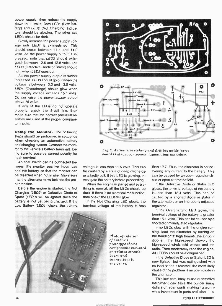
power supply, then reduce the supply down to 11 volts. Both LED1 (Low Bat- tery) and LED2 (Not Charging) indica- tors should be glowing. The other two LED's should be dark.
Slowly increase the power supply volt- age until LED1 is extinguished. This should occur between 11.4 and 11.6 volts. As the power supply output is in- creased, note that LED2 should extin- guish between 12.6 and 12.8 volts, and LED3 (Defective Diode or Stator) should light when LED2 goes out.
As the power supply output is further increased, LED3 should go out when the voltage is between 13.3 and 13.5 volts. LED4 (Overcharge) should glow when the supply voltage exceeds 15.1 volts. Do not raise the power supply output above 16 volts!
If any of the LEDs do not operate properly, check the 8 -volt line, then make sure that the correct precision re- sistors are used at the proper compara- tor inputs.
Using the Monitor. The following steps should be performed in sequence when checking an automotive battery and charging system. Connect the moni- tor to the vehicle's battery terminals, be- ing sure to observe correct polarity for each terminal.
An spst switch can be connected be- tween the monitor positive input lead and the battery So that the monitor can be disabled when not in use. Make sure that the alternator drive belt has the pro- per tension.
Before the engine is started, the Not Charging (LED2) or Defective Diode or Stator (LED3) will be lighted since the battery is not yet being charged. If the Low Battery (LED1) glows, the battery
.1 r
O "10
.. O
8V. o
1 «lo .1 i
are° Tie R 5 - s-
' I Ilk --R9- RI =-R7- 1` { o I -R6--
-R8 -
IC2
.**N ~di -
R12-,!
R13 - .-..- R16
411-R14 ---' \ --R 20 --+ All G IL, r -RIB-- rRl9--+ RI7- f-R15-It -D2-4/ --,impim,"_ ÷i- , --
Fig. 2. Actual size etching and drilling guide for pc board is at top; component layout diagram below.
voltage is less than 11.5 volts. This can be caused by a state of deep discharge or a faulty cell. If this LED is glowing, in- vestigate the battery before proceeding.
When the engine is started and every- thing is normal, all the LEDs should be dark. If there is an electrical malfunction, then one of the LEDs will glow.
If the Not Charging LED glows, the terminal voltage of the battery is less
Photo of interior of author's prototype shows components mounted on printed circuit board and connections to enclosure.
than 12.7. Thus, the alternator is not de- livering any current to the battery. This can be caused by an open regulator cir- cuit or open alternator field.
If the Defective Diode or Stator LED glows, the terminal voltage of the battery is less than 13.4 volts. This can be caused by a shorted diode or stator in the alternator, or an improperly adjusted regulator.
If the Overcharging LED glows, the terminal voltage of the battery is greater than 15.1 volts. This can be caused by a shorted or misadjusted regulator.
If no LEDs glow with the engine run- ning, load the alternator by turning on the headlights' high beams, the air con- ditioner, the high-speed blower, the high-speed windshield wipers and the radio. Then moderately race the engine. All LEDSs should be extinguished.
If the Defective Diode or Stator LED is now lighted, but was extinguished with no load on the alternator, the most likely cause of the problem is an open diode in
the alternator. This low-cost, easy -to -use automotive
instrument can save the builder many dollars of repair costs, making it a worth- while investment in parts and labor. O
64 POPULAR ELECTRONICS
AmericanRadioHistory.Com

BY BUD WEISBERG, K2YOF
REMOTE BUID c
NU'
Low-cost, reliable switch permits selecting
from among six antennas
==reefing multiple antenna systems of- fers the communications buff in-
creased operating flexibility and fre- quency coverage. Unfortunately, it can
also add appreciably to station cost and complexity-especially when the anten-
nas require separate feedlines. Present- ed here is an alternative to a large in- vestment in coaxial cable-a low-cost, remotely controlled coaxial switch.
The Remote Antenna Selector Switch enables the user to quickly select one of
R
six antennas. Equally important, it pro- vides a silent, reliable indication of the selection without any need for relay - holding current or the imposition of dc or a -f control signals on the feedline. The project can be assembled from inexpen-
POWER SUPPLY/INDICATOR UNIT
R8 san
117 V AC
FI 3A
Fig. 1. Schematic diagram of the Remote Aotennu Selector Switch.
PARTS LIST
CI -10(Ní -µF. 50 -volt computer grade elec- trolytic
C2 -0.01-µF ceramic disc DI -1 N4(0)3 rectifier FI -3 -ampere fast -blow fuse I I -110 -volt neon pilot light assembly JI through J7-SO-239 coaxial connector K I -12 -position rotary stepping solenoid with
24 -to -28 -volt de coil (Ledex Series 5 or equivalent)
Ml - 0-to-ImA meter movement The following are 1 -watt. 5% tolerance car-
bon composition fixed resistors: R I -78.0(X) ohms R2-33.00() ohms R3-23,(00 ohms R4 -17,0(x) ohms R5-13,000 ohms
MI 0-ImA
Pi REMOTE SWITCFI UNIT
INDICATOR LINE
RI 78K
CONTROL LINE
C2 \ R9 .019F 100n
COAXIAL TRANSMISSION LINE
R6-10.500 ohms R7 -2500 -ohm wirewound potentiometer R8 -68 -ohm. I -watt, 10% tolerance fixed car-
bon composition resistor R9 -100 -ohm, 1/2 -watt, 10% tolerance fixed
carbon composition resistor RECTI-1(x)-PIV. 4 -ampere modular bridge
rectifier .
SI-S-ampere spst switch S2 -5 -ampere, normally -open, momentary
contact pushbutton switch S3 -11 -posit ion, I -pole ceramic rotary switch
(Centralab No. 2503 or equivalent) S4-1 I -position, I -pole phenolic switch wafer
(Centralab No. JD or wafer from No. 1403 switch)
TI -24 -to -28 -volt ac, 2 -ampere transformer (Radio Shack No. 273-1512 or equivalent)
KI
R6 10.5K
DI
r
R2 33K
R3 23K
R4 I 7 R5 13K
INDICATOR WAFER
JI FEED- LINE
L R -F WAFER
J2 ANT. I
J3 ANT. 2
J4 ANT. 3
J5 ANT. 4
AJ6 NT. 5
J7 ANT 6
Misc.-Suitable enclosures, 4" x 4" x 2"
(10.2 x 10.2 x 5.1 cm) aluminum utility box. coaxial cable and PL -259 connectors, %" (6.4 -mm) flexible shaft coupling, 2- or
3 -conductor cable, machine and self -tap- ping hardware, silicone cement, PVC tape, No. 14 copper wire, solder, etc.
Note-Suitable surplus stepping solenoids are
available from several sources, including Poly Paks, Box 942, South Lynnfield, MA 01940 (Cat. No. 92CU3493) and Fair Radio Sales, 1016 East Eureka, Lima, OH 45802 (Cat. No. MX 167869G I ).
JANUARY 1979 65
AmericanRadioHistory.Com

NSIENN'
N s \
Fig.'?. Photo of llrerem.ole unit rrrl ootenIio select ion hut irotor.
sive surplus and junk -box parts and gives a level of performance rivalling that of commercial products costing much more.
About the Circuit. A schematic dia- gram of the Remote Antenna Selector Switch appears in Fig. 1. Upon the ap- plication of line power, electrolytic capa- citor Cl draws charge from stepdown transformer T1 through bridge rectifier RECT1 and resistor R1. When momen- tary pushbutton S2 is depressed, Cl discharges via the coil of K1, a 12 -posi- tion rotary stepping solenoid. Eleven - position rotary switches S3 and S4 are driven by the shaft of K1, so the switches advance one position when the solenoid is energized.
In this project, only alternate switch contacts are employed. The solenoid must therefore be stepped twice to advance the switches to the next posi- tion. Wafer S3 performs the antenna switching function. The other wafer, S4, is part of the indicator circuit, as are fix- ed resistors R1 through R6, potentiome- ter R7, and milliammeter M1. As K1 ro- tates the switch shafts, the effective se- ries resistance between the negative side of M1 and ground varies. This causes the meter movement to deflect and indicate the antenna selection on a
modified meter scale. If the solenoid is
stepped only once, the meter will read OFF, indicating that S2 must be closed once more to advance the mechanism to the next antenna position.
__ . * T r. °.. ..
.
Construction. The Remote Antenna Selector Switch comprises two units, the switch proper, shown in Fig. 2, and the power supply which appears in Fig. 3.
Also shown in Fig. 2 is the position in- dicating meter, which can be built into an enclosure with the power supply or mounted on a separate panel.
Fig. 3. Piloto o(the power rUpg)lft tie -it,.
The power supply is relatively simple and is most easily constructed using point-to-point wiring techniques. A barri- er terminal strip such as that mounted on the prototype power supply's chassis will facilitate interconnections with the power line, switches and solenoid. Due to the amount of charge it must hold, ca- pacitor C1 must be a high-grade compo- nent such as a computer -grade elec- trolytic. Similarly, the pushbutton switch employed as S2 must be able to handle the substantial current flowing when Cl discharges through K1.
The meter scale will have to be rela- belled. The zero line should be labelled the OFF position, the full-scale mark la- belled position 6, and the remaining five numerals spaced equally between these two extremes. A more or less sensitive meter movement can be used, but in the former case larger values will be re- quired for R1 through R6 and in the lat- ter case smaller values. Non-standard resistor values can be obtained by com- bining standard ones in series qr parallel.
The remote unit shown in Fig. 2 con- sists of a solenoid driving two rotary switches. In the author's prototype, the solenoid is a Ledex Series 5 type with a
1-nk-inch (4.8 -cm) diameter case. It is
available from most industrial suppliers. Surplus solenoids can be obtained from several sources, two of which are given
66 POPULAR ELECTRONICS
AmericanRadioHistory.Com
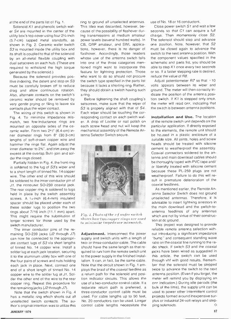
at the end of the parts list of Fig. 1.
Solenoid K1 and phenolic switch waf- er S4 are mounted in the center of the
utility box's top cover using four 21/ -inch (5.7 -cm) tapped metal standoffs, as
shown in Fig. 2. Ceramic wafer switch S3 is mounted inside the utility box and its shaft is coupled to that of the solenoid by an all -metal flexible coupling with dual setscrews on each hub. (These are required to withstand the high torque generated by the solenoid.)
Because the solenoid provides pos- itive indexing, the detent and stop on S3 must be carefully broken off to reduce drag and allow continuous rotation. Also, alternate contacts on the switch's ceramic wafer should be removed by very gentle prying or filing to leave six contacts plus the wiper contact.
The wiring of this switch is shown in
Fig. 4. To minimize impedance mis- match, two low -inductance rings are mounted on opposite sides of the ce- ramic wafer. Form two 2/2' (6.4 -cm) in- ner diameter rings from 8" (30.3 -cm) lengths of soft -drawn copper wire and hammer the rings flat. Again adjust the inner diameter to 21/2", and trim away the excess at the overlap. Butt -join and sol- der the rings closed.
Partially hidden in Fig. 4, the front ring is soldered to the lug of S3's wiper and to a short length of tinned No. 14 copper wire. The other end of this wire should he soldered to the inner conductor pin of J1, the FEEDLINE SO -239 coaxial jack. The rear copper ring is soldered to lugs held in place by the switch assembly screws. A I í -inch (6.4 -mm) insulated spacer should he placed under each of these solder lugs to position the two rings about 7/16 inch (11.1 mm) apart. This might require the substitution of
longer screws for those used by the switch manufacturer.
The inner conductor pins of the re- maining SO -239 jacks (J2 through J7) can now he connected to the appropri- ate contact lugs of S3 via short lengths of tinned No. 14 copper wire. Install a
solder lug at each jack location, securing it to the aluminum utility box with one of the four pairs of screws and nuts holding each jack in place. Next, connect one end of a short length of tinned No. 14
copper wire to the solder lug at J1. Sol- der the other end of the wire to the rear copper ring. Repeat this procedure for the remaining jacks (J2 through J7).
Note that the switch shown in Fig. 4
has a metallic ring which shorts out all
unselected switch contacts. The au- thor's original intention was to utilize this
ring to ground all unselected antennas. This idea was discarded. however, be- cause of the possibility of flashover dur- ing transmissions at medium amateur power levels (several hundred watts). In
CB, QRP amateur, and SWL applica- tions, however, there is no danger of flashover. Accordingly, those readers whose use of the antenna switch falls into one of the three categories men- tioned might want to incorporate this feature for lightning protection. Those who want to do so should not procure the switch type specified in the parts list
because it lacks a shorting ring. Rather, they should obtain a switch having such a ring.
Before tightening the shaft coupling's setscrews, make sure that the wiper of S3 is properly aligned with that of S4. Each wiper should be touching the cor- responding contact on each switch waf- er. A drop of Loctite or nail polish on each screw head and nut will keep the mechanical assembly of the Remote An- tenna Selector Switch secure.
Fig. 4. Photo of the r-fwofer switch shows how two copper riPUS ore II m,(1 to minimize iinpedn ilce mismatch.
Adjustment. Interconnect the power supply and switch units with a length of two- or three -conductor cable. The cable should have the same length as that re-
quired to run from the remote switch unit to the power supply in the finished instal- lation. It can, in fact, be the same cable. Note that the circuit shown in Fig. 1 em- ploys the braid of the coaxial feedline as
a return path for the solenoid and posi- tion indicator circuits. This allows the use of a two -conductor control cable. If a
separate return path is preferred, a
three -conductor control cable must be
used. For cable lengths up to 50 feet, No. 20 conductors can be used. Longer control cable lengths necessitate the
use of No. 18 or 16 conductors. Close power switch Si and wait a few
seconds so that Cl can acquire a full
charge. Then momentarily close S2.
The solenoid should step and advance one position. Note, however, that S2 must be closed again to advance the switch to the next antenna position. With the component values specified in the
schematic and parts list, you should be able to step K1 once every two seconds or so. If a faster stepping rate is desired, reduce the value of R8.
Adjust potentiometer R7 so that +-10
volts appears between its wiper and ground. The meter will then correctly in-
dicate the position of the antenna.posi- lion switch. If K1 is stepped only once, the meter will read OFF, indicating that the switch is between antenna positions.
Installation and Use. The location of the remote switch unit depends on the particular application. If directly exposed to the elements, the remote unit should he housed in a plastic enclosure of a
suitable size. All joints, holes and screw heads should be treated with silicone cement to weatherproof the assembly. Coaxial connectors soldered to the an-
tenna and main downlead cables should be thoroughly taped with PVC tape and/ or liberally treated with silicone cement because these PL -259 plugs are not
weatherproof. Failure to do this will re-
sult in premature deterioration of the coaxial feedlines.
As mentioned earlier, the Remote An-
tenna Selector Switch does not ground unselected antennas. Therefore, it is
advisable to insert lightning arrestors in
the main downlead and the switch -to -
antenna feedlines of any antennas which are not by virtue of their construc- tion at dc ground.
This project was designed to provide reliable remote antenna selection with- out introducing a significant impedance 'bump" and consequent standing wave ratio on the coaxial line running to the ra-
dio shack. If switch S3 and the coaxial jacks have been wired as suggested in
this article, the switch can be used through vhf with good results. Remem- ber that the solenoid must be stepped twice to advance the switch to the next antenna position. (Even if you forget, the meter will remind you by displaying an oFF indication.) During idle periods (the bulk of the time). the supply unit can be used to power other intermittent control projects formed around inexpensive sur- plus or industrial 24 -volt relays and step- ping solenoids. O
JANUARY 1979 67
AmericanRadioHistory.Com

Microcomputer ROM Board Buying Directory Make & Model Price '
(S)
Power required
(mA)2 -
PROM
cap.
PROM
type ,
Can Firmware
1 Program Remarks
+8V +16V -16V '
FOR 5.100 BUS:
Advanced Computer
Prods.
A-8KK 24 (b) X X X 8K 2708 no Power -on jump; reset jump; user breadboard
60 (k) area.
90 )w)
Byte
4K PROM 100 X X 4K 1702A Powers only ROM being accessed.
PROM Boot 120 X X 8K 2708 Auto -start option; 2704 option.
CG RS Microtech
16K ROM 60 (k) 16K 2708 no opt. Tiny BASIC, various operating systems dissassem-
100(w) bier/trace/editor firmware optional.
Computerware, Inc.
EPROM Board 125 (w) 16K 2708 no no
32K 2716
Cromemco
Bytesaver 145 1k) 500 8K 2708 yes programmer
245 (w) 16PR 145 (k) 400 800 500 16K 2708 no Bank select; "address anticipation." 32KBS 195 1k) 2.1A 32K 2716 yes RAM can overlay ROM address space; bank select;
" 295 (wl DMA compatible.
D.C. Hayes
80.708 163 (w) 8K 2708 no
Ibex
16KPB 85 (k) 16K 2708 no Blocks can be disabled to save power and allow 110 (w) RAM to overlay address space.
IMSAI
PROM 4-512 165 (k) 4K 1702A Includes 512 -byte EPROM. 247.(w)
PROM 4-4 399 (k) 4K 1702A Includes 4K EPROMs.
579(w)
Ithaca Audio
EP16K 25 (b) 320 750 500 16K 2708 no no Enables ROMs individually, allowing overlay by 32K 2716 RAM.
EPPR06 85 3' yes yes 'One 2708, one 2716, one 2732; up to 4 wait
states if desired.
Jade Computer
MR8 100 (k) lA 8K 2708 no 890 Can alternate RAM and ROM; external RAM
121 (w) mon. disable.
MR16T 100(k) lA 16< 2716 no S90 As above.
121 (w) mon.
JG RNR 105 (k) to 4 to no no 'Can use 1702, 2704, 2708. 2716, 5204, 6834.
168 (w) 32K' JG 8/16 30 (b) lA 8 or 2708, no no Unused locations free for RAM.
60(k) 16K 2716
PROM SETTER 210 1k) lA 0 yes no 'Programmer only for 1702, 2704, 2708, 2716,
375 (w) 5204, 6834, With software listing.
Mountain Hardware
ProROM 164 (k) 500 7.5K AMI- yes monitor Can program 1 byte at a time; includes 512
214 (w) 6834 bytes RAM.
Objective Design
Databank 200 (k) 16K 2716/ yes yes
2708
Piiceon
PS -K -OK 167 1k) X X X 8K 2708 yes mon. Reset -jump capability.
PS -W -OK 220 (w) X X X 8K 2708 yes mon. Same, wired.
PS -W -4K 257 (w) X X X 8K 2708 yes mon. Same, w. 4 EPROMs.
PS -W -8K 296 (w) X X X 8K 2708 yes mon. Same, w. 8 EPROMs.
Processor Tech.
GPM 149 (k) 8K 2708 no 2K CUTER 1K RAM; ALS-8 firmware optional.
189 (w)
68 POPULAR ELECTRONICS
AmericanRadioHistory.Com

Make & Model
GPM -SOL
2KRO
Price'
IS)
99 (k) 123(w)
65(k)
+8V
600
Power required
(mA)2 +16V -16V
350
PROM
cap.
10K
2K
PROM i r Can Firmware
type : Program
2708 no none
1702
Remarks
Same, less RAM and firmware.
Solid State Music
MB -3 65 (k) 250 40 4K 1702 no Switch -selectable address and wait (0.4) cycles.
MB -8A 95 (k) 160 10 10 16K 2708 no Similar, but 0-8 wait states, power -on vector
jump, allows disabling any 1K block for RAM
address overlay.
MB -9 80 (k) X 4K no Can intermix RAM or PROM in 256 -byte increments;
jump on reset or power -up.
Szerlip
R -N R 117 (k) 64K any no For any 24 -pin PROM; also has 1K RAM,
168 (wl 24 -pin parallel I/O.
PROM Setter 210 1k) 700 200 200 64K same yes yes Similar, but can program.
375 (w)
Teletek
System Central
Interface
385 (w) X X X 3-12 27' yes 2K mon. "For 27t]8, 2716, 2732; has 256 bytes RAM, I/O,
reset -jump.
Vector Graphics
PR1 129 (w) 2K 1702A no S75" 'Includes 1K RAM; 1K monitor ex tra; jump -on -
reset; MWRITE.
PR2 175 (w) 12K 2708 no S75' As above, but addressable in two 8K blocks; 3K
unused space allows RAM overlay.
Wameco
EPM-I 30 (b) 4K 1702 no no Phantom disable.
200 (k)
230 1w)
EPM-2 30 (b) no no Phantom disable & bank sel.
455 1w) 16K 2708 no no 2708 version.
1225 (w) 32K 2716 no no 2716 version.
Western Data
Systems
PRO/EX 1 296 (k) 2A 125 125 BK 2716 no yes' 'MICROBUG OS; also contains Video RAM, on-
board r -f modulator.
Xyhek Prammer I 259 (w) 2K 1702 yes opt.` *1.8K EPROM, 256 bytes RAM; programming firmware
$32, external program socket $17.
Prammer III 370 (w) 31K 2708 yes opt.' 'Similar, but firmware$32, zero -insertion -
T2716 force ext. socket $19; 1K RAM, 30K PROM.
PD458
Make & Model Price' Power required PROM PROM' Can Firmware Remarks
(5) (mA)2 cap. type Program
+8V +12V -12V
FOR SS 50 BUS:
Gimix
8KP 90 (w( X 8K 2708 no
4KPPD 198 1w) Y 4K 2708 yes yes PROMS can be inserted & removed from program-
ming sockets with power on; can program 4
at once.
Midwest Sci.
EPR-8 95 (k)' X X 8K 2708 'Sockets, $15 extra.
159 )w)' PRR.68 95 (k)° 4K' 1702A 'Sockets, S25 extra. 4K includes 256 bytes RAM,
150 (w)'
SOS Technical
MCM6830 145 (k) 800 2K 2716 8K yes
Smoke Signal
P38 129 )w) 8K 2708 no optional Interfaces to POP -I EPROM programmer, Oliver
P38-1 129 (w) 8K 2708 yes optional paper tape reader.
Notes:
' Ibl=bare board, Ikl=kit, Iwl=wued. Prices usually do not include PROMs.
=1n ampbres where indicated by "A." Power consumption may vary
with number of PROMs.
'See "Remarks" column
JANUARY 1979 69
AmericanRadioHistory.Com
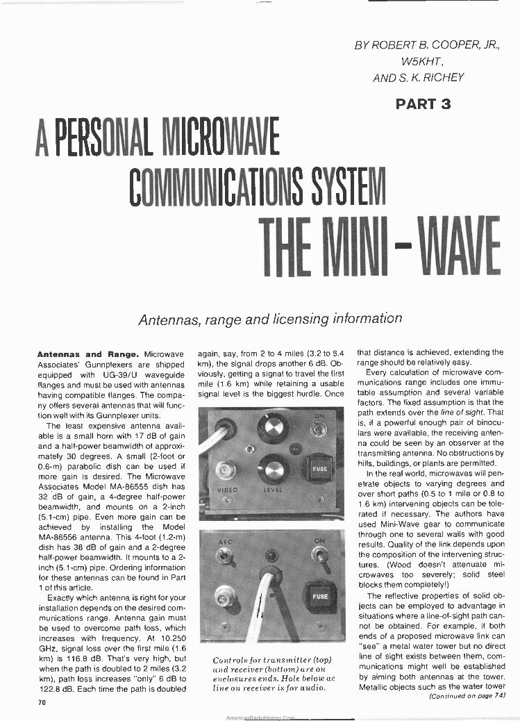
BY ROBERT B. COOPER, JR.,
W5KHT,
AND S. K. RICHEY
PART 3
PERSONAL MICROJAVE
CO11MUNICATIONS SYSTEÍ.1
Antennas, range and licensing information
Antennas and Range. Microwave Associates' Gunnplexers are shipped equipped with UG-39/U waveguide flanges and must be used with antennas having compatible flanges. The compa- ny offers several antennas that will func- tion well with its Gunnplexer units.
The least expensive antenna avail- able is a small horn with 17 dB of gain and a half -power beamwidth of approxi- mately 30 degrees. A small (2 -foot or 0.6-m) parabolic dish can be used if
more gain is desired. The Microwave Associates Model MA -86555 dish has 32 dB of gain, a 4 -degree half -power beamwidth, and mounts on a 2 -inch (5.1 -cm) pipe. Even more gain can be achieved by installing the Model MA -86556 antenna. This 4 -foot (1.2-m) dish has 38 dB of gain and a 2 -degree half -power beamwidth. It mounts to a 2 -
inch (5.1 -cm) pipe. Ordering information for these antennas can be found in Part 1 of this article.
Exactly which antenna is right for your installation depends on the desired com- munications range. Antenna gain must be used to overcome path loss, which increases with frequency. At 10.250 GHz, signal loss over the first mile (1.6 km) is 116.8 dB. That's very high, but when the path is doubled to 2 miles (3.2 km), path loss increases "only" 6 dB to
122.8 dB. Each time the path is doubled
again, say, from 2 to 4 miles (3.2 to 5.4 km), the signal drops another 6 dB. Ob-
viously, getting a signal to travel the first mile (1.6 km) while retaining a usable signal level is the biggest hurdle. Once
VIDEO LEVEL
4 =r
MC
FUSS,J
ON
r
FUS
r
Controls for transmitter (top) and receiver (bottom) are on enclosures ends. Hole below ac line on receiver is for audio.
-4
that distance is achieved, extending the range should be relatively easy.
Every calculation of microwave com- munications range includes one immu- table assumption and several variable factors. The fixed assumption is that the path extends over the line of sight. That is, if a powerful enough pair of binocu- lars were available, the receiving anten- na could be seen by an observer at the transmitting antenna. No obstructions by hills, buildings, or plants are permitted.
In the real world, microwaves will pen- etrate objects to varying degrees and over short paths (0.5 to 1 mile or 0.8 to
1.6 km) intervening objects can be tole- rated if necessary. The authors have used Mini -Wave gear to communicate through one to several walls with good results. Quality of the link depends upon the composition of the intervening struc- tures. (Wood doesn't attenuate mi-
crowaves too severely; solid steel blocks them completely!)
The reflective properties of solid ob- jects can be employed to advantage in
situations where a line -of -sight path can- not be obtained. For example, if both ends of a proposed microwave link can "see" a metal water tower but no direct line of sight exists between them, com- munications might well be established by aiming both antennas at the tower. Metallic objects such as the water tower
(Continued on page 74) 70
AmericanRadioHistory.Com

n'
It's all in this latest
and it's
T r.Ys t ,.-.r_ALOG,P.?0? , - , .
----- --- i
i'^. '
ti.:. .n '
.HEAmKIT MAIL ORDER CATALOG 84 .ran..e...a...I win euw.e. _°"+1.:,: _
Have you seen a real computerized, digital home weather station...
- or a precisíor+ electronic scale for you( bathroom. .. or advanced educational programs that let you learn electronács or automotive maintenance at home...or a to- tally. broadbanded amateur radio transceiver ...or the word's only programmable calcr TV with fully automatic antenna rotor? If you haven't, send for a free Heathkit Catalog.
You'll see nearly 400 unique electronic prod- ucts - the latest technology, the newest; fea- tures, the .best values. The kinds of quality products Heath Comparry has been offering for some 60 years! It's fassi,natingreading. But the excitement doesn't stop there.
.s. _i. gLgºzo_ I r=
Send for your FREE Catalog Today! Heathkit products are displayed, sold and serviced coast -to -coast at Heathkit Electronic Centers, -(units of Schlumberger Products -Corporation). See 'the CL -678
white pages of your phone book. . 111. MI I.1. IN
w..,,,,., ... .. ro. <...,
These sophisticated products are easy to build kits. Illustrated step-
by-step instructions guide you and detailed explanations help you
learn how the product works from the inside out. It's fun,.easy and
educatiónal.
Só send for your free catalog today. It's the best way we know to find out what's' new in
electron ids and have fun doing it!
1
ti
HEATH I Heath Company, Dept. 010-492 Schlumberger " Benton Harbor, Michigan 49022
Please send me my FREE Heathkit Catalog. I am not currently receiving catalogs.
Name
Address
City State
Zip
JANUARY 1979 CIRCLE NO. S ON FREE INFORMATION CARD
73
AmericanRadioHistory.Com

(Continued from page 70) in this hypothetical situation usually re-
flect microwave energy very efficiently. In some instances, a large building or mountain will reflect enough signal to make communications possible.
Other factors that govern range are transmitter output power, the method of modulation employed, receiver sensitiv- ity and noise figure, path loss, the re-
quired signal-to-noise ratio, etc. In FM
systems such as the Mini -Wave com- munications link, range is affected by
the "FM improvement factor," which is
the advantage gained by more fully modulating the carrier (increasing the frequency deviation and modulation in-
dex), the "FM threshold," the point at
which limiting improves intelligibility, the design and operating characteristics of
the limiter and discriminator, and other factors too complex for adequate treat- ment here.
The curves in Fig. 11 show the line -of - sight ranges for Mini -Wave transmitters and receivers employing 17 -dB horns
(A), 32 -dB parabolic dishes (B), and 38 -
dB dishes (C), plotted against signal-to- noise ratio. Intermediate ranges will re-
sult if different antennas are used at the transmitter and receiver. If the goal of flawless video reception is established, an S/N ratio of 48 dB is required.
These range plots show what a pow- erful tool antenna gain is! In the Mini -
Wave system, transmitter output power is fixed at a nominal value of 20 mil-
liwatts. Receiver noise figure, dis-
criminator and limiter characteristics and
the transmitter modulation index are es-
tablished by circuit design and compo- nent parameters. Accordingly, increas- ing antenna gain is the simplest and
most effective way to increase range.
The dramatic increase in signal-to- noise ratio that can be obtained by re- placing the stock 17 -dB horns supplied by Microwave Associates in its
MA -87141-1 package is illustrated by both Fig. 11 and the following example. Assume that 17 -dB horn antennas are used at each end of a 2.5 -mile (4.0 -km) path and that the baseband signal at the receiver's video outpu'. has an (unac- ceptable) signal-to-noise ratio of 20 dB. If one of the horns is replaced with a 2 -
foot (0.6-m) parabolic dish, system gain increases 15 dB. Thus, the video signal- to-noise ratio becomes 35 dB.
The quality of the received picture can
be further improved by replacing the oth- er horn antenna with a 2 -foot (0.6-m) dish. Adding the second dish increases the signal-to-noise ratio at the receiver output by an additional 15 dB to an ex-
cellent 50 dB, 2 dB above the require- ment for flawless video reception. Em-
ploying 4 -foot (1.2-m) dishes at both ends of a Mini -Wave System makes possible excellent video reception over 13 -mile (20.8 -km) paths, very good pic- ture quality at 32 miles (51.2 km), and
usable video reception over distances greater than 64 miles (102.4 km)- assuming that the terrain permits such long line -of -sight paths!
A final word about the range plots shown in Fig. 11. They were derived without any allowance for a fade margin. Commercial microwave links are de- signed to provide more signal at the re- ceiving antenna than is necessary for proper reception. This extra margin of
signal strength is included in the link to
compensate for equipment aging, in-
creases in path loss which can occur during heavy rain, etc. Typical commer- cial systems made by Bell Telephone and others provide the receiver with 40 dB more signal than is needed under op- timum conditions.
Such a margin adds considerably to the cost of a communications system. Commercial users are willing to pay the price for high reliability. Otherwise, their ability to forward information (and to col- lect revenue for the service) would be
dependent on the exact amount of atmo- spheric attenuation at any given instant, as well as other factors beyond their control.
Those employing Mini -Wave equip- ment can usually tolerate brief signal outages during extremely heavy rain- storms. They therefore do not have to in-
vest the large sums required for sub- stantial fade margins. However, if a par- ticular Mini -Wave application calls for a
fade margin, it can be obtained simply
.I
Range of several miles can be
obtained with 2'parabolic dish.
by installing an antenna with more gain than is needed for clear reception. For example, if a horn providing satisfactory results is replaced with a 4 -foot (1.2-m) dish, a fade margin of 21 dB or more will
be obtained-at a cost of $265.
Setup. Place the transmitter and re-
ceiver relatively close together, say, 50 to 100 yards (47.7 to 95.4 m) apart. Con- nect a video source to the transmitter in- put jack and a video monitor to the re- ceiver's output jack. If the audio circuits have been built, connect a high -imped- ance signal source to the transmitter's audio input jack and a pair of head- phones or an external audio amplifier to the demodulator's output jack. Optically align the antennas and apply power to both units.
If the Gunnplexers have been ordered for compatible transmit and receive fre- quencies and the Varactor bias levels have been set at +4 volts, contact should be established almost instan- taneously. Next, place receiver switch S1 in the AFC ON position if you have not already done so, and adjust the trans- mitter's video level control (R30) for op- timum picture quality if it was not set ear- lier with the aid of an oscilloscope. Simi- larly, audio level control R7 should be adjusted for best -sounding audio if it
was not previously adjusted for the pro- per ±25 -kHz subcarrier deviation.
After you have gained some experi- ence operating the Mini -Wave system over short distances, you can begin to
extend the signal path. If horn antennas are employed, aiming them becomes relatively noncritical as the path length increases because the antennas have -3 -dB beamwidths of approximately 30
degrees. Parabolic dishes, however, are extremely directional and demand very precise positioning-a change in anten- na alignment of only a few degrees will mean the difference between no signal at all and perfect video reception!
The following procedure is recom- mended for the installation of parabolic dish antennas. If possible, establish communications over the path with horn
7 antennas. Picture quality need not be
good, but the presence of a video signal (even one that is just detectable) will simplify matters greatly. Next, replace the horn on the receiving Gunnplexer with a 2 -foot (0.6-m) or larger parabolic dish antenna. Leave the transmitting horn fixed and adjust the position of the receiving dish for optimum reception. Then, if necessary, replace the transmit- ting horn with a parabolic antenna and
74 POPULAR ELECTRONICS
AmericanRadioHistory.Com

A Band Plan for the10.0-to-10.5-GHz Amateur Allocation
This plan has been developed so that the 10-GHz amateur band can accommo- date the largest possible number of simul- taneous, interference -free video (or video plus audio subcarrier) transmissions in a
given area. Placing the receiver's Gunn lo-
cal oscillator 45 MHz above the transmitter frequency and taking advantage of anten- na polarization (horizontal or vertical) char- acteristics results in 33 one-way channels. For two-way communications, receiver
Channel group
1
2
3
4
5
6
7
8
9
and transmitter are reversed, generating 33 reply channels.
The "national calling frequency" for gen-
eral use is channel B4, 10.2 GHz transmit
and 10.245 GHz receive. Note that chan- nel C5's transmit frequency coincides with
the receive frequency of the national call-
ing channel. This has been done deliber-
ately to allow frequency netting and cali-
bration of equipment against a local CW
(A ) beacon operating on channel C5.
A B C D
(horizontal) (horizontal) (vertical) (vertical)
T R T R T R
10.010 10.055 10.035 10.080 10.025 10.070
10.065 10.110 10.090 10.135 10.080 10.125
10.120 10.165 10.145 10.190 10.135 10.180 10.175 10.220 10.200 10.245 10.190 10.235 10.230 10.275 10.255 10.300 10.245 10.290
10.285 10.330 10.310 10.355 10.300 10.345
10.340 10.395 10.365 10.410 10.355 10.400
10.395 10.440 10.420 10.465 10.410 10.455
10.450 10.495
'Antenna polarization is given in parentheses.
T R
10.050 10.095 10.105 10.150 10.160 10.205 10.215 10.260 10.270 10.315 10.325 10.370 10.380 10.425 10.435 10.490
aim it for best picture quality on the re- ceiving monitor. A radio or land -line voice link will make this task easier.
Never move or attempt to align both antennas simultaneously! Always leave the transmitting antenna undisturbed (pointed in the direction you believe it
should be) when aligning the receiving antenna. Conversely, when adjusting the transmitting antenna leave the re- ceiving horn or dish fixed in position. Both the extreme directionality of para- bolic dishes and the relatively abrupt quieting characteristics of the FM i -f
make antenna alignment very critical, but the increase in range and improve- ment in picture quality make the task well worth the effort.
Licensing Your Gunnplexer Sys- tem. If you are a Technician or higher class radio amateur, your ticket author- izes you to operate Gunnplexers on the 10.0-to-10.5-GHz amateur band. The author has drawn up a band plan for the 10.0-to-10.5-GHz allocation so that as many amateurs as possible can place Mini -Wave systems on this 500 -MHz - wide band. (See box above for informa- tion on band plan.)
Readers who are not licensed ama- teurs can either obtain a ham ticket or apply to the FCC for authorization to op- erate Gunnplexers on nearby frequency allocations.
Satisfying the requirements for a
Technician Class amateur license is rel-
atively easy. Moreover, Technicians have extensive operating privileges on vhf, uhf, and other microwave bands, and can access repeaters and orbital satellites carrying transponders.
Two microwave allocations are avail- able to persons not holding valid ama- teur radio licenses. The 10.5-to-10.55- GHz allocation is a "developmental" band for which the Commission grants "Experimental" licenses. Just above
50
40
30
ó z Z N
20
o
this, from 10.55 to 10.68 GHz, is a "mo- bile" band for which "Research" li-
censes are granted. At last check, less than 50 Research licenses had been granted in the United States for opera- tions on the mobile band. Gunnplexers for these bands are available on special - order from Microwave Associates.
The Research license is intended pri- marily for persons developing communi- cations "projects," while the Experimen- tal license is granted to facilitate the de- velopment of new equipment which might ultimately be placed on the com- munications market. If you are interest- ed in simply placing the Mini -Wave sys- tem as described in this article on the air for microwave experimentation, the Ex-
perimental license is appropriate. Those wishing to expand on this concept and create new microwave communications systems are suitable candidates for a
Research license. Both licenses are granted and licensees' operations regu- lated pursuant to Part 5 of the FCC's Rules and Regulations, which governs Experimental Radio Services (Other Than Broadcast).
To obtain either license, write to the nearest field office at the FCC, request- ing Form 442. Upon receipt of this form, fill it out and return it to the Commis- sion's office in Washington, D.C. The form requires that you submit details of
the system you propose to construct, its
intended application, and how and where you will use it. Both licenses have terms of one year and are renewable.
Safety and RFI Considerations. The negative effects of microwave ra-
diation upon living tissue are well docu- PICTURE QUALITY
EXCELLENT
9 NOTE:OBJECTIVE S GNAL TO NOISE RATIO FOR FLAWLESS VIDEO IS 48 dB
O
M a m
RANGE IN MILES
m N A 0 0 m N tn
Fick. 11. Range plot for horn (A), 2 -foot parabolic (B) and 4 -foot para bolic (C) dish antennas when used with the Mini -Wave microwave communications system.
VERY GOOD
USABLE
JANUARY 1979 75
AmericanRadioHistory.Com
trigger
past
soldering
action
WITH
Weller® COMFORT -GRIP GUNS
Dual-áction trigger permits instant choice of 2 heats in all Weller's pro- fessional quality guns, the most com- fortable, best -balanced units .. .
anywhere. Pre -focused light for hard - to -see work areas like TV or under -dash auto service. Premium copper tips get up to temp faster ... pre -tinned for instant soldering. Cutting or smoothing tips also, UL -listed and factory pre- tested. Models for any + service including solid- state. Guns alone or kits with case, spare tips, and accessories.
Ask your local
distributor or write...
J COOPER
TheCooperGroup Electronics Division
WELLERR WI55' XCELITE PO BOX 728. APEX. NORTH CAROLINA 27502. 919/362.7511
76 CIRCLE NO. 53 ON FREE INFORMATION CARD
mented, with the eyes being especially vulnerable. Exactly what level of intensi- ty is hazardous to human beings has been and continues to be the subject of a worldwide debate. The Federal gov- ernment's Occupational Safety and Health Administration (OSHA) has set a safety limit of 1 milliwatt per square cen- timeter (1 mW/cm2).
Microwave Associates Gunnplexers are low -power devices, having a nomi- nal power output of 20 mW. However, the microwave radiation is concentrated in a relatively small area. The power density at the open (antenna) end of the waveguide is approximately 6.2 mW/cm 2, considerably greater than OSHA's maximum permissible value. Fortunate- ly, r -f power density decreases dramati- cally with distance, and the intensity of microwave radiation is at safe levels 6
inches (15.2 cm) from the mouth of the waveguide.
To adhere to the most conservative radiation exposure limits, no one should place himself directly in front of the horn (or parabolic dish) antenna for a dis- tance of several feet. Never look into the open end of a Gunnplexer while it is os- cillating or place any portion of your body inside the waveguide, horn, or dish antenna. If you follow these simple rules, you can operate your Mini -Wave system in complete safety.
The 10.0-to-10.5-GHz amateur band and the 10.55-to-10.68-GHz "mobile" band are on either side of the 10.525- GHz frequency commonly used by "X - band" police radar. This frequency is ac- tually inside the 10.5-to-10.55-GHz "de- velopmental" band. During hundreds of hours of operating car Mini -Wave sys- tem, the authors have never suffered in- terference from the low -power police ra- dar transmitters.
On several occasions, however, our 10.25-GHz transmitters have driven po- lice radar receivers and motorists' X - band radar detectors "absolutely nuts." We therefore offer these words of ad- vice-operating a Gunnplexer near X - band police radar units is unwise. The police radar receiver will experience in- terference at a far greater distance (sev- eral miles) than that at which a motor- ist's radar detector will be triggered by the police radar transmitter.
In Conclusion. We have presented here the first low-cost, compact mi- crowave audio/video communications link project. The world of microwaves is waiting for you, and the Mini -Wave sys- tem will enable you to explore it. O
YOU'RE
READING
POPULAR
FiECTRONICS. That already says a lot about
you. That you're fascinated by the diversity of electronics.
Everything from microcomputers to audio,
from construction projects to ham radio. Who knows what area of electronics will catch
your interest next? That's why you read P.E. To keep in
touch with all that's new and best in the many worlds of
consumer electronics.
Popular Electronics World's largest -selling electronics magazine
POPULAR ELECTRONICS
AmericanRadioHistory.Com

4111IF1/
aRL
Solid State THOSE VERSATILE MULTIS
GENERALLY, the simpler a semiconductor device, the
greater its versatility-that is, the more circuits in which it
can be used. Transistors and diodes, for instance, are the
most versatile of all devices, and are used in virtually all types
of circuits. As increasingly complex devices such as ICs are
considered, however, versatility drops and some LSI devices,
a calculator IC, for example, may be so specialized as to have
a relatively small number of potential applications. But there
are exceptions: the multifunction ICs, devices designed speci-
fically for maximum versatility. TI's SN76477 complex sound
generator, is one example. The ubiquitous 555 timer is anoth-
er and there are more, including Intersil's (10900 N. Tantau
Ave., Cupertino, CA 95014) powerful 8038 waveform genera-
tor and National Semiconductor's (2900 Semiconductor
CURRENT ¡1 SOURCE y71
CURRENT SOURCE
a2
11
21
COMPARATOR
COMPARATOR #2
FLIPF LOP
BUFFER
A nn 9
SINE WAVE ADJUST
SINE WAVE OUT
TRIANGLE OUT
DUTY CYCLE
FREQUENCY ADJUST
.+VCC
FM BIAS
BUFFER
6
O Ncc
O V or GND
B
SINE CONVERTER
NC
NC
SINE WAVE ADJUST
GNDC
TIMING CAPACITOR
SOUARE WAVE OUT
FM SWEEP INPUT
Fig. 1. Intersil's 8038 waveform generator: (A) functional block diagram; (B) pin connections.
By Lou Garner
Drive, Santa Clara, CA 95051) intriguing LH0094 multifunc- tion converter.
Functionally, the 8038 comprises two externally adjustable constant -current sources, a pair of comparators, a flip-flop, buffer amplifiers, and a sine converter, as shown in Fig. 1A. A
monolithic IC assembled in a standard 14 -pin DIP, the device is capable of producing sine, square, triangular, sawtooth and pulse waveforms over a frequency range from less than 0.001 Hz to more than 1.0 MHz. The output frequency is indepen- dent of the supply voltage and generally depends only on the values chosen for the external resistive and capacitive timing components. If desired, however, the 8038's output can be
either frequency modulated or swept over a wide range simply by applying a control voltage to its appropriate terminals (Fig 1B). Quite stable, the unit has a maximum rated frequency drift of only 50 ppm/°C. Its other features include low distor- tion (typically, 1.0% or less), good linearity (0.1% or better), a
variable duty cycle from 2% to 98%, and the capability of driv-
ing TTL devices. Adaptable to a variety of power supplies, the 8038 may be operated on either single -ended or dual dc pow- er sources from 10 to 30 V or from ±5 to ±15 V, at less than 20 mA.
In operation, the IC's nominal output frequency depends upon the values of the two external current -source (or timing) resistors connecting pins 4 and 5 to +Vcc as well as upon the value of the timing capacitor between pin 10 and -Vcc (or cir- cuit ground). The symmetry of the waveforms varies with the duty cycle and this depends upon the relative values of the
two timing resistors. Three different configurations for the tim- ing resistors are given in Fig. 2. Of these, the arrangement shown in Fig. 2A is the most versatile, permitting the greatest degree of operator control over both the frequency and wave- form symmetry through the two timing potentiometers (RA and RB). A 50% duty cycle, delivering symmetrical wave- forms, is achieved when RA equals RB.
Requiring a single potentiometer, the arrangement shown in Fig. 2B permits a relatively small variation of the duty cycle on either side of the 50% point and may be preferred for some applications. In the last circuit, Fig. 2C, the timing resistor pins are shorted together and a single potentiometer is used for control. While this arrangement does not permit an indepen- dent adjustment of duty cycle, it is the simplest and least ex- pensive of the three designs.
Typical variations in cutput waveform symmetry with square -wave duty cycles of 50% and 80% are shown in Figs. 3A and 3B, respectively. With a 50% duty cycle, the outputs are a triangular wave, sine wave and square wave. As the duty cycle is increased or decreased, the triangular wave changes into a sawtooth and the square wave into a rectangu- lar wave, approaching a narrow pulse as the duty cycle is in-
creased or decreased to near its extreme limits. The sine wave becomes highly distorted, for the wave -shaping circuit
JANUARY 1979 77
AmericanRadioHistory.Com

VGG
Fig. 2. Timing resistor connections for the 8038 as explained in text.
used on the chip is designed to modify a triangular wave into a
sine form and requires a symmetrical input for proper shaping action.
While the output signal waveform symmetry with respect to
time depends on the ratio of the two timing resistors (RA and RB), the symmetry with respect to ground depends on the type of power source used. If a single -ended power supply is used, the average levels of the triangular and sine - wave outputs will be one-half the supply voltage, with the square wave alternating between +Vcc and ground. The square -wave output is not committed, however, and requires an external load resistor. If desired, this resistor may be re- turned to a different dc source. In computer or control applica- tions, for example, the square -wave output load could be re- turned to a +5-V dc source even though the 8038 is operated on a 15-V dc supply. Here, the output level would be compat- ible with TTL devices, permitting the square wave to be used as a clock signal for logic circuits. On the other hand, if a dual or split power supply is used, all signal waveforms will vary symmetrically on either side of circuit ground (or 0 V).
The 8038 can be used as a basic signal or clock source in
timers, signal generators, alarm systems, audio sweepers, computer circuits, control networks, musical instruments, tone generators, and special-purpose test instruments. Two units may be cascaded, with one serving as a sweep signal source for the second, or the IC may be used in combination with oth- er special-purpose devices, such as TI's SN76477 complex sound generator. A small sampling of the scores of possible application circuits for the 8038 is given in Figure 4. Abstract' ed from Intersil's 8 -page data brochure for the device, these
/*NN/N
A
VGG
V o GND
'VGG
circuits feature standard components and may be duplicated quite easily in the home laboratory or workshop for experi- mental tests or incorporation into more complex equipment designs. Neither layout nor lead dress is critical but good wir- ing practice should be followed.
Referring, first, to Fig. 4A, the 8038 is controlled by a FET switch to form a simple tone -burst generator. Timing capacitor C is effectively shorted to ground by the 2N4392 FET as long as the FET's gate is held positive or near ground potential, thus preventing oscillation. The circuit is strobed on by apply- ing a negative pulse to the FET's gate through a 1 N914 isola- tion diode. A second diode, connected to output terminal 9,
ensures oscillator start-up on the same slope each time it is
switched on. The second circuit, Fig. 4B, is a wide -range audio oscillator
covering from 20 Hz to 20 kHz without band switching. This 1000:1 range is achieved by applying a variable dc control voltage to the IC's FM sweep input terminal (8) while holding the voltage across timing resistors RA and RB at a relatively low level. A 1 N457 series diode drops Vcc and the voltage ap- plied to the timing resistors through the Duty Cycle (or symmetry) potentiometer to several millivolts below the max- imum voltage available from the 10,000 -ohm frequency con- trol. A large trimmer (15 megohms) connected to pin 5 helps minimize duty -cycle variations with frequency, while a 100- kilohm potentiometer connected to pin 12 as a distortion con- trol serves to optimize the sine -output waveform.
In contrast to Intersil's 8038, which is essentially a signal source, National Semiconductor's LH0094 multifunction con- verter is a versatile signal processor. With analog inputs, the
B
5
Fig. 3. Typical waveforms with (A) 50% and (B) 80% duty cycles.
78 POPULAR ELECTRONICS
AmericanRadioHistory.Com

Fig. 4. Typical 8038 circuits; (A) tone -burst generator; (B) audio oscillator.
device can be used for precision multiplication and division, for squaring and extracting square roots, for generating trig- nometric functions, as an exponentiator, and as a logarithmic amplifier. Depending on the auxiliary circuits used, the IC can be employed in compressors, expanders, analog computers, alarm systems, sensor translators, controls, measuring instru- ments, and test equipment.
Functionally, the LH0094 comprises circuits for determining the logarithmic ratio of two input voltages, multiplying this by a
known constant (m), summing the result with the logarithmic equivalent of a third input voltage, and determining the antilog of the final value, as shown in Fig. 5A. In a broad sense, the device is the electrical equivalent of a sliderule. Assembled in
a 16 -pin metal DIP, the LH0094 includes two uncommitted precision resistors, RA and RB, which may be used for setting the multiplying factor (m) to either 0.5 or 2.0 (Fig. 5B). Offering typical input impedances of 100,000 ohms, the IC will accept input levels up to 10.0 volts, and can be operated from dual dc sources from ±5.0 to ±22.0 volts. Its output impedance is
approximately 1 ohm and, with an average output load of 10,000 ohms, it can supply an output signal swing of 12.0 volts max. when operated on a standard ±15 V dc supply. In
ac applications, the device offers a 3 -dB bandwidth of 10 kHz. Typical application circuits for the LH0094, abstracted from
National Semiconductor's 10 -page data brochure for the de- vice, are illustrated in Fig. 6. Precision multiplier and divider circuits are shown in Figs. 6A and 6B, respectively. In both de- signs, optional clamp diode D1 should be included for those applications in which the inputs may be either "open" or sub- ject to negative voltages.
Referring, first, to Fig. 6A, this circuit develops an output voltage, E0, equal to the product of input voltages Vy and Vz divided by 10, and offers a typical accuracy of 0.02% when
Vy
A
LOG
RATIO
LOG
A3 - V Vg V.
LOG -1
Al- ONO
TOP VIEW
VA V,
Fig. 5. National's LH0094 multifunction converter: (A) functional block diagram; (B) pin connections.
properly adjusted. Here, a precise 10 -volt reference level is
applied to the Vx terminal (pin 13). Prior to use, an accurate 10 -volt level is applied to the Vy and Vz terminals and trimmer R2 is adjusted until the output is precisely 10.000 V.
In the divider circuit, Fig. 6B, output voltage E0 is equal to
10 times the result of input voltage Vz divided by input Vx. Again, a precise 10 -volt reference level is required, but ap- plied, in this case, to the Vy terminal (pin 2) through trimmer R2 and to the A3- terminal (pin 16) through R1. With a typical accuracy of 0.05%, the divider requires multiple adjustments
10V REF
(LH0070 OR
L H0075)
vy
A
m 1
Eo' 10 V' 0-- Vx R2
10V REF 10k
(LH0070 OR
IB LH0075)
1
D1
1N914
v -
R3
v-
RI 2M
10k
131 $ 1N914
V=
V.
115
Vx
14 13
R4
10M
12 16 10 I9 -0
Al-
E.
V+ Vx Al- GND
L H0094
Vy V
Vz
RA R6
2 14 ¿5
V-
6 7 i
Fig. 6. Precision multiplier (A) and (B) divider circuit.
JANUARY 1979 79
AmericanRadioHistory.Com

Fig. 7. Reader's rilcllit for a television commercial killer uses the ubiquitolts 555 timer integrated circuit.
+I 2VOCC1-
C3. 0.I yF
.-, C4 yF
O
RI IM
TIME
+
CI
33yF
NC IN4001 = 4 8
TP 01
2N2222 OR EOUIV
r C2
OIyF
555
I
ro
3
R2 e.2 K
prior to use. First, with the 10-V reference applied to Vv, 0.1
volt is applied to Vx and VZ and R3 is adjusted until Eo is ex-
actly 10.000 V. Second, 10 volts is applied to all inputs and R2 is adjusted until Ep is 10.000 V. The entire procedure is then repeated at least once.
Reader's Circuit. Guy Isabel (1725 Henri-Bourassa East
Blvd., Apt. 25, Montreal, Quebec, H2C 1J5, Can.) has sent us
another of his simple, but interesting, circuits. Guy writes that
each time one of his circuits is featured, he receives a flood of
correspondence from other experimenters and hobbyists, and
that this has resulted in his establishing a number of "pen
pals" with whom to exchange ideas and circuits. Dubbed a TV
l I I CI Addon MiniDisc for theTRS80*
O .,
80
I' Trademark of Tandy Corporation
1'
Dual and triple drives also available.
'tjlevtltlltfllltnsilli
\-N't{S
only
$39900 Requires 16K RAM,
Level II BASIC and Expansion Interface.
CIRCLE NO
from
PERCOM PERCOM DATA COMPANY, INC.
Dept.PE 318 BARNES GARLAND, TEXAS 75042 Phone: (214) 272-3421
To Order Ca111-800-527-1592 41 ON FREE INFORMATION CARD
AUDIO SOURCE
KI
TV SPKR
Commercial Killer, Guy's latest circuit, shown in Fig. 7, is
another application for the 555 IC. Easily duplicated in a sin-
gle evening, Guy's design is essentially a simple touch -plate
controlled time -delay relay. When connected to a TV set, the
control permits the viewer to shut off the sound for adjustable
periods up to more than thirty seconds simply by lightly touch-
ing a small control plate. At the end of the preset period,
sound is restored automatically. Referring to the schematic diagram, the 555 is wired as a
monostable multivibrator. In operation, the circuit's timing cy-
cle is initiated by a random voltage pulse applied to pin 2
when the control plate (TP) is touched by the operator's fin-
ger. Afterwards, the circuit is insensitive to further control
pulses until its operating cycle is completed. The duration of
the timing cycle is directly proportional to the time required to
charge Cl through R1 and hence is dependent on RI's ad-
justment. With the component values specified in the dia-
gram, the maximum period is somewhat over a half minute.
During the timing cycle, pin 3 is high, supplying a base bias to
npn transistor 01 through series current limiting resistor R2,
and causing the transistor to conduct, closing relay Kl. A dpdt
type, K1 switches the TV set's audio output terminals, from
the loudspeaker voice -coil leads to an 8.2 -ohm load resistor
(R3), thus silencing the set. At the end of the timed period, pin
3 goes low, K1 drops out, and the TV set's loudspeaker is re-
connected, restoring normal operation. Guy has used standard, readily available components in his
circuit design. Transistor Q1 is type 2N2222, although other
general-purpose npn transistors should work as well. A con-
ventional 1-megohm potentiometer is used for R1, R2 is a
half -watt resistor, and R3 a 2 -watt unit. Capacitors Cl and C4
are 16 -volt electrolytics, while C2 and C3 may be low -voltage
ceramics, paper tubulars, or plastic film types. Relay K1 is a
dpdt type with a 12-V 50-mA dc coil (Radio Shack #275-206
Calectro D1-974, or equivalent). Finally, the touch plate (TP)
is simply a small metal plate of a few square inches.
Neither layout nor lead dress is critical and the project can
be assembled using the builder's choice of wiring techniques.
All dc polarities must be observed, of course, and care must
be taken not to overheat the semiconductor devices when sol-
dering. The final installation is quite simple. With the TV set's power
off, the loudspeaker leads are disconnected and these,
together with the audio output leads, are connected to appro-
priate terminals on K1. Next, time delay trimmer R1 is adjust-
ed for an optimum interval long enough to cover most TV
commercial messages. Guy set his unit for 28 seconds. O
POPULAR ELECTRONICS
AmericanRadioHistory.Com

;T: Experimenter's Corner
ANALOG COMPUTER CIRCUITS,
IF YOU'RE like most readers of this column, you prefer to have us de-
scribe digital circuits. Considering how the microprocessor revolution is making a major impact in virtually every area of electronics, that's to be expected. All the excitement about digital technology, however, has left a less glamorous but very valuable technology virtually ig- nored by experimenters and engineers alike. The technology to which I refer is
analog computation. If you think analog computers are a
relic of the past, think again. Recent developments have made possible so- phisticated analog computer ICs with unprecedented accuracy. One of these new circuits, billed as the first single - chip analog computer is the Analog De- vices AD534 precision multiplier -divider. Available for about the same price as many microprocessors, the AD534 can perform all the MDSSR functions (multi- plication, division, squaring and square rooting) with ease and in real time. There are no elaborate software require- ments and the AD534 will perform any of these operations while the input infor- mation is changing at up to 1 MHz.
At the conclusion of the second in- stallment of this two-part series on anal- og computer circuits, we'll take a closer look at the AD534 and see how it's used to perform each of the MDSSR func- tions. Meanwhile, we're going to cover the basics of analog computing by ex- perimenting with a potpourri of home- brew analog computer circuits.
Fig. 1. Analog adder made from potentiometers,
JANUARY 1979
By Forrest M. Mims
PART 1
After you've read this and next month's columns I think you'll agree that analog computer circuits can perform many tasks much more efficiently and for less money than microprocessors. Let's begin with a little background infor- mation that will help you better under- stand some of the key differences be- tween analog and digital circuits.
Fig. 2. Simple multiplier made from potentiometers.
Analog vs Digital. Most readers of this column already know the essential difference between analog and digital in-
tegrated circuits. Analog ICs, such as amplifiers, oscillators and timers, pro- cess or produce signals whose ampli- tudes are continuously variable over a
given range. Digital ICs, on the other hand, process or produce signals which occupy either a low or high state.
An amazing number of applications use either digital or analog circuits. Late- ly, of course, the trend has been toward digital almost exclusively. In some ways, however, this trend (or is it a fad?) is
clearly unfortunate. Consider the digital voltmeter (DVM). The unprecedented accuracy of a three- or four -digit DVM is
ideal for making measurements of fixed voltages. But have you ever tried to monitor a slowly changing voltage with a
DVM? If not, good luck! The stream of constantly changing numbers is almost impossible to read and makes little sense. An old-fashioned panel meter with an analog readout (pointer and scale) offers a much better solution to
this common problem.
When it comes to computers, digital technology has the advantage in ac-
curacy, programmability and computing power. Analog computers, however, are ideal for simulating a real -world system such as a structure, machine, dam, air- craft or missile. Simply rotating a few
control knobs enables the computer's operator to observe the effect of changes ón the system as they take place (in real time). Contrast this simple procedure with the elaborate software manipulation required to vary conditions in a digital computer's program.
Analog computers have one further advantage you should know about: low
cost. You can build an analog computer capable of solving a general quadratic equation (ax2 + bx + c = 0) with a doz- en or so inexpensive op amps, a few dozen resistors and potentiometers and
a digital voltmeter. And you can rewire (reprogram) this computer so that ít can solve many other mathematical func- tions and equations also.
Adding with Resistors. A simple analog adding calculator can be made from a pair of linear potentiometers equipped with pointer knobs and scales and an ohmmeter. For best results, compromise with digital technology and use a digital multimeter. The circuit for the adder is shown in Fig. 1.
The total resistance of two resistors in
series is the sum of their individual re-
sistances. If the potentiometers in Fig. 1
each have a resistance of 1000 ohms, the adder will add any two numbers of up to 1000 and produce any total up to 2000. The accuracy of the adder is con- trolled by the accuracy of the ohmmeter, the linearity of the potentiometers and the calibration of the scales. Thanks to the high accuracy of the DMM, the error introduced by the ohmmeter can be very small. With this concession to digital technology, the potentiometers and their calibration scales become the major sources of error.
Assuming perfectly linear potentiome- ters are not available (a reasonable assumption), the adder can be custom calibrated with the help of the DMM. This is done by connecting the DMM to a
pot and marking its scale with a fine in- dex line at each 100 -ohm interval. The index lines are then labeled 0, 100, 200, 300. . . .1000 and the space between index lines ís further subdivided into smaller increments.
Depending upon the care exercised in
calibrating the adder (a large -diameter
(Continued on page 83)
81
AmericanRadioHistory.Com

ROJECT 3 VD0-
011TH
PHOTOTRANSISTOR RECEIVER MODULE
It's easy to squeeze miniaturized LED transistors and phototransistor receivers into 16 -pin DIP modules with the help of 8 -
pin MINIDIP ICs. Figure A is a photo of an
Fig. A. Miniature IR modules
infrared transmitter and receiver assem- bled in this fashion. This project this month is a phototransistor receiver in a DIP mod- ule. Next month, we'll build a companion transmitter module.
Figure B is a circuit diagram for the re- ceiver. In operation, photons impinging upon the phototransistor cause a small photocurrent to flow. This signal is passed by C1 to the 741 op amp which has a gain (determined by R2 and R3) of 1000. The amplified signal appears at pin 6 of the 741
f9
/ .
, } i
Fig. C. Phototransistor module. where it can be coupled to another circuit or used to energize a small relay or drive a
small speaker. Figure C is a photo of the interior of the
receiver module, and Fig. D shows the as- sembly details. Begin assembly by install- ing all the resistors in the bottom of the
-t-qv
OUTP[/T
Fig. B. Schematic of an op amp phototransistor receiver.
Cr NC
"r o, frNOTOriPmS/STO)
Pi
Co E
8 -9V (BorroM)
module header and inserting their leads deep in each pin slot. Next, install Cl and solder it and the resistors in place. Avoid using too much solder.
Next, clip off the base lead of the photo - transistor and install it on the module head- er as shown in the figures. Make sure the collector and emitter leads are properly ori- ented before soldering them in place.
Place the pins of the IC adjacent to or in- side the slots in the appropriate module header pins. Make sure they don't protrude too far or the module cover will not fit. Carefully solder the pins in place. Then re- move excess solder from the outside edges of the header pins with a file. Finally, drill a 3/16 -inch (4.8 -mm) hole in the mod- ule cover directly over the location of the phototransistor and snap the cover in
place. Test the module by inserting it in a sol -
Fig. D. Assembly details of phototransistor receiver module.
derless breadboard and applying power from two 9 -volt batteries via jumper leads. A small speaker or earphone connected to the receiver output through a 1000 -ohm series resistor will emit a loud buzzing sound when the phototransistor is pointed toward a flourescent lamp. If you use an earphone instead of a speaker, use cau- tion when conducting this test! The sound from the earphone can be uncomfortably loud. It's best to hold the phone near rather than inserting it in your ear until you've had some experience with the receiver.
After the module is working properly, try listening to the pulsating tone from multi- plexed LED displays in digital watches, clocks and calculators with the receiver. You will also be able to "hear" lightning, vi- brating car headlights, flickering candle flames and other modulated light sources. Finally, you will be able to use the receiver to detect the signal from the LED transmit- ter to be described next month. O }l
82 POPULAR ELECTRONICS
AmericanRadioHistory.Com

(Continued from page 81)
scale helps), its accuracy can be better than 1 percent. While this is not as accu- rate as a pocket calculator, the analog adder operates in real time since it con- tinuously adds even as the dials are be- ing turned to new settings!
Multiplying with Resistors. Figure 2 shows a resistive circuit that multiplies. The circuit consists of two potentiome- ters and a DVM or conventional voltme- ter. Potentiometer R1 forms a voltage di- vider across the 10 -volt power supply and R2 forms a voltage divider across RI's wiper and ground.
Can you figure out how the circuit mul- tiplies? It's easy if you ignore the re- sistance of the two pots and consider only the positions of their wipers. As- sume, for example, R1 has a scale with eleven equally spaced lines marked 0
through 10. Also assume R2 has a simi- lar scale marked 0 through 1 in incre- ments of 0.1. When RI's shaft is rotated to its midpoint, its dial points to the 5 on its scale. This means the voltage at R1's wiper is 5 volts. If R2 is rotated to its mid- point or 0.5, the incoming voltage is
again divided in half. The resulting volt- age at R2's slider is 2.5 volts, the prod- uct of the two potentiometer settings (5 x 0.5 = 2.5).
Improving the Accuracy of Re- sistor Calculators. The adder and multiplier circuits we've been experi- menting with can be made much more accurate by using 'ten -turn dial potenti- ometers. These pots are fairly expen- sive when new but can sometimes be purchased used or surplus from mail- order parts suppliers. They have a built- in turns indicator usually marked from 0
to 100 and can increase the accuracy of a simple resistor calculator significantly.
Op Amps Add Versatility. The sim- ple resistor calculators we've experi- mented with are ideal for simple applica- tions where input information is pro- grammed by hand or, perhaps, by a me -
Fig. 3. Basic op amp circuit.
JANUARY 1979
Fig. 4. Op amp multiplication. chanical device. Many applications, however, require that the information enter the calculator in the form of a raw voltage.
Typically, a transducer is used to con- vert information such as windspeed, the rate of fluid glow through a pipe, temper- ature, weight or some other variable in- formation into a representative voltage. This voltage may then be mathematical- ly combined with the voltage from one or more other transducers to produce an output voltage.
The operational amplifier permits re- sistor calculators to process raw volt- ages without requiring the intervention of a human operator. The remainder of this and the next column will describe several op amp analog computer cir- cuits.
Op Amp Fundamentals. Figure 3 il- lustrates the most important principle of the op amp-the output voltage (VouT) of an op amp equals the product of its feedback resistance (RF) and the incom- ing voltage (VIN) divided by the input re- sistance (RIN). Algebraically, this is ex- pressed as VouT = -RE VIN/RIN. This simple relationship or transfer function means an op amp can both multiply and divide. If RIN is 1 ohm, then the op amp will multiply the input voltage times the feedback resistance. Likewise, if the in- put voltage is a fixed 1 volt, the op amp will divide the feedback resistance by the input resistance.
Note that a negative sign appears in
the transfer function. This is so because input signals are applied to the inverting input of the op amp, which causes out- put signals to be the opposite polarity with respect to the input signals. If RE
equals RIN and a +1 -volt dc level is ap- plied between RIN and ground, the out -
T put of the op amp will be -1 volt-the same magnitude (absolute value), but the opposite polarity. Keep this change of sign in mind when experimenting with this and the following circuits in this two- part series, all of whose op amps are employed in the inverting mode.
SAVE! MONEY TIME FREIGHT
QUALITY STEREO EQUIPMENT AT LOWEST PRICES.
Pk YOUR REQUEST FOR QUOTA- % TION RETURNED SAME DAY.
FACTORY SEALED CARTONS- GUARANTEED AND INSURED.
SAVE ON NAME BRANDS LIKE:
PIONEER SANSUI
KENWOOD DYNACO
SHURE SONY
MARANTZ 1(05S
AND MORE THAN 50 OTHERS BUY THE MODERN WAY
BY MAIL-FROM
iIlinov audio 12 East Delaware
Chicago, Illinois 60611
312-664-0020
CIRCLE NO. 25 ON FREE INFORMATION CARD
the ULTIMATE in CHEAP VIDEO
Don Lancasters "Cheap Video"concept allows almost unlimited options, including:
* Scrolling. Full performance cursor. * Line/Character formats of 16/32. 24/80.
32/64 .... or almost anything. * Graphics -up to 256 X 256 B&W:
96 X 128 COLOR (requires low-cost option modules )
* Works with 6502 , 6800 and other micros.
SPECIAL OFFER: Buy the Kit (upper case alpha- numeric option included) & get the Book at 1/2 price. ElehiA ELECTRONICS 1020 W. WILSHIRE BLYO.. OKLAHOMA CITY. OK 73116
r I.m Sold. PLEASE RUSH () SEND FREE CATALOG
C) TVT-65.8 Kit 8,1 Cheap Video Cookbook $42.95 () TVT -658 Kit only (book required for assembly) -539.95
name
address
city: state: zip:
EIECTRONICS DEPT. pe 10201. WILSHIRE ALYO.. OKLAHOMA CITY. OA 75116
CIRCLE NO. 39 ON FREE INFORMATION CARD
AmericanRadioHistory.Com

tl 'IPPElES
--
icatab Shull tutor tar small tat precision boll 9
A fine selection of small tools, measuring instruments, hard -to -find items for shop, home and lab.
Convenient one -stop shopping for technicians, engineers, craftsmen, hobbyists. Major credit cards ac-
cepted, satisfaction assured. Get
your NATCAM catalog today.
.J National Cantera, .lnc NOr 2000 West Union Ave., Dept.GGA
Englewood CO 80110 USA CIRCLE NO 33 ON FREE INFORMATION CARO
You can easily demonstrate op amp
multiplication and division with a com- mon op amp such as the 741, several potentiometers and a digital voltmeter. Figure 4 shows the 741 pin connections and how to connect the pots to the 741.
The op amp's offset voltage will in-
troduce a small error in the output volt-
age. Figure 4 also shows how to con- nect a 10,000 -ohm pot to the 741 to al-
leviate this problem. Adjust the pot so
that the 741 output is exactly zero when
pin 2 is grounded. As you've probably noticed, these
methods of using an op amp to multiply and divide still require at least one po-
tentiometer adjustment to perform a cal- culation. There's a clever way to use op
amp to multiply and divide without hav-
ing to make manual potentiometer ad-
justments, and we'll examine it in detail
in the second installment of this series. Meanwhile, let's look at ways to add and
subtract using op amps that don't re-
quire potentiometer adjustments.
Adding with an Op Amp. Figure 5
shows an op amp adder that will accept two input voltages, add them and deliver the sum as an output voltage. Summing
84
/00,t
R2. Q.1 ioat o---w.-
R3 33R
lion r- ^4Vs,(U+Vi j4
Fig. 5. Op amp summer. amplifier is the technical name for this circuit.
Because the feedback resistor (RF)
has the same resistance as R1 and R2,
the voltage gain of the op amp is 1. This means the op amp has unity gain and
doesn't alter the result of an addition.
Changing the resistance of RF or both
R1 and R2 will cause the circuit to both
add and multiply. Resistor R3 helps reduce errors
caused by the op amp's input bias cur-
rent. In non -critical applications it can be
eliminated, in which case pin 2 is con- nected directly to ground. If you use R3,
its value should be equal to the recipro- cal of the sum of the reciprocals of R1
and R2. In other words, R3 = 11(1/R +
1/R2) = R1R2/(R1+R2), For a quick demonstration of how the
adder works, connect the positive termi- nals of a few flashlight cells to the inputs.
Connect the negative terminals of the
cells to the adder's ground. If the cells
each have identical voltages of 1.5 volts,
the adder's output will be -3.0 volts.
For the best results, use 1 -percent tol- erance resistors for R1, R2 and RF. If
you don't have, can't find or can't afford
1 -percent resistors, use a DMM to select three resistors having values as closely matched as possible.
You can use a summing amplifier to
add more than two voltages simply by connecting additional resistors to the
noninverting input. The new resistors should equal the input resistors and R3
should be adjusted according to R3 =
1/(1/RI + 1/R2+1/R3+ . . . 1 /RN).
Averaging with an Op Amp. A
summing amplifier can also average two
incoming voltages. All that's necessary is to make the ratio RF/RIN equal to the
reciprocal of the number of input volt-
ages. For example, to convert the adder circuit of Fig. 5 to an averager, leave the values of Rf and R2 undisturbed but
change RF to 50,000 ohms. This causes the ratio of RF/RIN (1/2) to equal the re-
ciprocal of the number of inputs (2).
If you want to average more than two voltages, add additional input resistors and adjust the values of RF and R3 ac-
cordingly. The average of five incoming voltages is their sum divided by 5.
Therefore, the reciprocal of RF/RIN
should be 5. Because the resistance of
RIN is fixed at 100,000 ohms, the re-
sistance of RF should be 20,000 ohms.
Subtracting with an Op Amp. The final analog computer circuit we will look
at this month is the subtractor or differ- ence amplifier shown in Fig. 6. This cir- cuit is based upon the ability of an op
amp to amplify the difference between the two voltages applied to its two in-
puts. If the ratio of RF to the circuit's in-
put resistors is 1, the circuit has unity
gain and will produce the arithmetic dif- ference of two input voltages.
The output voltage of the difference amplifier equals V2-V1. The circuit works for both positive and negative in-
puts and outputs. Thus, if V1 is +5 volts
and V2 is +10 volts, the output will be
+5 volts. Of course, the output cannot exceed the power supply voltage.
RF iooK
Fig. 6. Op amp subtraction. Incidentally, an analog computer cir-
cuit that handles any of the four possible
combinations of positive and negative inputs is called a four -quadrant device. A two -quadrant device responds to two
of the four combinations of input polari- ties, and one -quadrant devices respond to one combination of input polarities.
Going Further. Be sure to experiment with both the resistor and op amp analog computer circuits described in this
month's column. If you have a DMM, a
dual -polarity power supply and a handful
of 1 -percent resistors, so much the bet-
ter. With the help of a solderless bread - board you'll be able to change circuit
parameters with ease and to try different op amps. Finally, you'll be well prepared
to experiment with the sophisticated lo-
garithmic amplifier circuits we'll explore
in Part 2. O
POPULAR ELECTRONICS
AmericanRadioHistory.Com

15-
1
Our pressure pad is lockec into a special four-sided \\\ retainer to maintain perfect tape -to -head contact.
Our slip sheet is
made of a substance that's so slippery, even glue can't stick to it.
Our leader \. not only keeps - you from making ` . recording errors, A' it also keeps your tape heads clean.
Our cassette is held together by steel screws to assure precise alignment and even distribution of pressure on all sides of the cassette.
Oar Delrin guide rollers make sure our tape stays perfectly aligred wits your tape heats.
Oar standard ccrostte spell is finished to higne- tolerarte. than industry stm±ads.
-_
Our recordt ng -ape .is cons dered ay nost audiophiles tc be the
we rids f i nést tape..
Jur tope window is welded in to keep
dust cut.
- ..z '
--'1,;,,;1119-.,, ,
Our tape is ]nchcred to cur hub by o special claming Fin tFat makes slippoce impossible.
There's more to the world's > st tape than
the world's best tape. Our reputation for making the
world's best tape is due in part to making the world's best cassettes.
In fact, we put more thought
and more work into our cassettes than most manufacturers put into their tape.
We de all this, because at !Vlaxell
we believe in a simple philosophy. To get great sound out of a
cassette takes a lot more than just
butting great tape into it.
maxe11111111111111 I I IIIIIIIIIIIIIIIIIIIIIIIIIIIIII '11111 IIIIIIIIIIIII IIIIIIIIIIIIIII IIIIIIIIIIIIIIIIIIIII IIII il IIIIIIII Moxell Corporation of Americo, 60 Oxford Ca ve Mocnoché, N.J. 07074.
CIRCLE NO. 73 ON FREE INFORMA ION. CARD
AmericanRadioHistory.Com

rójectíon- t.e.lévís'ió -.--
'COMPLETE SYSTEMS b.
FROM , $399 TO
S999 :t
PROJECTION TV HARDWARE AND COMPONENTS
,'. Whether it's simply our brilliant lens, our hoods, bases, cabinets or screens ...to a complete projection system... you deserve the best. So, write to the largest supply house and manufacturer of quality parts for Projectapix's big
° catalog on parts, components, acces- sories, screens and stands. Everything shipped is guaranteed or your money refunded. Can we promise any more? .
MFR. & DLR. INQUIRIES INVITED Send $1 For Complete 8 -Page Booklet On Projection Tv Construction Plans.
PROJÉCTAPIX ' LTD 300 WEST 53 STREET"
NEW YORK..N.Y.10019 ' TELEPHONES:. (212) 765-7869.'ái
CIRCLE NO. 44 ON FREE INFORMATION CARD
1 1 1 1
1 1
1 zip
la NI
1 -PE , name
address
city state
1 1 1 1 1
MARL THIS COUPON AND WE'LL SEND YOU THE BEST
- >+ CATALOG YOU EVER READ! No kidding. Speakerlab's catalog took longer to write than some of our competitors have been in business. In fact, we created an industry by"building great kits so you can afford great speakers." Our catalog is an invaluable
manual of speaker function and design. And, it will
introduce you to the finest speaker kits made
anywhere...with the strongest money -back
guarantee. Find out for yourself...FREE. FREE,
that is. Mail the coupon now.
4eokei lob ept. PPE, 735 N. Northlake Way
Seattle, WA 98103 86
Hobby Scene,4 ':,..a 4' 4, 4, .41\ ' ,
Have a problem or question on circuitry, compo- nents. parts availability, etc? Send it to the Hobby Scene Editor, POPULAR ELECTRONICS, One Park Ave., New York, N.Y. 10016. Though all letters can't be answered individually, those with wide interest will be published.
NO -LICENSE LOW -FREQUENCY BANDS
Q. I've heard that it is legal to run up to 1 watt on the 160 -to -190 -kHz band. I've seen schematics for receiving equipment for these frequencies, nut have found no information relating to transmitters and antennas. Help!- Fabian Lanzy, Redford, MI.
A. Experimenters are permitted to oper- ate unlicensed transmitters in the low -frequency region between 10 and 1600 kHz. Operations on the 160 - to -190 -kHz band are limited by FCC reg- ulations to a power level of one watt and antenna length is restricted to 15 me- ters. See FCC Rules and Regulations, Volume II, Part 15, entitled Radio Fre- quency Devices. Despite these rather severe limitations, DX contacts between
By John McVeigh
stations as much as several hundred miles from each other have been report- ed. A beacon in New Mexico is regularly monitored in Los Angeles, 700 miles away. Interestingly, there are no restric- tions on operating modes-AM, FM, CW, etc. are all permitted.
For more information, I suggest that you procure a copy of the Low and Medi- um Frequency Scrapbook by Ken Cor- nell, W2IMB. This 110 -page publication contains a wealth of schematics and construction details for receiving and transmitting equipment, as well as an- tennas. Excerpts from relevant FCC reg- ulations, information on the design and winding of low -frequency coils, and data on the conversion of low-cost military surplus gear are also included. The book, which costs $6.95, is available from some electronics retailers, as well as from the Ham Radio Communica- tions Bookstore (catalog No. HR-LF), Greenville, NH, 03048. Also available is an Addendum 77/78 designed to com- plement the scrapbook ($3.95, catalog H R-LFA).
BATTERY CHARGER = POWER SUPPLY?
Q. I have a 4 -ampere automotive bat- tery charger. Is there any way I can use it as a base power supply for my mobile CB transceiver?-Wayne Gil- bert, Westminster, CO.
A. I have seen battery chargers which I
think are of the same type that you have. They consist simply of a transformer, bridge rectifier, and perhaps a limiting resistor. The dc output is not filtered. Rather, it is a full -wave rectified pulsat- ing waveform. At the peaks of the wave- form, its voltage is greater than that across the battery, and charging current pulses flow into the battery.
Such a charger can be used with the circuit shown in the figure to power a CB
2N4398
TO CHARGER OUTPUT
2000, 351 121
transceiver, auto tape player, etc. The 1-µF capacitors should be solid Tan- talum components rated at 25 volts or more. The 0.1-µF capacitor should be a disc ceramic type. Heatsink the pass transistor using a mica washer and sili- cone thermal compound. When the charger is used to power the regulator circuit and transceiver, the current limit- ing resistor in the charger (if any) should be bypassed. If room permits, the regu- lator circuit can be included in the charg- er's enclosure and a multi -pole switch used to select the charge or power -sup- ply functions. This switch would bypass the limiting resistor, connect the rectifier to the filter capacitors (simultaneously disconnecting the charger output leads from the charger circuitry) and apply voltage to the power supply output ter- minals.
LMi40 12
(31
A
13.8 VOLTS Ti
POPULAR ELECTRONICS
AmericanRadioHistory.Com

Computer Bits ... I g` . _ .: :z . .::
UPDATE ON GRAPHICS
WHEN PERSONAL microcomput- ers were first introduced, input/
output facilities were a problem. The norm was a front panel brimming with toggle switches, and rows of binary lights representing memory and register contents. Some experimenters might have purchased a surplus Teletype for external communication with the com- puter system. But a "television type- writer" with 16 lines of 32 characters was considered to be sophisticated, in- deed, while graphics was an unheard of luxury.
In contrast, many of the present crop of packaged and modular computers have CRT display provisions, many ca- pable of displaying as much as 24 lines of 80 characters on the screen. More- over, graphics capability of some kind is common today, implemented in a variety of ways, and with a wide range of capa- bilities.
The obvious reason for incorporating video provisions in today's breed of computers is to meet computer users' desires and needs for video. Many com- puter users, for instance, are interested in increasingly complex, realistic game boards; others wish to pursue creative computer art techniques. Schools form a large block of potential customers, too, with growing interest in graphics for teaching mathematics and physics con- cepts. Even business applications can use graphics for billing display, financial analysis, word processing, etc.
When selecting a system for a graph- ics application one must be careful to properly evaluate the capabilities of the systems being considered. There is a large variation in display quality, screen capacity, image resolution, image re- strictions, and ease of display program- ming. For example, photographs of the display screen can be misleading, par- ticularly when in color. As we shall see later, display quality depends heavily on the display monitor and the interface method utilized. Sometimes the images displayed have been painstakingly pro -
JANUARY 1979
By Hal Chamberlin
grammed a bit at a time solely for pro- motional reasons. Real software support for producing or working efficiently with the image shown may not be available. Also, many graphics systems have se- vere limitations on the types of images that can be displayed. Therefore, even if the "promotional" video example is pos- sible, other images of similar complexity may not be.
The Display Monitor. If the system being considered does not include its own display (CRT) monitor, the user will have to provide one. The method of con- necting a computer to the display is vital- ly important in determining the resulting image quality.
The least costly and most convenient method is via an r -f modulator connect- ed to the antenna terminals of a televi- sion receiver. The r -f modulator simply transmits the computer's video signal on a locally unused channel, via a coaxial cable, to the TV. Unfortunately, in this approach, the display quality is medi- ocre at best. The sharp cutoff of video frequencies beyond about 3 MHz pro- duced by the sound traps, cause hori- zontal smearing of characters and im- ages so that 32 characters or 200 dots across is about its limit.
Even if brightness and contrast con- trols are carefully adjusted for an ac- ceptable picture, the absence of dc -res- toration in virtually all TV receivers causes the brightness to shift considera- bly as screen content changes. The re- sult worsens with systems providing col- or video.
At this time the r -f modulator needed to effect this interface method is not sup- plied with the computer. Thus, the user must procure one. A recent FCC direc- tive, however, emphasizes that all such modulators be type approved when combined with a computer since they fall into a Class I device category. Further- more, the FCC has enjoined r -f modula- tor makers to desist in selling the de- vices separately!
The other-and by far preferable method of interface-is direct video to a
broadband closed-circuit TV monitor. With this method, r -f mod- ulation/demodulation distortions and the potential for external interference are bypassed. Video frequency response to 10 MHz and beyond is routine, produc- ing sharp edges and consistent bright- ness to video characters and lines. Broadband monitors are expensive, however, with monochrome units cost- ing from $150 to $300 and color starting at about $500.
Monitors usually have such features as excellent voltage regulation, im- proved sweep linearity, sharper CRT fo- cus, and dc restoration. When shopping for a used surplus monitor, be sure that the model accepts composite video in- put, since some require separate hori- zontal, vertical, and video drive signals at TTL logic levels.
A TV receiver can also be converted to a monitor by a knowledgeable hard- ware person. Although a vast improve- ment over r -f modulation, the display is
not as "clean" as with a true monitor. Usually, an isolation transformer must be added, which increases expense.
Many of the newer computers include a color -display capability. To realize the potential advantages of color, direct video into a color monitor is required. Even so, the display appearance is likely to be visibly worse than that of a mono- chrome display. Signal degradation is the result of NTSC encoding of the color signal necessary for composite color video. The blues and greens are limited to 1.5 MHz, while red is good only up to 500 kHz. The consequence is that 16 to 20 characters (about 100 dots) is the limit of usable color resolution. Also, un- less the monitor is carefully converged, the edges of characters in corners of the screen may be a rainbow of colors, even when color is not being used. The best color systems utilize direct red -green - blue input. Generally, this is only avail- able on a computer system with an inte- gral CRT.
Graphic Generator Techniques. Almost every system or board that does so offers graphics capability in a differ- ent way. The wide variety of approaches used is a result of four difficult problems faced by graphics interface designers. The first is memory usage, since the im- age on the screen must be encoded into bytes stored in memory. The second is the amount of graphic detail or resolu- tion that it is possible to display.The third is flexibility, or the variety of image types
(Continued on page 92)
AmericanRadioHistory.Com

Train with NTS for the Microcomputers, digital
the first name I "y
o +io ' =-,:..es.
Microcomputers Amf
,,;.,...,.,... ^"'`::;m
;^w Mr ̀ ...u.ü r.. a,cw.. ,y.o,w. nw ,nMr 'n.
.i..in" Ion
i, ....*..
The world of electronics is daily becoming more challenging. Technology is growing more. specialized, and the importance of digital systems increases every day. Test instruments, home entertainment units and industrial control systems are all going digital. And now, NTS training programs include a wider choice of solid-state and digital equipment than ever before offered in any home study course: Advanced NTS/Heath digital color TV (25" diagonal with optional programming capability), NTS/Heath microcomputer, digital test equipment, digital stereo receiver (70 watts per channel), NTS compu-trainer, plus much more state-of-the-art equipment to make your training exciting and relevant.
The equipment you receive with NTS training programs is selected to provide you with a solid
os
--"r zocoowo GC'ÓG
,...s,.a.. . -T
12 OD 415;
1.1 ,.;;
background in electronic systems. Kits and lessons are designed to work together to demonstrate electronic principles and applications. The kit -building not only shows you how electronic hardware functions, but how various circuit designs accomplish different purposes. Your lessons guide you through any number of experiments associated with many projects. This is the Project -Method, and it works. Step-by-step, you learn how and why digital electronics has become a part of our world, and the even bigger role it is sure to play in the future.
Whether you are looking for training in Consumer, Commercial, or Industrial electronics, NTS offers fourteen courses, some basic, many advanced, in several areas of electronics. An all -new full -color NTS catalog shows you what each course covers,
88 POPULAR ELECTRONICS
AmericanRadioHistory.Com

electronics of the future. systems and more...from In home study.
M -
and every piece of equipment included.
Send for it today, and see for yourself what's really happening in electronics training technology at NTS. Find out how much has changed, and what new directions the field is taking. You'll probably want to be a part of it.
It's free. Just mail the card or coupon. Today.
NO OBLIGATION. NO SALESMAN WILL CALL. APPROVED FOR VETERAN TRAINING.
NATIONAL SCHOOLS TECHNICAL -TRADE TRAINING SINCE 1905
Resident and Home -Study Schools 4000 South Figueroa St., Los Angeles, Calif. 90037
I I I I I I I
Simulated TV Reception
it.
ifir
ü..
t1MN'
r.¡ñiivl .
ml P<4et °cW3
gt<nGe<oOct° 1, c Jsn\
\0 _..
r________, NATIONAL TECHNICAL SCHOOLS Dept. 4000 South Figueroa Street, Los Angeles, California 90037
205-019
Please send FREE Coor Catalog and Sample Lesson.
Color TV Servicing B & W TV and Radio Servicing
O FCC License Course Electronic Communications Electronics Technology
El Audio Electronics Servicing Digital Electronics MicroComputers/MicroProcessors
Name
Address
Apartment Number
City
State
Age
OCheck if interested in G.I. Bill information. LOCheck if interested ONLY in classroom training in Los Angeles.
MN - - tlttlttlttil - M t~ - 7ip
I I I I I I I
JANUARY 1979 91
AmericanRadioHistory.Com

The world of 1 electronics
gee -wizardry Imfipuprrvrr7 9/yo/NtAYmvpNo0qYs4bmt>tAºElecatinc
'
. < . .- 1 r9 r c `. i . - r
'79 BCC) CA ,Ir. Arm. an.... 11:e=...,....r
.
~so'
1 -
101 111C
loa~rporobc'Imu
-YOURS FREE. 32 -pages of test instruments-from the latest digital multimeters to the famous EICO scopes. Security systems. Auto- motive and hobbyist products. Kits and assembled. EICO quality. EICO value. For FREE catalog, check reader service card or send 75¢ for first class mail.
7/E/C/'/ 108 New South Road ( ,/ Hicksville, N.Y. 11801
CIRCLE N0. 16 06 FREE INFORMATION CARD
Lirl
.
_ _-
NEW CATALOG OF HARD -TO -FIND
PRECISION TOOLS Jensen's new 144 -page catalog is jam- packed with more than 3000 quality items. Your single source for hard -to - find precision tools used by electronic technicians, scientists, engineers, in- strument mechanics, schools, labora- tories and government agencies. This popular catalog also contains Jensen's world-famous line of more than 40 tool kits. Plus 10 pages of useful "Tool Tips" to aid in tool selection. Send for your free copy today!
JEN5EN TOOLS'& ALLOyS 1230 SOUTh PRIEST DRIVE .,TERlpE. AZ. 85281
A BL/SS S LAUGHUN utluarr, 92 CIRCLE N0. 31 ON FREE INFORMATION CARD
(Continued from page 87) that can be displayed. And the fourth is compatibility with character generators so that nongraphics applications are simplified.
These are conflicting requirements. For example, a high -resolution flexible display will require considerable memo- ry to store the image. On the other hand, maintaining compatibility with character generators minimizes memory usage but limits resolution and flexibility.
In most cases, designers have opted for compatibility with character -oriented displays. Such a display divides the screen into rows and columns of charac- ter cells. The PET computer for exam- ple, uses 25 rows of 40 characters per row for a total of 1000 character cells. Each cell, in turn, is divided into pixels or dots; the PET uses 8 rows of 8 dots per row. The characters that make up the display are therefore displayed centered in the character cells and are, in turn, composed of the dots. Each byte of dis- play in the PET memory corresponds to a character cell. Hence, 1000 bytes (1
KB) of memory are used for the display. Graphic images can be formed from a
special graphics character set used in addition to the normal ASCII character set. Shapes such as horizontal, vertical, diagonal, and curved lines are provided and can be pieced together to form crude line drawings. Special symbols, such as hearts, clubs, spades, etc., are also included for a total of 64 graphics characters. Add the 64 -character upper- case ASCII subset and a bit for inverse video (black -on -white) and all 256 possi- ble character codes are used up.
Such a display is very adept at putting on -screen gameboards, simple line drawings, and, of course, text. On the other hand, mathematical curve plotting resolution is no better than the typical character plot with "*" for points. Al- though one may be able to hand -fit a curve with the line segments and other shapes available, there is no software support available to do this. Moving im-
ages can also be programmed, but the movement is quite choppy since it must be in character cell increments.
A related technique employs a pro- grammable character generator, such as one .made by Objective Design for S-100 bus compatible display interface boards. Essentially, the usual ROM character generator is replaced by a small RAM that can be written into to provide a changeable character set. In
the Sorcerer from Exidy, for example, the character to be displayed can be de- termined by software. Thus, it is now possible for a user to tailor the graphic character set to match the application. If the application is line drawing, the RAM can be filled with a greater variety of line segments and curves. If it is chess, chesspiece symbols can be written. Whatever graphic set is chosen, it must be used for the entire display. Even with the added flexibility, the limitations of this scheme are basically the same as with the fixed -graphic character set.
Another variation attempts to increase the screen resolution for random -dot graphics such as required for curve plot- ting. Radio Shack's Model TRS-80 dis- play, for example, uses 16 rows of 64 character cells per row with a character cell being 12 rows of 8 dots each. For graphics, each character cell is divided into a two -wide by three -high array of blocks or pixels and any possible on/off combination of the six blocks can be specified. In the graphics mode, there- fore, the screen becomes an array of 48 rows of 128 blocks per row and any con- ceivable combination of blocks can be on and off. While the resolution for line drawing and game boards is inferior to the graphic character generator ap- proach, arbitrary curves are displayed with about twice as much resolution. Display memory in the TRS-80 is only 7
bits wide and comprises 1024 bytes. Normal ASCII characters take up 64 of the codes, while the other 64 codes are used to specify the 64 possible combi-
The Micro Technology Unlimited Visible Memory iii action.
POPULAR ELECTRONICS
AmericanRadioHistory.Com

nations of graphic blocks in a character cell.
Bit -Mapped Displays. An entirely different approach to graphics ignores character generators altogether and simply divides the screen up into a very large number of individual dots, with one bit of display memory for each dot. Such displays are called pixel or bit -mapped displays to distinguish them from char- acter displays. If a sufficient number of dots are provided, this is by far the most flexible graphic display technique be- cause there are no restrictions on image type or placement.
When using the proper software, even text can be displayed with complete freedom as to character shape, size, and placement. This makes possible bold headlines, tilted italics, subscript and superscript for math and chemical equations, and proportionally spaced text for clean right -margin justification. Their main disadvantage is that a large amount of memory is needed for a high resolution display. Upwards of 8K bytes is not uncommon.
The Apple II computer, for example, has a black -and -white pixel display mode with 192 rows of 240 dots per row, which ís sufficient resolution for well de- tailed drawings, graphs, and charts.. The 120 by 96 full -color mode, which can display 7 colors at two intensity levels and black, is less useful for curve plot- ting but is capable of beautiful computer art.
Users of KIM -1s can use the Visible Memory (see photo), which provides a 320 -wide by 200 -high dot matrix as well as 8K of refresh memory, all on one board. Owners of S-100 bus micros can utilize a new graphics interface from Vector Graphics that provides a 256 by 240 image in black and white or a 128 by 120 image with 16 levels of gray. The latter mode is useful for half -tone picture processing and display in applications such as amateur slow -scan TV.
Software support is important in any graphics application, particularly if only BASIC is used. Although the user can perform any graphic operation by POKEing data into memory, BASIC is likely to be very slow in manipulating the large amount of data required. Radio Shack, on the other hand, provides BA- SIC statements for setting and resetting any graphic cell given its X and Y coordi- nates. The Apple provides statements for setting the coordinates of endpoints and will automatically and rapidly draw the best straight line connecting them. O
Sham with
HOBBYISTS! ENGINEERS! TECHNICIANS! STUDENTS!
- w Write and run machine language programs at home, display video graphics on your TV set and design microprocessor circuits-the very first night-even if you've never used a computer before!
ELF II featuring RCA COSMAC ELF II ht
NETRONICS
,119 As featured
In POPOUR
ELECTRONICS ,'\ 140 su
optional Ak Memory Bonds, '*4, BUNT BOARD" i Algs Board.
Stop reading about tlimputers and get your hands on one! With ELF II and our new Short Course by Tom Pittman. you can master computers in no time at all! ELF II demonstrates all 91
commands an RCA 1802 can execute and the Short Coarse quickly teaches you how to use each of the 1802's capabilities.
ELF II's video output lets you display art alphanumeric readout or graphics on any TV screen or video monitor plus enjoy the latest video games, including an exciting new target/missile gun game that was specifically developed for ELF II.
But that's not all. Once you've mastered computer funda- mentals, ELF II can give you POWER with add-ons that are among the most advanced found anywhere. No wonder IEEE chapters plus hundreds of universities and major corporations have chosen the ELF II to introduce their students and per- sonnel to microprocessor computing!
Learn The Skill That May Soon Be Far More Important Than Your College Degree!
The ability to use a computer may soon he more important to your earning power than a college degree. W thout a knowl- edge of computers, you are always at the mercy of others when it comes to solving highly complex business, engineering, in- dustrial and scientific problems. People who understand com- puters can command MONEY and to get in on the action, you must learn computers. Otherwise you'll be left behind.
ELF II Is The F -A -S -T Way To Learn Computer Fundamentals!
Regardless of how minimal your computer background is now, you can learn to program a computer in almost no time at all. That's because Netronics has developed a special Short Course on Microprocessor And Computer Programming in non -technical language that leads you through every one of the RCA COSMAC 1802's capabilities so you'll understand everything ELF I I can do...and how to get ELF II to do it!
All 91 commands that an 1802 can execute are explained to you, step-by-step. The text, written for Netronics by Tom Pittman, is a tremendous advance over every other program- ming hook in print.
Keyed specifically to the ELF II, it's loaded with "hands on" illustrations. When you're finished, ELF II and the 1802 will no longer hold any mysteries to you.
In fact. not only will you he able to use a personal computer creatively, you'll also he able to read magazines such as BYTE... INTERFACE AGE...POPULAR ELEC- TRONICS and PERSONAL COMPUTING and under- stand the articles.
If you work with large computers, ELF II and our short Course will help you to understand what makes them tick.
A Dynamite Package For Just $99.951 With ELF II, you learn to use machine language-the funda- mental language of all computers. Higher level languages such
microprocessor/ COMPUTER $9995 mini - as FORTRAN and BASIC must he translated into machine language before a computer can understand them. With ELF II you build a solid foundation in computers so you'll really know what you're doing, no matter how complicated things get.
Video output also makes ELF 11 unique among computers selling for such a low price. Attached to your TV set, ELF II becomesa fabulous home entertainment center. It's capable of providing endless hours of fun for both adults and children of ICY all ages! ELF II can create graphics, alphanumeric displays and fantastic video games.
No additional hardware is required to connect ELF II to your TV's video input. If you prefer to connect ELF I I to your antenna erminals instead, simply use a low cost RF modulator (to order one, see coupon below).
ELF MI's 5 -card expansion bus (connectors not included) allows you to expand ELF I I as your needs for power grows. If you're an engineer or hobbiest, you can also use ELF II as a counter, alarm, lock, thermostat, timer or telephone dialer, or for countless other applications.
ELF II Explodes Into A Giant! Thanks to ongoing work by RCA and Netronics, ELF II add-ons are among the most advanced anywhere. Plug in the GIANT BOARDmand you can record and play back programs, edit and debug programs, communicate with remote devices and make things happen in the outside world. Add Kluge Board to get ELF 11 to solve special problems such as operating a more complex alarm system or controlling a printing press. Add 4k RAM board and you can write longer programs, store more information and solve more sophisticated problems.
Expanded, ELF II is perfect for engineering, business, industria., scientific and personal finance applications. No other small computer anywhere near ELF II's low price is hacked by such an extensive research and development pro- gram.
The ELF -BUG" Monitor is an extremely recent break- through that lets you debug programs with lightening speed because the key to debugging is to know what's inside the registers of the microprocessor and. instead of single stepping through your program, the ELF -BUG" Monitor. utilizing break points, lets you display the entire contents of the regis- ters on your TV screen at any point in your program.You find out immediately what's going on and can make any necessary changes. Programming is further simplified by displaying 24 bytes of RAM with full address. blinking cursor and auto scrolling. A must for serious programmers!
Netronics will soon be introducing the ELF II Color Graphics & Music System-more breakthroughs that ELF II owners will he the first to enjoy!
Now BASIC Makes Programming ELF II Even Easier! Like all computers, EI.F II understands only "machine language"-the language computers use to talk to each other. But, to make life easier for you, we've developed an ELF II Tiny BASIC. It talks to EI.F 11 in machine language for you so that you can program ELF 11 with simple words that can be typed out on a keyboard such as PRINT, RUN and LOAD.
"Ask Now What Your Computer Can Do... But What Can It Do For YOU!"
Don't be trapped into buying a dinosaur simply because you can afford it and it's big. ELF II is more useful and more fun than "higname" computers that cost a lot more money.
With ELF II, you learn to write and run your own programs. You're never reduced to being a mere keypunch operator, working blindly with someone else's predeveloped software.
No matter what your specialty is, owning a computer which you really know how to use is sure to make you a leader. ELF II is the fastest way there is to get into computers. Order from the coupon below!
NOW AVAILABLE FOR ELF II- SEND TODAY! - - ---- Tom Pittman's Short Course On Mi-
croprocessor & Computer Programm- ing teaches you just about everything there is to know about ELF II or any RCA 1802 computer. Written in non- technical language, it's a learning breakthrough for engineers and laymen alike. $5.00 postpaid!
Deluxe metal cabinet with plexiglas dust cover for ELF II. $29.95 plus $2.50 p&h.
ELF II connects to the video input of your TV set. If you prefer to rise your antenna terminals, order RF Modulator, $8.95 postpaid. O GIANT BOARD" kit with cassette I/O, RS 232-C/TTY I/O, 8 -hit P I/O, decoders for 14 separate I/O instruc- tions and a system monitor/editor, $39.95 plus $2 p&h.
Kluge (Prototype) Board accepts up to 36 IC's. $17.00 plus $I p&h.
4k Static RAM kit. Addressable to any 4k page to 64k. $89.95 plus $3 p&h. O Gold plated.$6-pin connectors (one required for each plug-in hoard). $5.70 postpaid.
Professional ASCII Keyboard kit with 128 ASCII upper/lower case set, 96 printable cha acters, onboard regu- lator, parity, logic selection and choice of 4 handshaking signals to mate with almost any computer. 564.95 plus $2 L&h.
O Deluxe metal cabinet for ASCII Keyboard, $19.95 plus $2.50 p& h. O ELF II Tlny BASIC on cassette tape. Commands include SAVE. LOAD. ±, x, _, ( ), 26 variables A -Z, LET, IF/THEN. INPUT, PRINT. GO TO, GO SUB, RETURN. END, REM, CLEAR, LIST, RUN, PLOT. PEEK. POKE. Comes fully docu- mented and includes alphanumeric generator required to display al- phanumeric characters directly on your TV screen without additional hard- ware. Also plays tick-tack-toe plus a drawing game that uses ELF II's hex hey'board as a joystick. 4k memory re- quired. $14.95 postpaid. O Tom Pittman's Short Course on Tiny BASIC for ELF 11, SS postpaid.
Expansion Power Supply (required when adding 4k RAM). $34.95 plus $2 p&h.
ELF -BUG" Deluxe System Monitor on cassette tape. Allows displaying the contents of all registers on your TV al any point in your program. Also dis- plays 24 bytes of memory with full ad- dresses, blinking cursor and auto scroll- ing. A must for the serious program- mer' $14.95 postpaid. Coming Soon: A.D. D -A Converter. Light Pen, Controller Board. Color Graphics & Music System...and more!
Call or write for wired prices!
Netronics R&D Ltd., Dept. P E-1 333 Litchfield Road, Phone New Milford, CT 06776 (203) 354.9375
Yes! I want to run programs at home and have enclosed: $99.95 plus $3 postage 8 handling for RCA COSMAC ELF II All,
$4.95 for power supply (required), $5 for RCA 1802 User's Manual, $5
for Short Course on Microprocessor & Computer Programming.
I want mine wired and tested with power supply, RCA 1802 User's Manual and Short Course Included Whist $149.95 plus $3 p&hl
I am also enclosing payment (including postage 8 handling) for the items checked at the left. Total Enclosed (Conn. res. add tax) $ - -Check here if you are enclosing Money Order or Cashier's Check to expedite shipment. USE YOUR O VISA Master Charge ¡,nterbank #_ Account #
Signature Exp Date- PHONE ORDERS ACCEPTED (203) 354.9375 Print Name
Address
City
State Zip
DEALER INQUIRIES INVITED I JANUARY 1979
CIRCLE NO. 34 ON FREE INFORMATION CARD
93
AmericanRadioHistory.Com

Incredible! but True Precut wire is Cheaper than cutting your own!
Fast Reliable Economical No more cutting & stripping by hand Good. clean. uniform strp Cheaper than using bulk wire
WIRE KITS .1 56.95 e2 519.95
250 3" 100 4' 250 2':"250 5" 250 3Y' 100 5 500 3" 100 59," 100 4' 100 6" 500 3'a" 250 6"
500 e" 100 6b" Choose One Color 250 4'4" 100 7"
or Assortment 1-250 It. Roll
$ 34.95 HOBBY WRAP Model BW 630
with Kn WIRE KITº1 )1-RAT (56.95 Value)
It's getting for _7 %Q L T 4 V
Batteries 5 Charger 511 00
o111a UTINo7111 135 E Ches nut St 05 Monrovia. CA 91016 (213) 357 5005
We also have: PRECUT WIRE BY SIZE WIRE WRAP SOCKETS WIRE WRAP TOOLS INTERCONNECT CABLES PROTOTYPING BOARDS SOLDERLESS BREADBOARDS ANO.MORE1
Catalog available on request.
Ordering Inlormellon'. Orders under 525 and COD's add 52 All others. shipped Ppd In U.S. via UPS For Blue Label (Air) or 1st Class. add Si We accept Visa & Mastercharge
Dealer Inquiries Invited
CIRCLE NO. 38 ON FREE INFORMATION CARD
THE mKROComPUTER mART COMPUTER RETAIL STORES
CALIFORNIA Rainbow Computing Complete Apple II Line 10723 White Oak Avenue Granada Hills, CA 91344 (213) 360-2171
COLORADO Amptec, Inc. Send For Our Catalogue -10% Off 5975 North Broadway Denver, CO 80216 (303) 571-8033 Byte Shop Complete Apple II Line 3664 South Acomo Street Englewood, CO 80110 (303) 761-6232
ILLINOIS American Microprocessors Equipment and Supply Corporation 6934 North University Peoria, IL 61614 (309) 692-5852 American Microprocessors Equipment and Supply Corporation At the Chicagoland Airport 20 North Milwaukee Avenue Half Day, IL 60069 (312) 634-0076
MARYLAND Computers Unlimited, Inc. Tomorrow's Technology Today 907 York Road Towson, Maryland (301) 688-6806
MICHIGAN The Computer Mart We Will Not Be Undersold 1800 West 14 Mile Road Royal Oak, MI 48073 (313) 634-0076 United Microsystems Corporation The Professional Computer Store 2601 South State Street Ann Arbor, MI 48104 (313) 688-6806
NEW JERSEY Computer Mart of New Jersey The Microcomputer People r" 501 Route 27 Iselin, NJ 08830 (201) 283-0600
Ac(eertisen5ent
NEW YORK Byte Shop of Long Island The Affordable Computer Store 2721 Hempstead Turnpike 2 Blocks East of Wantagh Parkway (516) 731-8116 Byte Shop of New York The Affordable Computer Store 130 East 40th Street New York, NY 10016 (212) 889-4204 Computer Mart of New York First In The East 118 Madison Avenue (30th Street Entrance) New York, NY 10016 (212) 686-7923
OHIO Ohio Microcomputer Specialists Imsai Personal and Business Systems 1265 Grandview Avenue Columbus, OH 43212
OKLAHOMA Microlithics, Inc. Medical Systems -Differential Diagnosis 2918 North MacArthur Boulevard Oklahoma City, OK 73127 (405) 947-5646
PENNSYLVANIA Personal Computer Corporation OEM Specialists Frazer Mall Lancaster Avenue and Route 352 Frazer, PA 19355 (215) 647-8463
SOUTH CAROLINA Byte Shop #32 1920 Blossom Street Columbia, SC 29205 (803) 771-7824
VIRGINIA The Computer Hardware Store Alpha -Micro, Apple II, S-100 818 Franklin Street Alexandria, VA 22314 (703) 584-8085
CANADA TJB Microsystems, Ltd. Your Commodore Pet Headquarters 10991 -124th Street Edmonton, Alberta, Canada T5M OH9 (403) 455-5298
Dealers: For information about how to have your store listed in THE MICROCOMPUTER MART, please contact: POPULAR ELECTRONICS, One Park Ave., New York, N.Y. 10016 (212) 725-3568.
Software Sources -
8080 Debugging and File Man- agement Software. Two programs for S-100 bus, 8080 or Z80 systems are among the first offerings of PRS, the Program of the Month Corp. Microfile, a Data File Manage- ment System, and DDS -II, a Dynamic Debug- ging System, are both available on CUTS, Tarbell or TDL cassette, for $50 each. Through computer stores, or from PRS, 257 Central Park West, New York, NY 10024.
Poly Disk Mailing -List Program. Written in Disk BASIC for a PolyMorphic 8810 or 8813. Mailing list is also available in hard -copy, adaptable to other computers.
_ .r -*fa."
Operations include Add, Delete, Search, Sorted List, Modify and Sequential Printout; remark fields up to 64 characters long can be used for sorting and retrieval. Default printing formats, for up to 5 labels across a page, with optional remarks -field printing and ZIP -code positioning, are also under user control. On diskette or as hard -copy, $40. Software In- dustries, 902 Pinecrest, Richardson, TX 75080.
Sol, Apple, TRS-80 and SWTPC Programs from GRT. GRT has ex- panded its tape offerings from sound record- ings to program cassettes for the Sol, Apple 2, TRS-80 and SWTPC 6800. Several pro- grams are available. "Dollars and Sense" in- cludes checkbook programming with facilities to recall checks by grouping, such as car pay- ments. "Best Choice," on the same tape, in- cludes a decision matrix which helps evalu- ate decisions according to the user's options and preferences. The "Clinic" tape includes diet, longevity and biorhythm programs. "Beat the House" includes four game pro- grams-blackjack, craps, roulette and slot - machine. $15 per tape, including 20 -to -30 page manual. Sold through computer stores; information from GRT Music Tapes, 1286 Lawrence Station Rd., Sunnyvale, CA 94086.
94 POPULAR ELECTRONICS
AmericanRadioHistory.Com

TTL LOW POWER SCHOTTKY PLASTIC DUAL -IN -UNE I.C. Part No. Price Part No. Price Part No. Price Part No. Price 74LS00 741501 741502 741503 74LS04 741505 741508 741S09 74LS10 74LS11 741512 741513 741S14 741515 741.520 741521 741522 74LS26 741527 741528 74LS30 74LS32 74LS33 741537 741538 741540 741542
II'
, Il.b
15 15 15 15 19 19 19 19 15 19 19
.35 59 19 15 19 19
25 21 21 15
25 27 23 23 19 54
74LS47 89 741548 .89 741549 .89 741551 19 74LS54 .19 741555 19 74LS63 1.50 741573 .29 741574 .35 741575 49 741576 39 741578 .39 741583 79 74LS85 .99 741586 .35 741590 .59 741591 99 741592 59 741593 49 741595 70 741596 99 74LS107 39 7415109 .32 74LS112 .32 7415113 .39 7415114 .39 7415122 .50
7415123 7415124 74LS125 74LS126 7415132 7415133 741.5136 74LS138 7415139 7415145 74LS147 74LS148 74LS151 7415153 7415155 7415156 7415157 7415158 74LS160 7415161 74LS162 74LS163 74LS164 7415165 74LS166 74LS168 74LS169
79 99 59 59 79 29 39 64 64 99
1 95 .99 59 59 99 80 59
.69
.84 84 84 .84 89
1.25 1.45 1.50 1.50
LINEAR I.C: S LM324N .49 Quad Op Amp LM 339N .49 Quad Comparator LM555N-8 .29 Timer LM556N - 14 .59 Dual Timer LM723CN .34 Voltage Regulator LM723CH .39 Voltage Regulator LM741CH .37 Op Amp LM741CN-8 .24 Op Amp LM 1458N -8 .39 Dual Op Amp
74LS170 1.25 741_S173 95 74LS174 69 74LS175 69 7415181 2 50 74LS183 350 7415190 89 74LS191 89 7415192 95 7415193 .95 7415194 .75 7415195 .66 741.5 196 1.09 74LS197 1 09 74LS221 1.25 7415240 1.95 7415241 195 74L5242 1.95 7415243 1.95 7415244 1 95 7415245 1.95 74LS247 125 74LS248 1.25 7415249 1.25 7415251 .85 7415253 .85 7415257 .60
GENERAL INSTRUMENT
1 Amp Rectifiers (Epoxy) Stock level Part No. Price 1.9 Million 1144001 SOV 029 .8 Million IN4007 1000 039
2.2 Million 1N4003 200v 045 4.8 Million 1N4004 400V 049
.7Mrllron 1 N4005 600V 055
.8 Million 1N4006 800V 065 2.9 Million 1144007 1000V 07
1.5 AMP Single Phase Silicon Bridge Rectifiers
Stock level Parl No. Price 6000 WO2M 200V 28 3000 5VO4M 400V 32
270000 W06M 600v 34 70000 WO8M 800V 39 2000 W 10M 1000V 60
All new major manufacturer production material offered. Largest variety of device
types available anywhere.
Z80 -CPU Z80A-CPU
Zilog 180-PIO Z80A-P10 Z80-CTC Z80A-CTC Z80 -DMA
14.95 24.95
7.95 11.95
7.95 11.95
46.00
Z80 -S10/0 59.00 Z80A-S10/0 68.00 (common TX 8 RX clocks with DTRB)
Z80-SIO/1 59.00 Z80A-St0t1 68.00 (separate TX 8 RX clocks without DTRB)
Part No. Price Part No. Price
7415258 7415259 7415260 7415261 7415266 7415273 7415275 7415279 7415280 74LS283 741.5290 7415293 7415295 7415298 7415299 74LS324 74LS325 7415326 7415327 7415347 7415348 7415352 7415353 7415362 7415365 7415366 7415367
.29 1.85 .39
1.65 4.50 .59
1.75 .85 .85
1.10 1.25 1.25 2.95 1.25 2.55 2.55 2.55 1.25 1.75 1.35 1.35 7.00
.55 .55 .55
.75 74LS368 1.45 7415373
7415374 7415375 741S377 74LS378 74LS379 7415386 7415390 7415393 741.5395 7415396 7415398 7415399 7415424 7415445 74LS447 74LS490 7415668 741S669 7415670
55 1 75
1 75 65
1.50 1.25 1.35
49 1 50 1.25 1 50 1.70 2.65 1.50 4.50
1 25 1 25 1.95
90 90
2.00
BRAND NEW! JUST RELEASED 19791C MASTER
2500 pages I Complete integrated circuit
data selector. Master guide to ' the latest I.C.'s including
microprocessors and consumer circuits.
Free Quarterly Updates $39.95
Dual In -line ' Sockets' WITH LEADS
SOCKET FOR IC RACKAGES
HIGH RELIABILITY GAS TroHT JOINT Finest Quality FULLY QUALIFIED TO M.1 50311 Sockets Available COMPACT LOW PROFILE DESIGN
Anywhere ' yio RC BOARD
WICRING WHEN SOLDERED TO
FLAMMABILITY RATING VI 940,0
Stock level Contacts Price
44000 SPIN .11 >
620000 14 PIN .13 410000 16 PIN .15 38000 18 PIN .19 21000 22 PIN .27 59000 24 PIN .28
140000 28 PIN .36 197000 40 PIN .48
MOS Static RAM'S Stock level Part No. Price
23600 2114 7.50 «)1K x 4) 450NS
wow 2102LFPC 1.19 1X 35ONS (Low Power)
MOS Dynamic RAM'S Stock level
2000
23000
48000
162000
Part No. Price 4K 4060 3:95
3120NS
4K 4027 2.95 4K(4Kx 1)300NS16pin
16K 416-3 9.95 200NS
16K 416.5 7.95 300NS
Stock level
38000
6000
UART's Part No. rice
AY5-1013A 4.95 AY3-1015 5.95
1K CMOS RAM Stock level Part No.
18800 5101 e
450NS (Low Power )
Price 4.95
P10. BQX 1035 FRAMINGHAM; MASSACHUSETTS 01701 .' MEelMUM ORDER SI000 ADD s2.90 ro Over the -counter sales, COMER POSTAGE 8 HAIJDLING 12 Mercer Rd.. Natick. Mass: 01760 '
Behind Zayres on Rte. 9 Eledtc _Telephone Orders IN CANADA 3 LOCATIONS
5651 FERRIER ST. MONTREAL. QUEBEC 1141.2K5 .
Tel 151 41 73 5 642 5
MICROPROCESSOR CHIPS
CPU's Stock level Part NO Price
9300 8080A 3,:95 5.50 18800 6800 11:91 7.95
INTERFACE SUPPORT CIRCUITS Stock level Part No Price
13000 700 800
1100 600
1600 1050 2800 400
16000 600 250
4800 1100 1900 5900 1800
100 100 100
8212 8214 8216 8224 8226 8228 8238 8251 8253 8255 8257 8259
6810 6820 6821 6850 6852
6843 6844 6845
1.98 31,95 3.95
1.98 2.75 1.98 4.75 4.75
>9114.95 14.95
5.95 9.95
14.95
»5 3.50 11.95L 3.95 31183 3.95 595 4.95 Z.96 4.95
29.95 35.00 29.95
100 6501 6.95 100 6502 39.95
. Foreign cOstomers please remit payment Oman . international bank draft or international postal
money order in American dollars. .4800 D N ST. BAXTER CENTRE DOWNSVIE W, ONTARIO 1050 BAXTER FORD M3H 559 OTTAWA, ONTARIO Tel 14 1 61 661.1115, K2C 3P2 . Tel: 16131820.9477
.
o o
JANUARY 1979 CIRCLE NO. 1 ON FREE INFORMATION CARD 95
AmericanRadioHistory.Com
420 4,101,1111,16 ADAPtFR FOR 64110016 MA1007. .49
24 410í,e , for Panavise Details 0AS5.1.FRIER 81/538307 1.12 100C/10 63» Ix 18.40,,0 13961 DIGI.KE5 MEANSOUALITY PRODUCTS 43
710 2110` CLOCK - ,1,0 ..STRIPS -WAS -UNWRAPS. MODULESA 91),..8
8 9351
PANA 9
" 90 IN PANELS or To 2111- Tx1a, x0 FX70110 HARD- ENCLOSURES )o', 4,5 30
` Call or Write for 1 NM. SCRATCH nssuxT AND EASILY CLEANED. ELIMINATES
N pºvs ' e
- - 10 '.537 "' .10
D1 250110 nix <
GLARE.
M( ,ihe DigiKey Catalog 7 eouNrlxs ACA TEAS AVMu1F T05103131 MOUNTING Ív 1C RiSTN DIPPED TANTAlUÍ11vi
OC BEZEL WIiN RE INfER .f1(.. r CAPACITORS .
w
1 0374404 y}I S TOLL FREE WATS VOLUME DISCOUNTS 42'4. MOUNTING ADAPTER TOR MAI 010 .... 4.11
RR IT: IMIVERSAIK BOARD MOUMiNG nDA.7TfR .fie'
PREPAID SHIPPING AND INSURANCE 130 30
. 130 10 403 MOUNTING AOA $1151013 .1 11030 I'nu1 .. c..6o, ....n.w.,1 WI BFZFI'duls:Neí1N:E6aI1Tk ». s.1s
135050 OA?
'J 23 1,40
30
1.30 DOA DOUBLE DIGIT DISCOUNTS SAVE YOU EVEN° MORE! Bishop COOLGLO:. 1°"
Light Table ' $ ºn * VOLUME OOCOUNT fi VOLUME' ' ;.7.7.7. ;;; HANDLING HANDLING CHARGE ). . ?p
.34 3.00 nao 214 ó '
--.1»'...",1,1"..7.,,"''.,r11.1"..111.1
80906 9.BII 11 2 USK CYCLE 8212 10741 obORT 8216 BI.DIRICIIONAL BUS DRIVER Bn4 ROCKGFMMTDR 8221 SYSTEM CHARGES 5' DISCOUNT 'A BTSI CONOUNNU,iDM,MFAR 51050 4
2s < M. 16 .e 150 »,0 N11 8155 PBiPNERAL INIOIEA(E Sl0 50 4NE EA ' RI]SGA,I. r1 ... I. .lá 4r I450 l ° { 1702A 2K EPROM I IESEC 5 s 75 8212, Knb ' S'. 0.00.5 1.99, . , Add $2.00 be <OmNrC '97".vN. Rr4t-tatal
S 0,00-f 21.99 . , .. . NET .e . Ó u.fa 1:],e0. .
noe eXBRq.34W MK ns n S S.00d21.99... Add $0.75 áe
ein mele Bems ea
ovP1r IN 11
NASOÑICZRIMMER POTENTIOMETERS * a1o]AKa¢LDxPOMTRIsoNRCRAM st.e9 and °lumed«oan,.. Then odd to,hhsub S 25.00.399.99,Leu109é, _SILº'P111SDu.nnDueluH_ U' x/MRSVOIrx)MPcru PLUS SIXTEEN f 25.00-519.99... Add f0.501 mm, m. mroiM09n,obl4 h«n,. Add S 100.00.SW9.99 . Lou 15%' uov96.le-.20- 11so mqEOPnocf5s5a I.as AMA Roa 4o al 51249:995' 2102AN.61 S 50.00-$99.99... Add SUS IN hOMlinp cóo. r»s is row ,0b1 .. eA'i '.m,D4 *.
% 5100.00 & Up. No Charge w 5'S00.005999.99 . less 20N. PanaA<l9hrlabN
ew 1 ,.96 ,6 ALL FOR -We p0Y all shippny erd inewam (,,, M. )200.M0 ... f 111.50
$49747rr P95 ' 29 o admen°, m,l Us.A, wN e°mm. 510004.00 A Up . ., Lou 25% Na, DinvwnaMel 96 J:p
96* q
cm. 50 VOLT DISCS ROW s'.0
r40
1rm N52136 17' N400] .rÍ10 S.WIC . UZ.IAJYJ.0 M9,erChorR :on4AmrlAccadoad 6y
PbonCOpoarChe<4 MoneyOrder f00Pf 10/IO 3.50 ¿ 6, 0 ] 1tlW *
IM32x>B l.eV N8T13 IIVA N4001 10110 5.95IC ó J101T IOI50 3.50 x5144B I4VI N1005 .9}I10 1.OSIC }Sell4SCRFW...I.19/( 11=1»"'""" p,0.ea.6>).T61e1R1rrPall4.Mlnn 36>01 la1e1461.46>4 °f Iw 57455 ISV U100e .00/10 7)5/C 9-50157SC8FW,.. 1.19/[ )ORi IOIIO 3.50 1o1xs > 2¡w 1500400 * IN5130Bd.rv Hf744e 16VI N1001 .rI10 e.W/C 6,.,0IIIXREW... M/C ' ' " -' "JAR
,OI10 J.50 ,S as '50 _
16523183.IV SN)B nv NIIIt !OIIO J.SOIC OI1175Fw a¡C ' ' .00xiUf... <OIIO 330 °e "° .I
135332B 5.69 Ñ5a48e IBV 6nlnxRBv...._00/C .WQUT...AO¡IO 3sor PLFSSFTMIIIIBOXIIIETAIyALSL''7DPOlTFSTER * 13snlec.Dv 52490IwF a}1/}xR[w wq 4.olufsno is, CAPACITORS INsn,ee. 515oB II ',
WLSPNES éal]SexREw... uvlc ,'' , .^lluE sonD .oD/ 96, 1Ós. I. 1X51JSI6.IV M5151B 7w 5P5T .15 115/10 Ell 8a]5/8SCRfW...1.J9)C ;C .041uE lona 5.00/C IX51J6B7.SV MS152B }4V 5p1 .91J01101].05/C ,56HlXNUI S/C 1' ' j/x ! . IUfy..I.35II0I1.501 'a 0966 1551]1::.w N5555B 25 Opi .3] t00r10 19001C DNf%xUT IS/[ ORPORATION 'Y. '- ' i`' STRANDED INBa]eB 6.w 52548 }rv 612 HEX NUT I IC ' I \ r '1 ` INS] gil NS255B 25V 1-l}HfxHUi INsx,Aáe i5v x1316: JOv
e IW nvB 23v FREE .'_r6TALOG NO. 4laxwA *E4M5 QUALM/ PRODUCTS . . _, I,* ' * * 0 * * * ..I --.7--o. * _,___aJi_'_i 6 1 : . 1r *: . f It >t *' * * * * * * It * * . CIRCLE NO. 15 ON FREE INFORMATION CARD
WATT DINER DIODES .I5 1 30/10 1120,C'.
1111111.21 3 ]
195x287 3.98 5560108 43V
SILICON DIODES '
HIP
JSrC z'f" HOOK UP WIRE 72 IOU SS 13 10 1173 S ;S 1 Quality Electronic Components 2D96.79t13DnDDI0.D5/á5D
NO. 7taew4sHiR .es
7154795 1]0 ,yjp rr irdiiTrlówJiiilii¡D0»6
* )154.s o sn RS150 r
je P WERACE ANASONIC METALIIZED POLYESTER 1
)11366 .e) Isx x.al o..r,.IMs 59.90 O. CAPACITORS 11*
7,13361 . ) INIMACF - ® a50 V0C®1,,w 101 r01(dMCI
áo w * 7413u .e7
Í4115.5I5ne I:lWO B'9°0ºJ ,d \ _- 9 )1 B095 .67 .... 14543 5 1.
^ '^, 4.,,,,w r1
I41.101.]160Po 61 UAI405N 1)q A101065D maw nenl.05naw,..41ír16 11.95- 81075 n 80n .61
A1010C 1. LEG IiAY 9.95 ' _ -o (° 8109h .)) e0Po .e1 ' ,-
11 4 1,
91007 .
1 75450 .N Neer. . ~ V*A 21.95 1n1mERAi04is] IPOWERACE so. POWERACEII
) »1 . ; 1.
ÑI 9 )5451 .61 546)91aN 110 eOurCa4alo9 ," latol 4H95 falm .ss º3
M Cr4
IC11 PAR CS II
nOrH ?, n"1,,r 15.4.,1 PR An =PING Ax1 u47nscu 110 ro.Mar. 56.89 14.E] J,[ .. .
I, .., 4.0691630 1.7a / 1L;.'I D GI ' L'1l{ . ji raMA.1[7n.7.7 .. nIN 31s uenlcu 5 1, mamonJ roar 1 Bishop Grxphics 5 +r6Ck, iá
Waal ' if ve
1- FOR MA1002- '9;I11IIIfill i ii.::: . .' n1. .mn.rwaMrnNoaonollu `' MAI010 .,....a "'"' ¿+
wn,w..u,m CI°1
o. MOLEX I.C. SOCKFT PINS ,- e55C 4.20áM 3:.18/540 27500/080
MICROPROCESSORS
7,p1! i
3365-xO 12,50- Iffl 01»17104 147.10
ms AND 161 /0
20 iá . ia%1ó , S695 7.61
iri o 1204 211. 70
MINICONSOLES PROJECT BOXES ° w
431 11 430_y
321 00
21 216 10 70 SO e , ti 116)1x110 CxROMAfIITER SCRfIx. OR 012 AlE161 MAW
32 64 3 27 31 03 20 20
rqeiIXNWnSIRR .íSi[ , I' , n9'wCt60/100'1120I500' No. eLocxwAsHER s5/( ' < °P0. Sox 677 Thief Roer falla, MN 56701 ,' (210) 601.6671 . . 11vowC2eonoD n 25/500 °'
7426 .15 )ILC10 ]B 7400^" ^^ INIIMP 190 ' + - . " _- 4)/16V IS 1.25 1042 ,33 1.91 15.81 - . tS _..r _
R __ ______ __ Nebo. ___ _._. .._. ......... _
*.
74m .aJ 1,anx Lvo 7020.37-8 1.30 P\. . '"ásci(vó:nKtiiroin:m:i,<Ri'> 100 109 `s i:ñ ió:ii :ñ iól iséi 1q] , .37 740603 118 4.4.37081P.9 130 I, 13-6. , ,e...rn.es,r.n,.Nw69<Ie30a.A"dour,oewH<a1S115.03isfOrrassembledend 1005564 17 I.el I3.10 .26 2.34 18 60
.lI 711zW xe 140e1N l.le MJ2oMP.l7tw w1ew,4,,..aw....r- ,. , 74154] .e7 74CI62N 1.1e MJTONP.15130 ', - - ' ' , .el<a Erv<ml son.a,elNwa.ar< manual aiud.e .rh la0/]sv Sv 1.61 I],0 I tes TlOs
M
741547 .J9 74CJ63H 1.15 60 0MP-IB1. 0 u,an 9 a N009 r,r +,10xI xNHpn x- 01) Nm.H N1 °+ x w°1. NIBBLER o a1lob,e npan,elr lw SS 00 i00/3SV ai I M IS.x . I 3.4e T8.08
1,ltr .11 /IC164N 1.10 AVAMP.t61 30 4.0nr n ey.e n 4.r. ,r w... +.,¡ v
ro/Sw 33 }.et J1.40 A] ].et 30.00 7.54s .Te 74aesN t.lo 6U]OMP.NIID a' "^ w..waNa.
44,444, 45onolog FF.ATURES: nonov 21 1.), ua .xe x.31 Iv.50 RI
J4B55 28 1407311 1.40 M]13X I50` n°1r5r+'F 035 ,,, ,\r,embledondTrlM.yelonlYSIs9.95 3I0/15v
230/1617 Í 1. II.JB .ÍT ,.7Ó 20.75
0,41
T! .M 740/4N 1.16 MT14N >} ,,1e.er..,+iNa<1yn.,,,,xl.,-. Nlonderd4.5"XY0.5" Card ui1h72 MRe )1541] .39 )4C1ISN 1.16 MnSN },)0 rNw,Pn we.. 4.r a°, 4. e...w rwp M,r.q l,v ' IM 4.n. ,µ r,ieur.e, °. a..,T°.w, 4.u. Ea O'n 22o/]Sv ]6 3.09 T5.J0 19 .Ó4 31.44 14Lp1 .30 71(InN 1)e M126N xJ0 ar r,>, e., C..3 ^'vlawnN.+lwmvNo,ebrbº+..,. rnnnmorpMser^ ix/50V 16 J.% 1a.50 X .4 41°IO )45475 53 C140N 139 Mtt1x 2.70 wñ'CN4R°r wr.+u..,,,.wrrera,1rHw,rxalm2uw"x,w,ew All IC'a ore xoe4eted Tor e,9Ymalnt<nenn Jl0/eV 71 1.)1 IA4e .x 2.54 19,50
145416 5º 74CI95N 1.10 LMJJ9N 1.17 1xu,6<xaN1nNlrrt-aa.P.er.w .Nwwxw^r4.ew,,..,4..w0v4.g Alemnr5-explmdnbbl02BK 1101I0V n I.N IS.a9 .31 }.65 Q705 141sJ5 39 IICT}IN 1.90 M]401.á 115' °lw4eNnl.,l...un.° ,e,OPr vyO.arw4.,......,..n..msN,,,rn...N,. IIDR.ud4riul10 3b/Ibv 37 7./S 22.55 :2 3.5) T°10 * )ILY3 .so B0C95M e 1M31011 115. mood On. .n..4r'N/rrr..nH1xwwwrr4,x,° .wn .<...r.,rwpwl,a4..,.mwlon..a Itfs 4nB..IeFleewlirull 3304251' 31 360 3164 p8 4.06 33.100 741.8 9 80C96N 48 1µ330i2 115r. r.rwiya.wrm9.m,N.n.r.wx,an,rr pen Y 1J011Sv 48 ].Ol ]7S0 .54 4.61 .te.48 1,158e 76 eocv>N r 1M330T.10 1.x5
Jo5oon- na, w4.+nwr4a,.:ewma.wnrrr IKN1111.Bo.irinlJOM.nd3KolR,\M o;y5/SOV 71 911 5J3º 1J 919 51.5)© - WCPoH r 1MJ10T.1} I.}Sa reNi ~n+'i.'^9w,n..`rrrror'ree4.,,..i.. h:u.il3 interlaced nllh CRT orTeleEvpr DI6V 21 1,)8 14.77 JI 2.65 71.05
7(90114 44 t 2WL-IS 1.}5 n,v.°,w r. ,^..,w,n4.Hn4.rr.aw, 1Wlr,r,Nrml°mm 00IIOV.. J7 T.W 22.]3 A1 ].S1 1p.8 ) (9pxN 4 1AN01.1, 1.25 rM°` " - I1o11eV.. 34 2,n )4.3] A/ 4.02 3]1 211
,p 74195 N )1C909N 1I6 DM340T.3 138 kÑw,
..,a4.
7 ~
,w y,4.,.,,.,w1r) ,e,r.wr rr1,,.w"n 4.w,
,,..n4..,,. 00/3Sv M 109 25.70 55 4.72 31.29
)109b .N )4CD2eN ) .µ-0P.5 .vet p10 ' °"' ^+o'^'{ .N.Nn,4. 470/359 57 4.89 40.73 .62 5.25 43.70 n 7454107 .39 4aaocRm 18343P1 .Po .mw4 Ka ..,r no/sov e] i.ov s9m ee ).sD 53a.FD
21BJ .)b 1,54100 .79 IODa ./] 164-41.72 .0e' ' . . . r^ . 4.w pe.. 200p4eV 34 ze4 7364 .) 4.01 33E _N 4001 .n 1M311r.10 .40 _ 4.
,.
,. ,4.w 6,,.e w+ ,,,I 1000/IOV.. 37 110 35.80 .52 4.13 3e.7e )415114
1MJ41P.51 95, ' nVOAn NM, r e N.iO3"e6, w Iryn..n.4...e, '^^"iwuo....1w",u '0' r" 5000II5V 1 ].)5 ]11J .77 1.86 401J 7415113 .39 800} 1] 1/A331P.15 .Po
4.w1'r+..k1un .4..°.ew°°yr..aaw9Pr-+rN-rr.e,.. iNEf'N,BBIFR"MICR000Mv3LFR...nnn'NIBI.NDe2,095 )454111 .39 ° 1000525v /S S]>0 b 664 .N
IOOe I]J 1FU41P.16 9 M0100]Cb,4MaduleoMS.itcN<venly 15.95 w ,w.l..nal...we+r4..e.r,.,..aw.99a, SO7iWARF4.NAROWARfM4NUA1 x1.ND 500 Ia)0IJ5V 80 6.85 5701 94 1.40 653D]2p 71125 9 4007 .}3 1M332P-a4 . s019'1,aldFnbsur0nry 5.95 + mea re..w.mrrwwa.uNa
I4151a6 -13 4008 Jv lMJ4ex lKd7tb4X,rw.u..wr96rw0n.. ' m.m x,ma',..nw0wi.e,wa.nl,r..1 iNE'.IIBetFR"POwFRSUPPLY 13 .74 632 52 64 MI1.ND 3005 }]OD/53v 4e a ]3./3 .57 486 o,ti
N11Ix .81 40p9 1 1M1mN 500 .21. O .r 4.µ,m., a,1, w ,r,y,n. ]24,7INfOGfCUNNECIOR 3r6.7+"D 750 3300/l9V 30 45.ld 5Í0a r ).50 6216 *r )4541. .Jv oto u LM3.N 1. : 'Slll[ONTRANSISTORf
9
w-n,-4.,4.,r.er.,rN:a.r,N., /_r{.T7,v 77Do/nv...la Rv, I,sB l.1 .s e4. '- .M.r ,,,ae,. )454138 1] oll a) I6UB6 e MPs01e le 16510 1]W2 UOOOIAf ,"' ,ae '^0bj4.'1"0"0107 ^. TIIOAtABOON,502P,NAT SFM, 10 f1 J300/ev 7 5.)0 4):r I8 6.61 55053` 710117 .Il WI3 .J] LM5310N .H AN5v30 . .. 16 15510 1160q 1300064 o-a.wwlon Nyw.eN.-ar4m.wnen,meerwl9mO°
NlAPDer4e00K,19)8.091.7 09Z)5 fá. 3J00/IOV 60 6.W 56.07 .94 98 670] * 7415151 75 013 .0 1M1e00H 94 MPSxn]A ...le sSllO 13.W'( 1)DOpM '^'Nea11e°0r 330U/16V...1 05 101 NAB 1.11 .45 Ier 145415] .)54024 LMIBOIN J10 AVS2.9A l6 1.35/10 I].WC 13p00M DIGIKETSWIT(XINGPANfIXliMp1027P
CMOSDATABx,))EDI1,555Px61.íEM, 10128 51 1 36 I2.64 105.J0 .64 013 10930© )4015411 4013 96 LMI61]N .BO AYSlW1A 14 2.35/10 23.WIC POwN74AHS15TDP1.171P,HAl.SFM,... 001411 SS
N54155 .IS 1016 .40 lMI1JON I W wKll9] . 16 I.SSI10 I3.W/( 130.00 M ,..,-,.mlwe.r M°^a"w,,. ,+wlorlcr4.e. MfMORYDATAB[,572P.NAT SEMI .
' 100/6V . .I3 rU5 50.U] W 8.41 7051
7413156 13000 M .
..... A511P f] 410or10V. ..90 B.g ro15 1.1) 10AJ 86A4
)11151 .IS 4019 101 1.16893 2.00 MR -39]. . 153 I.SSIIO 13.WIC I10.00M MOS/1510A74BX,)I)I,NAI SEMI 9016B s, , 000116V.. 116 Ix45 15),IS 140 1}.)e IO6.11
711. .IS 4019 AO lMTJ11N 115 SNR1104 le I55/10 ].WIC 1JO.pOM ¡\1á7 INI[RIACFDATABx,161.7,NAT Po16B SI 6500r6V.... 1'0 ;IJ 70.35 lil 10.]6 06.21
741W 101 Oa0 11, LM1W1N ISO AVS3195 I6 1.58/10 13.W/( 1)0.001M r , EE AUDIO HANDBOOK IOeP NAT SfMI 70200 5411 6e00n0v. 138 I A2 9837 IA8 12.6] 105.25 1M79nN I SD MI53563 .... I1 1.55/10 I1 WI( IJ000/M y peW 16V .. 1.00 16.10 134.88
7454161 101 ID11 1.1 551W93 1.30 M053565 I].W/( OOOIM , x/MPMICRO A.7P NAHDBK NAT MMI OOT20 S5. ' 00006v . I.Ñ IAI Po.11 1.47 I1,S5 101.51
)416) 1D) 011 .96 leUOWH » M336JBA13.60( 1]000,M 777 21' -D,SCKTS DATA e00x 00]15 11.4°IO.000,IOv._ LAO 14.19 IJ4.BB
74541531 .Ox 10 :EJ 1Mi005N I10 Mil641. I6 I.SSI10 11.60/C 1J0001M 4(7 l: 'aGRIlI161ROMdlAlrxfMWAM0MAl11MTAP»IU -
74D164 102 lXOSWN u M1V.643 le lssno u.W/c ua.ao,M PANASONIC POLYESTER UPACITORS 74168 1.11 015 33 LM-OIIN I50 )N1001 . 16 L55r10 1J.60IC I]0.00M .4.
reI ),54b9 1.1, fe lb4 MC14.v 100 TIJ00e 16 ISsl10 I3.W/C I10.001M ^ ., LIxP, ' 100YOCPeg Im109ioLUAMa PART W. 11801 740IJ0 1.13 4Ó1! é0
MC1156V .S] 1N41]I le ISLIO 10a0rc 0.005M w°.,.: i,>I147.1WI,: im1 sr --;4.I le
p.
711n 1 M Mo1v6N .ro a3wie 1e I.ssna um5c t3ovBl"' .tln.'+ cl, Km
4019 I MC331RP 1.13 1W401 le 1.55/10 1].60/( IJo.00/M 6,c"N' xaD w o n M,
740543 210
16131153 2.70 /71320/15 1 30
NIBBLER 'Kemor. . NIBBLER dolcdes 4K 6181 Bask .n 20* end 22 al .70,53,
74
IVI-n r CORPORATION
Qi7alilv F.71frlronir Cnnll7onrnLN ' . . , MN_; AK., HI. RESIbENTS ' '' Z78-681-6674 DON'T.FORGET OUR':. .. ' I,C,'S RESISTORS TRANSISTORS ' CAPACITOR S 'DIODES I,C. SOCKETS 8 PINS SWITCHES
DISCOUNTS WHEN COMPARING' PRICES e
CLOCK MODULES OPTOELECTRONICS BREAD BOADING 8 TESTING DEVICES DRAFTING SUPPLIES ' DATA BOOKS HEAT SINKS WIRE TOOLS,,, AND MORE ... WRITE FOR FREE CATALOG
INTEGRATED CIRCUITS , +` iroubledree Module! , E MA1023 by The "N IBBLER" PANASONC IERROLTnC(APCI ORS Tn I4Br I ) I'>sw éi .
` vDswlrelMaant! NATIONAL tp1:1 iDS
400 .le 74L7U0 .x )47 an ` A MICR000MPUTER ` vuul 1 Io Ir t 2o Ir ÍWI le 711501 .x 74C07N 15
j5541V1 81 . Inlaid Walnut Chrome ICONDUCTOR AT A MICROPRICE! , a sov 17 1 Q1 esJ ) 1,W .17 [3
)40} .18 /1540'/ .x 710EMN .27 154n .el . Trim Kesel! ° 1 50V 1} 1.01 e.SJ 11 2.40 11.0 IW] 1e nLw3 .x ncoex ,xs )5403 1M ,. THE.I:PROGRAMMABLEe1 ! I--.-) - - - '. rnsov n Lol es] .n I.a n.e1 JW4 1) JIlSW .p )<CION .25 54w 1.19.. 51 Ideallor C°r, VRn -2g I 3] 50V .. I7 1.03 P.53 1) 1 n0 11 8) © Ws .11 NL505 .79 ACIIN 90 C14rN ,90 °r Koml : ' °:.. . CLOCK MODULE <! sf . . l ) 35V... 1) 1.03 e.s3 U I IB 11 e)
)40e .75 )ILSOB .79 /IC20N .l5 MCIrON .Po , -+S` 1 ) 50 13 09 9,Cb .)0 I e9 I,.o7 IWI .15 j5L8D0 79 ],CY1N .}S L] 7.51e"[T-7116"TPIIr -i lo'leV. 17 1.03 e.sJ .n 1.0 7108 .]1 )11510 .x wOiN ]s 1'`¡¡5 MA_1U23 - - -0 1-rx,
lo xsv v Lo] óv n I <o n.0 1109 21 711511 .x 11Gax Po ,(T27¡ )5 1-IIK" DeePl ry lo )sv. ... ,1l 109 Oe xo I.e9 Ilo) 7410 17 )1017 ,x )1G6H 118 43086 SO Port No. 5001E Quick and East To Install! [ ee - 11( \ `10 331Jdv .:13 Í.0Ó IV:DB ]Ó Í eÓ ÍiÓi MII 11 )401] ,1] )ICIJN .12 {351N .70 R_ H II 1.01 Oe .xl 1.)1 11.19 Í111} .21 7154N LOl I404H !B 9.N Ll0 ' 4.r nnsv.. le 1.19 ILT] ]3 I.vl un© 41J BÓ )10x s7 )4Wx 586 13111 I.Íd ---_- '''''' n/SOv. 19 I.M Iq.eS .x1 ]31 Ie.10
64 17416 23
111 .15 )40x1 N 74(NN 1
38 -10
4W1AN . -^ I - ' ° = --O 81 3]I»V 14 111 .d0 ril 1.69 Ie.OJ
/4 1AI 5 1,54]é ] ),
.28
9SN Po MT18N
I6037. :Oo . ' s " 0JI75V 1] 1.11 9A8 .lJ 1.91 15.3)
w23 .15 NLS 33 ) C95 1.10 h\JIÍ ]:W I r r ylyy11f1 . u/]Sv Iv 8611 1].10 .n .x, le,eo
)115 3S )4CIOÍx )0 ' . SSI3+4 ]3/509 71 4.n lyld .3O x.í) 14.07
30
-SSSISIST p lED D15PlAT the NIeá1ER s bogo XPYe new b °oD oer,a-vl 6666y eempu only q Lu 0.71 .m Lev u.o)
7. 7427 '33 iltii .n
4OaL 1-g00 0441-5144 FeR
1431 7438
i:b 7442 )w5 74b
14r RI )150 .31
7455 .11
)453 .21 * 7454 .21 7440 21 7470 ]0
Jq1 .30
* T>.ii '00 s
06 2f 7ro
25
30 25
15
so 31
v
70 70
741500 .n 74403 57 715403 .51
1X11496 7x 19
7 44 *pct . ro
i6,ó' 44
* 7484 :i0 2495 .70
3406 .70
* ,'00 1 7e
0) .3n
4100 ] * Id4115 1 35 74Y11 ss
® 741n .
1117] .41
.21134 .10
74178 48 74133 .10
© 74145 80 74147 10
43 0 1.63 * 741.0 1.10
24150 1.10 * 74151 70 .74153 As 14154 1.0]
* 74155 70
241. .)0
14151 .IO
*.74140 A 7062 .7 411a
L7-0416]
74364 .96 74168 5.26
R!741r t.le n¿ro
1I1114 )41)5
4.863474 Io u+l1pp .)7
* ÍiÍ81 iris 174162 19 374564 2.17
71195 0.14 .)41 ev 3.50 741711.x] 74191 74193 .88
74174 .r 33194 pe 74195 .56
74196 .88
410 .88 7098 I. 04º34 1.4y34
74Íd; 1:55 741)9 55
74398 94
717 A7 74365 A) x4.0 .81 x4]68 AI
I.C. *SOCKET
* e
,
i:<I mLa",
* w. rt msi bA,9
7415174 1 06 )454115 64 1454191 2 50 740190 5.19 T4019t 1.11 )4019 O5
7419J 1.05 7415101 N 2415195 .89
741196 .86 1115n A6 7415240 3,90 7,1311 5.W
41243 1 70 741243 1.70
454111 5.10 45424) .19
4542r .79 L11419 19 7771.05157
.75 5- .F
7412. .15 711x80 .33 741261 2.00 741x6 .3" 7454271 4.x 77[578- 7154790 .65
)415203 .65 2,0795 11}
NES.T 2.50 2xM0] 74 1.55/10 I].WIC IJo.00IM ' , p0 Mn>7 mss....... M r 4033 I51 2x400.. le SSSl10 I]WI0 00.00IM _- -_ _- u45
ww4.+r+,.M'roena4.N.w,. oHa.>r Muv 961e... a * NESWI 2.04 ..... wrr>Mw103Cw,4wa,wnM,N.ewbnnMr . orw.u.,. IIPNtPtlpDS ,1 W33 JSO N155V .y aN5011 l6 1.5íl10 II.W/C 130.0o1M wlrlr OP.,rFww+,aa,aw,onl..u.a.< unM .r14.. ...11 .; i.51 >e.
MI w .
4035 1 54 11ES.A 16 2N5050 16 5.Sí/3o u.e0/C 510.00 M h 5,.e,HA we... aa I e,we 0 0 5 oW 1.51 91.x .W 153115 le 955n0 u.60a uO.IDIM '°"° "w` "'^""' 446 ..-.. ,. .::..:. i.51 ¡
1041 4044 1º. NE5608 T50 a30 . 1.]SI10 100.ODIM
4.wcn w.,.sr,emr..1.w1m) . )1es , r1.1 IrXel 4043 .10 Bole am 1N545) 1e sono um4C Iao.00ae wún .oilnr°" 1e .-' ` DIGI-KEY « w * 4D11 .70 xf56a8 150
6YSA1] 5 ].W/10 11.00/C xJ000M M50
.ẠIiÓ NE56s4 las M2vss 91an0 65 00/C B55 DO/. 1ax'^2"""""""....."1".."'*e `CORPORATION,BOOKSEL,IERi!!,` 441M
0°04o4
05
W50 O rag 1.45 ryry XI= r}tE , .,, /'
'
.. Í1
Osl 1.26. ÚÓÍWCV 2:64IpJTL3L}.L11a1W-111 \4..LOn'','R`,1. a,,. ..
W57 Ise '/1 WATT RESISTOR ASSORTMENTS n MOO 4053 4060 4Ue6 40n Wn 4075 oe2
4U92 4502 4510 4511 4511 IMs 4516
1.58
T3
73
.T] 433
:iv l.0 OS
iáó 1.33
1.11
iñé ae
°s xo
IIIIEI I
DAnaa 3An5G 045035 I :°71 r3.96 * 480414 5 s r.e0
U6ÍÓ75 401 if o
I. Jf
. a_... aN,,,,.. SALE OF SALEr :ú
MA1010 o.aa' xi9h .ro reey.i.i.ile'f9.90'
...°11":""
t . v R512$ .y `b.r"or,,.91.a.n r.w.a, t.ls wan e1o11,.4.rIs ' i ill R5225 ;N
.n,., e,r N..,1 I. I.i i 4 ..,,.no4.w+neansa,lw. 59.90 .er 1.25 .ASSORTMENTS 12 I
e74cv 1.77 r°1Ce 1SIIIISSS p1s UA>83o5Aa W ' T33:SSSTIS¡lad;n<:s)s UA)B106ACZ e6,a.l's4.a+. 10 '
11610101001 0 " I.,mv w,Hw1M.4. rw a,0u uAlenoAcz so w, n...4sr4. "¡ , , Io, + .m° + uA7ellxócz.W
RS250 ., :ó`M+,M01sy, .S9.90° a, .rn+:..r..:..r,..r.:..1w.',:.á.e
uAleus4cz Ao T,..° UAI011BA(1 40 r : MA20110 M-na,)w.4xrvM41,A,. '4.7X6 9.95 uoel744cz 40.
UA1906CU 1 )0° ' UA7908CU 1.70 V / I M57r UA)9WCU 1.)D'
38140(5 UAJSDSN
- ' MLCONDUCTOR DATA BOONS ADAMOS:ORAEMICROPROCESSORSERIFS
1
How4RDw. s4ms HAYDEN DIGITAL
INTwORID RODUCIHG'MI NOOKS
A C ólñ O K A ..
18n
212
43
16 75
10.73
I 0 111: 114
1:11 11:11 óA
U6702407
uAlaoacv * r 1 ü 13 IN
11462
UA7812N I n ,/ WATT RESISTORS .l F - ' "'°"^""' » 11 les 1M 0 UA)el2N I8 :, ,- O¡yblC.rsro<N. 117,. .
75 75 2.72 64
, 4.N U6781 ' " ' ) SCII s
1hAP Ent/r il... .... 4 ]:M Á.oS lee ó*
U6752KU 1.23 ..,.., o. ^ - rú A7 - c,n. 'Joule': r, , .7 Lln M,O,4
n 2-1000 1.1 73 . ., 57.95
EIiI'AI
CALI OR WROTE FOR YOUR 0181-087 CATALOG
*
AmericanRadioHistory.Com

Part no. 111
Play and record Kansas City Standard tapes Converts a low cost tape recorder to a digital re- corder Works up to 1200 baud Digital in and out are TTL-serial Output of board connects to mic. in
of recorder Earphone of recorder connects to input on board No coils Requires +5 volts, low power drain Board $7.60; with parts $27.50
llti:' :' -°
MPUTER :INTERFACES ;"& PERIPHERALS 8 For free catalog including parts lists and schématics,,sénd'a self-addressed stamped envelópe.
APPLE II SERIAL I/O INTERFACE* ,
Part no. 2 Baud rate is continuously adjustable from 0 to 30,000 Plugs into any periph-
- eral connector Low current drain. RS- 232 input and output On board switch selectable 5 to 8 data bits, 1 or 2 stop bits, and parity or no parity either odd or even Jumper selectable address SOFTWARE Input and Output routine
_from monitor or BASIC to teletype nr other serial printer Program for using an Apple II for a video or an intelli-
gent terminal. Also can output in correspondence code to interface with some selectrics. Board only - $15.00; with parts - $42.00; assembled and tested - $62.00.
MODEM * Part no. 109
Type 103 Full or half duplex Works up to 300 baud Originate or Ans- wer No coils, only low cost components TTL input and output -serial Connect 8 ohm speaker
II
and crystal mic. directly to board Uses XR FSK demodulator Requires +5 volts Board $7.60; -
with parts $27.50
DC POWER SUPPLY * Part no. 6085
Board suppliesa regulated+5 volts at 3 amps., +12, -12, and -5 volts at 1 amp. Power required is 8 volts AC at 3 amps., and 24 volts AC C.T. at 1.5
amps. Board only $12.50; with parts excluding transformers $42.50
T.V. TYPEWRITER
Part no. 106 Stand alone TVT 32 char/line, 16
lines, modifications for 64 char/line in- cluded Paralle ASCII (TTL) input Video output 1K
on board memory Output for compu- ter controlled cur - ser Auto scro I
Non-destructive curser Curser inputs: up, down, left, right, home, EOL, EOS Scroll up, down Requires +5 volts at 1.5 amps, and -12 volts at 30 mA All 7400, TTL chips Char. gen. 2513 Upper case only Board only $39.00; with parts $145.00
-^'
TIDMA*
"2 E tá i::,
- _
,,. &;-- e.lé: .
-
JlUftn111n1tÍ1
Part no. 112 Tape Interface Direct Memory Access Record
and play programs without bootstrap loader. (no prom) has FSK encoder/decoder for direct con- nections to low cost recorder at 1200 baud rate, and direct connections for inputs and outputs to a
digital recorder at any baud rate. S-100 bus com- patible Board only $35.00; with parts $110.00
TAPE INTERFACE * UART & BAUD RATE
GENERATOR*, Part no. 101
Converts serial to parallel and parallel to serial Low cost on board baud rate generator Baud rates: 110, 150, 300, 600, 1200, and 2400 Low power drain +5
volts and -12 volts required TTL compatible All characters contain a start bit, 5 to
8 data bits, 1 or 2 stop bits, and either odd or even parity. All connections go to a 44 pin gold plated edge connec-
tor Board only $12.00; with parts $35.00 with connector add $3.00
ELECTRONIC SYSTEMS To Order:
YlSA
8K STATIC
RAM
E
Part no. 300 8K Altair bus memory
Uses 2102 Static memory chips Mem- ory protect Gold contacts Wait states On board regulator S-100 bus compatible Vector input option TRI state buffered Board only $27.50; with parts $160.00
RF MODULATOR*
Part no. 107 Converts video to AM modu-
lated RF, Channels 2 or 3. So powerful almost no tuning is re- L
quired. On board regulated '4,' +, ' «I
power supply makes this ex- '
tremely stable. Rated very O
highly in Doctor Dobbs' Journal. Recommended by Apple. Power required is 12 volts AC C.T., or -
+5 volts DC Board $7.60; with parts $13.50
RS 232/TTY * INTERFACE
Part no. 600 Converts RS -232 to 20mA
current loop, and 20mA current loop to RS -232 Two separate circuits Requires +12 and -12 volts Board only $4.50, with parts $7.00
RS 232/TTL* INTERFACE
...,1111.-r.
Part no. 232 Converts TTL to RS -232,
and converts RS -232 to TTL Two separate circuits
RegJires -12 and+12 volts All connections go to a 10 pin gold plated edge
connector Board only $4.50; with parts $7.00 with connector add $2.00
Dept. PE, PO. Box 21638, San Jose, CA. USA 95151
Mention part number and description. For parts kits add "A" to part number. In USA, shipping paid for orders accompanied by check, money order, or Master Charge, BankAmericard, or VISA number, expiration date and signature. Shipping charges added to C.O.D. orders. California residents add 6.5% for tax. Outside USA add 10% for air mail postage, no C.O.D.'s. Checks and money orders must be payable in US dollars. Parts kits include sockets for all ICs, components, and circuit board. Documentation is included with all products. All items are in stock, and will be shipped the day order is received via first class mail. Prices are in US dollars. No open accounts. To eliminate tariff in Canada boxes are marked "Computer Parts" Dealer inquiries invited. 24 Hour Order Line: (408) 226-4064 * Circuits designed by John Bell
CIRCLE NO. 19 ON FREE INFORMATION CARO
AmericanRadioHistory.Com

DIODES/ZENERS SOCKETS/BRIDGES TRANSISTORS, LEDS, etc. 1N914 100v 10mA .05 8 -pin pcb .20 ww .35. 2N2222 NPN (2N2222 Plastic .10) .15 1N4005 1N4007
600v 1000v
1A 1A
.08
.15 14 -pin pcb 16 -pin pcb
.20 ww
.20 ww .40 .40
2N2907 2N3906 2N3904
PNP PNP (Plastic - Unmarked) NPN (Plastic - Unmarked)
.15
.10
.10 1N4148 75v 10mA .05 18 -pin pcb .25 ww .75 2N3054 NPN .35 1N4733 5.1v 1 W Zener .25 22 -pin pcb .35 ww .95 2N3055 NPN 15A 60v .50 1N753A 1N758A
6.2v 10v
500 mW Zener .25 .25
24 -pin pcb 28 -pin pcb
.35 ww
.45 ww .95
1.25
Ti P125 PNP Darlington LED Green, Red, Clear, Yellow D.L.747 7 seg 5/8" High corn -anode
.95
.15 1.95 1N759A 12v .25 40 -pin pcb .50 ww 1.25 MAN72 7 seg com-anode (Red) 1.25
1N 5243 1N5244B 1N 5245B
13v 14v 15v
.25 .25 .25
Molex pins .01
2 Amp Bridge
To -3 Sockets
100 -pry
.25
.95
MAN3610 MAN82A MAN74A FND359
7 seg corn -anode (Orange) 7 seg corn -anode (Yellow) 7 seg corn -cathode (Red) 7 seg corn -cathode (Red)
1.25 1.25 1.50 1.25
25 Amp Bridge 200 -pry 1.95
C MOS 4000 .15 4001 .15 4002 .20 4004 3.95 4006 .95 4007 .20 4008 .75 4009 .35 4010 .35 4011 .20 4012 .20 4013 .40 4014 .75 4015 .75 4016 .35 4017 .75 4018 .75 4019 .35 4020 .85 4021 .75 4022 .75 4023 .20 4024 .75 4025 .20 4026 1.95 4027 .35 4028 .75 4030 .35 4033 1.50 4034 2.45 4035 .75 4040 .75 4041 .69 4042 .65 4043 .50 4044 .65 4046 1.25 4049 .45 4050 .45 4066 .55
4069/74 C04 .25 4071 .25 4081 .30 4082 .30
MC 14409 14.50 MC 14419 4.85
4511 .95 74C151 1.90
- T T L - 7400 .10 7473 .25 74176 .85 74H72 .35 7401 .15 7474 .30 74180 .55 74H101 .75 7402 .15 7475 .35 74181 2.25 74H103 .55 7403 .15 7476 .40 74182 .75 74H106 .95 7404 .10 7480 .55 74190 1.25 7405 .25 7481 .75 74191 .95 74L00 .25 7406 .25 7483 .75 74192 .75 74L02 .20 7407 .55 7485 .55 74193 .85 74 L03 .25 7408 .15 7486 .25 74194 .95 74L04 .30 7409 .15 7489 1.05 74195 .95 74L10 .20 7410 .15 7490 .45 74196 .95 74L20 .35 7411 .25 7491 .70 74197 .95 74L30 .45 7412 .25 7492 .45 74198 1.45 74L47 1.95 7413 .25 7493 .35 74221 1.00 74L51 .45 7414 .75 7494 .75 74367 .75 74L55 .65 7416 .25 7495 .60 74L72 .45 7417 .40 7496 .80 75108A .35 74L73 .40 7420 .15 74100 1.15 75491 .50 74L74 .45 7426 .25 74107 .25 75492 .50 74L75 .55 7427 .25 74121 .35 74L93 .55 7430 .15 74122 .55 74L123 .85 7432 .20 74123 .35 74H00 .15 7437 .20 74125 .45 74H01 .20 74S00 .35 7438 .20 74126 .35 74H04 .20 74S02 .35 7440 .20 74132 75 74H05 .20 74S03 .25 7441 1.15 74141 .90 74H08 .35 74SO4 .25 7442 .45 74150 .85 74H10 .35 74S05 .35 7443 .45 74151 .65 74H11 .25 74S08 .35 7444 .45 74153 .75 74H15 .45 74S10 .35 7445 .65 74154 .95 74H20 .25 74S11 .35 7446 .70 74156 .70 74H21 .25 74S20 .25 7447 .70 74157 .65 74H22 .40 74S40 .20 7448 .50 74161 .55 74H30 .20 74S50 .20 7450 .25 74163 .85 74H40 .25 74S51 .25 7451 .25 74164 .60 74H50 .25 74S64 .15 7453 .20 74165 1.10 74H51 .25 74S74 .35 7454 .25 74166 1.25 74H52 .15 74S112 .60 7460 .40 74175 .80 74H53J .25 74S114 .65 7470 .45 74H55 .20 7472 .40
9000 SERIES 9301 .85 95H03 1.10 9309 .35 9601 .20 9322 .65 9602 .45
MICRO'S, RAMS, CPU'S, É -PROMS
74S188 3.00 8214 8.95 1702A 4.50 8224 3.25 MM 5314 3.00 8228 6.00 MM5316 3.50 8251 8.50 2102-1 1.45 8255 8.50 2102L-1 1.75 8113 1.50 2114 9.50 8T23 1.50 TR 16026 3.95 8T24 2.00 TMS 4044- 9.95 8T97 1.00
2107B-4 4.95 8080 8.95 2708 9.50 8212 2.95 Z80 PI O 8.50
MCT2 .95 LINEARS, REGULATORS, etc. 8038 3.95 LM320T5 1.65 LM340K15 1.25 LM201 .75 LM320T12 1.65 LM340K 18 1.25 LM301 .45 LM 320T 15 1.65 LM340K24 1.25 LM308 (Mini) .95 LM 324N 1.25 78L05 .75 LM309H .65 LM339 .75 78L12 .75 LM309K (34oK-5185 7805 (340T5) .95 78L15 .75 LM310 .85 LM 340T 12 .95 78M05 .75 LM31 1 D (Mini) .75 LM 340T 15 .95 LM373 2.95 LM318 (Min() 1.75 LM 340T 18 .95 LM380(a-14 PIN) .95 LM320K5( /905)1.65 LM340T24 .95 LM709 (8,14 PI rv).25 LM 320K 12 1.65 LM340K 12 1.25 LM711 .45
INTEGRATED CIRCUITS UNLIMITED CIRCLE NO 27 ON FREE INFORMATION CARD
74S133 74S140 74S151 74S153 74S157 74S158 74S194 74S257 18123)
.40
.55 .30 .35 .75 .30
1.05 1.05
74LS00 .20 74LS01 .20 74LS02 .20 74LSO4 .20 74LS05 .25 74LS08 .25 74LS09 .25 74LS10 .25 74LS11 .25 74LS20 .20 74LS21 .25 74LS22 .25 74LS32 .25 74LS37 .25 74LS38 .35 74LS40 .30 74LS42 .65 74LS51 .35 74LS74 .35 74LS86 .35 74LS90 .55 74LS93 .55 74LS107 .40 74LS123 1.00 74LS151 .75 74LS153 .75 74LS157 .75 74LS164 1.00 74LS193 .95 74LS367 .75 74LS368 .65
LM 723 .40 LM725N 2.50 LM739 1.50 LM741 (8-14) .25 LM747 1.10 LM 1307 1.25 LM 1458 .65 LM 3900 .50 LM75451 .65 NE555 .35 N E 556 .85 N E 565 .95 NE566 1.25 NE 567 .95
7889 Clairemont Mesa Boulevard, San Diego, California 92111 (714) 278-4394 (Calif. Res.)
All orders shipped prepaid No minimum
SPECIAL DISCOUNTS
Total Order Deduct Open accounts invited COD orders accepted $35 - $99 10%
Discounts available at OEM Quantities California Residents add 6% Sales Tax $100 - $300 15%
All IC's Prime/Guaranteed. All orders shipped same day received. $301 - $1000 20%
24 Hour Toll Free Phone 1-800-854-2211 American Express / BankAmericard / Visa / MasterCharge
AmericanRadioHistory.Com

Radió'SháCk No. 1 Parts Place Low Prices and New Items Everyday!'
Top-quality devices, fully functional, carefully inspected. Guaranteed to meet all specifications, both electrically and mechanically. All are made by well-known American manufacturers, and all have to pass manufacturer's quality control procedures. These are not rejects, not fallouts, not seconds. In fact, there are none better on the market! Always count on Radio Shack for the finest quality electronic parts!
TTL and .
CMOS Logic ICs
Full -Spec Devices Direct from Motorola and National Semiconductor
Type Cat. No. ONLY
7400 276-1801 354 7402 276-1811 394 7404 276-1802 350 7406 276-1821 494 7410 276-1807 390 7413 276-1815 790 7420 276-1809 394 7427 276-1823 490 7432 276-1824 494 7441 276-1804 994 7447 276-1805 990 7448 276-1816 990 7451 276-1825 391 7473 276-1803 490 7474 276-1818 49c 7475 276-1806 791 7476 276-1813 590 7485 276-1826 1.19 7486 276-1827 491 7490 276-1808 790 7492 276-1819 691 74123 276-1817 991 74145 276-1828 1.19 74150 276-1829 1.39 74154 276-1834 1.29 74192 276-1931 1.19 74193 276-1820 1.19 74194 276-1832 1.19 74196 276-1833 1.29 4001 276-2401 Reg 5 .49 Sale 390 4011 276-2411 Reg. 5 .49 Sale 394 4012 276-2412 Req. 5 69 Sale 49e 4013 276-2413 Reg. S 89 Sale 690 4017 276-2417 Reg. S1 49 Sale 1.19 4020 276.2420 Reg. 01 49 Sale 1.19 4021 276-2421 Req. 91.49 Sale 990 4023 276 2423 Reg. S 69 Sale 490 4027 276-2427 Reg. 9 89 Sale 690 4028 276-2428 Reg. 61.29 Sale 894 4046 276-2446 Req. $1.69 Sale 1.29 4049 276-2449 Reg S .69 Sale 491 4050 276-2450 Reg. S 69 Sale 490 4051 276-2451 Reg. St 49 Sale 1.19 4066 276-2466 Reg. $ .99 Sale 790 4070 276-2470 Reg. S 69 Sale 490 4511 276-2447 Reg. S1 69 Sale 1.19 4518 276-2490 Reg. 51 49 Sale 1.19 4543 276-2491 Reg. $1.89 Sale 1.49
SN-76477 Sound/Music Synthesizer IC
NEW kr
299 Featured in Oct. Popular Electronics
Creates almost any type of sound - music to "gunshots!" Built-in audio amp. Includes 2 VCO's, LE osc.. noise gen., filter, 2 mixers, envelope modulator, logic circuit. 28 -pin DIP. With data/appli- cations circuits. 276-1765 2 99
Analog Audio Delay IC MN 3002
1095 For Phase -Shifter, Reverb & Delay Circuits "Bucket Brigade" device uses 512 shift registers to provide a continuously vari- able electronic delay for complex audio signals. Includes data sheet and appli- cations circuits. 276-1760 10.95
Heat Sinks ,.
©
O TO -220. For PC board -mounted power semiconductors in TO -220 cases. Anodized aluminum. 276-1363 79C El TO -3 Sink. For PC or chassis mtg. 276-1364 1 39 © Universal. Mounts 2 devices, ac- cepts 9 case styles. 276-1361 2.69
Top -Quality IC and PCB Accessories Í
t :.i.,
^:14199m.
19 PC Board. Mounts two 14 or 16 -pin ICs or sockets for bread boarding. Copper clad. 247x5x1'he: 276.151 Reg. $2.99 Sale 1.99 W PC Board. Mounts single 14 or 16 -pm IC or socket. 276-024 Pkg. of 2/990 I1 16 -Pin IC Test Clip. 276-1951 3 99 ® 16 -Pin DIP Header. With snap -on cover. 276-1980 1 29 © 8 -Rocker 16 -Pin DIP Switch. 276-1301 1 99 O Vertical 16 -pin Socket. For LED displays. 276-1986 1 49 ® 16 -Pin DIP Jumper Cable. 18' long. 276-1976 3 99
Wire Wrapping Accessories
Wire Wrapping Tool. Strips and wraps 30 -gauge wire. 276-1570 6 95 14 -Pin Wire Wrapping Sockets. 276-1993 . . 2/1.29 16 -Pin Wire Wrapping Sockets. 276-1994 .. 2/1.39 50' Red 30-ga. Kynar Wire. 278-501 1 99 50' While 30-ga. Kynar Wire. 278.502 1 99 50' Blue 30-ga. Kynar Wire. 278.503 1 99
Linear ICs Type Cat. No ONLY
301CN 276-017 490 324N 276-1711 1.49 339N 276-1712 1.49 386CN 276-1731 99c 555CN 276-1723 794 556CN 276-1728 1.39 566CN 276-1724 1.69 567CN 276-1721 1.99 723CN 276-1740 694 741CN 276-007 490 741H 276-010 490 3900N 276-1713 994 3909N 276-1705 99e 4558CN 276.038 794 75491 276-1701 990 75492 276-1702 994 7805 276-1770 1.29 7812 276-1771 1.29 7815 276-1772 1.29
PC Potentiometers O Vertical
rt
f 17
Horizontal V
'/ W. (Fig. A) Ye W. (rig BI
Ohms No
Ea No.Cat
Ea
500k 271-226 490 - - 1k 271-227 494 271-333 390 5k 271-217 491
10k 271-218 490 271-335 390 25k 271.336 391 50k 271-219 494
100k 271-220 490 271-338 390 500k 271-221 490 - -
1 Meg 271-229 490 - -
Switches Ili n '
O Miniature Toggle. 6A @ 125VAC. SPDT. 275-662 2 39 DPDT. 275-663 2.89 DPDT. Center -Off. 275-664 ...- 2.99
181 Momentary SPST. 275-609 1.79 17 Momentary SPDT. 275-1549 1.99
SPST Mercury. 275-027 990
Molded Connectors A
Molded nylon body. Each circuit rated 8A @ 250V. Standard .093- pin diameter. ID 4 -Pin Male. 274-224 990
6 -Pin Male. 274-226 1 19 9 -Pin Male. 274-229 1 39 12 -Pin Male. 274-232 1 49
GE 4-Pln Female. 274-234 - 994 0 6 -Pin Female. 274-236 1 19 9-Pln Female. 274-239 1.39 12 -Pin Female. 274-242 1 49
2 -Pin Male 8 Female. (Not Shown.) 274-222 Pair 891 .
° 8080A Microprocessor
The heart of a low-cost microcompu- ter. 2 µsec cycle time. Includes 10 - page data sheet and full specs. 276-2510 Reg. $12.95 .... Sale 9.95
IC Breadboard Sockets
y
Modular boards snap together and feature standard 0.3" center. Accept 22 through 30 -gauge solid hookup wire. O 550 connections in 2 bus strips of 40 tie points each with 47 rows of 5 connected tie points. 2'/ex6': 276-174 9 95 O 270 connections in 2 bus strips of 40 tie points each with 23 rows of 5 connected tie points. 2'/ex3%'1 276-175 5 95 © Mini -Socket. 22 rows of 5 tie points each, plus 2 bus strips with 10 connections each. 2'/exlr/e" 276-176 3 95
SALE
4cm x 2cm Silicon Cell
Solar CellsINN ~I Electricity from Light
Silicon type cell converts light to electrical power. delivering up to 100 mA at 0.5V. Use sev- eral in series -parallel for higher voltage or current. 276-120 Reg. 2.99.. Sale 2.29
21/4" pia. MINIM NNW Silicon 1.10
Cell Highly efficient! Delivers up to 400 mA at 0.5V. Ideal for solar power projects. battery charg- ing and operating electronic equipment. 276-121 5 99 °
RAM Memory ICs Under 450 nS Access Time
2102 1024 x 1 Array. Low-cost static memory chip. 16 -pin DIP. Buy 8 and save! 276.2501 2 49 Ea. or 8/14.95
2114L 1024 x 4 Array. High -density static RAM. 18 -pin DIP. NMOS de- sign. 276-2504 12.95
Low -Cost Power Transformers Primaries Designed to Operate from 120VAC, 60 Hz
Solder Lugs for Easy Wiring or PC Board Mounting
Volts Current Cat. No. Each
6.3 1 2A 273050 2.49 6 3 300 mA 273-1384 1.99 12 300 mA 273-1385 1.99 24 300 mA 273-1386 2.49 24 1.2A 273-1480 2.99 12.6 CT 1.2A 273-1505 2.89
'Ideal for 5V (using CT) or 12V solid-state regulators
Volts Current Cat. No. Each
6.3 CT 3A 273-1510 3.99 12.6 CT 3A 273-1511 4.59 25.2 CT 2A 27:3-1512 4.99 12 5A 273-1513 8.95 18 CT' 4A 273-1514 8.95 18 CT' 2A 273-1515 4.99
WHY WAIT FOR MAIL ORDER DELIVERY? IN STOCK NOW AT OUR STORE NEAR YOU!
n,nninmfllyp,. Epoxy -Glass Plug -In
PC' Boards N
For 22 -pin connectors. 41/2x4': '/1e" grid. 3 styles available. Standard. 276-155 4 49 Digital. 276-156 449 Op -Amp. 276-157 4 49 22 -Pin Dual Connector. 276-1551 2 99
adze IhaeK Prices may vary at individual stores and dealers A DIVISION OF TANDY CORPORATION FORT WORTH, TEXAS 76102
OVER 7000 LOCATIONS IN NINE COUNTRIES
JANUARY 1979 99
AmericanRadioHistory.Com

,I(°- 7400 TTL SN7470N .29
$N7473N .39
.18 5974739 35 59741609
.18 5914749 .35 511741616
.18 5974759 ,<y 59741639
.18 5971709 .35 651741639 ,6 5974799 5.00 597416411
.20 S974809 .50 59741659
.29 01174839 ,59 69711669 29 5974839 .59 S9711679
20 6971859 79 59741709 .20 5974866 35 59741739
16 5974899 1.75 59741139 25 5974909 .45 59741746
25 5974919 59 39741756 .40 S9749251 43 611741769
70 S974939 ,U 9174177N 511749e11 65 59741199 5974959 65 613741809
597.1969 65 59741819 5971919 7.09 597418211
59741009 89 S97418411
59741019 .35 59741869 59741169 .59 5974186N
59741169 1 95 59741809 65741216 35 59741909
5974399 .39 597412211 39 69741919
5974309 20 59741259 49 59741929
5974319 .25 59741259 49 59741939
S974375 .25 69741269 49 59741949
5974399 25 S9741329 75 59741955
6974399 25 59741369 75 59741969
0974409 .20 59741419 19 59741979
6974419 .89 59741439 2 95 59741999
5474428 49 69741439 2.95 69741999
5974439 75 06741446 2.95 59745219
0974449 15 59741459 79 59742519
6574459 75 59741119 1.95 59742199
5974469 69 59741489 1.29 551742838
5974479 59 59141506 89 59742849
5974489 79 511741519 .59 511742859
59745011 20 59741535 59 597436584
5914579 20 59711539 59 59743669
5974539 20 59711549 99 59743679
5974549 20 66741555 79 55743681
5974694 .25 S11741569 79 59743909
597460N 20 59741579 65 09743939
61174009 5974019 5974029 5974039 5974019 5974059 5974069 61174079
0974089 5974099 6674106 SM7411N 6974129 5974139 5171149 5974169 15
5974179 25
S974209 .20
5974216 29
6974229 39
5974239 25
0974259 29
597+269 29
SN7<279 25
If .89 .89
1.95 .89
.89 .89
1 25 1.95 1,59 6.00 1.25
89 79
79 79
95 79
1.95 19
I 95 1.95
9 95
3 95 1 25
1 25 79
79
B9
69 89
89 149 149 4 95 1.79
79
2 25
3 95
3 95 .69 ,69
.69 69
1.95 1 95
20% Dlsc0un1100 pcs combined order 25% -1000 pcs combined order
Electronic Hornevigilite Security Timer A n4r9pruuae0r-m.ed 10ey.r.0eea 1418 co0rd 1nG d. IH0 a
wok.. rapes
intruders and eu.pan6yir«e.nplonH. and o.me-r.al.11i I.ne,n while you're amny
e N'913 0a0 5010.3I0.14181019 b w n. ..r. y91ne
contr mo
aaWaw.gNá
wPN uns i9e, q ..le Semn Mal
000 .5 Ns 1081 11. pattern He ihen s tMV9He Ced ardd10n /See w nMn w 1 The naee .1111.7 /colts
Mowed. mw m. ...me r9n one
Easy mmeren trwwPlle accurate 01001.
aa. aeP,o9remmed iaeiduen 1.ºm0o aut.,s ror e.waom.007. mom, alicPen. °A5..raw .r A19181 u w.410w
Pa,.ne a,.aetre n«a9 a 1wn ae and rel.a v
Tecnrucal Speolicalions
neueme..-120 VAC. cannot h. used To
feu wpn .Iaegn.n,. orr> 1.mre.a. . eanw teem moue
DISCRETE LEDS .200' dla.
005561 red 5/S1 .125" die. XC556G green 4/S1 X62098 red 5/51 XC556Y yellow 4/51 XC209G green 4/51 XC556C clear 4/S1 XC209Y yellow 4/51
.200' die. .185 ala. XC22R red 5/S1
XC526R red 5/51 XC22G oreen 4/51 5C5265 Oreen 4/51 9C221 yellow 4/51
5C5266 yellow 4/51 .170' dio. XC526C clear 4/S1
MV108 red 4/S1 .190' Ola,
XC111R red 5/51 XC111G green 4/51
XC111Y yellow 4/S1 XC111C clear 4/S1
.085" die. MV50 red 6/S1
INFRA -RED LED l/Cat/4"a1/16' flat
5181
TIMEX T1001 LIQUID CRYSTAL DISPLAY
FIELD EFFECT
I9 220
ílFl r_I
4 DIGIT - .5" CHARACTERS THREE ENUNCIATORS 2.00"x 1.20" PACKAGE INCLUDES CONNECTOR
71001 -Transmissive 57.95
T1001A-Rellective 8.25
COMM C04000 C04002 604006 CD4007 604009 C04010 C04011
6114082
604013 C040I4 601015 654016 604011 C04018 C04019 C04020 C04021 C04022 C04023 C04024 C01025 C04026 CD4027
23
23
119 25 49
19
23
25 39
139 19 49
19
99
1 19
I 39 19
23 29
23
2.25 69
C/MOS C04028 89
C04029 1.19 C04030 49
C04035 99
cD4040 1.19
C04041 1 25 C04042 99 CO4043 B9
CD4041 .89
CD4046 1 79
CD4M7 250 C04048 1 35
C04019 49
CD4050 49
CD4051 1 19
C04053 I 19
C04056 2 95
C04059 9.95 604060 1 49
C04066 79
CD4068 39
C04069 45
604070 604071 C04072 C04076 C04081 601082 C04093 604098 MC14409 MC14410 14614411
MCI4119 91614433 MC14506 17614507
MC/4562 MC145B3 CDa508 C04510 604511 C04515 C04518 C04520 COi566
55
?9
1 39
23
23 99
2 49 14.95 14.95 14.95
4.95 19.95
75
99
14 50
3 50
3 95
1 39
1 29
2 95 1 29
1 29
2 25
74600 74602 74604 74608 74610 74614 74020 74630 74C42 74048 74673 74074
.39
.39
.39
.49
.39 1.95
39 39
1 95 2 49
89 e9
7880 1 75
L9106H 99
1.513007 .80
18301CNP1 .35 1513021-1 .15
1143049 1 00
1M305H 60
L60307CN,41 35
1M3i38CN/H 1.00
L1730911 1.10 1513095 1.25 114310CN 1.15 1M311111H .90 LM31211 1.95 1831111 6 50
L8318CNIH 1.50
18319N 1.30
LM3206-5 1.35
LM32011-5.2 I 35 L173206-12 1.35 1.114320K-15 1.35
L732011-18 135 143206.24 1 35
1913201-5 1 25
1.93207.5 2 1.25
1143201-8 1.25
LM320712 1.25 193201-15 125 1513201-18 1 25
0913207-24 1.25 1143236.5 5.95 103249 1 80
1.513399 .99
112340K-5 1.35 1143406.6 1.35
LM3405-e 135 114340K-12 I 35
1.513406.15 135
74C00 74685 2.49 74690 1.95 74C93 195 74695 1.95 74C107 1.25 746151 2 90
74C154 3.00 7aC157 2,15 746150 2 49
746161 2 49
LINEAR L834011.18 1.35
103409.24 1.35 103401-5 5.25 0513401-6 1.25
LM0401-8 1.25 15e9407.12 1.25
193401.15 1.25
103401.18 125 1913401-24 1.25 LM358N 1.00 1513709 1.95 1143709 3.25 103779 4,00 103806 1.25 1938069 99 11.13816 1.79
17138211 1.19 5E5019 8.00 1165104 6 00
9E5294 4.95
NE5311IN 3.95 9E5361 6.00 9E5400 6 00 9E5001 4.95
NE5509 1.30 NE555V 39
NE556N .99 9E5600 5.00 NE5618 5.00
9E56213 5 CO
5E565941 1.25 11E566C11 1 75
NE5671914 .99
9E5109 / 95 1.51703C9,9 .69
1177096/1 29
74C163 2 49 746164 2.49 746173 2.60 746192 2.49 74C193 149 74C145 2.49 746922 5 95
74C920 6 25
746925 8 95
74C926 8 95
80695 150
TYPE
MAN 1
MAN 2
MAN3 MAN 4
MAN 70
MAN 7Y
MAN 72
MAN 74
MAN 82
MAN 84
MAN 3620
MAN 3630
MAN 3640
049 1610
MAN 4640
MAN 4710 MAN 4730
MAN 4740
MAN 4810 MAN 4840 MAN 6610
MAN 6630
MAN 6640
MAN 6650
049 5660 MAN 6680 MAN 6710
POLARITY
Common Anode -red
5 . 7 001 mania -red
Common Caihade-ren
Common Cathodered Common Anode -preen
Common Anon, -yellow Common Anode -red
Common Cathode-rec
Common Anode-yellox Common Cathode -yellow
.300 .300
Common Anodeorange 300
Common Anode.orane o I .300
Common Cathode -orange 300
Common Anode -orange .300
Common Camode-ora89e .400
Common Anode ,004 .400
Common An04e.red o I .400
Common Cathode -red 800 Common Anodj-yellow 400
Common Cathode -yellow 400
Common Anode -orange -O 0 560
Common Anode -orange _ I .560
Common Cathodeorange-D. O. 560
Common at5ode-oran9e o 1 .560
Common Anode.orange .560
Common atnode.orange .560 Common Anode -reo -3.1) .560
DISPLAY LEDS XT PRICE TYPE POLARITY MT PRICE
.270 2.95 MAN 6130 Common Anode -red _ I .560 .99
.300 4.96 MAN 8740 Common Cal/lode-red-0.9. .560 .99
.125 .25 MAN 6750 Common Cathode -red : 1 560 .99
187 1.95 MAN 8760 Common Anode -red .560 .99
.300 1.25 MAN 6780 Common Calhode-red .560
300 .99 DL70t Common Anode -red x 11 .300
.300 .99 01104 Common Cathode -red .300
.300 1,25 01707 Common Anode -red 300
.99 01724 Common Catnodered 500
99 01741 Common Anode -red .600
.99 06746 Common AnOdered o I .630
.99 0L717 Common Anode -red .600
.99 01749 Common Cathode -red o 1 .630
.99 01750 Common Cathode -red .600
99 01330 Common Cathode -red .110
.99 19070 Common Cathode .250
.99 F90358 Common 6410006 _ I .357
.99 190359 Common Calnode .357
.99 860503 Common Camode/F90500) .500
99 0110507 Common 0110061190510/ .500
.99 5082.7730 Common Anode -red .300
.99 NDSP-3400 Common Anode-eed .800
99 HDSP-3403 Common Cathode red .800
.99 5082.7300 4 a 7 691. O1gn-RHDP .600
.99 5080.1302 4 0 7 Spl 0191/ -LOOP .600
99 5082.7004 Overrange character (nl) .600
99 5082-1340 4 0 7 541 0611-Hs.a0e00a1 600
.99
.99
.99 09
189 1.25
1.49 !9 149 I!9 .35 -69
.99
.75
.99
99 1 30
2 10
2 10
19 95 19 95
15 00 22 50
RCA LINEAR CA30137 2.15 C030825
CA20231 2.58 6430839 CA30351 2.48 6A30669
CA30397 1.35 CA3089N
CA3046N I 30 6431300
flOC97 C030599 3.25 CA31401
1.50 , C430609 3 25 CA31601
6517105 .19 6430901 85 CA74019
0517116 39 1030819 2 00 1036009
1517239/N .55
LMI33N 1.00
1.917396 119 LM7410NIN .35 1M741.14N .39
11,17471161 .79 LM748NA1 .39
LM1310N 2.95 LM1458CN/H 59
MC1488N I 95 MC14899 1 95 19114969 95
15115560 175 MC11415CP 3.00 LM211IN 1.95
19129019 2.95 1.5130535 1.50
1930659 1!9
11,13900N(3401)!9 15139059 .89
LM39099 1.25
0055580 .59
80385 4.95
LM754509 .49 7545169 .39
75451C9 .39 75453CN .39
75454611 39
75491CN .19
75192611 .89 751939 .09
7549469 .89 RÚ136 1.25
861151 5.95 R/Á194
595 RC4195 .49
2.00 1 60
85
3 75
I 39
1 25 125
49
3 50
CALCULATOR CHIPS/DRIVERS
MM5725 52 95
911457313 2.95 008864 2 00 OA 8865 100 0918887 75
008889 75
9374 7 seg.
C A. LEO driver 1.50
CLOCK CHIPS MOTOROLA
5 M85311 M145312 MM5314 MM5316 M145318 MM5369 0115387/19980 1,1125841
54.95 51610807 54 95
485 MC110818 5.15
4.95 MC0439L 2 95
4 95 1,1630227 2 95
6.95 MC3061P 350 9.95 MC4016(74416) 750 295 MC4024P 395 / 95 1,1C40401 6 95
9 95 A 0/101,124 50
8 o/n LP
14 pin LP
16 pin LP
18 Me LP
20 pin LP
1 bin ST 16 or ST
18 pm ST
24 pin ST
8 pin SG
14 pin SG
16 pin SG
18 pin 5G
B can WV/
10 Ph MW
14 pin WW
16 pm WW
IB011WW
IC SOLDERTAIL - LOW PROFILE (TIN) SOCKETS 1.24 2549 50-100 1-24 25 49
.317 .18 15 2224
Pm IS S .37 .36
.20 .19 1BZ.WOW pm LP .3B 37
.22 .21 .20 28 pin LP .1 44
.29 ,28 27 36 pin LP 60 .59
3° .32 3° SOLDERTAIL STANDARD (TIN( 40017 LP .63 .62
5.27 25
30 27
35 .32 .49 .45
_ MN 28 pin ST E .99 .90
36 pin ST 1.39 1.26
40 pm ST 1.59 1.45
SOLDERTAIL STANDARD (GOLD) 21 pm SG 0 .70
S 30 .27 .24gill nd e 2 28 pmn SG 1.10 1.00
35 .J2 29 36 pm SG 1.65 1.40
.38 .35 .32 40 pin 5G 1.75 1,59
.52 .47 .13 WIRE WRAP SOCKETS
9.39 .35 .31 (GOLD) I F.VEL #3 22 pin WW 5 95 .85
.45 .41 37 24 pin WW 1.05 .95
.39 .38 .37 am um 28 pm PAP 1.40
.47 .42 .41 36 410 VAN 159
.75 68 .62 40 pro WW 1,75
24 .25
30
.42 63
1.25 1.45 1,55
50-100
,35 .36 .43
.58
.61
.81
1.15 1.30
.57
.90 116 1.45
.75
.55 1.10 1 30
1.40
741500 741501 741502 741503
741504 741505 7415013
741509 741510 741511 741513 741314 741515
741520 741521 741522 741526 741527 741528 741530 741.532 741537
741540 741542
23
23
.n 740547 69
.23 741551 23
.29 78551 .n 29 741155 .23
.23 741513 .35
29 741574 35
23 741575 89 .60 741576 35 89 741578 .39
.99 741583 75
29 741565 .99 .23 741586 .35
29 741590 .49
.29 741592 .59
.29 141593 59
29 741595 19
2g 741.595 .89
,23 7415107 35
.29 7415109 .35
.35 7410112 .35
.20 7415123 .99
.69 7415125 .69 7415132 .79 1415136 39
74LSOOTTL 7415138 69
7415139 69
7415151 , .69 7415155 .69 7415157 69
7415160 .89 7403161 .89 7415162 .89 7415163 .89
7415164 99 7415175 .79
7415181 149 74LS190 .89 7415191 .69 7415192 89 7415193 89
7415194 .69 7415195 89
7415253 19
783257 69
7405258 1.39 7415260 55
7415279 59
7419367 59
7415368 .59 7415670 1.95
1/4 WATT RESISTOR ASSORTMENTS -5% ASST. 1
ASST. 2
ASST. 3
ASST. 4
ASST. 5
ASST. 6
ASST. 7
ASST. BR
10 too it OHM 15 OHM is oeiu 12 OHM
5 ea. 21 111M 21 000 19 OHM 47 OHM 56 OHM
68 01114 82 0/161 100 OHM 120 0140 150 OM 5 ea. 18015061 770 OHM 120 OHM 330 OHM 790 OHM
50PCS S1w75
sD PCS 1.75 470 OHM 580 OHM 6811 011M 820 01161
5ea 1.711 ,4« I.86 22. ;1K 50 PCS 1.75 3.34 3.90/ 4.70 5.60 6.8«
5 ea. 8 7E 104 120 150 Ifia 50 PCS 1.75 nK 274 33« 190
5 ea 560 68« 020 1005 1HM. 50 PCS 1.75 150« 111110 2209 2706 3300
5 ea 3904 4100 56011 6009 8200 50 PCS 1.75 IM 1,701 1,560 1.e11 2.268
5 ea. 2./91 3.3M 1914 1 7M 5.6M 50 PCS 1 .75
Includes Resistor Assortments 1-7 (350 PCS.) $9.95 ea.
AY -5-9100 AY -5-9200 AY -5-9500 65.5-2376 1100165
74C922
ICM7045 ICM7205 ICM7207 ICM7208 ICM7209
MCM6571 MCM6574 MCM6575
TELEPHONE/KEYBOARD CHIPS Push Button Telephone Dialler 514.95 Repertory Dialler 14.95
CMOS Clock Generator 4.95 Keyboard Encoder 88 keys Keyboard Encoder 16 keys
14.95 7.95
Keyboard Encoder 16 keys 9.95
ICM CHIPS CMOS Precision Timer 24.95 CMOS LED Stopwatch/Timer 19.95 Oscillator Controller 7.50 Seven Decade Counter 19.95
Clock Generator 6.95
NMOS READ ONLY MEMORIES 128 X 9 X 7 ASCII Shifted with Greek 128 X 9 X 7 Math Symbol 8 Pictures 128 X 9 X 7 Alphanumenc Control Character Generator
13.50 13.50 13.50
TLO74CN TL494CN 71496CP 11C90 951190 ,
4N33 MK50240 D50026CH TIL308 MM5320 MM5330 LD110/111
MISCELLANEOUS Quad Low Noise 01 -fed Op Amp 2.49
Switching Regulator 4.49
Single Switching Regulator 1.75 Divide 10/11 Prescaler 19.95 Hi -Speed Divide 10/11 Prescaler 11.95 Photo-Darlingpton Opto -Isolator 3.95 Top Octave Freq. Generator 17.50 5Mhz 2 -phase MOS clock driver 3.75 21" red num. display wdnteg. logIc chip 10.50
TV Camera Sync. Generator 14.95 4Ya Digit DPM Logic Block 5.95
354 Digit A/D Convener Set 25.00/set
LITRONIX ISO -LIT 1
Photo Transistor Opro-Isolator (Same as MCI 2 or 49125(
2/99¢
SN 76477 SOUND GENERATOR
Generates Complex Sounds Low Power Programmable
3.95 each TV GAME CHIP AND CRYSTAL AY -3.8500-1 and 2.01 MHZ Crystal l
Includes score display, 6 games and select ang esaetc. 7. 95 /S e 58205 $3.40 XR2242CP 1.50 X8210 X8215
4.40 4.40 EXAR 082264
X82556 4.25 3.20
08320 1.55 JE2206KA 14.95 682567 2.99 88-1555 1.50 JE2206KB 19.95 583403 1.25
X8555 .39 081800 3.20 984136 1.25
09556 .99 XR2206 4.40 X84151 2.85
XR567CP .99 982207 3.85 984194 1.45
XR567CT 1.25 082208 5.20 X84202 3.60
XR1310P 1.30 X82209 1.75 084212 2.05
XR1468CN 3.85 XR2211 5.25 584558 .75
481488 1.39 X82212 4:35 X94739 1.15
581489 1.39 982240 3.45 684741 1.47
DIODES TYPE
194002 VOLTS W
100 PIV 1 AMP
PRICE
12100 TYPE VOLTS W PRICE 194003 200 PIV 1 AMP 12/1 00
111746 3.3 400. 4/1 00 194004 400 PIV 1 AMP 12/1 00
19751 5.1 400' 4/1.00 1114005 600 P10 1 AMP 10100 19752 5.6 4009 4/1.00 194006 800 PIV I AMP 10,100
19753 6.2 400m 4/I 00 164007 1000 PIV 1 AMP 1011 00
19754 6.8 40001 4/1.00 193600 50 200m 6/1 00
19757 9.0 400m 4/1.00 1104148 75 10m 15/1 00
19759 12.0 400m 4/1 00 194154 35 10m 1211 00
19959 8.2 403m 4/1,00 194305 75 25m 15/1.00
19965 15 4009 4/1.00 194131 5.6 Ica 26
195232 5.6 500. 28 194715 6.2 to 28
195231 6.2 500m 28 194136 6.8 l w 28
1115235 68 500m 28 194738 8.2 to 28
1115236 75 500m 28 194742 12 Ica 28
195242 12 5000 28 194744 15 Ica 28
195245 15 500m 28 191183 50 PIV 35 AMP 1.60
19456 25 4018 611.00 191184 100 P10 35 AMP 1 70
19458 150 7m 6/1.00 191185 150 PIV 35 AMP 1 70
194850 180 10m 5/1.00 191186 200 PIV 35 AMP 1 80
164001 50 PIV I AMP 12/1.00 191188 400 P10 35 AMP 3 00
SCR AND FW BRIDGE RECTIFIERS 0360 C38M
292328
MDA 980-1
MOO 980.3
154 kw 4000
351 4a 8000
1.60 (a 3000
124 3 500
12A lo 2000
SCR1291819/
SCR
SCR
P5 BR1500 REC
RN BRIDGE REC.
01.95 1.95
.50
1.95
1.95
C106B1 50 TRANSISTORS 293904 4/1 00
9PSA05 30 293055 89 293905 4/1.00 MPSA06 S/1 00 1,11E0055 1.00 763906 4/1 00
11591 611.00 293302 5/8.00 2144013 3/1.00 71598 611,00 293398 511 00 2114123 6/1 00
40409 1.75 793557 3/1 00 P94249 4/1 00
40110 1.75 793568 4/1.00 764250 ¿II 00
40613 1.75 PN3559 4/1.00 264400 411 00
29918 4/1.00 MP53638A 511 00 294401 418 00
2922194 2/1.00 MP53702 5/1.00 294402 100 2922214 4/1 00 293704 511.00 2}14403 1/1 00 292222A 5/1.00 MP537o4 511 00 2114109 511 00
P92222 Plastic 7/1.00 293705 5/1.00 295086 4/1 00
2112369 5/100 MP53705 5/1.00 255087 1 00
2923694 4/1.00 293706 5/1 00 295088 4/1 00
MPS2369 5/1.00 MP53706 5/1.00 295089 4100 292484 4/1 00 293707 5/1.00 295129 511 00
292906 4/1.00 253711 501.00 P95134 5/1 00
292907 5/1.00 2937244 65 PN5138 5100 P92907 PiasOc 72.00 21037254 1.00 295139 5/1 00
292925 5/1.00 293772 225 295210 511 00
MJE2955 1.25 293823 1 00 295449 3/I 00
193053 2/1.00 153903 5/I.00 255951 3/1.00
CAPACITOR DISC°CAPACITORS CORNER lu 9 0.99 100
55.00 Minimum Order - U.S. Funds Only Spec Sheets - 25d
California Residents - Add 6% Sales Tax 1979 Catalog Available -Send 416 stamp j i.
PHONE ORDERS WELCOME
ELECTRONICS (415) 592-8097
ameco MAIL ORDER ELECTRONICS - WORLDWIDE
1021 HOWARD AVENUE, SAN CARLOS, CA 94070
Advertised Prices Good Thru January -
IO pl
21 pi 17 pl
100 pl
020 pl
470 pl
ODlml .0021 ,4441.1 01mí
.i ASV
19 .129- .05 .04 .03 0017E ó5 .05 .D4 ,03 .0047HF .05
.p5 Oa .03 .Odor 05
.OS .Oa .03 .0223E 06
05 .04 03 04770 ,06
.05 .04 035 .IPF ,12
100 VOLT 91106 FILM CAPACITORS
.11 10 07 022m1 .I3
.I2 .10 07 041.1 .21
.12 .10 07 . Iml T7
.10 .73
02:021.27. DIPPED 141:11,7141.0091:07315:001.101 CAPACITORS .23 30
015
-D4 035
.04 035
.05 .04
05 .M 09 .075
11 .0B .17 .13 .23
.07 .27 .22
.26 .21
.157350 22.GSV
.28 28
.23
.23 .17 .17
2.2/255 7.7/250
.31
.31 .27 .22 .27 22
730250 411350
.28
.28 .23
.23 17
.17
4.7250
6.8 25V
.02
.38
26 23
.31 .25
.88/350 .29 .23 17 10250 .40 35 29
1.01750 28 .23 .17 I5/35V 67
MINIATURE ALUMINUM ELECTROLYTIC CAPACITORS 50
00
.470500
Adam lead .IS 17 .10
Radial Lead .47/250 .15 .13 .10
t 01500
3.3,500 16
.14 14
.12 .11
.09 47/505
1 0/160
.16
.15
14 .11
13 .10
17250 101250
.15
.15 .13 .13
.10
.10 1.0250 5.0/506
.16 56
.14 .11
.14 ,II
I0/506 .16 11 .12 4 71160 .15 .13 .10
22256 22/500 17250
17
.24
.19
.75
.20
.17
12
.18
.15
4 7/250 4.7/500 10110V
IS
.
.16 14
13 -00 .14 ,11 ,12 .09
411500 10012:0
.15
.24
.21
20 .19
18
10250 10,500
.I5
.16
.13 .10
.rl ,12
1000500 2207250
.35
.32
30
.28
.28
.25
47/500
1001160
.24
.19
.21 .19
.15 .54
020/500 470250
.45 .33
.41
.29 .38 27
100250 1001505
.24
.35 .20 .18 .30 28
1000/160
22001160 .55 .70
.50
.62 45
.55 220/175 470250
.23
.31 .17 16
.28 .2:
100 POPULAR ELECTRONICS
AmericanRadioHistory.Com

écó ELECTRONICS Kits
Regulated Power Supply . Uses LM 309K . Heat sink provided . P.C. board construction . Provides a solid 1 amp Or
5V . Includes components,
hardware and instructions . Sizes: 3-1/2" x 5" x 2" high
JE200 $14.95
Function Generator Kit . Provides 3 basic wave-
forms: sine, triangle 8 square wave
. Frequency range from 1 Hz
to 100K Hz
e Output amplitude from 0 -volts to over 6 volts (peak to peak)
. Uses a 12V supply or a
6V split supply . Includes chip, P.C. board.
components and instruc- tions.
JE2206B $19.95
Digital Stopwatch Kit A 19 li
gb 919
PCCwEt E4iC111,404'
6lINYWICn
Use Intersil 7205 Chip . Plated thru double -sided
P.C. Board LED display (red) Times to 59 min. 59.59 sec. with auto reset Quartz crystal controlled
. Three stopwatches in one: single event, split (cummulative) and taylor (sequential timing)
. Uses 3 penlite batteries Size: 4.5" x 2.15" x .90"
JE900 $39.95
MICROPROCESSOR COMPONENTS 8080410804 SUPPORT DEVICES
80804 CPU
8211 8-B0 Input/ input 8214 Prlonry Interrupt Comrel 8216 9220
B,.O,revlpnal Bus Drover
CIoc4 Generator/Omer 8226 Bus Driver
8228 System Controller Bus Own 8238 System Controller 8251 Prog Cann IA (Ú54R1) 8253 Prod Interval Timer 8755 Prey Perlph loo IPPD 8257 Prop DMA Como, 8259 Prog Interrupt contra
68001800 SUPPORT DEVICES MC6800 CPU MC6807CP MPU was Clock and Ran MC6810API 12898 Slar,c Ram MC6821 Perron Inter Ada011MQi820' MC6828 Prlorlry Intermpl Connolly MC683018 102488 8d 9061 (MC68430.61 MC6850 Asynchronous Comm Adapter MC6852 Synchronous Serial Data Adapt MC6860 0.600 bps 31gda1 MODEM MC6862 2400 bps Modulator MC68808 Ouad 35lale Bus Trans (0081261 2.25 - MICROPROCESSOR CHIPS -MISCELLANEOUS - 1801780C) CPU $19 95 28041180.11 CPU 24 95 COMBO? CPU 1995 2650 8108 19 95
8035 8.13l MPU w dock. RAM. I 0 tines 19 95 P8085 CPU 19 95 TMS9900J1. 16.201 MOO o'h110ware, mult$1ly
8*We 4995 SHIFT REGISTERS
64500H Dual 25 5,1 Dynamo 5.50 MM5030 Dom 50 Rd Dynamic 50 0515049 Dual 16 8.1 Static 50 MA15060 Dual 100 Bit Slab, 50
61951011 Dual 64 Bit Accumuulor 50 88050169 500 512 611 Dynamic 89 25041 1024 Oyrum,c 3.95
2518 Ilea 32 8.1 SMlm 4.95 2522 Over 132 Ol Static 7.95 2524 512 Static 99
2525 1024 Dynamic 2 95
2527 Dual 256 Bel Static 2 95
2528 Dual 250 static 4 00 2529 Dual 240 8,t Static 400 2532 Goad 80 810 Static
7533 1024 Static 3341 Edo
7415670 484 Register Foe (1r1Sraul
uABT'S
5995 3 25
5 95
3 49 3 95
3 49
5 95 5 95 7 95
M 95
9 95 19 95
19 95
5.8.5.1003 300 BAUD
514 95
24.95 5.95 7 49
12 95 14 95
7.95 9 95
12 95 1.95
2.95 2 95
6 95 1 95
5 95
M-280 M-COP1602 64.2650
MICROPROCESSOR MANUALS
user Manual
User Manual
User Manual
251312140)
251313021) 2516 MM5230N
ROM'S
17 50
7.50 5.00
Character Generarorlupper aSe) Character 6eneralet(lower case) Character Venerator
2048.801 Read only Memory
i9 95
9 95 10.95
1 95
RAM'S
1101 25681 Slalm 51.49 1103 102491 Dynamic 99
2101181011 25694 Oran, 3 95
2102 102491 Static 175 21102 102a81 Static 1.95
2111(8111) 25694 Slatic 3 95
2112 25684 Static MOS 4 95
2114 102494 5141rc 450ns 9.95 21141 102494 Static 450,518* power 10 95
2114-3 102404 Slant 300ns 10 95
21141-3 102464 Static 30(Ins Mr power al 95
5101 25694 Static 7 95 528012107 409681 Dynamic 4 95 7489 1694 Static 175 145200 25691 Slatic Instate 4 95
93421 25601 Static 2 95 ÚP0414 4K Dynamic 16 p1/ 4 95
10100271 ÚP0416 16K Dynamic 16 ten 14 95
ism -11165
0054044. 48 Static 14 95
450/1
1054045 102494 Static 14 95
2117 16.38491 Dynamic 35ons I 9 95
(house ma,kedl 0615262 2991 Dynamo 441 00
PROM'S
17029 2048 EAMOS
06152516 166' EPROMnnlel 27160
12716) 'Requires sidle 0 5V power 500018
7562532 4698 EPROM
2708 86 EPROM
271671 IRK" EPROM
"Requires 3 voltages. -5V. 56, 12V
5203 2048 FAMOS
6301117611) 1024 instate Bipolar
6330147602) 256 Open C 6100141
82522 3248 Ono collector 825115 4096 /0014, 82S123 3288 Instate 74186 512 TEL Open Corleclnr 04188 206 TEL Open Collector 746287 1024 Static
5595 4995
99 95 10 95
29 95
14 95 3 49
2 95
7 95 19 95
3 95 9 95
3 95
2 95
The Incredible m a:Pennywhistle 103000, ' r $139.95 Kit Only , ,= m
The Pennywhlstle 103 ,s capable of recording data la and Iron, audio tape Mmout ern al speed requirements for the recorder and ,t Is able to co,nmumcate directly with ann m har mode and terminal for telephone "hamming" and communications In
dderul, rt Is free of meal admstments and built wdh non -Maslen, readily available e
pans Data Transmission Method Frequent-y.5MP 001119. 1u114uplm (haltduoles
selectable) Maximum Data Rats T00 Baud. D ata Format Asynchronous Senal (return II mark level required
atween each character) Receive Channel Frequencies 2025 Ha for some 2225 B4 for mark Transmit Channel Frequencies Swdeh selectable low (normal) 1070 space.
1270 mark Mph - 025 space. 2225 mark Receive Sensitivity 46 dbm acrousnally coupled Tram. level -15 dbm nom trial Adtustable Isom -6 Ohm
m to -20 db Reca,ve Frequency Tolerance Frequency Were008 aulomal,ally 4010110 to
allow lot °neut01 between 1800 Me and 2400 Ha
O 18101 Dala Interlace EIS B5 -232C Or 20 rya current MOP (receiver ,s
opldlsolated and 101 -polar) Power Requirements 120 VAC. 01040 phase, 10 Walls Physical All components mount on a single 5' by 9'
Reg,rres a VOM. Audi Oscillator,
irinreO orcurl board 9l 0000001000 000/14450
equerry Counter 010'01 Oscilloscope le align
TRS-80 16K Conversion Kit Expand your 4K TRS-80 System to 16K. Kit comes complete with:
E. each UPD416 (16K Dynamic Rams) Documentation for conversion
TRS-16K $115.00 Special Offer - Order both your TRS-16K and the Sup'R' MOD II Interface kit together (retail value $144.95) for only $139.95
4 -Digit Clock Kit
' 17'28.- I . Bright .357" ht. red display -
. Sequential flashing colon '-
. 12 or 24 hour operation
. Extruded aluminum case (black) . Pressure switches for hours, minutes and hold modes
Includes all components, case and wall transformer . Size: 3-1/4" x 1-3/4" x 1-1/4"
JE730 $14.95
ae4: 4:a L !. ., 1
POWERACE 101 -General purpose model for prototyping all types of circuit.
#923101 S 84.95 POWERACE 102 -Complete digit prototyping lab with built-in logic probe
#923102 'S114.95 POWERACE 103 -Triple-output power supply for prototyping both linear and digit circuits. #923103 S124.95
NEW!! IN STOCK...
POWERACE ALL -CIRCUIT
EVALUATORS WITH POWER 1680 so0erless. plug -In he points will hold up lo TB
14 -pm DTP's. Breadboard elements accept all DIP sizes..mchlmng DTI. DTI. TfL and CMOS Oev1085 10.5's and d,s- cretes w'h leads up :o 032 Ola
All connections tonr3m Switches. InOlealors, paver supplies and meters Ire made v1a soldeness. 8118In. Ue-porn( blocks on control panels
Inleiconnect with any soled 20 to 30 AWG wire. Breadboard elements are mounted on ground plane. s ideal tot Ugh -frequency and Irgh Speed low 'noise crrcuns Scion-Crrcmlpruol fused power supplies 0001012 on 11010 130 VAC al 60 Hz
Space-age compact styling and h19n.grade 0041500. yells permit convenient. organtled and quick probryp
All model; are 7 5 wide 11 5 deep and 4 0- high (real) 0 75' high (front) and weigh a»Oroa 2 5 lbs
COMPUTER CASSETTES --b_ . 6 EACH 15 MINUTE HIGH
QUALITY C-15 CASSETTES . PLASTIC CASE INCLUDED
12 CASSETTE CAPACITY rr . ADDITIONAL CASSETTES
AVAILABLE #C-15-52.50 ea
-11 CAS -6 -.- 7-1-='; $14.95
- - (Case and 6 Cassettes)
SUP 'R' MOD II UHF Channel 33 TV Interface Unit Kit
1¢'
MOD II
Wide Band B/W or Color System * Converts TV to Video Display In,
home computers, CCTV camera, Apple II, works with Cromeco Daz-
zler. SOL -20, IRS -80. Challenger, etc. MOD II is pretuned to Channel 33 (UHF).
*Includes coaxial cable and antenna transformer.
$29.95 Kit
17:oa, Qe
6 -Digit Clock
Kit Bright .300 ht. common cathode display
. Uses MM5314 clock chip
. Switches for hours, minutes and hold functions
. Hours easily viewable to 20 feet
. Simulated walnut case
. 115 VAC operation 12 or 24 hour operation
. Includes all components, case and wall transformer
. Size: 6-3/4" x 3-1/8" x 1-3/4"
JE701 $19.95
Q B, t .1, 1'r .
n
Jumbo 6 -Digit Clock
Kit . Four .630" ht. and twti .300" ht. common anode displays . Uses MM5314 clock chip . Switches for hours, minutes and hold functions . Hours easily viewable to 30 feet
Simulated walnut case 115 VAC operation
.. 12 or 24 hour operation . Includes all components, case and wall transformer '. Size: 6-3/4" x 3-1/8" x 1-3/4" `\ JE747 $29.95
"KPRECISION 31/4-01911 Portable DMM
1 ho, LOU O5uMv Oallerv or A: eoeranor, A,.m l.1ym
nr wa n 1 ohm resdm4m Ove nde 1e p,n9 10 ^0eC mad lmpendence
DC 4curar, 1.1yp,ai Ranges: DC va,uge - 0 10309
1 AC Vnoa,e 0 'OWV rug Response 50.40050a HL
OC AC Currenl 0.100mA r Re.,.lanc 0 10 meq ohm
E Sn64.4a 2 Model 2800 Accesserles:
$9995 AC Adapter BC -28 59.00
Comes rem teeReehargeable e.el p anua Batteries BP -26 20.00
and sga,4.e' Carrying Case LC -28 7.50
100 Mr
.-.,.e. 8- DigitHz
20 Ni.mo.m'i R. Counter 6 LED Dlsply Four power soucn, re Cryslalionlralled nmeoasr rabones 100 01 21044 0115
Folly Automatic owner 12V with auto PORable - completely Comer a04ple1 and e-ternal
Contained 7 2-10V power suoye 54e - 1 7S- 4 130 MAX -100 5134.95 , 563'
ACCESSORIES FOR MAX 100; Mobile Charger Eliminator use NNW Irom car bale, Model 100 - 60/ $3.95
Charger/Eliminator use 110 V AC Mddel 100 - CAI $9.95
400Pgpp... Mini -Max 6 Digit 50MHz FrequencyCounter Guaranteed Ireryaency range of 100 It to 50 MHO Full 6 digit display with antiglare window Fully automatic -range, polanty, slope, logger. input level swllching not required. Lead -zero blanking -All zeros to the left of the first Tian -zero digit are blanked. Kilo Hertz and Mega Hertz decimal poles automatically light up when the unit is turned on. Built in input ooervollage protection. Use 9V Battery or 110/2206 power Complete with mini antenna. Lightweight - Only Boa. MINI -MAX $89.95
Custom Cables & Jumpers rti' 7
Part No. D825P-4-P DB25P-4-S DB25S-4-S
DJ14.1 DJI6.1 DJ24-1 DJ14.1.14 OJt6-1-16 DJ.4-t-16 For Custom Cables a
J- 7' DB 25 Series Cables
Cable Length Connectors Price 4 Ft 2-DP25P 515 95 ea.
4 Ft 1-DP25Pe1-25S 516.95 ea
4 h 2-DP2SS 517 95 ea.
Dip Jumpers II 1 14 Pin 51.59 ea.
It. 1.16 Pm 1.79 ea. ft. 1-24 Pin 2.79 ea. ft. 2-14 Pin 2.79 ea.
ft 2.16 Pin 3.19 ea
II 2-24 Pin 4.95 ea.
umpers. See JAMECO 1979 Catalog for Pricing
cl CONNECTORS 25 Pin -D Subminiature
OB25P(as pictured) PLUG S2.95 DB255 SOCKET 3.50 [0651226.1 Cable Cover for 0625 P or S 1 75
Accessories For Mini -Max Part No. Description MM -A4 Antenna MM -05 Carrying case MM- PC Input cable with cep eons MM-AC2 110V adapter MM-AC3 220V adapter
Price 5 3.95
5.95 3.95 9.95 9.95
55.00 Minimum Order - U.S. Funds Only California Residents - Add 6% Sales Tax
., Mv1 N04 ,4 CO armeco s
'ELECTRONICS - MAIL ORDER ELECTRONICS - WORLDWIDE
1021 HOWARD AVENUE, SAN CARLOS, CA 94070
Advertised Prices Good Thru January
Spec Sheets - 25( 1979 Catalog Available -Send 41K stamp
PHONE ORDERS
WELCOME (415) 592.8097
63 -Key Unencoded Keyboard
L
This is a 63 -key, terminal keyboard newly manufactured by a I
large computer manufacturer. It is unencoded with SPST keys. unattached to any kind of PC board. A very solid molded plastic 13 x 4' base suits most application. IN STOCK $49.95/each
Hexadecimal a
Unencoded ' *
Keypad n óle,a .
19 -key pad includes 1-10 keys, .
ABCDEF and 2 optional keys and a
shift key. $10.95/each
CIRCLE Na. 29 ON FREE INFORMATION CARO
JANUARY 1979 101
AmericanRadioHistory.Com

cludes: PC board, MM5369, crystal, resistors, capacitors and trimmer.
r---,.e iil SUPE??
F -- - - EL SAW 233
QUEST Cosmac Super Elf Computer $106.95 Compare features before you decide to buy any other computer. There is no other computer on the market today that has all the desirable bene- fits of the Super Elf for so little money. The Super Elf is a small single board computer that does many big things. It is an excellent computer for training and for learning programming with its machine language and yet it is easily expanded with additional memory, Tiny Basic, Ascil Keyboards, video character generation, etc.
The Super Elf includes a ROM monitor for pro- gram loading, editing and execution with SINGLE STEP for program debugging which is not in- cluded in others at the same price. With SINGLE STEP you can see the microprocessor chip operating with the unique Guest address and data bus displays before, during and after executing instructions. Also, CPU mode and in- struction cycle are shown on several LED indica- tor lamps.
An RCA 1861 video graphics chip allows you to connect to your own TV with an inexpensive video modulator to do graphics and games. There is a
speaker system included for writing your own music or using many music programs already written. The speaker amplifier may also be used to drive relays for control purposes.
A 24 key HEX keyboard includes 16 HEX keys plus load, reset, run, input, memory protect,
Super Expansion Board with Cassette Interface $89.95 This is truly an astounding value! This board has been designed to allow you to decide how you want it optioned. The Super Expansion Board comes with 4K of low power RAM fully address- able anywhere in 64K with built-in memory pro- tect and a cassette Interface. Provisions have been made for all other options on the same board and it fits neatly into the hardwood cabinet alongside the Super Elf. The board includes slots for up to 6K of EPROM (2708, 2758, 2716 or 11
2716) and is fully socketed (512.00 value). EPROM can be used for the monitor and Tiny Basic or other purposes.
A IK Super ROM Monitor $19.95 is available as an on board option in 2708 EPROM which has been preprogrammed with a program loader/ editor and error checking multi file cassette read/write software, (relocatible cassette file) another exclusive from Quest, It includes register save and readout, video graphics driver with blinking cursor and block move capability. The Super Monitor is written with subroutines allow- ing users to take advantage of monitor functions
memory select, monitor select and single step. Large, on board displays provide output and op- tional high and low address. There is a 44 pin standard connector for PC cards and' a 50 pin connector for the Quest Super Expansion Board. Power supply and sockets for all IC's are in- cluded in the price plus a detailed 90 page instruc- tion manual.
Many schools and universities are using the Super Elf as a course of study. OEM's use it for training and research and development.
Remember, other computers only offer Super Elf features at additional cost or not at all. Compare before you buy. Super Elf Kit $106.95, High address option S8.95, Low address option $9.95. Custom Hardwood Cabinet with drilled and labelled front panel $24.95. NiCad Battery Backup Kit 54.95. All kits and options also come completely assembled and tested.
Questdata, a 12 page monthly software publica- tion for 1802 computer users is available by sub- scription for $12.00 per year.
Tiny Basic for ANY 1802 System Cassette $10.00. On ROM Monitor $38.00. Super Elf owners, 30% off. Object code listing or paper tape with manual $5.50. Original ELF Kit Board $14.95.
simply by calling them up. Improvements and revisions are easily done with the monitor. If you have the Super Expansion Board and Super Monitor the monitor is up and running at the push of a button.
Other on board options include Parallel Input and Output Ports with full handshake. They allow easy connection of an ASCII keyboard to the input port. RS 232 and 20 ma Current Loop for teletype or other device are on board and if you need more memory there are two S-100 slots for static RAM or video boards. A Godbout 8K RAM board is available for $127.95. Parallel I/O Ports $9.85, RS 232 54.50, TTY 20 ma I/F S1.95, S-100 $4.50. A 50 pin connector set with ribbon cable is available at $12.50 for easy connection between the Super Elf and the Super Expansion Board.
The Power Supply for the Super Expansion Board is a 5 amp supply with + 8v « 18v + 12v - 5v. Regulated voltages are +5v & +12v $29.95. Deluxe version includes the case at $39.95.
Auto Clock Kit $15.95 n Digital Temperature Meter Kit
DC clock with 4-.50" displays. Uses National . Indoor and outdoor. Switches back and forth.
MA -1012 module with alarm option. Includes Beautiful. 50" LED readouts. Nothing like it
light dimmer, crystal timebase PC boards. Fully available. Needs no additional parts for com- regulated, comp. instructs, Add $3.95 for beau- plate, full operation. Will measure -100° to tiful dark gray case. Best value anywhere. +200°F, tenths of a degree, air or liquid.
Very accurate. S39.95 Beautiful hardwood case w/bezel $11.75
NiCad Battery Fixer/Charger Kit Not a Cheap Clock Kit $14.95 Opens shorted cells that won't hold a charge
Includes everything except case. 2 -PC boards. and then charges them up, all in one kit w/full
6-.50" LED Displays. 5314 clock chip, trans- ° parts and instructions. $7.25 former, all components and full instrucs. Green and orange displays also avail. Same kit w/.80" PROM Eraser displays. Red only. $21.95 Ultraviolet, assembled $49.95
60 Hz Crystal Time Base Kit $4.40 m
Clock Calendar Kit B
$23.95 Converts digital clocks from AC line frequency to
077015 direct drive chip displays date and
crystal time base. Outstanding accuracy. Kit in- time on .6" LEDS with AM -PM indicator. Alarm/doze feature includes buzzer. Complete with all parts, power supply and instructions, less case.
RCA Cosmac VIP Kit 229.00 Video computer with games and graphics.
TERMS: $5.00 min. order U.S. Funds. Calif residents add 6% tax. BankAmericard and Master Charge accepted. Shipping charges will be added on charge cards.
Same day shipment. First line parts only. Factory tested. Guaranteed money bac<. Qual- ity IC's and other components at factory prices.
INTEGRATED CIRCUITS
7400TTL 74000 7402N 74010 74040 74100 74140 74200 74220 74301 71421 71151 74471 71486 74501 74740 717514 74856 74890 74906 74920 74036 749511
711000 711071 741216 741236 7412511 7411514 741501 741510 741541 741570 741610 741621 741631 711740 74175N 741906 741920 741930 742216 742980 743550 743666 743571
711590271 7416001 7415026 74150114 7415050 7415080 7415109 243130 7415146 24112014 74152211 74152811 7415300 7415336 7415380 74157114 7415756 7115909 71159314 24159514 741510714 241511211 71151139 74151320 74151361 74151511 74151556 74151570 74151620 74151639 74151710 741S190N 7/1522114 71152569 74L5367N
2.00 3
:43 .43 .69 .90 .
LM3407.18 .17 LM3401-24 .17 11.134511
.19 LM370
.23 11377
.17 LM379 63 11138011
.17 1M3B1 1.39 11.4382
.20 LM703H
.50 LM709H
.69 L0723H/N 50 LM733M
.69 L0741CH
.17 LM74+N 29 1,07471914
.49 1M718N
.98 111303N LM1301 LM1305 LM1307 1141310 L01458 1141800 101812 101999
.59 1.112111
.39 112902
.69 1139006
.95 103905
.69 1059094 1.00 MC14561/
.69 NESIOI
.87 NE55011
.87 NE555V
.87 1465564
.96 6E5654
.90 665665 1.15 6E567V
.87 6857013
.85 11E5710 1.55 78105 1.65 78108
.66 79105
.66 78M05
.66 75108 75491CH 75492CN
.25 7549406
.25 25 A to 0 CONVERTER
.25 80386 4.50
.25 87000J 13.95
.25 8701C0 22.00 40 815041 13.95
.90 10130 9.95 940003V/F 7.40 ICL7103 9.50 IC17107 14.25
.25
.25
.41
.25
.39
.30
.35
.17
.51
.51 1.89
.35
.35
.35
.72
.35
.67
.67
.67
.91
.91
.95 1.06
95 .57 .89
LINEAR CA3015 .90 CA3046 .67 003081 1.80 Cy3082 1.90 073089 295 LM30140/Y1 .35 1M305N .B7 1.030714 .35
1130814 .89 115093 1.15 LM309K .95 LM31114/11 .90 1M317T/11 2.92 1.14315 1.35 114320K-5 1.20 LM323K.5 6.95 L0320w12 1.35 LM320K-15 1.35 1143207-5 1.60 103201.8 1.60 103201-11 1.50 L03201.15 1.60 113244 1.15 1M3596 1.55 114340.5 1.10 LM3dONB 1.10 11340K.12 1.10 LM340K.15 1.10
11340K.24 1.10 L143101.5 1.10 LM3401-8 1.10 LM340T.12 1.10 114310145 1.10
CMOS C034001 FM C04000 004001 C04002 C01006 C04007 CO 4009 CD4009 CD4010 CD4011
CD4012 CO4013
C04014 cD4015 004016
C04017 CD401B C04019 CD4020 CD4021
CD4022 C04023 004021 CD4025 C04026 C01027 CD402B cD4029
CD4030 004035 C04040 C040/2 CD4643 CD4D14 C04016 C0<049 CD4050 CD4051 C04060 C04065 C0a068 CD4069 CD4010 cDaW1 CD4012 Co1ar3 C04015 C04076 CD4078 C04081 C040B2 CDI116 C04490 004507 C04508 CD4510
1.10 1.10 4.50 1.15 4.50 5.00 1.00 1.60 1.60
40 28 50
.67 35
.25
.62
.35
.82 1.10 1.27 2.00 2.75 17
1.75 7.50 3.00 1.75
60
1.75
50 2.89
.65
.43
.79 1,00 1.50 1 20 5.00 5,00
60 70
55 1.75 50
.55
.89
CD4511 CD4515 C04516 Co4518 CD4520 004527 C04528 004553 004566
có 155's C040192 71C00 74C04 74010 71C1I 74020 74290 74048 74G74 1IC76 71C90 74093 71C154 74C160 740175 740192 710221 740905 740906 74c914 740922 740923 740925 7IC926 74C927
INTERFACE 8095 8096 8097 8098 8109 8210 5713 8720 8723 ST24 5125 8125 8728 ST97 8798
P.O. Box 4430C Santa Clara, CA 95054 For will call only:(408) 988-1640
2322 Walsh Ave.
CH .-ELECTRONICS
.91 8212 2.90 252 8214 8.00 1.10 8216 2.90 1.02 8224 2.90 1.02 6228 5.35 1.51 0251 050
.19 6253 10.00 5.75 8255 9.25 2 25 8257 19.50 1,50 8259 1910 1.10 COP1802CD 19.95 3.00 COP+8020 2500
.28 CDPI861 1295
.33 6820 8.95
.28 6850 12.95 2.10 6502 12.50
.2B 28 IC SOCKETS
1.95 Solder Tin Low Profile .75 PIN 1 UP RN 1UP
1.40 B .15 22 .30 1.15 11 .19 24 35 1.10 16 .20 25 12 3.00 18 .27 36 .58 1.11 20 29 40 57 1.35 3taral w,w pal4
1.65 a sin 25 IS pm 27 2.00 56..14 me., to 3.00
.75 WIRE WRAP LEVEL 3
1.95 RN RN 550 14 .25 24 .B6
5.50 le 27 28 1.00 6.95 15 .57 40 1.23 6 95 6.95 LIMIT/RFD
415.1013 415.1014
.65 3341
.65
.65 PROM
.65 17024 125 1482523
1.50 0825123 3.00 14825126 5.50 1825129 3.75 3.10 9825131 3.15
3.50 11025136 8.15 3.20 6525137 6.75 1.69 2708 1250
2.75 DM8577 2.90 1.69 8223 290 1.69 271611 22.50
2716 mrel 11.00 M06MEMORYRAM 2101-1 3.95 2102-1 .95
210241-1 1.60 21E02 1.25 21044.1 4.95 21078 4.95
.50 11111 3.15
.16 2172.2 3.95
.21 2114 8.50 .21 4116 17.95
1.10 25138 6.30 .21 21102-1 1.49 .21 1145262 .40 .39 015280 3.00 .39 115320 9.95 11 1.11.15330 5.94
.21 P04110-3 4.00
.36 11341101 5.00
.85 P51011 13.95
.96 42000 9.95
.36 82525 2 90
.94 911.024 1.75
.91 H00165-5 8.95
.21 MM57100 4.50 1.02 GIAY385000.1 9.95 1.02 MCM6571A 9.95
86 9398 350 .21 410D 10.00 .75 416 16.00 .21
1.51 CLOCKS .36 MM5309 .79 015311
1.02 MN 5312 .21 115313
1.02 M05314 1.02 MM5315 .11 MM 316 .63 MM5318 63 14115359
1.67 005811 .36 005865 36 Cr1001
1.13 cT7002 1.42 L17010
.71 CT7015
.40 04153754A'9
.40 MM537548/1
.40 7205
.21 7207
.21 7208
.21 7209
.21 050026014 1.75 060056014
.40 1.11453101
21 21 MICROPROCESSOR .17 6800 17 50
5.50 6802 24.95 1.00 80804 nth data 8.95 1.25 8085 27.00 1.02 280 29.95
Sinclair 31/2 Digit Multimeter Batt./AC oper. 1 mV and .1 NA resolution. Resis- tance to 20 meg. 1% accuracy. Small, portable, completely assem. in case. 1 yr. guarantee. Best value ever! $59.95
Video Modulator Kit $8.95 Convert your TV set into a high quality monitor without affecting normal usage. Complete kit with full instructions.
2.5 MHz Frequency Counter Kit Complete kit less case 537.50 30 MHz Frequency Counter Kit Complete kit less case $47.75 Prescaler kit to 350 MHz 519.95
1978 IC Update Master Manual 1978 IC Update Master Manual $24.50. Com- plete IC data selector, 2175 pg. Master refer- ence guide. Over 42,000 cross references. Free update service through 1978. Domestic postage $3.50. Foreign $6.00.
3.00 3.60 4.90 3.60 3.90
4.00 5.00 3.50
10 tá.15 7.95 5.60 995 0 95 7.25 3.90 4.90
16.50 7.50
15.95 4.95 3.7s 3 75 250
CRYSTALS I MHz
2 MHz 4 MHz 5 MHz
10 MHz 18 MHz 20 MHz 32 MHz 32765 MHz +.6432 MHz 3.5795 MNz 2.0100 MHz
2097152 MHz 2.4575 Mf4 3.2760 MHz 5.0888 MHz
5.185 MHz 5.7143 II, 6.5536 PAW 14.31818 084 18 432 MHz 22.1184 MHz
4.50 4.50 4 25
4,25 1.25 3.90 3.90 3.90 4.00 4.50 1.20 1.95 4.50 4.50 4.50 4.50 4.50
4.50 4.50 1.25 1.50 4.50
CLOCK MODULES Complete alarm clocks ready to hook up wAh tnnslormm and ewtchee. Very compact *lb .50' and .84" Ngns 04+0024. C or E .50 1.95 192P3 Trincormer 2.25 MA10104. C or E .61' 1+.95 102P2 Trmatormer 2.25 Special transformer end ale
tench*. when purchased wlmodule 2.95
101003 cm module .8'
green fluor. ..MY 15.95
RESISTORS V. wan 5% 10 per 15p1 .03 1000 per type .012 25 par type .025 350 pace pack
1011 per 1De .015 5 per type 6.75
KEYBOARDS 56 key ASCII keyboard Mt $62.50 Fully assembled 72.50 53 key ASCII keyboard Oil 55.00 Fully assembled 65.00 8,sSEon 14.95
LEDS Red 1018 .15 Green, Orange. Yellow TOIB 20 Jumbo Red .20 Green, Orange. Yellow Jumbo 25 CRpme LEO Mounting Clips 061.25 187821 red, amber, green, yellow. ci3Oi
CONTINENTAL SPECMmES In stook Complete Ane of breadboard lest equip MAX -100 1 lion 8,19. CV. 0128.95
OK WIRE WRAP TOOLS In .14,1 Portable Mummeler $11.00
DIGITAL THERMOMETER 948.50 5.50 Batt ppee General Purpose a meo1wl 7.90 32'-230 . anpowol. probe c rer 6.95 :,2' accuracy. Comp. Asst. In
pmwmccase
3.05 COMPUTER 40460 0075
2.95 BK RAM Board KM 9134.95 3.50 4K EPROM K8 111.95 3.75 1/0 Board 6411 44.50
Extender Board wlconnMor 12 50 Video Interface board kit 125.00 186 EPROM board kit palo PROMS 74 5D 166 Static RAM board ,k11 39500 North Star Floppy DIE All 9665.110 Addn1Owl Drive Kb 415 00
SPECIAL PRODUCTS 1115865 910801,1 Timer 900 PC board 7.50 Se8CA*. Mom. Pushbutton .27
3 pos. elide 25 Encoder 600165.5 6.95 3 Digit Universal Counter Board Kit
IOryyperates
5-18 Vol DC N 5 MHz
600. acN ed 50818 18.50
P1rltronl11004 Lo910 Meryzer Kb 0224.00 Mo0e110 Trigger
Expander KA 5229.00 Model 150 Bus
Grabber Kit 9369.00
TRANSFOAIERS 5V 300 ma 3.25 12 Vol 300 ma transformer 1.25 1260 CT 600 ma 3.75 129 250 ma wa11 plug 2 95 12V CT 250 ma wall plug 3.50
24V CT 100 ma 3.95 10V 1.2 amp wall plug 4.85 18V 6 amp 12.95
CONNECTORS DISPLAY LEDS
14 Mn edge 2.00 MANO G.170 2.90
39 100 pin edge 1.50
M4N3 CC .125 144672P1 CA/CA .300 1.00
lao on edge WW 4.50 01704 CC .300 1.15 01707/01101R CA .300 1.00
KEYBOARD ENCODERS 01727/770 CA/CC 500 1.90 435.2016 512 50 01747//50 CA/CC .600 1.95 465-3900 13.50 01750 CC .600 1.95 740922 5.50 810359 CC ,351 .10 740923 5.90 FN0500/507 CC/CA .500 +.95 N00165-5 8.95 FN0503/510 CC/CA .500 .90
M0800/007 CC/CA .e00 2.20 IC Teo Cum 3 CK,N Bubble .60
1 11 4 Oigrt bubble BU
Bea .55 .47 DGB fluorescent 1.75 Black .55 .47 DG10 Fluorpescent 1.15
001/6 Key., 8043 14.50 NSN69 9
1 14&'g11
bSDIY 1.00 .50 comp. w/spec./sock 7520 Clamor pNolocels 39
TIL311 Hex 9.50 TRANSISTORS 2141893 2622224 202369 2029044 2919074 263053 293638 293643 2143904 213906 263055 2144400 264401 294402 T1131 TIP334
COMPUTER OMOE CAPS 1600 mid 2000
.18 2000 cold 455
.30 3200 505
.20 5500 25V
.25 5800 405
.40 5100 400
.25 6100 505
.25 7700 505
.18 8000 55V
.I8 9400 65V
.69 10000 20V
.25 12000 304
.15 33000 25V
.20 55000 255
.60 82000 155 1.00 160000 10V
Aa 4.50 2.50 2.50 250 3 00
3.00 3 00
2.50 2.50 3.00 250 3.50 5.00 5.00 6.00 6.00
Stopwatch Kit $26.95 Full six digit battery operated. 2-5 volts. 3.2768 MHz crystal accuracy. Times to 59 min., 59 sec., 99 1/100 sec. Times std., split and Taylor. 7205 chip, all components minus case. Full instructions.
D Connectors RS232 25 Pin Subminiatures DB25P 2.95 DB25S 3.95 Cover 1.50 RS232 Complete Set 6.50
S-100 Computer Boards 8K Static RAM Kit 5127.00
16K Static RAM Kit 265.00 24K Static RAM Kit 423.00 32K Dynamic RAM Kit 449.00 64K Dynamic RAM Kit 945.00 8K/16K Eprom Kit (less PROMS) $89.00 Video Interface Kit S139.00 Motherboard 539. Extender Board $8.99
DE9P 1.50 DE9S 1.95 DA15P 2.10 DA15S 3.10
FREE: Send for your copy of our NEW 1978 QUEST CATALOG. Include 28¢ stamp.
T
102 CIRCLE N0. 45 ON FREE INFORMATION CARD POPULAR ELECTRONICS
AmericanRadioHistory.Com

.r
FAIRCHILD RED LED LAMPS 8FLV5057. Medium Size. Clear Case. RED EMITTING. These are not retested off -spec units as sold by some Of our competition. These are factory prime, first quality, new units.
10 FOR 5119
50 FOR S495
"WE BOUGHT 250,000 PCS."
COMPUTER KITS We stock our own line of top quality computer kits.
8K STATIC RAM (S-100) - $129 16K STATIC RAM (S-100) - 5295
16K EPROM (2708) BOARD (S-100) - 559.95 16K STATIC RAM (SWTPC 6800 SS -50) BOARD -5295 ADDITIONAL DATA ON ANY KIT AVAILABLE ON REQUEST
NATIONAL SEMICONDUCTOR JUMBO CLOCK MODULE
ASSEMBLED! NOT A KIT!
ZULU VERSION! We have a limited number of the 24 HR Real time version Of this module in stock
RMA1008D - $9.95
PERFECT FOR USE WITH A TIMEBASE.
$695
2 F01 $13
(AC XFMR $1.951
COMPARE AT UP TO TWICE .
OUR PRICE!
MANUFACTURER'S CLOSEOUT!
MA1008A BRAND NEW!
sr
EATURES FOUR JUMBO 4 INCH LED DISPLAYS 12 HR REAL TIME FORMAT 24 HR ALARM SIGNAL OUTPUT 50 OR 60 Ha OPERATION LED BRIGHTNESS CONTROL POWER FAILURE INDICATOR SLEEP & SNOOZE TIMERS DIRECT LED DRIVE (LOW RFI) COMES WITH FULL (DATA
16K DYNAMIC RAM CHIP 16K X 1 Bits. 16 Pin Package. Same as Mostek 4116-4.250 NS access. 410 NS cycle time. Our best price yet for this state of the art RAM. 32K and 64K RAM boards using this chip are readily available. These are new, fully guaranteed devices by a
major mfg. VERY LIMITED STOCK!
Si 495 each 8 FOR $89.95
EXPERIMENTER'S CRYSTAL
262 144KHZ. This frequency Is 2
to the 18th power Easily divided down to any power of 2. and even to 1HZ New by CTS -Knight. A 55
value
$1.25 each
SALE! 1N4148 DIODES
High speed switching diodes. Silicon. Same as 1N914.
Brand New. Full Leads. Prime!
100 FOR $2 1000 FOR $17.50
FAIRCHILD PNP "SUPER TRANSISTOR"
2N4402 TO -92 Plastic. Silicon PNP Dever. High Curren) VCEO-40 HFE-50 to 150 at 150 MA FT -150 MHZ A super "BEEFED-UP" Version of the 2N3906.
8 FOR $1
DISC CAPACITORS .1 MFD 16V. P.C. leads. Most popular value! By Sprague.
20 for $1.00
Full WaveBridge 4 Amp 200 PIV 690ea. 10/5.75
VOLTAGE SUPPRESSORS By Midwest. #6705010. Silicon Carbide Varistors. These units grab voltage transients. spikes surges. etc. For use on AC or DC in the range of 1 210 28 Volts. Small Size: .5 Inch Disc with radial leads. For use across Iran Dormer secondaries, relays. etc. More rugged and reliable than silicon devires. Rated at 30 WATT -SEC. .25 WATT CONT. Perfect for use on AC operated clocks and instruments.
SPECIAL PURCHASE: 3 FOR Si
FET SALE! 2N4304. Brand New
N Channel, Junction Fet. BVGDO-30V IDSS-15 MA Typ. 1500 uMHOS. TO -18 Plastic
Case. Mfg. by Teledyne.
6 FOR $1
TIP -30 POWER TRANSISTOR Prime new units. TO -220 Case. PNP silicon. VCEO-40 IC-1AMP. FT - 3 MHZ. 30 WATTS.
3 FOR 51 SURPLUS SPECIAL!
COMPUTER CAPACITOR
By GE. 36.000 MFD 15W VDC. Small Size: 4N x 1r/ Inches. SUPER DEAL! $2.95 Each
3 FOR $8
RCA MICRO -POWER OP AMP. CA3078T Metal Can Most OPAM95 require -15V to operate But the CA3078 is designed to operate from . 75 V to =6V11i Perfect for battery use. Standby power as low as 700 NW High Gain 92 OB typical Open Loop Gain Requites only one capacItor for compensation See RCA Linear Data Book for more details. Similar to National LM112 Originally cost about 52 each 750 EACH 3 FOR $2
Digital Research Corporation (OF TEXAS)
P. O. BOX 401247A GARLAND, TEXAS 75040 (214) 271-2461
W
ñ z W
BLFBLFBLFBLFBLFBLFBLFBLFBLFBLF'BLF"BLFBLFESF
SALE! SALE! SALE!
W
ULTRASONIC BURGIR ALARM BOARD MOTION DETECTOR .. k
, 5-Z ( O O orz
Tit -IC -alarm sensor fillsr tits nd area seeh an energy rt thatourcannot be
felt or burglarartl. moves
Triggersyour alarm whenever whenever
onnvcs through detect,
need. Mounts ceiling,wall, desk, shelf etc. Optional delay mode, auto- reset. Operates on 12.5 VDC. A close- out that originally sold for $179.001 Qtr Ltd.
ate. .
Neat new closed-circuit alarm toad en- latch a relay If the alarm circuit -Is alt ed. This unit operates on 12-VDC at such a low price, It makes a perfecort compact alarm component. With data. qty Ltd Sh. Wt boa. . . . 0K30267. $2.88 5 for 513.88. . .8K30267 . . $13.88/5
Sh. Wt 3 Lbs. . ..8030336. . . $49.88 16/8 WATT Stereo Amp ^_.ALL
T " =-
DIRECTORS
_,E114 A íáa - 0 Do. owith
- . - _,, _ 3 c
i , v.
'. "' r" Jr
R.
Neat assembTed' óüard con state components. Coat LINGTON tlrlve, push -pul
complementary pow sistors & mounted to lg. heat epts input from tape decks,
"1.1",-9
-
.its ail solid ins a DAR-
output, all r tab tran- sinks. Acc-
magnetic or v.,. - --`' 'i., ......,=',..1
3 -Line -5 Line -11 Line, with rotary dial, econditioned, Please slate choice!
Sh. Wt 10 Lbs. 3 Line 8C30277 $29.88 Sh. Wt 10 Lbs. 5 Line. 8C0549 $39.88
ceramic phono cartridges, mlkes,etc. Re- gulres a 48V transformer L 1 meg vol. ume control. (not supplied Output 8 into 8 ohms. (Supplied with data). 5h. Wt 1 Lb . . . . 8V0513. . $5.78
Stereo Xform er . 800530 $2.88 Stereo Pkg. 16 watts W/x/ormer & Cont. Sh. Wt 4 Lbs. . . . 8E0544 . . . 513.88
Sh. Wt 15 Lbs .11 Line. 8C0550.$49.88 ALSO: TOUCH TONE -PAY STATION TELEPHONES!. -8C30273 .569.95
WHERE SURPLUS
SEND ORDERS TO:
B&F ENTERPRISES REMOTE CONTROL
Originally made for TV
REIGNS SUPREME
DEPT. P-1 119 Foster Street }raw use. You can use It to con -
trot stereo-on/off, tape, Peabody, MA. 01960 on/off power, volume con- ' - trot L more. All are con. Ile j' trolled from across the (617-531.5774 ,v room with a hand held --' xmltter. For the serious Visit ou Retail Stores -119 Foster
custom designer. includes Peabody,Mass. 01960 or our NEW r will coontrol 3-circuitsrIñ store -THE TOWNE DUMPE, INC., o AA_a l:_ crudes DATA. next to WOOLCO, 777 Willow St., Sh. Wt 1 Lbs. . . . 8C0372
$25.00 Price $25.00Manchester, New Hampshire. Use your BA/MC or AE for telephone orders -Call (617)531-577 4
No C.O.D's - Please add POSTAGE. d PI.'
v
O z
o
31
o
N
f£tl r rl o
m
D z 2c D 9: rn
n D
TERMS: Add 3015 postage, we pay balance. Orders under $15 add 750 handling. No C.O.D. We accept Visa, Master - charge, and American Express cards. Tex. Res. add 5% Tax. Foreign orders (except Canada) add 20°%o P & H. 90 Day Money Back Guarantee on all items.
HTE3FIPTED ELEETFDF1[Ei
540 Weddell Drive, #4, Sunnyvale, CA 94086 (408)734-8470
SN6477 Complex Scund Generator $3.50 This is a programmable sound effect generator capable of pro- ducing a wide variety of sounds from high to low frequency. Using this chip & a small number of inexpensive parts, a variety of projects may be built. Sp c shs & application notes $1 .00
TL500 Analog Processor $8.50 The TL500 contains all the active analog elements for an auto- matic zeroing and automatic polarity. It is a 13 -bit dual -slope A/D converter that has true differential inputs. It requires 3 caps. & 2 resistors with no special matching or tolerances. It is designed for use with the TL502. Spec sheet $ .25
TL502 Digital Panel Meter L.D. $5.50 This is a 4'A -digit Digital Panel Meter L.D. that is designed to interface with the TL500 analog processor. It provides base drive for external PNP digit & segment drivers providing direct interface with 7 -segment display. Spec sheet $ .2 5
LD130 A/D Converter $5.50 Single -reference voltage, auto zero and auto polarity. It is de- signed for Digital Voltmeters, Panel Meters, Digital Thermo- meters, Microprocessor Interfaces to Analog Signals, & General Instrumentation. 34-pg. Spec .34 Application notes $2.50
MM5865 Programmable Stopwatch $7.50 7 -function Universal Timer and Stopwatch. Start/stop with elapse time, start/stop accumulative event time, split, sequential total elapse time, rally total elapse time, program up and down count. It uses 32.8 KHz crystal or external clock. Spec sheet & 10 -page Application notes $ 1 .5 0
32.8 KHz Crystal $4.00 Mrnrmum order S5.00 US currency. Check or money order only. Add 5% to cover shuie.ng end handling charges. Carl. rendents add 6% sales ti, . Santa Clare County t es/dents add 6.5% sales tee.
MIME
CIRCLE N0. 9 ON FREE INFORMATION CARD CIRCLE N0. 25 ON FREE INFORMATION CARD 103
AmericanRadioHistory.Com
CODE -A -PHONE
Telephone Answering Devices
d Command Model 1400 199.9 5 $$249.9 51 ?
Model 1500
PRfcistos 3% -Digit Portable DMM
I, $85 lb'.
Ac u id ó Ucu', A.no t,n,.9 Model 2800
Model 28;ó"$110.50
15 MHz Mini OscilloscopeOscilloscope
Model MS 15
Reu. 5318 00
$269.95 A,to m' ,md Ime.we moan
.F P,...,,,,,,,.n. plmn 1, Ina. ISO
NOW AVAILABLE Dual 1ace version $369.95
1 Model MS 215 Reg 5435 00
c Model LP 1
Ungar_ Heat Gun Reg. 565.00
$46.50
Weller` Xcelite yylr :P: l+
L Luizitiis
j'.
Service Master Attache Style
Tool KitTool Cases
SEI,-'CORE TV-VTR-MATV
rand Video Analyzer
5 r- 1 1 ñ
Model
30401,
$875.00 59 5.00
A..a.,1u.. d.sw.,,,,,o...,n ,.g,.. woa,mmDR \'
I MrllII d M
Model 1. M.1 comolele
00 00 9 , 9od.
QModdel
99SM MODEL TC 100/ST
Roll Kit $42.95 0e 5703110
$269.95 $15.95 LEADER
20 MHz. Logic Probe (Dual Trace
nn 3.1,131 mod, ott Model LBO 508
CM 1y CM7 .,y5159'1'. o Co, aI e.,r..l, *turd $40.00 '. Irm. ° e x r. e,a.d.' $654.50 0,1 no.0 .,snt4, tpmple,e .I15n5.,,n,,en . Min 1. r,,,nw il r Illt 1It MIL L1a11S °-° with attetsdef
POCKET CRICKET
8 E -1V CORE= TRANSISTOR/FET TESTER Reg.5175.00 $99.95
Digital Capacitance Meter
0 5170 00
$110.50
ó ó.
LEADER
Model MAX 100 a:
Transistorized BSR Changer umOne. Ceep LCR Bridge Accessories , Model LCR 740 ,:t R 531940
WAHL NEW ISO -TIP "Quick Charge"
Logic Monitor
1. C 05 161FU .
O.,rp ,ddn.y.. $52.95
KPRfCISION
SUPER SPECIAL \ Model
'I Magnifier ems 700 Series - 77w 191°'.,° 30MHz
11
TF 40 $49.50 , Portable
Auto Stereo 40 Watt VOM Multimeters- I . . ; Frequenc Power Booster
POW -40 Meg 53995$24.95 á! I K ohm/v 19.95-°"41ár,'-1$59.95 r05 lo IB.
5 CONTINENTAL SPÉLITII 100 MHz 8 -Digit Counter $119.00
70 M, I IIII M M, N.,tg 1. 1 ! 1111' p,., 1.,., A........1.,
"k- AvaaMde PS500 500MHZ Prescaler 152.95 PREC/SION
CIRCLE N0. 21 ON FREE INFORMATION CARO
LAMP Model MG 10A
pirrrt Attach Tool ,.. Case`it; with 2 Removable Pallet
6007 $65.00 Reg 58900
In -Dash AM/FM 8 Track ilSub Stereo.- :stitution C-777 `é1(.:*;i1$! Box $51 $52.50- - Model2910
AM/FM Cassette Stereo
S27.95
$24.95 85R 17"
Model 7500 Cordless
Soldenny loon 517.95
Model 5800 Thermo' Sp,
Cocull Tester 322.50
CAS 888
$57.50
/r «PRfCISION
20K ohm/v $19.95;^ Counter Transistor Tester with minded scale.
-ne'r : Reg 012000 9 rol, ha.dM $22 eI >$
Mnr.l,l, nn p... , i.ln...n In
Model 100
aJ(PRECISION
i`A MIIP 16" x ¡7
60 3 -Way ; MODEL Speaker
1800 20. Let aunt maynel
$14.95 15MHz
3" Dual Portable Trace Scope Model 1472P' Rey 5780.00
$663. I
w.1h probes
Weller Controlled $45.00 output Reg 57500
Soldering Mode1
WIC? 'N
FREE 1979
Catalo
Station
Call TOLL FREE (800) 645-9518
5'e. '52 OO,u Po
Add 4300
COO cho
l
muno,O.a. ' bib]a Nyn e.n. Sub,Sub,
,n.dytm.ed.000m,..,o..
dD y o' Íi
8550 Conk110 St Far,nmgoale N V 11035
PRIME
7400 ...00.14 7401 ....0.15 7402 ....0.15 7403 ....0.15 7404 ....0.16 7405 ....0.16 7406 ....0.24 7407 ....0.24 7408 ....0.17 7409 ....0.17 7410 ....0.15 7411 ....0.18 7412 ....0.20 '7413 ....0.25 7414 ....0.55 7416 ....0.22 7417 ....0.22 7420 ....0.15 7421 ....0.17 7423 ....0.25 7425 ....0.25 7426 ....0.22 7427 ....0.19 7430 ....0.15 7432 ....0.23 7437 ....0.21 7438 ....0.21 7439 ....0.25 7440 ....0.15 7441 ....0.70 7442 ....0.38 7443 ....0.55 7444 ....0.55 7445 ....0.55 7446 ....0.62 7447 ....0.57 7448 ....0.60 7450 ....0.15 7451 ....0.15 7453 ....0.15 7454 ....0.15 7459 ...,0.15 7460 ....0.15 7470 ....0.27 7472 ....0.24
' 7473 ....0.24 7474 ....0.24 7475 ....0.45 7476 ....0.29
7480 ....0.31 7482 ....0.50 7483 ....0.54 7485 ....0.80 7486 ....0.27 7489 ....1.75 7490 ....0.40 7491 ....0.51 7492 ....0.40 7493 ....0.40 7494 ....0.60 7495 ....0.60 7496 ....0.60 7497 ..., 2.45
74107 ...0.29 74109 ...0.32 74121 ...0.29 74122 ...0.35 74123 ...0.39 74125 ...0.37 74126 ...0.38 74132 ...0.65 74141 ...0.70 74145 ...0.65 74147 ... 1.50
74148 ...1.15 74150 ...0.79 74151 ...0.59 74152 ...0.59 74153 ...0.60 74154 ...0.95 74155 ...0.65 74156 ...0.65 74157 ...0.59 74158 ...0.59 74160 ...0.79 74161 ...0.79 74162 ...0.79 74163 ...0.79 74164 ...0.79 74165 ...0.90 74166 ...0.95 74167 ...3.20 74170 ...1.85 74173 ...1.10 74174 ...0.85 74175 ...0.75 74176 ...0.69 74177 ...0.70 74178 ...1.20 74179 ... 1.20
74180 ...0.65
TTL & CMOS AT LOWEST 74181 ... 1.75
74482 ...0.75 74184 ... 1.75
74185 ...1.75 74188 ...2.80 74190 ...0.95 74191 ...0.95 74192 ...0.80 74193 ...0.80 74194 ...0.80 74195 ...0.49 74196 ...0.73 74197 ...0.73 74198 ...1.30 74199 ...1.30 74251 ... 1.00 74279 ...0.49 74283 ... 1.00
74290 ...0.59 74293 ...0.57 74298 ...0.92 74365 ...0.62 74366 ...0.62 74367 ...0.62 74368 ...0.62
74LSxx TTL
741500 .60.21 741501 ..0.27 741502 ..0.21 741503 ..0.21 741004 .. 0.24 74LS05 .. 0.24 741508 ..0.23 741509 ..0.23 74310 .. 0.21
741511 ..0.21 141012 ..0.27 741S13 ..0.40 741514 ..0.85 74LS15 ..0.26 74L020 .. 0.23 74LS21 ..0.23 741022 ..0.23 741526 .. 0.31
741521 ..0.26 741530 .. 0.23 741032 .. 0.30 74LS37 ..0.31 741538 ..0.31 74LS40 .. 0.26
741542 .. 0.60 741547 .. 0.75 74L548 .. 0.72 74L551 .- 0.25 741554 .. 0.25 741555 .. 0.25 741573 .. 0.38 741S74 .. 0.35 74376 .. 0.37 741578 ..0.36 741583 .. 0.75 741585 .. 1.30 741586 .. 0.36 741090 ..0.50 741092 .. 0.50 741593 .. 0.50
741595 .. 0.85 741$107 .0.35 7415109 .0.35 7410112 .0.35 7415113 .0.35 7418114 .0.35 74LS123 . 0.90 743125 .0.46 74L5126 .0.46 74L5132 .0.72 7415133 . 0.34 7415136 .0.35 74LS138 . 0.70 74LS139 . 0.70 7415151 .0.65 74L0152 .0.65 7410153 .0.66 7413154 . 1.00
741S155 .0.62 7415156 .0.62 7415157 .0.62 7415158 .0.70 7410160 .0.82 7415161 .0.82 7415162 . 0.82
7415163 .0.82 7415164 . 0.98 74LS169 .0.83 7415169 .0.83 7415170 .1.60 7415173 . 1.00
7410174 .0.75 7415175 .0.79 7410181 .2.50 7410190 .0.90 7410191 . 0.90
7415192 . 0 90 7415193 . 0.90 741S194 . 0.85 7410195 .0.50 7410196 .0.80 7415197 .0.80 7415221 .1.05 7415251 . 0.80 7415253 .0.80 74L5257 .0.70 7415258 .0.70 7415259 . 1.60
7415260 .0.34 7415266 .0.26 7415279 .0.52 7415283 .0.72 7415290 . 0.60 7415295 .0.90 7415298 .0.90 7415365 .0.52 74LS366 .0.52 7415367 .052 74LS368 . 0.52 7410386 .0.36 7415390 . 1.65 741S393 . 1.35
7415490 . 1.10 7415670 .2.29
74Sxx TTL
74S00 . . 50.35 74S02 ...0.35 74503 ...0.35 74SO4 ...0.36 74005 ...0.36 74508 ...0.38 74S09 ...0.38 74510 ...0.35 74511 ...0.38 74S15 ...0.38 74520 ...0.35 74,522 ...D.36 74030 ...0.27 74532 ...0.50 74040 ...0.35 74551 ...0.17 74S60 ...0.35 74S64 ...0.38 74565 ...0.38 74074 ...0.58 74S76 ...0.58
74578 ...0.58 745112 ..0.58 745113 ..0.58 745114 ..0.58 745132 ..0.75 740133 ..0.38 740134 ..0.38 740135 ..0.49 745138 ..0.77 745139 ..1.50 740140 ..0.47 745151 ..1.25 745153 ..2.10 745157 ..0.75 740158 .. 1.25
740174 ..1.50 740175 ..1.45 745189 ..2.75 740194 ..1.75 745200 ..3.25 740206 .. 3.75 740253 ..0.95 745257 ..1.15 745258 ..1,15 745280 .. 2.25 745287 ..3.20 740289 ..3.55 740300 ..1.60 74S305 .. 1.90
74S310 ..2.85 745312 .. 1.05 745313 ..1.55 740316 ..2.80 745341 ..4.10 745342 ..1.20 74S343 ..4.95 740346 ..1.25 74S362 ..2.15 740387 ..4.70
74Cxx TTL
74C00 .. $0.24 74CO2 ...0.24 74C04 ...0.26 74C08 ...0.25 74C10 ...0.24 74C14 ...0.90 74C20 ...0.25 74C30 ...0.24 74C32 ...0.25 74C42 ...0.94
74C48 ...0.96 74C73 ...0.62 74C74 ...0.48 74C76 ...0.68 74C83 ... 1.28
74C85 ...1.20 74C86 ...0.40 74C89 ...3.95 74C90'...0.92 74C93 ...0.92 74C95 ...1.04 74C107 74C151 140154 74C157 74C160
74C161 74C162 740163 74C164 74C165 74C173
74C174 74C175 74C192 74C193 74C195 74C200 74C221 74C901 74C902 74C903 740904 74C905 74C906 740907 74C908 74C909 74C910 740914 74C918
740925 74C926 74C927 74C928
.. 0.68
.. 1.78
..2.90
..1.78
.. 1.08
.. 1.08
.. 1.08
..1.08
.. 1.08
.. 1.08
.. 1.16
.. 1.08
1.04
.. 1.30
.. 1.30
.. 1.10
.. 7.50
.. 1.38
.. 0.48
.. 0.48 .. 0.48 .. 0.48 .. 6.00 .. 0.48 ..0.48 .. 0.96 .. 1.78
.. 6.00
.. 0.90
.. 1.16
.. 7.80
.. 7.80
.. 7.80
..7.80
4xxx CMOS
4000 ...S0.16 4001 ....0.16 4002 ....0.16 4006 ....0.85
4007 ....0.16 4008 ....0.74 4009 ....0.35 4010 ....0.35 4011 ....0.16 4012 ....0.16 4013 ....0.31 4014 ....0.73 4015 ....0.73 4016 ....0.28 4017 ....0.78 4018 ....0.78 4019 ....0.21 4020 ....0.83 4021 ....0.83 4022 ....0.83 4023 ....0.16 4024 ....0.66 4025 ....0.16 4027 ....0.37 4028 ....0.13 4029 ....0.98 4030 ....0.21 4031 ....2.97 4034 ....2.75 4035 ....0.84 4040 ....0.86 4041 ...0.64 4042 ....0.64 4043 ...0.62 4044 ....0.62 4046 ....1.35 4047 ....1.45 4048 ....0.95 4049 ....0.33 4050 ....0.33 4051 ....0.89 4052 ....0.89 4053 :...0.89 4060 ....1.40 4066 ....0.54 4068 ....0.34 4069 ....0.26 4070 ....0.40 4071 ....0.19 4073 ....0.21 4075 ....0.21 4076 .... 1.16 4077 ....0.46 4078 ....0.35 4081 ....0.19 4085 ....0.64
408E 4089 4093 4099 4104 4503 4507 4510 4511 4512 4516 4518 4519 4520 4527
4528 4532 4539 4555 4556
4582 4584 4702 4703 4704 4705 4706 4707 4708 14.35 4710 ....6.40 4720 ....6.95 4721 ...31.35 4723'....0.93 4724 ....1.29 4725 ....1.29 40014 ...0.72 40085 ...147 40097 ...0.54 40098 ...0.54 40106 ...0.90 40160 ... 1.08
40161 ... 1.08
40162 ... 1.08
40163 ...1.08 40174 ...1.08
PRICES VOLUME DISCOUNT SCHEDULE
Merchandise Total Discount S 0.00-S 9.99 NET S 10.00-S 24.99 LESS 5% S 25.00-S 99.99 LESS 10% S 10000-$499.99 LESS15% S 500.00-5999.99 LESS 20% S1000 00 and Up LESS 25%
9121NDARD SHIPPING.CHARGES If your Merchandise Total is between: S 0.00 S 4.99 add 02.00 S 5.00-524.99 add S1.00 S 25.00-549.99 add SO. 75 S 50.00-599.99 add SO.50 $700 and Up NO CHARGE
The above charges include shipping via First Class Mail or UPS (your choice), and insurance on all domestic shipments.
MEIEOIMIUMBIEELEM COD $1.00 -additional UPS Slue $2.00 -addition/ Postal Insurance $1.00 -additional Special Delivery $1.25 -additional
.INTERNÁTIONÁL a COMPONENTS ' CORPORATIONd -
P. 0. BOX 1837 COLUMBIA, MO 65201 PHONE: (314) 474-9485
CIRCLE NO. 28 ON FREE INFORMATION CARD 104 POPULAR ELECTRONICS
AmericanRadioHistory.Com

OHMS PER VOLT
? 99 Reg.
TE -184 12"
PLANNING TO
Let us know 8 weeks in advance so that you won't miss a single issue of POPULAR ELECTRONICS. Attach old label where indicated and print new address in space provided. Also include your mailing label whenever you write con- cerning your subscription. It helps us serve you promptly.
Write to: P.O. Box 2774, Boulder, CO 80322 giving the following information:
Change address only Extend my subscription
ENTER NEW SUBSCRIPTION o 1 year $13.00 Payment enclosed
Allow 30-60 days for (1 extra BONUS issue) delivery.
tEl Bill me later
Name-
`) Address r
AFFIX OLD LABEL7,
If you have no label haanFFdyy, print OW address here. 1
ti
please print
I City
Slate
NEW ADDRESS HERE 0382
_ Zip
Name please print
Address Apt
City
State Zip Additional postage on foreign orders, add $3 a year for Canada, $5 a year for all other countries outside the U.S. and its possessions. Cash only on foreign orders, payable in U.S. currency.
Orson. TESTER" Volume Controls
III ° Anywhere °.14, Easy to Read Meter,, \ '447741
Pocket Size Goes
"COMPACTTRUMPEP
444 RReeq..
1 \ SS 453
Mounts Under Hood or In/On Truck Cab
IAC BATTERY ADAPTOR
C Reg. 59& VC -274
Less Than 510 Each 12 Popular Values Various Diameters and Lengths
Reg. 79 98 -TRACK BA -159 Recording Tape
For Radios. Recorders, Calculators. and More! (
6, 7.5. 9V @ 300mA Includes Plug for Mini, Micro. Co -Ax Jacks
Styles Vary
TA -879 Reg.
Pkg. of 3 60 -Minutes Ideal for Music or Voice
Reg49 ~ TA -907
C T
40 -Minute Recording Tape
Quality Reproduction /
20 lbs. SURPRISE KIT"I 500 -Ft. Hookup Wire Kit
99 Re_-99t 999 XX -197
Capacitors - Motors
Resistors
Reg.
WW -579 For Printed Circuits or Wiring Project, Hobbyist and Repair
Most An thin Less Than 1 Cent A Foot Electrical Five 100 -Ft. Rolls
Dept. IK. 260 S., Foil> St. Akron, Ohio 44321. - NAME
b". Thole, ADDRESS
ZIP Oty. Stk. o Description Price Ea. Total
?V
', For 24 HoúrPHONE-- °'- ° Tax
Service. Call (216)535-1800. Postage
Total Please -send me a free subscription ,... to Olson Value Packed Catalog., (Within the Continental USA Only):
Why Pay More? Fairchild Channel F $ 169.00 Northstar AIM -65 375.00 Horizon I (kit) $1349.00 LA180 EEC Printer 1895.00 Horizon I lassml 1599.00 T1-818 ImpactPrinter 1705.00 Horizon II (kit) 1699.00 Intelcolor 8070 6999.00 Horizon II lassml 1939.00 TEI Extensys MCS.112 (assn,) 395.00 32K Dyn RAM (assm) 895.00 MCS-12.2 (assm) 495.00 48K Dyn RAM (asset) 1195.00 MTS.22 4795.00 64K Dyn RAM (awn) 1495.00 TF-12 495.00 Apple II RMTF-12 595.00 40 970.00 Industrial Micro Systems 16K 1195.00 8K Static RAM lessor) 159.95 32K 1495.00 16K Static RAM lassm) 429.00 48K 1795.00 Southwest Technical Parallel I/O 180.00 MP -6800/2 (kit) 439.00 Serial I/O 195.00 MP -6808/2 lassm) 495.00 Applesoft II Card 100.00 DMAF.1 (assm) 2095.00 Disc II 495.00 P8 40 (kit) 250.00 Programmers Aid I 30.00 MP -8M kit) 250.00 Communication Card 50.00 MP.1 (kit) 35.00 Tarbell MP.LA kill 35.00 Disc Controller (kit) 180.00 CT -64 (lit) 325.00 Cassette I/O (kit) 120.00 MF.68 (Lit) 995.00 Cassette I/O lassml 170.00 Shugart Soroc SA -400 355.00 10.120 939.00 SA -1300- 1 595.00 10-120-1 1095.00 SA -801 610.00 10-125 1095.00 SA851 780.00 10.140 1495.00 Micropolis Video Brain 1042 716.00 Computer 499.00 1022 491.00 Software 1043 1031.00 Music Teacher 29.95 1053 1706.00 Math Tutor 29.95 1033 1395.00 Wordwise I 19.95 Hazeltine Wordwise II 19.95 1400 795.00 Checkers 29.95 7 500 1045.00 Pinball 19.95 1510 1165.00 Gladiator 29.95 1520 1650.00 Blackjack 19.95 Integral Data System Printers IMSAI 1P-125 749.00 808022 lassm) 931.00 I P.225 949.00 PCS-80-15 949.00 Cromemco PCS-80-30 1499.00 Z-1 lassml 2995.00 PCS80-35 2245.00 Z-2 )kit) 499.00 Centronic 2-2 (assm) 845.00 779 999.00 Z.21) (kill 1270.00 Paratronics Z-25 lassml 1780.00 Model 100A/10 595.00 ZPU lasnnm) 395.00 Anadex System 2 lassml 3390.00 DP8010 995.00 System 3 lassm) 4999.00 DP -8020 995.00 3703 2545.00 DP -8640 995.00 3100 1350.00 NPC 161( RAM Card (kit) 399.00 VIB-10001assm) 129.00 16K RAM Card lassm) 499.00 V18.2000 lassm) 159.00 TU -AR (kit) 165.00 VIB-3000(assm) 169.95 TU -ARO (assm) 250.00 VIB-2000S (assm) 189.95 Disk Controller Card (kit) 335.00 Dynabyte Disk Controller Cardlassm) 515.00 1625 (assm) 444.00 Disk Software 80.00 3245 (assm) 740.00 Dazzler lassm) 297.00 3225 (assm) 796.00
SALE 7400 SERIES TTL SALE 7400N 5 13 74395 5 .36 74905 5 .29 741475 51.49 741825 5 21 7401N .13 74025 13
74405 .09 74415 BO
74915 .78 74925 .29
741465 1.14 741505 .78
741845 1.74 741855 1.74
7404N .16 7a055 I6
74425 .37 74435 54
74935 .31 7494N .33
741515 .39 741525 .58
74188N 2.79 74190N 94
7406N to 74070 19
7444N 54 74455 .54
74955 .59 74965 .59
74153N .39 741545 .93
741915 .74 741925 .52
74065 17 74095 17
74465 48 74475 57
74975 2.44 741005 .59
74155N .44 741565 .21
741935 52 74194N .51
74105 13 7411N 15
74485 59 7450N 09
741045 .50 741055 .e8
741575 .39 741585 ..36
741955 .48 741965 .72
74125 14 74135 25
74515 09 745351 09
741075 .16 741095 .22
741605 .78 74161N .39
741975 .51 741985 1.19
7aeaN 5a 74165 16
74545 14 74609 la
74,78 74111N .78
741625 .78 741635 .54
741995 1.29 74200N 3.90
74175 21 74205 09
74705 09 7472N 09
741165 1.88 741185 1.88
74164N .78 741655 .89
742215 1.54 742475 2.10
14215 17 7422N 56
74735 22 74745 21
741215 .21 741225 .34
741665 .74 741675 3.19
742515 .99 742785 2.90
7423N 24 74255 24
74755 30 74765 27
741235 .29 741255 .36
741705 1.67 741735 .74
742795 .48 742835 .70
7426N 21 74275 .18
7480N 09 74815 1.58
741265 .37 741285 .56
741745 .59 741755 .51
742935 56 742985 .74
7428N .46 74305 .13
74825 09 74839 44
741325 .48 74136N .88
741765 .68 74177N .69
743655 .61 743655 61
74325 .21 74335 .42
74845 1 18 74855 51
741419 1.58 741435 4.80
74178N 1.19 741795 1.13
743675 .61 143685 .61
74375 .09 74385 .13
74865 16 74899 1.25
741445 3.62 741455 .44
741805 .64 741815 1.74
743769 1.50
SALE CD4000 SERIES CMOS SALE 4001 5 .14 4018 5 .77 4040 0 .85 4060 51.39 4085 5 .38 4516 51.09 4001 .15 4019 .20 4041 .63 4063 2.90 4086 .46 4518 1.01 4002 .15 4004 1.35
4020 .81 4021 .82
4042 .63 4043 .61
4066 .53 4068 .33
4093 .9a 4094 3.48
4520 .67 4522 1.35
4006 .84 4007 .15
4022 .82 4023 .16
4044 .61 4046 1.35
4069 .25 4070 .39
4095 1.60 4098 2.48
4526 1.35 4527 1.47
4008 .73 4009 .35
4024 .65 4025 .15
4047 1.44 4048 .94
4071 .18 4072 .20
4099 2.48 4502 1.10
4528 .78 4531 .98
4010 .34 4011 .19
4026 1.50 4027 .33
4049 .32 4050 .32
4073 .20 4075 .19
4507 .98 4508 2.22
4539 1.09 4555 .66
4012 .18 4013
4028 .72 4029
4051 .88 4052
4076 .96 4077 .44
4510 1.01 4611 .93
4556 .87 4581 3.40 .20
4014 .72 4015
.94 4030 .20 4033 1.80
.88 4053 .88 4055 1.24
4078 .34 4001 .18
4512 .90 4514 2.70
4582 .87 4584 .73 .72
4016 .28 4017 .77
4034 3.50 4035 .84
4056 2.58 4082 .20 4515 2.51 4585 1.15
OVER 500,000 CMOS AND TTL IC's IN STOCK
rnicto5OVA computer system - includes eslot moon OVA eompunrwiM 776 words
41 m - half bay 1sr%--son) cabinet - real time dock dual diskette subsystem - and
Automatic Rrogram Load. Software features -0001w/utilities) - FORTRAN IV and 005 BASIC Inane used. Also included are boM DASHER CRT 16052.11 and Terminal Prone, (6080.11. Pease specify pore, requirements. 576)910.00 Cottons: 1:onaole Debug - operant ,n place of the Automatic Program Load. Allows ASCII console Io supemse program execution, debugging and program load. 55000 Handheld Programmer's Console - operates in place o1 the Automatic Program Load. Cala la9r.for ae programmers console interlaced to computer vie 10' Ilal cable for portability. Allows collar connol as onion debug. 5550.00
TRS-232 PRINTER INTERFACE for TRS-80 $39.95 ICM7555IPA B Pin nap 51.13 XR-2242CP 891a om SI.50 Micro.00wer v of the popular Precision timing circuit for generat. 555 and 556 Tamers and directly in. inn timing pulses in minutes, hours exchangeable. Dissipates 1/15th the
power and operates down to 2 volts. and days or up to 1 year by using two. Reduces cost of Irme delay
Perfect fo, Batt. op and CMOS circ. circults. Consists of basic 555 timer ICM7556IPD 14 Pm oho 52.15 with bu0ein e.bit counter.
ORDERING INFORMATION - Minimum order $10.00 Add $1.00 to cover postage and handling. California Residents add 6°b Sales Tax.
- HIGH QUALITY COMPONENTS P.O. Box 19577P, AT REASONABLE PRICES! -. Irvine, CA 92713
AD ANC. D. n . COD and Phone Orders;
Cl Frank Miller at
(7114) 547-0234 I. ELECTRONICS CIRCLE NO. 3 ON FREE INFORMATION CARD
105 CIRCLE NO. 37 ON FREE INFORMATION CARD
AmericanRadioHistory.Com

WE'RE FIGHTING BACK INFLATION WITH THIS EXCLUSIVE lo SALE BUY 1 AT SALE PRICE, GET 2ND FOR 1C MOREIII
LYTIC KLINIC ELECTRO'S
Order by Cat. No. 03281 and value UF V 5ale le SALE
10 15 lO for $1 20 for $1.01 10 25 $f0,$1 14for $1.01
O 10 SU Olor $1 1210, $1.01 20 15 9 for $1 !Olor $1.01 15 25 Sfor $1 1610,$1.01
O 50 15 HI., $1 1210, $1.01 50 25 4for $1 $f0, $1.01
o 100 15 310r 51 810.01.01 100 25 2 for $1 4ter 11.01 01000 3' 2f., 01 tor $1.01
O 1000 le 1 for $1 21or $1.01 All PC typo except for noted '4.1.1
PARTS & SEMI "ONE -CENTERS" O 100 -CAPACITOR SPECIAL dl..., Io71.r, lobo., wore (.2731)
10 -VOLTAGE REGULATORS, hobby LM320, 340,TO-3103330) O 30 -PANEL SWITCHES, elido., retarles, mod, eta (.3261)
200 -RESISTOR SPECIAL 44 te 1W, carbon, natal (03054) O 20011ALF WAITERS, n.lalas, carta., motel (.3044) O 100 -NATIONAL IC BONANZA, II...,., 7C00. ROMS ).2560) O 15-LM340T VOLTAGE REGULATORS, ate 240, 70-220 0263E O 0 M °° 10POLYSTYRENE CA, .t'd value., volt./., h1-0 02729)
50TME4MISTORS, real.te.tlal with temp (04089) O 20BRIDGES, ,1lat.d, 2, 4, e, o4.9, NII w.ve (.4022)
26-LAMN'SOCKET SETS, micro, 1.50, 72 (.3957) O 15 -MIXED READOUTS, baby, u.t°°t.d, .127, .3, .5, oto. ).3419) O 150 -QUARTER WAITERS, rodear», metal 111 marked )03413)
100 -PLASTIC TRANSISTORS, untested, 70-92 (.2504) 200MtEFORMED RESISTORS, 14,15, 1W, ..rked, ...t'd (.260/) 200 -PRECISION RESISTORS, 9, H, 1W, 1%, 2%n arad (0242$) O O ND1PPE0 MYLARS, aRoda,l.y R, . nerd ralea 1.2597)
O 30 -VOLUME CONTROL{, afilo, llar,...l'd alma (02421) . 0 30 -CLOCK CHIPS, N°9o.al, hobby A,nt..ted, alarm (.5009) 30 MMS2S2 2K RAMS, baby, .etat04 (03040)
O 10MSN SWITCHES, pea -te -Arab, epa, .l.,,.. (05241) o 24 -CD -4000 SERIES CMOS, alerta, 50% .01.SI. yl.ld (.5214) o 1 -CHARACTER GENERATOR, 5. 7 Mateó MR 2002/ (0311*) O 1 -CONDENSER MIRES, *asilla, 100 am. 1.5 Votó (03171)
150 -GLASS ZENERS, 400 M W, unt..taa, balar tA.n 50% yield (.2740) O 75-CARROILM RESISTORS, 9,15 watt, 51 10%, m°rbld, ..st'. (.3534)
250 -UNMARKED CAPACITORS, polystyrene, neold.d, pop rabia (03005 300 -SILICON SIGNAL DIODES. micro, la a,.a.r. tool 505 yl.ld (.2821)
O SIC SOCKETS. 14, 11 p$n, .014., la. 0.3420 O 1001114144/514 SWITCHING 010011, 501+y1NA. Unta.l.dI 102414) O 30 -PC TRIM POTENTIOMETERS, thumbwhal, *crewdrlm .50'I. (.3345) O 15 -SLIDE VOLUME CONTROL!, ...rd ralees, duds, singles (.3057)
' O 75-4" CABLE TIES, Haa le, lib. 'Ty-wra" (0121$) t. O 10 -CRYSTALS, n.y Melado CR Kam / more (.3260)
O 100 -TERMINAL STRIPS, free. 2 lug. up (.3131) O 301142N100 LAMPS, 011100% good (o2413) O 40 -ft. SHIELDED CABLE, I ciad, Mime, Mae., (.3577) O 3-SOUND TRIGGERS, amad trlQen.c r w/00.9 (03425)
0 O 10-CBCRYSTALS,for 9baso l.oklap.HAM.NC/1$(060501 O 1-V 0 m1. 11DE5 ROOT COUNTER, 00999, nalaole, Panel 05051) 0 2 -DUAL GATE MOSFET, el n. te 30200, 311157, for RF A Mixer (05101(
2 -LCD THERMAL INDICATORS, IIS104°F, 7.1", flalb le (.5195) O 1-10YSTICM, tour 1001( pot., wIth knob (0 »OSA 0 1 -SECO THUMBWHEEL SWITCH. $CD, O 7(021704)
o O 1.PLESSET TV SIDE -AND FILTER, for cha, 3 or 4 (03975) 11 O 2.90 NI -CAD CHARGER AK, plugIn, 125..., 125 YAC pd 104091)
20 -DATA ENTRY PUSHS W ITCHES, epa!, norm opa, for keyboards (05279) 0 75-5117400 TTL IC.,,Inte.led 503+ ylold, pop <ya. (.245) O 100 -MINI DIP ICs, linean, SO%+ylold, pop tYae 1.3146) O 301.X300 AUDIO IC'., 2 watt. on -.-dip 50%+ yl.ld (052/4
7SLINEARS,OP A MIS, 50%+ yl.ld, ames -dios -nelnidlp. (.2416) O 100TTEa A LINEAR MIXED, with 7400., 50%+ yield (.2431) O 1.40 CHANNEL CB SELECTOR, w/10000, for tI, croups 105045) O 1.23 CHANNEL C5 SELECTOR, w/knob, la PU. A .1.1 (05044) O IS"PO" OPTICAL tINSES, plane -caree, 1" die, Nestle 1050431
O 1.4" HI-FI SPEAKER, foil ranga, for car -n -han. (.52941 O 1 -LED WATCH OUT 5, men'., hew good T W. don (05247) O t-UNTUNER, eolld °t°te,.tadad type (.2127) O $0 -SLIDE SWITCHES, sat pep styles 01495)
4 -TANTALUM CAPACITORS, 4.1,F 350, dlyad (05211) S -PANCAKE PHOTOCELLS, 800to 154 ohms (2939)
O 1-1004HZ CRYSTALS,.pprax far.. San. (.3496) o t-MOTHERBOARD COGE CONNECTOR, 104 Pina, .115" (.3917)
1 -41 -PIN EDGE CONNECTOR, .125" .adng(.3063) O 1-5/T 240 REED RELAY, nene open, dip style, 1250 oU... (05175) O 150 -PREFORMED DISC CAPACITORS, mark -d ralo.., aest'd (02605) O 10 -CALCULATOR KEYBOARDS, 20 k.y. and up. (.3524)
3 -ALARM WARNING STICKERS, for windows. 2-3/4".3"(05339) O 10 -CALCULATOR SWITCHES. SPOT -NO., a.t'd, 9".a. (.6371, O 1 -ITT { 01017 COUNTER, 110VAC, with remedie' Rag. 5392) O 6-2N2389 ISTORS, Nat switch, Ilk. 212222.(1992)
AMP, 50 IVTRIAC,T0-5 metal une. (.5403)
O40ELECSCDdDdpt.( (05369) 40 -AXIAL
REJECT vuo/o.clné03227) 40 -UPRIGHT ELECTROS, o..l'd 0.lu..1 capacitance. (93226) 150 -RED DISC SPECIAL, Irle, n,o.tly marked, pop values (25341)
O 10-15 VOLT ZENERS, 400 mw, Elaa., ..l.l. (05404) O 100 CERAMIC CAPS,.01.1, color coded ..t aloa NPO'a eto
9
10-1C "DICE", mlcro.copie circula, t.0ch00 ehe.ry (05045
ZEN ERS! Order by C.l. rd.r t. No. 52195 N . 5210A 1 voltage 1 wattage
1 Watt Sale 10 SALE 7.SV 5 for 51. 10 for 51.01 5.20 5 lar 1. 101or 1.01 9.1V S lar t. 1010, 1.01 10.V S for 1. 10 for 1.01 11.V Sfor I. 10 for 1.01 12.11 S for I. 10 for 1.01 15.0 S for I. 10 for 1.01
5 WATTS Sale 1c SALE
O 6. V 3 for 1. 6 for 1.01 O 8.20 3 for 1. 6 for 1.01 O 15. V 31or 1. 61or 1.01 O 18. V 3 for 1. 6 for 1.01
24. V 3 for 1. 6 for 1.01 O 30. V 3 for 1. 6 for 1.01
2.00 2.00 2.00 2.00 2.00 2.00 2.00 2.00 100 2.00 2.00 100 2.00 2.00 2.00 100 2.00 2.00 2.00 100 2.00 2.00 4.95 4.95 2.00 2.00 2.00 2.00 2.00 2.00 2.00 100 100 100 2.00 2.00 2.00 2.00 2.00 1.49 1.00 1.00 4.95 1.49 1.95 1.49 2.00 100 100 2.00 100 100 1.00 1.00 1.19 I 19 4.95 1.95 1.00 1.00 1.00 1.00 1 95 350 1.95 1.49 2.00 2.00 100 100 1 95 100 100 100 100 2.00 2.00 100 2.00
RIBBON CABLE! Order by Cal. No. 3939 and Conductora
Cond. Sete to Sal. 10 loft $1.05 20ft $1.1* 14* Oft 1.90 left 1.99
0 20 S ft 1.05 10 ft 1.99 25 Oft 1.98 Oft 1.99 26 Oft 1.05 eft 1.99
o 34 aft 1.95 eft 1.99 34 3 ft 1.05 Oft 1.99 40 2ft 1.98 4ft 1.1*
O SO 2ft 1.95 411 1.99 O 60 1 ft 1.99 211 1.99 *color cedea.
20010, 201 20 for 201
60 for 201 400 for 2.01 40010, 2.01 200for 101
30 for 201 200 for 2.01 10010, 201 40 for 201 50 for 201 30for 201
300 for 201 200 for 2.01 40010, 2.01 40010, 101 12010, 2.01 6010, 2.01 $0 for 2.01 6010, 2.01 2010, 201 5010, 201
210, 4.94 21or 4.116
3001er 201 15010,2.01 SOO for 101 80010, 201
14 for 2.01 200 Ior 101 6030, 2.01 30 far 2.01
160 ío,201 20 for 2.01
20010r 101 5010, 201
501.10, 2.01 { for 2.01
20 for 2.01 210, 1.50 41or 1.01 41or 1.01 21or 4.90 21or 1.50 21or 1.96 21or 1.60
4010, 2.01 160 for 201 2001o, 201
80 for 201 15010, 201 200 for 201
21er 1.01 2 f.r 1.01
30 for 1.20 20 ter 1.20
2lor 4.94 2 for 1.1* 21or 1.01
2010r 1.01 t for 1.01 10 far 1.01
210, 1.96 210r 3.51 2 for 1.96 21or 1.50
30010, 101 2010, 201
Ofor 1.01 2010, 1.01
210, 1.98 1210, 1.01 / for 1.01
4000 for 201 5010, 201 40 30,201
300 for 2.01 2010, 1.01
200 for 2.01
25 AMP BRIDGE RECTIFIERS
WATCH GUTS
1.95y
$2'or Factory "la'arounde" Do they work? Who knowel A micro digital technicians bonanza.
' The complete gota .re there, with black plaatic case and
leatherette band. 5 functions: HOURS, MINUTES, SECONDS, MONTH, and DATE. Sorry, no epees. Wt. 2 os Cal. No. 5267
. I !BRAND NEW!I 22 OP AMP & TTL IC FACTORY "DUMP -IN"
31.r Ir 24 -PIN M0/q 0 ~S). 1 Nr 2111 -PIN MW345.DI 1e 37I, 21.,
1.19 1.19 1.19 1.19 1.19
510r 5110 { for 1.20 { for 1.20
12 fa 1.20 4 fa 1.20 41a 1.20
DIP SWITCHES! Each 2/o, o 2 SWITCHES ON A DI/ 0 3405 O 3 SWITCHEf 0N A DIPo 34491 D N SWITCHES ON A DIP 0 3171 O OSW111: AAA ONADIP l. 5160)
1 .77 4 .74 54 .119
1.21 1.30 i60 161
0,d., No. 2273 1 voltee E.ch le SALE
O SO $1.95 21o, $1.98 100 1.49 210, 1.50
O 200 1.69 21or 1.70 O 400 1.09 21or 2.00 0 800 2.25 2for
900 2.50 21o,
POP -AMPS AT "CENT-CIBLE" PRICES Case code: T -TO -220 Power Tab; dip; K=TO-3; H=TO-5; N=DIP. Type No. Each
.á O LM300H 5 .79 - O LM300N .49 °. O LM301V .45
O LM301H .45 o LM308V .29 '
O LM308H .69 % O LM309K 1.49
O LM311V .29 `` LJ LM320T-6 1.09
O LM322N 1.19 O LM339N 1.79
LM340K-5 1.49 LM340K6 1.49 LM340K6 1.49
O LM34011-12 1.49 LM3401(-15 1.49
O LM3404-18 1.09 LM340N-24 1.49
O LM340T-5 1.49 Cl LM340T-6 1.49 O LM340T-12 1.49 O LM340T-15 1.49
2 /0, 5 80
.50 46 A6 .30 .70
1.50
150 1.20 1.80 1.50 1.50 1.50 1.50 1.50 1.50 1.50 1.50 1.50 1.50 1.50
Type No.
U LM340T-18 O LM340T-24 O LM3SON O LM376V O LM377N O LM380N
LM386N O LM531H O LM532N O LM532H O NE540H O LM555V O LM556N O LM558V O LM558H O LM561N O LM565N O LM565H
LM567 O LM703N
LM704N
Each 211 1.49 1.50 1.49 1.50
.49 .50
.29 .30 2.25 2.26 1.39 1.40 1.49 1.50 1.49 1.50
.25 .26
.25 .26 5.95 5.96
.75 .76 1.79 1.80
.39 40
.39 40 1.00 1.01 1.00 1.01 1.00 1.01 2.39 2.40
.59 .60
.19 .20
Type O LM709H O LM709N O LM723N O LM733N O LM741H O LM747H
LM1304 O LM1310 O LM1312 O LM1414V O LM1458V O LM1800N O LM3028H O LM3900N O LM3909V O LM4250 O LM75451 O LM75453 O LM75491 O LM75492 O LM75494 O PA263 O DM8864N
7
0 MAN -NUBILE READOUT, .19" rol. cam, cab. (.3331) O MAN.4 READOUTS, NMI., red, con *arde, de, .11r (.1503)
7.s1 O FND-10/LOCK READOUT,.322' can catado (.2002) O 1 -DIGIT READOUT, lod, cam catad., rod (05190)
MD -503, .5" rol, can calad., 7 -se . (.2949) Cl F110-500, .5" r1*, cam bads, 7 .1.2950) O 000-503, .4" red, cemm.o a W
ede, o,
(, 0) 1
(03 O 0-503,." red. comm c (0 3a X 4
727 DUAL 0.8, rea, common c.lhod. (.3443 o 1SNI11*A 500, red, common athod e,.17, bubb le magnifier
Each 2 for .19 .49 .49 .79
.59 1.49 1.79 2.49
.19
.39
.79
.65
.49 1.25 1.20
.69
.69
S
v 1' T N56R 4 96
O LM709H S1.00 O LM1/001
O LM3900N
4 for $1,01 u° SNLM5740105V
197403 V-MInIAID SN7416 N-Dlo O 5117410 NwTo-s O 567420
7 for o LM309V HIS FET Input Op Amp o $17440 O 1.X3114/ HI Ierl volt comp O 667450
OP Amy O S11745 FM SUno w/PLL Darnod O 567453 Quad Matead Op Amo 0 567455 Dual 741 0 3/17444 Qua 21npu1 NAND, O.C. O 117470 Quad 2 Input NOR, O.C. O 5/17472 11.0 Enartar, bole,, alar 0 597499 Triple 3Input NAN0 Dual 4 I out WAND O $974195
IC SOCKETS.' I -/IM MIMI.DIP (0 2123).. 4 far 11.19 14 -PIN DIP 14 -PIN DIP 14 -PIN DIP
O 13011 1309
Y 1371
7 -SEGMENT READOUTS O 39 DIGIT LCD W MST WATCH DISPLAY 1.39501 3 for 11.19
FLAT 111KIE5 aa.g...3", 19 -dig 1050151 3 fer 1.19 $tor 1.00 2for 1.00 2 for 1.19 11.0 1.99
1 S 1.50 199 3,95
90.1 4 Input butter Cop.. 2.wld., 2 -In AND-OR-INV Dual 2 -wide, 1.3 -Input AND-OR-IMV 4 -wide, 2.In, AND/OR load 2 -wide, 4 -in, AND/OR ler0rt 4-2.3-2.1np, AMD/OR Iao,rt Edge triggered 1K Flip noo 1KM 51.,. Flip Flop 5 bit paa11.1 in/p.r.liel out shift res 5 bit serI.I .hlft reglaer 4 bit paallol .ee....hIN register
MICRO MINI TOGGLE SWITCHES!
3 Ampo, 1250.0 contacte with cama ha - die. C.t. No. Topa Sale 21or
4038 SPOT $1.29 $1.30 5459 SPOT' 1.39 1.40 5422 DPOT" 1.45 1.44
momentary aHlon "center off
Order By Cat. No. 1981
TTL'S AT "CENT-CIBLE" PRICES. 1 Type No. Each 2 For Type No. Each 2 10, TYPO No. Each 2 for
O 507400 8.19 S.20 U 567471 .35 .36 0 5974164 1.75 1.76 O 597401 .19 .20 0 517472 .19 .20 0 5674155 .79 .00
SN7403 .25 .26 O 567474 .59 ,BO O 51174154 .39 .40 O 5117404 .19 .20 0 597475 .69 .70 0 S174157 .99 1.00 0 5N7405 .19 .20 O 587480 .19 .20 O 51174150 .99 1.00 O 5117404 .19 .20Cl SN7442 .29 .30 O 5174161 1.25 1.26 O 597410 .25 .26 0 SN7413 .99 1.00 0 51174163 1.39 1.40 O 517415 .35 .36 0 5117446 .49 .SO 5974184 .79 .00 O 5117420 .32 .33 O 597446 .79 .50 5074165 .99 1.00 O 5117423 .49 .50 O 5117499 1.49 3.50 0 5074168 1.99 100 O 597423 .19 .30 0 5117490 .99 1.00 0 51174173 .99 1.00
567438 .19 .20 0 567491 1.29 1.30 0 5N74175 .99 1.00 0 567430 .29 .30 0 567492 .79 .60 O 5974177 .79 .00
5/7437 .19 .20 O 567403 .85 .70 0 5974179 1.99 1.00 O 5/7410 .25 .28 0 S117494 .19 .80 O 5974100 .49 ,SO
0 517440 .19 .20 5/7495 .39 .60 0 5174142 .49 .00 567443 .59 .60 0 597498 .29 .30 0 5874190 1.95 100 567444 .19 .20 0 5117496 .79 ,40 Cl 5874191 1.75 1.76
O 597448 1.25 1.26 O 51174107 .29 .30 C 5/174193 .913 ./8 597450 .19 .20 0 5674113 .39 .40 0 5674193 .1* 1.00
0 5117451 .19 .20 0 5674114 .29 .26 O 51174194 1.25 1.26 O 567453 .19 .20 0 5874121 .59 .60 O 5/174197 .75 .76 O S/17454 .29 .30 0 5674123 .69 .70 O 5N74199 3.50 1.51 O 597455 .19 .20 0 5674136 .99 1.00 O 51174200 3.50 3.51 O 597440 .35 .38 0 51474136 .49 .50 0 51174291 .79 .00 O 597444 .19 .20 0 5974140 .49 .50 0 51174354 5.99 8.00 O 567485 .19 .20 0 5/74145 .69 .70 0 5/174205 175 174 13 557470 .19 .20 0 8174153 1.29 1.30
IMAGINE GETTING A CALCULATOR REJECT FOR ONLY A PENNY/.!!
Yo r Cholc 2 forLED
$5.95 $5.96 CALCULATOR GAMBLE! PARTS ALONE ARE WORTH MORE THAN PRICE! O 5291
HF,D II.1.1.1).12..' digits. Iioth style.
feature N digits. 22 keys. 4
rithmetie functions. 4 memo i y functions. perrent equal, elear. All u complete. and include operation manual. ual. IRetterie.. not included/. Wt. fi
AMPLIFIERS! 9 WATTS 0 N A CHIT, 100811007472051.5057) 3 WATTS ON A CHIP, G -E9Á243(.15221 1- 10 WATT STEREO AMPLIFIER. PA. 111-11, malle, 120(.5324)
The gambled a lifetime...YOII CAN'T LOSE! Factory dumps his productiomline rejects and customer returns. Why ere these rejeea? Mostly keyboard problem., w But told. ,t at these prices. who cares! Vest pocket size: only :t x fix I"deep.
ONE CENT SALE 41er 51.20 5 for 1.20
1210, 1.01 41or 1.01 21or 1.20 R 210, 1.20 - j/ 21., 1.51 -4111,
2 for 3.98' 211 3.94 21er 3.00
SL/'yd
Each 2 for 4.59 4.90 LSO 1.51 CM 21or All
WE FIGHT INFLATION - lE.9114
M,KE cO éNou-'4íü43*i*45*****41*1R*444 g£
Terms: Add Dosta¢e Rated: net 30 CONOE Z 3051 $, Phone : Wakefield, Mass. (6171 245-3828
JL Retell 16-18 Del Carmine St Wakefield. -e 4e95 nt
a, ñ.. 9c
iW
* MINIMUM ORDER -56.00 a'
° htMatagt°ncsaaitry, T` POLY PAKS qu.taYi F£Tt°F reyuen ;e 1!18" a
,
otnnldir bona
aponon 20'ott 600 ohn lm,¡- 71{ 101E Send for FREE P O. BOX 942- El pIo°a1pN°', SO. LYNNFIELD, MA
1.50 , * CATALOG +í1L-********, 26 1.29
30 .50 .SO £0
.30 .31 60
1.50 1.80 2.50 20 40 80 66 50
1.26 1.21
.70 70
.80 41
.80 .81
.60 .61 1.51 1.30
®K
©COPYRIGHT 1978 - POLY PAKS, INC. CIRCLE N0. 43 ON FREE INFORMATION CARD POPULAR ELECTRONICS
AmericanRadioHistory.Com
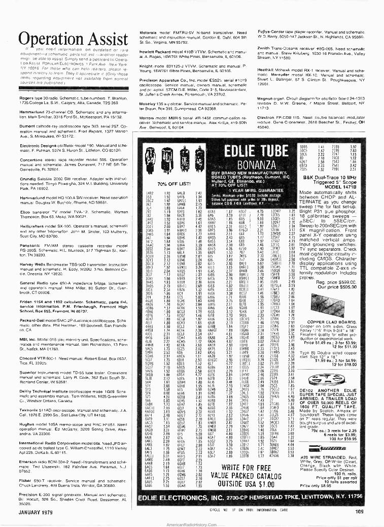
operation Assist If you need information on outdated or rare
equipment -a schematic parts list. etc -another reader might be able to assist Simply send a postcard to Opera- tion Assist POPULAR ELECTRONICS 1 Park Ave . New York. NY 10016 For those who can help readers. please re- spond directly to them They ll appreciate it (Only those items regarding equipment not available from normal sources are published I
Rogers type 30 radio. Schematic, tube numbers. T. Branton, 1735 College La. S.W., Calgary, Alta. Canada, T2S 269.
Hammarlund 23 -channel CB. Schematic and any informa- tion. Mark Sinchar, 3316 Ford St., McKeesport, PA 15132.
Dumont cathode-ray oscilloscope type 303, serial 257. Op- eration manual and schematic. Fred Repent, 1327 Marion Ave., S. Milwaukee, WI 53172.
Electronic Designs oscillator model 190. Manual and sche- matic. F. Putman, 5374 S. Huron St., Littleton, CO 80120.
Concertone stereo tape recorder model 505. Operation manual and schematic. James Dunavant, 717 NE 5th Ter. Gainesville, FL 32601.
Grundig Satellite 2000 SW receiver. Adaptor with instruc- tions needed. Tonyo Poweigha, 324 M.I. Building, University Park, PA 16802.
Hammarlund model HO 100 A SW receiver. Need operation manual. Douglas W. Bucholz, Rhame, ND 58651.
Elico transistor TV model TVA -12. Schematic. Wyman Thompson, Box 63, Mead, WA 99021.
Halllcrafters model SX-100. Operator's manual, schematic and any other information. John M. Snider, 103 Mulberry, Scott City, MO 63780.
Panasonic FM/AM stereo cassette recorder model RS -280S. Schematic. H.L. Murdock. 517 Tilghman St.. Ken- ton, TN 38233.
Harvey Wells Bandmaster TBS-500 transmitter. Instruction manual and schematic. H. Eddy, W2BU, 3 No. Belmont Cir- cle, Oneonta, NY 13820.
General Radio type 650-A impedance bridge. Schematic and operator's manual. Mike Miller, 80 Sutton Dr., Glen - brook, CT 06906.
Friden 1154 and 1102 calculator. Schematic, parts Ilst, service information. P.M. Erlenbaugh, Fremont High School, Box 655, Fremont, IN 46737.
Packard -Bell model SMC-2P dual -trace oscilloscope. Sche- matic. other data. Phil Hartman, 169 Boutwell, San Francis- co. CA
MBI, Inc. Model 015 disc memory unit. Specifications, sche- matics and maintenance manual. Bert Richardson, 13 Fern St., Natick, MA 01760.
Concord VTR 600-1. Need manual. Robert Sloal, Box 0537, Tice, FL 33905.
Superior Instruments model TD -55 tube tester. Operations manual and schematic. Larry R. Cook, 362 East South St.. Richland Center, WI 53581,
DeVry Technical Institute oscilloscope model 1G09. Sche- matic and assembly manual. Tom Williams, 1625 Greenview Cr., Windsor Ontario, Canada.
Tektronix 511 AD oscilloscope. Manual and schematic. J.A. Call, 1876 E. 2990 So., Salt Lake City, UT 84106.
Hughes model 105A memo -scope and HAC H1051. Need operation manual. Ed McGarry, 3209 Spring Drive. Alex- andria. VA 22306.
International Radio Corporation model 66x. Need JFD air- cooled ac -dc ballast type C. William Christoffel, 1110 Varsity Apt 225, DeKalb, IL 60115.
Emerson radio 8CW-334-2. Need i -f transformers and sche- matic. Ted Ltszewski, 182 Fairview Ave, Paramus, N.J. 07652.
Fisher 550-T receiver. Service manual and schematic. Chuck Landresy, 409 Buena Vista, Windor, GA 30680.
Motorola model FMTRU-5V hi -band transceiver. Need schematic and instruction manual. Gordon E Dahl, 604 9th St. So.. Virgins, MN 55792.
Hewlett Packard model 410B VTVM. Schematic and manu- al. A. Reges, 16W761 White Pines. Bensenville, IL 60106.
Knight model 83Y125 -J VTVM. Schematic and manual. P.
Young, 16W761 White Pines, Bensenville, IL 60106.
Precision Apparatus Co., Inc. model ES525. serial #1019 oscilloscope. Service manual, owners manual, schematic and pc layout. STCM D.E. Miller. Code 915, Nayseacenlant. St. Jullen's Creek Annex. Portsmouth, VA 23702.
Moseley 135 x -y plotter. Service manual and schematic. Pe- ter Braun, Box 399, Sunnymead, CA 92388.
Morrow model MBR-5 serial #R-1458 communication re- ceiver. Schematic and service manual. Alex Kiriluk, 419 -50th Ave., Bellwood, IL 60104.
Fu)lya -Corder tape player recorder. Manual and schematc. W.D. Barry, 5050-147 Jackson St., N. Highlands, CA 95660.
Zenith Trans-Oceanik receiver #8G-005. Need schematic and manual. Steve Kritzberg, 1030-16 Franklin Ave.. Valley Stream, NY 11580.
Heethklt Mohawk model RX-1 receiver- Manual and sche- matic. Marauder model HX-10. Manual and schematic. Stuart L. Ballinger, 57 S. Clinton St., Poughkeepsie, NY 12601.
Magnus organ. Circuit diagiarm for oscillator board 24-1353 revision D. M.W. Greene, 7 Maple Street, Bellport, NY 11713.
Olektron FP-CDB-115. Need double -balanced modulator module. Gene Cronenwett, 2618 Beecher St., Findlay, CH 45840.
y°
lAD2 183 I BC2 163 IU4 1V2
1X2
2AH2 2AV2 2D21 2065 21195 393 3AT2 3AW2 3662 3826 3CU3 3CY3 3DC3 3DF3 3013 3117 3065 31165
3805 3106 3616 3V4 4486 4816 4C86 4086 4016 4EH7 4E11
41145 4HS8 4106 41116
4U8 4M68 5405 544 5GH8
e` 5617 50196 5GS7 5H26
s- 5608 5U8 504 594 593 544 523 6A8 6AB4 6ACI0 6ADI0 6614 6AF9 6665 6AG7
6AG9 6AH6 6618 6665 6668 6613 6AL5 60111 6AM8 6AN8 6605 6608 6605 66011 6885 6AU6
70% OFF LIST!
.82
.92
.97
.92
.83
.19
.94
.92
.52
.00
.91
.64
.94
.88
.94
.04
.73
.36
.12
.12
.97
.04
.77
.86
.85
.73
.34
.86
.88
.80
.70
.37
.60
.15
.80
.80
.50
.74
.31
.01
.22
.82
.13
.52
.37
.13
.52
.10
.52
.88 .12 .61
.66
.58
.00
.26
.00
.70
.09
.89
.40
.11
.85
.04
.21
.99
.67
.28
.92
.75
.56
.01
49
64 13 26 6GM6 75 6GS7 15 6GÚ7 56 6GW8
6AU8 6696 66911 6AW8 6694 6913 6828 61310
6866 68A7 68811 68E6 68116 61316
6844 6BK7 6818 6BM8 6BN6 6BN8 68NII 6005 6807 6008 6868 6BV11 6026 6C4
6CÁ4 6C47 6C86 6CG3 6CG7 6CG8 6CH3 6C13 6CL6 6018 6CW4 6CW5 6C08 6C25 606 6006 6Dí8 6915 6D05 6006 6DS4 6016 6DW4 60X8 6E5 6E68 6EB8 6EH5 6E117
6E17
6EM5 6EM7 6EB8 6EÚ7 6EW6 6EW7 615 616 6166 6167 6FM7 6105 66E5 6617 66118 6017 6666
EDLI°E TUBE d = r'.: BONANZA
BUY BRAND NEW MANUFACTURERS 1,"YBOXED TUBES -(Raytheon, Dumont, IEC
Mallard, GE, Elmenco, etc.) ' ° '
;
2.42 1.34 1.91 2.15 1.13
"-AT70% OFF LISí! qr 1 YEAR MFRS. GUARANTEE
Terms: Minimum order $10.00. Include oostage. Eithea.full payment with order or 38.k deposit,
'balance. C.0.0,1 0.8. Levittown: N.Y.: -
1.82 66X6 1.67 6607 4.75 2DW7
3.56 6116 3.59 6110 1 2.70 21X5
2 45 61185 1.85 605 9.00 26E5 1.61 61137 1.86 1.88 2687 4.47 61115 2.31 6UÍ0 ! 1.91 21117
2.36 61115 3.96 696GT 2.21 2186
1.71 61118 2.51 6X4 1.73 2MD8
1.82 6H05 2.43 6X5 1.71 2567 1.88 611$5 3.54 608 1.97 2507 3.59 611S8 2.30 6X9 2.46 2110 2.36 61495 4.26 6210 2.93 3FM7
1.35 6H26 1.53 787 5.40 3110
2.01 615 3.87 1616 2.33 48111
2.24 616 2.49 797 4.20 48011 2.02 6110 2.93 8819 5.61 5BDII 3.24 6111 3.03 86011 3.38 5CW5
1.91 61A5 2.37 BAW8 2.48 5008 2.31 6186 2.90 88611 2.70 5618
2.42 6106 2.15 8BM11 3.50 5MF8 2.36 6176 2.21 88011 2.85 668 2.69 61E6 4.02 88011 2.82 67158 1.52 6116 3.32 8011 3.41 7AY3
1.91 6166 3.38 8CG7 1.46 78E3
5.00 61116 1.71 8168 1.58 7BFU
1.83 61118 2.75 8198 2.22 7803 2.84 61M6 2.61 8118 1.95 7BW3 1.59 6186 2.43 9GH8 1.91 7C13
1.79 6156 3.12 91W6 1.52 1DW4
1.46 6118 2.73 9696 2.33 7EW8
1.97 61116 3.23 0CW5 1.11 7186
1.65 6108 2.13 0008 1.46 71M6
1.94 61W8 1.64 0617 2.51 7156
2.36 66661 1.89 OGK6 2.18 7128
2.34 667 4.61 OGN8 2.31 7696 5.45 66A8 2.34 OG98 1.88 9CG3
1.72 6K06 4.07 0118 3.02 20A03 2.69 66E8 2.93 0158 1.50 20116 2.02 6618 2.61 0608 2.33 21055 2.82 6696 3.21 1619 3.20 21H05 1.61 6618 1.97 IBM8 2.43 21156 2.50 6L6GC 2.93 18011 3.29 21126
1.52 617 4.77 1E1111 3.62 21108 2.40 6186 3.87 1DS5 2.24 21188 2.58 61E8 2.19 IFY7 2.06 22116 4.77 6116 3.84 IHM7 2.46 22106
1.59 6118 2.82 1698 2.66 2329 1.80 6116 3.48 1108 2.49 241E6
1.55 6118 2.15 19168 2.04 25C5 5.99 61M8 2.34 2605 1.76 25CG3
1.91 6158 1.31 2015 1.92 25EH5
2.81 6106 3.69 2805 1.63 261105
1.52 61118 2.84 2A16 1.43 27 1.85 6118 1.91 2AT7 1.65 27685 1.76 61118 2.33 2606 1.64 306E3
2.02 6108 1.32 2AU7 1.41 31156
2.72 6108 2.02 2696 1.41 31126 2.70 6M11 3.30 2697 2.21 33617 1.83 6MI18 2.82 2AX7 1.52 34CE3
1.13 6ME8 2.19 2827 1.91 35C5 2.75 6MÚ8 2.81 2866 1.40 3516
5.00 607 4.80 2BE6 1.26 35106 5.00 6SA7 4.80 26111 2.85 3584 1.65 6067 3.75 1BH7 1.92 3525
2.60 6517 3.50 11357 1.11 36606 2.22 66K7 4.25 2926 2.40 388E7 2.22 6S17 2.60 2006 2.61 38HK7
2.61 6557 1.86 2018 1.11 426916
2.55 1.52 1.73 1.10
WRITE FOR FREE 2.02 2.10
VALUE PACKED CATALOG 2.02 1.93 OUTSIDE USA $1.00
1.15 1.61
2.42 2.70 2.34 3.12 2.21 4.75 4.15 2.81 1.97 3.08 3.54 2.90 2.70 1.11
1.92 3.50 2.72 2.49 3.59 1.82 1.82 2.88 1.64 1.64 1.67 1.82 1.28 2.73 2.91 1.63 2.04 3.50 1.89 1.71
3.96 2.45 2.36 4.32 2.54 2.39 2.39 3.20 3.41 2.58 3.84 1.85 1.67 1.71 4.40 5.40 1.67 1.86 3.48 4.07 3.11 1.92 1.47 2.27 3.69 1.22 1.64 4.04 3.53 3.53 3.38
P $ s
50135 1.41 7189 1.97 5005 1.47 7199 2.63 5016 2.22 7247 1.85 80 2.10 7408 1.92 6267 1.58 1543 1.64
6973 2.33 7581 3.42 7025 1.52 7591 2.51
B&K Dual -Trace 10 MHz Triggered 5" Scope
MODEL 1471B Mode automatically shifts between CHOP and AL- TERNATE as you change sweep time for fast set-up. Bright P31 blue phosphor. 18 calibrated sweeps - µSEC/ to .5SEC/cm. Sweep to 200nSEC/cm with 5X magnification. Front panel X -Y operation using matched vertical amps. Input grounding switches. TV sync separators. Check most digital logic circuitry in- cluding CMOS. Character display applications using TTL compatible Z-axis in- tensity modulation. Includes probes.
Reg. price $599.00. Our price $505.00
COPPER CLAD BOARDS. Copper on both sides. Glass Epoxy 1/16' thick 9-3/4" x 18" Excellent quality for either pro- duction or experimental work.
Price S1.49 ea.; 3 for $3.99; 12 for $11.99
Type B) Double sided copper clad. Size 12" x 18"
$1.99 ea.; 3 for $4.99; 12 for $18.00
DE102 ANOTHER EDLIE SUPER TAPE SPECIAL JUST ARRIVED. A TRAILER LOAD OF OVER 50,000 REELS OF 1800 FT. QUALITY TAPE. Made by Scotch, Ampex or Soundcraft. These tapes come on 7" reels regular. They were bought surplus and are of excel- lent grade.
790 ea.; 3 reels for 2.25 6 reels for S3.99;
100 for $59.95
ísszunim #20 WIRE STRANDED. Red, White, Grey, OH -White (Clear), Orange, Black with White. Please Specify Color Desired.
,00 ft. rolls. Price only $1 per roll
10 rolls assorted Price only 58.95
:at
"21 ."1
.;
Precision E-200 signal generator. Manual and schematic. Bill Hocutt, 926 So., Shades Crest Road, Bessemer, AL 35020.
JANUARY 1979
ÉDLIE ELECTRON IC. $; INC°.2700-CP HEMPSTEAD TPKE,LEVITTOWN, N.Y-'11'756-
CIRCLE NO, 17 ON FREE INFORMATION CARD 109
AmericanRadioHistory.Com

KIM -1 MICROCOMPUTER
Fully ^' , i AssembledcitS. & Tested 'II
517900 a
J Including Documentation
Ballantine Model 1010A Dual Channel/X-Y Scope A professional oscilloscope
- to fit
I f' F your
basic I r
R needs.
'.,f! i.g, flá'!i- $695
Intersil LED or LCD 31/2DIGIT PANEL
METER KITS BUILD A WORKING UPM IN 1/2HOUR
THESE COMPLETE EVALUATION
t niivob. teat a.1Ivoeon»nme dLCOaiso IIa 1 w LEO 4seus nor Me Mob. am mai.nala,aaamtQ PCaaaa,I0,awaeani emanaonmer
ICL71oeru (LCD) $29.95 ICL7r07 (LED)
a,..,. ; .."'-- 00
WITH 4';_'++4" KITS "... 7
r Et, '11 $24.95
The Instructor 50- Dodgem Compute,
- from SIGNETICS
a_. . i, Microprocessor
535000 .. ''t Includes and
_ grams.
Complete, Ready -To -Use Learning Package
everything you need to write, debug machine -language pro.
Housed In one compact package.
- S U P E R K I M .. $395.00 (FLUKE]
lr 1 _
1 La
-,
lator
-1 Economical morepansiOnR Into
e RAM,
yl - ar EPROM and
one me
era .,I ode. act fully
1
(F : and Integrated I: I Total compadbinty
with KIM -1 -P-- -- On board d TTY, RS232 and Audio Tape
a\tf,
user .1.
Model pro- 8020A
$169 a mbletl
board. .- ty. ,s1
Vá..11 lJ software.
5V, 3A reP L F
Interfaces.
/1.- '
.tr", - 4 e. HYBRID AUDIO
POWER AMPLIFIER P/N !,' 4
'Greg SI.1010GI1OWI 7. SI.1020G(20W)
A-SI-B(Socket SI.1030GI30W) SI.1050G(50W) A.SI.10(Socket
Note: One Transformer can
Matching Power Trait oformer
5 6.95 TRIO $ 7.90 $13.95 TR20 510.90
for abovel .95 019.00 TR30 $12.90 $27.80 TR50 $17.90'
for above) .95 power two audio amplifiers.
FUNCTION GENERATOR XR2206K8
Includes all corn- Portents, PC board
and Instructions. $19.95
KIT XR2206KA Includes chip.
PC board and instructions.
514.95
SYM-1 á camalate
GRI-ASCII KEYBOARD KIT 753K Keyboard $59.95 756K Keyboard $64.95 701 Enciosure(753 only1S14.95 702 Enclosure (both) $29.95
MIC i.i¡.y' -.Compvt0er E System
- -
a
5269.00 -'- 5% CARBON
RESISTORS All values from 1057 to 10 M2- Only
FILM $1.6 9
$; 79 in multiples of 100 pcs per value
ANCRONA HAS THE SOURCERERTM
13 STANDARD 8K RAM 64 Characters ' 64 User Graphic to S100
OPTIONS: Expandable to 32K RAM Storage -Telephone -Voice -Home
COMPUTER
58950° FEATURES: 280-4K ROM -
-Dual Cassette 1/0-30 Lines of -64 Defined Characters and
Defined Characters -512 x 240. Resolution -Edge Card Connection Bus -Serial and Parallel 1/O
-8 -Slot 0100 Bus -Printer -Disk Controller
OPCOA- RED/GREEN LED LAMP Changes red to green with biasing change
1-24 25 up 100 CSL31OL 0 1.40 5 1.105
ep .95
EXAR 1-24 25 up XR-555CP $ .45 5 .35 XR-556CP .85 .71 XR-567CP 1.12 .96
ob U¡1X
11
1.24 25 up 100 ICL6038CCPD $ 4.45 $ 3.75 $ ICM7216A111 30.00 24.00 20.00 ICM7216B1 P1 24.95 20.05 16.65 ICM7216C1J7 24.97 19.98 16.65 ICM721601P1 20.00 16.00 13.35 ICL7106CPL 14.70 11.75
up 3.13
9.80
XR.2206CP 4.40 3.74 R-2207CP 4.28 2.83
XR 2208CP 5.20 4.55 XR-2211CP 5.25 4.47 XR-2212CP 4.37 3.72 XR.2264CP 4.24 3.71 XR-2265CP 4.90 4.28 XR.2567CP 2.76 2.35 XR-4136CP 1.22 1.04 XR-4151CP 2.85 2.43
ICL7107CPL 13.85 11.10
ADTECH POWER SUPPLIES Model Rating Number Vdc amps Price APS5-3 5 3 935.50 APSE -2.5 6 2.6 35.50 AP512-1.6 12 1.6 35.50 APSI5.1,5 15 1.6 35.50 DAPS9.8 o5 0.8 46.00 DAPS12 5 x9 to 112 0.5 46.00 DAPS12.75 r12 0.75 46.00 OAPS15-.60 115 0.60 46.00
9.25
18 0 2 CERAMIC '55
to 125.0 180210 519.º5 18221D 1e 00 1824L0 7.75 1a52LD 8.25 185310 1.60 teseLD 1.70 185610 15 .SO
105710 5.50 1853LD 5.65 186910 5.65
SERIES EPDXY 40
to 85.0 1802LE 511.20 1822LE 8.05 1824LE 3.55 1853LE 1.as 18541E 1 50 1856LE 8.50 18561E 1.10 18571E 1.10 18581E 1A5 18591E IAS
-
P.O. Box 2208P, Culver dents add 6% sales tax. $1.00 to cover postage
Visa welcomed. Please Include your number and expiration data. PHONE
. ' _ .. r. Sendoney CheckOrer
to: d
City, CA 90230. California resi- Minimum Order; $10.00. Add
and handling. Master Charge and charge card number. Interbank
ORDERS (2131 641-4064 ARIZONA ANCRONAANCRONA
716021 51117:11'
CALIFORNIA
10031'Y390_Osan 0
CALIFORNIA ANCRONA
-lore, 547.0403
OREGON ANCRONA
seal E4ó641°
CANADA.
B.CALIFORNIA M156'RONSC
local 324-0707
ANCRONA
5.14081 24141311
GEORGIA ANCRONA
A1404I '531-710010Oa
TEXAS ANCRONA
' 17131n .52.344911
fi.
Electronics Library
THE HOME COMPUTER REVOLUTION by Ted Nelson
This book concerns itself with the "why" of home computing and provides interesting in- sight to many facets of this infant industry. The beginning computer hobbyist and those casually interested will find much information on the development and applications of home computers. Likewise, there are many fresh ideas and interesting facts within its pages which will fascinate established computer hobbyists. Distributed by The Distributors, 702 South Michigan, South Bend, IN 46618. 224 pages. $2.00 soft cover.
UNDERSTANDING AMATEUR RADIO by Jay Rusgrove, Doug DeMaw and George
Grammer
The American Radio Relay League has pub- lished a totally revised edition of the vener- able book Understanding Amateur Radio. Advances in the state of the art are reflected in the new edition, which is in a larger (81/4 x
101/2 in.) and more graphic format. After pre- senting some electronic fundamentals, the book explores semiconductors and vacuum tubes, CW and phone transmitters, receivers, antennas and feeders, the workshop and test bench, building receivers, accessories for your receiver, building transmitters, transmit- ting accessories, the power supplies, making measurements, antennas and masts, and setting up a station. Published by the American Radio Relay League, 225 Main Street, Newington, CT 06111. 223 pages. $5.00 (soft cover) in the U.S., $5.50 elsewhere.
MICROPROCESSOR INTERFACING TECHNIQUES
by Austin Lesea and Rodnay Zaks
This work describes the techniques and com- ponents used for interfacing a microproces- sor" -based CPU to all major peripherals. Fol- lowing an introductory discussion of basic concepts, techniques, and bus systems, as- sembly of the CPU is covered for four popular microprocessors. A chapter on basic I/O sys- tems precedes the essential part of the text, Chapter IV. It is here that the authors relate how to interface the microprocessor -based CPU to a keyboard, LED indicators, teletype- writer, paper -tape reader, cassette -tape re- corder, floppy disk, and CRT display. Published by SYBEX Incorporated, 2161 Shattuck Ave., Berkeley, CA 94704. 348 pages. $9.95 soft cover.
STATEMENT OF OWNERSHIP, MANAGEMENT AND CIRCULATION (Required by 39 U.S.C. 3685). 1.
Title of Publication: Popular Electronics. A. Publication No. 438240. 2. Date of filing: October 1, 1978. 3. Fre-
quency of issue: Monthly. A. No. of issues published annually: 12. B. Annual subscription price: $13.00. 4.
Location of known office of publication: One Park Av- enue, New York, New York 10016. 5. Location of the
Headquarters or General Business Offices of the pub- lishers: One Park Avenue, New York, New York 10016. 6. Names and complete addresses of publisher, editor, and managing editor: Publisher, Joseph E. Mesics, One Park Avenue, New York, New York 10016; Editor, Ar- thur P. Salsberg, One Park Avenue, New York, New York 10016; Managing Editor, John R. Riggs, One Park Avenue, New York, New York 10016. 7. Owner: Ziff - Davis Publishing Company, One Park Avenue, New York, New York 10016; Ziff Corporation, One Park Av- enue, New York, New York 10016. 8. Known bondhol- ders, mortgagees, and other security holders owning or holding 1 percent or more of total amount of bonds, mortgages or other securities: None.
10.
Extent and
nature of
circulation
Average
no. copies
each issue
during
preceding
12 months
Actual no.
copies of
single issue
published
nearest to
filing dale
A. Total No. Copies Printed (Net Press Run) 507,200 511,499
B. Paid Circulation 1. Sales through
Dealers and Carriers, Street Vendors and Counter Sales 85,271 81,200
2. Mail Subcriptions 332,370 331,100
C. Total Paid Circulation (Sum of 1081 and 1082) 417,641 412,300
D. Free Distribution by Mail, Carrier or Other Means Samples, Com- plimentary, and Other Free Copies 10,984 10,152
E. Total Distribution (Sum of C and D) 428,625 422,452
F. Copies not distributed 1. Office Use, Left Over,
Unaccounted, Spoiled After Printing 2,912 5,138
2. Returns from News Agents 75,663 83,909
G. Total (Sum of E, Ft and 2 -should equal net press run
shown in A) 507,200 511,499
11. I certify that the statements made by me above are
correct and complete.
WILLIAM L. PHILLIPS, Assistant Treasurer
12. For Completion by Publishers Mailing at the Regular Rates: (Section 132.121, Postal Service Manual)
39 U. S. C. 3626 provides in pertinent part: "No person who would have been entitled to mail matter under former section 4359 of this title shall mail such
matter at the rates provided under this subsection unless he files annually with the Postal Service a
written request for permission to mail matter at such
rates."
In accordance with the provisions of this statute, I hereby request permission to mail the publication named in item 1 at the phased postage rates presently authorized by 39 U. S. C. 3626.
WILLIAM L. PHILLIPS, Assistant Treasurer
110 CIRCLE N0. 4 ON FREE INFORMATION CARO
POPULAR ELECTRONICS
AmericanRadioHistory.Com

Original Japanese Replacement Parts for TV, Stereo and CB
F`
25 -UP 110.24 I 1.9 ., 25 -UP l 10.241 1-9 25 -UP I 10-24 11-9
_`1 . - L . ,.. . a 7 . . . . I .
2SA102 .29 .34 .39 .50 .55 25C1114 3.40 3.60 3.80 2SA473 .45 .55 .60 1.35 1.45 '1 :^.0 1116A 3.20 3.45 3.80 25A484 1.85 2.05 2.35 135 1.45 30C 1124 .80 .85 .95 2SA495 .25 .30 .35 1.35 1.45 0 :^;C1127 .80 .85 .95 2SA497 .90 1.15 1.25 .55 .60 25C1162 .70 .75 .85 2SA509 .30 .35 .40 .40 .45 1 2':C1166 .25 .35 .40 2SA562 .25 30 35 2SC517 290 3.10 3.25 1 ^::C11728 3.10 .3.50 3.85 2SA564A .29 .34 .39 .35 .40
Y 2:.C1173 .50 .65 .70 2SA634 .35 .40 .45! .50 .55 21:C1177 10.90 12.40 13.80 2SA636 .80 .85 .90 .40 .45 r ..^.:C1209 .25 .35 .40 2SA643 .30 .35 .40 .45 .50 ° :::C1226 .50 .60 .70 2SA673 .30 .40 .45 3.50 3.90 2:21226A .50 .60 .70 2SA678 .40 .50 .55 .27 .30 ' 25C1237 1.70 1.90 2.15 2SA683 .40 .50 .55 .27 .30 S 2::C1239 2.70 2.65 2.85 25A684 40 .50 55. 27 .30 2::C1306 125 1.65 1.85 2SA695 .40 .50 .55 C .40 .45 _5C1307 2.15 2.65 2.85 2SA699A .50 .60 .65 3.15 3.35 ° 2::C1318 .30 .40 .45 2SA706 .85 .95 1.05 .25 .30 .12::C1364 .30 .40 .45 25A720 .30 .35 .40 . 25 .25 .30 .'2::C1383 .30 .40 .45 2SA733 .25 .27 .30 25C73 .25 .30 A 25C1384 .30 .40 .45 2SA747 4.15 4.35 4.85 20 .25 .30 :::C1424 2.75 2.85 2.95 25822 .45 .50 .556 1.75 1.95 ' '..1..0 1448A 1.00 1.10 1.20 25854 .30 .35 .40 2.10 2.20 211C1475 .65 .85 .95 25877 .30 .40 .45 3.10 3.30 0, 75C1509 .55 .60 .65 250175 .35 .40 .45 2.15 2.45 71:C1567A .60 .65 .75 258186 .20 .27 .30 .35 40
P 2::C1675 .25 .30 .35
258187 .20 .27 .30 .85 .95 ..r25C1678 1.25 1.40 155 258324 .25 .35 .40 2.15 2.45 7:.C1687 .40 .45 .50 258367 1.10 1.20 1.35 2.15 2.45 2:.C1727 1.20 1.25 1.30
r 293405 25 .30 .35 .27 .30 2::C1728 .90 .95 1.00 258407 .70 .85 .95 2SC829 .27 .30 29:C1760 .85 1.00 1.10 258463 1.00 1.05 1.15 .35 .40 2' 2:.C1775 .30 .35 .40 258474 .70 .80 .90 4.25 4.50 21 C1816 1.45 1.70 1.95 2613507507 .70 .80 .90 .27 .30 ?:.C1908 .25 .35 .40 258511 .70 .75 .85 27 .30 " 7:.C1909 2.00 2.55 2.75 2S8557 2.05 2.45 2.75 .27 .30 25C1945 4.40 490 5.50 25C 183 .40 .50 .55 40 .45 ' 75C 1957 .60 .70 .80 2SC184 AO .50 .55 .60 .65 ' 25C1969 350 3.90 4.30 25C372 .20 .27 .30 .60 .65 ' 25C1973 .60 .65 .70 25C373 .20 27. .30 .75 .85 ° 25C1974 1.25 1.65 1.85 25C 5.30 20 .27 30 2.05 2.35 . 75C1975 125 1.65 1.85 25C382 .30 .40 .45 4.70 4.90 D,. 23.C2009 .75 .80 .85 2SC387A .30 .40 .45 .75 .85 ': 25C2021 .55 .60 .65
2SC394 .25 30 .35 .80 .90 75C2028 50 .60 .65
2SC458 .20 .27 .30 .50 .55 ' 75C2029 1.45 1.75 1.95
20
25C1018 .70
ai 2SC460 .45 2SC481 1.25 2SC482 1.25
25C485 1.25
2SC495 .45
2SC509 .30
2SC535 .30
2SC620 .45
0 2SC632A .35
2SC634A .40
'
2SC697A 3.20 2SC710 20 2SC711 20 2SC712 .20 2SC717 .35
2SC730 2.95
2SC732 .20
C733 .20
4. 4 20 2SC735
'qI 2SC7561.45 2SC756A 2.00 25C778 2.80 2SC781 1.95
n 2SC784 .30
25C789 .75 ^ 25C793 1.95
2SC799 195 2SC828 .20
o 2SC839 .30
° 2SC867A 4.00 2SC900 .20
.+ 2SC930 .20 25C945 20
2SC10008L .35
25C1013 .45
25C1014 50 r '1 2SC 1030 1.80 , 2SC1056 4.50
TSC1060 65 ". 25C1061 .70 .' 25C1096 .45
áº
2SC 2072 2SC 2076 2SC2091 2SC2092 2SC2098 25072 25091 25D92 250180 250187 250218 250234 250235 250261 250287 250291 250313 250315 2513325 250330 25D356 250358 2SD359 2SD427 250525 2513526 25109 25K23 2SK30 2SK33 2S K 34 2SK41 25455 35K 22V 3SK35 3SK 37 35K40 35K41 3SK45 35K48 3SK49 AN 115 AN2140 AN 228 AN 239
25-UP110.24 1 1-9
3.55 .45 .85
1.75 3.00
.50 1.30 1.40 1.55
.30 2.95
.60
.60
.30 2.50 2.05
.60
.60
.60 .69 .70 .70 .75
1.75 .70 .60 .45 .80 .40 .60 .50 50 .60
1.60 1.20 1.70 1.25 1.25 1 25 3.30 1.25 2.00 1.55 4.10 4.10
3.75 .60
1.05 1.95 3.20
.60 140 1.55 1.75
40 3.20
.70
.70
.35 2.65 2.45
.65
.70
.65
.79
.75
.80
.85 1.95 1.05 .70 .50 .95 .45 .65 .55 .55 .65
1.70 1.35 2.00 1.40 1.40 1.40 3.40 1.40 2.15 1.65 4.30 4.30
3.95 .65
1.15 2.20 3.45
.65 1.55 1.75 1.95
.45 3.45
80 .80 .40
2.85 . 2.75
.70
.80
.75 0.
.89
.80
.90 .p
.95 3 MN3002 2.20 : MN3003 1.15 PLLO1A
.80 -' PLL02A
.55 - PLL03A 1.05 SG264A
.50 - SG609
.75 - SG613
.60 - SM5104
.60 A STKO11
.75 STK013 8.90 1.80 - STK015 4.10 1.50 STK050 23.10 2.30 STK415 7.10 1.55 , STK435 4.45 1.55 STK439 8.00 1.55 _ TA7045M 1.95 3.70 TA7055P 1.95 1.55 TA7060P .85 2.25 TA7061P .85 1.85 _ TA7062P 1.05 4.50 , TA7063P 1.25 4.80 i TA7074P 3.70
25 -UP] 10-24 I 1-9
AN247P 2.40 AN274 1.50 AN313 4.20 AN315 1.75 BA511A 1.70 BA521 1.85 HA1151 1.40 HA1156 'I.60 HA 1306W 1.90 HA1322 2.40 HA1339 3.45 HA1339A 2.45 LA1222 2.10 LA3101 3.45 LA4031P 1.75 LA4032P 1.75 LA4220 2.25 LA4400 1.85 LD3141 1.70 M5115P 4.85 M51513L 1.95 MN3001 13.20
6.25 5.64 4.00 4.95 7.50 7.00 4.10 5.05 7.90
2.60 2.90 "'w-
1.70 1.90 '
4.40 1.95 2.20 .á 1.90 2.15 %
2.05 2.35 ?
1.70 1.85 ;e 1.75 1.95 2.10 2.40 2.60 2.90 2.65 2.95 2.65 2.95 2.30 2.50 3.60 3.75 1.95 2.20 1.95 2.20 2.40 2.55 2.05 235 1.80 1.90 4.90 4.95 2.15 2.45
14.85 16.50 10.40 11.55 6.34 7.04 4.15 4.55 5.20 5.80 7.90 8.70 7.40 790 ,
4.30 4.50 7
5.45 5.85 eR 8.40 8.90 :o
3.95 4.35 . 10.00 11.10 4.30 4.80 n
25.98 28.86 7.60 8.10 4.95 5.55 9.00 10.00 2.15 2.45 2.15 1.05 1.15 1.05 1.15 $ 1.20 1.35 1.35 1.50
m
3.85 4.00
25 UPI 10-24 I
1-9
PRICES MAY CHANGE WITHOUT NOTICE COD ORDERS WELCOMED
`r
f ' ` y'b;r.a, :Y,,w ' / ; IMMEDIATE DELIVERY WITHIN 48 HOURS' 5{ ,;° ?Minimum bider $10.00. N.J: Résidents add 5% Sales lkx.'° ; - .
e+. ';, :We pay'postage for' prepaid' orders of $50.00 or more, nn .;,,$.9?, P,-; 2,._ .',,:+;; f.. .
° y pryALL TRANSISTORS IN STOCK 5.; q e- º 1770. 2-e. _- --
._ 6. 5':. _. _e B.:E _ -- -Under $50.00, add $1.00; Canada $1.50. Quantity Discount Prices - Ask for bur complete price !tat = =,g'1 +:"'' ¡A '
-° Manufacturer inquiries we'come All parts guaranteed_', ¡. ' a7 ` ///\\
``o':`:, q., TOLL'FREE._TÉLÉPHONEa. 'lyátionwide:800/6311125Ó,.s Local 201/748-5')89;.
HOURS: :Mon:n,Fri.18tó5:30.-Sat. 85,ák 5 ;
TA7089P 1.95 TA7092 4.40 TA7120P 1.45 TA7139P 1.55 TA7153P 5.70 TA7203P 2.45 TA7204P 1.95 TA7205P 1.55 TA7214P 3.90 TA7310P 1.25 TA7607P 5.80 TA7609P 4.40 TBA8105H 1.85 TC5080P 4.80 TC5081P 2.90 TC5082P 3.30 UH IC001 4.90 UHIC002 4.90 UHIC003 4.90 UHIC004 4.90 UHIC005 4,90 UHIC006 4.90 UPC20C 2.00 UPC141C 2.30 UPC157A 325 UPC554C 1.60 UPC555H 1.60 UPC572C 3.70 UPC574C .90 UPC575C2 1.25 UPC576 1.85 UPC592H2 .75 UPC1001H21.85 UPC1008C 4.85 UPC1020H 1.85 UPC1025 1.85 UPC1028 1.40 UPC1031H 252 UPC1032H 1.70 UPC1152H 2.90 UPC1156 1.85 UPD277C 8.70 UPD857C 7.90 UPD858C 7.00 UPD861C 8.70
INTERNATIONAL - ;,F.;. MM
.t a:': ,J.ie .:,J.\''F'(- - -i, CIRCLE NO. 35 ON FREE INFORMATION CARD
2.15 4.90 1.65 1.75 5.90 2.60 2.10 1.75 4.20 1.40 6.00 4.60 2.05 5.00 3.10 3.45 5.10 5.10 5.10 5.10 5.10 5.10 2.40 2.40 3.45 1.70 1.70 4.10 1.08 1.40 2.05
.85 2.05 5.15 2.05 2.05 1.62 2.74 1.85 3.10 2.05 8.90 8.30 7.10 8.90
NEW -TONE ELECTRONICS INTERNATIONAL P. O. Box 1738, Bloomfield, N. J. 07003
New Jersey Phone: 201/748-6171
2.45 5.40 1.85 1.95 6.10 2.85 2.45 1.95 4.50 1.55 6.20 4.80 2.35 5.60 3.30 3.80 5.60 5.60 5.60 5.60 5.60 5,60 2.70 2.50 3.65 1.80 1.80 3.69 1.20 1.55 2.35
95 2.35 5.75 2.35 2.35 1.80 2.98 2.10 3.30 2.35 9.10 9.40 7.20 9.10
a'
JJIRECT:,FROM JAPAN'S B
ul 3S
250
,116'1; 2.0i
.35
35
32.1"21 22
050
rweiv
2 952 2444141
OMms
1uan
0.1041
ú/1111 w '3U 401
] ELECTRONICS SUPPLIER
750311/ 35C .0
31
05,101.
7.110 256,242
.42 Mc 042 256542
35,14
350,4 350,5
.35
.70 1503001
2:ói
x:á 3
TV, RA010, STEREO, SPARE PARTS KITS (with beautiful fitted case)
TRANSISTOR ia T V PEIe6 SP,.cN. 123 90 527500
DTVPE1114pe4.5.123pcyi S275110 DIODE . 55040 C Se, 1279d S14000
CR Se, 1419 951 . 510300
)50110
05.15
350.
310311
3.52 2540
63.v,.
1
'2; 1 05
01P IC TE I CLIP 15P
5300
j16.20546 :io
ló5nap
OS la
MO
ml
C; ::vs ,SÑ. ;
rIZTC 323
fil 1111
Al
en IOW 4.03
121:22: 3 is
EXTRA LENGTH TEST CLIPS NEW
n 1 n1^M
I RED. MI C eo.r4e BLACK 51.00 ena+tl 3"e.PN
or
"Queries an', orders should be sent direct to Ado Elaeironie, Japan' seen eec.neb.nnen lame do m445444<nde uSS2o 00 Seed poem 13ank monev 0514
Iv 01.31 412 JSS350 In, an 5,,1131J, hancll, per ore . 00.0,, u .o,er,
ADO ELECTRONIC INDUSTRIAL CO.LTD. ". Dee, Kdarawa Bldg. 10.7. Sorokanda 3.Chome. Ch,yoda.kur Tokyo 101. Japan. I
loin. 0222.4754' ADO J. .9T0í:.03.253.8303 Cable:.MIDNAINCD. TOKYO .,
CIRCLE N0. 2 ON FREE INFORMATION CARD
D. ° ' II -
AMAZING EARADID ".1.,. 1,41$ IS PROBABLY THE WORLD'S SMALLEST e
RADIO. IT WEIGHS ONLY 1/2 OUNCE AND ISQ ' '
WORN BEHIND THE EAR. CONTAINS AN IC AND 5.95 SEVERAL DISCRETE DEVICES TO GIVE AN EQUI- SALENT OF 12.TRANSISTOR5. THE RADIO HAS A T.R.F.
- - DESIGN OPERATING FROM 1 STANDARD S13E 1.5V ' HEARING AID BATTERY (INCLUDED). I1 PROVIDES
GOOD VOLUME TO EARPHONE ON SEVERAL STATIONS IN - METROPOLITAN AREAS. DOESN'T REQUIRE ANY ANTENNA,
á` o GROUND OR OTHER ADDITIONAL WIRES - FULLY SELF T. CONTAINED 8 TUNABLE. SIZE: I 1/81IÁ1 I/4"X3/8".
Crystal Oscillator 14.04 Mhz
.n 51.98
_
"O100 '2,002 8 foe S1 00
650 11 T .GG55 n
0ou aea Se _
..
Green Neon , .01 ,;" ̀ga
6,°. 5144.
1.14.0
21r1 pes e.eo,.CIO .00na.,kiÍ
1 79<
300 VOLT
1 1- 500
-. .... 1
1001VI PHOTOFLR/R Kit o o SIMPLE TO ASSEMBLE KIT INCLUDES PRE -ASSEMBLED
' CIRCUIT BOARD, CAPACITOR, FLASIITUBE, REFLECTOR, SWITCH AND HOOKUP DIAGRAM, LESS CASE, BATTERY HOLDER, C2343í
AND BATTERIES (OPERATES ON 52.95 ;1.2 AA CELLS). GUIDE 028 AT
ASA 25. / 1, á ,a1:
n41 14" IT1/00E !NUTTER CORO _Iectronie Warning Flasher Kit
1.11e.,0 0. :' - " i .m C03101 6.95 L
'7RIiY" PNOTOFL11/11 CRP/ (CALCULATOR {
BOARDS i .
WITH DISPLAY 111
1 LESS KEYBOARD 12 IV ,n
AND CASE IAS } 41
BE
I S! 51.50 fTRO TUBE RJIT I minimum
Boana new fac. RECtECT011 rV prime App.. 5110: 1.7/16-1 + robe ubes rY1
Assn tmenl 01 C23280 7/8"W K 3/413.
[11
Probe lobed, hCmdbCl $ 3.00 C23227 S 1.00
Minimum order $5.00
CHANEY Please include $1 for pdstage Visa, MC and COD accepted.
electronics Phone orders are welcome.
- P.O. BOO 27038. DENVER, CO. 80227 Ph: 13031973.1052
Send for Dut`FREE GIANT CATALOG of:unlooe dents
350 mt 330V 100
°e: 720 mf 360V 150
1600mf360V 52.25
' I 4 _.
soe. i
, 1`°
.:'
P
38ro
Years 'of Serrice! A
2
5.7
IENTIFIC ATALOG"
-B_ Explore Astronomy, Biofeedback, Com{Juters, Health, Lasers, -Magnets; Microscopes,:Optics,',:U
s' Photography, Weather...: Over 4,000 Fascinating Items,:
More Thah,160 Colorful Pages...., ,.
Thé Exciting, -'
-, °FREE' f- Edmund Catalog!
a e tee. 04
-y f"f' - No. 108°
Edmund Scientific Co. 197S
Yes! Rush me your FREE Catalog so that I can explore Edmund's Wodd of Science.
Name
Address
city
Stare Zip
Clip and Mail Coupon Today to: Edmund Scientific Co., AVO2 Edscorp Bldg., Barrington, N.J. 08007
L J AmericanRadioHistory.Com

Electronics C assifiec REGULAR CLASSIFIED: COMMERCIAL RATE: For firms or individuals offering commercial products or services, $2.50 per word. Minimum order $37.50. EX- PAND -AD® CLASSIFIED RATE: $3.75 per word. Minimum order $56.25. Frequency discount: 5% for 6 months; 10% for 12 months paid in advance. PERSONAL RATE: For individuals with a personal item to buy or sell, $1.50 per word. No minimum! DISPLAY CLASSIFIED: 1" by 1 column (2-1/4" wide), $300. 2" by 1 column, $600.00. 3" by 1 column, $900.00. Advertiser to supply film positives. For frequency rates, please inquire. GENERAL INFORMATION: Ad copy must be typewritten or clearly printed. Payment must accompany copy except when ads are to be billed on credit cards - American Express, Diners Club, Master Charge, VISA (supply expiration date) - or when ads are placed by accredited advertising agencies. First word in all ads set in caps. All copy subject to publisher's approval. All advertisers using Post Office Boxes in their addresses MUST supply publisher with permanent address and telephone number before ad can be run. Advertisements will not be published which advertise or promote the use of devices for the surreptitious interception of communications. Ads are not acknowledged. They will appear in first issue to go to press after closing date. Closing Date: 1st of the 2nd month preceding cover date (for example, March issue closes January 1st). Send order and remittance to Classified Advertising, POPULAR ELECTRONICS, One Park Avenue, New York, N.Y. 10016. For inquiries, contact Gladys Mathieu at (212) 725-3926.
FOR SALE
FREE! Bargain Catalog-I.C.'s, LED's, readouts, fiber optics, calculators parts & kits, semiconductors, parts. Poly Paks, Box 942PE, Lynnfield, Mass. 01940.
GOVERNMENT and industrial surplus receivers, transmitters, snooperscopes, electronic parts, Picture Catalog 25 cents. Meshna, Nahant, Mass. 01908.
LOWEST Prices Electronic Parts. Confidential Catalog Free. KNAPP, 4750 96th St N., St. Petersburg, FL 33708.
ELECTRONIC PARTS, semiconductors, kits. FREE FLYER. Large catalog $1.00 deposit. BIGELOW ELECTRONICS, Bluffton, Ohio 45817.
RADIO-T.V. Tubes -36 cents each. Send for free catalog. Cornell, 4213 University, San Diego, Calif. 92105.
AMATEUR SCIENTISTS, Electronics Experimenters, Sci- ence Fair Students ... Construction plans - Complete, in-
cluding drawings, schematics, pans list with prices and sources ... Robot Man - Psychedelic shows - Lasers - Emotion/Lie Detector - Touch Tone Dial - Quadraphonic Adapter - Transistorized Ignition - Burglar Alarm - Sound Meter ... over 60 items. Send 50 cents coin (no stamps) for complete catalog. Technical Writers Group, Box 5994, Uni- versity Station, Raleigh, N.C. 27650.
ROTARY SWITCH 4P11P 5/$5; 6P11P 5/$7.25. Dip Switch 10-SPST 10/S15. Transformers 12.2 V CT -6A plus 8.5V -5A $6.95. 24V -5A $5.95. 10' RG58C/U 12/510. Fertiks, 5400 Ella St., Philadelphia, PA 19120.
SOUND SYNTHESIZER KITS -Surf $14.95, Wind $14.95, Wind Chimes $19.95, Musical Accessories, many more. Catalog free. PAIA Electronics, Box J14359, Oklahoma City, OK 73114.
HEAR POLICE I FIRE Dispatchers! Catalog shows exclusive directories of "confidential" channels, scanners. Send post- age stamp. Communications, Box 56 -PE, Commack, N.Y. 11725.
UNSCRAMBLERS: Fits any scanner or monitor, easily ad- justs to all scrambled frequencies. Only 4" square $29.95, fully guaranteed. Dealer inquiries welcomed. PDQ Elec- tronics, Box 841, North Little Rock, Arkansas 72115.
TELETYPE EQUIPMENT for sale for beginners and exper- ienced computer enthusiast. Teletype machines, parts, supplies. Catalogue $1.00 to: ATLANTIC SALES, 3730 Nautilus Ave., Brooklyn, NY 11224. Tel: (212) 372-0349.
WHOLESALE C.B., Scanners, Antennas, Catalog 25 cents. Crystals: Special cut, $4.95, Monitor $3.95. Send make, model, frequency. G. Enterprises, Box 461P, Clearfield, UT 84015.
BUILD AND SAVE TELEPHONES, TELEVISION, DETEC- TIVE, BROADCAST Electronics. We sell construction plans with an Engineering Service. Speakerphones, Answering Machines, Carphones, Phonevision, Dialers, Color TV Con- verters, VTR, Games, $25 TV Camera, Electron Microscope, Special Effects Generator, Time Base Corrector, Chroma Key. Engineering Courses in Telephone, Integrated Circuits, Detective Electronics. PLUS MUCH MORE. NEW Super Hobby Catalog PLUS year's subscription to Electronic News Letter, $1.00. Don Britton Enterprises, 6200 Wilshire Blvd., Los Angeles, Calif. 90048.
NAME BRAND Test Equipment. Up to 50% discount. Free catalog. Salen Electronics, Box 82, Skokie, Illinois 60076.
SURPLUS COMPONENTS, Communication and test equip- ment. Illustrated catalog 25 cents. E. French, P.O. Box 249, Aurora, Illinois 60505.
BUILD THE ARTISAN ELECTRONIC ORGAN ... The 20th century successor to the classic pipe organ. Kits feature mod- ular construction, with logic controlled stops and RAM Pre -Set Memory System. Be an ar-ti-san. Write for our free brochure. AOK Manufacturing, Inc., Box 445, Kenmore, WA 98028.
TELEPHONES UNLIMITED, Equipment Supplies. All
types, Regular, Keyed, Modular. Catalog 50 cents.
Box 1147E, San Diego, California 92112.
WEATHER MAP RECORDERS: Copy Satellite Photo-
graphs, National -Local Weather Maps. Learn How!
$1.00. Atlantic Sales, 3730 Nautilus Ave., Brooklyn,
N.Y. 11224. Tel: (212) 372-0349.
NAME BRAND TEST EQUIPMENT at discount prices. 72
page catalogue free. Write: Dept. PE, North American Elec- tronics, 1468 West 25th Street, Cleveland, OH 44113.
UNSCRAMBLERS FOR any scanner. Several models avail- able. Free literature. Capri Electronics, 8753T Windom, St. Louis, MO 63114.
RADIO SHACK Authorized Sales Center offering 10% dis- count on products including TRS-80. 1117 Conway, Mission, TX 78572.
UNSCRAMBLER KIT. Tunes all scramble frequencies, may be built-in most scanners, 2-3/4 x 2-1/4 X 1/2. $19.95. Factory built Code -Breaker. $29.95. Free Catalog: KRYSTAL KITS, Box 445, Bentonville, Ark. 72712. (501) 273-5340.
ELECTRONIC
'SURPLUS -1-°.FREE CATALOGS'
'ETCO ELECTRONICS, Dept, EB
North Country Shopping Center Rt. 9N; Plattsburgh, N.Y. 12901
B&K Test Equipment. Free catalog. Free Shipping. Dinosaur discounts. Spacetron-AN, 948 Prospect, Elmhurst, IL 60126.
SURPLUS'ELECTRQNICS ATTENTION HOBBYISTS - SEND FOR
YOUR FREE CATALOG Great buys in tape drives, keyboards, power supplies, and transformers. We also have heat sinks, steel cabinets, I/O terminals, video dis plays, printers, and equipment cases. And of course components, fans, wire, and cable. Write now to
130 Northeastern Blvd. Worldwide Electronics Nashua, N.H. 03060
WRITE US AND WE'LL SEND YOU THE BEST CATALOG YOU EVER READ! No kidding. Speakerlab's catalog took longer to write than some of our competitors have been in business. In fact. we created an industry by
"building great kits so you can afford great speakers." Our catalog is an
f r funcictionband design. And.le manual eaker
\ é , it will introduce you to the finest speaker kits made anywhere...with the strongest money -back guarantee. Find out for yourself...FREE. FREE,
that is. Write now. Right now.
eaketla Dept. C -PE, 735 N. Northlake Way Seattle, WA 98103
1802 EXTENDED MONITOR. Relocatable, K.C. tape routines, 18 powerful subroutines, requires 1K memory. KC. tape $20.00, paper tape $18.00, w/manual and listing. In'or- mation sase. Benchmark Computer Systems, 17 Hanover Place, Hicksville, L.I., N.Y. 11801.
THE BEST CB ANTENNA SEND FOR FREE PAL FULL LINE
CATALOG AND DECAL
PAL Antenna Corp. 2614 EAST ADAMS PHOENIX. ARIZONA 85034
POLICE/FIRE SCANNERS, crystals, antennas, CBs,
Radar Detectors. HPR, Box 19224, Denver, CO
80219.
TEST EQUIPMENT CATALOG listing used Tektronix, HP and GR equipment at bargain prices. PTI, Box 8699, White Bear Lake, MN 55110. Price $1.00 refundable with first order,
CB RADIOS, VHF -UHF Scanners, Crystal, Antennas, Radar Detectors. Wholesale. Southland, Box 3591, Baytown, TX 77520.
PRINTED CIRCUIT boards from sketch or artwork. Affafford- able prices, free details. DANOCINTHS INC., Box 261, West- land, MI 48185.
NEW, ADJUSTABLE, THREE OUTPUT, REGULATED POWER SUPPLY plus 900 parts worth over $400.00 in com- plete CARTRIVISION television recorder electronic assembly. Documentation included. Perfect for MICROPROCESSOR and all electronic applications. $16.95 plus $4.50 S&H. Master Charge, VISA. Free brochure. Madison Electronics, 369, Madison, Alabama 35758. SATISFACTION GUARANTEED. 205-837-6658, Res.
BARGAINS GALORE! Buy -sell -trade classifieds in "Elec- tronics Trader" only 104 word! Send $2.00 for next four is- sues. Box 1333, Sun Valley, CA 91352.
TRANSISTORS FOR C -B Repair, IC's and diodes TV audio repairs 2SC756A - $2.40, 2SC1306 - $2.95, 2SC1307 - $3.85, PLLOZAG - $7.50, AN239 - $5.50, STK439 - $8.95. Many more. FREE Catalog and transistor. B&D Enter - prizes, Box 32, Mt. Jewett, PA 16740.
ELECTRONICS EQUIPMENT HOTLINE is a classified adver- tising newsletter for professional, industrial, and surplus elec- tronic equipment. Subscriptions $6/year, ads 504 word. P.O. Box 4768, Dept. PE, Panorama City, CA 91412.
YOUR DIGITAL MULTIMETER can read resistance values in
the milliohm range. Send $2.95 to G. Peterson, RD1, Box 8G, Slate Hill, N.Y. 10973 for schematic and instructions.
CIRCUIT BOARDS from camera-ready artwork. Free details. Quantity discounts. CM Circuits, 22 Maple Ave., Lackawanna, NY 14218.
UNSCRAMBLE CODED MESSAGES from Police, Fire
and Medical Channels. Same day service. Satisfac- tion guaranteed. Don Nobles Electronics, Inc., Rt. 7,
Box 265B, Hot Springs, Arkansas 71901. (501)
623-6027.
CARBON FILM RESISTORS 1/4W, 1/2W - 1.7 cents each. FREE sample / specifications. Other components. COMPO- NENTS CENTER, Box 295, W. Islip, New York 11795.
NEW TI SN76477 Complex Sound Generator IC. $2.95 plus 504 postage. Key Electronics, Box 3506, Schenectady, NY
12303.
MONTHLY PICTURE FLYER. Quality Surplus Electronic parts. Low Prices. Star-Tronics, Box 683, McMinnville, OR 97128.
DX CB SWL: Computerized list: geographic, compass bear- ings, distances from your location to US, world cities, SW stations. $2.00. BENCHMARK, Box 385-P1, Providence, Utah 84332.
112 POPULAR ELECTRONICS
AmericanRadioHistory.Com

PRINTED CIRCUIT supplies, chemicals, tools, artwork, plat- ing solutions. Major credit cards. Catalog $1.00, refundable. CIRCOLEX, Box 198, Marcy, NY 13403.
RECONDITIONED TEST EQUIPMENT $1.00 for catalog. WALTER'S TEST EQUIPMENT, 2697 Nickel, San Pablo, CA 94806, (415) 758-1050.
INVISIBLE CB MOBILE ANTENNA. Complete kit in-
stalls INSIDE and turns metal frame of AUTO, VAN,
WAGON, TRUCK, TRACTOR into efficient antenna.
FREE details: send stamped envelope and vehicle
make and year. Dept. PECA, MFC Inc., Box 486,
East Syracuse, NY 13057.
ELECTRONIC PARTS, Tubes, Semiconductors, Phonograph Needles, FREE CATALOG. Rey Enterprises, Box 1539, Hialeah, FL 33011.
ELECTRONIC PARTS, manufacturer's surplus and over- stock. Price sheet 50 cents. POCKETRONICS, P.O. Box 578, Healdsburg, CA 95448.
Zig-Saw Puzzle Fanatics, We Challenge You .. .
. to put this together. The Woofer puule. Probably the most difficult puzzle ever produced. 500 tiny pieces all in black and grey. Frankly, we don't think you can do it. If you think you're up to it, it's yours for
$1.50. And if you send us a photo of the completed puzzle, we'll give you a free subscription to POPULAR
ELECTRONICS. Be the first to put the Woofer together. Please Send Me The Woofer
Name
Address Make Check or Money Order Payable To:
POPULAR ELECTRONICS
One Park Avenue,
Department KR, NYC, NY 10016
SCANNERS: WHOLESALE PRICES to the public - Bearcat 250 $299.95; REGENCY K500 $319.95; REGENCY ACT 720A $269.95: REGENCY K100 $199.95. 20 other models at
similar discounts from one of the nation's largest scanner dealers: For free brochure write, SCANNERS UNLIMITED, 3816 Beresford St., San Mateo, CA 94403 or phone (415) 573-1624.
CHEMICALS, Lab Supplies. Lowest prices, fastest service anywhere. Listing 25A. Westech Corp., Box 593, Logan, Utah 84321.
LOW, LOW Component Prices! Ask for free flyer. Write: EEP, 11 Revere Place, Tappan, NY 10983.
MAGNETS
MAGNETS. All types. Specials -20 disc, or 10 bar, or 2 stick or 8 assorted magnets. $1.00. Magnets, Box 192-H, Ran- dallstown, Maryland 21133.
PLANS AND KITS
TIGER SST SIMPLI-KIT
FOR THE DO-IT-YOURSELFER
NOW' a high quality CD Electronic Ignition System in kit form. Contains all components and solder to build complete Solid -State Electronic CO Ignition System for your car. As- sembly requires less than 3 hours. Increases MPG 15% Eliminates 4 of 5 tune-ups Increases horsepower 15% Instant starting, any
Plugs and Points last weather 50,000 miles Dual system switch
Fits only 12 volt neg. ground... Only $21.95 postpaid
+Wir Star Corporation P.O. Box 1727 Grand Junction. Colorado 81501
BUILD YOUR OWN LASER GUN ... Exclusive plans plus advanced Laser Crystal device. Send $24.95, guaranteed, to: Desmond Gahan, Laser Laboratories, 90 Annamoe Terrace, Cabra, Dublin 7, Ireland.
AMAZING ELECTRONIC PRODUCTS
USERS SUPER POWERED, RIFLE, PISTOL, POCKET SEE IN DARK PYRO. TECHNICAL DEBUGGING UNCRAMBLERS GIANT TESU STu8WANO. TV DISRUPTER - ENERGY PRODUCING, SCIENTIFIC DETECTION, ELECTRIFYING, CHEMICAL. ULTRASONIC. CB. AFRO, AUTO AND MECH DEVICES, HUNDREDS MORE ALL NEW PLUS INFO UNLTD PARTS SERVICE.
INFORMATION untimifvd CATALOG El Dept. E8, Box 716, Amherst. NH 03031
FREE KIT Catalog contains Test and Experimenter's
Equipment. Dage Scientific Instruments, Box
1054P, Livermore, CA 94550.
BUILD YOUR OWN FASYMPHONY
OF SOUND! Its fun and easy-takes just min-
utes a day! Complete kits for organs, pianos, strings, rhythms, amplifiers, synthesizers. Also
,,factory assembled. 104 -page
©WERE' Wersi Electronics, Inc.
Dept. ZD, 1720 Hempstead Road Lancaster, PA 17601
CB/HAM HIGH GAIN ANTENNAS. Modulation boost- ing VOX -COMPRESSOR. Portable 300MHz COUNTER
with memory! Plans $3.00 ea. $7.50/all. Many
others, catalog with order, PANAXIS, Box 130 -Al, Paradise, CA 95969.
TV -OSCILLOSCOPE CONVERTER externally adapts TV into audio frequency oscilloscope. Info. $1.00, Plans $5.00, with P.C. $12.00. Evolutionics, Box 855-C, San Rafael, CA 94902.
PROJECTION TV ... Convert your TV to project 7 Foot pic- ture. Results equal to $2,500 projector. Total cost less than $20.00. PLANS & LENS $16.00. Illustrated info. FREE: Mac- rocomca, Washington Crossing, PA 18977.
LASER PLANS - Seven for $8.00: Welding - Burning Laser $9.00: Giant Catalog - $2.00: Booksellers, Box 1015, Claremont, CA 91711.
PLANS FOR SIMPLE, inexpensive, reliable temperature con- trol for soldering irons. $2.00. GDH Enterprises, Box 353, Somerville, Indiana, 47683.
PLANS TO BUILD an Accurate Low Cost Digital Capacitance Meter. Send $1.00 to D.C.M., P.O. Box 1002, Yorba Linda, CA 92686.
ALARMS
CORDLESS TELEPHONES: Operate 300 ft. from base. Fac- tory rechecked, schematics included for personal mainte- nance. Originally $399.50 - now $149.95. Check, M.O. or Credit Card. Telephone Marketers, P.O. Box 216, Brookfield, WI 53006
MUSICAL INSTRUMENTS
UP TO 63% DISCOUNT. Name brand Instruments catalog. Freeport Music, 114 G, Mahan St., W. Babylon, N.Y. 11704.
(HIGH FIDELITY
DIAMOND NEEDLES and Stereo Cartridges at Discount prices for Shure, Pickering, Stanton, Empire, Grado and ADC. Send for free catalog. LYLE CARTRIDGES, Dept. P, Box 69, Kensington Station, Brooklyn, New York 11218. For Fast Ser- vice call Toll Free 800-221-0906.
SpeakerKit, Lambda Series Q
Charles Graham reports in American Record Guise, "The Model 5 (speaker) is probably the finest sounding and best buy for home listening avaiable today, provided you assemble It your- self". Send 254 for details.
Speakerkit, Box 12PE, Menomonie, WI 54751
MICROCOMPUTERS
'HOW TO PROFIT FROM YOUR PERSONAL COMPUTER," 57.95, 5.50 postage: Ohio Scientific's Challenger IP micro- computer. $349; PET Printer, $425; software; books. Free literature. ELKHART COMPUTER CO., 29934 Riviera Ln., Elkhart, IN 46514.
MEMORY EXPANSION KITS for TRS-80 or Apple Comput- ers. All necessary instructions and jumpers supplied for IRS -80. :G89 for 8-16K Hobby Grade, or $119 for 8-16K Com- puter Grade @ 20ons. Mastercharge, Visa. Microcomputer - world, P.O. Box 242, San Dimas 91773. (213) 286-2661.
WANTED
GOLD, Silver, Platinum, Mercury, Tantalum wanted. Highest prices pad by refinery. Ores assayed. Free circular. Mercury Terminal. Norwood, MA 02062.
WANTED! CB DEALERS AND DISTRIBUTORS
PAL Antenna Corp. 2/414 EAST ADAMS PHOENIX, ARIZONA 85034
TUBES QUALITY BURGLAR -FIRE ALARM EQUIPMENT at discount prices. Free Catalog! Steffens, Box 624K, Cranford, N.J. 07016. RADIO & T.V. Tubes -36 cents each. Send for free Catalog.
- - Cornell, 4213 University, San Diego, Calif. 92105.
° Burglar. Firs Smoke Alsffirfflfii-Catalog'
Billions of dollars lost annually due to lack of protective warning alarms.
FREE CATALOG Shows you how to protect your home, business and person. Wholesale prices. Do-it-yourself. Free
engineering service.
Burden Seoúrity Co.
Box 82802 PE -019 Lincoln, Ne. 68501
14
P,
W
TELEPHONES & PARTS
OMAK PHONE CENTER. All types of telephones - keyed, modular and decorator. Catalog $1.00 (refundable). Box 38, Beardstown, IL 62618.
TUBES: "Oldies", Latest. Supplies, components, schematics. Catalog Free (stamp appreciated). Steinmetz, 7519 -PE Ma- plewood, Hammond, Ind. 46324.
TUBES -RECEIVING, Industrial and Semiconductors Factory Boxed. Free price sheet including TV. Radio and audio parts list. Low, low prices. Transelectronic, Inc., 1365 39th St., Brooklyn. New York 11218. Telephone: (212) 633-2800. Toll `ree: 800.-221.5802.
RADIO AND TV TUBES 1938 to 1978 $1.00 ea. PRELLER TV, AugLsta, AR 72006. (501) 347-2281.
TRANSFORMERS, Capacitors, Connectors, Tubes, etc. Send for list. Science Traders, P.O. Box 71, City Island, NY 10464.
GOVERNMENT SURPLUS
MANUALS for Govt Surplus radios, test sets, scopes. List 50 cents (coin). Books, 7218 Roanne Drive, Washington, D.C. 20021.
JEEPS-$59.30! - CARS-$33.50! - 200,000 ITEMS! - GOVERNMENT SURPLUS - Most COMPREHENSIVE DI- RECTOFY AVAILABLE tells how, where to buy - YOUR AREA - $2.00 - MONEYBACK GUARANTEE - Govern- ment Information Services, Department GE -45, Box 99249, San Frarcisco, California 94109 (433 California).
JANUARY 1979 113
AmericanRadioHistory.Com

GOVERNMENT SURPLUS. Buy in your Area. How, where. Send $2.00. Surplus, 30177 -PE Headquarters Building, Washington, D.C. 20014.
"GOVERNMENT SURPLUS DIRECTORY." Buy 250,000 items (including Jeeps) ... low as 24 on dollar! Most complete information available - $2.00. Surplus Disposal, Box 19107 -HA, Washington, DC 20036.
PERSONALS
MAKE FRIENDS WORLDWIDE through international corre- spondence, illustrated brochure tree. Hermes-Verlag. Box 110660/Z, D-1000 Berlin 11, Germany.
ASTONISH YOUR FRIENDS with magic, Esp, card tricks, you can do. Details: Langen, Box 191 -EA, Downsview, Ontario M3M 3A3. U.S. Inquiries.
INSTRUCTION
SCORE high on F.C.C. Exams ... Over 300 questions and answers. Covers 3rd, 2nd, 1st and even Radar. Third and Second Test, $14.50; First Class Test, $15.00. All tests, $26.50. R.E.I., Inc., Box 806, Sarasota, Fla. 33577.
UNIVERSITY DEGREES BY MAIL! Bachelors, Mas-
ters, Ph.D's. Free revealing details. Counseling, Box
317-PE01, Tustin, California 92680.
LEARN WHILE ASLEEP! HYPNOTIZE! Astonishing details, strange catalog free! Autosuggestion, Box 24-ZD, Olympia, Washington 98507.
GRANTHAM'S FCC LICENSE STUDY GUIDE - 377 pages, 1465 questions with answers/discussions - covering third, second, first radiotelephone examinations. $13.50 postpaid. GSE, P.O. Box 25992, Los Angeles, California 90025.
INTENSIVE 5 week course for Broadcast Engineers. FCC First Class license. Student rooms at the school. Radio En- gineering Inc., 61 N. Pineapple Ave., Sarasota, FL 33577 and 2402 Tidewater Trail, Fredericksburg, VA 22401.
1979 "TESTS - ANSWERS" for FCC First Class License. Plus - "Self Study Ability Test." Proven!
$9.95 Unconditional Moneyback Guarantee. Com-
mand Productions, Box 26348-P, San Francisco, CA
94126.
BROADCAST STATION: Start your own. Home, school,
church, business operation. Get free equipmnt, rec-
ords. Details free. "Broadcasting", Box 130 -Al, Paradise, CA 95969.
PASS FCC 1st, 2nd, 3rd and Radar License Examinations using course prepared by noted author -teacher. Workbook has example problems with complete solutions. Question - Answer Manual provides hundreds of practice questions. $9.95 each or both Manuals $14.95 Postpaid. Includes Coun- selling. Oeffinger, Box 1240, Garden Grove, CA 92642.
MATHEMATICS. ELECTRONICS. Advanced mathemat- ics. Engineering mathematics. Digital Technology.
Free catalog. IHSI, Box 1189, Panama City, FL
32401.
INVENTIONS
PATENT AND DEVELOP Your invention. Registered Patent Agent and Licensed Professional Engineer, Send for FREE PATENT INFORMATION every inventor should have. Richard L. Miller, P.E., 3612 Woolworth Building, New York, NY 10007. (212) 267-5252.
BUSINESS OPPORTUNITIES
gIG ELECTRONIC, .:',r .
PROFIT ASSEMBLY.. BUSINESS Start home, spare time. Investment, knowledge or experience unnecessary. BIG DEMAND assembling
t s electronic devices. Sales handled by professionals. Unusual business opportunity.
:ó FREE: Complete Illustrated Literature w . ; BARTA, Box 248 DM
Walnut Creek, Calif. 94597
MECHANICALLY INCLINED individuals desiring ownership of Small Electronics Manufacturing Business - without in- vestment. Write: BUSINESSES, 92-K2 Brighton 11th, Brook- lyn, New York 11235.
MILLIONS in Mail!!! Free Secrets. Transworld-17, Box 6226, Toledo, OH 43614.
MECHANICALLY INCUNED'INDIVIDUALS
Assemble electronic devices in your home. Get started in spare time. Experience, Knowledge or Investment Not Necessary. Expect big profits: $300 - $600/Wk. Possible. Write for free literature telling how.
ELECTRONIC DEVELOPMENT LAB Box 1535PS, Pinellas Park, FL 33565
EARN $1,000 MONTHLY sparetime, homework, "Guaran- teed." Free details, Write: UNICORN, ZD1,1140 Chelton, Colorado Springs, CO 80910.
ESTABLISH YOUR OWN Profitable Mail Order Business! Ev- erything supplied. Michael -W, 46 Tanager Rd., Monroe, N.Y. 10950.
$600/Thousand Profit!!! Guaranteed Earnings!!! Easy Home Work, Detail; DGTWING, Box 311, Novato, CA 94947.
$3,000 MONTHLY, fabulous mailing profits, daily earnings. Free report. Send long, stamped, addressed envelope. Mod- ern, Box 222-E, Upland, CA 91786.
VINYL'S WHERE THE MONEY IS! Professionally repair, re- finish, recolor furniture, luggage, car tops, Quick, easy. Two small $20 jobs a day earn you $1,000 a month. Homes, cars, offices, restaurants, unlimited customers. Start earning atter a few days practice. Sensational details Free. VIP, 2012 Mon- trose, Chicago 60618.
BORROW $25,000 "OVERNIGHT." Any purpose. Keep in- definitely! Free Report! Success Research, Box 29263 GA, Indianapolis, Indiana 46229.
PUBLISH YOUR BOOK! Join our successful authors. Public- ity, advertising, beautiful books. All subjects invited. Send for fact -filled booklet and free manuscript report. Carlton Press, Dept. PEA, 84 Fifth Ave., New York, NY 10011.
DO-IT-YOURSELF
MODULAR TELEPHONES now available. Sets and compo- nents, compatible with Western Electric concept. Catalog 50 cents. Box 1147W, San Diego, California 92112.
AUDIO/ANALOG/SYNTHESIS. Plans, parts, kits, etc. for the most exciting sound projects ever. Get on our mailing list, send 250 to: CFR Associates Inc., Newton, N.H. 03858.
COMPLETE LINE Security Systems for home, Busi- ness. Send self addressed, stamped envelope. Dar -
bar, Box 1147E, San Diego, CA 92112.
REPAIR COLOR TV'S. Anyone can. Easy method. Stamp appreciated. Write: Publications, Box 517H, Brea, CA 92621.
REAL ESTATE
BIG ... FREE ... SPRING CATALOG! Over 2,600 top values coast to coast!! UNITED FARM AGENCY, 612 -EP, West 47th, Kansas City, MO 64112.
RUBBER STAMPS, BUSINESS CARDS. Many new prod- ucts. Catalog. Jackson's, E-100, Brownsville Rd., Mt. Vernon, III. 62864.
HYPNOTISM
FREE Hypnotism. Self -Hypnosis. Sleep Learning Catalog! Drawer H400, Ruidoso, New Mexico 88345.
DON'T GET HYPNOTIZED before reading this book. Vital discoveries on the mind and how hypnotism actually works. $3: ABILITY, Box 42716-PE2, L.A., CA 90042.
PRINTING
QUALITY PRINTING. Good prices, prompt service. Free catalog. Deep South, Dept. E, Clinton, Mississippi 39056.
FANTASTIC! $500.00 weekly easy mailing circulars! Free in- MOTION PICTURE FILMS formation! Brooks, Box 68-ZD, Quenemo, KS 66528.
EMPLOYMENT OPPORTUNITIES
ELECTRONICS/AVIONICS EMPLOYMENT OPPOR- TUNITIES. Report on jobs now open. Details FREE. Aviation Employment Information Service, Box 240E, Northport, New York 11768.
INSTANT CASH COMMISSIONS Full or part time. Free
sales kit features America's largest line low priced Business, Printing, Advertising Specialties, Sign, Calendars and other necessities used daily by
business people. Profitable repeat order. No experi- ence. No investment. No collections or deliveries. Write today. National Press, Dept. 908, North Chicago, IL 60064.
RADIO -TV JOBS ... Stations hiring nationwide! Free details: "Job Leads", 1680 -PG Vine, Hollywood, CA 90028.
TECHNICIANS - ENGINEERS: Work in Sunny California. Detailed Employer descriptions and listings for Digital, RF, Microwave. Bay Area Job Market at its Best! Send $3.00 to: TOPJOB, 121 South 15th Street, San Jose, CA 95112.
I MADE $40,000.00 Year by Mailorder! Helped others make BOOKS AND MAGAZINES money! Free Proof. Torrey, Box 318 -NN, Ypsilanti, Michigan 48197.
FREE CATALOGS. Repair air conditioning, refrigeration. Tools, supplies, full instructions. Doolin, 2016 Canton, Dallas, Texas 75201.
NEW LUXURY Car Without Cost. Free Details! Codex-ZZ, Box 6073, Toledo, Ohio 43614.
GET RICH!!! Secret law erases debts. Free report exposes millionaire'$$ secrets. Blueprints, No. EE1, 453 W. 256, NYC 10741.
EARN $1000 stuffing 1000 envelopes! Free Details: D. Fraser, 208 So. 4th, De Soto, MO 63020.
HIDDEN PROFIT$ in common pocket change! Learn Secrets. Only $2.00: Coins, Box 331, Milton, MA 02186.
FREE book prophet Elijah coming before Christ. Wonderful bible evidence. MEGIDDO Mission, Dept. 64, 481 Thurston Rd., Rochester, N.V. 14619.
POPULAR ELECTRONICS INDEXES For 1977 now avail- able. Prepared in cooperation with the Editors of "P/E," this index contains hundreds of references to product tests, con- struction projects, circuit tips and theory and is an essential companion to your magazine collection. 1977 Edition, $1.50 per copy. All editions from 1972 onward still available at the same price. Add $.25 per order for postage and handling. $.50 per copy, foreign orders. INDEX, 6195 Deer Path, Manassas, Va. 22110.
SELL BOOKS by Mail, For Big Profits! Michael, Box 738-W, Monroe, NY 10950.
All the latest information on stereo and quadra- phonic systems and com- ponents for your home. A
( complete guide to more than 2500 products in all -with complete specifi cations, descriptions and
prices. PLUS bonus feature articles. A must for anyone concerned with good sound.
ITS SPORTLITE FOR FILM VALUES BY MAIL! Order Col- umbia Pictures S8 400' color/sound features - Charles Bronson "Breakout;" Peter Falk "Machine Gun McCain;" More From Emmanuelle; Sean Connery "The Anderson Tapes;" Walter Matthau "Fail Safe;" and Bryan's Song - Football - extra long. $47.95 ea + $1.00 for shipping, regular price $54.95. You save $55 on every film you buy. Tear our this ad & send with order today! Start a S8 boxing film collec- tion: Choose from Ring Classics 200' B&W reels - Gavilan vs Basilio; Moore vs Maxim; Patterson vs Jackson; Joe Louis vs Primo Camera - $8.00 ea, regular price $11. ea. Also, Ali-Spinks I, S8 Eastman color 400' snd, $49.95 PPD (save $5.) or Ali-Spinks I complete fight -4 reels S8 color/sound (RT 64:00), special $190. ($220. Valuel). New Universal spec- tacular 64-pg glossy catalog, $1.25. Columbia, Sportlite Films, Universal, Ring Classics order forms, 354 ea. SPORTLITE FILMS, Elect -1/79, Box 24-500, Speedway, IN 46224.
MISCELLANEOUS
MPG INCREASED! Bypass Pollution Devices easily. RE- VERSIBLY!! Free details - Posco GEE1, 453 W. 256, NYC 10471.
1979 STEREO 6l` i&
' DIRECTORY 8i.- 1 ly 7 . ,-E1U.YING GUIDE., r ....,.- o,
Order from STEREO DIRECTORY, Dept. 01053, P.O. Box 278, Pratt Station, Brooklyn, New York 11205. Enclose $3.00' ($2.50 plus 50g for post age and handling). 'Residents of CA, CO, DC, FL, IL, MI, MO, NY STATE, and VT add applicable sales tax.
114 POPULAR ELECTRONICS
AmericanRadioHistory.Com

Popular Electronics ADVERTISERS INDEX
READER SERVICE NO. ADVERTISER PAGE NO.
1 Active Electronics Sales Corp. 95 2 Ado Electronics Industrial Co., Ltd 111 3 Advanced IC Electronics 105 4 Ancrona Corp 110 6 Antenna Specialists Co. 31 7 Apple Computer 27 8 AP Products, Incorporated 6
9 B & F Enterprises 103 10 Byte 39
Chaney Electronics 111 Cleveland Institute of
Electronics, Inc. 34, 35, 36, 37 11 Cobra, Product of Dynascan ... SECOND COVER 12 Consumers Company 57 13 Contemporary Marketing, Inc. 61 14 Continental Specialties Corporation 42
CREI, Capitol Radio Engineering Institute 52, 53, 54, 55
15 Digi-Key Corporation 96 Digital Research Corp 103
16 Douglas Dunhill 13
17 Edlie Electronics 109 Edmund Scientific Co. 111
18 EICO 92 19 Electronic Systems 97 20 Electronics Book Club 7
21 Fordham Radio Supply 104
22 Godbout Elecs., Bill 115 23 Grantham College of Engineering 41
5 Heath Company 71, 72, 73 24 Hobby World 115
25 IE Integrated Electronics 103 26 Illinois Audio 83 27 Integrated Circuits 98 28 International Components Corp. 104
29 Jameco Electronics 100, 101 30 J & R Music World 41 31 Jensen Tools and Alloys 92
JS & A National Sales Group 1
32 McIntosh Laboratory, Inc. 23 Micro Computer Mart 94
52 Motorola FOURTH COVER
33 National Camera Supply 84 National Technical Schools 88, 89, 90, 91
34 Netronics R & D, Ltd 93 35 New -Tone Electronics 111
NRI Schools 16, 17, 18, 19
36 Ohio Scientific Instrument 5 51 Ohio Scientific Instrument 14 37 Olson Electronics 105
38 Page Digital Electronics 94 39 PAIA Electronics, Inc. 83 40 PAL "Firestik" Antenna Corp 57 41 Percom Data Company, Inc. 80 42 Pickering & Co 21 43 Poly Paks 106 44 Projectapix, Ltd 86
45 Quest Electronics 102
Radio Shack 9 99 46 RCA Solid State 2
Sabtronics International, Inc. 11 47 Schober Organ Corp., The 61 48 Scientific Audio Electronics, Inc. THIRD COVER 49 Shure Brothers, Inc. 8 50 Southwest Technical Products Corp. 33
Speakerlab, Inc 86
e SPECIAL: L M 317 adjustable ( + ) regulator,
$2.25(ltdqty).
TRS-80 . e
CONVERSION KIT: $109, 3/$320
Please note our kit is guararteed for 1 yr.; includes DIP shunts. and uses 250 ns chips for 4
MHz operation. Upgrades 4K TRS-80 to 16K. or
populates Memory Expansion Module - our novice level instructions show you how. Also suitable for
:;..' APPLE memory expansion. I
D90 BILL GODBOUT ELECTRONICS
BOX 2355. OAKLAND AIRPORT. CA 94614
TERMS: Add 51 orders under 115: allow 5% shipping ex- cess re'unded. Cal res add tax. VISA° /Masterchargee ($15 min) call 1415) 562-0636, 24 hrs. COD OK with street address for UPS.
HEATH H8 COMPATIBLE
12K X 8 MEMORY BOARD: $200 Econoram VI' is furly static, and comes with sockets and bypass caps pre -soldered in place for easy assembly. Assembled/tested: $270.
THE ECONORAM FAMILY
The ECONORAM" family of static memory offers high performance at low cost, All boards are static, low power/high speed, fully buffered, and backed with 1 year limited warranty. Available in 3 forms: unkit (sockets, bypass caps soldered in place); assembled/tested; or qualified under our Certified System Component high -reliability program (200 hr. burn -in, 4 MHz operation over full temp range, exchange if failure occurs within 1 year of invoice date). Send for our flyer for additional information on these fine memories, or better yet, visit your local computer store.
Name Buss Unkil Assm CSC
8K Econoram II`" sloo
16K Econoram IV'" sioo
24K Econoram VII'" sloo
32K Econoram X' sioo
32K Econoram XI' SBC
5139 $159 N/A
S279 $314 S 414
S445 5485 $ 605
$599 $649 S 789
N/A N/A 51050
32K Econoram IX" Dig. S650 N/A N/A
Group
All of the above use static technology.
TM
OM o-uKit
SEND FOR OUR FLYER ! ! A k CIRCLE NO. 22 ON FREE INFORMATION CARD
R "
THE NEW HOBBY WORLD
CATALOG Your source for factory prime, professional quality equip- ment. Computers, add-on boards, IC's, sockets, resistors, supplies, tools, test equipment,
books, and more. Shop your buy list at Hobby World. You'll find what you want, and at a solid savings. For example, look at this month's specials:
THE NEW ELENCO 31/2 DIGIT SOLID STATE MULTIMETER The ultimate in performance: measures resistance to .01 ohms, voltage to 100 micro -volts, current to one micro -amp. Assembled and tested, with 2 -Year warranty. Lists at S99.95, HOBBY WORLD PRICE ONLY $74.95! 16K MEMORY ADD-ON FOR APPLE OR TRS-80 HOBBY WORLD PRICE IS ONLY $98.00 (specify when ordering) WAHL ISO -TIP CORDLESS SOLDERING IRON Includes ni -cad batteries and wall plug transformer. Lists at $19.95, BUT HOBBY WORLD HAS IT FOR $14.95!
SEND ME A FREE CATALOG!
Name
Address
Hobby World 19355 Business Center Dr *6 Northridge CA 91324
TELEPHONE ORDERS Inside Cal 213 886 9200 Outside Cal 800 423 5387
City State PE -1
L CIRCLE NO. 24 ON FREE INFORMATION CARO
1
JANUARY 1979
AmericanRadioHistory.Com

ELETRO=Cs Personal Electronics News
r Videotaping Movies and Slides Converting slides or motion -picture film to video cas- settes is now as easy as taking them to a local Fotomat film -processing store. Fotomat will record them on your video cassette (or sell you a blank cassette, if needed), and return them a week later. Exposure and color errors (if not too extreme) are automatically corrected; and, for an extra dollar, Fotomat will remove blank sections from movie frames. Prices range from $3.50 for the first 50 feet of movie film down to 50¢ per reel when five or more are transferred. Slide transfer prices range from $3.00 for the first three minutes down to 15 cents for each minute after the 10th. Slides fade in and out at in- tervals of 5, 10 or 15 seconds.
First U. S. Digital Recording The first commercial, classical music disc recorded in the U. S. by digital processing has been released on the "Telarc" label, distributed by Audio-Technica U.S., Inc. The disc, retailing at $14.95, features the Cleveland
p oP
g
p.
,i
Symphonic Winds, conducted by Frederick Fennell, with music by Hoist, Handel, and Bach. A Soundstream digital tape recorder was used in the process, which is said to virtually eliminate distortion and other problems common to conventional tape recordings. The music signal is converted into binary computer pulse codes rather than analog magnetic waveforms. No compres- sors, equalizers or limiters were used in recording music signals on a master disc.
Cadillac's Trip Computer The Trip Computer, manufactured by General Motors and available on 1979 Cadillac Sevilles, is a pre-pro- grammed system which computes and displays opera- tional information in three areas on the instrument pan- el. The first is a digital speedometer above the steering wheel. Second, a fuel gauge gives the amount of gas available in the tank. Finally, a command control center
offers a variety of information by depressing of a con- sole button: actual instantaneous fuel economy, aver- age -fuel economy for trip, average car speed, total elapsed trip time, driving range on remaining gasoline, miles to go to a pre -determined destination, estimated time of arrival, time of day, engine rpm, engine temper- ature, and system voltage. The link between all the vari- ous analog quantities and the digital microprocessor is a
National Semiconductor 16 -channel, 8 -bit ADC 0816 analog -to -digital converter. You don't have to buy a '79 Seville, however, to enjoy automotive computer benefits. Add-on systems, such as the Prince "on -board computer," will provide any car with this facility.
Japanese TV Gets Multiplex Sound Japan's Radio Regulatory Council for the Posts & Tele- communications Ministry has approved a plan to au- thorize TV stations to start multiplex sound broadcast- ing. This will allow Japanese TV viewers to watch for- eign movies in either original -language or Japanese - dubbed versions, or musical programs in stereo. In the future, TV receivers are expected to be built to include receivers for multiplex broadcasting. The receivers will also be available separately; adapters would be attached to TV receivers with multiplex terminals or to stereo systems, which could then be used on TV receivers without multiplex terminals. It's reported, too, that the government eventually plans to approve a facsimile broadcast service over the multiplex sound system.
FCC Fee Over -$20 Inquiry The Federal Communications Commission has begun an inquiry on the refund of fees collected between August 1, 1970 and January 1, 1977, and on alternatives for fu- ture fee schedules (Gen. Docket No. 78-316). However, this action deals only with fees in amounts greater than $20 and therefore does not deal with fees paid by citi- zens band (CB) licensees. The Commission emphasized that action on fees under $20, including those for CB, would be taken in the near future. It asked that CBers not make inquiries at this time concerning fees.
Monthly NY Computer Flea Show A Computer Flea Show and Market is now available to computer hobby enthusiasts in the New York area. It is
scheduled for the third Sunday of every month at the Doral Inn (Lexington Ave. and 49th St.) and is intended for the experienced hobbyist as well as the new owner of a personal computer. Exhibitors are expected to in- clude computer manufacturers and computer stores and sellers of used equipment. It is hoped that vendors of software will also be on hand to run their programs. Ad- mission is $1 and hours are 11 a.m. to 5 p.m. For more information, contact Robert Schwartz, 375 Riverside Dr., New York, NY 10025.
116 POPULAR ELECTRONICS
AmericanRadioHistory.Com
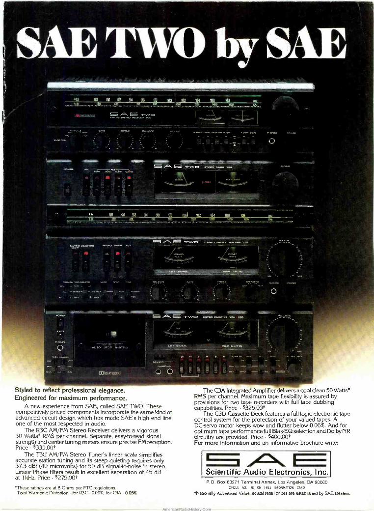
,..°m . '. -aP _. , e . " . o_ .1"4itt_
=M 88 90 91 94 98 98 DO , 102 104 108 108 w
13111f^ T{1 = A tarAnut mo
.... ..g. a.c
I `
o T
4t919% ium «- =----".-- - - - ---- -'---- - - _ ` .-__- F=°....r.'
^ _. ` . _
. . 1 9cV+t
FM QB 90 92 94 98 98 1091 102 114 108 108 M A M Bd0 , ,i, moo -^ ... .. -
- - . - _ .o,.... - .w 11F._+'__-....._. .._.-. _ _
IACCC 'OW
}+YiAt1 r 111
AUTO STOP SYSTEM
OCOMI
r f -1\C TWO srureo ourrace_ cua. .
!(!
Ío ,i
1
_9 ws.+ eww`r
TWO n..o caxTn ocrx am
uí, ocAaut.
ettuo
O O =
Styled to reflect professional elegance. Engineered for maximum performance.
A new experience from SAE, called SAE TWO. These competitively priced components incorporate the same kind of advanced circuit design which has made SAE's high end line one of the most respected in audio.
The R3C AM/FM Stereo Receiver delivers a vigorous 30 Watts* RMS per channel. Separate, easy -to -read signal strength and center tuning meters ensure precise FM reception. Price - $335.00t
The T3U AM/FM Stereo Tuner's linear scale simplifies accurate station tuning and its steep quieting requires only 37.3 dBf (40 microvolts) for 50 dB signal-to-noise in stereo. Linear Phase filters result in excellent separation of 45 d3 at 1 kHz. Price $275.00t
MN-
%g-
MG Level.
- w . 1:20.0,'. w me MI.AKJ
The C3A Integrated Amplifier delivers a cool clean 50 Watts* RMS per channel. Maximum tape flexibility is assured by provisions for two tape recorders with full tape dubbing capabilities. Price - $325.00t
The C3D Cassette Deck features a full -logic electronic tape control system for the protection of your valued tapes. A DC -servo motor keeps wow and flutter below 0.06%. And for optimum tape performance full Bias-EQ selection and Dolby NR circuitry are provided. Price - $400.00t For more information and an informative brochure write:
Scientific Audio Electronics, Inc.
'These ratings are at 8 Ohms per FTC regulations. Total Harmonic Distortion - for R3C 0.09%, for C3A - 0.05%
P.O. Box 60271 Terminal Annex, Los Angeles, CA 90060 CIRCLE NO. 48 ON FREE INFORMATION CARD
tNationally Advertised Value, actual retail prices are established by SAE Dealers.
AmericanRadioHistory.Com

Performance that's easy to handle. The Motorola® Sys -
tern 500 Remote CB. The first full -featured Remote (r°111,41,
that's easy to handle. It's designed to feel natural. To operate effortlessly. 4o``
bead With about as much thought as you give to shifting gears.
But what good is a Remote that fits your hand, if it doesn't fit your needs? The Motorola System 500 Remote features a 2 -speed channel selector. A local/distance switch that reduces inter- ference and background noise. A channel 9 emergency switch that puts you in touch with help instantly when you need it.
' °.. ' . ° °, °, °°,-
i
You also get the CB features you've come to expect from Motorola. Like a phase lock -loop synthesizer. Power mic. Phosphorescent control labels for easy identification. Hot -last channel memory. L.E.D. channel readout. And an optional relay which interrupts radio audio as CB messages are received.
As easy as it is to handle and operate, this CB is tough to steal. The transceiver chassis is compact- easily hidden away in the trunk, under the seat, or mounted on the firewall.
The complete, uncomplicated Motorola System 500 Remote. Because when you're driving, you've got enough to handle.
MOTOROLA CB CIRCLE NO. 52 ON FREE INFORMATION CARD
To find the dealer nearest you, wiite: Market Relations Manager. Motorola, Inc., Automotive Products Division, 1299 East Algonquin Road, Schaumburg, Illinois 60196. Motorola is a registered trademark of Motorola Inc.
AmericanRadioHistory.Com
![· -Manual Tuning -Direct keypad Entry ... TECSUN kHz SYNC USB — PAGE ± FM SW DETECTOR ... PL-660. pow FM] AM] SW VOLUM flashin](https://img.dokumen.tips/doc/110x75/5beae02909d3f2ff498c2863/-manual-tuning-direct-keypad-entry-tecsun-khz-sync-usb-page-fm-sw.jpg)