Embed Size (px)
Citation preview
Housing Earthquake Safety Initiative (HESI)
Building Earthquake Resistant Houses Safer Non-Engineered Construction for All Training Workshop for Engineers Construction of Earthquake Resistance Buildings, Banda Aceh, Oct. 2008
Edited by: Jishnu Kumar Subedi (UNCRD Disaster Management Hyogo Office) Hari Darshan Shrestha (Save the Children, Jakarta Office)
2009
UNCRD

© 2009 United Nations Mission Statement of UN/DESA The Department of Economic and Social Affairs of the United Nations Secretariat is a vital interface between global policies in the economic, social and environmental spheres and national action. The Department works in three main interlinked areas: (a) it compiles, generates and analyses a wide range of economic, social and environmental data and information on which State Members of the United Nations draw to review common problems and to take stock of policy options; (b) it facilitates the negotiations of Member States in many intergovernmental bodies on joint courses of action to address ongoing or emerging global challenges; and (c) it advises interested Governments on the ways and means of translating policy frameworks developed in United Nations conferences and summits into programmes at the country level and, through technical assistance, helps built national capacities. Save the Children is the leading independent organization creating real and lasting change for children in need in the United States and around the world. It is a member of the International Save the Children Alliance, comprising 28 national Save the Children organizations working in more than 110 countries to ensure the well-being of children. Vision A world in which every child is ensured the right to survival, protection, development and participation as set forth in the United Nations Convention on Right of Child. Mission To create lasting, positive change in the lives of children in need Designations employed and presentation of material in this publication do not imply the expression of any opinion whatever on the part of the United Nations Secretariat or the United Nations Centre for Regional Development, concerning the legal status of any country or territory, city or area, or of its authorities, or concerning the delimitation of its frontiers or boundaries.
Earthquake claims thousands of lives and millions of dollars every year. Majority of these losses are caused by collapse of houses and buildings. The experiences show that building constructed with earthquake resistant technology can reduce the losses significantly. There already exists the scientific knowledge on earthquake resistant buildings and many earthquake prone countries have already established earthquake resistant building code, however effective implementation has been a major challenge. Major reasons for the knowledge not being translated into action are: lack of awareness among experts and communities, lack of institutional mechanism for monitoring and insufficient capacity of implementing authorities, and lack of easily understandable manuals for community people. The United Nations Centre for Regional Development (UNCRD) held an expert meeting on the anti-seismic building code dissemination (ABCD) and initiated the Housing Earthquake Safety Initiative (HESI) in January 2007. HESI is conducting a series of activities in three target countries: Nepal, Peru, and Indonesia. The part I “Materials for the Workshop in Aceh 2008: Constructing Earthquake Resistant Buildings” of this publication is a record of the training workshop delivered for engineers organised by Save the Children and UNCRD. The workshop aimed to provide practical knowledge on construction of earthquake resistant buildings, and by combining field works it became a good opportunity for engineers to see the problem faced in the construction field in Aceh. Although the documents enclosed here are based upon experiences in Indonesia, the most seismic-prone country in the world, we believe that it could be a useful tip for other countries facing similar challenges as well as for organisations working on capacity building of local authorities to implement to safer building effectively. Also, the team hope that this could be one of the milestones on the work towards securing safer construction in Indonesia whilst the efforts for developing and spreading on non-engineered housing construction in every stakeholder are still underway. Lastly, please be noted that the Indonesian Building Code in this document is quoted as of 2008. UNCRD Disaster Management Planning Hyogo Office- Editorial Team Kobe-city, Hyogo, Japan, May 2009
Preface
i
Chapter 1 Background and Introduction 2
Chapter 2 Opening Session and Course Introduction 4
Chapter 3 Introduction to Indonesian Building Code 7
Chapter 4 Issues in Construction Sites 15
Chapter 5 On-site Observation 22
Chapter 6 Lessons and Evaluation of Existing Construction Practices 26
Chapter 7 Vulnerability Assessment and Retrofitting 31
Chapter 8 Conclusion and the Way Forward for Disaster Risk Reduction 44
Annex Programme of Training Workshop 50
Table of Contents
ii
Materials of the Training Workshop for Engineers in Aceh 2008
Constructing Earthquake Resistant Buildings
Background Urbanization process is increasing rapidly in most of the countries in Asia, Indonesia is one where the population living in urban areas is increasing rapidly and also the potential villages with economic opportunity are in process of urbanization. It is estimated that more than half of the world's human population will be living in towns and cities by 2008. One of the major challenges for these urban areas is to provide safe structure for the growing population. Along with the increase of population, every year numbers of school buildings along with other infrastructure are in construction. In earthquake prone countries it's more challenging, as collapse of houses and buildings is the major reason for the loss of lives and property, recent China earthquake is the evident. Along with other people thousands of school children were killed due to collapse of school buildings and houses built with substandard material, workmanship and without consideration of codal provisions in China earthquake. The experiences from past and even from recent earthquakes show that building constructed with earthquake resistant technology can reduce the losses significantly. There already exists a scientific know-how on earthquake resistant buildings and the state-of-art knowledge is well documented in the form of building codes. However, many earthquake prone countries are still struggling for effective implementation of building code. Effective enforcement of earthquake resistant building codes and control system can reduce the loss significantly. One of the major challenges in effective implementation of building code is problem in translating the knowledge into real practice. Some of the reasons for the knowledge not being translated into action are: lack of awareness, lack of institutional mechanism for implementation and insufficient capacity of implementing authorities. Indonesia established building code
in 1981 and enacted in 1989. The code was updated again in 2002. Despite of this long history of establishment of building code and history of frequent large scale earthquakes, the large share of construction practices do not comply with the provisions of building code. Construction scenario in Aceh As in other part of world, urbanization trend is rapidly growing in Aceh Province of Indonesia and building typology, constructional material and construction technology is in transitional phase, is moving from traditional to the modern. Past experience shows that the buildings/houses constructed with traditional construction technology and material stands after earthquake and more or less no loss of life, are more earthquake resistant. But due to urbanization process, adaptation of new technology and material in construction of buildings without engineering input and codal practice may change the scenario and loss may dramatically increase in the event of earthquake in future. There is a need of awareness on people and also enforcement on implementation of building Code to reduce the magnitude of disaster in future. Against this background, a Training Workshop on "Construction of Earthquake Resistant Buildings: From Code to Practice" was organized on October 13 - 16, 2008 in Banda Aceh, Indonesia jointly by Save the Children, Aceh Program and UNCRD. The main objective of the training program was to provide participants practical knowledge on construction of earthquake resistant buildings in compliance with codal and other proven practice. After completion of the training, the participants will be able to: Understand the major provisions of building construction in seismic codes • Understand the good practices in planning and material selection • Carry out simple material testing and vulnerability checking
Chapter 1
Background and Introduction
2

• Know how on retrofitting technique and importance • Detail out key elements of earthquake resistant buildings • Identify vulnerable components and approach to increase their safety The training was joined by technical persons from municipalities, NGO’s, consultant, government bodies responsible for building construction and supervision and others involved in construction of buildings. Modality of the training The training was conducted as interactive learning training. Participants had been provided with experience and advise of resource persons as initial input. Easy to understand figures, physical models and photographs from actual construction sites has been the essential feature of this training program. The participants then were invited to draw their own experience and detail out real challenges they face in the field. The participants were asked to work in group to sort out the problems they raise and come up with the best solution. At the middle of the
training a field visit was organized where participants detail out the problems and good practices which was shared in the group discussion. The final outcome of the training workshop was a framework for quality construction in the field with necessary check-list, testing methods, forms and procedures. Course Outline and Modules The training course has 8 modules including opening and closing sessions. Module 0: Opening session and introduction of the course Module 1: Introduction to Indonesian Building Code Module 2: Implementation of the code: Issues in construction sites Module 3: On-site observation of field practices Module 4: Lessons and evaluation of existing construction practices Module 5: Assessment of existing buildings and element strengthening techniques Module 6: The way forward: Practical approach for quality construction Module 7: Evaluation and closing Detail training program is given in Annex I.
3

Objective The module is introductory module and has two specific purposes:
1. To introduce the course objectives to local stakeholders 2. To provide orientation to the participants regarding the training program
The introductory session is also an opportunity to raise awareness among communities. Expected outcome The module is formal opening session for the training. After this module, the participants become aware of the content of the training program and set ground rules by themselves for optimum result from the training. Module outline Participants' Registration Formal Opening Session Seating of invited dignitaries and participants Welcome address Opening remarks by the Chief Guest Address and Brief Introduction of the training Address by representatives BRR Group Photo and Break Objectives and introduction of the modules Introduction of the participants Training modality and ground rules Group division
Time Two hrs.
Chapter 2
Opening Session and Course Introduction
4

Objectives and introduction of the modules Contributed by: Jishnu Subedi Introduction to Housing Earthquake Safety Initiative of United Nations Centre for Regional Development
Background - Collapse of buildings: One of the major causes for casualties in earthquakes - Effective implementation of building code can prevent the damages and causalities - Most of the earthquake prone countries have building codes - Problem in implementation
Introduction to Housing Earthquake Safety Initiative of United Nations Centre for Regional Development Key activities - United Nations Centre for Regional Development is one of the pioneers in disaster management - HESI project was started in 2007 with support of Government of Japan
- Four activities: System Evaluation; Awareness Raising; Policy Development; Capacity Development Introduction to Housing Earthquake Safety Initiative of United Nations Centre for Regional Development Objectives Activities Outputs Title and main objective of the training workshop - Construction of Earthquake Resistant Buildings: From Code to Practice - Four days Training
- Main objective: To provide participants practical knowledge on construction and retrofitting of earthquake resistant buildings After completion of the training, the participants are expected to achieve the six objectives - Understand the major provisions of building construction in seismic codes - Understand the good practices in planning and material selection - Carry out simple material testing and vulnerability checking - Know how on retrofitting technique and importance - Detail out key elements of earthquake resistant buildings - Identify vulnerable components and approach to increase their safety
To raise awareness
To develop capacity of national and local government officials
To develop policy recommendations
To raise awareness
To develop capacity of national and local government officials
To develop policy recommendations
Awareness raising workshops/ Programs/ Documents
Trainings/ Workshops
Experts meeting/ policy recommendations
Awareness raising workshops/ Programs/ Documents
Trainings/ Workshops
Experts meeting/ policy recommendations
Objectives Activities Outputs
Trainings: Nepal, Peru, Indonesia
Publications
Good practice booklet
Handbook
Policy Recommendations
Trainings: Nepal, Peru, Indonesia
Publications
Good practice booklet
Handbook
Policy Recommendations
5
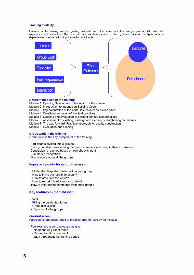
Training modality Lectures in the training are just guiding materials and other major activities are group-work, field visit, field experience and interaction. The final outcome, as demonstrated in the right-hand side of the figure is more dependent on the interaction/input from the participants. Different modules of the training Module 1: Opening Session and introduction of the course Module 2: Introduction to Indonesian Building Code Module 3: Implementation of the code: Issues in construction sites Module 4: On-site observation of the field practices Module 5: Lessons and evaluation of existing construction practices Module 6: Assessment of existing buildings and element strengthening techniques Module 7: The way forward: Practical approach for quality construction Module 8: Evaluation and Closing Group work in the training Group work is the key component of the training Participants divided into 5 groups Each group discusses among the group members and bring in their experience Conclusion is reached based on everybody’s input Summary presentation Discussion among all the groups
Important points for group discussion - Moderator/ Reporter: Select within your group - How to invite everybody to speak? - How to articulate the views? - How to report it briefly and accurately?
- How to incorporate comments from other groups Key features in the field visit - Visit - Filling the distributed forms - Group discussion - Reporting to the groups
Ground rules Participants are encouraged to propose ground rules by themselves Few example ground rules are as given - No phone ring-silent mode - Raising hand for comment - Stay throughout the training period
6
Group work
Lectures
Field experience
Field visit
Interaction
Group work
Lectures
Field experience
Field visit
Interaction
Final Outcome
Lectures
Participants
Lectures
Participants
Lectures
Participants
Lectures
Participants
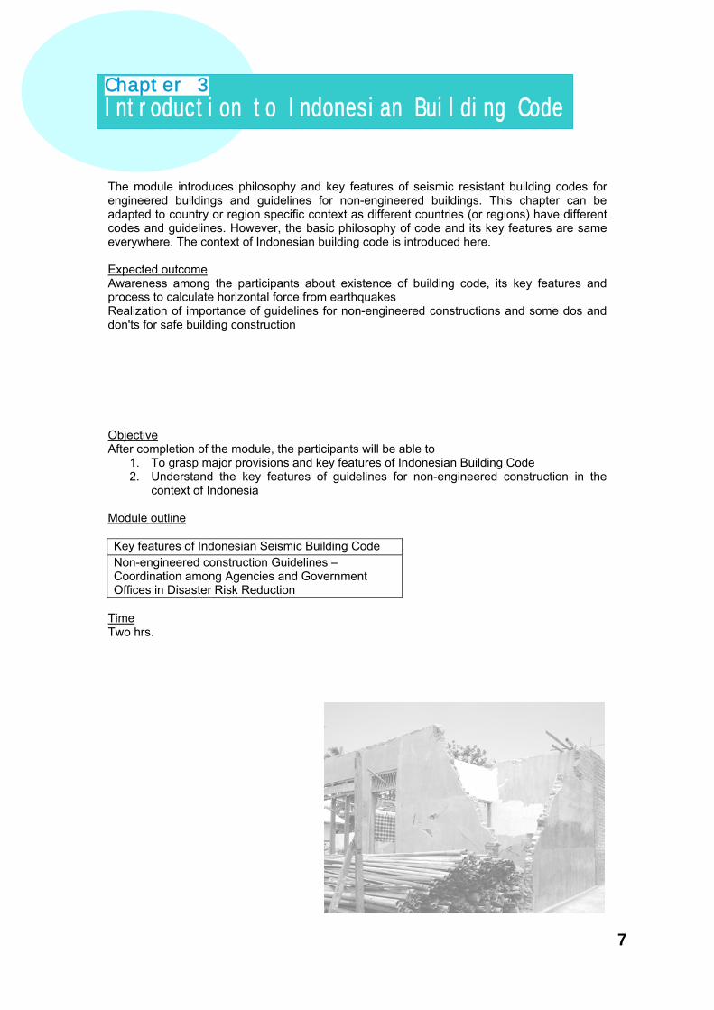
The module introduces philosophy and key features of seismic resistant building codes for engineered buildings and guidelines for non-engineered buildings. This chapter can be adapted to country or region specific context as different countries (or regions) have different codes and guidelines. However, the basic philosophy of code and its key features are same everywhere. The context of Indonesian building code is introduced here. Expected outcome Awareness among the participants about existence of building code, its key features and process to calculate horizontal force from earthquakes Realization of importance of guidelines for non-engineered constructions and some dos and don'ts for safe building construction Objective After completion of the module, the participants will be able to
1. To grasp major provisions and key features of Indonesian Building Code 2. Understand the key features of guidelines for non-engineered construction in the
context of Indonesia Module outline Key features of Indonesian Seismic Building Code Non-engineered construction Guidelines –Coordination among Agencies and Government Offices in Disaster Risk Reduction
Time Two hrs.
Chapter 3
Introduction to Indonesian Building Code
7

Introduction to Indonesian Building Code Contributed by: Yuskar Lase Building's life cycle phase Structural Building Code Structural Building Code Indonesian structural building code Loading Code - Pedoman Perencanaan Pembebanan untuk Rumah dan Gedung (SKBI 1.3.53.1987. Departamen Pekerjaan Umum) Concrete Code - Tata Cara Perecanaan Struktur Beton untuk Bangunan Gedung (SNI 03-2847-2002. Badan Standardisasi Nasional) Steel Code - Tata Cara Perencanaan Structur Baja untuk Bangunan Gedung (SNI 03-1729-2002. Badan Standardisasi Nasional) Wood Code - Tata Cara Perencanaan Struktur Kayu untuk Bangunan Gedung (RSNI. Badan Standardisasi Nasional) Seismic Code - Tata Cara Perencanaan Ketahanan Gempa untuk Bangunan Gedung (SNI 03-1726-2002. Badan Standardisasi Nasional) Why Seismic Building Code?
BuildingCode
BuildingCode
BuildingCode
Structural Building Codes :
• Loading Code
• Concrete Code
• Steel Code
• Wood Code
• Seismic Code
8
Architectural Design
Architectural Design
Architectural Design
Mechanical/Electrical Design
Mechanical/Electrical Design
Mechanical/Electrical Design
Detail Engineering
Design
Detail Engineering
Design
Structural Design
Structural Design
Earthquake
Exact force to building?
Building Seismic Resistance
• Cost of Construction• Economic Viability :- Safe of final product- Cost Efficiency
Type of lateral load –resisting system
• Size and characteristics of earthquake• Distance from fault• Site Geology
Components in Indonesian Building Code Indonesian Seismic Building Code - Code Philosophy - Design and Detailing Structural Components - Design Earthquake - Design Limitations - Structural Analysis - Design Requirements - Design Base Share Code Philosophy Level of protection:
1. Serviceability limit state Under minor earthquake, no damage that needs to be repaired should occur to the structure or to the non-structural components
2. Damage control limit state Under medium earthquake, some damage may occur to the structure but it is still economically repairable.
3. Survival Limit State Under large earthquake, extensive damage may occur to the structure and may be unrepairable, but collapse must not occur. Life safety must be insured.
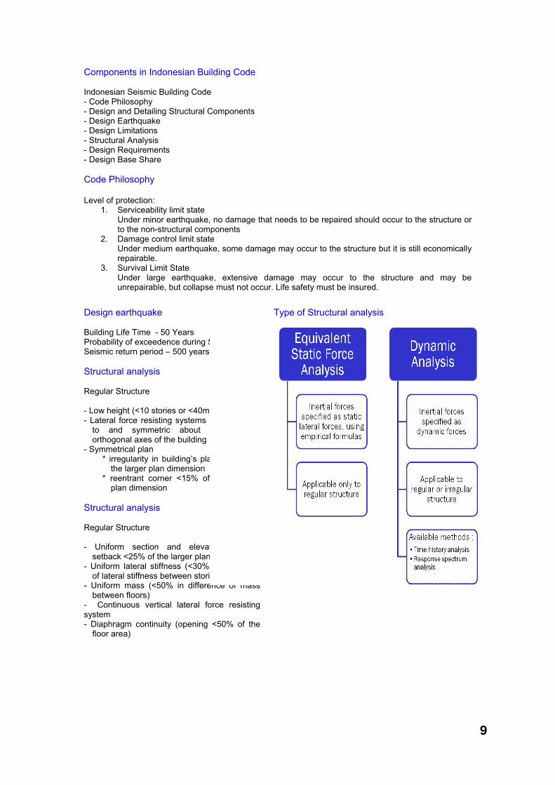
Design earthquake Type of Structural analysis Building Life Time - 50 Years Probability of exceedence during 50 years – 10 % Seismic return period – 500 years Structural analysis Regular Structure - Low height (<10 stories or <40m in height) - Lateral force resisting systems are parallel
to and symmetric about the major orthogonal axes of the building
- Symmetrical plan * irregularity in building’s plan <25% of
the larger plan dimension * reentrant corner <15% of the larger
plan dimension Structural analysis Regular Structure - Uniform section and elevation (vertical
setback <25% of the larger plan dimension) - Uniform lateral stiffness (<30% in difference
of lateral stiffness between stories) - Uniform mass (<50% in difference of mass
between floors) - Continuous vertical lateral force resisting system - Diaphragm continuity (opening <50% of the
floor area)
9

1. Design base shear (V) Where, Wt = Gravity load (dead load + application portion of live load), C = Seismic coefficient I = Occupancy importance factor R = Reduction factor of structural system 2. Seismic Coefficient (C) - 6 seismic zones - 3 soil types (soft, medium, and stiff soils) - Fundamental period of the structure (Tn), determined by exact method or empirical formula Design base shear (V) Seismic Zone Map Indonesian Seismic Zone Map Design base shear (V) Response Spectrum Elastic Design Response Spectrum
Design base shear (V) Soil type Design base shear (V)
Soil type
Soil description
Weighted average soil properties for top 30m of soil profile
Shear wave velocity, vs
(m/sec)SPT, N
Undrained shear strength, Su
(kPa)
Stiff soil ≥350 ≥50 ≥100
Medium soil 175 to 350 15 to 50 50 to 100
Soft soil
<175 <15 <50
It also includes any soft soil profile with more than 3m thick of soft soil with PI>20, wn>40%, and Su < 25kPa
10

Design base shear (V) 3. Occupancy Important Factor (I) Occupancy Importance Factor (I) - Correction factor on return period due to the probability of seismic exceedance (I1) - Correction factor on return period due to the building life time (I2)
Design base shear (V) Occupancy Important Factor (I) Design Base Shear (V) 4. Seismic Reduction Factor (R) - Ductility Factor - Structural System Design base shear (V) Ductility Factor
Building CategoryOccupancy Importance Factor
I1 I2 IOccupancy Structures
(apartments, office buildings, etc.) 1.0 1.0 1.0
Special Structures(monuments, museums, etc.) 1.0 1.6 1.6
Essential Facilities(hospital, fire station, power plant,
aviation control towers, etc.)1.4 1.0 1.4
Hazardous Facilities(housing of toxic/chemical/explosive
chemical or substances)1.6 1.0 1.6
Miscellaneous Structures(towers, chimney, etc.) 1.5 1.0 1.5
Basic Structural
System
Lateral force Resisting System Description μm Rm f
Bearing Wall System
1. Shear walls 2.7 4.5 2.82. Light steel-framed bearing walls with
tension-only bracing 1.8 2.8 2.2
3. Braced frames where bracing carries gravity load
a. Steel 2.8 4.4 2.2b. Concrete 1.8 2.8 2.2
Basic Structural
System
Lateral force Resisting System Description μm Rm f
Bearing Wall System
1. Shear walls 2.7 4.5 2.82. Light steel-framed bearing walls with
tension-only bracing 1.8 2.8 2.2
3. Braced frames where bracing carries gravity load
a. Steel 2.8 4.4 2.2b. Concrete 1.8 2.8 2.2
Basic Structural
System
Lateral force Resisting System Description μm Rm f
Building Frame System
1. Steel Eccentrically Braced Frame (EBF) 4.3 7.0 2.8
2. Shear walls 3.3 5.5 2.83. Ordinary braced frames
a. Steel 3.6 5.6 2.2b. Concrete (zone 5 and 6 excluded) 3.6 5.6 2.2
4. Special concentrically braced frames (steel) 4.1 6.4 2.2
5. Ductile framed shear wall 4.0 6.5 2.86. Full ductile cantilevered shear wall 3.6 6.0 2.87. Partial ductile cantilevered shear wall 3.3 5.5 2.8
11

Design base shear (V) Ductility Factor
Basic Structural
System
Lateral force Resisting System Description μm Rm f
Moment Resisting
Frame System
1. Special Moment Resisting Frame (SMRF)
a. Steel 5.2 8.5 2.8b. Concrete 5.2 8.5 2.8
2. Concrete Intermediate Moment Resisting Frame (IMRF) 3.3 5.5 2.8
3. Ordinary Moment Resisting Frame (OMRF)
a. Steel 2.7 4.5 2.8b. Concrete 2.1 3.5 2.8
4. Special Truss Moment Frames (STMF) of steel 4.0 6.5 2.8
Basic Structural
System
Lateral force Resisting System Description μm Rm f
Dual Systems
1. Shear walls
a. Concrete with concrete SMRF 5.2 8.5 2.8b. Concrete with steel OMRF 2.6 4.2 2.8c. Concrete with IMRF 4.0 6.5 2.8
2. Steel EBFa. With steel SMRF 5.2 8.5 2.8
b. With steel OMRF 2.6 4.2 2.83. Ordinary Braced Frame
a. Steel with steel SMRF 4.0 6.5 2.8b. Steel with steel OMRF 2.6 4.2 2.8
Basic Structural
System
Lateral force Resisting System Description μm Rm f
Dual Systems
c. Concrete with concrete SMRF (zone 5 and 6 excluded) 4.0 6.5 2.8
d. Concrete with concrete IMRF (zone 5 and 6 excluded) 2.6 4.2 2.8
4. Special concentrically braced framesa. Steel with steel SMRF 4.6 7.5 2.8b. Steel with steel OMRF 2.6 4.2 2.8
Cantilevered Column Building Systems
Cantilevered column elements 1.4 2.2 2.0
Basic Structural
System
Lateral force Resisting System Description μm Rm f
Shear Wall –Frame
Interaction Systems
Concrete (zone 3, 4, 5, and 6 excluded) 3.4 5.5 2.8
Single Sub-system
1. Open steel frame 5.2 8.5 2.82. Open concrete frame 5.2 8.5 2.83. Open concrete frame with pre-stress 3.3 5.5 2.84. Full ductile framed concrete 4.0 6.5 2.85. Partial ductile framed concrete 3.3 5.5 2.8
12

Design base shear (V) Lateral force Distribution (Fi) 5. Distribution of Lateral Force (Fi) For equivalent static force method
Where: Wi = Gravity load at level i Zi = Height in m, above the base to level i Ft = Additional lateral force at the top level
Design requirements P- Delta effect Consider : 1: P-delta effect :
for buildings with more than 10 stories or 40 m in height
2. 2 orthogonal earthquakes EQx = earthquake in x direction EQy = earthquake in y direction 3: Design eccentricity for 0 < e ≤ 0.3 b : ed = 1.5 e + 0.05 b or ed = e – 0.05 b for e > 0.3 b : ed = 1.33 e + 0.1 b or ed = 1.17 e – 0.1 b
Design requirements Equivalent Reduction Factor (R) Consider: 4: Equivalent seismic reduction factor ( R ) Where: Rx = Seismic reduction factor in x direction Vxo = Base shear in x direction Ry = Seismic reduction factor in y direction Vyo = Base shear in y direction
Design limitations Fundamental period 1. Empirical formula limitation for estimating fundamental period
Raileigh formula
Design limitations Fundamental period 2. Dynamic analysis limitation : - Effective mass participation factor ≥ 90% - Dynamic base shear ≥ 80% static base shear
3. Fundamental period limitation : T £ z x n n = number of floor
ζ=
Design limitations Drift (D) 4. Drift limitation : - Serviceability performance
- Ultimate performance 0.7 x R x D £ 0.02’ floor height
5. Dilatation between 2 buildings (δ): d3 0.025’ building height (>75mm) 3 total drift of 2 buildings
o o
x y
o o
x x y y
V VR
V R V R
+=
+%20%100x
TTT
r
r ≤−
Seismic zone ζ Seismic zone ζ1 0.2 4 0.172 0.19 5 0.163 0.18 6 0.15
Seismic zone ζ Seismic zone ζ1 0.2 4 0.172 0.19 5 0.163 0.18 6 0.15
∑
∑
=
== n
1iii
n
1i
2ii
r
xdVg
xdW3.6T
30% EQ y
100% EQ x
100% EQ y
30% EQ x
13
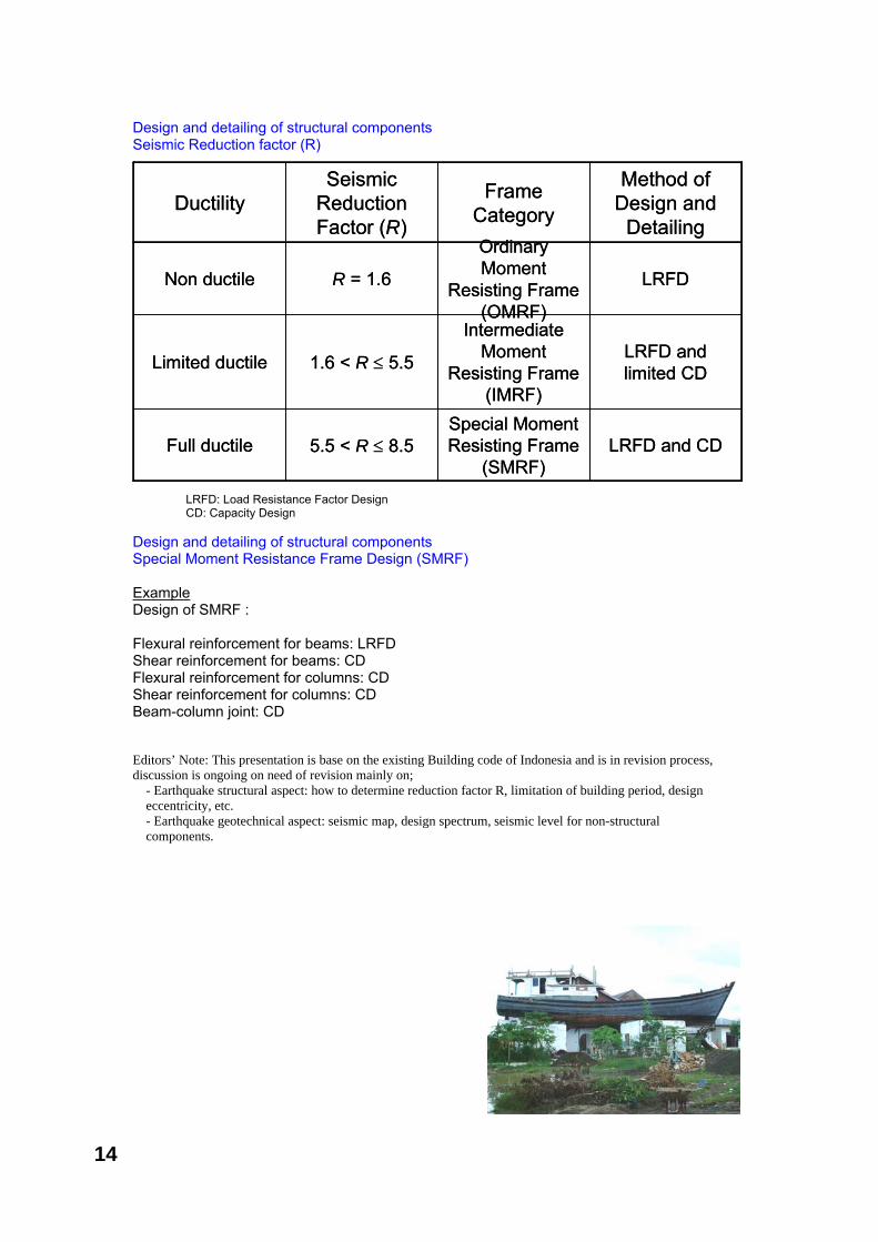
Design and detailing of structural components Seismic Reduction factor (R)
LRFD: Load Resistance Factor Design CD: Capacity Design Design and detailing of structural components Special Moment Resistance Frame Design (SMRF) Example Design of SMRF : Flexural reinforcement for beams: LRFD Shear reinforcement for beams: CD Flexural reinforcement for columns: CD Shear reinforcement for columns: CD Beam-column joint: CD Editors’ Note: This presentation is base on the existing Building code of Indonesia and is in revision process, discussion is ongoing on need of revision mainly on;
- Earthquake structural aspect: how to determine reduction factor R, limitation of building period, design eccentricity, etc. - Earthquake geotechnical aspect: seismic map, design spectrum, seismic level for non-structural components.
DuctilitySeismic
Reduction Factor (R)
Frame Category
Method of Design and
Detailing
Non ductile R = 1.6
Ordinary Moment
Resisting Frame (OMRF)
LRFD
Limited ductile 1.6 < R ≤ 5.5
Intermediate Moment
Resisting Frame (IMRF)
LRFD and limited CD
Full ductile 5.5 < R ≤ 8.5Special Moment Resisting Frame
(SMRF)LRFD and CD
14
There is enough knowledge base for earthquake safe building constructions which has been well documented in codes and guidelines. Despite of the existing know-how and technology, the building constructed in the field do not meet the criteria of safe buildings. The module introduces the issues in construction practices and implementation of the code in the context of Indonesia in general and Aceh, in particular. This chapter can be adapted to country or region specific context as different countries (or regions) have different issues in implementation. However, the basic issues are similar: non-symmetrical construction for non-engineered buildings; wide variation in design and construction; poor workmanship; poor quality materials and selection of inappropriate site. The context and experience of construction in Aceh is introduced here. Objective After completion of the module, the participants will be able:
1. To understand the gap between design and construction
2. To identify critical issues in the real construction sites
3. To understand the importance of field testing of material and apply few simple field quality testing methodologies
Expected outcome Real scenario of the issues in construction sites and challenges in building code implementation Simple field testing methodology for quality control Module outline Problems in real construction sites (Pictures, slides and video compilation of poor construction practices) Group work Group discussion on poor practices in construction Group presentation Material tests and quality control in the fields Good detailing practices
Time Five hrs. The participant will discuss for 1 hr. in group about the real issues in construction sites and each group will make a presentation of about 5-7 minutes.
Three Important Issues on Aceh Future Earthquake Resilience Building Construction Which Need to be Anticipated Contributed by: Hari Darshan Shrestha and Arwin Soelaksono Scenario, Challenges and Need The demand of multi-stories buildings and their development trends are far beyond the capabilities and common practices of the builders
Building local capacity in overall construction activities – from design to construction and maintenance
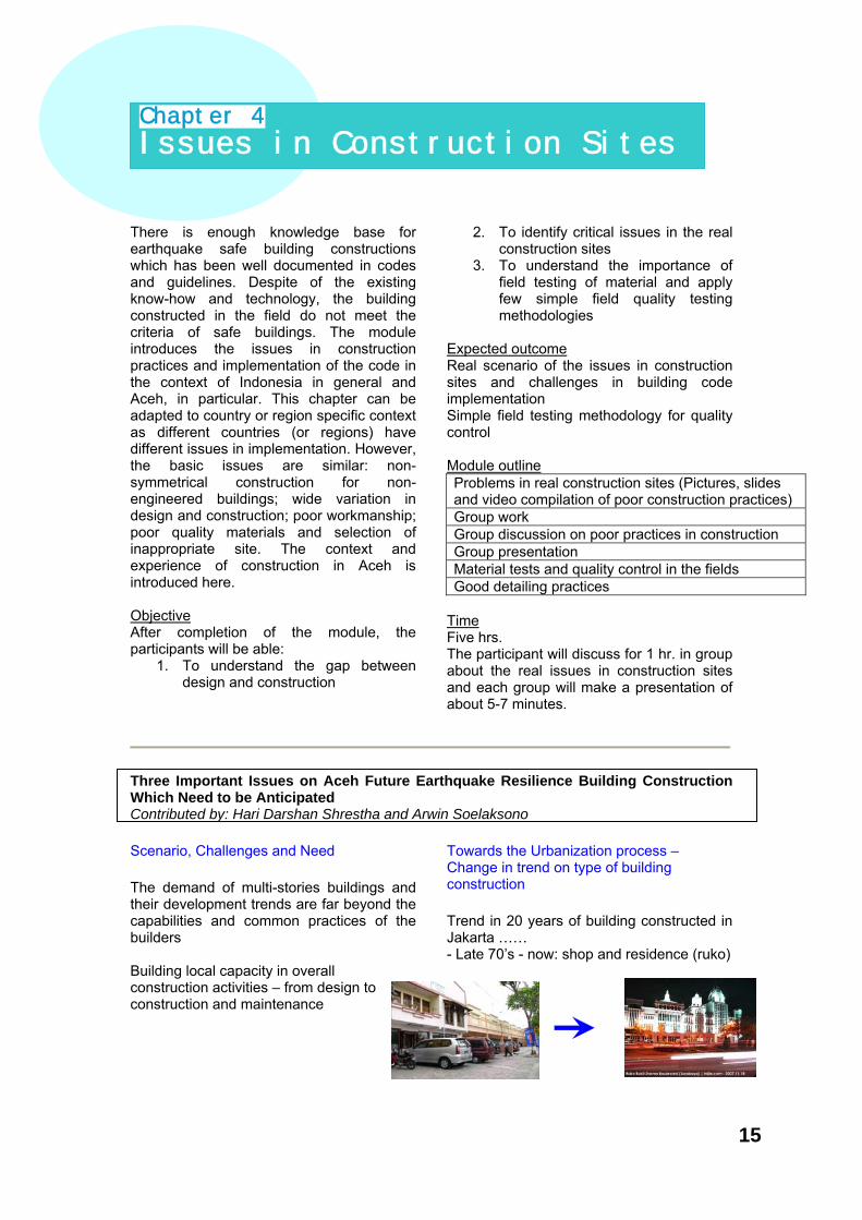
Towards the Urbanization process – Change in trend on type of building construction Trend in 20 years of building constructed in Jakarta …… - Late 70’s - now: shop and residence (ruko)
Chapter 4
Issues in Construction Sites
15

Towards the Urbanization process – change in trend on type of building construction Urbanization Process Is ongoing on all other Cities of Indonesia Trend in 20 years of building constructed in Jakarta …… - 90’s - now: shopping mall and condominium
Banda Aceh - towards the Urbanization process, Trend changed, multy storey buildings are coming up
Meulaboh, Aceh - towards the Urbanization process Trend changed, multy storey buildings are coming up
Three main key areas to ensure the construction of safe buildings
Design and Planning Scenario and recommendation
Common design practices are tend to produce soft-stories structure especially in Ruko structures
Non symmetrical and non uniform structure need to thoroughly designed and the builder should ensure their capacity
Design and Planning Recommendations Every building is subjected to follow the nature law of earthquake force. Therefore every design recommended to:
Avoid soft story structure
Building should be in simple form and rectangular otherwise thoroughly engineering design should be done in respect to various dynamic earthquake load calculation
In a crowd building area/compound, a gap to the next building should be considered based on the time response of the building and the next building adjacent to it.
House at Meulaboh
Design and planning
Building permit and regulation
Capacity of constructor
16

Avoid - the area potential to liquefaction Settlement of building due to Liquefaction...Sept 12, 2007 Bengkulu, Sumatra
Building permit and regulation Recommendations Due to increase of the demand on ruko or other multi-stories building regardless the land has potential risk of liquefaction, the regulator recommended to: A: Comprehensive soil investigation should be completed prior the building permit issuance. B: Every developer / ruko owner should be discourage on building in liquefaction prone soil.
Need of proper detailing and follow the guidelines and codal provision
Field engineers and supervisors overlook on detailing
- splice length and hook on stirrups - beam-column connection etc.
leads to brittle failure on major structural element such columns and joints with beams which cause to catastrophic failure.
Proper material – selection and testing
Quality control on material use in construction - handling and storing - mixing - testing Not proper on those mention above leads to deteriorate the quality of structure and will not achieve designed specification
Field test to determine strengths and quality of materials Important test should be carried out in the field: - Slump test - Water quality testing - Schmidt hammer testing (for some condition)
Need of proper fixing of non structural elements
Imperfect finishing work endanger the inhabitant during the earthquake - falling of ceiling - parapet fall apart
Scenario on Capacity of constructors and recommendations Every constructor should realize their responsibility to produce safe structure to comply the design and specification. Therefore every constructor recommended to: A. Enhance inner capacity of human resource and policy procedure and protocol of operations. B. Invest in equipment to produce good quality workmanship. It is urgent for the engineering designer, government / regulator and the building contractor to enhance their capacity to anticipate on more complex and higher demand on building to be constructed in this earthquake prone area.
September 12, 2007, Bengkulu, Sumatera
… liquefaction …
17
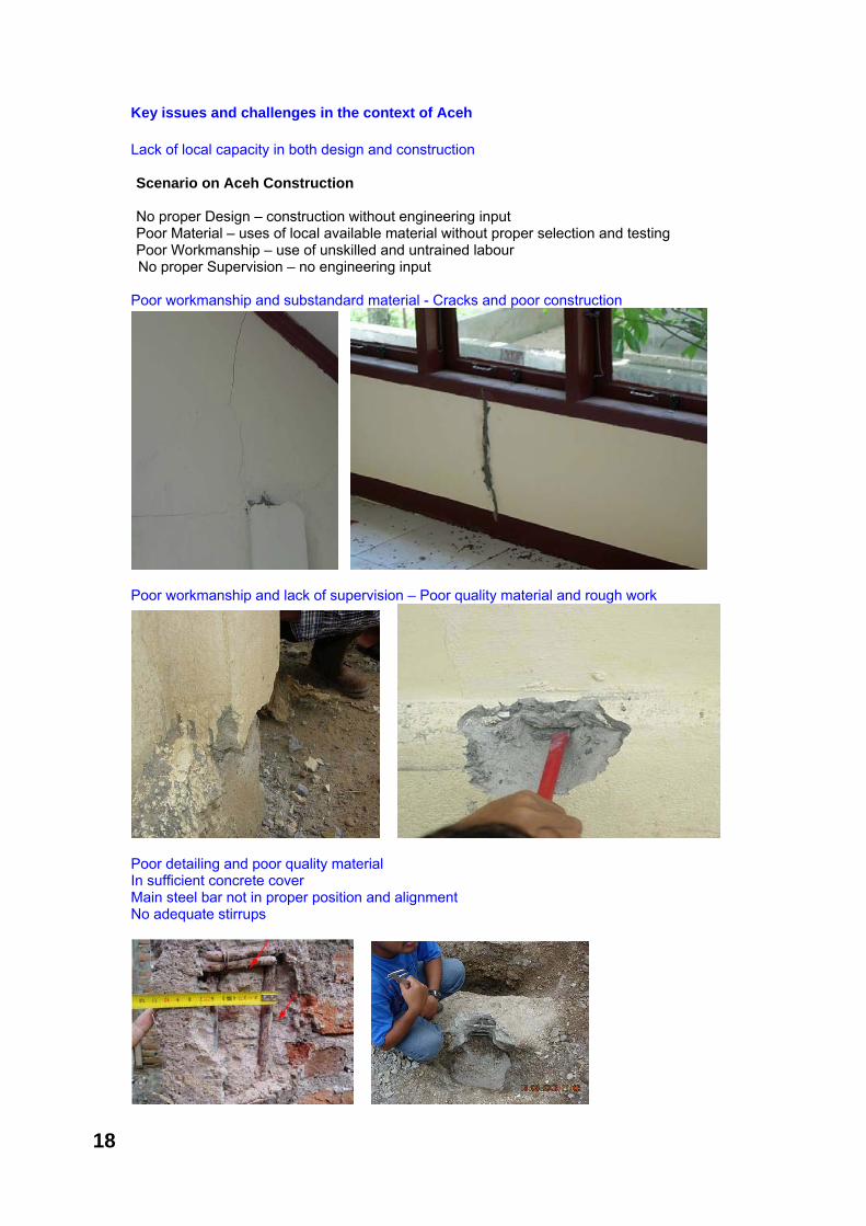
Key issues and challenges in the context of Aceh Lack of local capacity in both design and construction Scenario on Aceh Construction No proper Design – construction without engineering input Poor Material – uses of local available material without proper selection and testing Poor Workmanship – use of unskilled and untrained labour No proper Supervision – no engineering input
Poor workmanship and substandard material - Cracks and poor construction
Poor workmanship and lack of supervision – Poor quality material and rough work
Poor detailing and poor quality material In sufficient concrete cover Main steel bar not in proper position and alignment No adequate stirrups
18
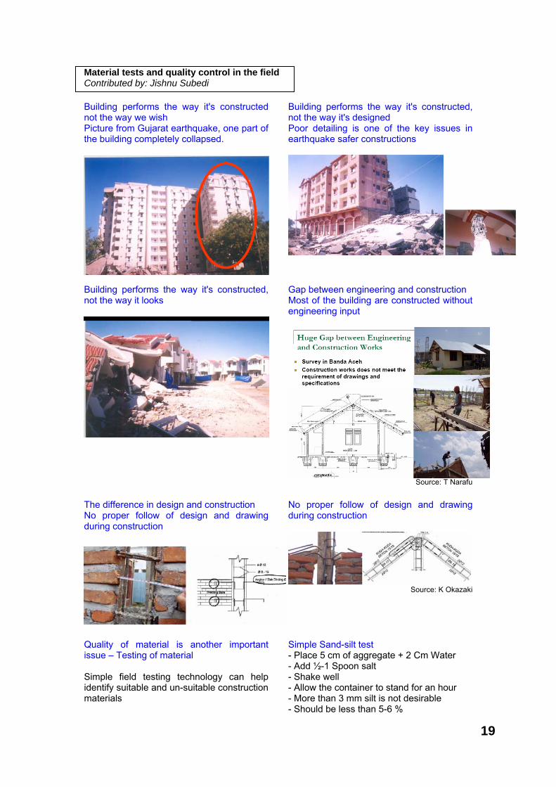
Material tests and quality control in the field Contributed by: Jishnu Subedi Building performs the way it's constructed not the way we wish Picture from Gujarat earthquake, one part of the building completely collapsed.
Building performs the way it's constructed, not the way it's designed Poor detailing is one of the key issues in earthquake safer constructions
Building performs the way it's constructed, not the way it looks
Gap between engineering and construction Most of the building are constructed without engineering input
Source: T Narafu
The difference in design and construction No proper follow of design and drawing during construction
No proper follow of design and drawing during construction
Source: K Okazaki
Quality of material is another important issue – Testing of material Simple field testing technology can help identify suitable and un-suitable construction materials
Simple Sand-silt test - Place 5 cm of aggregate + 2 Cm Water - Add ½-1 Spoon salt - Shake well - Allow the container to stand for an hour - More than 3 mm silt is not desirable - Should be less than 5-6 %
19

Simple Organic test - Sand 150 ml - Add Caustic Soda instead of Salt (3% -120 mL) - Dark color water means presence of organic matter Concrete mixing and gradation is important. Simple tools like a standard box can help a lot in proper mixing Non-engineered construction 1:2:3 (Cement: Sand: Aggregate) 1 Bag Cement = 0.3m x 0.3m x 0.353 2 box Sand 3 boxes Aggregate
Source: IAEE Manual
Field Test of mud mortar and bricks
Picture source: IAEE manual Simple Brick water absorption test - 1 Inch circle in brick with Wax Pencil - 20 drops of water - If all the water is absorbed within 90 seconds, brick
wetting is necessary. Use of simple field inspection form: Material
S. No Description Observation in the field
Remarks
1 Sand: Storage Water content General Quality
2 Brick: Brick quality Cleanliness Water absorption
3 Cement: Storage Purchased date
4 Aggregates: Grading Cleanliness Shape
5 Reinforcement bar: Quality Rust and physical condition
Field inspection form: Concrete work S. No Description Observation
in the field Remarks
1 Concrete mix: Ratio Procedure for concrete mixing Water cement ratio Is strength check done?
2 Placement of concrete: Pouring of concrete Compaction Shear key in column
3 Framework/ Centering/ Shuttering : Quality Safety
4 Curing: Done properly?
5 Reinforcement Bending Fabrication Placement
6 Detailing Stirrups Beam/column joint Lap length
7 General Eccentricity Member Connectivity
2 cm diameter balls, 48 hrs. dried should not break by pressing
2 cm diameter balls, 48 hrs. dried should not break by pressing
4 weeks sun-dried adobe should support weight of a man4 weeks sun-dried adobe should support weight of a man
20

Group work: Issues in constructions site The main objective of this group work is to discuss poor practices in building construction site from the experience of the participants and look for their suggestions. Time: 1 hr for group discussion, summarizing and 5 minutes for presentation Guideline questions and issues for discussion (Participants are encouraged to discuss other issues they feel relevant) General
• Relate your practical experience in the field and try to find out whether the construction quality you've observed is poor or not.
• What are the good practices? Any change from the past? • What are general problems in construction sites?
Problems in design
• Lack of awareness on need of engineering input - design • Lack of capacity of designer/ Sufficient numbers of designers not available/ Ethics
of designer • Lack of codes, guidelines and specifications • Codes, guidelines too difficult to follow/ Easy instructions necessary • How do you suggest improving the situations?
Problem in construction
• Materials not available • Problems of contractors • Capacity of masons/carpenters is lacking • Guidelines/ drawings for masons/carpenters required
Implementation/ Monitoring
• Is there proper monitoring mechanism for implementation of building code? • Capacity and sufficiency of manpower • Ethics
Other issues
• Lack of awareness among house owners/ contractors/ technical person/ masons • Whose responsibility for quality construction? • Is the situation improving from previous years?
What should be done to improve the situations?
21

After a brief introduction to the codal provisions, issues in the construction sites and quality control in the field, the participants carry out field observation of construction sites. A sample check-list and field inspection sheet is distributed to the participants. However, the participants are encouraged to make necessary changes to the sheet based on their experience. After field visit, the participants discuss in their group and make presentation of their experience in the field. The participants should also suggest any improvements, if necessary, in the distributed field inspection sheet. This approach is adopted to make the sheet practical and suitable to be used in the construction sites. Objective After completion of the module, the participants will be able:
1. To visualize the real problem in the site
2. To suggest on the good practices and bad practices in the field
3. To use field inspection check list for inspection and monitoring of construction sites
Module outline Field instructions Distribution of check-list, forms and material testing guidelines Field visit Filling the prescribed forms Drawing sketches and making notes The participants are expected to discuss the field visit in the group in the evening and prepare for presentation for tomorrow
Time 1 day Expected outcome Field experience to the participants and experience on using field inspection sheet Field inspection sheet with local adaptation for monitoring building construction sites Three construction sites were visited.
1. Health facility (Under construction) 2. Residential House (Completed but
retrofitting required) 3. School (Completed after retrofitting)
Field visit sites
Chapter 5
On-site Observation
1: Health facility site in Pidie 2: Residential timber building 3: Retrofitted school building
22
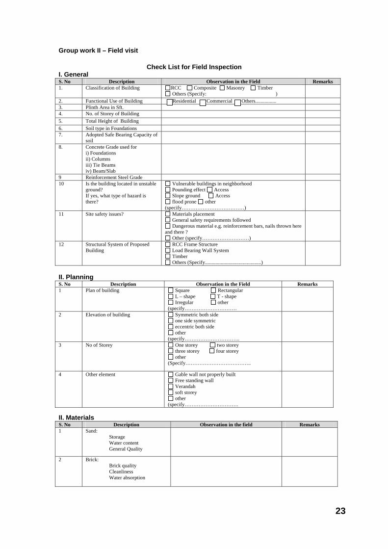
Group work II – Field visit
Check List for Field Inspection I. General S. No Description Observation in the Field Remarks 1. Classification of Building RCC Composite Masonry Timber
Others (Specify: )
2. Functional Use of Building Residential Commercial Others................ 3. Plinth Area in Sft. 4. No. of Storey of Building 5. Total Height of Building 6. Soil type in Foundations 7. Adopted Safe Bearing Capacity of
soil
8. Concrete Grade used for i) Foundations ii) Columns iii) Tie Beams iv) Beam/Slab
9 Reinforcement Steel Grade 10 Is the building located in unstable
ground? If yes, what type of hazard is there?
Vulnerable buildings in neighborhood Pounding effect Access Slope ground Access flood prone other
(specify………………………………)
11 Site safety issues?
Materials placement General safety requirements followed Dangerous material e.g. reinforcement bars, nails thrown here
and there ? Other (specify………………………)
12 Structural System of Proposed Building
RCC Frame Structure Load Bearing Wall System Timber Others (Specify...........................................)
II. Planning S. No Description Observation in the Field Remarks 1 Plan of building Square Rectangular
L – shape T - shape Irregular other
(specify…………………………
2
Elevation of building Symmetric both side one side symmetric eccentric both side other
(specify…………………………..
3 No of Storey One storey two storey three storey four storey other
(Specify………………………………..
4 Other element Gable wall not properly built Free standing wall Verandah soft storey other
(specify………………………….
II. Materials S. No Description Observation in the field Remarks 1 Sand:
Storage Water content General Quality
2 Brick: Brick quality Cleanliness Water absorption
23

S. No Description Observation in the field Remarks 3 Cement:
Storage Production date
4 Aggregates: Grading Cleanliness Shape
5 Reinforcement bar: Quality Rust and physical condition Storage
III. Construction
S. No Description According to actual Construction in Site
Remarks
1 Concrete mix: Ratio Procedure for concrete mixing Water cement ratio Is strength check done?
Placement of concrete: Pouring of concrete Compaction Shear key in column
Framework/ Centering/ Shuttering : Quality Safety
Curing: Done properly?
Reinforcement Bending Fabrication Placement
Detailing Stirrups Beam/column joint Lap length
General Eccentricity Member Connectivity
24

IV. For RCC Frame Structure S. No Description According to
Municipal Approval Drawing
According to actual Construction
in Site
Justification for variations
1 Foundation Details i) Depth ii) Sizes with naming: a. Corner b. Mid c. Face d. Others ......... ......... ......... iii) Reinforcements dia & spacing for foundations a. Corner b. Mid c. Face d. Others ......... ......... .........
2 Column Details i) Height from G. L. to Tie Beam Level (Plinth Height) ii )Floor Height iii) Sizes with naming: a. Corner b. Mid c. Face d. Others ......... ......... ......... iv) Reinforcements with naming a. Corner b. Mid c. Face d. Others ......... ......... ......... v) Stirrups dia. and Spacing
3 Earthquake safety features Follows ? • Ties at Joint • Development length / Lap
length
4 Combined Footing Details ( if provided) i) Size ii) Reinforcements: Top Jali Bottom Jali
5 Lower footing Tie Beam ( If Provided) i ) Size iii) Reinforcement Details iv) Stirrups dia. and Spacing
6 Plinth Tie Beam i ) Size iii) Reinforcement Details iv) Stirrups dia. and Spacing
7 Column Placing are in Grid? 8 Quality of Workmanship? Other Comments (if any)
25

This chapter summarizes experience of the participants after field visit to the construction sites. The participants conduct field visit divided in group, each of them fill site inspection check list, they discuss within the group and decide the content for group-work presentation. Objective After completion of the module, the participants will be able:
1. To understand the real and practical problems in site
2. To summarize on what is necessary next to improve actual construction practices
3. To implement the field inspection check list in their actual construction sites
Time 1/2 day Expected outcome Summary of field experience of the participants and their experience of the field visit Module outline Review of previous day field visit Group discussion and reparation for presentation Presentation on experience of field visit Finalization of checklist for field inspection Finalization of checklist for material testing
Field observation of the groups Group A
Health Facility Site Observation
Problem Consequence Solution Picture 1) Ring beam Joint Beam & column
1. Connection will release, ring beam will fall
1.Arrangement on joint and additional stick on column-slope
2) Column reinforce; connection with slope on fence
2. When earthquake, Column connection and slope is released
2. Lengthening of column footage into the slope is longer and additional stick from…
3) Crack on window 3. load is not distributed 3. Needs lintel beam under the window 4) Crack on wall, installed with Bata foam material
4. Crack on beam 4. Monitoring on Bata foam production; Enough curing when plastering
5) Sand quality, Aggregate 5. Concrete mixture is less
good (lack of concrete quality)
5. Mixture composition on concrete according to sand condition, aggregate
6) bar corrosion 6. Iron quality is changed 6. Clearance, Corrosion, Iron maintenance before used
Housing
Site Observation Problem Consequence Solution Picture Ring Beam reverse Position
On tied beam Provided with Bracing Additional or Reversing the beam position
School Facility Site Observation
Problem Consequence Solution Picture 1) Drainage iron cover 1. May injured people
during evacuation 1. Close all opened drainage for safety
Chapter 6
Lessons and Evaluation of Existing Construction Practices
26
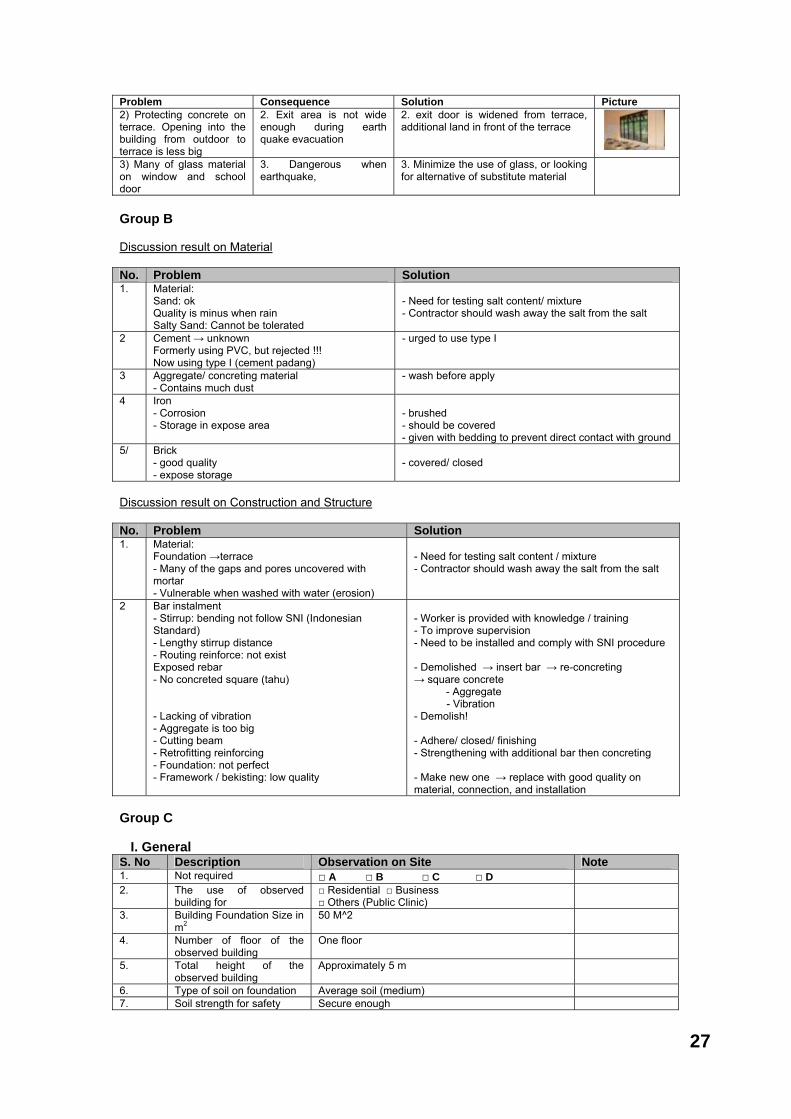
Problem Consequence Solution Picture 2) Protecting concrete on terrace. Opening into the building from outdoor to terrace is less big
2. Exit area is not wide enough during earth quake evacuation
2. exit door is widened from terrace, additional land in front of the terrace
3) Many of glass material on window and school door
3. Dangerous when earthquake,
3. Minimize the use of glass, or looking for alternative of substitute material
Group B Discussion result on Material No. Problem Solution 1. Material:
Sand: ok Quality is minus when rain Salty Sand: Cannot be tolerated
- Need for testing salt content/ mixture - Contractor should wash away the salt from the salt
2 Cement → unknown Formerly using PVC, but rejected !!! Now using type I (cement padang)
- urged to use type I
3 Aggregate/ concreting material - Contains much dust
- wash before apply
4 Iron - Corrosion - Storage in expose area
- brushed - should be covered - given with bedding to prevent direct contact with ground
5/ Brick - good quality - expose storage
- covered/ closed
Discussion result on Construction and Structure No. Problem Solution 1. Material:
Foundation →terrace - Many of the gaps and pores uncovered with mortar - Vulnerable when washed with water (erosion)
- Need for testing salt content / mixture - Contractor should wash away the salt from the salt
2 Bar instalment - Stirrup: bending not follow SNI (Indonesian Standard) - Lengthy stirrup distance - Routing reinforce: not exist Exposed rebar - No concreted square (tahu) - Lacking of vibration - Aggregate is too big - Cutting beam - Retrofitting reinforcing - Foundation: not perfect - Framework / bekisting: low quality
- Worker is provided with knowledge / training - To improve supervision - Need to be installed and comply with SNI procedure - Demolished → insert bar → re-concreting → square concrete - Aggregate - Vibration - Demolish! - Adhere/ closed/ finishing - Strengthening with additional bar then concreting - Make new one → replace with good quality on material, connection, and installation
Group C I. General S. No Description Observation on Site Note 1. Not required □ A □ B □ C □ D 2. The use of observed
building for □ Residential □ Business □ Others (Public Clinic)
3. Building Foundation Size in m2
50 M^2
4. Number of floor of the observed building
One floor
5. Total height of the observed building
Approximately 5 m
6. Type of soil on foundation Average soil (medium) 7. Soil strength for safety Secure enough
27

S. No Description Observation on Site Note 8 Concrete quality used for:
1) foundation 2) column 3) Tie beam 4) Beam/plate
Data Plan of K225 cannot be measure on site, testing is unavailable.
9. Steel Reinforce Quality Data plan is U39, but the fact there is no testing made available on site
10. Is the building constructed on unstable soil? If yes, what will be the risk?
□ Neighbour house is brittle □ Effect from demolished building □ No access, it is predicted the soil is quite stable
11. Security problems on site? □ Material placement □ Public safety is applied □ Hazard materials like reinforce steel and nail are
spread around
Material placement does not follow procedure
12
Structure system of the observed building
□ RCC frame structure □ Load bearing wall system □ Other (explain….)
RCC frame structure
II. Materials S. No Description Observation on Site Note 1. Sand’
- Retention of Water
- General Quality
Average, depending on weather, there was no water during observation Visually, sand contains mud
2. Brick: - Quality - Cleanness - Water absorbance
Average Good None
3. Cement: - Storage - Purchase date
Stored in a covered place, bed with plywood Unknown
4. Aggregate: - Gradation - Cleanness - Shape
Good Average Available in split and round
5. Steel Reinforce: - Quality - Condition & corrosion - Physical shape
Good Corrosion to some part of it Good enough
S. No Description Based on Construction Reality on Site Note 6. a) Concrete mixture:
Ratio Concrete mixture procedure Cement and Water ratio Is strength testing made?
N-a, there was no concreting activity during observation. Construction is in finishing stage.
6. b) Concrete placing: Concreting Compacting Shearkey on column
N-a, there was no concreting activity during observation. Construction is in finishing stage
6. c) Framework/Centering/Shuttering:Quality Security
N-a, there was no concreting activity during observation. Construction is in finishing stage.
6. d) Maintenance on Concrete: Is it done correctly?
N-a, there was no concreting activity during observation. Construction is in finishing stage
6. e) Reinforcing: Bending Fabricating Placement
N-a, there was no concreting activity during observation. Construction is in finishing stage. During fence work, binding work looked good.
6. f) Detailing: Stirrup Beam joint and column Length of routing
Unobservable after covered with concrete There was untied joint based on procedure Unobservable after covered with concrete
6. g) General: Eccentricity Member connectivity
Not happening Good
28

Group D CONSTRUCTION OF EARTHQUAKE RESISTANT BUILDINGS: FROM CODE TO PRACTICE
Projects : District Health Centre, Wooden House, School Address : Pidie Jaya Group Discussion : GROUP -- D DISCUSSION ON OBSERVATION OF CONSTRUCTION MATERIAL AND IMPLEMENTATION DURING FIELD VISIT A CONSTRUCTION MATERIAL
FIELD OBSERVASION RECOMMENDATION 1 Sand
a Sand taken from the shore a If soaked it will produce LIGHT YELLOW liquid
b Very fine/ not rough b Should not contain any salt material
c Dirty c Fine and rough grain of sand, and not crumpled when crasp
d high mud concentration 2 Brick Foam
a Fragile a Bata foam should be installed is the full one, not the broken one
b It was found out that many broken oieces of brick foam used in the wall construction
b Undertaking watering/before brick foam is installed to prevent mixed cement water not dry early
3 Red Brick
a Brick are broken by water a size shape is good and standard and it is firm
b Not sufficient burning process b Sound is tingling when knocked
c The material contained clay and sand c Soaked in the water for 24 hours
and it should not be appart Improper storaging 4 Cement
a It was doubtful if cement type 40 kg Semen Padang brand was type II a
All of type I and II are usable, depend on the use and condition in this case the type II is better.
b Circulation of cement is not clear Type I is good
b Stock count at the warehouse should indicate the old and new cement on the stock
5 Aggregate
a Material is good but storage in the field is less good/mixed with land a Stone break minimum of 3 sides
b grain size should not exceed 5 mm
c Broken material should less than 30 %
d Should not contain mud more than 1 %
6 Steel reinforcing
a Storing just lay on the ground and can caused corrosion a Prior to concreting, iron should be
corrosion free
b No cover b After installation, iron should be concreted
c c Diameter should be precise
29
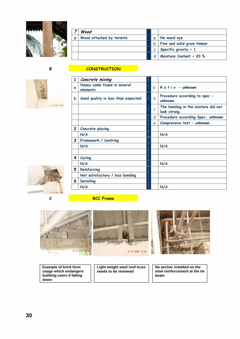
7 Wood a Wood attacked by termite a No wood eye b Fine and solid grain timber c Specific gravity < 1
d Moisture Content < 20 %
B CONSTRUCTION
1 Concrete mixing
a Honey comb found in several elements a R a t i o - unknown
b Sand quality is less than expected b Procedure according to spec - unknown
c The bonding in the mixture did not look strong
d Procedure according Spec- unknown e Compressive test - unknown 2 Concrete placing N/A N/A 3 Framework / Centring N/A N/A 4 Curing N/A N/A 5 Reinforcing Not satisfactory / less bonding 6 Detailing N/A N/A
C RCC Frame
Example of brick form usage which endangers building users if falling down
Light weight steel roof truss needs to be reviewed
No anchor installed on the steel reinforcement at the tie beam
30
As proper guideline is not followed during construction of buildings, hundreds of thousands of buildings are raised in such a way that they become vulnerable during earthquake. The vulnerable buildings need to identified and any of the following approach should be taken in order to minimize loss of life and property during the earthquake: i) Leave as it is or with minor repair if the building is safe; ii) Retrofit the building in order to increase its strength; iii) Demolish the building as replacement is more cost effective. Identification of buildings vulnerability against earthquake is a complicated and time consuming process. A detailed investigation of the existing conditions, modeling of the building in computer software and detailed analysis is necessary for identifying exact need of retrofitting. As the training is design to give the overview on vulnerability assessment and retrofitting and allocated the limited time, a simple identification with spending 1-2 hrs. in each building has been proposed. A simplified rapid visual screening method is described here which needs to be adapted to local conditions as the building types described in the method rarely match the building types in many developing countries.
Time Five hrs. Expected outcome Understanding of the need to develop simple vulnerability assessment tool suitable for types of building existing in the region Understanding of simple retrofitting process Objective After completion of the module, the participants will be able to
1. Understand the necessity of retrofitting
2. Use simple vulnerability assessment method
3. Understand the retrofitting process and technology
Module outline Simple vulnerability analysis methodology Group practice on vulnerability methodology and discussion on the procedure Review of vulnerability analysis methodology
Retrofitting – Assessment, design and construction method Continue Retrofitting
Rapid visual inspection for vulnerability assessment of existing buildings Contributed by: Jishnu Subedi Why vulnerability assessment tool? - Large nos. of lives and properties are lost due to the collapse of vulnerable buildings.
- Lives and properties damage can be reduced, if
- Vulnerability assessment is done prior to great disaster.
- Prior action (remedy) is taken to reduce the
vulnerability Vulnerability Assessment Tool essential first step to save life and properties
Types of assessment methodologies - Detailed e.g. Analysis of individual building - General according to building typology - Rapid for individual building
Chapter 7
Vulnerability Assessment and Retrofitting
31
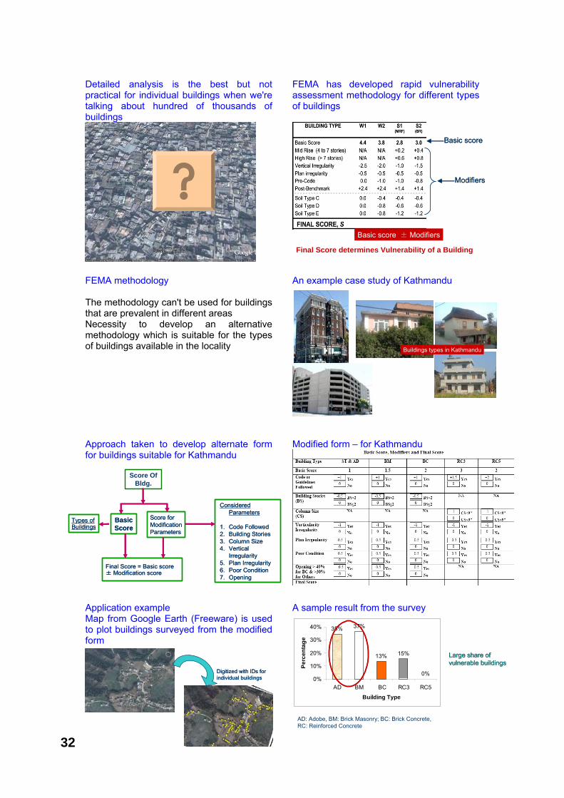
Detailed analysis is the best but not practical for individual buildings when we're talking about hundred of thousands of buildings
FEMA has developed rapid vulnerability assessment methodology for different types of buildings
FEMA methodology The methodology can't be used for buildings that are prevalent in different areas Necessity to develop an alternative methodology which is suitable for the types of buildings available in the locality
An example case study of Kathmandu
Approach taken to develop alternate form for buildings suitable for Kathmandu
Modified form – for Kathmandu
Application example Map from Google Earth (Freeware) is used to plot buildings surveyed from the modified form
A sample result from the survey
Basic scoreBasic score
ModifiersModifiers
Basic score ± Modifiers
Final Score determines Vulnerability of a Building
Buildings types in KathmanduBuildings types in Kathmandu
Score Of Bldg.
Basic Score
Score for Modification Parameters
Basic Score
Score for Modification Parameters
Considered Parameters
1. Code Followed2. Building Stories 3. Column Size4. Vertical
Irregularity5. Plan Irregularity6. Poor Condition7. Opening
Considered Parameters
1. Code Followed2. Building Stories 3. Column Size4. Vertical
Irregularity5. Plan Irregularity6. Poor Condition7. Opening
Types of BuildingsTypes of Buildings
Final Score = Basic score ± Modification scoreFinal Score = Basic score ± Modification score
Digitized with IDs for individual buildingsDigitized with IDs for individual buildings
35% 37%
13% 15%
0%0%
10%
20%
30%
40%
AD BM BC RC3 RC5
Building Type
Perc
enta
ge
AD: Adobe, BM: Brick Masonry; BC: Brick Concrete, RC: Reinforced Concrete
Large share of Large share of vulnerable buildingsvulnerable buildingsLarge share of Large share of vulnerable buildingsvulnerable buildings
32
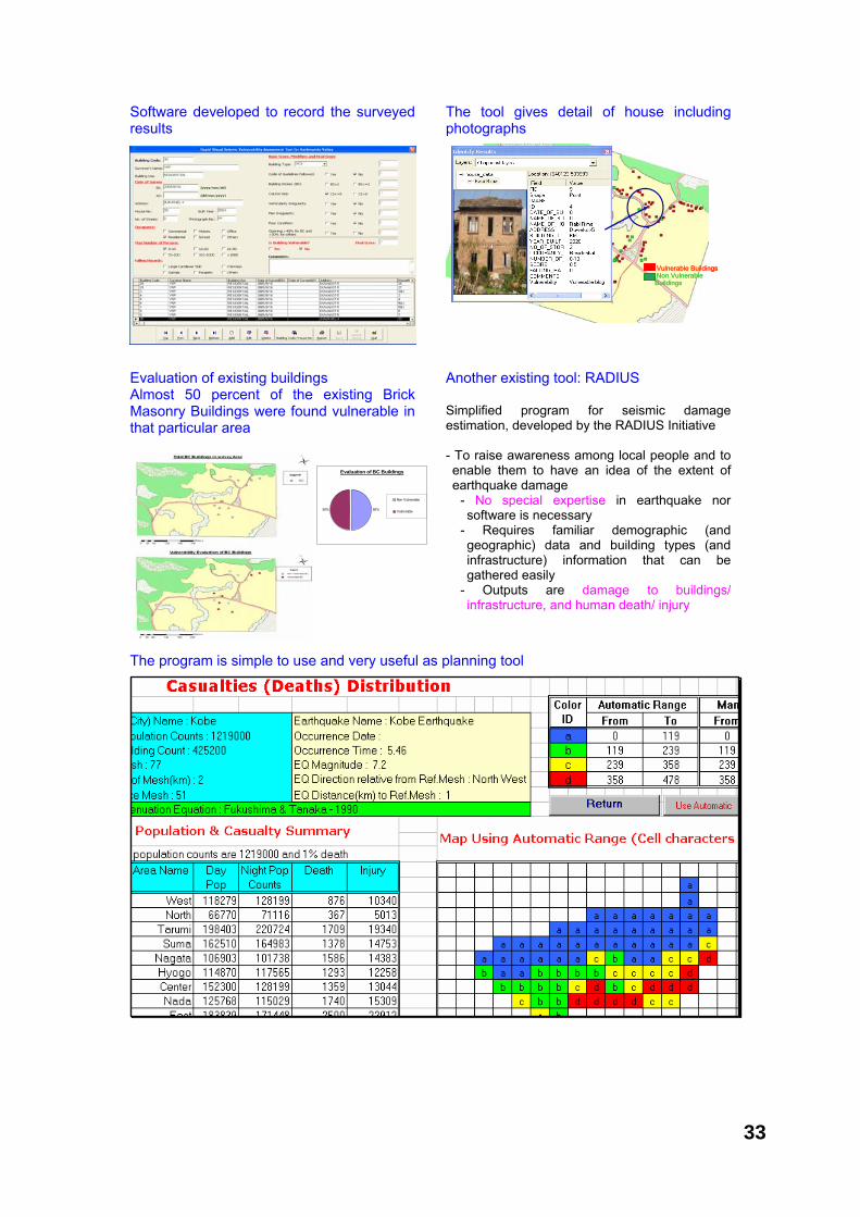
Software developed to record the surveyed results
The tool gives detail of house including photographs
Evaluation of existing buildings Almost 50 percent of the existing Brick Masonry Buildings were found vulnerable in that particular area
Another existing tool: RADIUS Simplified program for seismic damage estimation, developed by the RADIUS Initiative - To raise awareness among local people and to enable them to have an idea of the extent of earthquake damage
- No special expertise in earthquake nor software is necessary
- Requires familiar demographic (and geographic) data and building types (and infrastructure) information that can be gathered easily
- Outputs are damage to buildings/ infrastructure, and human death/ injury
The program is simple to use and very useful as planning tool
Vulnerable BuildingsNon Vulnerable Buildings
Vulnerable BuildingsNon Vulnerable Buildings
Vulnerable BuildingsNon Vulnerable Buildings
Evaluation of BC Buildings
50%50%
Non Vulnerable
Vulnerable
33
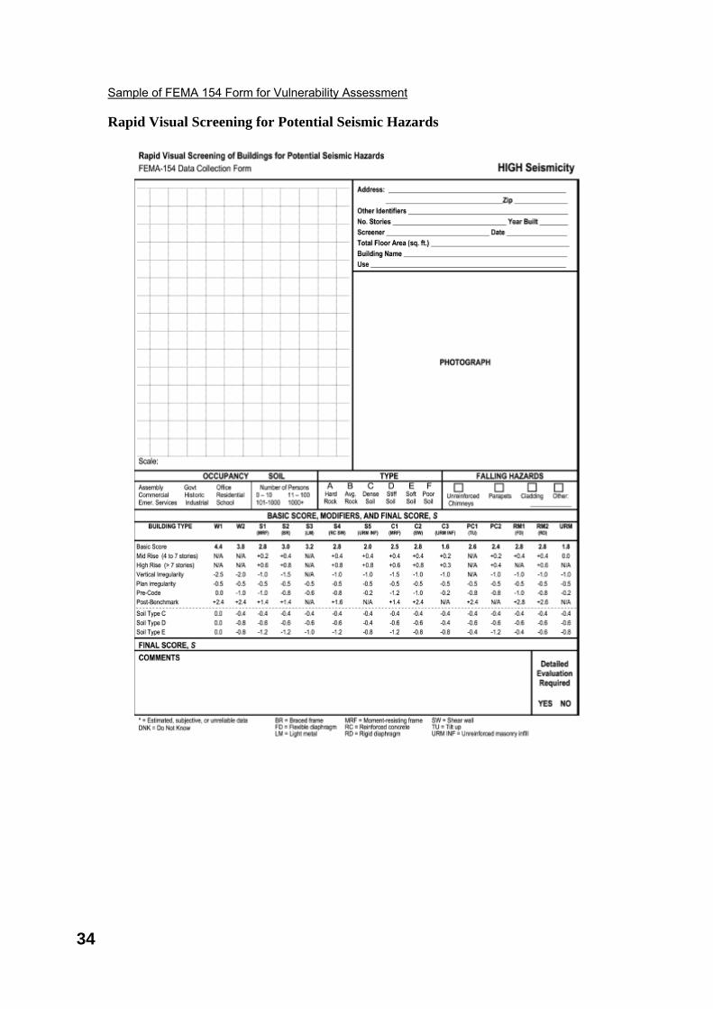
Sample of FEMA 154 Form for Vulnerability Assessment Rapid Visual Screening for Potential Seismic Hazards
34
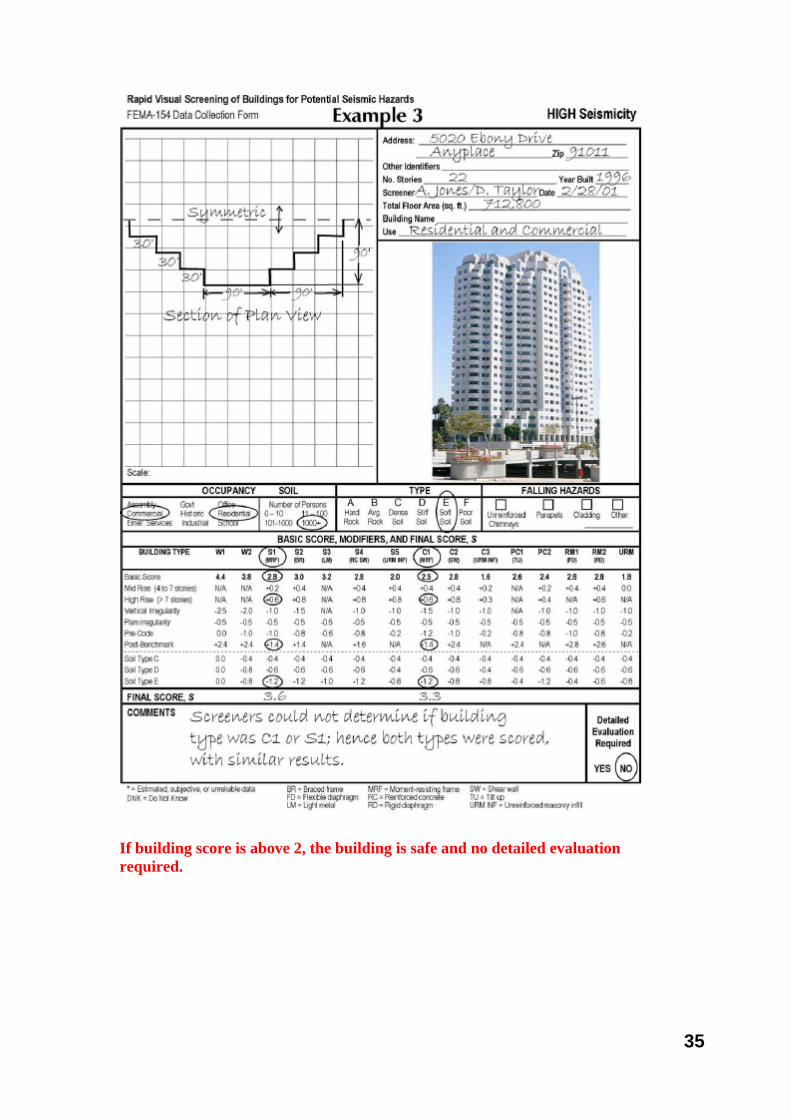
If building score is above 2, the building is safe and no detailed evaluation required.
35
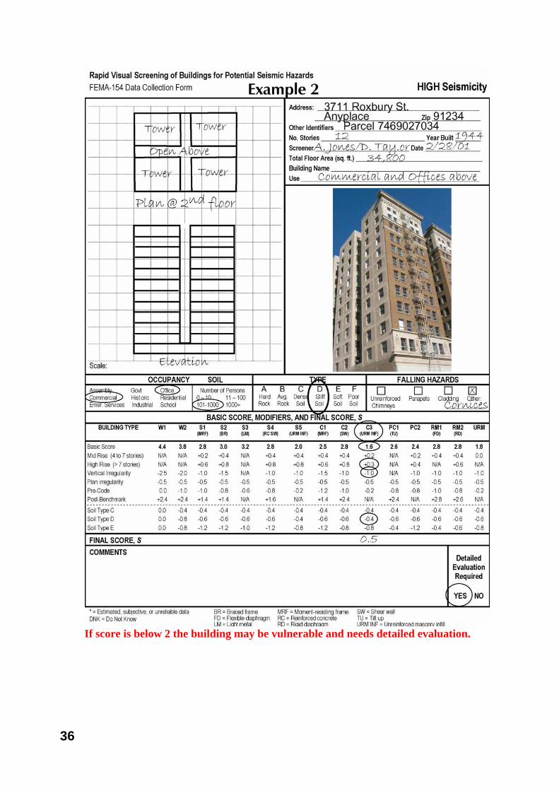
If score is below 2 the building may be vulnerable and needs detailed evaluation.
36
Retrofitting: Assessment, Design and construction methods Contributed by: Hari Darshan Shrestha Retrofitting as a new option to make existing structures safe and reduce the risk There are millions of houses Vulnerable to Earthquakes in around the world and Millions of People are in the houses are at risk Solution - To dismantle all and build new - Economically not viable, - Lack of affordability - Retrofitting – Viable and affordable Why is retrofitting getting wider acceptance? Retrofitting is only solution to strengthen - Heritage building and structures
- Vulnerable buildings and structures
Why and where retrofitting? Why Retrofitting - To Conserve Heritage structure - To Preserve historical architecture - To Preserve Land mark structure - to make structure earthquake resistant - To Strengthen the existing vulnerable structure - Economically viable - Affordable - Time saving
When and what type? Existing structure Historical important structure Strategically important infrastructure Conservation purpose Economically viable (cost of retrofitting < 30%) Huge intervention Constructed before Codal provision and before revision Constructed without engineering input Constructed against the engineering ethics
Basic features of retrofitting Reduce falling hazards Make structural members (walls, column, roof etc) act integrally Strengthen weak members and weak links Eliminate possibility of sudden and catastrophic collapse Create time for escape and education path
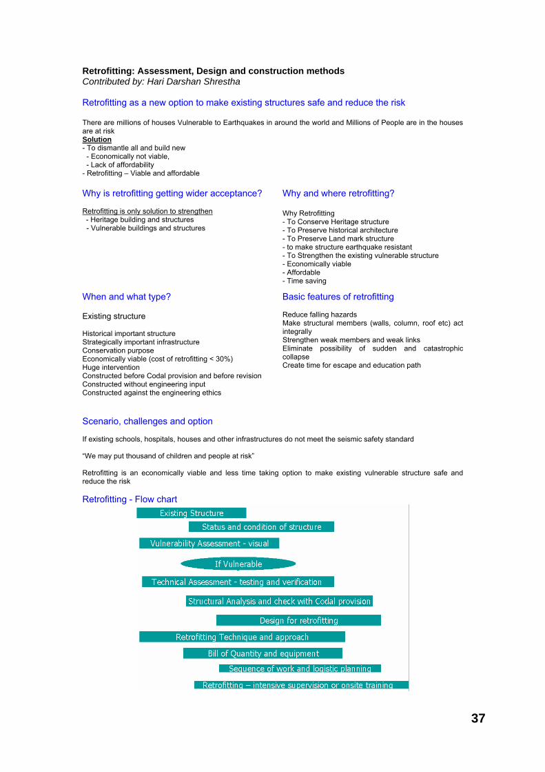
Scenario, challenges and option If existing schools, hospitals, houses and other infrastructures do not meet the seismic safety standard “We may put thousand of children and people at risk” Retrofitting is an economically viable and less time taking option to make existing vulnerable structure safe and reduce the risk Retrofitting - Flow chart
37
Case study Save the children School Safety Initiative The case for earthquake safe schools and houses Reducing vulnerability of School Children and people to Earthquakes
Existing structures and Issues School buildings Houses Status and Condition of Structure Cracks on walls Cracks on structural member Poor workmanship Poor quality construction Built without proper design and supervision Did not followed the Code and practice Complain / issues
Vulnerability assessment of existing Buildings Rapid visual inspection and assessment Collection of design and drawing Topographical information of site Site measurement of main structural member Inspection of cracks and location Judgment Quality construction Evaluate Workmanship Inspection of Material used and its quality
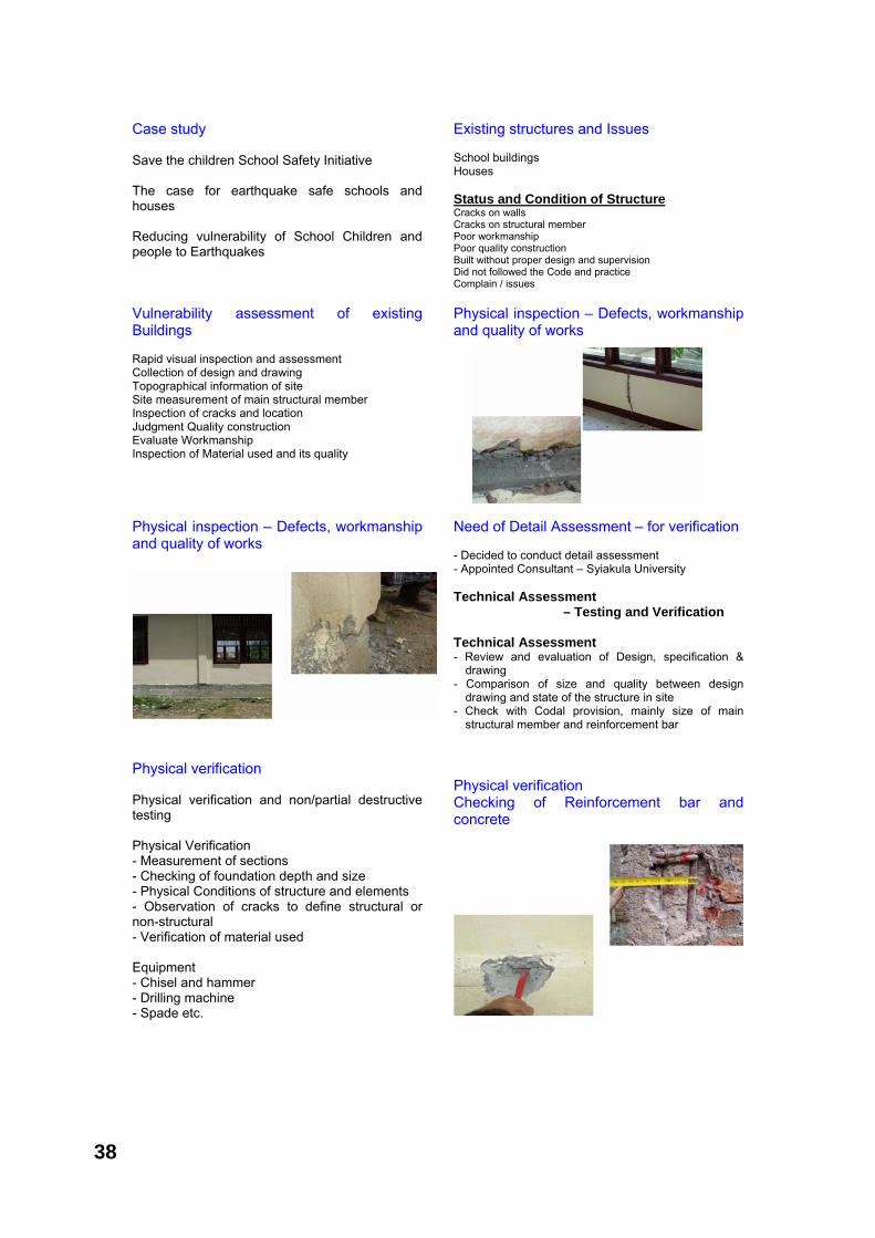
Physical inspection – Defects, workmanship and quality of works
Physical inspection – Defects, workmanship and quality of works
Need of Detail Assessment – for verification - Decided to conduct detail assessment - Appointed Consultant – Syiakula University Technical Assessment
– Testing and Verification Technical Assessment - Review and evaluation of Design, specification &
drawing - Comparison of size and quality between design
drawing and state of the structure in site - Check with Codal provision, mainly size of main
structural member and reinforcement bar
Physical verification Physical verification and non/partial destructive testing Physical Verification - Measurement of sections - Checking of foundation depth and size - Physical Conditions of structure and elements - Observation of cracks to define structural or non-structural - Verification of material used Equipment - Chisel and hammer - Drilling machine - Spade etc.
Physical verification Checking of Reinforcement bar and concrete
38
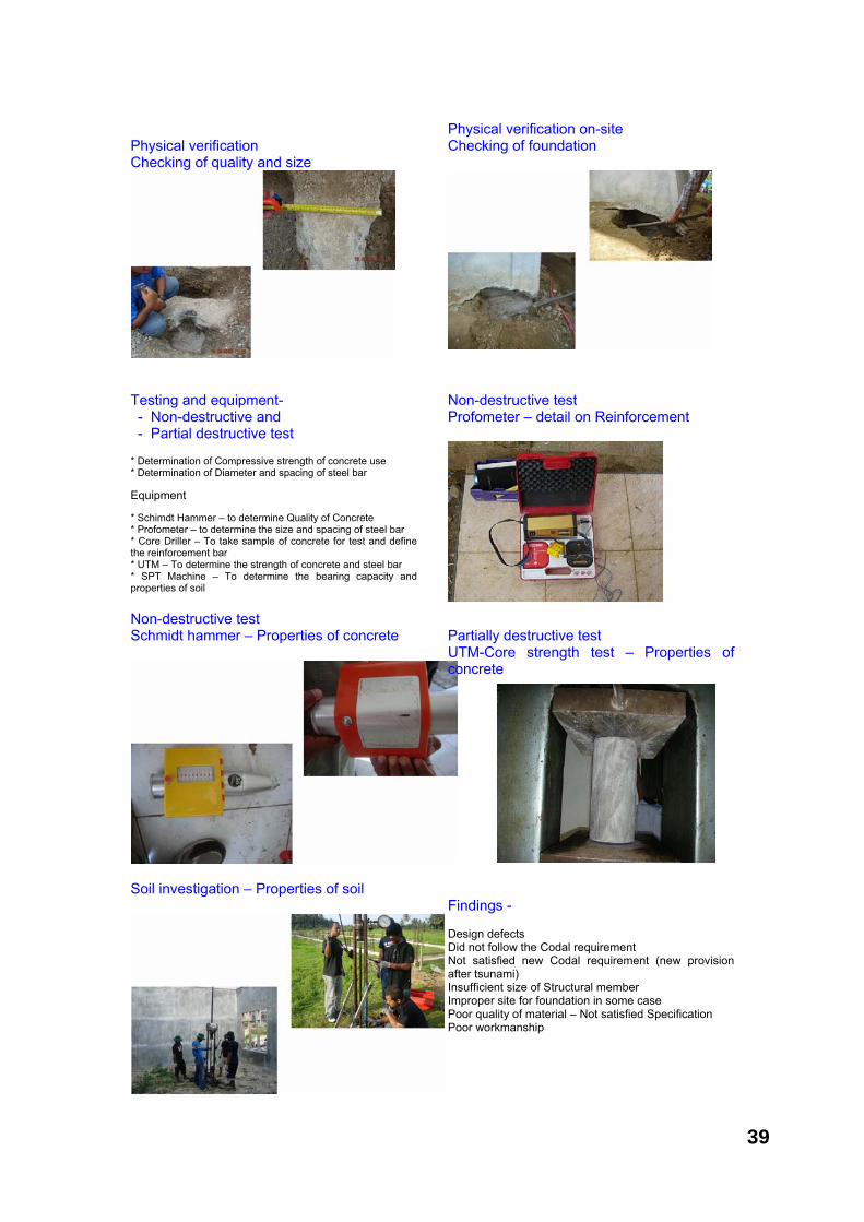
Physical verification Checking of quality and size
Physical verification on-site Checking of foundation
Testing and equipment- - Non-destructive and - Partial destructive test
* Determination of Compressive strength of concrete use * Determination of Diameter and spacing of steel bar Equipment * Schimdt Hammer – to determine Quality of Concrete * Profometer – to determine the size and spacing of steel bar * Core Driller – To take sample of concrete for test and define the reinforcement bar * UTM – To determine the strength of concrete and steel bar * SPT Machine – To determine the bearing capacity and properties of soil
Non-destructive test Profometer – detail on Reinforcement
Non-destructive test Schmidt hammer – Properties of concrete
Partially destructive test UTM-Core strength test – Properties of concrete
Soil investigation – Properties of soil
Findings - Design defects Did not follow the Codal requirement Not satisfied new Codal requirement (new provision after tsunami) Insufficient size of Structural member Improper site for foundation in some case Poor quality of material – Not satisfied Specification Poor workmanship
39
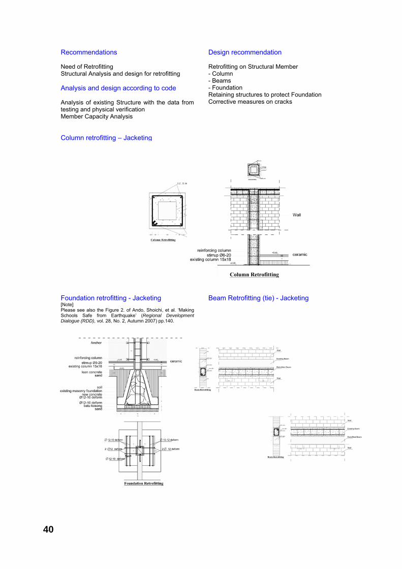
Recommendations Need of Retrofitting Structural Analysis and design for retrofitting Analysis and design according to code Analysis of existing Structure with the data from testing and physical verification Member Capacity Analysis
Design recommendation Retrofitting on Structural Member - Column - Beams - Foundation Retaining structures to protect Foundation Corrective measures on cracks
Column retrofitting – Jacketing Foundation retrofitting - Jacketing [Note] Please see also the Figure 2. of Ando, Shoichi, et al. ‘Making Schools Safe from Earthquake’ (Regional Development Dialogue (RDD), vol. 28, No. 2, Autumn 2007) pp.140.
Beam Retrofitting (tie) - Jacketing
40
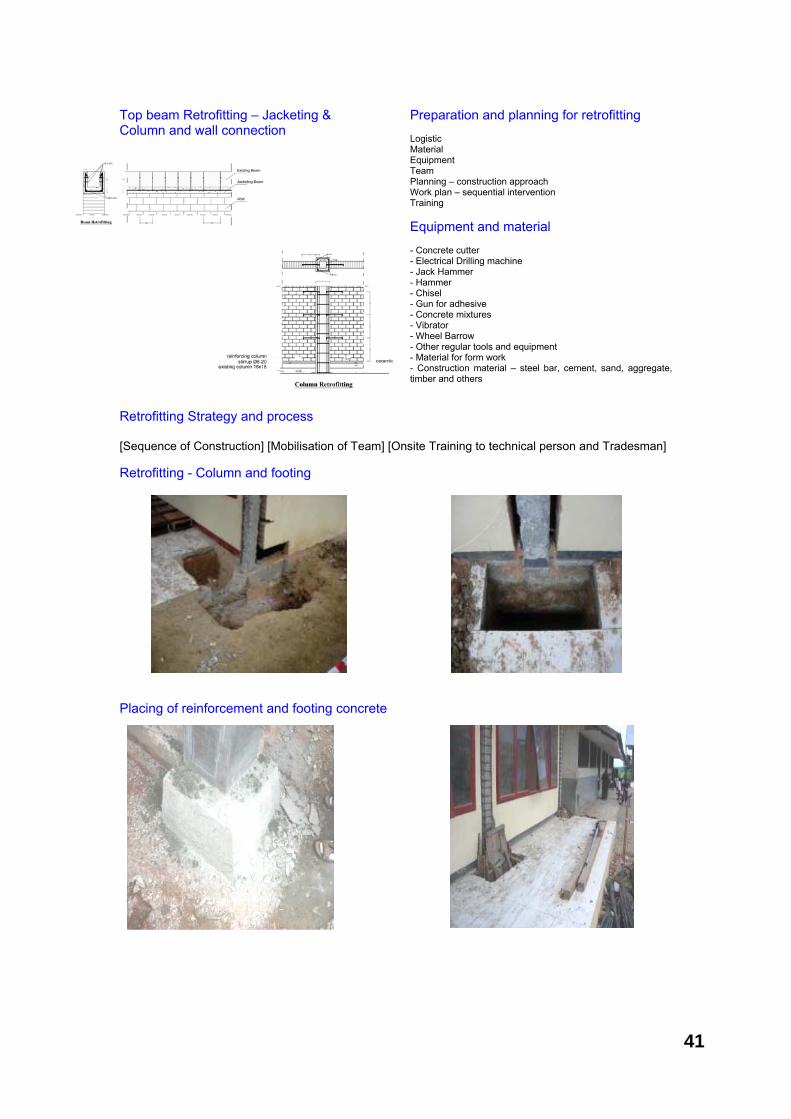
Top beam Retrofitting – Jacketing & Column and wall connection
Preparation and planning for retrofitting Logistic Material Equipment Team Planning – construction approach Work plan – sequential intervention Training Equipment and material - Concrete cutter - Electrical Drilling machine - Jack Hammer - Hammer - Chisel - Gun for adhesive - Concrete mixtures - Vibrator - Wheel Barrow - Other regular tools and equipment - Material for form work - Construction material – steel bar, cement, sand, aggregate, timber and others
Retrofitting Strategy and process [Sequence of Construction] [Mobilisation of Team] [Onsite Training to technical person and Tradesman] Retrofitting - Column and footing Placing of reinforcement and footing concrete
41
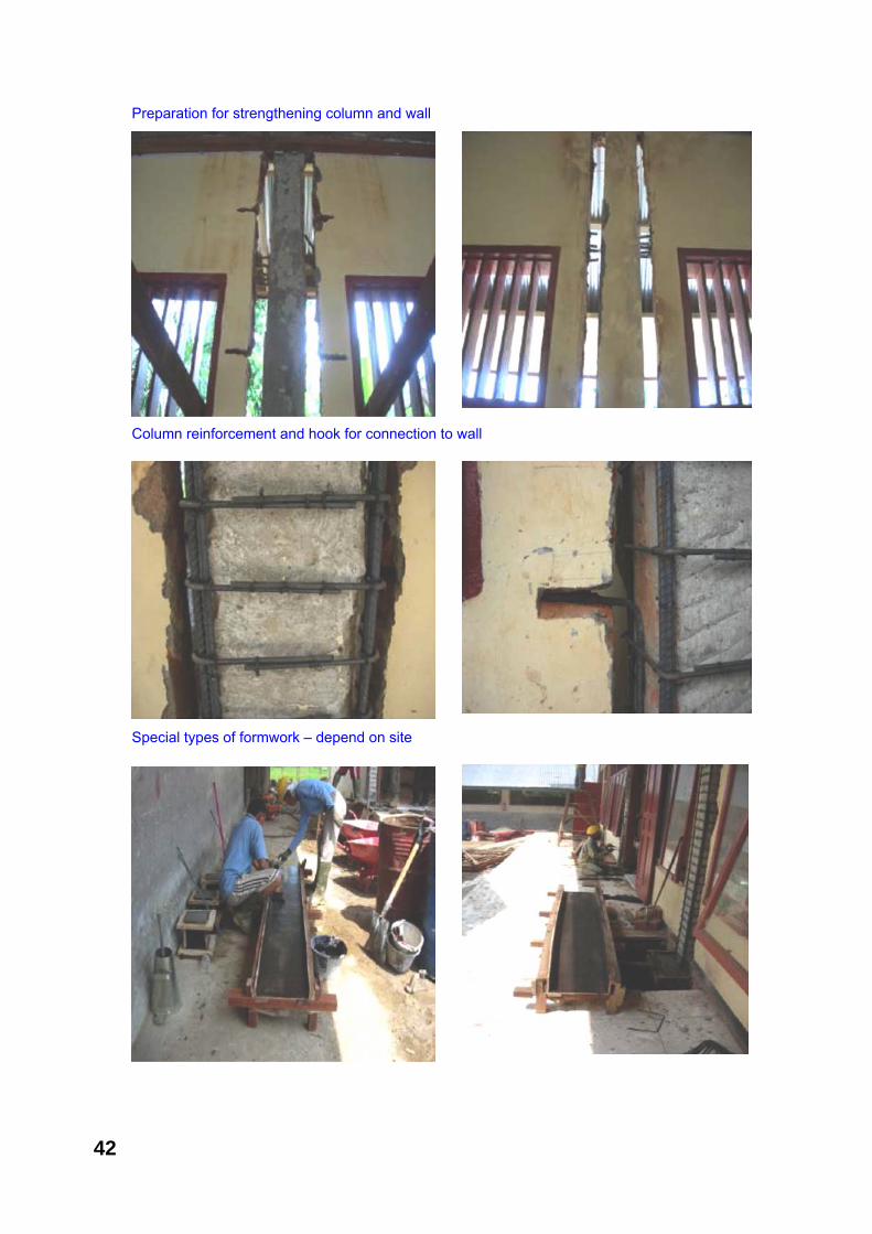
Preparation for strengthening column and wall Column reinforcement and hook for connection to wall Special types of formwork – depend on site
42
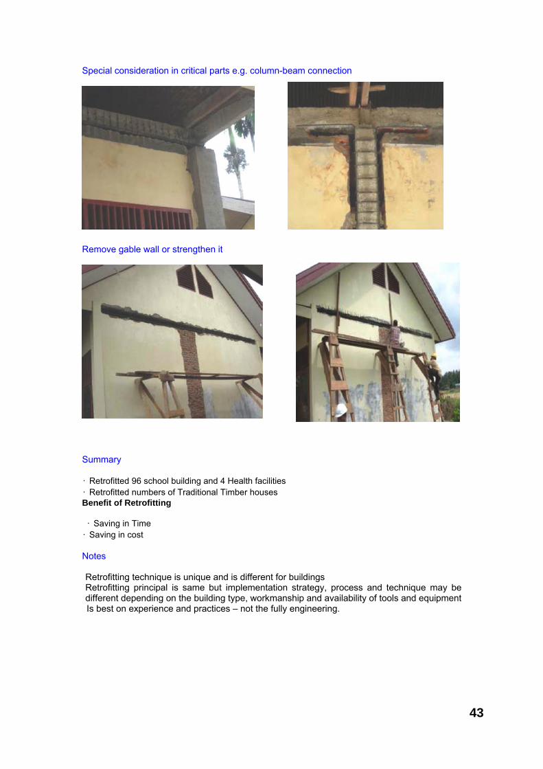
Special consideration in critical parts e.g. column-beam connection Remove gable wall or strengthen it Summary • Retrofitted 96 school building and 4 Health facilities • Retrofitted numbers of Traditional Timber houses Benefit of Retrofitting • Saving in Time
• Saving in cost Notes Retrofitting technique is unique and is different for buildings Retrofitting principal is same but implementation strategy, process and technique may be different depending on the building type, workmanship and availability of tools and equipment Is best on experience and practices – not the fully engineering.
43
Objective The main objective of this module is to give overall picture of housing safety and disaster risk reduction in the context of current global initiatives. Module outline Overall review of the disaster risk reduction and global initiatives
Time 1-2 hrs Expected outcome Housing safety in the context of overall disaster risk reduction initiatives and sustainable development
Living Closely with Earthquake: Specific for treating building as activity place Contributed by: Kasru Susilo (Translated from Bahasa, Indonesia) Living with Risk - a Global Review of Disaster Reduction Initiatives Living Closely with Disaster: is a dynamic project which requires sustainable initiatives to maintain global and systemic review of the on-going disaster risk reduction activities. Applied frame work to measure the disaster risk reduction initiatives has been a good starting point which enables to play role in achieving International Strategic Goal for Disaster Reduction
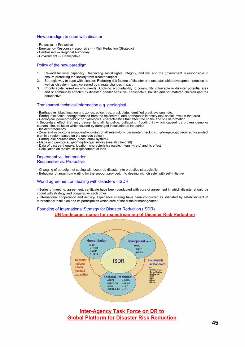
Sequence of description 1. Our behaviour of coping with the disaster? 2. New paradigm to deal with disaster (earthquake)! 3. World agreement in dealing with disaster by the disaster close-living paradigm and disaster risk reduction strategy 4. Community Based Disaster Management? 5. Reality of PBBM/CBDRM progress in Indonesia 6. At the moment Disaster Threat comes suddenly, how would our behaviour be with the reality 7. What can we (local government and community in the disaster area) do to cope with disaster (such as earthquake)
Knowing the disaster What is that actually the: - Danger - Disaster - Disaster Risk - Vulnerable to Disaster - Disaster Risk Reduction
Definition of Disaster Danger: Condition or situation that potentially possible to cause a disaster and if it is occurred, it is due to those affected by the disaster are not ready and unable to cope with it Disaster: Incident or a series of incidents which threaten and interrupt the life and society living caused by natural/non natural and human factor so as resulting in death toll, environmental damage, property loss, and psychological impact. (article 1 clause of Law no. 24/ 2007 of disaster prevention) Disaster Risk: Potential of loss caused by disaster in a area within particular period, which may be in the form of death, wound, disease, life-threatening, insecurity, refuge, damage or property loss, and community activity disturbance (article 1 clause 17 of Law no. 24/2007 of disaster prevention)
Living closely with disaster? Proactive Behaviour Condition or situation which highly possible to cause a disaster when the people are not prepared and capable to deal the disaster Effective behaviour Incident or series of incident which threatening and disturbing the life and social living which caused by natural/ non-natural and human factor so as it causes death toll, environmental disruption and psychological impact. (article 1 clause 1 of Law no. 24/ 2007 of Disaster Prevention) (Strategy) Settled with Disaster Potential of loss caused by disaster in a area within particular period, which may be in the form of death, wound, disease, life-threatening, insecurity, refuge, damage or property loss, and community activity disturbance. (article 1 clause 17 of Law no 24/2007 of disaster prevention)
Chapter 8
Conclusion and the way forward for Disaster risk reduction
44
New paradigm to cope with disaster - Re-active → Pro-active - Emergency Response (responsive) → Risk Reduction (Strategic) - Centralised → Regional Autonomy - Government → Participative Policy of the new paradigm 1. Reward for local capability: Respecting social rights, integrity, and life, and the government is responsible to
ensure protecting the society from disaster impact 2. Strategic way to cope with disaster: Reducing risk factors of disaster and unsustainable development practice as
well as disaster impact worsened by climate changes impact 3. Priority scale based on who needs: Applying accountability to community vulnerable in disaster potential area
and or community affected by disaster, gender sensitive, participative, holistic and not matured children and fair perspective
Transparent technical information e.g. geological - Earthquake risked location and zones, epicentres, crack plate, identified crack systems, etc. - Earthquake scale (energy released from the epicentres) and earthquake intensity (soil shake level) in that area - Geological, geomorphologic or hydrological characteristics that affect the shake and soil deformation - Secondary effect that may cause: landfall, landslide, collapsing, flooding in which caused by broken damp or tsunami; fire, pollution which caused by damaged installation at industries - Incident frequency - Zone and micro-zone (mapping/recording of all seismologic parameter, geologic, hydro-geologic required for protect plan in a region, based on the sources below) - Earthquake sources map (crack, crack system) - Maps and geological, geomorphologic survey (see also landfall) - Data of past earthquake, location, characteristics (scale, intensity, etc) and its effect - Calculation on maximum displacement of land Dependent vs. Independent Responsive vs. Pro-active - Changing of paradigm of coping with occurred disaster into proactive strategically - Behaviour change from waiting for the support provided, into dealing with disaster with self-initiative World agreement on dealing with disasters - ISDR - Series of meeting, agreement, certificate have been conducted with core of agreement in which disaster should be coped with strategy and cooperative each other - International cooperation and activity/ experience sharing have been conducted as indicated by establishment of international institution and its participation which care of the disaster management Founding of International Strategy for Disaster Reduction (ISDR)
45
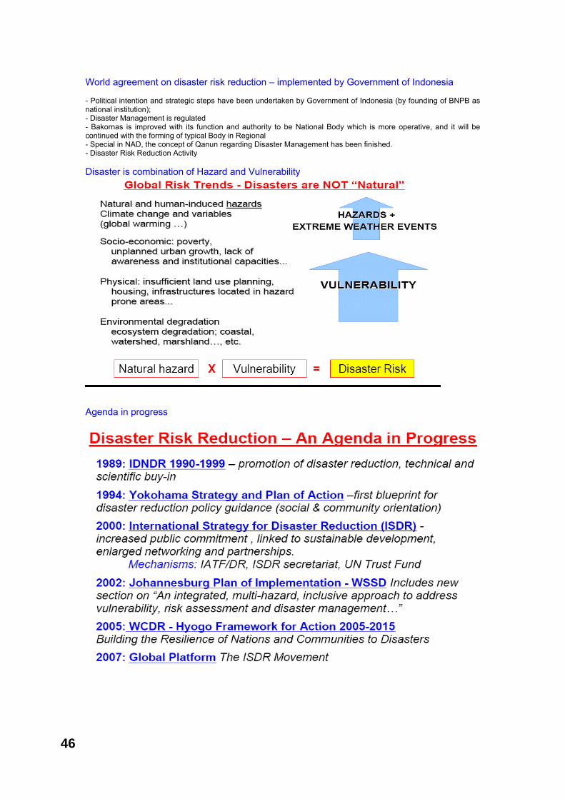
World agreement on disaster risk reduction – implemented by Government of Indonesia - Political intention and strategic steps have been undertaken by Government of Indonesia (by founding of BNPB as national institution); - Disaster Management is regulated - Bakornas is improved with its function and authority to be National Body which is more operative, and it will be continued with the forming of typical Body in Regional - Special in NAD, the concept of Qanun regarding Disaster Management has been finished. - Disaster Risk Reduction Activity Disaster is combination of Hazard and Vulnerability Agenda in progress
46

UUPB (Undang-Undang Penaggulangan Bencana) The Law of Disaster Response number 24 year 2007 regulate: Respect to the humanity and appreciate the local culture (Chapter 2) and protection to the community who affected by disaster (Chapter 3) National and local government are responsible on managing disaster response (Chapter 3 Section 5 – 8) Right and Responsibility of the Community in relation to the Disaster Response (Chapter 5 Section 26) Participatory Planning in Disaster Response and Developing Disaster Awareness Culture (Chapter 5 Section 37) Space planning and Live Environment Management and Strengthening the Community Social Hardiness (Chapter 5 Section 38) National Action Plan (NAP) of PRB released in 2007 - Emphasize on the importance of platforms, priority, action plan and mechanism relative to implementation of PB and basic institutional frame toward disaster prevention in Indonesia - Elaborating stakeholders interest and responsibility through coordination and participation process in line with HFA- the Hyogo Framework for Action - Provide direction/ guidelines and information that can facilitate the decision makers in delivering their commitment that complies with their sector and priority based on firm and systemic basis 5 Priority activities in NAP-PRB 2006-2009 1. Integrating PRB in priority policy of national and regional development with strong institutional basis for its implementation; 2. Identification, examination and observation in the risk reduction and early warning implementation; 3. To apply the knowledge, innovation and education in order to create safe and secure society in all level including the community; 4. Risk factors reduction 5. Enforcement of alert for effective response to all level Community based disaster risk reduction - Disaster Risk Management (DRM) or Disaster Risk Reduction (PRB): behaviour approach on disaster threat with paradigm that readiness to deal with disaster will relieve the burden while disaster occurred - CBDRM (community based DRM) or Community Based Disaster Risk Reduction is one of PRB strategies that relies on local community cooperation - CBDRM can be related with local community development goal, such as local economy CBDM for a resilient society - An approach encouraging grass root community in performing self-interpretation upon the risk he is dealing with, by maximizing the use of his own source - Perform prevention priority/ risk reduction he encountered, by “his own way” - Reduce, observe, and evaluate his performance in terms of disaster risk reduction effort Reality about progress of CBDRM in Indonesia Existing study result stated that: Indonesia is still not ready to deal with medium and big scale of disaster incident. At least, at software and hardware: infrastructural policy and institutional readiness for disaster budget capacity, physical infrastructure, absence of planning by disaster contingency in the province and district level, facility and infrastructure are indeed not ready for future big disaster. Conceptual challenge for CBDRM - There has been no equal concept and PRB-BK Frame Work and standardization in the form of Community Based Disaster Risk Reduction Guidelines (PRB-BK) as a mutual guideline including the stakeholders; - Unformulated parameter, indicated and “tool” to value the PRB-BK practices impact in the field - PRB-BK practices are still “donor driven” or outside community initiative, and it will be implicated on the community sense of belonging toward PRB-BK itself; - PRB-BK initiatives are still partial and directed on local capacity enforcement - PRB-BK practices have not explored local sources in optimal way including local wise which is summed up in the Community Action Plan (RAK) or “Rencana Aksi Masyarakat” - PRB-BK practices have not been integrated in other sectors, such as health, community income improvement, (Livelihoods) and other sectors; - There has not been a exchange process of experience related with the practice of “lesson learnt” on PRB-BK amongst PRB-BK stakeholders; Concept, Draft, New Paradigm Programme that have been reviewed, implemented, and made for Disaster Management Programme, especially in disaster reduction strategy are in fact has not fully socialized to the community (candidate) to be affected by disaster.
47
Commitment about disaster management - Commitment rose after disaster occurred. There is awareness that disaster should be handled. - Government commitment does not deny from existing tupoksi by referring to PROTAP and SOP - Community tend to depend on aid. Anomaly happened in ornop working area - Privates consider that it is not its mandate. Commitment on asset security (staffs) Review of risk - Government (central & province) conducts tupoksi in the form of threat review regular work. Cooperation between central and province not always happened. TOR based normative review output is not public oriented - Ornop works complied with institutional mandate. More public oriented. Conducted in limited places - “Scientific” activity is out of community concern (?) only available in ornop beneficiary community - Privates (?) NAP - PRB - Only existed in ornop beneficiary community. It is attempted to be tied up with district government policy - Tend on sectoral action plan based on tupoksi. Each with its own successful parameter Cooperation - Cooperation is still for emergency response needs, protap is a cooperation agreement between sector / skpd - Community still relies on communal work that getting fade - Ornop cooperation forum – government starts shown up. The two’s relation is not getting better Vulnerability reduction - Develop orientation which is based on natural source exploitation turns the condition more vulnerable - Employment sector reduce vulnerability in according to each tupoksi. Coordination between sector does not established well - Food security and life asset become core theme for vulnerability reduction by the community Alertness - Disaster alert group in the community has been introduced, (yet to be formed) - Alertness strength relies on its sector and derivation. Generally central government representative is in district. Capacity is not sufficient - Privates use role space in social corporate responsibility Early warning - Traditional early warning still works in the community. The use of DRR can be more optimised - Early warning system intervention tends to be improper and unable to be managed by community - Community believes the spd function, but not responding well Emergency response - Sector/ skpd works well based on tupoksi. There is no sectoral coordination established. Not participative. Limited ability (because there is no renkon/ rensiaga?) - Disaster always new. Community always panic. - There’s no learning. Not sufficient awareness and preparedness - Ideally, a public intention, is also the willing for development such as: community based local economic will be successful if: - Macro Aspect (government’s policy and programme) are good and consistent with their implementation. - Meta-Aspect (community culture is bounded with social capacity and culture) that periodically succeed to be
directed to support public goal; - Meso-Aspect (infrastructure and basic facility whether hardware or software) sufficient; - Micro-Aspect (capability, way of thinking of each community member) obey and together want to achieve public
intention to be realized)
48
Strategies for reducing disaster risk What can we (Stakeholders: Community, NGOs and Provincial Government) do to cope with natural disaster like earthquake ? - While waiting for real step, Local Government and Central Government respectively optimise available source; - Optimise local habit/ practices that fit with disaster risk reduction; - Specific in dealing with earthquake disaster: using/ applying technical guidelines to cope with earthquake threat whether in the period of: - Pre-disaster/ before earthquake is happening - Emergency response for earthquake - Post-disaster (rehabilitation and reconstruction)
There are NGO’s and government interests in socialising DRR to be utilised activity by the community
Tusnami experience is always try for not “spoiled” and always refreshed
Individuals already “willing” to accept new things about DRR
MICRO4
“New” appropriate information and technology is not only for DRR but also for local economic development
Maximising the facility utilisation which new innovations
Hardware such as to detect dangerous signals is not sufficient
MESO3
The culture “friendly environment life” is consistently always being organised
Community village development is synchronised with the DRR effort
Education for SD and Socialisation about DRR has been implementing
META2
Before BPBD formed, local community already responded and independently conduct existing strategy
Existing policies are translated on local level consistently
NAD Government starts “to work correctly”
MACRO1
Implication for Actor at local level
Strategy to behave situation and condition
Existing ConditionAspect
49
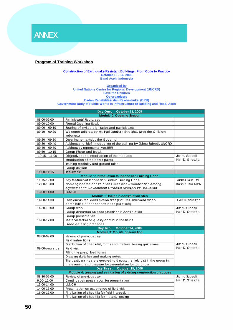
Program of Training Workshop
Construction of Earthquake Resistant Buildings: From Code to Practice
October 13 - 16, 2008 Band Aceh, Indonesia
Organized by
United Nations Centre for Regional Development (UNCRD) Save the Children
Co-organizers Badan Rehabilitasi dan Rekonstruksi (BRR)
Government Body of Public Works in Infrastructure of Building and Road, Aceh
Day One, October 13, 2008 Module 0: Opening Session
08:00-09:00 Participants' Registration 09:00-10:00 Formal Opening Session 09:00 – 09:10 Seating of invited dignitaries and participants 09:10 – 09:20 Welcome address by Mr. Hari Darshan Shrestha, Save the Children
Indonesia
09:20 – 09:30 Opening remarks by the Governor 09:30 – 09:40 Address and Brief Introduction of the training by Jishnu Subedi, UNCRD 09:40 – 09:50 Address by representatives BRR 09:50 – 10:15 Group Photo and Break 10:15 – 11:00 Objectives and introduction of the modules Introduction of the participants Training modality and ground rules
Jishnu Subedi, Hari D. Shrestha
Group division 11:00-11:15 Tea-Break
Module 1: Introduction to Indonesian Building Code 11:15-12:00 Key features of Indonesian Seismic Building Code Yuskar Lase PhD 12:00-13:00 Non-engineered construction Guidelines –Coordination among
Agencies and Government Offices in Disaster Risk Reduction Kasru Susilo MPA
13:00-14:00 LUNCH Module 2: Issues in construction sites
14:00-14:30 Problems in real construction sites (Pictures, slides and video compilation of poor construction practices)
Hari D. Shrestha
14:30-16:00 Group work Group discussion on poor practices in construction Group presentation 16:00-17:00 Material tests and quality control in the fields
Jishnu Subedi, Hari D. Shrestha
Good detailing practices Day Two, October 14, 2008 Module 3: On-site observation
08:00-09:00 Review of previous day Field instructions Distribution of check-list, forms and material testing guidelines 09:00-onwards Field visit Filling the prescribed forms Drawing sketches and making notes The participants are expected to discuss the field visit in the group in
the evening and prepare for presentation for tomorrow
Jishnu Subedi, Hari D. Shrestha
Day Three, October 15, 2008 Module 4: Lessons and evaluation of existing construction practices
08:30-09:00 Review of previous day 9:00- 12:00 Continuation preparation for presentation 13:00-14:00 LUNCH 14:00-16:00 Presentation on experience of field visit 16:00-17:00 Finalization of checklist for field inspection Finalization of checklist for material testing
Jishnu Subedi, Hari D. Shrestha
ANNEX
50

Day Four, October 16, 2008 Module 5: Vulnerability assessment and retrofitting
08:30-09:00 Review of previous day 9:00-10:00 Simple vulnerability analysis methodology 10:00-11:00 Group practice on vulnerability methodology and discussion on the
procedure
Jishnu Subedi/ Kasru Susilo
11:00-12:00 Review of vulnerability analysis methodology Jishnu Subedi 12:00-13:00 Retrofitting – Assessment, design and construction method Hari D. Shrestha 13:00-14:00 LUNCH 14:00-15:00 Continue Retrofitting Hari D. Shrestha /
Jishnu Subedi Module 6: The way forward, evaluation and closing
15:00-16:00 The way forward and approaches 16:00-17:00 Evaluation and Closing
Kasru Susilo, Hari D. Shrestha, J. Subedi
Evaluation form
Training workshop Construction of Earthquake Resistant Buildings: From Code to Practice
Evaluation Sheet
SN Achievements 1 2 3 4
Ratings Remarks SN Descriptions 8 6 4 2 0
1 Topics covered in the Training 2 Presentation of the resource persons 3 Interaction in between the participants 4 Group-work of the participants 5 Field study 6 Presentation of the participants 7 Training venue and management 8 Training program as a whole See extra sheets for additional comment
51
Editors:
Jishnu Subedi Hari Darshan Shrestha
Design and layout: Hayato Nakamura
Editorial Advice Delivered by: Shoichi Ando
Cover pictures: Front: Earthquake and Aftermath in Aceh / Java Back: Some extracts from the training workshop on “Buildings: From Code to Practice” on October 13-16, 2008 in Banda Aceh