Embed Size (px)
Citation preview

World Housing Encyclopedia an Encyclopedia of Housing Construction in
Seismically Active Areas of the World
an initiative of Earthquake Engineering Research Institute (EERI) and
International Association for Earthquake Engineering (IAEE)
HOUSING REPORT Confined block masonry building
Report # 7
Report Date 05-06-2002
Country CHILE
Housing Type Confined Masonry Building
Housing Sub-Type Confined Masonry Building with Concrete blocks, tie-columns and beams
Author(s) Ofelia Moroni, Cristian Gomez, Maximiliano Astroza
Reviewer(s) Sergio Alcocer
Important This encyclopedia contains information contributed by various earthquake engineering professionalsaround the world. All opinions, findings, conclusions & recommendations expressed herein are those of thevarious participants, and do not necessarily reflect the views of the Earthquake Engineering ResearchInstitute, the International Association for Earthquake Engineering, the Engineering InformationFoundation, John A. Martin & Associates, Inc. or the participants' organizations.
Summary
This construction practice started during the 1940s after the 1939 earthquake that struck themid-southern region of Chile. It is mainly used for dwellings and apartment buildings up tofour stories high. Buildings of this type are found in all regions of Chile. This is a confinedmasonry construction, consisting of load-bearing unreinforced masonry walls (commonly madeof clay units or concrete blocks) confined with cast-in-place reinforced-concrete, vertical tie-

columns. these tie-columns are built at regular intervals and are connected with reinforcedconcrete tie- beams cast after the masonry walls have been constructed. Tie-columns and tie-beams prevent damage due to out-of-plane bending effects and improve wall ductility. Floorsystems generally consist of cast-in-place reinforced slabs with a thickness between 100 to 120mm. Confined masonry walls have limited shear strength and ductility compared to reinforcedconcrete walls. Nevertheless, typical buildings of this type have good earthquake resistance,because they have high wall densities and because wall layouts are symmetric and regular,both in plan and elevation. Their seismic behavior has been satisfactory, particularly in one- ortwo-story-high buildings during strong earthquakes [Monge, 1969].
1. General InformationBuildings of this construction type can be found in This housing type is used all over Chile. This type of housingconstruction is commonly found in both rural and urban areas. This construction type has been in practice for lessthan 100 years.
Currently, this type of construction is being built. Most of the data in this form refers to 3-4 story buildings for lowincome people, but this housing type is also used in fancy houses due to its reasonable cost and good isolationcharacteristics.
Figure 1A: Typical building
Figure 1B: Typical building
2. Architectura l Aspects
2.1 Siting These buildings are typically found in flat terrain. They do not share common walls with adjacent buildings. Thetypical separation distance between buildings is 10 meters Buildings of this type are located close together, conformingwhat is called "conjuntos", "poblaciones" or "villas". They represent several buildings of the same type with some freespace left for garden or communities activities that most of the time nobody cares about them, ending filled withgarbage or at most, as an earth soccer field When separated from adjacent buildings, the typical distance from a
neighboring building is 10 meters.
2.2 Building Configuration The typical shape of a building plan is rectangular. In social buildings, in each longitudinal, there may be 3 to 4openings of 0.8 to 1.5 m wide, probably equally spaced. In the transverse direction there may be one or two openingsin each facade and a solid median wall.
2.3 Functional Planning The main function of this building typology is multi-family housing. In a typical building of this type, there are no

elevators and 1-2 fire-protected exit staircases. If single-story building, there is an additional door besides the main
entry. If more than one floor, there is no additional exit stair besides the main stairs.
2.4 Modification to Building Typical modification patterns observed are infill balconies.
Figure 2A: Plan of a typical building
Figure 2B: Plan of a typical building
3. Structura l Deta ils
3.1 Structura l System Materia l Type of Load-Bearing Structure # Subtypes Most appropriate type
Masonry
Stone Masonry Walls
1Rubble stone (field stone) in mud/lime mortar or w ithout mortar (usually w ith timber roof)
☐
2 Dressed stone masonry (inlime/cement mortar) ☐
Adobe/ Earthen Walls
3 Mud w alls ☐4 Mud w alls w ith horizontal w ood elements ☐5 Adobe block w alls ☐6 Rammed earth/Pise construction ☐
Unreinforced masonryw alls
7 Brick masonry in mud/limemortar ☐
8 Brick masonry in mud/limemortar w ith vertical posts ☐
9 Brick masonry in lime/cementmortar ☐
10 Concrete block masonry incement mortar ☐
Confined masonry
11 Clay brick/tile masonry, w ithw ooden posts and beams ☐
12Clay brick masonry, w ithconcrete posts/tie columnsand beams
☐
13 Concrete blocks, tie columnsand beams ☑
14 Stone masonry in cementmortar ☐
Clay brick masonry in cement
Reinforced masonry 15 mortar ☐
16Concrete block masonry incement mortar ☐
Structural concrete
Moment resistingframe
17 Flat slab structure ☐18 Designed for gravity loads
only, w ith URM infill w alls ☐
19 Designed for seismic effects,w ith URM infill w alls ☐
20 Designed for seismic effects,w ith structural infill w alls ☐
21 Dual system – Frame w ithshear w all ☐
Structural w all22 Moment frame w ith in-situ
shear w alls ☐
23 Moment frame w ith precastshear w alls ☐
Precast concrete
24 Moment frame ☐25 Prestressed moment frame
w ith shear w alls ☐26 Large panel precast w alls ☐27 Shear w all structure w ith
w alls cast-in-situ ☐
28 Shear w all structure w ithprecast w all panel structure ☐
Steel
Moment-resistingframe
29 With brick masonry partitions ☐30 With cast in-situ concrete
w alls ☐31 With lightw eight partitions ☐
Braced frame32 Concentric connections in all
panels ☐
33 Eccentric connections in afew panels ☐
Structural w all34 Bolted plate ☐35 Welded plate ☐
Timber Load-bearing timberframe
36 Thatch ☐37 Walls w ith bamboo/reed mesh
and post (Wattle and Daub) ☐
38Masonry w ith horizontalbeams/planks at intermediatelevels
☐
39 Post and beam frame (nospecial connections) ☐
40 Wood frame (w ith specialconnections) ☐
41Stud-w all frame w ithplyw ood/gypsum boardsheathing
☐
42 Wooden panel w alls ☐
OtherSeismic protection systems
43 Building protected w ith base-isolation systems ☐44 Building protected w ith
seismic dampers ☐Hybrid systems 45 other (described below ) ☐
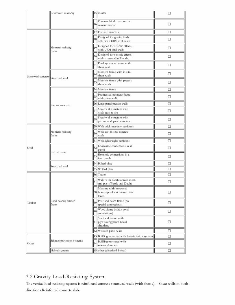
3.2 Gravity Load-Resisting System The vertical load-resisting system is reinforced concrete structural walls (with frame). Shear walls in both
directions.Reinforced concrete slab.
3.3 Latera l Load-Resisting System The lateral load-resisting system is confined masonry wall system. This is a confined masonry construction,consisting of load-bearing unreinforced masonry walls (commonly made of clay units or concrete blocks) confinedwith cast-in-place reinforced- concrete vertical tie-columns. These tie-columns are built at regular intervals and areconnected with reinforced concrete tie-beams cast after the construction of masonry walls. Tie-columns and tie- beamsprevent damage due to out-of-plane bending effects and improve wall ductility. Tie- columns have a rectangularsection whose dimensions typically correspond to the wall thickness (150 to 200 mm) and a depth equal to 200 mm.Both tie-columns and tie-beams have minimum four 10 mm diameter longitudinal reinforcement bars and 6 mmdiameter stirrups spaced at 100 to 200 mm on centre. The tie-columns have the longitudinal reinforcement necessaryto resist overturning moments. Tie-columns and tie-beams prevent damage due to out-of-plane bending effects andimprove wall ductility. When any dimension in the building pl an is longer than 20 m, reinforced concrete walls at least1 m long must be located at each end to avoid cracking in walls due to shrinkage of reinforced concrete elements asslabs and beams. Floor systems generally consist of cast-in-place reinforced slabs with a thickness between 100 to 120mm. Allowable stress method (working stress design) is used for design according to NCh2123.Of97.
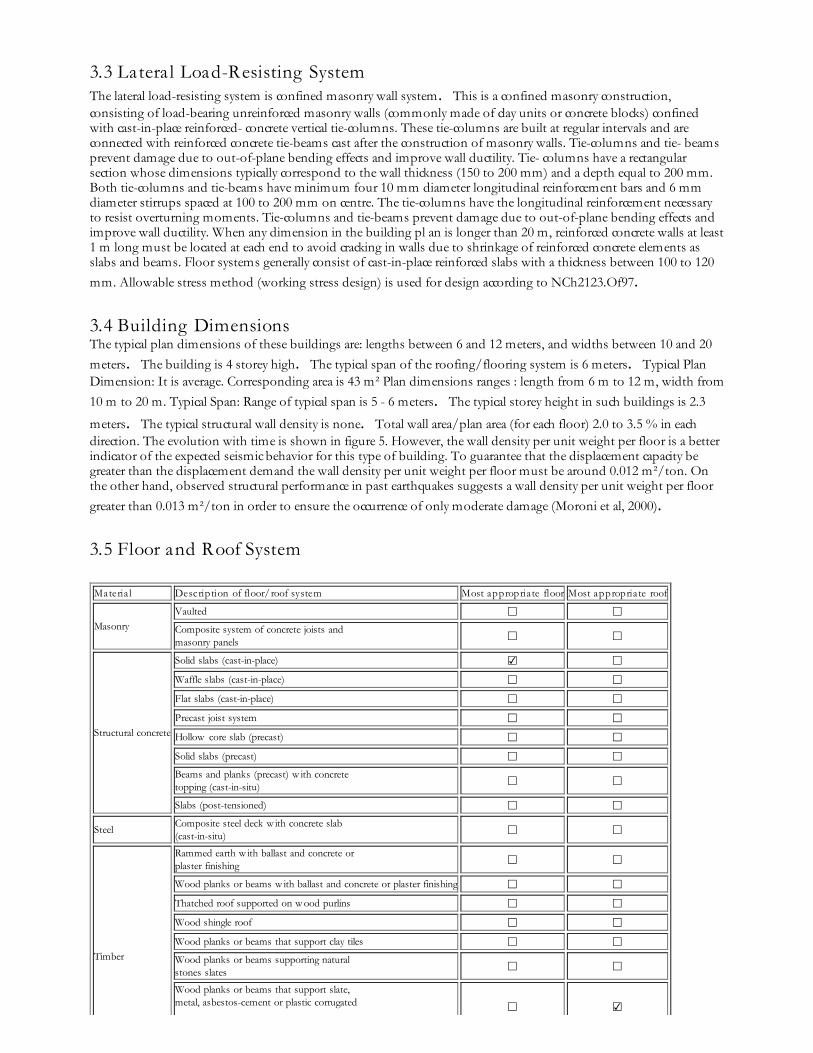
3.4 Building Dimensions The typical plan dimensions of these buildings are: lengths between 6 and 12 meters, and widths between 10 and 20meters. The building is 4 storey high. The typical span of the roofing/flooring system is 6 meters. Typical PlanDimension: It is average. Corresponding area is 43 m² Plan dimensions ranges : length from 6 m to 12 m, width from10 m to 20 m. Typical Span: Range of typical span is 5 - 6 meters. The typical storey height in such buildings is 2.3
meters. The typical structural wall density is none. Total wall area/plan area (for each floor) 2.0 to 3.5 % in eachdirection. The evolution with time is shown in figure 5. However, the wall density per unit weight per floor is a betterindicator of the expected seismic behavior for this type of building. To guarantee that the displacement capacity begreater than the displacement demand the wall density per unit weight per floor must be around 0.012 m²/ton. Onthe other hand, observed structural performance in past earthquakes suggests a wall density per unit weight per floorgreater than 0.013 m²/ton in order to ensure the occurrence of only moderate damage (Moroni et al, 2000).
3.5 Floor and Roof System
Materia l Description of floor/roof system Most appropriate floor Most appropriate roof
MasonryVaulted ☐ ☐Composite system of concrete joists andmasonry panels ☐ ☐
Structural concrete
Solid slabs (cast-in-place) ☑ ☐Waffle slabs (cast-in-place) ☐ ☐Flat slabs (cast-in-place) ☐ ☐Precast joist system ☐ ☐Hollow core slab (precast) ☐ ☐Solid slabs (precast) ☐ ☐Beams and planks (precast) w ith concretetopping (cast-in-situ) ☐ ☐Slabs (post-tensioned) ☐ ☐
Steel Composite steel deck w ith concrete slab(cast-in-situ) ☐ ☐
Timber
Rammed earth w ith ballast and concrete orplaster finishing ☐ ☐Wood planks or beams w ith ballast and concrete or plaster finishing ☐ ☐Thatched roof supported on w ood purlins ☐ ☐Wood shingle roof ☐ ☐Wood planks or beams that support clay tiles ☐ ☐Wood planks or beams supporting naturalstones slates ☐ ☐Wood planks or beams that support slate,metal, asbestos-cement or plastic corrugated ☐ ☑

sheets or tiles
Wood plank, plyw ood or manufactured w oodpanels on joists supported by beams or w alls ☐ ☐
Other Described below ☑ ☑
In the analysis the floor is considered to be a rigid diaphragm.
3.6 Foundation
Type Description Most appropriate type
Shallow foundation
Wall or column embedded insoil, w ithout footing ☐Rubble stone, fieldstoneisolated footing ☐Rubble stone, fieldstone stripfooting ☐Reinforced-concrete isolatedfooting ☐Reinforced-concrete stripfooting ☑Mat foundation ☐No foundation ☐
Deep foundation
Reinforced-concrete bearingpiles ☐Reinforced-concrete skinfriction piles ☐Steel bearing piles ☐Steel skin friction piles ☐Wood piles ☐Cast-in-place concrete piers ☐Caissons ☐
Other Described below ☐
Usually the foundation does not have reinforcement, unless the soil is clay or silt.
Figure 3: Key load-bearing elements
Figure 4: Critical structural details: w all section,foundations, roof-w all connections
Figure 5: Key seismic feature: large w all density.(The chart illustrates the variation of w all density
over time related to this construction type.)
4. Socio-Economic Aspects
4.1 Number of H ousing Units and Inhabitants Each building typically has 1 housing unit(s). 8 units in each building. Buildings may be from 1 to 4 floors. One-floorhouses may be isolated or grouping up to 4 units. Two floor houses may be isolated or grouping up to 8 units. Up to6 units per floor may exist in taller buildings. The number of inhabitants in a building during the day or businesshours is less than 5. The number of inhabitants during the evening and night is less than 5. At present, the averagesize of a family is 5.5 persons, so if one unit is occupied by up to 3 families, the number of inhabitants in a buildingmay be quite high.
4.2 Patterns of Occupancy Typically, one family occupies one housing unit. However, poor families may shelter 1 or 2 families more called"allegados".
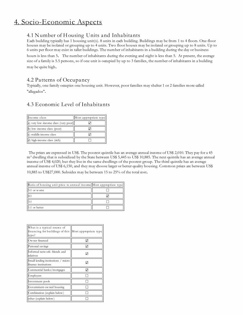
4.3 Economic Level of Inhabitants
Income class Most appropriate type
a) very low -income class (very poor) ☑b) low -income class (poor) ☑c) middle-income class ☑d) high-income class (rich) ☐
The prices are expressed in US$. The poorest quintile has an average annual income of US$ 2,010. They pay for a 45m² dwelling that is subsidized by the State between US$ 5,445 to US$ 10,885. The next quintile has an average annualincome of US$ 4,020, but they live in the same dwellings of the poorest group. The third quintile has an averageannual income of US$ 6,150, and they may choose larger or better quality housing. Common prices are between US$10,885 to US$27,000. Subsides may be between 15 to 25% of the total cost.
Ratio of housing unit price to annual income Most appropriate type
5:1 or w orse ☐4:1 ☑3:1 ☐1:1 or better ☐
What is a typica l source offinancing for bu ildings of thistype?
Most appropriate type
Ow ner financed ☑Personal savings ☑Informal netw ork: friends andrelatives ☑Small lending institutions / micro-finance institutions ☑Commercial banks/mortgages ☑Employers ☐Investment pools ☐Government-ow ned housing ☐Combination (explain below ) ☐other (explain below ) ☐

In the following typical funding modes are presented: # House type 1: Total cost: 320 UF, $ 5,000,000 (US$ 8,700)saving: 13 UF, $ 203,000 (US$ 355) subside: 140 UF, $ 2,200,000 (US$ 3,810) mortgage: 167 UF, $ 2,613,000 (US$4,545) monthly payment: 1.67UF (12 years), $26,000 (US$45,5) # House type 2: Total cost: 400 UF, $6,260,000 (US$10,885) saving: 20 UF, $ 313,000 (US$ 545) subside: 140 UF, $ 2,200,000 (US$ 3,810) mortgage: 100 UF, $ 1,565,000(US$ 2,720) monthly payment: 1.18 UF (20 years), $18,500 (US$ 32) # House type 3: Total cost: 650 UF, $10,172,500(US$ 17,690) saving: 50 UF, $ 782,500 (US$ 1,360) subside: 120 UF, $ 1,878,000 (US$ 3,265) mortgage: 480 UF, $7,512,000 (US$ 13,065) monthly payment: 4.8 UF (20 years), $75,100 (US$ 130) These calculations were done in April2001 and considered $580 = US$1.0. By October 31, 2001 $720 = US$1.0. In each housing unit, there are 1
bathroom(s) without toilet(s), no toilet(s) only and no bathroom(s) including toilet(s).
4.4 Ownership The type of ownership or occupancy is renting, outright ownership and ownership with debt (mortgage or other).
Type of ownership oroccupancy? Most appropriate type
Renting ☑outright ow nership ☑Ow nership w ith debt (mortgageor other) ☑Individual ow nership ☐Ow nership by a group or pool ofpersons ☐Long-term lease ☐other (explain below ) ☐
5. Seismic Vulnerability
5.1 Structura l and Architectura l Features Structura l/Architectura lFeature
StatementMost appropriate type
True False N/A
Lateral load path
The structure contains a complete load path for seismicforce effects from any horizontal direction that servesto transfer inertial forces from the building to thefoundation.
☑ ☐ ☐
BuildingConfiguration
The building is regular w ith regards to both the planand the elevation. ☑ ☐ ☐
Roof construction
The roof diaphragm is considered to be rigid and it isexpected that the roof structure w ill maintain itsintegrity, i.e. shape and form, during an earthquake ofintensity expected in this area.
☐ ☑ ☐
Floor construction
The floor diaphragm(s) are considered to be rigid and itis expected that the floor structure(s) w ill maintain itsintegrity during an earthquake of intensity expected inthis area.
☑ ☐ ☐
Foundationperformance
There is no evidence of excessive foundation movement(e.g. settlement) that w ould affect the integrity orperformance of the structure in an earthquake.
☑ ☐ ☐
Wall and framestructures-redundancy
The number of lines of w alls or frames in each principaldirection is greater than or equal to 2. ☑ ☐ ☐
Wall proportions
Height-to-thickness ratio of the shear w alls at each floor level is:
Less than 25 (concrete w alls);☑

Less than 30 (reinforced masonry w alls);
Less than 13 (unreinforced masonry w alls);
☐ ☐
Foundation-w allconnection
Vertical load-bearing elements (columns, w alls)are attached to the foundations; concretecolumns and w alls are dow eled into thefoundation.
☑ ☐ ☐
Wall-roofconnections
Exterior w alls are anchored for out-of-plane seismiceffects at each diaphragm level w ith metal anchors orstraps
☐ ☐ ☑
Wall openings
The total w idth of door and w indow openings in a w allis:
For brick masonry construction in cement mortar : lessthan ½ of the distance betw een the adjacent crossw alls;
For adobe masonry, stone masonry and brick masonryin mud mortar: less than 1/3 of the distance betw eenthe adjacent crossw alls;
For precast concrete w all structures: less than 3/4 ofthe length of a perimeter w all.
☑ ☐ ☐
Quality of buildingmaterials
Quality of building materials is considered to beadequate per the requirements of national codes andstandards (an estimate).
☑ ☐ ☐
Quality of w orkmanshipQuality of w orkmanship (based on visual inspection offew typical buildings) is considered to be good (perlocal construction standards).
☑ ☐ ☐
MaintenanceBuildings of this type are generally w ell maintained and thereare no visible signs of deterioration of buildingelements (concrete, steel, timber)
☐ ☑ ☐
Additional Comments Usually the roof is made of w ood planks or beams that support slate, metal, asbestos-cement or plastic corrugated sheetsor tiles.
5.2 Seismic Features Structura lElement Seismic Deficiency Earthquake Resilient
FeaturesEarthquake DamagePatterns
Wall Limited shear strength, so it is difficult to attain a flexural ductile failure.Limited ductility. Lack of tie-columns at all opening sides diminishes shearstrength and the post-shear cracking displacement capacity. Excessivespacing betw een tie-columns or lack of tie-beams may cause out-of-planedamages. Shear cracks propagate through the tie-columns reducingstiffness and strength capacity; to prevent these effects closer stirrups
should be used at column ends.
High w all density, confinementof the masonry, closer stirrupsat the tie-column and tie-beamsends. This type of buildings hasproved to have a goodearthquake resistance since 1939Chilean earthquake.
In-plane shear failure, out ofplane bending failure, lack ofbond betw een masonry andconcrete elements, damage incolumn-beam joints, damagein the connection of
perpendicular w alls. Frame(columns,beams)
Roof andfloors
5.3 Overall Seismic Vulnerability Rating The overall rating of the seismic vulnerability of the housing type is E: LOW VULNERABILITY (i.e., very good seismicperformance), the lower bound (i.e., the worst possible) is D: MEDIUM-LOW VULNERABILITY (i.e., good seismic
performance), and the upper bound (i.e., the best possible) is F: VERY LOW VULNERABILITY (i.e., excellent
seismic performance).
Vulnerability high medium-high medium medium-low low very low
very poor poor moderate good very good excellent
VulnerabilityClass
A B C D E F
☐ ☐ ☐ ☑ ☐ ☑
5.4 H istory of Past Earthquakes Date Epicenter, region Magnitude Max. Intensity
1939 Chillán, VIII Region 7.8 X (MMI) 1965 La Ligua, V Region 7.5 VIII-IX (MMI) 1985 Llolleo, V Region 7.8 VIII (MMI)
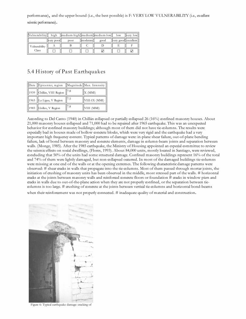
According to Del Canto (1940) in Chillán collapsed or partially collapsed 26 (16%) confined masonry houses. About21,000 masonry houses collapsed and 71,000 had to be repaired after 1965 earthquake. This was an unexpectedbehavior for confined masonry buildings; although most of them did not have tie-columns. The results wereespecially bad in houses made of hollow concrete blocks, which were very rigid and the earthquake had a veryimportant high frequency content. Typical patterns of damage were: in-plane shear failure, out-of-plane bendingfailure, lack of bond between masonry and concrete elements, damage in column-beam joints and separation betweenwalls. (Monge, 1985). After the 1985 earthquake, the Ministry of Housing appointed an especial committee to reviewthe seismic effects on social dwellings, (Flores, 1993). About 84,000 units, mostly located in Santiago, were reviewed,concluding that 50% of the units had some structural damage. Confined masonry buildings represent 16% of the totaland 74% of them were lightly damaged, but non-collapsed occurred. In most of the damaged buildings tie-columnswere missing at one end of the walls or at the opening extremes. The following characteristic damage patterns wereobserved: # shear cracks in walls that propagate into the tie-columns. Most of them passed through mortar joints, theinitiation of crushing of masonry units has been observed in the middle, most stressed part of the walls. # horizontalcracks at the joints between masonry walls and reinforced concrete floors or foundation # cracks in window piers andcracks in walls due to out-of-the-plane action when they are not properly confined, or the separation between tie-columns is too large. # crushing of concrete at the joints between vertical tie-columns and horizontal bond-beamswhen their reinforcement was not properly connected. # inadequate quality of material and construction.
Figure 6: Typical earthquake damage: cracking of

concrete posts (1985 Liolleo earthquake)
Figure 6B: Typical earthquake damage: cracking ofconcrete posts and masonry w alls (1985 Llolleo
earthquake)Figure 6C: Typical earthquake damage: collapse of a
confined w all ( 1985 Llolleo earthquake)
Figure 6D: Typical earthquake damage: cracking ofmasonry w alls (1985 Llolleo earthquake)
6. Construction
6.1 Building Materia ls
Structura lelement Bu ilding materia l Characteristic
strengthMixproportions/dimensions Comments
Walls Artisan brick Clay hollow brickconcrete block mortar.
2-8 MPa 6-12 MPa 3-10 MPa 10 MPa.
20 X 30 cm 14 X 29 cm 39 X19 cm 1:1/4/4 (mix)
absorption: 15-40% 10-20% 5-12%masonryshear strength= 0.5 to 1.0 MPa
Foundation
Frames (beams& columns) Concrete H-18 Steel A44-28H 18 - 20 MPa 280 MPa
Roof andfloor(s)
6.2 Builder No information is available .
6.3 Construction Process, Problems and Phasing One contractor builds large quantities of this type of buildings, so project management and control techniques areused in order to increase productivity and to diminish cost. With respect to equipment the following is commonlyused: concrete mix, trucks, traveling crane, winch. Tie-columns are cast against serrated endings of the masonry walls

already built. After that tie- beams, lintels and slab are built simultaneously. The construction of this type of housing
takes place in a single phase. Typically, the building is originally designed for its final constructed size.
6.4 Design and Construction Expertise The structural engineer will have 6 years of studies and more than 3-5 years of experience. The construction engineermay have 6 years of studies and less experience than the structural engineer. There is not compulsory inspection duringthe construction and no peer revision of the structural project, but when inspection does exist larger masonrycompression strength are allowed. The designer may visit the construction site once or twice during the construction.
6.5 Building Codes and Standards This construction type is addressed by the codes/standards of the country. NCh2123.Of97 Albañilería Confinada-requisitos para el diseño y cálculo. Until 1993, the NCh433.of72 and "Ordenanza General de Construcciones yUrbanización" were in force. The latter since 1949 regulated the construction of 1 or 2 story confined masonry houses,limiting the maximum spacing between tie-columns and tie-beams. In general these buildings are quite stiff, theymust resist a base shear of 10-22% depending on the seismic zone and the story drift must be equal or less than 0.002.The NCh2123 code specifies the allowable shear capacity of a confined masonry wall based on the masonry shear stressand the vertical load applied on it; the size and the minimum quantity of longitudinal reinforcement and amount andspacing of stirrups that must be used in confinement elements; limits wall thickness, tie-column spacing, requiresconfinement in opening, among others dispositions. The year the first code/standard addressing this type of
construction issued was 1949. NCh433.Of96, Diseño sísmico de Edificios. The most recent code/standard
addressing this construction type issued was 1997. Title of the code or standard: NCh2123.Of97 AlbañileríaConfinada-requisitos para el diseño y cálculo. Until 1993, the NCh433.of72 and "Ordenanza General deConstrucciones y Urbanización" were in force. The latter since 1949 regulated the construction of 1 or 2 story confinedmasonry houses, limiting the maximum spacing between tie-columns and tie-beams. In general these buildings arequite stiff, they must resist a base shear of 10-22% depending on the seismic zone and the story drift must be equal orless than 0.002. The NCh2123 code specifies the allowable shear capacity of a confined masonry wall based on themasonry shear stress and the vertical load applied on it; the size and the minimum quantity of longitudinalreinforcement and amount and spacing of stirrups that must be used in confinement elements; limits wall thickness,tie-column spacing, requires confinement in opening, among others dispositions. Year the first code/standardaddressing this type of construction issued: 1949 National building code, material codes and seismic codes/standards:NCh433.Of96, Diseño sísmico de Edificios When was the most recent code/standard addressing this constructiontype issued? 1997.
The building design must follow the NCh433.of96 code and NCh2123.of97. SERVIU a governmental office in chargeof social dwellings has a professional staff to review the projects and to inspect during construction. In case of damagea panel of experts process may take place at the court of justice.
6.6 Building Permits and Development Control Rules This type of construction is a non-engineered, and not authorized as per development control rules. Building
permits are required to build this housing type.
6.7 Building Maintenance Typically, the building of this housing type is maintained by Owner(s), Tenant(s) , No one and others.
6.8 Construction Economics 5-12 UF/m² (135-300 US$/m²). At present, depending on technology used, the construction of several units,
simultaneously built, may take 2-3 stories per month.
7. Insurance

Earthquake insurance for this construction type is typically available. For seismically strengthened existing buildingsor new buildings incorporating seismically resilient features, an insurance premium discount or more completecoverage is unavailable. Earthquake insurance is available as supplement of other insurance (fire, robbery) and peopleliving in these buildings do not have money to pay for that, although mortgage payment includes this type ofinsurance. Repair cost.
8. Strengthening
8.1 Description of Seismic Strengthening Provisions
Strengthening of Existing Construction :Seismic Deficiency Description of Seismic Strengthening provisions used
Partially confinement New tie-columns are built
Most of the damage that have occurred in confined masonry buildings was due to lack of confinement in some edgeor opening, so the strengthening procedure has consisted on completing the confinement of the masonry wall withreinforced concrete tie-column. If the wall was extensively damaged a new wall has been constructed or coated withshotcrete over a wire mesh anchored to the masonry. With this procedure ductility is also improved. When only somebricks have been damaged, they have been replaced; the same occurred when cracks appeared in the mortar joints. Thismay cost up to 7-8 % of the original cost.
8.2 Seismic Strengthening Adopted
Has seismic strengthening described in the above table been performed in design and construction practice, and if so,to what extent? As it was pointed out in 6.1, after the 1985 earthquake a committee was appointed by the Ministry of Housing, inorder to review the damaged buildings, to prepare restoration projects and supervise its execution. Most of thestrengthening consisted on tie-columns additions and repair of cracks in masonry walls.
Was the work done as a mitigation effort on an undamaged building, or as repair following an earthquake? Repair following earthquake damage.
8.3 Construction and Performance of Seismic Strengthening
Was the construction inspected in the same manner as the new construction? Yes.
Who performed the construction seismic retrofit measures: a contractor, or owner/user? Was an architect or engineerinvolved? A contractor, an engineer was involved.
What was the performance of retrofitted buildings of this type in subsequent earthquakes? There has not been any earthquake in Central Chile since 1985. Page 18.
Reference(s)1. Construcciones de Alba
M. Astroza and F. DelfCap 5 del libro "El sismo de Marzo de 1985, Chile," (Ed) J. Monge 1985
2. Edificios de albaM. AstrozaCap 15 del libro "Ingenier 1993
3. Apuntes de Curso: CI 52-H. DiseM. AstrozaDivisi 2000
4. DaR. FloresCap 15 del libro "Ingenier 1993
5. CaracterJ. GiadalahCivil Engineer Thesis, Universidad de Chile 2000
6. DiseINN NCh 433 of 96
7. AlbaINN NCh2123 of 97
8. Seismic behavior and design of small buildings in ChileJ. MongeProc. 4WCEE, Santiago, Chile, Vol VI, B-6, pp 1-9 1969
9. "Regulaciones sismorresistentes",J. MongeCap 4 del libro "El sismo de Marzo de 1985, Chile, (Ed.) J. Monge 1985
10. Wall density and seismic performance of confined masonry buildingsM. Moroni, M. Astroza and R. CaballeroTMS Journal, July 2000, pp 81-88 2000
Author(s)1. Ofelia Moroni
Civil Engineer/Assistant Professor, University of ChileCasilla 228/3, Santiago , CHILEEmail:[email protected] FAX: 562-6892833
2. Cristian GomezCivil Engineer/Research Assistant, University of ChileCasilla 228/3, Santiago 228/3, CHILEEmail:[email protected] FAX: 562-6892833
3. Maximiliano AstrozaCivil Engineer/ Associate Professor, University of ChileCasilla 228/3, Santiago , CHILEEmail:[email protected] FAX: 562-6892833
Reviewer(s)1. Sergio Alcocer
Director of Research

Circuito Escolar Cuidad Universitaria, Institute of Engineering, UNAMMexico DF 4510, MEXICOEmail:[email protected] FAX: +52 (55) 56162894
Save page as