Embed Size (px)
Citation preview

Article
Hot Press Joining Optimization of Polyethylene to Aluminium Alloy AA6061-T6 Lap Joint Using Design of Experiments Sabah Khammass Hussein1,a,*, Abdulmuhssan N. Mhessan2,b, and Mustafa Ahmed Alwan1,c
1 Engineering Technical College, Middle Technical University, Baghdad, Iraq
2 Middle Technical University, Baghdad, Iraq
E-mail: [email protected] (Corresponding author), [email protected], [email protected]
Abstract. The hot press method is used to join a poly-ethylene plate of thickness 4 mm with an aluminium alloy AA6061-T6 plate of thickness 1.5 mm. A preanodizing process is crucial for the success of such joint. The anodizing was performed under a current density of 200 A/m2, temperature 24°C, sulphuric acid 5 wt. % and for a 60 minutes. Three period parameters were considered in the hot pressing process; temperature: 115 and 135°C, pressure: 2, 6, and 10 bar and pressing time: 1, 2, 3, 4 and 5 minutes. The joint specimens are tested by shear tensile test, microstructure, energy dispersive spectrometry, differential scanning calorimetric and thermo grvanometric analysis. The results of shear tensile were analyzed using design of experiments. Minimum and maximum shear tensile force were found at temperature T = 115°C where; F min = 680N and F max = 2800N. From Pareto chart, the applied pressure had the most significant effect on the shear tensile force of the joint specimens compared to temperature and joining time. The main effect plot showed that optimum value of shear tensile force was obtained at joining conditions of T = 135°C, P = 6 bar and t = 3 minutes. The tested specimens exhibited an interfacial shear failure, extension and necking in the region of polymer with a ductile fracture. The mechanical interlocking of polymer element in the anodizing surface is approximately 15 µm. The melting point and glass transmission temperature of PE are decreased after the hot press.
Keywords: Hot press join, welding, anodizing, DOE, poly-ethylene.
ENGINEERING JOURNAL Volume 21 Issue 7 Received 5 January 2017 Accepted 3 May 2017 Published 29 December 2017 Online at http://www.engj.org/ DOI:10.4186/ej.2017.21.7.157

DOI:10.4186/ej.2017.21.7.157
158 ENGINEERING JOURNAL Volume 21 Issue 7, ISSN 0125-8281 (http://www.engj.org/)
1. Introduction Reducing weight and CO2 emission are important in vehicles and structure industries [1–6], which in turn reduces the cost of manufacturing, fuel used in vehicles operation and improve its performance. Achieving such objections requires the replacement of some structural parts with other having smaller weight and superior mechanical properties. Studies related to this subject investigated polymers and composite materials. At the present time polymers become equivalent to most of the engineering materials [7]. Polymers have higher stiffness to weight ratio, mechanical strength, corrosion, electrical and thermal insulation.
Modern joining processes include friction spot [8], ultrasonic metal welding [9] and laser direct [10], and hot pressing [11]. The improvement of the adhesive bonding properties in hybrid structure was the interest of some studies [12, 13]. Manufacturers invested in higher stiffness, durability as well as light weight segments which are widely used in aircrafts, automotive, and electronic industries [14, 15]. Metal and polymer joining is difficult because of differences in mechanical and physical characteristics [16]. Techniques for joining lightweight dissimilar materials, particularly metals and polymers, are becoming increasingly important in the manufacturing of hybrid structures and components for engineering applications [17].
The hybrid polyamide-aluminium structure has been joined by a novel laser beam process. Pre-treatment of the aluminium surface by electro-chemical or laser has special effect on the shear strength of the joint [18]. Friction lap welding (FLW) has been demonstrated on aluminium alloy AA6061 and MC Nylon-6. A linear relationship is observed between welding parameters and the thickness of the melted nylon. The influences of those parameters on formulated bubbles and shear strength were examined. The shear fractured surface is classified to seven different regions [19]. Fatigue tests were executed to predicate the fatigue performance of a Glass Fibre reinforced Polyamide with aluminium joint for self-piercing riveting process. The influence of welding process parameters and environmental factors on the fatigue behaviour of joint performances was inspected. The rivet shape has a small influence on the joint fatigue strength as varied with the temperature [20]. A fiber laser joint is used to adhere the aluminium alloy A6061 with carbon fibre reinforce plastic. A phosphate anodizing has been done on the surface of aluminium samples. The results showed that the anodizing process strengthened the joint [21]. Dissimilar joints of zinc-coated steel and carbon fibre reinforced plastics (CFRPs) using continuous wave (CW) diode laser is performed. Formed bubbles inside the melted zone of CFRP were found [22]. A2017P was bounded with three types of glass-fiber-reinforced plastic (GFRP). The adhesive–embossing joining tended to compete the fabrication of lightweight GFRP-metal hybrid structures [23]. The adhesion models and the effect of surface treatments of AlMg3-CF/PA66-joints are described. Single-lap joints presented a characterization of the bonding mechanisms and the influence of the surface treatments. The previous described test series showed that the pre-treatment of the metallic joining partner by corundum blasting and the application of additional polymer in the joining zone have positive influence on the shear tensile strength [24]. A join of metal (steel DC01 and aluminium AlMg3) and CFRPC (organic sheets CF-PA66 and CF-PEEK) is developed by means of induction heating. Basic experiments on the influence of pre-treatments and process parameters showed great influence of corundum blasting, acidic pickling and temperature control on the shear tensile strength. Joints shear tensile strength of 14.5MPa for AlMg3/CF-PA66 and of 20MPa for DC01/CF-PEEK, respectively was measured [25]. A novel approach for thermal joining of thermoplastic metal hybrids by means of a combination of mono- and polychromatic radiation was presented. The influences of laser structuring of the metal surface on the joint connections were investigated. Additionally, climate tests according to BMW PR 308.2 in temperature range -30 - 90°C and from -40 -120°C were performed to analyze the long-term durability of the hybrid joint connections [26]. The polymer is heated up to temperatures above the melting temperature. The thermoplastic is pressed under a definite force to the heated metal. The thermoplastic melts are close to its surface and wets the metal. After this, the joint is cooled under pressure. The results presented that the high tensile-shear strengths up to 25 MPa was observed in a short term overlap shear tests for a combinations of aluminium or steel with polyamide 6, with 30% wt. [27].
Studies of hot press join of poly-ethylene with aluminium alloy (AA6061-T6) are limited, especially in the case of the anodized surface of the aluminium alloy. The present work objective is to study the effect of the hot press process parameters; pressure, temperature and time on the mechanical properties of the joint the hybrid lap joint (Polyethylene and AA6061-T6). An anodizing method with a special solution was introduced in the Aluminium samples. The shear force of the hybrid lap joint was optimised using the design of experiments method.

DOI:10.4186/ej.2017.21.7.157
ENGINEERING JOURNAL Volume 21 Issue 7, ISSN 0125-8281 (http://www.engj.org/) 159
2. Experimental Setup 2.1. Materials Two types of materials are used in hot press join; aluminium alloy 6061-T6 and polyethylene (PE), melting point Tm=139°C. The chemical and mechanical properties of aluminium alloy are presented in Tables 1 and 2, respectively.
Table 1. Chemical composition of AA6061-T6.
Elements wt% Si Fe Cu Mn Mg Cr Zn Ti
0.593 0.405 0.231 0.102 0. 87 0.180 0.021 0.056
Table 2. Mechanical properties of AA6061-T6.
Tensile strength (MPa) Yield strength (MPa) Elongation (%)
348 245 11.5
2.2. Specimens Preparation Samples of the polymer (PE) are prepared from a sheet of thickness (4 mm), while the thickness of aluminium alloy (AA6061-T6) samples is (1.5 mm). All specimens are prepared according to the standard specification (AWS spot welding C1.1M/C1.1:2012) with dimensions of (length =100 mm, width = 25 mm) as shown in Fig. 1. The lap joint is assembled such that its dimensions are (25 x 25 mm2).
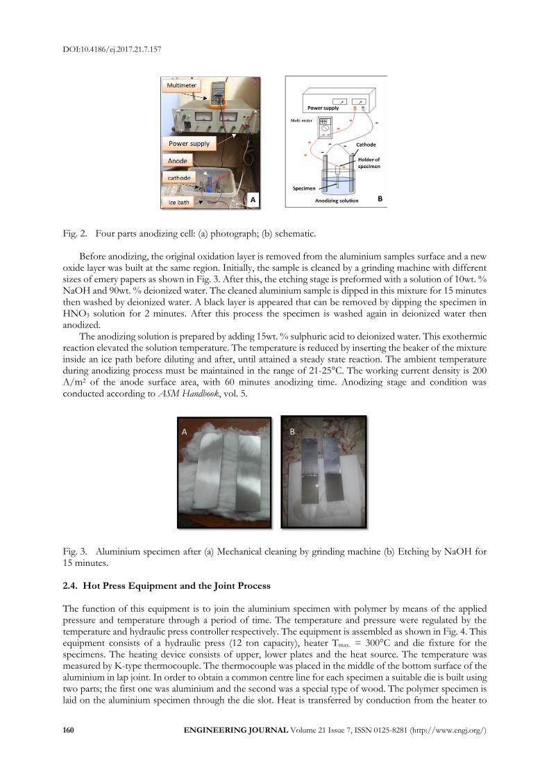
Fig. 1. Schematic of an aluminium/ polymer with lap joint of 25 X 25 mm2. 2.3. The Anodizing Process The anodizing cell was assembled as shown in Fig. 2. The power supply produces a uniform DC current. In order to check the accuracy, an auto range digital multi-meter with 3 digits was used to measure the electrolyte cell current. In order to increase the anodizing process, the Lead material is used as cathode due to its higher density as compared with the anodizing material. The cathode surface area is three times the anode surface area and gives higher electron transmission density and uniform anodizing surface layer.
DOI:10.4186/ej.2017.21.7.157
160 ENGINEERING JOURNAL Volume 21 Issue 7, ISSN 0125-8281 (http://www.engj.org/)
Fig. 2. Four parts anodizing cell: (a) photograph; (b) schematic.
Before anodizing, the original oxidation layer is removed from the aluminium samples surface and a new oxide layer was built at the same region. Initially, the sample is cleaned by a grinding machine with different sizes of emery papers as shown in Fig. 3. After this, the etching stage is preformed with a solution of 10wt. % NaOH and 90wt. % deionized water. The cleaned aluminium sample is dipped in this mixture for 15 minutes then washed by deionized water. A black layer is appeared that can be removed by dipping the specimen in HNO3 solution for 2 minutes. After this process the specimen is washed again in deionized water then anodized.
The anodizing solution is prepared by adding 15wt. % sulphuric acid to deionized water. This exothermic reaction elevated the solution temperature. The temperature is reduced by inserting the beaker of the mixture inside an ice path before diluting and after, until attained a steady state reaction. The ambient temperature during anodizing process must be maintained in the range of 21-25°C. The working current density is 200 A/m2 of the anode surface area, with 60 minutes anodizing time. Anodizing stage and condition was conducted according to ASM Handbook, vol. 5.
Fig. 3. Aluminium specimen after (a) Mechanical cleaning by grinding machine (b) Etching by NaOH for 15 minutes. 2.4. Hot Press Equipment and the Joint Process The function of this equipment is to join the aluminium specimen with polymer by means of the applied pressure and temperature through a period of time. The temperature and pressure were regulated by the temperature and hydraulic press controller respectively. The equipment is assembled as shown in Fig. 4. This equipment consists of a hydraulic press (12 ton capacity), heater Tmax. = 300°C and die fixture for the specimens. The heating device consists of upper, lower plates and the heat source. The temperature was measured by K-type thermocouple. The thermocouple was placed in the middle of the bottom surface of the aluminium in lap joint. In order to obtain a common centre line for each specimen a suitable die is built using two parts; the first one was aluminium and the second was a special type of wood. The polymer specimen is laid on the aluminium specimen through the die slot. Heat is transferred by conduction from the heater to

DOI:10.4186/ej.2017.21.7.157
ENGINEERING JOURNAL Volume 21 Issue 7, ISSN 0125-8281 (http://www.engj.org/) 161
the aluminium specimen through the aluminium part of this die. The polymer specimen is pressed on the anodized layer of the aluminium specimen.
Fig. 4. Schematic of the hot press assembly.
The main hot press variables are; temperature, pressure and time. The temperature was chosen to be 115 and 135°C while the pressure is varied between three values 2, 6 and 10 bar. The pressing time was 1, 2, 3, 4 or 5 minutes. The design of experiment was used with 30 different conditions to analyze the effect of these parameters. Figure 5 presents the joint specimens.
Fig. 5. Experimental joint specimens of PE-AL. 2.5. Experimental Tests The joint specimens were tested by shear, microstructure, energy dispersive spectrometry (EDS) and differential scanning calorimetric (DSC) test.
The standard “AWS spot welding C1.1M/C1.1:2012” was adopted in the tensile shear test. In order to prevent slipping and bending during the tensile test, a shim is placed at the ends of each specimen in the opposite sides as in Fig. 6(a). The cross head velocity of the tensile shear test is 1mm/minute.
Thermal analysis of the interlocked part between polymer and aluminium during the hot press joints was carried out in order to evaluate the local physicochemical changes using (DSC) test, as shown Fig. 6(c). The crystals analysis, melting behaviour, decomposition and thermal degradation resulting from the hot press process of (PE) were examined.
In the microstructure test, the specimens are dealt with by wet grinding using SIC papers with different ASTM grits (600, 800, 1000, 1200 and 2000). The grinding, polishing and processes are done with different particle size of alumina (3, 0.3, and 0.05). A special cloth is used at 200 RPM. The mirror was obtained by washing with water and alcohol.
To analyze the microstructure details and estimate the percentage of elemental distribution by means of (EDS) map line scan analysis, scanning electron microscope model (TESCAN) was used as shown in Fig. 6(b).

DOI:10.4186/ej.2017.21.7.157
162 ENGINEERING JOURNAL Volume 21 Issue 7, ISSN 0125-8281 (http://www.engj.org/)
The microstructure and EDS analysis was performed in the cross section (a-a) of the joint, as shown in Fig. 7. The anodizing process is electrochemical cell and therefor the regular anodizing layer is found mostly at the middle of the joint area (section a-a).
Fig. 6. Experimental tests equipment: (a) Shear tensile; (b) SEM,EDS analysis; (c) DSC analysis.
Fig. 7. Cross section joint of microstructure and EDS.
The design of experiment method is used to optimize the processing parameters. The experimental predicted optimum value of shear force is calculated from the following relation [28]:
𝜇 = 𝜇𝑚 + ∑ (�̅�𝑖 − 𝜇𝑚)𝑛𝑖=1 (1)
where:
μ : The predicted shear force using optimum level of the hot press welding;
μm : Total mean of shear force;
μ̅i : mean of shear force at the optimum value; n : The number of mean hot press parameters that significantly affect the performance ( affect the shear force results);
The above equation is used to predict the optimum value. The particular levels of the predicted optimum value are used in the experiments to obtain the optimum value.
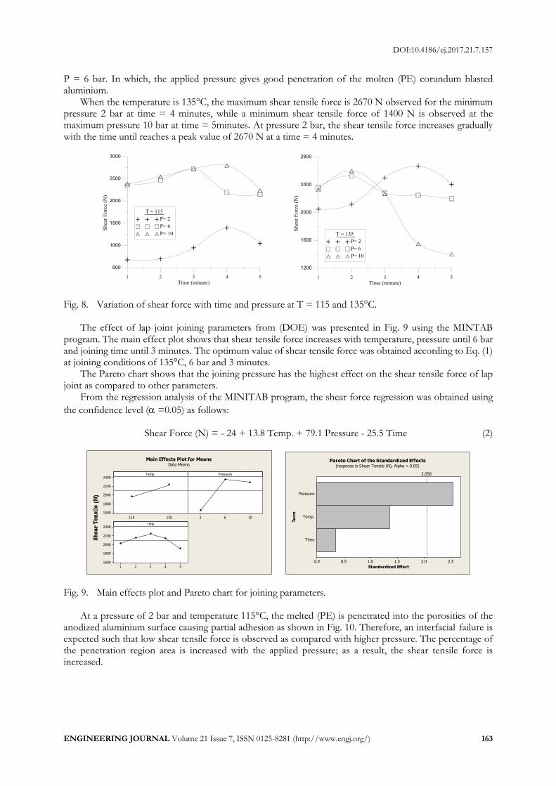
3. Results 3.1. Shear Tensile Test The entire 30 specimens were successfully jointed and tested under shear tensile force. For the first level of temperature 115°C as shown in Fig. 8, the minimum and maximum shear tensile force values are observed. At a minimum applied pressure of 2 bar and time of 1 minute, Fmin was found to be 680 N at a maximum applied pressure of 10 bar and time of 4 minutes, Fmax was 2800N. The minimum shear tensile force was observed in the minimum joining conditions, thus, the amount of the applied pressure and time are not enough to give a complete penetration of the molten (PE) into the anodized surface of aluminium and vice versa. Under the maximum shear tensile force, The shear tensile force increases gradually with time until reaching its maximum value at a specific time = 4 minutes for P = 2 and 10 bar and at time = 3 minutes for
DOI:10.4186/ej.2017.21.7.157
ENGINEERING JOURNAL Volume 21 Issue 7, ISSN 0125-8281 (http://www.engj.org/) 163
P = 6 bar. In which, the applied pressure gives good penetration of the molten (PE) corundum blasted aluminium.
When the temperature is 135°C, the maximum shear tensile force is 2670 N observed for the minimum pressure 2 bar at time = 4 minutes, while a minimum shear tensile force of 1400 N is observed at the maximum pressure 10 bar at time = 5minutes. At pressure 2 bar, the shear tensile force increases gradually with the time until reaches a peak value of 2670 N at a time = 4 minutes.
Fig. 8. Variation of shear force with time and pressure at T = 115 and 135°C.
The effect of lap joint joining parameters from (DOE) was presented in Fig. 9 using the MINTAB program. The main effect plot shows that shear tensile force increases with temperature, pressure until 6 bar and joining time until 3 minutes. The optimum value of shear tensile force was obtained according to Eq. (1) at joining conditions of 135°C, 6 bar and 3 minutes.
The Pareto chart shows that the joining pressure has the highest effect on the shear tensile force of lap joint as compared to other parameters.
From the regression analysis of the MINITAB program, the shear force regression was obtained using
the confidence level ( =0.05) as follows: Shear Force (N) = - 24 + 13.8 Temp. + 79.1 Pressure - 25.5 Time (2)
Fig. 9. Main effects plot and Pareto chart for joining parameters.
At a pressure of 2 bar and temperature 115°C, the melted (PE) is penetrated into the porosities of the anodized aluminium surface causing partial adhesion as shown in Fig. 10. Therefore, an interfacial failure is expected such that low shear tensile force is observed as compared with higher pressure. The percentage of the penetration region area is increased with the applied pressure; as a result, the shear tensile force is increased.
135115
2400
2200
2000
1800
1600
1062
54321
2400
2200
2000
1800
1600
Temp.
Shea
r Ten
sile
(N)
Pressure
Time
Main Effects Plot for MeansData Means
Time
Temp.
Pressure
2.52.01.51.00.50.0
Te
rm
Standardized Effect
2.056
Pareto Chart of the Standardized Effects(response is Shear Tensile (N), Alpha = 0.05)

DOI:10.4186/ej.2017.21.7.157
164 ENGINEERING JOURNAL Volume 21 Issue 7, ISSN 0125-8281 (http://www.engj.org/)
Fig. 10. Interfacial failure in shear tensile test at T = 115°C.
Higher joining temperature of 135°C results in higher penetration area of PE in the surface of the aluminium samples resulting in higher shear tensile force. Figure 11 presents the fracture surface of some samples. A ductile failure with an extension and necking at the polymer region is observed for an optimum shear tensile force Fmax = 2800N as shown in Fig. 12. The weakest material (polymer) of the lap joint failed in the form of necking without shearing the bounded area therefore the maximum shear force of the interlocking material reached its peak value as shown in Fig. 12.
Fig. 11. Interfacial failure in shear tensile test at T = 135°C.
Fig. 12. Extension and necking at the polymer region. 3.2. Scanning Electron Microscope and Optical Microscope Test During anodizing, the old oxide layer is removed and a new symmetric layer redeveloped which enhances the wetting between the molten polymer and aluminium surface. The porosity clearly appears through wide regions in the surface area as shown in Fig. 13.
DOI:10.4186/ej.2017.21.7.157
ENGINEERING JOURNAL Volume 21 Issue 7, ISSN 0125-8281 (http://www.engj.org/) 165
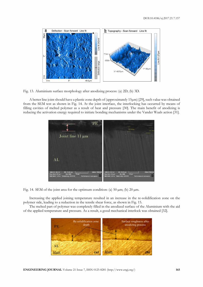
Fig. 13. Aluminium surface morphology after anodizing process: (a) 2D; (b) 3D.
A better line joint should have a plastic zone depth of (approximately 15μm) [29], such value was obtained from the SEM test as shown in Fig. 14. At the joint interface, the interlocking has occurred by means of filling cavities of melted polymer as a result of heat and pressure [30]. The main benefit of anodizing is reducing the activation energy required to initiate bonding mechanisms under the Vander Waals action [31].
Fig. 14. SEM of the joint area for the optimum condition: (a) 50 µm; (b) 20 µm.
Increasing the applied joining temperature resulted in an increase in the re-solidification zone on the polymer side, leading to a reduction in the tensile shear force, as shown in Fig. 15.
The melted part of polymer was completely filled in the anodized surface of the Aluminium with the aid of the applied temperature and pressure. As a result, a good mechanical interlock was obtained [32].
DOI:10.4186/ej.2017.21.7.157
166 ENGINEERING JOURNAL Volume 21 Issue 7, ISSN 0125-8281 (http://www.engj.org/)
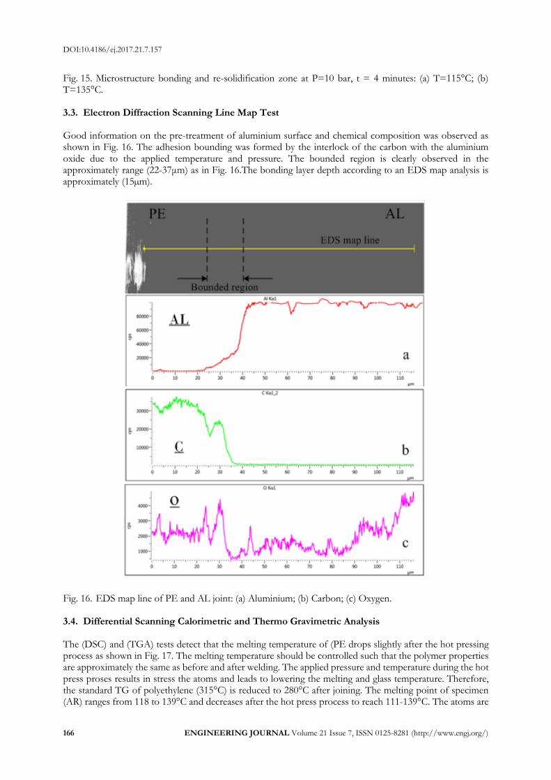
Fig. 15. Microstructure bonding and re-solidification zone at P=10 bar, t = 4 minutes: (a) T=115°C; (b) T=135°C. 3.3. Electron Diffraction Scanning Line Map Test Good information on the pre-treatment of aluminium surface and chemical composition was observed as shown in Fig. 16. The adhesion bounding was formed by the interlock of the carbon with the aluminium oxide due to the applied temperature and pressure. The bounded region is clearly observed in the approximately range (22-37μm) as in Fig. 16.The bonding layer depth according to an EDS map analysis is approximately (15µm).
Fig. 16. EDS map line of PE and AL joint: (a) Aluminium; (b) Carbon; (c) Oxygen. 3.4. Differential Scanning Calorimetric and Thermo Gravimetric Analysis The (DSC) and (TGA) tests detect that the melting temperature of (PE drops slightly after the hot pressing process as shown in Fig. 17. The melting temperature should be controlled such that the polymer properties are approximately the same as before and after welding. The applied pressure and temperature during the hot press proses results in stress the atoms and leads to lowering the melting and glass temperature. Therefore, the standard TG of polyethylene (315°C) is reduced to 280°C after joining. The melting point of specimen (AR) ranges from 118 to 139°C and decreases after the hot press process to reach 111-139°C. The atoms are

DOI:10.4186/ej.2017.21.7.157
ENGINEERING JOURNAL Volume 21 Issue 7, ISSN 0125-8281 (http://www.engj.org/) 167
affected by pressure and temperature, which stressed them and as a result, they need lower temperature to transform from solid to a molten state. Polymer is composed of long and short chains. Polymer properties are changed when these chains affected. Long chains need high energy to be affected compared to short ones [33]. The applied pressure and temperature during the welding process led to the decomposition of the short chains and a change in polymer properties. As a result, the TG and rel. mass change (%) have been decreased.
The relf. mass change (%) of polyethylene was initially increased until reach the steady state and then decreased gradually as shown in Fig. 17(a). In The welded joint, this percentage was decreased with steady state Due to the applied pressure and temperature as shown in Fig. 17(b). After achieved the hot press process, there was no changes in the mass of specimens.
Fig. 17. DSC & TGA chart of (PE) (a) Before weld (b) After weld.
4. Conclusions Lap joints between Polyethylene and AA6061 aluminium alloy were produced by hot press welding technique. The influence of welding parameters; pressure, time and temperature on the shear force of lap joint was investigated. The results can be summarized as follows:

DOI:10.4186/ej.2017.21.7.157
168 ENGINEERING JOURNAL Volume 21 Issue 7, ISSN 0125-8281 (http://www.engj.org/)
(1) The shear force of the hot press lap joint was depended on the joining parameters; time, pressure and temperature.
(2) The optimum joining parameter that produce maximum shear force of 2800 N were; a temperature of 115°C, a pressure of 10 bar and a holding time of 4 minutes.
(3) Sufficient levels of welding parameters increases lap joint shear tensile force and the penetration of polymer into the anodized surface.
(4) The pressure has the highest effect on the shear tensile force of lap joint, while, the welding time has the lowest effect.
(5) The common failure type in hot pressing of Al-PE was a lap joint interfacial failure. (6) The specimen of optimum shears exhibit extension and necking in polymer. (7) The molten polymer element interlock is approximately (15 µm).
References [1] Z. Huang, S. Sugiyama, and J. Yanagimoto, “Adhesive–embossing hybrid joining process to fiber-
reinforced thermosetting plastic and metallic thin sheets,” Procedia Engineering, vol. 81, pp. 2123-2128, 2014.
[2] H. Adam, “Carbon fibre in automotive applications,” Mater. Des., vol. 18, pp. 349–55, 1997. [3] P. Beardmore and C. F. Johnson, “The potential for composites in structural automotive applications,”
Composites science and Technology, vol. 26, no. 4, pp. 251-281, 1986. [4] K. L. Edwards, “An overview of the technology of fibre-reinforced plastics for design purposes,”
Materials & Design, vol. 19, no. 1, pp. 1-10, 1998. [5] L. Ye, Y. Lu, Z. Su, and G. Meng, “Functionalized composite structures for new generation airframes:
A review,” Composites Science and Technology, vol. 65, no. 9, pp. 1436-1446, 2005. [6] J. C. Williams and E. A. Starke, “Progress in structural materials for aerospace systems,” Acta Materialia,
vol. 51, no. 19, pp. 5775-5799, 2003. [7] B. Klein, Leichtbau-Konstruktion: Berechnungsgrundlagen und Gestaltung, (German edition). Springer-Verlag,
2013 [8] S. T. Amancio-Filho, C. Bueno, J. F. Dos Santos, N. Huber, and E. Hage, “On the feasibility of friction
spot joining in magnesium/fiber-reinforced polymer composite hybrid structures,” Materials Science and Engineering: A, vol. 528, no. 10, pp. 3841-3848, 2011.
[9] F. Balle, G. Wagner, and D. Eifler, “Ultrasonic metal welding of aluminium sheets to carbon fibre
reinforced thermoplastic composites,” Advanced Engineering Materials, vol. 11, no. 1‐2, pp. 35-39, 2009. [10] S. Katayama and Y Kawahito, “Laser direct joining of metal and plastic,” Scripta Materialia, vol. 59, no.
12, pp. 1247-1250, 2008. [11] D. J. Park, H. G. Kim, J. Y. Park, Y. I. Jung, J. H. Park, and Y. H. Koo, “FeCrAl and Zr alloys joined
using hot isostatic pressing for fusion energy applications,” Fusion Engineering and Design, vol. 109, pp. 561-564, 2016.
[12] G. Kelly, “Joining of carbon fibre reinforced plastics for automotive applications,” doctoral dissertation, Department of Aeronautical and Vehicle Engineering, Royal Institute of Tchnology, Stockholm, Sweden, 2004.
[13] W. Michaeli and W. M. Hoffmann, “Hybride Verbindungen,” Kunststoffe, vol. 6, pp. 50–53, 2009. [14] C.-J. Lee, J.-M. Lee, H.-Y. Ryu, K.-H. Lee, B.-M. Kim, and D.-C. Ko, “Design of hole-clinching process
for joining of dissimilar materials–Al6061-T4 alloy with DP780 steel, hot-pressed 22MnB5 steel, and carbon fiber reinforced plastic,” Journal of Materials Processing Technology, vol. 214, no. 10, pp. 2169-2178, 2014.
[15] R. W. Messler, “Joining composite materials and structures: Some thought-provoking possibilities,” Journal of Thermoplastic Composite Materials, vol. 17, no. 1, pp. 51-75, 2004.
[16] S. T. Amancio‐Filho and J. F. Dos Santos. “Joining of polymers and polymer–metal hybrid structures: Recent developments and trends,” Polymer Engineering & Science, vol. 49, no. 8, pp. 1461-1476, 2009.
[17] P. Kah, R. Suoranta, J. Martikainen, and C. Magnus, “Techniques for joining dissimilar materials: Metals and polymers,” Rev. Adv. Mater. Sci, vol. 36, pp. 152-164, 2014.
[18] C. Lamberti, T. Solchenbach, P. Plapper, and W. Possart, “Laser assisted joining of hybrid polyamide-aluminum structures,” Physics Procedia, vol. 56, pp. 845-853, 2014.
DOI:10.4186/ej.2017.21.7.157
ENGINEERING JOURNAL Volume 21 Issue 7, ISSN 0125-8281 (http://www.engj.org/) 169
[19] F. C. Liu, J. Liao, and K. Nakata, “Joining of metal to plastic using friction lap welding,” Materials & Design, vol. 54, pp. 236-244, 2014.
[20] A. Gay, F. Lefebvre, S. Bergamo, F. Valiorgue, P. Chalandon, P. Michel, and P. Bertrand, “Fatigue of aluminum/glass fiber reinforced polymer composite assembly joined by self-piercing riveting,” Procedia Engineering, vol. 133, pp. 501-507, 2015.
[21] Z. Zhang, J.-G. Shan, X.-H. Tan, and J. Zhang, “Effect of anodizing pretreatment on laser joining CFRP to aluminum alloy A6061,” International Journal of Adhesion and Adhesives, vol. 70, pp. 142-151, 2016.
[22] K. W. Jung, Y. Kawahito, M. Takahashi, and S. Katayama. “Laser direct joining of carbon fiber reinforced plastic to zinc-coated steel,” Materials & Design, vol. 47, pp. 179-188, 2013.
[23] Z. Huang, S. Sugiyama, and J. Yanagimoto, “Applicability of adhesive–embossing hybrid joining process to glass-fiber-reinforced plastic and metallic thin sheets,” Journal of Materials Processing Technology, vol. 214, no. 10, pp. 2018-2028, 2014.
[24] P. Mitschang, R. Velthuis, and M. Didi, “Induction spot welding of metal/CFRPC hybrid joints,” Advanced Engineering Materials, vol. 15, no. 9, pp. 804-813, 2013.
[25] M. Carboni and M. Annoni, “Ultrasonic metal welding of AA 6022‐T4 lap joints: Part II–fatigue behaviour, failure analysis and modelling,” Science and Technology of Welding and Joining, vol. 16, no. 2, pp. 116-125, 2011.
[26] E. Haberstroh and M. Sickert, “Thermal direct joining of hybrid plastic metal components,” King Mongkut’s University of Technology North Bangkok International Journal of Applied Science and Technology, vol. 7, no. 3, pp. 29-34, 2014.
[27] E. Rodríguez-Vidal, C. Sanz, C. Soriano, J. Leunda, and G. Verhaeghe, “Effect of metal micro-structuring on the mechanical behavior of polymer–metal laser T-joints,” Journal of Materials Processing Technology, vol. 229, pp. 668-677, 2016.
[28] D. C. Montgomery, Design and Analysis of Experiments. John Wiley & Sons, 2009. [29] L. J. Hart-Smith, “A peel-type durability test coupon to assess interfaces in bonded, co-bonded, and co-
cured composite structures,” International Journal of Adhesion and Adhesives, vol. 19, no. 2, pp. 181-191, 1999.
[30] J. P. Bergmann and M. Stambke, “Potential of laser-manufactured polymer-metal hybrid joints,” Physics Procedia, vol. 39, pp. 84-91, 2012.
[31] J. Holtkamp, A. Roesner, and A. Gillner, “Advances in hybrid laser joining,” The International Journal of Advanced Manufacturing Technology, vol. 47, no. 9-12, pp. 923-930, 2010.
[32] W. Ratanathavorn, “Hybrid joining of aluminum to thermoplastics with friction stir welding,” M.S. thesis, Department of Materials Science and Engineering, KTH-Royal Institute of Technology, Stockholm, Sweden, 2012.
[33] W. D. Callister, Jr., Materials Science and Engineering: An Introduction, 7th ed. USA: John Wiley & Sons, INC, 2007.