Embed Size (px)
Citation preview

Host/Host Protocol
for the
ARPA Network
Prepared for the Network Working Group by
Alex McKenzie
BBN
January 1972
NIC 8246 2
1/72
PREFACE
This document specifies a protocol for use in communication between Host computers on theARPA Network. In particular, it provides for connection of independent processes in different
Hosts, control of the flow of data over established connections, and several ancillary functions.Although basically self-contained, this document specifies only one of several ARPA Networkprotocols; all protocol specifications are collected in the document Current Network Protocols,
NIC #7104.
This document supercedes NIC #7147 of the same title. Principal differences between the
documents include:
• prohibition of spontaneous RET, ERP, and RRP commands
• a discussion of the problem of unanswered CLS commands (page13)
• a discussion of the implications of queueing and not queueing RPCs (page 11)
• the strong recommendation that received ERR commands be logged, and some additional
ERR specifications.
In addition to the above, several minor editorial changes have been made.
Although there are many individuals associated with the network who are knowledgeableabout protocol issues, individuals with questions pertaining to Network protocols should initially
contact one of the following:
Steve Crocker
Advanced Research Projects Agency1400 Wilson BoulevardArlington, Virginia 22209
(202) 694-5921 or 5922
Alex McKenzie
Bolt Beranek and Newman Inc.50 Moulton StreetCambridge, Massachusetts 02133(617) 491-1350 ext. 441

NIC 8246 3
1/72
Jon Postel
University of California at Los AngelesComputer Science Department3732 Boelter Hall
Los Angeles, California 90024(213) 325-2363
NIC 8246 4
1/72
TABLE OF CONTENTS
I. INTRODUCTION .................................................................................................................... 5
An overview of the multi-leveled protocol structure in the ARPA Network.
II. COMMUNICATION CONCEPTS ........................................................................................ 7
Definitions of terminology and a description of the overall strategy used in
Host-to-Host communication.
III. NCP FUNCTIONS............................................................................................................... 10
The meat of the document for the first-time reader. Host-to-Host
“commands” are introduced with descriptions of conditions of their use,
discussion of possible problems, and other background material.
Connection Establishment......................... 10
Connection Termination............................ 12Flow Control.............................................. 14Interrupts ................................................... 16
Test Inquiry ............................................... 17Reinitialization .......................................... 17
IV. DECLARATIVE SPECIFICATIONS............................................................................... 19
Details for the NCP implementer. A few additional “commands” are
introduced, and those described in Section III are reviewed. Formats and
code and link assignments are specified.
Message Format ........................................ 19Link Assignment ....................................... 21
Control Messages ...................................... 21Control Commands.................................... 21Opcode Assignment .................................. 26
Control Command Summary..................... 27
NIC 8246 5
1/72
I. INTRODUCTION
The ARPA Network provides a capability for geographically separated computers, calledHosts, to communicate with each other. The Host computers typically differ from one another in
type, speed, word length, operating system, etc. Each Host computer is connected into thenetwork through a local small computer called an Interface Message Processor (IMP). Thecomplete network is formed by interconnecting these IMPs, all of which are virtually identical,
through wideband communications lines supplied by the telephone company. Each IMP isprogrammed to store and forward messages to the neighboring IMPs in the network. During atypical operation, a Host passes a message to its local IMP; the first 32 bits of this message
include the “network address” of a destination Host. The message is passed from IMP to IMPthrough the Network until it finally arrives at the destination IMP, which in turn passes it alongto the destination Host.
Specifications for the physical and logical message transfer between a Host and its local IMPare contained in Bolt Beranek and Newman (BBN) Report No. 1822. These specifications are
generally called the first level protocol or Host/IMP Protocol. This protocol is not by itself,however, sufficient to specify meaningful communication between processes running in twodissimilar Hosts. Rather, the processes must have some agreement as to the method of initiating
communication, the interpretation of transmitted data, and so forth. Although it would bepossible for such agreements to be reached by each pair of Hosts (or processes) interested incommunication, a more general arrangement is desirable in order to minimize the amount of
implementation necessary for Network-wide communication. Accordingly, the Hostorganizations formed a Network Working Group (NWG) to facilitate an exchange of ideas and toformulate additional specifications for Host-to-Host communications.
The NWG has adopted a “layered” approach to the specification of communicationsprotocol. The inner layer is the Host/IMP protocol. The next layer specifies methods of
establishing communications paths, managing buffer space at each end of a communicationspath, and providing a method of “interrupting” a communications path. This protocol, which willbe used by all higher-level protocols, is known as the second level protocol, or Host/Host
protocol. (It is worth noting that, although the IMP sub-network provides a capability formessage switching, the Host/Host protocol is based on the concept of line switching.) Examplesof further layers of protocol currently developed or anticipated include:
NIC 8246 6
1/72
1) An Initial Connection Protocol (ICP) which provides a convenient standard method for
several processes to gain simultaneous access to some specific process (such as the“logger”) at another Host.
2) A Telecommunication Network (TELNET) protocol which provides for the “mapping” ofan arbitrary keyboard-printer terminal into a Network Virtual Terminal (NVT), tofacilitate communication between a terminal user at one Host site and a terminal-serving
process at some other site which “expects” to be connected to a (local) terminal logicallydifferent from the (remote) terminal actually in use. The TELNET protocol specifies useof the ICP to establish the communication path between the terminal user and the
terminal-service process.
3) A Data Transfer protocol to specify standard methods of formatting data for shipment
through the network.
4) A File Transfer protocol to specify methods for reading, writing, and updating files
stored at a remote Host. The File Transfer protocol specifies that the actual transmissionof data should be performed in accordance with the Data Transfer protocol.
5) A Graphics protocol to specify the means for exchanging graphics display information.
6) A Remote Job Service (RJS) protocol to specify methods for submitting input to,
obtaining output from, and exercising control over Hosts which provide batch processingfacilities.
The remainder of this document describes and specifies the Host/Host, or second level,protocol as formulated by the Network Working Group.
NIC 8246 7
1/72
II. COMMUNICATION CONCEPTS
The IMP sub-network imposes a number of physical restrictions on communications betweenHosts; these restrictions are presented in BBN Report Number 1822. In particular, the concepts
of leaders, messages, padding, links, and message types are of interest to the design of Host/Hostprotocol. The following discussion assumes that the reader is familiar with these concepts.
Although there is little uniformity among the Hosts in either hardware or operating systems,the notion of multiprogramming dominates most of the systems. These Hosts can eachconcurrently support several users, with each user running one or more processes. Many of these
processes may want to use the network concurrently, and thus a fundamental requirement of theHost/Host protocol is to provide for process-to-process communication over the network. Sincethe first level protocol only takes cognizance of Hosts, and since the several processes in
execution within a Host are usually independent, it is necessary for the second level protocol toprovide a richer addressing structure.
Another factor which influenced the Host/Host protocol design is the expectation that typicalprocess-to-process communication will be based, not on a solitary message, but rather upon asequence of messages. One example is the sending of a large body of information, such as a data
base, from one process to another. Another example is an interactive conversation between twoprocesses, with many exchanges.
These considerations led to the introduction of the notions of connections, a Network ControlProgram, a “control link”, “control commands”, connection byte size, message headers, andsockets.
A connection is an extension of a link. A connection couples two processes so that outputfrom one process is input to the other. Connections are defined to be simplex (i.e., uni-
directional), so two connections are necessary if a pair of processes are to converse in bothdirections.
Processes within a Host are envisioned as communicating with the rest of the networkthrough a Network Control Program (NCP), resident in that Host, which implements the secondlevel protocol. The primary function of the NCP is to establish connections, break connections,and control data flow over the connections. We will describe the NCP as though it were part of
NIC 8246 8
1/72
the operating system of a Host supporting multiprogramming, although the actual method of
implementing the NCP may be different in some Hosts.
In order to accomplish its tasks, the NCP of one Host must communicate with the NCPs of
other Hosts. To this end, a particular link between each pair of Hosts has been designated as thecontrol link. Messages transmitted over the control link are called control messages,* and mustalways be interpreted by an NCP as a sequence of one or more control commands. For example,
one kind of control command is used to initiate a connection, while another kind carriesnotification that a connection has been terminated.
The concept of a message, as used above, is an artifact of the IMP sub-network; networkmessage boundaries may have little intrinsic meaning to communicating processes. Accordingly,it has been decided that the NCP (rather than each transmitting process) should be responsible
for segmenting interprocess communication into network messages. Therefore, it is a principal ofthe second level protocol that no significance may be inferred from message boundaries by areceiving process. The only exception to this principle is in control messages, each of which must
contain an integral number of control commands.
Since message boundaries are selected by the transmitting NCP, the receiving NCP must be
prepared to concatenate successive messages from the network into a single (or differentlydivided) transmission for delivery to the receiving process. The fact that Hosts have differentword sizes means that a message from the network might end in the middle of a word at the
receiving end, and thus the concatenation of the next message might require the receiving Host tocarry out extensive bit-shifting. Because bit-shifting is typically very costly in terms of computerprocessing time, the protocol includes the notions of connection byte size and message headers.
As part of the process of establishing a connection, the processes involved must agree on aconnection byte size. Each message sent over the connection must then contain an integral
number of bytes of this size. Thus the pair of processes involved in a connection can choose amutually convenient byte size, for example, the least common multiple of their Host wordlengths. It is important to note that the ability to choose a byte size must be available to the
processes involved in the connection; an NCP is prohibited from imposing an arbitrary byte size
* Note that in BBN Report Number 1822, messages of non-zero type are called control messages,and are used to control the flow of information between a Host and its IMP. In this document, the
term “control message” is used for a message of type zero transmitted over the control link. TheIMPs take no special notice of these messages.

NIC 8246 9
1/72
on any process running in its own Host. In particular, an outer layer of protocol may specify a
byte size to be used by that protocol. If some NCP is unable to handle that byte size, then theouter layer of protocol will not be implementable on that Host.
The IMP sub-network requires that the first 32 bits of each message (called the leader)contain addressing information, including destination Host address and link number. The secondlevel protocol extends the required information at the beginning of each message to a total of 72
bits; these 72 bits are called the message header. A length of 72 bits is chosen since most Hostseither can work conveniently with 8-bit units of data or have word lengths of 18 or 36 bits; 72 isthe least common multiple of these lengths. Thus, the length chosen for the message header
should reduce bit-shifting problems for many Hosts. In addition to the leader, the message headerincludes a field giving the byte size used in the message, a field giving the number of bytes in themessage, and “filler” fields. The format of the message header is fully described in Section IV.
Another major concern of the second level protocol is a method for reference to processes inother Hosts. Each Host has some internal scheme for naming processes, but these various
schemes are typically different and may even be incompatible. Since it is not practical to imposea common internal process naming scheme, a standard intermediate name space is used, with aseparate portion of the name space allocated to each Host. Each Host must have the ability to
map internal process identifiers into its portion of this name space.
The elements of the name space are called sockets. A socket forms one end of a connection,
and a connection is fully specified by a pair of sockets. A socket is identified by a Host numberand a 32-bit socket number. The same 32-bit number in different Hosts represents differentsockets.
A socket is either a receive socket or a send socket, and is so marked by its low-order bit (0 =receive; 1 = send). This property is called the socket’s gender. The sockets at either end of a
connection must be of opposite gender. Except for the gender, second level protocol places noconstraints on the assignment of socket numbers within a Host.
NIC 8246 10
1/72
III. NCP FUNCTIONS
The functions of the NCP are to establish connections, terminate connections, control flow,transmit interrupts, and respond to test inquiries. These functions are explained in this section,
and control commands are introduced as needed. In Section IV the formats of all controlcommands are presented together.
Connection Establishment
The commands used to establish a connection are STR (sender-to-receiver) and RTS
(receiver- to-sender).
8* 32 32 8
STR send socket receive socket size
8 32 32 8
RTS receive socket send socket link
The STR command is sent from a prospective sender to a prospective receiver, and the RTS froma prospective receiver to a prospective sender. The send socket field names a socket local to the
prospective sender; the receive socket field names a socket local to the prospective receiver. Inthe STR command, the “size” field contains an unsigned binary number (in the range 1 to 255;zero is prohibited) specifying the byte size to be used for all messages over the connection. In the
RTS command, the “link” field specifies a link number; all messages over the connection mustbe sent over the link specified by this number. These two commands are referred to as requests-for-connection (RFCs). An STR and an RTS match if the receive socket fields match and the
send socket fields match. A connection is established when a matching pair of RFCs have beenexchanged. Hosts are prohibited from establishing more than one connection to any local socket.
With respect to a particular connection, the Host containing the send socket is called thesending Host and the Host containing the receive socket is called the receiving Host. A Host mayconnect one of its receive sockets to one of its send sockets, thus becoming both the sending
Host and the receiving Host for that connection. These terms apply only to data flow; controlmessages will, in general, be transmitted in both directions.
* The number shown above each control command field is the length of that field in bits.
NIC 8246 11
1/72
A Host sends an RFC either to request a connection, or to accept a foreign Host’s request.Since RFC commands are used both for requesting and for accepting the establishment of aconnection, it is possible for either of two cooperating processes to initiate connection
establishment. As a consequence, a family of processes may be created with connection-initiating actions built-in, and the processes within this family may be started up (in differentHosts) in arbitrary order provided that appropriate queueing is performed by the Hosts involved
(see below).
There is no prescribed lifetime for an RFC. A Host is permitted to queue incoming RFCs and
withhold a response for an arbitrarily long time, or, alternatively, to reject requests (seeConnection Termination below) immediately if it does not have a matching RFC outstanding. Itmay be reasonable, for example, for an NCP to queue an RFC that refers to some currently
unused socket until a local process takes control of that socket number and tells the NCP toaccept or reject the request. Of course, the Host which sent the RFC may be unwilling to wait foran arbitrarily long time, so it may abort the request. On the other hand, some NCP
implementations may not include any space for queueing RFCs, and thus can be expected toreject RFCs unless the RFC sequence was initiated locally.
Queueing Considerations
The decision to queue, or not queue, incoming RFCs has important implications which NCP
implementers must not ignore. Each RFC which is queued, of course, requires a small amount ofmemory in the Host doing the queueing. If each incoming RFC is queued until a local processseizes the local socket and accepts (or rejects) the RFC, but no local process ever seizes the
socket, the RFC must be queued “forever.” Theoretically this could occur infinitely many times(there is no reason not to queue several RFCs for a single local socket, letting the local processdecide which, if any, to accept) thus requiring infinite storage for the RFC queue. On the other
hand, if no queueing is performed the cooperating processes described above will be able toestablish a desired connection only by accident (when they are started up such that one issues itsRFC while the RFC of the other is in transit in the network—clearly an unlikely occurrence).
Perhaps the most reasonable solution to the problems posed above is for each NCP to giveprocesses running in its own Host two options for attempting to initiate connections. The firstoption would allow a process to cause an RFC to be sent to a specified remote socket; with the
NCP notifying the process as to whether the RFC were accepted or rejected by the remote Host.The second option would allow a process to tell its own NCP to “listen” for an RFC to a
NIC 8246 12
1/72
specified local socket from some remote socket (the process might also specify the particular
remote socket and/or Host it wishes to communicate with) and to accept the RFC (i.e., return amatching RFC) if and when it arrives. Note that this also involves queueing (of “listen”requests), but it is internal queueing which is susceptible to reasonable management by the local
Host. If this implementation were available, one of two cooperating processes could “listen”while the other process caused a series of RFCs to be sent to the “listening” socket until one wasaccepted. Thus, no queueing of incoming RFCs would be required, although it would do no
harm.
It is the intent of the protocol that each NCP should provide either the “listen” option
described above or a substantial queueing facility. This is not, however, an absolute requirementof the protocol.
Connection Termination
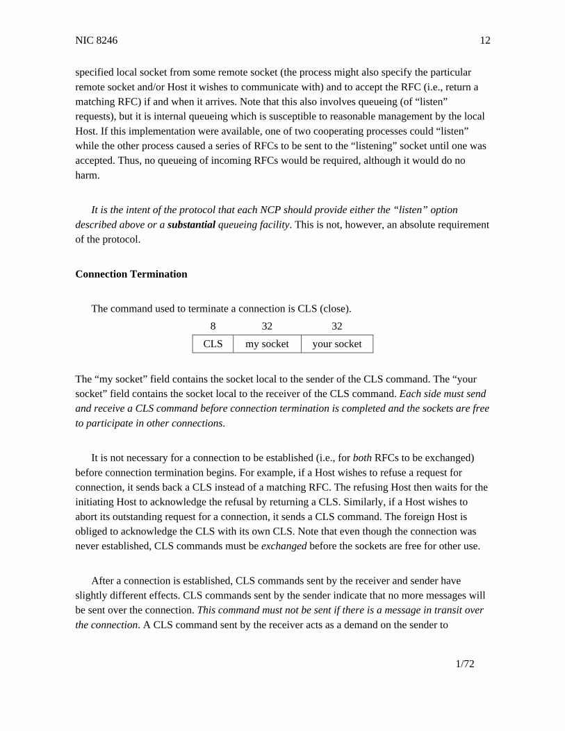
The command used to terminate a connection is CLS (close).
8 32 32
CLS my socket your socket
The “my socket” field contains the socket local to the sender of the CLS command. The “yoursocket” field contains the socket local to the receiver of the CLS command. Each side must sendand receive a CLS command before connection termination is completed and the sockets are free
to participate in other connections.
It is not necessary for a connection to be established (i.e., for both RFCs to be exchanged)
before connection termination begins. For example, if a Host wishes to refuse a request forconnection, it sends back a CLS instead of a matching RFC. The refusing Host then waits for theinitiating Host to acknowledge the refusal by returning a CLS. Similarly, if a Host wishes to
abort its outstanding request for a connection, it sends a CLS command. The foreign Host isobliged to acknowledge the CLS with its own CLS. Note that even though the connection wasnever established, CLS commands must be exchanged before the sockets are free for other use.
After a connection is established, CLS commands sent by the receiver and sender haveslightly different effects. CLS commands sent by the sender indicate that no more messages willbe sent over the connection. This command must not be sent if there is a message in transit over
the connection. A CLS command sent by the receiver acts as a demand on the sender to
NIC 8246 13
1/72
terminate transmission. However, since there is a delay in getting the CLS command to the
sender, the receiver must expect more input.
A Host should “quickly” acknowledge an incoming CLS so the foreign Host can purge its
tables. However, there is no prescribed time period in which a CLS must be acknowledged.
Because the CLS command is used both to initiate closing, aborting and refusing a
connection, and to acknowledge closing, aborting and refusing a connection, race conditions canoccur. However, they do not lead to ambiguous or erroneous results, as illustrated in thefollowing examples.
Example 1: Suppose that Host A sends Host B a request for connection, and then A sends aCLS to Host B because it is tired of waiting for a reply. However, just when A sends its CLS
to B, B sends a CLS to A to refuse the connection. A will “believe” B is acknowledging theabort, and B will “believe” A is acknowledging its refusal, but the outcome will be correct.
Example 2: Suppose that Host A sends Host B an RFC followed by a CLS as in example 1.In this case, however, B sends a matching RFC to A just when A sends its CLS. Host A may“believe” that the RFC is an attempt (on the part of B) to establish a new connection or may
understand the race condition; in either case it can discard the RFC since its socket is not yetfree. Host B will “believe” that the CLS is breaking an established connection, but theoutcome is correct since a matching CLS is the required response, and both A and B will then
terminate the connection.
Every NCP implementation is faced with the problem of what to do if a matching CLS is not
returned “quickly” by a foreign Host (i.e., if the foreign Host appears to be violating protocol inthis respect). One naive answer is to hold the connection in a partially closed state “forever”waiting for a matching CLS. There are two difficulties with this solution. First, the socket
involved may be a “scarce resource” such as the “logger” socket specified by an InitialConnection Protocol (see NIC # 7101) which the local Host cannot afford to tie up indefinitely.Second, a partially broken (or malicious) process in a foreign Host may send an unending stream
of RFCs which the local Host wishes to refuse by sending CLS commands and waiting for amatch. This could, in worst cases, require 232! socket pairs to be stored before duplicates began toappear. Clearly, no Host is prepared to store (or search) this much information.
NIC 8246 14
1/72
A second possibility sometimes suggested is for the Host which is waiting for matching CLS
commands (Host A) to send a RST (see page 17) to the offending Host (Host B), thus allowingall tables to be reinitialized at both ends. This would be rather unsatisfactory to any user at HostA who happened to be performing useful work on Host B via network connections, since these
connections would also be broken by the RST.
Most implementers, recognizing these problems, have adopted some unofficial timeout
period after which they “forget” a connection even if a matching CLS has not been received. Thedanger with such an arrangement is that if a second connection between the same pair of socketsis later established, and a CLS finally arrives for the first connection, the second connection is
likely to be closed. This situation can only arise, however, if one Host violates protocol in two
ways; first by failing to respond quickly to an incoming CLS, and second by permittingestablishment of a connection involving a socket which it believes is already in use. It has been
suggested that the network adopt some standard timeout period, but the NWG has been unable toarrive at a period which is both short enough to be useful and long enough to be acceptable toevery Host. Timeout periods in current use seem to range between approximately one minute and
approximately five minutes. It must be emphasized that all timeout periods, although they arerelatively common, reasonably safe, and quite useful, are in violation of the protocol since their
use can lead to connection ambiguities.
Flow Control
After a connection is established, the sending Host sends messages over the agreed-upon linkto the receiving Host. The receiving NCP accepts messages from its IMP and queues them for itsvarious processes. Since it may happen that the messages arrive faster than they can be
processed, some mechanism is required which permits the receiving Host to quench the flowfrom the sending Host.
The flow control mechanism requires the receiving Host to allocate buffer space for eachconnection and to notify the sending Host of how much space is available. The sending Hostkeeps track of how much room is available and never sends more data than it believes the
receiving Host can accept.
To implement this mechanism, the sending Host keeps two counters associated with eachconnection, a message counter and a bit counter. Each counter is initialized to zero when the
connection is established and is increased by allocate (ALL) control commands sent from thereceiving Host as described below. When sending a message, the NCP of the sending Host
NIC 8246 15
1/72
subtracts one from the message counter and the text length (defined below) from the bit counter.
The sender is prohibited from sending if either counter would be decremented below zero. Thesending Host may also return all or part of the message or bit space allocation with a return(RET) command upon receiving a give-back (GVB) command from the receiving Host (see
below).
The text length of a message is defined as the product of the connection byte size and the
byte count for the message; both of these quantities appear in the message header. Messages witha zero byte count, hence a zero text length, are specifically permitted. Messages with zero textlength do not use bit space allocation, but do use message space allocation. The flow control
mechanisms do not pertain to the control link, since connections are never explicitly establishedover this link.
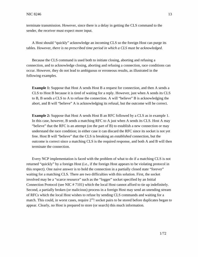
The control command used to increase the sender’s bit counter and message counter is ALL(allocate).
8 8 16 32
ALL link msg space bit space
This command is sent only from the receiving Host to the sending Host, and is legal only when a
connection using the link number appearing in the “link” field is established. The “msg space”field and the “bit space” field are defined to be unsigned binary integers specifying the amountsby which the sender’s message counter and bit counter (respectively) are to be incremented. The
receiver is prohibited from incrementing the sender’s counter above (216–1), or the sender’s bitcounter above (232–1). In general, this rule will require the receiver to maintain counters whichare incremented and decremented according to the same rules as the sender’s counters.
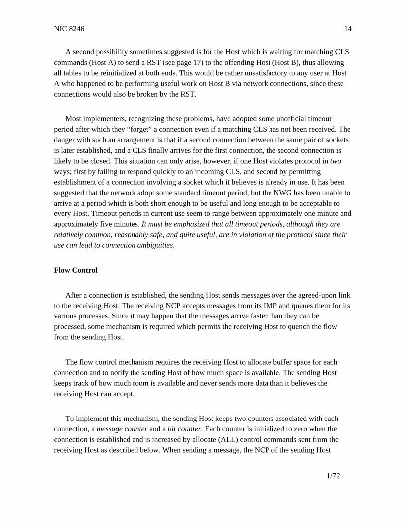
The receiving Host may request that the sending Host return all or part of its currentallocation. The control command for this request is GVB (give-back).
8 8 8 8
GVB link fm fb
This command is sent only from the receiving Host to the sending Host, and is legal only when aconnection using the link number in the “link” field is established. The fields fm and fb aredefined as the fraction (in 128ths) of the current message space allocation and bit spaceallocation (respectively) to be returned. If either of the fractions is equal to or greater than one,
NIC 8246 16
1/72
all of the corresponding allocation must be returned. Fractions are used since, with messages in
transit, the sender and receiver may not agree on the actual allocation at every point in time.
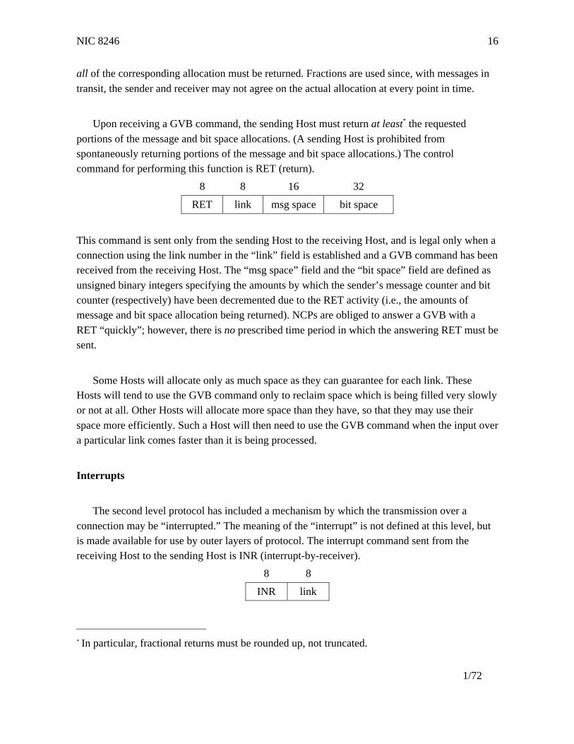
Upon receiving a GVB command, the sending Host must return at least* the requested
portions of the message and bit space allocations. (A sending Host is prohibited fromspontaneously returning portions of the message and bit space allocations.) The controlcommand for performing this function is RET (return).
8 8 16 32
RET link msg space bit space
This command is sent only from the sending Host to the receiving Host, and is legal only when aconnection using the link number in the “link” field is established and a GVB command has beenreceived from the receiving Host. The “msg space” field and the “bit space” field are defined as
unsigned binary integers specifying the amounts by which the sender’s message counter and bitcounter (respectively) have been decremented due to the RET activity (i.e., the amounts ofmessage and bit space allocation being returned). NCPs are obliged to answer a GVB with a
RET “quickly”; however, there is no prescribed time period in which the answering RET must besent.
Some Hosts will allocate only as much space as they can guarantee for each link. TheseHosts will tend to use the GVB command only to reclaim space which is being filled very slowlyor not at all. Other Hosts will allocate more space than they have, so that they may use their
space more efficiently. Such a Host will then need to use the GVB command when the input overa particular link comes faster than it is being processed.
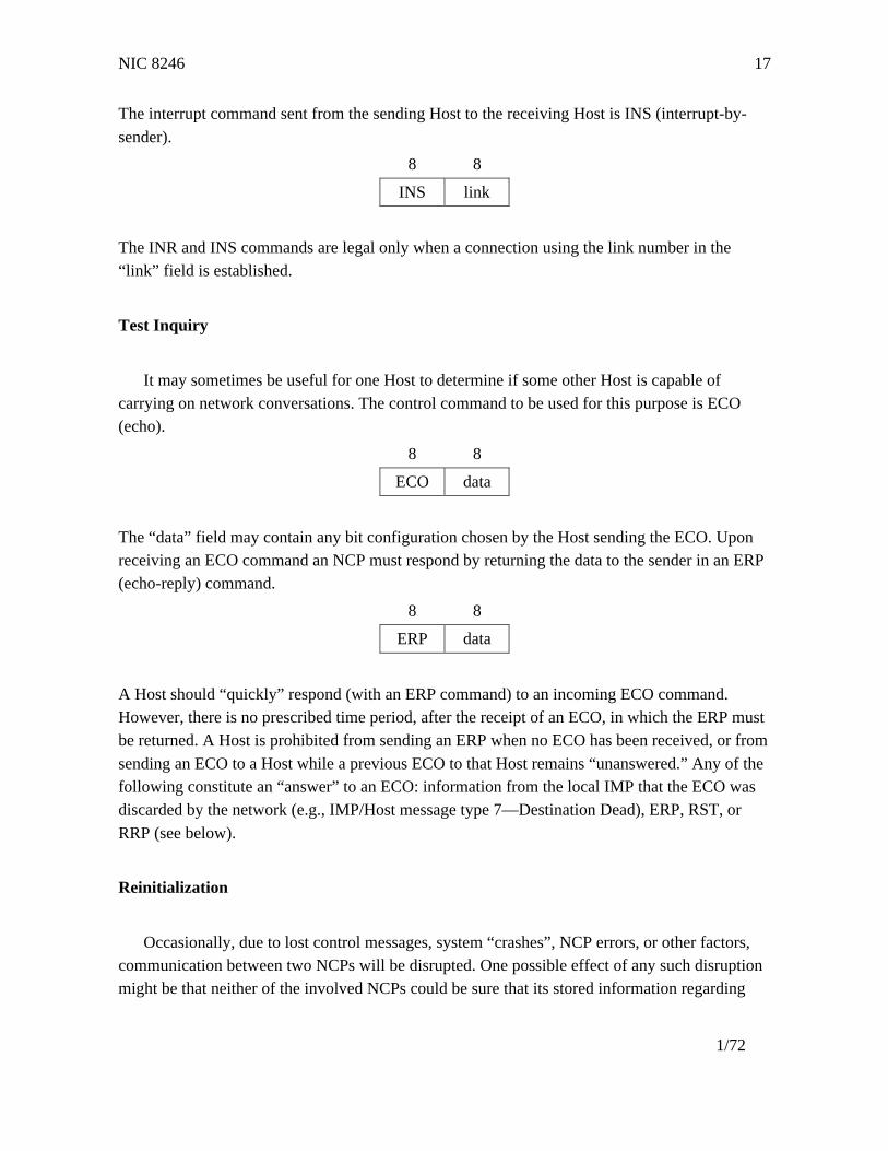
Interrupts
The second level protocol has included a mechanism by which the transmission over a
connection may be “interrupted.” The meaning of the “interrupt” is not defined at this level, butis made available for use by outer layers of protocol. The interrupt command sent from thereceiving Host to the sending Host is INR (interrupt-by-receiver).
8 8
INR link
* In particular, fractional returns must be rounded up, not truncated.
NIC 8246 17
1/72
The interrupt command sent from the sending Host to the receiving Host is INS (interrupt-by-
sender).
8 8
INS link
The INR and INS commands are legal only when a connection using the link number in the“link” field is established.
Test Inquiry
It may sometimes be useful for one Host to determine if some other Host is capable ofcarrying on network conversations. The control command to be used for this purpose is ECO(echo).
8 8
ECO data
The “data” field may contain any bit configuration chosen by the Host sending the ECO. Uponreceiving an ECO command an NCP must respond by returning the data to the sender in an ERP(echo-reply) command.
8 8
ERP data
A Host should “quickly” respond (with an ERP command) to an incoming ECO command.However, there is no prescribed time period, after the receipt of an ECO, in which the ERP mustbe returned. A Host is prohibited from sending an ERP when no ECO has been received, or from
sending an ECO to a Host while a previous ECO to that Host remains “unanswered.” Any of thefollowing constitute an “answer” to an ECO: information from the local IMP that the ECO wasdiscarded by the network (e.g., IMP/Host message type 7—Destination Dead), ERP, RST, or
RRP (see below).
Reinitialization
Occasionally, due to lost control messages, system “crashes”, NCP errors, or other factors,communication between two NCPs will be disrupted. One possible effect of any such disruptionmight be that neither of the involved NCPs could be sure that its stored information regarding
NIC 8246 18
1/72
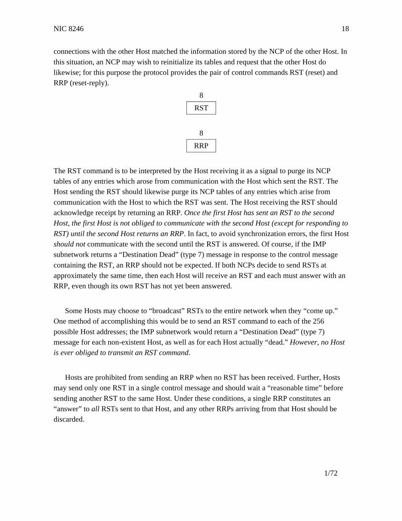
connections with the other Host matched the information stored by the NCP of the other Host. In
this situation, an NCP may wish to reinitialize its tables and request that the other Host dolikewise; for this purpose the protocol provides the pair of control commands RST (reset) andRRP (reset-reply).
8
RST
8
RRP
The RST command is to be interpreted by the Host receiving it as a signal to purge its NCPtables of any entries which arose from communication with the Host which sent the RST. TheHost sending the RST should likewise purge its NCP tables of any entries which arise from
communication with the Host to which the RST was sent. The Host receiving the RST shouldacknowledge receipt by returning an RRP. Once the first Host has sent an RST to the second
Host, the first Host is not obliged to communicate with the second Host (except for responding to
RST) until the second Host returns an RRP. In fact, to avoid synchronization errors, the first Hostshould not communicate with the second until the RST is answered. Of course, if the IMPsubnetwork returns a “Destination Dead” (type 7) message in response to the control message
containing the RST, an RRP should not be expected. If both NCPs decide to send RSTs atapproximately the same time, then each Host will receive an RST and each must answer with anRRP, even though its own RST has not yet been answered.
Some Hosts may choose to “broadcast” RSTs to the entire network when they “come up.”One method of accomplishing this would be to send an RST command to each of the 256
possible Host addresses; the IMP subnetwork would return a “Destination Dead” (type 7)message for each non-existent Host, as well as for each Host actually “dead.” However, no Host
is ever obliged to transmit an RST command.
Hosts are prohibited from sending an RRP when no RST has been received. Further, Hostsmay send only one RST in a single control message and should wait a “reasonable time” before
sending another RST to the same Host. Under these conditions, a single RRP constitutes an“answer” to all RSTs sent to that Host, and any other RRPs arriving from that Host should bediscarded.
NIC 8246 19
1/72
IV. DECLARATIVE SPECIFICATIONS
Message Format
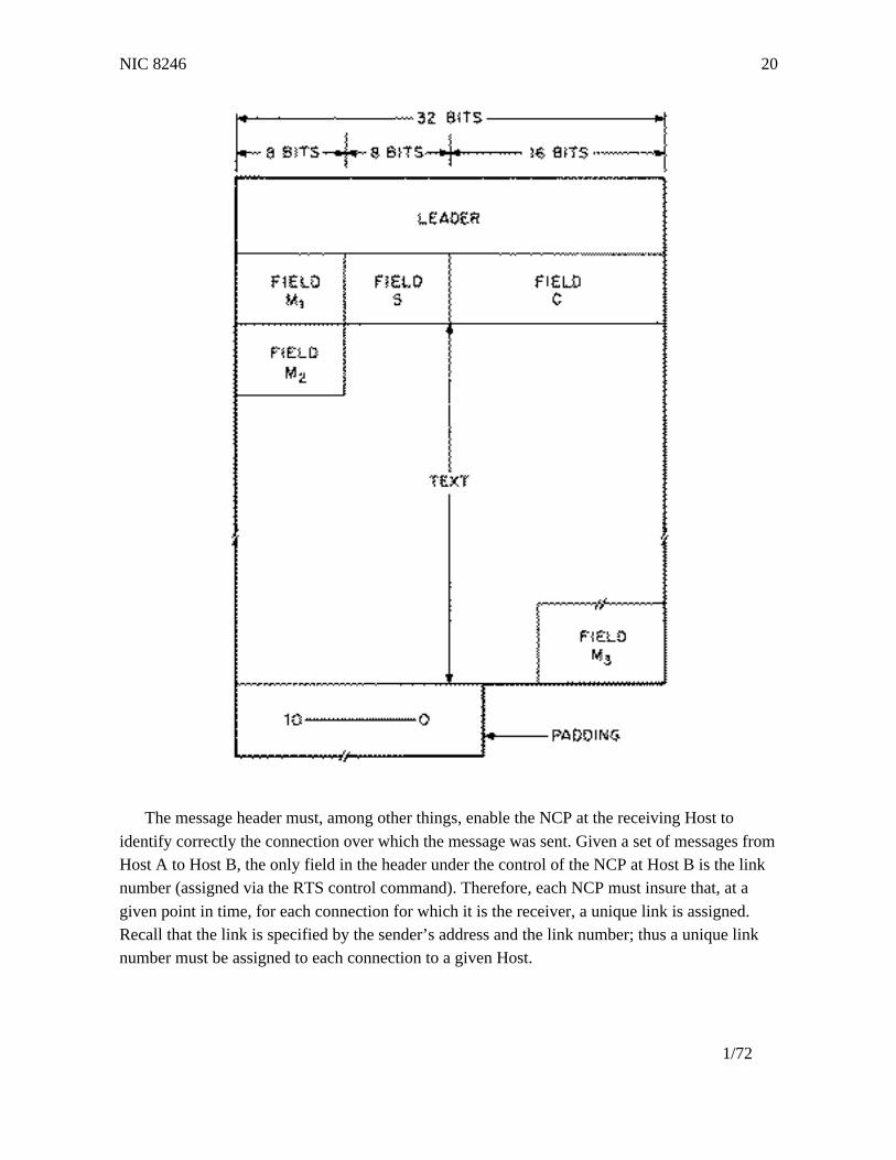
All Host-to-Host messages (i.e., messages of type zero) shall have a header 72 bits longconsisting of the following fields (see Figure 1):
Bits 1–32 Leader—The contents of this field must be constructed according to thespecifications contained in BBN Report Number 1822.
Bits 33–40 Field M1—Must be zero.
Bits 41–48 Field S—Connection byte size. This size must be identical to the byte size in
the STR used in establishing the connection. If this message is beingtransmitted over the control link the connection byte size must be 8.
Bits 49–64 Field C—Byte Count. This field specifies the number of bytes in the textportion of the message. A zero value in the C field is explicitly permitted.
Bits 65–72 Field M2—Must be zero.
Following the header, the message shall consist of a text field of C bytes, where each byte is S
bits in length. Following the text there will be field M3 followed by padding. The M3 field is zeroor more bits long and must be all zero; this field may be used to fill out a message to a wordboundary.
NIC 8246 20
1/72
The message header must, among other things, enable the NCP at the receiving Host to
identify correctly the connection over which the message was sent. Given a set of messages fromHost A to Host B, the only field in the header under the control of the NCP at Host B is the linknumber (assigned via the RTS control command). Therefore, each NCP must insure that, at a
given point in time, for each connection for which it is the receiver, a unique link is assigned.Recall that the link is specified by the sender’s address and the link number; thus a unique linknumber must be assigned to each connection to a given Host.
NIC 8246 21
1/72
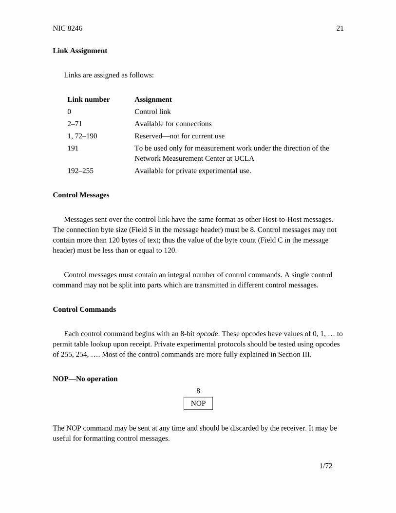
Link Assignment
Links are assigned as follows:
Link number Assignment
0 Control link
2–71 Available for connections
1, 72–190 Reserved—not for current use
191 To be used only for measurement work under the direction of theNetwork Measurement Center at UCLA
192–255 Available for private experimental use.
Control Messages
Messages sent over the control link have the same format as other Host-to-Host messages.The connection byte size (Field S in the message header) must be 8. Control messages may not
contain more than 120 bytes of text; thus the value of the byte count (Field C in the messageheader) must be less than or equal to 120.
Control messages must contain an integral number of control commands. A single controlcommand may not be split into parts which are transmitted in different control messages.
Control Commands
Each control command begins with an 8-bit opcode. These opcodes have values of 0, 1, … to
permit table lookup upon receipt. Private experimental protocols should be tested using opcodesof 255, 254, …. Most of the control commands are more fully explained in Section III.
NOP—No operation
8
NOP
The NOP command may be sent at any time and should be discarded by the receiver. It may beuseful for formatting control messages.
NIC 8246 22
1/72
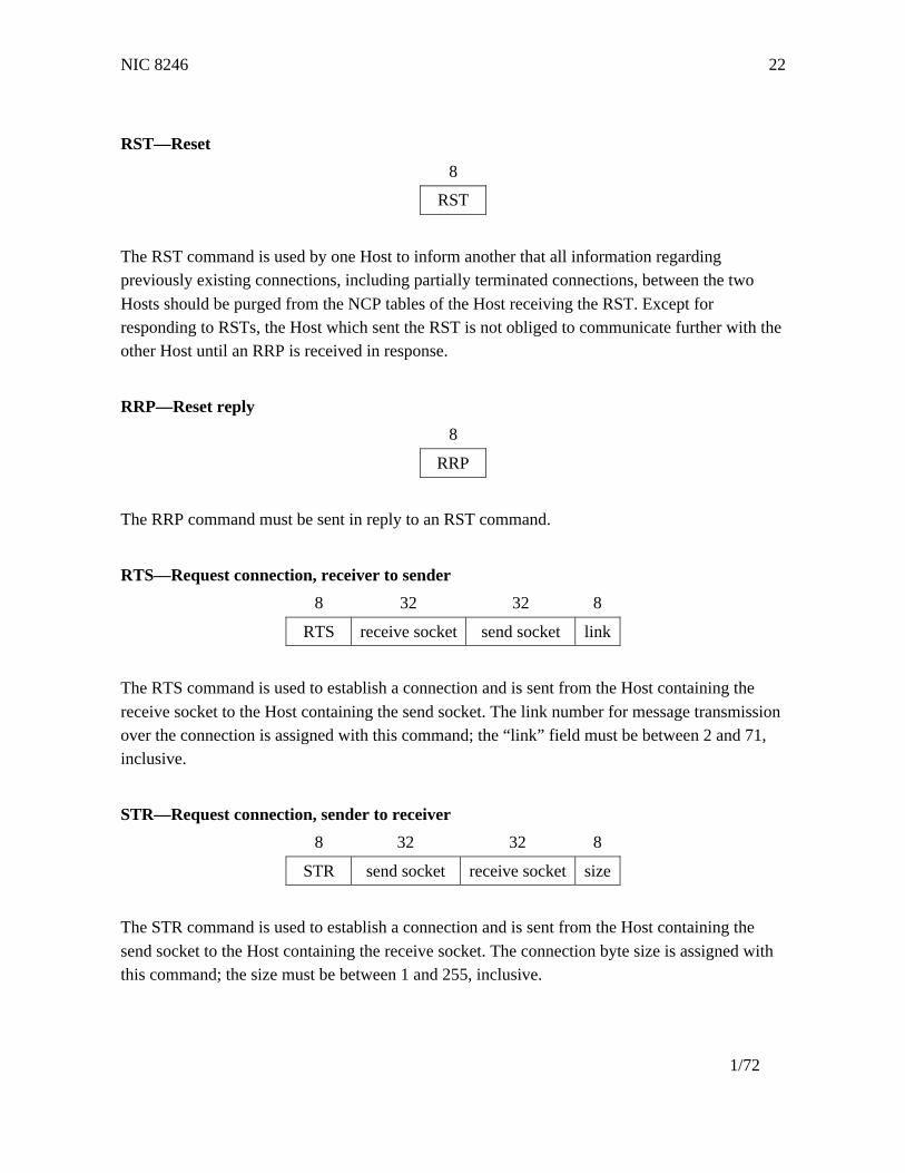
RST—Reset
8
RST
The RST command is used by one Host to inform another that all information regardingpreviously existing connections, including partially terminated connections, between the two
Hosts should be purged from the NCP tables of the Host receiving the RST. Except forresponding to RSTs, the Host which sent the RST is not obliged to communicate further with theother Host until an RRP is received in response.
RRP—Reset reply
8
RRP
The RRP command must be sent in reply to an RST command.
RTS—Request connection, receiver to sender
8 32 32 8
RTS receive socket send socket link
The RTS command is used to establish a connection and is sent from the Host containing the
receive socket to the Host containing the send socket. The link number for message transmissionover the connection is assigned with this command; the “link” field must be between 2 and 71,inclusive.
STR—Request connection, sender to receiver
8 32 32 8
STR send socket receive socket size
The STR command is used to establish a connection and is sent from the Host containing the
send socket to the Host containing the receive socket. The connection byte size is assigned withthis command; the size must be between 1 and 255, inclusive.
NIC 8246 23
1/72
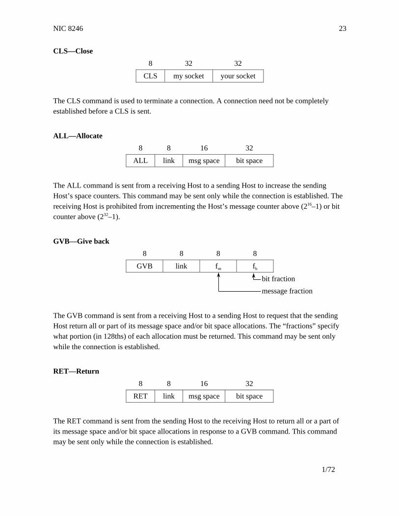
CLS—Close
8 32 32
CLS my socket your socket
The CLS command is used to terminate a connection. A connection need not be completelyestablished before a CLS is sent.
ALL—Allocate
8 8 16 32
ALL link msg space bit space
The ALL command is sent from a receiving Host to a sending Host to increase the sendingHost’s space counters. This command may be sent only while the connection is established. The
receiving Host is prohibited from incrementing the Host’s message counter above (216–1) or bitcounter above (232–1).
GVB—Give back
8 8 8 8
GVB link fm fb
bit fraction
message fraction
The GVB command is sent from a receiving Host to a sending Host to request that the sendingHost return all or part of its message space and/or bit space allocations. The “fractions” specifywhat portion (in 128ths) of each allocation must be returned. This command may be sent only
while the connection is established.
RET—Return
8 8 16 32
RET link msg space bit space
The RET command is sent from the sending Host to the receiving Host to return all or a part ofits message space and/or bit space allocations in response to a GVB command. This commandmay be sent only while the connection is established.
NIC 8246 24
1/72
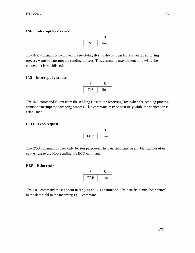
INR—Interrupt by receiver
8 8
INR link
The INR command is sent from the receiving Host to the sending Host when the receivingprocess wants to interrupt the sending process. This command may be sent only while the
connection is established.
INS—Interrupt by sender
8 8
INS link
The INS command is sent from the sending Host to the receiving Host when the sending processwants to interrupt the receiving process. This command may be sent only while the connection isestablished.
ECO—Echo request
8 8
ECO data
The ECO command is used only for test purposes. The data field may be any bit configuration
convenient to the Host sending the ECO command.
ERP—Echo reply
8 8
ERP data
The ERP command must be sent in reply to an ECO command. The data field must be identicalto the data field in the incoming ECO command.
NIC 8246 25
1/72
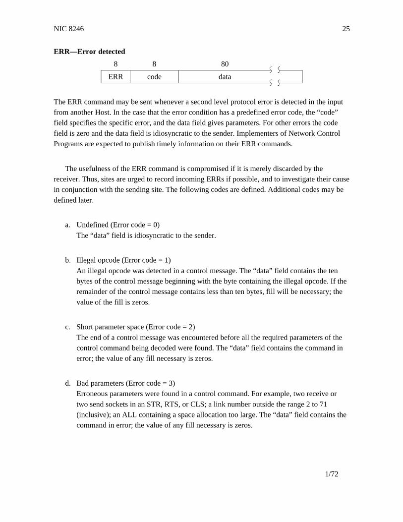
ERR—Error detected
8 8 80
ERR code data
The ERR command may be sent whenever a second level protocol error is detected in the inputfrom another Host. In the case that the error condition has a predefined error code, the “code”field specifies the specific error, and the data field gives parameters. For other errors the code
field is zero and the data field is idiosyncratic to the sender. Implementers of Network ControlPrograms are expected to publish timely information on their ERR commands.
The usefulness of the ERR command is compromised if it is merely discarded by thereceiver. Thus, sites are urged to record incoming ERRs if possible, and to investigate their causein conjunction with the sending site. The following codes are defined. Additional codes may be
defined later.
a. Undefined (Error code = 0)
The “data” field is idiosyncratic to the sender.
b. Illegal opcode (Error code = 1)
An illegal opcode was detected in a control message. The “data” field contains the tenbytes of the control message beginning with the byte containing the illegal opcode. If theremainder of the control message contains less than ten bytes, fill will be necessary; the
value of the fill is zeros.
c. Short parameter space (Error code = 2)
The end of a control message was encountered before all the required parameters of thecontrol command being decoded were found. The “data” field contains the command inerror; the value of any fill necessary is zeros.
d. Bad parameters (Error code = 3)Erroneous parameters were found in a control command. For example, two receive or
two send sockets in an STR, RTS, or CLS; a link number outside the range 2 to 71(inclusive); an ALL containing a space allocation too large. The “data” field contains thecommand in error; the value of any fill necessary is zeros.
NIC 8246 26
1/72
e. Request on a non-existent socket (Error code = 4)
A request other than STR or RTS was made for a socket (or link) for which no RFC hasbeen transmitted in either direction. This code is meant to indicate to the NCP receiving itthat functions are being performed out of order. The “data” field contains the command
in error; the value of any fill necessary is zeros.
f. Socket (link) not connected (Error code = 5)
There are two cases:
1. A control command other than STR or RTS refers to a socket (or link) which is not
part of an established connection. This code would be used when one RFC had beentransmitted, but the matching RFC had not. It is meant to indicate the failure of theNCP receiving it to wait for a response to an RFC. The “data” field contains the
command in error; the value of any fill necessary is zeros.
2. A message was received over a link which is not currently being used for any
connection. The contents of the “data” field are the message header followed by thefirst eight bits of text (if any) or zeros.
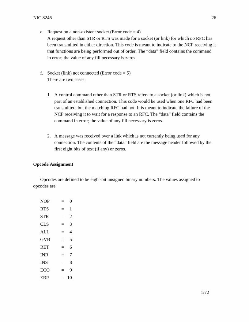
Opcode Assignment
Opcodes are defined to be eight-bit unsigned binary numbers. The values assigned to
opcodes are:
NOP = 0
RTS = 1
STR = 2
CLS = 3
ALL = 4
GVB = 5
RET = 6
INR = 7
INS = 8
ECO = 9
ERP = 10
NIC 8246 27
1/72
ERR = 11
RST = 12
RRP = 13
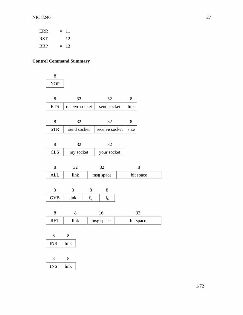
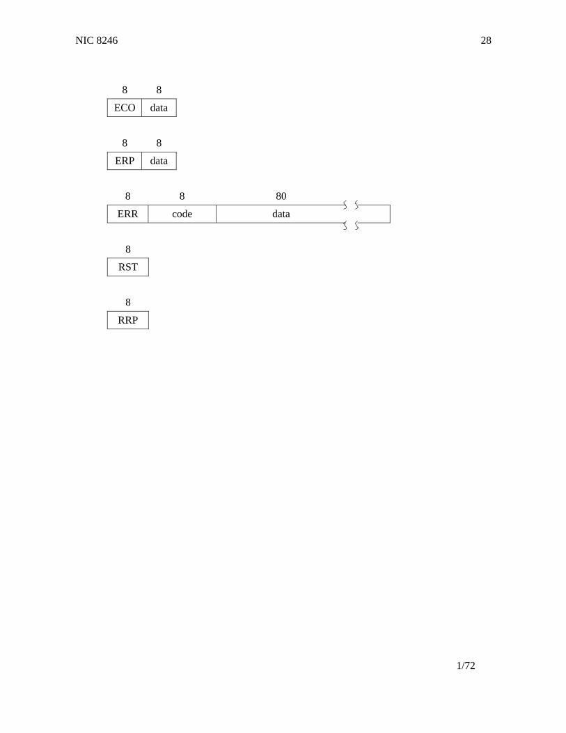
Control Command Summary
8
NOP
8 32 32 8
RTS receive socket send socket link
8 32 32 8
STR send socket receive socket size
8 32 32
CLS my socket your socket
8 32 32 8
ALL link msg space bit space
8 8 8 8
GVB link fm fb
8 8 16 32
RET link msg space bit space
8 8
INR link
8 8
INS link
NIC 8246 28
1/72
8 8
ECO data
8 8
ERP data
8 8 80
ERR code data
8
RST
8
RRP
![[MS-DHCPM-Diff]: Microsoft Dynamic Host Configuration Protocol (DHCP) Server …... · 2017. 5. 25. · Microsoft Dynamic Host Configuration Protocol (DHCP) Server Management Protocol](https://img.dokumen.tips/doc/110x75/614788e9afbe1968d37a1cf4/ms-dhcpm-diff-microsoft-dynamic-host-configuration-protocol-dhcp-server-.jpg)

![Dynamic Host Configuration Protocol DHCP [RFC 2131 - 1997 ] · 2016-12-04 · Dynamic Host Configuration Protocol DHCP [RFC 2131 - 1997 ] 2 ... Source Destination Protocol Info 0.0.0.0](https://img.dokumen.tips/doc/110x75/5f4bcafcc73ffb6385247ba9/dynamic-host-configuration-protocol-dhcp-rfc-2131-1997-2016-12-04-dynamic.jpg)

![[MS-HGSA]: Host Guardian Service: Attestation Protocol · [MS-HGSA] - v20190530 Host Guardian Service: Attestation Protocol ... Host Guardian Service: Attestation Protocol ... No](https://img.dokumen.tips/doc/110x75/5ed9ec07797e8f5f5a315be2/ms-hgsa-host-guardian-service-attestation-protocol-ms-hgsa-v20190530-host.jpg)