Embed Size (px)
Citation preview

HospitalProduct ApplicationGuide


1
Table of Contents
Introduction . . . . . . . . . . . . . . . . . . . . . . . . . . . . . . . . . . . . . . . . .3
Glossary . . . . . . . . . . . . . . . . . . . . . . . . . . . . . . . . . . . . . . . . . . .5
Hospital Power Systems . . . . . . . . . . . . . . . . . . . . . . . . . . . . . . . .8Radial – Generator . . . . . . . . . . . . . . . . . . . . . . . . . . . . . . . . . . . . . . . . . . .10Dual Source and Radial Secondary – Generators . . . . . . . . . . . . . . . . . . . .10Secondary Selective – Generators . . . . . . . . . . . . . . . . . . . . . . . . . . . . . . .11Dual Source and Secondary Selective – Generators . . . . . . . . . . . . . . . . . .11
Selective Coordination . . . . . . . . . . . . . . . . . . . . . . . . . . . . . . . . .12Circuit breakers vs. fuses . . . . . . . . . . . . . . . . . . . . . . . . . . . . . . . . . . . . . .12
Ground Fault Protection . . . . . . . . . . . . . . . . . . . . . . . . . . . . . . . .14
Typical Hospital Product One Line Diagram . . . . . . . . . . . . . . . . . .16
Medium Voltage Product Offering . . . . . . . . . . . . . . . . . . . . . . . . .18Metalclad™ Switchgear . . . . . . . . . . . . . . . . . . . . . . . . . . . . . . . . . . . . . . . . .18Arc Terminator . . . . . . . . . . . . . . . . . . . . . . . . . . . . . . . . . . . . . . . . . . . . . .19Metal Enclosed Switchgear . . . . . . . . . . . . . . . . . . . . . . . . . . . . . . . . . . . . .19Medium Voltage Motor Control Centers . . . . . . . . . . . . . . . . . . . . . . . . . . .20Medium Voltage Power Factor Correction Capacitors . . . . . . . . . . . . . . . . .21Medium Voltage Transformers . . . . . . . . . . . . . . . . . . . . . . . . . . . . . . . . . .21Packaged Unit Substation . . . . . . . . . . . . . . . . . . . . . . . . . . . . . . . . . . . . . .22
Power Monitoring and NetworkCommunications Products . . . . . . . . . . . . . . . . . . . . . . . . . . . . . .23
Protective Relays . . . . . . . . . . . . . . . . . . . . . . . . . . . . . . . . . . . . . . . . . . . .24Power Monitoring . . . . . . . . . . . . . . . . . . . . . . . . . . . . . . . . . . . . . . . . . . . .24Circuit Monitors . . . . . . . . . . . . . . . . . . . . . . . . . . . . . . . . . . . . . . . . . . . . .25Power Meters . . . . . . . . . . . . . . . . . . . . . . . . . . . . . . . . . . . . . . . . . . . . . . .25PowerLogic® Generator Testing Documentation . . . . . . . . . . . . . . . . . . . . .26
Low Voltage Product Offering . . . . . . . . . . . . . . . . . . . . . . . . . . . .27Low Voltage Switchgear . . . . . . . . . . . . . . . . . . . . . . . . . . . . . . . . . . . . . . .27Switchboards – Rear Connected QED-6 with Masterpact®
Circuit Breakers and PowerLogic Monitoring . . . . . . . . . . . . . . . . . . . . . . .28Switchboards . . . . . . . . . . . . . . . . . . . . . . . . . . . . . . . . . . . . . . . . . . . . . . .29Panelboards . . . . . . . . . . . . . . . . . . . . . . . . . . . . . . . . . . . . . . . . . . . . . . . .30Square D® Integrated Power and Control Solutions . . . . . . . . . . . . . . . . . . .33Lighting Control – PowerLink® G3 . . . . . . . . . . . . . . . . . . . . . . . . . . . . . . .34Low Voltage Motor Control Centers (MCC) . . . . . . . . . . . . . . . . . . . . . . . . .34Harmonic Filtering and Power Factor Correction . . . . . . . . . . . . . . . . . . . .36Low Voltage Energy Efficient Transformers . . . . . . . . . . . . . . . . . . . . . . . .37
2
Medical Products . . . . . . . . . . . . . . . . . . . . . . . . . . . . . . . . . . . .37Dual Output Voltage Isolation Panels . . . . . . . . . . . . . . . . . . . . . . . . . . . . .38Duplex Hospital Isolation Panel . . . . . . . . . . . . . . . . . . . . . . . . . . . . . . . . .39Medical Headwall . . . . . . . . . . . . . . . . . . . . . . . . . . . . . . . . . . . . . . . . . . . .40
Medium and Low Voltage Circuit Breakers . . . . . . . . . . . . . . . . . . .42Masterpact® Circuit Breakers . . . . . . . . . . . . . . . . . . . . . . . . . . . . . . . . . . .42Medium Voltage Vacuum Circuit Breakers . . . . . . . . . . . . . . . . . . . . . . . . .44PowerPact® H- and J- Frame Molded Case Circuit Breakers . . . . . . . . . . . .44
Enclosed Drives . . . . . . . . . . . . . . . . . . . . . . . . . . . . . . . . . . . . .45
Other Power Distribution products . . . . . . . . . . . . . . . . . . . . . . . . .45
Square D Services . . . . . . . . . . . . . . . . . . . . . . . . . . . . . . . . . . . .46Products and Engineering Services . . . . . . . . . . . . . . . . . . . . . . . . . . . . . .46Engineering Studies . . . . . . . . . . . . . . . . . . . . . . . . . . . . . . . . . . . . . . . . . .46New Installation Services . . . . . . . . . . . . . . . . . . . . . . . . . . . . . . . . . . . . . .47Retrofill and Upgrade . . . . . . . . . . . . . . . . . . . . . . . . . . . . . . . . . . . . . . . . .47Maintenance and Testing Preventive Maintenance . . . . . . . . . . . . . . . . . . .48Workplace Safety . . . . . . . . . . . . . . . . . . . . . . . . . . . . . . . . . . . . . . . . . . . .48
3
IntroductionSchneider Electric offers a robust line-up of products and services that are
ideally suited to the needs of the healthcare industry. The electrical distribution
and control equipment used in healthcare facilities must offer the highest
possible levels of reliability, safety and yet be flexible enough to cope with the
rapidly changing needs of a healthcare customer.
Providing innovative, cost effective solutions that reduce costs throughout the
lifecycle of the facility is critical. Through its close association with those
involved in the specification, design, construction and operation of buildings,
Schneider Electric has developed and understanding of the key requirements
of the healthcare customer. Continuous development, carefully focused on
satisfying customers’ requirements, means that today, Schneider Electric’s
portfolio of products and services for the healthcare segment is more
comprehensive than ever before.

4

5
GlossaryFollowing is a list of terms and definitions that are used in hospitals. Many of the definitions are definedper the NFPA 99 and the National Electrical Code® (NEC®).
Alternate Power Source — One or more generator sets, or battery systems where permitted, intended toprovide power during the interruption of the normal electrical services or the public utility electricalservice intended to provide power during interruption of service normally provided by the generatingfacilities on the premises. The alternate source of power shall be one of the following:
� Generator(s) driven by some form of prime mover(s) and located on the premises
� Another generating unit(s) where the normal source consists of a generating unit(s) located on the premises
� An external utility service when the normal source consists of a generating unit(s) located on the premises
Arc Flash — According to NFPA 70E, arc flash is a “dangerous condition associated with the release ofenergy caused by an electrical arc.” It is measured in terms of arc flash incident energy (cal/cm2), which isused to determine the level of personnel protection equipment (PPE), and in terms of an arc flashprotection boundary. An arc flash study is performed to determine the proper PPE equipment workers arerequired to wear and the flash protection boundary when working on or around exposed energized parts.
Arc Resistance Switchgear — Equipment designed to withstand the effects of an internal arcing faultwith the doors closed. Equipment is considered arc resistant by successfully meeting the testrequirements of ANSI C37.20.7.
ATS — Sometimes has several definitions, automatic transfer switch, automatic transfer system or auto-throw-over system between two paralleled sources.
Critical Branch — A subsystem of the emergency system consisting of feeders and branch circuitssupplying energy to task illumination, special power circuits, and selected receptacles serving areas andfunctions related to patient care, and which are connected to alternate power sources by one or moretransfer switches during interruption of the normal power source. The critical branch of the emergencysystem shall supply power for task illumination, fixed equipment, selected receptacles, and special powercircuits serving the following areas and functions related to patient care.
� Critical care areas that utilize anesthetizing gases — task illumination, selected receptacles and fixed equipment
� The isolated power systems in special environments
� Patient care areas — task illumination and selected receptacles in the following:� Infant nurseries� Medication preparation areas� Pharmacy dispensing areas� Selected acute nursing areas� Psychiatric bed areas (omit receptacles)� Ward treatment rooms� Nurses’ stations (unless adequately lighted by corridor luminaries)� Additional specialized patient care task illumination and receptacles, where needed� Nurse call systems� Blood, bone and tissue banks� Telephone equipment rooms and closets
� Task illumination, selected receptacles and selected power circuits for the following:� General care beds (at least one duplex receptacle per patient bedroom) � Angiographic labs� Cardiac catheterization labs� Coronary care units� Hemodialysis rooms or areas� Selected emergency room treatment areas

6
� Human physiology labs� Intensive care units� Postoperative recovery rooms
Critical Care Areas — Critical care areas are those special care units, intensive care units, coronary careunits, angiography laboratories, cardiac catheterization laboratories, delivery rooms, operating rooms,and similar areas in which patients are intended to be subjected to invasive procedures and connected toline-operated, electromedical devices.
Electrical Life-Support Equipment — Electrically powered equipment whose continuous operation isnecessary to maintain a patient’s life.
Equipment for Delayed Automatic Connection — This equipment shall be arranged for delayed automaticconnection to alternate power source. This means an outage to this equipment can exceed 10 seconds.
� Central suction systems serving medical and surgical functions, including controls. Such suctionsystems shall be permitted on the critical branch
� Sump pumps and other equipment required to operate for the safety of major apparatus, includingassociated control systems and alarms
� Compressed air systems serving medical and surgical functions, including controls. Such air systemsshall be permitted on the critical branch
� Smoke control and stair pressurization systems, or both
� Kitchen hood supply or exhaust systems, or both, if required to operate during a fire in or under the hood
� Exception: Sequential delayed automatic connection to the alternate power source to preventoverloading the generator shall be permitted where engineering studies indicate it is necessary
Equipment for Delayed Automatic or Manual Connection — This equipment shall be arranged for eitherdelayed automatic or manual connection to alternate power source. As mentioned for delayed automaticconnection, an outage to this equipment can exceed 10 seconds.
� Heating equipment to provide heating for operating, delivery, labor, recovery, intensive care, coronarycare, nurseries, infection/isolation rooms, emergency treatment spaces and general patient rooms
� An elevator(s) selected to provide service to patient, surgical, obstetrical and ground floors duringinterruption of normal power
� Supply, return and exhaust ventilating systems for surgical and obstetrical delivery suites, intensivecare, coronary care, nurseries, infection/isolation rooms, emergency treatment spaces and exhaustfans for laboratory fume hoods, nuclear medicine areas where radioactive material is used, ethyleneoxide evacuation and anesthesia evacuation
� Hyperbaric facilities
� Hypobaric facilities
� Automatically operated doors
� Minimal electrically heated autoclaving equipment shall be permitted to be arranged for eitherautomatic or manual connection to the alternate source
� Selected controls
Emergency System — A system of feeders and branch circuits meeting the requirements of the NEC andintended to supply alternate power to a limited number of prescribed functions vital to the protection of lifeand patient safety, with automatic restoration of electrical power within 10 seconds of power interruption.
Essential Electrical System (ESS) — A system comprised of alternate sources of power and allconnected distribution systems and ancillary equipment, designed to ensure continuity of electrical powerto designated areas and functions of a health care facility during disruption of normal power sources andalso designed to minimize disruption within the internal wiring system.
Fault Hazard Current — The hazard current of a given isolated system with all devices connected except the line isolation monitor.

7
General Care Areas — General care areas are patient bedrooms, examining rooms, treatment rooms,clinics and similar areas in which it is intended that the patient shall come in contact with ordinaryappliances such as a nurse call system, electrical beds, examining lamps, telephone and entertainmentdevices. In such areas, it may also be intended that patients be connected to electromedical devices (suchas heating pads, electrocardiographs, drainage pumps, monitors, otoscopes, ophthalmoscopes,intravenous lines, etc.).
Hazard Current — For a given set of connections in an isolated power system, the total current thatwould flow through a low impedance if it were connected between either isolated conductor and ground.
Health Care Facilities — are defined by National Fire Protection Agency (NFPA), “Buildings or portions ofbuildings that contain, but are not limited to, occupancies such as hospitals; nursing homes; limited care;supervisory care; clinics; medical and dental offices and ambulatory care, whether permanent or movable”.
Hospital — A building or part thereof used for the medical, psychiatric, obstetrical, or surgical care, on a24-hour basis, of four or more inpatients. Hospital shall include general hospitals, mental hospitals,tuberculosis hospitals, children’s hospitals and any such facilities providing inpatient care.
Isolated Power System — A system comprising an isolating transformer or its equivalent, a line isolationmonitor and its ungrounded circuit conductors.
Isolation Transformer — A transformer of the multiple-winding type, with the primary and secondarywindings physically separated, which inductively couples its secondary winding to the grounded feedersystems that energize its primary winding.
Life Safety Branch Systems — A subsystem of the emergency system consisting of feeders, branchcircuits and intended to provide adequate power needs to ensure safety to patients and personnel and whichare automatically connected to alternate power sources during interruption of the normal power source. Nofunction other than those listed in (a) through (f) shall be connected to the life safety branch. The life safetybranch of the emergency system shall supply power for the following lighting, receptacles and equipment.
� Illumination of means of egress, such as lighting required for corridors, passageways, stairways andlandings at exit doors and all necessary ways of approach to exits. Switching arrangements to transferpatient corridor lighting in hospitals from general illumination circuits to night illumination circuitsshall be permitted provided only one of two circuits can be selected and both circuits cannot beextinguished at the same time.
� Exit signs and exit directional signs
� Alarm and alerting systems. Alarm and alerting systems including the following:� Fire alarms� Alarms required for systems used for the piping of nonflammable medical gases
� Hospital communications systems, where used for issuing instructions during emergency conditions
� Generator set location; task illumination battery charger for emergency battery-powered lightingunit(s) and selected receptacles at the generator set location
� Elevator cab lighting and control
Line Isolation Monitor — A test instrument designed to continually check the balanced and unbalancedimpedance from each line of an isolated circuit to ground and equipped with a built-in test circuit toexercise the alarm without adding to the leakage current hazard.
Monitor Hazard Current — The hazard current of the line isolation monitor alone.
Paralleling Switchgear — Two or more power sources are connected to a load in a parallel. Each sourcemust have equal voltage and frequency values, and must share in the load for both real power (kW) andreactive power (kVAR). Operating one of more generators in parallel with the utility typically requireselectrically operated circuit breakers for the generators and utility services, fast update rate voltage andfrequency transducers, PLCs, and protective relays to manage the interconnection between localgenerators and the utility distribution grid. Auto-throw-over scheme control backup generators andelectrically operated breakers in switchgear (via PLC control) during utility outages or testing.

8
Patient Equipment Grounding Point — A jack or terminal bus that serves as the collection point forredundant grounding of electric appliances serving a patient vicinity or for grounding other items in orderto eliminate electromagnetic interference problems.
Reference Grounding Point — The ground bus of the panelboard or isolated power system panelsupplying the patient care area.
Rotary UPS — A rotary UPS system uses a motor-generator set, with its rotating inertia, to ride throughbrief power interruptions. Power goes to critical loads by means of a generator driven by an AC or DCmotor. The motor-generator set will ride-thru power interruptions long enough to allow generators tobackup essential electrical systems.
Selective Coordination — Localization of an overcurrent condition to restrict outages to the circuit orequipment affected, accomplished by the choice of overcurrent protective devices and their ratings orsettings. The following National Electrical Code® (NEC®) sections address selective coordination:
� 517.26 Application of other articles. The essential electrical system shall meet the requirements ofArticle 700, except as amended by Article 517
� 700.27 Coordination. Emergency system(s) overcurrent devices shall be selectively coordinated withall supply side overcurrent protective devices
� 701.18 Coordination. Legally required standby system(s) overcurrent devices shall be selectivelycoordinated with all supply side overcurrent protective devices
Total Hazard Current — The hazard current of a given isolated system with all devices, including the lineisolation monitor, connected.
UPS — An uninterruptible power supply is a battery backup system that converts AC - DC (DC connectedto batteries) converts DC - AC and is continuously on-line. During a utility outage, the batteries willprovide power to critical loads for 10 to 45 minutes (depends on system design). During this time, theback up generators can start and backup essential electrical systems.
Hospital Power Systems There are several agencies and organizations that develop requirements for health care electricaldistribution system design. The following is a listing of some of the specific NFPA standards that affecthealth care facility design and implementation:
� NFPA 37 — Standard for Stationary Combustion Engines and Gas Turbines
� NFPA 70 — National Electrical Code
� NFPA 99 — Health Care Facilities
� NFPA 101 — Life Safety Code
� NFPA 110 — Standard for Emergency and Standby Power Systems
� NFPA 111 — Standard on Stored Electrical Energy Emergency and Standby Power Systems
These NFPA guidelines represent the most industry recognized standard requirements for health careelectrical design. However, the electrical design engineer should consult with the authorities havingjurisdiction over the local region for specific electrical distribution requirements.
All electrical power systems in health care facilities are very important, though some loads are not criticalto the safe operation of the facility. These non-essential or normal loads include things such as generallighting, general lab equipment, non-critical service equipment, patient care areas, etc. These loads arenot required to be backed up with an alternate source of power. However, the electrical systemrequirements for the Essential Electrical System (EES) do require an alternate source of power. Accordingthe 2005 NFPA 99, Section 4.4, if electrical life support or critical care areas are present then facility isclassified as ESS Type 1. ESS Type 1 has the most stringent requirements for providing continuity ofelectrical service.
9
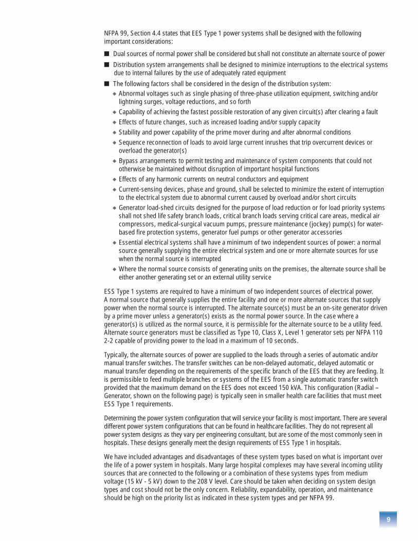
NFPA 99, Section 4.4 states that EES Type 1 power systems shall be designed with the following important considerations:
� Dual sources of normal power shall be considered but shall not constitute an alternate source of power
� Distribution system arrangements shall be designed to minimize interruptions to the electrical systemsdue to internal failures by the use of adequately rated equipment
� The following factors shall be considered in the design of the distribution system: � Abnormal voltages such as single phasing of three-phase utilization equipment, switching and/or
lightning surges, voltage reductions, and so forth� Capability of achieving the fastest possible restoration of any given circuit(s) after clearing a fault� Effects of future changes, such as increased loading and/or supply capacity� Stability and power capability of the prime mover during and after abnormal conditions� Sequence reconnection of loads to avoid large current inrushes that trip overcurrent devices or
overload the generator(s)� Bypass arrangements to permit testing and maintenance of system components that could not
otherwise be maintained without disruption of important hospital functions� Effects of any harmonic currents on neutral conductors and equipment� Current-sensing devices, phase and ground, shall be selected to minimize the extent of interruption
to the electrical system due to abnormal current caused by overload and/or short circuits� Generator load-shed circuits designed for the purpose of load reduction or for load priority systems
shall not shed life safety branch loads, critical branch loads serving critical care areas, medical aircompressors, medical-surgical vacuum pumps, pressure maintenance (jockey) pump(s) for water-based fire protection systems, generator fuel pumps or other generator accessories
� Essential electrical systems shall have a minimum of two independent sources of power: a normalsource generally supplying the entire electrical system and one or more alternate sources for usewhen the normal source is interrupted
� Where the normal source consists of generating units on the premises, the alternate source shall beeither another generating set or an external utility service
ESS Type 1 systems are required to have a minimum of two independent sources of electrical power. A normal source that generally supplies the entire facility and one or more alternate sources that supplypower when the normal source is interrupted. The alternate source(s) must be an on-site generator drivenby a prime mover unless a generator(s) exists as the normal power source. In the case where agenerator(s) is utilized as the normal source, it is permissible for the alternate source to be a utility feed.Alternate source generators must be classified as Type 10, Class X, Level 1 generator sets per NFPA 1102-2 capable of providing power to the load in a maximum of 10 seconds.
Typically, the alternate sources of power are supplied to the loads through a series of automatic and/ormanual transfer switches. The transfer switches can be non-delayed automatic, delayed automatic ormanual transfer depending on the requirements of the specific branch of the EES that they are feeding. Itis permissible to feed multiple branches or systems of the EES from a single automatic transfer switchprovided that the maximum demand on the EES does not exceed 150 kVA. This configuration (Radial –Generator, shown on the following page) is typically seen in smaller health care facilities that must meetESS Type 1 requirements.
Determining the power system configuration that will service your facility is most important. There are severaldifferent power system configurations that can be found in healthcare facilities. They do not represent allpower system designs as they vary per engineering consultant, but are some of the most commonly seen inhospitals. These designs generally meet the design requirements of ESS Type 1 in hospitals.
We have included advantages and disadvantages of these system types based on what is important overthe life of a power system in hospitals. Many large hospital complexes may have several incoming utilitysources that are connected to the following or a combination of these systems types from mediumvoltage (15 kV - 5 kV) down to the 208 V level. Care should be taken when deciding on system designtypes and cost should not be the only concern. Reliability, expandability, operation, and maintenanceshould be high on the priority list as indicated in these system types and per NFPA 99.
10
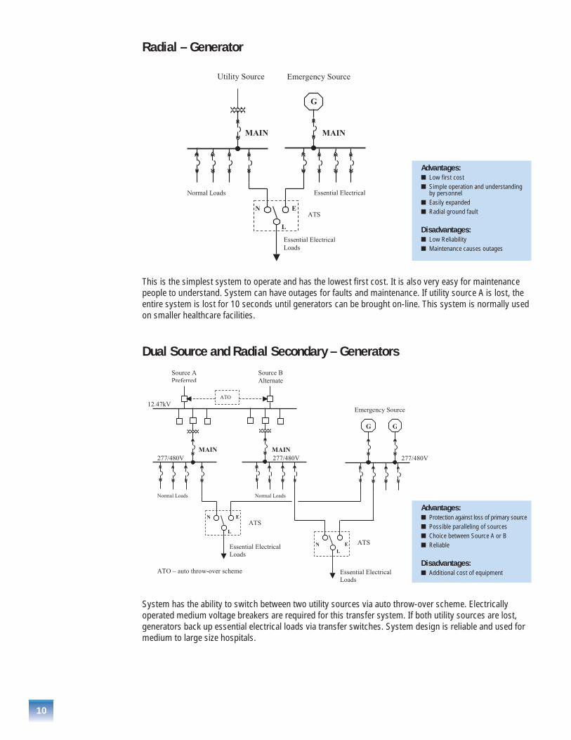
This is the simplest system to operate and has the lowest first cost. It is also very easy for maintenancepeople to understand. System can have outages for faults and maintenance. If utility source A is lost, theentire system is lost for 10 seconds until generators can be brought on-line. This system is normally usedon smaller healthcare facilities.
Dual Source and Radial Secondary – Generators
Radial – Generator
System has the ability to switch between two utility sources via auto throw-over scheme. Electricallyoperated medium voltage breakers are required for this transfer system. If both utility sources are lost,generators back up essential electrical loads via transfer switches. System design is reliable and used formedium to large size hospitals.
Advantages:� Low first cost� Simple operation and understanding
by personnel� Easily expanded� Radial ground fault
Disadvantages:� Low Reliability� Maintenance causes outages
Advantages:� Protection against loss of primary source� Possible paralleling of sources� Choice between Source A or B� Reliable
Disadvantages:� Additional cost of equipment

11
The secondary selective system allows the transfer of load from one transformer to the other with the useof electrically operated main and tie-breakers via auto throw-over scheme. This is important if onetransformer fails or needs maintenance. If both utility sources are lost, generators backup essentialelectrical loads via transfer switches. Transformer sizing is critical if all secondary loads are to be servicedfrom one transformer. This is usually accomplished by either loading the transformers to 50%, or byusing the transformer forced air (fan) rating with temperature controllers.
This system may require complex ground fault solution if both 480 Y/277 V transformers have separategrounds or if 3 pole transfer switches are used for 4 wire loads. This causes circulating current on theneutral busses. This system is common in large cities where the utility companies use transformers,located in vaults, to service hospitals.
Dual Source and Secondary Selective – Generators
Secondary Selective – Generators
This system combines the advantages of both primary sources and secondary selective systems usedwith backup generators. It not only provides the more reliable system, but also one of the most costlysystem. Evaluation of the probability of total downtime costs will be necessary to justify the additionalfirst cost. This system may require complex ground fault solution if both 480 Y/277 V transformers haveseparate ground points or if 3 pole transfer switches are used for 4 wire loads. This causes circulatingcurrent on the neutral busses. This power system is popular for large hospital complexes.
Advantages:� Normal operation as radial system
with stand-by generators� Isolation of cable or transformer for
faults or normal maintenance� Feed other side with use of
transfer scheme and electricallyoperated breakers
� Main and tie breakers can beinterchanged for maintenance to keepoutages to a minimum
Disadvantages:� Additional cost� Transformer load monitoring� May require complex ground fault
system if neutrals are tied together andsources have multiple grounding points
Advantages:� High Reliability� Combined advantages of both sources
and generators
Disadvantages:� Higher initial cost� May require complex ground fault
system if neutrals are tied together andsources have multiple grounding points

12
Selective CoordinationSelective coordination of overcurrent protective devices is very important in hospitals when patients lives areat stake. Downstream overcurrent protection devices, closest to a fault, trip or clear is the focal point of thissection. The NFPA 90, 2005 National Electrical Code® (NEC®) issue on selective coordination is addressed insections 700.27 (Emergency Systems), 701.18 (legally required Standby Systems), 517.26 (Health CareFacilities) and have made it mandatory that emergency power systems overcurrent protective devices aredesigned to selectively coordinate. This increases the reliability of power systems for critical healthcare facilities.
The history behind selective coordination started with elevators in NEC section 620.62. The NEC states thefollowing “Where more than one driving machine disconnecting means is supplied by a single feeder, theovercurrent protective devices in each disconnecting means shall be selectively coordinated with anyother supply side overcurrent protective devices”. This was a result of all elevators being fed from onefeeder and not being protected with individual branch overcurrent devices. Then when a fault occurred onone motor, the single feeder overcurrent device feeding all the motors would interrupt and cause outageson the other elevators. This is especially important because elevators are commonly used to carryfirefighters and equipment closer to the fire during fire-fighting operations. One selective solution was tofeed each elevator motor with a separate overcurrent device instead of one feeder for several motors.Installation cost for installing one feeder outweighed separate feeds for this application and the NEC wasforced to address selective coordination.
Selective coordination will be explained in the next two examples. The first example will address selectivecoordination on any normal power system. Proper engineering, short circuit and coordination studiesshould be performed on any electrical system to ensure that they are selective. Coordination curves forovercurrent devices should be set to ensure systems are selective and the downstream overcurrentdevices operate first for all fault conditions.
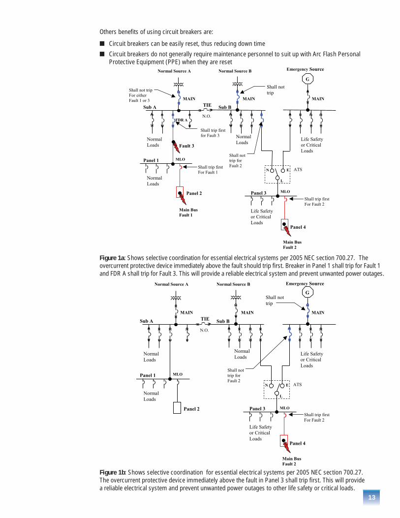
For main bus Fault 1 in Figure 1a, the overcurrent device downstream in Panel 1, and closest to the fault,should operate and isolate the rest of the system from the event. If the downstream device doesn'toperate, and the upstream overcurrent device FDR A trips, then all the loads in Panel 1 are lost andunwanted outages occur. The same for Fault 3, if the main breaker in Sub A trips instead of thedownstream FDR A, all the loads will be lost in Sub A. This is the main emphasis for the 2005 NECregulations for essential electrical systems in Healthcare facilities.
For main bus Fault 2 in Figures 1a and 1b, the overcurrent device in Panel 3 has to coordinate with boththe Normal Source B and the emergency source. Regardless which source is operating, the system musthave selective coordination. If the upstream feeder or main in either Sub B or emergency switchgear tripbefore the branch breaker in Panel 3, there will be a severe outage. Essential electrical systems will be lostand patients’ lives in surgery, emergency rooms, coronary care, intensive care, etc. could be in danger.
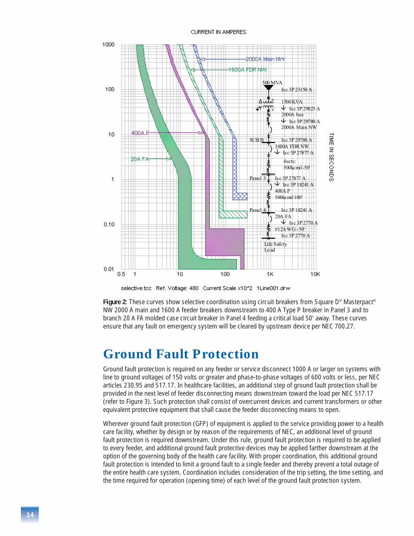
The following time overcurrent coordination curves (shown in Figure 2) show proper selectivity per theNEC, using circuit breakers in Sub B, Panel 3, and Panel 4 from Figure 1a. The 20 A branch breaker curveshown in Figure 2 is the last protective device in Panel 4 serving the critical load. It is also the first breakerto trip on downstream faults.
Circuit breakers vs. fusesBoth fuses and circuit breakers can be used on hospital power systems when considering selectivecoordination. Choosing between using fuses or circuit breakers during the design of the hospital isusually the job of the consulting engineer or engineering and maintenance supervisor. Their power systemdesign must have selective coordination when feeding essential electrical loads. Outages in hospitals areserious events and getting power back on-line quickly and safely are the main concerns.
The following 2005 NFPA 99, Section 4.4 distribution design factors should be considered when choosingfuses over circuit breakers in hospital systems.
� Abnormal voltages such as single phasing of three-phase utilization equipment. Fused switches typicallydo not protect from single-phasing and this can cause damage to rotating equipment such as motors
� Capability of achieving the fastest possible restoration of any given circuit(s) after clearing a fault.Power cannot be restored unless spare fuses are available and the proper PPE equipment is worn.This can cause extensive outages
13
Others benefits of using circuit breakers are:
� Circuit breakers can be easily reset, thus reducing down time
� Circuit breakers do not generally require maintenance personnel to suit up with Arc Flash PersonalProtective Equipment (PPE) when they are reset
Figure 1a: Shows selective coordination for essential electrical systems per 2005 NEC section 700.27. Theovercurrent protective device immediately above the fault should trip first. Breaker in Panel 1 shall trip for Fault 1and FDR A shall trip for Fault 3. This will provide a reliable electrical system and prevent unwanted power outages.
Figure 1b: Shows selective coordination for essential electrical systems per 2005 NEC section 700.27. The overcurrent protective device immediately above the fault in Panel 3 shall trip first. This will provide a reliable electrical system and prevent unwanted power outages to other life safety or critical loads.
14
Figure 2: These curves show selective coordination using circuit breakers from Square D® Masterpact®
NW 2000 A main and 1600 A feeder breakers downstream to 400 A Type P breaker in Panel 3 and tobranch 20 A FA molded case circuit breaker in Panel 4 feeding a critical load 50' away. These curvesensure that any fault on emergency system will be cleared by upstream device per NEC 700.27.
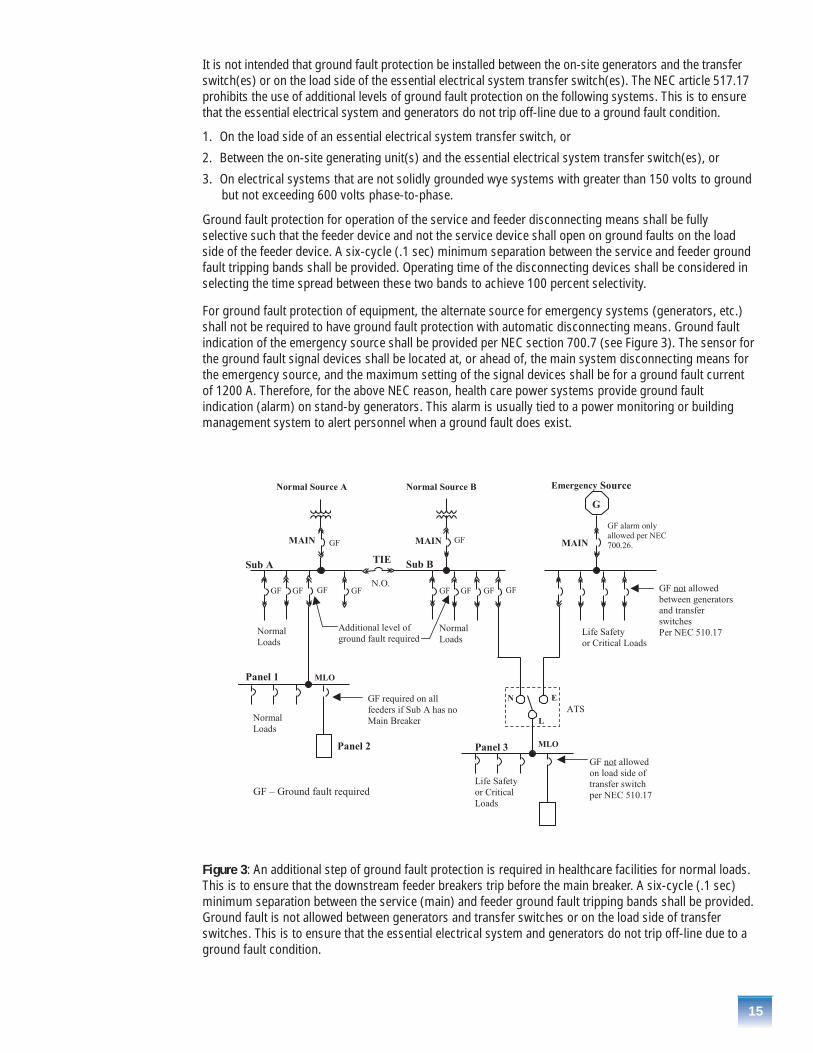
Ground Fault ProtectionGround fault protection is required on any feeder or service disconnect 1000 A or larger on systems withline to ground voltages of 150 volts or greater and phase-to-phase voltages of 600 volts or less, per NECarticles 230.95 and 517.17. In healthcare facilities, an additional step of ground fault protection shall beprovided in the next level of feeder disconnecting means downstream toward the load per NEC 517.17(refer to Figure 3). Such protection shall consist of overcurrent devices and current transformers or otherequivalent protective equipment that shall cause the feeder disconnecting means to open.
Wherever ground fault protection (GFP) of equipment is applied to the service providing power to a healthcare facility, whether by design or by reason of the requirements of NEC, an additional level of groundfault protection is required downstream. Under this rule, ground fault protection is required to be appliedto every feeder, and additional ground fault protective devices may be applied farther downstream at theoption of the governing body of the health care facility. With proper coordination, this additional groundfault protection is intended to limit a ground fault to a single feeder and thereby prevent a total outage ofthe entire health care system. Coordination includes consideration of the trip setting, the time setting, andthe time required for operation (opening time) of each level of the ground fault protection system.
15
It is not intended that ground fault protection be installed between the on-site generators and the transferswitch(es) or on the load side of the essential electrical system transfer switch(es). The NEC article 517.17prohibits the use of additional levels of ground fault protection on the following systems. This is to ensurethat the essential electrical system and generators do not trip off-line due to a ground fault condition.
1. On the load side of an essential electrical system transfer switch, or
2. Between the on-site generating unit(s) and the essential electrical system transfer switch(es), or
3. On electrical systems that are not solidly grounded wye systems with greater than 150 volts to groundbut not exceeding 600 volts phase-to-phase.
Ground fault protection for operation of the service and feeder disconnecting means shall be fullyselective such that the feeder device and not the service device shall open on ground faults on the loadside of the feeder device. A six-cycle (.1 sec) minimum separation between the service and feeder groundfault tripping bands shall be provided. Operating time of the disconnecting devices shall be considered inselecting the time spread between these two bands to achieve 100 percent selectivity.
For ground fault protection of equipment, the alternate source for emergency systems (generators, etc.)shall not be required to have ground fault protection with automatic disconnecting means. Ground faultindication of the emergency source shall be provided per NEC section 700.7 (see Figure 3). The sensor forthe ground fault signal devices shall be located at, or ahead of, the main system disconnecting means forthe emergency source, and the maximum setting of the signal devices shall be for a ground fault currentof 1200 A. Therefore, for the above NEC reason, health care power systems provide ground faultindication (alarm) on stand-by generators. This alarm is usually tied to a power monitoring or buildingmanagement system to alert personnel when a ground fault does exist.
Figure 3: An additional step of ground fault protection is required in healthcare facilities for normal loads.This is to ensure that the downstream feeder breakers trip before the main breaker. A six-cycle (.1 sec)minimum separation between the service (main) and feeder ground fault tripping bands shall be provided.Ground fault is not allowed between generators and transfer switches or on the load side of transferswitches. This is to ensure that the essential electrical system and generators do not trip off-line due to aground fault condition.

N
Liquid TypeTransformers
MV PF Capacitors
Vacuum, Chilled water, AHUs, Boiler motors, and Cooling Tower,Supply and exhaust fans, etc.
Low Voltage PF Capacitors
Variable Speed Drives
Isolating and Harmonic Mitigating transformers
Lighting Control – PowerLink® TRLC
Plug-inRisers or Criti
MetalcladSwitchgear
4 PoleATS
480/277V
Dry Type Transformers
12.47kV MV Switchgear
Surge ProtectionNormal Power
LV Motor Control Center
16
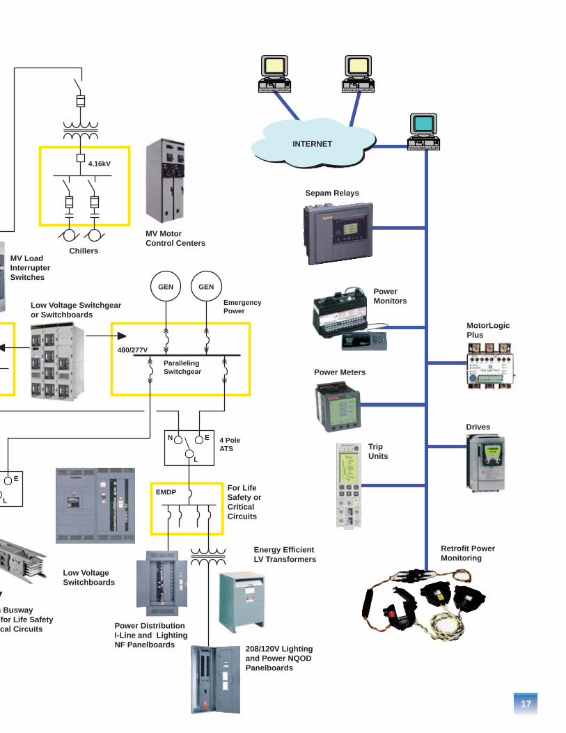
Typical Product One Line Diagram
E
L
N
n Busway for Life Safety cal Circuits
Low Voltage Switchboards
Power DistributionI-Line and LightingNF Panelboards 208/120V Lighting
and Power NQOD Panelboards
Energy EfficientLV Transformers
For Life Safety or Critical Circuits
Paralleling Switchgear
EmergencyPower
Sepam Relays
PowerMonitors
MotorLogic Plus
Drives
Retrofit Power Monitoring
Trip Units
Low Voltage Switchgearor Switchboards
MV Load Interrupter Switches
Chillers
MV Motor Control Centers
4.16kV
4 PoleATS
480/277V
E
L
EMDP
GEN GEN
INTERNET
Power Meters
17

18
Medium Voltage Product OfferingMetalclad™ SwitchgearMasterclad® medium voltage switchgear is used in a wide variety of switching, control and protectiveapplications for hospital. In large systems, it’s mainly used for the main incoming service equipment andthe generator paralleling gear. Auto transfer schemes allow Metalclad breakers to seamlessly switchbetween utility sources and paralleling gear during scheduled or uncontrolled power outages.
Metalclad switchgear is also used for the primary disconnect on the 12.47 kV to 480 V and 208 Vtransformers. This allows users to electrically transfer between two sources without the use ofgenerators. This is also important for isolating cable faults that may occur while in operation.
Significantly, most of the Masterclad switchgear specified for these applications is relied upon to providethe critical main service entrance protection and controls.
This class of switchgear protects transformers, generators and feeder circuits.
Benefits� Long life and minimum maintenance – Vacuum interrupter design is capable of 20 to 100 full fault
operations (varies by ratings), Total fault clearing time is 3 cycles. This is the fastest in the industryand reduces voltage sags on the system.
� Safety barriers and interlocks – Full compartmentalization is supplied with primary functionsseparated by grounded metal barriers. All bussing is insulated and live parts are not exposed. Safetyinterlocks work with the breaker racking system. These protective features provide safety foroperating personnel.
� Breakers can withstand various levels of commissioning which involves many switching operations.
Hospital Applications� Main service switchgear
� Paralleling switchgear
Ratings� 4.76 kV – 15 kV (to 13.8 kV nominal)
� 1200 A – 3000 A
� 250 MVA – 1000 MVA interrupting capacity
� 60 kV and 95 kV BIL
� Indoor and outdoor enclosures
Standard Features (as defined by ANSI C37.20.2)� Removable (drawout) circuit breaker
� Fully compartmented construction
� Grounded metal barriers enclose all live parts
� Automatic shutters
� Insulated bus
� Mechanical interlocks
� Disconnect type voltage transformers – CPT and VTs
� Grounded breaker truck in and between test/disconnected and connected positions
� Low voltage instrument/control compartment isolated from primary voltage areas

19
Arc TerminatorMedium voltage switchgear can have an additional degree of protection from damaging open arcing faultswith the Arc terminator arc extinguishing system. This system detects and controls the effects of arcing faults.It extinguishes arcs rapidly, significantly minimizing equipment damage and reducing equipment downtime.
Benefits� Confines the effects of the arc to the point of initiation
� Enhances protection by detecting and commuting arc fault current
� Extinguishes high magnitude arc currents within less than 1/4 of a cycle and prevents the buildup of high internal pressures
Features� Uses sensors to detect arcs in medium voltage switchgear
� Initiates the closing of a high-speed vacuum switch if an arc is detected via the electronic control unit
� Uses two sensing inputs:� Optical sensors detect arcing faults� Current transformers are used to detect any change in current (both input events must occur
together to operate the high-speed switch)� The Arc Terminator system can be shipped with any new switchgear lineup
� Easy to install and operate: no settings or other calculations required during switchgear installation
� Switchgear protective relaying functions are coordinated to provide maximum protection with theaddition of the Arc Terminator system
How it works
The Arc Terminator system confines the effects of an arcing fault to the point of initiation. When an arc isdetected, a high speed vacuum switch closes, effectively crow-baring the short circuit. This action createsa solid conducting path for the current parallel with the arc. The open burning arc is extinguished,preventing the buildup of damaging pressures. The energy released by the arcing fault is significantlyreduced. The electronic control requires two sensing inputs: (1) optical sensors to detect arcing faultsand (2) current sensors to detect changes in the current waveform.
An indicator on the junction box (which serves as a collector for the optical inputs), points to thecompartment where the arcing fault occurred, making it easy to pinpoint the location of a fault and repairthe problem quickly. Once the cause of the fault has been fixed, the system is ready to be reset andreturned to normal operation. For critical applications such as large hospitals and healthcare complexesthis means less downtime.
Metal Enclosed Switchgear Metal enclosed interrupter switches are most often used in hospitals for protecting medium voltagetransformers that service low voltage (480 V and 208 V) switchgear. The load interrupter switches arealso useful for isolating cables between Metalclad™ breakers and transformers when maintenance isrequired. This equipment is ideal for applications where high duty cycle operation (switching) is notrequired and equipment cost is a concern.
Hospital Application� Primary protection (fusible) and isolation (non-fused) for medium voltage transformers
HVL/cc™ switchgear features – 2.4 kV to 38 kV switching, control, and overload protection are ideal forhospital applications. Improving reliability and performance are the primary goals of switchgear in anyswitching, control or protective application.

20
Medium Voltage Motor Control CentersMotorpact medium voltage motor control centers are normally used to supply and protect large chillermotors 200 HP and above in hospitals. Feeding large motors with lower voltages becomes costprohibitived because equipment sizes get very large, limited, or unavailable and multiple sets of conduitand cable are needed.
Our Motorpact is designed and manufactured to meet your power and chiller control challenges. Ourmotor controllers feature industry-first innovations that provide unmatched performance, high reliability,low maintenance and exclusive technologies. Our different motor controllers available are listed below.
Full Voltage Controller
This controller is used for full-voltage starting and stopping of AC motor applications at 2300 V and aboveand provides the following.
� Motor overload and short circuit protection in one package
� Incoming line connection
� Control power transformer (115 volt secondary)
� Magnetic three-pole vacuum contactor (mechanically latched types are also available)
� Run-test circuit
Reduced Voltage Auto-transformer Controller
This type of controller is typically used to start very large motors that may cause a voltage drop on therest of the power system. It also helps with reducing the size of medium voltage transformers needed forthese applications.
� Available from 2300 V to 7200 V with ranges of horsepower up to 5000 HP
� Provides the highest torque per ampere of line current
� Features an inherently closed transition type, to full voltage running
� Features voltage taps, which permit the adjustment of starting voltage, allowing the customer to adjustthe starting voltage to suit the system capabilities and limit voltage sags on the power system
� Offers acceleration times up to 30 seconds for medium duty, making it suitable for a long starting period
We’ve taken these goals further with HVL/cc medium voltage metal enclosed switchgear. Its exclusiveoperational features offer a higher level of system protection, yet it also incorporates innovative designfeatures that reduce the risk of costly maintenance problems. The major differentiating features of HVL/ccswitchgear include:
� Smallest footprint in the industry (approximately one-quarter size of traditional medium voltage metalenclosed switchgear) – makes it ideal for retrofit applications requiring increased load or duplexswitches. Compact footprint fits easily through standard doorways
� Compartmentalized construction – the fuse/cable compartment is isolated from the main bus, whilethe main switch contacts are housed in a sealed interrupter
� Low maintenance – Sealed for life interruption saves time and expense with maintenance-free maincontacts and ground switch contacts. Prevents switch contamination especially in harsh environments
� Fault-making grounding switch (optional) – prevents access to “hot” fuse/cable compartment with mechanical interlock
� Front access – eliminates need for service space behind switchgear
� FuseLogic system – provides single-phase protection and blown fuse indication. This protectsdownstream motors from overheating due to negative sequence currents
No other medium voltage metal enclosed switchgear on the market offers these advantages. When youmake the comparison based on installation simplicity, performance, and total cost of ownership, HVL/ccswitchgear becomes the clear choice for system protection and reliability.
21
Medium Voltage Reduced Voltage Soft Start Controller
This type of controller is typically used to start large motors that have special load conditionsapplications. Motorpact reduced voltage soft start (RVSS) motor control units provide:
� Pre-engineered, integrated motor control package for reduced voltage starting and soft stopping
� Allows customer to fine-tune the starting parameters to meet a wide variety of unique load conditionsand to prevent voltage sags on the power system
� Offers a better alternative to traditional reactor or auto-transformer type reduced voltage starters
� Reduces voltage drop on the system while starting
� Allows the use of smaller medium voltage transformers for this application
Transparent Ready® Motorpact™ motor controllers allow users to view meter readings in real-time, withouthaving to walk the entire facility. Plus, users can access a running minimum/maximum history, which canhelp users spot abnormal conditions.
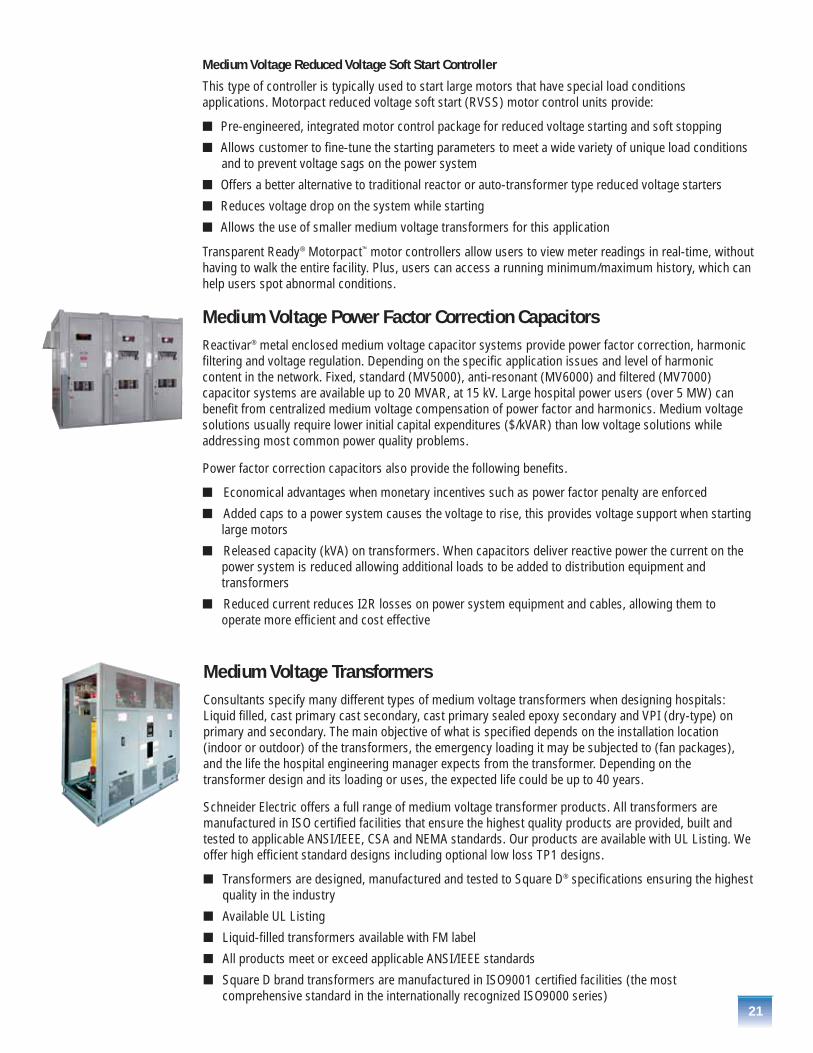
Medium Voltage Power Factor Correction CapacitorsReactivar® metal enclosed medium voltage capacitor systems provide power factor correction, harmonicfiltering and voltage regulation. Depending on the specific application issues and level of harmoniccontent in the network. Fixed, standard (MV5000), anti-resonant (MV6000) and filtered (MV7000)capacitor systems are available up to 20 MVAR, at 15 kV. Large hospital power users (over 5 MW) canbenefit from centralized medium voltage compensation of power factor and harmonics. Medium voltagesolutions usually require lower initial capital expenditures ($/kVAR) than low voltage solutions whileaddressing most common power quality problems.
Power factor correction capacitors also provide the following benefits.
� Economical advantages when monetary incentives such as power factor penalty are enforced
� Added caps to a power system causes the voltage to rise, this provides voltage support when starting large motors
� Released capacity (kVA) on transformers. When capacitors deliver reactive power the current on thepower system is reduced allowing additional loads to be added to distribution equipment andtransformers
� Reduced current reduces I2R losses on power system equipment and cables, allowing them tooperate more efficient and cost effective
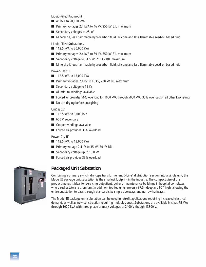
Medium Voltage Transformers Consultants specify many different types of medium voltage transformers when designing hospitals:Liquid filled, cast primary cast secondary, cast primary sealed epoxy secondary and VPI (dry-type) onprimary and secondary. The main objective of what is specified depends on the installation location(indoor or outdoor) of the transformers, the emergency loading it may be subjected to (fan packages),and the life the hospital engineering manager expects from the transformer. Depending on thetransformer design and its loading or uses, the expected life could be up to 40 years.
Schneider Electric offers a full range of medium voltage transformer products. All transformers aremanufactured in ISO certified facilities that ensure the highest quality products are provided, built andtested to applicable ANSI/IEEE, CSA and NEMA standards. Our products are available with UL Listing. Weoffer high efficient standard designs including optional low loss TP1 designs.
� Transformers are designed, manufactured and tested to Square D® specifications ensuring the highestquality in the industry
� Available UL Listing
� Liquid-filled transformers available with FM label
� All products meet or exceed applicable ANSI/IEEE standards
� Square D brand transformers are manufactured in ISO9001 certified facilities (the mostcomprehensive standard in the internationally recognized ISO9000 series)
22
Liquid-Filled Padmount� 45 kVA to 20,000 kVA
� Primary voltages 2.4 kVA to 46 kV, 250 kV BIL maximum
� Secondary voltages to 25 kV
� Mineral oil, less flammable hydrocarbon fluid, silicone and less flammable seed-oil based fluid
Liquid-Filled Substations� 112.5 kVA to 20,000 kVA
� Primary voltages 2.4 kVA to 69 kV, 350 kV BIL maximum
� Secondary voltage to 34.5 kV, 200 kV BIL maximum
� Mineral oil, less flammable hydrocarbon fluid, silicone and less flammable seed-oil based fluid
Power-Cast® II� 112.5 kVA to 13,000 kVA
� Primary voltages 2.4 kV to 46 kV, 200 kV BIL maximum
� Secondary voltage to 15 kV
� Aluminum windings available
� Forced air provides 50% overload for 1000 kVA through 5000 kVA, 33% overload on all other kVA ratings
� No pre-drying before energizing
UniCast II™
� 112.5 kVA to 3,000 kVA
� 600 V secondary
� Copper windings available
� Forced air provides 33% overload
Power Dry II™
� 112.5 kVA to 13,000 kVA
� Primary voltage 2.4 kV to 35 kV150 kV BIL
� Secondary voltage up to 15.0 kV
� Forced air provides 33% overload
Packaged Unit SubstationCombining a primary switch, dry-type transformer and I-Line® distribution section into a single unit, theModel III package unit substation is the smallest footprint in the industry. The compact size of thisproduct makes it ideal for servicing outpatient, boiler or maintenance buildings in hospital complexeswhere real estate is a premium. In addition, top fed units are only 37.5'' deep and 90'' high, allowing theentire substation to pass through standard size single doorways and narrow hallways.
The Model III package unit substation can be used in retrofit applications requiring increased electricaldemand, as well as new construction requiring multiple zones. Substations are available in sizes 75 kVAthrough 1000 kVA with three phase primary voltages of 2400 V though 13800 V.
23
Power Monitoring and NetworkCommunications ProductsA typical modern hospital utilizes networks for patient accounts, building management, powermanagement and lighting control systems, while operating an interoffice or corporate Ethernetinformation network. Many times, these networks employ different communication protocols as well asdifferent physical wiring and interface equipment. Each of these systems provides critical information forefficient facility operation, but blocks interoperability of the separate systems. Managing separatenetworks for each facility system requires resources, experience, extensive support and continuoustraining. These activities increase operating costs and decrease facility efficiency and reliability.
Schneider Electric’s policy for networks is based on open standards in order to ensure open connectivityfor our customers. The Transparent Ready® family of products emphasizes Ethernet and web technologies(TCP/IP, HTTP, XML, etc.). Modbus®, a defacto protocol standard in many markets, continues to play acentral role in our network policy as the main messaging protocol, whether it’s at the Ethernet level overTCP/IP (“Modbus TCP”) or over RS-485 multi-point communications (“Modbus RTU” or “Modbus serial”).
Implementing web-based technologies on Ethernet provides an extremely flexible communicationsinfrastructure. Utilizing common technologies and infrastructure allows shorter design cycles, lowerimplementation costs, and lower maintenance costs, and provides for continuous process improvement.Utilizing the power of web technologies like TCP/IP provides an open path to information and controlsystems on a facility’s existing Ethernet network. This approach provides all the benefits of a secure anddeterministic architecture without locking into proprietary networks and protocols. Combining thosebenefits provides unmatched real-time control and open access to critical systems information withoutthe restrictions of proprietary environments or the threat of implementing a field bus that may not exist ina few years. Hospital engineering and maintainence managers can fully integrate data from many systemswithin their facilities and be able to better manage their efficiencies.
Transparent Ready® Equipment
Schneider Electric is the first manufacturer in the world to provide Ethernet connectivity across ourcomprehensive portfolio of power distribution equipment. We call this innovative technology platformTransparent Ready Equipment. It’s simply the easiest and most open solution for accessing informationabout your hospital electrical systems.
All Transparent Ready Equipment products feature an Ethernet connection and embedded web server,designed to organize valuable information for easy access from any computer on your network using anystandard web browser. By making it simple to connect your power equipment, we help you get theactionable information you need to reduce costs, and increase productivity.
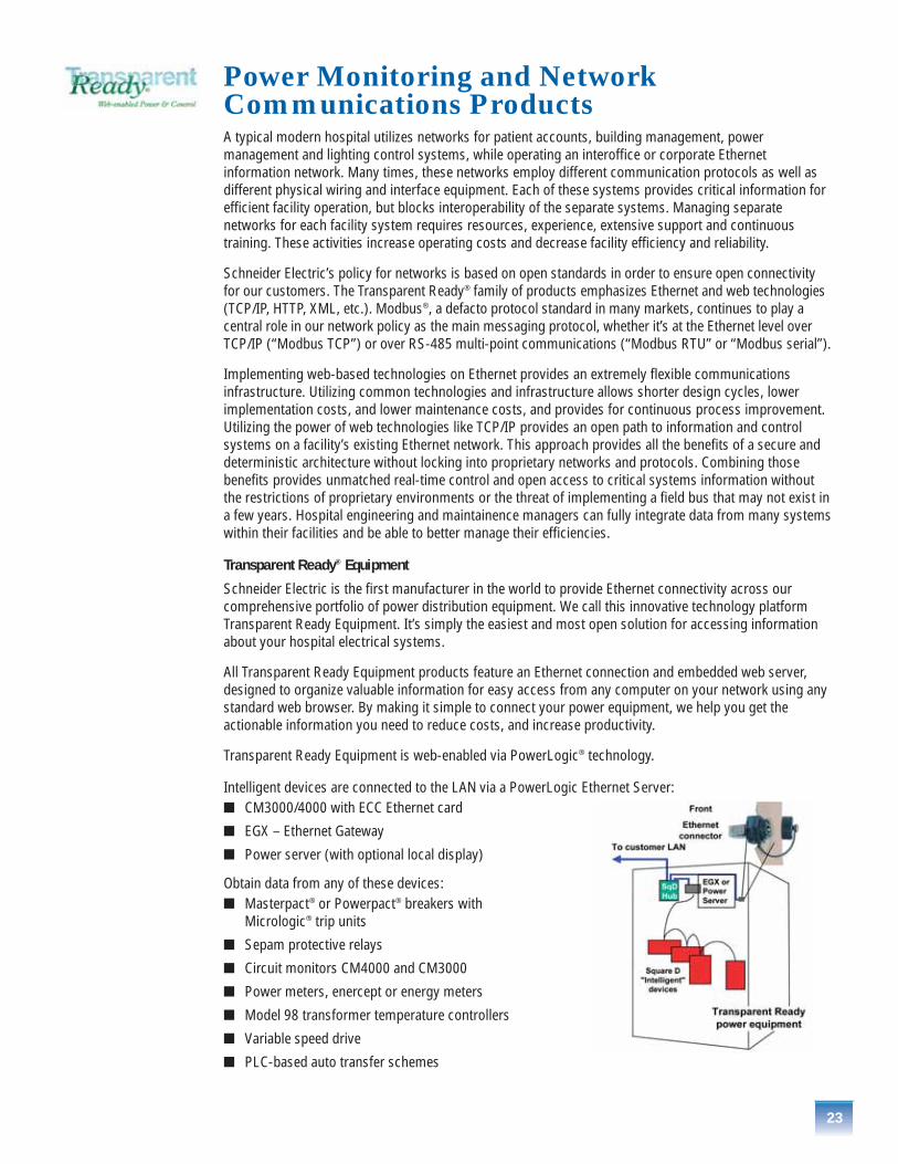
Transparent Ready Equipment is web-enabled via PowerLogic® technology.
Intelligent devices are connected to the LAN via a PowerLogic Ethernet Server:� CM3000/4000 with ECC Ethernet card
� EGX – Ethernet Gateway
� Power server (with optional local display)
Obtain data from any of these devices:� Masterpact® or Powerpact® breakers with
Micrologic® trip units
� Sepam protective relays
� Circuit monitors CM4000 and CM3000
� Power meters, enercept or energy meters
� Model 98 transformer temperature controllers
� Variable speed drive
� PLC-based auto transfer schemes
Power MonitoringMany hospital engineering and maintenance managers have reached the same conclusion about their electrical power systems. By employing sophisticated power monitoring equipment to analyze historicaland real-time data, they can reduce the cost of electricity and improve its quality and reliability andenhance their troubleshooting abilities.
Intelligent analysis of power data prevents electrical system problems and saves money. Below are someof these benefits from a power monitoring system.
� Better understanding of electrical system loading and demand. This helps cut capital cost from overdesigning when expansions or modifications are needed
� Easy to compare electric bills (kWHs) with utility company statements
� Catch voltage sags and disturbances that may be causing critical equipment to trip off-line such as UPSs or variable speed drives
� Easier to troubleshoot system problems such as faults or harmonics
� Helps provide a better understanding of entire electrical system
24
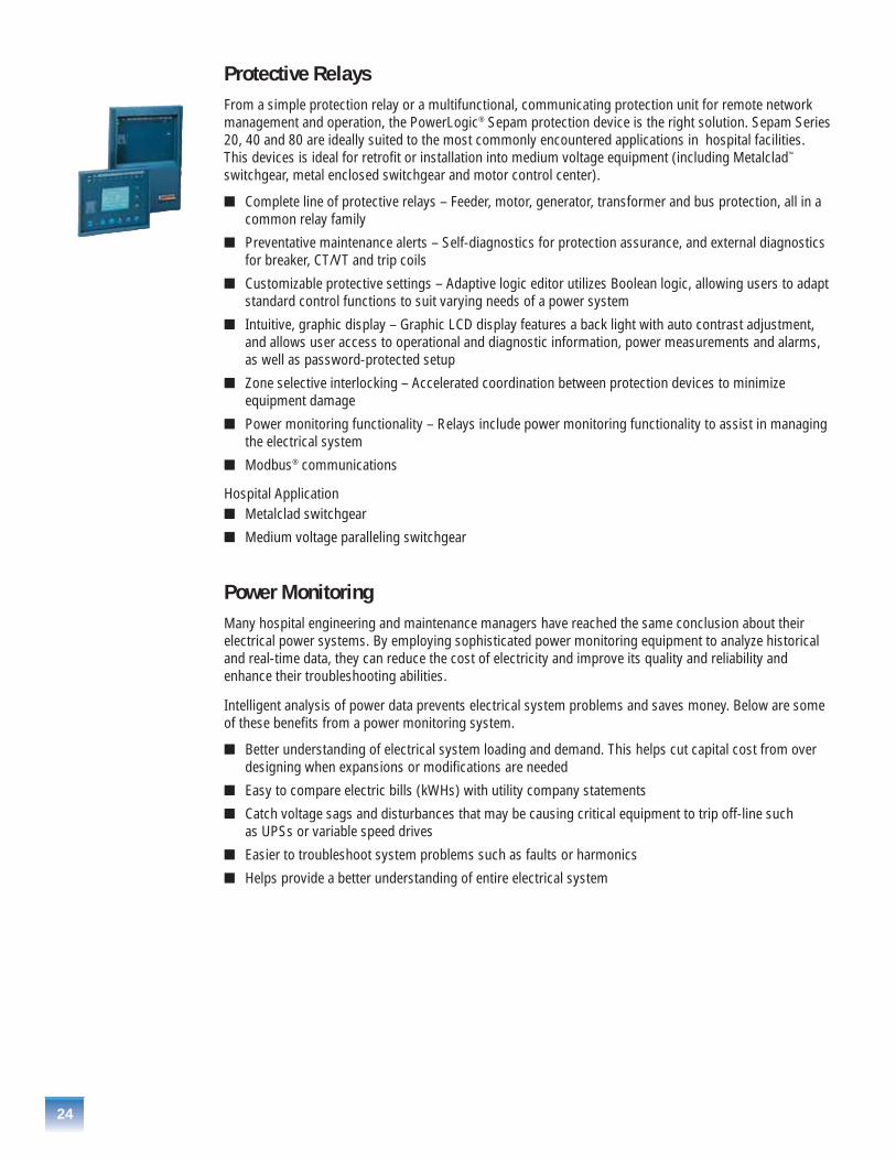
Protective Relays From a simple protection relay or a multifunctional, communicating protection unit for remote networkmanagement and operation, the PowerLogic® Sepam protection device is the right solution. Sepam Series20, 40 and 80 are ideally suited to the most commonly encountered applications in hospital facilities.This devices is ideal for retrofit or installation into medium voltage equipment (including Metalclad™
switchgear, metal enclosed switchgear and motor control center).
� Complete line of protective relays – Feeder, motor, generator, transformer and bus protection, all in a common relay family
� Preventative maintenance alerts – Self-diagnostics for protection assurance, and external diagnosticsfor breaker, CT/VT and trip coils
� Customizable protective settings – Adaptive logic editor utilizes Boolean logic, allowing users to adaptstandard control functions to suit varying needs of a power system
� Intuitive, graphic display – Graphic LCD display features a back light with auto contrast adjustment,and allows user access to operational and diagnostic information, power measurements and alarms,as well as password-protected setup
� Zone selective interlocking – Accelerated coordination between protection devices to minimize equipment damage
� Power monitoring functionality – Relays include power monitoring functionality to assist in managing the electrical system
� Modbus® communications
Hospital Application� Metalclad switchgear
� Medium voltage paralleling switchgear
25
Power MetersPower meters are typically used on feeder breakers for medium voltage switchgear and low voltageswitchgear or switchboards. They are also used downstream on low voltage motor control centers andpower distribution switchboards and panelboards. These devices have become very powerful and providemore monitoring capabilities than circuit monitors manufactured in the late 90s. Below are some of thefeatures of power meters.
� Basic metering functions, allowing metering of current, volts, power, energy and demand readings
� Power quality readings include total harmonic distortion for current and voltage readings
� Min/max values
� Alarm/relay functions
� Event and data logging on pre-configured values
� Ethernet communications available via Transparent Ready®
Hospital Application� Motor control centers
� Distribution switchboards
� Panelboards
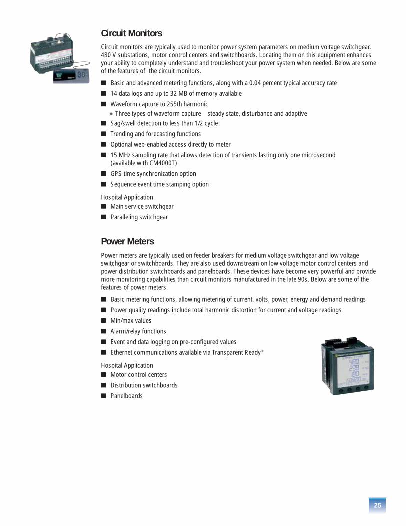
Circuit MonitorsCircuit monitors are typically used to monitor power system parameters on medium voltage switchgear,480 V substations, motor control centers and switchboards. Locating them on this equipment enhancesyour ability to completely understand and troubleshoot your power system when needed. Below are someof the features of the circuit monitors.
� Basic and advanced metering functions, along with a 0.04 percent typical accuracy rate
� 14 data logs and up to 32 MB of memory available
� Waveform capture to 255th harmonic � Three types of waveform capture – steady state, disturbance and adaptive
� Sag/swell detection to less than 1/2 cycle
� Trending and forecasting functions
� Optional web-enabled access directly to meter
� 15 MHz sampling rate that allows detection of transients lasting only one microsecond (available with CM4000T)
� GPS time synchronization option
� Sequence event time stamping option
Hospital Application� Main service switchgear
� Paralleling switchgear
26
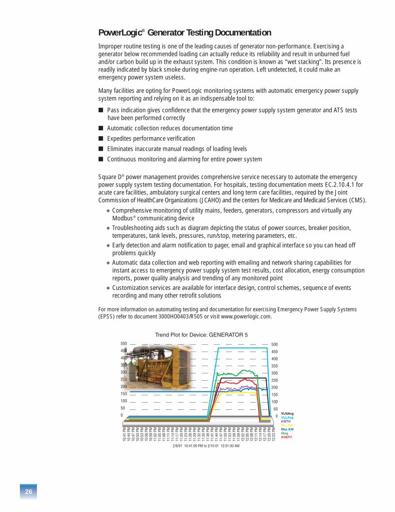
PowerLogic® Generator Testing DocumentationImproper routine testing is one of the leading causes of generator non-performance. Exercising agenerator below recommended loading can actually reduce its reliability and result in unburned fueland/or carbon build up in the exhaust system. This condition is known as “wet stacking”. Its presence isreadily indicated by black smoke during engine-run operation. Left undetected, it could make anemergency power system useless.
Many facilities are opting for PowerLogic monitoring systems with automatic emergency power supplysystem reporting and relying on it as an indispensable tool to:
� Pass indication gives confidence that the emergency power supply system generator and ATS testshave been performed correctly
� Automatic collection reduces documentation time
� Expedites performance verification
� Eliminates inaccurate manual readings of loading levels
� Continuous monitoring and alarming for entire power system
Square D® power management provides comprehensive service necessary to automate the emergencypower supply system testing documentation. For hospitals, testing documentation meets EC.2.10.4.1 foracute care facilities, ambulatory surgical centers and long term care facilities, required by the JointCommission of HealthCare Organizations (JCAHO) and the centers for Medicare and Medicaid Services (CMS).
� Comprehensive monitoring of utility mains, feeders, generators, compressors and virtually anyModbus® communicating device
� Troubleshooting aids such as diagram depicting the status of power sources, breaker position,temperatures, tank levels, pressures, run/stop, metering parameters, etc.
� Early detection and alarm notification to pager, email and graphical interface so you can head offproblems quickly
� Automatic data collection and web reporting with emailing and network sharing capabilities forinstant access to emergency power supply system test results, cost allocation, energy consumptionreports, power quality analysis and trending of any monitored point
� Customization services are available for interface design, control schemes, sequence of eventsrecording and many other retrofit solutions
For more information on automating testing and documentation for exercising Emergency Power Supply Systems(EPSS) refer to document 3000HO0403/R505 or visit www.powerlogic.com.

27
Low Voltage Product OfferingSchneider Electric offers a wide variety of low voltage power distribution products, from our QED-2Powerstyle™ switchboards using group-mounted I-Line® construction to our QED-6 compartmentalizedswitchboards. Schneider Electric provides a complete UL offering. Power-Zone® 4 switchgear is built tostrict ANSI standards and features the industry preferred Masterpact® NW and NT circuit breakers.
Transparent Ready® communications technology with PowerLogic® components is offered throughout thefull range of low voltage distribution equipment. All Transparent Ready products feature an Ethernetconnection and embedded web server, designed to organize valuable information for easy access fromany computer on your network using any standard web browser. By making it simple to connect yourpower and control equipment, we help you get the actionable information you need to reduce costs, andincrease productivity.
These products and components are the preferred choice for many end users, consultants andcontractors. They are used by many of the leading specialty OEMs sub-systems such as parallelingswitchgear and UPS equipment.
Low Voltage Switchgear Power-Zone 4 with Masterpact Circuit Breakers and PowerLogic Monitoring
One of the major benefits for using ANSI-rated switchgear is the structure and breakers have definedshort time withstand ratings (short circuit current withstand for 30 cycles). When properly adjusted, thisallows main and feeder breakers to coordinate with downstream protective devices to ensure the deviceclosest to the fault clears first. This is very important when trying to selectively coordinate withdownstream feeder breakers or other devices downstream. In addition to short time withstand ratings,other benefits such as 100% rated breakers (from 800 A to 5000 A frames), drawout construction, andmaintainability for extended life make Power-Zone 4 switchgear the primary choice in hospitals.
Hospital Application� Main service switchgear
� Paralleling switchgear
Major new design and operational features have also been built into the Power-Zone 4 switchgearstructures, for longer life and increased reliability. Below is a list of product features.
� Smallest footprint in the industry
� Masterpact circuit breakers have higher short time ratings and interrupting ratings than competitiveproducts and met ANSI specified number of operations with no maintenance required
� Electrically operated breakers are listed to UL 1066, and the structure is listed to UL 1558
� 200 kA SCCR without fuses
� Increased wire bending space
� Available up to 5000 A bus rating
� Micrologic® trip units with power monitoring, control and communications

28
� Optional PLC based auto transfer schemes
� Optional Transparent Ready® communications utilizing PowerLogic® technology
� Optional Surgelogic® TVSS
� Differential ground fault option for 4W systems with multiple sources
� Arc flash application options� Arc flash limiting feeder breakers up to 2000 A reduce arc incident energy on downstream
equipment such as MCCs and PDPs� Thru-the-door breaker operation allows unit to be operated/racked while door is closed; this reduces
NFPA 70E PPE category by one level� Rear-hinged doors allow easy access to cables; this reduces NFPA 70E 2004 PPE category by one level
Benefits of using Power-Zone® 4 in hospital applications:
� Drawout construction is required for quick circuit breaker change-out
� Transfer system requirements call for circuit breakers to close within five-cycles and stored energycircuit breakers are required for reliability
� Front access to control wires is desired for ease of installation, maintenance and upgrade
� Circuit breaker compartmentalization is required for system integrity
� Segregation of circuit breaker compartments, from bus and cable compartments, is required for equipment
� Isolation breakers without fuses are required for high short circuit current ratings up to 200 kAIR
Switchboards – Rear Connected QED-6 with Masterpact® Circuit Breakersand PowerLogic® MonitoringRear connected switchboards offer many of the same benefits of ANSI rated switchgear listed above.Short times withstand ratings on the breakers, and structures as well as high short circuit interruptingratings. Lower equipment cost, drawout breakers (breaker frame sizes to 250 A to 5000 A) andmaintainability for extended life are reasons this product is used in these facilities.
Hospital Application� Main service switchgear
� Paralleling switchgear
QED-6 switchboard structures offer many of the same benefits as Power-Zone 4 switchgear. Some ofthese features differences are listed below.
� Masterpact and PowerPact® circuit breakers have higher short time ratings and interrupting ratingsthan competitive products
� Up to eight Masterpact NT circuit breakers can be mounted in a single 30"-wide section
� PowerPact circuit breakers 250 A and 600 A frame for smaller loads
� Electrically operated breakers UL 489 rated and structure UL 891 listed
� 150 kA SCCR without fuses @ 480 V (200 kAIR @ 240 V)
29
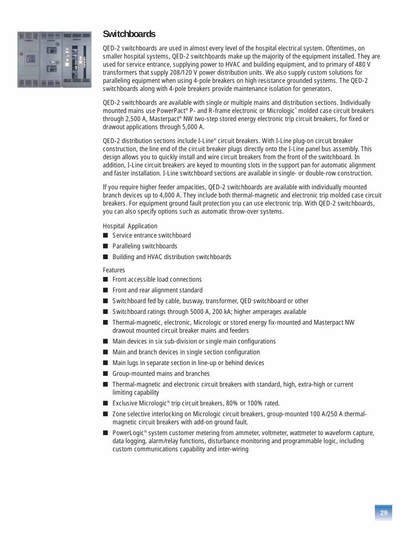
SwitchboardsQED-2 switchboards are used in almost every level of the hospital electrical system. Oftentimes, onsmaller hospital systems, QED-2 switchboards make up the majority of the equipment installed. They areused for service entrance, supplying power to HVAC and building equipment, and to primary of 480 Vtransformers that supply 208/120 V power distribution units. We also supply custom solutions forparalleling equipment when using 4-pole breakers on high resistance grounded systems. The QED-2switchboards along with 4-pole breakers provide maintenance isolation for generators.
QED-2 switchboards are available with single or multiple mains and distribution sections. Individuallymounted mains use PowerPact® P- and R-frame electronic or Micrologic® molded case circuit breakersthrough 2,500 A, Masterpact® NW two-step stored energy electronic trip circuit breakers, for fixed ordrawout applications through 5,000 A.
QED-2 distribution sections include I-Line® circuit breakers. With I-Line plug-on circuit breakerconstruction, the line end of the circuit breaker plugs directly onto the I-Line panel bus assembly. Thisdesign allows you to quickly install and wire circuit breakers from the front of the switchboard. Inaddition, I-Line circuit breakers are keyed to mounting slots in the support pan for automatic alignmentand faster installation. I-Line switchboard sections are available in single- or double-row construction.
If you require higher feeder ampacities, QED-2 switchboards are available with individually mountedbranch devices up to 4,000 A. They include both thermal-magnetic and electronic trip molded case circuitbreakers. For equipment ground fault protection you can use electronic trip. With QED-2 switchboards,you can also specify options such as automatic throw-over systems.
Hospital Application� Service entrance switchboard
� Paralleling switchboards
� Building and HVAC distribution switchboards
Features� Front accessible load connections
� Front and rear alignment standard
� Switchboard fed by cable, busway, transformer, QED switchboard or other
� Switchboard ratings through 5000 A, 200 kA; higher amperages available
� Thermal-magnetic, electronic, Micrologic or stored energy fix-mounted and Masterpact NW drawout mounted circuit breaker mains and feeders
� Main devices in six sub-division or single main configurations
� Main and branch devices in single section configuration
� Main lugs in separate section in line-up or behind devices
� Group-mounted mains and branches
� Thermal-magnetic and electronic circuit breakers with standard, high, extra-high or current limiting capability
� Exclusive Micrologic® trip circuit breakers, 80% or 100% rated.
� Zone selective interlocking on Micrologic circuit breakers, group-mounted 100 A/250 A thermal-magnetic circuit breakers with add-on ground fault.
� PowerLogic® system customer metering from ammeter, voltmeter, wattmeter to waveform capture,data logging, alarm/relay functions, disturbance monitoring and programmable logic, includingcustom communications capability and inter-wiring

30
� Custom engineering including main-tie-mains, multiple sets of through bus, reduced height and engineered houses
� 4-pole breakers are optional
� Transfer switches are optional
� Automatic throw-over systems are optional
PanelboardsEngineering and maintenance managers, engineering consultants and contractors prefer Square D® I-Line® NF and NQOD panelboards for use in hospital applications because these products are widelyrecognized as the industry leaders in reliability and versatility.
600 V Panelboards – I-Line®
Hospital Applications� Paralleling panelboards
� Cafeteria equipment
� Building and HVAC distribution panels
Main Breaker Panelboards� Accept a maximum 1200 A, thermal magnetic 80% or 100% rated electronic main and
branch breakers
� Available factory-assembled or merchandised
� Factory-assembled main circuit breaker interiors are available bottom-feed or top-feed
� Available with a short circuit current rating (SCCR) up to 200 kA maximum (100 kA @ 600 VAC) whensupplied by an I-Limiter® circuit breaker
� Available with a silver-plated or tin-plated copper bus or tin-plated aluminum bus
� Solid neutral is mounted in the main compartment with the main circuit breaker
Main Lugs Only Panelboards� Available with main lug only interiors rated up to 1200 A
� Accept a maximum 1200 A, thermal magnetic 80% or 100% rated electronic branch breakers
� Available factory-assembled or merchandised
� Available with a short circuit current rating (SCCR) up to 200 kA maximum (100 kA @ 600 VAC) whensupplied by an I-Limiter circuit breaker
� Available with a silver-plated or tin-plated copper bus or tin-plated aluminum bus
� Solid neutral is mounted in the main compartment with the main lugs
� Hinged cover, isolated main lugs compartment
� Main lug interiors are available as top-feed or bottom-feed
I-Line Plug-on Unit with Surgelogic® TVSS� Plug-on design requires less cable and conduit than end gutter-mounted TVSS unit, saving labor time
and material costs
� Bus-connected design enhances performance
� Integrated TVSS and circuit breaker disconnect feature compact design, requiring only 13.50" (343 mm) of branch mounting space
� SCCR up to 200 kA rating (100 kA @ 600 VAC) meets a wide variety of customer applications
31
I-Line® Circuit Breakers� I-Line panelboards are designed to accept the following circuit breakers: FY, FA, FH, FC, FJ, FK, FI, HD,
HG, HJ, HL, QB, QD, QG, QJ, QO, KA, KH, KC, KI, JD, JG, JJ, JL, LA, LH, LC, LI, LE, LX, LXI, MG, MJ,PG, PJ, PL, RG, RJ and RL
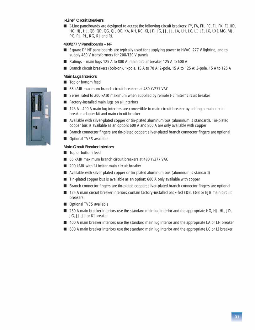
480/277 V Panelboards – NF� Square D® NF panelboards are typically used for supplying power to HVAC, 277 V lighting, and to
supply 480 V transformers for 208/120 V panels.
� Ratings – main lugs 125 A to 800 A, main circuit breaker 125 A to 600 A
� Branch circuit breakers (bolt-on), 1-pole, 15 A to 70 A; 2-pole, 15 A to 125 A; 3-pole, 15 A to 125 A
Main Lugs Interiors� Top or bottom feed
� 65 kAIR maximum branch circuit breakers at 480 Y/277 VAC
� Series rated to 200 kAIR maximum when supplied by remote I-Limiter® circuit breaker
� Factory-installed main lugs on all interiors
� 125 A - 400 A main lug interiors are convertible to main circuit breaker by adding a main circuitbreaker adapter kit and main circuit breaker
� Available with silver-plated copper or tin-plated aluminum bus (aluminum is standard). Tin-platedcopper bus is available as an option; 600 A and 800 A are only available with copper
� Branch connector fingers are tin-plated copper; silver-plated branch connector fingers are optional
� Optional TVSS available
Main Circuit Breaker Interiors� Top or bottom feed
� 65 kAIR maximum branch circuit breakers at 480 Y/277 VAC
� 200 kAIR with I-Limiter main circuit breaker
� Available with silver-plated copper or tin-plated aluminum bus (aluminum is standard)
� Tin-plated copper bus is available as an option; 600 A only available with copper
� Branch connector fingers are tin-plated copper; silver-plated branch connector fingers are optional
� 125 A main circuit breaker interiors contain factory-installed back-fed EDB, EGB or EJB main circuitbreakers
� Optional TVSS available
� 250 A main breaker interiors use the standard main lug interior and the appropriate HG, HJ, HL, JD,JG, JJ, JL or KI breaker
� 400 A main breaker interiors use the standard main lug interior and the appropriate LA or LH breaker
� 600 A main breaker interiors use the standard main lug interior and the appropriate LC or LI breaker
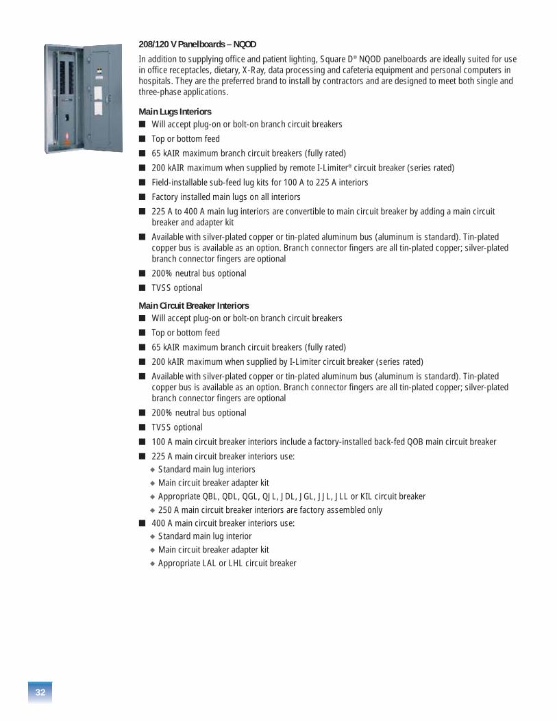
32
208/120 V Panelboards – NQOD
In addition to supplying office and patient lighting, Square D® NQOD panelboards are ideally suited for usein office receptacles, dietary, X-Ray, data processing and cafeteria equipment and personal computers in hospitals. They are the preferred brand to install by contractors and are designed to meet both single and three-phase applications.
Main Lugs Interiors� Will accept plug-on or bolt-on branch circuit breakers
� Top or bottom feed
� 65 kAIR maximum branch circuit breakers (fully rated)
� 200 kAIR maximum when supplied by remote I-Limiter® circuit breaker (series rated)
� Field-installable sub-feed lug kits for 100 A to 225 A interiors
� Factory installed main lugs on all interiors
� 225 A to 400 A main lug interiors are convertible to main circuit breaker by adding a main circuitbreaker and adapter kit
� Available with silver-plated copper or tin-plated aluminum bus (aluminum is standard). Tin-platedcopper bus is available as an option. Branch connector fingers are all tin-plated copper; silver-platedbranch connector fingers are optional
� 200% neutral bus optional
� TVSS optional
Main Circuit Breaker Interiors� Will accept plug-on or bolt-on branch circuit breakers
� Top or bottom feed
� 65 kAIR maximum branch circuit breakers (fully rated)
� 200 kAIR maximum when supplied by I-Limiter circuit breaker (series rated)
� Available with silver-plated copper or tin-plated aluminum bus (aluminum is standard). Tin-platedcopper bus is available as an option. Branch connector fingers are all tin-plated copper; silver-platedbranch connector fingers are optional
� 200% neutral bus optional
� TVSS optional
� 100 A main circuit breaker interiors include a factory-installed back-fed QOB main circuit breaker
� 225 A main circuit breaker interiors use:� Standard main lug interiors� Main circuit breaker adapter kit � Appropriate QBL, QDL, QGL, QJL, JDL, JGL, JJL, JLL or KIL circuit breaker� 250 A main circuit breaker interiors are factory assembled only
� 400 A main circuit breaker interiors use:� Standard main lug interior� Main circuit breaker adapter kit� Appropriate LAL or LHL circuit breaker

Square D® Integrated Power and Control Solutions Square D integrated power and control solutions (IPaCS) offers a family of products that combineelectrical distribution equipment, building controls and automation into a single factory-assembled andpre-wired enclosure, based upon specific requirements. These solutions work great for those crowdedelectrical closets on patient floors where equipment can be integrated in one enclosure that will saveinstallation time and valuable floor space.
For over 30 years, we have been providing integrated equipment solutions to eliminate the headaches andhassles of getting your electrical system up and running. An integrated equipment solutions maximizes floorspace because the components are assembled in a single line-up. This modular approach also means lessconduit, connectors and feeder cables, dramatically reducing onsite installation time and material costs.
And because our integrated electrical solutions are shipped as one complete system, there are fewer piecesto receive and install at the job site. In addition, all pre-engineered circuits comply with national codes andstandards, and the complete system is factory tested prior to shipment. Compare this to a traditional, stick-built electrical room (below) where panelboards, transformers, lighting controls and building managementsystems are individually ordered, received, installed and tested, usually from multiple manufacturers.
Why choose Square D IPaCS?� Space savings – integrated electrical solutions decrease the overall size requirement of an electrical
room, freeing floor space for future expansion or other needs
� Labor savings – reduces onsite material handling and installation labor
� Cycle time reduction – pre-assembled construction shortens lead times and reduces total installation time
� Design flexibility – distribution equipment is configured from a broad product offering to provide customer-specific solutions
� Design consistency – integrated electrical solutions are ideal for multi-site locations such as largehospitals and campus-style medical facilities
� Single point of responsibility – because we integrate the electrical distribution equipment, controlsand automation, there is one point of responsibility that ensures your integrated system arrives ontime and working properly
33
Integrated Power Center (IPC)
The innovative integrated power center allows for greater design complexity and is custom-designed toyour specifications. Shipped to site fully assembled, completely pre-tested, UL listed and ready to install.The IPC is also 2000 IBC seismically qualified. Allows for integration of a variety of controls, including:
� Electrical distribution equipment
� HVAC controls
� Lighting controls
� Power quality/power conditioning
� Surge suppression
� Building automation
Before After
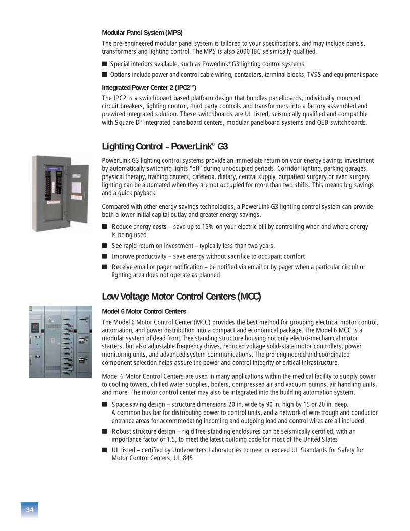
34
Modular Panel System (MPS)
The pre-engineered modular panel system is tailored to your specifications, and may include panels,transformers and lighting control. The MPS is also 2000 IBC seismically qualified.
� Special interiors available, such as Powerlink® G3 lighting control systems
� Options include power and control cable wiring, contactors, terminal blocks, TVSS and equipment space
Integrated Power Center 2 (IPC2TM)
The IPC2 is a switchboard based platform design that bundles panelboards, individually mounted circuit breakers, lighting control, third party controls and transformers into a factory assembled andprewired integrated solution. These switchboards are UL listed, seismically qualified and compatible with Square D® integrated panelboard centers, modular panelboard systems and QED switchboards.
Lighting Control – PowerLink® G3PowerLink G3 lighting control systems provide an immediate return on your energy savings investmentby automatically switching lights “off” during unoccupied periods. Corridor lighting, parking garages,physical therapy, training centers, cafeteria, dietary, central supply, outpatient surgery or even surgerylighting can be automated when they are not occupied for more than two shifts. This means big savingsand a quick payback.
Compared with other energy savings technologies, a PowerLink G3 lighting control system can provideboth a lower initial capital outlay and greater energy savings.
� Reduce energy costs – save up to 15% on your electric bill by controlling when and where energy is being used
� See rapid return on investment – typically less than two years.
� Improve productivity – save energy without sacrifice to occupant comfort
� Receive email or pager notification – be notified via email or by pager when a particular circuit orlighting area does not operate as planned
Low Voltage Motor Control Centers (MCC) Model 6 Motor Control Centers
The Model 6 Motor Control Center (MCC) provides the best method for grouping electrical motor control,automation, and power distribution into a compact and economical package. The Model 6 MCC is amodular system of dead front, free standing structure housing not only electro-mechanical motorstarters, but also adjustable frequency drives, reduced voltage solid-state motor controllers, powermonitoring units, and advanced system communications. The pre-engineered and coordinatedcomponent selection helps assure the power and control integrity of critical infrastructure.
Model 6 Motor Control Centers are used in many applications within the medical facility to supply powerto cooling towers, chilled water supplies, boilers, compressed air and vacuum pumps, air handling units,and more. The motor control center may also be integrated into the building automation system.
� Space saving design – structure dimensions 20 in. wide by 90 in. high by 15 or 20 in. deep. A common bus bar for distributing power to control units, and a network of wire trough and conductorentrance areas for accommodating incoming and outgoing load and control wires are all included
� Robust structure design – rigid free-standing enclosures can be seismically certified, with animportance factor of 1.5, to meet the latest building code for most of the United States
� UL listed – certified by Underwriters Laboratories to meet or exceed UL Standards for Safety forMotor Control Centers, UL 845
35
� Top mounted main horizontal bus and industry exclusive two-piece sliding non-conductive horizontalbus barrier – allows enhanced main bus access without the need to remove any panel, resulting inlower installation and maintenance cost
� Captive, four-bolt, horizontal slice bars – reduces installation and maintenance time with self-contained hardware allowing front access single tool joining of bus sections
� Full depth vertical wireway – features largest vertical wireway in the industry, allowing segregation ofpower, control, or communications cables
� Vertical ground bus – sections are provided with a vertical ground bus which mates with ground stabson each plug-in unit to create a positive ground connection
Intelligent Motor Control Centers (iMCC)
The integration of automation and intelligence into components has driven a revolution in motorprotection, data acquisition, and distributed control. The Model 6 intelligent motor control centers takesfull advantage of these capabilities using our Transparent Ready® architecture. This patented technologyallows instant access to system information, configuration, and diagnostics without special software viacommon web browsers.
Features� Immediate access to alarms and diagnostic information – identifies potential problems for maintenance
staff, before they become more serious, and facilitates locating problems when they do occur
� Factory installation, testing and verification of I/O points – simplifies the integration of automation andreduces field-commissioning time
� Embedded Transparent Ready Ethernet web servers – provides web-based access to motor controlcenter devices without special software via common web browsers
� Integral network communications – reduces installation cost, typically an integrated network in the motor control center will reduce the comparable installed cost by 20%
� Integrated communication cable – eliminates the control wire bundle. Mechanically protected andincluding micro-style connectors enhance network reliability in harsh industrial applications
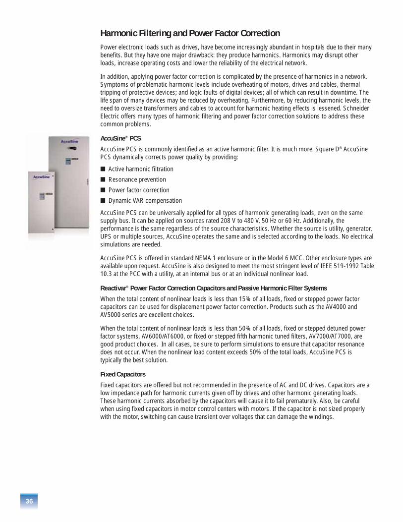
36
Harmonic Filtering and Power Factor CorrectionPower electronic loads such as drives, have become increasingly abundant in hospitals due to their manybenefits. But they have one major drawback: they produce harmonics. Harmonics may disrupt otherloads, increase operating costs and lower the reliability of the electrical network.
In addition, applying power factor correction is complicated by the presence of harmonics in a network.Symptoms of problematic harmonic levels include overheating of motors, drives and cables, thermaltripping of protective devices; and logic faults of digital devices; all of which can result in downtime. Thelife span of many devices may be reduced by overheating. Furthermore, by reducing harmonic levels, theneed to oversize transformers and cables to account for harmonic heating effects is lessened. SchneiderElectric offers many types of harmonic filtering and power factor correction solutions to address thesecommon problems.
AccuSine® PCS
AccuSine PCS is commonly identified as an active harmonic filter. It is much more. Square D® AccuSinePCS dynamically corrects power quality by providing:
� Active harmonic filtration
� Resonance prevention
� Power factor correction
� Dynamic VAR compensation
AccuSine PCS can be universally applied for all types of harmonic generating loads, even on the samesupply bus. It can be applied on sources rated 208 V to 480 V, 50 Hz or 60 Hz. Additionally, theperformance is the same regardless of the source characteristics. Whether the source is utility, generator,UPS or multiple sources, AccuSine operates the same and is selected according to the loads. No electricalsimulations are needed.
AccuSine PCS is offered in standard NEMA 1 enclosure or in the Model 6 MCC. Other enclosure types areavailable upon request. AccuSine is also designed to meet the most stringent level of IEEE 519-1992 Table10.3 at the PCC with a utility, at an internal bus or at an individual nonlinear load.
Reactivar® Power Factor Correction Capacitors and Passive Harmonic Filter Systems
When the total content of nonlinear loads is less than 15% of all loads, fixed or stepped power factorcapacitors can be used for displacement power factor correction. Products such as the AV4000 andAV5000 series are excellent choices.
When the total content of nonlinear loads is less than 50% of all loads, fixed or stepped detuned powerfactor systems, AV6000/AT6000, or fixed or stepped fifth harmonic tuned filters, AV7000/AT7000, aregood product choices. In all cases, be sure to perform simulations to ensure that capacitor resonancedoes not occur. When the nonlinear load content exceeds 50% of the total loads, AccuSine PCS istypically the best solution.
Fixed Capacitors
Fixed capacitors are offered but not recommended in the presence of AC and DC drives. Capacitors are alow impedance path for harmonic currents given off by drives and other harmonic generating loads.These harmonic currents absorbed by the capacitors will cause it to fail prematurely. Also, be carefulwhen using fixed capacitors in motor control centers with motors. If the capacitor is not sized properlywith the motor, switching can cause transient over voltages that can damage the windings.
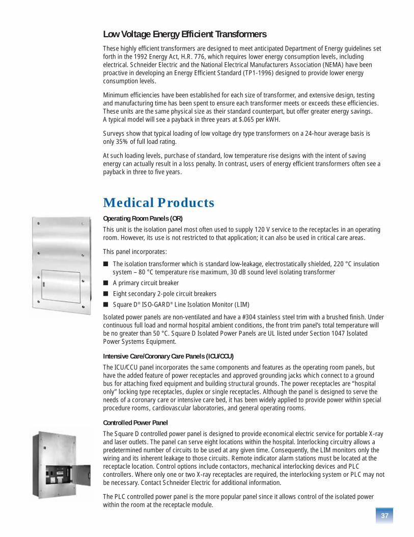
37
Low Voltage Energy Efficient Transformers These highly efficient transformers are designed to meet anticipated Department of Energy guidelines set forth in the 1992 Energy Act, H.R. 776, which requires lower energy consumption levels, includingelectrical. Schneider Electric and the National Electrical Manufacturers Association (NEMA) have beenproactive in developing an Energy Efficient Standard (TP1-1996) designed to provide lower energyconsumption levels.
Minimum efficiencies have been established for each size of transformer, and extensive design, testingand manufacturing time has been spent to ensure each transformer meets or exceeds these efficiencies.These units are the same physical size as their standard counterpart, but offer greater energy savings. A typical model will see a payback in three years at $.065 per kWH.
Surveys show that typical loading of low voltage dry type transformers on a 24-hour average basis is only 35% of full load rating.
At such loading levels, purchase of standard, low temperature rise designs with the intent of savingenergy can actually result in a loss penalty. In contrast, users of energy efficient transformers often see apayback in three to five years.
Medical ProductsOperating Room Panels (OR)
This unit is the isolation panel most often used to supply 120 V service to the receptacles in an operatingroom. However, its use is not restricted to that application; it can also be used in critical care areas.
This panel incorporates:
� The isolation transformer which is standard low-leakage, electrostatically shielded, 220 °C insulationsystem – 80 °C temperature rise maximum, 30 dB sound level isolating transformer
� A primary circuit breaker
� Eight secondary 2-pole circuit breakers
� Square D® ISO-GARD® Line Isolation Monitor (LIM)
Isolated power panels are non-ventilated and have a #304 stainless steel trim with a brushed finish. Undercontinuous full load and normal hospital ambient conditions, the front trim panel’s total temperature willbe no greater than 50 °C. Square D Isolated Power Panels are UL listed under Section 1047 IsolatedPower Systems Equipment.
Intensive Care/Coronary Care Panels (ICU/CCU)
The ICU/CCU panel incorporates the same components and features as the operating room panels, buthave the added feature of power receptacles and approved grounding jacks which connect to a groundbus for attaching fixed equipment and building structural grounds. The power receptacles are “hospitalonly” locking type receptacles, duplex or single receptacles. Although the panel is designed to serve theneeds of a coronary care or intensive care bed, it has been widely applied to provide power within specialprocedure rooms, cardiovascular laboratories, and general operating rooms.
Controlled Power Panel
The Square D controlled power panel is designed to provide economical electric service for portable X-rayand laser outlets. The panel can serve eight locations within the hospital. Interlocking circuitry allows apredetermined number of circuits to be used at any given time. Consequently, the LIM monitors only thewiring and its inherent leakage to those circuits. Remote indicator alarm stations must be located at thereceptacle location. Control options include contactors, mechanical interlocking devices and PLCcontrollers. Where only one or two X-ray receptacles are required, the interlocking system or PLC may notbe necessary. Contact Schneider Electric for additional information.
The PLC controlled power panel is the more popular panel since it allows control of the isolated powerwithin the room at the receptacle module.
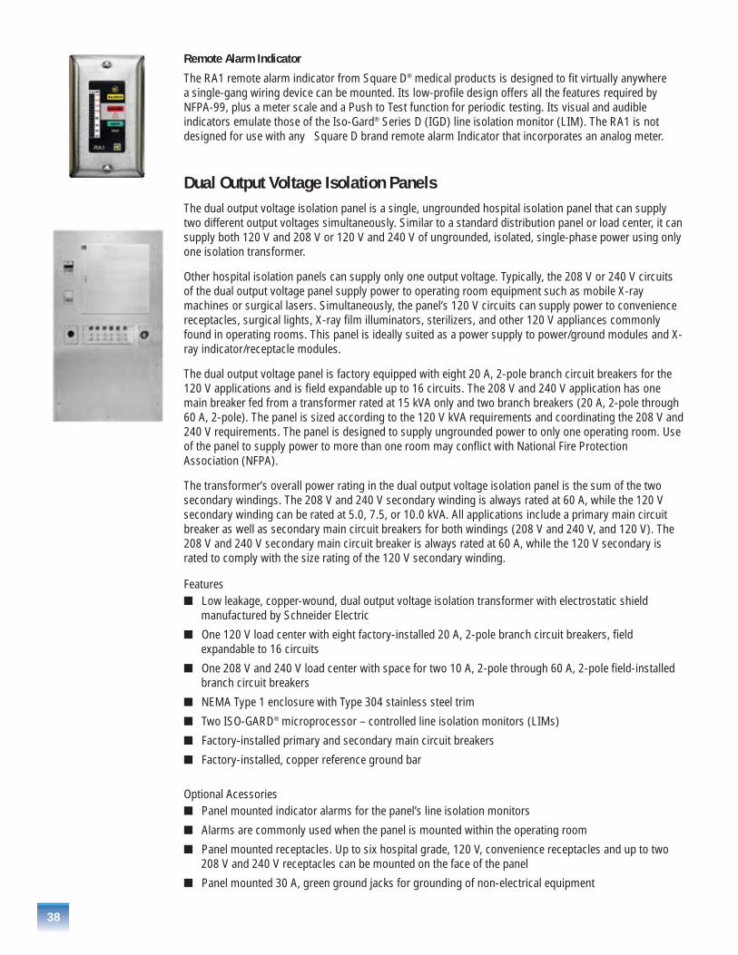
38
Remote Alarm Indicator
The RA1 remote alarm indicator from Square D® medical products is designed to fit virtually anywhere a single-gang wiring device can be mounted. Its low-profile design offers all the features required byNFPA-99, plus a meter scale and a Push to Test function for periodic testing. Its visual and audibleindicators emulate those of the Iso-Gard® Series D (IGD) line isolation monitor (LIM). The RA1 is notdesigned for use with any Square D brand remote alarm Indicator that incorporates an analog meter.
Dual Output Voltage Isolation PanelsThe dual output voltage isolation panel is a single, ungrounded hospital isolation panel that can supply two different output voltages simultaneously. Similar to a standard distribution panel or load center, it can supply both 120 V and 208 V or 120 V and 240 V of ungrounded, isolated, single-phase power using only one isolation transformer.
Other hospital isolation panels can supply only one output voltage. Typically, the 208 V or 240 V circuitsof the dual output voltage panel supply power to operating room equipment such as mobile X-raymachines or surgical lasers. Simultaneously, the panel’s 120 V circuits can supply power to conveniencereceptacles, surgical lights, X-ray film illuminators, sterilizers, and other 120 V appliances commonlyfound in operating rooms. This panel is ideally suited as a power supply to power/ground modules and X-ray indicator/receptacle modules.
The dual output voltage panel is factory equipped with eight 20 A, 2-pole branch circuit breakers for the120 V applications and is field expandable up to 16 circuits. The 208 V and 240 V application has onemain breaker fed from a transformer rated at 15 kVA only and two branch breakers (20 A, 2-pole through60 A, 2-pole). The panel is sized according to the 120 V kVA requirements and coordinating the 208 V and240 V requirements. The panel is designed to supply ungrounded power to only one operating room. Useof the panel to supply power to more than one room may conflict with National Fire ProtectionAssociation (NFPA).
The transformer’s overall power rating in the dual output voltage isolation panel is the sum of the twosecondary windings. The 208 V and 240 V secondary winding is always rated at 60 A, while the 120 Vsecondary winding can be rated at 5.0, 7.5, or 10.0 kVA. All applications include a primary main circuitbreaker as well as secondary main circuit breakers for both windings (208 V and 240 V, and 120 V). The208 V and 240 V secondary main circuit breaker is always rated at 60 A, while the 120 V secondary israted to comply with the size rating of the 120 V secondary winding.
Features� Low leakage, copper-wound, dual output voltage isolation transformer with electrostatic shield
manufactured by Schneider Electric
� One 120 V load center with eight factory-installed 20 A, 2-pole branch circuit breakers, fieldexpandable to 16 circuits
� One 208 V and 240 V load center with space for two 10 A, 2-pole through 60 A, 2-pole field-installed branch circuit breakers
� NEMA Type 1 enclosure with Type 304 stainless steel trim
� Two ISO-GARD® microprocessor – controlled line isolation monitors (LIMs)
� Factory-installed primary and secondary main circuit breakers
� Factory-installed, copper reference ground bar
Optional Acessories� Panel mounted indicator alarms for the panel’s line isolation monitors
� Alarms are commonly used when the panel is mounted within the operating room
� Panel mounted receptacles. Up to six hospital grade, 120 V, convenience receptacles and up to two208 V and 240 V receptacles can be mounted on the face of the panel
� Panel mounted 30 A, green ground jacks for grounding of non-electrical equipment
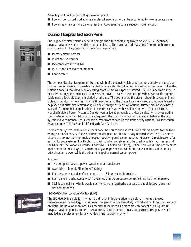
39
Advantages of dual output voltage isolation panel:� Lower labor costs-installation is simpler when one panel can be substituted for two separate panels
� Lower material cost-one panel rather than two separate panels reduces material costs
Duplex Hospital Isolation PanelThe Duplex hospital isolation panel is a single enclosure containing two complete 120 V secondaryhospital isolation systems. A divider in the unit's backbox separates the systems from top to bottom andfront to back. Each system has its own set of equipment:
� Primary circuit breaker
� Isolation transformer
� Reference ground bus bar
� ISO-GARD® line isolation monitor
� Load center
The compact Duplex design minimizes the width of the panel, which uses less horizontal wall space thantwo conventional isolation panels mounted side by side. This slim design is of particular benefit when theisolation panel is mounted in an operating room where wall space is limited. The unit is available in 5, 7fior 10 kVA ratings and includes a stainless steel cover. Because the panels provide power to life supportequipment, a lockable door is included on all units. The door covers the branch circuit breakers and lineisolation monitors to help restrict unauthorized access. The unit is totally enclosed and non-ventilated tohelp keep out dust, dirt, recirculating air and cleaning solutions. An optional surface mount back-box isavailable for remodeling applications. The entire panel assembly is listed under UL Standard 1047,Hospital Isolated Power Systems. Duplex hospital isolation panels are ideally suited for large operatingrooms where more than 14 circuits are required. The branch circuits can be divided between the twosystems to keep branch circuit leakage current from exceeding the limits set by National Fire ProtectionAssociation (NFPA) 99 Standard for Health Care Facilities.
For isolation systems with a 120 V secondary, the hazard current limit is 600 microamperes for the fixedwiring on the secondary of the isolation transformer. The limit is usually reached when 12 to 14 branchcircuits are connected. The Duplex hospital isolation panel accommodates 16 branch circuit breakers foreach of its two systems. The Duplex hospital isolation panel can also be used to satisfy requirements ofthe NFPA 70, The National Electrical Code® (NEC®) Article 517.19(a), Critical Care Areas. The panel can beapplied to both critical system and normal system power. One half of the panel can be used to supplycritical system power, while the other half supplies normal system power.
Features� Two complete isolated power systems in one enclosure
� Available in either 5, 7fi or 10 kVA ratings
� Each system is capable of accepting up to 16 branch circuit breakers
� Each panel includes two ISO-GARD® Series D microprocessor-controlled line isolation monitors
� Stainless steel trim with lockable door to restrict unauthorized access to circuit breakers and line isolation monitors
ISO-GARD Line Isolation Monitor (LIM)
The ISO-GARD line isolation monitor is a distinct fifth-generation line isolation monitor. It usesmicroprocessor technology that improves the performance, versatility, and reliability of this unit over anyprevious line isolation monitors. This monitor is included as a standard component of all Square D®
hospital isolation panels. The ISO-GARD line isolation monitor can also be purchased separately andinstalled as a replacement for any outdated line isolation monitor.
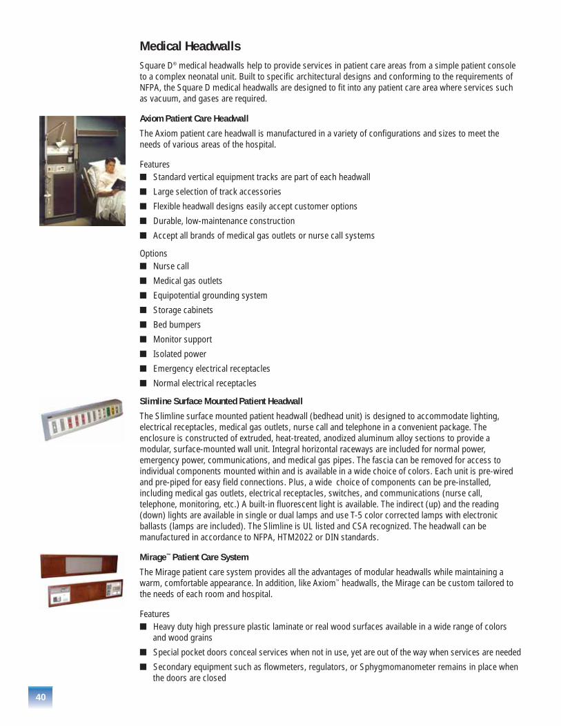
40
Medical HeadwallsSquare D® medical headwalls help to provide services in patient care areas from a simple patient consoleto a complex neonatal unit. Built to specific architectural designs and conforming to the requirements ofNFPA, the Square D medical headwalls are designed to fit into any patient care area where services suchas vacuum, and gases are required.
Axiom Patient Care Headwall
The Axiom patient care headwall is manufactured in a variety of configurations and sizes to meet theneeds of various areas of the hospital.
Features� Standard vertical equipment tracks are part of each headwall
� Large selection of track accessories
� Flexible headwall designs easily accept customer options
� Durable, low-maintenance construction
� Accept all brands of medical gas outlets or nurse call systems
Options� Nurse call
� Medical gas outlets
� Equipotential grounding system
� Storage cabinets
� Bed bumpers
� Monitor support
� Isolated power
� Emergency electrical receptacles
� Normal electrical receptacles
Slimline Surface Mounted Patient Headwall
The Slimline surface mounted patient headwall (bedhead unit) is designed to accommodate lighting,electrical receptacles, medical gas outlets, nurse call and telephone in a convenient package. Theenclosure is constructed of extruded, heat-treated, anodized aluminum alloy sections to provide amodular, surface-mounted wall unit. Integral horizontal raceways are included for normal power,emergency power, communications, and medical gas pipes. The fascia can be removed for access toindividual components mounted within and is available in a wide choice of colors. Each unit is pre-wiredand pre-piped for easy field connections. Plus, a wide choice of components can be pre-installed,including medical gas outlets, electrical receptacles, switches, and communications (nurse call,telephone, monitoring, etc.) A built-in fluorescent light is available. The indirect (up) and the reading(down) lights are available in single or dual lamps and use T-5 color corrected lamps with electronicballasts (lamps are included). The Slimline is UL listed and CSA recognized. The headwall can bemanufactured in accordance to NFPA, HTM2022 or DIN standards.
Mirage™ Patient Care System
The Mirage patient care system provides all the advantages of modular headwalls while maintaining awarm, comfortable appearance. In addition, like Axiom™ headwalls, the Mirage can be custom tailored tothe needs of each room and hospital.
Features� Heavy duty high pressure plastic laminate or real wood surfaces available in a wide range of colors
and wood grains
� Special pocket doors conceal services when not in use, yet are out of the way when services are needed
� Secondary equipment such as flowmeters, regulators, or Sphygmomanometer remains in place whenthe doors are closed

41
The Wedge™ Patient Service Column
Two fully functional headwalls in a single, freestanding unit provide flexible patient care with minimumfloor space requirements. Conceived with flexible patient access and staff productivity in mind, the Wedgepatient service columns comes complete with vertical equipment mounting rails on three sides, allowinghospital personnel to position ventilators, pumps, IVs, and baskets exactly where needed for each patient.
Beds can be placed at whatever angle allows maximum access to the patient and best use of equipment. Two beds can be parked at the column for recovery and pre-op applications.The unique angles of theWedge allow optimum access to one or two patients while using minimal floor space.
In addition, the Wedge patient services column requires only single-point connections for medical gasand electrical services. Shipped completely pre-wired and pre-piped, the Wedge patient service columnsis quickly installed and ready for use.
Features� Patented Unimount™ and Eclipse™ equipment rails for pumps, IVs, and baskets
� Communications wiring can be pre-installed
� Dual headwall design allows two patient service
� Unique angled design allows medical personnel to position the bed for access to whichever side of thepatient is necessary
� Available in over 570 colors and textures to complement any décor
� Single-point connections for medical gas and electrical connections make installation simple
� Manufactured to fit a hospital’s specific needs
Genesis™ Neonatal Patient Care Systems
Genesis neonatal patient care systems are custom manufactured to the exact requirements of thehospital. Sample units are shown in the photographs below. We can design units to meet your specificneeds, and can manufacture to the requirements of NFPA, HTM2022, or DIN requirements. All NFPA unitsare listed by Underwriter’s Laboratories. All units are pre-piped and pre-wired for easy installation.
Aurora™ Overbed Light Fixture
The Aurora overbed light fixture is a high-quality patient room light that provides three-way lighting withconvenience and elegance. It is designed for both acute care and general patient rooms. The Aurora lightprovides examination lighting by rotating the upper portion of the fixture over to aim all four lamps on thepatient. Lights in patient rooms can sometimes be damaged or even torn off the wall by IV holders,traction bars, or other equipment attached to a rising bed. To prevent damage to the light, the bed isplugged into a receptacle that is powered via a microswitch in the light. If pressure is exerted under thelight, the switch opens, the receptacle is de-energized, and the bed motor is stopped. The Aurora containsfour fluorescent, rapid-start lamps with separate circuits for the down light and the up light. The fixturecan be for either 3 or 4 ft. (914 or 1219 mm) lamps. Plus, night-lights are available for either left or righthand, and are mounted within the fixture.
The Aurora fixture is designed specifically for hospital use. Smooth, flush fitting surfaces reducehousekeeping chores. This sturdy unit has engineered resin end caps. Quality aluminum extrusions form the body and mounting plate. Upper and lower lenses are impact resistant, non-yellowing virginacrylic plastic.
Features� Designed specifically for hospital use
� Smooth, flush fitting surfaces reduce housekeeping chores
� Sturdy design has engineered resin end caps
� Features quality aluminum extrusions form the body and mounting plates
� Upper and lower lenses are impact resistant, non-yellowing virgin ac

42
Medium and Low Voltage Circuit BreakersMany circuit breakers that we manufacture are not only used in our medium and low voltage switchgear,switchboards and panelboards. We sell many breakers to OEM customers because we offer manysolutions for their needs such as the highest short circuit ratings, most reliable breakers manufacturedwith the least amount of maintenance and highest switching operations. Our circuit breakers are used byOEMs who assemble or manufacture the following equipment:
� Medium and low voltage paralleling switchgear
� Medium and Low voltage generator main breakers
Masterpact® Circuit Breakers Most OEMs in the health care market have either used or are aware of our Masterpact circuit breakers. Thesebreakers are the workhorses of the industry that are used in the most critical equipment such as generators,paralleling switchgear, switchgear and switchboards. They are very attractive because of their lowmaintenance requirements, their wide range of short circuit protection, and electrically operated accessories.
Hospital Application
� Main service low voltage switchgear – Power-Zone® 4, QED-6 and QED-2
� Low voltage paralleling switchgear – Power-Zone 4, QED-6 and QED-2
� Low voltage load bank switchgear – Power-Zone 4, QED-6 and QED-2
� Generator main output breakers
NW ANSI� Complete product offering through 200 kAIR without fuses
� 800 A to 5000 A frames available
� Rated for all AC voltage systems through 635 V
� ANSI short-time withstand ratings up to 100 kA
� Four racking positions – connected, test, disconnected, removed – with status indicator on cradle
� Simple, visual contact wear indicators
� Meets ANSI standard C37.13 and UL1066
� Full complement of field-installable devices
� Selection of four interchangeable Micrologic® trip units with PowerLogic® power metering,communications and monitoring capabilities available in advanced trip units
� Most common relay functions as defined by ANSI C37.2 and C37.90 integrated into circuit breaker
� Electrically operated optional
� 4-pole breakers available
� Mechanical and electrical operations test w/o maintenance� 800 A to 1600 A frame – 12,500 mechanical operations with 2800 electrical –
ANSI value is 1750 (9700 total)� 2000 A to 3200 A frame – 10,000 mechanical operations with 1000 electrical –
ANSI value is 250 (1100 total)� 4000 A to 5000 A frame – 5,000 mechanical operations with 1000 electrical –
ANSI value is 250 (1100 total)� Arc flash limiting breakers available
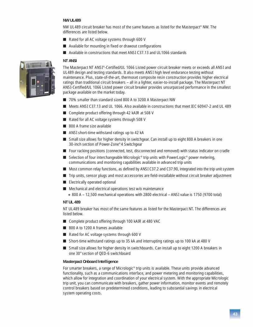
43
NW UL489
NW UL489 circuit breaker has most of the same features as listed for the Masterpact® NW. Thedifferences are listed below.
� Rated for all AC voltage systems through 600 V
� Available for mounting in fixed or drawout configurations
� Available in constructions that meet ANSI C37.13 and UL1066 standards
NT ANSI
The Masterpact NT ANSI®-Certified/UL 1066 Listed power circuit breaker meets or exceeds all ANSI and UL489 design and testing standards. It also meets ANSI high level endurance testing withoutmaintenance. Plus, state-of-the-art, thermoset composite resin construction provides higher electricalratings than traditional circuit breakers – all in a lighter, easier-to-install package. The Masterpact NTANSI-Certified/UL 1066 Listed power circuit breaker provides unsurpassed performance in the smallestpackage available on the market today.
� 70% smaller than standard sized 800 A to 3200 A Masterpact NW
� Meets ANSI C37.13 and UL 1066. Also available in constructions that meet IEC 60947-2 and UL 489
� Complete product offering through 42 kAIR at 508 V
� Rated for all AC voltage systems through 508 V
� 800 A frame size available
� ANSI short-time withstand ratings up to 42 kA
� Small size allows for higher density in switchgear. Can install up to eight 800 A breakers in one30-inch section of Power-Zone® 4 Switchgear
� Four racking positions (connected, test, disconnected and removed) with status indicator on cradle
� Selection of four interchangeable Micrologic® trip units with PowerLogic® power metering,communications and monitoring capabilities available in advanced trip units
� Most common relay functions, as defined by ANSI C37.2 and C37.90, integrated into the trip unit system
� Trip units, sensor plugs and most accessories are field-installable without circuit breaker adjustment
� Electrically operated optional
� Mechanical and electrical operations test w/o maintenance� 800 A – 12,500 mechanical operations with 2800 electrical – ANSI value is 1750 (9700 total)
NT UL 489
NT UL489 breaker has most of the same features as listed for the Masterpact NT. The differences arelisted below.
� Complete product offering through 100 kAIR at 480 VAC
� 800 A to 1200 A frames available
� Rated for AC voltage systems through 600 V
� Short-time withstand ratings up to 35 kA and interrupting ratings up to 100 kA at 480 V
� Small size allows for higher density in switchboards. Can install up to eight 1200 A breakers in one 30" section of QED-6 switchboard
Masterpact Onboard Intelligence
For smarter breakers, a range of Micrologic® trip units is available. These units provide advancedfunctionality, such as a communications interface, and power metering and monitoring capabilities, which allow for integration and coordination of your electrical system. With the appropriate Micrologictrip unit, you can communicate with breakers, gather power information, monitor events and remotelycontrol breakers based on predetermined conditions, leading to substantial savings in electrical system operating costs.
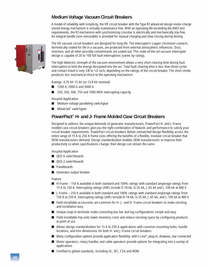
44
Medium Voltage Vacuum Circuit BreakersA model of reliability with simplicity, the VR circuit breaker with the Type RI advanced design motor-chargestored energy mechanism is virtually maintenance free. With an operating life exceeding the ANSI testrequirements, the RI mechanism with synchronizing crossbar is electrically and mechanically trip-free. An integral handle (non-removable) is provided for manual charging and slow closing during testing.
The VR vacuum circuit breakers are designed for long life. The interrupter’s copper chromium contacts,hermetically sealed for life in a vacuum, are protected from external atmospheric influences. Dust,moisture, and all other possible contaminants are sealed out. This state-of-the-art vacuum interrupterdesign is capable of 20 to 100 full fault interruptions (varies by rating).
The high dielectric strength of the vacuum environment allows a very short clearing time during faultinterruption to limit the energy dissipated into the arc. Total fault clearing time is less than three cyclesand contact travel is only 3/8 to 1/2 inch, depending on the ratings of the circuit breaker. The short strokeproduces less mechanical shock to the operating mechanism.
Ratings: 4.76 kV-15 kV (to 13.8 kV nominal)� 1200 A, 2000 A and 3000 A
� 250, 350, 500, 750 and 1000 MVA interrupting capacity
Hospital Application � Medium voltage paralleling switchgear
� Metalclad™ switchgear
PowerPact® H- and J- Frame Molded Case Circuit BreakersDesigned to address the unique demands of generator manufacturers, PowerPact H- and J-Framemolded case circuit breakers give you the right combination of features and performance to satisfy yourcircuit breaker requirements. PowerPact circuit breakers deliver unmatched design flexibility across theentire range of 15 A to 250 A frame sizes offering the benefits of a flexible, modular circuit breaker thatOEM manufacturers demand. Design standardization enables OEM manufacturers to improve theirproductivity so when specifications change, their design can remain the same.
Hospital Application� QED-6 switchboards
� QED-2 switchboards
� Panelboards
� Generator output breaker
Feature� H-Frame – 150 A available in both standard and 100% ratings with standard amperage ratings from
15 A to 150 A. Interrupting ratings (AIR) include D-18 kA, G-35 kA, J-65 kA and L-100 kA at 480 V
� J-Frame – 250 A available in both standard and 100% ratings with standard amperage ratings from 150 A to 250 A. Interrupting ratings (AIR) include D-18 kA, G-35 kA, J-65 kA, and L-100 kA at 480 V
� Field-installable accessories are common for H- J- and D- Frame circuit breakers to make stocking and installation easy
� Unique snap-in terminals make converting bus bar and lug configurations simple and easy
� Field-installable trip units lower inventory costs and reduce stocking space by configuring products at point of use
� Allows design standardization for 15 A to 250 A applications with common mounting holes, handlelocations, and trim dimensions for both H- and J-Frame circuit breakers
� Many configuration options provide application flexibility, with I-Line®, plug-in, drawout, rear connected
� Motor operators, rotary handles and cable operators provide options for integrating into a variety ofapplications
� Certified to global standards, including UL, IEC, CSA and NOM
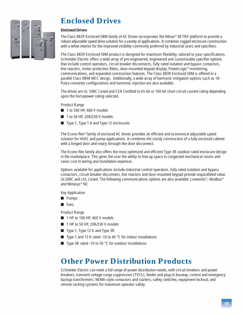
45
Enclosed DrivesEnclosed Drives
The Class 8839 Enclosed 58M family of AC Drives incorporates the Altivar® 58 TRX platform to provide arobust adjustable speed drive solution for a variety of applications. It combines rugged enclosure constructionwith a white interior for the improved visibility commonly preferred by industrial users and specifiers.
The Class 8839 Enclosed 58M product is designed for maximum flexibility, tailored to your specifications.Schneider Electric offers a wide array of pre-engineered, engineered and customizable specifier optionsthat include control operators, circuit breaker disconnects, fully rated isolation and bypass contactors,line reactors, motor protection filters, door-mounted keypad display, PowerLogic® monitoring,communications, and expanded construction features. The Class 8839 Enclosed 58M is offered in aparallel Class 8898 MCC design. Additionally, a wide array of harmonic mitigation options such as 18-Pulse converter configurations and harmonic injection are also available.
The drives are UL 508C Listed and CSA Certified to 65 kA or 100 kA short circuit current rating dependingupon the horsepower rating selected.
Product Range� 1 to 500 HP, 460 V models
� 1 to 50 HP, 208/230 V models
� Type 1, Type 1 A and Type 12 enclosures
The Econo-flex® family of enclosed AC drives provides an efficient and economical adjustable speedsolution for HVAC and pump applications. It combines the sturdy construction of a fully enclosed cabinetwith a hinged door and rotary through-the-door disconnect.
The Econo-flex family also offers the most optimized and efficient Type 3R outdoor rated enclosure designin the marketplace. This gives the user the ability to free up space in congested mechanical rooms andsaves cost in wiring and installation expenses.
Options available for applications include industrial control operators, fully rated isolation and bypasscontactors, circuit breaker disconnect, line reactors and door-mounted keypad provide unparalleled value.UL508C and cUL Listed. The following communications options are also available: Lonworks®, Modbus®
and Metasys® N2.
Key Application� Pumps
� Fans
Product Range� 1 HP to 100 HP, 460 V models
� 1 HP to 50 HP, 208/230 V models
� Type 1, Type 12 K and Type 3R
� Type 1 and 12 K rated -10 to 40 °C for indoor installations
� Type 3R rated -10 to 50 °C for outdoor installations
Other Power Distribution ProductsSchneider Electric can meet a full range of power distribution needs, with circuit breakers and powerbreakers; transient voltage surge suppression (TVSS), feeder and plug-in busway, control and emergencybackup transformers; NEMA-style contactors and starters; safety switches; equipment lockout; andremote racking systems for maximum operator safety.
46
Square D® Services Products and Engineering ServicesSquare D Services offers one source of service expertise on all major brands of electrical equipment. Our solutions are designed to enhance performance, improve reliability and extend equipment life.
Power System Assessment� Evaluates the condition of the electrical system
� Improves system reliability and availability
� Enhances electrical safety
� Provides essential documentation of system configuration, condition and maintenance
� Ensures proper operation of new or modified loads
� Prioritizes system improvements
Engineering StudiesPower Quality Studies� Analyze power system disturbances and interruptions that decrease productivity and reliability
� Reduce cost effect of poor power quality
� Troubleshooting power system problems caused from utility voltage sags, lightning or from mediumvoltage capacitors switching
Harmonic Studies� Identify excessive harmonic distortion and loading
� Properly size capacitors in the presence of harmonic generating loads
� Evaluate and identify harmonic mitigating saving opportunities
� Solve problem due to voltage notching cause by SCR firing in DC drives
� Optimize existing electrical distribution system and ensure proper operation of sensitive equipment
� IEEE 519 compliance
Short Circuit, Coordination and Arc Flash Analysis� Identifies overdutied equipment due to high fault currents caused by system design additions or utility
network changes
� Prevents nuisance tripping of protective devices and ensures coordination with downstream devices
� Checks that feeder and branch conductors are adequately protected
� Generates updated AutoCAD one line diagram model of facility
� Addresses ground fault coordination and grounding concerns
� Identifies NEC code violations
� Determines proper Personal Protective Equipment (PPE) for workers who work on energized parts per NFPA 70E or IEEE 1584
� Provides arc flash tables to determine required labels for equipment
� Determines arc flash boundaries for non-qualified personnel
Additional Studies available� Power factor correction
� Transient motor starting
� Load flow using portable metering or simulated with software
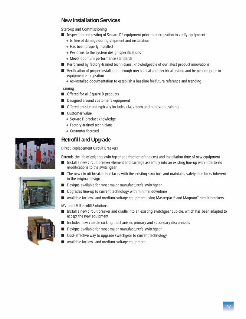
47
New Installation Services Start-up and Commissioning� Inspection and testing of Square D® equipment prior to energization to verify equipment
� Is free of damage during shipment and installation� Has been properly installed� Performs to the system design specifications� Meets optimum performance standards
� Performed by factory-trained technicians, knowledgeable of our latest product innovations
� Verification of proper installation through mechanical and electrical testing and inspection prior toequipment energization
� As-installed documentation to establish a baseline for future reference and trending
Training� Offered for all Square D products
� Designed around customer’s equipment
� Offered on-site and typically includes classroom and hands-on training
� Customer value� Square D product knowledge� Factory-trained technicians� Customer focused
Retrofill and Upgrade Direct Replacement Circuit Breakers
Extends the life of existing switchgear at a fraction of the cost and installation time of new equipment� Install a new circuit breaker element and carriage assembly into an existing line-up with little-to-no
modifications to the switchgear
� The new circuit breaker interfaces with the existing structure and maintains safety interlocks inherentin the original design
� Designs available for most major manufacturer’s switchgear
� Upgrades line-up to current technology with minimal downtime
� Available for low- and medium-voltage equipment using Masterpact® and Magnum™ circuit breakers
MV and LV Retrofill Solutions� Install a new circuit breaker and cradle into an existing switchgear cubicle, which has been adapted to
accept the new equipment
� Includes new cubicle racking mechanism, primary and secondary disconnects
� Designs available for most major manufacturer’s switchgear
� Cost-effective way to upgrade switchgear to current technology
� Available for low- and medium-voltage equipment

48
C5 Reconditioned Program
The C5 Reconditioned program for low voltage and medium voltage power circuit breakers ensures eachbreaker is Checked, Cleaned, Corrected, Calibrated and Certified through the following steps:
� Complete disassembly and inspection of the circuit breaker at the component level
� Clean and repaint/replate key components; replace old hardware
� Identify damaged or defective components for replacement (additional charge to replace)
� Relubricate moving parts and operating mechanisms
� Calibrate to manufacturer’s specification when the circuit breaker is reassembled
Maintenance and Testing Preventive Maintenance� Periodic inspection and maintenance to help extend equipment life and ensure operating efficiency
� Comprehensive mechanical and electrical testing to ensure proper functional operation, including:� Cable testing� Relay and metering calibration� Infrared testing
� Also available:� Custom service agreements� Facility-wide outage management
� Services also available for non-Square D® equipment
Workplace SafetyNFPA 70E Training Workshop� 8-hour course taught by certified instructors
� Designed to provide participants with a basic understanding of safe workplace practices
� NFPA 70E Part 2 (Arc Flash) standards are reviewed and explained
� Includes an overview of proper distribution equipment maintenance
Emergency Services and Disaster Recovery� Problem analysis
� Project management
� Single point of contact
� 1-888-SQUARED
� 24-Hour access to Schneider Electric
� Manufacturing plants

©20
06 S
chne
ider
Ele
ctric
. A
ll R
ight
s R
eser
ved.
12-06 tkOrder Number 4800SM0501
Schneider Electric - North American Operating Division1415 S. Roselle RoadPalatine, IL 60067Tel: 847-397-2600Fax: 847-925-7500