Embed Size (px)
Citation preview

MAINTENANCE MANUAL
Hose End Pressure Control Valve F594/F595 Series
Revision 3.0 May 2016
Meggitt (North Hollywood), Inc. Proprietary Information
The information contained in this document is disclosed in confidence. It is the property of Meggitt (North Hollywood), Inc. and shall not be used, disclosed to others, or reproduced in whole or in part without the express written consent of Meggitt (North Hollywood), Inc. If consent is given, this notice shall appear in any such reproduction. These commodities, technology, or software were exported from the United States in accordance with the export administration regulations. Diversion contrary to U.S. law is prohibited.
SENSITIVE BUT UNCLASSIFIED-EXPORT CONTROLLED-EAR RESTRICTED. These commodities, technology or software are exported from the United States of America in accordance with the Export Administration Regulations. ECCN EAR99. Diversion contrary to U.S. law is prohibited.
Copyright © 2016 Meggitt (North Hollywood), Inc.

Meggitt Fuelling Products Maintenance Manual (MMF594/F595)
Hose End Pressure Control Valve – F594/F595 Series
USE OR DISCLOSURE OF DATA ON THIS PAGE IS SUBJECT TO THE RESTRICTIONS ON THE TITLE PAGE OF THIS DOCUMENT
May 2016 Revision 3.0 RR
REVISION RECORD
Keep this record in the front of the manual. When new issues are received, put the revised pages in the manual. Write the issue number, date and initials on this page.
Rev. No.
PAGES AFFECTED DESCRIPTION OF CHANGE DATE
APPROVED BY
1.0 ALL INITIAL RELEASE 2001/05/21
1.1 ALL UPDATE MANUAL DATA 2006/02/01
1.2 ALL UPDATE MANUAL DATA 2007/03/01
2.0 ALL UPDATE MANUAL FORMAT/DATA 2013/01/13 A.B
3.0 ALL See DCN 2016/08/22 A.J.

Meggitt Fuelling Products Maintenance Manual (MMF594/F595)
Hose End Pressure Control Valve – F594/F595 Series
USE OR DISCLOSURE OF DATA ON THIS PAGE IS SUBJECT TO THE RESTRICTIONS ON THE TITLE PAGE OF THIS DOCUMENT
May 2016 Revision 3.0 i/ii (blank)
TABLE OF CONTENTS SUBJECT PAGE IMPORTANT SAFETY INSTRUCTIONS ........................................................................................................ A INTRODUCTION ............................................................................................................................................. 1 DESCRIPTION AND OPERATION ................................................................................................................. 3 FAULT ISOLATION ....................................................................................................................................... 11 DISASSEMBLY ............................................................................................................................................. 13 CLEANING .................................................................................................................................................... 15 INSPECTION ................................................................................................................................................ 17 ASSEMBLY ................................................................................................................................................... 19 TESTING ....................................................................................................................................................... 21 ILLUSTRATED PARTS LIST ........................................................................................................................ 23
LIST OF ILLUSTRATIONS FIGURE PAGE Figure 1. Hose End Pressure Control Valve ................................................................................................. 3 Figure 2. Valve Cross-Section ...................................................................................................................... 4 Figure 3. F594A Flow Curves ....................................................................................................................... 7 Figure 4. F595A Flow Curves ....................................................................................................................... 8 Figure 5. Valve Dimensions .......................................................................................................................... 9 Figure 6. (F595) Pin in Valve Body Detail .................................................................................................. 20 IPL Figure 1. Hose End Pressure Control Valve ....................................................................................... 24
LIST OF TABLES TABLE PAGE Table 1. Leading Particulars ........................................................................................................................ 5 Table 2. Model Variations ............................................................................................................................ 6 Table 3. Fault Isolation .............................................................................................................................. 11 Table 4. Recommended Disassembly Materials ....................................................................................... 13 Table 5. Recommended Cleaning Materials ............................................................................................. 15 Table 6. Component Checks ..................................................................................................................... 17 Table 7. Recommended Assembly Materials ............................................................................................ 19

Meggitt Fuelling Products Maintenance Manual (MMF594/F595)
Hose End Pressure Control Valve – F594/F595 Series
USE OR DISCLOSURE OF DATA ON THIS PAGE IS SUBJECT TO THE RESTRICTIONS ON THE TITLE PAGE OF THIS DOCUMENT
May 2016 Revision 3.0 A
IMPORTANT SAFETY INSTRUCTIONS
SAVE THESE INSTRUCTIONS!
This manual contains important instructions that should be followed during installation and maintenance of the Hose End Pressure Control Valve (valve). The following are general safety precautions that are not related to specific procedures and therefore do not appear elsewhere in this publication. These are recommended precautions that personnel must understand and apply during maintenance.
The valve is a mechanical device and is pressure driven. The valve can be dangerous if not correctly operated or maintained.
Safety Alert Symbols
Safety alert symbols are used in this manual to identify potential or immediate personal injury hazards. The safety alert symbol words are explained below:
- indicates an imminently hazardous situation which, if not avoided, will result in injury or serious injury.
- indicates a potentially hazardous situation which, if not avoided, could result in injury or serious injury.
- indicates a potentially hazardous situation which, if not avoided, may result in minor or moderate injury.
- used without the safety alert symbol indicates a potentially hazardous situation which, if not avoided, may result in property damage.
WEAR PROTECTIVE CLOTHING
• Wear protective clothing (gloves, apron, etc.) approved for the materials and tools being used.
USE APPROVED SAFETY EQUIPMENT
• Use only approved equipment and make sure firefighting equipment is readily available.

Meggitt Fuelling Products Maintenance Manual (MMF594/F595)
Hose End Pressure Control Valve – F594/F595 Series
USE OR DISCLOSURE OF DATA ON THIS PAGE IS SUBJECT TO THE RESTRICTIONS ON THE TITLE PAGE OF THIS DOCUMENT
May 2016 Revision 3.0 B
GIVE CLEANERS SPECIAL CARE
• When cleaners are being used, read and obey the material safety data sheet (MSDS) instructions for correct handling.
Equipment Safety Information
The following safety information briefly discusses hazards peculiar to the equipment, which are likely to be encountered during maintenance activity.
GENERAL OPERATING LOCATION PRECAUTIONS
• Use only authorized replacement parts or hardware.
• Obey Lock-Out/Tag-Out procedures when working on the valve and make sure that personnel protection equipment such as electrical grounds are installed.
• Avoid hazardous voltage situations that can result from unsafe conditions such as, but not limited, to the following:
o Incorrect grounding
o Handling electrical leads or devices with wet hands or on wet ground.
o Damaged electrical wire insulation.
o Incorrect connection of the power terminals.
o Short circuits to ground.
OPERATION AND MAINTENANCE OF FUEL SYSTEMS
• Protect all fuel lines from damage or puncture. Do not operate the valve if a fuel leak is detected.
• Do not use flammable solvents for cleaning parts.
• Before operation, make sure there are no tools, rags, or loose parts left in the area.
• Do not remove the valve from the system without first isolating it from the line pressure and venting all of the trapped internal pressure.
Meggitt Fuelling Products Maintenance Manual (MMF594/F595)
Hose End Pressure Control Valve – F594/F595 Series
USE OR DISCLOSURE OF DATA ON THIS PAGE IS SUBJECT TO THE RESTRICTIONS ON THE TITLE PAGE OF THIS DOCUMENT
May 2016 Revision 3.0 1/2 (blank)
INTRODUCTION
1. General
The information and procedures contained in this manual have been prepared to assist qualified repair personnel in off-aircraft maintenance of the Hose End Pressure Control Valve. The instructions provide information necessary to accomplish maintenance functions. The valve is manufactured by Meggitt (North Hollywood), Inc., 12838 Saticoy Street, North Hollywood, California 91605.
2. Scope
The instructions contained in this manual do not claim to cover all details or variations in equipment. They do not provide for every problem that could occur during installation, operation, or maintenance. If further information is required, contact Meggitt (North Hollywood), Inc., Product Support Department.
3. Standard Shop Practices
Use approved procedures and safety precautions to prevent damage to the equipment and injury to personnel.
4. Weights and Measurements
Weights and measurements in this manual are expressed in both English (U.S. customary) and Metric (SI) units.
5. Revision Service
This manual will be revised, as necessary, to reflect current information.


Meggitt Fuelling Products Maintenance Manual (MMF594/F595)
Hose End Pressure Control Valve – F594/F595 Series
USE OR DISCLOSURE OF DATA ON THIS PAGE IS SUBJECT TO THE RESTRICTIONS ON THE TITLE PAGE OF THIS DOCUMENT
May 2016 Revision 3.0 3
DESCRIPTION AND OPERATION
1. Description
The Hose End Pressure Control Valve (see Figure 1) provides the means of controlling higher flow rates in aircraft refueling operations. The valve inlet is connected to the end of the hose supplying the fuel, ahead of the nozzle. Many valve outlet/outlet flange/adapter combinations are available to mate with the varying nozzle and hose variations. The major functional components of the valve are the outlet adapter, the poppet and the valve body. The F595 series valve has provisions for a manual lockout assembly used for system setup and checkout. The lockout assembly can be ordered separately.
Figure 1. Hose End Pressure Control Valve

Meggitt Fuelling Products Maintenance Manual (MMF594/F595)
Hose End Pressure Control Valve – F594/F595 Series
USE OR DISCLOSURE OF DATA ON THIS PAGE IS SUBJECT TO THE RESTRICTIONS ON THE TITLE PAGE OF THIS DOCUMENT
May 2016 Revision 3.0 4
DURING PRESSURE ASSISTED DE-FUELING OPERATIONS, THE HOSE END PRESSURE CONTROL VALVE MUST NOT OPERATE. USE A (F594) HYDRAULIC OR A (F595) MECHANICAL LOCKOUT DEVICE.
2. Operation
The valve (see Figure 2) contains a large sleeve-type poppet which is normally held in its open position by a spring. When the downstream pressure increases to the control pressure of the valve, the poppet begins to close. This reduces the flow and maintains the control pressure at the nozzle. If there are sudden increases in the downstream pressure, the poppet will close rapidly, and limit the downstream surge pressure to an acceptable level.
18
18. O-RING
BODY, VALVE
SPRING, COMPRESSIONSEAL, CHANNEL
BALL BEARING
SEAL, LIPRING, RETAINING SPIROLOX®
Figure 2. Valve Cross-Section

Meggitt Fuelling Products Maintenance Manual (MMF594/F595)
Hose End Pressure Control Valve – F594/F595 Series
USE OR DISCLOSURE OF DATA ON THIS PAGE IS SUBJECT TO THE RESTRICTIONS ON THE TITLE PAGE OF THIS DOCUMENT
May 2016 Revision 3.0 5
3. Leading Particulars
For the leading particulars refer to Table 1.
Table 1. Leading Particulars
Service Fluid .................................................................................................................Automotive and Aviation Fuels
Performance: Operating Pressure ............................................................................................................... 0 to 200 psi (13,8 bar)
Rated Flow ......................................................................................................................................... 0 to 600 gpm
Pressure Drop (approximate) ........................................................... 2.8 psi at 300 US gpm (0,2 bar at 1 100 lpm)
Control Pressure (approximate) Mod A (basic valve) ........................................................................................................................ 45 psi (3,1 bar)
Mod B .............................................................................................................................................. 35 psi (2,4 bar)
(F594) Mod G (air-set) .............................................................................................. Reference air pressure +5 psi
Mod K .............................................................................................................................................. 50 psi (3,4 bar)
Mod N .............................................................................................................................................. 55 psi (3,8 bar)
Flow Characteristics .............................................................................. (F594A) See Figure 3, and (F595A) Figure 4
Temperature: Ambient ......................................................................................................................... –40 to 160°F (–54 to 71°C) Fluid .............................................................................................................................. –40 to 160°F (–54 to 71°C)
Envelope Dimensions .............................................................................................................................. See Figure 5
Weight (approximate) .................................................................................................................. 2.3 pounds (1,05 kg)
4. Model Variations
A. General
The basic F594A/F595A series valve has flanged inlets to mate with F582/F584 series swivels, and outlets to mate with F116/F117/F145 series nozzles. The flanges also mate with the older F100/F115 series nozzles and F577/F577 series swivels. Refer to Table 2 for the available valve variations. Refer to the ILLUSTRATED PARTS LIST section for additional details.

Meggitt Fuelling Products Maintenance Manual (MMF594/F595)
Hose End Pressure Control Valve – F594/F595 Series
USE OR DISCLOSURE OF DATA ON THIS PAGE IS SUBJECT TO THE RESTRICTIONS ON THE TITLE PAGE OF THIS DOCUMENT
May 2016 Revision 3.0 6
B. F595 Supersedes F594
Note: The springs used in the F595 are different in color from the springs used in the F594. Refer to the ILLUSTRATED PARTS LIST section for the color information.
The F595 series valve has superseded and replaced the F594 series valve. The F595 series valve adds provisions for a manual lockout assembly which replaces its vent plug during system setup and testing. The vent plug is installed during normal operation of the valve.
Table 2. Model Variations
MOD LETTERS
DESCRIPTION F594 F595
Baseline F594A
– Standard hose end pressure control valve, 45 psi spring
– Baseline F595A
Standard hose end pressure control valve, 45 psi spring, vent plug assembly; lockout assembly (not included)
B Changes spring to 35 psi version
C Adds 2.5-inch internal ANPT inlet coupling
D Adds 2.5-inch internal BSPPL inlet coupling
E Adds 2.5-inch external APT outlet coupling
F Adds 2.5-inch external BSPPL outlet coupling
G – Air-set pressure control
J Adds 2-inch external ANPT outlet coupling
K Changes spring to 50 psi version
L – Adds adapter for military D-1 nozzle
M – Adds outlet flange for J. C. Carter 60427 nozzle (cannot be used with Mods C, D, E, F, J or L)
N – Changes spring to 55 psi version and substitutes yellow-green anodized valve body
– N Changes spring to 55
P Adds military standard MS33786-40 inlet and outlet flange adapters
Z Basic Manufacturing Sub-assembly

Meggitt Fuelling Products Maintenance Manual (MMF594/F595)
Hose End Pressure Control Valve – F594/F595 Series
USE OR DISCLOSURE OF DATA ON THIS PAGE IS SUBJECT TO THE RESTRICTIONS ON THE TITLE PAGE OF THIS DOCUMENT
May 2016 Revision 3.0 7
Figure 3. F594A Flow Curves

Meggitt Fuelling Products Maintenance Manual (MMF594/F595)
Hose End Pressure Control Valve – F594/F595 Series
USE OR DISCLOSURE OF DATA ON THIS PAGE IS SUBJECT TO THE RESTRICTIONS ON THE TITLE PAGE OF THIS DOCUMENT
May 2016 Revision 3.0 8
Figure 4. F595A Flow Curves

Meggitt Fuelling Products Maintenance Manual (MMF594/F595)
Hose End Pressure Control Valve – F594/F595 Series
USE OR DISCLOSURE OF DATA ON THIS PAGE IS SUBJECT TO THE RESTRICTIONS ON THE TITLE PAGE OF THIS DOCUMENT
May 2016 Revision 3.0 9/10 (blank)
F594 SERIES
0.31 (7.9)(MOD M) 0.16 (4.1)
0.25 (6.3)(MOD M) 0.15 (3.8)
(MOD M) 4.37 (110.1)PORT PER AND1005-4(7/16-20UNF-3B THREAD)
INLET FLANGE –1/4–28UNF-2B X 0.35 DEEP,6 PLACES ON 3.87 DIA BC(MOD M) 3.624 DIA BC
OUTLET FLANGE –0.281 DIA THRU,
6 PLACES ON 3.87 DIA BC(MOD M) 3.624 DIA BC
4.52 (114.8)
NOTE: DIMENSIONS ARE SHOWN IN INCHES AND (MM)
F595 SERIES
OUTLET FLANGE6 X Ø 0.282 ±0.005
(7.16 ±0.13)
OUTLET
WARNING TAGATTENTION:
INLET
VENT PLUGASSY
SHOWN WITHOUT SCREWS AND WASHERS FOR CLARITY
4.520 ±0.030(114.81 ±0.76)
INLET FLANGE6 X Ø 0.250-28 UNF-2B
0.350 MIN FULL THREAD
3.870(97.30)Ø BC
3.870(97.30)Ø BC
Figure 5. Valve Dimensions


Meggitt Fuelling Products Maintenance Manual (MMF594/F595)
Hose End Pressure Control Valve – F594/F595 Series
USE OR DISCLOSURE OF DATA ON THIS PAGE IS SUBJECT TO THE RESTRICTIONS ON THE TITLE PAGE OF THIS DOCUMENT
May 2016 Revision 3.0 11/12 (blank)
FAULT ISOLATION
1. General
Refer to Table 3 for fault isolation information. Locate component’s suspected fault, possible cause, and take corrective action.
Table 3. Fault Isolation
FAULT POSSIBLE CAUSE CORRECTIVE ACTION
External leakage from the vent port Damaged O-ring (IPL Figure 1, 11) or seal (10)
Check condition and replace O-ring and seal as necessary.
Scratches on the smaller diameter of poppet (4, 5)
Check condition and replace the poppet as necessary.
Lockup pressure is excessive Damaged O-ring (11) or seal (10) Check condition and replace O-ring and seal as necessary.
Damage to O-ring groove on poppet (4, 5)
Check condition and replace the poppet as necessary.
Control pressure is erratic Sticking or binding of poppet (4, 5) Check condition and replace the poppet, O-ring and seal as necessary.

Meggitt Fuelling Products Maintenance Manual (MMF594/F595)
Hose End Pressure Control Valve – F594/F595 Series
USE OR DISCLOSURE OF DATA ON THIS PAGE IS SUBJECT TO THE RESTRICTIONS ON THE TITLE PAGE OF THIS DOCUMENT
May 2016 Revision 3.0 13
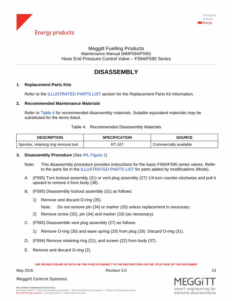
DISASSEMBLY
1. Replacement Parts Kits
Refer to the ILLUSTRATED PARTS LIST section for the Replacement Parts Kit information.
2. Recommended Maintenance Materials
Refer to Table 4 for recommended disassembly materials. Suitable equivalent materials may be substituted for the items listed.
Table 4. Recommended Disassembly Materials
DESCRIPTION SPECIFICATION SOURCE
Spirolox, retaining ring removal tool RT-107 Commercially available
3. Disassembly Procedure (See IPL Figure 1)
Note: This disassembly procedure provides instructions for the basic F594/F595 series valves. Refer to the parts list in the ILLUSTRATED PARTS LIST for parts added by modifications (Mods).
A. (F595) Turn lockout assembly (31) or vent plug assembly (27) 1/4-turn counter-clockwise and pull it upward to remove it from body (38).
B. (F595) Disassembly lockout assembly (31) as follows:
1) Remove and discard O-ring (35).
Note: Do not remove pin (34) or marker (33) unless replacement is necessary.
2) Remove screw (32), pin (34) and marker (33) (as necessary).
C. (F595) Disassemble vent plug assembly (27) as follows:
1) Remove O-ring (30) and wave spring (29) from plug (28). Discard O-ring (31).
D. (F594) Remove retaining ring (21), and screen (22) from body (37).
E. Remove and discard O-ring (2).

Meggitt Fuelling Products Maintenance Manual (MMF594/F595)
Hose End Pressure Control Valve – F594/F595 Series
USE OR DISCLOSURE OF DATA ON THIS PAGE IS SUBJECT TO THE RESTRICTIONS ON THE TITLE PAGE OF THIS DOCUMENT
May 2016 Revision 3.0 14
F. (F594) Remove retaining ring (3), poppet (4) and spring (20) from body (37).
(F595) Use retaining ring removal tool (p/n RT-107) to remove retaining ring (3), poppet assembly (4A) and spring (20) from body (38).
G. (F595) Disassemble poppet assembly (4A) as follows:
1) Remove screw (9), washer (8), and piston (7) from poppet (5). Remove and discard packing (6).
H. Remove and discard lip seal (10) and O-ring (11) from body (37, 38).
I. Remove screws (12) and retainer (13) from body (37, 38). Remove and discard O-ring (17) from the shoulder of retainer (13).
J. Remove and discard O-ring (18) and seal (19) from body (37, 38).
K. Remove O-ring (14), ball bearing (15) and spring (16) from body (37, 38). Discard O-ring (14).
L. Remove screw (23) and washers (24 and 25) from body (37, 38).
Note: (F595) Do not remove pin (26) from body (38) unless replacement is necessary.

Meggitt Fuelling Products Maintenance Manual (MMF594/F595)
Hose End Pressure Control Valve – F594/F595 Series
USE OR DISCLOSURE OF DATA ON THIS PAGE IS SUBJECT TO THE RESTRICTIONS ON THE TITLE PAGE OF THIS DOCUMENT
May 2016 Revision 3.0 15/16 (blank)
CLEANING
1. Cleaning Materials
Refer to Table 5 for recommended cleaning materials. Suitable equivalent cleaning materials may be substituted for the items listed.
Table 5. Recommended Cleaning Materials
DESCRIPTION SPECIFICATION SOURCE Bags, Plastic - Commercially available Brush, Bristle, Stiff, Non-metallic - Commercially available
Pick, Teflon® - Commercially available
Solvent, Dry Cleaning P-D-680, Type 2 Commercially available
Tissues, Lint-Free - Commercially available
DRY CLEANING SOLVENT AND ISOPROPYL ALCOHOL ARE HARZARDOUS MATERIALS. BEFORE USE, READ AND OBEY THE MATERIAL SAFETY DATA SHEET (MSDS) INSTRUCTIONS FOR CORRECT HANDLING. FAILURE TO OBEY THIS WARNING MAY RESULT IN PERSONAL INJURY, LONG TERM HEALTH HAZARDS OR DEATH.
2. Cleaning Procedures
A. Clean all metal parts by washing thoroughly in dry cleaning solvent. Remove stubborn deposits by scrubbing with a nonmetallic stiff bristle brush. Use a Teflon® pick to remove any blockage from ports, grooves, and passages.
Note: All of the parts must be free of corrosion, dirt, grease, oil, or any other foreign matter.
WEAR EYE PROTECTION WHEN DRYING PARTS WITH COMPRESSED AIR. DO NOT DIRECT AIRSTREAM AT PERSONNEL OR LIGHT METAL PARTS.
B. Dry parts with clean lint-free tissues or clean, dry compressed air.
C. Package clean parts in plastic bags.


Meggitt Fuelling Products Maintenance Manual (MMF594/F595)
Hose End Pressure Control Valve – F594/F595 Series
USE OR DISCLOSURE OF DATA ON THIS PAGE IS SUBJECT TO THE RESTRICTIONS ON THE TITLE PAGE OF THIS DOCUMENT
May 2016 Revision 3.0 17
INSPECTION
1. General
Under strong light and magnification, look at all parts in accordance with the general criteria specified in paragraph 2.
Repair minor damage in accordance with instructions presented in this section. If damage is major or beyond simple repair, replace the part.
2. Component Checks (Refer to Table 6)
Table 6. Component Checks
DESCRIPTION (IPL Figure 1 Item Number) INSPECTION CRITERIA
General Look at the parts for; nicks, cracks, cuts, burrs, corrosion, breaks, scoring, dents, thread damage, serration damage, or other damage.
Make sure the ports, passages, recesses, and grooves are clean and are not blocked.
Make sure all sealing and seating surfaces are free from damage or corrosion.
Poppet (4, 5) Sealing Outside Diameters – Check for light scoring. Can be cleaned and polished with 600-grit emery cloth.
Replace the poppet if there are any nicks in the knife-edge sealing surface. (Nicks in the knife-edge sealing surface will result in downstream leakage.)
Compression Springs (16 and 20) Replace if there is any deformation.
Seals (10 and 19) Replace if there is embedded contamination or mechanical damage.
O-rings (2, 11, 14, 18, 30 and 35) Replace if there are cuts, swelling, visible wear, deformation or other damage.
Retainer (13) Packing Shoulder – Check for corrosion and contamination. Can be cleaned and polished with 600-grit emery cloth.
Ball Bearing (15) Replace if there is any corrosion, scratching or pitting.
Marker (33) and Warning Tag (36) Make sure the markings and nomenclature can be read.

Meggitt Fuelling Products Maintenance Manual (MMF594/F595)
Hose End Pressure Control Valve – F594/F595 Series
USE OR DISCLOSURE OF DATA ON THIS PAGE IS SUBJECT TO THE RESTRICTIONS ON THE TITLE PAGE OF THIS DOCUMENT
May 2016 Revision 3.0 18
Table 6. Component Checks – (continued)
DESCRIPTION (IPL Figure 1 Item Number)
INSPECTION CRITERIA
Body (37, 38) Packing/Seal Grooves – Check for corrosion and contamination. Can be cleaned and polished with 600-grit emery cloth.
(F595) Vent Plug Port – Make sure pin (26) is secure.
(F595) Vent Plug Assy (27) Replace if the 1/4-turn fastener does not latch securely. Replace plug (28) if damage is found. Remove any burrs where the O-ring (30) grooves are on plug (28).
(F595) Lockout Assy (31) Replace if the 1/4-turn fastener does not latch securely. Replace pin (34) if damage is found. Remove any burrs where the O-ring (35) grooves are on pin (34).

Meggitt Fuelling Products Maintenance Manual (MMF594/F595)
Hose End Pressure Control Valve – F594/F595 Series
USE OR DISCLOSURE OF DATA ON THIS PAGE IS SUBJECT TO THE RESTRICTIONS ON THE TITLE PAGE OF THIS DOCUMENT
May 2016 Revision 3.0 19
ASSEMBLY
1. Replacement Parts Kits
Refer to the ILLUSTRATED PARTS LIST section for the Replacement Parts Kit information.
2. Recommended Maintenance Materials
Refer to Table 7 for recommended assembly materials. Suitable equivalent materials may be substituted for the items listed.
Table 7. Recommended Assembly Materials
DESCRIPTION SPECIFICATION SOURCE
Petroleum Jelly – Commercially available
3. Assembly Procedure (See IPL Figure 1)
A. (F594) Put screen (22) in body (37) and secure with retaining ring (21).
Note: Make sure retaining ring (21) is fully seated in its groove.
(F595) If removed, press a new pin (26) into the pin bore of the body (38), to the dimension shown in Figure 6.
B. Apply petroleum jelly to new O-ring (14) and put spring (16), ball bearing (15), and O-ring (14) in body (37, 38).
C. Apply petroleum jelly to new O-ring (18) and new seal (19); then put O-ring (18) on seal (19) and install in body (37, 38).
D. Apply petroleum jelly to new O-ring (17) and put it on the shoulder of retainer (13). Put retainer (13) along with O-ring (17) into body (37, 38); install screws (12) and torque 9 to 11 lb-in. (1 to 1,2 Nm).
E. Apply petroleum jelly to new O-ring (11) and new seal (10); and install in body (37, 38).
F. (F594) Put spring (20), poppet (4) and retaining ring (3) in body (37).

Meggitt Fuelling Products Maintenance Manual (MMF594/F595)
Hose End Pressure Control Valve – F594/F595 Series
USE OR DISCLOSURE OF DATA ON THIS PAGE IS SUBJECT TO THE RESTRICTIONS ON THE TITLE PAGE OF THIS DOCUMENT
May 2016 Revision 3.0 20
G. (F595) Assemble Poppet Assembly (4A) as follows:
1) Apply petroleum jelly to new packing (6) and put on poppet (5).
2) Put piston (7) on poppet (5) and install washer (8) and screw (9). Torque screw (9) 9 to 11 lb-in. (1 to 1,2 Nm).
H. (F595) Put spring (20), poppet assembly (4A) and retaining ring (3) in body (38).
(27)
(37, 38)
PIN (26)
VENT PLUG ASSY (27)
VALVE BODY (37, 38)
NOTE: DIMENSIONS ARE SHOWN ININCHES AND (MM)
0.165 ±0.003(4.191 ±0.076)
Figure 6. (F595) Pin in Valve Body Detail
I. (F595) Assemble Vent Plug Assembly (27) as follows:
1) Apply petroleum jelly on new O-ring (30) and put wave spring (29) and O-ring (30) on vent plug (38).
J. (F595) Assemble Lockout Assembly (31) as follows:
1) Apply petroleum jelly on new O-ring (35) and put O-ring (35) on the O-ring grooves on lockout assembly (31).
K. (F595) Put vent plug assembly (27) in body (38).
L. Package and keep; new O-ring (2), screws (23), washers (24 and 25); and (F595) lockout assembly (31) separately.
Meggitt Fuelling Products Maintenance Manual (MMF594/F595)
Hose End Pressure Control Valve – F594/F595 Series
USE OR DISCLOSURE OF DATA ON THIS PAGE IS SUBJECT TO THE RESTRICTIONS ON THE TITLE PAGE OF THIS DOCUMENT
May 2016 Revision 3.0 21
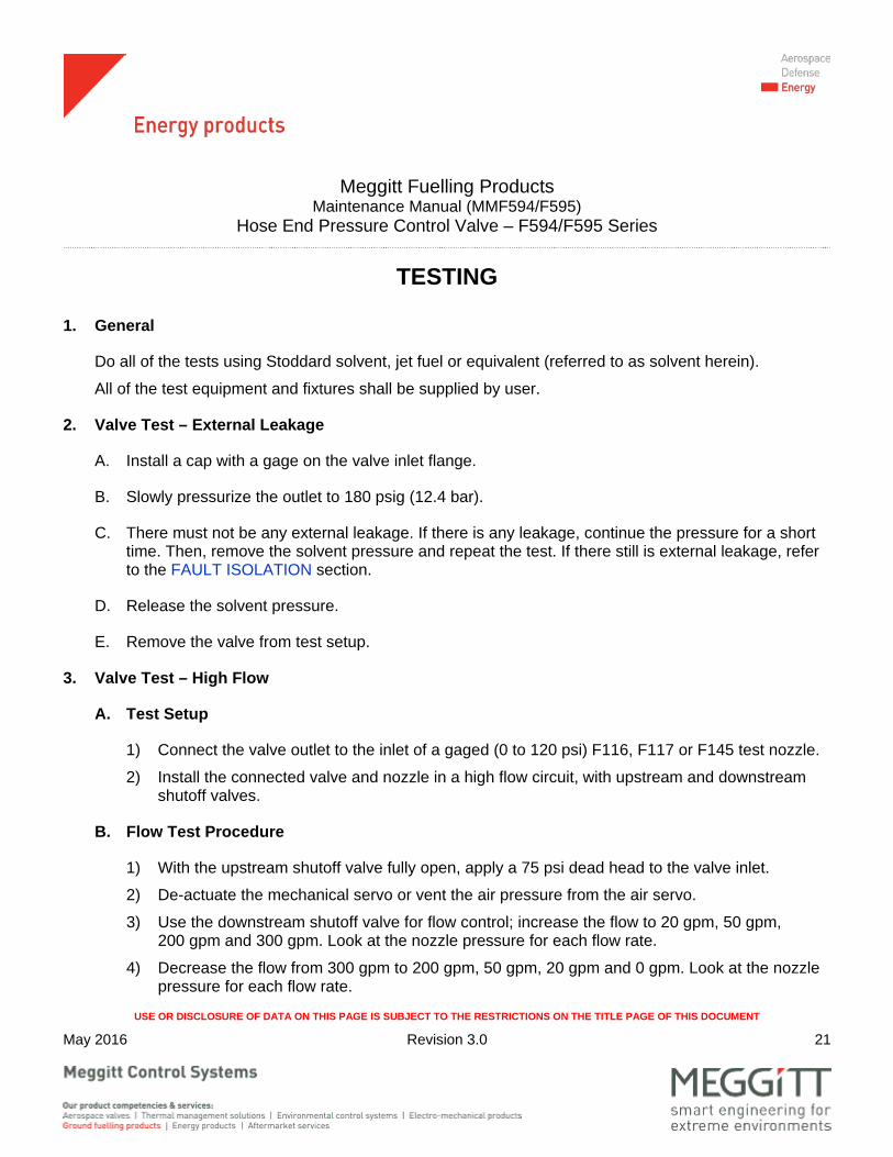
TESTING
1. General
Do all of the tests using Stoddard solvent, jet fuel or equivalent (referred to as solvent herein).
All of the test equipment and fixtures shall be supplied by user.
2. Valve Test – External Leakage
A. Install a cap with a gage on the valve inlet flange.
B. Slowly pressurize the outlet to 180 psig (12.4 bar).
C. There must not be any external leakage. If there is any leakage, continue the pressure for a short time. Then, remove the solvent pressure and repeat the test. If there still is external leakage, refer to the FAULT ISOLATION section.
D. Release the solvent pressure.
E. Remove the valve from test setup.
3. Valve Test – High Flow
A. Test Setup
1) Connect the valve outlet to the inlet of a gaged (0 to 120 psi) F116, F117 or F145 test nozzle.
2) Install the connected valve and nozzle in a high flow circuit, with upstream and downstream shutoff valves.
B. Flow Test Procedure
1) With the upstream shutoff valve fully open, apply a 75 psi dead head to the valve inlet.
2) De-actuate the mechanical servo or vent the air pressure from the air servo.
3) Use the downstream shutoff valve for flow control; increase the flow to 20 gpm, 50 gpm, 200 gpm and 300 gpm. Look at the nozzle pressure for each flow rate.
4) Decrease the flow from 300 gpm to 200 gpm, 50 gpm, 20 gpm and 0 gpm. Look at the nozzle pressure for each flow rate.

Meggitt Fuelling Products Maintenance Manual (MMF594/F595)
Hose End Pressure Control Valve – F594/F595 Series
USE OR DISCLOSURE OF DATA ON THIS PAGE IS SUBJECT TO THE RESTRICTIONS ON THE TITLE PAGE OF THIS DOCUMENT
May 2016 Revision 3.0 22
5) The nozzle pressure must be as follows:
F594A/F595A ....................................................................................... 50 psi (3.4 bar) maximum
F594B/F595B ....................................................................................... 40 psi (2.7 bar) maximum
F594K/F595K ....................................................................................... 55 psi (3.8 bar) maximum
F594N/F595N ....................................................................................... 60 psi (4.1 bar) maximum
C. Pressure Lock-Up
1) Close the upstream shutoff valve. Open the downstream shutoff valve to release the system pressure. Close the test nozzle.
2) Open the upstream shutoff valve and observe the rise of nozzle lock-up pressure for 30 seconds.
3) The nozzle lock-up pressure must be as follows:
F594A/F595A ...................................................................................... 65 psi (4.5 bar) maximum
F594B/F595B ...................................................................................... 55 psi (3.8 bar) maximum
F594K/F595K ...................................................................................... 70 psi (4.8 bar) maximum
F594N/F595N ...................................................................................... 75 psi (5.2 bar) maximum
4) Release the solvent pressure.
5) Remove the valve from test setup.

Meggitt Fuelling Products Maintenance Manual (MMF594/F595)
Hose End Pressure Control Valve – F594/F595 Series
USE OR DISCLOSURE OF DATA ON THIS PAGE IS SUBJECT TO THE RESTRICTIONS ON THE TITLE PAGE OF THIS DOCUMENT
May 2016 Revision 3.0 23
ILLUSTRATED PARTS LIST
1. General
This section lists, describes, and illustrates all detail parts required for maintenance support of the Hose End Pressure Control Valve.
2. Scope of Information
The parts list is arranged in the general order of disassembly. The listing is indentured to show the relationship between each part and its next higher assembly. Item numbers used in the parts list are keyed to the corresponding numbers of the accompanying illustration.
A. MODIFICATION CODE
The modification code (see Table 1) indicates the parts usage with respect to the end item. When the MODIFICATION CODE column is blank, the part usage is applicable to all versions unless otherwise specified in the DESCRIPTION column.
B. How to Identify a Part
When the part number is known: Refer to the parts list for the item number, description, modification codes, and quantity. Refer to the illustration to make sure of the physical appearance and location of the part.
When the part number is not known: Examine the illustrations to identify the part by physical appearance and location. Refer to the accompanying parts list to get the part number, nomenclature, modification codes, quantity, etc.
C. Abbreviations
ASSY Assembly FIG. Figure HECV Hose End Control Valve IPL Illustrated Parts List MOD Modification RF Reference

Meggitt Fuelling Products Maintenance Manual (MMF594/F595)
Hose End Pressure Control Valve – F594/F595 Series
USE OR DISCLOSURE OF DATA ON THIS PAGE IS SUBJECT TO THE RESTRICTIONS ON THE TITLE PAGE OF THIS DOCUMENT
May 2016 Revision 3.0 24
IPL Figure 1. Hose End Pressure Control Valve

Meggitt Fuelling Products Maintenance Manual (MMF594/F595)
Hose End Pressure Control Valve – F594/F595 Series
USE OR DISCLOSURE OF DATA ON THIS PAGE IS SUBJECT TO THE RESTRICTIONS ON THE TITLE PAGE OF THIS DOCUMENT
May 2016 Revision 3.0 25
FIG. ITEM PART NUMBER
DESCRIPTION 1 2 3 4 5 6 7
USED ON
CODE MOD CODE QTY
1 - 1 F594 VALVE, HOSE END, PRESSURE CONTROL ........ (SUPERSEDED BY F595)
A RF
- 1 F595 VALVE, HOSE END, PRESSURE CONTROL ........ (SUPERSEDES F594) (SUPERSEDED BY F595-1)
B RF
- 1 F595-1 VALVE, HOSE END, PRESSURE CONTROL ........ (SUPERSEDES F595)
C RF
2 2661058A042 . O-RING (NOT USED ON F594M) ......................... 1 2 2661058A151 . O-RING ................................................................. A M 1 3 RR275S . RING, RETAINING (SUPERSEDED BY F430709)
(NOT USED ON F594Z) A 1
3 F430709 . RING, RETAINING (SUPERSEDES RR275S) ..... (NOT USED ON F595Z)
B, C 1
4 2783013-101 . POPPET, MACHINED (NOT USED ON F594Z) ... A 1 4A 430017 . POPPET ASSY (NOT USED ON F595Z) .............. B, C 1 5 430437 . . POPPET .............................................................. B, C 1 6 MS29513-012 . . PACKING, PREFORMED .................................... B, C 1 7 430012 . . PISTON ................................................................ B, C 1 8 AN960C416L . . WASHER ............................................................. B, C 1 9 NAS1351N4-12 . . SCREW CAP, SOCKET HD ................................ B, C 1 10 2671765-146 . SEAL, LIP .............................................................. 1 11 2661058BD147 . O-RING .................................................................. 1 12 NK500A8-8M . SCREW (SUPERSEDED BY 100180-109) ........... A 4 12 100180-109 . SCREW (SUPERSEDES NK500A8-8M) ............... B, C 4 13 2763595-101 . RETAINER, CAST (SUPERSEDED BY F430707) A, B 1 13 F430707 . RETAINER, MACHINED .......................................
(SUPERSEDES 2763595-101) C 1
14 2661058BD007 . O-RING .................................................................. 1 15 2706786-20 . BALL BEARING (ALT MS19060-20 AND ..............
CMS19060-20) 1
15 MS19060-20 . BALL BEARING (ALT TO 2706786-20) ................. RF
- NOT ILLUSTRATED

Meggitt Fuelling Products Maintenance Manual (MMF594/F595)
Hose End Pressure Control Valve – F594/F595 Series
USE OR DISCLOSURE OF DATA ON THIS PAGE IS SUBJECT TO THE RESTRICTIONS ON THE TITLE PAGE OF THIS DOCUMENT
May 2016 Revision 3.0 26
FIG. ITEM PART NUMBER
DESCRIPTION 1 2 3 4 5 6 7
USED ON
CODE MOD
CODE QTY 1 15 CMS19060-20 . BALL BEARING (ALT TO 2706786-20) ................. RF
16 2671764 . SPRING ................................................................. 1 17 7-229N674-70 . O-RING, TETRA SEAL ..........................................
(SUPERSEDED BY F430708) A 1
17 F430708 . O-RING, TETRA SEAL ......................................... (SUPERSEDES 7-229N674-70)
B, C 1
18 S12560-126 . SEAL, CHANNEL (SUPERSEDED BY F530710) . A 1 18 F430710 . SEAL, CHANNEL (SUPERSEDES S12560-126) .. B, C 1 19 2661058BD127 . O-RING .................................................................. 1 20 2671762 . SPRING, HELICAL COMPRESSION (GREEN) ....
(NOT USED ON F594B, F594G, F594K, F594N, AND F594Z)
A 1
20 2763651-101 . SPRING, HELICAL COMPRESSION (ORANGE) . A B ` 20 2701514 . SPRING, HELICAL COMPRESSION (BLUE) ....... A K 1 20 2763651-101 . SPRING, HELICAL COMPRESSION (ORANGE) . A B 1 20 430018 . SPRING, COMPRESSION ....................................
(NOT USED ON F595B, F595K, F595N AND F595Z)
B, C 1
20 001018-101 . SPRING, HELICAL COMPRESSION (RED) ......... B, C B 1 20 2671762 . SPRING, HELICAL COMPRESSION (GREEN) .... B, C K 1 20 2775267-101 . SPRING , HELICAL COMPRESSION (WHITE) .... N 1 21 N5000-37 . RING, RETAINING ................................................ A 1 22 2671892-2 . SCREEN ................................................................ A 1 23 2706706-04-10 . SCREW, HEX SOCKET HEAD ............................
(ALT MS16998-42) (NOT USED ON F594Z) A 6
23 MS16998-42 . SCREW, HEX SOCKET HEAD (ALT TO ............. 2706706-04-10) (NOT USED ON F594Z)
A RF
23 971009-102 . SCREW, SPECIAL (ALT NAS1351C4H10) ........... (NOT USED ON F595Z)
B, C 6
23 NAS1351C4H10 . SCREW, SPECIAL (ALT TO 971009-102) ............ (NOT USED ON F595Z)
B, C RF
- NOT ILLUSTRATED
Meggitt Fuelling Products Maintenance Manual (MMF594/F595)
Hose End Pressure Control Valve – F594/F595 Series
USE OR DISCLOSURE OF DATA ON THIS PAGE IS SUBJECT TO THE RESTRICTIONS ON THE TITLE PAGE OF THIS DOCUMENT
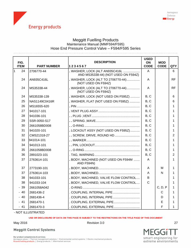
May 2016 Revision 3.0 27
FIG. ITEM PART NUMBER
DESCRIPTION 1 2 3 4 5 6 7
USED ON
CODE MOD
CODE QTY 1 24 2706770-44 . WASHER, LOCK (ALT AN935C416L ...................
AND MS35338-44) (NOT USED ON F594Z) A 6
24 AN935C416L . WASHER, LOCK (ALT TO 2706770-44) ............... (NOT USED ON F594Z)
A RF
24 MS35338-44 . WASHER, LOCK (ALT TO 2706770-44) ............... (NOT USED ON F594Z)
A RF
24 MS35338-139 . WASHER, LOCK (NOT USED ON F595Z) ........... B, C 6 25 NAS1149C0416R . WASHER, FLAT (NOT USED ON F595Z) ............ B, C 6 26 MS16555-620 . PIN ......................................................................... B, C 1 27 941017-101 . VENT PLUG ASSY ................................................ B, C 1 28 941036-101 . . PLUG ,VENT ........................................................ B, C 1 29 SSR-0050-S17 . . SPRING ,WAVE ................................................... B, C 1 30 2661058BD008 . . O-RING ................................................................ B, C 1 31 941020-101 . LOCKOUT ASSY (NOT USED ON F595Z) ........... B, C 1 32 CMS21318-27 . . SCREW, DRIVE, ROUND HD ............................. B, C 2 33 941014-101 . . MARKER .............................................................. B, C 1 34 941013-101 . . PIN, LOCKOUT .................................................... B, C 1 35 2661058BD008 . . O-RING ................................................................ B, C 1 36 2891023-101 . TAG, WARNING .................................................... B, C 2 37 2763614-101 . BODY, MACHINED (NOT USED ON F594M .......
AND F594N) A 1
37 2773190-101 . BODY, MACHINED ................................................ A M 1 37 2763614-103 . BODY, MACHINED ................................................ A N 1 38 941033-101 . BODY, MACHINED, VALVE FLOW CONTROL .... B 1 38 941033-104 . BODY, MACHINED, VALVE FLOW CONTROL .... C 1 - 39 2661058A042 . O-RING .................................................................. C, D, P 1 - 40 2681436-2 . COUPLING, INTERNAL PIPE ............................... C 1 - 40 2681436-4 . COUPLING, INTERNAL PIPE ............................... D 1 - 41 2681470-1 . COUPLING, EXTERNAL PIPE .............................. E 1 - 41 2681470-3 . COUPLING, EXTERNAL PIPE .............................. F 1
- NOT ILLUSTRATED

Meggitt Fuelling Products Maintenance Manual (MMF594/F595)
Hose End Pressure Control Valve – F594/F595 Series
USE OR DISCLOSURE OF DATA ON THIS PAGE IS SUBJECT TO THE RESTRICTIONS ON THE TITLE PAGE OF THIS DOCUMENT
May 2016 Revision 3.0 28
FIG. ITEM PART NUMBER
DESCRIPTION 1 2 3 4 5 6 7
USED ON
CODE MOD
CODE QTY 1 - 41 2681470-4 . COUPLING, EXTERNAL PIPE .............................. J 1
- 42 MS16998-42 . SCREW .................................................................. E, F, J 6 - 43 AN935C416L . WASHER, LOCK (USED ON F594L) .................... E, F, J 6 - 44 2661058A232 . PACKING (USED ON F594L) ................................ P 1 - 45 MS90728-13 . SCREW, HEX CAP (USED ON F594L) ................. P 6 - 46 MS35276-280 . SCREW .................................................................. P 6 - 47 MS35338-44 . WASHER, LOCK ................................................... P 12 - 48 MS35649-2252 . NUT (USED ON F594L) ....................................... P 6 - 49 2722490 . ADAPTER (USED ON F594L) ............................... P 1 - 50 2803005-101 . COUPLING ............................................................ P 1 - 51 AN816-4-4D . ADAPTER, STRAIGHT, PIPE TO TUBE ............... A G 1 - 52 H3C . NIPPLE, 1/4 INCH INTERCHANGE ...................... A G 1 - 53 MS29512-04 . PACKING ............................................................... A G 1
- NOT ILLUSTRATED
REPLACEMENT PARTS KITS AVAILABLE
KIT PART NUMBER DESCRIPTION ITEMS IN KIT (IPL Figure 1)
KITF595-1 Major Seal Kit 2, 10, 11, 14, 17, 18, 19
KITF595-2 (See Note1) Overhaul Kit For Piston 4A, 13
KITF595-3 Complete Overhaul Kit 2, 3, 4A, 10, 11, 13, 14, 15, 16, 17, 28, 19, and 30
KITF595-4 Major Overhaul Kit 2, 3, 10, 11, 14, 15, 16, 17, 28, 19, and 30
Note1: Order only when overhauling F595 basic configurations.