Embed Size (px)
Citation preview

Hornby P2 EM Finescale Conversion.
Before you start, it is a good idea to have some small containers or snap top poly bags to put screws and
components in for safe keeping......much better than crawling about on the floor trying to find lost bits!
We converted the tender first, because its then ready when the loco is done! There is no engine to tender
electrical connection on either the basic Railroad R3171 model as illustrated, nor on the enhanced fully lined
R3207 version. Both chassis are identical mechanically.
TENDER CONVERSION
1. Invert the tender, and hold in a suitable device. We use a foam cradle – the Peco loco service cradle being
ideal.
2. Remove the rear coupling from its housing.....this hides one of the keeper plate screws!
Coupling removed.
3. Undo the three screws holding the keeper plate – two are visible, the third being deep down the hole
exposed by removing the coupling.
Once all 3 screws are removed, the keeper plate lifts away, and the tender body is also free. Remove the body
and store safely before it drops off onto the workshop Axminster!
Location of 3rd keeper plate screw.
Keeper plate removed.
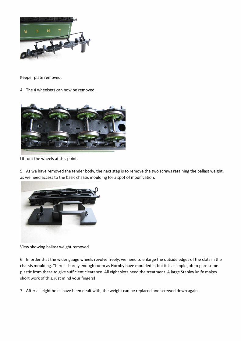
4. The 4 wheelsets can now be removed.
Lift out the wheels at this point.
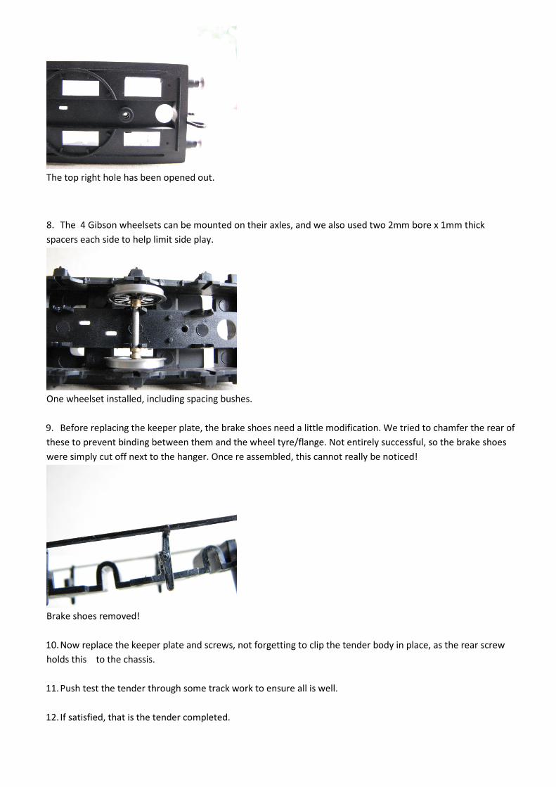
5. As we have removed the tender body, the next step is to remove the two screws retaining the ballast weight,
as we need access to the basic chassis moulding for a spot of modification.
View showing ballast weight removed.
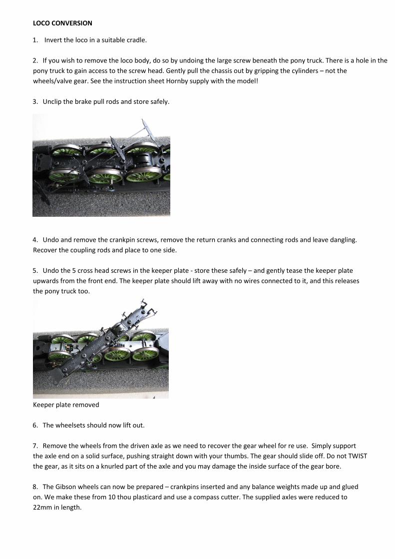
6. In order that the wider gauge wheels revolve freely, we need to enlarge the outside edges of the slots in the
chassis moulding. There is barely enough room as Hornby have moulded it, but it is a simple job to pare some
plastic from these to give sufficient clearance. All eight slots need the treatment. A large Stanley knife makes
short work of this, just mind your fingers!
7. After all eight holes have been dealt with, the weight can be replaced and screwed down again.
The top right hole has been opened out.
8. The 4 Gibson wheelsets can be mounted on their axles, and we also used two 2mm bore x 1mm thick
spacers each side to help limit side play.
One wheelset installed, including spacing bushes.
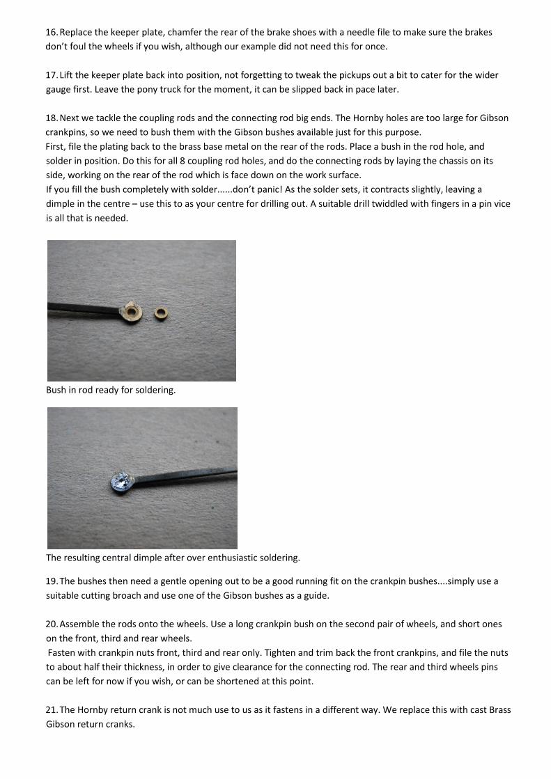
9. Before replacing the keeper plate, the brake shoes need a little modification. We tried to chamfer the rear of
these to prevent binding between them and the wheel tyre/flange. Not entirely successful, so the brake shoes
were simply cut off next to the hanger. Once re assembled, this cannot really be noticed!
Brake shoes removed!
10. Now replace the keeper plate and screws, not forgetting to clip the tender body in place, as the rear screw
holds this to the chassis.
11. Push test the tender through some track work to ensure all is well.
12. If satisfied, that is the tender completed.
LOCO CONVERSION
1. Invert the loco in a suitable cradle.
2. If you wish to remove the loco body, do so by undoing the large screw beneath the pony truck. There is a hole in the
pony truck to gain access to the screw head. Gently pull the chassis out by gripping the cylinders – not the
wheels/valve gear. See the instruction sheet Hornby supply with the model!
3. Unclip the brake pull rods and store safely.
4. Undo and remove the crankpin screws, remove the return cranks and connecting rods and leave dangling.
Recover the coupling rods and place to one side.
5. Undo the 5 cross head screws in the keeper plate - store these safely – and gently tease the keeper plate
upwards from the front end. The keeper plate should lift away with no wires connected to it, and this releases
the pony truck too.
Keeper plate removed
6. The wheelsets should now lift out.
7. Remove the wheels from the driven axle as we need to recover the gear wheel for re use. Simply support
the axle end on a solid surface, pushing straight down with your thumbs. The gear should slide off. Do not TWIST
the gear, as it sits on a knurled part of the axle and you may damage the inside surface of the gear bore.
8. The Gibson wheels can now be prepared – crankpins inserted and any balance weights made up and glued
on. We make these from 10 thou plasticard and use a compass cutter. The supplied axles were reduced to
22mm in length.

Gibson wheels fitted with balance weights.
9. Now begin to assemble the front, second and rear wheelsets. We will need some spacing washers to take up
the side play. We used 2 x 1mm plus 1 x 0.5mm thick washers each side for all axles, as the chassis varies in
width over the axle boxes to allow for side play.
10. We use a GW Models wheel press for assembly, which will also quarter the wheels as well as press them on
square.
Assembled wheels for front or rear.
11. These three wheel sets can now be placed in the chassis.
Front and second wheelsets installed.
12. The centre axle needs to be “knurled” for the gear wheel first. We place the plain axle into the chassis,
measuring the overhang each side to make sure it is central. Take a permanent marker pen, and mark the
position of the gear on the axle.

The black dot marks the spot!
13. Place the axle on a cutting mat or similar. Take a small hand file, we use a 4 inch second cut file, and using
the file on Edge, roll it with firm downward pressure over the axle where you marked the gear position. Do not
stray away from this narrow area, as bushes run on the axle very close to the gear, and knurling in these areas
won’t help good running!
Not too neat....but it works!
14. The gear can now be slid onto the axle and pressed over the “knurling”. We found that the side of the gear
was 7mm from the axle end (shorter end!) Place in the chassis and check... you may apply a touch of Loctite if
you wish, but we find that if sufficient knurling of the axle is done, there is no need for this.
Assembled axle and Hornby gear.
15. Next, assemble the driven axle in the press with spacers.
Driven axle installed.
16. Replace the keeper plate, chamfer the rear of the brake shoes with a needle file to make sure the brakes
don’t foul the wheels if you wish, although our example did not need this for once.
17. Lift the keeper plate back into position, not forgetting to tweak the pickups out a bit to cater for the wider
gauge first. Leave the pony truck for the moment, it can be slipped back in pace later.
18. Next we tackle the coupling rods and the connecting rod big ends. The Hornby holes are too large for Gibson
crankpins, so we need to bush them with the Gibson bushes available just for this purpose.
First, file the plating back to the brass base metal on the rear of the rods. Place a bush in the rod hole, and
solder in position. Do this for all 8 coupling rod holes, and do the connecting rods by laying the chassis on its
side, working on the rear of the rod which is face down on the work surface.
If you fill the bush completely with solder......don’t panic! As the solder sets, it contracts slightly, leaving a
dimple in the centre – use this to as your centre for drilling out. A suitable drill twiddled with fingers in a pin vice
is all that is needed.
Bush in rod ready for soldering.
The resulting central dimple after over enthusiastic soldering.
19. The bushes then need a gentle opening out to be a good running fit on the crankpin bushes....simply use a
suitable cutting broach and use one of the Gibson bushes as a guide.
20. Assemble the rods onto the wheels. Use a long crankpin bush on the second pair of wheels, and short ones
on the front, third and rear wheels.
Fasten with crankpin nuts front, third and rear only. Tighten and trim back the front crankpins, and file the nuts
to about half their thickness, in order to give clearance for the connecting rod. The rear and third wheels pins
can be left for now if you wish, or can be shortened at this point.
21. The Hornby return crank is not much use to us as it fastens in a different way. We replace this with cast Brass
Gibson return cranks.
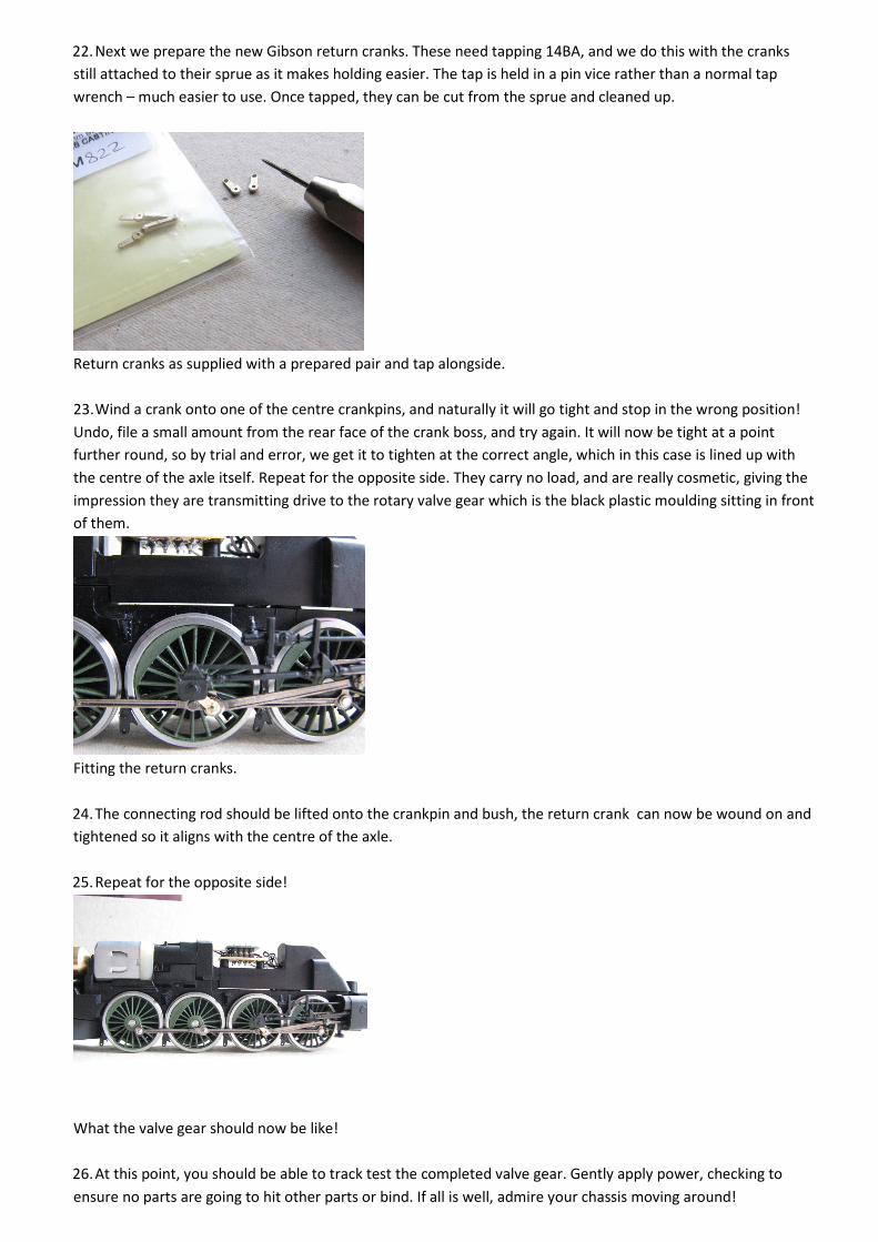
22. Next we prepare the new Gibson return cranks. These need tapping 14BA, and we do this with the cranks
still attached to their sprue as it makes holding easier. The tap is held in a pin vice rather than a normal tap
wrench – much easier to use. Once tapped, they can be cut from the sprue and cleaned up.
Return cranks as supplied with a prepared pair and tap alongside.
23. Wind a crank onto one of the centre crankpins, and naturally it will go tight and stop in the wrong position!
Undo, file a small amount from the rear face of the crank boss, and try again. It will now be tight at a point
further round, so by trial and error, we get it to tighten at the correct angle, which in this case is lined up with
the centre of the axle itself. Repeat for the opposite side. They carry no load, and are really cosmetic, giving the
impression they are transmitting drive to the rotary valve gear which is the black plastic moulding sitting in front
of them.
Fitting the return cranks.
24. The connecting rod should be lifted onto the crankpin and bush, the return crank can now be wound on and
tightened so it aligns with the centre of the axle.
25. Repeat for the opposite side!
What the valve gear should now be like!
26. At this point, you should be able to track test the completed valve gear. Gently apply power, checking to
ensure no parts are going to hit other parts or bind. If all is well, admire your chassis moving around!

THE PONY TRUCK
1. Simply twist and pull the Hornby wheel from its axle, and slide the remaining wheel and axle out the other
side.
2. Assemble one Gibson wheel onto its axle, and then slide the appropriate spacing washers on, thread through
the pony casting hole, adding the appropriate spacing washers and remaining wheel. Repeat for the second
axle. We used 2 x 1mm 2mm bore brass spacing washers each side.
Re wheeling the pony truck.
3. The completed truck can be slid under the front of the chassis keeper plate by slackening the front keeper
plate screws, and easing it gently underneath so it sits over the small lugs. Re tighten the keeper plate screws.
FINAL ASSEMBLY
Reassemble the chassis to body, and track test.
Don’t forget to lubricate it!
Pete Hill
September 2014.

List of Parts Used
1 x 4800/54 Driving wheel Conversion Pack
1 x 4838 3’2” 10 spoke
1 x 4844 3’8” 10 spoke
4 x 4849 4’1” 12 spoke
4M42 Pack of 10 Crankpins
4800 Coupling Rod Washers
4M822 Return Crank Castings
4M67/2 pack of 2mm Bore Spacing Washer Various Thicknesses
4M67/3 pack of 1/8” Bore Spacing Washer Various Thicknesses


![Kalmbach FineScale Modeler [1991-09] - Desert Storm(p22-32)](https://img.dokumen.tips/doc/110x75/5571f80549795991698c78ad/kalmbach-finescale-modeler-1991-09-desert-stormp22-32.jpg)


