Embed Size (px)
Citation preview
1
Horn-Type Piezoelectric Ultrasonic Transducer: Modelling and Applications
Tao Li1*, Jan Ma1 and Adrian F. Low2*
1School of Materials Science and Engineering, Nanyang Technological University 2National University Heart Centre; National University Health System,
Singapore
1. Introduction
The piezoelectric transducers can be categorized into sonic, ultrasonic and megasonic transducers based on the operating frequency. In each category, the design and function of the transducers vary significantly. The sonic transducers work at an audible frequency range, typically less than 20 kHz. In this frequency range, the transducers could be designed in the bending mode. Examples of the sonic transducers are the bimorph cantilever and buzzer (siren) unimorph transducer (APC International, Ltd., 2002; Yeo et al., 2008). The buzzer transducer is made of a piezoelectric disk attached to a metallic substrate. It is able to produce a sound level more than 100 dB at resonance in the frequency range of kHz (Bai et al., 2007; Miclea et al., 2008). At off-resonance conditions, the buzzer transducer can also be used as an actuator for piezoelectric diaphragm pump (Accoto et al., 2000; Woias, 2005). The ultrasonic transducers usually work at a frequency range from ~20 kHz to ~200 kHz (Abramov, 1998; Atar et al., 1999; Chen & Wu, 2002; Chu et al., 2002; Hongoh et al., 2004; Lin, 1995, 2004a; Mattiat, 1971; Medis & Henderson, 2005; Prokic, 2004; Radmanovic & Mancic, 2004; Sherrit et al., 1999a, 1999b; Tsuda et al., 1983; Wiksell et al., 2000). Transducers in this range could also be designed in the bending mode. Some examples are the tube transducer for cylindrical ultrasonic motor and disk/ring transducer for travelling wave motor (Li et al., 2007a; Uchino, 2003). But in this frequency range, a more common transducer design is the longitudinal mode. Langevin (sandwich, converter, Tonpiltz, etc.) transducer represents a typical structure (Abramov, 1998; Atar et al., 1999; Chen & Wu, 2002; Chu et al., 2002; Hongoh et al., 2004; Lin, 1995, 2004a, 2004b; Mattiat, 1971; Medis & Henderson, 2005; Prokic, 2004; Radmanovic & Mancic, 2004; Sherrit et al., 1999a, 1999b; Tsuda et al., 1983; Wiksell et al., 2000). It is sometimes connected with a horn (wave guide, booster, sonotrode, etc.) to focus or transmit energy. This type of transducer provides a wide range of applications, including welding, machining, sonochemistry, cleaning, underwater communication, ultrasonic surgery, etc. The megasonic transducers work in the frequency range of MHz. The most widely used vibration mode is the thickness mode for this range. One of the typical applications of the transducers in this category is the megasonic cleaning (Kapila et al., 2006). It provides advantages such as gentle and controllable cavitation, which will incur less damage on the cleaned parts compared with its traditional ultrasonic counterpart. Hence it is more suitable for precision cleaning.
* Corresponding Author
www.intechopen.com

Advances in Piezoelectric Transducers
4
The capability of the transducer is closely associated with the frequency, vibration mode and wavelength. As a result, different transducers will achieve different performances in a wide range of applications. In comparison, the ultrasonic transducer with longitudinal vibration mode is the only one that is able to achieve both large vibration amplitude and high power (density) simultaneously. The vibration velocity of the transducer is limited by the mechanical, thermal and electrical properties of the materials. Currently, the PZT material is only able to achieve a vibration velocity less than 1 m/s as compared to 20 m/s for the titanium material in the same ultrasonic frequency range (Li et al., 2007b; Mason & Wehr, 1970; Muhlen, 1990). Thus, by using the titanium horn, the transducer can achieve larger vibration amplitude. In addition, the transducer at the axial direction has a relative long wave length compared to the thickness mode. A large volume of the PZT material could be used to increase the power capacity of the transducer (Mason, 1964). Furthermore, the power can be focused to a small area by the horn, which further improves the power density of the transducer. Due to the superiorities of high amplitude and high power (density), the horn type transducer has been found to have many unique applications.
The shape of the horn-type transducer varies significantly depending on the applications.
Conventionally, the modelling of the transducer can be based on electrical circuit theory and
FEA theory. Typically, the electrical circuit theory is used to design the transducer while
FEA theory is used to analyze the performance of the transducer. It is convenient to use the
electrical theory to design the dimension. However, for analysis of parameters, such as
mode shape, stress distribution, power consumption, etc, the FEA theory is more
advantageous. In the present work, we proposed an improved electrical circuit theory,
called Finite Electrical Circuit Element Modelling (FECEM), which combines functions of
both design and analysis. In this method, the transducer can be represented using a
network, which are the connections of electrical circuit elements. The great advantage of the
proposed method is the high efficiency in the development of piezoelectric transducers. We
also proposed a method to estimate the mechanical quality factor Qm which is important to
estimate parameters like velocity and power consumption. Conventionally, Qm parameter
was either assumed or measured. In the present work, the FECEM was also compared with
ANSYS FEA 2D analysis. Consistent results have been found.
The ANSYS 2D fluid-structure acoustic modelling was also introduced in the present work.
In this modelling, the system response can be simulated when the transducer is loaded in
the acoustic field. This model is useful to analyze the loading effect on the transducer. It is
also essential to study the distributions and magnitude of sound pressure under different
boundary conditions.
Lastly, in this chapter two applications of the horn-type transducer are introduced. They are
thrombolysis transducer and acoustic pump. Both can be designed and analyzed using the
above mentioned FECEM and ANSYS 2D theories. The thrombolysis transducer is a horn-
type transducer connected with a long and thin transmission wire. It can be used to emulsify
the thrombus in the blood vessel. The transducer was modelled and characterized in the
present work. Efficient and effective emulsification results have been observed which
proves the design and analysis were successful. The acoustic pump is another application of
the horn-type transducer. The pump possesses a simple structure with just a transducer and
www.intechopen.com

Horn-Type Piezoelectric Ultrasonic Transducer: Modelling and Applications
5
a casing. Due to the vibration of the transducer, an acoustic field will be established inside
the casing. As a result, the liquid will be forced to flow due to the nonlinear acoustic effects,
such as streaming and cavitation. The unique features of the pump are high pressure head,
continuous flow, no body oscillation and insensitive to the tubing length. The potential
applications of the pump are sonochemistry and microfluidics.
2. General structure of the horn-type piezoelectric transducer
Fig. 1 shows the typical structure of the horn-type piezoelectric transducer. Generally, the
transducer comprises four parts, i.e., the back mass, the piezoelectric stack, the front mass
and the horn. The piezoelectric stack is clamped between the front and back mass. The horn
is coupled to the front mass through the method such as bolt. In this configuration, the
function of the piezo stack is to generate vibration, which is then amplified by the horn. The
horn together with the front and back mass also has function of impedance match to
maximize the energy transfer from the piezoelectric stack to the loadings at the tip of the
transducer (Chen et al., 2004). The horn can have various designs based on the applications,
such as conical profiled, step profiled, exponential profiled, etc (Hongoh et al., 2004; Horita,
1967; Khmelev et al., 2005; Minchenko, 1969; Muhlen, 1990). To maximize the vibration
amplitude, the horn can be designed with multiple sections. Each section has the same or
different profiles. The total length of the transducer is usually multiples of the half
wavelength.
Fig. 1. General structure of a horn-type piezoelectric transducer
3. FECEM theory
Equivalent circuit network theory is a well-accepted method in piezoelectric material study
and transducer design (Li et al., 2008, 2009, 2010; Mason,1964; Prokic, 2004; Radmanovic &
Mancic, 2004). In this method, the transducer is divided into different sections. Each section
will be represented using a two- or three-port electrical network. The networks are then
connected to represent the whole transducer. For example, in the case of Fig. 1, four
networks can be used to represent the back mass, piezo stack, front mass and the horn. The
behaviour of the transducer can then be analyzed from the obtained electrical model.
Conventionally, the method is efficient in the transducer design, such as calculating the
dimension based on the given frequency. But in the case of performance simulation or
analysis, such as calculation of stress distribution, predication of power consumption,
estimation of quality factor, etc, the application of this theory is limited. In the present work,
we proposed an improved equivalent circuit theory, called Finite Electric Circuit Element
Modelling (FECEM), which are convenient and efficient in both transducer design and
Back mass Front massPiezo stack Horn
www.intechopen.com

Advances in Piezoelectric Transducers
6
analysis. In this method, the transducer will also be divided into multiple sections. But the
section will be further divided into a number of subsections, called element. An element is
represented using an electric circuit network. The connections of the networks constitute the
electrical circuit model of the transducer. The number of elements can be flexibly selected
based on the complexity of the structure and parameters to be solved. The advantages of
this method are parameters such as mode shape, stress distribution and mechanical quality
factor can be easily solved. In the following sections, the FECEM will be introduced using
Langevin transducer as an example. For simplicity, the structure of horn is ignored. The
transducer is considered to contain front mass, piezoelectric stack and back mass. The front
and back masses are supposed to be made of the same material of aluminium. And the
piezoelectric material is PZT.
3.1 Electrical circuit element
Naturally, the Langevin transducer mentioned above can be divided into front mass section, piezoelectric stack section and back mass section. The front and back mass sections are uniform cylinders. Therefore, they can be represented using the same element as shown in Fig. 2 (Lin, 1987).
Fig. 2. Front and back mass elements
This is a two-port network, in which U1, U2 and I1, I2 are the voltages and currents at the input and output terminals. Physically, they mean the forces and velocities at the two ends of the vibrating element. Z1 and Z2 are impedances in the network. They can be expressed as
1 tan2
klZ j cS (1)
2sin
j cSZ
kl
(2)
where is density, c is sound speed, S is cross sectional area of the element, k is wave number and l is the length of the element. Based on Fig. 2, the two-port voltages can be expressed in terms of the two-port currents using the “Z” matrix (Balabanian & Bickart, 1981; Hayt & Kemmerly, 1993)
1 11 12 1
2 21 22 2
U Z Z I
U Z Z I
(3)
U1 U2
Z1 Z1
Z2
I1 I2
www.intechopen.com
Horn-Type Piezoelectric Ultrasonic Transducer: Modelling and Applications
7
where
11 1 2
12 2
21 2
22 1 2
Z Z Z
Z Z
Z Z
Z Z Z
(4)
This is actually the constitutive relations between the forces and velocities for the elements.
This relation can also be represented using the following “chain” or “ABCD” matrix
(Balabanian & Bickart, 1981; Hayt & Kemmerly, 1993)
1 2
1 2
U A B U
I C D I
(5)
where
1 2 2
1 1 2 2
2
1 2 2
2
1 /
A Z Z Z
B Z Z Z Z
C Z
D Z Z Z
(6)
The Z matrix and ABCD matrix can be converted to each other based on the following Eqs. 7
and 8. This provides much convenience for different parameter calculations (Balabanian &
Bickart, 1981; Hayt & Kemmerly, 1993).
11 21 11 22 12 21 21
21 22 211
A B Z Z Z Z Z Z Z
C D Z Z Z
(7)
11 12
21 22 1
Z Z A C AD BC C
Z Z C D C
(8)
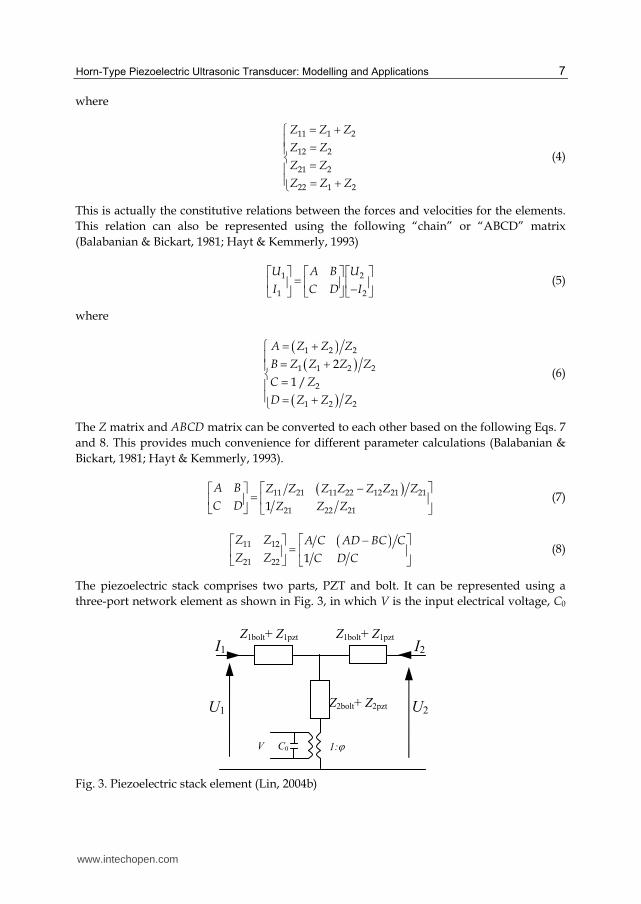
The piezoelectric stack comprises two parts, PZT and bolt. It can be represented using a
three-port network element as shown in Fig. 3, in which V is the input electrical voltage, C0
Fig. 3. Piezoelectric stack element (Lin, 2004b)
U1 U2
Z1bolt+ Z1pzt I1 I2
C0V
Z1bolt+ Z1pzt
Z2bolt+ Z2pzt
1:
www.intechopen.com
Advances in Piezoelectric Transducers
8
is the static capacitance, is the transformer ratio, Z1bolt, Z2bolt, Z1pzt and Z2pzt are the
impedances from the bolt and PZT, respectively. Z1bolt and Z2bolt can also be expressed using
Eqs. 1 and 2, respectively. The expressions for the rest parameters are shown below (Lin,
2004b; Sherrit et al., 1999a, 1999b).
1p tan2
DD
zt
k lZ j c S (9)
2
2pzt0sin
D
D
j c SZ
j Ck l
(10)
033
SC
l (11)
33
33 33D
g S
ls (12)
233
33 3333 33
1TD T
g
s
(13)
233 33 331D Es s k (14)
33
1DD
cs (15)
DD
kc
(16)
33 331 /T T (17)
33 33 33Tg d (18)
3333
33 33E T
dk
s (19)
In the above expressions, d33 is piezoelectric coefficient, 33T is dielectric constant, 33
Es is
compliance coefficient. The constitutive relation for the piezoelectric stack element will
hence be
1 11 12 1
2 21 22 2
U V Z Z I
U V Z Z I
(20)
where
www.intechopen.com

Horn-Type Piezoelectric Ultrasonic Transducer: Modelling and Applications
9
11 1 1 2 2
12 2 2
21 2 2
22 1 1 2 2
bolt pzt bolt pzt
bolt pzt
bolt pzt
bolt pzt bolt pzt
Z Z Z Z Z
Z Z Z
Z Z Z
Z Z Z Z Z
(21)
3.2 Finite electrical circuit element model
The vibrating elements are mechanically connected in series. Therefore the electrical model
can be built as shown in Fig. 4 (Balabanian & Bickart, 1981; Hayt & Kemmerly, 1993).
Fig. 4. Finite electrical circuit element model
The output of one element is the input of the adjacent one. Therefore, the following relation
exists
1 1 1
1 1 1
i i n n n n
i i n n nn
U A B A B A B U A B U
I C D C D C D C D II
(22)
For the front mass, assuming there are n elements, the constitutive relation will be
1
1
front front n
front front n
A BU U
I C D I
(23)
For the piezoelectric stack, assuming there are m elements, the following relation can be
obtained
pzt pztn n m
n pzt pzt n m
A BU V U V
I C D I
(24)
Rearranging, Eq. 24 turns to be
1
1 0
pzt pzt pzt pztn n m
n pzt pzt n m pzt pzt
A B A BU U V
I C D I C D
(25)
Similarly, for the back mass, supposing the number of elements is q, so there is
I1 I11 I12Ii1 Ii2 In1 In2
U1 U11 U12 Ui1 Ui2 Un1 Un2
In
Un
A1 B1
C1 D1
1
Ai Bi
Ci Di
i
An Bn
Cn Dn
n
U1=U11
I1=I11
U(i-1)2=Ui1
-I(i-1)2=Ii1
Un=Un2
-In=-In2
www.intechopen.com
Advances in Piezoelectric Transducers
10
n m qn m back back
n m back back n m q
UU A B
I C D I
(26)
Combining Eqs. 23, 25 and 26, the relation for the whole system can be obtained as
11 2
1 0
n m q
n m q
UU VT T
I I
(27)
where
1
front front pzt pzt back back
front front pzt pzt back back
A B A BA B A BT
C D C D C D C D
(28)
2
1
1
front front pzt pzt
front front pzt pzt
A B A BA BT
C D C D C D
(29)
3.2.1 Modal analysis
Modal analysis is to find the resonant frequencies and the corresponding mode shapes of
the transducer. The resonant frequencies can be found using the system Z matrix. Assuming
the short circuit condition, i.e.,V=0, transform the ABCD matrix T1 into the Z matrix Z1
based on Eq. 7, and then set the determinant to zero
1 0Z (30)
The solutions of the equation are the resonant frequencies. The mode shape can be obtained
based on the relation in Eq. 22. Assuming I1=1, U1=0, i.e., unit velocity and zero force at the
free end, the velocity at each point can hence be solved. In another word, the mode shape
can be found.
3.2.2 Harmonic analysis
The harmonic analysis is to find the performance of the transducer as a function of
frequency. The parameters interested might include magnitude of velocity, magnitude of
stress, power consumption, impedance characteristics, etc. This can be done based on the
system relation Eq. 27. Assuming one mechanical port is loaded with a resistor R, the other
mechanical port is short circuited, i.e., no force, and the electrical port is applied with 1 V,
Eq. 27 will turn to
11 2
1
0
0n m q
I R VT T
II
(31)
Solving the above equation, the velocity at the two ends (I1 and In+m+q) can hence be
obtained. The stress can then be estimated based on the mode shape, velocity obtained and
the following relation (Silva, 1999)
www.intechopen.com

Horn-Type Piezoelectric Ultrasonic Transducer: Modelling and Applications
11
E d
T Edx
(32)
where E is Young’s modus, v is velocity and x is position. The stress is an important factor that affects heat generation and vibration amplitude (Li et al., 2007b, 2007c).
The input current to the transducer is solved using the following relation (Lin, 2004b)
0 1 2I V j C I I (33)
where I1 and I2 are velocities at the surface of the PZT. Solving the current, the electrical properties such as impedance and power consumption can hence be estimated accordingly.
3.2.3 Resistive load and mechanical quality factor
As seen in Section 3.2.2, before the harmonic analysis, an equivalent load R has to be assumed. Without it, the vibration magnitude of the transducer will go to infinity. In practice, the load can be the results of the external loadings or the internal losses. In the case of free vibration, the load is due to the internal mechanical loss, which is the function of the mechanical quality factor Qm (Chen & Wu, 2002)
m
MR
Q
(34)
where M is the equivalent mass. To find M and Qm, the following method is applied.
(a) Mechanical quality factor
The mechanical loss per unit volume is estimated using the following equation (Li et al., 2007b, 2007c)
2 21 1 1 1tan
2 2m
m m
W sT sT wQ Q
(35)
in which s is the compliance coefficient, T is the stress, tan 1m mQ is the mechanical loss
tangent, and 21 2w sT is the elastic energy density. In Eq. 35, s and Qm is solely material
dependant. But the stress T not only depends on the materials, but also relies on the position x.
Therefore, to calculate the total loss for a single material i, the following integration should
be applied
0 0
1 1 1l l
i imi mi mi
W w Adx wAdx WQ Q Q
(36)
where A is the cross sectional area of the material, Wi is the elastic energy for material i. Assuming the transducer is made of n different materials, total mechanical loss of the transducer can hence be calculated as
1 21
1n
total n imii
W W W W WQ
(37)
www.intechopen.com
Advances in Piezoelectric Transducers
12
On the other hand, the mechanical loss can also be expressed as
1
total totalm
W WQ
(38)
where 1
n
total iW W is the total elastic energy, and Qm is the equivalent mechanical quality
factor of the transducer. Equalizing Eq. 37 and 38, and rearranging, the following relation can finally be obtained
1
ntotal i
m mii
W W
Q Q (39)
This equation means the equivalent quality factor Qm can be estimated using the mechanical elastic energy and the individual material quality factor.
(b) Equivalent mass M
Because the piezoelectric transducer can be modelled using both lumped parameters and distributed parameters, the following relation exists (Li, 2004)
2 2
0
1 1
2 2
l
t xMV v Adx (40)
where vx is the velocity at position x, is density, A is cross sectional area and Vt is the velocity at the tip. In Eq. 40, the left part is the kinetic energy of the transducer expressed in lumped parameters and right part in distributed parameters. From the derived mode shape mentioned earlier, vx in Eq. 40 can be easily known. Therefore the equivalent mass can be conveniently solved.
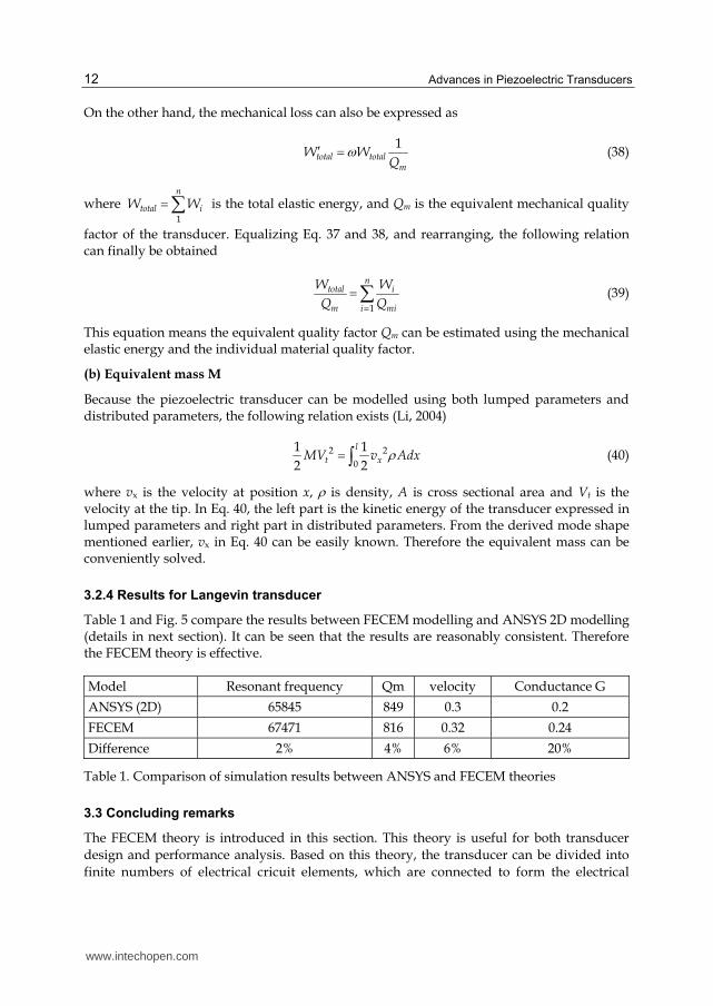
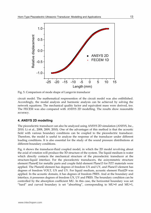
3.2.4 Results for Langevin transducer
Table 1 and Fig. 5 compare the results between FECEM modelling and ANSYS 2D modelling (details in next section). It can be seen that the results are reasonably consistent. Therefore the FECEM theory is effective.
Model Resonant frequency Qm velocity Conductance G
ANSYS (2D) 65845 849 0.3 0.2
FECEM 67471 816 0.32 0.24
Difference 2% 4% 6% 20%
Table 1. Comparison of simulation results between ANSYS and FECEM theories
3.3 Concluding remarks
The FECEM theory is introduced in this section. This theory is useful for both transducer
design and performance analysis. Based on this theory, the transducer can be divided into
finite numbers of electrical cricuit elements, which are connected to form the electrical
www.intechopen.com
Horn-Type Piezoelectric Ultrasonic Transducer: Modelling and Applications
13
-25 -20 -15 -10 -5 0 5 10 15
-1.0
-0.5
0.0
0.5
1.0
ANSYS 2D
FECEM 1D
Re
lative
dis
pla
ce
me
nt
Length (mm)
Fig. 5. Comparison of mode shape of Langevin transducer
circuit model. The mathematical respresention of the circuit model was also estibilished. Accordingly, the modal analysis and harmonic analysis can be achieved by solving the network equations. The mechanical quality factor and equivalent mass were derived, too. The FECEM was also compared with ANSYS 2D modelling. The results show reasonable accuracy.
4. ANSYS 2D modelling
The piezoelectric transducer can also be analyzed using ANSYS 2D simulation (ANSYS, Inc.,
2010; Li et al., 2008, 2009, 2010). One of the advantages of this method is that the acoustic
field with various boundary conditions can be coupled to the piezoelectric transducer.
Therefore, the model is useful to analyze the response of the transducer under different
loading conditions. It is also essential for the study of the sound pressure distributions at
different boundary conditions.
Fig. 6 shows the transducer-fluid coupled model, in which the 2D model revolving about the axial of rotation will produce the 3D structure of the system. The liquid medium is water which directly contacts the mechanical structure of the piezoelectric transducer at the structure-liquid interface. For the piezoelectric transducers, the axisymmetric structure element Plane42 for metallic parts and couple field element Plane13 for PZT materials were applied. The Plane42 element has degrees of freedom UX and UY, and Plane13 element has degrees of freedom VOLT, UX and UY. For liquid medium, acoustic element Fluid29 was applied. In the acoustic domain, it has degrees of freedom PRES. And at the boundary and interface, it possesses degrees of freedom UX, UY and PRES. The boundary condition can be controlled by the absorption coefficient MU. In this case, the horizontal boundary was set “hard” and curved boundary is set “absorbing”, corresponding to MU=0 and MU=1,
www.intechopen.com

Advances in Piezoelectric Transducers
14
respectively. Fig. 6 (b) shows the meshed model of the system. After meshing, an electrical load of 1 V was applied to the PZT stack. To be noted, the transducer analysis and the acoustic analysis can be modelled separately, which might be more efficient for certain problems.
Fig. 6. 2D modelling of the transducer-fluid coupled system, (a) model and (b) meshed model
Fig. 7 shows the harmonic analysis results of the transducer displacement at the resonant
frequency. The colour represents the magnitude of the displacement in the unit of meter.
ANSYS provides the harmonic displacement with the real and imaginary part. Because at
resonance, the electrical excitation and displacement response has 90 deg phase difference,
the imaginary part dominates. It is also noticed that the resonant frequency is 64510 Hz in
the figure, which is different from 65845 Hz in Table 1. This is because the liquid loading
changes the resonant frequency of the transducer.
Fig. 7. Real and imaginary part of the transducer displacement, (a) real, (b) imaginary
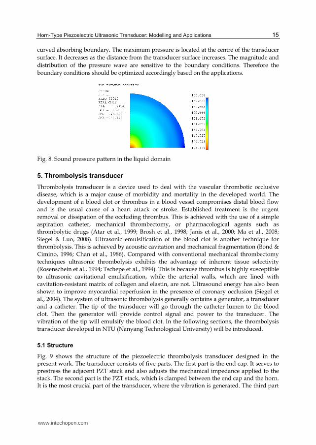
Fig. 8 shows the acoustic pressure distribution in the acoustic field. The colour represents the
magnitude of the pressure wave in the unit of dB. In this case, the transducer-fluid interface is
the pressure wave radiation surface. The horizontal hard boundary resembles an infinite
baffle. A travelling pressure wave is therefore generated at the transducer radiation surface. It
then propagates in the half hemisphere liquid domain. And finally it is fully absorbed at the
Boundaries
Liquid
Axis of
rotation
Interface
PZT Transducer
(a) (b)
(a) (b)
www.intechopen.com
Horn-Type Piezoelectric Ultrasonic Transducer: Modelling and Applications
15
curved absorbing boundary. The maximum pressure is located at the centre of the transducer
surface. It decreases as the distance from the transducer surface increases. The magnitude and
distribution of the pressure wave are sensitive to the boundary conditions. Therefore the
boundary conditions should be optimized accordingly based on the applications.
Fig. 8. Sound pressure pattern in the liquid domain
5. Thrombolysis transducer
Thrombolysis transducer is a device used to deal with the vascular thrombotic occlusive
disease, which is a major cause of morbidity and mortality in the developed world. The
development of a blood clot or thrombus in a blood vessel compromises distal blood flow
and is the usual cause of a heart attack or stroke. Established treatment is the urgent
removal or dissipation of the occluding thrombus. This is achieved with the use of a simple
aspiration catheter, mechanical thrombectomy, or pharmacological agents such as
thrombolytic drugs (Atar et al., 1999; Brosh et al., 1998; Janis et al., 2000; Ma et al., 2008;
Siegel & Luo, 2008). Ultrasonic emulsification of the blood clot is another technique for
thrombolysis. This is achieved by acoustic cavitation and mechanical fragmentation (Bond &
Cimino, 1996; Chan et al., 1986). Compared with conventional mechanical thrombectomy
techniques ultrasonic thrombolysis exhibits the advantage of inherent tissue selectivity
(Rosenschein et al., 1994; Tschepe et al., 1994). This is because thrombus is highly susceptible
to ultrasonic cavitational emulsification, while the arterial walls, which are lined with
cavitation-resistant matrix of collagen and elastin, are not. Ultrasound energy has also been
shown to improve myocardial reperfusion in the presence of coronary occlusion (Siegel et
al., 2004). The system of ultrasonic thrombolysis generally contains a generator, a transducer
and a catheter. The tip of the transducer will go through the catheter lumen to the blood
clot. Then the generator will provide control signal and power to the transducer. The
vibration of the tip will emulsify the blood clot. In the following sections, the thrombolysis
transducer developed in NTU (Nanyang Technological University) will be introduced.
5.1 Structure
Fig. 9 shows the structure of the piezoelectric thrombolysis transducer designed in the present work. The transducer consists of five parts. The first part is the end cap. It serves to prestress the adjacent PZT stack and also adjusts the mechanical impedance applied to the stack. The second part is the PZT stack, which is clamped between the end cap and the horn. It is the most crucial part of the transducer, where the vibration is generated. The third part
www.intechopen.com

Advances in Piezoelectric Transducers
16
of the transducer is the horn, which functions to magnify the displacement produced by the PZT stack. The fourth part is a long and thin transmission wire, which should be flexible but sufficiently stiff for energy transmission. The last part is a distal vibration tip that consists of a ball or a short cylinder with an enlarged diameter (~ 1.5 mm) compared to the connecting transmission wire (~ 0.5 mm). The enlarged diameter increases acoustic power emission to the surrounding liquid and blood clot. The vibration produced by the PZT stack is transmitted through the horn and then the transmission wire to the distal vibration tip. The acoustic energy emitted from the tip is finally used to emulsify the clot.
Fig. 9. Schematic illustration of the piezoelectric thrombolysis device
The transducer operates at ~26.7 kHz longitudinal vibration mode. This is a low ultrasonic
frequency aiming at reducing the heat generation (Francis, 2001; Li et al., 2007b; Siegel et al.,
2000). The diameter of the PZT stack is 10 mm. Maximum input power is 20 W. The length
of transmission wire is 1 m, which is made of a high strength material, Ti-6Al-4V, for
achieving a high vibration velocity (Li et al., 2007b; Mason & Wehr, 1970; Muhlen, 1990). For
practical operations, due to the long length of the transmission wire, the bending mode
could be excited, which would increase loss and decrease the efficiency of the device. To
avoid this, the transmission wire should be coaxial with the horn.
5.2 FECEM modeling
Because of the high aspect ratio of the device (length/diameter), it is very advantageous to
model the device using the FECEM theory. Fig. 10 shows the mode shape of the transducer.
It can be seen that along the axial direction, the displacement generated by the PZT stack is
first amplified by the horn, then further amplified by the transmission wire. As a result, the
tip has a much larger displacement than the PZT stack. Also considering the smaller area of
the vibration tip to the PZT stack, it can be said that the energy produced by the PZT stack
has been focused to the tip through this design. Therefore, the tip will work effectively for
the blood clot emulsification.
5.3 ANSYS 2D acoustic modeling
During practical operation, the vibration tip will be surrounded by liquid and produces an
acoustic field. Fig. 11 shows the simulation of the acoustic field generated by an OD 1.5 mm
and length 3 mm vibration tip. The tip is connected to an OD 0.5 mm transmission wire, and
the vibration frequency of the tip is 30 kHz. The simulation was carried out using ANSYS
2D acoustic analysis. Fig. 11 shows that the maximum ultrasonic pressure is located at the
top and bottom surfaces of the vibration tip, which is normal to the displacement direction.
This indicates that emulsification should be most effective at these locations. The radiation
area multiplied by the normal surface velocity of the tip is known as the source strength
(International standard, IEC 1998; Li et al., 2009). The ultrasonic pressure amplitude is
PZT stack End cap Horn Transmission wire Tip
www.intechopen.com

Horn-Type Piezoelectric Ultrasonic Transducer: Modelling and Applications
17
0.0 0.2 0.4 0.6 0.8 1.0 1.2
-1.5
-1.0
-0.5
0.0
0.5
1.0
1.5
Horn
PZT stack
+
End cap
TipTransmission wire
Rela
tive a
mp
litu
de
Length (m)
Fig. 10. Vibration amplitude distribution along the length of the transducer
proportional to the source strength (International standard, IEC 1998; Li et al., 2009). Therefore, in the present work, a horn is applied to amplify the vibration velocity from the PZT crystal. And a ball or a short cylinder tip is attached at the distal end of the transmission wire to enhance the radiation area.
Fig. 11. Acoustic pressure pattern generated by the tip in the liquid
5.4 Acoustic characterization
The acoustic properties of the transducer were characterized qualitatively. As the acoustic pressure becomes larger and larger, two phenomena might be observed around the tip of the transducer, i.e., cavitation and streaming (Abramov, 1994, 1998; Young, 1999). Cavitation is the generation and burst of bubbles in the liquid due to the high amplitude of the acoustic
www.intechopen.com
Advances in Piezoelectric Transducers
18
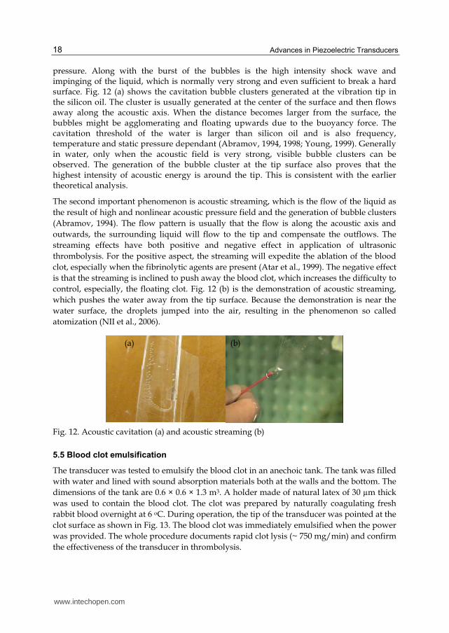
pressure. Along with the burst of the bubbles is the high intensity shock wave and impinging of the liquid, which is normally very strong and even sufficient to break a hard surface. Fig. 12 (a) shows the cavitation bubble clusters generated at the vibration tip in the silicon oil. The cluster is usually generated at the center of the surface and then flows away along the acoustic axis. When the distance becomes larger from the surface, the bubbles might be agglomerating and floating upwards due to the buoyancy force. The cavitation threshold of the water is larger than silicon oil and is also frequency, temperature and static pressure dependant (Abramov, 1994, 1998; Young, 1999). Generally in water, only when the acoustic field is very strong, visible bubble clusters can be observed. The generation of the bubble cluster at the tip surface also proves that the highest intensity of acoustic energy is around the tip. This is consistent with the earlier theoretical analysis.
The second important phenomenon is acoustic streaming, which is the flow of the liquid as
the result of high and nonlinear acoustic pressure field and the generation of bubble clusters
(Abramov, 1994). The flow pattern is usually that the flow is along the acoustic axis and
outwards, the surrounding liquid will flow to the tip and compensate the outflows. The
streaming effects have both positive and negative effect in application of ultrasonic
thrombolysis. For the positive aspect, the streaming will expedite the ablation of the blood
clot, especially when the fibrinolytic agents are present (Atar et al., 1999). The negative effect
is that the streaming is inclined to push away the blood clot, which increases the difficulty to
control, especially, the floating clot. Fig. 12 (b) is the demonstration of acoustic streaming,
which pushes the water away from the tip surface. Because the demonstration is near the
water surface, the droplets jumped into the air, resulting in the phenomenon so called
atomization (NII et al., 2006).
Fig. 12. Acoustic cavitation (a) and acoustic streaming (b)
5.5 Blood clot emulsification
The transducer was tested to emulsify the blood clot in an anechoic tank. The tank was filled
with water and lined with sound absorption materials both at the walls and the bottom. The
dimensions of the tank are 0.6 × 0.6 × 1.3 m3. A holder made of natural latex of 30 µm thick
was used to contain the blood clot. The clot was prepared by naturally coagulating fresh
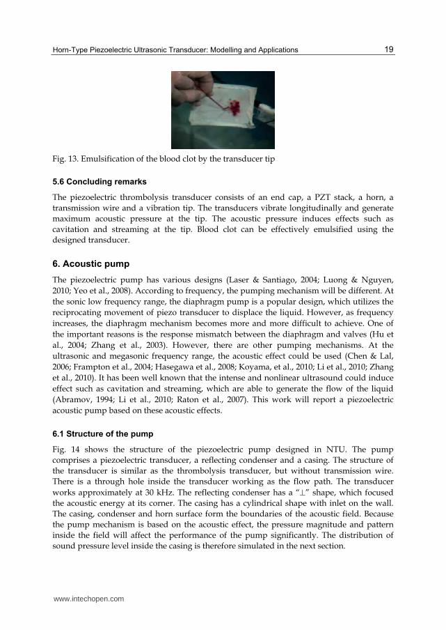
rabbit blood overnight at 6 oC. During operation, the tip of the transducer was pointed at the
clot surface as shown in Fig. 13. The blood clot was immediately emulsified when the power
was provided. The whole procedure documents rapid clot lysis (~ 750 mg/min) and confirm
the effectiveness of the transducer in thrombolysis.
(a) (b)
www.intechopen.com
Horn-Type Piezoelectric Ultrasonic Transducer: Modelling and Applications
19
Fig. 13. Emulsification of the blood clot by the transducer tip
5.6 Concluding remarks
The piezoelectric thrombolysis transducer consists of an end cap, a PZT stack, a horn, a
transmission wire and a vibration tip. The transducers vibrate longitudinally and generate
maximum acoustic pressure at the tip. The acoustic pressure induces effects such as
cavitation and streaming at the tip. Blood clot can be effectively emulsified using the
designed transducer.
6. Acoustic pump
The piezoelectric pump has various designs (Laser & Santiago, 2004; Luong & Nguyen,
2010; Yeo et al., 2008). According to frequency, the pumping mechanism will be different. At
the sonic low frequency range, the diaphragm pump is a popular design, which utilizes the
reciprocating movement of piezo transducer to displace the liquid. However, as frequency
increases, the diaphragm mechanism becomes more and more difficult to achieve. One of
the important reasons is the response mismatch between the diaphragm and valves (Hu et
al., 2004; Zhang et al., 2003). However, there are other pumping mechanisms. At the
ultrasonic and megasonic frequency range, the acoustic effect could be used (Chen & Lal,
2006; Frampton et al., 2004; Hasegawa et al., 2008; Koyama, et al., 2010; Li et al., 2010; Zhang
et al., 2010). It has been well known that the intense and nonlinear ultrasound could induce
effect such as cavitation and streaming, which are able to generate the flow of the liquid
(Abramov, 1994; Li et al., 2010; Raton et al., 2007). This work will report a piezoelectric
acoustic pump based on these acoustic effects.
6.1 Structure of the pump
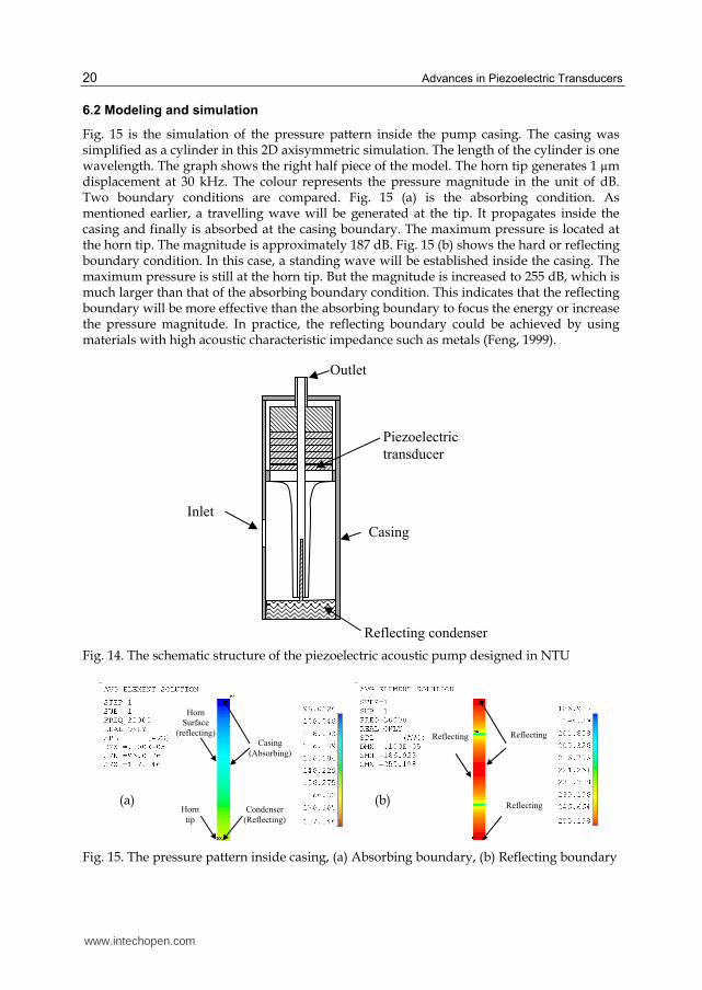
Fig. 14 shows the structure of the piezoelectric pump designed in NTU. The pump
comprises a piezoelectric transducer, a reflecting condenser and a casing. The structure of
the transducer is similar as the thrombolysis transducer, but without transmission wire.
There is a through hole inside the transducer working as the flow path. The transducer
works approximately at 30 kHz. The reflecting condenser has a “” shape, which focused
the acoustic energy at its corner. The casing has a cylindrical shape with inlet on the wall.
The casing, condenser and horn surface form the boundaries of the acoustic field. Because
the pump mechanism is based on the acoustic effect, the pressure magnitude and pattern
inside the field will affect the performance of the pump significantly. The distribution of
sound pressure level inside the casing is therefore simulated in the next section.
www.intechopen.com
Advances in Piezoelectric Transducers
20
6.2 Modeling and simulation
Fig. 15 is the simulation of the pressure pattern inside the pump casing. The casing was simplified as a cylinder in this 2D axisymmetric simulation. The length of the cylinder is one wavelength. The graph shows the right half piece of the model. The horn tip generates 1 µm displacement at 30 kHz. The colour represents the pressure magnitude in the unit of dB. Two boundary conditions are compared. Fig. 15 (a) is the absorbing condition. As mentioned earlier, a travelling wave will be generated at the tip. It propagates inside the casing and finally is absorbed at the casing boundary. The maximum pressure is located at the horn tip. The magnitude is approximately 187 dB. Fig. 15 (b) shows the hard or reflecting boundary condition. In this case, a standing wave will be established inside the casing. The maximum pressure is still at the horn tip. But the magnitude is increased to 255 dB, which is much larger than that of the absorbing boundary condition. This indicates that the reflecting boundary will be more effective than the absorbing boundary to focus the energy or increase the pressure magnitude. In practice, the reflecting boundary could be achieved by using materials with high acoustic characteristic impedance such as metals (Feng, 1999).
Fig. 14. The schematic structure of the piezoelectric acoustic pump designed in NTU
Fig. 15. The pressure pattern inside casing, (a) Absorbing boundary, (b) Reflecting boundary
Inlet
Reflecting condenser
Outlet
Casing
Piezoelectric
transducer
Horn
Surface
(reflecting)
Casing
(Absorbing)
Condenser
(Reflecting)
Horn
tip
Reflecting
Reflecting
Reflecting
(a) (b)
www.intechopen.com
Horn-Type Piezoelectric Ultrasonic Transducer: Modelling and Applications
21
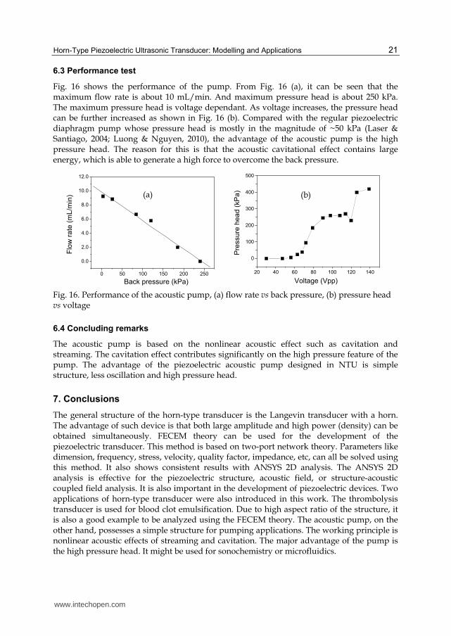
6.3 Performance test
Fig. 16 shows the performance of the pump. From Fig. 16 (a), it can be seen that the maximum flow rate is about 10 mL/min. And maximum pressure head is about 250 kPa. The maximum pressure head is voltage dependant. As voltage increases, the pressure head can be further increased as shown in Fig. 16 (b). Compared with the regular piezoelectric diaphragm pump whose pressure head is mostly in the magnitude of ~50 kPa (Laser & Santiago, 2004; Luong & Nguyen, 2010), the advantage of the acoustic pump is the high pressure head. The reason for this is that the acoustic cavitational effect contains large energy, which is able to generate a high force to overcome the back pressure.
0 50 100 150 200 250
0.0
2.0
4.0
6.0
8.0
10.0
12.0
Flo
w r
ate
(m
L/m
in)
Back pressure (kPa)
20 40 60 80 100 120 140
0
100
200
300
400
500
Pre
ssure
hea
d (
kP
a)
Voltage (Vpp)
Fig. 16. Performance of the acoustic pump, (a) flow rate vs back pressure, (b) pressure head vs voltage
6.4 Concluding remarks
The acoustic pump is based on the nonlinear acoustic effect such as cavitation and streaming. The cavitation effect contributes significantly on the high pressure feature of the pump. The advantage of the piezoelectric acoustic pump designed in NTU is simple structure, less oscillation and high pressure head.
7. Conclusions
The general structure of the horn-type transducer is the Langevin transducer with a horn. The advantage of such device is that both large amplitude and high power (density) can be obtained simultaneously. FECEM theory can be used for the development of the piezoelectric transducer. This method is based on two-port network theory. Parameters like dimension, frequency, stress, velocity, quality factor, impedance, etc, can all be solved using this method. It also shows consistent results with ANSYS 2D analysis. The ANSYS 2D analysis is effective for the piezoelectric structure, acoustic field, or structure-acoustic coupled field analysis. It is also important in the development of piezoelectric devices. Two applications of horn-type transducer were also introduced in this work. The thrombolysis transducer is used for blood clot emulsification. Due to high aspect ratio of the structure, it is also a good example to be analyzed using the FECEM theory. The acoustic pump, on the other hand, possesses a simple structure for pumping applications. The working principle is nonlinear acoustic effects of streaming and cavitation. The major advantage of the pump is the high pressure head. It might be used for sonochemistry or microfluidics.
(a) (b)
www.intechopen.com

Advances in Piezoelectric Transducers
22
8. References
Abramov, O.V. (1994). Ultrasound in Liquid and Solid Metals, CRC Press, ISBN 0849393558, Boca Raton
Abramov, O.V. (1998). High-Intensity Ultrasonics Theory and Industrial Applications, Cordon and Breach Science Publishers, ISBN 9056990411, Russia
Accoto, D.; Carrozza M.C. & Dario P. (2000). Modelling of Micropumps Using Unimorph Piezoelectric Actuator and Ball Valves, J. Micromech. Microeng., Vol.10, No. 2, (June 2000), pp. 277-281, ISSN 0960-1317
ANSYS, Inc. (2010) ANSYS Fluid Analysis Guide and Coupled-Field Analysis Guide, Release 13 APC international, Ltd. (2002). Piezoelectric Ceramics: Principles and Applications, APC
International, Ltd., ISBN 0971874409, Mackeyville Atar, S.; Luo, H.; Nagai, T. and Siegel, R.J. (1999). Ultrasonic Thrombolysis: Catheter-
Delivered and Transcutaneous Applications. European Journal of Ultrasound, Vol.9, No.1 (March 1999), pp. 39–54, ISSN 09298266
Bai, M.R.; Chen R.L.; Chuang C.Y.; Yu C.S. & Hsieh H.L. (2007). Optimal Design of Resonant Piezoelectric Buzzer from a Perspective of Vibration-Absorber Theory, J. Acoust. Soc. Am., Vol.122, No.3, (September 2007), pp. 1568-1580, ISSN 0001-4966
Balabanian, N. & Bickart, T.A. (1981). Linear Network Theory Analysis, Properties, Design and Synthesis, Matrix publisher, Inc., ISBN 0-916460-10-X, Beaverton
Bond, L.J. & Cimino W.W. (1996). Physics of Ultrasonic Surgery Using Tissue Fragmentation, Ultrasonics, Vol. 34, No. 2-5, (June 1996), pp. 579-585, ISSN 0041-624X
Brosh, D.; Miller, H.I.; Herz, I.; Laniado, S. & Rosenschein, U. (1998) Ultrasound Angioplasty: an Update Review, International Journal of Cardiovascular Interventions, Vol.1, No. 1, (January 1998), pp.11-18, ISSN 1462-8848
Chan, K.; Watmough, D.J.; Hope D.T. & MOIR, K. (1986). A New Motor-Driven Surgical Probe and its In Vitro Comparison with the Cavitron Ultrasonic Surgical Aspirator, Ultrasound in Medicine & Biology, Vol.12, No.4, (April 1986), pp.279-283, ISSN 0301-5629
Chen, X. & Lal A. (2006). Theoretical and Experimental Study of a High Flow Rate Ultrasonic Horn Pump, 2006 IEEE Ultrasonics Symposium, pp.2409-2412, ISBN 1-4244-0201-8, Vancouver, BC, October 2-6, 2006
Chen, Y.C. & Wu, S. (2002). A Design Approach of Tonpiltz Transducer, Jpn. J. Appl. Phys., Vol. 41, No.6A, (June 2002), pp. 3866-3877, ISSN 00214922
Chen, Y.C.; Wu, S. & Chen P.C. (2004). The Impedance-Matching Design and Simulation on High Power Electro-acoustical Transducer, Sensors and Actuators A, Vol.115, No. 1, (September 2004), pp.38-45, ISSN 0924-4247
Chu, W.P.; Li, H.L.; Chan, L.W.; Ng, M.W. & Liu C.K. (2002). Smart Ultrasonic Transducer for Wire-Bonding Applications, Materials Chemistry and Physics, Vol. 75, No.1-3 (April 2002), pp.95-100, ISSN 0254-0584
Feng, R. (1999). Ultrasonics Handbook, Nanjing University, ISBN 7-305-03354-5, Nanjing Frampton, K.D.; Minor, K. & Martin, S. (2004). Acoustic Streaming in Micro-Scale
Cylindrical Channels, Applied Acoustics, Vol. 65, No.11, (November 2004), pp.1121-1129, ISSN 0003-682X
Francis, C.W. (2001). Ultrasound-Enhanced Thrombolysis. Echocardiography, Vol. 18, No. 3, (April 2001), pp. 239-246, ISSN 0742-2822
www.intechopen.com
Horn-Type Piezoelectric Ultrasonic Transducer: Modelling and Applications
23
Hasegawa, T.; Koyama D.; Nakamura, K. & Ueha, S. (2008). Modeling and Performance Evaluation of an Ultrasonic Suction Pump, Japanese Journal of Applied Physics, Vol.47, No. 5, (May 2008), pp.4248-4252, ISSN 00214922
Hayt, W.H. & Kemmerly J.E. (1993). Engineering Circuit Analysis (Sixth edition), McGRAW-HILL, Inc., ISBN 0-07-228364-5, New York
Hongoh, M.; Yoshikuni, M.; Miura, H.; Miyamoto, R.; Ueoka T. & Tsujino, J. (2004) Configuration of a 30-mm-Diameter 94 kHz Ultrasonic Longitudinal Vibration System for Plastic Welding, Japanese Journal of Applied Physics, Vol.43, No.5b, (May 2004), pp.2896-2900, ISSN 0021-4922
Horita, R.E. (1967). Free-Flooding Unidirectional Resonators for Deep- Ocean Transducers, The Journal of the Acoustical Society of America, Vol.41, No.1, (January 1967), pp.158-166
Hu, M.; Du, H.J.; Ling, S.F.; Fu, Y.Q.; Chen, Q.F.; Chow, L. & Li, B. (2004). A Silicon-on-Insulator Based Micro Check Vavle, J. Micromech. Microeng., Vol.14, No.3, (March 2004) pp.382-387, ISSN 0960-1317
International standard, IEC 61847, (1998-01). Ultrasonics-Surgical Systems-Measurement and Declaration of the Basic Output Characteristics
Janis, A.D.; Buckely, L.A. & Gregory, K.W. (2000). Laser Thrombolysis in an In-Vitro Model, Proc. SPIE - The International Society for Optical Engineering, Vol.3907, pp.582-599, ISSN 0277-786X, San Jose, CA, USA, January 22-25, 2000
Kapila, V.; Deymier, P.A.; Shende, H.; Pandit, V.; Raghavan S. & Eschbach, F.O. (2006). Megasonic Cleaning, Cavitation, and Substrate Damage: an Atomistic Approach, Proc. Of SPIE - The International Society for Optical Engineering, Vol.6283, pp.628324-1- 12, ISSN 0277-786X, Yokohama, Japan, April 18, 2006
Khmelev, V.N.; Tchyganok,S.N.; Barsukov, R.V. & Lebedev, A.N. (2005). Design and Efficiency Analysis of Half-Wave Piezoelectric Ultrasonic Oscillatory Systems, 6th International Siberian workshop and tutorial EDM’2005, Session II, pp.82-85, ISBN 5778204914, Erlagol, July 1-5, 2005
Koyama, D.; Wada, Y.: Nakamura, K.; Nishikawa, M.; Nakagawa, T. & Kihara, H. (2010). An Ultrasonic Air Pump Using an Acoustic Travelling Wave Along a Small Air Gap, IEEE Transactions on Ultrasonics, Ferroelectrics, and Frequency Control, Vol.57, No.1, (January 2010), pp.253-261, ISSN 0885-3010
Laser, D.J. & Santiago J.G. (2004). A Review of Micropumps, J. Micromech. Microeng., Vol.14, No.6, (June 2004), pp.R35-R64, ISSN 0960-1317
Lee, D.R. & Loh, B.G. (2007). Smart Cooling Technology Utilizing Acoustic Streaming, IEEE Transactions on Components and Packaging Technologies, Vol.30, No.4, (December 2007), pp.691-699, ISSN 1521-3331
Li, Tao (2004). Development of Piezoelectric Tubes for Micromotor, PhD thesis, Nanyang Technological University
Li, Tao; Chen, Y.H.; Ma, J. & Boey F.Y.C. (2007a). Metal-PZT Composite Piezoelectric Transducers and Ultrasonic Motors, Key Engineering Materials, Vol.334-335, (2007) pp. 1073-1076, ISSN 1013-9826
Li, Tao; Chen, Y.H. & Ma, J. (2007b). Frequency Dependence of Piezoelectric Vibration Velocity, Sensors and Actuators A, Vol.138, No.2, (August 2007) pp.404-410, ISSN 0924-4247
www.intechopen.com
Advances in Piezoelectric Transducers
24
Li, Tao; Chen, Y.H.; Boey, F.Y.C. & Ma, J. (2007c). High Amplitude Vibration of Piezoelectric Bending Actuators, J. Electroceram, Vol.18, No.3-4, (August 2007), pp.231-242, ISSN 13853449
Li, Tao; Chen, Y.H. & Ma, J. (2008). Development of Miniaturized Piezoelectric Multimode Transducer for Projection Purpose, Advanced Materials Research, Vol.47-50, (2008) pp.61-64, ISSN 10226680
Li, Tao; Chen, Y.H. & Ma, J. (2009). Development of a Miniaturized Piezoelectric Ultrasonic Transducer, IEEE Transactions on Ultrasonics, Ferroelectrics, and Frequency Control, Vol.56, No.3, (March 2009), pp. 649-659,ISSN 0885-3010
Li, Tao; Chen, Y.H; Lew F.L. & Ma J. (2010). Design, Characterization, and Analysis of a Miniaturized Piezoelectric Transducer, Materials and Manufacturing Processes, Vol.25, No.4, (April 2010), pp.221-226, ISSN 10426914
Lin, S.Y. (1995). Study on the Multifrequency Langevin Ultrasonic Transducer, Ultrasonics, Vol. 33, No.6, (November 1995), pp.445-448, ISSN 0041-624X
Lin, S.Y. (2004a). Effect of Electric Load Impedances on the Performance of Sandwich Piezoelectric Transducers, IEEE Trans. Ultrason., Ferroelec., Freq. Contr., Vol.5, No.10 (October 2004), pp.1280-1286, ISSN 0885-3010
Lin, S.Y. (2004b). Ultrasonic Transducer Principle and Design, Science Press, ISBN 7-03-013419-2, Beijing
Lin, Z.M. (1987). Ultrasonic Horn Principle and Design, Science press, ISBN 7-03-000008-0, Beijing
Luong, T.D. & Nguyen N.T. (2010). Surface Acoustic Wave Driven Microfluidics - A Review, Micro and Nanosystems, Vol.2, No.3, (2010) pp.217-225, ISSN 18764029
Ma, J., Low F.H.A. & Boey Y.C.F. (2010) Micro-Emulsifier for Arterial Thrombus Removal, PCT/SG2008/000323, WO 2010/027325 A1
Mason, W.P. (1964). Physical Acoustics Principles and Methods, Volume I - Part A, Academic Press, ISBN 0124779018, New York
Mason, W.P. & Wehr J. (1970). Internal Friction and Ultrasonic Yield Stress of the Alloy 90 Ti 6 Al 4 V, J. Phys. Chem. Solids, Vol.31, No.8, (August 1970), pp.1925-1933, ISSN 0022-3697
Mattiat, O.E. (1971), Ultrasonic Transducer Materials, Plenum Press, ISBN 0306305011, New York
Medis, P.S. & Henderson H.T. (2005). Micromachining Using Ultrasonic Impact Grinding, J. Micromech. Microeng., Vol.15, No. 8, (August 2005), pp.1556-1559, ISSN 0960-1317
Miclea, C.; Tanasoiu, C.; Iuga, A.; Spanulescu, I.; Miclea, C.F.; Plavitu, C.; Amarande, L.; Cioangher, M.; Trupina, L.; Miclea, C.T. & Tanasoiu, T. (2008). A High Performance PZT Type Material Used as Sensor for an Audio High Frequency Piezoelectric Siren, 2008 International Semiconductor Conference, pp.185-188, ISBN 978-1-4244-2004-9, Sinaia, Romania, October 13-15, 2008
Minchenko, H. (1969). High-Power Piezoelectric Transducer Design, IEEE Transactions on Sonics and Ultrasonics, Vol. SU-16, No. 3, (July 1969), pp.126-131, ISSN 0018-9537
Muhlen, S.S. (1990). Design of an Optimized High-Power Ultrasonic Transducer, 1990 IEEE Ultrasonics Symposium, pp.1631-1634, Honolulu, HI , USA, December 04-07, 1990
NII, S.; Matsuura, K.; Fukazu, T.; Toki, M. & Kawaizumi F. (2006). A Novel Method to Separate Organic Compounds through Ultrasonic Atomization, Chemical
www.intechopen.com

Horn-Type Piezoelectric Ultrasonic Transducer: Modelling and Applications
25
Engineering Research and Design, Vol.84, No.5A, (May 2006), pp.412-41, ISSN 02638762
Prokic, M. (2004). Piezoelectric Transducers Modeling and Characterization, MPI, Switzerland Radmanovic, M.D. & Mancic D.D. (2004). Design and Modelling of the Power Ultrasonic
Transducers, MPI, ISBN 86-80135-87-9, Switzerland Rosenschein, U.; Frimerman, A.; Laniado S. & Miller, H.I. (1994). Study of the Mechanism of
Ultrasound Angioplasty from Human Thrombi and Bovine Aorta, Am. J. Cardiol., Vol.74, No.12, (December 1994), pp.1263-1266, ISSN 0002-9149
Sherrit, S.; Dolgin, B.P.; Bar-Cohen, Y.; Pal, D.; Kroh J. & Peterson, T. (1999a). Modeling of Horns for Sonic/Ultrasonic Applications, 1999 IEEE Ultrasonics Symposium, pp.647-651, ISBN 0-7803-5722-1, Caesars Tahoe, NV, USA, October 17-20, 1999
Sherrit, S.; Leary, S.P.; Dolgin B.P. & Bar-Cohen Y. (1999b). Comparison of the Mason and KLM Equivalent Circuits for Piezoelectric Resonators in the Thickness Mode, 1999 IEEE Ultrasonics Symposium, pp.921-926, ISBN 0-7803-5722-1, Caesars Tahoe, NV, USA, October 17-20, 1999.
Siegel, J.; Atar, S.; Fishbein, M.C.; Brasch, A.V.; Peterson, T.M.; Nagai, T.; Pal, D.; Nishioka, T.; Chae, J.S.; Birnbaum, Y.; Zanelli, C. & Luo, H. (2000). Noninvasive, Transthoracic, Low-frequency Ultrasound Augments Thrombolysis in a Canine Model of Acute Myocardial Infarction, Circulation, Vol.101, No.17 (May 2000) pp.2026-2029, ISSN 1524-4539
Siegel, J. & Luo, H. (2008). Ultrasound Thrombolysis, Ultrasonics, Vol.48, No.4, (August 2008) pp.312-320, ISSN 0041-624X
Siegel, R.J., Suchkova, V.N.; Miyamoto, T.; Luo, H.; Baggs, R.B.; Neuman, Y.; Horzewski, M.; Suorsa, V.; Kobal, S.; Thompson, T.; Echt D.; & Francis, C.W. (2004) Ultrasound Energy Improves Myocardial Perfusion in the Presence of Coronary Occlusion, J. Am. Coll. Cardiol., Vol.44, No.7, (October 2004), pp.1454-1458, ISSN 0735-1097
Silva, C.W.D. (1999). Vibration Fundamentals and Practice, CRC Press, ISBN 0849318084, New York
Tschepe, J.; Aspidov, A.A.; Helfmann J. & Herrig, M. (1994). Acoustical Waves via Optical Fibers for Biomedical Applications, Proc. SPIE- Biomedical Optoelectronic Devices and Systems, Vol.2084, pp.133-143, ISBN 9780819413512, Budapest, Hungary, 01 September 01, 1993
Tsuda, Y.; Mori E. & Ueha, S. (1983). Experimental Study of Ultrasonic Surgical Knife, Jpn. J. Appl. Phys., Vol.22, Supplement 22-3 (1983) pp.105-107, ISSN 0021-4922
Uchino, K. & Giniewicz J.R. (2003). Micromechatronics, CRC Press, ISBN 0824741099, New York
Wiksell, H.; Martin, H.; Coakham, H.; Berggren A. & Westermark, S. (2000). Miniaturized Ultrasonic Aspiration Handpiece for Increased Applicability, Eur. J. Ultrasound, Vol. 11, No.1, (March 2000), pp.41-46, ISSN 09298266
Woias, P.; Micropumps - Past, Progress and Future Prospects, Sensors and Actuators B, Vol.105, No.1, (February 2005), pp.28-38, ISSN 0925-4005
Yeo, C.Y.; Shim, W.K.; Wouterson, E.; Li, Tao & Ma, J. (2008). Piezoelectric Materials for Impedance Driven Micro-Channel Flow, Functional Materials Letters, Vo.1, No.3, (2008), pp.225-228
Young, F.R. (1999). Cavitation, Imperial College Press, ISBN 1860941982, Singapore
www.intechopen.com
Advances in Piezoelectric Transducers
26
Zhang, A.L & Wei, Y.Q. (2010). Generation of Droplets for Lab-on-a-Piezoelectric-Substrate Utilizing Surface Acoustic Wave, Proceedings of the 2010 symposium on piezoelectricity, acoustic waves, and device applications (SPAWDA 2010), pp.68-71, ISBN 978-1-4244-9822-2 ,Xiamen, China, December 10-13, 2010
Zhang, J.H.; Wang, D.K.; Wang, S.Y. & Qnuki, A. (2003). Research on Piezoelectric Pump-Lagging of Valve, Chinese Journal of Mechanical Engineering, Vol.39, No.5, (May 2003), pp.107-110, ISSN 05776686
www.intechopen.com
Advances in Piezoelectric TransducersEdited by Dr. Farzad Ebrahimi
ISBN 978-953-307-931-8Hard cover, 128 pagesPublisher InTechPublished online 25, November, 2011Published in print edition November, 2011
InTech EuropeUniversity Campus STeP Ri Slavka Krautzeka 83/A 51000 Rijeka, Croatia Phone: +385 (51) 770 447 Fax: +385 (51) 686 166www.intechopen.com
InTech ChinaUnit 405, Office Block, Hotel Equatorial Shanghai No.65, Yan An Road (West), Shanghai, 200040, China
Phone: +86-21-62489820 Fax: +86-21-62489821
The piezoelectric transducer converts electric signals into mechanical vibrations or vice versa by utilizing themorphological change of a crystal which occurs on voltage application, or conversely by monitoring the voltagegenerated by a pressure applied on a crystal. This book reports on the state of the art research anddevelopment findings on this very broad matter through original and innovative research studies exhibitingvarious investigation directions. The present book is a result of contributions of experts from internationalscientific community working in different aspects of piezoelectric transducers. The text is addressed not only toresearchers, but also to professional engineers, students and other experts in a variety of disciplines, bothacademic and industrial seeking to gain a better understanding of what has been done in the field recently,and what kind of open problems are in this area.
How to referenceIn order to correctly reference this scholarly work, feel free to copy and paste the following:
Tao Li, Jan Ma and Adrian F. Low (2011). Horn-Type Piezoelectric Ultrasonic Transducer: Modelling andApplications, Advances in Piezoelectric Transducers, Dr. Farzad Ebrahimi (Ed.), ISBN: 978-953-307-931-8,InTech, Available from: http://www.intechopen.com/books/advances-in-piezoelectric-transducers/horn-type-piezoelectric-ultrasonic-transducer-modelling-and-applications

© 2011 The Author(s). Licensee IntechOpen. This is an open access articledistributed under the terms of the Creative Commons Attribution 3.0License, which permits unrestricted use, distribution, and reproduction inany medium, provided the original work is properly cited.