Embed Size (px)
Citation preview

GRUNDFOS INSTRUCTIONS
Horizontal Split CaseModel AEFInstallation and operating instructions

En
glis
h (U
S)
English (US) Installation and operating instructions
Original installation and operating instructions.
CONTENTSPage
1. Symbols used in this document
2. General informationThese instructions should be retained for reference regarding maintenance and operation near the pump.
These are general instructions and may not take into account local regulations. The user should ensure such regulations are observed by all parties.
Information in this manual is believed to be reliable. In spite of all the efforts to provide sound and all necessary information, the content of this manual may appear insufficient and is not guaranteed to be compete or accurate in all instances.
2.1 Warranty
This unit is manufactured under a quality management system standard as certified and audited by external quality assurance organizations. Genuine parts and accessories have been designed, tested and incorporated into the products to help ensure their continued product quality and performance in use.
Damage or failure caused by misuse, abuse or failure to follow these instructions are not covered by our warranty.
Any modification of our products or removal of original components may impair the safety of these products in their use.
2.2 Personnel qualification
All operations must be carried out by qualified personnel.
1. Symbols used in this document 2
2. General information 22.1 Warranty 22.2 Personnel qualification 22.3 Warnings 32.4 Material Safety Data Sheet 4
3. Transport and storage 43.1 Transport and handling requirements 43.2 Receipt and inspection 43.3 Rigging and lifting 53.4 Storage 53.5 Disposal of packaging materials 6
4. Identification 64.1 Nameplate 64.2 Type key for horizontal split case fire pump 7
5. Installation 95.1 Factory support 95.2 Location 95.3 Foundation 95.4 Rigging and lifting 105.5 Installation preparations 115.6 Base plate or pump 115.7 Piping and connections 125.8 Setting the impeller clearance 125.9 Alignment 135.10 Lubrication, priming and cooling systems 155.11 Electrical installation 155.12 Control, monitoring and alarm equipment 15
6. Startup, operation and shutdown 156.1 Frost protection 156.2 Lubrication 156.3 Rotation 166.4 Guards 166.5 Check list 166.6 Startup, operation and shutdown 17
7. Maintenance 187.1 Schedule 187.2 Recommended spare parts 187.3 Consumables 187.4 Tightening torques 187.5 Dismantling 197.6 Wear Ring 207.7 Inspection and Repair 207.8 Assembly 217.9 Accessories 21
8. Fault finding (Trouble Shooting) 22
9. Parts list and sectional drawing 24
10. Disposal 25
Warning
Prior to installation, read these installation and operating instructions. Installation and operation must comply with local regulations and accepted codes of good practice.
Warning
If these safety instructions are not observed, it may result in personal injury.
Warning
If these instructions are not observed, it may lead to electric shock with consequent risk of serious personal injury or death.
Warning
When pumping hazardous liquids, special attention must be paid to the risk of personal injury.
Warning
The surface of the product may be so hot that it may cause burns or personal injury.
Warning
The sound pressure level is so high that hearing protection must be used.
CautionIf these safety instructions are not observed, it may result in malfunction or damage to the equipment.
NoteNote Notes or instructions that make the job easier and ensure safe operation.
2

En
gli
sh
(U
S)
2.3 WarningsWarning
If the site is left unattended before the installation is complete, all openings must be covered to prevent entry of children, animals, stones or any other foreign objects.
Use unbreakable covers that cannot be removed without tools.
Warning
When a pump has experienced temperatures over 400 °F [205 °C], skin contact must be avoided with components. Additionally, partial decomposition of fluoro-elastomers (when fitted) will occur.
Warning
Many precision parts have sharp corners and the wearing of appropriate safety gloves and equipment is required when handling these components.
Warning
Hot or freezing components or auxiliary heating supplies can present a danger to operators and persons entering the immediate area. Action must be taken to avoid accidental contact. If complete protection is not possible, the machine access must be limited to maintenance staff only, with clear visual Warnings and indicators to those entering the immediate area.
Warning
Rapid changes in the liquid temperature can cause thermal shock that can result in damage of pump components and should be avoided.
Warning
When the pump is handling hazardous liquids, care must be taken to avoid exposure to the liquid by appropriate setting of the pump, limiting personnel access and by operator training. If the liquid is flammable and/or explosive, strict safety procedures must be applied.
Gland packing must not be used when pumping hazardous liquids.
Caution
Do not use pump as a support for piping.
Do not mount expansion joints, unless allowed by Peerless Pump in writing, so that their force, due to internal pressure, acts on the pump flange.
Caution
Products used in potentially explosive atmospheres. Special consideration must be taken when pumps are installed in these applications. Contact Peerless Pump for more information.
Warning
Parts which are provided with lifting lugs, lifting ears or eyebolts should be lifted by these points only. They may not be used for lifting the entire pump.
When lifting the entire pump, use appropriate slings.
Warning
Do not attempt to lift the entire pump by the lifting lugs (eyes) of the driver or pump.
Never lift unit using hooks or slings on shafts.
Use proper lifting techniques when manually lifting components -keep component close to body, back straight, lift with legs, DO NOT BEND AT WAIST.
Warning
Do not work under suspended object unless you have taken precautions to stop its fall in the event of sling failure.
Do not place hands under component in such a way that the component would fall on the hands if dropped.
Warning
Pumps are not designed to accept external loads from belt driven arrangements. A separate jack-shaft with a bearing structure suitable for belt loading is required.
Warning
Do not remove or paint over any safety labels. If labels are lost or damaged, contact your Peerless Pump representative for replacement.
Warning
Never do maintenance work when the unit is connected to power.
Warning
All guards must be in place on the pump prior to startup. Read and follow all recommended guarding and safety instructions for accessories, if any.
Warning
Do NOT place fingers, hands, arms, etc. into any opening (such as the air relief valve hole).
Do NOT wear loose or frayed clothing or jewelry that could catch on equipment or become trapped in the equipment.
Do NOT touch the impeller or other rotating elements, if rotated, this can cause severe injury.
The area between the stuffing box and bearing bracket is left open to allow for inspection and adjustment of packing. Do NOT place hands or fingers into this area while equipment is in operation. Do NOT wear loose clothing, long hair, or jewelry around this area.
Warning
Use only qualified electricians for electrical installation and maintenance.
Refer to manuals provided with electrical accessory components and disconnect power supply as recommended for servicing.
3

En
glis
h (U
S)
2.4 Material Safety Data Sheet
As a general practice, material safety data sheets (MSDS) are not supplied with pumps unless required. They may be requested from Peerless Pump.
2.4.1 Noise level
3. Transport and storage
3.1 Transport and handling requirements
The pump has been prepared for shipment at the factory in such a way as to minimize potential damage due to handling and transport.
3.2 Receipt and inspection
Receiver should report any shortage or damage to the transport company handling the shipment and to Peerless Pump.
Prior to installation, take inventory of the shipment to ensure that the parts received match the list of parts on your order.
Note the extent of damage or shortage on the freight bill and bill of lading. Failure to note damage or missing parts may result in declined warranty or replacement of parts.
It is important that all the components for a pump unit be identified and properly stored until installation is to be done.
There may be many small parts (such as line shaft couplings or hardware) that are best left in their shipping container until installation.
Do not unpack any more than required to verify that the equipment is complete and undamaged unless installation is to be done immediately. Check all packaging material that is to be discarded to verify that no parts or instructions are being accidentally discarded. In some shipments, small boxes containing additional parts are bound to pump skids. Leave small parts in their shipping container until installation so they don't get lost. Upon unpacking make certain that accessories with a pump unit are clearly marked showing which pump unit they are to be used with.
Warning
Most surfaces on the driver (engine or motor) can become hot during normal operation.
If packing is too tight, the drain water from the stuffing box can become hot enough to scald. Ensure that drain water is not excessively hot before contact.
The stuffing box and bearing bracket areas on the pump can become hot in the event of a malfunction or maladjustment. These surfaces may remain hot for some time after the unit has been shut down.
Use care when touching these surfaces and wear protective gloves if necessary to touch these surfaces when hot.
Warning
Noise levels, especially for diesel engine driven units, can exceed safe levels. Refer to the noise level published in the accompanying documentation, and, if this noise level exceeds local code or safe levels, place the unit in a controlled access area and provide ear protection to personnel authorized to be in this area.
Fire pump units can start unexpectedly at any time. Ear protection should be carried by, or readily available to, all personnel authorized to be in the pump room with these units.
Warning
Isolate engine before any maintenance work is done. Switch off the main supply, remove fuses, secure fuel lines, apply lock-outs where applicable, and affix suitable isolation warning signs to prevent inadvertent re-connection.
ISOLATE the fuel supply to the engine BEFORE working on any part of the fuel supply or control system
DISCONNECT the batteries by removal of the NEGATIVE terminal connector. Do NOT place tools on or near the batteries. This could result in a short circuit. INSPECT all cables for damage or signs of failure and replace immediately if damaged.
Warning
Engine fuel fumes are highly flammable! Do NOT refuel the engine when it is running or is still hot from recent running.
When refueling, avoid breathing the fuel fumes, particularly if the pump; is installed in an enclosed pump room. Maintain maximum ventilation to clear the fumes quickly.
Do NOT start the engine while fuel fumes remain evident or may be present.
Warning
Exhaust gases are hazardous; the exhaust system MUST be maintained free from leaks and directed to discharge in a safe area.
Warning
Battery gasses are hazardous and flammable. The battery area MUST be well ventilated to clear these gases quickly.
Warning
Do NOT store lubricants or other volatile substances near the engine. These should be placed in a designated area having a suitable storage enclosure.
Warning
Whenever pump noise level exceeds 85 dBA, attention must be given to the prevailing health and safety legislation to limit the exposure of plant operating personnel to the noise. The usual approach is to control exposure time to the noise or to enclose the machine to reduce emitted sound.
CautionThe equipment should not be subjected to excessive g-forces during the handling or transport.
4

En
gli
sh
(U
S)
3.3 Rigging and liftingWhen pumps are received unassembled, all the parts should be located close to the location where the pump will be installed.
3.4 Storage
Standard factory packaging is suitable for protection during shipment and during covered storage at jobsite for a short period between installation and startup. The preservatives applied at the factory have an effective life of two to three months from date of shipment from factory, depending on the severity of the environment in which the equipment is exposed. For international destination this will vary depending on the sea worthiness of export boxing.
3.4.1 Controlled storage
Storage facilities should be maintained at an even temperature of at least 10 °F [5.5 °C] above the dew point with relative humidity lower than 50 % and little or no dust. The equipment is to be inspected weekly to ensure that all preservatives are intact and internals are protected.
Inspect and recoat periodically the equipment with water displacement rust inhibitors (VPCI-368-021, Rust-Ban 392 or equal), crusting grease (Rust-Ban 326 or equal), vapor phase inhibitor (Shell VPI-260 or equal) or rust preventative coating (Rust-Ban 373 or equal).
3.4.2 Uncontrolled storage
For uncontrolled storage periods of three months or less, the equipment is to be inspected weekly to ensure that all preservatives are intact and internals are protected.
Inspect and recoat periodically the equipment with water displacement rust inhibitors (Rust-Ban 392 or equal), crusting grease (Rust-Ban 326 or equal), vapor phase inhibitor
(Shell VPI-260 or equal) and/or rust preventative coating (Rust-Ban 343 or equal).
All pipe threads and flanged pipe covers are to be sealed with tape. Furthermore you should place 10 lbs. [4.5 kg] of moisture-absorbing desiccant or 5 lbs. [2.3 kg] of vapor phase inhibitor crystals near the centre of pump.
If the pump is assembled, place an additional one pound in the discharge of the pump securely fastened.
Install a moisture indicator near the perimeter of the pump.
Cover the equipment with black polyethylene or equal with a minimum thickness of 0.006" [0.15 mm]. Provide a small ventilation hole approximately the size of a small coin.
Provide a roof or shed shelter to protect from direct exposure to the elements.
If equipped, connect space heaters on equipment such as motors, engines or controls.
3.4.3 Standard short-term storage
The pump and equipment, as shipped, have adequate protection for short-term (two to three months) storage in a covered, dry and ventilated location at the job site prior to installation.
For short-term (two to three months) storage not in a covered, dry and ventilated location at the job site prior to installation. For packed-type pumps, remove stuffing box packing and place it in a sealed plastic bag. Apply a film of compatible lube oil over the water displacement rust preventative (Rust-Ban 632 or equal). Seal the end of the stuffing box with rolled vapor phase inhibitor paper and seal with weatherproof tape. For packed-type pumps the packing glands may be left on the pump shaft, but should be securely fastened in position.
All exposed machined surfaces should be thoroughly coated with a firm film rust preventative material (Rust-Ban 373 or equal) that is readily removable with a petroleum distillate product.
All exposed painted surfaces should be dry, clean and free of grease and other contaminates.
After pump has been thoroughly drained, cover the pump suction and discharge flanges with a cover (typically cardboard or wood) to blank off these openings.
Rotate pump shaft per the rotation arrow on pump several revolutions at least once per week to coat the bearing with lubricant and to retard oxidation and corrosion, flat spots and staining. Shaft should end up 90 ° from starting point.
To place the pump in operation, all protective coverings and coatings should be properly removed. For packed-type pumps, repack the stuffing box with the proper number of packing rings from bag. If the packing appears to be damaged or otherwise unfit, it should be replaced.
See section 3.4.4 Long-term storage when the startup of equipment is made over three months from the date of shipment from the factory.
Caution
Pump parts that are too heavy to be lifted by hand must be lifted from the transporting vehicle with a suitable hoist. Lifting chains or cables must not contact machined surfaces.
Warning
Parts which are provided with lifting lugs, lifting ears or eyebolts should be lifted by these points only. They may not be used for lifting the entire pump.
When lifting the entire pump, use appropriate slings.
Warning
Do not attempt to lift the entire pump by the lifting lugs (eyes) of the driver or pump.
Never lift unit using hooks or slings on shafts.
Use proper lifting techniques when manually lifting components -keep component close to body, back straight, lift with legs, DO NOT BEND AT WAIST.
Warning
Do not work under a suspended object unless you have taken precautions to stop its fall in event of sling or hoist failure.
Caution
Protect the equipment from flooding or from harmful chemical vapors.
Storage should be free from ambient vibration. Excessive vibration can cause bearing damage.
Precautions should be taken to prevent rodents, snakes, birds or insect from nesting inside the equipment.
5

En
glis
h (U
S)
3.4.4 Long-term storage
Long-term storage protection from the factory does not extend the warranty in any manner. Warranty policy is twelve months from startup or eighteen months from time of shipment, whichever occurs first. This warranty is valid only if equipment has been properly handled and stored as per the stated requirements.
Should the equipment be stored or handled improperly, then the warranty is invalid and may be reinstated only after a factory representative is allowed to inspect the equipment prior to startup. Expenses for the representative will be billed in accordance with the latest schedule for field service engineer.
Any repairs or repair parts needed will be billed to the customer at prices in effect at time of shipment of these repairs/parts.
At the time of pump specification and/or order placement
Peerless Pump should be advised about the extended storage duration so that special long-term storage protection can be provided for the equipment prior to shipping to the job site.
Inspection of the equipment by a factory representative prior to startup is normally required to ensure equipment integrity and compliance with warranty requirements.
In addition to complying with the standard short-term and storage atmosphere conditions, the following considerations are required:
Dry pump internals and spray the liquid end with a water displacement rust inhibitor (Rust-Ban 392 or equal).
Enclose vapor inhibitor in pump internals (Shell VPI 260 or equal).
Apply a film of compatible lube oil over the water displacement rust preventative (Rust-Ban 632 or equal).
After pump has been thoroughly drained, cover the pump suction and discharge flanges with full natural rubber gasket material and blank off these openings with metal blank flanges and a minimum of four full sized bolts. Cover the pump stuffing box opening with a non-hygroscopic tape.
Cover the equipment with black polyethylene or equal with a minimum thickness of 0.006" [0.15 mm] and seal it with tape.
Provide a small ventilation hole approximately the size of a small coin.
The pump should be inspected at regular periods.
Rotate the pump shaft per the rotation arrow on the pump several revolutions at least once per week to coat the bearing with lubricant and to retard oxidation and corrosion, flat spots and staining. The shaft should end up 90 ° from starting point.
To place the pump in operation, all protective coverings and coatings should be properly removed. For packed-type pumps, repack the stuffing box with the proper number of packing rings from bag. If the packing appears to be damaged or otherwise unfit, it should be replaced.
3.4.5 Accessories storage
Store accessories according to the manufacturer's instructions.
Long-term storage should not be undertaken without written understanding from manufacturer.
3.5 Disposal of packaging materials
See section 10. Disposal.
4. Identification
4.1 Nameplate
Each pump has a nameplate which list serial number. See fig. 1 and 2 for pump supplied. The serial number is needed when contacting Peerless Pump with questions or service request.
When a driver is supplied, there will also be a nameplate on the driver. When requesting information about the driver, both the driver serial number and the pump serial number will be required.
Information on the Fire pump nameplate includes the following:
• pump size/model
• serial number
• pump manufacturer and location
• certification mark (UL/FM fire or other), if any
• rated flow rate
• rated speed
• rated head
• rated psi
• impeller diameter.
Fig. 1 Fire pump Nameplate
Fig. 2 Flange Nameplate
Information on the flange name plate includes the following:
• pump size/model
• serial number
• pump manufacture and location.
4.1.1 Certifications
If the product carries an industry certification (UL/FM fire or other), it will be noted on the pump nameplate. Contact Peerless Pump for additional information.
4.1.2 Pump
The pump size/model is given with a number, letter(s) followed by a number such as 5AEF12. These would represent the size and model of pump.
TM
06
02
90
511
3T
M0
6 0
21
7 5
113
CENTRIFUGAL FIRE PUMPHORIZONTAL SPLIT-CASE
SerialModel
6

En
gli
sh
(U
S)
4.2 Type key for horizontal split case fire pumpCode Example 6AEF16G 1-A-1/7-P-A-B-R-C
6 AEF 16 G -1 -A -1 /7 -P -A -B -R -C
Discharge Flange
Model
Maximum Impeller Diameter [inches]
Hydraulic Variation<> - None (blank)G - ….….
Flange Rating1 - 125#x125#2 - 125#x250#3 - 250#x250#4 - 125#x400#X - Special
Listing or Approval of Pump SystemA - UL and FMB - FM onlyC - UL onlyD - NFPA compliantE - ULCF - CCCX - Special
Casing Material1 - Cast Iron2 - Ductile Iron4 - 316LSS5 - CD4MCu9 - Nickel-Aluminium BronzeX - Special
Impeller Material1 - Cast Iron4 - 316LSS5 - CD4MCu7 - Silicon Bronze9 - Nickel-Aluminium BronzeX - Special
Type of SealingP - PackingS - Seal Component StyleC - Cartridge SealX - Special
System ConfigurationA - Bare Shaft PumpB - Pump + BaseC - Pump + Base + DriveD - Pump + Base + Driver + ControllerX - Special
7

En
glis
h (U
S)
Manufacture of DriverB - USEM / NidecC - General ElectricD - MarathonE - WEGF - BaldorN - ClarkeP - CumminsQ - CaterpillarR - DeutzZ - No DriverX - Special
Pump RotationR - Right Hand / ClockwiseL - Left Hand / Counter Clockwise
Controller Type:A - No PanelC - FiretrolD - TornatechE - MasterF - Cutler HammerX - Special
6 AEF 16 G -1 -A -1 /7 -P -A -B -R -C
8

En
gli
sh
(U
S)
5. Installation5.1 Factory support
For customized products, we recommend that you have a
Peerless Pump service engineer supervise installation and startup.
This is to ensure that the machinery is properly installed. You will then also have the opportunity to review, and see implemented, factory-recommended instructions.
5.2 Location
5.3 Foundation
The pump must be installed on a foundation rigid enough to support the entire weight of the pump plus the weight of the fluid contained in it. Weak foundations or foundations on unstable ground can cause misalignment, vibration, and even total foundation failure.
The mass of the foundation should be sufficient, preferably five times that of the rotating element of the pumping equipment, to form a permanent and rigid support for the base plate.
Foundation and base plate bolt sizing is critical, particularly on high-pressure pumps, to adequately restrain reaction forces such as from directional flow change, system transients and sudden valve closure. Concrete foundations may have anchor bolts installed in sleeves that are two times the diameter of the bolt to allow alignment and should be located by a drawing or template.
Whether the base plate is installed prior to the pump installation or at the same time, the pump must be attached to the base plate. Check that the pump feet are clean and free of burrs and nicks.
Failure to have each component's surface machined will result in excessive vibration.
Follow the instructions in sections 5.4.1 Leveling and 5.4.2 Grouting. After the grout is cured (a minimum of 48 hours), the pump unit may be finished for pump installation. Peerless Pump does not recommend installation of the base plate without the pump.
5.3.1 Seismic analysis
When pumps are located in seismically active areas and for certain critical installations the pumps, supports and accessories should be earthquake-resistant. The design specifications to achieve earthquake resistance vary, depending upon geographical area, class of the equipment (defining how critical the survival of the equipment is) and the characteristics (acceleration response) of the structure or foundation supporting the pump.
Complete specifications for earthquake-resistance requirements should be supplied by the customer. This includes the following:
• the seismic criteria, such as acceleration, magnitudes, frequency spectrum, location and direction relative to pump
• the qualification procedure required, i.e., analysis, testing or a combination of these, and requirements for operability during and/or after test.
Warning
This pumping unit is designed to be operated within certain limits pertaining to fluid pump, driver conditions, etc. These limits are listed on the performance curve, or on original contract documentation.
Do not operate this pump at any pressure, flow rate, or liquid temperature other than those for which the pump was originally purchased. Do not pump any other liquid than the one for which the pump was originally purchased without the consent of Peerless Pump or its authorized representatives. Disregard of this Warning can result in pump failure and serious personal injury or death.
Operation outside of these limits may result in damage to the unit, personal injury, or death. Consult your Peerless Pump representative for approval if a need arises to operate outside of these limits.
Warning
Operation at a reduced capacity for prolonged periods may shorten the useful life of the seals or packing, shaft sleeves, bearings, and the shaft. Fire pumps are applied with full knowledge that operation at reduced capacity will occur.
NoteNote
Locate pump discharge piping and suction piping as well as auxiliary equipment, control and starting panels so that adequate access is provided for maintenance.
Adequate floor space and working room should also be provided for maintenance
NoteNote
To minimize frictional head loss, locate the pump so that it can be installed with a short and direct discharge pipe and with the least number of elbows and fittings. If practical, it should be placed so that it will be accessible for inspection during operation. Pumps, drivers and controls should be protected against flooding, freezing, etc.
NoteNote
The suction supply system must provide the pump with Net Positive Suction Head (NPSH) equal to or greater than that required by the pump at any capacity on its operating curve. Ask your Peerless Pump representative for assistance if; you do not understand how to calculate or measure suction supply system NPSH.
NoteNote
Allowable bearing loads of structural steel and floors can be obtained from engineering handbooks; building codes of local communities give the recommended allowable bearing loads for different types of soil.
Caution
Steel support structures may not be stiff enough even if their mass exceeds five times that of the rotating element. A civil engineer should review and approve a steel support structure before pump installation.
Caution
Position the foundation and the foundation bolts so that pump suction and discharge flanges will be in accurate alignment with the discharge piping.
9

En
glis
h (U
S)
5.4 Rigging and lifting
For typical installations, suitable overhead lifting equipment of adequate capacity to lift the driver, the entire pump (without driver) or the heaviest subassembly of the pump should be available at the job site when installing or removing the pump.
Adequate headroom should be provided to accommodate the pump to be handled, including rigging.
5.4.1 Leveling
1. Remove the supporting timbers, rope and any other equipment from the top of the foundation.
2. Disconnect the coupling halves between the pump and driver.
3. Lower the pump unit until the base plate is just above the foundation bolts.
4. Orient the pump so that the discharge outlet and suction inlet is in the desired direction and the holes in the base align with the foundation bolts.
5. Continue to lower the pump until the bolts just enter the holes in the base.
6. If the foundation is concrete, place the wedges under the base plate, adjacent to the bolt holes, one under each of the four sides.
7. For structural foundations (made up of I-beams or H-beams), use shims under the corners.
8. Continue to slowly lower the pump until the base of the base plate rests on the wedges or anchor bolts with washers and nuts.
9. By using the wedges or washers and nuts on the anchor bolts, adjust the pump suction flange center line to the correct elevation.
10. While maintaining the correct elevation, adjust the nuts and washers or shims to achieve the specified levelness of 0.005" per ft. [0.4 mm per m] in both directions. The levelness should be measured by placing a precision level on the machined face of the discharge flange.
11. Place a machinist's level on the discharge flange, orienting it parallel with one of the edges of the base.
12. Move the wedges or add more shims until the level reading reaches 0.005" per ft. [0.4 mm per m].
13. Reorient the level on the same surface, 90 ° from the original position.
14. Again adjust the wedges or shims until a 0.005" [0.12 mm] level reading is reached, taking care not to upset the levelness is the first direction.
15. After each adjustment, check for levelness in both directions.
16. Push in or add to any loose shims to distribute the weight evenly.
17. Fit nuts on the foundation bolts and tighten them gradually and uniformly.
18. Check the level readings in both directions.
19. If necessary, loosen the foundation bolts and readjust the wedges or shims, tighten the bolts again and check the level
readings.
5.4.2 Grouting
After the base plate is at the correct location and leveled with a precision level, the base plate needs to be grouted to the foundation.
Grout compensates for unevenness in the foundation and base plate and minimizes vibrations levels during operations. It prevents the unit from shifting after mounting and alignment.
Fig. 3 Typical foundation with base plate
Only non-shrinking grouting material should be used for grouting the base plate to the foundation. Foundation bolts should not be fully tightened until the grout is hardened, usually about 48 hours after pouring.
1. Prepare the foundation surface according to the grout manufacturer's recommendations.
2. Locate the foundation bolts by the use of a template frame and provide anchorage as shown in fig. 4. See the outline drawings furnished with each pump for the exact location of the foundation bolts.
3. Build a dam on the foundation, enclosing an area around the base plate that includes all alignment wedges. Allow for a grout thickness of 0.75 to 1.50" thickness [19.05 mm to 38.1 mm]. See fig. 3.
4. Pour the grout through the holes provided in the base plate or through open ends of steel channel base plates. While pouring, tamp liberally in order to fill all cavities and prevent air pockets. If tamping does not eliminate all air pockets, drill small vent holes through the base surface.
5. Level off the grout flush with the top of the dam.
6. Allow the grout to cure at least 48 hours before tightening the foundation bolts or starting the pump.
7. Tighten pipe connections to suction and discharge flanges.
8. Check the pump alignment in Section 5.9 Alignment.
9. When the grout has thoroughly dried, paint the exposed edges to prevent air and moisture from coming in contact with the grout.
Fig. 4 Foundation Bolting Location and Anchorage Mount and leveling
Caution
Properly sized slings, chains and shackles should be available for attaching to the lifting lugs (eyes). Eyebolts are required for handling pump sections when lifting lugs are not provided.
NoteNote
If the base plate is not already grouted in place, be certain that the grouting dam around the foundation opening is in place before lowering the pump assembly onto the foundation.
CautionAccurate alignment of the pump shaft in relation to the motor shaft is absolutely essential for smooth and trouble-free operation.
CautionNever attempt to align the pump using a spirit (carpenter's) level.
TM
06
02
18
49
13
TM
06
02
19
09
14
Cross board for holdingfoundation bolts
Template frame
Foundation boltassembly
Maleable washer
Pipe sleeve
Concrete foundation
Metal wedgeGrout
Flat washerPump base
Nut
Foundation bolt
10

En
gli
sh
(U
S)
5.5 Installation preparations5.5.1 Inspection
All pump parts were carefully inspected before leaving the factory, but may have become soiled or damaged in shipping and handling or storage at site. The installer must therefore check that all parts are clean and undamaged before installing them.
Use appropriate solvent to wash off any protective coating from the shaft sections and wipe thoroughly clean and dry.
Dirt, sand, etc. in the system will cause premature wear on the critical pump internal surfaces, resulting in reduced pump performance.
Pumps and drivers mounted on a common base plate were accurately aligned before shipment. All base plates are flexible to some extent and, therefore, must not be relied upon to maintain the factory alignment.
Realignment is necessary after the complete unit has been leveled on the foundation and again after the grout has set and foundation bolts have been tightened. The alignment must be checked after the unit is piped and rechecked periodically as outlined in the following paragraphs. To facilitate accurate field alignment, we do not dowel the pumps or drivers on the base plates before shipment.
5.5.2 Engine Preparation
Safe and efficient operation of a pumping unit driven by an diesel engine, requires the installation to satisfy the following requirements:
1. It is recommended that the operator become familiar with the installation and service manual supplied by the engine manufacturer or Peerless Pump
2. Be well ventilated in order to keep the ambient temperature as low as possible. Taking 60 °F [15.6 °C] as a datum point, every 10 °F [-12 °C] rise in temperature reduces the horsepower of the engine by approximately 1 %.
3. Provide ample air for proper combustion.
4. Provide the engine with an efficient exhaust system so that the combustion gasses discharge with a minimum of backpressure.
5. Provide for a fuel system of adequate capacity that meets the local codes.
6. Provide ample accessibility to service engine.
7. Provide correct rotation of the pump. Engine rotation is determined at the factory. No change of engine rotation can be made in the field.
5.6 Base plate or pump
5.6.1 Leveling
Flat surfaces that might capture air during grouting should be vented to prevent voids between the surface and the grout.
The base plate should be leveled by use of wedges (see section 5.4.1 Leveling) or by use of leveling screws supported on rectangular metal blocks.
The leveling screw threads should be covered with a non-binding material such as grease, putty or tape before grouting, to facilitate their removal.
If shims are used, they should be placed to isolate from the initial application of grout. After the initial grout has cured, the forms and shims may be removed and the void filled with a second application of grout.
A gap of about 0.75 to 1.5" [19.05 mm to 38.1 mm] should be allowed between the base plate and the foundation for grouting. See section 5.2 Location.
5.6.2 Grouting
The grout material that supports the base plate is a critical element of the pump support structure and should be carefully selected. The product warranty is void if this Instruction is not followed.
If the grout cracks or fails, the structure will be compromised. When the alignment is correct, the foundation bolts should be tightened evenly but not too firmly. The unit can then be grouted to the foundation. It is not recommended to grout leveling pieces, shims or wedges in place because they introduce discontinuities and stress concentrations that may cause the grout to crack. Foundation bolts should not be fully tightened until the grout is hardened, usually about 48 to 72 hours after pouring. Jacking screws should be removed after the grout has hardened and the holes filled with an appropriate sealing material.
5.6.3 Doweling
Contact Peerless Pump for further information.
CautionDo not step or walk on the pump components. Do not place other parts or equipment on the pump components.
Warning
Never attempt to lift the pump by means of eyebolts screwed into the driver mounting holes because the bolts are not strong enough to carry the weight of the entire pump.
CautionDo not distort the base plate by over tightening the foundation bolts.
11

En
glis
h (U
S)
5.7 Piping and connections
5.7.1 Pipe supports, anchors or joints
Suction and discharge piping should be anchored, supported and restrained near the pump to avoid application of forces and moments to the pump in excess of those permitted by Peerless Pump.
In order to achieve optimum operation and minimum noise and vibration, consider vibration dampening of the pump.
Noise and vibration are generated by the revolutions of the motor and pump and by the flow in pipes and fittings. The effect on the environment is subjective and depends on correct installation and the state of the remaining system.
Elimination of noise and vibrations is best achieved by means of a concrete foundation, vibration dampers and expansion joints.
The pump should also be inspected internally for foreign matter that may have entered the pump.
Fig. 5 Piping Arrangement
5.7.2 Vibration dampers
To prevent the transmission of vibrations to buildings, isolate the pump foundation from building parts by means of vibration dampers.
The selection of the right vibration damper requires the following data:
• forces transmitted through the damper
• motor speed considering speed control, if any
• required dampening in %.
The selection of vibration damper differs from installation to installation. In certain cases, a wrong damper may increase the vibration level. Vibration dampers should therefore be sized by the supplier of the vibration dampers.
If you install the pump on a foundation with vibration dampers, always fit expansion joints on the pump flanges. This is important to prevent the pump from "hanging" in the flanges.
5.7.3 Suction piping
The suction and discharge piping should be of sufficient size and be internally free of foreign material.
Considerations for suction piping to achieve optimal performance are:
1. When operating under suction lift, line must be kept absolutely free from air leaks.
2. When operating under suction lift, must be at least one pipe diameter larger than the pump suction nozzle. In order to prevent eddies and vortices, the end of the suction pipe must be at least two pipe diameters below the free liquid surface. If a foot valve is used to facilitate priming, the foot valve must have a minimum flow area 1.5 times the area of the suction pipe. The suction at all points and should not contain loops or high spots in which air can be trapped.
3. When operating under suction pressure, pipe may be equal to, but never less than the suction nozzle size.
Failure of the suction piping to deliver the liquid to the pump in this condition can lead to noisy operation, swirling of liquid around the suspended pump assembly, premature bearing failure and cavitation damage to the impeller and inlet portions of the casing.
Contact Peerless Pump for further information.
5.7.4 Suction valves and manifolds
Block valves may be installed to isolate the pump for maintenance.
Foot valves are specially designed non-return valves sometimes used at the inlet to prevent backspin caused by rapidly draining water in the discharge pipe.
5.7.5 Discharge valves
A non-return valve and an isolation valve should be installed in the discharge pipe. The non-return valve serves to protect the pump from backflow and excessive backpressure. The isolation valve is used when starting and stopping the pump.
We recommend closing the isolation valve before stopping or starting the pump.
Pump backspin and hydraulic shock can cause severe damage to pump and motor. Install at least one non-return valve in the discharge pipe, not more than 25 ft. [7.5 m] after the discharge flange to help prevent this
Operating some pumps at shutoff may cause a dangerous increase in pressure or power. If increasers are used on the discharge side of the pump to increase the size of piping, they should be placed between the non-return valve and the pump.
If expansion joints are used, they should be placed between the pipe anchor and the non-return valve.
5.7.6 Nozzle loads
The piping should be aligned with the pump nozzles to minimize pump nozzle loads. Contact Peerless Pump for allowable nozzle loading for your given design.
5.8 Setting the impeller clearance
To achieve optimal performance and reduce radial loading, the impeller should be centered in the volute passageway of the casing. For new pumps, this is done at the factory, refer to section 7.6 Wear Ring.
CautionDo not exceed the forces or moments specified on the outline drawing when connecting piping to the suction or discharge flanges.
Caution
Piping must be independently supported and arranged so that expansion and contraction, due to temperature changes, will not cause misalignment.
NoteNote
Piping should be cleaned mechanically and chemically, and flushed prior to installing the pump. A large number of pump packing, seal and seizure troubles are due to improperly cleaned systems.
TM
06
02
20
09
14
1 2
3 4
Incorrect
CorrectCorrect
Correct
CorrectCorrect
Incorrect
Incorrect
IncorrectPath of water
Air pocket
Air pocket
Air pocket
12

En
gli
sh
(U
S)
5.9 AlignmentPumps and drivers mounted on a common base plate were accurately aligned before shipment. All base plates are flexible to some extent and, therefore, must not be relied upon to maintain the factory alignment.
After the grout has set and the foundation bolts have been properly tightened, the unit alignment should be checked.
After the piping of the unit has been connected, the alignment should be checked again. Alignment may be checked by mounting a dial indicator to measure shaft movement before and after tightening flange bolts. If the unit does not stay in alignment after being properly installed, the following are possible causes:
• setting, seasoning or springing of the foundation
• excessive pipe strain distorting or shifting the machine
• settling of the building
• shifting of pump or driver on the base plate or foundation
To facilitate accurate field alignment, we do not dowel the pumps or drivers on the base plates before shipment.
Reliable, trouble-free, and efficient operation of a pumping unit requires correct alignment of pump and driver shafts.
Misalignment may be the cause of:
• Noisy pump operation
• Vibration
• Premature bearing failure
• Excessive coupling wear
Recheck alignment is required after:
• Mounting
• Grout has hardened
• Foundation bolts are tightened or readjusted
• Piping is connected or adjusted
• Pump, driver or base plate is moved for any reason
The procedure for alignment verification for units with the pump and driver connected by a flexible coupling, mounted on a common base are:
1. Disconnect the coupling halves.
2. Set the coupling gap to the dimension shown in fig. 6, 7, or on outline drawings.
Fig. 6 Coupling misalignment
CouplingMax RPM
Parallel in. [mm]
Angularity in. [mm]
Weight lb. [kg]
Torquelb-in. [Nm]
1020 4500 0.006 [0.15] 0.003 [0.08] 4.2 [1.9] 460 [52]
1030 4500 0.006 [0.15] 0.003 [0.08] 5.7 [2.6] 1,320 [149]
1040 4500 0.006 [0.15] 0.003 [0.08] 7.4 [3.4] 2,200 [249]
1050 4500 0.008 [0.2] 0.004 [0.1] 12 [5.4] 3,850 [435]
1060 4350 0.008 [0.2] 0.005 [0.13] 16 [7.3] 6,050 [684]
1070 4125 0.008 [0.2] 0.005 [0.13] 23 [10.4] 8,800 [994]
1080 3600 0.008 [0.2] 0.006 [0.15] 39 [17.7] 18,150 [2,051]
1090 3600 0.008 [0.2] 0.007 [0.18] 56 [25.4] 33,000 [3,729]
1100 2440 0.01 [0.25] 0.008 [0.2] 93 [42.2] 55,550 [6,276]
1110 2250 0.01 [0.25] 0.009 [0.23] 120 [54.4] 82,500 [9,321]
1120 2025 0.011 [0.28] 0.01 [0.25] 179 [81.2] 121,000 [13,671]
1130 1800 0.011 [0.28] 0.012 [0.3] 266 [120.7] 176,000 [19,885]
1140 1650 0.011 [0.28] 0.013 [0.33] 392 [177.8] 253,000 [28,585]
Falk/Clarke/Dodge Coupling Misalignment
TM
06
02
21
49
13
- T
M0
6 0
22
2 4
91
3
X
Y P
P
Angular misalignment Parallel misalignment
13

En
glis
h (U
S)
Fig. 7 E distance
3. Test for parallel and angular alignment with a straight edge and feeler gauge as shown in manufacturer's instructions (at the end of this section). With coupling halves stationary, make trials at four places 90 ° apart. Perfect alignment occurs when a straight edge is level across the coupling halves and the same gauge just enters between the halves, both conditions at all points.
4. An alternate test for parallel and angular alignment may be made with a dial indicator mounted as shown in fig. 8.
• Scribe the index lines on the coupling halves (as shown) or mark where the indicator point rests.
• Set indicator dial to zero.
• Slowly turn BOTH coupling halves so that index lines match, or indicator point is always on the mark.
• Observe dial reading to determine whether pump or driver needs adjustment.
• Acceptable parallel and angular alignment occurs when total indicator reading (complete turn) does not exceed limits shown on either a tag or decal on the unit or on the unit outline drawing.
Fig. 8 Dial indicator figure
5. When significant operating temperature differential will exist between the pump and driver (i.e. steam turbine drive with pump handling cold liquid), thermal growth will cause the hotter unit to rise. Compensate for this growth by initially setting the hotter unit 0.003" to 0.005" [0.076 mm to 0.127 mm] low. When both units are at normal operating temperature, a final check of coupling alignment must be made. Correct the alignment if necessary.
6. NOTE Check for correct electric motor rotation as described in the two bullet points under paragraph 6.3 below while coupling halves are disconnected.
7. Correct for excessive parallel and angular misalignment by slightly shifting the leveling wedges under the base plate. Tap lightly (in or out) with a hammer. Retest alignment after each shifting of a wedge.
8. In some instances, for factory-aligned pumping units, it may be necessary to change the shims under the pump or driver, or even relocate these factory-positioned units on the base plate. Make such changes only after it is certain alignment cannot be obtained by shifting of the wedges.
9. If wedges are shifted or shims changed a substantial amount to obtain proper alignment, recheck the piping alignment and level of the shafts.
ROTEX Size
E distance in. [mm]
Max Parallelin. [mm]
Max Angularityin. [mm]
Max. axial in. [mm]
14 0.51 [13] 0.006 [0.15] 1.1 [28] -0.02 [-0.5] +0.04 [1]
19 0.63 [16] 0.007 [0.18] 1 [25] -0.02 [-0.5] +0.05 [1.3]
24 0.71 [18] 0.008 [0.2] 0.08 [2] -0.02 [-0.5] +0.06 [1.5]
28 0.79 [20.1] 0.009 [0.23] 0.09 [2] -0.03 [-0.8] +0.06 [1.5]
38 0.94 [23.9] 0.01 [0.25] 0.09 [2] -0.03 [-0.8] +0.07 [1.8]
42 1.02 [25.9] 0.011 [0.28] 1 [25] -0.04 [-1] +0.08 [2]
48 1.1 [27.9] 0.013 [0.33] 1.1 [28] -0.04 [-1] +0.08 [2]
55 1.18 [30] 0.014 [0.36] 1.1 [28] -0.04 [-1] +0.09 [2.3]
65 1.38 [35.1] 0.015 [0.38] 1.1 [28] -0.04 [-1] +0.1 [2.5]
75 1.57 [39.9] 0.017 [0.43] 1.1 [28] -0.06 [-1.5] +0.12 [3]
90 1.77 [45] 0.018 [0.46] 1.2 [30] -0.06 [-1.5] +0.13 [3.3]
100 1.97 [50] 0.019 [0.48] 1.2 [30] -0.06 [-1.5] +0.15 [3.8]
110 2.17 [55.1] 0.02 [0.51] 1.2 [30] -0.08 [-2] +0.17 [4.3]
125 2.36 [59.9] 0.021 [0.53] 1.2 [30] -0.08 [-2] +0.18 [4.6]
140 2.56 [65] 0.022 [0.56] 1.2 [30] -0.08 [-2] +0.2 [5.1]
160 2.95 [74.9] 0.022 [0.56] 1.2 [30] -0.1 [-2.5] +0.22 [5.6]
180 3.35 [85.1] 0.024 [0.61] 1.2 [30] -0.12 [-3] +0.25 [6.4]
KTR Coupling Chart Gap and Maximum MisalignmentT
M0
6 1
15
6 1
71
4
E
TM
06
02
23
49
13
Fixture
Inside micrometer
Dial indicator
14

En
gli
sh
(U
S)
5.9.1 Auxiliary (driver, coupling, etc)Engine drivers
Engine driven unit are typically supplied with pump and drive on a common base plate. For units that are supplied separate, contact Peerless Pump.
1. Check the axial misalignment between pump and engine.
2. Check parallel alignment.
3. Check the angle between the pump shaft and driver when coupled has a Maximum angle of 3 degrees. Consult Manufacture.
4. At least 3/4 of the key is engaged with the coupler and the shaft.
5. Installation of universal drive see manufacturer's Instructions
5.10 Lubrication, priming and cooling systems
If supplied, please see additional documents attached to the pump or contact Peerless Pump.
5.11 Electrical installation
Electrical conduit and boxes should be located to avoid obstruction of pump unit.
A plot of speed versus torque requirements during the starting phase of a pump can be checked against the speed versus torque curve of the driving motor. Contact the drive manufacture for curve availability. The driver should be capable of supplying more torque at each speed than required by the pump in order to accelerate the pump up to rated speed. This condition is generally easily attainable with standard induction or synchronous motors, but under certain conditions, such as high-specific-speed pumps over 5000 US units [100 metric units] or reduced voltage starting, a motor with high pull-in torque may be required. To achieve a smooth start for the pumping equipment, autotransformers may be connected to the starting panel or solid state starters used. These provide a gradual increase in voltage up to rated voltage, ensuring even acceleration.
5.12 Control, monitoring and alarm equipment
All control and alarm systems should be checked for correct installation and functioning in accordance with the manufacturer's instructions. All alarm point settings should be checked.
5.12.1 Stopping the unit/reverse runaway speed
A sudden power and/or discharge valve failure during pump operation against a static head will result in a flow reversal, and the pump will operate as a hydraulic turbine in a direction opposite to that of normal pump operation.
If the driver offers little resistance while running backwards, the rotational speed may approach the pump-specific speed.
This condition is called runaway speed and causes mechanical problems. Contact Peerless Pump for aid in preventing this condition.
6. Startup, operation and shutdown
If the conditions of service on you purchase order are going to be changed, (for example liquid pumped, temperature or duty), seek written agreement from Peerless Pump.
6.1 Frost protection
If the pump is to be used in area where there is a potential of freezing or frost, necessary steps should be taken to protect pump and cooling systems from freezing and bursting.
6.2 Lubrication
Before attempting to start the pump, check the following items:
• lubrication fitting at packing (if applicable)
• lubrication for pump bearing
• lubrication of the driver
• oil-cooling connections for the driver (if applicable)
• coupling (if required by manufacturer)
Good practice includes the following:
• Keep lubricant clean. Provide, and use, a dust tight cover on the storage container.
• Use the oldest lubricant first.
• Clean pump lubricant fittings before re-lubricating with grease.
• Use clean dispensing equipment.
• Remove 0.25" [6.4 mm] drain pipe plug on bottom outside of bearing housing cover. Inject clean, new grease, forcing out the old through the drain opening.
• Start and run the pump for a short time to eject any excess grease. Reinstall 0.25" [6.4 mm] pipe plug. Wipe off ejected grease.
• Use the proper amount of lubricant -too much result in churning, unnecessary power consumption, rapid heating to a high temperature and inadequate lubrication.
Warning
The pump must not be operated beyond the parameters specified for the application. If there is any doubt as to the suitability of the product for the application intended, have the serial number ready and contact Peerless Pump for advice.
NoteNote
Normal bearing temperatures vary with the seasons and environment and may range from 0 to approximately 250 °F [-18 to 121 °C]. A continuous rise from the established, normal operating temperature indicates trouble and probable failure of the bearing. Shut down the pump immediately.
15
En
glis
h (U
S)
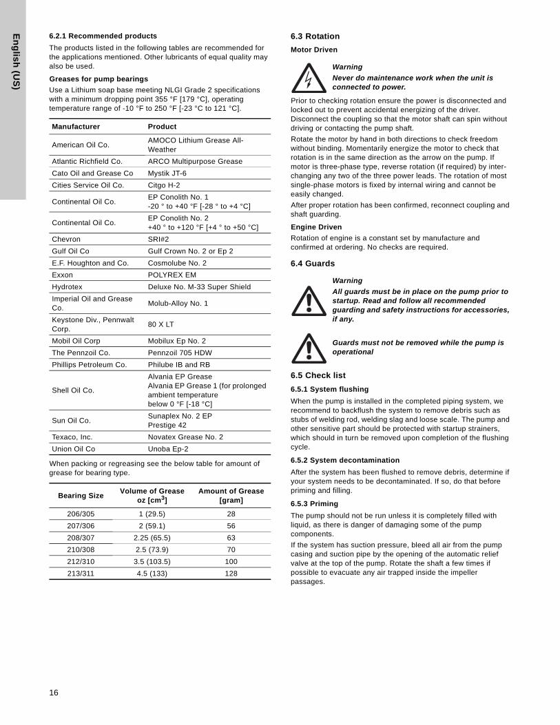
6.2.1 Recommended products
The products listed in the following tables are recommended for the applications mentioned. Other lubricants of equal quality may also be used.
Greases for pump bearings
Use a Lithium soap base meeting NLGI Grade 2 specifications with a minimum dropping point 355 °F [179 °C], operating temperature range of -10 °F to 250 °F [-23 °C to 121 °C].
When packing or regreasing see the below table for amount of grease for bearing type.
6.3 Rotation
Motor Driven
Prior to checking rotation ensure the power is disconnected and locked out to prevent accidental energizing of the driver. Disconnect the coupling so that the motor shaft can spin without driving or contacting the pump shaft.
Rotate the motor by hand in both directions to check freedom without binding. Momentarily energize the motor to check that rotation is in the same direction as the arrow on the pump. If motor is three-phase type, reverse rotation (if required) by inter-changing any two of the three power leads. The rotation of most single-phase motors is fixed by internal wiring and cannot be easily changed.
After proper rotation has been confirmed, reconnect coupling and shaft guarding.
Engine Driven
Rotation of engine is a constant set by manufacture and confirmed at ordering. No checks are required.
6.4 Guards
6.5 Check list
6.5.1 System flushing
When the pump is installed in the completed piping system, we recommend to backflush the system to remove debris such as stubs of welding rod, welding slag and loose scale. The pump and other sensitive part should be protected with startup strainers, which should in turn be removed upon completion of the flushing cycle.
6.5.2 System decontamination
After the system has been flushed to remove debris, determine if your system needs to be decontaminated. If so, do that before priming and filling.
6.5.3 Priming
The pump should not be run unless it is completely filled with liquid, as there is danger of damaging some of the pump components.
If the system has suction pressure, bleed all air from the pump casing and suction pipe by the opening of the automatic relief valve at the top of the pump. Rotate the shaft a few times if possible to evacuate any air trapped inside the impeller passages.
Manufacturer Product
American Oil Co. AMOCO Lithium Grease All- Weather
Atlantic Richfield Co. ARCO Multipurpose Grease
Cato Oil and Grease Co Mystik JT-6
Cities Service Oil Co. Citgo H-2
Continental Oil Co. EP Conolith No. 1 -20 ° to +40 °F [-28 ° to +4 °C]
Continental Oil Co.EP Conolith No. 2 +40 ° to +120 °F [+4 ° to +50 °C]
Chevron SRI#2
Gulf Oil Co Gulf Crown No. 2 or Ep 2
E.F. Houghton and Co. Cosmolube No. 2
Exxon POLYREX EM
Hydrotex Deluxe No. M-33 Super Shield
Imperial Oil and Grease Co.
Molub-Alloy No. 1
Keystone Div., Pennwalt Corp.
80 X LT
Mobil Oil Corp Mobilux Ep No. 2
The Pennzoil Co. Pennzoil 705 HDW
Phillips Petroleum Co. Philube IB and RB
Shell Oil Co.
Alvania EP Grease Alvania EP Grease 1 (for prolonged ambient temperature below 0 °F [-18 °C]
Sun Oil Co. Sunaplex No. 2 EP Prestige 42
Texaco, Inc. Novatex Grease No. 2
Union Oil Co Unoba Ep-2
Bearing SizeVolume of Grease
oz [cm3]Amount of Grease
[gram]
206/305 1 (29.5) 28
207/306 2 (59.1) 56
208/307 2.25 (65.5) 63
210/308 2.5 (73.9) 70
212/310 3.5 (103.5) 100
213/311 4.5 (133) 128
Warning
Never do maintenance work when the unit is connected to power.
Warning
All guards must be in place on the pump prior to startup. Read and follow all recommended guarding and safety instructions for accessories, if any.
Guards must not be removed while the pump is operational
16
En
gli
sh
(U
S)
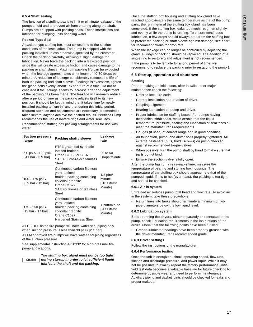
6.5.4 Shaft sealingThe function of a stuffing box is to limit or eliminate leakage of the pumped fluid and to prevent air from entering along the shaft. Pumps are equipped with packing seals. These instructions are intended for pumping units handling water.
Packed Type Seal
A packed type stuffing box must correspond to the suction conditions of the installation. The pump is shipped with the packing installed unless otherwise specified by the customer. Check the packing carefully, allowing a slight leakage for lubrication. Never force the packing into a leak-proof position since this will create excessive friction and cause damage to the packing or shaft sleeve. Maximum packing life can be expected when the leakage approximates a minimum of 40-60 drops per minute. A reduction of leakage considerably reduces the life of both the packing and shaft sleeve. If leakage is excessive, tighten the gland bolts evenly, about 1/6 of a turn at a time. Do not be confused if the leakage seems to increase after and adjustment of the packing has been made. The leakage will normally reduce after a period of time as the packing adjusts itself to its new position. It should be kept in mind that it takes time for newly installed packing to "run-in" and that during this initial period, frequent attention and adjustments are necessary. It sometimes takes several days to achieve the desired results. Peerless Pump recommends the use of lantern rings and water seal lines.
Recommended stuffing box packing arrangements for use with water
All UL/ULC listed fire pumps will have water seal piping only when suction pressure is less than 30 psiG [2.1 bar].
All FM approved fire pumps will have water seal piping regardless of the suction pressure.
See supplemental instruction 4850332 for high-pressure fire pump applications.
Once the stuffing box housing and stuffing box gland have reached approximately the same temperature as that of the pump parts, the running-in of the stuffing box gland has been completed. If the stuffing box leaks too much, retighten slightly and evenly while the pump is running. To ensure continuous lubrication, a few drops should always drop from the stuffing box to protect the packing or shaft sleeve against damage, see chart for recommendations for drop rate.
When the leakage can no longer be controlled by adjusting the gland, all rings of packing should be replaced. The addition of a single ring to restore gland adjustment is not recommended.
If the pump is to be left idle for a long period of time, we recommend to replace the packing prior to restarting the pump 1.
6.6 Startup, operation and shutdown
Starting
Prior to making an initial start, after installation or major maintenance check the following:
• Refer to local fire code.
• Correct installation and rotation of driver.
• Coupling alignment.
• Bearing lubrication on pump and driver.
• Proper lubrication for stuffing boxes. For pumps having mechanical shaft seals, make certain that the liquid temperature, pressure, cooling and lubrication of seal faces all meet the manufacturer's requirements
• Gauges (if used) of correct range and in good condition.
• All foundation, pump, and driver bolts properly tightened. All external fasteners (nuts, bolts, screws) on pump checked against recommended torque values.
• When possible, turn the pump shaft by hand to make sure that parts do not bind.
• Ensure the suction valve is fully open.
After the pump has run a reasonable time, measure the temperature of bearing and stuffing box housings. The temperature of the stuffing box should approximate that of the pumped liquid. If it is to hot (overheats), the packing is too tight and should be checked.
6.6.1 Air in system
Entrained air reduces pump total head and flow rate. To avoid air in the system, take these precautions:
• Return lines into tanks should terminate a minimum of two pipe diameters below the low liquid level.
6.6.2 Lubrication system
Before running the drivers, either separately or connected to the pump, check lubrication requirements in the instructions of the driver. Check that the following points have been fulfilled:
• Grease-lubricated bearings have been properly greased with the driver manufacturer's recommended grade.
6.6.3 Driver settings
Follow the instructions of the manufacturer.
6.6.4 Performance testing
Once the unit is energized, check operating speed, flow rate, suction and discharge pressure, and power input. While it may not be possible to exactly repeat the factory performance, initial field test data becomes a valuable baseline for future checking to determine possible wear and need to perform maintenance. Auxiliary piping and gasket joints should be checked for leaks and proper makeup.
Suction pressure range
Packing shaft / sleeveLeakage rate
6.0 psiA - 100 psiG[.41 bar - 6.9 bar]
PTFE graphited synthetic latticed braidedCrane C1065 or C1070SAE 40 Bronze or Stainless Steel
20 to 50 Drops/Minute
100 - 175 psiG[6.9 bar - 12 bar]
Continuous carbon filament yarn, latticedbraided packing containing colloidal graphiteCrane C1627SAE 40 Bronze or StainlessSteel
1/3 pint/minute[.16 Liters/Minute]
175 - 250 psiG[12 bar - 17 bar]
Continuous carbon filament yarn, latticedbraided packing containing colloidal graphiteCrane C1627Hardened Stainless Steel
1 pint/minute[.47 Liters/Minute]
CautionThe stuffing box gland must not be too tight during startup in order to let sufficient liquid lubricate the shaft and the packing.
17

En
glis
h (U
S)
7. Maintenance
7.1 Schedule
To ensure satisfactory operation of the pumping equipment, frequent inspection and periodic maintenance are required.
An inspection and maintenance log should be kept and the inspector is to immediately report any problems. A suggested guide for preventative maintenance for normal applications is given below. Unusual applications with abnormal heat, moisture, dust, etc., may require more frequent inspection and service.
7.2 Recommended spare parts
The list of recommended spare parts will depend on factors such as the following:
• Normal supplier lead time when ordering parts.
• If pumping equipment is for use as normal duty or severe duty, and if there is backup pumping while a unit is down for maintenance and parts replacement.
Below is a suggested list of spare parts.
For intermittent or non-critical service
• Stuffing box packing (Item 13
• Ball Bearing Set (Item 16 and 18)
• Bearing Seal Set (Item 47 and 169)
• Bearing Cover Gaskets (Item 73B)
• Set of Shaft Sleeves (Item 14 and 14A)
• Set of Sleeve O-Rings (Item 14B)
• Set of Casing Rings (Item 7)
• Set of Impeller Rings, if supplied (Item 8)
• Gasket, Casing (Item 73A)
• Packing gland and studs or gland bolts.
For continuous or critical service (in addition to above)
• Complete Rotating Element preassembled.
7.3 Consumables
Items normally used in the maintenance of pumping equipment may include the following, but depending on the type of unit some items may vary:
• Lubricant (grease or oil)
• Cleaning materials
• Touch-up coating.
• Hand tools
• Measuring equipment (feeler gauges, dial indicator, etc.)
7.4 Tightening torques
Proper tightening of fasteners is very important. The torque values depend on the size and grade of the fasteners used.
The values in the table below apply to non-lubricated parts.
When assembling a pump, cross-tighten the screws in order to avoid misalignment, binding and leakage.
Torque value shown are for clean lubricated threads and gasket joints.
Warning
Never do maintenance work when the unit is connected to power.
Warning
Do not attempt to lift the entire pump by the lifting lugs (eyes) of the driver or pump.
Warning
Do not work under suspended object unless you have taken precautions to stop its fall in the event of sling failure
Item Action Frequency
Packing, packing box
Inspect for excessive leakage
First 150 hours of operation, then every 2000 hours of operation or quarterly
Packing, packing box
Adjust gland and replace packing
As necessary
Pump-motor alignment
Check for change in alignment
Annually
VibrationCheck for change in vibration
Annually
Bearings
Lubricate (grease)• Light Duty,
approximately 10 hour/week
• Normal Duty, approximately 8 hour/day
• Sever Duty, approximately 24 hour/day
• Every 2000 hours or at least once a year
• Every 2000 hours or at least every six months
• Monthly
Fasteners Check for loose fasteners Annually
Fastener sizeTorque lb-ft [Nm]
Torque lb-ft [Nm]
Fastener Size in. [mm]
MEDIUMCARBONSTEELSAEJ429GRADE5105-120,000PSITENSILE
MEDIUMCARBONALLOYSTEELSAEJ429GRADE8150,000PSITENSILE
0.25 - 20 [6.4 - 508] 8 [10.8] 9 [12.2]
0.38 - 16 [9.7 - 406] 25 [33.9] 34 [46.1]
0.50 - 13 [2.7 - 330] 62 [84] 83 [112.5]
0.625 - 11 [15.9] 125 [169.5] 166 [25]
0.75 - 10 [9.1 - 254] 225 [305] 295 [400]
0.88 - 9 [2.4 - 229] 325 [441] 477 [647]
1-8 [5.4 - 203] 465 [630] 715 [969]
shaft sleeve set screws to
130 inch-pounds torque.
176 newton meter[Nm]
18

En
gli
sh
(U
S)
7.5 DismantlingBefore starting disassembly of the pump, it is recommended that a set of spare parts as shown in section 7.2 Recommended spare parts be obtained. Peerless Pump does not recommend reuse of gaskets, O-rings, packing rings, or ball bearings.
1. Shut down pump.
2. Clear a large area adjacent to the pump as a storage space for pump parts as they are dismantled.
3. Disengage the coupling halves. Refer to the coupling manufacturers' instructions.
4. Remove the nuts from the gland bolts (17B) and remove packing glands (17) from the shaft (6). The packing gland halves are separable.
5. Remove all fasteners securing the upper casing (1B) and from the bearing caps (41 and 43) from lower casing (1A). Match mark bearing caps to lower casing (1A).
6. Use the jack screws on the bottom side of the lower casing split flange to separate the upper and lower casings. Turn the jack screws back below the split flange surface to avoid reassembly interference.
7. Remove the upper casing by use of lifting lugs or customer supplied eye bolt 0.5 - 13" [13-330 mm] UNC threaded into top.
8. Place slings around the shaft near the bearing housings and lift rotating element from lower casing (1A). Tap lightly on the underside of the bearing housings to separate the housings from the brackets as required.
9. Place rotating element in a convenient work surface.
10. Loosen set screws and remove the coupling half.
11. Tap from the back of the hub or use a puller.
12. Remove coupling key (46), and outboard deflector (40B).
13. Take out cap screws to remove bearing covers (35 and 37) and the gaskets (73B). Remove inboard bearing cover seal (47) from cover (35) only if replacement of seal is required.
14. Remove retaining ring (18A) from outboard end of shaft.
15. Remove housings (31 and 33), bearings (16 and 18), and bearing housing seals (169) as units with a bearing puller.
16. Remove deflectors (40A).
17. Remove casing rings (7).
18. Remove packing rings (13), lantern rings (29) if pro-vided, and stuffing box bushings (63).
19. Loosen shaft sleeve set screws then loosen shaft sleeves (14 and 14A) with a spanner wrench.
20. A seal between the shaft and sleeve is made with an O-ring (14B) in a groove in the sleeve. Use care not to damage the O-ring.
21. Remove the impeller from shaft with an arbor press.
22. Remove impeller key (32).
23. Clean all parts.
24. Clean all metal parts (except bearings) with a solvent. Use a bristle brush (NOT metal or wire) to remove tightly adhering deposits.
25. A fiber scraper may be used to remove the gasket and shellac from casing flanges.
26. Recondition or replace worn parts Perform detail inspection as follows:
27. Check O-rings and bearing cover gaskets for cracks, nicks or tears; packing rings for excessive compression, fraying or shredding, embedded particles (dirt or metal). Replace if defective in any way.
28. Mount the shaft between centers or on vee blocks. Check for eccentricity throughout entire length with a dial indicator; eccentricity must not exceed 0.003" [0.08] total indicator reading. Check that threads are clean and sharp. Surfaces on which bearings mount must be smooth, have a finish of 32 µin [0.81 µm] or better, and the shoulders square and free from nicks.
29. Examine passages for cracks, dents, gouges or embedded material.
Warning
Drain the pump and isolate pipework before dismantling the pump.
Warning
There may be occasions when a part such as the impeller has either been shrunk-fit onto the pump shaft or has become difficult to remove due to products that are corrosive in nature.
If you elect to use heat to remove the part, it must be applied with great care. Before applying heat, ensure any residual hazardous liquid trapped between the two parts is thoroughly drained out to prevent an explosion or emission of toxic vapor. Impeller design varies and so does the amount heat and the duration of heat application required to loosen the impeller.
Contact Peerless Pump for help in removal of impellers.
Warning
Before opening the terminal box of an electric motor, make sure that the power supply has been switched off.
Warning
Disconnect power to the pump driver before starting any repairs.
Warning
Parts which are provided with lifting lugs, lifting ears or eyebolts should be lifted by these points only. They may not be used for lifting the entire pump.
When lifting the entire pump, use appropriate slings.
NoteNoteSleeve (14) has right-hand thread, sleeve (14A) has left-hand thread. Remove sleeves from shaft.
NoteNote
The interference between impeller hub ID and shaft OD meets ANSI B4.1 standards for "Preferred Limits and Fits for Cylindrical Parts" and corresponds to standard fit LC-.
19
En
glis
h (U
S)
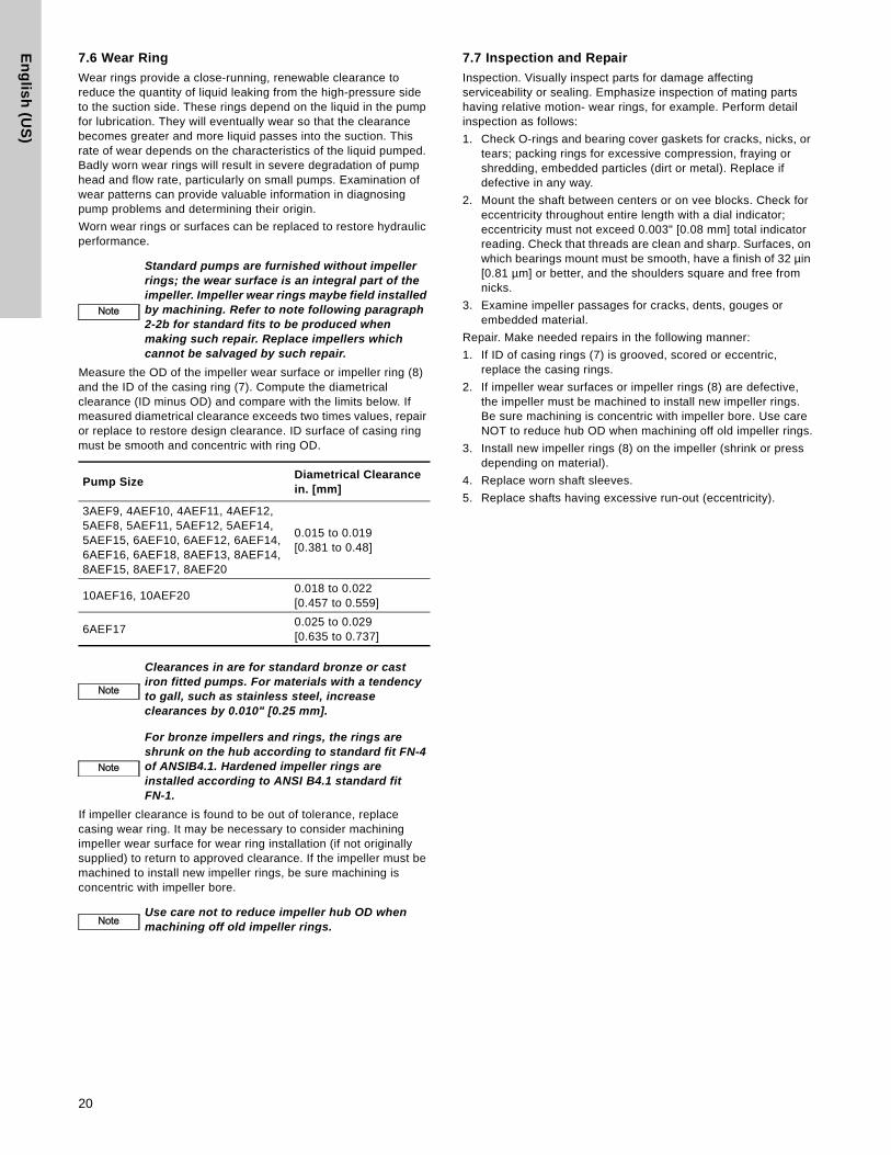
7.6 Wear Ring
Wear rings provide a close-running, renewable clearance to reduce the quantity of liquid leaking from the high-pressure side to the suction side. These rings depend on the liquid in the pump for lubrication. They will eventually wear so that the clearance becomes greater and more liquid passes into the suction. This rate of wear depends on the characteristics of the liquid pumped. Badly worn wear rings will result in severe degradation of pump head and flow rate, particularly on small pumps. Examination of wear patterns can provide valuable information in diagnosing pump problems and determining their origin.
Worn wear rings or surfaces can be replaced to restore hydraulic performance.
Measure the OD of the impeller wear surface or impeller ring (8) and the ID of the casing ring (7). Compute the diametrical clearance (ID minus OD) and compare with the limits below. If measured diametrical clearance exceeds two times values, repair or replace to restore design clearance. ID surface of casing ring must be smooth and concentric with ring OD.
If impeller clearance is found to be out of tolerance, replace casing wear ring. It may be necessary to consider machining impeller wear surface for wear ring installation (if not originally supplied) to return to approved clearance. If the impeller must be machined to install new impeller rings, be sure machining is concentric with impeller bore.
7.7 Inspection and Repair
Inspection. Visually inspect parts for damage affecting serviceability or sealing. Emphasize inspection of mating parts having relative motion- wear rings, for example. Perform detail inspection as follows:
1. Check O-rings and bearing cover gaskets for cracks, nicks, or tears; packing rings for excessive compression, fraying or shredding, embedded particles (dirt or metal). Replace if defective in any way.
2. Mount the shaft between centers or on vee blocks. Check for eccentricity throughout entire length with a dial indicator; eccentricity must not exceed 0.003" [0.08 mm] total indicator reading. Check that threads are clean and sharp. Surfaces, on which bearings mount must be smooth, have a finish of 32 µin [0.81 µm] or better, and the shoulders square and free from nicks.
3. Examine impeller passages for cracks, dents, gouges or embedded material.
Repair. Make needed repairs in the following manner:
1. If ID of casing rings (7) is grooved, scored or eccentric, replace the casing rings.
2. If impeller wear surfaces or impeller rings (8) are defective, the impeller must be machined to install new impeller rings. Be sure machining is concentric with impeller bore. Use care NOT to reduce hub OD when machining off old impeller rings.
3. Install new impeller rings (8) on the impeller (shrink or press depending on material).
4. Replace worn shaft sleeves.
5. Replace shafts having excessive run-out (eccentricity).
NoteNote
Standard pumps are furnished without impeller rings; the wear surface is an integral part of the impeller. Impeller wear rings maybe field installed by machining. Refer to note following paragraph 2-2b for standard fits to be produced when making such repair. Replace impellers which cannot be salvaged by such repair.
Pump SizeDiametrical Clearance in. [mm]
3AEF9, 4AEF10, 4AEF11, 4AEF12, 5AEF8, 5AEF11, 5AEF12, 5AEF14, 5AEF15, 6AEF10, 6AEF12, 6AEF14, 6AEF16, 6AEF18, 8AEF13, 8AEF14, 8AEF15, 8AEF17, 8AEF20
0.015 to 0.019[0.381 to 0.48]
10AEF16, 10AEF200.018 to 0.022 [0.457 to 0.559]
6AEF170.025 to 0.029[0.635 to 0.737]
NoteNote
Clearances in are for standard bronze or cast iron fitted pumps. For materials with a tendency to gall, such as stainless steel, increase clearances by 0.010" [0.25 mm].
NoteNote
For bronze impellers and rings, the rings are shrunk on the hub according to standard fit FN-4 of ANSIB4.1. Hardened impeller rings are installed according to ANSI B4.1 standard fit FN-1.
NoteNoteUse care not to reduce impeller hub OD when machining off old impeller rings.
20
En
gli
sh
(U
S)
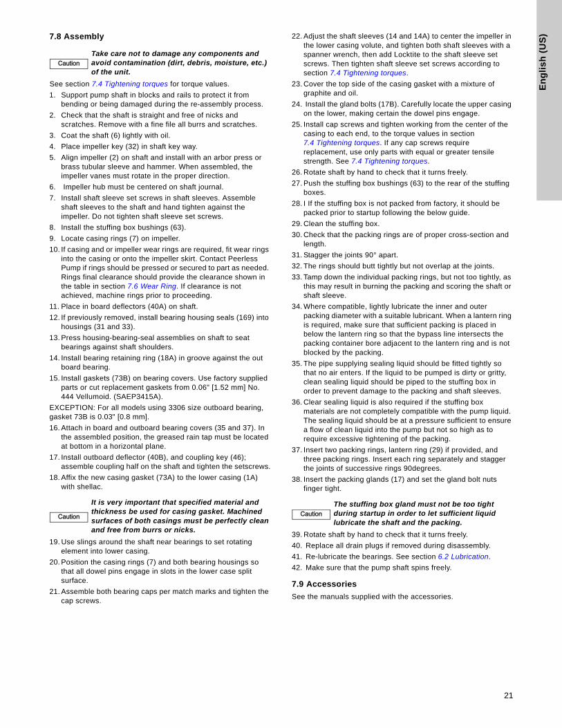
7.8 AssemblySee section 7.4 Tightening torques for torque values.
1. Support pump shaft in blocks and rails to protect it from bending or being damaged during the re-assembly process.
2. Check that the shaft is straight and free of nicks and scratches. Remove with a fine file all burrs and scratches.
3. Coat the shaft (6) lightly with oil.
4. Place impeller key (32) in shaft key way.
5. Align impeller (2) on shaft and install with an arbor press or brass tubular sleeve and hammer. When assembled, the impeller vanes must rotate in the proper direction.
6. Impeller hub must be centered on shaft journal.
7. Install shaft sleeve set screws in shaft sleeves. Assemble shaft sleeves to the shaft and hand tighten against the impeller. Do not tighten shaft sleeve set screws.
8. Install the stuffing box bushings (63).
9. Locate casing rings (7) on impeller.
10. If casing and or impeller wear rings are required, fit wear rings into the casing or onto the impeller skirt. Contact Peerless Pump if rings should be pressed or secured to part as needed. Rings final clearance should provide the clearance shown in the table in section 7.6 Wear Ring. If clearance is not achieved, machine rings prior to proceeding.
11. Place in board deflectors (40A) on shaft.
12. If previously removed, install bearing housing seals (169) into housings (31 and 33).
13. Press housing-bearing-seal assemblies on shaft to seat bearings against shaft shoulders.
14. Install bearing retaining ring (18A) in groove against the out board bearing.
15. Install gaskets (73B) on bearing covers. Use factory supplied parts or cut replacement gaskets from 0.06" [1.52 mm] No. 444 Vellumoid. (SAEP3415A).
EXCEPTION: For all models using 3306 size outboard bearing, gasket 73B is 0.03" [0.8 mm].
16. Attach in board and outboard bearing covers (35 and 37). In the assembled position, the greased rain tap must be located at bottom in a horizontal plane.
17. Install outboard deflector (40B), and coupling key (46); assemble coupling half on the shaft and tighten the setscrews.
18. Affix the new casing gasket (73A) to the lower casing (1A) with shellac.
19. Use slings around the shaft near bearings to set rotating element into lower casing.
20. Position the casing rings (7) and both bearing housings so that all dowel pins engage in slots in the lower case split surface.
21. Assemble both bearing caps per match marks and tighten the cap screws.
22. Adjust the shaft sleeves (14 and 14A) to center the impeller in the lower casing volute, and tighten both shaft sleeves with a spanner wrench, then add Locktite to the shaft sleeve set screws. Then tighten shaft sleeve set screws according to section 7.4 Tightening torques.
23. Cover the top side of the casing gasket with a mixture of graphite and oil.
24. Install the gland bolts (17B). Carefully locate the upper casing on the lower, making certain the dowel pins engage.
25. Install cap screws and tighten working from the center of the casing to each end, to the torque values in section 7.4 Tightening torques. If any cap screws require replacement, use only parts with equal or greater tensile strength. See 7.4 Tightening torques.
26. Rotate shaft by hand to check that it turns freely.
27. Push the stuffing box bushings (63) to the rear of the stuffing boxes.
28. I If the stuffing box is not packed from factory, it should be packed prior to startup following the below guide.
29. Clean the stuffing box.
30. Check that the packing rings are of proper cross-section and length.
31. Stagger the joints 90° apart.
32. The rings should butt tightly but not overlap at the joints.
33. Tamp down the individual packing rings, but not too tightly, as this may result in burning the packing and scoring the shaft or shaft sleeve.
34. Where compatible, lightly lubricate the inner and outer packing diameter with a suitable lubricant. When a lantern ring is required, make sure that sufficient packing is placed in below the lantern ring so that the bypass line intersects the packing container bore adjacent to the lantern ring and is not blocked by the packing.
35. The pipe supplying sealing liquid should be fitted tightly so that no air enters. If the liquid to be pumped is dirty or gritty, clean sealing liquid should be piped to the stuffing box in order to prevent damage to the packing and shaft sleeves.
36. Clear sealing liquid is also required if the stuffing box materials are not completely compatible with the pump liquid. The sealing liquid should be at a pressure sufficient to ensure a flow of clean liquid into the pump but not so high as to require excessive tightening of the packing.
37. Insert two packing rings, lantern ring (29) if provided, and three packing rings. Insert each ring separately and stagger the joints of successive rings 90degrees.
38. Insert the packing glands (17) and set the gland bolt nuts finger tight.
39. Rotate shaft by hand to check that it turns freely.
40. Replace all drain plugs if removed during disassembly.
41. Re-lubricate the bearings. See section 6.2 Lubrication.
42. Make sure that the pump shaft spins freely.
7.9 Accessories
See the manuals supplied with the accessories.
CautionTake care not to damage any components and avoid contamination (dirt, debris, moisture, etc.) of the unit.
Caution
It is very important that specified material and thickness be used for casing gasket. Machined surfaces of both casings must be perfectly clean and free from burrs or nicks.
CautionThe stuffing box gland must not be too tight during startup in order to let sufficient liquid lubricate the shaft and the packing.
21

En
glis
h (U
S)
8. Fault finding (Trouble Shooting)
NoteNoteWhen direct-connected to electric motors, determine whether or not the motor is direct-on-line and receives full voltage.
Fault Cause Remedy
1. Discharge pressure too low. a) Speed too low. Check speed/rotation.
b) System pressure lower than anticipated. Check the system curve.
c) Air or gas in liquid. Check liquid to remove air.
d) Worn wear rings. Check clearance between wear surfaces.
e) Impeller damaged. Check that parts are not damaged.
f) Impeller diameter too small. Check specified diameter.
g) Wrong direction of rotation. Check rotation.
h) Pump lost prime. Re-prime pump.
i) Insufficient available NPSH. Confirm NPSH available.
j) Restricted passages. Clean impeller and casing passages.
k) Leaking joints. • Tighten joints.• Tighten packing.• Check o-ring between sleeve and shaft.• Check gaskets.
2. Insufficient suction head. a) Suction line drawing air. Tighten line connections.
b) Suction lift too high or insufficient NPSH. Check NPSHA.
c) Air or gas in liquid. Remove air/gas from liquid.
d) Clogged strainer. Clean the strainer.
3. Noise level increased. a) Poor alignment of pump. Suction and discharge pipe clamps loose.
• Ensure proper alignment of the pump and the driver.
• Support the suction and discharge piping. • Check vibration dampers, flexible piping and
conduit connectors.
b) Cracked foundation. Check foundation.
c) Worn ball bearings. • Check bearings.• Check lubrication.
d) Driver unbalanced. Disconnect driver and operate it alone. Check pump for large pieces of debris, such as wood, rags, etc.
e) Hydraulic resonance. • Alter the resonant piping. • Change the pump speed. • Insert a pulsation damper on the pump/
piping system. • Insert flow straighteners.
4. Insufficient flow. a) Pump not primed. Check suction conditions.
b) System head exceeds shut off head. Check system head curve vs. performance curve.
c) Speed too low. Check rotation speed.
d) Suction lift too high or insufficient NPSH. Check NPSHA.
e) Clogged strainer or impeller. Clean the strainer and impeller passages.
f) Wrong direction of rotation. Check rotation.
g) Leaking joints. Tighten joints.
h) Broken shafting or coupling Rotate shaft and inspect.
i) Closed suction valve. Check suction valve.
j) Not enough suction head for hot or volatile liquids.
Check NPSHA.
k) Foot valve too small; Check foot valve.
l) Worn or damaged hydraulic parts. Inspect part.
m) Excessive clearance between wear surfaces.
See section 7.6 Wear Ring for ring clearance.
22

En
gli
sh
(U
S)
5. Pump loses prime after starting. a) Leaking joints. • Tighten joints.• Tighten packing.• Check o-ring between sleeve and shaft.• Check gaskets.
b) Suction lift too high or insufficient NPSH. Check NPSHA.
6. Excessive power required. a) Speed too high. Check rotation speed.
b) Pump operating outside of the allowable operating region (AOR).
• Check system curve.• Check valve settings.
c) Specific gravity or viscosity of liquid pumped is too high.
Check predicted performance based on liquid conditions.
d) Bent shaft or rotating element. Check parts and straighten as needed.
e) Stuffing-boxes too tight. Check drip rate of liquid from packing.
f) Impeller clearance too small causing rubbing or worn wear surfaces.
Check clearance between wear surfaces.
g) Electrical or mechanical defect in motor Contact local service center for diagnostics.
h) Restriction in rotation. Check for binding of rotating elements.
i) Incorrect lubrication of driver. Check lubrication type and amount.
Fault Cause Remedy
23

En
glis
h (U
S)
9. Parts list and sectional drawing
Fig. 9 Packed Type Cross Sectional Drawing
TM
06
09
79
13
14
Item No. Description Item No. Description
1A, 1B, 41, 43 Upper and Lower Casings 31 Inboard Bearing Housing
2 Impeller 32 Impeller Key
6 Shaft 33 Outboard Bearing Housing
7 Casing Ring 35 Inb. Brg. Housing Cover
8 Impeller Ring (Optional) 37 Out. Brg. Housing Cover
13 Packing Ring 40A Inboard Deflector
14, 14A Shaft SleeveRHLH
40B Outboard Deflector
14B Shaft Sleeve "O" Ring 46 Coupling Key
16 Inboard Ball Bearing 47 Inb. Brg. Cover Seal
17 Packing Gland 63 Stuffing Box Bushing
17A Gland Clip (when used) 73A Casing Gasket (Not Shown)
17B Gland Bolt 73B Bearing Cover Gasket
18 Outboard Ball Bearing 123 Bearing End Cover
18A Bearing Lock Washer 127 Water Seal Piping
29 Lantern Ring (Op tional) 169 Bearing Housing Seal
- Casing Hardware
24
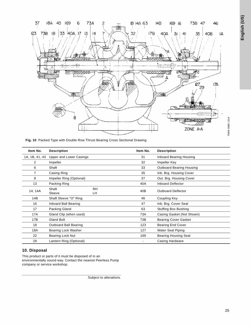
En
gli
sh
(U
S)
Fig. 10 Packed Type with Double Row Thrust Bearing Cross Sectional Drawing
10. DisposalThis product or parts of it must be disposed of in an environmentally sound way. Contact the nearest Peerless Pump company or service workshop.
Subject to alterations.
TM
06
09
80
13
14
Item No. Description Item No. Description
1A, 1B, 41, 43 Upper and Lower Casings 31 Inboard Bearing Housing
2 Impeller 32 Impeller Key
6 Shaft 33 Outboard Bearing Housing
7 Casing Ring 35 Inb. Brg. Housing Cover
8 Impeller Ring (Optional) 37 Out. Brg. Housing Cover
13 Packing Ring 40A Inboard Deflector
14, 14AShaftSleeve
RHLH
40B Outboard Deflector
14B Shaft Sleeve "O" Ring 46 Coupling Key
16 Inboard Ball Bearing 47 Inb. Brg. Cover Seal
17 Packing Gland 63 Stuffing Box Bushing
17A Gland Clip (when used) 73A Casing Gasket (Not Shown)
17B Gland Bolt 73B Bearing Cover Gasket
18 Outboard Ball Bearing 123 Bearing End Cover
18A Bearing Lock Washer 127 Water Seal Piping
22 Bearing Lock Nut 169 Bearing Housing Seal
29 Lantern Ring (Optional) - Casing Hardware
25

26

Pe
erl
es
s P
um
p c
om
pa
nie
sPeerless Pump Indianapolis2005 Dr. Martin Luther King Jr
US-46202 Indianapolis, Indiana U.S.A.
Phone: (+1) 317.925.9661
www.peerlesspump.com

Reliability When It Matters
98692495 0514
ECM: 1137721
m