Embed Size (px)
Citation preview

Insulated drain pan • Galvanized or Stainless Steel• Optional secondary overflow drain connection
Optional filter rack with hinged doors and latch. Available on side and bottom for ducted inlet application.
Hinged door control enclosure will accept a toggle disconnect or a door interlocking type and can accommodate controls for BAS Communications.
Comprehensive liner options • 3/4" (19) or 1" (25) D.D. fiberglass • Steri-liner (foil faced) • Fiber-free (closed cell foam) • Perforated metal with insulation
Blower/Motor assembly; isolated from fan housing
• 3-speed PSC • Multi-speed ECM • EPIC ECM
Multiple coil options:
• 3, 4, 5, 6 row cooling or heating coils
• 1 or 2 row preheat or reheat coil
Coil enclosure with fiber-free –
foam insulation for increased thermal efficiency.
Removable electric heater rack, easily accessible within a hinged cabinet enclosure
18 ga. (1.31) galvanized formed steel frame
Filter • 1" (25) throwaway
(standard) • 2" (51) MERV 8 or
MERV 13 pleated (optional)
Secondary drain outlet
Primary drain outlet
Model Series 35FH • Direct Drive Draw-through Design
HO
RIZ
ON
TAL FA
N C
OIL U
NITS •
DU
CTED
B
HORIZONTAL HIGH CAPACITY FAN COIL UNITS • DUCTED
B2
9-4-19
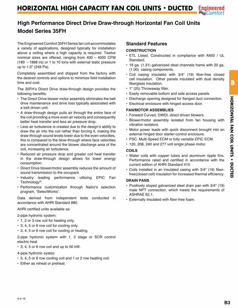
High Performance Direct Drive Draw-through Horizontal Fan Coil UnitsModel Series 35FH
The Engineered Comfort 35FH Series fan coil accommodates a variety of applications, designed typically for installation above a ceiling where a high capacity is required. Twelve nominal sizes are offered, ranging from 400 – 4000 CFM (189 – 1888 l/s) or 1 to 10 tons with external static pressure up to 1.0" (249 Pa).
Completely assembled and shipped from the factory with the desired controls and options to minimize field installation time and cost.
The 35FH’s Direct Drive draw-through design provides the following benefits:• The Direct Drive blower motor assembly eliminates the belt
drive maintenance and drive loss typically associated witha belt driven unit.
• A draw-through design pulls air through the entire face ofthe coil providing a more even air velocity and consequently better heat transfer and less air pressure drop.
• Less air turbulence is created due to the design’s ability todraw the air into the coil rather than forcing it, making thedraw-through sound levels lower due to the even velocities,this is compared to the blow-through where face velocitiesare concentrated around the blower discharge area of thecoil, increasing air turbulence.
• Reduced air pressure drop and greater coil heat transferin the draw-through design allows for lower energyconsumption.
• Direct Drive blower/motor assembly reduces the amount ofsound transmission to the occupant.
• Industry leading performance utilizing EPIC FanTechnology®.
• Performance customization through Nailor's selectionprogram, 'SelectWorks'.
Data derived from independent tests conducted in accordance with AHRI Standard 880.
AHRI certified units available as:
2-pipe hydronic system:• 1, 2 or 3 row coil for heating only.• 3, 4, 5 or 6 row coil for cooling only.• 3, 4, 5 or 6 row coil for cooling or heating.
2-pipe hydronic system with 1, 2 stage or SCR controlelectric heat• 3, 4, 5 or 6 row coil and up to 50 kW.
4-pipe hydronic systes:• 3, 4, 5 or 6 row cooling coil and 1 or 2 row heating coil.• Either as reheat or preheat.
Standard FeaturesCONSTRUCTION• ETL Listed. Constructed in compliance with ANSI / UL
Standard.• 18 ga. (1.31) galvanized steel channels frame with 20 ga.
(1.00) casing components.• Coil casing insulated with 3/4" (19) fiber-free closed
cell insulation. Other panels insulated with dual densityfiberglass insulation.
• 1" (25) Throwaway filter.• Easily removable bottom and side access panels.• Discharge opening designed for flanged duct connection.• Electrical enclosure with hinged access door.
FAN/MOTOR ASSEMBLIES• Forward Curved, DWDI, direct driven blowers.• Blower/motor assembly isolated from fan housing with
vibration isolators.• Motor power leads with quick disconnect brought into an
external hinged door starter-control enclosure.• PSC, Multi-Speed ECM or fully variable EPIC ECM.• 120, 208, 240 and 277 volt single phase motor.
COILS• Water coils with copper tubes and aluminum ripple fins.
Performance rated and certified in accordance with thecurrent edition of AHRI Standard 410.
• Coils installed in an insulated casing with 3/4" (19) fiber-free(closed cell) insulation for increased thermal efficiency.
DRAIN PANS• Positively sloped galvanized steel drain pan with 3/4" (19)
male NPT connection, which meets the requirements ofASHRAE 62.1.
• Externally insulated with fiber-free foam.
HO
RIZ
ON
TAL FA
N C
OIL U
NITS •
DU
CTED
B
HORIZONTAL HIGH CAPACITY FAN COIL UNITS • DUCTED
B3
9-9-19
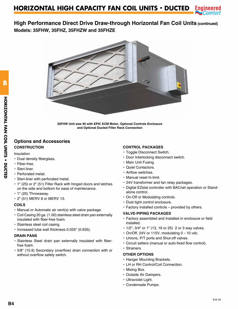
High Performance Direct Drive Draw-through Horizontal Fan Coil Units (continued)
Models: 35FHW, 35FHZ, 35FHZW and 35FHZE
Options and AccessoriesCONSTRUCTION
Insulation• Dual density fiberglass.• Fiber-free.• Steri-liner.• Perforated metal.• Steri-liner with perforated metal.• 1" (25) or 2" (51) Filter Rack with hinged doors and latches
on the side and bottom for ease of maintenance. • 1" (25) Throwaway.• 2" (51) MERV 8 or MERV 13.
COILS• Manual or Automatic air vent(s) with valve package. • Coil Casing 20 ga. (1.00) stainless steel drain pan externally
insulated with fiber-free foam.• Stainless steel coil casing.• Increased tube wall thickness 0.025" (0.635).
DRAIN PANS• Stainless Steel drain pan externally insulated with fiber-
free foam.• 5/8" (15.9) Secondary (overflow) drain connection with or
without overflow safety switch.
CONTROL PACKAGES• Toggle Disconnect Switch.• Door Interlocking disconnect switch.• Main Unit Fusing.• Quiet Contactors.• Airflow switches.• Manual reset hi-limit.• 24V transformer and fan relay packages.• Digital EZstat controller with BACnet operation or Stand-
alone control.• On-Off or Modulating controls.• Dust tight control enclosure.• Factory installed controls – provided by others.
VALVE-PIPING PACKAGES• Factory assembled and Installed in enclosure or field
installed.• 1/2", 3/4" or 1" (13, 19 or 25) 2 or 3 way valves. • On/Off, 24V or 115V, modulating 0 – 10 vdc.• Unions, P/T ports and Shut-off valves.• Circuit setters (manual or auto-fixed flow control).• Strainers.
OTHER OPTIONS• Hanger Mounting Brackets.• LH or RH Control/Coil Connection.• Mixing Box.• Outside Air Dampers.• Ultraviolet Light.• Condensate Pumps.
35FHW Unit size 40 with EPIC ECM Motor, Optional Controls Enclosure and Optional Ducted Filter Rack Connection
HO
RIZ
ON
TAL FA
N C
OIL U
NITS •
DU
CTED
B
HORIZONTAL HIGH CAPACITY FAN COIL UNITS • DUCTED
B4
F 23" (584)1" (25) IH
2 1/2" (64)
WATERCOIL
SECTION
AIRFLOW
DH1" (25)
14" (356)
E W
B
DWIW
PRIMARY DRAIN CONNECTIONOPTIONAL SECONDARY DRAIN CONNECTION
COOLING ORPREHEAT COILCONNECTIONS
REHEAT COILOR COOLING
CONNECTIONS
17"(432)
5 3/4"(146)
16" (406)
LINEVOLTAGE
CONTROLSENCLOSURE
OPTIONALFILTER
FAN
14"(356)
OPTIONALVALVE
ENCLOSURE
VALVEACCESS
DOOR
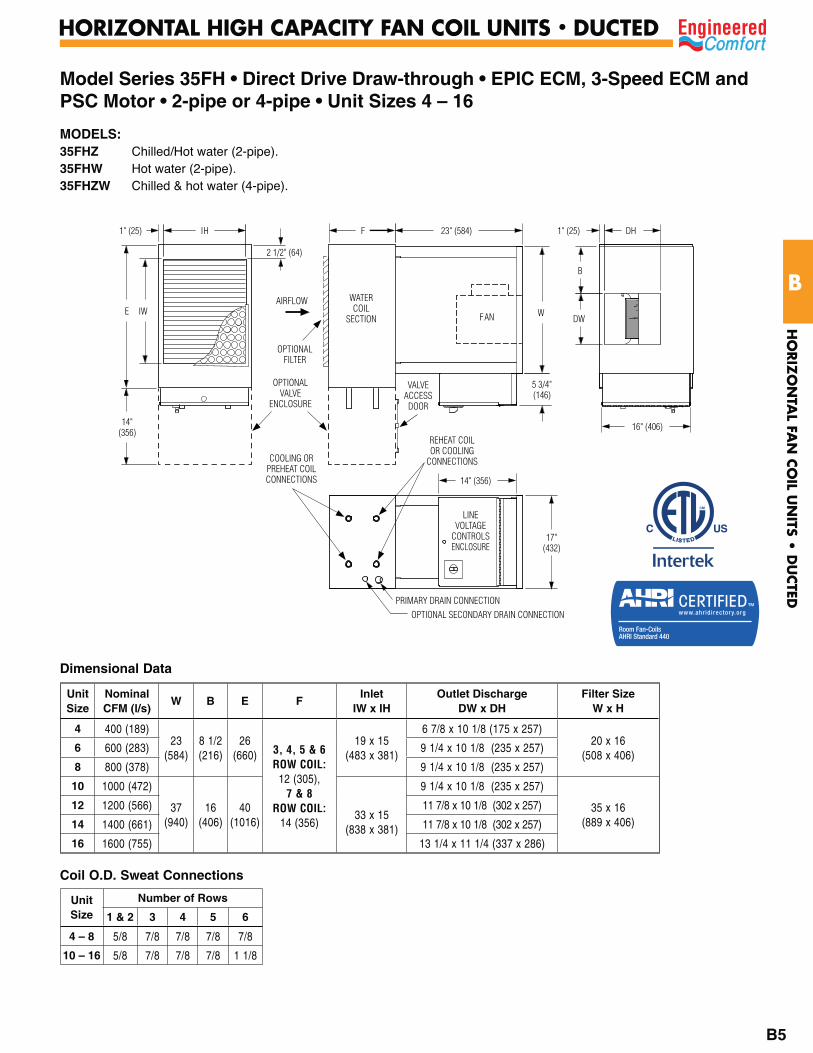
Model Series 35FH • Direct Drive Draw-through • EPIC ECM, 3-Speed ECM and PSC Motor • 2-pipe or 4-pipe • Unit Sizes 4 – 16
Dimensional Data
Coil O.D. Sweat Connections
MODELS:35FHZ Chilled/Hot water (2-pipe).35FHW Hot water (2-pipe).35FHZW Chilled & hot water (4-pipe).
Unit Size
NominalCFM (l/s)
W B E FInlet
IW x IHOutlet Discharge
DW x DHFilter Size
W x H
4 400 (189)23
(584)8 1/2(216)
26(660) 3, 4, 5 & 6
ROW COIL:12 (305),
7 & 8ROW COIL:
14 (356)
19 x 15(483 x 381)
6 7/8 x 10 1/8 (175 x 257)20 x 16
(508 x 406)6 600 (283) 9 1/4 x 10 1/8 (235 x 257)
8 800 (378) 9 1/4 x 10 1/8 (235 x 257)
10 1000 (472)
37(940)
16(406)
40(1016)
33 x 15(838 x 381)
9 1/4 x 10 1/8 (235 x 257)
35 x 16 (889 x 406)
12 1200 (566) 11 7/8 x 10 1/8 (302 x 257)
14 1400 (661) 11 7/8 x 10 1/8 (302 x 257)
16 1600 (755) 13 1/4 x 11 1/4 (337 x 286)
Unit Size
Number of Rows
1 & 2 3 4 5 6
4 – 8 5/8 7/8 7/8 7/8 7/8
10 – 16 5/8 7/8 7/8 7/8 1 1/8
HO
RIZ
ON
TAL FA
N C
OIL U
NITS •
DU
CTED
B
HORIZONTAL HIGH CAPACITY FAN COIL UNITS • DUCTED
B5
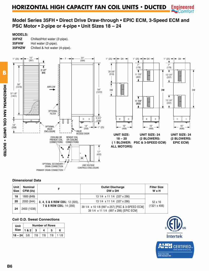
Model Series 35FH • Direct Drive Draw-through • EPIC ECM, 3-Speed ECM and PSC Motor • 2-pipe or 4-pipe • Unit Sizes 18 – 24
Dimensional Data
Coil O.D. Sweat Connections
DW
16"(406)
1" (25)
13 1/4"(337)
13 1/4"(337)
7"(178)
DH
AIRFLOW
OPTIONALFILTER
14"(356) 1" (25)
16"(406)
17"(432)
LINE VOLTAGECONTROLS ENCLOSURE
F15"(381)
23"(584)
54"(1372)
DH1" (25)1" (25)
2 1/2"(64)
50"(1270)
57 1/8"(1451)
20 3/8"(518)
DW DW
16"(406)
1" (25)
11 7/8"(302)
11 7/8"(302)
7"(178)
5 3/4"(146)
DH
OPTIONAL SECONDARYDRAIN CONNECTION
PRIMARY DRAIN CONNECTION
OPTIONALVALVE
ENCLOSURE VALVEACCESS DOOR
14"(356)
COOLING ORPREHEAT COILCONNECTIONS
REHEAT COILOR COOLING
CONNECTIONS
2 1/2"(64)
DW
11 7/8"(302)
UNIT SIZE:18 – 20
( 1 BLOWER:ALL MOTORS)
UNIT SIZE: 24(2 BLOWERS:
PSC & 3-SPEED ECM)
UNIT SIZE: 24(2 BLOWERS:
EPIC ECM)
MODELS:35FHZ Chilled/Hot water (2-pipe).35FHW Hot water (2-pipe).35FHZW Chilled & hot water (4-pipe).
Unit Size
NominalCFM (l/s)
FOutlet Discharge
DW x DHFilter Size
W x H
18 1800 (849)
3, 4, 5 & 6 ROW COIL: 12 (305),7 & 8 ROW COIL: 14 (356)
13 1/4 x 11 1/4 (337 x 286)
52 x 16 (1321 x 406)
20 2000 (944) 13 1/4 x 11 1/4 (337 x 286)
24 2400 (1038)39 1/4 x 10 1/8 (997 x 257) [PSC & 3-SPEED ECM]
39 1/4 x 11 1/4 (997 x 286) [EPIC ECM]
Unit Size
Number of Rows
1 & 2 3 4 5 6
18 – 24 5/8 7/8 7/8 7/8 1 1/8
HO
RIZ
ON
TAL FA
N C
OIL U
NITS •
DU
CTED
B
HORIZONTAL HIGH CAPACITY FAN COIL UNITS • DUCTED
B6

8-8-19
Model Series 35FH • Direct Drive Draw-through • EPIC ECM Motor • 2-pipe or 4-pipe • Unit Sizes 30 and 40
MODELS:35FHZ Chilled/Hot water (2-pipe).35FHW Hot water (2-pipe).35FHZW Chilled & hot water (4-pipe).
UNIT SIZES: 30 & 40
( 2 BLOWERS)
Dimensional Data
Unit Size
NominalCFM (l/s)
W E G BInlet
IW x IHOutlet Discharge
DW x DHFilter Size
W x H
30 3000 (1416) 54 (1372) 57 (1448) 2 3/8 (60) 7 (178) 50 x 20(1270 x 508)
39 1/4 x 12 1/2 (997 x 318)
52 x 22 (1321 x 559
40 4000 (1888) 64 (1626) 67 5/8 (1718) 2 7/8 (73) 8 5/16 (211)
60 x 20 (1524 x 508)
46 3/8 x 12 1/2(1178 x 318)
62 x 22 (1575 x 559)
Coil O.D. Sweat Connections
Unit Size
Number of Rows1 & 2 3 4 5 6
30 & 40 7/8 1 3/8 1 3/8 1 3/8 1 3/8
W
36" (914)
B
IH
G
1.5" (38)
E IW
23"(584)
DWAIRFLOW
FILTER
14" (356) 22" (559)
LINEVOLTAGE
CONTROLSENCLOSURE
1 5/8" (41) DH
OPTIONAL SECONDARYDRAIN CONNECTION
PRIMARY DRAIN CONNECTION
1"(25)
5 3/4"(146)
COOLING ORPREHEAT COILCONNECTIONS
14" (356)
REHEAT COILOR COOLINGCONNECTIONS
HO
RIZ
ON
TAL FA
N C
OIL U
NITS •
DU
CTED
B
HORIZONTAL HIGH CAPACITY FAN COIL UNITS • DUCTED
B7
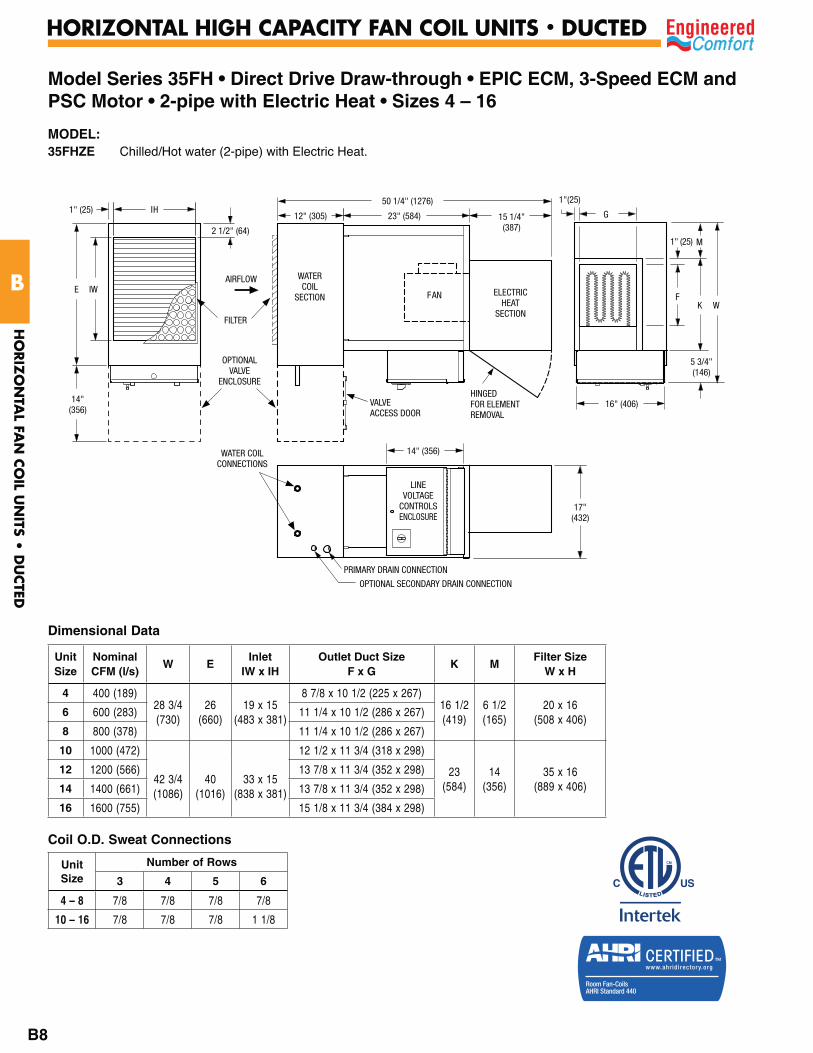
Model Series 35FH • Direct Drive Draw-through • EPIC ECM, 3-Speed ECM and PSC Motor • 2-pipe with Electric Heat • Sizes 4 – 16
Dimensional Data
Coil O.D. Sweat Connections
12" (305) 23" (584)
50 1/4" (1276)1" (25) IH
2 1/2" (64)
WATERCOIL
SECTION
AIRFLOW
G
1"(25)
1" (25)
14" (356)
E
W
M
KF
IW
PRIMARY DRAIN CONNECTION
OPTIONAL SECONDARY DRAIN CONNECTION
17"(432)
5 3/4"(146)
16" (406)
LINEVOLTAGE
CONTROLSENCLOSURE
FILTER
FAN
14"(356)
OPTIONALVALVE
ENCLOSURE
VALVEACCESS DOOR
15 1/4"(387)
HINGEDFOR ELEMENTREMOVAL
ELECTRICHEAT
SECTION
WATER COILCONNECTIONS
Unit Size
Number of Rows
3 4 5 6
4 – 8 7/8 7/8 7/8 7/8
10 – 16 7/8 7/8 7/8 1 1/8
MODEL:35FHZE Chilled/Hot water (2-pipe) with Electric Heat.
Unit Size
NominalCFM (l/s)
W EInlet
IW x IHOutlet Duct Size
F x GK M
Filter Size W x H
4 400 (189)28 3/4(730)
26(660)
19 x 15(483 x 381)
8 7/8 x 10 1/2 (225 x 267)16 1/2 (419)
6 1/2 (165)
20 x 16 (508 x 406)
6 600 (283) 11 1/4 x 10 1/2 (286 x 267)
8 800 (378) 11 1/4 x 10 1/2 (286 x 267)
10 1000 (472)
42 3/4(1086)
40(1016)
33 x 15(838 x 381)
12 1/2 x 11 3/4 (318 x 298)
23(584)
14 (356)
35 x 16 (889 x 406)
12 1200 (566) 13 7/8 x 11 3/4 (352 x 298)
14 1400 (661) 13 7/8 x 11 3/4 (352 x 298)
16 1600 (755) 15 1/8 x 11 3/4 (384 x 298)H
ORIZ
ON
TAL FA
N C
OIL U
NITS •
DU
CTED
B
HORIZONTAL HIGH CAPACITY FAN COIL UNITS • DUCTED
B8
AIRFLOW
FILTER
14"(356)
1" (25) 16"(406)
16"(406)
17"(432)
LINE VOLTAGECONTROLS ENCLOSURE
15"(381)
23"(584)
1" (25)
2 1/2"(64)
50"(1270)
57 1/8"(1451)
OPTIONALVALVE
ENCLOSURE VALVEACCESS DOOR
14"(356)
FAN
ELECTRICHEAT
SECTIONSIZE 20
(SIZE 24INCLUDES
SHADED AREA)
(SIZE 24, 2 BLOWERS)
50 1/4" (1276)15 1/4"(387)
WATERCOIL
SECTION
G
1"(25)
M
KF
5 3/4"(146)
5 3/4"(146)
59 3/4"(1518)
59 3/4"(1518)
G1" (25)
1" (25)1" (25)
M
KF
PRIMARY DRAIN CONNECTIONOPTIONAL SECONDARY DRAIN CONNECTION
WATER COILCONNECTIONS
12"(305)
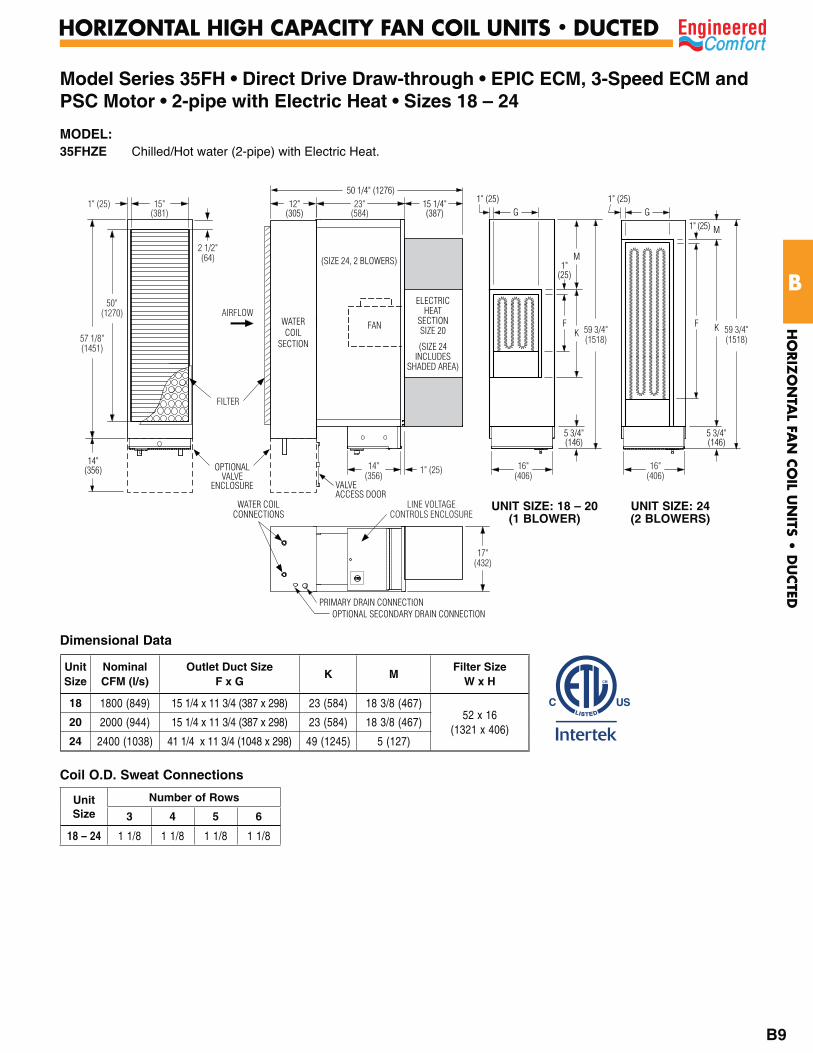
Model Series 35FH • Direct Drive Draw-through • EPIC ECM, 3-Speed ECM and PSC Motor • 2-pipe with Electric Heat • Sizes 18 – 24
UNIT SIZE: 18 – 20(1 BLOWER)
UNIT SIZE: 24(2 BLOWERS)
Dimensional Data
Coil O.D. Sweat Connections
Unit Size
Number of Rows
3 4 5 6
18 – 24 1 1/8 1 1/8 1 1/8 1 1/8
MODEL:35FHZE Chilled/Hot water (2-pipe) with Electric Heat.
Unit Size
NominalCFM (l/s)
Outlet Duct Size F x G
K MFilter Size
W x H
18 1800 (849) 15 1/4 x 11 3/4 (387 x 298) 23 (584) 18 3/8 (467)52 x 16
(1321 x 406)20 2000 (944) 15 1/4 x 11 3/4 (387 x 298) 23 (584) 18 3/8 (467)
24 2400 (1038) 41 1/4 x 11 3/4 (1048 x 298) 49 (1245) 5 (127)
HO
RIZ
ON
TAL FA
N C
OIL U
NITS •
DU
CTED
B
HORIZONTAL HIGH CAPACITY FAN COIL UNITS • DUCTED
B9

Model Series 35FH • Direct Drive Draw-through • EPIC ECM, 3-Speed ECM and PSC Motor • 2-pipe with Electric Heat • Sizes 30 and 40
MODEL:35FHZE Chilled/Hot water (2-pipe) with Electric Heat.
36" (914)72" (1829)
22" (559)IH 1.5" (38)
E IW
23"(584)
7/8"(22)
AIRFLOW
FILTER
14" (356) 22" (559)
LINEVOLTAGE
CONTROLSENCLOSURE
1"(25)
ELECTRICHEAT
SECTION
14" (356) G1" (25)
5 3/4"(146)
1" (25) M
K WF
J
PRIMARY DRAIN CONNECTIONOPTIONAL SECONDARY DRAIN CONNECTION
HINGEDFOR ELEMENTREMOVAL
SUPPLY AND RETURNWATER CONNECTIONS
Dimensional Data
Coil O.D. Sweat Connections
Unit Size
NominalCFM (l/s)
E JInlet
IW x IHOutlet Duct Size
F x GK M W
Filter SizeW x H
30 3000(1416) 57 1/8 (1451)
2 3/8(60)
50 x 20(1270 x 508)
41 1/2 x 12 (1054 x 305)
49(1245)
5(127)
59 3/4(1518)
52 x 22 (1321 x 559
40 4000 (1888) 67 5/8 (1718)
2 7/8 (73)
60 x 20 (1524 x 508)
48 1/2 x 13 1/2 (1232 x 343)
57(1448)
7(178)
69 3/4(1772)
62 x 22 (1575 x 559)
Unit Size
Number of Rows3 4 5 6
30 & 40 1 3/8 1 3/8 1 3/8 1 3/8
8-2-19
HO
RIZ
ON
TAL FA
N C
OIL U
NITS •
DU
CTED
B
B10
HORIZONTAL HIGH CAPACITY FAN COIL UNITS • DUCTED
8-2-19
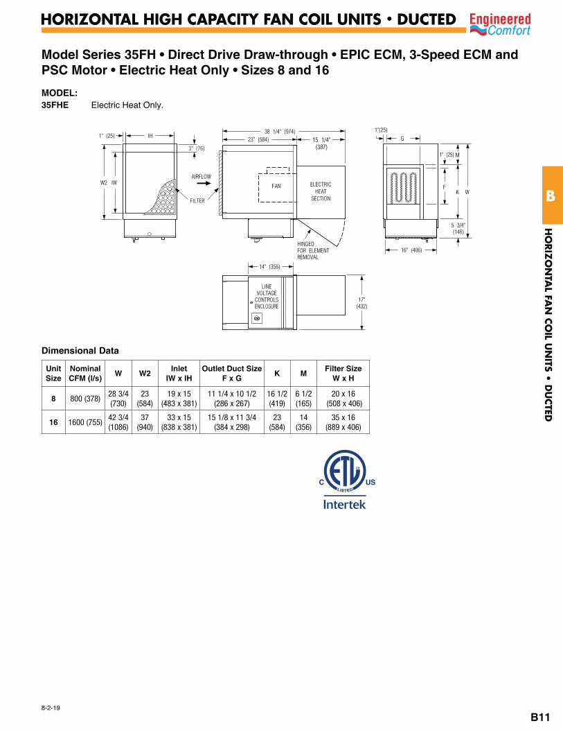
Model Series 35FH • Direct Drive Draw-through • EPIC ECM, 3-Speed ECM and PSC Motor • Electric Heat Only • Sizes 8 and 16
MODEL:35FHE Electric Heat Only.
23" (584)
38 1/4" (974)1" (25) IH
3" (76)
AIRFLOW
G
1"(25)
1" (25)
14" (356)
W2
W
M
KF
IW
17"(432)
5 3/4"(146)
16" (406)
LINEVOLTAGECONTROLSENCLOSURE
FAN
15 1/4"(387)
HINGEDFOR ELEMENTREMOVAL
ELECTRICHEAT
SECTIONFILTER
Unit Size
NominalCFM (l/s)
W W2Inlet
IW x IHOutlet Duct Size
F x GK M
Filter SizeW x H
8 800 (378)28 3/4(730)
23(584)
19 x 15(483 x 381)
11 1/4 x 10 1/2(286 x 267)
16 1/2 (419)
6 1/2 (165)
20 x 16 (508 x 406)
16 1600 (755)42 3/4(1086)
37(940)
33 x 15(838 x 381)
15 1/8 x 11 3/4(384 x 298)
23(584)
14 (356)
35 x 16(889 x 406)
Dimensional Data
HO
RIZ
ON
TAL FA
N C
OIL U
NITS •
DU
CTED
B
B11
HORIZONTAL HIGH CAPACITY FAN COIL UNITS • DUCTED
8-2-19
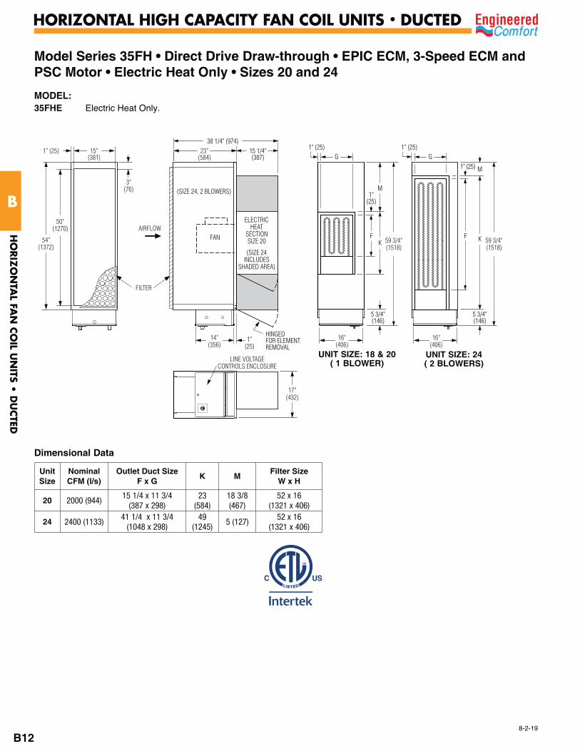
Model Series 35FH • Direct Drive Draw-through • EPIC ECM, 3-Speed ECM and PSC Motor • Electric Heat Only • Sizes 20 and 24
MODEL:35FHE Electric Heat Only.
UNIT SIZE: 18 & 20( 1 BLOWER)
UNIT SIZE: 24( 2 BLOWERS)
Unit Size
NominalCFM (l/s)
Outlet Duct Size F x G
K MFilter Size
W x H
20 2000 (944)15 1/4 x 11 3/4
(387 x 298)23
(584)18 3/8 (467)
52 x 16(1321 x 406)
24 2400 (1133)41 1/4 x 11 3/4
(1048 x 298)49
(1245)5 (127)
52 x 16(1321 x 406)
Dimensional Data
AIRFLOW
FILTER
14"(356)
16"(406)
16"(406)
17"(432)
LINE VOLTAGECONTROLS ENCLOSURE
15"(381)
23"(584)
1" (25)
3"(76)
50"(1270)
54"(1372)
FAN
ELECTRICHEAT
SECTIONSIZE 20
(SIZE 24INCLUDES
SHADED AREA)
(SIZE 24, 2 BLOWERS)
38 1/4" (974)15 1/4"(387) G
1"(25)
M
KF
5 3/4"(146)
5 3/4"(146)
59 3/4"(1518)
59 3/4"(1518)
G1" (25)
1" (25)1" (25)
M
KF
1"(25)
HINGEDFOR ELEMENTREMOVAL
HO
RIZ
ON
TAL FA
N C
OIL U
NITS •
DU
CTED
B
HORIZONTAL HIGH CAPACITY FAN COIL UNITS • DUCTED
B12
8-2-19
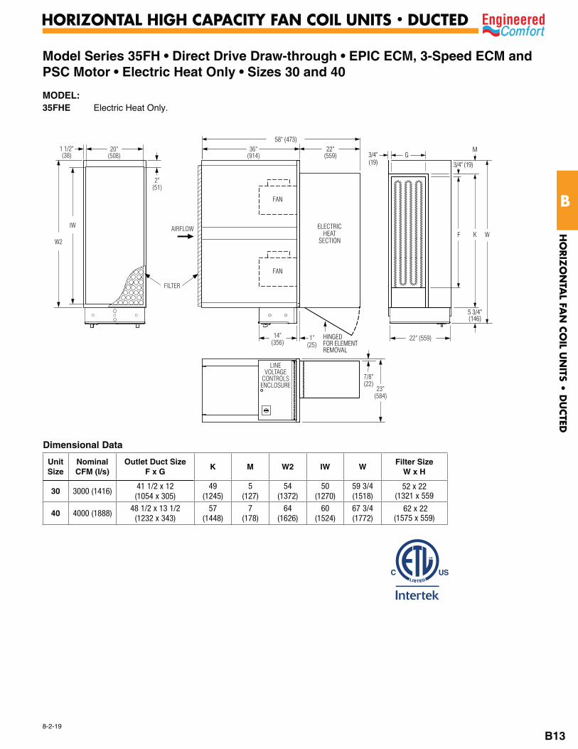
Model Series 35FH • Direct Drive Draw-through • EPIC ECM, 3-Speed ECM and PSC Motor • Electric Heat Only • Sizes 30 and 40
MODEL:35FHE Electric Heat Only.
Dimensional Data
Unit Size
NominalCFM (l/s)
Outlet Duct Size F x G
K M W2 IW WFilter Size
W x H
30 3000 (1416)41 1/2 x 12 (1054 x 305)
49 (1245)
5 (127)
54 (1372)
50 (1270)
59 3/4 (1518)
52 x 22 (1321 x 559
40 4000 (1888)48 1/2 x 13 1/2
(1232 x 343)57
(1448)7
(178)64
(1626)60
(1524)67 3/4 (1772)
62 x 22 (1575 x 559)
AIRFLOW
FILTER
14"(356)
1"(25)
7/8"(22)
22" (559)
23"(584)
LINEVOLTAGE
CONTROLSENCLOSURE
20"(508)
36"(914)
1 1/2"(38)
2"(51)
IW
W2
FAN
FAN
58" (473)22"
(559)
5 3/4"(146)
W
G3/4" (19)
M
KFELECTRIC
HEATSECTION
3/4"(19)
HINGEDFOR ELEMENTREMOVAL
HO
RIZ
ON
TAL FA
N C
OIL U
NITS •
DU
CTED
B
HORIZONTAL HIGH CAPACITY FAN COIL UNITS • DUCTED
B13

7-8-19
Model Series 35FH • Outside Air Inlet (OAI) OptionUnit Sizes 4 – 40
MODELS:35FHZ Chilled/Hot Water (2-pipe).35FHZW Chilled & Hot Water (4-pipe).35FHW Hot Water Only (2-pipe).35FHZE Chilled/Hot Water (2-pipe) with Electric Heat.
Dimensional Data
Unit Size
NominalCFM (l/s)
Available Outside Air Inlet (OAI) Dia.
W L
4 400 (189)
4, 5, 6 (102, 127, 152)
23 (584)
36(914)
6 600 (283) 23 (584)
8 800 (378) 23 (584)
10 1000 (472) 37 (940)
12 1200 (566) 4, 5, 6, 8 (102, 127, 152, 203)
37 (940)
14 1400 (661) 37 (940)
16 1600 (755)4, 5, 6, 8, 10
(102, 127, 152, 203, 254)
37 (940)
18 1800 (849) 54 (1372)
20 2000 (944) 54 (1372)
24 2400 (1038) 54 (1372)
30 3000 (1416) 4, 5, 6, 8, 10, 12 (102, 127, 152, 203,
254, 305)
54 (1372)
40 4000 (1888) 64 (1626)
Standard Construction (OAI Inlet):
1. Casing: 20 ga. (1.00), corrosion-resistant steel with stiffening beads.
2. Blade: Two layers of 20 ga. (1.00), corrosion-resistant steel laminated together with a cross-linked polyethylene peripheral gasket for tight shut-off. 90° rotation, CW to close. Damper leakage is less the 1% of the terminal rated airflow at 3" w.g. (750 pa.) and less than 2% at 6" w.g. (1500 pa.) as tested in accordance with ANSI / ASHRAE Standard 130.
3. Bearings: Self-lubricating oilite bronze.
4. Drive Shaft/Axles: 1/2" (13) diameter plated steel, double-bolted to blades. Indicator mark on the end of the shaft to show damper position.
5. Multi-point averaging Diamond Flow Sensor: Aluminum construction. Supplied with brass balancing tees. See EC-IOM-FCK for associated K-factor(s).
OPTIONS:• Full NEMA 1 type controls enclosure for field mounted
controllers/actuators.• Optional value enclosure for unit sizes 4 – 24.
WATERCOIL
SECTION
AIRFLOWW
5 3/4"(146)
FAN
OPTIONALVALVE ENCLOSURE
11 1/2"(292)
CL
VALVEACCESS DOOR
L
OPTIONAL AIR INLET (OAI)
OPTIONALCONTROLSENCLOSURE
9 3/4"(248)
3 7/8" (98)
FILTER
8 1/4"(210)
DIA. = NOM. - 1/8" (3)
15" (381)
HO
RIZ
ON
TAL FA
N C
OIL U
NITS •
DU
CTED
B
HORIZONTAL HIGH CAPACITY FAN COIL UNITS • DUCTED
B14

DESCRIPTION:• The FFR Ducted Return Filter Rack Connection is an
optional accessory for the Horizontal Fan Coil Units Model Series 35FH and 37FH.
• The accessory is required for ducted inlet applications where a filter is also required and ease of accessibility is required.
• The Ducted Filter Connection features a filter rack, which accommodates a 1" (25) standard or 2" (51) optional filter.
• Factory mounted on the induced air inlet of the draw-through water coil section.
• A piano-hinged door flap with latch on the side and bottom of the unit accessory allows for easy removal and replacement of the filter.
• The accessory is provided with a nominally sized duct connection collar.
• Side access to filter is same as coil hand.Dimensional Data
Unit Size
Inlet Size W x H
Filter SizeW x H
(Nominal)
4, 6, 8 16 1/2 x 20 1/4 (419 x 514) 20 x 16 (508 x 406)
10, 12, 14, 16 16 1/2 x 35 1/4 (419 x 895) 35 x 16 (889 x 406)
18, 20, 24 16 1/2 x 52 1/4 (419 x 1327) 52 x 16 (1321 x 406)
1"(25)
H
DOOR FLAPOPENING ONSIDE ANDBOTTOM
SIDE AND BOTTOMACCESS
LATCH
FILTERRACK
MOUNTINGFLANGE
AIRFLOW
5 1/2"(140)
W
Model Series 35FH • Filter Rack Option • Options and Accessories
3-13-18
HO
RIZ
ON
TAL FA
N C
OIL U
NITS •
DU
CTED
B
HORIZONTAL HIGH CAPACITY FAN COIL UNITS • DUCTED
B15

Model Series 35FH • Mixing Box • Options and Accessories
HINGED DOORFOR FILTERACCESS
H
WAB
B
A 23"(587)
MODEL: MBBRSIZE: 4 – 16
MODEL: MBTRSIZE: 4 – 16
MODEL: MBBRSIZE: 18 – 24
MODEL: MBTRSIZE: 18 – 24
B
HINGED DOORFOR FILTERACCESS
H
W
B
A
AB 23"
(587)
3 1/2" (89)TYP.
HINGEDDOORFORFILTERACCESS
H
W
AA
B 23"(587)
3 1/2" (89) TYP.
B
A + 3 1/4" (83)A
B +3 1/4" (83)
B
B
HINGEDDOORFORFILTERACCESS
H
W
A
23"(587)
4 1/2" (114)TYP.
MODELS:MBBR Bottom and Rear Return Dampers.MBTR Top and Rear Return Dampers.
Dimensional Data
STANDARD FEATURES:
• 18 ga. (1.31) galvanized steel casing.• 3/4" (19) dual density insulation, exposed edges coated to
prevent air erosion. Meets the requirements of NFPA 90A and UL 181.
• Low leakage parallel control dampers with blade and jamb seals.
• Filter rack to accommodate a 1" (25) standard or 2" (51)• A piano-hinged door flap with latch on the side and bottom
of the mixing box allows for easy removal and replacement of filter.
The fully insulated mixing box with filter rack and heavy duty dampers provides a mixing capability for control of return air and outside air for economizer operation.
Unit Size
A B W H
4, 6, 8 19 (483) 17 (432)
10, 12, 14, 16 33 (838) 17 (432
18, 20, 24 50 (1270) 17 (432
• 1 5/8" (41) flange on dampers for a flanged duct connection.• 1/2" (13) dia. driveshaft.• Crank-arms, swivels and linkage rod provided for damper
inter-connection.• Actuator and controls by others.• Assembly ships loose.
HO
RIZ
ON
TAL FA
N C
OIL U
NITS •
DU
CTED
B
HORIZONTAL HIGH CAPACITY FAN COIL UNITS • DUCTED
B16
1-14-20
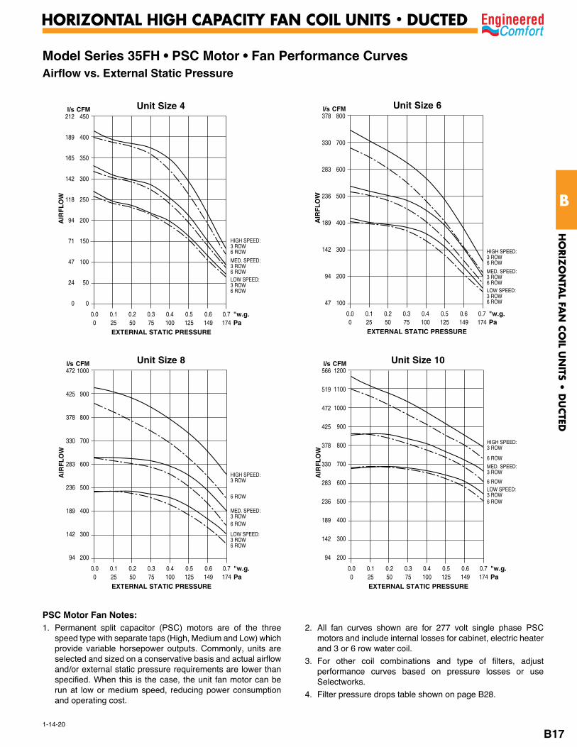
Model Series 35FH • PSC Motor • Fan Performance Curves Airflow vs. External Static Pressure
Unit Size 4450
400
350
300
250
200
150
100
50
0
AIR
FLO
W
l/s CFM212
189
165
142
118
94
71
47
24
0
0.0 0.1 0.2 0.3 0.4 0.5 0.6 0.7 "w.g. 0 25 50 75 100 125 149 174 Pa EXTERNAL STATIC PRESSURE
HIGH SPEED:3 ROW6 ROW
MED. SPEED:3 ROW6 ROWLOW SPEED:3 ROW6 ROW
Unit Size 6800
700
600
500
400
300
200
100
AIR
FLO
W
l/s CFM378
330
283
236
189
142
94
47
0.0 0.1 0.2 0.3 0.4 0.5 0.6 0.7 "w.g. 0 25 50 75 100 125 149 174 Pa EXTERNAL STATIC PRESSURE
Unit Size 8 1000
900
800
700
600
500
400
300
200
AIR
FLO
W
l/s CFM472
425
378
330
283
236
189
142
94
0.0 0.1 0.2 0.3 0.4 0.5 0.6 0.7 "w.g. 0 25 50 75 100 125 149 174 Pa EXTERNAL STATIC PRESSURE
HIGH SPEED:3 ROW6 ROW
MED. SPEED:3 ROW6 ROWLOW SPEED:3 ROW6 ROW
HIGH SPEED:3 ROW
6 ROW
MED. SPEED:3 ROW6 ROW
LOW SPEED:3 ROW6 ROW
Unit Size 101200
1100
1000
900
800
700
600
500
400
300
200
AIR
FLO
W
l/s CFM566
519
472
425
378
330
283
236
189
142
94
0.0 0.1 0.2 0.3 0.4 0.5 0.6 0.7 "w.g. 0 25 50 75 100 125 149 174 Pa EXTERNAL STATIC PRESSURE
HIGH SPEED:3 ROW
6 ROWMED. SPEED:3 ROW
6 ROWLOW SPEED:3 ROW6 ROW
PSC Motor Fan Notes: 1. Permanent split capacitor (PSC) motors are of the three
speed type with separate taps (High, Medium and Low) which provide variable horsepower outputs. Commonly, units are selected and sized on a conservative basis and actual airflow and/or external static pressure requirements are lower than specified. When this is the case, the unit fan motor can be run at low or medium speed, reducing power consumption and operating cost.
2. All fan curves shown are for 277 volt single phase PSC motors and include internal losses for cabinet, electric heater and 3 or 6 row water coil.
3. For other coil combinations and type of filters, adjust performance curves based on pressure losses or use Selectworks.
4. Filter pressure drops table shown on page B28.
HO
RIZ
ON
TAL FA
N C
OIL U
NITS •
DU
CTED
B
HORIZONTAL HIGH CAPACITY FAN COIL UNITS • DUCTED
B17

1-14-20
Model Series 35FH • PSC Motor • Fan Performance Curves Airflow vs. External Static Pressure
Unit Size 121400
1300
1200
1100
1000
900
800
700
600
500
400
AIR
FLO
W
l/s CFM661
613
566
519
472
425
378
330
283
236
189
0.0 0.1 0.2 0.3 0.4 0.5 0.6 0.7 "w.g. 0 25 50 75 100 125 149 174 Pa EXTERNAL STATIC PRESSURE
Unit Size 141500
1400
1300
1200
1100
1000
900
800
700
600
500
400
AIR
FLO
W
l/s CFM708
661
613
566
519
472
425
378
330
283
236
189 0.0 0.1 0.2 0.3 0.4 0.5 0.6 0.7 "w.g. 0 25 50 75 100 125 149 174 Pa EXTERNAL STATIC PRESSURE
l/s CFM
HIGH SPEED:3 ROW
6 ROW
MED. SPEED:3 ROW6 ROWLOW SPEED:3 ROW6 ROW
Unit Size 161700
1600
1500
1400
1300
1200
1100
1000
900
800
AIR
FLO
W
l/s CFM802
755
708
661
613
566
519
472
425
378 0.0 0.1 0.2 0.3 0.4 0.5 0.6 0.7 "w.g. 0 25 50 75 100 125 149 174 Pa EXTERNAL STATIC PRESSURE
HIGH SPEED:3 ROW
HIGH SPEED:6 ROW
MED SPEED:3 ROW
MED SPEED:6 ROW
LOW SPEED:3 ROW
LOW SPEED: 6 ROW
Unit Size 181800
1700
1600
1500
1400
1300
1200
1100
1000
900
800
AIR
FLO
W
849
802
755
708
661
613
566
519
472
425
378
0.0 0.1 0.2 0.3 0.4 0.5 0.6 0.7 "w.g. 0 25 50 75 100 125 149 174 Pa EXTERNAL STATIC PRESSURE
HIGH SPEED:3 ROW
6 ROW
MED. SPEED:3 ROW
6 ROW
LOW SPEED:3 ROW
6 ROW
PSC Motor Fan Notes: 1. Permanent split capacitor (PSC) motors are of the three
speed type with separate taps (High, Medium and Low) which provide variable horsepower outputs. Commonly, units are selected and sized on a conservative basis and actual airflow and/or external static pressure requirements are lower than specified. When this is the case, the unit fan motor can be run at low or medium speed, reducing power consumption and operating cost.
2. All fan curves shown are for 277 volt single phase PSC motors and include internal losses for cabinet, electric heater and 3 or 6 row water coil.
3. For other coil combinations and type of filters, adjust performance curves based on pressure losses or use Selectworks.
4. Filter pressure drops table shown on page B28.
HO
RIZ
ON
TAL FA
N C
OIL U
NITS •
DU
CTED
B
HORIZONTAL HIGH CAPACITY FAN COIL UNITS • DUCTED
B18
1-14-20
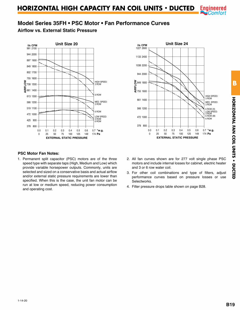
Model Series 35FH • PSC Motor • Fan Performance Curves Airflow vs. External Static Pressure
Unit Size 202100
2000
1900
1800
1700
1600
1500
1400
1300
1200
1100
1000
900
800
AIR
FLO
W
l/s CFM991
944
897
849
802
755
708
661
613
566
519
472
425
378
0.0 0.1 0.2 0.3 0.4 0.5 0.6 0.7 "w.g. 0 25 50 75 100 125 149 174 Pa EXTERNAL STATIC PRESSURE
Unit Size 24 2600
2400
2200
2000
1800
1600
1400
1200
1000
800
AIR
FLO
W
l/s CFM1227
1133
1038
944
849
755
661
566
472
378
0.0 0.1 0.2 0.3 0.4 0.5 0.6 0.7 "w.g. 0 25 50 75 100 125 149 174 Pa EXTERNAL STATIC PRESSURE
HIGH SPEED:3 ROW
6 ROW
MED. SPEED:3 ROW
6 ROW
LOW SPEED:3 ROW6 ROW
HIGH SPEED:3 ROW
6 ROW (H)
MED. SPEED:3 ROW
6 ROW (M)
LOW SPEED:3 ROW
6 ROW
PSC Motor Fan Notes:1. Permanent split capacitor (PSC) motors are of the three
speed type with separate taps (High, Medium and Low) which provide variable horsepower outputs. Commonly, units are selected and sized on a conservative basis and actual airflow and/or external static pressure requirements are lower than specified. When this is the case, the unit fan motor can be run at low or medium speed, reducing power consumption and operating cost.
2. All fan curves shown are for 277 volt single phase PSC motors and include internal losses for cabinet, electric heater and 3 or 6 row water coil.
3. For other coil combinations and type of filters, adjust performance curves based on pressure losses or use Selectworks.
4. Filter pressure drops table shown on page B28.
HO
RIZ
ON
TAL FA
N C
OIL U
NITS •
DU
CTED
B
HORIZONTAL HIGH CAPACITY FAN COIL UNITS • DUCTED
B19
1-14-20
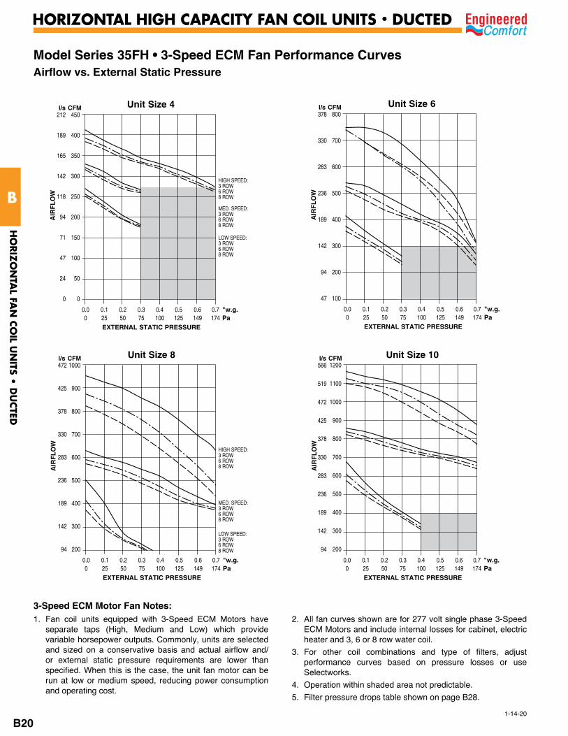
Model Series 35FH • 3-Speed ECM Fan Performance Curves Airflow vs. External Static Pressure
3-Speed ECM Motor Fan Notes:
Unit Size 4450
400
350
300
250
200
150
100
50
0
AIR
FLO
W
l/s CFM212
189
165
142
118
94
71
47
24
0
0.0 0.1 0.2 0.3 0.4 0.5 0.6 0.7 "w.g. 0 25 50 75 100 125 149 174 Pa EXTERNAL STATIC PRESSURE
Unit Size 6800
700
600
500
400
300
200
100
AIR
FLO
W
l/s CFM378
330
283
236
189
142
94
47
0.0 0.1 0.2 0.3 0.4 0.5 0.6 0.7 "w.g. 0 25 50 75 100 125 149 174 Pa EXTERNAL STATIC PRESSURE
Unit Size 8 1000
900
800
700
600
500
400
300
200
AIR
FLO
W
l/s CFM472
425
378
330
283
236
189
142
94
0.0 0.1 0.2 0.3 0.4 0.5 0.6 0.7 "w.g. 0 25 50 75 100 125 149 174 Pa EXTERNAL STATIC PRESSURE
Unit Size 101200
1100
1000
900
800
700
600
500
400
300
200
AIR
FLO
W
l/s CFM566
519
472
425
378
330
283
236
189
142
94
0.0 0.1 0.2 0.3 0.4 0.5 0.6 0.7 "w.g. 0 25 50 75 100 125 149 174 Pa EXTERNAL STATIC PRESSURE
HIGH SPEED:3 ROW6 ROW8 ROW
MED. SPEED:3 ROW6 ROW8 ROW
LOW SPEED:3 ROW6 ROW8 ROW
HIGH SPEED:3 ROW6 ROW8 ROW
MED. SPEED:3 ROW6 ROW8 ROW
LOW SPEED:3 ROW6 ROW8 ROW
1. Fan coil units equipped with 3-Speed ECM Motors have separate taps (High, Medium and Low) which provide variable horsepower outputs. Commonly, units are selected and sized on a conservative basis and actual airflow and/or external static pressure requirements are lower than specified. When this is the case, the unit fan motor can be run at low or medium speed, reducing power consumption and operating cost.
2. All fan curves shown are for 277 volt single phase 3-Speed ECM Motors and include internal losses for cabinet, electric heater and 3, 6 or 8 row water coil.
3. For other coil combinations and type of filters, adjust performance curves based on pressure losses or use Selectworks.
4. Operation within shaded area not predictable. 5. Filter pressure drops table shown on page B28.
HO
RIZ
ON
TAL FA
N C
OIL U
NITS •
DU
CTED
B
HORIZONTAL HIGH CAPACITY FAN COIL UNITS • DUCTED
B20

1-14-20
Model Series 35FH • 3-Speed ECM • Fan Performance Curves Airflow vs. External Static Pressure
Unit Size 121400
1300
1200
1100
1000
900
800
700
600
500
400
AIR
FLO
W
l/s CFM661
613
566
519
472
425
378
330
283
236
189
0.0 0.1 0.2 0.3 0.4 0.5 0.6 0.7 "w.g. 0 25 50 75 100 125 149 174 Pa EXTERNAL STATIC PRESSURE
Unit Size 14l/s CFM1500
1400
1300
1200
1100
1000
900
800
700
600
500
400
AIR
FLO
W
708
661
613
566
519
472
425
378
330
283
236
189 0.0 0.1 0.2 0.3 0.4 0.5 0.6 0.7 "w.g. 0 25 50 75 100 125 149 174 Pa EXTERNAL STATIC PRESSURE
Unit Size 181800
1700
1600
1500
1400
1300
1200
1100
1000
900
800
AIR
FLO
W
l/s CFM849
802
755
708
661
613
566
519
472
425
378
0.0 0.1 0.2 0.3 0.4 0.5 0.6 0.7 "w.g. 0 25 50 75 100 125 149 174 Pa EXTERNAL STATIC PRESSURE
Unit Size 161700
1600
1500
1400
1300
1200
1100
1000
900
800
AIR
FLO
W
l/s CFM802
755
708
661
613
566
519
472
425
378 0.0 0.1 0.2 0.3 0.4 0.5 0.6 0.7 "w.g. 0 25 50 75 100 125 149 174 Pa EXTERNAL STATIC PRESSURE
HIGH SPEED:3 ROW6 ROW8 ROW
MED. SPEED:3 ROW6 ROW8 ROW
LOW SPEED:3 ROW6 ROW8 ROW
HIGH SPEED:3 ROW6 ROW8 ROW
MED. SPEED:3 ROW6 ROW8 ROW
LOW SPEED:3 ROW6 ROW8 ROW
HIGH SPEED:3 ROW6 ROW8 ROW
MED. SPEED:3 ROW6 ROW8 ROW
LOW SPEED:3 ROW6 ROW8 ROW
HIGH SPEED:3 ROW6 ROW8 ROW
MED. SPEED:3 ROW6 ROW8 ROW
LOW SPEED:3 ROW6 ROW8 ROW
3-Speed ECM Motor Fan Notes:1. Fan coil units equipped with 3-Speed ECM Motors have
separate taps (High, Medium and Low) which provide variable horsepower outputs. Commonly, units are selected and sized on a conservative basis and actual airflow and/or external static pressure requirements are lower than specified. When this is the case, the unit fan motor can be run at low or medium speed, reducing power consumption and operating cost.
2. All fan curves shown are for 277 volt single phase 3-Speed ECM Motors and include internal losses for cabinet, electric heater and 3, 6 or 8 row water coil.
3. For other coil combinations and type of filters, adjust performance curves based on pressure losses or use Selectworks.
4. Filter pressure drops table shown on page B28.
HO
RIZ
ON
TAL FA
N C
OIL U
NITS •
DU
CTED
B
HORIZONTAL HIGH CAPACITY FAN COIL UNITS • DUCTED
B21
1-14-20
3-Speed ECM Motor Fan Notes:
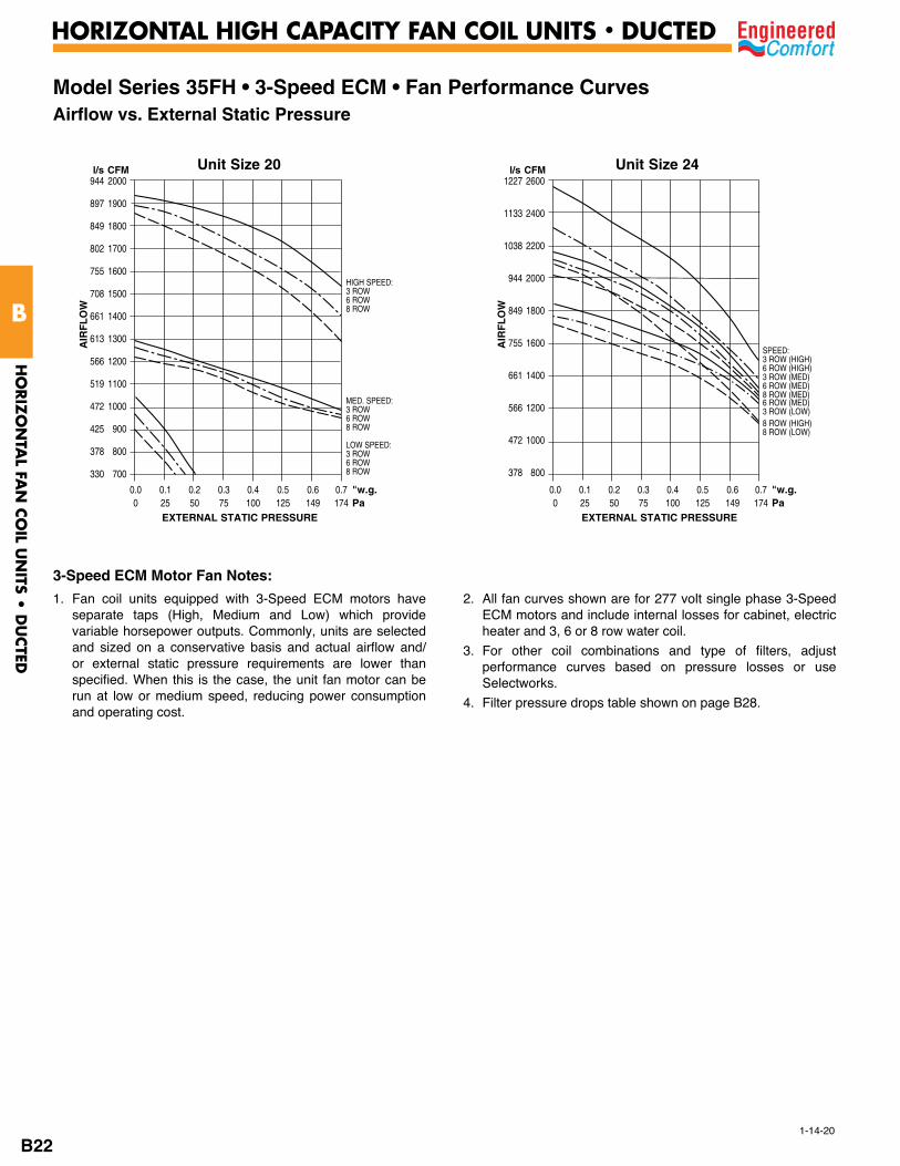
Model Series 35FH • 3-Speed ECM • Fan Performance Curves Airflow vs. External Static Pressure
Unit Size 202000
1900
1800
1700
1600
1500
1400
1300
1200
1100
1000
900
800
700
AIR
FLO
W
l/s CFM944
897
849
802
755
708
661
613
566
519
472
425
378
330
0.0 0.1 0.2 0.3 0.4 0.5 0.6 0.7 "w.g. 0 25 50 75 100 125 149 174 Pa EXTERNAL STATIC PRESSURE
Unit Size 24 2600
2400
2200
2000
1800
1600
1400
1200
1000
800
AIR
FLO
W
l/s CFM1227
1133
1038
944
849
755
661
566
472
378
0.0 0.1 0.2 0.3 0.4 0.5 0.6 0.7 "w.g. 0 25 50 75 100 125 149 174 Pa EXTERNAL STATIC PRESSURE
HIGH SPEED:3 ROW6 ROW8 ROW
MED. SPEED:3 ROW6 ROW8 ROW
LOW SPEED:3 ROW6 ROW8 ROW
SPEED:3 ROW (HIGH)6 ROW (HIGH)3 ROW (MED)6 ROW (MED)8 ROW (MED)6 ROW (MED)3 ROW (LOW)8 ROW (HIGH)8 ROW (LOW)
1. Fan coil units equipped with 3-Speed ECM motors have separate taps (High, Medium and Low) which provide variable horsepower outputs. Commonly, units are selected and sized on a conservative basis and actual airflow and/or external static pressure requirements are lower than specified. When this is the case, the unit fan motor can be run at low or medium speed, reducing power consumption and operating cost.
2. All fan curves shown are for 277 volt single phase 3-Speed ECM motors and include internal losses for cabinet, electric heater and 3, 6 or 8 row water coil.
3. For other coil combinations and type of filters, adjust performance curves based on pressure losses or use Selectworks.
4. Filter pressure drops table shown on page B28.
HO
RIZ
ON
TAL FA
N C
OIL U
NITS •
DU
CTED
B
HORIZONTAL HIGH CAPACITY FAN COIL UNITS • DUCTED
B22
1-14-20
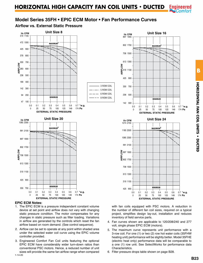
Model Series 35FH • EPIC ECM Motor • Fan Performance CurvesAirflow vs. External Static Pressure
Unit Size 161900
1700
1500
1300
1100
900
700
500
300
AIR
FLO
W
l/s CFM897
802
708
613
519
425
330
236
142
0.0 0.1 0.2 0.3 0.4 0.5 0.6 0.7 "w.g. 0 25 50 75 100 125 149 174 Pa EXTERNAL STATIC PRESSURE
Unit Size 202300
2100
1900
1700
1500
1300
1100
900
700
AIR
FLO
W
l/s CFM1085
991
897
802
708
613
519
425
330
Unit Size 24 2700
2500
2300
2100
1900
1700
1500
1300
1100
900
AIR
FLO
Wl/s CFM
1274
1180
1085
991
897
802
708
613
519
425
Unit Size 81100
1000
900
800
700
600
500
400
300
200
100
AIR
FLO
W
l/s CFM519
472
425
378
330
283
236
189
142
94
47
0.0 0.1 0.2 0.3 0.4 0.5 0.6 0.7 "w.g. 0 25 50 75 100 125 149 174 Pa EXTERNAL STATIC PRESSURE
MINIMUMMINIMUM
MINIMUM MINIMUM
3 ROW COIL
5 ROW COIL
6 ROW COIL
8 ROW COIL
EPIC ECM Notes:
MAXIMUM5
MAXIMUM5
MAXIMUM5MAXIMUM5
1. The EPIC ECM is a pressure independent constant volume device at set point and airflow does not vary with changing static pressure condition. The motor compensates for any changes in static pressure such as filter loading. Variations in airflow are generated by the controls which reset the fan airflow based on room demand. (See control sequence).
2. Airflow can be set to operate at any point within shaded area under the selected water coil curve using the EPIC volume controller provided.
3. Engineered Comfort Fan Coil units featuring the optional EPIC ECM have considerably wider turn-down ratios than conventional PSC motors. Hence, a reduced number of unit sizes will provide the same fan airflow range when compared
with fan coils equipped with PSC motors. A reduction in the number of different fan coil sizes, required on a typical project, simplifies design lay-out, installation and reduces inventory of field service parts.
4. Fan curves shown are applicable to 120/208/240 and 277 volt, single phase EPIC ECM (motors).
5. The maximum curve represents unit performance with a 3-row coil. For one (1) or two (2) row hot water coils (35FHW heating unit) performance will be slightly better. Model 35FHE (electric heat only) performance data will be comparable to a one (1) row unit. See SelectWorks for performance data Characteristics.
6. Filter pressure drops table shown on page B28.
0.0 0.1 0.2 0.3 0.4 0.5 0.6 0.7 "w.g. 0 25 50 75 100 125 149 174 Pa EXTERNAL STATIC PRESSURE
0.0 0.1 0.2 0.3 0.4 0.5 0.6 0.7 "w.g. 0 25 50 75 100 125 149 174 Pa EXTERNAL STATIC PRESSURE
HO
RIZ
ON
TAL FA
N C
OIL U
NITS •
DU
CTED
B
HORIZONTAL HIGH CAPACITY FAN COIL UNITS • DUCTED
B23

1-14-20
Model Series 35FH • EPIC ECM Motor • Fan Performance CurvesAirflow vs. External Static Pressure
Unit Size 404200
4000
3800
3600
3400
3200
3000
2800
2600
2400
2200
2000
1800
AIR
FLO
W
l/s CFM1982
1888
1793
1699
1604
1510
1416
1321
1227
1133
1038
944
849
0.0 0.2 0.4 0.6 0.8 1.0 1.2 1.3 "w.g. 0 50 100 149 199 249 298 323 Pa EXTERNAL STATIC PRESSURE
Unit Size 303600
3400
3200
3000
2800
2600
2400
2200
2000
1800
1600
1400
1200
1000
800
AIR
FLO
W
l/s CFM1699
1604
1510
1416
1321
1227
1133
1038
944
849
755
661
566
472
378
0.0 0.1 0.2 0.3 0.4 0.5 0.6 0.7 0.8 0.9 1.0 "w.g. 0 25 50 75 100 125 149 174 199 224 249 Pa EXTERNAL STATIC PRESSURE
MINIMUM
3 ROW COIL
5 ROW COIL
6 ROW COIL
8 ROW COIL
EPIC ECM Notes:
MAXIMUM5 MAXIMUM5
1. The EPIC ECM is a pressure independent constant volume device at set point and airflow does not vary with changing static pressure condition. The motor compensates for any changes in static pressure such as filter loading. Variations in airflow are generated by the controls which reset the fan airflow based on room demand. (See control sequence).
2. Airflow can be set to operate at any point within shaded area under the selected water coil curve using the EPIC volume controller provided.
3. Engineered Comfort Fan Coil units featuring the optional EPIC ECM have considerably wider turn-down ratios than conventional PSC motors. Hence, a reduced number of unit sizes will provide the same fan airflow range when compared
with fan coils equipped with PSC motors. A reduction in the number of different fan coil sizes, required on a typical project, simplifies design lay-out, installation and reduces inventory of field service parts.
4. Fan curves shown are applicable to 120/208/240 and 277 volt, single phase EPIC ECM (motors).
5. The maximum curve represents unit performance with a 3-row coil. For one (1) or two (2) row hot water coils (35FHW heating unit) performance will be slightly better. Model 35FHE (electric heat only) performance data will be comparable to a one (1) row unit. See SelectWorks for performance data Characteristics.
6. Filter pressure drops table shown on page B28.
MINIMUM
HO
RIZ
ON
TAL FA
N C
OIL U
NITS •
DU
CTED
B
HORIZONTAL HIGH CAPACITY FAN COIL UNITS • DUCTED
B24
1-6-20
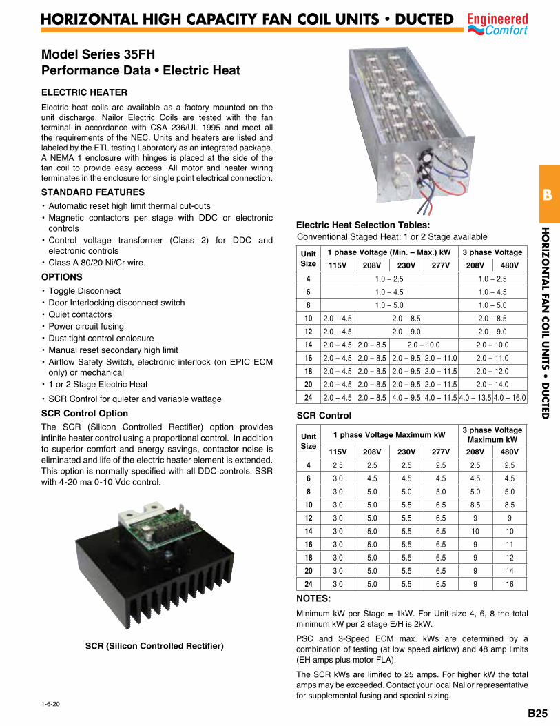
Model Series 35FH Performance Data • Electric HeatELECTRIC HEATERElectric heat coils are available as a factory mounted on the unit discharge. Nailor Electric Coils are tested with the fan terminal in accordance with CSA 236/UL 1995 and meet all the requirements of the NEC. Units and heaters are listed and labeled by the ETL testing Laboratory as an integrated package. A NEMA 1 enclosure with hinges is placed at the side of the fan coil to provide easy access. All motor and heater wiring terminates in the enclosure for single point electrical connection.
STANDARD FEATURES• Automatic reset high limit thermal cut-outs• Magnetic contactors per stage with DDC or electronic
controls • Control voltage transformer (Class 2) for DDC and
electronic controls• Class A 80/20 Ni/Cr wire.
OPTIONS• Toggle Disconnect• Door Interlocking disconnect switch • Quiet contactors• Power circuit fusing• Dust tight control enclosure• Manual reset secondary high limit• Airflow Safety Switch, electronic interlock (on EPIC ECM
only) or mechanical• 1 or 2 Stage Electric Heat
• SCR Control for quieter and variable wattage
SCR Control OptionThe SCR (Silicon Controlled Rectifier) option provides infinite heater control using a proportional control. In addition to superior comfort and energy savings, contactor noise is eliminated and life of the electric heater element is extended. This option is normally specified with all DDC controls. SSR with 4-20 ma 0-10 Vdc control.
Electric Heat Selection Tables:
Unit Size
1 phase Voltage (Min. – Max.) kW 3 phase Voltage
115V 208V 230V 277V 208V 480V
4 1.0 – 2.5 1.0 – 2.5
6 1.0 – 4.5 1.0 – 4.5
8 1.0 – 5.0 1.0 – 5.0
10 2.0 – 4.5 2.0 – 8.5 2.0 – 8.5
12 2.0 – 4.5 2.0 – 9.0 2.0 – 9.0
14 2.0 – 4.5 2.0 – 8.5 2.0 – 10.0 2.0 – 10.0
16 2.0 – 4.5 2.0 – 8.5 2.0 – 9.5 2.0 – 11.0 2.0 – 11.0
18 2.0 – 4.5 2.0 – 8.5 2.0 – 9.5 2.0 – 11.5 2.0 – 12.0
20 2.0 – 4.5 2.0 – 8.5 2.0 – 9.5 2.0 – 11.5 2.0 – 14.0
24 2.0 – 4.5 2.0 – 8.5 4.0 – 9.5 4.0 – 11.5 4.0 – 13.5 4.0 – 16.0
SCR Control
Unit Size
1 phase Voltage Maximum kW 3 phase VoltageMaximum kW
115V 208V 230V 277V 208V 480V
4 2.5 2.5 2.5 2.5 2.5 2.5
6 3.0 4.5 4.5 4.5 4.5 4.5
8 3.0 5.0 5.0 5.0 5.0 5.0
10 3.0 5.0 5.5 6.5 8.5 8.5
12 3.0 5.0 5.5 6.5 9 9
14 3.0 5.0 5.5 6.5 10 10
16 3.0 5.0 5.5 6.5 9 11
18 3.0 5.0 5.5 6.5 9 12
20 3.0 5.0 5.5 6.5 9 14
24 3.0 5.0 5.5 6.5 9 16
NOTES:Minimum kW per Stage = 1kW. For Unit size 4, 6, 8 the total minimum kW per 2 stage E/H is 2kW.
PSC and 3-Speed ECM max. kWs are determined by a combination of testing (at low speed airflow) and 48 amp limits (EH amps plus motor FLA).
The SCR kWs are limited to 25 amps. For higher kW the total amps may be exceeded. Contact your local Nailor representative for supplemental fusing and special sizing.
Conventional Staged Heat: 1 or 2 Stage available
SCR (Silicon Controlled Rectifier)
HO
RIZ
ON
TAL FA
N C
OIL U
NITS •
DU
CTED
B
HORIZONTAL HIGH CAPACITY FAN COIL UNITS • DUCTED
B25
Unit Size
VoltageNo. ofFans/
Motors
EPIC ECM 3-speed ECM PSC Motor
FLA Full Load Watts FLA Full Load
Watts FLA Full Load Watts
4
120 1/1 1.5
120
1.5
175208 1/1 1.4 0.7240 1/1 1.4 0.7277 1/1 0.9 0.6
6
120 1/1 2.9
220
2.5
280208 1/1 1.9 1.1240 1/1 1.9 1.2277 1/1 1.5 1.1
8
120 1/1 3.3
260
3.3
330
2.7
310208 1/1 2.2 2.2 1.3240 1/1 2.1 2.2 1.3277 1/1 2.1 1.9 1.2
10
120 1/1 3.6
370
3.8
450208 1/1 2.4 1.9240 1/1 2.4 1.9277 1/1 2.4 1.5
12
120 1/1 4.3
430
4.1
500208 1/1 2.8 2.0240 1/1 2.7 2.0277 1/1 2.9 1.6
14
120 1/1 5.1
470
4.6
575208 1/1 3,4 2.3240 1/1 3.4 2.3277 1/1 3.2 2.0
16
120 1/1 7.2
640
6.0
690
7.1
785208 1/1 4.9 4.0 3.0240 1/1 4.7 4.0 3.0277 1/1 4.6 3.7 2.7
18
120 1/1 6.4
700
7.7
830208 1/1 4.5 3.3240 1/1 4.5 3.4277 1/1 4.3 3.2
20
120 1/1 9.6
850
7.7
860
8.2
935208 1/1 6.3 5.6 4.3240 1/1 6.1 5.6 4.4277 1/1 6.0 5.3 3.6
24
120 2/2 11.8
1110
9.4
880
8.3
1000208 2/2 7.9 6.0 4.0240 2/2 7.8 6.0 4.0277 2/2 7.5 6.1 3.6
30
120 2/2 12.6
1260208 2/2 8.7240 2/2 8.4277 2/2 8.0
40
120 2/2 19.4
1870208 2/2 12.5240 2/2 11.9277 2/2 11.6
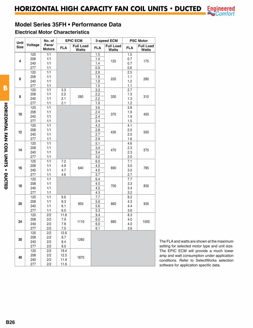
Model Series 35FH • Performance Data Electrical Motor Characteristics
The FLA and watts are shown at the maximum setting for selected motor type and unit size. The EPIC ECM will provide a much lower amp and watt consumption under application conditions. Refer to SelectWorks selection software for application specific data.
HO
RIZ
ON
TAL FA
N C
OIL U
NITS •
DU
CTED
B
HORIZONTAL HIGH CAPACITY FAN COIL UNITS • DUCTED
B26

Model Series 35FH • Energy Consumption Comparison ChartsEPIC ECM vs. 3-Speed PSC Motors3 Row Coil, 0.20" w.g. ESP, 277 Volt Motors
200 300 400 500 600 700 800 900 1000
400
350
300
250
200
150
100
50
AIRFLOW CFM
WAT
TS
EPIC ECMSIZE 8
HI.
LO.
MED.
800 1000 1200 1400 1600 1800 2000 2200 2400 2800
1000
900
800
700
600
500
400
300
200
100
0
AIRFLOW CFM
WAT
TS
SIZE 4
SIZE 6 SIZE 8
HI.
LO.MED.
LO.
MED.
EPIC ECMSIZE 24
SIZE 20
HI.
400 600 800 1000 1200 1400 1600 1800
700
600
500
400
300
200
100
0
AIRFLOW CFMW
ATTS
EPIC ECMSIZE 16
HI.
LO.
MED.
SIZE 12SIZE 10
LO.
MED.
HI.HI.
LO.
MED.
SIZE 16
600 800 1000 1200 1400 1600 1800 2000
900
800
700
600
500
400
300
200
100
0
AIRFLOW CFM
WAT
TS
HI.
EPIC ECMSIZE 20
LO.MED.
3-SPEED PSC
3-SPEED PSC
3-SPEED PSC
3-SPEED PSCSIZE 18
SIZE 20
LO.
MED.
HI.
HI.
MED.
LO.
HI.
LO.
MED.
SIZE 24
1. The graphs plot and illustrate the difference in motor power consumption in Watts between EPIC ECM and 3-speed PSC motors over the fan flow range for each unit size.
2. The EPIC ECM has a much wider airflow range than a 3-speed PSC, hence the reduced number of sizes required.
3. The EPIC ECM is more energy efficient at all operating points. At high speed airflow PSC Settings, the EPIC ECM power consumption is on average 65%of the PSC motor which is 35% in energy savings. However, most fan coils are designed and sized to operate at medium or low speed most of the time. At medium and low speed airflow settings, the EPIC ECM motor power consumption is on average 54% and 47% respectively compared to the PSC motor. This is 46% and 53% in energy savings. Therefore, energy savings are even more substantial at lower speeds. The savings are even greater when an EPIC ECM variable air volume sequence is selected.
NOTES:
Unit Size Airflow Settings
PSC ECM Low Medium High
4
8
N/A 54% 43%
6 34% 47% 50%
8 55% 62% 80%
10
16
46% 45% 52%
12 48% 54% 67%
16 52% 60% 75%
1820
38% 41% 62%
20 34% 43% 71%
24 24 62% 73% 87%
Average 46% 53% 65%
Percentage (%) ECM Motor Energy Consumption vs. 3-speed PSC Motor
% = ECM watts/PSC watts x 100
HO
RIZ
ON
TAL FA
N C
OIL U
NITS •
DU
CTED
B
HORIZONTAL HIGH CAPACITY FAN COIL UNITS • DUCTED
B27
12-26-18
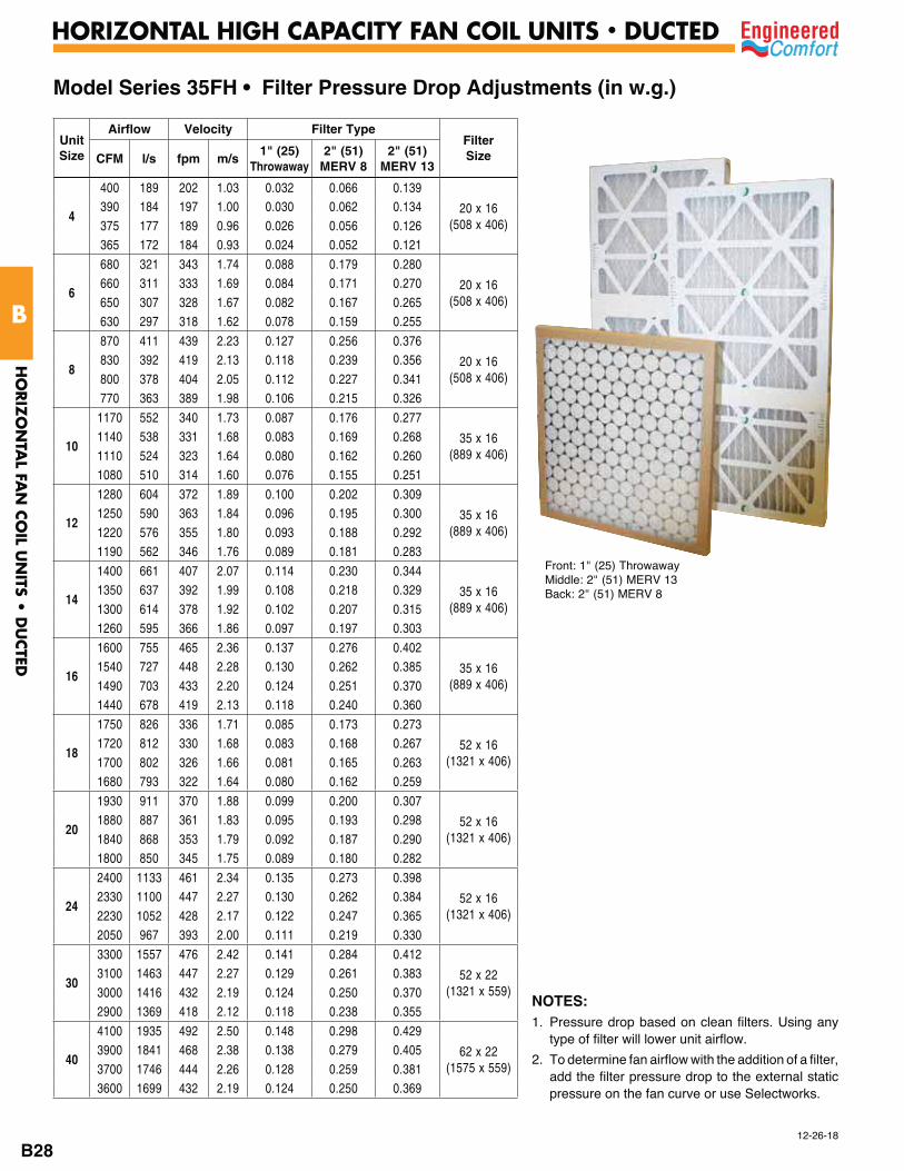
Model Series 35FH • Filter Pressure Drop Adjustments (in w.g.)
Unit Size
Airflow Velocity Filter TypeFilter SizeCFM l/s fpm m/s
1" (25) Throwaway
2" (51) MERV 8
2" (51) MERV 13
4
400 189 202 1.03 0.032 0.066 0.139
20 x 16 (508 x 406)
390 184 197 1.00 0.030 0.062 0.134375 177 189 0.96 0.026 0.056 0.126365 172 184 0.93 0.024 0.052 0.121
6
680 321 343 1.74 0.088 0.179 0.280
20 x 16 (508 x 406)
660 311 333 1.69 0.084 0.171 0.270650 307 328 1.67 0.082 0.167 0.265630 297 318 1.62 0.078 0.159 0.255
8
870 411 439 2.23 0.127 0.256 0.376
20 x 16 (508 x 406)
830 392 419 2.13 0.118 0.239 0.356800 378 404 2.05 0.112 0.227 0.341770 363 389 1.98 0.106 0.215 0.326
10
1170 552 340 1.73 0.087 0.176 0.277
35 x 16 (889 x 406)
1140 538 331 1.68 0.083 0.169 0.2681110 524 323 1.64 0.080 0.162 0.2601080 510 314 1.60 0.076 0.155 0.251
12
1280 604 372 1.89 0.100 0.202 0.309
35 x 16 (889 x 406)
1250 590 363 1.84 0.096 0.195 0.3001220 576 355 1.80 0.093 0.188 0.2921190 562 346 1.76 0.089 0.181 0.283
14
1400 661 407 2.07 0.114 0.230 0.344
35 x 16 (889 x 406)
1350 637 392 1.99 0.108 0.218 0.3291300 614 378 1.92 0.102 0.207 0.3151260 595 366 1.86 0.097 0.197 0.303
16
1600 755 465 2.36 0.137 0.276 0.402
35 x 16 (889 x 406)
1540 727 448 2.28 0.130 0.262 0.3851490 703 433 2.20 0.124 0.251 0.3701440 678 419 2.13 0.118 0.240 0.360
18
1750 826 336 1.71 0.085 0.173 0.273
52 x 16 (1321 x 406)
1720 812 330 1.68 0.083 0.168 0.2671700 802 326 1.66 0.081 0.165 0.2631680 793 322 1.64 0.080 0.162 0.259
20
1930 911 370 1.88 0.099 0.200 0.307
52 x 16 (1321 x 406)
1880 887 361 1.83 0.095 0.193 0.2981840 868 353 1.79 0.092 0.187 0.2901800 850 345 1.75 0.089 0.180 0.282
24
2400 1133 461 2.34 0.135 0.273 0.398
52 x 16 (1321 x 406)
2330 1100 447 2.27 0.130 0.262 0.3842230 1052 428 2.17 0.122 0.247 0.3652050 967 393 2.00 0.111 0.219 0.330
30
3300 1557 476 2.42 0.141 0.284 0.412
52 x 22 (1321 x 559)
3100 1463 447 2.27 0.129 0.261 0.3833000 1416 432 2.19 0.124 0.250 0.3702900 1369 418 2.12 0.118 0.238 0.355
40
4100 1935 492 2.50 0.148 0.298 0.429
62 x 22 (1575 x 559)
3900 1841 468 2.38 0.138 0.279 0.4053700 1746 444 2.26 0.128 0.259 0.3813600 1699 432 2.19 0.124 0.250 0.369
Front: 1" (25) ThrowawayMiddle: 2" (51) MERV 13Back: 2" (51) MERV 8
NOTES:1. Pressure drop based on clean filters. Using any
type of filter will lower unit airflow.
2. To determine fan airflow with the addition of a filter, add the filter pressure drop to the external static pressure on the fan curve or use Selectworks.
HO
RIZ
ON
TAL FA
N C
OIL U
NITS •
DU
CTED
B
HORIZONTAL HIGH CAPACITY FAN COIL UNITS • DUCTED
B28
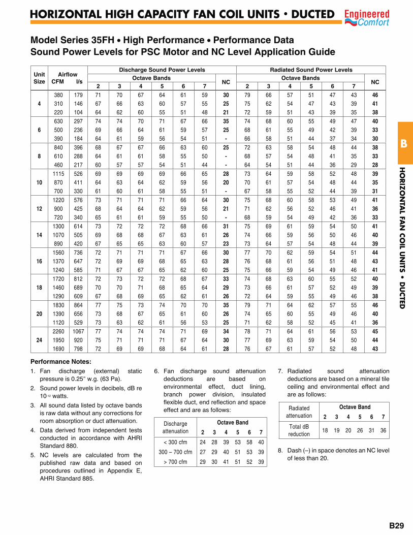
Model Series 35FH • High Performance • Performance DataSound Power Levels for PSC Motor and NC Level Application Guide
Unit Size
Airflow CFM l/s
Discharge Sound Power Levels Radiated Sound Power LevelsOctave Bands
NCOctave Bands
NC2 3 4 5 6 7 2 3 4 5 6 7
4380 179 71 70 67 64 61 59 30 79 66 57 51 47 43 46310 146 67 66 63 60 57 55 25 75 62 54 47 43 39 41220 104 64 62 60 55 51 48 21 72 59 51 43 39 35 38
6630 297 74 74 70 71 67 66 35 74 68 60 55 49 47 40500 236 69 66 64 61 59 57 25 68 61 55 49 42 39 33390 184 64 61 59 56 54 51 - 66 58 51 44 37 34 30
8840 396 68 67 67 66 63 60 25 72 63 58 54 48 44 38610 288 64 61 61 58 55 50 - 68 57 54 48 41 35 33460 217 60 57 57 54 51 44 - 64 54 51 44 36 29 28
101115 526 69 69 69 69 66 65 28 73 64 59 58 52 48 39870 411 64 63 64 62 59 56 20 70 61 57 54 48 44 35700 330 61 60 61 58 55 51 - 67 58 55 52 44 39 31
121220 576 73 71 71 71 66 64 30 75 68 60 58 53 49 41900 425 68 64 64 62 59 56 21 71 62 56 52 46 41 36720 340 65 61 61 59 55 50 - 68 59 54 49 42 36 33
141300 614 73 72 72 72 68 66 31 75 69 61 59 54 50 411070 505 69 68 68 67 63 61 26 74 66 59 56 50 46 40890 420 67 65 65 63 60 57 23 73 64 57 54 48 44 39
161560 736 72 71 71 71 67 66 30 77 70 62 59 54 51 441370 647 72 69 69 68 65 63 28 76 68 61 56 51 48 431240 585 71 67 67 65 62 60 25 75 66 59 54 49 46 41
181720 812 72 73 72 72 68 67 33 74 68 63 60 55 52 401460 689 70 70 71 68 65 64 29 73 66 61 57 52 49 391290 609 67 68 69 65 62 61 26 72 64 59 55 49 46 38
201830 864 77 75 73 74 70 70 35 79 71 64 62 57 55 461390 656 73 68 67 65 61 60 26 74 65 60 55 49 46 401120 529 73 63 62 61 56 53 25 71 62 58 52 45 41 36
242260 1067 77 74 74 74 71 69 34 78 71 64 61 56 53 451950 920 75 71 71 71 67 64 30 77 69 63 59 54 50 441690 798 72 69 69 68 64 61 28 76 67 61 57 52 48 43
Performance Notes:1. Fan discharge (external) static
pressure is 0.25" w.g. (63 Pa).
2. Sound power levels in decibels, dB re 10-12 watts.
3. All sound data listed by octave bands is raw data without any corrections for room absorption or duct attenuation.
4. Data derived from independent tests conducted in accordance with AHRI Standard 880.
5. NC levels are calculated from the published raw data and based on procedures outlined in Appendix E, AHRI Standard 885.
6. Fan discharge sound attenuation deductions are based on environmental effect, duct lining, branch power division, insulated flexible duct, end reflection and space effect and are as follows:
7. Radiated sound attenuation deductions are based on a mineral tile ceiling and environmental effect and are as follows:
8. Dash (–) in space denotes an NC level of less than 20.
Discharge attenuation
Octave Band
2 3 4 5 6 7
< 300 cfm 24 28 39 53 58 40
300 – 700 cfm 27 29 40 51 53 39
> 700 cfm 29 30 41 51 52 39
Radiated attenuation
Octave Band
2 3 4 5 6 7
Total dB reduction
18 19 20 26 31 36
HO
RIZ
ON
TAL FA
N C
OIL U
NITS •
DU
CTED
B
HORIZONTAL HIGH CAPACITY FAN COIL UNITS • DUCTED
B29
9-12-18
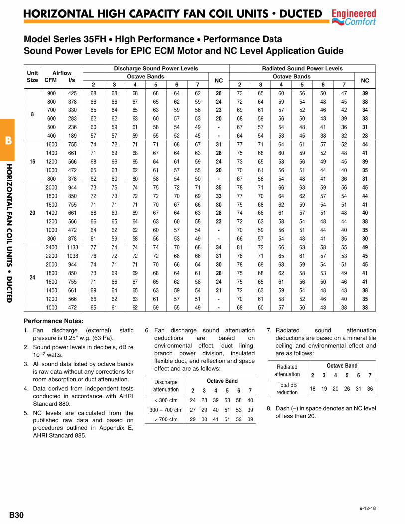
Model Series 35FH • High Performance • Performance DataSound Power Levels for EPIC ECM Motor and NC Level Application Guide
Unit Size
AirflowCFM l/s
Discharge Sound Power Levels Radiated Sound Power Levels Octave Bands
NCOctave Bands
NC2 3 4 5 6 7 2 3 4 5 6 7
8
900 425 68 68 68 68 64 62 26 73 65 60 56 50 47 39800 378 66 66 67 65 62 59 24 72 64 59 54 48 45 38700 330 65 64 65 63 59 56 23 69 61 57 52 46 42 34600 283 62 62 63 60 57 53 20 68 59 56 50 43 39 33500 236 60 59 61 58 54 49 - 67 57 54 48 41 36 31400 189 57 57 59 55 52 45 - 64 54 53 45 38 32 28
16
1600 755 74 72 71 71 68 67 31 77 71 64 61 57 52 441400 661 71 69 68 67 64 63 28 75 68 60 59 52 48 411200 566 68 66 65 64 61 59 24 73 65 58 56 49 45 391000 472 65 63 62 61 57 55 20 70 61 56 51 44 40 35800 378 62 60 60 58 54 50 - 67 58 54 48 41 36 31
20
2000 944 73 75 74 75 72 71 35 78 71 66 63 59 56 451800 850 72 73 72 72 70 69 33 77 70 64 62 57 54 441600 755 71 71 71 70 67 66 30 75 68 62 59 54 51 411400 661 68 69 69 67 64 63 28 74 66 61 57 51 48 401200 566 66 65 64 63 60 58 23 72 63 58 54 48 44 381000 472 64 62 62 60 57 54 - 70 59 56 51 44 40 35800 378 61 59 58 56 53 49 - 66 57 54 48 41 35 30
24
2400 1133 77 74 74 74 70 68 34 81 72 66 63 58 55 492200 1038 76 72 72 72 68 66 31 78 71 65 61 57 53 452000 944 74 71 71 70 66 64 30 78 69 63 59 54 51 451800 850 73 69 69 68 64 61 28 75 68 62 58 53 49 411600 755 71 66 67 65 62 58 24 75 65 61 56 50 46 411400 661 69 64 65 63 59 54 21 72 63 59 54 48 43 381200 566 66 62 63 61 57 51 - 70 61 58 52 46 40 351000 472 65 61 62 59 55 49 - 68 60 57 50 43 38 33
Performance Notes:1. Fan discharge (external) static
pressure is 0.25" w.g. (63 Pa).
2. Sound power levels in decibels, dB re 10-12 watts.
3. All sound data listed by octave bands is raw data without any corrections for room absorption or duct attenuation.
4. Data derived from independent tests conducted in accordance with AHRI Standard 880.
5. NC levels are calculated from the published raw data and based on procedures outlined in Appendix E, AHRI Standard 885.
6. Fan discharge sound attenuation deductions are based on environmental effect, duct lining, branch power division, insulated flexible duct, end reflection and space effect and are as follows:
7. Radiated sound attenuation deductions are based on a mineral tile ceiling and environmental effect and are as follows:
8. Dash (–) in space denotes an NC level of less than 20.
Discharge attenuation
Octave Band
2 3 4 5 6 7
< 300 cfm 24 28 39 53 58 40
300 – 700 cfm 27 29 40 51 53 39
> 700 cfm 29 30 41 51 52 39
Radiated attenuation
Octave Band
2 3 4 5 6 7
Total dB reduction
18 19 20 26 31 36H
ORIZ
ON
TAL FA
N C
OIL U
NITS •
DU
CTED
B
HORIZONTAL HIGH CAPACITY FAN COIL UNITS • DUCTED
B30
9-12-18
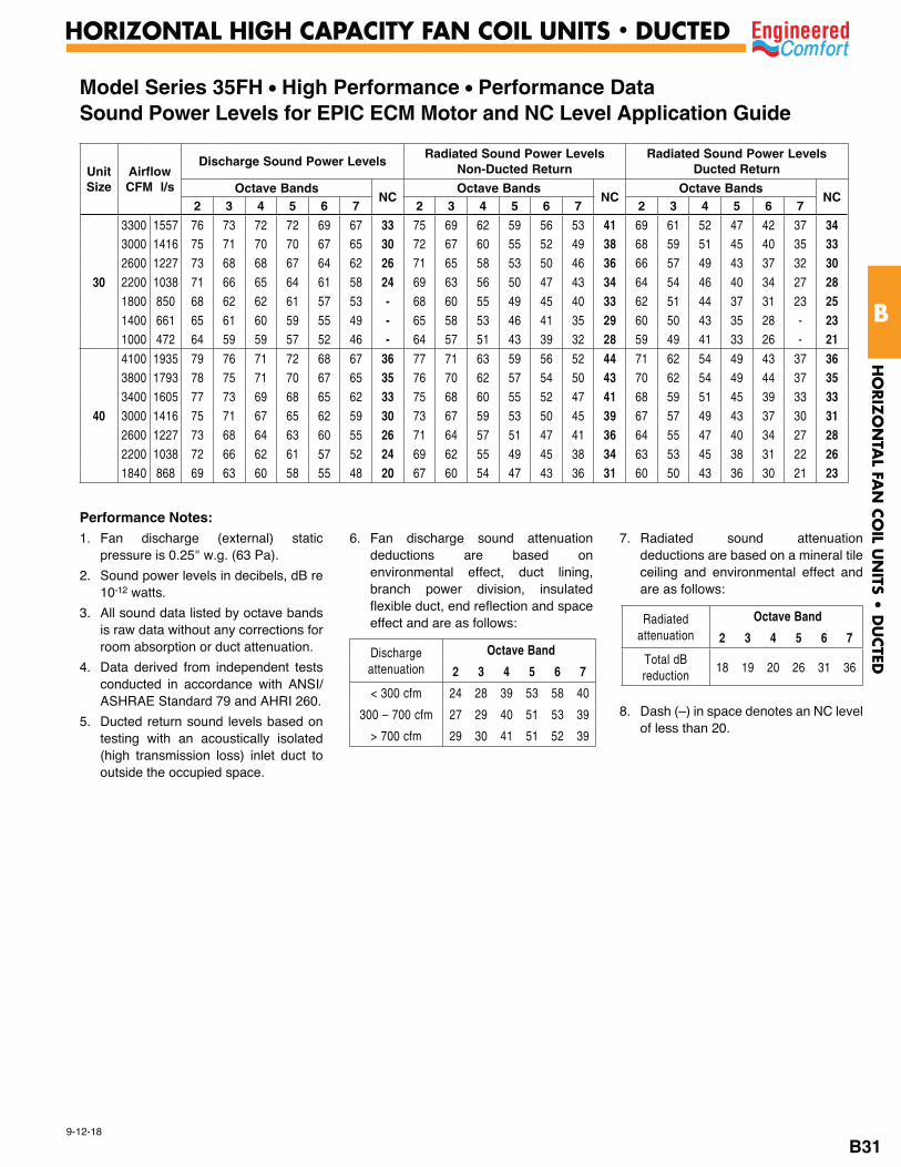
Model Series 35FH • High Performance • Performance DataSound Power Levels for EPIC ECM Motor and NC Level Application Guide
Unit Size
AirflowCFM l/s
Discharge Sound Power Levels Radiated Sound Power Levels
Non-Ducted ReturnRadiated Sound Power Levels
Ducted Return
Octave BandsNC
Octave BandsNC
Octave BandsNC
2 3 4 5 6 7 2 3 4 5 6 7 2 3 4 5 6 7
30
3300 1557 76 73 72 72 69 67 33 75 69 62 59 56 53 41 69 61 52 47 42 37 343000 1416 75 71 70 70 67 65 30 72 67 60 55 52 49 38 68 59 51 45 40 35 332600 1227 73 68 68 67 64 62 26 71 65 58 53 50 46 36 66 57 49 43 37 32 302200 1038 71 66 65 64 61 58 24 69 63 56 50 47 43 34 64 54 46 40 34 27 281800 850 68 62 62 61 57 53 - 68 60 55 49 45 40 33 62 51 44 37 31 23 251400 661 65 61 60 59 55 49 - 65 58 53 46 41 35 29 60 50 43 35 28 - 231000 472 64 59 59 57 52 46 - 64 57 51 43 39 32 28 59 49 41 33 26 - 21
40
4100 1935 79 76 71 72 68 67 36 77 71 63 59 56 52 44 71 62 54 49 43 37 363800 1793 78 75 71 70 67 65 35 76 70 62 57 54 50 43 70 62 54 49 44 37 353400 1605 77 73 69 68 65 62 33 75 68 60 55 52 47 41 68 59 51 45 39 33 333000 1416 75 71 67 65 62 59 30 73 67 59 53 50 45 39 67 57 49 43 37 30 312600 1227 73 68 64 63 60 55 26 71 64 57 51 47 41 36 64 55 47 40 34 27 282200 1038 72 66 62 61 57 52 24 69 62 55 49 45 38 34 63 53 45 38 31 22 261840 868 69 63 60 58 55 48 20 67 60 54 47 43 36 31 60 50 43 36 30 21 23
Performance Notes:1. Fan discharge (external) static
pressure is 0.25" w.g. (63 Pa).
2. Sound power levels in decibels, dB re 10-12 watts.
3. All sound data listed by octave bands is raw data without any corrections for room absorption or duct attenuation.
4. Data derived from independent tests conducted in accordance with ANSI/ASHRAE Standard 79 and AHRI 260.
5. Ducted return sound levels based on testing with an acoustically isolated (high transmission loss) inlet duct to outside the occupied space.
6. Fan discharge sound attenuation deductions are based on environmental effect, duct lining, branch power division, insulated flexible duct, end reflection and space effect and are as follows:
7. Radiated sound attenuation deductions are based on a mineral tile ceiling and environmental effect and are as follows:
8. Dash (–) in space denotes an NC level of less than 20.
Discharge attenuation
Octave Band
2 3 4 5 6 7
< 300 cfm 24 28 39 53 58 40
300 – 700 cfm 27 29 40 51 53 39
> 700 cfm 29 30 41 51 52 39
Radiated attenuation
Octave Band
2 3 4 5 6 7
Total dB reduction
18 19 20 26 31 36
HO
RIZ
ON
TAL FA
N C
OIL U
NITS •
DU
CTED
B
HORIZONTAL HIGH CAPACITY FAN COIL UNITS • DUCTED
B31
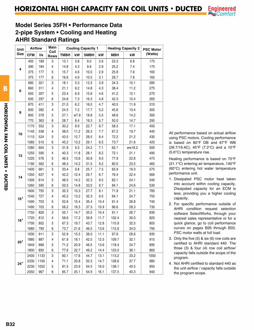
Unit Size
Airflow Main Coil
Rows
Cooling Capacity 1 Heating Capacity 2 PSC Motor (Watts)CFM l/s TMBH kW SMBH kW MBH kW
4
400 189 3 13.1 3.8 9.0 2.6 23.3 6.8 175390 184 4 14.8 4.3 9.8 2.9 25.2 7.4 170375 177 5 15.7 4.6 10.0 2.9 25.8 7.6 165375 177 6 16.6 4.9 10.5 3.1 26.7 7.8 165
6
680 321 3 18.1 5.3 13.3 3.9 34.3 10.1 280660 311 4 21.1 6.2 14.8 4.3 38.4 11.2 275650 307 5 23.4 6.9 15.8 4.6 41.2 12.1 270630 297 6 24.8 7.3 16.3 4.8 42.3 12.4 265
8
870 411 3 21.0 6.2 16.0 4.7 40.5 11.9 310830 392 4 24.5 7.2 17.7 5.2 45.6 13.4 305800 378 5 27.1 w7.9 18.8 5.5 48.6 14.2 300770 363 6 28.7 8.4 19.3 5.7 50.0 14.7 295
10
1170 552 3 30.2 8.9 22.7 6.7 58.3 17.1 4501140 538 4 38.0 11.2 26.3 7.7 67.2 19.7 4401110 524 5 43.5 12.7 28.5 8.4 72.2 21.2 4301080 510 6 45.2 13.2 29.1 8.5 73.7 21.6 420
12
1280 604 3 31.9 9.3 24.2 7.1 62.1 ww18.2 5001250 590 4 40.3 11.8 28.1 8.2 72.1 21.1 4901220 576 5 46.5 13.6 30.8 9.0 77.9 22.8 4751190 562 6 48.4 14.2 31.5 9.2 80.0 23.5 460
14
1400 661 3 33.4 9.8 25.7 7.5 65.9 19.3 5751350 637 4 42.2 12.4 29.7 8.7 76.4 22.4 5601300 614 5 48.5 14.2 32.3 9.5 82.1 24.1 5401260 595 6 50.5 14.8 33.0 9.7 84.1 24.6 530
163
1600 755 3 35.3 10.3 27.7 8.1 71.9 21.1 7851540 727 4 45.2 13.2 32.3 9.5 84.1 24.7 7551490 703 5 52.6 15.4 35.4 10.4 91.4 26.8 7401490 703 6 56.2 16.5 37.3 10.9 96.6 28.3 730
184
1750 826 3 50.1 14.7 35.5 10.4 91.1 26.7 8301720 812 4 58.6 17.2 39.8 11.7 102.4 30.0 8201700 802 5 67.3 19.7 43.7 12.8 110.9 32.5 8051680 793 6 73.7 21.6 46.5 13.6 115.9 34.0 795
204
1930 911 3 52.9 15.5 38.0 11.1 97.6 28.6 9351880 887 4 61.9 18.1 42.5 12.5 109.7 32.1 9151840 868 5 71.2 20.9 46.5 13.6 118.4 34.7 8951800 850 6 77.6 22.7 49.2 14.4 123.0 36.1 860
244
2400 1133 3 60.1 17.6 44.7 13.1 113.2 33.2 10002330 1100 4 71.1 20.8 50.3 14.7 128.6 37.7 9802230 1052 5 81.5 23.9 54.5 16.0 138.1 40.5 9502050 967 6 85.7 25.1 54.9 16.1 137.5 40.3 940
Model Series 35FH • Performance Data 2-pipe System • Cooling and HeatingAHRI Standard Ratings
All performance based on actual airflow using PSC motors. Cooling performance is based on 80°F DB and 67°F WB (26.7/19.4C), 45°F (7.2°C) and a 10°F (5.6°C) temperature rise.
Heating performance is based on 70°F (21.1°C) entering air temperature, 140°F (60°C) entering hot water temperature performance unit.
1. Dissipated PSC motor heat taken into account within cooling capacity. Dissipated capacity for an ECM is less, providing you a higher cooling capacity.
2. For specific performance outside of AHRI condition request selection software SelectWorks, through your nearest sales representative or for a quick glance, go to coil performance curves on pages B26 through B33. PSC motor watts at full load.
3. Only the five (5) & six (6) row coils are certified to AHRI standard 440. The three (3) & four (4) row coil airflow/capacity falls outside the scope of the program.
4. Not AHRI certified to standard 440 as the unit airflow / capacity falls outside the program scope.
HO
RIZ
ON
TAL FA
N C
OIL U
NITS •
DU
CTED
B
HORIZONTAL HIGH CAPACITY FAN COIL UNITS • DUCTED
B32
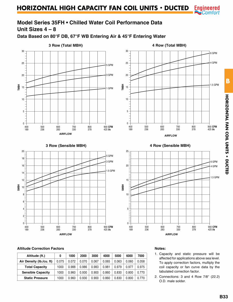
Model Series 35FH • Chilled Water Coil Performance DataUnit Sizes 4 – 8Data Based on 80°F DB, 67°F WB Entering Air & 45°F Entering Water
3 Row (Total MBH)
TMBH
400 500 600 700 800 900 CFM 189 236 283 330 378 425 l/s
30
25
20
15
10
5
0
5 GPM
3 GPM
1 GPM
AIRFLOW
4 Row (Total MBH)
TMBH
400 500 600 700 800 900 CFM 189 236 283 330 378 425 l/s
30
25
20
15
10
5
0
6 GPM
4 GPM
1.5 GPM
AIRFLOW
3 Row (Sensible MBH)
SMBH
400 500 600 700 800 900 CFM 189 236 283 330 378 425 l/s
20
18
16
14
12
10
8
6
4
2
0
5 GPM
3 GPM
1.5 GPM
4 Row (Sensible MBH)
SMBH
400 500 600 700 800 900 CFM 189 236 283 330 378 425 l/s
25
20
15
10
5
0
6 GPM
4 GPM
1.5 GPM
AIRFLOW AIRFLOW
Altitude Correction Factors Notes:1. Capacity and static pressure will be
affected for applications above sea level. To apply correction factors, multiply the coil capacity or fan curve data by the tabulated correction factor.
2. Connections: 3 and 4 Row 7/8" (22.2) O.D. male solder.
Altitude (ft.) 0 1000 2000 3000 4000 5000 6000 7000
Air Density (lb./cu. ft) 0.075 0.072 0.070 0.067 0.065 0.063 0.060 0.058
Total Capacity 1000 0.988 0.986 0.983 0.981 0.979 0.977 0.975
Sensible Capacity 1000 0.960 0.930 0.900 0.860 0.830 0.800 0.770
Static Pressure 1000 0.960 0.930 0.900 0.860 0.830 0.800 0.770
HO
RIZ
ON
TAL FA
N C
OIL U
NITS •
DU
CTED
B
HORIZONTAL HIGH CAPACITY FAN COIL UNITS • DUCTED
B33

Model Series 35FH • Chilled Water Coil Performance DataUnit Sizes 4 – 8Data Based on 80°F DB, 67°F WB Entering Air & 45°F Entering Water
5 Row (Total MBH)
TMBH
400 500 600 700 800 900 CFM 189 236 283 330 378 425 l/s
35
30
25
20
15
10
5
0
6 GPM
4 GPM
1.5 GPM
AIRFLOW
6 Row (Total MBH)
TMBH
400 500 600 700 800 900 CFM 189 236 283 330 378 425 l/s
40
35
30
25
20
15
10
5
0
7 GPM
4 GPM
2 GPM
1.5 GPM
AIRFLOW
5 Row (Sensible MBH)
SMBH
400 500 600 700 800 900 CFM 189 236 283 330 378 425 l/s
25
20
15
10
5
0
6 GPM
4 GPM
1.5 GPM
6 Row (Sensible MBH)
SMBH
400 500 600 700 800 900 CFM 189 236 283 330 378 425 l/s
25
20
15
10
5
0
7 GPM
4 GPM
2 GPM
1.5 GPM
AIRFLOW AIRFLOW
Notes:1. Capacity and static pressure will be
affected for applications above sea level. To apply correction factors, multiply the coil capacity or fan curve data by the tabulated correction factor.
2. Connections: 5 and 6 Row 7/8" (22.2) O.D. male solder.
Altitude (ft.) 0 1000 2000 3000 4000 5000 6000 7000
Air Density (lb./cu. ft) 0.075 0.072 0.070 0.067 0.065 0.063 0.060 0.058
Total Capacity 1000 0.988 0.986 0.983 0.981 0.979 0.977 0.975
Sensible Capacity 1000 0.960 0.930 0.900 0.860 0.830 0.800 0.770
Static Pressure 1000 0.960 0.930 0.900 0.860 0.830 0.800 0.770
Altitude Correction Factors
HO
RIZ
ON
TAL FA
N C
OIL U
NITS •
DU
CTED
B
HORIZONTAL HIGH CAPACITY FAN COIL UNITS • DUCTED
B34
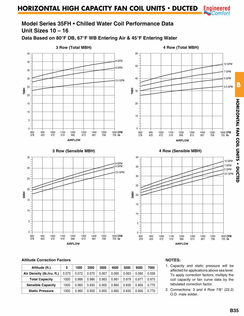
Model Series 35FH • Chilled Water Coil Performance DataUnit Sizes 10 – 16Data Based on 80°F DB, 67°F WB Entering Air & 45°F Entering Water
3 Row (Total MBH)
TMBH
45
40
35
30
25
20
15
10
5
0
8 GPM
6 GPM
3.5 GPM
800 900 1000 1100 1200 1300 1400 1500 1600 CFM378 425 472 519 566 613 661 708 755 l/s
AIRFLOW
4 Row (Total MBH)
TMBH
60
50
40
30
20
10
0
10 GPM
7 GPM
5 GPM
3.5 GPM
800 900 1000 1100 1200 1300 1400 1500 1600 CFM378 425 472 519 566 613 661 708 755 l/s
AIRFLOW
3 Row (Sensible MBH)
SMBH
35
30
25
20
15
10
5
0
8 GPM6 GPM
3.5 GPM
800 900 1000 1100 1200 1300 1400 1500 1600 CFM378 425 472 519 566 613 661 708 755 l/s
4 Row (Sensible MBH)
SMBH
40
35
30
25
20
15
10
5
0
10 GPM
7 GPM5 GPM
3.5 GPM
800 900 1000 1100 1200 1300 1400 1500 1600 CFM378 425 472 519 566 613 661 708 755 l/s
AIRFLOW AIRFLOW
Altitude Correction Factors NOTES:1. Capacity and static pressure will be
affected for applications above sea level. To apply correction factors, multiply the coil capacity or fan curve data by the tabulated correction factor.
2. Connections: 3 and 4 Row 7/8" (22.2) O.D. male solder.
Altitude (ft.) 0 1000 2000 3000 4000 5000 6000 7000
Air Density (lb./cu. ft.) 0.075 0.072 0.070 0.067 0.065 0.063 0.060 0.058
Total Capacity 1000 0.988 0.986 0.983 0.981 0.979 0.977 0.975
Sensible Capacity 1000 0.960 0.930 0.900 0.860 0.830 0.800 0.770
Static Pressure 1000 0.960 0.930 0.900 0.860 0.830 0.800 0.770
HO
RIZ
ON
TAL FA
N C
OIL U
NITS •
DU
CTED
B
HORIZONTAL HIGH CAPACITY FAN COIL UNITS • DUCTED
B35
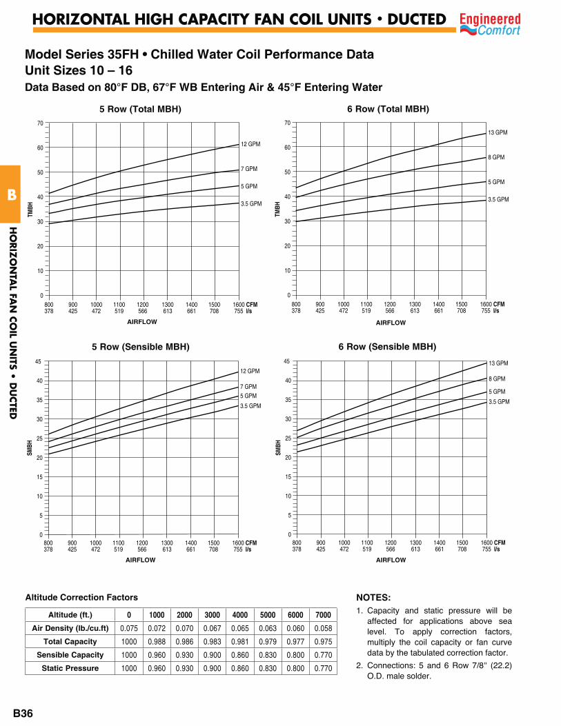
5 Row (Total MBH)
TMBH
70
60
50
40
30
20
10
0
12 GPM
7 GPM
5 GPM
3.5 GPM
800 900 1000 1100 1200 1300 1400 1500 1600 CFM378 425 472 519 566 613 661 708 755 l/s
AIRFLOW
6 Row (Total MBH)
TMBH
70
60
50
40
30
20
10
0
13 GPM
8 GPM
5 GPM
3.5 GPM
800 900 1000 1100 1200 1300 1400 1500 1600 CFM378 425 472 519 566 613 661 708 755 l/s
AIRFLOW
5 Row (Sensible MBH)
SMBH
45
40
35
30
25
20
15
10
5
0
12 GPM
7 GPM5 GPM
3.5 GPM
800 900 1000 1100 1200 1300 1400 1500 1600 CFM378 425 472 519 566 613 661 708 755 l/s
6 Row (Sensible MBH)
SMBH
45
40
35
30
25
20
15
10
5
0
13 GPM
8 GPM
5 GPM
3.5 GPM
800 900 1000 1100 1200 1300 1400 1500 1600 CFM378 425 472 519 566 613 661 708 755 l/s
AIRFLOW AIRFLOW
Model Series 35FH • Chilled Water Coil Performance DataUnit Sizes 10 – 16Data Based on 80°F DB, 67°F WB Entering Air & 45°F Entering Water
NOTES:1. Capacity and static pressure will be
affected for applications above sea level. To apply correction factors, multiply the coil capacity or fan curve data by the tabulated correction factor.
2. Connections: 5 and 6 Row 7/8" (22.2) O.D. male solder.
Altitude (ft.) 0 1000 2000 3000 4000 5000 6000 7000
Air Density (lb./cu.ft) 0.075 0.072 0.070 0.067 0.065 0.063 0.060 0.058
Total Capacity 1000 0.988 0.986 0.983 0.981 0.979 0.977 0.975
Sensible Capacity 1000 0.960 0.930 0.900 0.860 0.830 0.800 0.770
Static Pressure 1000 0.960 0.930 0.900 0.860 0.830 0.800 0.770
Altitude Correction Factors
HO
RIZ
ON
TAL FA
N C
OIL U
NITS •
DU
CTED
B
HORIZONTAL HIGH CAPACITY FAN COIL UNITS • DUCTED
B36
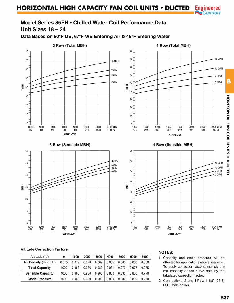
3 Row (Total MBH)
TMBH
80
70
60
50
40
30
20
10
0
14 GPM
9 GPM
7 GPM
5 GPM
1000 1200 1400 1600 1800 2000 2200 2400 CFM 472 566 661 755 849 944 1038 1133 l/s
AIRFLOW
4 Row (Total MBH)
TMBH
90
80
70
60
50
40
30
20
10
0
16 GPM
10 GPM
7 GPM
5 GPM
1000 1200 1400 1600 1800 2000 2200 2400 CFM 472 566 661 755 849 944 1038 1133 l/s
AIRFLOW
3 Row (Sensible MBH)
SMBH
60
50
40
30
20
10
0
14 GPM
9 GPM7 GPM5 GPM
1000 1200 1400 1600 1800 2000 2200 2400 CFM 472 566 661 755 849 944 1038 1133 l/s
4 Row (Sensible MBH)
SMBH
70
60
50
40
30
20
10
0
16 GPM
10 GPM7 GPM5 GPM
1000 1200 1400 1600 1800 2000 2200 2400 CFM 472 566 661 755 849 944 1038 1133 l/s
AIRFLOW AIRFLOW
NOTES:1. Capacity and static pressure will be
affected for applications above sea level. To apply correction factors, multiply the coil capacity or fan curve data by the tabulated correction factor.
2. Connections: 3 and 4 Row 1 1/8" (28.6) O.D. male solder.
Model Series 35FH • Chilled Water Coil Performance DataUnit Sizes 18 – 24Data Based on 80°F DB, 67°F WB Entering Air & 45°F Entering Water
Altitude Correction Factors
Altitude (ft.) 0 1000 2000 3000 4000 5000 6000 7000
Air Density (lb./cu.ft) 0.075 0.072 0.070 0.067 0.065 0.063 0.060 0.058
Total Capacity 1000 0.988 0.986 0.983 0.981 0.979 0.977 0.975
Sensible Capacity 1000 0.960 0.930 0.900 0.860 0.830 0.800 0.770
Static Pressure 1000 0.960 0.930 0.900 0.860 0.830 0.800 0.770
HO
RIZ
ON
TAL FA
N C
OIL U
NITS •
DU
CTED
B
HORIZONTAL HIGH CAPACITY FAN COIL UNITS • DUCTED
B37
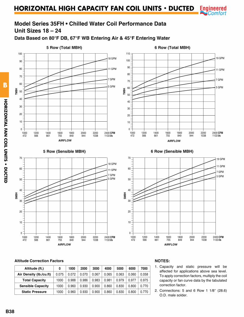
Model Series 35FH • Chilled Water Coil Performance DataUnit Sizes 18 – 24Data Based on 80°F DB, 67°F WB Entering Air & 45°F Entering Water
5 Row (Total MBH)
TMBH
100
90
80
70
60
50
40
30
20
10
0
18 GPM
11 GPM
7 GPM
5 GPM
1000 1200 1400 1600 1800 2000 2200 2400 CFM 472 566 661 755 849 944 1038 1133 l/s
AIRFLOW
6 Row (Total MBH)
TMBH
110
100
90
80
70
60
50
40
30
20
10
0
19 GPM
11 GPM
7 GPM
5 GPM
1000 1200 1400 1600 1800 2000 2200 2400 CFM 472 566 661 755 849 944 1038 1133 l/s
AIRFLOW
5 Row (Sensible MBH)
SMBH
70
60
50
40
30
20
10
0
18 GPM
11 GPM
7 GPM5 GPM
1000 1200 1400 1600 1800 2000 2200 2400 CFM 472 566 661 755 849 944 1038 1133 l/s
6 Row (Sensible MBH)
SMBH
70
60
50
40
30
20
10
0
19 GPM
11 GPM
7 GPM
5 GPM
1000 1200 1400 1600 1800 2000 2200 2400 CFM 472 566 661 755 849 944 1038 1133 l/s
AIRFLOW AIRFLOW
NOTES:1. Capacity and static pressure will be
affected for applications above sea level. To apply correction factors, multiply the coil capacity or fan curve data by the tabulated correction factor.
2. Connections: 5 and 6 Row 1 1/8" (28.6) O.D. male solder.
Altitude Correction Factors
Altitude (ft.) 0 1000 2000 3000 4000 5000 6000 7000
Air Density (lb./cu.ft) 0.075 0.072 0.070 0.067 0.065 0.063 0.060 0.058
Total Capacity 1000 0.988 0.986 0.983 0.981 0.979 0.977 0.975
Sensible Capacity 1000 0.960 0.930 0.900 0.860 0.830 0.800 0.770
Static Pressure 1000 0.960 0.930 0.900 0.860 0.830 0.800 0.770
HO
RIZ
ON
TAL FA
N C
OIL U
NITS •
DU
CTED
B
HORIZONTAL HIGH CAPACITY FAN COIL UNITS • DUCTED
B38
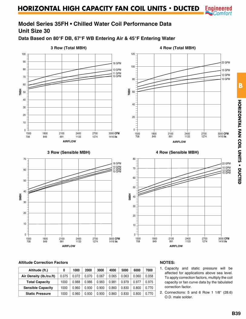
Model Series 35FH • Chilled Water Coil Performance DataUnit Size 30Data Based on 80°F DB, 67°F WB Entering Air & 45°F Entering Water
3 Row (Total MBH)
TMBH
100
90
80
70
60
50
40
30
20
10
0
18 GPM
13 GPM11 GPM10 GPM
1500 1800 2100 2400 2700 3000 CFM708 849 991 1133 1274 1416 l/s
AIRFLOW
4 Row (Total MBH)
TMBH
120
100
80
60
40
20
0
22 GPM
15 GPM
12 GPM10 GPM
1500 1800 2100 2400 2700 3000 CFM 708 849 991 1133 1274 1416 l/s
AIRFLOW
3 Row (Sensible MBH)
SMBH
70
60
50
40
30
20
10
0
18 GPM13 GPM11 GPM10 GPM
1500 1800 2100 2400 2700 3000 CFM 708 849 991 1133 1274 1416 l/s
4 Row (Sensible MBH)
SMBH
80
70
60
50
40
30
20
10
0
22 GPM
15 GPM12 GPM10 GPM
1500 1800 2100 2400 2700 3000 CFM 708 849 991 1133 1274 1416 l/s
AIRFLOW AIRFLOW
NOTES:1. Capacity and static pressure will be
affected for applications above sea level. To apply correction factors, multiply the coil capacity or fan curve data by the tabulated correction factor.
2. Connections: 5 and 6 Row 1 1/8" (28.6) O.D. male solder.
Altitude Correction Factors
Altitude (ft.) 0 1000 2000 3000 4000 5000 6000 7000
Air Density (lb./cu.ft) 0.075 0.072 0.070 0.067 0.065 0.063 0.060 0.058
Total Capacity 1000 0.988 0.986 0.983 0.981 0.979 0.977 0.975
Sensible Capacity 1000 0.960 0.930 0.900 0.860 0.830 0.800 0.770
Static Pressure 1000 0.960 0.930 0.900 0.860 0.830 0.800 0.770
HO
RIZ
ON
TAL FA
N C
OIL U
NITS •
DU
CTED
B
HORIZONTAL HIGH CAPACITY FAN COIL UNITS • DUCTED
B39
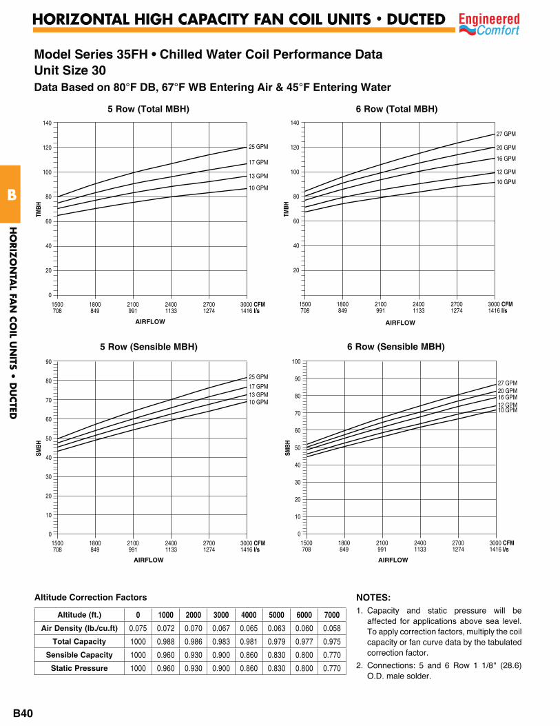
Model Series 35FH • Chilled Water Coil Performance DataUnit Size 30Data Based on 80°F DB, 67°F WB Entering Air & 45°F Entering Water
5 Row (Total MBH)
TMBH
140
120
100
80
60
40
20
0
25 GPM
17 GPM
13 GPM
10 GPM
1500 1800 2100 2400 2700 3000 CFM 708 849 991 1133 1274 1416 l/s
AIRFLOW
6 Row (Total MBH)
TMBH
140
120
100
80
60
40
20
27 GPM
20 GPM
16 GPM
12 GPM
10 GPM
1500 1800 2100 2400 2700 3000 CFM 708 849 991 1133 1274 1416 l/s
AIRFLOW
5 Row (Sensible MBH)
SMBH
90
80
70
60
50
40
30
20
10
0
25 GPM
17 GPM13 GPM10 GPM
1500 1800 2100 2400 2700 3000 CFM 708 849 991 1133 1274 1416 l/s
6 Row (Sensible MBH)
SMBH
100
90
80
70
60
50
40
30
20
10
0
27 GPM20 GPM16 GPM12 GPM10 GPM
1500 1800 2100 2400 2700 3000 CFM 708 849 991 1133 1274 1416 l/s
AIRFLOW AIRFLOW
NOTES:1. Capacity and static pressure will be
affected for applications above sea level. To apply correction factors, multiply the coil capacity or fan curve data by the tabulated correction factor.
2. Connections: 5 and 6 Row 1 1/8" (28.6) O.D. male solder.
Altitude Correction Factors
Altitude (ft.) 0 1000 2000 3000 4000 5000 6000 7000
Air Density (lb./cu.ft) 0.075 0.072 0.070 0.067 0.065 0.063 0.060 0.058
Total Capacity 1000 0.988 0.986 0.983 0.981 0.979 0.977 0.975
Sensible Capacity 1000 0.960 0.930 0.900 0.860 0.830 0.800 0.770
Static Pressure 1000 0.960 0.930 0.900 0.860 0.830 0.800 0.770
HO
RIZ
ON
TAL FA
N C
OIL U
NITS •
DU
CTED
B
HORIZONTAL HIGH CAPACITY FAN COIL UNITS • DUCTED
B40

Model Series 35FH • Chilled Water Coil Performance DataUnit Size 40Data Based on 80°F DB, 67°F WB Entering Air & 45°F Entering Water
3 Row (Total MBH)
TMBH
120
100
80
60
40
20
0
23 GPM
16 GPM
12 GPM
10 GPM
2000 2500 3000 3500 4000 CFM 944 1180 1416 1652 1888 l/s
AIRFLOW
4 Row (Total MBH)
TMBH
160
140
120
100
80
60
40
20
0
27 GPM
20 GPM
16 GPM
12 GPM10 GPM
2000 2500 3000 3500 4000 CFM 944 1180 1416 1652 1888 l/s
AIRFLOW
3 Row (Sensible MBH)
SMBH
90
80
70
60
50
40
30
20
10
0
23 GPM16 GPM12 GPM10 GPM
2000 2500 3000 3500 4000 CFM 944 1180 1416 1652 1888 l/s
4 Row (Sensible MBH)
SMBH
120
100
80
60
40
20
0
27 GPM20 GPM16 GPM12 GPM10 GPM
2000 2500 3000 3500 4000 CFM 944 1180 1416 1652 1888 l/s
AIRFLOW AIRFLOW
NOTES:1. Capacity and static pressure will be
affected for applications above sea level. To apply correction factors, multiply the coil capacity or fan curve data by the tabulated correction factor.
2. Connections: 5 and 6 Row 1 1/8" (28.6) O.D. male solder.
Altitude Correction Factors
Altitude (ft.) 0 1000 2000 3000 4000 5000 6000 7000
Air Density (lb./cu.ft) 0.075 0.072 0.070 0.067 0.065 0.063 0.060 0.058
Total Capacity 1000 0.988 0.986 0.983 0.981 0.979 0.977 0.975
Sensible Capacity 1000 0.960 0.930 0.900 0.860 0.830 0.800 0.770
Static Pressure 1000 0.960 0.930 0.900 0.860 0.830 0.800 0.770
HO
RIZ
ON
TAL FA
N C
OIL U
NITS •
DU
CTED
B
HORIZONTAL HIGH CAPACITY FAN COIL UNITS • DUCTED
B41
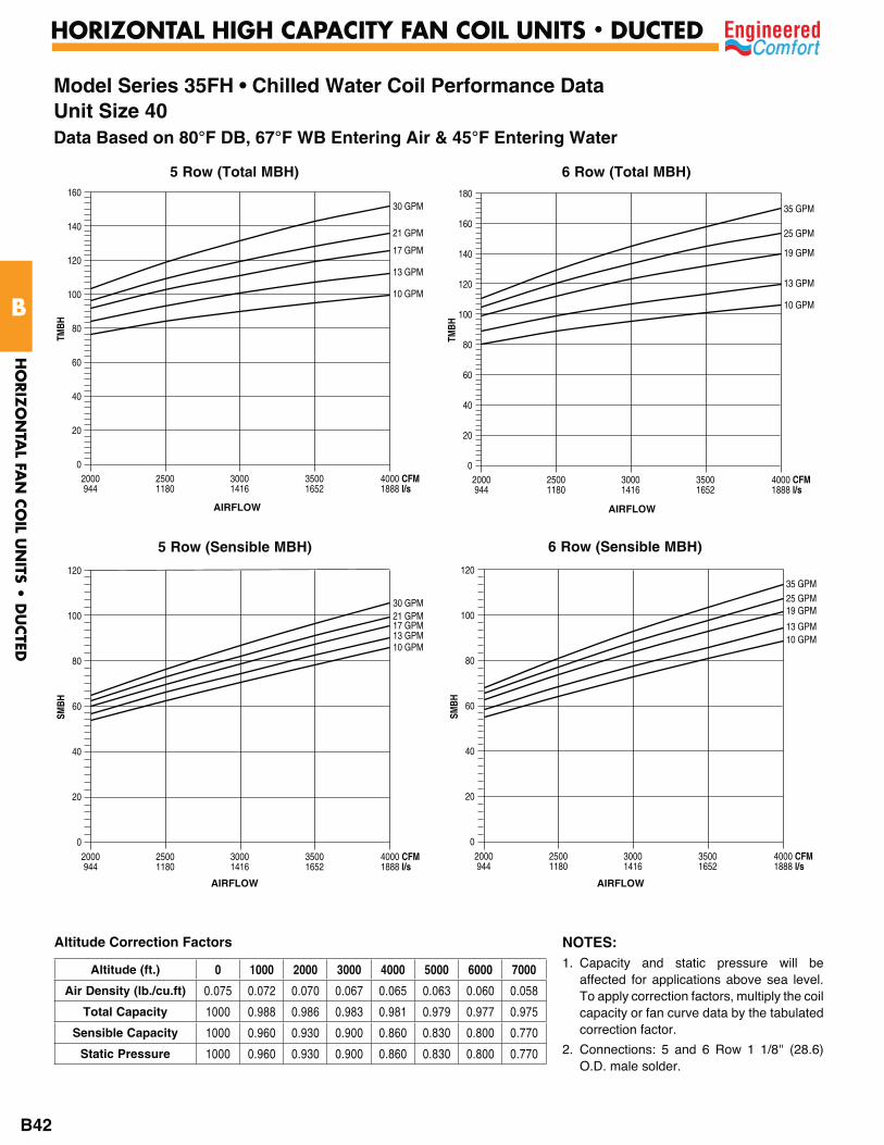
Model Series 35FH • Chilled Water Coil Performance DataUnit Size 40Data Based on 80°F DB, 67°F WB Entering Air & 45°F Entering Water
5 Row (Total MBH)
TMBH
160
140
120
100
80
60
40
20
0
30 GPM
21 GPM
17 GPM
13 GPM
10 GPM
2000 2500 3000 3500 4000 CFM 944 1180 1416 1652 1888 l/s
AIRFLOW
6 Row (Total MBH)
TMBH
180
160
140
120
100
80
60
40
20
0
35 GPM
25 GPM
19 GPM
13 GPM
10 GPM
2000 2500 3000 3500 4000 CFM 944 1180 1416 1652 1888 l/s
AIRFLOW
5 Row (Sensible MBH)
SMBH
120
100
80
60
40
20
0
30 GPM21 GPM17 GPM13 GPM10 GPM
2000 2500 3000 3500 4000 CFM 944 1180 1416 1652 1888 l/s
6 Row (Sensible MBH)
SMBH
120
100
80
60
40
20
0
35 GPM25 GPM19 GPM
13 GPM10 GPM
2000 2500 3000 3500 4000 CFM 944 1180 1416 1652 1888 l/s
AIRFLOW AIRFLOW
NOTES:1. Capacity and static pressure will be
affected for applications above sea level. To apply correction factors, multiply the coil capacity or fan curve data by the tabulated correction factor.
2. Connections: 5 and 6 Row 1 1/8" (28.6) O.D. male solder.
Altitude Correction Factors
Altitude (ft.) 0 1000 2000 3000 4000 5000 6000 7000
Air Density (lb./cu.ft) 0.075 0.072 0.070 0.067 0.065 0.063 0.060 0.058
Total Capacity 1000 0.988 0.986 0.983 0.981 0.979 0.977 0.975
Sensible Capacity 1000 0.960 0.930 0.900 0.860 0.830 0.800 0.770
Static Pressure 1000 0.960 0.930 0.900 0.860 0.830 0.800 0.770
HO
RIZ
ON
TAL FA
N C
OIL U
NITS •
DU
CTED
B
HORIZONTAL HIGH CAPACITY FAN COIL UNITS • DUCTED
B42
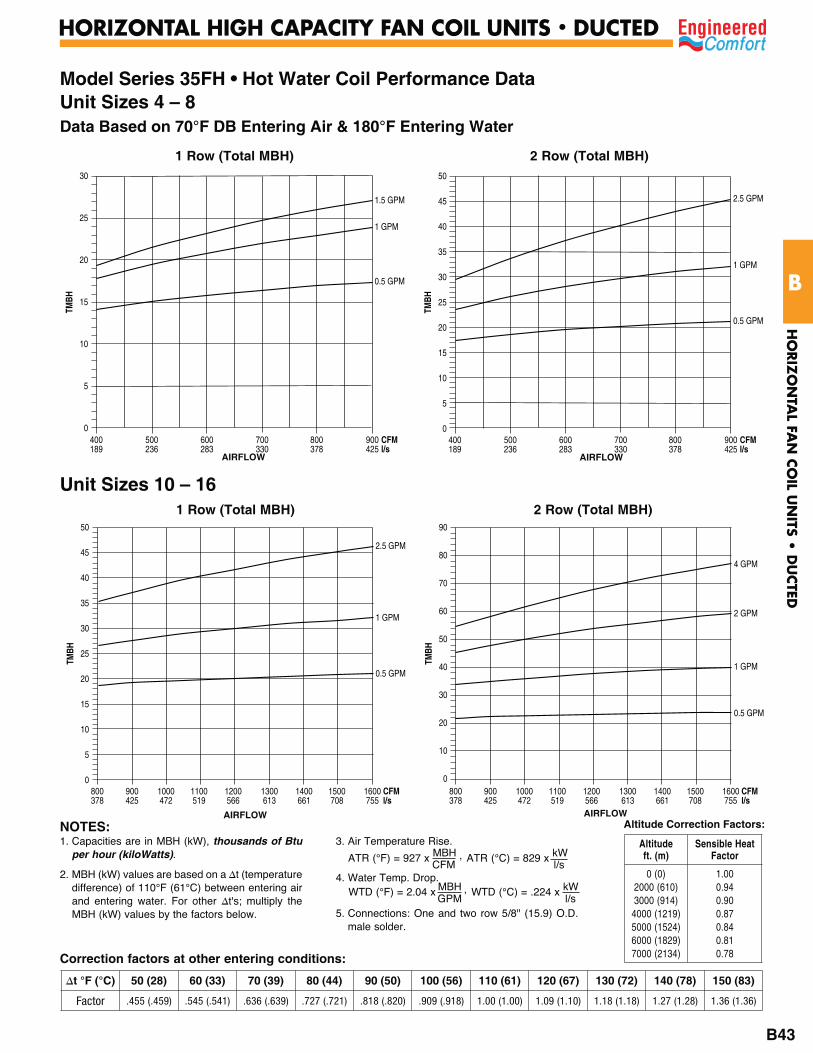
Model Series 35FH • Hot Water Coil Performance DataUnit Sizes 4 – 8Data Based on 70°F DB Entering Air & 180°F Entering Water
1 Row (Total MBH)
TMBH
400 500 600 700 800 900 CFM 189 236 283 330 378 425 l/s
30
25
20
15
10
5
0
1.5 GPM
1 GPM
0.5 GPM
AIRFLOW
2 Row (Total MBH)
TMBH
400 500 600 700 800 900 CFM 189 236 283 330 378 425 l/s
50
45
40
35
30
25
20
15
10
5
0
2.5 GPM
1 GPM
0.5 GPM
AIRFLOW
AIRFLOW AIRFLOW
1 Row (Total MBH)
TMBH
50
45
40
35
30
25
20
15
10
5
0
2.5 GPM
1 GPM
0.5 GPM
800 900 1000 1100 1200 1300 1400 1500 1600 CFM378 425 472 519 566 613 661 708 755 l/s
Unit Sizes 10 – 16
TMBH
90
80
70
60
50
40
30
20
10
0
4 GPM
2 GPM
1 GPM
0.5 GPM
800 900 1000 1100 1200 1300 1400 1500 1600 CFM378 425 472 519 566 613 661 708 755 l/s
2 Row (Total MBH)
Correction factors at other entering conditions:
1. Capacities are in MBH (kW), thousands of Btu per hour (kiloWatts).
2. MBH (kW) values are based on a t (temperature difference) of 110°F (61°C) between entering air and entering water. For other t's; multiply the MBH (kW) values by the factors below.
3. Air Temperature Rise.
4. Water Temp. Drop.
5. Connections: One and two row 5/8" (15.9) O.D. male solder.
ATR (°C) = 829 x kW l/s
ATR (°F) = 927 x MBH , CFM
WTD (°C) = .224 x kW l/s
WTD (°F) = 2.04 x MBH , GPM
NOTES:
50 (28) 60 (33) 70 (39) 80 (44) 90 (50) 100 (56) 110 (61) 120 (67) 130 (72) 140 (78) 150 (83)
Factor .455 (.459) .545 (.541) .636 (.639) .727 (.721) .818 (.820) .909 (.918) 1.00 (1.00) 1.09 (1.10) 1.18 (1.18) 1.27 (1.28) 1.36 (1.36)
Altitude Correction Factors:
Altitude ft. (m)
Sensible Heat Factor
0 (0)2000 (610) 3000 (914)
4000 (1219) 5000 (1524) 6000 (1829) 7000 (2134)
1.00 0.94 0.90 0.87 0.84 0.81 0.78
HO
RIZ
ON
TAL FA
N C
OIL U
NITS •
DU
CTED
B
HORIZONTAL HIGH CAPACITY FAN COIL UNITS • DUCTED
B43

Model Series 35FH • Hot Water Coil Performance Data Unit Sizes 18 – 24Data Based on 70°F DB Entering Air & 180°F Entering Water
AIRFLOW
1 Row (Total MBH)
TMBH
80
70
60
50
40
30
20
10
0
3.5 GPM
2 GPM
1 GPM
0.5 GPM
1000 1200 1400 1600 1800 2000 2200 2400 CFM 472 566 661 755 849 944 1038 1133 l/s
2 Row (Total MBH)
TMBH
140
120
100
80
60
40
20
0
4 GPM
3 GPM
2 GPM
1 GPM
0.5 GPM
1000 1200 1400 1600 1800 2000 2200 2400 CFM 472 566 661 755 849 944 1038 1133 l/s
AIRFLOW
Correction factors at other entering conditions:
1. Capacities are in MBH (kW), thousands of Btu per hour (kiloWatts).
2. MBH (kW) values are based on a t (temperature difference) of 110°F (61°C) between entering air and entering water. For other t's; multiply the MBH (kW) values by the factors below.
3. Air Temperature Rise.
4. Water Temp. Drop.
5. Connections: One and two row 5/8" (15.9) O.D. male solder.
ATR (°C) = 829 x kW l/s
ATR (°F) = 927 x MBH , CFM
WTD (°C) = .224 x kW l/s
WTD (°F) = 2.04 x MBH , GPM
NOTES:
50 (28) 60 (33) 70 (39) 80 (44) 90 (50) 100 (56) 110 (61) 120 (67) 130 (72) 140 (78) 150 (83)
Factor .455 (.459) .545 (.541) .636 (.639) .727 (.721) .818 (.820) .909 (.918) 1.00 (1.00) 1.09 (1.10) 1.18 (1.18) 1.27 (1.28) 1.36 (1.36)
Altitude Correction Factors:
Altitude ft. (m)
Sensible Heat Factor
0 (0)2000 (610) 3000 (914)
4000 (1219) 5000 (1524) 6000 (1829) 7000 (2134)
1.00 0.94 0.90 0.87 0.84 0.81 0.78
Unit Size 301 Row (Total MBH)
TMBH
100
90
80
70
60
50
40
30
20
10
0
5 GPM
3 GPM
2 GPM
1 GPM
0.5 GPM
1500 1800 2100 2400 2700 3000 CFM 708 849 991 1133 1274 1416 l/s
2 Row (Total MBH)
TMBH
160
140
120
100
80
60
40
20
0
8 GPM
6 GPM
5 GPM
4 GPM
3 GPM
1500 1800 2100 2400 2700 3000 CFM 708 849 991 1133 1274 1416 l/s
HO
RIZ
ON
TAL FA
N C
OIL U
NITS •
DU
CTED
B
HORIZONTAL HIGH CAPACITY FAN COIL UNITS • DUCTED
B44
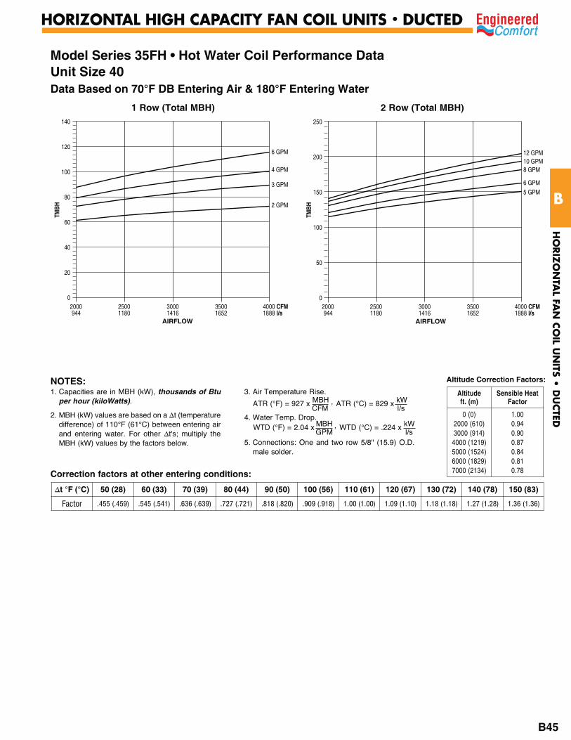
Model Series 35FH • Hot Water Coil Performance DataUnit Size 40Data Based on 70°F DB Entering Air & 180°F Entering Water
1 Row (Total MBH)
TMBH
140
120
100
80
60
40
20
0
6 GPM
4 GPM
3 GPM
2 GPM
2000 2500 3000 3500 4000 CFM 944 1180 1416 1652 1888 l/s
AIRFLOW
2 Row (Total MBH)
TMBH
250
200
150
100
50
0
12 GPM10 GPM8 GPM
6 GPM5 GPM
2000 2500 3000 3500 4000 CFM 944 1180 1416 1652 1888 l/s
AIRFLOW
Correction factors at other entering conditions:
1. Capacities are in MBH (kW), thousands of Btu per hour (kiloWatts).
2. MBH (kW) values are based on a t (temperature difference) of 110°F (61°C) between entering air and entering water. For other t's; multiply the MBH (kW) values by the factors below.
3. Air Temperature Rise.
4. Water Temp. Drop.
5. Connections: One and two row 5/8" (15.9) O.D. male solder.
ATR (°C) = 829 x kW l/s
ATR (°F) = 927 x MBH , CFM
WTD (°C) = .224 x kW l/s
WTD (°F) = 2.04 x MBH , GPM
NOTES:
50 (28) 60 (33) 70 (39) 80 (44) 90 (50) 100 (56) 110 (61) 120 (67) 130 (72) 140 (78) 150 (83)
Factor .455 (.459) .545 (.541) .636 (.639) .727 (.721) .818 (.820) .909 (.918) 1.00 (1.00) 1.09 (1.10) 1.18 (1.18) 1.27 (1.28) 1.36 (1.36)
Altitude Correction Factors:
Altitude ft. (m)
Sensible Heat Factor
0 (0)2000 (610) 3000 (914)
4000 (1219) 5000 (1524) 6000 (1829) 7000 (2134)
1.00 0.94 0.90 0.87 0.84 0.81 0.78
HO
RIZ
ON
TAL FA
N C
OIL U
NITS •
DU
CTED
B
HORIZONTAL HIGH CAPACITY FAN COIL UNITS • DUCTED
B45
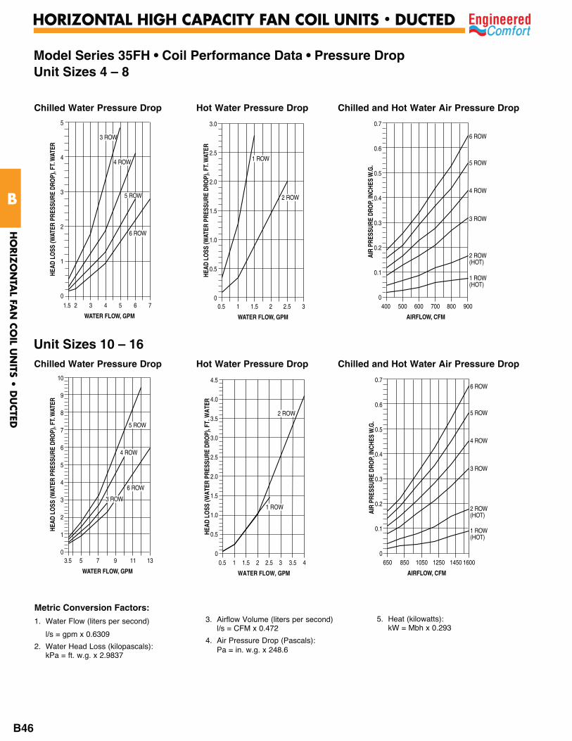
Metric Conversion Factors:1. Water Flow (liters per second)
l/s = gpm x 0.6309
2. Water Head Loss (kilopascals): kPa = ft. w.g. x 2.9837
3. Airflow Volume (liters per second) l/s = CFM x 0.472
4. Air Pressure Drop (Pascals): Pa = in. w.g. x 248.6
5. Heat (kilowatts): kW = Mbh x 0.293
Model Series 35FH • Coil Performance Data • Pressure DropUnit Sizes 4 – 8
1.5 2 3 4 5 6 7
WATER FLOW, GPM
5
4
3
2
1
0
3 ROW
4 ROW
5 ROW
6 ROW
HEAD
LO
SS (W
ATER
PRE
SSUR
E DR
OP)
, FT.
WAT
ER
Chilled Water Pressure Drop
HEAD
LO
SS (W
ATER
PRE
SSUR
E DR
OP)
, FT.
WAT
ER
0.5 1 1.5 2 2.5 3
WATER FLOW, GPM
3.0
2.5
2.0
1.5
1.0
0.5
0
1 ROW
2 ROW
Hot Water Pressure Drop
400 500 600 700 800 900
0.7
0.6
0.5
0.4
0.3
0.2
0.1
0
6 ROW
1 ROW(HOT)
5 ROW
3 ROW
4 ROW
2 ROW(HOT)
AIR
PRES
SURE
DRO
P, IN
CHES
W.G
.
AIRFLOW, CFM
Chilled and Hot Water Air Pressure Drop
3.5 5 7 9 11 13
WATER FLOW, GPM
10
9
8
7
6
5
4
3
2
1
0
3 ROW
4 ROW
5 ROW
6 ROW
HEAD
LO
SS (W
ATER
PRE
SSUR
E DR
OP)
, FT.
WAT
ER
Chilled Water Pressure Drop
Unit Sizes 10 – 16
0.5 1 1.5 2 2.5 3 3.5 4
WATER FLOW, GPM
4.5
4.0
3.5
3.0
2.5
2.0
1.5
1.0
0.5
0
1 ROW
2 ROW
HEAD
LO
SS (W
ATER
PRE
SSUR
E DR
OP)
, FT.
WAT
ER
Hot Water Pressure Drop
650 850 1050 1250 1450 1600
0.7
0.6
0.5
0.4
0.3
0.2
0.1
0
6 ROW
1 ROW(HOT)
5 ROW
3 ROW
4 ROW
2 ROW(HOT)AI
R PR
ESSU
RE D
ROP,
INCH
ES W
.G.
AIRFLOW, CFM
Chilled and Hot Water Air Pressure Drop
HO
RIZ
ON
TAL FA
N C
OIL U
NITS •
DU
CTED
B
HORIZONTAL HIGH CAPACITY FAN COIL UNITS • DUCTED
B46

Metric Conversion Factors:
1. Water Flow (liters per second)
l/s = gpm x 0.6309
2. Water Head Loss (kilopascals): kPa = ft. w.g. x 2.9837
3. Airflow Volume (liters per second) l/s = CFM x 0.472
4. Air Pressure Drop (Pascals): Pa = in. w.g. x 248.6
5. Heat (kilowatts): kW = Mbh x 0.293
Model Series 35FH • Coil Performance Data • Pressure DropUnit Sizes 18 – 24
5 7 9 11 13 15 17 19
WATER FLOW, GPM
18
16
14
12
10
8
6
4
2
1
3 ROW
4 ROW
5 ROW
6 ROW
HEAD
LO
SS (W
ATER
PRE
SSUR
E DR
OP)
, FT.
WAT
ER
Chilled Water Pressure Drop Hot Water Pressure Drop
1000 1300 1600 1900 2200 2400
0.7
0.6
0.5
0.4
0.3
0.2
0.1
0
6 ROW
1 ROW(HOT)
5 ROW
3 ROW
4 ROW
2 ROW(HOT)AI
R PR
ESSU
RE D
ROP,
INCH
ES W
.G.
AIRFLOW, CFM
Chilled and Hot Water Air Pressure Drop
0.5 1 2 3 4 5 6
WATER FLOW, GPM
7
6
5
4
3
2
1
0
1 ROW
2 ROW
HEAD
LO
SS (W
ATER
PRE
SSUR
E DR
OP)
, FT.
WAT
ER
Unit Size 30
10 15 20 25 30
WATER FLOW, GPM
10
9
8
7
6
5
4
3
2
1
0
3 ROW
HEAD
LO
SS (W
ATER
PRE
SSUR
E DR
OP)
, FT.
WAT
ER
4 ROW5 ROW
6 ROW
Chilled Water Pressure Drop Hot Water Pressure Drop
1500 1800 2100 2400 2700 3000
0.7
0.6
0.5
0.4
0.3
0.2
0.1
0
6 ROW
1 ROW(HOT)
5 ROW
3 ROW
4 ROW
2 ROW(HOT)
AIR
PRES
SURE
DRO
P, IN
CHES
W.G
.
AIRFLOW, CFM
Chilled and Hot Water Air Pressure Drop
0.5 1 2 3 4 5 6 7 8 9
WATER FLOW, GPM
2.5
2.0
1.5
1.0
0.5
0
2 ROW
HEAD
LO
SS (W
ATER
PRE
SSUR
E DR
OP)
, FT.
WAT
ER
1 ROW
HO
RIZ
ON
TAL FA
N C
OIL U
NITS •
DU
CTED
B
HORIZONTAL HIGH CAPACITY FAN COIL UNITS • DUCTED
B47
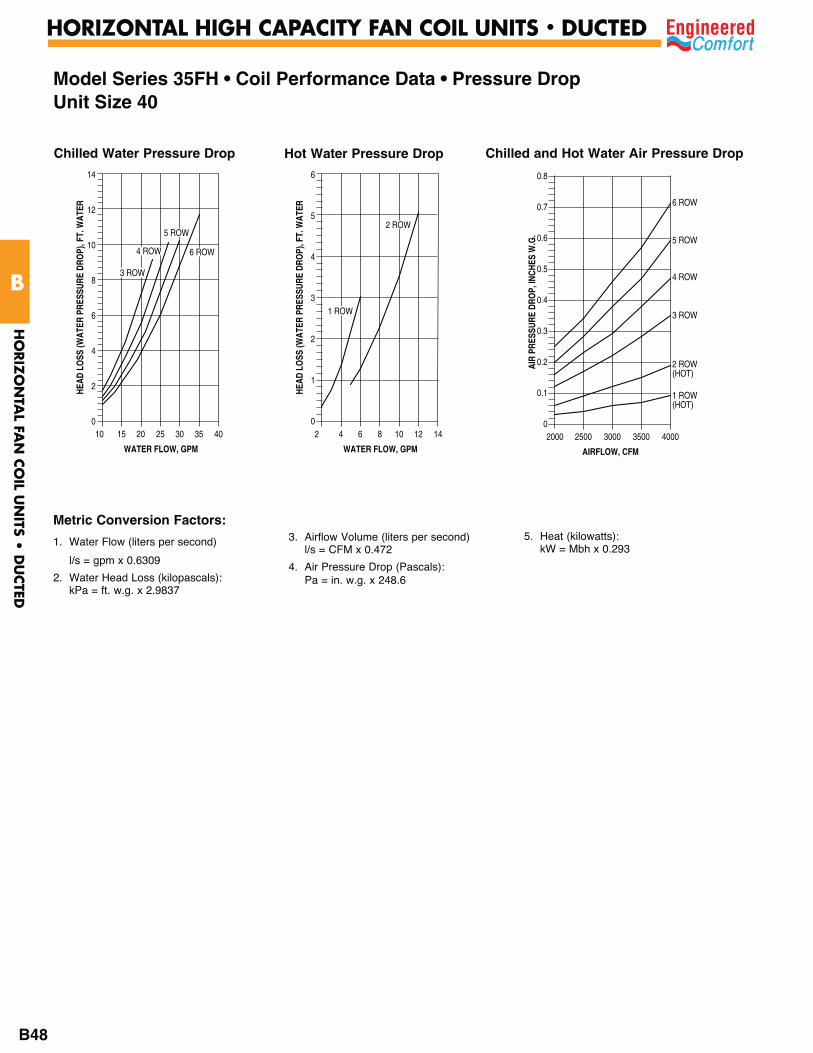
Metric Conversion Factors:
1. Water Flow (liters per second)
l/s = gpm x 0.6309
2. Water Head Loss (kilopascals): kPa = ft. w.g. x 2.9837
3. Airflow Volume (liters per second) l/s = CFM x 0.472
4. Air Pressure Drop (Pascals): Pa = in. w.g. x 248.6
5. Heat (kilowatts): kW = Mbh x 0.293
Model Series 35FH • Coil Performance Data • Pressure DropUnit Size 40
10 15 20 25 30 35 40
WATER FLOW, GPM
14
12
10
8
6
4
2
0
HEAD
LO
SS (W
ATER
PRE
SSUR
E DR
OP)
, FT.
WAT
ER
3 ROW
5 ROW
6 ROW4 ROW
Chilled Water Pressure Drop Hot Water Pressure Drop
2000 2500 3000 3500 4000
0.8
0.7
0.6
0.5
0.4
0.3
0.2
0.1
0
6 ROW
1 ROW(HOT)
5 ROW
3 ROW
4 ROW
2 ROW(HOT)
AIR
PRES
SURE
DRO
P, IN
CHES
W.G
.
AIRFLOW, CFM
Chilled and Hot Water Air Pressure Drop
2 4 6 8 10 12 14
WATER FLOW, GPM
6
5
4
3
2
1
0
1 ROWHE
AD L
OSS
(WAT
ER P
RESS
URE
DRO
P), F
T. W
ATER
2 ROW
HO
RIZ
ON
TAL FA
N C
OIL U
NITS •
DU
CTED
B
HORIZONTAL HIGH CAPACITY FAN COIL UNITS • DUCTED
B48
HO
RIZ
ON
TAL FA
N C
OIL U
NITS •
DU
CTED
B
HORIZONTAL HIGH CAPACITY FAN COIL UNITS • DUCTED
B49
Model Series 35FH • Suggested Specifications
1. General Furnish and install Engineered Comfort Model 35FH Series High
Performance Horizontal Fan Coil Units where indicated on the plans and in the specifications.
2. Constructiona.All units shall be Direct Drive – Draw Through configuration
and completely factory assembled, tested and shipped as one piece. All units shall be capable of meeting or exceeding the scheduled capacities for cooling, heating and air delivery. All unit dimensions, for each model and size, shall be considered maximums. Units shall be UL or ETL, listed in compliance with UL 1995, and be certified as complying with the latest edition of AHRI Standard 440. Must meet the requirements of NFPA 90A and UL 181.
b. All unit chassis shall be fabricated of heavy gauge galvanized steel panels able to meet 125-hour salt spray test per ASTM B-117. 18 ga. (1.31) galvanized steel channel frame. All panels surrounding the coil shall be insulated with 3/4" (19) thick closed cell fiber-free and rated for air velocity of 6000 f.p.m. Insulation must meet all requirements of ASTM C1071 (including C665), UL 181 for erosion, and carry a 25/50 rating for flame spread/smoke developed per ASTM E-84, UL 723 and NFPA 90A. All other panels, surrounding the units, must also be acoustically and thermally insulated with a minimum of 3/4" (19) insulation with dual density insulation fiber glass insulation where all exposed edges are coated to prevent air erosion.
c. Unit cabinet shall have side and bottom full size access panels for ease of maintenance and service and motor blower removal. Access panels shall be attached to casing with screws.
Optional• Aluminum foil-faced insulation (steri-liner), meets ASTM
Standards C-665 and C-1136 for biological growth in insulation. All exposed edges shall be sealed to prevent any fibers from reaching the air stream.
• Close cell fiber-free liner. Insulation shall conform to UL 181 for erosion and NFPA 90A for fire, smoke and melting, and comply with a 25/50 Flame Spread and Smoke Developed Index per ASTM E-84 or UL 723. Additionally, insulation shall comply with Antimicrobial Performance Rating of 0, no observed growth, per ASTM G-21.
• Perforated metal with steri-liner.4. Casing leakage shall not exceed 2% of rated airflow @ .5" w.g. (125
Pa). 5. Unit shall be draw through type with fan dynamically balanced,
forwardly curved; DWDI centrifugal type constructed of 18 gauge (1.31) zinc coated galvanized steel for corrosion resistance. The fan assembly shall be easily removable for servicing the motor and blower at, or away from the unit. The entire fan assembly shall be able to come out of the unit by removing four nuts per fan and disconnecting the motor(s) wires.
6. Motor shall be direct drive, isolated from blower and fan housing in at least four (4) locations with rubber isolators to eliminate any motor vibration being transmitted to the fan housing and duct. Motor shall be capable to be serviced through the bottom or side panel. Provide isolation between fan motor assembly and unit casing in at least four (4) locations to eliminate any vibration from the fan to the terminal unit casing. Motors shall be high efficiency, permanently lubricated sleeve bearing. Single speed motors are not acceptable. Motor wires shall be brought into external hinged door control enclosure to facilitate wiring and service. Motors shall be of the Permanent Split Capacitor type with UL and CSA listed automatic reset thermal overload protection and three separate horsepower taps.
Optional• Electronically Commutated Motor (ECM) with "EPIC Fan
Technology", factory-programmed and run-tested in assembled
units with 3 speeds. Motor controller is mounted in a control box with a built-in integrated user interface. If adjustments are needed, motor parameters can be adjusted without factory service personnel at the motor control board. Motors will soft-ramp between speeds to minimize the acoustics due to sudden speed changes. Motors can be operated at either one, two or three speeds or with a factory or field-supplied variable speed controller. All motors have integral thermal overload protection with a maximum ambient operating temperature of 104°F (40°C). Motors are capable of starting at 50 percent of rated voltage and operating at 90 percent of rated voltage on all speed settings. Motors can operate up to 10 percent over voltage.
• Electronically Commutated Motor (ECM) with "EPIC Fan Technology", factory-programmed and run-tested in assembled units with fully variable speed capability. The motor designed for use with single phase power shall have a controller mounted in a control box with a built-in integrated user interface. If adjustments are needed, motor parameters can be adjusted without factory service personnel at the motor control board. Motors shall soft-ramp to programmed specific to minimize the acoustics due to sudden speed changes. Motors can be operated at the established range of airflows with a factory or field-supplied variable speed controller. All motors have integral thermal overload protection with a maximum ambient operating temperature of 104°F (40°C). Motors are capable of starting at 50 percent of rated voltage and operating at 90 percent of rated voltage on all speed settings. Motors can operate up to 10 percent over voltage.
7. Sound Units shall have discharge and radiated sound power levels published and tested in accordance with AHRI Standard 880.
8. Coilsa. All water coils shall be AHRI 410 certified and tagged with an
AHRI 410 label. All coils shall be pressure tested under water at 1.5 times the working pressure classification indicated in the Contract Documents, but the test pressure in no case shall be less than 300 psig. Coils shall have 1/2" O.D. seamless copper tubes, and collared and corrugated aluminum fins. Tube wall thickness of 0.016 to be standard. Coil frames shall be constructed of minimum G-90 galvanized steel. Water velocity in the tubes shall not exceed eight (8) feet per second and the coil face velocity shall not exceed 500 fpm (2.54 m/s).
b. For 4-pipe system a separate heating coils shall be furnished in the reheat position as standard.
c. Coils, header and drain pan shall be provided in a fully insulated integral casing with 3/4" (19) fiber-free/foam insulation to increase thermal efficiency and reduce casing leakage.
Optional• For 4-pipe system a separate heating coils shall be furnished in
the preheat position as standard. • Coil tube wall thickness of 0.025" (0.635).• All coils with piping packages shall be provided with a manual air
vent fitting to reduce potential air locks within coil.• All coils shall be provided with an auto air vent fitting to allow
for coil venting.9. Drain Pans
a. Primary condensate drain pans shall be heavy gauge galvanized steel, and extend under the entire cooling coil. Drain pans shall be of one-piece construction, have at least 1" (25) height side and be positively sloped for condensate removal.
b. The drain pan shall be externally insulated with minimum 3/8" (10) thick fire retardant, closed cell foam insulation. The insulation shall carry no more than a 25/50 Flame Spread and Smoke Developed Rating per ASTM E-84 and UL 723 and an Antimicrobial Performance Rating of "0", no observed growth, per ASTM G-21.
HO
RIZ
ON
TAL FA
N C
OIL U
NITS •
DU
CTED
B
HORIZONTAL HIGH CAPACITY FAN COIL UNITS • DUCTED
B50
Model Series 35FH • Suggested Specifications (continued)
Optional• Provide a primary drain pan constructed entirely of heavy gauge
stainless steel for superior corrosion resistance. Stainless steel drain pans shall be externally insulated and meet or exceed the requirements stated above.
• Provide a secondary drain connection on the primary drain pan for condensate overflow.
• Provide a condensate overflow switch in the primary drain pan for condensate overflow.
10. Standard units can be ordered without filters. Optional Filter
• Unit to be furnished with a minimum 1" (25) nominal glass fiber throwaway filter. Filters shall be tight fitting to prevent air bypass.
• Provide unit with 2" (51) pleated filters rated at 25-30% efficiency and MERV 8 or 13 based on ASHRAE 52.2
• Unit shall be furnished with the FFR Ducted Filter Rack to facilitate the installation of inlet duct. FFR Filter Rack shall have hinged door flap with latch on the side and bottom to facilitate filter replacement.
11. Electrical Units shall be furnished with a hinged door control enclosure and
wired single point power connection. All power and control wiring shall conform to National Electric Code Standards. Within the control enclosure it shall include all required devices, including but not limited to, service switch, relay, control power transformers and control packages, low voltage remote shutdown relays, etc.
12. Electric heat a. Furnish an electric resistance heating assembly as an integral
part of the fan coil unit, with the heating capacity, voltage and kilowatts scheduled. The heater assembly shall be designed and rated for installation on the fan coil unit and be located in the unit as to not expose the fan assembly to excessive leaving air temperatures that could affect motor performance.
b. The heater and unit assembly shall be listed for zero clearance and meet all NEC requirements, and be ETL listed with the unit as an assembly in compliance with UL 1995. A NEMA 1 enclosure with hinges shall be placed at the side of the fan coil to provide easy access. All motor wiring and heater terminates in the enclosure for single point electrical connection.
c. All heating elements shall be open coil high grade Class A 80/20 nickel/chrome element wire mounted in ceramic insulators and located in an insulated heavy gauge galvanized steel housing. All elements shall terminate in a machine staked stainless steel terminal secured with stainless steel hardware for corrosion resistance. The element support brackets shall be spaced no greater than 3 1/2" (89) on center. All internal wiring shall be rated for 219°F (105°C) minimum. All heaters shall include over temperature protection consisting of an automatic reset primary thermal limit. All heaters shall be single stage unless noted otherwise on the plans. All units with electric heat shall be provided with an incoming line power distribution block, designated to accept single point power wiring capable of carrying 125% of the calculated load current.
d. A Class 2 transformer shall be provided for low voltage control. All devices shall be serviceable through the hinged enclosure and without removing heating element from the unit.
Optional• Heating coils shall be controlled with the SCR option and
proportional control to provide infinite heater control.• 2 Stage Electric Heat shall be provided.• Toggle Disconnect.• Door Interlocking disconnect switch.• Quieter operation option available.• Power circuit fusing.
Dust tight control enclosure.• Manual reset secondary high limit.• Positive pressure airflow switch.• Electronic air proofing with EPIC ECM.
13.Piping – Valve Packages As optional
• Provide a factory assembled and installed valve piping package in a fully insulated integral casing with 3/4" (19) fiber-free/foam insulation to increase thermal efficiency and reduce casing leakage. Valve package shall consist of a 2 or 3 way, on/off, motorized electric control valve and two ball isolation valves. Maximum entering water temperature on the control valve shall be 200°F (93.3°C) with a maximum operating pressure of 300 PSIG. Refer to Specification Section titled, "Pipes, Valves, Fittings and Accessories" for optional and accessories specifications.
• Provide modulating control valve (fail-in-place) in lieu of standard 2-position control valve with factory assembled valve piping package.
• Provide a fixed-auto flow control device for each piping package with the specific gpm specified for the unit on the schedule.
• Provide an adjustable flow control device for each piping package.
• Provide unions and/or pressure/temperature ports for each piping package.
14.Ultraviolet Light As optional each unit shall be supplied with Ultraviolet Lights
for disinfection for HVAC mold, bacteria & odor control. Fixture assembly to be installed at the coil discharge (downstream of the coil), between the coil and fan housing. Fixtureless lamps are to be installed in sufficient quantity and in such a manner so as to provide an equal distribution of UVC energy. The minimal UVC energy striking a surface shall be sufficient to continuously destroy a monolayer of mold and bacteria in less than six hours when at 55-135°F (12.7-57°C). Fixture shall be electrically terminated to within factory supplied ballast housings to meet NEC and local codes. Lamps shall be mounted to irradiate the intended surface(s) as well as all of the available line of sight airstream by proper placement and incident angle reflection.
To protect maintenance personnel, all access panels and doors to the UVC assembly and/or within view of the UVC assembly must include mechanical interlock switch(es) to insure that the UVC assembly will be de-energized when any of these accesses are opened.
For complete safety, the UVGI equipment shall have been tested, Listed and labeled as an integral part of the fan coil unit by the fan coil manufacturer, no exceptions.
15.Controls Controller and sensors provided by others but mounted and wired
during unit assembly at the fan coil manufacturing facility.

37FHZW
Model Series 37FH • Low Profile • Direct Drive Draw-through Design
20 gauge galvanized formed steel frame
Secondary drain outlet
Primary drain outlet
Multiple coil options:• 3, 4, 5 or 6 row cooling or 1, 2 or 3 heating coils• 1 or 2 row preheat or reheat coil
Filter • 1" (25) throwaway
(standard) • 2" (51) MERV 8 or
MERV 13 pleated (optional)
Coil section
Blower/Motor assembly• EPIC ECM
Insulated drain pan • Galvanized or Stainless Steel• Optional secondary overflow drain connection
Optional FFR Ducted Filter Rack to facilitate the installation of inlet duct. FFR Filter Rack shall have hinged door flap with latch on the side and bottom to facilitate filter replacement.
Hinged door control enclosure will accept a toggle disconnect or a door interlocking type and can accommodate controls for BAS Communications.
HO
RIZ
ON
TAL H
IGH
CA
PACITY
- DU
CTED
B
LOW PROFILE HORIZONTAL FAN COIL UNITS • DUCTED
B51
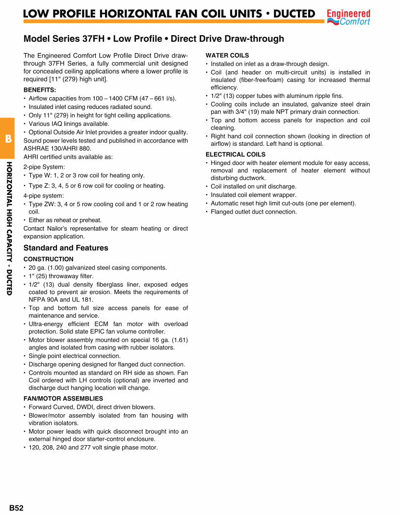
The Engineered Comfort Low Profile Direct Drive draw-through 37FH Series, a fully commercial unit designed for concealed ceiling applications where a lower profile is required [11" (279) high unit].
BENEFITS:• Airflow capacities from 100 – 1400 CFM (47 – 661 l/s).• Insulated inlet casing reduces radiated sound.• Only 11" (279) in height for tight ceiling applications.• Various IAQ linings available.• Optional Outside Air Inlet provides a greater indoor quality.Sound power levels tested and published in accordance with ASHRAE 130/AHRI 880.AHRI certified units available as:
2-pipe System: • Type W: 1, 2 or 3 row coil for heating only.
• Type Z: 3, 4, 5 or 6 row coil for cooling or heating.
4-pipe system: • Type ZW: 3, 4 or 5 row cooling coil and 1 or 2 row heating
coil.• Either as reheat or preheat.Contact Nailor’s representative for steam heating or direct expansion application.
Standard and Features CONSTRUCTION• 20 ga. (1.00) galvanized steel casing components.• 1" (25) throwaway filter. • 1/2" (13) dual density fiberglass liner, exposed edges
coated to prevent air erosion. Meets the requirements of NFPA 90A and UL 181.
• Top and bottom full size access panels for ease of maintenance and service.
• Ultra-energy efficient ECM fan motor with overload protection. Solid state EPIC fan volume controller.
• Motor blower assembly mounted on special 16 ga. (1.61) angles and isolated from casing with rubber isolators.
• Single point electrical connection.• Discharge opening designed for flanged duct connection.• Controls mounted as standard on RH side as shown. Fan
Coil ordered with LH controls (optional) are inverted and discharge duct hanging location will change.
FAN/MOTOR ASSEMBLIES• Forward Curved, DWDI, direct driven blowers. • Blower/motor assembly isolated from fan housing with
vibration isolators.• Motor power leads with quick disconnect brought into an
external hinged door starter-control enclosure. • 120, 208, 240 and 277 volt single phase motor.
WATER COILS• Installed on inlet as a draw-through design.• Coil (and header on multi-circuit units) is installed in
insulated (fiber-free/foam) casing for increased thermal efficiency.
• 1/2" (13) copper tubes with aluminum ripple fins.• Cooling coils include an insulated, galvanize steel drain
pan with 3/4" (19) male NPT primary drain connection. • Top and bottom access panels for inspection and coil
cleaning.• Right hand coil connection shown (looking in direction of
airflow) is standard. Left hand is optional.
ELECTRICAL COILS• Hinged door with heater element module for easy access,
removal and replacement of heater element without disturbing ductwork.
• Coil installed on unit discharge.• Insulated coil element wrapper.• Automatic reset high limit cut-outs (one per element).• Flanged outlet duct connection.
Model Series 37FH • Low Profile • Direct Drive Draw-through
HO
RIZ
ON
TAL H
IGH
CA
PACITY
- DU
CTED
B
LOW PROFILE HORIZONTAL FAN COIL UNITS • DUCTED
B52

Options and AccessoriesCONSTRUCTION
Insulation • 1/2" (13) Steri-Liner (Foil Face).• Fiber-free Liner (closed cell foam).• 1" (25) or 2" (51) Filter Rack• 1" (25) Throwaway filter with spare. • 2" (51) MERV 8 / MERV 13.• 2" (51) MERV 8 / MERV 13 with spare
COILS• Manual or Automatic air vent(s) with valve package. • Coil Casing 20 ga. (1.00) stainless steel drain pan externally
insulated with fiber-free foam.• Stainless steel coil casing.• Increased tube wall thickness 0.025" (0.635).
DRAIN PANS• Stainless Steel drain pan externally insulated with fiber-
free foam.• 5/8" (15.9) Secondary (overflow) drain connection with or
without overflow safety switch.
CONTROL PACKAGES• Toggle Disconnect Switch.• Door Interlocking disconnect switch.• Main Unit Fusing.• Drain Pan Float Switch (24V).• 24V transformer and fan relay packages.• Factory installed controls – provided by others.
VALVE-PIPING PACKAGES• Factory assembled and Installed in enclosure or field
installed.• 1/2" or 3/4" (13 or 19) 2 or 3 way valves. • On/Off, 24V, modulating 0–10 vdc.• Ball valves, Unions, P/T ports and Shut-off valves.• Circuit setters (manual or auto-fixed flow control).• Strainers and Strainer with hose bib valve.• P/T ports and Bypass balancing valve.
OTHER OPTIONS• Ultraviolet light w/safety switch.• Ducted return filter rack connection (FFR).• Outside Air Inlet (OAI).• Duct tight controls enclosure.• Condensate pump.
Model Series 37FH • Low Profile • Direct Drive Draw-through
37FHZW with EPIC ECM Motor, Optional Outside Air Inlet, Optional Controls Enclosure and Optional Ducted Filter Rack Connection
HO
RIZ
ON
TAL H
IGH
CA
PACITY
- DU
CTED
B
LOW PROFILE HORIZONTAL FAN COIL UNITS • DUCTED
B53
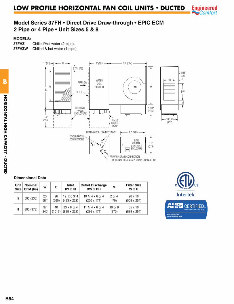
23" (584)1" (25) IH
2 7/8" (73)
WATERCOIL
SECTION
AIRFLOW
15" (381)
EWIW
PRIMARY DRAIN CONNECTIONOPTIONAL SECONDARY DRAIN CONNECTION
COOLING COILCONNECTIONS
HEATING COIL CONNECTIONS
11"(279)
5 3/4"(146)
10 1/8"(257)
LINEVOLTAGE
CONTROLSENCLOSURE
FILTER
14"(356)
OPTIONALVALVE
ENCLOSURE
VALVEACCESS
DOOR
FAN
DH
2 1/16"(52)
M
DW
12" (305)
MODELS:37FHZ Chilled/Hot water (2-pipe).37FHZW Chilled & hot water (4-pipe).
Unit Size
NominalCFM (l/s)
W EInlet
IW x IHOutlet Discharge
DW x DHM
Filter Size W x H
5 500 (236)23
(584)26
(660)19 x 8 3/ 4(483 x 222)
10 1/ 4 x 6 3/ 4(260 x 171)
2 3/ 4(70)
20 x 10(508 x 254)
8 800 (378)37
(940)40
(1016)33 x 8 3/ 4(838 x 222)
11 1/ 4 x 6 3/ 4 (286 x 171)
10 5/ 8(270)
35 x 10(889 x 254)
Dimensional Data
Model Series 37FH • Direct Drive Draw-through • EPIC ECM2 Pipe or 4 Pipe • Unit Sizes 5 & 8
HO
RIZ
ON
TAL H
IGH
CA
PACITY
- DU
CTED
B
LOW PROFILE HORIZONTAL FAN COIL UNITS • DUCTED
B54
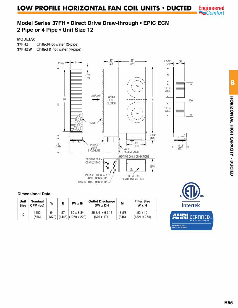
Model Series 37FH • Direct Drive Draw-through • EPIC ECM 2 Pipe or 4 Pipe • Unit Size 12
Dimensional Data
Unit Size
NominalCFM (l/s)
W E IW x IHOutlet Discharge
DW x DHM
Filter SizeW x H
121200 (566)
54 (1372)
57(1448)
50 x 8 3/4(1270 x 222)
26 3/4 x 6 3/ 4(679 x 171)
13 5/8(346)
52 x 10 (1321 x 254)
AIRFLOW
FILTER
15"(381)
11"(279)
LINE VOLTAGECONTROLS ENCLOSURE
IH23"
(584)12"
(305)
W
1" (25)
2 7/8"(73)
IW
EDW
10 1/8"(257)
2 1/16"(52)
11 1/4"(286)
11 1/4"(286)
M
5 3/4"(146)
DH
OPTIONAL SECONDARYDRAIN CONNECTION
PRIMARY DRAIN CONNECTION
OPTIONALVALVE
ENCLOSURE VALVEACCESS DOOR
14"(356)
FAN
FAN
COOLING COILCONNECTIONS
HEATING COIL CONNECTIONS
WATERCOIL
SECTION
MODELS:37FHZ Chilled/Hot water (2-pipe).37FHZW Chilled & hot water (4-pipe).
HO
RIZ
ON
TAL H
IGH
CA
PACITY
- DU
CTED
B
LOW PROFILE HORIZONTAL FAN COIL UNITS • DUCTED
B55
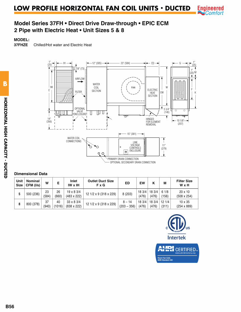
Model Series 37FH • Direct Drive Draw-through • EPIC ECM2 Pipe with Electric Heat • Unit Sizes 5 & 8
Dimensional Data
Unit Size
NominalCFM (l/s)
W EInlet
IW x IHOutlet Duct Size
F x GED EW K M
Filter SizeW x H
5 500 (236)23
(584)26
(660)19 x 8 3/4
(483 x 222)12 1/2 x 9 (318 x 229) 8 (203)
18 3/4 (476)
18 3/4 (476)
6 1/8 (156)
20 x 10 (508 x 254)
8 800 (378)37
(940)40
(1016)33 x 8 3/4
(838 x 222)12 1/2 x 9 (318 x 229)
8 – 14 (203 – 356)
18 3/4 (476)
18 3/4 (476)
12 1/4 (311)
10 x 35(254 x 889)
IH
2 7/8" (73)
WATERCOIL
SECTION
AIRFLOW
15" (381)
EIW
PRIMARY DRAIN CONNECTIONOPTIONAL SECONDARY DRAIN CONNECTION
WATER COILCONNECTIONS
11"(279)
10 1/8"(257)
LINEVOLTAGE
CONTROLSENCLOSURE
FILTER
14"(356)
OPTIONALVALVE
ENCLOSURE
FAN
HINGEDFOR ELEMENTREMOVAL
ELECTRICHEAT
SECTION
12" (305) 23" (584) ED G
1"(25) M
KF
EW
W
5 3/4"(146)
1"(25)
1"(25)
MODEL:37FHZE Chilled/Hot water and Electric Heat
HO
RIZ
ON
TAL H
IGH
CA
PACITY
- DU
CTED
B
LOW PROFILE HORIZONTAL FAN COIL UNITS • DUCTED
B56
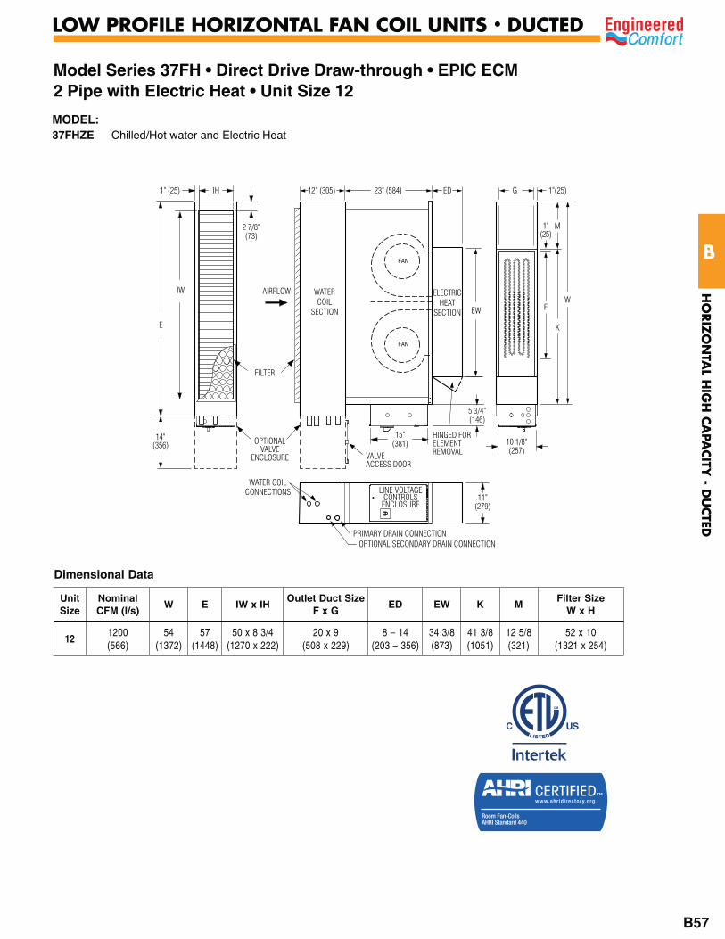
Model Series 37FH • Direct Drive Draw-through • EPIC ECM2 Pipe with Electric Heat • Unit Size 12
AIRFLOW
FILTER
15"(381)
11"(279)
LINE VOLTAGECONTROLSENCLOSURE
IH1" (25)
2 7/8"(73)
IW
E
10 1/8"(257)
OPTIONALVALVE
ENCLOSURE VALVEACCESS DOOR
14"(356)
FAN
FAN
WATER COILCONNECTIONS
PRIMARY DRAIN CONNECTIONOPTIONAL SECONDARY DRAIN CONNECTION
HINGED FORELEMENTREMOVAL
5 3/4"(146)
G 1"(25)
1"(25)
W
M
K
F
12" (305) 23" (584) ED
WATERCOIL
SECTION
ELECTRICHEAT
SECTION EW
Dimensional Data
Unit Size
NominalCFM (l/s)
W E IW x IHOutlet Duct Size
F x GED EW K M
Filter SizeW x H
121200 (566)
54 (1372)
57(1448)
50 x 8 3/4(1270 x 222)
20 x 9(508 x 229)
8 – 14 (203 – 356)
34 3/8 (873)
41 3/8(1051)
12 5/8(321)
52 x 10 (1321 x 254)
MODEL:37FHZE Chilled/Hot water and Electric Heat
HO
RIZ
ON
TAL H
IGH
CA
PACITY
- DU
CTED
B
LOW PROFILE HORIZONTAL FAN COIL UNITS • DUCTED
B57
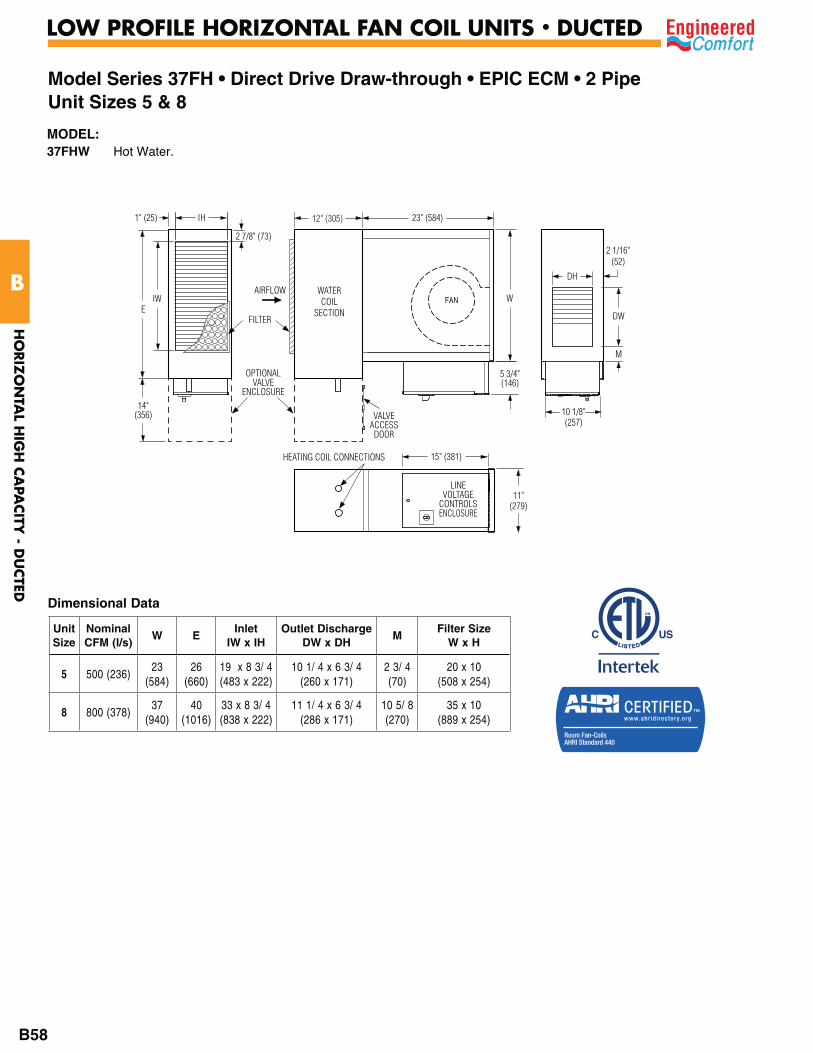
Model Series 37FH • Direct Drive Draw-through • EPIC ECM • 2 PipeUnit Sizes 5 & 8
23" (584)1" (25) IH
2 7/8" (73)
WATERCOIL
SECTION
AIRFLOW
15" (381)
EWIW
HEATING COIL CONNECTIONS
11"(279)
5 3/4"(146)
10 1/8"(257)
LINEVOLTAGE
CONTROLSENCLOSURE
FILTER
14"(356)
OPTIONALVALVE
ENCLOSURE
VALVEACCESS
DOOR
FAN
DH
2 1/16"(52)
M
DW
12" (305)
Dimensional Data
Unit Size
NominalCFM (l/s)
W EInlet
IW x IHOutlet Discharge
DW x DHM
Filter SizeW x H
5 500 (236)23
(584)26
(660)19 x 8 3/ 4(483 x 222)
10 1/ 4 x 6 3/ 4(260 x 171)
2 3/ 4(70)
20 x 10(508 x 254)
8 800 (378)37
(940)40
(1016)33 x 8 3/ 4(838 x 222)
11 1/ 4 x 6 3/ 4 (286 x 171)
10 5/ 8(270)
35 x 10(889 x 254)
MODEL:37FHW Hot Water.
HO
RIZ
ON
TAL H
IGH
CA
PACITY
- DU
CTED
B
LOW PROFILE HORIZONTAL FAN COIL UNITS • DUCTED
B58
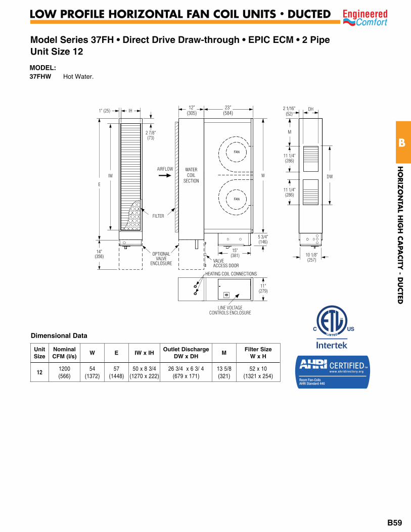
Model Series 37FH • Direct Drive Draw-through • EPIC ECM • 2 Pipe Unit Size 12
Dimensional Data
AIRFLOW
FILTER
15"(381)
11"(279)
LINE VOLTAGECONTROLS ENCLOSURE
IH23"
(584)12"
(305)
W
1" (25)
2 7/8"(73)
IW
E
DW
10 1/8"(257)
2 1/16"(52)
11 1/4"(286)
11 1/4"(286)
M
5 3/4"(146)
DH
OPTIONALVALVE
ENCLOSURE VALVEACCESS DOOR
14"(356)
FAN
FAN
HEATING COIL CONNECTIONS
WATERCOIL
SECTION
Unit Size
NominalCFM (l/s)
W E IW x IHOutlet Discharge
DW x DHM
Filter SizeW x H
121200 (566)
54 (1372)
57(1448)
50 x 8 3/4(1270 x 222)
26 3/4 x 6 3/ 4(679 x 171)
13 5/8(321)
52 x 10 (1321 x 254)
MODEL:37FHW Hot Water.
HO
RIZ
ON
TAL H
IGH
CA
PACITY
- DU
CTED
B
LOW PROFILE HORIZONTAL FAN COIL UNITS • DUCTED
B59

Model Series 37FH • Direct Drive Draw Through • EPIC ECMElectric Heat Only • Unit Sizes 5, 8 & 12
1" (25) IH
2 7/8" (73)
AIRFLOW
15" (381)
E IW
11"(279)
10 1/8"(257)
LINEVOLTAGE
CONTROLSENCLOSURE
FILTERFAN
HINGEDFOR ELEMENTREMOVAL
ELECTRICHEAT
SECTION
23" (584) ED
EW
G 1"(25)
1"(25)
W
M
KF
5 3/4"(146)
Dimensional Data
Unit Size
NominalCFM (l/s)
W EInlet
IW x IHOutlet Duct Size
F x GED EW K M
Filter SizeW x H
5 500 (236)23
(584)23
(584)17 1/4 x 8 3/4
(438 x 222)12 1/2 x 9 (318 x
229)8 (203)
18 3/4 (476)
18 3/4 (476)
6 1/8 (156)
20 x 10(508 x 254)
8 800 (378)37
(950)37
(940)31 1/4 x 8 3/4
(794 x 222)12 1/2 x 9 (318 x
229)8 – 14
(203 – 356)18 3/4 (476)
18 3/4 (476)
12 1/4 (311)
35 x 10(889 x 254)
MODEL:37FHE Electric Heat.
HO
RIZ
ON
TAL H
IGH
CA
PACITY
- DU
CTED
B
LOW PROFILE HORIZONTAL FAN COIL UNITS • DUCTED
B60

Model Series 37FH • Direct Drive Draw-through • EPIC ECMElectric Heat Only • Unit Sizes 5, 8 & 12
AIRFLOW
FILTER
15"(381)
11"(279)
LINE VOLTAGECONTROLSENCLOSURE
IH1" (25)
2 7/8"(73)
IWE
10 1/8"(257)
FAN
FAN
HINGED FORELEMENTREMOVAL
G 1"(25)
1"(25)
W
M
K
FEW
23" (584) ED
5 3/4"(146)
ELECTRICHEAT
SECTION
Dimensional Data
Unit Size
NominalCFM (l/s)
W E IW x IHOutlet Duct Size
F x GED EW K M
Filter SizeW x H
121200 (566)
54 (1372)
54(1370)
48 1/4 x 8 3/4(1226 x 222)
20 x 9(508 x 229)
8 – 14 (203 – 356)
34 3/8 (873)
41 3/8(1051)
12 5/8(321)
52 x 10 (1321 x 254)
MODEL:37FHE Electric Heat.
HO
RIZ
ON
TAL H
IGH
CA
PACITY
- DU
CTED
B
LOW PROFILE HORIZONTAL FAN COIL UNITS • DUCTED
B61
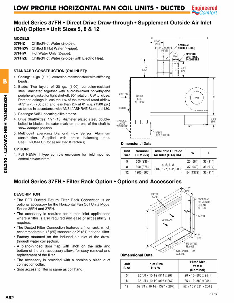
Model Series 37FH • Direct Drive Draw-through • Supplement Outside Air Inlet (OAI) Option • Unit Sizes 5, 8 & 12
WATERCOIL
SECTION
AIRFLOWW
5 3/4"(146)
FILTER
VALVEACCESS DOOR
FAN
OPTIONALVALVE
ENCLOSURE
11 1/2"(292)
CL
L
OPTIONALAIR INLET (OAI)
OPTIONALCONTROLSENCLOSURE
9 3/4"(248)
5"(127)
8 1/4"(210)
DIA. = NOM.- 1/8" (3)
MODELS:37FHZ Chilled/Hot Water (2-pipe).37FHZW Chilled & Hot Water (4-pipe).37FHW Hot Water Only (2-pipe).37FHZE Chilled/Hot Water (2-pipe) with Electric Heat.
Dimensional Data
Unit Size
NominalCFM (l/s)
Available Outside Air Inlet (OAI) DIA.
W L
5 500 (236)4, 5, 6, 8
(102, 127, 152, 203)
23 (584) 36 (914)
8 800 (378) 37 (940) 36 (914)
12 1200 (566) 54 (1372) 36 (914)
STANDARD CONSTRUCTION (OAI INLET):
1. Casing: 20 ga. (1.00), corrosion-resistant steel with stiffening beads.
2. Blade: Two layers of 20 ga. (1.00), corrosion-resistant steel laminated together with a cross-linked polyethylene peripheral gasket for tight shut-off. 90° rotation, CW to close. Damper leakage is less the 1% of the terminal rated airflow at 3" w.g. (750 pa.) and less than 2% at 6" w.g. (1500 pa.) as tested in accordance with ANSI / ASHRAE Standard 130.
3. Bearings: Self-lubricating oilite bronze.
4. Drive Shaft/Axles: 1/2" (13) diameter plated steel, double-bolted to blades. Indicator mark on the end of the shaft to show damper position.
5. Multi-point averaging Diamond Flow Sensor: Aluminum construction. Supplied with brass balancing tees. See EC-IOM-FCK for associated K-factor(s).
OPTION:1. Full NEMA 1 type controls enclosure for field mounted
controllers/actuators.
DESCRIPTION• The FFR Ducted Return Filter Rack Connection is an
optional accessory for the Horizontal Fan Coil Units Model Series 35FH and 37FH.
• The accessory is required for ducted inlet applications where a filter is also required and ease of accessibility is required.
• The Ducted Filter Connection features a filter rack, which accommodates a 1" (25) standard or 2" (51) optional filter.
• Factory mounted on the induced air inlet of the draw-through water coil section.
• A piano-hinged door flap with latch on the side and bottom of the unit accessory allows for easy removal and replacement of the filter.
• The accessory is provided with a nominally sized duct connection collar.
• Side access to filter is same as coil hand.
Dimensional Data
Unit Size
Inlet Size H x W
Filter SizeW x H
(Nominal)
5 20 x 10 (508 x 254)
8 35 x 10 (889 x 254)
12 52 x 10 (1321 x 254 )
1"(25)
H
DOOR FLAPOPENING ONSIDE ANDBOTTOM
SIDE AND BOTTOMACCESS
LATCH
FILTERRACK
MOUNTINGFLANGE
AIRFLOW
5 1/2"(140)
W
Model Series 37FH • Filter Rack Option • Options and Accessories
7-8-19
HO
RIZ
ON
TAL H
IGH
CA
PACITY
- DU
CTED
B
LOW PROFILE HORIZONTAL FAN COIL UNITS • DUCTED
B62
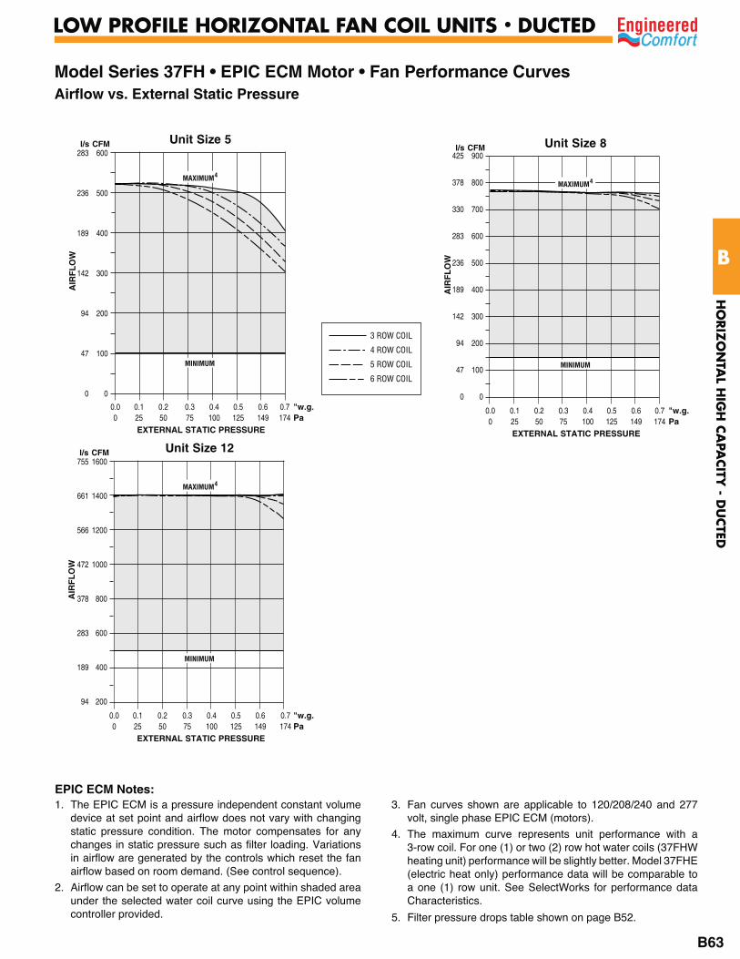
Model Series 37FH • EPIC ECM Motor • Fan Performance CurvesAirflow vs. External Static Pressure
Unit Size 8900
800
700
600
500
400
300
200
100
0
AIR
FL
OW
l/s CFM425
378
330
283
236
189
142
94
47
0
0.0 0.1 0.2 0.3 0.4 0.5 0.6 0.7 "w.g. 0 25 50 75 100 125 149 174 Pa EXTERNAL STATIC PRESSURE
Unit Size 121600
1400
1200
1000
800
600
400
200
AIR
FL
OW
l/s CFM755
661
566
472
378
283
189
94
Unit Size 5600
500
400
300
200
100
0
AIR
FL
OW
l/s CFM283
236
189
142
94
47
0
0.0 0.1 0.2 0.3 0.4 0.5 0.6 0.7 "w.g. 0 25 50 75 100 125 149 174 Pa EXTERNAL STATIC PRESSURE
MINIMUM MINIMUM
MINIMUM
3 ROW COIL
4 ROW COIL
5 ROW COIL
6 ROW COIL
EPIC ECM Notes:
MAXIMUM4
MAXIMUM4
MAXIMUM4
0.0 0.1 0.2 0.3 0.4 0.5 0.6 0.7 "w.g. 0 25 50 75 100 125 149 174 Pa EXTERNAL STATIC PRESSURE
1. The EPIC ECM is a pressure independent constant volume device at set point and airflow does not vary with changing static pressure condition. The motor compensates for any changes in static pressure such as filter loading. Variations in airflow are generated by the controls which reset the fan airflow based on room demand. (See control sequence).
2. Airflow can be set to operate at any point within shaded area under the selected water coil curve using the EPIC volume controller provided.
3. Fan curves shown are applicable to 120/208/240 and 277 volt, single phase EPIC ECM (motors).
4. The maximum curve represents unit performance with a 3-row coil. For one (1) or two (2) row hot water coils (37FHW heating unit) performance will be slightly better. Model 37FHE (electric heat only) performance data will be comparable to a one (1) row unit. See SelectWorks for performance data Characteristics.
5. Filter pressure drops table shown on page B52.
HO
RIZ
ON
TAL H
IGH
CA
PACITY
- DU
CTED
B
LOW PROFILE HORIZONTAL FAN COIL UNITS • DUCTED
B63

Unit Size
VoltageNo. ofFans/
Motors
EPIC ECM
FLAFull Load
Watts
5
120 1/1 1.9
146208 1/1 1.3
230 1/1 1.2
277 1/1 1.2
8
120 1/1 3.8
320208 1/1 2.6
230 1/1 2.5
277 1/1 2.6
12
120 2/2 6.2
520208 2/2 4.1
230 2/2 3.9
277 2/2 3.8
Model Series 37FH • Performance DataElectrical Motor Characteristics
The FLA and watts are shown at the maximum setting for selected motor type and unit size. The EPIC ECM will provide a much lower amp and watt consumption under application conditions. Refer to SelectWorks selection software for application specific data.
Filter Pressure Drop Adjustments (in w.g.)
Unit Size
Airflow Velocity Filter TypeFilter Size
W x HCFM l/s fpm m/s1" (25)
Throwaway2" (51)
MERV 82" (51)
MERV 13
5
500 236 360 1.829 0.095 0.192 0.29620 x 10
(508 x 254)400 189 288 1.463 0.066 0.134 0.224
300 142 216 1.097 0.037 0.077 0.153
8
750 354 309 1.570 0.074 0.151 0.24535 x 10
(889 x 254)600 283 247 1.255 0.049 0.102 0.184
450 212 185 0.940 0.025 0.052 0.122
12
1400 661 388 1.971 0.106 0.214 0.32552 x 10
(1321 x 254)1120 529 310 1.575 0.075 0.152 0.247
840 396 233 1.184 0.044 0.090 0.169
Front: 1" (25) ThrowawayMiddle: 2" (51) MERV 13Back: 2" (51) MERV 8
NOTES:1. Pressure drop based on clean filters. Using any type of filter will lower unit airflow.
2. To determine fan airflow with the addition of a filter, add the filter pressure drop to the external static pressure on the fan curve or use Selectworks.
HO
RIZ
ON
TAL H
IGH
CA
PACITY
- DU
CTED
B
LOW PROFILE HORIZONTAL FAN COIL UNITS • DUCTED
B64
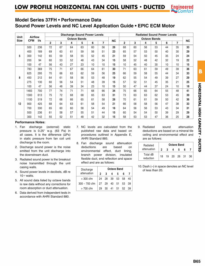
Model Series 37FH • Performance DataSound Power Levels and NC Level Application Guide • EPIC ECM Motor
Unit Size
AirflowCFM l/s
Discharge Sound Power Levels Radiated Sound Power Levels Octave Bands
NCOctave Bands
NC2 3 4 5 6 7 2 3 4 5 6 7
5
500 236 72 67 64 63 60 56 26 68 60 56 53 44 35 33400 189 69 63 61 59 56 51 23 65 57 53 50 40 30 29300 142 65 59 58 55 52 45 21 59 54 50 45 35 24 24200 94 60 53 52 48 43 34 15 58 52 48 42 32 19 22100 47 56 43 27 23 10 10 15 10 45 40 30 10 10 15
8
783 369 75 71 67 66 64 61 30 71 63 61 59 49 39 36625 295 70 66 63 62 59 56 25 66 59 58 55 44 34 33450 212 64 61 58 56 53 48 19 62 55 54 49 39 27 29275 130 60 56 54 51 48 39 15 57 52 51 45 35 21 25100 47 56 48 39 34 23 10 15 50 47 44 37 24 10 18
12
1483 700 77 74 71 71 68 66 34 75 66 65 64 55 48 411300 613 75 72 68 68 65 63 31 73 63 63 62 53 45 391100 519 72 68 66 65 61 58 26 70 61 61 59 50 42 36900 425 68 64 63 61 58 54 21 66 58 58 56 47 38 33700 330 65 60 60 58 54 49 16 64 56 56 53 43 34 31500 236 61 58 57 55 51 44 15 60 54 54 50 39 29 29300 142 55 52 51 48 42 32 15 58 53 53 47 36 25 28
Performance Notes:1. Fan discharge (external) static
pressure is 0.25" w.g. (63 Pa) in
in static pressure from fan coil unit discharge to the room.
2. Discharge sound power is the noise emitted from the unit discharge into the downstream duct.
3. Radiated sound power is the breakout noise transmitted through the unit casing walls.
4. Sound power levels in decibels, dB re 10-12 watts.
5. All sound data listed by octave bands is raw data without any corrections for room absorption or duct attenuation.
6. Data derived from independent tests in accordance with AHRI Standard 880.
7. NC levels are calculated from the published raw data and based on procedures outlined in Appendix E, AHRI Standard 885.
8. Fan discharge sound attenuation deductions are based on environmental effect, duct lining, branch power division, insulated flexible duct, end reflection and space effect and are as follows:
9. Radiated sound attenuation deductions are based on a mineral tile ceiling and environmental effect and are as follows:
10. Dash (–) in space denotes an NC level of less than 20.Discharge
attenuation Octave Band
2 3 4 5 6 7
< 300 cfm 24 28 39 53 58 40
300 – 700 cfm 27 29 40 51 53 39
> 700 cfm 29 30 41 51 52 39
Radiated attenuation
Octave Band
2 3 4 5 6 7
Total dB reduction
18 19 20 26 31 36
HO
RIZ
ON
TAL H
IGH
CA
PACITY
- DU
CTED
B
LOW PROFILE HORIZONTAL FAN COIL UNITS • DUCTED
B65
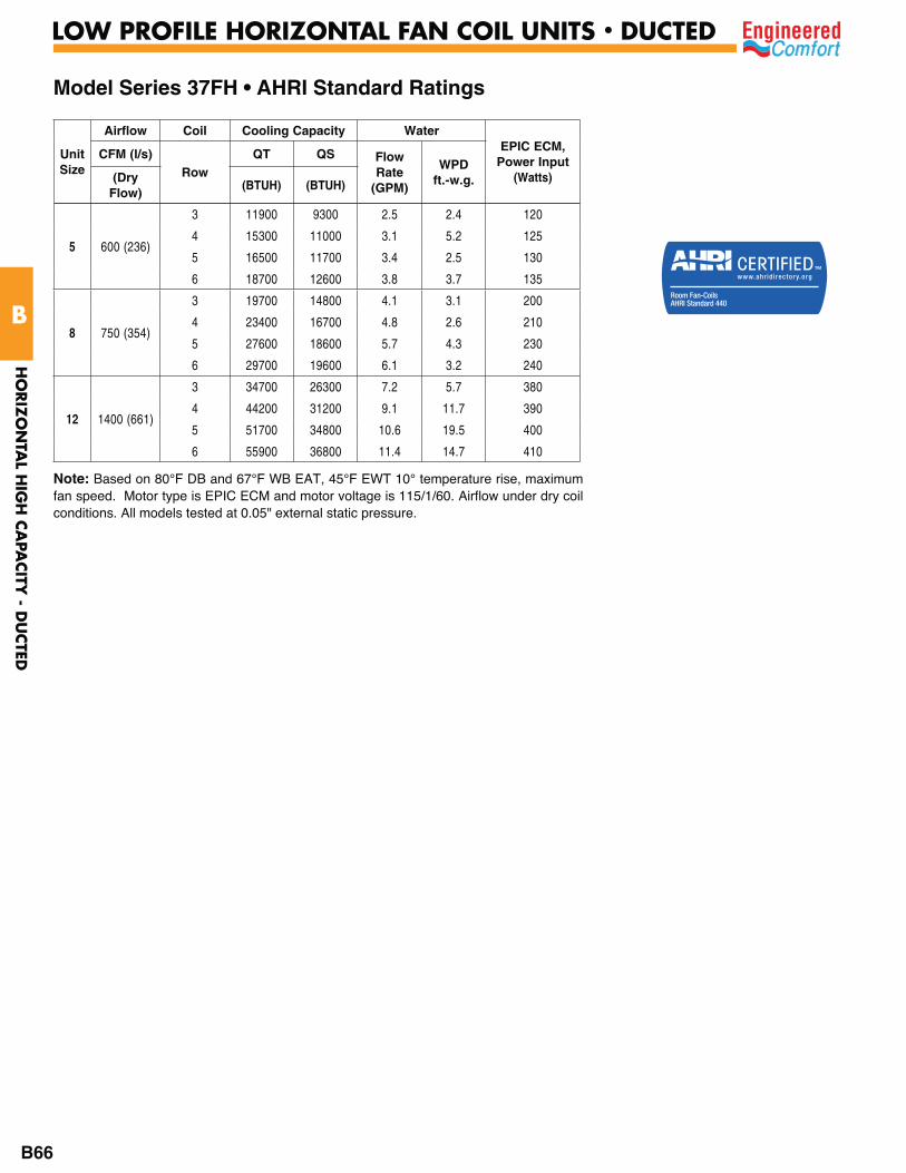
Note: Based on 80°F DB and 67°F WB EAT, 45°F EWT 10° temperature rise, maximum fan speed. Motor type is EPIC ECM and motor voltage is 115/1/60. Airflow under dry coil conditions. All models tested at 0.05" external static pressure.
Model Series 37FH • AHRI Standard Ratings
Unit Size
Airflow Coil Cooling Capacity WaterEPIC ECM,
Power Input(Watts)
CFM (l/s)Row
QT QS Flow Rate
(GPM)
WPDft.-w.g.(Dry
Flow)(BTUH) (BTUH)
5 600 (236)
3 11900 9300 2.5 2.4 120
4 15300 11000 3.1 5.2 125
5 16500 11700 3.4 2.5 130
6 18700 12600 3.8 3.7 135
8 750 (354)
3 19700 14800 4.1 3.1 200
4 23400 16700 4.8 2.6 210
5 27600 18600 5.7 4.3 230
6 29700 19600 6.1 3.2 240
12 1400 (661)
3 34700 26300 7.2 5.7 380
4 44200 31200 9.1 11.7 390
5 51700 34800 10.6 19.5 400
6 55900 36800 11.4 14.7 410
HO
RIZ
ON
TAL H
IGH
CA
PACITY
- DU
CTED
B
LOW PROFILE HORIZONTAL FAN COIL UNITS • DUCTED
B66
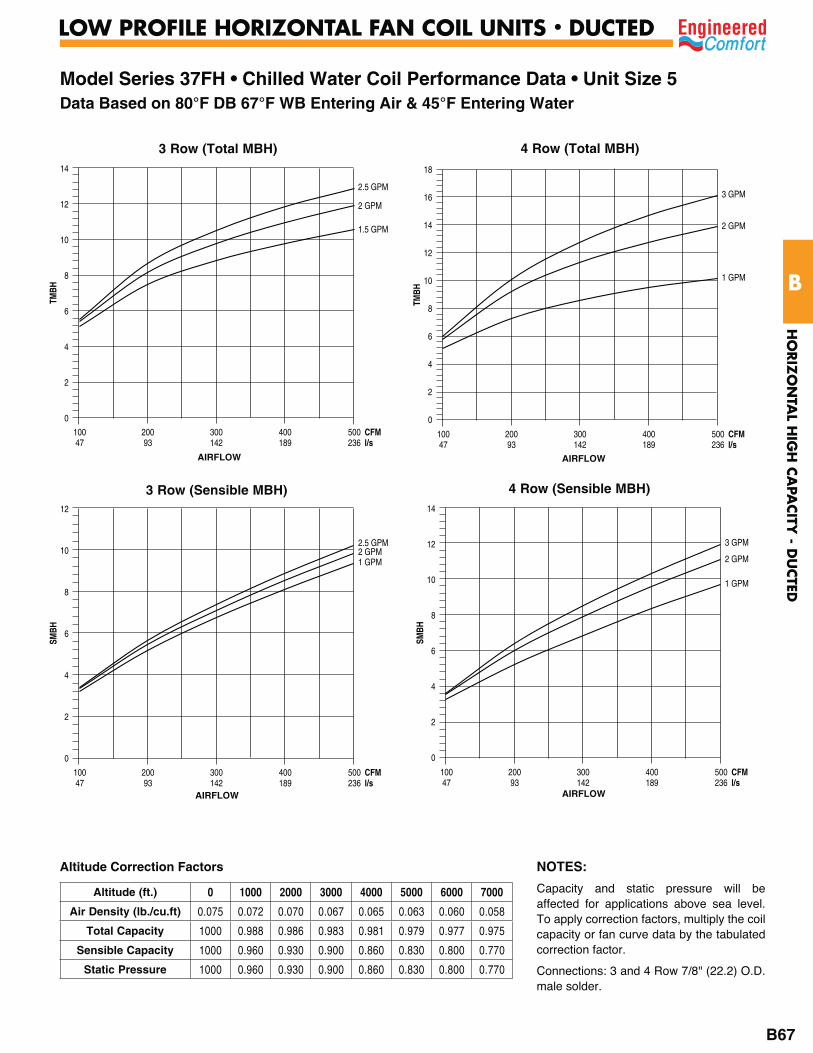
Model Series 37FH • Chilled Water Coil Performance Data • Unit Size 5Data Based on 80°F DB 67°F WB Entering Air & 45°F Entering Water
3 Row (Total MBH)
TMBH
2 GPM
2.5 GPM
1.5 GPM
14
12
10
8
6
4
2
0
100 200 300 400 500 CFM 47 93 142 189 236 l/s
AIRFLOW
4 Row (Total MBH)
TMBH
2 GPM
3 GPM
1 GPM
18
16
14
12
10
8
6
4
2
0
100 200 300 400 500 CFM 47 93 142 189 236 l/s
AIRFLOW
3 Row (Sensible MBH)
SMBH
2 GPM2.5 GPM
1 GPM
12
10
8
6
4
2
0
100 200 300 400 500 CFM 47 93 142 189 236 l/s
4 Row (Sensible MBH)
SMBH
2 GPM
3 GPM
1 GPM
14
12
10
8
6
4
2
0
100 200 300 400 500 CFM 47 93 142 189 236 l/s
AIRFLOW
NOTES:
Capacity and static pressure will be affected for applications above sea level. To apply correction factors, multiply the coil capacity or fan curve data by the tabulated correction factor.
Connections: 3 and 4 Row 7/8" (22.2) O.D. male solder.
Altitude Correction Factors
Altitude (ft.) 0 1000 2000 3000 4000 5000 6000 7000
Air Density (lb./cu.ft) 0.075 0.072 0.070 0.067 0.065 0.063 0.060 0.058
Total Capacity 1000 0.988 0.986 0.983 0.981 0.979 0.977 0.975
Sensible Capacity 1000 0.960 0.930 0.900 0.860 0.830 0.800 0.770
Static Pressure 1000 0.960 0.930 0.900 0.860 0.830 0.800 0.770
AIRFLOW
HO
RIZ
ON
TAL H
IGH
CA
PACITY
- DU
CTED
B
LOW PROFILE HORIZONTAL FAN COIL UNITS • DUCTED
B67

Model Series 37FH • Chilled Water Coil Performance Data • Unit Size 5Data Based on 80°F DB 67°F WB Entering Air & 45°F Entering Water
5 Row (Total MBH)
TMBH
2 GPM
3.5 GPM
1 GPM
20
18
16
14
12
10
8
6
4
2
0
100 200 300 400 500 CFM 47 93 142 189 236 l/s
AIRFLOW
5 Row (Sensible MBH)
SMBH
2 GPM
3.5 GPM
1 GPM
14
12
10
8
6
4
2
0
100 200 300 400 500 CFM 47 93 142 189 236 l/s
AIRFLOW
6 Row (Total MBH)
TMBH
3 GPM
4 GPM
1 GPM
25
20
15
10
5
0
100 200 300 400 500 CFM 47 93 142 189 236 l/s
AIRFLOW
6 Row (Sensible MBH)
SMBH
3 GPM4 GPM
1 GPM
16
14
12
10
8
6
4
2
0 100 200 300 400 500 CFM 47 93 142 189 236 l/s
AIRFLOW
NOTES:1. Capacity and static pressure will be
affected for applications above sea level. To apply correction factors, multiply the coil capacity or fan curve data by the tabulated correction factor.
2. Connections: 3 and 4 Row 7/8" (22.2) O.D. male solder.
Altitude Correction Factors
Altitude (ft.) 0 1000 2000 3000 4000 5000 6000 7000
Air Density (lb./cu. ft) 0.075 0.072 0.070 0.067 0.065 0.063 0.060 0.058
Total Capacity 1000 0.988 0.986 0.983 0.981 0.979 0.977 0.975
Sensible Capacity 1000 0.960 0.930 0.900 0.860 0.830 0.800 0.770
Static Pressure 1000 0.960 0.930 0.900 0.860 0.830 0.800 0.770
HO
RIZ
ON
TAL H
IGH
CA
PACITY
- DU
CTED
B
LOW PROFILE HORIZONTAL FAN COIL UNITS • DUCTED
B68

Model Series 37FH • Chilled Water Coil Performance Data • Unit Size 8Data Based on 80°F DB 67°F WB Entering Air & 45°F Entering Water
3 Row (Total MBH)
TMBH
3 GPM
4.5 GPM
2 GPM
25
20
15
10
5
0
200 300 400 500 600 700 800 CFM 93 142 189 236 283 330 378 l/s
AIRFLOW
4 Row (Total MBH)
TMBH
3 GPM
5 GPM
1.5 GPM
30
25
20
15
10
5
0
200 300 400 500 600 700 800 CFM 93 142 189 236 283 330 378 l/s
AIRFLOW
3 Row (Sensible MBH)
SMBH
3 GPM
4.5 GPM
2 GPM
18
16
14
12
10
8
6
4
2
0
200 300 400 500 600 700 800 CFM 93 142 189 236 283 330 378 l/s
4 Row (Sensible MBH)
SMBH
3 GPM
5GPM
1.5 GPM
25
20
15
10
5
0
200 300 400 500 600 700 800 CFM 93 142 189 236 283 330 378 l/s
AIRFLOW AIRFLOW
NOTES:1. Capacity and static pressure will be
affected for applications above sea level. To apply correction factors, multiply the coil capacity or fan curve data by the tabulated correction factor.
2. Connections: 3 and 4 Row 7/8" (22.2) O.D. male solder.
Altitude Correction Factors
Altitude (ft.) 0 1000 2000 3000 4000 5000 6000 7000
Air Density (lb./cu. ft) 0.075 0.072 0.070 0.067 0.065 0.063 0.060 0.058
Total Capacity 1000 0.988 0.986 0.983 0.981 0.979 0.977 0.975
Sensible Capacity 1000 0.960 0.930 0.900 0.860 0.830 0.800 0.770
Static Pressure 1000 0.960 0.930 0.900 0.860 0.830 0.800 0.770
HO
RIZ
ON
TAL H
IGH
CA
PACITY
- DU
CTED
B
LOW PROFILE HORIZONTAL FAN COIL UNITS • DUCTED
B69

Model Series 37FH • Chilled Water Coil Performance Data • Unit Size 8Data Based on 80°F DB 67°F WB Entering Air & 45°F Entering Water
5 Row (Total MBH)
TMBH
4 GPM
6 GPM
1.5 GPM
35
30
25
20
15
10
5
0 200 300 400 500 600 700 800 CFM 93 142 189 236 283 330 378 l/s
AIRFLOW
5 Row (Sensible MBH)
SMBH
4 GPM
6 GPM
1.5 GPM
25
20
15
10
5
0
200 300 400 500 600 700 800 CFM 93 142 189 236 283 330 378 l/s
AIRFLOW
6 Row (Total MBH)
TMBH
4 GPM
6.5 GPM
1.5 GPM
40
35
30
25
20
15
10
5
0
200 300 400 500 600 700 800 CFM 93 142 189 236 283 330 378 l/s
AIRFLOW
6 Row (Sensible MBH)
SMBH
4 GPM
6.5 GPM
1.5 GPM
25
20
15
10
5
0
200 300 400 500 600 700 800 CFM 93 142 189 236 283 330 378 l/s
AIRFLOW
NOTES:1. Capacity and static pressure will be
affected for applications above sea level. To apply correction factors, multiply the coil capacity or fan curve data by the tabulated correction factor.
2. Connections: 5 and 6 Row 7/8" (22.2) O.D. male solder.
Altitude Correction Factors
Altitude (ft.) 0 1000 2000 3000 4000 5000 6000 7000
Air Density (lb./cu. ft) 0.075 0.072 0.070 0.067 0.065 0.063 0.060 0.058
Total Capacity 1000 0.988 0.986 0.983 0.981 0.979 0.977 0.975
Sensible Capacity 1000 0.960 0.930 0.900 0.860 0.830 0.800 0.770
Static Pressure 1000 0.960 0.930 0.900 0.860 0.830 0.800 0.770
HO
RIZ
ON
TAL H
IGH
CA
PACITY
- DU
CTED
B
LOW PROFILE HORIZONTAL FAN COIL UNITS • DUCTED
B70

Model Series 37FH • Chilled Water Coil Performance Data • Unit Size 12Data Based on 80°F DB 67°F WB Entering Air & 45°F Entering Water
3 Row (Total MBH)
TMBH
5 GPM
7.5 GPM
3 GPM
40
35
30
25
20
15
10
5
0
400 600 800 1000 1200 1400 CFM 189 283 378 472 566 661 l/s
AIRFLOW
4 Row (Total MBH)
TMBH
6 GPM
4 GPM
9.5 GPM
3 GPM
60
50
40
30
20
10
0
400 600 800 1000 1200 1400 CFM 189 283 378 472 566 661 l/s
AIRFLOW
3 Row (Sensible MBH) 4 Row (Sensible MBH)
AIRFLOW AIRFLOW
NOTES:1. Capacity and static pressure will be
affected for applications above sea level. To apply correction factors, multiply the coil capacity or fan curve data by the tabulated correction factor.
2. Connections: 3 and 4 Row 7/8" (22.2) O.D. male solder.
Altitude Correction Factors
Altitude (ft.) 0 1000 2000 3000 4000 5000 6000 7000
Air Density (lb./cu. ft) 0.075 0.072 0.070 0.067 0.065 0.063 0.060 0.058
Total Capacity 1000 0.988 0.986 0.983 0.981 0.979 0.977 0.975
Sensible Capacity 1000 0.960 0.930 0.900 0.860 0.830 0.800 0.770
Static Pressure 1000 0.960 0.930 0.900 0.860 0.830 0.800 0.770
HO
RIZ
ON
TAL H
IGH
CA
PACITY
- DU
CTED
B
LOW PROFILE HORIZONTAL FAN COIL UNITS • DUCTED
B71
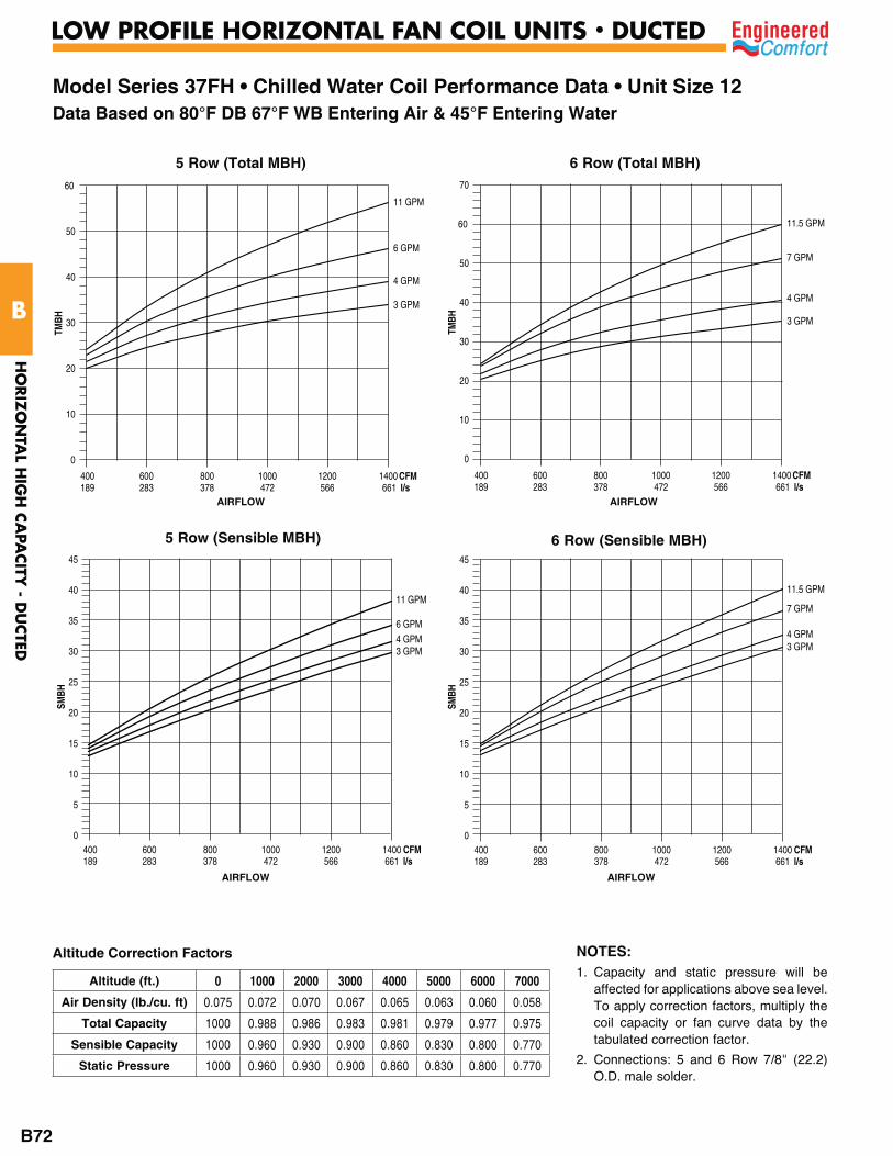
Model Series 37FH • Chilled Water Coil Performance Data • Unit Size 12Data Based on 80°F DB 67°F WB Entering Air & 45°F Entering Water
5 Row (Total MBH)
TMBH
6 GPM
4 GPM
11 GPM
3 GPM
60
50
40
30
20
10
0
400 600 800 1000 1200 1400 CFM 189 283 378 472 566 661 l/s
AIRFLOW
5 Row (Sensible MBH)
AIRFLOW
6 Row (Total MBH)
TMBH
7 GPM
4 GPM
11.5 GPM
3 GPM
70
60
50
40
30
20
10
0
400 600 800 1000 1200 1400 CFM 189 283 378 472 566 661 l/s
AIRFLOW
6 Row (Sensible MBH)
AIRFLOW
NOTES:1. Capacity and static pressure will be
affected for applications above sea level. To apply correction factors, multiply the coil capacity or fan curve data by the tabulated correction factor.
2. Connections: 5 and 6 Row 7/8" (22.2) O.D. male solder.
Altitude Correction Factors
Altitude (ft.) 0 1000 2000 3000 4000 5000 6000 7000
Air Density (lb./cu. ft) 0.075 0.072 0.070 0.067 0.065 0.063 0.060 0.058
Total Capacity 1000 0.988 0.986 0.983 0.981 0.979 0.977 0.975
Sensible Capacity 1000 0.960 0.930 0.900 0.860 0.830 0.800 0.770
Static Pressure 1000 0.960 0.930 0.900 0.860 0.830 0.800 0.770
HO
RIZ
ON
TAL H
IGH
CA
PACITY
- DU
CTED
B
LOW PROFILE HORIZONTAL FAN COIL UNITS • DUCTED
B72
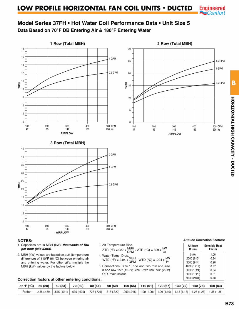
Model Series 37FH • Hot Water Coil Performance Data • Unit Size 5Data Based on 70°F DB Entering Air & 180°F Entering Water
2 Row (Total MBH)
TMBH
1 GPM
0.5 GPM
18
16
14
12
10
8
6
4
2
0
100 200 300 400 500 CFM 47 93 142 189 236 l/s
1 Row (Total MBH)
3 Row (Total MBH)
TMBH
1.5 GPM
1 GPM
0.5 GPM
30
25
20
15
10
5
0
100 200 300 400 500 CFM 47 93 142 189 236 l/s
TMBH
1 GPM
2 GPM
0.5 GPM
45
40
35
30
25
20
15
10
5
0
100 200 300 400 500 CFM 47 93 142 189 236 l/s
AIRFLOW AIRFLOW
AIRFLOW
Correction factors at other entering conditions:
1. Capacities are in MBH (kW), thousands of Btu per hour (kiloWatts).
2. MBH (kW) values are based on a t (temperature difference) of 110°F (61°C) between entering air and entering water. For other t's; multiply the MBH (kW) values by the factors below.
3. Air Temperature Rise.
4. Water Temp. Drop.
5. Connections: Size 1, one and two row and size 3 one row 1/2" (12.7); Size 3 two row 7/8" (22.2) O.D. male solder.
ATR (°C) = 829 x kW l/s
ATR (°F) = 927 x MBH , CFM
WTD (°C) = .224 x kW l/s
WTD (°F) = 2.04 x MBH , GPM
NOTES:
50 (28) 60 (33) 70 (39) 80 (44) 90 (50) 100 (56) 110 (61) 120 (67) 130 (72) 140 (78) 150 (83)
Factor .455 (.459) .545 (.541) .636 (.639) .727 (.721) .818 (.820) .909 (.918) 1.00 (1.00) 1.09 (1.10) 1.18 (1.18) 1.27 (1.28) 1.36 (1.36)
Altitude Correction Factors:
Altitude ft. (m)
Sensible Heat Factor
0 (0)2000 (610) 3000 (914)
4000 (1219) 5000 (1524) 6000 (1829) 7000 (2134)
1.00 0.94 0.90 0.87 0.84 0.81 0.78
HO
RIZ
ON
TAL H
IGH
CA
PACITY
- DU
CTED
B
LOW PROFILE HORIZONTAL FAN COIL UNITS • DUCTED
B73
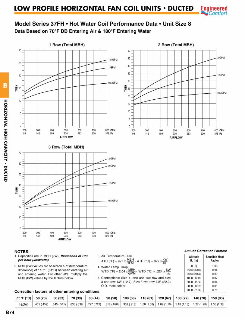
Model Series 37FH • Hot Water Coil Performance Data • Unit Size 8Data Based on 70°F DB Entering Air & 180°F Entering Water
2 Row (Total MBH)
TMBH
1.5 GPM
1 GPM
0.5 GPM
30
25
20
15
10
5
0
200 300 400 500 600 700 800 CFM 93 142 189 236 283 330 378 l/s
1 Row (Total MBH)
3 Row (Total MBH)
TMBH
1 GPM
2 GPM
0.5 GPM
50
45
40
35
30
25
20
19
10
5
0
200 300 400 500 600 700 800 CFM 93 142 189 236 283 330 378 l/s
TMBH
2 GPM
3 GPM
1 GPM
0.5 GPM
70
60
50
40
30
20
10
0
200 300 400 500 600 700 800 CFM 93 142 189 236 283 330 378 l/s
AIRFLOW AIRFLOW
AIRFLOW
Correction factors at other entering conditions:
1. Capacities are in MBH (kW), thousands of Btu per hour (kiloWatts).
2. MBH (kW) values are based on a t (temperature difference) of 110°F (61°C) between entering air and entering water. For other t's; multiply the MBH (kW) values by the factors below.
3. Air Temperature Rise.
4. Water Temp. Drop.
5. Connections: Size 1, one and two row and size 3 one row 1/2" (12.7); Size 3 two row 7/8" (22.2) O.D. male solder.
ATR (°C) = 829 x kW l/s
ATR (°F) = 927 x MBH , CFM
WTD (°C) = .224 x kW l/s
WTD (°F) = 2.04 x MBH , GPM
NOTES:
50 (28) 60 (33) 70 (39) 80 (44) 90 (50) 100 (56) 110 (61) 120 (67) 130 (72) 140 (78) 150 (83)
Factor .455 (.459) .545 (.541) .636 (.639) .727 (.721) .818 (.820) .909 (.918) 1.00 (1.00) 1.09 (1.10) 1.18 (1.18) 1.27 (1.28) 1.36 (1.36)
Altitude Correction Factors:
Altitude ft. (m)
Sensible Heat Factor
0 (0)2000 (610) 3000 (914)
4000 (1219) 5000 (1524) 6000 (1829) 7000 (2134)
1.00 0.94 0.90 0.87 0.84 0.81 0.78
HO
RIZ
ON
TAL H
IGH
CA
PACITY
- DU
CTED
B
LOW PROFILE HORIZONTAL FAN COIL UNITS • DUCTED
B74
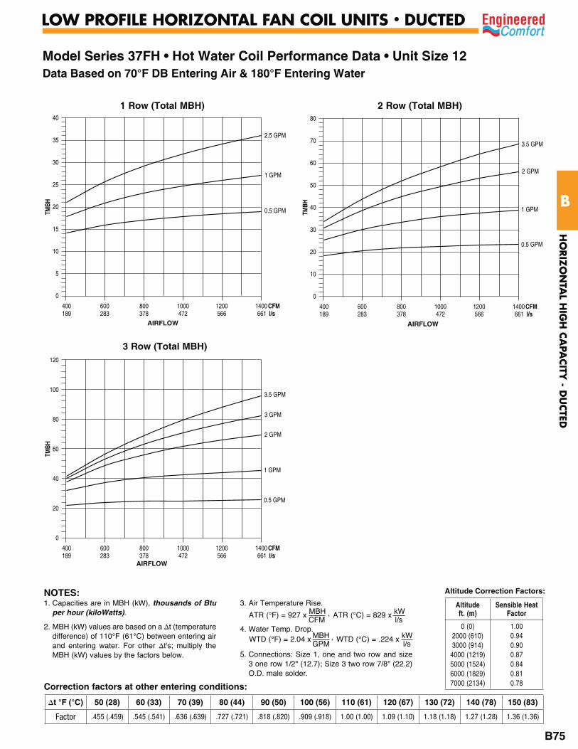
Model Series 37FH • Hot Water Coil Performance Data • Unit Size 12Data Based on 70°F DB Entering Air & 180°F Entering Water
2 Row (Total MBH)
TMBH
2.5 GPM
1 GPM
0.5 GPM
40
35
30
25
20
15
10
5
0
400 600 800 1000 1200 1400 CFM 189 283 378 472 566 661 l/s
1 Row (Total MBH)
3 Row (Total MBH)
TMBH
3.5 GPM
2 GPM
0.5 GPM
1 GPM
80
70
60
50
40
30
20
10
0
400 600 800 1000 1200 1400 CFM 189 283 378 472 566 661 l/s
TMBH
3.5 GPM
2 GPM
3 GPM
0.5 GPM
1 GPM
120
100
80
60
40
20
0
400 600 800 1000 1200 1400 CFM 189 283 378 472 566 661 l/s
AIRFLOW AIRFLOW
AIRFLOW
Correction factors at other entering conditions:
1. Capacities are in MBH (kW), thousands of Btu per hour (kiloWatts).
2. MBH (kW) values are based on a t (temperature difference) of 110°F (61°C) between entering air and entering water. For other t's; multiply the MBH (kW) values by the factors below.
3. Air Temperature Rise.
4. Water Temp. Drop.
5. Connections: Size 1, one and two row and size 3 one row 1/2" (12.7); Size 3 two row 7/8" (22.2) O.D. male solder.
ATR (°C) = 829 x kW l/s
ATR (°F) = 927 x MBH , CFM
WTD (°C) = .224 x kW l/s
WTD (°F) = 2.04 x MBH , GPM
NOTES:
50 (28) 60 (33) 70 (39) 80 (44) 90 (50) 100 (56) 110 (61) 120 (67) 130 (72) 140 (78) 150 (83)
Factor .455 (.459) .545 (.541) .636 (.639) .727 (.721) .818 (.820) .909 (.918) 1.00 (1.00) 1.09 (1.10) 1.18 (1.18) 1.27 (1.28) 1.36 (1.36)
Altitude Correction Factors:
Altitude ft. (m)
Sensible Heat Factor
0 (0)2000 (610) 3000 (914)
4000 (1219) 5000 (1524) 6000 (1829) 7000 (2134)
1.00 0.94 0.90 0.87 0.84 0.81 0.78
HO
RIZ
ON
TAL H
IGH
CA
PACITY
- DU
CTED
B
LOW PROFILE HORIZONTAL FAN COIL UNITS • DUCTED
B75
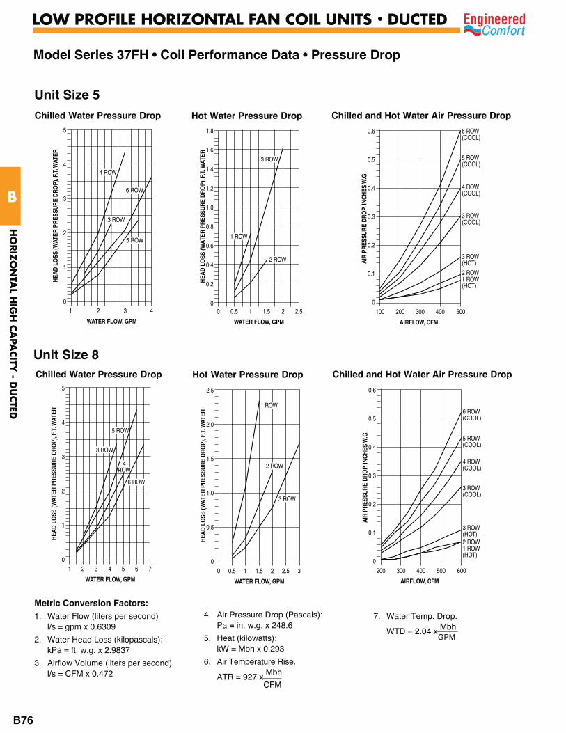
Model Series 37FH • Coil Performance Data • Pressure DropHE
AD L
OSS
(WAT
ER P
RESS
URE
DRO
P), F
.T. W
ATER
1 2 3 4
WATER FLOW, GPM
5
4
3
2
1
0
4 ROW
5 ROW
6 ROW
3 ROW
Chilled Water Pressure Drop
Unit Size 5
HEAD
LO
SS (W
ATER
PRE
SSUR
E DR
OP)
, F.T
. WAT
ER
0 0.5 1 1.5 2 2.5
WATER FLOW, GPM
1.8
1.6
1.4
1.2
1.0
0.8
0.6
0.4
0.2
0
1 ROW
2 ROW
3 ROW
Hot Water Pressure Drop
100 200 300 400 500
0.6
0.5
0.4
0.3
0.2
0.1
0
6 ROW(COOL)
2 ROW1 ROW(HOT)
5 ROW(COOL)
3 ROW(COOL)
4 ROW(COOL)
3 ROW(HOT)AI
R PR
ESSU
RE D
ROP,
INCH
ES W
.G.
AIRFLOW, CFM
Chilled and Hot Water Air Pressure Drop
HEAD
LO
SS (W
ATER
PRE
SSUR
E DR
OP)
, F.T
. WAT
ER
1 2 3 4 5 6 7
WATER FLOW, GPM
5
4
3
2
1
0
4ROW
5 ROW
6 ROW
3 ROW
Chilled Water Pressure Drop
Unit Size 8
HEAD
LO
SS (W
ATER
PRE
SSUR
E DR
OP)
, F.T
. WAT
ER
0 0.5 1 1.5 2 2.5 3
WATER FLOW, GPM
2.5
2.0
1.5
1.0
0.5
0
1 ROW
2 ROW
3 ROW
Hot Water Pressure Drop
200 300 400 500 600
0.6
0.5
0.4
0.3
0.2
0.1
0
6 ROW(COOL)
2 ROW1 ROW(HOT)
5 ROW(COOL)
3 ROW(COOL)
4 ROW(COOL)
3 ROW(HOT)
AIR
PRES
SURE
DRO
P, IN
CHES
W.G
.
AIRFLOW, CFM
Chilled and Hot Water Air Pressure Drop
Metric Conversion Factors:1. Water Flow (liters per second)
l/s = gpm x 0.6309
2. Water Head Loss (kilopascals): kPa = ft. w.g. x 2.9837
3. Airflow Volume (liters per second) l/s = CFM x 0.472
4. Air Pressure Drop (Pascals): Pa = in. w.g. x 248.6
5. Heat (kilowatts): kW = Mbh x 0.293
6. Air Temperature Rise.
ATR = 927 x Mbh CFM
7. Water Temp. Drop.
WTD = 2.04 x Mbh GPM
HO
RIZ
ON
TAL H
IGH
CA
PACITY
- DU
CTED
B
LOW PROFILE HORIZONTAL FAN COIL UNITS • DUCTED
B76

Model Series 37FH • Coil Performance Data • Pressure DropHE
AD L
OSS
(WAT
ER P
RESS
URE
DRO
P), F
.T. W
ATER
2 4 6 8 10 12
WATER FLOW, GPM
20
18
16
14
12
10
8
6
4
2
0
4ROW
5 ROW
6 ROW
3 ROW
Chilled Water Pressure Drop
Unit Size 12
HEAD
LO
SS (W
ATER
PRE
SSUR
E DR
OP)
, F.T
. WAT
ER
0 1 2 3 4 5
WATER FLOW, GPM
7
6
5
4
3
2
1
0
1 ROW
2 ROW
3 ROW
Hot Water Pressure Drop
400 600 800 1000 1200 1400
0.7
0.6
0.5
0.4
0.3
0.2
0.1
0
6 ROW(COOL)
2 ROW1 ROW(HOT)
5 ROW(COOL)
3 ROW(COOL)
4 ROW(COOL)
3 ROW(HOT)
AIR
PRES
SURE
DRO
P, IN
CHES
W.G
.
AIRFLOW, CFM
Chilled and Hot Water Air Pressure Drop
Metric Conversion Factors:1. Water Flow (liters per second)
l/s = gpm x 0.6309
2. Water Head Loss (kilopascals): kPa = ft. w.g. x 2.9837
3. Airflow Volume (liters per second) l/s = CFM x 0.472
4. Air Pressure Drop (Pascals): Pa = in. w.g. x 248.6
5. Heat (kilowatts): kW = Mbh x 0.293
6. Air Temperature Rise.
ATR = 927 x Mbh CFM
7. Water Temp. Drop.
WTD = 2.04 x Mbh GPM
HO
RIZ
ON
TAL H
IGH
CA
PACITY
- DU
CTED
B
LOW PROFILE HORIZONTAL FAN COIL UNITS • DUCTED
B77
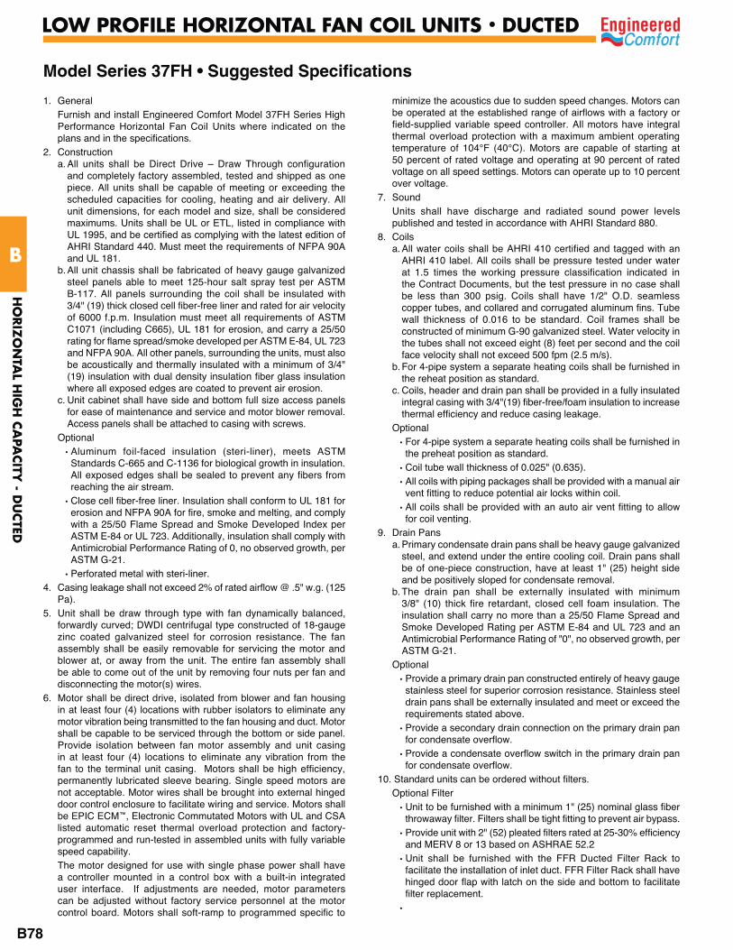
Model Series 37FH • Suggested Specifications
1. General Furnish and install Engineered Comfort Model 37FH Series High
Performance Horizontal Fan Coil Units where indicated on the plans and in the specifications.
2. Constructiona. All units shall be Direct Drive – Draw Through configuration
and completely factory assembled, tested and shipped as one piece. All units shall be capable of meeting or exceeding the scheduled capacities for cooling, heating and air delivery. All unit dimensions, for each model and size, shall be considered maximums. Units shall be UL or ETL, listed in compliance with UL 1995, and be certified as complying with the latest edition of AHRI Standard 440. Must meet the requirements of NFPA 90A and UL 181.
b. All unit chassis shall be fabricated of heavy gauge galvanized steel panels able to meet 125-hour salt spray test per ASTM B-117. All panels surrounding the coil shall be insulated with 3/4" (19) thick closed cell fiber-free liner and rated for air velocity of 6000 f.p.m. Insulation must meet all requirements of ASTM C1071 (including C665), UL 181 for erosion, and carry a 25/50 rating for flame spread/smoke developed per ASTM E-84, UL 723 and NFPA 90A. All other panels, surrounding the units, must also be acoustically and thermally insulated with a minimum of 3/4" (19) insulation with dual density insulation fiber glass insulation where all exposed edges are coated to prevent air erosion.
c. Unit cabinet shall have side and bottom full size access panels for ease of maintenance and service and motor blower removal. Access panels shall be attached to casing with screws.
Optional • Aluminum foil-faced insulation (steri-liner), meets ASTM
Standards C-665 and C-1136 for biological growth in insulation. All exposed edges shall be sealed to prevent any fibers from reaching the air stream.
• Close cell fiber-free liner. Insulation shall conform to UL 181 for erosion and NFPA 90A for fire, smoke and melting, and comply with a 25/50 Flame Spread and Smoke Developed Index per ASTM E-84 or UL 723. Additionally, insulation shall comply with Antimicrobial Performance Rating of 0, no observed growth, per ASTM G-21.
• Perforated metal with steri-liner.4. Casing leakage shall not exceed 2% of rated airflow @ .5" w.g. (125
Pa). 5. Unit shall be draw through type with fan dynamically balanced,
forwardly curved; DWDI centrifugal type constructed of 18-gauge zinc coated galvanized steel for corrosion resistance. The fan assembly shall be easily removable for servicing the motor and blower at, or away from the unit. The entire fan assembly shall be able to come out of the unit by removing four nuts per fan and disconnecting the motor(s) wires.
6. Motor shall be direct drive, isolated from blower and fan housing in at least four (4) locations with rubber isolators to eliminate any motor vibration being transmitted to the fan housing and duct. Motor shall be capable to be serviced through the bottom or side panel. Provide isolation between fan motor assembly and unit casing in at least four (4) locations to eliminate any vibration from the fan to the terminal unit casing. Motors shall be high efficiency, permanently lubricated sleeve bearing. Single speed motors are not acceptable. Motor wires shall be brought into external hinged door control enclosure to facilitate wiring and service. Motors shall be EPIC ECM™, Electronic Commutated Motors with UL and CSA listed automatic reset thermal overload protection and factory-programmed and run-tested in assembled units with fully variable speed capability.
The motor designed for use with single phase power shall have a controller mounted in a control box with a built-in integrated user interface. If adjustments are needed, motor parameters can be adjusted without factory service personnel at the motor control board. Motors shall soft-ramp to programmed specific to
minimize the acoustics due to sudden speed changes. Motors can be operated at the established range of airflows with a factory or field-supplied variable speed controller. All motors have integral thermal overload protection with a maximum ambient operating temperature of 104°F (40°C). Motors are capable of starting at 50 percent of rated voltage and operating at 90 percent of rated voltage on all speed settings. Motors can operate up to 10 percent over voltage.
7. Sound Units shall have discharge and radiated sound power levels
published and tested in accordance with AHRI Standard 880. 8. Coils
a. All water coils shall be AHRI 410 certified and tagged with an AHRI 410 label. All coils shall be pressure tested under water at 1.5 times the working pressure classification indicated in the Contract Documents, but the test pressure in no case shall be less than 300 psig. Coils shall have 1/2" O.D. seamless copper tubes, and collared and corrugated aluminum fins. Tube wall thickness of 0.016 to be standard. Coil frames shall be constructed of minimum G-90 galvanized steel. Water velocity in the tubes shall not exceed eight (8) feet per second and the coil face velocity shall not exceed 500 fpm (2.5 m/s).
b. For 4-pipe system a separate heating coils shall be furnished in the reheat position as standard.
c. Coils, header and drain pan shall be provided in a fully insulated integral casing with 3/4"(19) fiber-free/foam insulation to increase thermal efficiency and reduce casing leakage.
Optional• For 4-pipe system a separate heating coils shall be furnished in
the preheat position as standard. • Coil tube wall thickness of 0.025" (0.635).• All coils with piping packages shall be provided with a manual air
vent fitting to reduce potential air locks within coil.• All coils shall be provided with an auto air vent fitting to allow
for coil venting.9. Drain Pans
a. Primary condensate drain pans shall be heavy gauge galvanized steel, and extend under the entire cooling coil. Drain pans shall be of one-piece construction, have at least 1" (25) height side and be positively sloped for condensate removal.
b. The drain pan shall be externally insulated with minimum 3/8" (10) thick fire retardant, closed cell foam insulation. The insulation shall carry no more than a 25/50 Flame Spread and Smoke Developed Rating per ASTM E-84 and UL 723 and an Antimicrobial Performance Rating of "0", no observed growth, per ASTM G-21.
Optional• Provide a primary drain pan constructed entirely of heavy gauge
stainless steel for superior corrosion resistance. Stainless steel drain pans shall be externally insulated and meet or exceed the requirements stated above.
• Provide a secondary drain connection on the primary drain pan for condensate overflow.
• Provide a condensate overflow switch in the primary drain pan for condensate overflow.
10. Standard units can be ordered without filters. Optional Filter
• Unit to be furnished with a minimum 1" (25) nominal glass fiber throwaway filter. Filters shall be tight fitting to prevent air bypass.
• Provide unit with 2" (52) pleated filters rated at 25-30% efficiency and MERV 8 or 13 based on ASHRAE 52.2
• Unit shall be furnished with the FFR Ducted Filter Rack to facilitate the installation of inlet duct. FFR Filter Rack shall have hinged door flap with latch on the side and bottom to facilitate filter replacement.
•
HO
RIZ
ON
TAL H
IGH
CA
PACITY
- DU
CTED
B
LOW PROFILE HORIZONTAL FAN COIL UNITS • DUCTED
B78

Model Series 37FH • Suggested Specifications (continued)
11. Electrical Units shall be furnished with a hinged door control enclosure and
wired single point power connection. All power and control wiring shall conform to National Electric Code Standards. Within the control enclosure it shall include all required devices, including but not limited to, service switch, relay, control power transformers and control packages, low voltage remote shutdown relays, etc.
12. Electric heat a. Furnish an electric resistance heating assembly as an integral
part of the fan coil unit, with the heating capacity, voltage and kilowatts scheduled. The heater assembly shall be designed and rated for installation on the fan coil unit and be located in the unit as to not expose the fan assembly to excessive leaving air temperatures that could affect motor performance.
b. The heater and unit assembly shall be listed for zero clearance and meet all NEC requirements, and be ETL listed with the unit as an assembly in compliance with UL 1995. A NEMA 1 enclosure with hinges shall be placed at the side of the fan coil to provide easy access. All motor wiring and heater terminates in the enclosure for single point electrical connection.
c. All heating elements shall be open coil high grade Class A 80/20 nickel/chrome element wire mounted in ceramic insulators and located in an insulated heavy gauge galvanized steel housing. All elements shall terminate in a machine staked stainless steel terminal secured with stainless steel hardware for corrosion resistance. The element support brackets shall be spaced no greater than 3-1/2" (89) on center. All internal wiring shall be rated for 221°F (105°C) minimum. All heaters shall include over temperature protection consisting of an automatic reset primary thermal limit. All heaters shall be single stage unless noted otherwise on the plans. All units with electric heat shall be provided with an incoming line power distribution block, designated to accept single point power wiring capable of carrying 125% of the calculated load current.
d. A Class 2 transformer shall be provided for low voltage control. All devices shall be serviceable through the hinged enclosure and without removing heating element from the unit.
Optional• Heating coils shall be controlled with the SCR option and
proportional control to provide infinite heater control.• 2 Stage Electric Heat shall be provided.• Toggle Disconnect.• Door Interlocking disconnect switch.• Quieter operation option available.• Power circuit fusing.
Dust tight control enclosure.• Manual reset secondary high limit.• Positive pressure air flow switch.• Electronic air proofing with EPIC ECM.
13. Piping – Valve Packages As optional
• Provide a factory assembled and installed valve piping package in a fully insulated integral casing with 3/4" (19) fiber-free/foam insulation to increase thermal efficiency and reduce casing leakage. Valve package shall consist of a 2 or 3 way, on/off, motorized electric control valve and two ball isolation valves. Maximum entering water temperature on the control valve shall be 200°F (93.3°C) with a maximum operating pressure of 300 PSIG. Refer to Specification Section titled, "Pipes, Valves, Fittings and Accessories" for optional and accessories specifications.
• Provide modulating control valve (fail-in-place) in lieu of standard 2-position control valve with factory assembled valve piping package.
• Provide a fixed-auto flow control device for each piping package with the specific gpm specified for the unit on the schedule.
• Provide an adjustable flow control device for each piping package.
• Provide unions and/or pressure/temperature ports for each piping package.
14. Ultraviolet Light As optional each unit shall be supplied with Ultraviolet Lights
for disinfection for HVAC mold, bacteria & odor control. Fixture assembly to be installed at the coil discharge (downstream of the coil), between the coil and fan housing. Fixtureless lamps are to be installed in sufficient quantity and in such a manner so as to provide an equal distribution of UVC energy. The minimal UVC energy striking a surface shall be sufficient to continuously destroy a monolayer of mold and bacteria in less than six hours when at 55-135°F (12.7-57°C). Fixture shall be electrically terminated to within factory supplied ballast housings to meet NEC and local codes. Lamps shall be mounted to irradiate the intended surface(s) as well as all of the available line of sight airstream by proper placement and incident angle reflection.
To protect maintenance personnel, all access panels and doors to the UVC assembly and/or within view of the UVC assembly must include mechanical interlock switch(es) to insure that the UVC assembly will be de-energized when any of these accesses are opened. For complete safety, the UVGI equipment shall have been tested, Listed and labeled as an integral part of the fan coil unit by the fan coil manufacturer, no exceptions.
15.Controls Controller and sensors provided by others but mounted and wired
during unit assembly at the fan coil manufacturing facility.
HO
RIZ
ON
TAL H
IGH
CA
PACITY
- DU
CTED
B
LOW PROFILE HORIZONTAL FAN COIL UNITS • DUCTED
B79

HO
RIZ
ON
TAL H
IGH
CA
PACITY
- DU
CTED
B
LOW PROFILE HORIZONTAL FAN COIL UNITS • DUCTED
B80
NOTES:


![Job Name: Location: Date: Purchaser: Engineer: …...SEZ-KD09,12,15,18NA (For data on specific indoor units [all ducted, all non-ducted, and both ducted and non-ducted] combinations,](https://img.dokumen.tips/doc/110x75/5f3ef44adb4c0539d030f3d9/job-name-location-date-purchaser-engineer-sez-kd09121518na-for-data.jpg)