Embed Size (px)
Citation preview

HONEYWELL SPYDER
1
Honeywell Spyder

HONEYWELL SPYDER
2
ContentsAbout Honeywell Spyder 6What’s new? ....................................................................................................... 6Abbreviations ...................................................................................................... 6Domain Dictionary................................................................................................ 6Scenarios ............................................................................................................ 7
Getting Started 8Installation ........................................................................................................... 8Migration ............................................................................................................. 10
Programming Honeywell Spyder 12Downloading Application Logic ........................................................................... 12Updating Modules ............................................................................................... 12Error View on LonSpyder device ......................................................................... 13Error View on BacnetSpyder device ................................................................... 14ControlProgram Details View .............................................................................. 15Controller Summary View ................................................................................... 16ControlProgram NV Configuration View ............................................................. 17Viewing the List of Network Variables ................................................................. 17Group as NV ....................................................................................................... 17Bacnet Object Configuration View ...................................................................... 18Viewing the List of Bacnet Objects ..................................................................... 18ControlProgram Wiresheet View ......................................................................... 18Designing The Application Logic ......................................................................... 19ControlProgram Resource Usage View .............................................................. 19ControlProgram Resource Usage ....................................................................... 19ControlProgram Terminal Assignment View ....................................................... 20Macro Details View ............................................................................................. 20Macro Resource Usage View ............................................................................. 21Macro Wiresheet View ........................................................................................ 21Application Details View ...................................................................................... 21Application Programming View ........................................................................... 21Application Resource Usage View ...................................................................... 21Application NV Configuration View ..................................................................... 22Viewing the List of Network Variables ................................................................. 22Application Bacnet Object Configuration View .................................................... 22Viewing the List of Bacnet Objects ..................................................................... 23Actions on BacnetSpyder explained ................................................................... 23
Physical Points 25Binary Inputs ....................................................................................................... 25Binary Outputs .................................................................................................... 27Modulating Inputs ................................................................................................ 29Modulating Outputs ............................................................................................. 33
Software Points 37Constants ............................................................................................................ 37Network Inputs .................................................................................................... 38Network Setpoints................................................................................................ 40Network Outputs ................................................................................................. 42
Editing Software Points 45Network Input ...................................................................................................... 45Network Setpoint ................................................................................................ 45Constant .............................................................................................................. 46Network Output ................................................................................................... 46
Network Variables 47Viewing the List of Network Variables ................................................................. 47Group NVs .......................................................................................................... 48Network Variable Input ........................................................................................ 49Network Configuration Input ............................................................................... 52Many To One NV ................................................................................................ 55Network Variable Output ..................................................................................... 56Edit Network Variables ........................................................................................ 60

HONEYWELL SPYDER
3
Invalid Points ....................................................................................................... 63
Bacnet Objects 65Viewing the List of Bacnet Objects ..................................................................... 66Object Input ........................................................................................................ 66Object Setpoint ................................................................................................... 67Object Output ...................................................................................................... 68Edit Objects ......................................................................................................... 69
Bindings or Data Sharing 73Binding Lon Devices ........................................................................................... 73Binding Bacnet Devices ...................................................................................... 73About Bacnet Link Manager ............................................................................... 73Add Bindings ....................................................................................................... 75Binding Jace and Spyder .................................................................................... 75
Flow Calibration 77Pre-requisites ...................................................................................................... 77
Function Blocks 80Add Device ......................................................................................................... 80Add Function Block ............................................................................................. 80Configure Function Block .................................................................................... 80Delete Function Block ......................................................................................... 80
Analog Function Blocks 81Analog Latch ....................................................................................................... 81Average ............................................................................................................... 83Compare ............................................................................................................. 84Encode ................................................................................................................ 85Hysteretic Relay .................................................................................................. 88Maximum ............................................................................................................ 89Minimum ............................................................................................................. 90Priority Select ...................................................................................................... 91Select .................................................................................................................. 93Switch ................................................................................................................. 94
Built In Function Blocks 95Schedule ............................................................................................................. 95Conventional Wall Module .................................................................................. 97SBus wall module ............................................................................................... 98Configuring S-Bus wall module ........................................................................... 99
Control Function Blocks 116AIA ...................................................................................................................... 116Cycler .................................................................................................................. 118Cycler Functionality ............................................................................................. 119Stager Functionality ............................................................................................ 120Flow Control ........................................................................................................ 121PID ...................................................................................................................... 123Rate Limit ............................................................................................................ 125Stager .................................................................................................................. 126Cycler Functionality ............................................................................................. 127Stager Functionality ............................................................................................ 128Stage Driver ........................................................................................................ 129
Data Function Blocks 132Counter ............................................................................................................... 134Override .............................................................................................................. 136Priority Override .................................................................................................. 137Runtime Accumulate ........................................................................................... 139
Logic Function Blocks 141AND .................................................................................................................... 141Oneshot .............................................................................................................. 142OR ...................................................................................................................... 144XOR .................................................................................................................... 145

HONEYWELL SPYDER
4
Math Function Blocks 146Add ..................................................................................................................... 146Digital Filter ......................................................................................................... 147Divide .................................................................................................................. 148Enthalpy .............................................................................................................. 149Exponential ......................................................................................................... 150Flow Velocity ....................................................................................................... 151Limit .................................................................................................................... 152Multiply ................................................................................................................ 153Ratio ................................................................................................................... 154Reset .................................................................................................................. 156Square Root ........................................................................................................ 158Subtract .............................................................................................................. 159
Zone Arbitration Function Blocks 160General Set Point Calculator .............................................................................. 160Occupancy Arbitrator .......................................................................................... 163Set Temperature Mode ........................................................................................ 167Temperature Set Point Calculator ....................................................................... 171
Pass Thru 176
Calibrate sensors 177Pre-requisites ...................................................................................................... 177
Diagnose Outputs 178Pre requisites ...................................................................................................... 178Diagnose Outputs for a Lon Device .................................................................... 178Diagnose Outputs for a Bacnet Device ............................................................... 178
Macros 180
Spyder Library 181Open Spyder Library ........................................................................................... 182Close Spyder Library .......................................................................................... 182Add Items to Spyder Library ............................................................................... 182Saving Library Items ........................................................................................... 183Load Library Item ................................................................................................ 184Delete Library items ............................................................................................ 185Export Library Items ............................................................................................ 186Import items to Library ........................................................................................ 186Spyder Library Applications ................................................................................ 186
Modes of Operation 189Accessing Different Modes ................................................................................. 189
Engineering Mode 190
Online Debugging Mode 191
Force Values 209Actions ................................................................................................................ 210
Select Points to Debug 211
Simulation 212Example Scenario ............................................................................................... 214
Simulation Settings 229Time Simulation .................................................................................................. 229Continuous Simulation ........................................................................................ 229Step Simulation ................................................................................................... 229Force Values ....................................................................................................... 230Actions ................................................................................................................ 232Select Points to Display in Simulation Log Window ............................................ 232
Generate XIF File 234

HONEYWELL SPYDER
5
Order Of Execution 235
Custom Palette File 236Create Custom Palette File ................................................................................. 236Add Items to Custom Palette File ....................................................................... 237Close Custom Palette File .................................................................................. 237Add Device to Custom Palette File ..................................................................... 237
Device Icons 238Lon Icons ............................................................................................................ 238Bacnet Icons ....................................................................................................... 238Device Icons in Library ........................................................................................ 238
Virtual Offline Discovery 239

HONEYWELL SPYDER
6
ABOUT HONEYWELL SPYDERThis document serves as a guide to configure and use the Honeywell Spyder Tool. The Honeywell Spyder Tool is an add-on module to the existing Niagara framework modules. It provides a graphical environment to program Honeywell Spyder Controllers.
It provides the following features:
• Graphical environment to program a Honeywell Spyder controller
• Libraries of function blocks to create an application logic • Calibration of inputs, and diagnostics of outputs • Offline simulation • Online debugging
What’s new?The LonSpyder I models support 100 Function blocks whereas the Spyder II, Spyder Micro, and BacnetSpyder models support 200 function blocks. Also, the Spyder II and Spyder Micro models support 220 Network Variables.
LonSpyder models include:
Spyder I models:
• PVL6436A • PVL6438N • PUL6438 Spyder II models:
• PVL6436AS • PVL6438NS • PUL6438S Spyder Micro models:
• PVL4024NS • PVL4022AS • PUL4024S • PUL1012S • PVL0000AS BacnetSpyder models include:
• PVB6436AS • PVB6438NS • PUB6438S To migrate from a LonSpyder I model to a LonSpyder II or Spyder Micro, you must simply replace the existing Spyder controller in the field with the new controller. A new neuron ID is assigned to the Spyder II and Spyder Micro device in station. Select the new model in the tool and download it to the new controller.
The tool now supports LonSpyder Micro models.
You can configure the physical inputs of a Micro model to be used as Pulse Meter or Counter types or Momentary type binary inputs.
Support of Bacnet Spyder device is major enhancement in the tool.
The following sequence of operations can be performed on a Bacnet Spyder controller.
1. Set up BacnetSpyder controllers on the network2. Create applications to program the controller3. Simulate the applications you have created4. Download the configuration to the controller5. Debug the applications6. Set up offline data sharing links and download to the
controllers7. Perform online operations like sensor calibration, Con-
troller diagnostics, flow balancing, and so on.
The Lon models, Spyder II and Spyder Micro support configuring the S-Bus (Sylk-Bus) wall module (2-wire wall module) in addition to the conventional wall module (7-wire). You can connect the Kingfisher wall module to the controller, use the Spyder tool to configure it by using the S-Bus wall module function block, save the changes, and download it to the LonSpyder controller. The BacnetSpyder models are configured with an SBus wall module.
You can upload the changes made in the settings on the wall module display, to the Spyder controller using the tool. You can also simulate the S-Bus wall module logic using the Simulation feature. The S-Bus wall module configuration can be stored in the Spyder library and can be reused across applications.
The Quick Download allows you to download only the changed configuration to the database.
The following function blocks have the Ignore invalid input parameter to specify behavior of invalid inputs:
• Minimum • Maximum • Average • Add • Multiply • Divide • Subtract• Ratio With this option, you can configure the function block to ignore any invalid inputs, and consider only the valid inputs to calculate the output. If this option is left selected, the invalid inputs make the output also invalid.
Abbreviations • JACE: Java Application Control Engine • NRE: Niagara Runtime Environment • JVM: Java Virtual Machine• NV: Network Variable
Domain Dictionary 1. JACE: Java Application Control Engine. The Tridium-
manufactured controller that runs the core runtime Nia-gara software in a JVM, providing a station with the direct support for field device integration and enterprise LAN connectivity.
2. Fox: This is Tridium’s proprietary protocol for communi-cation between workbench and the station.

HONEYWELL SPYDER
7
3. Host: The host is a hardware platform or computer on which the Niagara software runs. Niagara can run on a computer or a JACE controller.
4. Station: The Niagara station is a JVM that hosts the run-ning of objects.
5. Commission: This is the process of downloading the application (program logic + network image) to the Hon-eywell Spyder controller.
6. Functional blocks: Functional blocks are the atomic pro-gram objects that define a specific function.
7. Macros: Macros are a set of functional blocks that define a specific functionality.
8. Wiresheet: Wiresheet is the view in the Niagara work-bench that allows you to drag and drop functional blocks and macros to define application logic.
9. Programming environment/Graphical environment: A wiresheet view that allows you to define your application logic for the Honeywell Spyder controller.
10. Application: An Application is a group of function blocks that are interconnected to form control logic. This appli-cation is then downloaded to the controller to run the control logic in the controller.
ScenariosThe Honeywell Spyder Tool provides the programming environment for the Honeywell Spyder controllers. It is developed with using Niagara AX framework developed by Tridium and runs in the Niagara Runtime environment.
The Honeywell Spyder Tool can be used to program the Spyder controller in the following two ways:
• Through JACE
JACE (Java Application Control Engine) controller bundles the software capability of the framework in a hardware platform. JACEs connect to system field buses on the other end and provide real time control functions. Honeywell Spyder Tool can be hosted on a computer loaded with Niagara AX framework as well as JACE. JACE is loaded with the framework, the station database, and all the modules available in the computer. The Honeywell Spyder Tool communicates with the Honeywell Spyder controller through JACE. JACE is connected to the same LAN as the PC and communicates to the Honeywell Spyder Tool on Fox Protocol (on LAN). On the other end, it communicates to the Honeywell Spyder controller on the Lon bus.
The workbench in the computer also communicates with the JACE by dialing into the onboard modem of the JACE. However, this can be a slow connection.
• Through Engineering computer In this case, the Niagara AX framework runs on the computer. The computer connects to the system field buses directly through the appropriate network interface. This is the soft JACE option.
The Honeywell Spyder Tool can be hosted on a computer loaded with Niagara AX framework. The station database resides on the same computer and connects to the Honeywell Spyder controller on the Lon Network using the PCLTA/PCMCIA card or through SLTA.
Station databases are typically engineered on the engineering computer (this is called Offline Mode), then installed to a JACE and its associated Web Supervisor computer, if any.

HONEYWELL SPYDER
8
GETTING STARTED
InstallationThis release contains three flavours of the Spyder tool:
• Lon and Bacnet• Lon only• Bacnet only
Upgrading Soft JACEYou must stop the stations running on your PC and close the workbench before you start upgrading the soft JACE.
1. Depending on the flavor of the tool being installed, copy the dist file and the corresponding batch file to any folder in your PC. The following is the list of available dist files and their corresponding batch files.
— dist_PC_Lon_Bacnet_Spyder.dist; PC_Split_Installer_Lon_Bacnet.bat1
— dist_PC_Bacnet_Spyder.dist; PC_Split_Installer_Bacnet.bat1
— dist_PC_Lon_Spyder.dist; PC_Split_Installer_Lon.bat1
2. Locate a file with extension .bat1 in installation of a given flavor of the tool and rename it to .bat extension.
3. Double-click on the batch file(.bat file). This opens the command prompt prompting for Niagara Home Path.
4. Type the folder path where Niagara is installed in your PC. For example, D:\Honeywell\WEBPro-AX-3.4.43. The installer then prompts for Niagara Platform Creden-tials.
5. Type the User Name and Password to connect to the Niagara Platform. After the Platform authentication succeeds, the dist file installer proceeds to install the required modules. Once the installation is complete, a confirmation message is displayed on the console.
6. Press any key to close the console.
NOTE: Existing applications created with earlier versions of the tool need to be migrated using Spyder Migration tool to be compatible with the current version of the tool. See Using Spyder Migration Utility section for information on the migration procedure.
Upgrading Hard JACEYou must stop the station running on the JACE and start the workbench before you start upgrading the hard JACE.
1. Select one of the following dist files.— dist_JACE_Bacnet_Spyder.dist— dist_JACE_Lon_Bacnet_Spyder.dist— dist_JACE_Lon_Spyder.dist
2. Run the file using Niagara Platform’s Distribution File Installer option. The Distribution File Installer installs the required modules in the JACE.
NOTE: Existing applications created with earlier versions of the tool need to be migrated using Spyder Migration tool to be compatible with the current version of the tool.
After installing the new tool version in the JACE, you can migrate the existing Spyder applications in the JACE using the following procedure.
1. Copy the station running in the JACE to your local PC using the Station Copier option available in the Plat-form options of the JACE.
2. Migrate the copied JACE station using the Spyder Migrator tool. See Using Spyder Migration Utility section for information on Spyder Migration tool.
3. Copy the migrated station back to the JACE using the Station Copier option and restart the JACE.
Using Spyder Migration UtilityDifferent migration utilities have been provided for different flavors of the tool.
1. Lon and Bacnet : honeywellSpyderMigrator.jar2. Bacnet only : honeywellBSMigrator.jar3. Lon only: honeywellLSMigrator.jar
The dist file installers install the appropriate migration utility.
To migrate the existing applications:
1. Launch the workbench after installing the migration tool through the dist file.
2. Browse to the migration utility on the main menu of the workbench as shown in the image..
3. Click the migration utility option from the list. The follow-ing screen is displayed. The tool allows you to migrate various types of databases.
]

HONEYWELL SPYDER
9
4. Select the File Type and then select the Niagara Home Directory where that particular database is stored. The tool automatically lists all the files of the selected file type available in the directory, as shown in the screen-shot.
5. Select the files to be migrated and click Migrate. 6. Once the migration is completed, click Close to close
the migration utility window.
The tool automatically moves the selected existing stations to a folder called LegacyStations. The migrated Stations are given the actual station name so that they are ready to be used. Similarly, the tool moves the existing Lexicon files to a folder called LegacyLexicons and it renames the migrated Lexicon files with the names of existing files.
For other file types, you can choose the Output directory where you want the migrated databases to be stored. By default the tool stores them in a folder by name Migrated<FileType> where FileType is the file type that you have selected for migration. This new directory is created under the input directory.
For example, if the file type selected for migration is of type SpyderLibrary, and the existing library is available in the location C:/Library, then the migrated libraries are stored in C:/Library/MigratedLibraries.
NOTE: If you are a first time user, follow the procedures to Launch the workbench, Add new station, Start the station, Add a network, and Add a controller.
NOTE: If you are an existing user and would like to migrate from an existing Spyder controller to a new Spyder controller, see the Migration section.
Launching the Workbench• Click Start > Programs > Niagara > Workbench to launch
the workbench.
Adding New StationOn the Workbench:
1. Click Tools > New Station. The New Station Wizard appears.
2. Type the Station Name.
3. The Station Directory path is updated with the name you just entered and displays the location where the files are stored. Click Next.
4. Type a password in the Admin Password field. 5. Re-type the same password in the Admin Password
Confirm field. 6. Click Finish to complete adding a station. The station is
added and the Property Sheet of the station is dis-played on the right portion of your screen.
Starting the Station 1. On the Nav palette, click Platform. The Authentication
dialog box appears.
NOTE: If the Nav palette is not visible on the left pane, from the Menu bar, select Window > Sidebars > Nav to display the Nav palette.
2. Type the User Name, Password, and click OK. The right portion of your screen displays a list of object names and their description.
3. Double-click Application Director. The list of available stations appears.
4. Select the station you have added and click Start. The station you have added appears in the Nav palette under Platform.
5. Double-click the Station option on the Nav palette. The Authentication dialog box appears.
6. Type the User Name and Password and click OK. The Station you have added is launched and the Station Summary Property view appears on the right portion of your screen.
Adding a Network To add a Lon Network:
1. Click Windows > Side Bars > Palette to add the pal-ette named Palette if it is not visible on the left pane.
2. Click the Open Palette button on the Palette. The Open Palette dialog box appears.
3. Select Lonworks from the list if available and click OK. or Click Browse and select the location this folder is stored and click OK.
4. Expand Config in the Nav palette to display Drivers. 5. Select LonNetwork from the Palette and drag it on
Drivers in the Nav palette. 6. Type a name for the Lon Network you are adding and
click OK. Expand Drivers and verify to see that the Lon Network is added.
To add a BACnet Network:
1. Click Windows > Side Bars > Palette to add the pal-ette named Palette if it is not visible on the left pane.
2. Click the Open Palette button on the Palette. The Open Palette dialog box appears.
3. Select bacnet from the list if available and click OK. or Click Browse and select the location this folder is stored and click OK.
4. Expand Config in the Nav palette to display Drivers. 5. Select BacnetNetwork from the Palette and drag it on
Drivers in the Nav palette.

HONEYWELL SPYDER
10
6. Type a name for the BACnet Network you are adding and click OK.
7. Expand Drivers and verify to see that the BACnet Net-work is added.
Adding a ControllerTo add a Honeywell Spyder controller:
1. Click the Open Palette button on the Palette. The Open Palette dialog box appears.
2. Select honeywellSpyderTool from the list if available and click OK. or Click Browse and select the location this folder is stored and click OK.
3. Select LonSpyder from the Palette and drag it on Lon Network under Drivers in the Nav palette. or Select BacnetSpyder from the Palette and drag it on BacnetNetwork under Drivers in the Nav palette.
4. Type a name for the device you are adding and click OK. Expand the Lon Network or Bacnet Network and verify to see that the device is added.
Viewing/Modifying Controller Summary DetailsTo view or modify the summary details of the LonSpyder controller:
1. Double-click the device name in the Nav palette to dis-play the Controller Summary View on the right portion of your screen. Device Name is an editable field.
2. Click the drop-down menu to select a Device Model from the list.
3. Select Enable Daylight Savings option and specify the following information when the day light savings must come into effect:
— Start Month — End Month — Start Day — End Day
4. Click Save to save the changes made to the Controller Summary View.
To view or modify the summary details of the BacnetSpyder controller:
1. Double-click the device name in the Nav palette to dis-play the Controller Summary View on the right portion of your screen. Device Name is an editable field.
2. Click the drop-down menu to select a Device Model from the list.
3. Click the Set button to change the Global Update Rate.
NOTES: Setting the Global Update Rate changes all the indi-vidual update rates including the update rates for Network Input points, Analog Outputs, Binary Out-puts that are enabled for Fail Detect. Global Update Rate has a default value of 60 seconds. The value can range from 0-3600 seconds.
4. Click the Set button to change the Global Send Heart Beat.
NOTES: Global Send Heart Beat is set at the device level and the changes made to this value is applied auto-matically to all the objects. Global Send Heart Beat has a default value of 60 seconds. The value can range from 0-3600 seconds.
5. Select Enable Daylight Savings option and specify the following information when the day light savings must come into effect:
— Start Month — End Month — Start Day — End Day
6. Click Save to save the changes made to the Controller Summary View.
Migration
From Spyder II to Spyder MicroIf you want to migrate from any of the earlier LonSpyder models, that is, Spyder I (PVL6436A, PVL6438N, or PUL6438) and Spyder II ( PVL6436AS, PVL6438NS, or PUL6438S) to the latest Lon models supported by Spyder, that is Spyder Micro (PVL4024NS, PVL4022AS, PUL4024S, PUL1012S, or PVL0000AS), do the following:
1. Replace the existing Spyder controller in the field (could be any one of the Spyder I or Spyder II models) with the new Spyder Micro controller.
2. Right-click the Lon network in the Nav palette of the Spyder tool.
3. Select Views > Lon Device Manager. The list of con-trollers is displayed on the right portion of the screen.
4. Select the controller from the list and click Discover. The device appears under Discovered on the top por-tion of the screen.
5. Select the controller under Discovered and click Add to add the controller.
6. Click OK. 7. Click Match to match the neuron id of the field controller
with the device in station. 8. Select the new model you are migrating to in the Con-
troller Summary View (right-click device in the Nav palette and choose Views > Controller Summary View).
9. Load an application from the Spyder library. 10. Download the configuration to the new Spyder Micro
controller model by right-clicking the device and select-ing Actions > Download.
From LonSpyder to BacnetSpyderIf you want to migrate from any of the LonSpyder models (Spyder I, Spyder II, or Spyder Micro) to the Bacnet models (PVB6436AS, PVB6438NS, or PUB6438S) supported by Spyder, do the following:
1. Replace the existing LonSpyder controller in the field (could be any one of the Spyder I, Spyder II, or Spyder Micro models) with the new BacnetSpyder controller.
2. Right-click the Bacnet network in the Nav palette of the Spyder tool.
3. Select Views > Bacnet Device Manager. The list of controllers is displayed on the right portion of the screen.

HONEYWELL SPYDER
11
4. Select the controller from the list and click Discover. The device appears under Discovered on the top por-tion of the screen.
5. Select the controller under Discovered and click Add to add the controller.
6. Click OK. 7. Click Match to match the neuron id of the field controller
with the device in station. 8. Select the new model you are migrating to in the Con-
troller Summary View (right-click device in the Nav palette and choose Views > Controller Summary View).
9. Load an application from the Spyder library. 10. Download the configuration to the new Spyder Micro
controller model by right-clicking the device and select-ing Actions > Download.
You can use Bacnet Spyder in one of the following ways.
• Create a new application in the BacnetSpyder controller.• Convert an existing Lon Application to corresponding
Bacnet application.
To create a Bacnet Spyder application:
1. Drag a BacnetSpyder device to the station under a Bac-net Network.
2. Double-click the device you have added and right-click on it to choose Views > Controller Summary View.
3. Select a model from the list.4. Browse to the ControlProgram of the BacnetSpyder
device.5. Drag the required objects from honeywellSpyderTool
palette and create an application.6. Browse to Bacnet Device Manager view on Bacnet
Network and discover the online Bacnet Spyder devices.
7. Match the device in Niagara to appropriate discovered device.
NOTE: Alternately, instead of creating an application you can load a suitable application from Spyder library or from Standard Applications Library in palette.
8. Download the configuration to the online device using Download option on the device.
To use an existing Lon Application in a BacnetSpyder device:
1. Drag a BacnetSpyder device to the station under a Bac-net Network.
2. Double-click the device you have added and right-click on it to choose Views > Controller Summary View.
3. Select a model from the list.4. Browse to the ControlProgram of the BacnetSpyder
device.5. Drag an existing Lon Application from Spyder Library to
the Control Program under the BacnetSpyder device. The tool automatically creates a Bacnet interface for the
Lon application. ( If it is an application in library, the tool would have automatically created the Bacnet interface in library ). Review the Bacnet interface that the tool has created and make necessary changes, if any.
6. Browse to Bacnet Device Manager view on Bacnet Network and discover the online Bacnet Spyder devices.
7. Match the device in Niagara to appropriate discovered device
8. Download the configuration to the online device using Download option on the device.
From Conventional wall module to SBus wall module If you want to replace the existing conventional wall module (T7770) with the SBus wall module, do the following:
1. Replace the existing Spyder controller in the field (could be any of LonSpyder I models: PVL6436A, PVL6438N, or PUL6438 ) with a new LonSpyderII, or Spyder Micro, or BacnetSpyder controller.
2. Right-click the Lon or Bacnet network in the Nav palette of the Spyder tool.
3. Select Views > Lon Device Manager or Bacnet Device Manager. The list of controllers is displayed on the right portion of the screen.
4. Select the controller from the list and click Discover. The device appears under Discovered on the top por-tion of the screen.
5. Select the controller under Discovered and click Add to add the controller.
6. Click OK. 7. Click Match to match the neuron id of the field controller
with the device in station. 8. Select the new model you are migrating to in the Con-
troller Summary View (right-click device in the Nav palette and choose Views > Controller Summary).
9. Download the configuration to the new Spyder controller model.
10. Replace the existing wall module model to any one of the SBus wall module models (same as hardware attached).
11. Drag the ConventionalWallModule function block from the Palette onto the wiresheet of the controller.
12. Right-click the conventional wall module block and select Configure Properties. The General Settings dialog box appears.
13. Select LCD Display under Model Options on the dia-log box. This changes the wall module selection from Conventional to S-Bus wall module.
14. Make appropriate links in the wire sheet of the applica-tion logic where the wall module is being used.
15. Download the configuration to the controller.
NOTE: Make sure that the SBusWallModule should be assigned the same address using rotatory Address switch as defined in the SBus wall module function block in Station.

HONEYWELL SPYDER
12
PROGRAMMING HONEYWELL SPYDERThe Honeywell Spyder Tool offers a graphical environment to program the Honeywell Spyder controller. You can use the wiresheet view in the Engineering Mode to use Physical points, Software points, and function blocks to build an application in the ControlProgram. The Physical points, Software points, and function blocks can be accessed using the Palette. You can drag these items on to the wiresheet and connect them, based on your need, to develop your application logic. The logic that you create can then be stored in a Spyder Library for reuse. Once you are satisfied with the logic you have created, you can download the same to the controller. The logic thus created can be tested for correctness using the Simulation and Online Debugging modes.
NOTE: Changing NCI values, configuration of a Schedule block, or Daylight savings option, puts the application in a quick download pending state. As long as the application has been downloaded at least once to the controller, these changes only trigger a quick download to the controller.
Use the ControlProgram option to program the Honeywell Spyder tool. To do this:
• Expand LonSpyder or BacnetSpyder in the Nav palette and double-click ControlProgram to display the Wiresheet view.
• Display the Palette (From the Menu bar, select Window > Sidebars > Palette to display the Palette).
The Palette appears on the left pane with the following items:
• LonSpyder: This is a device that you can drag on to the LonNetwork in the Nav palette to create a new device.
NOTE: You cannot drop this on to the wiresheet of any macro or ControlProgram or Application.
• BacnetSpyder: This is a device that you can drag on to the BacnetNetwork in the Nav palette to create a new device.
NOTE: You cannot drop this on to the wiresheet of any macro or ControlProgram or Application.
Physical Points: Modulating and Binary Inputs or Outputs.
SoftwarePoints: Use this to create Network Input, Network Setpoints, or Network Output.
• Analog: Analog function blocks • Logic: Logic function blocks • Math: Math function blocks • Control: Control function blocks • DataFunction: Data Function function blocks • ZoneArbitration: Zone Arbitration function blocks • BuiltIn: BuiltIn function blocks • Macro: A Macro is a group of functional blocks grouped
together that define a specific functionality. Commonly used program elements can be defined as macros so that they could be reused across applications.
• Application: This includes macros and logic that you can define and use in applications.
• StandardApplications: Standard applications shipped by Honeywell which you can use to build application logic
You can drag any of these items on to the wiresheet of a ControlProgram in its Engineering Mode and make the connections between Physical points, Software points, and function blocks to create a ControlProgram or an Application.
Use this wiresheet view to drag the Physical points and Function blocks to build your application logic. You can save a logic you created to be used later and also share it with other users.You can build several applications and store them in a Spyder Library along with Honeywell supplied standard applications.
Downloading Application LogicAfter you have created your application logic and tested the logic using the simulation feature, you can download the application logic to the controller. To download the application logic:
1. On the Nav palette, right-click the device and select Actions > Download. The Download dialog box appears.
2. Select True under Full Download for a full download or False for a quick download.
NOTE: A Quick Download only downloads the modified items from a previous download where as with a Full Download the entire configuration is downloaded to the controller replacing the existing configuration. However, if changes have been made to the SBus wall module by an operator/tenant locally from the display on the wall module, and a full download is performed, Spyder tool downloads the entire configu-ration to the controller except the SBus wall module configuration. This is done to avoid losing any changes made locally on the SBus wall module dur-ing a download operation.
3. Click OK. The application logic is downloaded to the controller based on your selection.
NOTE: Make sure that if you are using the SBus wall module or the ignore invalid option for function block , the models selected are LonSpyder II, Spyder Micro, or BacnetSpyder. SBus wall module cannot be down-loaded to the LonSpyder I models.
When using Spyder II, Spyder Micro, or BacnetSpyder models, if you modify SBus wall module settings from the display in the wall module, you can also upload the same configuration into the Spyder tool.
Updating ModulesFollow this procedure to install updates of Standard Applications. This is the StandardApps.jar file you will receive that you will need to install to begin using the latest Standard Applications provided.

HONEYWELL SPYDER
13
1. Connect to the platform of the station. 2. Navigate to File transfer Client and transfer the Stan-
dardApps.jar file from the local drive to the modules folder of the Station.
3. Restart the workbench/webworkbench. 4. Expand StandardApplications in the Spyder palette.
The latest Standard Applications are displayed.
Error View on LonSpyder deviceThis view displays all the alarms generated by the Honeywell Spyder controller. There are 6 categories of alarms:
• Sensor Alarms: These alarms are generated for all the Sensors configured in the logic. All input blocks assigned to pins UI0 to UI6 are listed in this category.
• Invalid ConfigurationAlarms: This alarm occurs if there is an error in the configuration that was downloaded.
• Network Communication Alarms: These alarms occur ONLY for NVIs and Object inputs configured as fail detect. The network variable names are listed in this category.
• Control Alarms: All the alarm blocks configured in the logic are listed in this category. If an alarm block does not have any incoming link then the status is always NORMAL.
• S-BUS WM Communication Alarm: These alarm occur when the communication link between the SbusWallModule and the controller are lost.
• S-BUS WM Fail Detect Alarms:These alarms occurs for the linked outputs of the SBusWallmodule.All the linked outputs are listed in this category.
NOTE: The S-BUS WM Communication Alarm and the S-BUS WM Fail Detect Alarms are shown only for:
— Spyder II models: PVL6436AS, PVL6438NS, PUL6438S
— Spyder Micro models: PVL4024NS, PVL4022AS, PUL4024S, PUL1012S, PVL0000AS
To view the Alarms View of a controller, right-click the Device Name in the Nav palette and select Views > Alarms View. The Alarms view is displayed on the right half of the screen. The Alarms view is static and you must refresh the view to get the latest update.
nvoErrorThe Honeywell Spyder tool provides a multi-byte network variable, nvoError, which indicates errors. You can access the nvoError map on the Property Sheet view of the controller. The nvoError map consists of 10 fields of one byte each. As each byte is 8 bits long, there are a maximum of 80 bits that are used to indicate errors. Each bit is mapped to an alarm.
There are 6 categories of alarms:
NOTE: It is not necessary that two consecutive bits are filled during two consecutive alarm conditions. The tool allocates any bit position within the specified range. For example, in case of S-Bus WM Fail Detect Alarms in Spyder Micro, it is not necessary that the bit position 198 is filled and then 199 and so on. Hon-eywell Spyder allocates any bit position between 198 and 247.Similarly is the case for all the models in Network Communication Alarms, Control Alarms, and S-Bus WM Fail Detect Alarms.
Alarm Type DescriptionSensor Alarms Generated for all sensors configured in
the logic. All input blocks assigned to pins UI0 to UI6 are listed in this category.
Invalid Configuration Alarms
Occurs if there is an error in the configuration that was downloaded.
Network Communication Alarms
Occur ONLY for NVIs and Object Inputs configured as fail detect. The network variable or object input names are listed in this category. In the LonSpyder I and Spyder II models, you may define upto 32 input network variables with fail detect. On detection of an alarm condition, the LonSpyder I and Spyder II models fill a number between 16 and 47.In the Spyder Micro models, you may define upto 150 input network variables with fail detect. Spyder Micro models fill a number between 48 and 197.
Control Alarms All the alarm blocks configured in the logic are listed in this category. If an alarm block does not have any incoming link then the status is always NORMAL. You may define upto 32 alarm function blocks in LonSpyder I, Spyder II, andSpyder Micro models. On detection of an alarm condition, the LonSpyder I and Spyder II models fill a number between 48 and 79. Spyder Micro models fill a number between 16 and 47.
S-BUS WM Communication Alarm
These alarms occur when there is a communication break between the device and the wall module.
S-BUS WM Fail Detect Alarms
Shown only for LonSpyder II and Spyder Micro models. These alarms occur for the linked outputs of the SBusWallmodule. All the linked outputs are listed in this category. In the LonSpyder II models, you may define upto 168 alarm function blocks. On detection of an alarm condition, the LonSpyder II models fill a number between 80 and 247. In the Spyder Micro models, you may define upto 50 alarm function blocks. Spyder Micro models fill a number between 198 and 247.

HONEYWELL SPYDER
14
To view the Alarms View of a controller, right-click the Device Name in the Nav palette and select Views > Alarms View. The Alarms view is displayed on the right half of the screen. The Alarms view is static and you must refresh the view to get the latest update.
The following table indicates the bit positions and the alarms they are used to represent:
The range and bit positions differ for LonSpyder Micro. The following table indicates the bit positions for the Control Alarms, Network Communication Alarms, and S-Bus WM Fail Detect Alarms.
NOTE: UI 0 is displayed only for models that support UI 0. UI 7 is not shown on the Alarms View.
Error View on BacnetSpyder deviceThis view displays all the errors generated by the Honeywell Spyder controller. There are 6 categories of errors:
• Sensor Alarms: These errors are generated for all the Sensors configured in the logic. All input blocks assigned to pins UI0 to UI6 are listed in this category.
• Invalid Configuration Alarm: This alarm occurs if there is an error in the configuration that was downloaded.
• Network Communication Alarms: These errors occur ONLY for object inputs configured as fail detect. The object names are listed in this category.
• Control Alarms: All the alarm blocks configured in the logic are listed in this category. If an alarm block does not have any incoming link then the status is always NORMAL.
• S-BUS WM Communication Alarm: These alarm occur when the communication link between the SbusWallModule and the controller are lost.
• S-BUS WM Fail Detect Alarms: These alarms occurs for the linked outputs of the SBusWallmodule.All the linked outputs are listed in this category.
To view the Error View of a controller, right-click the Device Name in the Nav palette and select Views > Error View. The Error view is displayed on the right half of the screen. This view is static and you must refresh the view to get the latest update.
Error ObjectsThe Honeywell Spyder tool provides 248 error bits which indicates errors. Spyder Bacnet supports the 16 error objects, AV_Error0 to AV_Error15. Each error object is 16-bit long except for the 16th Error Object(AV_Error15) which is 8-bit long.
To access the error objects:
1. Expand the Bacnet device on the Nav sidebar. 2. Right-click Points and select Bacnet Spyder Point
Manager. 3. The Point Manager view appears on the right pane. 4. Click the Discover button to discover all the points on
the device.5. The points are listed under Discovered on the screen.
Bit Position Alarm Type Description0-7 Sensor Alarm Indicates error condition on
Modulating inputs or outputs.
0 Sensor Alarm The on-board pressure sensor is open or shorted.
1 Sensor Alarm Universal Input 1 exceeds the user defined range, that is, it is open or shorted.
2 Sensor Alarm Universal Input 2 exceeds the user defined range
3 Sensor Alarm Universal Input 3 exceeds the user defined range
4 Sensor Alarm Universal Input 4 exceeds the user defined range
5 Sensor Alarm Universal Input 5 exceeds the user defined range
6 Sensor Alarm Universal Input 6 exceeds the user defined range
7 Sensor Alarm Universal Input 7 exceeds the user defined range
8-14 No mapping The on-board thermistor is open or shorted
15 Invalid Configuration Alarm
The configuration downloaded to the controller is illegal. One or more file sections have a CRC error
16-47 Network Communication Alarm
The input network variable represented by this bit is not being received within the fail detect time
48-79 Control Alarm The alarm function block reporting the alarm represented by this bit.
80-247 S-BUS WM Fail Detect Alarms
The output of the S-Bus Wallmodule represented by this bit is not being received within the fail detect time.
Bit Position Alarm Type Description16-47 Control
AlarmThe alarm function block reporting the alarm represented by this bit.
48-197 Network Communication Alarm
The input network variable represented by this bit is not being received within the fail detect time.
198-247 S-BUS WM Fail Detect Alarms
The output of the S-Bus Wallmodule represented by this bit is not being received within the fail detect time.
HONEYWELL SPYDER
15
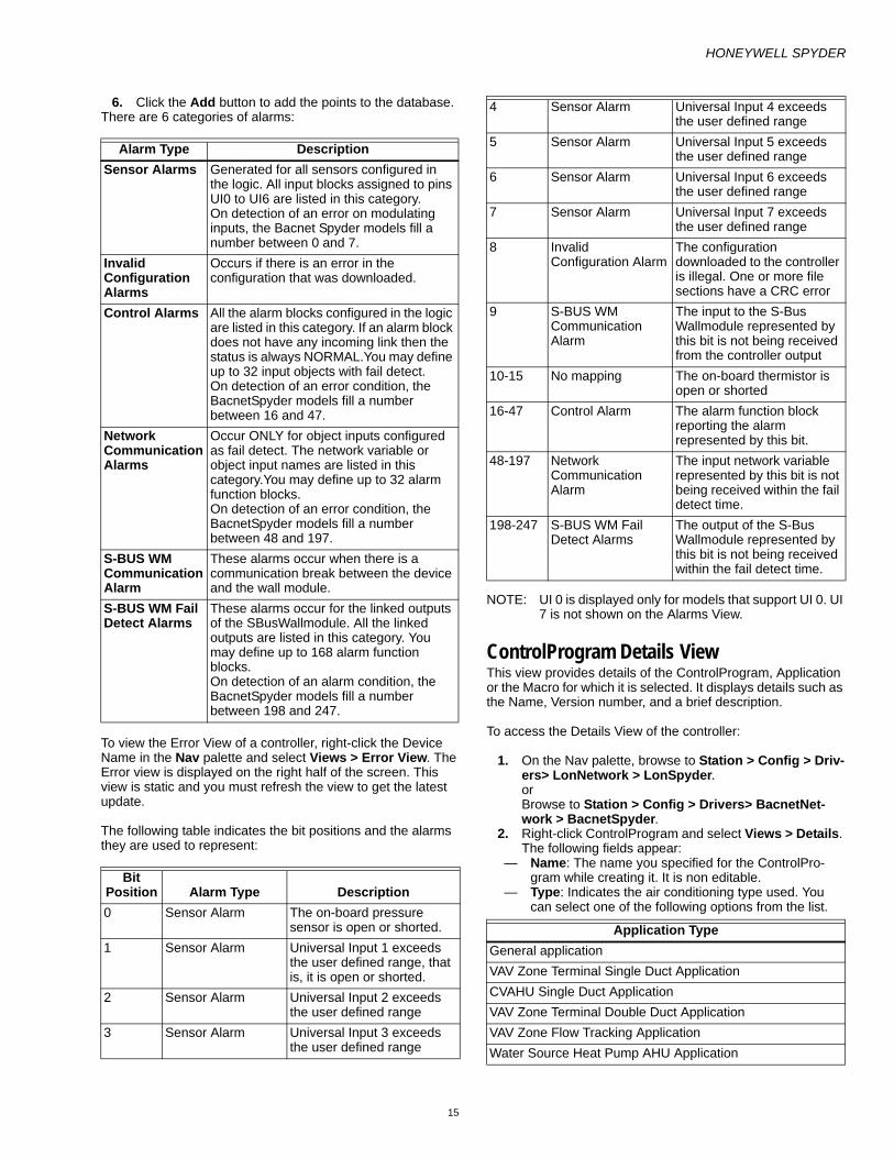
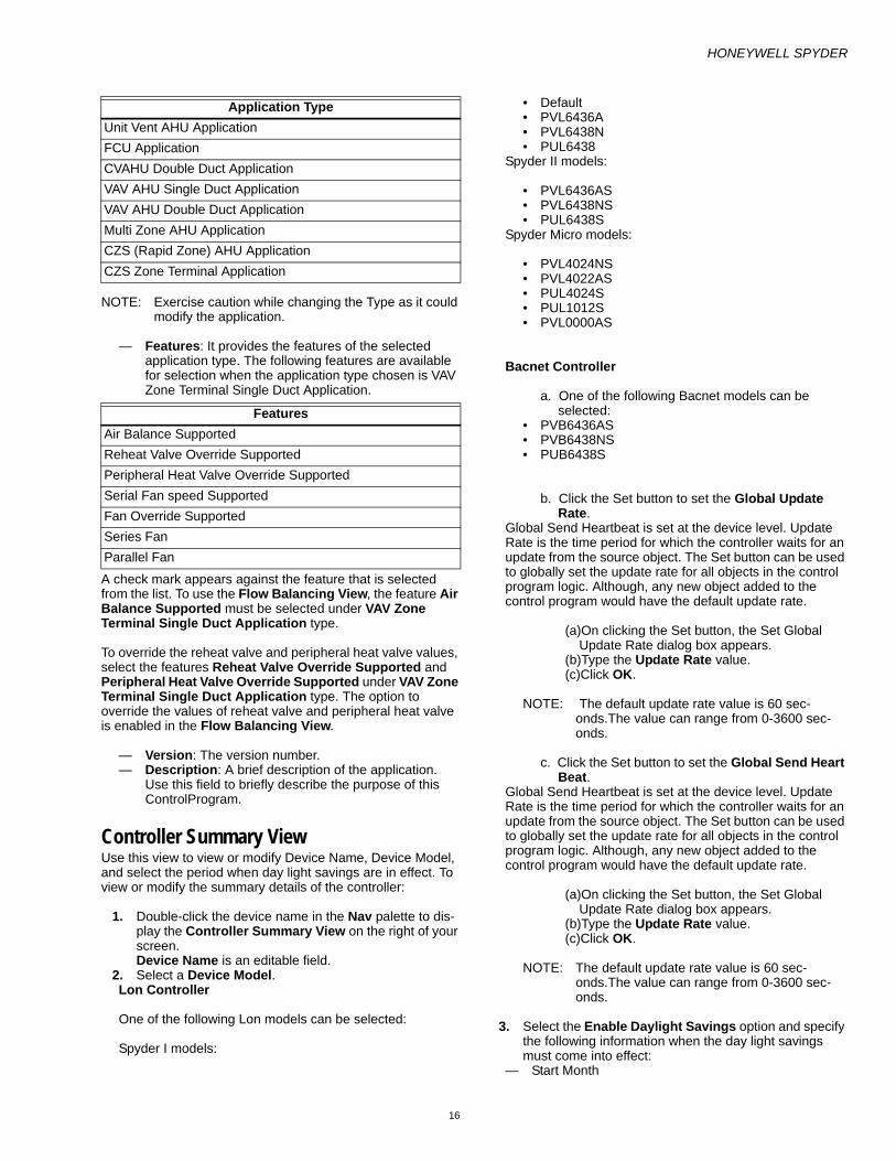
6. Click the Add button to add the points to the database.There are 6 categories of alarms:
To view the Error View of a controller, right-click the Device Name in the Nav palette and select Views > Error View. The Error view is displayed on the right half of the screen. This view is static and you must refresh the view to get the latest update.
The following table indicates the bit positions and the alarms they are used to represent:
NOTE: UI 0 is displayed only for models that support UI 0. UI 7 is not shown on the Alarms View.
ControlProgram Details ViewThis view provides details of the ControlProgram, Application or the Macro for which it is selected. It displays details such as the Name, Version number, and a brief description.
To access the Details View of the controller:
1. On the Nav palette, browse to Station > Config > Driv-ers> LonNetwork > LonSpyder. or Browse to Station > Config > Drivers> BacnetNet-work > BacnetSpyder.
2. Right-click ControlProgram and select Views > Details. The following fields appear:
— Name: The name you specified for the ControlPro-gram while creating it. It is non editable.
— Type: Indicates the air conditioning type used. You can select one of the following options from the list.
Alarm Type DescriptionSensor Alarms Generated for all sensors configured in
the logic. All input blocks assigned to pins UI0 to UI6 are listed in this category. On detection of an error on modulating inputs, the Bacnet Spyder models fill a number between 0 and 7.
Invalid Configuration Alarms
Occurs if there is an error in the configuration that was downloaded.
Control Alarms All the alarm blocks configured in the logic are listed in this category. If an alarm block does not have any incoming link then the status is always NORMAL.You may define up to 32 input objects with fail detect. On detection of an error condition, the BacnetSpyder models fill a number between 16 and 47.
Network Communication Alarms
Occur ONLY for object inputs configured as fail detect. The network variable or object input names are listed in this category.You may define up to 32 alarm function blocks.On detection of an error condition, the BacnetSpyder models fill a number between 48 and 197.
S-BUS WM Communication Alarm
These alarms occur when there is a communication break between the device and the wall module.
S-BUS WM Fail Detect Alarms
These alarms occur for the linked outputs of the SBusWallmodule. All the linked outputs are listed in this category. You may define up to 168 alarm function blocks. On detection of an alarm condition, the BacnetSpyder models fill a number between 198 and 247.
Bit Position Alarm Type Description0 Sensor Alarm The on-board pressure
sensor is open or shorted.1 Sensor Alarm Universal Input 1 exceeds
the user defined range, that is, it is open or shorted.
2 Sensor Alarm Universal Input 2 exceeds the user defined range
3 Sensor Alarm Universal Input 3 exceeds the user defined range
4 Sensor Alarm Universal Input 4 exceeds the user defined range
5 Sensor Alarm Universal Input 5 exceeds the user defined range
6 Sensor Alarm Universal Input 6 exceeds the user defined range
7 Sensor Alarm Universal Input 7 exceeds the user defined range
8 Invalid Configuration Alarm
The configuration downloaded to the controller is illegal. One or more file sections have a CRC error
9 S-BUS WM Communication Alarm
The input to the S-Bus Wallmodule represented by this bit is not being received from the controller output
10-15 No mapping The on-board thermistor is open or shorted
16-47 Control Alarm The alarm function block reporting the alarm represented by this bit.
48-197 Network Communication Alarm
The input network variable represented by this bit is not being received within the fail detect time.
198-247 S-BUS WM Fail Detect Alarms
The output of the S-Bus Wallmodule represented by this bit is not being received within the fail detect time.
Application TypeGeneral applicationVAV Zone Terminal Single Duct ApplicationCVAHU Single Duct ApplicationVAV Zone Terminal Double Duct ApplicationVAV Zone Flow Tracking ApplicationWater Source Heat Pump AHU Application
HONEYWELL SPYDER
16
NOTE: Exercise caution while changing the Type as it could modify the application.
— Features: It provides the features of the selected application type. The following features are available for selection when the application type chosen is VAV Zone Terminal Single Duct Application.
A check mark appears against the feature that is selected from the list. To use the Flow Balancing View, the feature Air Balance Supported must be selected under VAV Zone Terminal Single Duct Application type.
To override the reheat valve and peripheral heat valve values, select the features Reheat Valve Override Supported and Peripheral Heat Valve Override Supported under VAV Zone Terminal Single Duct Application type. The option to override the values of reheat valve and peripheral heat valve is enabled in the Flow Balancing View.
— Version: The version number. — Description: A brief description of the application.
Use this field to briefly describe the purpose of this ControlProgram.
Controller Summary ViewUse this view to view or modify Device Name, Device Model, and select the period when day light savings are in effect. To view or modify the summary details of the controller:
1. Double-click the device name in the Nav palette to dis-play the Controller Summary View on the right of your screen. Device Name is an editable field.
2. Select a Device Model. Lon Controller
One of the following Lon models can be selected:
Spyder I models:
• Default • PVL6436A • PVL6438N • PUL6438
Spyder II models:
• PVL6436AS • PVL6438NS • PUL6438S
Spyder Micro models:
• PVL4024NS • PVL4022AS • PUL4024S • PUL1012S • PVL0000AS
Bacnet Controller
a. One of the following Bacnet models can be selected:
• PVB6436AS • PVB6438NS • PUB6438S
b. Click the Set button to set the Global Update Rate.
Global Send Heartbeat is set at the device level. Update Rate is the time period for which the controller waits for an update from the source object. The Set button can be used to globally set the update rate for all objects in the control program logic. Although, any new object added to the control program would have the default update rate.
(a)On clicking the Set button, the Set Global Update Rate dialog box appears.
(b)Type the Update Rate value. (c)Click OK.
NOTE: The default update rate value is 60 sec-onds.The value can range from 0-3600 sec-onds.
c. Click the Set button to set the Global Send Heart Beat.
Global Send Heartbeat is set at the device level. Update Rate is the time period for which the controller waits for an update from the source object. The Set button can be used to globally set the update rate for all objects in the control program logic. Although, any new object added to the control program would have the default update rate.
(a)On clicking the Set button, the Set Global Update Rate dialog box appears.
(b)Type the Update Rate value. (c)Click OK.
NOTE: The default update rate value is 60 sec-onds.The value can range from 0-3600 sec-onds.
3. Select the Enable Daylight Savings option and specify the following information when the day light savings must come into effect:
— Start Month
Unit Vent AHU ApplicationFCU ApplicationCVAHU Double Duct ApplicationVAV AHU Single Duct ApplicationVAV AHU Double Duct ApplicationMulti Zone AHU ApplicationCZS (Rapid Zone) AHU ApplicationCZS Zone Terminal Application
Features Air Balance SupportedReheat Valve Override SupportedPeripheral Heat Valve Override SupportedSerial Fan speed SupportedFan Override SupportedSeries FanParallel Fan
Application Type

HONEYWELL SPYDER
17
— End Month — Start Day — End Day
NOTE: You must clear the Day Light Savings check box and download it to the controller, for the controller to stop using daylight savings.
4. Click Save to save the changes or Cancel to revert to the previous settings.
NOTE: You are free to select any device model even if the application created does not fit the memory require-ments of the target model. Honeywell Spyder per-forms necessary actions on model change and gives a report of the same.
NOTE: The LonSpyder I models do not support the SBus Wall module. On selecting any of these models, the Model Description indicates that the selected model does not support SBus wall module. The the Spyder II, and Spyder Micro models, and BacnetSpyder models support SBus wall module and the Model Description for these models indicates the same.
ControlProgram NV Configuration ViewA Network Variable (NV) is a data item such as a temperature, a switch value or actuator state. NVs can be thought of simply as point parameters. LonMark functional profiles define Standard Network Variable Types (SNVTs), but additional non-standard NVs are usually available, depending on the device, to store additional non-standard data.
There are three categories of NVs that the Lon Spyder supports. They are:
• Mandatory: Mandatory NVs are the default NVs mandatorily present in a Lon Spyder device.
• Fixed: You can use Fixed Dropable NVs while creating an application logic but can edit only its Internal Data Type. You can also display Fixed Dropable NVs on the wiresheet.
• Custom: Custom NVs are the NVs you create while creating an application logic. They can be created, edited, and deleted based on your requirements.
The Lon Spyder provides the following four built-in functions that enable you to connect function blocks with other function blocks.
• NVI - Network Variable Inputs • NVO - Network Variable Output • NCI - Network Configuration Input• Many to One NV - Many to One Network Variable The Lon Spyder provides built-in functions, Network Variable Inputs, to allow the selection of variables that are available from/to the network. The configured network variables are mapped to the Function Block memory space to be used by any Function Block. Each Network variable may be configured with a name.
Viewing the List of Network Variables1. Browse to Station > Config > Drivers > LonNetwork >
LonSpyder. 2. Select ControlProgram > Views > NV Configuration
View. The summary page appears with a list of pre-pro-grammed Mandatory, Fixed, and Custom NVs in a tabular format. The table has the following columns:
— NV Name: The name of the network variable.— Type: Indicates if the NV is of type NVI, NVO, NCI or
Many to One NV. — Category: Indicates if the NV is Mandatory, Fixed, or
Custom. — NV Container: Indicates where the NV is used.
3. You have options to: — Show on wiresheet as points - — Add NV — Edit NV — Delete NV
4. The bottom half of the NV Configuration view displays the software points available on the wiresheet in a tabu-lar format. The table has the following columns:
— Point Name: The name of the network point (Network Input/Network Setpoint/Network Output) as it appears on the wiresheet.
— Field Names: Indicates if the NV is of type NVI, NVO, NCI or Many to One NV.
— Point Container: Indicates where the software point is used. All software points that are used in a Program within an application are also listed.
5. You have options to: — Group as NV— Edit Point— Remove points from wiresheet
Group as NVYou can group points belonging to types NVI, NCI, NVO, Constants, and Invalid points to form a new NVI, NCI, or NVO.
NOTE: Use the CTRL key to select multiple points to group. This button is disabled in the following cases:
— If one or more selected points belong to a Fixed NV.— If one or more selected points belong to a Many to
One NV.— If one or more selected points is configured as Bit field.— If you select an input point and an output point.— If the point belongs to nciTempSetpoints
See the Add NVI, Add NCI, Add NVO, or Add Many to One NV topics for more details.
NOTE:
— Mandatory NVs cannot be used in the application logic. — Mandatory NVs cannot be edited or deleted.— In a Fixed NV, only Internal Data Type can be modified.— Custom NV is the user defined NV. A Custom NV can be
edited or deleted. — Fixed NVs marked as Fixed_Dropable can be exposed on
the wiresheet. Other fixed NVs cannot be exposed as points.
— Network Input with Point Type configured as Constant in a macro are not shown in the lower pane of the NV Configuration View.
— For each point that is copied and pasted on the wiresheet:

HONEYWELL SPYDER
18
— If the network type is a scalar SNVT, the new NV cre-ated is SNVT of the network type.
— If the network type is a Bit field, the new NV of SNVT type nearest to the selected internal data type is cre-ated automatically.
— In all other cases, a single-field UNVT with the same configuration as the point being copied is created.
Bacnet Object Configuration ViewAn Object is a data item such as a temperature, a switch value or actuator state. Objects can be thought of as point parameters.
The three categories of Objects supported by BacnetSpyder are:
• Mandatory: Mandatory Objects are the default Objects present compulsorily in a Bacnet Spyder device.
• Fixed: Fixed Dropable Objects can be used while creating an application logic and only its Internal Data Type can be edited. Fixed Dropable Objects can also be displayed on the wiresheet.
• Custom: Custom Objects are the objects that are created while creating an application logic. They can be created, edited, and deleted based on your requirements.
The Bacnet Spyder supports the following object types.
AVI - Analog Value Input
• AVO - Analog Value Output • AV Setpoint - Analog Value Setpoint • BVI - Binary Value Input • BVO - Binary Value Output • BV Setpoint - BinaryValue Setpoint • MVI - Multi-state Value Input • MVO - Multi-state Value Output • MV Setpoint - Multi-state Value Setpoint
The configured objects are mapped to the Function Block memory space to be used by any Function Block. Each Object is configured with a name.
Viewing the List of Bacnet Objects1. Browse to Station > Config > Drivers > BacnetNet-
work > BacnetSpyder. 2. Select ControlProgram > Views > Object Configuration
View. The summary page appears with a list of pre-pro-grammed Mandatory, Fixed, and Custom Objects in a tabular format. The table has the following columns:
— Name: The name of the object.— Type: Indicates if the object is of type AVI, AVO, AV
Setpoint, BVI, BVO, BV Setpoint, MVI, MVO, or MV Setpoint.
— Category: Indicates if the Object is Mandatory, Fixed, or Custom.
— Object Container: Indicates where the Object is used.— Object Instance: A unique number that is automati-
cally assigned to the object.— Update Rate: The rate at which inputs are sent to the
network.— Send Heartbeat: The rate at which inputs are
received from the network.
3. You have options to: — Show on wiresheet as points— Add NV — Edit NV — Delete NV
4. The bottom half of the Object Configuration view dis-plays the physical and software points available on the wiresheet in a tabular format. The table has the follow-ing columns:
— Point Name: The name of the physical /software point as it appears on the wiresheet.
— Field Names: Indicates the Object type. — Point Container: Indicates where the physical /soft-
ware point is used. All physical /software points that are used in a Program within an application are also listed.
5. You have options to: — Create Bacnet Object from Point: Use this button to
convert an invalid point into a valid Bacnet object.— Edit Point: Select a point and click this button to edit
its configuration.— Remove points from wiresheet: Use this button to
remove a point from the wiresheet.
NOTE:
— Mandatory Objects cannot be used in the application logic. — Mandatory Objects cannot be edited or deleted.— In a Fixed Dropable Object, only Internal Data Type can be
modified.— Custom Object is the user defined Object. A Custom
Object can be edited or deleted. — Fixed Objects marked as Fixed_Dropable can be exposed
on the wiresheet. Other fixed objects cannot be exposed as points.
— Network Input with Point Type configured as Constant in a macro are not shown in the lower pane of the Object Configuration View.
ControlProgram Wiresheet ViewThe Wiresheet View is that screen or view of the Honeywell SpyderTool interface that you use to engineer the tool. Function blocks, Physical points, and NVs or Objects are the building blocks of the logic you can create and download to the Honeywell Spyder controller.
You can create and build your own logic using function blocks or create ControlProgram and libraries or macros, using the Wiresheet view. On this view, you can drag the function blocks, Physical points, and NVs or Objects that you use to build and define logic. This logic then forms a part of the macros and Spyder libraries that you want to save and reuse.
NOTE: Names of Physical points must be unique. No two Physical points can have the same name.
To view the Wiresheet View of the Lon controller:
1. On the Nav palette, browse to Station > Config > Driv-ers > LonNetwork > LonSpyder.
2. Expand LonSpyder and select ControlProgram. 3. Right-click ControlProgram and select Views >
Wiresheet. To view the Wiresheet View of the Bacnet controller:

HONEYWELL SPYDER
19
1. On the Nav palette, browse to Station > Config > Driv-ers > BacnetNetwork > BacnetSpyder.
2. Expand BacnetSpyder and select ControlProgram. 3. Right-click ControlProgram and select Views >
Wiresheet.
The wiresheet is displayed on the right of the screen in the Engineering mode. The Wiresheet View consists of a wiresheet like appearance on the right pane. You can drag the function blocks, Physical points, and NVs or Objects on to this wiresheet and make the connections to and from Physical points and function blocks to build your logic on the wiresheet. It also consists of fixed Physical points. It also consists of a snapshot view of the entire wiresheet page on the top right corner. This helps you to have an overview of the entire sheet in cases where you have many function blocks/Physical points and so on.
NOTE: All the Fixed Physical points are visible on the Con-trolProgram Wiresheet view of the Controller.
Designing The Application LogicNOTE: You can use the Windows mechanism of copy/paste/
cut to copy/delete Function blocks, NVs, and IOs on the wiresheet
To design your application:
1. Decide the Physical points 2. Develop Sequence 3. Decide the interface requirements for the open Lon con-
nection or with other Lon devices 4. Develop software logic using modules or import the
modules that you want to use 5. Interconnect Physical points to other modules and to the
outside connections 6. Test the logic through simulation 7. Correct any changes to the design or modifications to
the Macros 8. Save Macros that you would want to reuse in a library 9. Save your device in a library if you want to be able to
reuse it here or on other projects.
NOTE: If an application logic configured using a function block with the Ignore Invalid Input property is dropped on to the wiresheet of a controller with any of these LonSpyder I models - PVL6436A, PVL6438N, or PUL6438, a warning message appears.
ControlProgram Resource Usage ViewThe ControlProgram, Spyder libraries and macros you create consume memory. The function blocks, Physical points and NVs or Objects have different memory usage. Some elements of a function block may use a Float RAM while some others could be using memory in the Non-Volatile RAM.
The Resource Usage View provides details of the total memory and the used memory as a result of all the ControlProgram, Spyder libraries and macros you create.
You can see the memory usage at different levels as described:
• ControlProgram Resource Usage • Application Resource Usage • Macro Resource Usage • Spyder library Resource Usage
NOTE: At each of these levels the memory used up by the entire application is shown.
ControlProgram Resource UsageTo view the Resource Usage View of the controller:
1. On the Nav palette, browse to Station > Config > Driv-ers > LonNetwork > LonSpyder. or Browse to Station > Config > Drivers > BacnetNet-work > BacnetSpyder.
2. Right-click LonSpyder or BacnetSpyder. or Expand LonSpyder or BacnetSpyder and select Con-trolProgram. Right-click ControlProgram.
3. Select Views > Resource Usage. The Controller Details appear on the right half of the screen.
4. You can select the controller Device Model. This is the model number or make of the controller that you are programming using this tool.
5. The Memory Usage chart graphically displays a bar chart of the total memory and used memory details. You can click the Tabular View button to view the breakup of RAM pool usage in a tabular format. Click the Tabular View button to hide/display the tabular view.
NOTE: The upper limit range of total memory for Float RAM, Byte RAM, Flash, Non Volatile RAM, and RAM pool is higher in case of Spyder Micro controllers.
6. The Blocks Usage table displays the number of Func-tion blocks, Network variables or Objects, and Physical IOs used at the device level. Physical IOs indicate the number of hardware pins used.
NOTE: The number of blocks supported by LonSpyder Micro is higher. They support 200 Function blocks, 220 Network Variables, and 21 Physical IOs.
7. Click the Memory usage details button to view details of the different memory types. The Block Memory Details tab displays memory usage details of the Func-tion blocks, NVs or Objects, and Physical IOs used in the device in a tabular format.
Name DefinitionBlock Name of the Function block, IO, or NV.Type Indicates the type of the Function block, IO, or
NV.Float RAM Indicates the Float RAM usage of the Function
block, IO, or NV.Byte RAM Indicates the Byte RAM usage of the Function
block, IO, or NV.

HONEYWELL SPYDER
20
1. Click the RAM Pool Usage Details tab to view the memory usage status of the controller. You can click the Tabular View button to view the breakup of RAM pool usage details in a tabular format. Click the Tabular View button to hide/display the tabular view.
2. Click the Validate button to find out the Error messages and Warning messages, if any, in a new window. Typi-cally you will find messages pertaining to warnings, errors and detailed report of invalid points, IOs, excess memory counters, excess NVs created, excess engi-neering units configured and so on. Click OK to close the window.
3. Click Save if you have made any changes to the Con-troller Model for the changes to take effects.
ControlProgram Terminal Assignment ViewThis view provides a layout of the physical arrangement of the pins on the controller. Use this view to view or modify the configuration of inputs or outputs of the selected controller. According to the selected controller model, you can select which inputs or outputs must be assigned to the pins. The IO pins for Spyder I, Spyder II, and Spyder Bacnet models are:
• Universal Inputs (UI) 1 to 6 • Digital Inputs (DI) 1 to 4 • Analog Outputs (AO) 1 to 3 • Digital Outputs (DO) 1 to 8
The inputs or outputs you have used to build the application logic along with invalid IO points are available as options for UI, DI, AO, and DO. You can choose the inputs or outputs that are used to build the application logic, to be assigned to the physical pins of the controller. You can choose invalid IOs and reassign them to valid terminals.
NOTE: UI 0 and UI 7 for Spyder I, Spyder II, and Spyder Bacnet models are not shown on the Terminal Assignment View.
Example:
Let us say you have used four Modulating Inputs named Modulating Input 1, Modulating Input 2, Modulating Input 3, Modulating Input 4 and two Binary Inputs named BinaryInput 1 and BinaryInput2. On the Terminal Assignment View, for each Universal Input (UI 0 to 7), you have the option to choose Modulating Inputs 1 to 4 or Binary Inputs 1 to 2.
The IO pins for Spyder Micro models are:
• Universal Inputs (UI) 1 to 4 • Analog Outputs (AO) 1 and 2 • Digital Outputs (DO) 1 to 4
The input pin UI1 is fixed for Pulse_Meter or Counter type sensors, or Momentary type binary input. If the pin is not available or is currently assigned to another point, the tool creates the point as an invalid point.
To view the Terminal Assignment View of the controller:
1. On the Nav palette, browse to Station > Config > Driv-ers > LonNetwork > LonSpyder. or Browse to Station > Config > Drivers > BacnetNet-work > BacnetSpyder.
2. Right-click LonSpyder or BacnetSpyder. or Expand LonSpyder or BacnetSpyder and select Con-trolProgram. Right-click ControlProgram.
3. Select Views > Terminal Assignment View. The view appear on the right side of the screen.
4. Assign all the inputs and outputs and click Save to save the details or Reset to revert to the last saved changes.
NOTE: If you change the device model , the physical IOs continue to retain the IO pins previously assigned except in the following scenarios:
1. If a custom IO has been assigned a pin that is fixed in the target model, HoneywellSpyder assigns a free pin, if available. If no free pin is available, the IO becomes an invalid IO.
2. If there was a fixed pin assigned to a fixed IO in the source model and is different in the target model, Honeywell Spyder reassigns the fixed pin in the target model to that IO. But if the fixed pin is already in use in the target model, Honeywell Spyder converts the IO to the nearest custom type and reassigns a valid pin available. If there is no valid pin available the IO becomes unas-signed.
3. If the target model supports less number of IOs than the source model, Honeywell Spyder unas-signs the pins for the IOs that are in excess in the target model.
4. If target model supports more number of IOs than the source, Honeywell Spyder assigns available free pins to any invalid IOs present.
NOTE: The UI0 pin is not displayed on the Terminal Assign-ment View.
A report of all actions taken is generated.
If the name of a custom NV or Object clashes with a fixed NV or Object name in the target model, Honeywell Spyder generates a new unique name for the custom NV or Object and creates the new fixed NV or Object.
Macro Details ViewThis view provides details of the Macro. It displays details such as the Name, Type, Version number, and a brief description.
To access the Details View of the macro:
Flash Indicates the Flash memory usage of the Function block, IO, or NV.
NV RAM Indicates the NV RAM usage of the Function block, IO, or NV.
Valid Indicates if the point is valid/inavlid.Block Container
Indicates the location of the Function block, IO, or NV.

HONEYWELL SPYDER
21
1. On the Nav palette, browse to Station > Config > Driv-ers > LonNetwork > LonSpyder. or Browse to Station > Config > Drivers > BacnetNet-work > BacnetSpyder.
2. Expand ControlProgram and right-click Macro. 3. Select Views > Details. The following fields appear: — Name: The name you specified for the Program while
creating it. It is non editable. — Type: The type of Program. It is non editable. — Version: The version number. It is non editable. — Description: A brief description of the macro. Use this
field to briefly describe the purpose of this macro.
Macro Resource Usage ViewThe ControlProgram, Spyder libraries and macros you create consume memory. The function blocks, Physical points, and NVs or Objects have different memory usage. Some elements of a function block may use a Float RAM while some others could be using Non-Volatile RAM.
The Resource Usage View provides details of the total memory and the used memory as a result of all the logic you have used in creating the macro.
To view the Resource Usage View of the macro:
1. On the Nav palette, right-click the Macro and select Views > Resource Usage. The Resource Usage View is displayed on the right of the screen.
2. The Memory Usage chart graphically displays a bar chart of the total memory and used memory details.
3. The memory usage details of the different memory types is also displayed in a tabular format.
Macro Wiresheet ViewTo view the Macro wiresheet:
1. On the Palette palette, expand Util to view the list of utility functions.
2. Right-click Macro and select Views > Wiresheet. The Wiresheet is displayed on the right of the screen. Use this screen to build your logic using Physical points and Function Blocks.
Application Details ViewThis view provides details of the Application. It displays details such as the Name, Type, Version number, and a brief description.
To access the Details View of the Application:
1. On the Nav palette, browse to Station > Config > Driv-ers > LonNetwork > LonSpyder. or Browse to Station > Config > Drivers > BacnetNet-work > BacnetSpyder.
2. Expand ControlProgram and right-click Application. 3. Select Views > Details. The following fields appear: — Name: The name you specified for the Program while
creating it. It is non editable. — Type: Indicates the type used. It is non-editable. — Version: The version number. It is non editable.
— Description: A brief description of the application. Use this field to briefly describe the purpose of this Program.
Application Programming ViewThe Wiresheet View for the Sub Application that screen/view of the Honeywell SpyderTool interface that you use to engineer the tool. You can create the Program by connecting function blocks to network inputs/setpoints/outputs and physical inputs/outputs.
To view the Application Wiresheet view of the controller:
1. On the Nav palette, browse to Station > Config > Driv-ers > LonNetwork > LonSpyder. or Browse to Station > Config > Drivers > BacnetNet-work > BacnetSpyder.
2. Expand LonSpyder or BacnetSpyder and select Con-trolProgram.
3. Expand the ControlProgram and right-click the Appli-cation whose wiresheet you want to view and select Views > Wiresheet. The wiresheet is displayed on the right of the screen.
4. Use this screen to build your Program using Physical points and Function Blocks.
NOTE:
— If you drag an Application from the Nav palette on to the Wiresheet of an ControlProgram, Physical points are not visible.
— If you drag an Application from a library to the Control-Program’s Wiresheet View, Physical points are visible in the wiresheet of the Program and not on the Control Program Wiresheet View of the parent.
— If you delete the Program, fixed Physical points appear in the Wiresheet View of the ControlProgram.
Application Resource Usage ViewThe application logic, Spyder libraries and macros you create consume memory. The function blocks, Physical points and NVs / Objects have different memory usage. Some elements of a function block may use a Float RAM while some others could be using Non-Volatile RAM.
The Resource Usage View provides details of the total memory and the used memory as a result of all the application logic, Spyder libraries and macros you have used in creating the Program.
To view the Resource Usage View of the Program:
1. On the Nav palette, browse to Station > Config > Driv-ers > LonNetwork > LonSpyder. or Browse to Station > Config > Drivers > BacnetNet-work > BacnetSpyder.
2. Expand LonSpyder or BacnetSpyder and expand ControlProgram.
3. Right-click ControlProgram and select Views > Resource Usage. The Resource Details appear on the right half of the screen.

HONEYWELL SPYDER
22
4. The Controller Model is non editable. This is model number or make of the controller that you are program-ming using this tool.
5. The Memory Usage chart graphically displays a bar chart of the total memory and used memory details.
6. The memory usage details of the different memory types is also displayed in a tabular format.
Application NV Configuration ViewNOTE: This screen displays only those NVs that are used in
this Application.
A Network Variable (NV) is a data item such as a temperature, a switch value or actuator state. NVs can be thought of simply as point parameters. LonMark functional profiles define Standard Network Variable Types (SNVTs), but additional non-standard NVs are usually available, depending on the device, to store additional non-standard data.
There are three categories of NVs that the Lon Spyder supports. They are:
• Mandatory: Mandatory NVs are the default NVs mandatorily present in a Lon Spyder device.
• Fixed: You can use Fixed Dropable NVs while creating an application logic but can edit only its Internal Data Type. You can also display Fixed Dropable NVs on the wiresheet.
• Custom: Custom NVs are the NVs you create while creating an application logic. They can be created, edited, and deleted based on your requirements.
The Honeywell Spyder Tool provides the following four built-in functions that enable you to connect function blocks with other function blocks.
• NVI: Network Variable Inputs • NVO: Network Variable Output • NCI: Network Configuration Input• Many to One NV: Many to One Network Variable The Honeywell Spyder Tool provides built-in functions, Network Variable Inputs, to allow the selection of variables that are available from/to the network. The configured network variables are mapped to the Function Block memory space to be used by any Function Block. Each Network variable may be configured with a name.
Viewing the List of Network Variables1. Browse to Station > Config > Drivers > LonNetwork >
LonSpyder. 2. Expand ControlProgram and right click Application
and select Views > NV Configuration View. The sum-mary page appears with a list of NVs used in the Pro-gram appears. The table has the following columns:
— NV Name: The name of the network variable.— Type: Indicates if the NV is of type NVI, NVO, NCI or
Many to One NV. — Category: Indicates if the NV is Mandatory, Fixed, or
Custom. — Display on WireSheet: Indicates if the NV will be dis-
played on the wiresheet or not.3. You have options to:— Show on wiresheet as points — Add NV— Edit NV— Delete NV
4. The bottom half of the NV Configuration view displays the software points available on the wiresheet in a tabu-lar format.
The table has the following columns:
• Point Name: The name of the software point (Network Input/Network Setpoints/NetworkOutput) as it appears on the wiresheet.
• Field Names: Indicates if the NV is of type NVI, NVO, NCI or Many to One NV.
• Point Container: Indicates where the software point is used.
NOTE:
— Mandatory NVs cannot be used in the application logic.
— Mandatory NVs cannot be edited or deleted.— In a Fixed NV, only Internal Data Type can be
modified.— Custom NV is the user defined NV. A Custom NV
can be edited or deleted. — Fixed NVs marked as Fixed_Dropable can be
exposed on the wiresheet. Other fixed NVs can-not be exposed as points.
— For each point that is copied and pasted on the wiresheet, a new NV of SNVT type nearest to the selected datatype is created automatically.
Application Bacnet Object Configuration ViewNOTE: This screen displays only those Bacnet Objects that
are used in this Application.
An Object is a data item such as a temperature, a switch value or actuator state. Objects can be thought of as point parameters.
There are three categories of Objects that the BacnetSpyder supports. They are:
• Mandatory: Mandatory Objects are the default Objects present compulsorily in a Bacnet Spyder device.
• Fixed: Fixed Dropable Objects can be used while creating an application logic and only its Internal Data Type can be edited. Fixed Dropable Objects can also be displayed on the wiresheet.
• Custom: Custom Objects are the objects that are created while creating an application logic. They can be created, edited, and deleted based on your requirements.
The Bacnet Spyder supports the following object types.
• AVI - Analog Value Input • AVO - Analog Value Output • AV Setpoint - Analog Value Setpoint • BVI - Binary Value Input • BVO - Binary Value Output • BV Setpoint - BinaryValue Setpoint • MVI - Multi-state Value Input • MVO - Multi-state Value Output • MV Setpoint - Multi-state Value Setpoint The configured objects are mapped to the Function Block memory space to be used by any Function Block. Each Object is configured with a name.

HONEYWELL SPYDER
23
Viewing the List of Bacnet Objects1. Browse to Station > Config > Drivers > BacnetNet-
work > BacnetSpyder.2. Expand ControlProgram and right-click Application
and select Views > Object Configuration View. The summary page appears with a list of Objects used in the Program.
The table has the following columns:
• Name: The name of the object. • Type: Indicates if the object is of type AVI, AVO, AV
Setpoint, BVI, BVO, BV Setpoint, MVI, MVO, or MV Setpoint.
• Category: Indicates if the Object is Mandatory, Fixed, or Custom.
• Object Container: Indicates the location of the Object. • Object Instance: A unique number that is automatically
assigned to the object. • Update Rate: The rate at which inputs are sent to the
network. • Send Heartbeat: The rate at which inputs are received
from the network. 3. You have options to: — Show on wiresheet as points — Add NV — Edit NV— Delete NV
4. The bottom half of the Object Configuration view dis-plays the software points available on the wiresheet in a tabular format.
The table has the following columns:
• Point Name: The name of the physical /software point as it appears on the wiresheet.
• Field Names: Indicates the Object type. • Point Container: Indicates where the physical /software
point is used. All physical /software points that are used in a Program within an application are also listed.
NOTE:
— Mandatory Objects cannot be used in the application logic.
— Mandatory Objects cannot be edited or deleted.— In a Fixed Dropable Objects, only Internal Data Type
can be modified.— Custom Object is the user defined Object. A Custom
Object can be edited or deleted.— Fixed Objects marked as Fixed_Dropable can be
exposed on the wiresheet. Other fixed objects cannot be exposed as points.
Actions on BacnetSpyder explained
DownloadPerform this action to download the logic to the ControlProgram of an online device. If there is no modification done to the logic from previous download to that controller apart from Setpoints value changes, Schedule block configuration changes, Wall module block configuration changes, Day Light Savings changes, tool performs a quick download of the configuration.
Spyder UploadPerform this action to upload application in the controller to the ControlProgram. If the application in the online controller matches with application in Control Program, invoking this Action does only a quick upload. In the case of quick upload, tool only uploads Network Setpoint values, Schedule, Wall Module, Day Light Savings configurations. If the Control Program application is different than that in the device, tool perform a full upload.
Write Device InstancePerform this action to change the device instance number in the online device through Niagara. Change the device Instance number in Device Object under Config object of a device and click Action to write the changed value to the controller.
Generate Network ObjectsThe Generate Network Objects action on device level creates the object references from control program to create the binding between the objects. These Object references are listed and used in Add Bindings dialog to make the binding between the devices.
The Input points object references are displayed in the Target details of Add Bindings dialog box.
The Output points object references are displayed on the Source details of Add Bindings dialog box.
The Binary Output and Modulating Output points have 16 priority input object references and an output object reference on device level. The priority object references are displayed in Target details and output object reference are displayed in Source details of Add Binding dialog box.
On restarting the station the object references are removed from the device if it is not involved in binding.
Clear slotsThe object references for binding are created using the Generate network objects action on the device level (refer Generate network Objects action description).
The Clear slots action is used to remove the object references that are not involved in binding.
Clear BindingsThe Clear Bindings action on device level removes the binding information from the controller.
The clear binding action changes the bound links to new Links. If the device is having the obsolete Links then the obsolete links are removed from the controller. These can be observed in Bacnet Link manager view (see Types of Link Status section for more information).
The clear binding action can be performed only in the following conditions:
• Device should be online.• Device should be in the downloaded state.• Device should not be in use

HONEYWELL SPYDER
24
Learn LinksThe Learn Links action on device level learns the bound links from the device.
When the bound link is deleted from the link manger view then the link are displayed as obsolete link. If the user wants to restore the bound link then the user can perform the learn links action on the device. After learn Links the obsolete link are changed to bound link.
The Learn Links action can be performed only in the following conditions:
• Device should be online.
• Device should be in the downloaded state.• Device should not be in use.
Fetch Object Names The Learn Links action first checks if the device from which the link is learnt is having the object reference at the device level, if its not present it will look for the object in the control program. But for the other device involved in binding it only checks for the object reference at the device level and if the reference is not found it would create default object references. In this case the Fetch Object Names action loads the control program and fetch the exact name of the object and rename the default name.

HONEYWELL SPYDER
25
PHYSICAL POINTSPhysical points are logical objects that are used in building application logic. Depending on the model selected, default (Fixed) Physical points, for that model, are made available.
Example: For the LonSpyder I model PVL6436A, you can configure Actuator and On Board Pressure Sensor as fixed physical points.For the LonSpyder I model PVL 6438N, you can only configure On Board Pressure Sensor as a fixed physical point.
The Honeywell SpyderTool automatically validates rules, based on the model selected.
The four types of Physical points available that you can configure are:
• Binary Inputs • Binary Outputs • Modulating Inputs • Modulating Outputs
Binary InputsA binary input is a physical input. You can configure Binary Input blocks and use them while creating application logic.
NOTE: A binary input cannot be dropped under a macro
To add and configure a binary input block.
1. Right-click ControlProgram under Honeywell Spyder in the Nav palette and select Views > Wiresheet View to view the wiresheet.
2. Drag the Binary Input block from the Spyder Palette on to the wire sheet.
3. Type the desired name for the Binary Input block and click OK. The block appears as a container on the wire sheet similar to any function block.
4. Right-click the container and select Configure Proper-ties. The Configure Properties dialog box appears. The following table defines the fields shown in the dia-log box..
While using a LonSpyder Controller, the following fields are displayed.
NOTE:
— If the Input Type is Momentary for a Binary Input and if the UI1 pin is not available, or is assigned another point, then the tool creates the point as an invalid point.
— For a Momentary type binary input, when there is an OPEN to CLOSE to OPEN transition on the physical input, the input state changes from FALSE to TRUE (or) TRUE to FALSE.
— The Momentary type binary input can be configured to be Normally Open or Normally Close. This reverses the TRUE/FALSE logic.
While using a Bacnet Controller, the following fields are displayed.
Name DefinitionPoint Name
Type a name of the function block or use the default names given by the tool.
Point Type
Binary Input is the default selection. You can select Constant, Network Input, Network Setpoint, Binary Input or Modulating Input to change the point type.
Input Type
When the input type is selected as Momentary this input can be assigned only to the UI1 pin in Spyder Micro models: PVL4024NS, PVL4022AS, PUL4024S, PUL1012S, and PVL0000AS. In other Spyder models if Momentary is selected as input type , then the point will be an invalid point. When Maintained is selected this pin can be assigned to any input pin.
Input State
Normally OpenNormally Closed
OK Saves the entered information and closes the dialog box.
Cancel Closes the dialog box. Any information entered is lost.
Name DefinitionPoint Name Type a name of the function block or use the
default names given by the tool. Point Type Binary Input is the default selection. You
can select Constant, Binary Input, Modulating Input, Network Input or Network Setpoint to change the point type.
Input Type When the input type is selected as Momentary this input can be assigned only to the UI1 pin in Spyder Micro models: PVL4024NS, PVL4022AS, PUL4024S, PUL1012S, and PVL0000AS. In other Spyder models if Momentary is selected as input type , then the point will be an invalid point. When Maintained is selected this pin can be assigned to any input pin.

HONEYWELL SPYDER
26
The following table defines the fields shown in the Advanced screen of a Binary Input point..
NOTE:
— If the Input Type is Momentary for a Binary Input and if the UI1 pin is not available, or is assigned another point, then the tool creates the point as an invalid point.
— You can drag IOs on to the wiresheet even when all pins are used up. Honeywell Spyder allows IOs to be dropped but they are not assigned with a pin. Such IOs are termed as invalid IOs. A message indicating that the IO does not get a pin is displayed.
— When a physical IO (Modulating input, Binary input, Modulating output, Binary output) with a valid IO pin is copied and pasted in the wiresheet, the resulting IO gets the same configuration as the source and a new available pin. If no free pin is available, the resulting IO becomes an invalid IO.
— When an invalid physical IO (Modulating input, Binary input, Modulating output, Binary output) is copied and pasted in the wiresheet, the resulting IO gets the same configuration as the source and it is also an invalid IO.
Input State Normally OpenNormally Closed
Advanced Displays the Bacnet object details. Object Name, Object Type, Object Instance are the fields provided. Object Name is automatically provided by the tool and can be edited. Object Instance number can also be edited. Object Type is a read only field and cannot be edited. If the GPU option in the advanced dialog box is set to True, Send Heartbeat is enabled.
OK Saves the entered information and closes the dialog box.
Cancel Closes the dialog box. Any information entered is lost.
Name DescriptionObject Name Displays the name of the binary
input point. The object name can be edited.
Field Name Displays the name of the backend object created for the input point. It is non-editable.
Object Type Displays the object type as Binary Input. It is non-editable.
Object Instance A unique number that is automatically assigned to the object. This field is editable. If you try replacing the instance value with a value of your choice, the replacement is successful only if the value of your choice is not in use by any other object.
Update Interval The rate at which the input point is updated.
GPU Set the GPU of each binary input to either True or False.• True means if the Binary Input is
bound and it has not sent an update to the Bacnet network target in the GPU specified time then an alarm is generated and the Binary Input is set to Invalid.
• False means the Binary Input retains what was written to it until a Bacnet network source changes it or the Honeywell Spyder has a power outage or resets.
Send Heart Beat The rate at which input points send data to the network.
Name Definition

HONEYWELL SPYDER
27
Point Conversion
Binary OutputsA binary output is a physical output. You can configure Binary Output blocks and use them while creating application logic.
To add and configure a binary output block:
1. Right-click ControlProgram under LonSpyder or Bac-netSpyder in the Nav palette and select Views > Wiresheet View to view the wiresheet.
2. Drag the Binary Output block from the Spyder Palette on to the wire sheet.
3. Type the desired name for the Binary Output block and click OK. The block appears as a container on the wire sheet similar to any function block.
4. Right-click the container and select Configure Proper-ties. The Binary Output dialog box appears. The fol-lowing table defines the fields shown in the dialog box.
What do I convert To what do I
convert? How do I do it? What is the effect?Binary Input Constant 1. Right-click the Binary
input block and select Configure Properties.
2. Select Constant from the Point Type list.
3. Click OK..
1. If the Binary Input was connected to a slot of a function block, the slot is converted from Connector type to Constant.
2. Any IO pins used by the Binary input are freed.
Binary Input NCI 1. Right-click the Binary input block and select Configure Properties.
2. Select Constant from the Point Type list.
3. Enter a Value.4. Select Share Point on
Network.5. Click OK.
1. The IO pins used by the Binary Input are freed.
2. A new NCI of type Snvt is created, deter-mined by the Point Category, Internal Data Type unit selected.
3. The new NCI is seen in the NVs table in the NV Configuration View.
Binary Input Network Input (NVI)
1. Right-click the Binary input block and select Configure Properties.
2. Select Constant from the Point Type list.
3. Enter a Value.4. Select Share Point on
Network.5. Click OK.
1. The IO pins used by the Binary Input are freed.
2. A new NVI of type Snvt is created, deter-mined by the Point Category, Internal Data Type unit selected.
3. The new NVI is seen in the NVs table in the NV Configuration View.
Binary Input Modulating Input
1. Right-click the Binary input block and select Configure Properties.
2. Select Modulating Input from the Point Type list.
3. Select Type.4. Select Data Type.5. Click OK..
1. If there are no IO pins available for the target physical IO (in this case, the Modulating input that is created), the point becomes an invalid IO.
2. A warning message appears indicating that there are no more pins to allocate, and an unassigned IO is created.
Binary Input Network Setpoint
1. Right-click the Binary input block and select Configure Properties.
2. Select Network Set-point from the Point Type list.
3. Select Type. 4. Click OK.
1. The IO pins used by the Binary Input are freed.
2. The new setpoint input is seen in the Objects table in the Object Configuration View.
Binary Input Network Input 1. Right-click the Binary input block and select Configure Properties.
2. Select Network Input from the Point Type list.
3. Select Type. 4. Click OK.
1. The IO pins used by the Binary Input are freed.
2. The new network input is seen in the Objects table in the Object Configuration View.

HONEYWELL SPYDER
28
While using a LonSpyder Controller, the following fields are displayed.
While using a Bacnet Controller, the following fields are displayed.
The following table defines the fields shown in the Advanced screen of a Binary Output point.
NOTE:
— You can drag the IOs on to the wiresheet even when all pins are used up. Honeywell Spyder allows IOs to be dropped but they are not assigned with a pin. Such IOs are termed as invalid IOs. A message indicating that the IO does not get a pin is displayed.
— When a binary output is deleted, if it had a valid IO pin assigned, the freed pin is automatically assigned to an invalid Modulating output config-ured as PWM type or to an invalid binary output, if any.
— When a physical IO (Modulating input, Binary input, Modulating output, Binary output) with a valid IO pin is copied and pasted in the wiresheet, the resulting IO gets the same configuration as
Name DefinitionPoint Name
Type a name or use the default names given by the tool.
Point Type Binary Output is the default selection. You can select Software Output, Binary Output or Modulating Output to change the point type.
OK Saves the entered information and closes the dialog box.
Cancel Closes the dialog box. Any information entered is lost.
Name DefinitionPoint Name Type a name or use the default
names given by the tool. Point Type Binary Output is the default
selection. You can select Network Output, Binary Output or Modulating Output to change the point type.
Advanced Displays the Bacnet object details. Object Name, Object Type, Object Instance are the fields provided. Object Name is automatically provided by the tool and can be edited. Object Instance number can also be edited. Object Type is a read only field and cannot be edited. If the GPU option in the advanced dialog box is set to True, Send Heartbeat is enabled.
OK Saves the entered information and closes the dialog box.
Cancel Closes the dialog box. Any information entered is lost.
Name DescriptionObject Name Displays the name of the binary
output point. The object name can be edited.
Field Name Displays the name of the backend object created for the output point. It is non-editable.
Object Type Displays the object type as Binary Output. It is non-editable.
Object Instance A unique number that is automatically assigned to the object. This field is editable. If you try replacing the instance value with a value of your choice, the replacement is successful only if the value of your choice is not in use by any other object.
Relinquish Default A default value can be set for the Binary Output when all the priority slots in the Priority Override function block are set to null.
Logic Command Priority
Enables you to assign a priority to the output point. The point is mapped to the priority level in the Priority Override function block.
Update Interval The rate at which the output point is updated.
GPU Set the GPU of each binary output to either True or False.• True means if the Binary Output
is bound and it has not sent an update to the Bacnet network target in the GPU specified time then an alarm is generated and the Binary Output is set to Invalid.
• False means the Binary Output retains what was written to it until a Bacnet network source changes it or the Honeywell Spyder has a power outage or resets.
Send Heart Beat The rate at which output points send data to the network.
Fail Detect Enabled Set the Fail Detect Enabled of each binary output to either True or False.• True means if the Binary Output
is bound and it has not received an update from the Bacnet network source in the fail detect time then an alarm is generated and the Object Input is set to Invalid.
• False means the Binary Output retains what was written to it until a Bacnet network source changes it or the Honeywell Spyder has a power outage or resets.
Update Rate The polling rate to update Object values of Object components.
Name Description

HONEYWELL SPYDER
29
the source and a new available pin. If no free pin is available, the resulting IO becomes an invalid IO.
— When an invalid physical IO (Modulating input, Binary input, Modulating output, Binary output) is copied and pasted in the wiresheet, the resulting IO gets the same configuration as the source and it is also an invalid IO.
— When an invalid physical IO (Modulating input, Binary input, Modulating output, Binary output) is copied and pasted in the wiresheet, the resulting IO gets the same configuration as the source and it is also an invalid IO.
Point Conversion
Modulating InputsA modulating input is a physical input. You can configure Modulating Input blocks and use them while creating application logic.
To add and configure a Modulating Input block:
1. Right-click ControlProgram under LonSpyder or Bac-netSpyder in the Nav palette and select Views > Wiresheet View to view the wiresheet.
2. Drag the Modulating Input block from the Spyder Pal-ette on to the wire sheet.
3. Type the desired name for the Modulating Input block and click OK. The block appears as a container on the wire sheet similar to any function block.
4. Right-click the container and select Configure Proper-ties. The Modulating Input dialog box appears. The following table defines the fields shown in the dialog box.
While using a LonSpyder Controller, the following fields are displayed.
What do I convert To what do I
convert? How do I do it? What is the effect?Binary Output Software Output
(NVO) 1. Right-click the Binary out-
put block and select Con-figure Properties.
2. Select Software Output from the Point Type list.
3. Select a Point Category.4. Select Units to be used
within logic.5. Click OK.
1. The IO pins used by the Binary output are freed.
2. A new NVO of type Snvt is created, deter-mined by the Point Category, Internal Data Type unit selected.
3. The new NVO is seen in the NVs table in the NV Configuration View.
4. A new NV is created even if the NV count exceeds the maximum number and a warning message appears indicating the same.
Binary Output Modulating Output
1. Right-click the Binary out-put block and select Con-figure Properties.
2. Select Modulating Out-put from the Point Type list.
3. Select Type.4. Select Analog Type.5. Select Output Values.6. Click OK.
1. If there are no IO pins available for the target physical IO (in this case, the Modulating out-put that is created), the point becomes an invalid IO.
2. A warning message appears indicating that there are no more pins to allocate, and an unassigned IO is created.
Binary Output Network Output 1. Right-click the Binary out-put block and select Con-figure Properties.
2. Select Network Output from the Point Type list.
3. Select a Point Category. 4. Select Units to be used
within logic. 5. Click OK.
1. The IO pins used by the Binary output are freed.
2. The new Network Output is seen in the Objects table in the Object Configuration View.
Name DefinitionPoint Name Enter a name of the function block or use the
default names provided by the tool.Point Type Modulating Input is the default selection. You
can select Constant, Binary Input, Network Input, or Network Setpoint if you want to change the input type.
Type Displays the list of sensors that can be connected. Select a sensor type.
Data Category
Displays the unit of measurement for the Type. This is enabled when Custom Resistive or Custom Voltage is selected in the Type field.
Data Type Displays the engineering unit based on the Data Category.
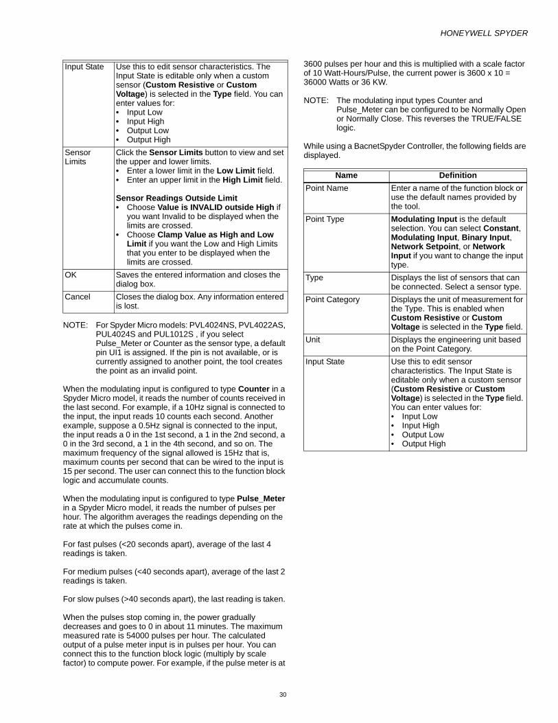
HONEYWELL SPYDER
30
NOTE: For Spyder Micro models: PVL4024NS, PVL4022AS, PUL4024S and PUL1012S , if you select Pulse_Meter or Counter as the sensor type, a default pin UI1 is assigned. If the pin is not available, or is currently assigned to another point, the tool creates the point as an invalid point.
When the modulating input is configured to type Counter in a Spyder Micro model, it reads the number of counts received in the last second. For example, if a 10Hz signal is connected to the input, the input reads 10 counts each second. Another example, suppose a 0.5Hz signal is connected to the input, the input reads a 0 in the 1st second, a 1 in the 2nd second, a 0 in the 3rd second, a 1 in the 4th second, and so on. The maximum frequency of the signal allowed is 15Hz that is, maximum counts per second that can be wired to the input is 15 per second. The user can connect this to the function block logic and accumulate counts.
When the modulating input is configured to type Pulse_Meter in a Spyder Micro model, it reads the number of pulses per hour. The algorithm averages the readings depending on the rate at which the pulses come in.
For fast pulses (<20 seconds apart), average of the last 4 readings is taken.
For medium pulses (<40 seconds apart), average of the last 2 readings is taken.
For slow pulses (>40 seconds apart), the last reading is taken.
When the pulses stop coming in, the power gradually decreases and goes to 0 in about 11 minutes. The maximum measured rate is 54000 pulses per hour. The calculated output of a pulse meter input is in pulses per hour. You can connect this to the function block logic (multiply by scale factor) to compute power. For example, if the pulse meter is at
3600 pulses per hour and this is multiplied with a scale factor of 10 Watt-Hours/Pulse, the current power is 3600 x 10 = 36000 Watts or 36 KW.
NOTE: The modulating input types Counter and Pulse_Meter can be configured to be Normally Open or Normally Close. This reverses the TRUE/FALSE logic.
While using a BacnetSpyder Controller, the following fields are displayed.
Input State Use this to edit sensor characteristics. The Input State is editable only when a custom sensor (Custom Resistive or Custom Voltage) is selected in the Type field. You can enter values for: • Input Low • Input High • Output Low • Output High
Sensor Limits
Click the Sensor Limits button to view and set the upper and lower limits. • Enter a lower limit in the Low Limit field. • Enter an upper limit in the High Limit field.
Sensor Readings Outside Limit • Choose Value is INVALID outside High if
you want Invalid to be displayed when the limits are crossed.
• Choose Clamp Value as High and Low Limit if you want the Low and High Limits that you enter to be displayed when the limits are crossed.
OK Saves the entered information and closes the dialog box.
Cancel Closes the dialog box. Any information entered is lost.
Name DefinitionPoint Name Enter a name of the function block or
use the default names provided by the tool.
Point Type Modulating Input is the default selection. You can select Constant, Modulating Input, Binary Input, Network Setpoint, or Network Input if you want to change the input type.
Type Displays the list of sensors that can be connected. Select a sensor type.
Point Category Displays the unit of measurement for the Type. This is enabled when Custom Resistive or Custom Voltage is selected in the Type field.
Unit Displays the engineering unit based on the Point Category.
Input State Use this to edit sensor characteristics. The Input State is editable only when a custom sensor (Custom Resistive or Custom Voltage) is selected in the Type field. You can enter values for: • Input Low • Input High • Output Low • Output High

HONEYWELL SPYDER
31
The following table defines the fields shown in the Advanced screen of a Modulating Input point.
NOTE:
— You can drag and drop IOs on to the wiresheet even when all pins are used up. Honeywell Spyder allows IOs to be dropped but they will not be assigned with a pin. Such IOs are termed as invalid IOs. A message indicating that the IO does not get a pin is displayed.
— When a modulating input is deleted, if it had a valid IO pin assigned, the freed pin is automatically assigned to any invalid modulating input or an invalid binary input.
— When a physical IO (Modulating input, Binary input, Modulating output, Binary output) with a valid IO pin is copied and pasted in the wiresheet, the resulting IO gets the same configuration as the source and a new available pin. If no free pin is available, the resulting IO becomes an invalid IO.
— When an invalid physical IO (Modulating input, Binary input, Modulating output, Binary output) is copied and pasted in the wiresheet, the resulting IO gets the same configuration as the source and it is also an invalid IO.
— When you copy and paste a modulating intput of type standard and custom sensors on the wiresheet, the same configuration is retained. Even though an On Board Pressure Sensor can be configured, it will not be as a consequence of the copy and paste action on the wiresheet.
Adding an Onboard Pressure SensorThe on-board pressure sensor is always assigned to the Universal Input # 0, in case where the model supports this fixed physical point, whether it is physically present or not.
NOTE: The number of On Board Pressure Sensors you can add are dependent on the Controller model selected. If you exceed the allowed limit of On Board Pressure Sensors in an application logic, you cannot configure the modulating inputs as On Board Pressure Sensor.
Sensor Limits Click the Sensor Limits button to view and set the upper and lower limits. • Enter a lower limit in the Low
Limit field. • Enter an upper limit in the High
Limit field. Sensor Readings Outside Limit • Choose Value is INVALID outside
High if you want Invalid to be displayed when the limits are crossed.
• Choose Clamp Value as High and Low Limit if you want the Low and High Limits that you enter to be displayed when the limits are crossed.
Advanced Displays the Bacnet object details. Object Name, Object Type, Object Instance are the fields provided. Object Name is automatically provided by the tool and can be edited. Object Instance number can also be edited. Object Type is a read only field and cannot be edited. If the GPU option in the advanced dialog box is set to True, Send Heartbeat is enabled.
OK Saves the entered information and closes the dialog box.
Cancel Closes the dialog box. Any information entered is lost.
Name DescriptionObject Name Displays the name of the modulating
input point. The object name can be edited.
Field Name Displays the name of the backend object created for the input point . It is non-editable.
Object Type Displays the object type as Modulating Input. It is non-editable.
Object Instance
A unique number that is automatically assigned to the object. This field is editable. If you try replacing the instance value with a value of your choice, the replacement is successful only if the value of your choice is not in use by any other object.
Name DefinitionSen Delta The Significant Event Notification
is also known as SEN Delta. The object is sent on the Bacnet Network whenever any field exceeds the SEN Delta. SEN Delta of zero (0) disables the feature.
Update Interval
The rate at which the input point is updated.
GPU Set the GPU of each modulating input to either True or False.• True means if the Modulating
Input is bound and it has not sent an update to the Bacnet network target in the GPU specified time then an alarm is generated and the Modulating Input is set to Invalid.
• False means the Modulating Input retains what was written to it until a Bacnet network source changes it or the Honeywell Spyder has a power outage or resets.
Send Heart Beat
The rate at which input points send data to the network.
Name Description

HONEYWELL SPYDER
32
Example: To the LonSpyder I model PVL6436A, if you add more than six modulating inputs in your logic, the seventh Modulating input you add is automatically configured as an On Board Pressure Sensor and is assigned to Pin0.
To add an Onboard Pressure Sensor:
1. Drag a Modulating Input from the Spyder Palette to the wiresheet.
2. Right-click the Modulating Input you just added and select Configure Properties.
3. Select On_Board_Pressure from the Type list. 4. Click OK to complete adding an On Board Pressure
Sensor.
Point Conversion
What do I convert To what do I
convert? How do I do it? What is the effect?Modulating Input Constant 1. Right-click the Modulating
input block and select Configure Properties.
2. Select Constant from the Point Type list.
3. Select a Point Category.4. Select Units to be used
within logic.5. Select Value.6. Click OK.
1. If the Modulating Input was connected to a slot of a function block, the slot is converted from Connector type to Constant.
2. IO pins used by the Modulating input are freed.
Modulating Input NCI 1. Right-click the Modulating input block and select Configure Properties.
2. Select Constant from the Point Type list.
3. Enter a Value.4. Select Share Point on
Network.5. Click OK.
1. The IO pins used by the Modulating input are freed.
2. A new NCI of type Snvt is created, deter-mined by the Point Category, Internal Data Type unit selected.
3. The new NCI is seen in the NVs table in the NV Configuration View.
Modulating Input Network Input (NVI)
1. Right-click the Modulating input block and select Configure Properties.
2. Select Network Input from the Point Type list.
3. Select a Point Category.4. Select Units to be used
within logic.5. Click OK.
1. The IO pins used by the Modulating input are freed.
2. A new NVI of type Snvt is created, deter-mined by the Point Category, Internal Data Type unit selected.
3. The new NVI is seen in the NVs table in the NV Configuration View.
Modulating Input Binary Input 1. Right-click the Modulating input block and select Configure Properties.
2. Select Binary Input from the Point Type list.
3. Select Type.4. Select Data Type.5. Click OK.
1. If there are no IO pins available for the target physical IO (in this case, the Binary input that is created), the point becomes an invalid IO.
2. A warning message appears indicating that there are no more pins to allocate, and an unassigned IO is created.
Modulating Input Network Setpoint
1. Right-click the Modulating input block and select Configure Properties.
2. Select Network Set-point from the Point Type list.
3. Select Type. 4. Click OK.
1. The IO pins used by the Modulating Input are freed.
2. The new setpoint input is seen in the Objects table in the Object Configuration View.
Modulating Input Network Input 1. Right-click the Modulating input block and select Configure Properties.
2. Select Network Input from the Point Type list.
3. Select Type. 4. Click OK.
1. The IO pins used by the Modulating Input are freed.
2. The new network input is seen in the Objects table in the Object Configuration View.
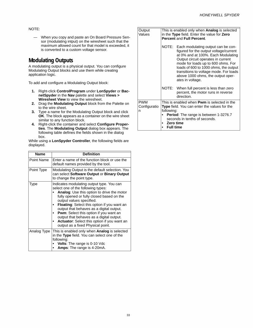
HONEYWELL SPYDER
33
NOTE:
— When you copy and paste an On Board Pressure Sen-sor (modulating intput) on the wiresheet such that the maximum allowed count for that model is exceeded, it is converted to a custom voltage sensor.
Modulating OutputsA modulating output is a physical output. You can configure Modulating Output blocks and use them while creating application logic.
To add and configure a Modulating Output block:
1. Right-click ControlProgram under LonSpyder or Bac-netSpyder in the Nav palette and select Views > Wiresheet View to view the wiresheet.
2. Drag the Modulating Output block from the Palette on to the wire sheet.
3. Type a name for the Modulating Output block and click OK. The block appears as a container on the wire sheet similar to any function block.
4. Right-click the container and select Configure Proper-ties. The Modulating Output dialog box appears. The following table defines the fields shown in the dialog box.
While using a LonSpyder Controller, the following fields are displayed.
Name DefinitionPoint Name Enter a name of the function block or use the
default names provided by the tool. Point Type Modulating Output is the default selection. You
can select Software Output or Binary Output to change the point type.
Type Indicates modulating output type. You can select one of the following types: • Analog: Use this option to drive the motor
fully opened or fully closed based on the output values specified.
• Floating: Select this option if you want an output that behaves as a digital output.
• Pwm: Select this option if you want an output that behaves as a digital output.
• Actuator: Select this option if you want an output as a fixed Physical point.
Analog Type This is enabled only when Analog is selected in the Type field. You can select one of the following:• Volts: The range is 0-10 Vdc • Amps: The range is 4-20mA.
Output Values
This is enabled only when Analog is selected in the Type field. Enter the value for Zero Percent and Full Percent.
NOTE: Each modulating output can be con-figured for the output voltage/current at 0% and at 100%. Each Modulating Output circuit operates in current mode for loads up to 600 ohms. For loads of 600 to 1000 ohms, the output transitions to voltage mode. For loads above 1000 ohms, the output oper-ates in voltage.
NOTE: When full percent is less than zero percent, the motor runs in reverse direction.
PWM Configuration
This is enabled when Pwm is selected in the Type field. You can enter the values for the following:• Period: The range is between 1-3276.7
seconds in tenths of seconds. • Zero time • Full time

HONEYWELL SPYDER
34
While using a BacnetSpyder Controller, the following fields are displayed.
Floating Motor Configuration
This is enabled when Floating is selected in the Type field.• Travel time • AutoSyncType: You can select one of the
following values: • None: Honeywell Spyder assumes the
motor is fully closed. • Sync Open: The motor is driven fully open. • Sync Closed: The motor is driven fully
closed. • AutoSyncInterval: The Auto
Synchronization Interval is configured from 0 to 255 hours in one hour increments. The timer is loaded and starts counting down right after power up reset and power up delay. When the timer expires, the motor is synchronized. This only applies if the user configured auto synchronization to be Sync Open or Sync Closed.
• PowerupSyncType: You can select one of the following values:
• None: Honeywell Spyder assumes the motor is fully closed.
• Sync Open: The motor is driven fully open. • Sync Closed: The motor is driven fully
closed. • PowerupDelay: The Power Up Delay is
configured from 0 to 3276.7 seconds in tenths of seconds. Zero (0) means no delay.
Motor Action This is enabled only when Floating is selected in the Type field. You can select one of the following values:• Direct • Reverse Reverse Action is configured for
— True = 100% = full closed, 0% = full open.
— False is the opposite.OK Saves the entered information and closes the
dialog box.Cancel Closes the dialog box. Any information entered
is lost.
Name DescriptionPoint Name Enter a name or use the default names
provided by the tool.Point Type Modulating Output is the default selection.
You can select Network Output, Modulating Output or Binary Output to change the point type.
Type Indicates modulating output type. You can select one of the following types: • Analog: Use this option to drive the motor
fully opened or fully closed based on the output values specified.
• Floating: Select this option if you want an output that behaves as a digital output.
• Pwm: Select this option if you want an output that behaves as a digital output.
• Actuator: Select this option if you want an output as a fixed Physical point.
Analog Type This is enabled only when Analog is selected in the Type field. You can select one of the following: • Volts: The range is 0-10 Vdc. • Amps: The range is 4-20mA.
Output Values This is enabled only when Analog is selected in the Type field. Enter the value for Zero Percent and Full Percent.
NOTE: Each modulating output can be configured for the output voltage/current at 0% and at 100%. Each Modulating Output circuit operates in current mode for loads up to 600 ohms. For loads of 600 to 1000 ohms, the output transitions to volt-age mode. For loads above 1000 ohms, the output operates in volt-age. When full percent is less than zero percent, the motor runs in reverse direction.
PWM Configuration
This is enabled when Pwm is selected in the Type field. You can enter the values for the following: • Period: The range is between 1-3276.7
seconds in tenths of seconds. • Zero time • Full time

HONEYWELL SPYDER
35
NOTE:
— You can drag the IOs on to the wiresheet even when all pins are used up. Honeywell Spyder allows IOs to be dropped but they are not assigned with a pin. Such IOs are termed as invalid IOs. A message indicating that the IO does not get a pin is displayed.
— When a Modulating output configured as Floating type is deleted, if it had a valid IO pin assigned, the freed pin is automatically assigned to any available invalid Modulating output configured as Floating type or to an invalid binary output.
— When a modulating output configured as PWM type is deleted, if it had a valid IO pin assigned, the freed pin is automatically assigned to any available invalid Mod-ulating output configured as PWM or to an invalid binary output.
— When a modulating output configured as Analog type is deleted, if it had a valid IO pin assigned, the freed pin is automatically assigned to any available invalid Modulating output configured as Analog type or to an invalid binary output.
— When a physical IO (Modulating input, Binary input, Modulating output, Binary output) with a valid IO pin is copied and pasted in the wiresheet, the resulting IO gets the same configuration as the source and a new available pin. If no free pin is available, the resulting IO becomes an invalid IO.
— When an invalid physical IO (Modulating input, Binary input, Modulating output, Binary output) is copied and pasted in the wiresheet, the resulting IO gets the same configuration as the source and it is also an invalid IO.
— When you copy and paste a modulating output on the wiresheet, the same configuration is retained. When copying an analog type, even if digital pins are present, a pin is not assigned. A pin is assigned only when a floating/pwn type is copied and pasted on the wiresheet or when it is dragged on to the wiresheet.
Adding an ActuatorAn actuator is a fixed physical point. The Actuator is always assigned to the Digital Output # 7 and 8, in case where the model supports this fixed physical point, whether it is physically present or not.
Example: If you are adding multiple modulating outputs in an application logic to the Lon model PVL6436A, by default, the first three are configured as analog points, the next six are configured as Pwm points. The seventh modulating output is configured as Actuator, if the model supports and is assigned to Pins DO7 and DO8.
To add an Actuator:
1. Drag a Modulating Output from the Spyder palette to the wiresheet.
2. Right-click the Modulating Output you just added and select Configure Properties.
3. Select Actuator from the Type list. 4. Select Floating Motor Configuration details. 5. Specify Motor Action. 6. Click OK to complete adding an Actuator.
Floating Motor Configuration
This is enabled when Floating is selected in the type field. • Travel time: • AutoSyncType: You can select one of
the following values: — None: Honeywell Spyder assumes
the motor is fully closed. — Sync Open: The motor is driven
fully open. — Sync Closed: The motor is driven
fully closed. • AutoSyncInterval: The Auto
Synchronization Interval is configured from 0 to 255 hours in one hour increments. The timer is loaded and starts counting down right after power up reset and power up delay. When the timer expires, the motor is synchronized. This only applies if the user configured auto synchronization to be Sync Open or Sync Closed.
• PowerupSyncType: You can select one of the following values: — None: Honeywell Spyder assumes
the motor is fully closed. — Sync Open: The motor is driven
fully open. — Sync Closed: The motor is driven
fully closed. • PowerupDelay: The Power Up Delay is
configured from 0 to 3276.7 seconds in tenths of seconds. Zero (0) means no delay.
Motor Action This is enabled only when Floating is selected in the Type field. You can select one of the following values: • Direct • Reverse
Reverse Action is configured for True = 100% = f ull closed, 0% = full open. False is the opposite.
Advanced Displays the Bacnet object details. Object Name, Object Type, Object Instance are the fields provided. Object Name is automatically provided by the tool and can be edited. Object Instance number can also be edited. Object Type is a read only field and cannot be edited. If the GPU option in the advanced dialog box is set to True, Send Heartbeat is enabled. If the Fail Detect Enabled is set to True, Udate Rate is enabled.
OK Saves the entered information and closes the dialog box.
Cancel Closes the dialog box. Any information entered is lost.
Name Description

HONEYWELL SPYDER
36
Point Conversion
What do I convert To what do I
convert? How do I do it? What is the effect?Modulating Output Binary Output 1. Right-click the Modulating
output block and select Configure Properties.
2. Select Binary Output from the Point Type list.
3. Click OK.
1. If there are no IO pins available for the target physical IO (in this case, the Binary output that is created), the point becomes an invalid IO.
2. A warning message appears indicating that there are no more pins to allocate, and an unassigned IO is created.
Modulating Output Network Output 1. Right-click the Modulating output block and select Configure Properties.
2. Select Network Output from the Point Type list.
3. Select a Point Category. 4. Select the Unit. 5. Click OK.
1. The IO pins used by the Modulating output are freed.
2. The new network output is seen in the Objects table in the Object Configuration View.

HONEYWELL SPYDER
37
SOFTWARE POINTSSoftware IOs are non-physical IOs that you can configure as Constants, Network Input, Network Setpoint, or Network Outputand use in your application logic.
ConstantsA constant input is a non-physical input which is not visible to the network. You can configure Constant blocks and use them while creating application logic in Bacnet Spyder.
To add and configure a network input block:
1. Right-click ControlProgram under Honeywell Spyder in the Nav palette and select Views > Wiresheet View to view the wiresheet.
2. Drag the Constant block from the Spyder Palette on to the wire sheet.
3. Type the desired name for the Constant block and click OK. The block appears as a container on the wire sheet similar to any function block.
4. Right-click the container and select Configure Proper-ties. The Constant dialog box appears. The following table defines the fields shown in the dialog box.
To define your own custom enumeration type for the software points:
1. Select Custom from the Sub-Category list. 2. Click the button next to the Sub-Category drop-down.
The Enum dialog box appears. 3. Click the check box Load from Standard list to load the
range from the standard list. or Click Add to create your own custom enumeration type. Enter the New Enum name and click Save.
4. Click OK.
NOTE: You can drag IOs on to the wiresheet even when all pins are used up. Honeywell Spyder allows IOs to be dropped but they are not assigned with a pin. Such IOs are termed as invalid IOs. A message indicating that the IO does not get a pin is displayed.
NOTE: You can add a Constant to a macro.
Name DescriptionPoint Name Type a name of the function block or
use the default names given by the tool.
Point Type Constant is the default selection. You can select Constant, Network Input, Network Setpoint, Binary Input or Modulating Input to change the point type.
Point Category Displays the unit of measurement for the Point Type.
Unit Displays the engineering unit based on the Point Category.
Sub-Category Displays the enumeration type for the software points. The field Unit is renamed as Sub-Category if the point category selection is unitless.
OK Saves the entered information and closes the dialog box.
Cancel Closes the dialog box. Any information entered is lost.
Name Description

HONEYWELL SPYDER
38
Point Conversion
Network InputsA network input is a non-physical input. You can configure Network Input blocks and use them while creating application logic in Bacnet Spyder.
To add and configure a network input block:
1. Right-click ControlProgram under Honeywell Spyder in the Nav palette and select Views > Wiresheet View to view the wiresheet.
2. Drag the Network Input block from the Spyder Palette on to the wire sheet.
3. Type the desired name for the Network Input block and click OK. The block appears as a container on the wire sheet similar to any function block.
What do I want to convert?
To what do I want to convert? How do I do it? What is the effect?
Constant Network Input 1. Right-click the Network input block and select Configure Properties.
2. Select Constant from the Point Type list.
3. Select a Point Category. 4. Click OK.
1. If the Functional block slot to which the point was connected was of type Constant/Connector, the slot is converted from Constant type to Connector but the link is retained.
2. If the functional block slot to which the point was connected was of type Connector only, the link is bro-ken.
3. A network input is created and added to the Objects table in the Object Configuration View.
Constant Network Setpoint 1. Right-click the Network input block and select Configure Properties.
2. Select Network Setpoint from the Point Type list.
3. Select a Point Category. 4. Click OK.
1. If the Functional block slot to which the point was connected was of type Constant/Connector, the slot is converted from Constant type to Connector but the link is retained.
2. If the Functional block slot to which the point was of type Constant only, the link is broken.
3. A new setpoint input is created and added to the Objects table in the Object Configuration View.
Constant Binary Input 1. Right-click the Network input block and select Configure Properties.
2. Select Binary Input from the Point Type list.
3. Select Type. 4. Select Data Type. 5. Click OK.
1. If the Functional block slot to which the point was connected was of type Constant/Connector, the slot is converted from Constant type to Connector but the link is retained.
2. If the Functional block slot to which the point was of type Constant only, the link is broken.
3. The resulting physical IO object (Binary input in this case) gets any free IO pin available. If no pin is available, the resulting physical IO becomes an invalid IO (IO with no pin).
Constant Modulating Input 1. Right-click the Network input block and select Configure Properties.
2. Select Modulating Input from the Point Type list.
3. Select Type. 4. Select Data Type. 5. Click OK.
1. If the Functional block slot to which the point was connected was of type Constant/Connector, the slot is converted from Constant type to Connector but the link is retained.
2. If the Functional block slot to which the point was of type Constant only, the link is broken.
3. The resulting physical IO object (Modulating input in this case) gets any free IO pin available. If no pin is available, the resulting physical IO becomes an invalid IO (IO with no pin).

HONEYWELL SPYDER
39
4. Right-click the container and select Configure Proper-ties. The Network Input dialog box appears. The fol-lowing table defines the fields shown in the dialog box.
The following table defines the fields shown in the Advanced screen of a Network Input point.
To define your own custom enumeration type for the software points:
1. Select Custom from the Sub-Category list. 2. Click the button next to the Sub-Category drop-down.
The Enum dialog box appears. 3. Click the check box Load from Standard list to load
the range from the standard list. or Click Add to create your own custom enumeration type. Enter the New Enum name and click Save.
4. Click OK.
NOTE: You can add a Network Input with Point Type as Constant to a macro.
Name DescriptionPoint Name Type a name of the function block or
use the default names given by the tool.
Point Type Network Input is the default selection. You can select Constant, Network Input, Network Setpoint, Binary Input or Modulating Input to change the point type.
Point Category Displays the unit of measurement for the Point Type.
Unit Displays the engineering unit based on the Point Category.
Sub-Category Displays the enumeration type for the software points. The field Unit is renamed as Sub-Category if the point category selection is unitless.
Advanced Displays the Bacnet object details. Object Name, Object Type, Object Instance are the fields provided. Object Name is automatically provided by the tool and can be edited. Object Instance number can also be edited. Object Type is a read only field and cannot be edited.
OK Saves the entered information and closes the dialog box.
Cancel Closes the dialog box. Any information entered is lost.
Name DescriptionObject Name Displays the name of the network
input point. The object name can be edited.
Field Name Displays the name of the backend object created for the input object. It is non-editable.
Object Type Displays the object type as Network Input. This field is non-editable.
Object Instance A unique number that is automatically assigned to the object. This field is editable. If you try replacing the instance value with a value of your choice, the replacement is successful only if the value of your choice is not in use by any other object.
Proposed Type Enables you to selct the object type as Analog Value or Binary Value.
Update Interval The rate at which the input object is updated.
Fail Detect Enabled Set the Fail Detect Enabled of each object input to either True or False.• True means if the Object Input is
bound and it has not received an update from the Bacnet network source in the fail detect time then an alarm is generated and the Object Input is set to Invalid.
• False means the Object Input retains what was written to it until a Bacnet network source changes it or the Honeywell Spyder has a power outage or resets.
Update Rate The polling rate to update Object values of Object components.
Name Description

HONEYWELL SPYDER
40
Point Conversion
Network SetpointsA network setpoint is a non-physical input. You can configure Network Setpoint blocks and use them while creating application logic in Bacnet Spyder.
To add and configure a network input block:
1. Right-click ControlProgram under Honeywell Spyder in the Nav palette and select Views > Wiresheet View to view the wiresheet.
2. Drag the Network Setpoint block from the Spyder Pal-ette on to the wire sheet.
3. Type the desired name for the Network Setpoint block and click OK. The block appears as a container on the wire sheet similar to any function block.
4. Right-click the container and select Configure Proper-ties. The Network Setpoint dialog box appears. The following table defines the fields shown in the dialog box.
What do I want to convert?
To what do I want to convert? How do I do it? What is the effect?
Network Input Constant 1. Right-click the Network input block and select Configure Properties.
2. Select Constant from the Point Type list.
3. Select a Point Category. 4. Click OK.
1. If the functional block slot to which the point was connected was of type Constant/Connector, the slot is converted from Con-nector type to Constant and the link is retained.
2. If the functional block slot to which the point was connected was of type Connector only, the link is broken.
Network Input Network Setpoint 1. Right-click the Network input block and select Configure Properties.
2. Select Network Setpoint from the Point Type list.
3. Select a Point Category. 4. Click OK.
1. If the point is connected to any functional block, the functional blocks slot type and links are retained.
2. A new setpoint input is created and added to the Objects table in the Object Configuration View.
Network Input Binary Input 1. Right-click the Network input block and select Configure Properties.
2. Select Binary Input from the Point Type list.
3. Select Type. 4. Select Data Type. 5. Click OK.
1. If the point is connected to any functional block, the functional block slot type and links are retained.
2. The resulting physical IO object (Binary input in this case) gets any free IO pin available. If no pin is available, the resulting physical IO becomes an invalid IO ( IO with no pin).
Network Input Modulating Input 1. Right-click the Network input block and select Configure Properties.
2. Select Modulating Input from the Point Type list.
3. Select Type. 4. Select Data Type. 5. Click OK.
1. If the point is connected to any functional block, the functional block slot type and links are retained.
2. The resulting physical IO object (Modulating input in this case) gets any free IO pin available. If no pin is available, the resulting physical IO becomes an invalid IO (IO with no pin).
Name DescriptionPoint Name Type a name of the function block or
use the default names given by the tool.
Point Type Network Setpoint is the default selection. You can select Constant, Network Input, Network Setpoint, Binary Input or Modulating Input to change the point type.
Point Category Displays the unit of measurement for the Point Type.
Unit Displays the engineering unit based on the Point Category.

HONEYWELL SPYDER
41
The following table defines the fields shown in the Advanced screen of a Network Setpoint.
To define your own custom enumeration type for the software points:
1. Select Custom from the Sub-Category list. 2. Click the button next to the Sub-Category drop-down.
The Enum dialog box appears. 3. Click the check box Load from Standard list to load the
range from the standard list. or Click Add to create your own custom enumeration type. Enter the New Enum name and click Save.
4. Click OK.
NOTE: You can add a Network Setpoint with Point Type as Constant to a macro.
Sub-Category Displays the enumeration type for the software points.The field Unit is renamed as Sub-Category if the point category selection is unitless.
Advanced Displays the Bacnet object details. Object Name, Object Type, Object Instance are the fields provided. Object Name is automatically provided by the tool and can be edited. Object Instance number can also be edited. Object Type is a read only field and cannot be edited.
OK Saves the entered information and closes the dialog box.
Cancel Closes the dialog box. Any information entered is lost.
Name Description
Name DescriptionObject Name Displays the name of the network
setpoint. The object name can be edited.
Field Name Displays the name of the backend object created for the setpoint object. It is non-editable.
Object Type Displays the object type as Network Setpoint. This field is non-editable.
Object Instance A unique number that is automatically assigned to the object. This field is editable. If you try replacing the instance value with a value of your choice, the replacement is successful only if the value of your choice is not in use by any other object.
Update Interval The rate at which the setpoint object is updated.
Proposed Type Enables you to selct the object type as Analog Value or Binary Value.

HONEYWELL SPYDER
42
Point Conversion
Network OutputsWhile in the midst of creating an ControlProgram/Program, if you need to quickly add an Network Output, use the Software Outputs item on the Spyder Palette.
You cannot add an Network Output point to a macro.
To add and configure a Network output block:
1. Right-click ControlProgram under BacnetSpyder in the Nav palette and select Views > Wiresheet View to view the wiresheet.
2. Drag the Network Output block from the Spyder Palette on to the wire sheet.
3. Type the desired name for the Network Output block and click OK. The block appears as a container on the wire sheet similar to any function block.
4. Right-click the container and select Configure Proper-ties. The Network Output dialog box appears. The fol-lowing table defines the fields shown in the dialog box.
What do I want to convert?
To what do I want to convert? How do I do it? What is the effect?
Network Setpoint Constant 1. Right-click the Network setpoint block and select Configure Prop-erties.
2. Select Constant from the Point Type list.
3. Select a Point Category. 4. Click OK.
1. If the functional block slot to which the point was connected was of type Constant/Connector, the slot is con-verted from Connector type to Con-stant but the link is retained.
2. If the functional block slot to which the point was connected was of type Connector only, the link is broken.
Network Setpoint Network Input 1. Right-click the Network setpoint block and select Configure Prop-erties.
2. Select Network Input from the Point Type list.
3. Select a Point Category. 4. Click OK.
1. If the point is connected to any func-tional block, the functional block slots and links are retained.
2. A new network input is created and added to the Objects table in the Object Configuration View.
Network Setpoint Binary Input 1. Right-click the Network setpoint block and select Configure Prop-erties.
2. Select Binary Input from the Point Type list.
3. Select Type. 4. Select Data Type. 5. Click OK.
1. If the point is connected to any func-tional block, the functional block slot type and links are retained.
2. The resulting physical IO object (Binary input in this case) gets any free IO pin available. If no pin is avail-able, the resulting physical IO becomes an invalid IO ( IO with no pin).
Network Setpoint Modulating Input 1. Right-click the Network setpoint block and select Configure Prop-erties.
2. Select Modulating Input from the Point Type list.
3. Select Type. 4. Select Data Type. 5. Click OK.
1. If the point is connected to any func-tional block, the functional block slot type and links are retained.
2. The resulting physical IO object (Modulating input in this case) gets any free IO pin available. If no pin is available, the resulting physical IO becomes an invalid IO (IO with no pin).
Name DescriptionPoint Name Type a name of the function block or
use the default names given by the tool.
Point Type Network Setpoint is the default selection. You can select Constant, Network Input, Network Setpoint, Binary Input or Modulating Input to change the point type.
Point Category Displays the unit of measurement for the Point Type.
Unit Displays the engineering unit based on the Point Category.

HONEYWELL SPYDER
43
The following table defines the fields shown in the Advanced screen of a Network Output point.
To define your own custom enumeration type for the software points:
1. Select Custom from the Sub-Category list. 2. Click the button next to the Sub-Category drop-down.
The Enum dialog box appears. 3. Click the check box Load from Standard list to load
the range from the standard list. or Click Add to create your own custom enumeration type. Enter the New Enum name and click Save.
4. Click OK.
Point Conversion
Sub-Category Displays the enumeration type for the software points. The field Unit is renamed as Sub-Category if the point category selection is unitless.
Advanced Displays the Bacnet object details. Object Name, Object Type, Object Instance are the fields provided. Object Name is automatically provided by the tool and can be edited. Object Instance number can also be edited. Object Type is a read only field and cannot be edited.
OK Saves the entered information and closes the dialog box.
Cancel Closes the dialog box. Any information entered is lost.
Name DescriptionObject Name Displays the name of the network output
point. The object name can be edited.Field Name Displays the name of the backend object
created for the output object. It is non-editable.
Object Type Displays the object type as Network Output. This field is non-editable.
Object Instance A unique number that is automatically assigned to the object. This field is editable. If you try replacing the instance value with a value of your choice, the replacement is successful only if the value of your choice is not in use by any other object.
Update Interval The rate at which the output object is updated.
Name DescriptionProposed Type Enables you to selct the object type as
Analog Value or Binary Value.Sen Delta The Significant Event Notification is
also known as SEN Delta. The object is sent on the Bacnet Network whenever any field exceeds the SEN Delta. SEN Delta of zero (0) disables the feature.
GPU Set the GPU of each object output to either True or False.• True means if the Object Output is
bound and it has not sent an update to the Bacnet network target in the GPU specified time then an alarm is generated and the Object Output is set to Invalid.
• False means the Object Output retains what was written to it until a Bacnet network source changes it or the Honeywell Spyder has a power outage or resets.
Send Heart Beat The rate at which output objects send data to the network.
Name Description

HONEYWELL SPYDER
44
What do I want to convert?
To what do I want to convert? How do I do it? What is the effect?
Network Output Binary Output 1. Right-click the Network output block and select Configure Prop-erties.
2. Select Binary Output from the Point Type list.
3. Click OK.
1. If there are any free pins avail-able, the resulting physical IO object gets an IO pin. If no pin is available, the result-ing physical IO becomes an invalid IO (IO with no pin).
2. If the point is connected to any functional block, the functional block slot type and links are retained.
Network Output Modulating Output 1. Right-click the Network output block and select Configure Prop-erties.
2. Select Modulating Output from the Point Type list.
3. A warning message appears. Click Yes to continue.
4. Click OK.
1. If there are any free pins avail-able, the resulting physical IO object gets an IO pin. If no pin is available, the result-ing physical IO becomes an invalid IO (IO with no pin).
2. If the point type is connected to any functional block, the function block slot type and links are retained.

HONEYWELL SPYDER
45
EDITING SOFTWARE POINTSTo edit a software point in Lon or Bacnet network:
1. Browse to Station > Config > Drivers > LonNetwork > LonSpyder. or Browse to Station > Config > Drivers > BacnetNet-work > BacnetSpyder.
2. Select ControlProgram > Views > NV Configuration View for Lon. or Select ControlProgram > Views > Object Configura-tion View for Bacnet.
3. The summary page appears with a list of pre-pro-grammed Mandatory, Fixed, and Custom NVs/Objects and Software points.
4. Select the software point you want to edit from the bot-tom half of the Object Configuration View and click the Edit Point button. The Configure Properties dialog box appears.
5. Click OK to save the changes or Cancel to close the Configure Properties dialog box without saving the changes.
Network Input
Network Setpoint
Name DefinitionPoint Name The name of the software point.Point Type Enables you to select Constant, Network Input, Network Setpoint, Binary Input or
Modulating Input.Point Category Select a unit of measurement for the Point Type.Unit to be used within Logic Select the engineering unit based on the Point Category.Sub-Category Select the enumeration type for the software points. The field Unit to be used within logic is
renamed as Sub-Category if the Point Category selection is Unitless.Value This field is enabled when the Point Type is Network Setpoint or Constant. The field enables
you to provide a setpoint or constant input value.Advanced Object Name is automatically provided by the tool and can be edited. Object Instance number
can also be edited. Object Type is a read only field and cannot be edited.
Name DefinitionPoint Name The name of the software point.Point Type Enables you to select Constant, Network Input, Network Setpoint, Binary Input or Modulating
Input.Point Category Select a unit of measurement for the Point Type.Unit to be used within Logic Select the engineering unit based on the Point Category.Sub-Category Select the enumeration type for the software points. The field Unit to be used within logic is
renamed as Sub-Category if the Point Category selection is unitless.Value Enables you to provide a setpoint input value. Check the Configure Invalid option to disable the
Value field.Advanced Object Name is automatically provided by the tool and can be edited. Object Instance number can
also be edited. Object Type is a read only field and cannot be edited.

HONEYWELL SPYDER
46
Constant
Network Output
Name DefinitionPoint Name The name of the software point.Point Type Enables you to select Constant,
Network Input, Network Setpoint, Binary Input or Modulating Input.
Point Category Select a unit of measurement for the Point Type.
Unit to be used within logic
Select the engineering unit based on the Point Category.
Sub-Category Select the enumeration type for the software points. The field Unit to be used within logic is renamed as Sub-Category if the Point Category selection is Unitless.
Value Enables you to provide a constant input value.
Advanced Object Name is automatically provided by the tool and can be edited. Object Instance number can also be edited. Object Type is a read only field and cannot be edited.
Name DefinitionPoint Name The name of the software point. Point Type Enables you to select Constant,
Network Input, Network Setpoint, Binary Input or Modulating Input.
Point Category Select a unit of measurement for the Point Type.
Unit to be used within logic
Select the engineering unit based on the Point Category.
Sub-Category Select the enumeration type for the software points. The field Unit to be used within logic is renamed as Sub-Category if the Point Category selection is Unitless.
Advanced Object Name is automatically provided by the tool and can be edited. Object Instance number can also be edited. Object Type is a read only field and cannot be edited.
Name Definition

HONEYWELL SPYDER
47
NETWORK VARIABLESA Network Variable (NV) is a data item such as a temperature, a switch value or actuator state. NVs can be thought of simply as point parameters. LonMark functional profiles define Standard Network Variable Types (SNVTs), but additional non-standard NVs are usually available, depending on the device, to store additional non-standard data.
There are three categories of NVs that the Honeywell Spyder supports. They are:
• Mandatory: Mandatory NVs are the default NVs compulsorily present in a Lon Spyder device.
• Fixed: You can use Fixed Dropable NVs while creating an application logic but can edit only its Internal Data Type. You can also display Fixed Dropable NVs on the wiresheet.
• Custom: Custom NVs are the NVs you create while creating an application logic. They can be created, edited, and deleted based on your requirements.
The following is a list of mandatory and fixed NVs supported by Spyder.
NOTE: Make sure that Mandatory and Fixed NVs should be created as per the model selected. If you expose the point of such fixed or droppable NVs which are removed in the next selected model ( the reason could be that the next selected model does not sup-port the NV) then that point becomes an invalid point. Note: The Spyder tool permits downloading or uploading network and internal data type information of all NV fields.
The LonSpyder provides the following four built-in functions that enable you to connect function blocks with other function blocks.
• NVI - Network Variable Inputs • NVO - Network Variable Output • NCI - Network Configuration Input • Many to One NV - Many to One Network Variable The Honeywell Spyder provides built-in functions, Network Variable Inputs, to allow the selection of variables that are available from/to the network. The configured network variables are mapped to the Function Block memory space to be used by any Function Block. Each Network variable may be configured with a name.
Viewing the List of Network Variables1. Browse through to Station > Config > Drivers > Lon-
Network > LonSpyder. 2. Select ControlProgram > Views > NV Configuration
View. The summary page appears with a list of pre-pro-grammed Mandatory, Fixed, and Custom NVs in a tabu-lar format. The table has the following columns:
— NV Name: The name of the network variable.— Type: Indicates if the NV is of type NVI, NVO, NCI or
Many to One NV. — Category: Indicates if the NV is Mandatory, Fixed,
Fixed Dropable, or Custom. — NV Container: Indicates where the NV is used.
3. The bottom half of the NV Configuration View displays the software points available on the wiresheet in a tabu-lar format. The table has the following columns:
— Point Name: The name of the software point (Network Input/Network Setpoint/Network Output) as it appears on the wiresheet.
— Field Names: Indicates if the NV is of type NVI, NVO, NCI or Many to One NV.
— Point Container: Indicates where the software point is used. All software points that are used in a Program within an application are also listed.
NOTE:
— Mandatory NVs cannot be used in the application logic.
— Mandatory NVs cannot be edited or deleted.— In a Fixed NV, only Internal Data Type can be
modified.— Custom NV is the user defined NV. A Custom NV
can be edited or deleted. — Fixed NVs marked as Fixed_Dropable can be
exposed on the wiresheet. Other fixed NVs can-not be exposed as points.
NvName Data Type NV TypenroPgmVer UNVT_pgmVer MandatorynvoNodeStatus SNVT_obj_status MandatorynviFileRequest SNVT_file_req MandatorynvoFileStatus SNVT_file_status MandatorynviFilePos SNVT_file_pos MandatorynviNodeRequest SNVT_obj_request MandatorynvoConfigError UNVT_configError MandatorynciApplVerNew UCPT_applVerNew MandatorynviDebugIndex UNVT_debugIndex MandatorynvoDebug1 UNVT_debug MandatorynvoDebug2 UNVT_debug MandatorynciDeviceName UCPT_devName MandatorynviInUse UNVT_inUse MandatorynvoAlarmH UNVT_alarm MandatorynvoAlarmStatus UNVT_alarmStatus MandatorynvoError UNVT_error MandatorynciAlarmInhibit UCPT_alarmInhibit MandatorynciSndHrtBt SCPTmaxSendTime MandatorynciRcvHrtBt SCPTmaxRcvTime MandatorynvoWMCommError UNVT_WMCommError MandatorynciUICalOffset UCPT_uiCalOffset FixednviTimeSet SNVT_time_stamp FixednvoTime SNVT_time_stamp FixednvoIO1 UNVT_io1 FixednvoIO2 UNVT_io2 FixednvoIO3 UNVT_io3 FixednviManVal UNVT_manVal Fixed

HONEYWELL SPYDER
48
— For each point that is copied and pasted on the wiresheet, a new NV of SNVT type nearest to the selected data type is created automatically.
— When a user changes the device model, if the name of a custom NV clashes with a fixed NV name in the target model, Honeywell Spyder gen-erates a new unique name for the custom NV and creates the new fixed NV
Group NVsYou can group multiple points spread across NVs into a single new NV or add it to an existing one. The points must be available on the wiresheet to make such a grouping possible. Multiple points of an NV of the type NVI and NCI can be grouped together to create a new NV. The new NV created can be saved as an NVI or NCI. When one or more NVs are grouped.
Also, invalid points can be grouped with fields of another NV to create a new NV.
You can also group a single point belonging to an NV. In this case a new NV is created
NOTE: The Group as NV option is not available for software points of type:
— Network Output (NVO points) — ManyToOneNV— Network Input/Network Setpoint— Software points of a ManyToOneNV if at least one
or whose network datatype of the corresponding field is configured as bit field is selected
— Fixed NV fields exposed as points To group fields as NVs:
1. On the NV Configuration View, select the fields that you want to group from the Software points available on wiresheet list.
NOTE: Use the CTRL key on your keyboard to select the dif-ferent fields you want to group.
2. Click the Group as NV button. The Confirmation dialog box appears, if you are trying to group fields belonging to NVI or NCI. Also, the fields will be deleted from the NVs from which they are being selected. If a field was the only field in an NV, and it was selected to be grouped as an NV, the NV from which it is being selected is deleted. You will not see this dialog box if you are grouping fields of NVOs.
3. Click OK. The Group as NV dialog box appears. 4. Fill the necessary information in the fields as explained
in the following table.
5. Click OK. The new NV is created and appears in the NVs list in the NV Configuration View. If you select Add to an existing NV, the fields are added to the existing NV and can be seen in the NVs list.
Name DefinitionGroup as New NV
Select this option if you want to save the fields you want to group as a new NV. In this case, you can enter a new NV Name.
Note: The new NV is created on the same folder on which the Group as NV option is invoked. Example: If you have a ControlProgram which has an Application2 residing in Application1, if you group points on the NV Configuration View of Application2, the new NV is created in the Application2 folder. However, if you grouped NVs on the NV Configuration View of the Application1, the new NV is created in the Application1 folder.
Add to Existing NV
Select this option if you want to add the points you want to group to an existing NV. In this case, you can select an existing custom NVI/NCI from the NV Name list.
On selecting this option, the fields of the NV to which the new points will be added are listed in the Fields Properties table.
Note: In the case where the selected NVI was of a SNVT type, the NV is converted to a UNVT after grouping of points is done.
NV Name The name that you can configure this NV with.NV Type The NV type you want to save the selected
fields as. You can choose NVI or NCI.Fields Properties
Displays the following properties for each field:
• Field Name • Data Category • Network Data Type • Internal Data Type
Up Arrow Use this button to reorder a field.Down Arrow
Use this button to reorder a field.
Field Name User defined field name.Data Category
Select the data type for the NV fields.
Network Data Type
It is the engineering unit received by the Honeywell Spyder controller. Specify the Network Data Type. Based on data category selected, the drop-down list changes.
Internal Data Type
It is the unit(s) of the output of the Network Variable. Specify the Internal Data Type. Based on data category selected, the drop-down list changes.
Value You can edit this option for an NCI.UNVT Name
Enter UNVT Name in case you are creating a new NVI.

HONEYWELL SPYDER
49
The following table summarizes how you can group a point(s) of an NV.
Network Variable Input The Network Variable Input (NVI) converts a raw network variable input into a value(s) that can be used by other function blocks.
NOTE: The maximum limit of the fields is based on the memory limitation of a selected controller model and NV size cannot exceed 31 bytes.
Each field is converted from Network Data Type to Internal Data Type engineering units. Network Data Type is the engineering unit received by the Honeywell Spyder controller. Internal Data Type is the unit(s) of the output of the Network Variable.
Example: Programming the Network Data Type to be SNVTtempp, and the Internal Data Type to be DegF, converts network temperatures of type SNVTtempp into DegF for use by the Function Blocks.
Adding an NVIYou can add an NVI from:
• NV Configuration View • HoneywellSpyder Palette
Adding an NVI from the NV Configuration ViewTo add a new Network Variable Input:
1. Navigate to Station > Config > Drivers > LonNetwork > LonSpyder.
2. Select ControlProgram > Views > NV Configuration View. The summary page appears with a list of pre-pro-grammed Mandatory, Fixed, and Custom NVs.
NOTE: If adding an NVI to a Program, browse through to the appropriate Program on the Nav palette.
3. Click Add NV. The New NV dialog box appears. Select Network Variable Input.
4. Click OK. The Add NVI dialog box appears. Select Net-work Variable Input.
5. Fill the necessary information in the fields and click OK to complete adding an NVI. The NVI is displayed in the NVs table.
NOTE: You cannot add an NVI to a macro. You can only add a Constant point to a macro.
— You cannot add a Software Output to a macro.
NVI NCI NVO
Valid Software
Input Point
Invalid Software
Input PointConstant
Point
Valid Network Output Point
Invalid Network Output point
NVI Yes Yes No Yes Yes Yes No NoNCI Yes Yes No Yes Yes Yes No NoValid Software Input Point
Yes Yes No Yes Yes Yes No No
Invalid Software Input Point
Yes Yes No Yes Yes Yes No No
Constant Point Yes Yes No Yes Yes Yes No NoNVO No No Yes No No No Yes Yes
Name DefinitionNVName The name that you can configure this NVI with.Fail Detect Set the Fail Detect of each NVI to either True or
False. • True: if the Network Variable Input is bound
and it has not received an update from the Lon network source in the fail detect time, then an alarm is generated and the Network Variable Input is set to Invalid.
• False: the Network Variable Input will retain what was written to it until a Lon network source changes it or the Honeywell Spyder has a power outage or resets.
Copy NV From
Enables you to select Standard NVs or User Defined NVs (NVs you created and saved earlier).
Standard NV
If you select Standard NV, you can choose a list of available NVs from the Select list. Standard NVs are pre-defined NVs known as SNVTs.
Custom NV If you select Custom you can choose a list of available NVs from the Select list. NVs you have created. This is taken from UNVT Name field.
Fields Properties
Displays the following properties for each field: • Field Name • Data Category • Network Data Type • Internal Data Type
Add Field Use this button to add a field. You can add a maximum of 99 fields.
Delete Field Use this button to delete a field.

HONEYWELL SPYDER
50
NOTE: You can create new NVs even if the NV count, field count, or unit stores count has been exceeded. Hon-eywell Spyder displays a message informing the same but allows creation of NVs.
Exposing an NVI field from the NV Configuration ViewTo expose the NV fields you have added:
1. Expand the NVI in the table to display the fields. Select the fields you want to display on the wiresheet and click the Show on wiresheet as Points button or Drag and drop the fields you want to display on the
wiresheet on to Software Points available on wiresheet list at the bottom of your screen on the right side. The Add Points dialog box appears.
2. Click OK. The fields you have selected appear on the Software Points available on wiresheet list at the bot-tom of your screen on the right side. The field name dis-plays the NV Name. Field Name information. If you do not select point to be displayed on the wiresheet, the NV is added but is not visible on the wiresheet.
3. Click Cancel if you do not wish to continue adding an NVI.
Adding an NVI from the Spyder PaletteWhile in the midst of creating an ControlProgram/Program, if you need to quickly add an NVI, use the Software Inputs item on the Spyder Palette.
NOTE: You cannot add an NVI to a macro. You can only add a Constant point to a macro.
To add an NVI to an ControlProgram/Application:
1. On the Spyder Palette, expand the SoftwarePoints folder. If the Spyder Palette is not visible on the left side of your screen, on the Menu bar, click Windows > Side-bars > Palette to display the Palette.
2. Drag and drop a Network Input to the wiresheet of an ControlProgram/Application. The Name dialog box appears.
3. Enter a name for the point and click OK.4. Right click the Network Input point you have just added
and select Configure Properties. The Configure Properties dialog box appears.
5. Enter/select the following:— Point Name: Enter a name for the point.— Point Category: Select a category.— Unit to be used within Logic: Select the unit for the
Point Category chosen.— Value: This is disabled.
6. Click OK to complete adding an NVI.
NOTE: When you create an NV using the Spyder Palette on the wiresheet, by default, the fields are exposed and you do not have to manually expose the fields of the NVI on the wiresheet.
Connecting NVIsOnce you have created an NVI, you can connect an NVI to an NVO/Function Block or Physical point by left-clicking on the output of an NVI and dragging your mouse to the input of an NVO/Function Block or Physical point.
You can group multiple points spread across NVs into a single new NV or add it to an exisitng one. The points must be available on the wiresheet to make such a grouping possible. Multiple points of an NV of the type NVI and NCI can be grouped together to create a new NV. The new NV created can be saved as an NVI or NCI. When one or more NVs are grouped.
Also, invalid points can be grouped with fields of another NV to create a new NV.
You can also group a single point belonging to an NV. In this case a new NV is created.
Edit Selected Field
Field Name Enter a name for the field. The default names of fields being Field_x, where x is from 1 to 99.
Data Category
Select the data type for the NV fields.
Network Data Type
It is the engineering unit received by the Honeywell Spyder controller. Specify the Network Data Type. Based on data category selected, the drop-down list changes.
Internal Data Type
It is the unit(s) of the output of the Network Variable. Specify the Internal Data Type. Based on data category selected, the drop-down list changes.
UNVT Name
Enter UNVT Name in case you are creating a new NVI.
>> Click this button to view the Facets Details Viewer for the network/internal data type.The following information is displayed:• Minimum – The minimum limit for selected
unit • Maximum– The maximum limit for selected
unit OR
• Range - Indicates the possible enumeration with their ordinal for a selected unit.
• Units - Indicates the units symbol for the selected unit (If it shows null, it means the unit symbol is not applicable there )
• Type - Indicates the data type size for selected unit F32 - 4 Bytes U16 – Unsigned 2 bytes S16 – Signed 2 bytes U8 – Unsigned byte S8 – Signed byte E8 - Enumerated byte UB – Unsigned bit
• Resolution - Scaling factor for the selected Unit. When a value is written to controller, the value is divided by the value specified in the Resolution field and when it is read from the controller, it is multiplied by the Resolution value before it is displayed in Niagara.
• Precision - Precision for the selected Unit

HONEYWELL SPYDER
51
NOTE: The Group as NV option is not available for software points of type:
— Software Output (NVO points) — ManyToOneNV— Network Input/Network Setpoint— Software points of a ManyToOneNV if at least one
or whose network data type of the corresponding field is configured as bit field is selected
— Fixed NV fields exposed as points
Grouping Points of type NVIYou can group two or more points of type NVI, NCI, valid software input point, invalid software input point, or software input point configured as constant to:
— Create a new NVI — Add to an existing NVI— Create a new NCI — Add to an existing NCI
When grouping to create a new NVI/NCI, the number of fields of the new NVI equals the number of software points selected for grouping. When you group points to add to an existing NVI/NCI, the selected software output points are added to the existing fields of the selected target NVI/NCI. The new/edited NVI/NCI appears in the upper pane in the list of NVs in the NV Configuration View. The lower pane in the NV Configuration View displays the list of all NVs with which a particular software output has been grouped.
The result of such a grouping is that the previous NVI/NCI is modified such that the corresponding field to this point is removed from the NV. The NV is deleted if the NV was a single field NV. This happens when points selected are already attached to an existing NV.
NOTE:
— If you group invalid software input points (an invalid NVI point) to form an NVI/NCI, the invalid NVI point is converted to a valid NVI/NCI point.
— When a software input point configured as a Constant is grouped to form an NVI or NCI, the software point is converted to a NVI/NCI point and any links from that point to functional blocks slots is broken. Such func-tional block slots are converted to Connector type of slots. he links are broken only when the target prop-erty type in the function blocks is CONSTANT_ONLY, else, target property type is converted to CONNEC-TOR and the link is retained.
— The result of copying and pasting an invalid Network input/setpoint/output point in the wiresheet is the cre-ation of an invalid Network input/setpoint/output point.
— When a folder contains some software points(NVI/NCI/NVO points) whose NVs are present in other fold-ers (other than its child folders), the points become invalid as the reference to the NV is lost.
— If points selected for grouping have a mixture of soft-ware input and output points, Group as NV option is not available
The following table summarizes how you can group a point(s) of a source NV to form a target NV.
To group points of NVIs:
1. On the NV Configuration View, select the fields that you want to group from the Software points available on wiresheet list.
NOTE: Use the CTRL key on your keyboard to select the dif-ferent fields you want to group.
2. Click the Group as NV button. The Confirmation dia-log box appears. The fields are deleted from the NVs from which they are being selected. If you select a field from an NV (for grouping) in which it was the only field, the NV from which it is being selected is deleted.
3. A message appears warning you that if the selected point is attached to an NV, grouping will delete that point from that NV. Click OK. The Group as NV dialog box appears.
Source NV Points
Target NV
NVI NCI NVO
Valid Software
Input Point
Invalid Software
Input PointConstant
Point
Valid Network Output Point
Invalid Network Output point
NVI Yes Yes No Yes Yes Yes No NoNCI Yes Yes No Yes Yes Yes No NoValid Software Input Point
Yes Yes No Yes Yes Yes No No
Invalid Software Input Point
Yes Yes No Yes Yes Yes No No
Constant Point Yes Yes No Yes Yes Yes No NoNVO No No Yes No No No Yes Yes

HONEYWELL SPYDER
52
4. Fill the necessary information in the fields as explained in the following table.
5. Click OK. The new NV is created and appears in the NVs list in the NV Configuration View. If you select Add to an existing NV, the fields are added to the existing NV and can be seen in the NVs list.
Network Configuration InputNCI is a Network Configuration Input.
Adding an NCIYou can add an NCI from:
• NV Configuration View • HoneywellSpyder Palette
Adding an NCI from the NV Configuration ViewTo add a new Network Configuration Input:
1. Navigate to Station > Config > Drivers > LonNetwork > LonSpyder.
2. Select ControlProgram > Views > NV Configuration View. The summary page appears with a list of pre-pro-grammed Mandatory, Fixed, and Custom NVs.
NOTE: If adding an NCI to an Application, browse through to the appropriate Application on the Nav palette.
3. Click Add NV. The New NV dialog box appears. Select Network Configuration Input.
4. Click OK. The Add NCI dialog box appears.5. Fill the necessary information in the fields and click OK
to complete adding an NCI. The NCI is displayed in the NVs table.
NOTE:
— You cannot add an NCI to a macro. You can only add a Constant point to a macro.
— You can create new NVs even if the NV count, field count, or unit stores count has been exceeded. Honeywell Spyder displays a message informing the same but allows creation of NVs.
Exposing an NCI from the NV Configuration ViewTo expose the NV fields you have added:
1. Expand the NCI in the table to display the fields. Select the fields you want to display on the wiresheet and click the Show on wiresheet as Points button or Drag and drop the fields you want to display on the wiresheet on to Software Points available on wiresheet list at the bottom of your screen on the right side. The Add Points dialog box appears.
2. Click OK. The fields you have selected appear on the Software Points available on wiresheet list at the bot-tom of your screen on the right side. The field name dis-plays the NV Name. Field Name information. If you do not select point to be displayed on the wiresheet, the NV is added but is not visible on the wiresheet.
Name DefinitionGroup as New NV
Select this option if you want to save the selected fields you want to group as a new NV. In this case, you can enter a new NV Name.
NOTE: The new NV is created on the same folder in which the NV Configuration View is invoked. Example: If you have a ControlProgram which has an Application2 residing in Application1, if you group points on the NV Config-uration View of Application2, the new NV is created in the Application2 folder. However, if you grouped NVs on the NV Configuration View of the Application1, the new NV is created in the Application1 folder.
Add to Existing NV
Select this option if you want to add the points you want to group to an existing NV. In this case, you can select an existing custom NVI/NCI from the NV Name list.On selecting this option, the fields of the NV to which the new points will be added are listed in the Fields Properties table.
NOTE:
— In this case, the selected existing NV is edited to reflect the changes.
— In the case where the selected NVI was of a SNVT type, the NV is con-verted to a UNVT after grouping of points is done
NV Name The name that you can configure this NV with.NV Type The NV type you want to save the selected
fields as. You can choose NVI or NCI.Fields Properties
Displays the following properties for each field:— Field Name — Data Category— Network Data Type— Internal Data Type
Up Arrow Use this button to reorder a field and move it up in the list.
Down Arrow Use this button to reorder a field and move it down in the list.
Point Name The name of the point. Field Name User defined field name.Data Category
Select the data type for the NV fields.
Network Data Type
It is the engineering unit received by the Honeywell Spyder controller. Specify the Network Data Type. Based on data category selected, the drop-down list changes.
Internal Data Type
It is the unit(s) of the output of the Network Variable. Specify the Internal Data Type. Based on data category selected, the drop-down list changes.
UNVT Name Enter UNVT Name in case you are creating a new NVI. This is not mandatory.

HONEYWELL SPYDER
53
3. Click Cancel if you do not wish to continue adding an NCI.
Adding an NCI from the Spyder PaletteWhile in the midst of creating an ControlProgram/Program, if you need to quickly add an NCI, use the Software Inputs item on the Spyder Palette.
NOTE:
— You cannot add an NCI to a macro. You can only add a Software Input with Point Type as Con-stant to a macro.
— You cannot add a Software Output to a macro.To add an NCI to an ControlProgram/Application:
1. On the Spyder Palette, expand the SoftwarePoints folder.
NOTE: If the Spyder Palette is not visible on the left side of your screen, on the Menu bar, click Windows > Sidebars > Palette to display the Spyder Palette.
Name DefinitionNVName The name that you can configure this NVI
with.Copy From Enables you to select Standard NVs or User
Defined NVs.Standard If you select Standard, you can choose a list
of available NVs from the Select list. Standard NVs are pre-defined NVs known as SNVTs.
Custom If you select Custom you can choose a list of available NVs from the Select list. NVs you have created. This is taken from UNVT Name field.
Field Properties
Displays the following properties for each field:
• Field Name • Data Category • Network Data Type • Internal Data Type • Value
Add Field Use this button to add a field. You can add a maximum of 16 fields.
Delete Field Use this button to delete a field.Edit Selected Field
Field Name User defined field name.Data Category
Select the data type for the NV fields.
Network Data Type
It is the engineering unit received by the Honeywell Spyder controller. Specify the Network Data Type. Based on data category selected, the drop-down list changes.
Internal Data Type
It is the unit(s) of the output of the Network Variable. Specify the Internal Data Type. Based on data category selected, the drop-down list changes.
Value Indicates the default value of the selected variable. You can edit this field. The units are based on the Internal Data Type selected.
Configure Invalid
Use this option to configure an invalid value. Consequently, the Value field is disabled and displays NaN.
UNVT Name Enter UNVT Name in case you are creating a new NCI.
>> Click this button to view the network/internal data type details.Click this button to view the Facets Details Viewer for the network/internal data type.
The following information is displayed:
• Minimum – The minimum limit for selected unit
• Maximum– The maximum limit for selected unit
OR• Range - Indicates the possible
enumeration with their ordinal for a selected unit.
• Units - Indicates the units symbol for the selected unit (If it shows null, it means the unit symbol is not applicable there )
• Type - Indicates the data type size for selected unit — F32 - 4 Bytes — U16 – Unsigned 2 bytes — S16 – Signed 2 bytes — U8 – Unsigned byte — S8 – Signed byte — E8 - Enumerated byte — UB – Unsigned bit
• Resolution - Scaling factor for the selected Unit. When a value is written to controller, the value is divided by the value specified in the Resolution field and when it is read from the controller, it is multiplied by the Resolution value before it is displayed in Niagara.
• Precision - Precision for the selected Unit

HONEYWELL SPYDER
54
2. Drag and drop a Network Setpoint to the wiresheet of an ControlProgram/Program. The Name dialog box appears.
3. Enter a name for the point and click OK.4. Right click the Network Setpoint you have just added
and select Configure Properties. The Configure Properties dialog box appears.
5. Enter/select the following:— Point Name: Enter a name for the point.— Unit to be used within Logic: Select the unit for the
Point Category chosen.— Value: Enter a value based on the Point Category
and Units to be used within Logic fields chosen.6. Click OK to complete adding an NCI.
NOTE: When you create an NV using the Spyder Palette on the wiresheet, by default, the fields are exposed and you do not have to manually expose the fields of the NCI on the wiresheet.
Connecting NCIsOnce you have created an NCI, you can connect a point of an NCI to an NVO/Function Block/Physical point by left-clicking on the output of a point of an NCI and dragging your mouse to the input of an NVO/Function Block/Physical point.
You can group multiple points spread across NVs into a single new NV or add it to an existing one. The points must be available on the wiresheet to make such a grouping possible. Multiple points of an NV of the type NVI and NCI can be grouped together to create a new NV. The new NV created can be saved as an NVI or NCI. When one or more NVs are grouped.
Also, invalid points can be grouped with fields of another NV to create a new NV.
You can also group a single point belonging to an NV. In this case a new NV is created.
NOTE: The Group as NV option is not available for software points of type:
— Software Output (NVO points) — Many to one NV— Network Input/Network Setpoint — Software points of a ManyToOneNV if at least one
or whose network data type of the corresponding field is configured as bit field is selected
— Fixed NV fields exposed as points
Grouping Points of type NCIYou can group two or more points of type NVI, NCI, Valid Network Input/Setpoint, Invalid Network Input/Setpoint, or Constant point to:
— Create a new NCI — Add to an existing NCI— Create a new NVI — Add to an existing NVI
When grouping to create a new NVI/NCI, the number of fields of the new NV equals the number of software input points selected for grouping. When you group points to add to an existing NVI/NCI, the selected software input points are added to the existing fields of the selected target NVI/NCI. The new/edited NVI/NCI appears in the upper pane in the list of NVs in the NV Configuration View. The lower pane in the NV Configuration View displays the list of all NVs with which a particular software input has been grouped.
The result of such a grouping is that the previous NVI/NCI is modified such that the corresponding field to this point is removed from the NV. The NV is deleted if the NV was a single field NV. This happens when points selected are already attached to an existing NV.
NOTE: If you group invalid software input points (an invalid NCI point) to form an NVI/NCI, the invalid NCI point is converted to a valid NVI/NCI point.
— When a software input point configured as a Con-stant is grouped to form an NVI or NCI, the soft-ware point is converted to a NVI/NCI point and any links from that point to functional blocks slots is broken. Such functional block slots (Property/Input Type) are converted to Connector type of slots. The links are broken only when the target property type in the function blocks is CONSTANT_ONLY, else, target property type is converted to CONNECTOR and the link is retained.
— The result of copying and pasting an invalid Net-work Input/Setpoint/Output point in the wiresheet is the creation of an invalid Network Input/Set-point/Output point.
— When a folder contains some software points(NVI/NCI/NVO points) whose NVs are present in other folders (other than its child fold-ers), the points become invalid as the reference to the NV is lost.
— If points selected for grouping have a mixture of software input and output points, Group as NV option is not available.
The following table summarizes how you can group a point(s) of a source NV to form a target NV.
Source NV Points
Target NV
NVI NCI NVOValid Software
Input PointValid Network Output Point
NVI Yes Yes No Yes NoNCI Yes Yes No Yes No

HONEYWELL SPYDER
55
To group points of NCIs:
1. On the NV Configuration View, select the fields that you want to group from the Software points available on wiresheet list.
NOTE: Use the CTRL key on your keyboard to select the dif-ferent fields you want to group.
2. Click the Group as NV button. The Confirmation dia-log box appears. The fields are deleted from the NVs from which they are being selected. If you select a field from an NV (for grouping) in which it was the only field, the NV from which it is being selected is deleted.
3. A message appears warning you that if the selected point is attached to an NV, grouping will delete that point from that NV. Click OK. The Group as NV dialog box appears.
4. Fill the necessary information in the fields as explained in the following table.
5. Click OK. The new NV is created and appears in the NVs list in the NV Configuration View. If you select Add to an existing NV, the fields are added to the existing NV and can be seen in the NVs list.
Many To One NVUse this built-in function to bind an output from 2 to 8 other network NVOs to a single network variable input on Honeywell Spyder. The value from each controller is placed on an output of the ManytoOne. For example, you can use the Minimum, maximum, Average or other function blocks to combine them as per the application.
The many to one network variable has a single input NV field. The field can be 1, 2, or 4 bytes long. It can not be configured for SNVT types.
You can configure the input engineering units and the output engineering units. All outputs have the same engineering unit.
You can configure from 2 to 8 outputs. Each output is the value of the NVO of the corresponding source controller. As each output source is received on the input, it is assigned an output slot. Honeywell Spyder keeps track of the domain/subnet/node of all NVs bound so that it can put new values into the proper output slot.
Valid Software Input Point Yes Yes No Yes NoInvalid Software Input Point Yes Yes No Yes NoConstant Point Yes Yes No Yes NoNVO No No Yes No Yes
Name DefinitionGroup as New NV
Select this option if you want to save the selected fields you want to group as a new NV. In this case, you can enter a new NV Name.
NOTE: The new NV is created on the same folder in which the NV Configura-tion View is invoked. Example: If you have a ControlProgram which has an Application2 residing in Application1, if you group points on the NV Con-figuration View of Application2, the new NV is created in the Application2 folder. However, if you grouped NVs on the NV Configuration View of the Application1, the new NV is cre-ated in the Application1 folder.
Add to Existing NV
Select this option if you want to add the points you want to group to an existing NV. In this case, you can select an existing custom NVI/NCI from the NV Name list.On selecting this option, the fields of the NV to which the new points will be added are listed in the Fields Properties table.
NOTE:
— In this case, the selected existing NV is edited to reflect the changes.
— In the case where the selected NVI was of a SNVT type, the NV is converted to a UNVT after grouping of points is done
NV Name The name that you can configure this NV with.
NV Type The NV type you want to save the selected fields as. You can choose NVI or NCI.
Fields Properties
Displays the following properties for each field:
— Field Name — Data Category— Network Data Type— Internal Data Type
Up Arrow Use this button to reorder a field and move it up in the list.
Down Arrow Use this button to reorder a field and move it down in the list.
Point Name The name of the point. Field Name User defined field name.Data Category
Select the data type for the NV fields.
Network Data Type
It is the engineering unit received by the Honeywell Spyder controller. Specify the Network Data Type. Based on data category selected, the drop-down list changes.
Internal Data Type
It is the unit(s) of the output of the Network Variable. Specify the Internal Data Type. Based on data category selected, the drop-down list changes.
UNVT Name Enter UNVT Name in case you are creating a new NCI. This is not mandatory.
>> Click this button to view the network/internal data type details.

HONEYWELL SPYDER
56
The outputs are assigned on a first-come-first-served basis. Data is not saved over a power outage. This means it is possible the order may be different after each power outage. The Many-to-One input is not Fail Detect. However a fail detect timer is kept for each input source. nciRcvHrtBt is used for the timer. If the Timer expires the corresponding output is set to INVALID.
If less source NVs are bound than are configured then the ones not received are set to Invalid.
If more source NVs are bound than are configured, then any sources received after the slots are filled are ignored.
The Many-to-one outputs are set to Invalid on power up/reset. As NV updates are received, the corresponding output slot is set to the received value.
To add a new Many To One Network Variable:
1. Navigate to Station > Config > Drivers > LonNetwork > LonSpyder.
2. Select ControlProgram > Views > NV Configuration View. The summary page appears with a list of pre-pro-grammed Mandatory, Fixed, and Custom NVs.
3. Click New NV. The Select dialog box appears.4. Select Many To One NV. 5. Click OK. The Add Many-To-One NVI dialog box
appears.6. Fill the necessary information in the fields and click OK
to complete adding a Many To One NV.
NOTE: You can create new NVs even if the NV count, field count, or unit stores count has been exceeded. Hon-eywell Spyder displays a message informing the same but allows creation of NVs.
Exposing a Many-To-One NVI from the NV Configuration ViewTo expose the NV fields you have added:
1. Expand the Many-To-One NVI in the table to display the fields. Select the fields you want to display on the wiresheet and click the Show on wiresheet as Points button or Drag and drop the fields you want to display on the
wiresheet on to Software Points available on wiresheet list at the bottom of your screen on the right side. The Add Points dialog box appears.
2. Click OK. The fields you have selected appear on the Software Points available on wiresheet list at the bot-tom of your screen on the right side. The field name dis-plays the NV Name. Field Name information. If you do not select point to be displayed on the wiresheet, the NV is added but is not visible on the wiresheet.
3. Click Cancel if you do not wish to continue adding a many-To-One NVI.
Connecting Many To One NVsOnce you have created a Many To One NV, you can connect a point of a Many To One NV to an NVO by left-clicking on the output of a point of a Many To One NV and dragging your mouse to the input of an NVO.
Grouping as NVThe Group as NV option is not available for software points of the type Many to One NV.
Network Variable OutputThe Network Variable Output (NVO) converts input value(s) (Public Variable(s)) into a raw network variable output that is published onto the LonWorks network. Each NVO can be defined with up to 16 fields.
NOTE: The maximum limit of the fields is based on the memory limitation of a selected controller model and NV size cannot exceed 31 bytes.
Each field is converted from Internal Data Type to Network Data Type engineering units. Internal data type is the units of the input of the Network Variable. Network Data Type is the engineering unit sent by the Honeywell Spyder controller onto the LonWorks network. For example, programming the Network Data Type to be SNVT_temp_p, and the Internal Data Type to be DegF converts network temperatures of type SNVT_temp_p into DegF for use by the Function Blocks.
Adding an NVOYou can add an NVO from:
• NV Configuration View • HoneywellSpyder Palette
Adding an NVO from the NV Configuration ViewTo add a new Network Variable Output:
1. Navigate to Station > Config > Drivers > LonNetwork > LonSpyder.
2. Select ControlProgram > Views > NV Configuration View. The summary page appears with a list of pre-pro-grammed Mandatory, Fixed, and Custom NVs.
NOTE: If adding an NVO to a Program, browse through to the appropriate Application on the Nav palette.
3. Click Add NV. The New NV dialog box appears.4. Select Network Variable Output. 5. Click OK. The Add NVO dialog box appears.
Name DefinitionNVName The name that you can configure this Many-To-
One NVI with.Number of Bound Input NVs
The minimum and maximum limits are 2 and 8.
Field Name This is non-editable.Data Category
Select the data type for the NV fields.
Network Data Type
It is the engineering unit received by the Honeywell Spyder controller.
Internal Data Type
It is the unit(s) of the output of the Network Variable.

HONEYWELL SPYDER
57
6. Fill the necessary information in the fields and click OK to complete adding an NVO. The NVO is displayed in the NVs table.
NOTE:
— You cannot add a Software Output to a macro.
Name DefinitionNVName The name that you can configure this NVO with.Output Refresh
Set the Output Refresh of each NVO to either Polled or Unpolled.
• Output Refresh is only valid when the Guaranteed Periodic Refresh is set to False.
• If a Output Refresh is Polled, then the value of the output network variable is never propagated as a result of its value changing. Instead the value of the output network variable is sent only in response to a poll request from a reader node.
Guaranteed Periodic Refresh
Set Guaranteed Periodic Refresh of each Network Variable Output to either True or False. • True indicates that the Honeywell Spyder
controller periodically sends this variable to the LonWorks network at the GPU rate (nciSndHrtBt). Setting this to True also enables the Significant Event Notification also known as SEN Delta. The Network Variable is also sent on the LonWorks Network whenever any field exceeds the SEN Delta. SEN Delta of zero (0) disables the feature.
• False indicates that the Honeywell Spyder controller does not send the value to the LonWorks network. The Network Variable Output must be polled to get its value.
Message Service
The Message Service type of each NVO is Unacknowledged, Acknowledged or Unacknowledged Repeated. • Unacknowledged means the update is sent
once and no acknowledgement is expected. • Acknowledged means all receiver nodes
must acknowledge receipt of the message to the sender node.
• Unacknowledged Repeated means the update is sent multiple times and no acknowledgements are expected.
Copy From Enables you to select Standard NVs or User Defined NVs.
Standard If you select Standard you can choose a list of available NVs from the Select list. Standard NVs are pre-defined NVs known as SNVTs.
Custom If you select Custom you can choose a list of available NVs from the Select list. NVs you have created. This is taken from UNVT Name field.
Fields Properties
Displays the following properties for each field:
Field Name
Data Category
Internal Data Type
Network Data Type
Significant Event Notification Add Field Use this button to add a field. You can define a
maximum of 16 fields.Delete Field Use this button to delete a field.Edit Selected FieldField Name User defined field name.Internal Data Type
It is the unit(s) of the output of the Network Variable. Specify the Internal Data Type. Based on data category selected, the drop-down list changes.

HONEYWELL SPYDER
58
NOTE: You can create new NVs even if the NV count, field count, or unit stores count has been exceeded. Hon-eywell Spyder displays a message informing the same but allows creation of NVs.
Exposing an NVO from the NV Configuration ViewTo expose the NV fields you have added:
1. Expand the NVO in the table to display the fields. Select the fields you want to display on the wiresheet and click the Show on wiresheet as Points button or Drag and drop the fields you want to display on the wiresheet on to Software Points available on wiresheet list at the bottom of your screen on the right side. The Add Points dialog box appears.
2. Click OK. The fields you have selected appear on the Software Points available on wiresheet list at the bot-tom of your screen on the right side. The field name dis-
plays the NV Name. Field Name information. If you do not select point to be displayed on the wiresheet, the NV is added but is not visible on the wiresheet.
3. Click Cancel if you do not wish to continue adding an NVO.
Adding an NVO from the Spyder PaletteWhile in the midst of creating an ControlProgram/Application, if you need to quickly add an NVO, use the Software Outputs item on the Spyder Palette.
NOTE: You cannot add an NVO or a Software Output point to a macro.
To add an NVO to an ControlProgram/Application:
1. On the Spyder Palette, expand the SoftwarePoints folder.
NOTE: If the Spyder Palette is not visible on the left side of your screen, on the Menu bar, click Windows > Sidebars > Palette to display the Palette.
2. Drag and drop a Software Output to the wiresheet of an ControlProgram/Program. The Name dialog box appears.
3. Enter a name for the point and click OK.4. Right click the Software Output point you have just
added and select Configure Properties. The Config-ure Properties dialog box appears.
5. Enter/select the following:— Point Name: Enter a name for the point.— Point Type: By default Software Output is selected.
This is the only available option.— Point Category: Select a category.— Unit to be used within Logic: Select the unit for the
Point Category chosen.6. Click OK to complete adding an NVO.
NOTE: When you create an NV using the Spyder Palette on the wiresheet, by default, the fields are exposed and you do not have to manually expose the fields of the NVO on the wiresheet.
Connecting NVOsOnce you have created an NVO, you can connect an NVO to an NVI/Function Block or Physical point by left-clicking on the output of an NVI/Function Block/Physical point and dragging your mouse to the input of an NVO.
Grouping as NVOsYou can group (share) two or more NVO points, or valid/invalid software output points to:
— Create a new NVO — Add to an existing NVO
When grouping to create a new NVO, the number of fields of the new NVO equals the number of software output points selected for grouping. When you group points to add to an existing NVO, the selected software output points are added to the existing fields of the selected target NVO. In either case, the structure of the source NVOs to which the points originally belong are not affected. The new/edited NV appears in the upper pane in the list of NVOs in the NV Configuration
Network Data Type
It is the engineering unit received by the Honeywell Spyder controller. Specify the Network Data Type. Based on data category selected, the drop-down list changes.
Significant Event Notification
Indicates the sen delta value of the selected variable.You can edit this field. The units are based on the Network Data Type selected.
UNVT Name
Enter UNVT Name in case you are creating a new NVO.
>> Click this button to view the network/internal data type details.Click this button to view the Facets Details Viewer for the network/internal data type.
The following information is displayed:
• Minimum – The minimum limit for selected unit
• Maximum– The maximum limit for selected unit
OR
• Range - Indicates the possible enumeration with their ordinal for a selected unit.
• Units - Indicates the units symbol for the selected unit (If it shows null, it means the unit symbol is not applicable there )
• Type - Indicates the data type size for selected unit — F32 - 4 Bytes — U16 – Unsigned 2 bytes — S16 – Signed 2 bytes — U8 – Unsigned byte — S8 – Signed byte — E8 - Enumerated byte — UB – Unsigned bit
• Resolution - Scaling factor for the selected Unit. When a value is written to controller, the value is divided by the value specified in the Resolution field and when it is read from the controller, it is multiplied by the Resolution value before it is displayed in Niagara.
• Precision - Precision for the selected Unit
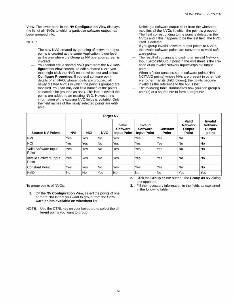
HONEYWELL SPYDER
59
View. The lower pane in the NV Configuration View displays the list of all NVOs to which a particular software output has been grouped into.
NOTE:
— The new NVO created by grouping of software output points is created at the same Application folder level as the one where the Group as NV operation screen is invoked.
— You cannot edit a shared NVO point from the NV Con-figuration View screen. To edit a shared NVO, you must right-click the NVO on the wiresheet and select Configure Properties. If you edit software point details of an NVO, whose points are grouped, all newly created NVOs in which the point is grouped are modified. You can only edit field names of the points selected to be grouped as NVO. This is true even if the points are added to an existing NVO. However, no information of the existing NVO fields is editable. Only the field names of the newly selected points are edit-able.
— Deleting a software output point from the wiresheet modifies all the NVOs in which the point is grouped. The field corresponding to the point is deleted in the NVOs and if this happens to be the last field, the NVO itself is deleted.
— If you group invalid software output points to NVOs, the invalid software points are converted to valid soft-ware points.
— The result of copying and pasting an invalid Network Input/Setpoint/Output point in the wiresheet is the cre-ation of an invalid Network Input/Setpoint/Output point.
— When a folder contains some software points(NVI/NCI/NVO points) whose NVs are present in other fold-ers (other than its child folders), the points become invalid as the reference to the NV is lost.
— The following table summarizes how you can group a point(s) of a source NV to form a target NV.
To group points of NVOs:
1. On the NV Configuration View, select the points of one or more NVOs that you want to group from the Soft-ware points available on wiresheet list.
NOTE: Use the CTRL key on your keyboard to select the dif-ferent points you want to group.
2. Click the Group as NV button. The Group as NV dialog box appears.
3. Fill the necessary information in the fields as explained in the following table.
Source NV Points
Target NV
NVI NCI NVO
Valid Software
Input Point
Invalid Software
Input PointConstant
Point
Valid Network Output Point
Invalid Network Output point
NVI Yes Yes No Yes Yes Yes No NoNCI Yes Yes No Yes Yes Yes No NoValid Software Input Point
Yes Yes No Yes Yes Yes No No
Invalid Software Input Point
Yes Yes No Yes Yes Yes No No
Constant Point Yes Yes No Yes Yes Yes No NoNVO No No Yes No No No Yes Yes

HONEYWELL SPYDER
60
4. Click OK. The new NVO is created and appears in the NVs list in the NV Configuration View. If you select Add to an existing NV, the fields are added to the existing NVO and can be seen in the NVs list.
Edit Network VariablesYou can partially modify Fixed Dropable NVs and totally modify Custom NVs. However, you cannot modify Mandatory and Fixed NVs.
NOTE: If you delete a point of an NV and if this point is the only point in that NV, the NV itself is deleted.
The following table summarizes what you can or cannot do with NVs in the Wiresheet and the NV Configuration Views.
Name DefinitionGroup as New NV
Select this option if you want to save the points you want to group as a new NVO. In this case, you can enter a new NVO Name.
NOTE: The new NVO is created on the same folder on which the NV Config-uration View is invoked. Example: If you have a ControlProgram which has an Application2 residing in Application1, if you group points on the NV Configuration View of Application2, the new NVO is created in the Application2 folder. However, if you grouped NVs on the NV Config-uration View of the Application1, the new NVO is created in the Application1 folder.
Add to Existing NV
Select this option if you want to add the points you want to group to an existing NVO. In this case, you can select an existing custom NVO from the NV Name list.On selecting this option, the original fields of the NVO to which the new points will be added are listed in the Fields Properties table.
NOTE: In the case where the selected NVO was of a SNVT type, the NV is con-verted to a UNVT after grouping of points is done.
NV Name The name that you can configure this NV with.NV Type The NVO type you want to save the selected
points for grouping as.Fields Properties
Displays the following properties for each field:— Field Name — Data Category— Network Data Type— Internal Data Type
Up Arrow Use this button to reorder a field and move it up in the list.
Down Arrow Use this button to reorder a field and move it down in the list.
Point Name The name of the point. It is in the format NVName_PointName.
Field Name User defined field name.Data Category
Select the data type for the NV fields.
Network Data Type
It is the engineering unit received by the Honeywell Spyder controller. This is non-editable.
Internal Data Type
It is the unit(s) of the output of the Network Variable. This is non-editable.
UNVT Name Enter UNVT Name in case you are creating a new NVO.

HONEYWELL SPYDER
61
To edit an NV:
1. Browse to Station > Config > Drivers > LonNetwork > LonSpyder.
2. Select ControlProgram > Views > NV Configuration View. The summary page appears with a list of pre-pro-grammed Mandatory, Fixed, and Custom NVs and Soft-ware points.
3. Select the Fixed/Custom NV you want to edit and click the Edit NV button.
4. The Edit NV: NV Name dialog box appears. If the selected NV is a Fixed Dropable NV type, you can only change the Internal Data Type and click OK to save the changes.
5. If the NV is a Custom type, by default, the settings are such that you can change:
— Internal Data Type— Fail Detect— SNVT Select— Standard/User Defined NV
6. Click OK to save the changes. However, for a Custom NV, you can uncheck the Copy NV From check box and change all parameters as described in Adding an NVI/NCI/NVO, and Many to one NV sections of this doc-ument.
Example: The nciSetPoints is an NV used in the Temperature Set Point Calculator. You can only change its Internal Data Type and the Value.
The following table summarizes editing network variables from the Wiresheet and NV Configuration Views.
TypeShow NV on Wiresheet Create Edit Delete
Wiresheet NV Config View
Wiresheet NV Config View
Wiresheet NV Config View
Wiresheet NV Config View
NVI NCI NVO
Yes.Any NV added to the wiresheet is automatically displayed on the wiresheet
Yes. You need to add an NV and select the points you want to be displayed on the wiresheet by clicking the Display on Wiresheet button.
Yes.You can only add an NV with a single point.
Yes.You can add an NV with multiple points.
Yes.You can only edit an NV with a single point at a time.
Yes.You can edit an NV with multiple points at a time.
Yes.You can only delete an NV with a single point at a time.• NVs of
Fixed Dropable type and NVs with Bit Configuration are not deleted but only hidden from the wiresheet. They are still available in the NVs list.
Yes.You can delete an NV with multiple points at a time.
Many to One
Yes.Any NV added to the wiresheet is automatically displayed on the wiresheet
Yes. You need to add an NV and select the points you want to be displayed on the wiresheet by clicking the Display on Wiresheet button.
No. Yes.You can add an NV with multiple points.
No. Yes.You can edit an NV with multiple points at a time.
Yes.You can only delete an NV with a single point at a time.
Yes.You can delete an NV with multiple points at a time.

HONEYWELL SPYDER
62
NV Type Action From ProcedureNVI/NCI/NVO Remove points from
wiresheetWiresheet You cannot remove (hide) a point from the
wiresheet.Remove points from wiresheet
NV Configuration View 1. Select the exposed fields from the Soft-ware Points available on wiresheet list.
2. Click Remove Points from wiresheet.3. Click OK to confirm.
Edit NV Wiresheet You can only edit individual points of an NV at a time.
1. Right click the individual point of an NV and select Configure Properties.
2. Edit the available fields and click OK to save the changes.
Edit NV NV Configuration View You can edit multiple points of an NV at a time.1. Select the NV from the NVs list on the
right side of your screen on top.2. Click Edit NV and edit one or multiple
points of the NV at once. 3. Click OK to save the changes made.
Delete NV Wiresheet You can only delete individual points of an NV at a time.
Delete NV NV Configuration View You can delete an NV with multiple points at a time. To delete an NV with multiple points:
1. Select the NV from the NVs list on the right side of your screen on top.
2. Click Delete NV. 3. Click OK to save the changes made.
You can also delete individual points in an NV1. Select the NV from the NVs list on the
right side of your screen on top.2. Click Delete NV. 3. Click OK to save the changes made.
Many to One NV Remove points from wiresheet
Wiresheet You can remove (hide) a point from the wiresheet.
1. Select the point of a Many to One NV you want to hide and press Delete button on your keyboard. The point is removed from the wiresheet.
This point is however available in the NVs list in the NV configuration View.
Remove points from wiresheet
NV Configuration View 1. Select the exposed fields from the Soft-ware Points available on wiresheet list and click Remove Points from wiresheet.
2. Click OK to confirm.

HONEYWELL SPYDER
63
NOTE:
— For special NVs used in function blocks, you can only change the Internal Data Type and the Value. All other fields are unusable. Also, you cannot use the name nciSetPoints to name any other item as it is a reserved name.
— If you edit software point details of an NVO, whose points are grouped (shared), all newly cre-ated/shared NVOs in which the point is grouped (shared) are modified. You can only edit field names of the points selected to be grouped as NVO. This is true even if the points are added to an existing NVO. However, no information of the existing NVO fields is editable. Only the field names of the newly selected points are editable.
— When an NVO is edited such that the details of the field whose exposed point is grouped across multiple NVs are modified, the association of the point with the NV is lost. The point is no longer shared with this NVO. The lower pane in the NV Configuration View does not list this NVO in the list of NVOs to which that point belongs. The mod-ified field becomes local to the NVO and you r must explicitly expose it on the wiresheet to use it in the logic
Deleting NVsTo delete an NV:
1. Browse to Station > Config > Drivers > LonNetwork > LonSpyder.
2. Select ControlProgram > Views > NV Configuration View. The summary page appears with a list of pre-pro-grammed Mandatory, Fixed, and Custom NVs and Soft-ware points.
3. Select the Custom NV you want to delete.4. Click the Delete NV button. A Delete Confirmation dia-
log box appears.5. Select:
Retain Points to delete the NV and make its exposed points (if any) as invalid points. Delete Points to delete the NV and its exposed points (if any). Cancel Delete to cancel the deletion
NOTE: While deleting an NV, if you select the Retain Points option, points of the NV are converted to invalid points. The option to retain exposed points of deleted NVs is available only from the NV Configuration View. The invalid points are displayed in the lower pane of the NV Configuration View.
Deleting Software Points From WiresheetIf you delete a software point on the wiresheet, the NV to which the point belonged to is modified such that the corresponding field is deleted. The NV itself is deleted if the field happens to be the last field.
NOTE: In the following cases, deleting a point from the wiresheet puts the point back in the NV.
— If the point is attached to Many to One NVI or Fixed NV
— if the point is configured as Bit Field— if the point is attached to nciTempSetpoints
Invalid PointsYou can delete an NV without deleting its exposed points. Points of such NVs are converted as invalid points. This option is available only from the NV Configuration view.
Edit NV Wiresheet You can only edit individual points of an NV at a time.
1. Right click the individual point of an NV and select Configure Properties.
2. Edit the available fields and click OK to save the changes.
Edit NV NV Configuration View You can edit multiple points of an NV at a time.1. Select the NV from the NVs list on the
right side of your screen on top.2. Click Edit NV and edit one or multiple
points of the NV at once. 3. Click OK to save the changes made.
Delete NV Wiresheet You cannot delete points of a Many to One NV from the wiresheet.
Delete NV NV Configuration View You can delete an NV with multiple points at a time. To delete an NV with multiple points:
1. Select the NV from the NVs list on the right side of your screen on top.
2. Click Delete NV. 3. Click OK to save the changes made.
You can also delete individual points in an NV1. Select the NV from the NVs list on the
right side of your screen on top.2. Click Delete NV. 3. Click OK to save the changes made.
HONEYWELL SPYDER
64
You can copy and paste NVs from a source controller to a target controller. When an application folder containing points, but the NV to which it belongs is present in the parent folder of the folder in which the points are present, is copied/cut and pasted to the target controller, the points become invalid.
When an application folder containing NVs whose points are exposed in its parent folder, is cut/copied and pasted to a target controller, the corresponding field (to which the exposed point belonged) is removed from the NV. The NV is deleted if the point happens to be the last field in the controller.
When an application folder containing NVs (containing bit field configuration) whose points are exposed in its parent folder, is cut/copied and pasted to a target controller, the corresponding field (to which the exposed point belonged) is removed from the NV. However, an additional field is added to the NV to make the NV valid.
NOTE:
— The tool shall allow grouping of invalid software output points to NVOs.
— When the invalid points shall be grouped to form NVs, the invalid points shall be converted to valid software points.
— When an invalid Network Input/Setpoint/Output point is copied and pasted, the resulting point is an invalid point.
— When a folder containing some software points (NVI/NCI points) whose NVs are present in other folders (other than its child folders) is deleted, the NV itself is deleted if the point happens to be the last field of the NV

HONEYWELL SPYDER
65
BACNET OBJECTSAn Object is a data item such as a temperature, a switch value or actuator state. Objects can be thought of as point parameters.
There are three categories of Objects that the Bacnet Spyder supports. They are:
• Mandatory: Mandatory Objects are the default Objects present compulsorily in a Bacnet Spyder device.
• Fixed: Fixed Dropable Objects can be used while creating an application logic and edit only its Internal Data Type can be edited. Fixed Dropable Objects can also be displayed on the wiresheet.
• Custom: Custom Objects are the objects that are created while creating an application logic. They can be created, edited, and deleted based on your requirements.
The following is a list of fixed objects supported by Spyder.
The following is a list of mandatory objects supported by Spyder.
NOTE: The Bacnet Spyder supports the following object types.
— AVI - Analog Value Input — AVO - Analog Value Output — AV Setpoint - Analog Value Setpoint — BVI - Binary Value Input — BVO - Binary Value Output — BV Setpoint - BinaryValue Setpoint
Object Name Object TypeDebugIndex0 Analog-valueDebugIndex1 Analog-valueDebugIndex2 Analog-valueDebugIndex3 Analog-valueDebugIndex4 Analog-valueDebugIndex5 Analog-valueDebugIndex6 Analog-valueDebugIndex6 Analog-valueDebugIndex7 Analog-valueDebugIndex8 Analog-valueDebugIndex9 Analog-valueDebugIndex10 Analog-valueDebugIndex11 Analog-valueDebugIndex12 Analog-valueDebugIndex13 Analog-valueDebug0 Analog-valueDebug1 Analog-valueDebug2 Analog-valueDebug3 Analog-valueDebug4 Analog-valueDebug5 Analog-valueDebug6 Analog-valueDebug7 Analog-valueDebug8 Analog-valueDebug9 Analog-valueDebug10 Analog-valueDebug11 Analog-valueDebug12 Analog-valueDebug13 Analog-value
Object Name Object TypeObject
InstanceHardwareID Analog-value 0BrandModel Analog-value 1VersionReflash Analog-value 2VersionMajor Analog-value 3VersionMinor Analog-value 4InUse Analog-value 5Error0 Analog-value 6Error1 Analog-value 7Error2 Analog-value 8Error3 Analog-value 9Error4 Analog-value 10Error5 Analog-value 11Error6 Analog-value 12Error7 Analog-value 13Error8 Analog-value 14Error9 Analog-value 15Error10 Analog-value 16Error11 Analog-value 17Error12 Analog-value 18Error13 Analog-value 19Error14 Analog-value 20Error15 Analog-value 21AlrmStatus Analog-value 22AlarmH Analog-value 23ConfigErrorID Analog-value 24ConfigErrorNature Analog-value 25ConfigErrorRecord Analog-value 26WMCommErrorDeviceAddr Analog-value 27WMCommErrorFileID Analog-value 28UniqueID0 Analog-value 29UniqueID1 Analog-value 30UniqueID2 Analog-value 31UniqueID3 Analog-value 32UniqueID4 Analog-value 33UniqueID5 Analog-value 34

HONEYWELL SPYDER
66
— MVI - Multi-state Value Input — MVO - Multi-state Value Output — MV Setpoint - Multi-state Value Setpoint
The configured objects are mapped to the Function Block memory space to be used by any Function Block. Each Object is configured with a name.
Viewing the List of Bacnet Objects1. Browse to Station > Config > Drivers > BacnetNet-
work > BacnetSpyder. 2. Select ControlProgram> Views > Object Configura-
tion View. The summary page appears with a list of pre-programmed Mandatory, Fixed, and Custom Objects in a tabular format. The table has the following columns:
— Name: The name of the Object. — Type: Indicates if the object is of type AVI, AVO, AV
Setpoint, BVI, BVO, BV Setpoint, MVI, MVO, or MV Setpoint.
— Category: Indicates if the Object is Mandatory, Fixed, or Custom.
— Object Container: Indicates where the Object is used. — Object Instance: A unique number that is automati-
cally assigned to the object. — Update Rate: The polling rate to update object value
of Object components. — Send Heartbeat: The rate at which output objects
send data to network. 3. The bottom half of the Object Configuration view dis-
plays the physical and software points available on the wiresheet in a tabular format. The table has the follow-ing columns:
— Point Name: The name of the physical /software point as it appears on the wiresheet.
— Field Names: Indicates the Object type. — Point Container: Indicates where the physical /soft-
ware point is used. All physical /software points that are used in a Program within an application are also listed.
NOTE:
— Mandatory Objects cannot be used in the applica-tion logic.
— Mandatory Objects cannot be edited or deleted.— In a Fixed Dropable Object, only Internal Data
Type can be modified.— Custom Object is the user defined Object. A Cus-
tom Object can be edited or deleted.— Fixed Objects marked as Fixed_Dropable can be
exposed on the wiresheet. Other fixed objects cannot be exposed as points.
— When a user changes the device model, if the name of a custom object clashes with a fixed object name in the target model, Honeywell Spy-der generates a new unique name for the custom object and creates the new fixed object.
Object InputThe Object Inputs (Analog Value Input, Binary Value Input, Multi-state Value Input) convert a raw object input into a value(s) that can be used by other function blocks.
When an Object Input is added to the wiresheet, the object appears in the Object Configuration View.
Adding an Object InputYou can add an Object Input from:
1. Object Configuration View 2. HoneywellSpyder Palette
Adding an Object Input from the Object Configuration ViewTo add a new Object Input:
1. Browse to Station > Config > Drivers > BacnetNet-work > BacnetSpyder.
2. Select ControlProgram > Views > Object Configura-tion View. The summary page appears with a list of pre-programmed Mandatory, Fixed, and Custom Objects.
NOTE: If adding an Object Input to an application, browse through to the appropriate application on the Nav palette.
3. Click Add Object. The New Object dialog box appears. Select an Object Type (Analog Value, Binary Value, Multi-state Value).
NOTE: The Input option is selected by default under Select Point Type.
4. Click OK. The Advanced (Network Input) dialog box appears.
5. Fill the necessary information in the fields and click OK to complete adding an Object Input. The Object Input is displayed in the Objects table.
NOTE: You cannot add an Object Input to a macro. You can only add a Software point with Point Type as Constant to a macro. You cannot add a Network Output to a macro.
Exposing an Object Input from the Object Configuration ViewTo expose the Object Inputs you have added:
1. Select the object you want to display on the wiresheet from the objects table and click the Show on wiresheet as Points button. or Drag the object you want to display on the wiresheet on to the Software Points available on wiresheet list at the bottom of the Object Configuration View. The Add Points dialog box appears.
2. Click OK. The object you have selected appears on the Software Points available on wiresheet list at the bot-tom of the view. The field name displays the Object Name. Field Name information. If you do not select point to be displayed on the wiresheet, the Object is added but is not visible on the wiresheet.

HONEYWELL SPYDER
67
3. Click Cancel if you do not wish to continue adding an Object Input.
Adding an Object Input From Spyder PaletteWhile in the midst of creating an ControlProgram/Application, if you need to quickly add an Object Input, use the Network Input item on the Spyder Palette.
NOTE: You cannot add an Object Input to a macro. You can only add a Software point with Point Type as Con-stant to a macro.
To add an Object Input to an ControlProgram/Application:
1. On the Spyder Palette, expand the SoftwarePoints folder. If the Spyder Palette is not visible on the left side of your screen, on the Menu bar, click Windows > Sidebars > Palette to display the Palette.
2. Drag a Network Input to the wiresheet of an Control-Program/Application. The Name dialog box appears.
3. Type a name for the point and click OK.
4. Right-click the Network Input point you have just added and select Configure Properties. The Configure Properties dialog box appears.
5. Select Network Input, Modulating Input, or Binary Input from the Point Type field.
6. Type or select the following: — Point Name: Type a name for the point. — Point Category: Select a category. — Unit : Select the unit for the Point Category chosen. — Sub-Category: Select the enumeration type. — Value: This is disabled.
7. Click the Advanced button. The Advanced(Network Input) dialog box appears.
8. Fill the necessary information in the fields and click OK to return to the configure properties dialog box.
9. Click OK to complete adding an Object Input.
Connecting Object InputsOnce you have created an Object Input, you can connect an Object Input to an Object Output/Function Block or Physical point by left-clicking on the output of an Object Input and dragging your mouse to the input of an Object Output/Function Block or Physical point.
Object SetpointThe Object Setpoints are Analog Value Setpoint, Binary Value Setpoint and Multi-State Value Setpoint.
Adding an Object SetpointYou can add an NCI from:
1. Object Configuration View 2. HoneywellSpyder Palette
Adding an Object Setpoint from the Object Configuration ViewTo add a new Object Setpoint:
1. Browse to Station > Config > Drivers > BacnetNet-work > BacnetSpyder.
2. Select ControlProgram > Views > Object Configura-tion View. The summary page appears with a list of pre-programmed Mandatory, Fixed, and Custom Objects.
NOTE: If adding an Object Setpoint to an Application, browse through to the appropriate Application on the Nav palette.
3. Click Add Object. The New Object dialog box appears. Select an Object Type (Analog Value, Binary Value, Multi-state Value).
4. Select the Select Point Type as Setpoint. 5. Click OK. The Advanced(Network Input) dialog box
appears. 6. Fill the necessary information in the fields and click OK
to complete adding an Object Setpoint. The Object Set-point is displayed in the Objects table.
NOTE: You cannot add an Object Setpoint to a macro. You can only add a Object Input with Point Type as Con-stant to a macro.
Name DefinitionObject Name The name of the Object Input. This
field is editable.Object Type Indicates if the object input is of type
AV, BV or MSV. This field is non-editable.
Object Instance A unique number that is automatically assigned to the object. This field is editable. If you try replacing the instance value with a value of your choice, the replacement is successful only if the value of your choice is not in use by any other object.
Update Interval The rate at which the input object is updated.
Object Category Displays the unit of measurement for the object input.
Unit Displays the engineering unit based on the object category.
Sub-Category Displays the enumeration type for the object inputs. The field Unit is renamed as Sub-Category if the object category selection is unitless.
Fail Detect Enabled Set the Fail Detect Enabled of each object input to either True or False. • True means if the Object Input is
bound and it has not received an update from the Bacnet network source in the fail detect time then an alarm is generated and the Object Input is set to Invalid.
• False means the Object Input retains what was written to it until a Bacnet network source changes it or the Honeywell Spyder has a power outage or resets.
Update Rate The polling rate to update Object values of Object components.

HONEYWELL SPYDER
68
Exposing an Object Setpoint from the Object Configuration ViewTo expose the Object Setpoints you have added:
1. Select the object you want to display on the wiresheet from the objects table and click the Show on wiresheet as Points button. or Drag the object you want to display on the wiresheet on to the Software Points available on wiresheet list at the bottom of the Object Configuration View. The Add Points dialog box appears.
2. Click OK. The object you have selected appears on the Software Points available on wiresheet list at the bot-tom of the view. The field name displays the Object Name. Field Name information. If you do not select point to be displayed on the wiresheet, the Object is added but is not visible on the wiresheet.
3. Click Cancel if you do not wish to continue adding an Object Setpoint.
Adding an Object Setpoint from the Spyder PaletteWhile in the midst of creating an ControlProgram/Application, if you need to quickly add an Object Setpoint, use the Network Setpoint item on the Spyder Palette.
NOTE: You cannot add an Object Setpoint to a macro. You can only add a Software point with Point Type as Constant to a macro. You cannot add a Object Out-put to a macro.
To add an Object Input to an ControlProgram/Application:
1. On the Spyder Palette, expand the SoftwarePoints folder.
NOTE: If the Spyder Palette is not visible on the left side of your screen, on the Menu bar, click Windows > Sidebars > Palette to display the Spyder Palette.
2. Drag a Network Setpoint to the wiresheet of an Con-trolProgram/Application. The Name dialog box appears.
3. Type a name for the point and click OK. 4. Right-click the Network Setpoint point you have just
added and select Configure Properties. The Config-ure Properties dialog box appears.
5. By default Network Setpoint is the Point Type. If it is not, select Network Point from the Point Type field.
6. Type or select the following: — Point Name: Type a name for the point. — Point Category: Select a category. — Unit: Select the unit for the Point Category chosen. — Sub-Category: Select the enumeration type. — Value: Enter a value based on the Point Category
and Units fields chosen. 7. Click OK to complete adding an Object Setpoint.
Connecting Object SetpointsOnce you have created an Object Setpoint, you can connect a point of an Object Setpoint to an Object Output/Function Block or Physical point by left-clicking on the output of an Object Setpoint and dragging your mouse to the input of an Object Output/Function Block or Physical point.
Object OutputThe Object Outputs (AVO, BVO, MVO) convert input value(s) (Public Variable(s)) into a raw network variable output that is published onto the Bacnet network.
Adding an Object OutputYou can add an Object Output from:
1. Object Configuration View 2. HoneywellSpyder Palette
Adding an Object Output from the Object Configuration ViewTo add a new Object Output:
1. Browse to Station > Config > Drivers > BacnetNet-work > BacnetSpyder.
2. Select ControlProgram > Views > Object Configura-tion View. The summary page appears with a list of pre-programmed Mandatory, Fixed, and Custom Objects.
NOTE: If adding an Object Output to an Application, browse through to the appropriate Application on the Nav palette.
3. Click Add Object. The New Object dialog box appears. 4. Select an Object Type (Analog Value, Binary Value,
Multi-state Value). 5. Select the Select Point Type as Setpoint. 6. Click OK. The Advanced (Network Output) dialog box
appears.
Name DefinitionObject Name The name of the Object Setpoint.
This field is editable.Object Type Indicates if the object input is of type
AV, BV or MSV. This field is non-editable.
Object Instance A unique number that is automatically assigned to the object. This field is editable. If you try replacing the instance value with a value of your choice, the replacement is successful only if the value of your choice is not in use by any other object.
Update Interval The rate at which the setpoint object is updated.
Object Category Displays the unit of measurement for the object setpoint.
Unit Displays the engineering unit based on the object category.
Sub-Category Displays the enumeration type for the object inputs. The field Unit is renamed as Sub-Category if the object category selection is unitless.

HONEYWELL SPYDER
69
7. Fill the necessary information in the fields and click OK to complete adding an Object Output. The Object Out-put is displayed in the Objects table.
NOTE: You cannot add an Object Output to a macro.
Exposing an Object Output from the Object Configuration ViewTo expose the Object Output you have added:
1. Select the object you want to display on the wiresheet from the objects table and click the Show on wiresheet as Points button. or Drag the object you want to display on the wiresheet on to the Software Points available on wiresheet list at the bottom of the Object Configuration View. The Add Points dialog box appears.
2. Click OK. The object you have selected appears on the Software Points available on wiresheet list at the bot-tom of the view. The field name displays the Object Name. Field Name information. If you do not select point to be displayed on the wiresheet, the Object is added but is not visible on the wiresheet.
3. Click Cancel if you do not wish to continue adding an Object Output.
Adding an Object Output from the Spyder PaletteWhile in the midst of creating an ControlProgram/Application, if you need to quickly add an Object Output, use the Network Outputs item on the Spyder Palette.
NOTE: You cannot add an Object Output to a macro.
To add an Object Output to an ControlProgram/Application:
1. On the Spyder Palette, expand the SoftwarePoints folder. If the Spyder Palette is not visible on the left side of your screen, on the Menu bar, click Windows > Sidebars > Palette to display the Palette.
2. Drag a Network Output to the wiresheet of an Control-Program/Application. The Name dialog box appears.
3. Type a name for the point and click OK. 4. Right-click the Network Output point you have just
added and select Configure Properties. The Config-ure Properties dialog box appears.
5. Select Network Output, Modulating Output, or Binary Output from the Point Type field.
6. Type or select the following: — Point Name: Type a name for the point. — Point Category: Select a category. — Unit : Select the unit for the Point Category chosen. — Sub-Category: Select the enumeration type.
7. Click OK to complete adding an Object Output.
Connecting Object OutputsOnce you have created an Object Output, you can connect an Object Output to an Object Input/Function Block or Physical point by left-clicking on the output of an Object Input/Function Block/Physical point and dragging your mouse to the input of an Object Output.
Edit ObjectsYou can partially modify Fixed Dropable Objects and totally modify Custom Objects. However, you cannot modify Mandatory and Fixed Objects.
NOTE: If you delete a point of an Object and if this point is the only point in that Object, the Object itself is deleted.
Name DefinitionObject Name The name of the Object Output. This
field is editable.Object type Indicates if the object input is of type
AV, BV or MSV. This field is non-editable.
Object Instance A unique number that is automatically assigned to the object. This field is editable. If you try replacing the instance value with a value of your choice, the replacement is successful only if the value of your choice is not in use by any other object.
Update Interval The rate at which the output object is updated.
Sen Delta The Significant Event Notification is also known as SEN Delta. The object is sent on the Bacnet Network whenever any field exceeds the SEN Delta. SEN Delta of zero (0) disables the feature.
Object Category Displays the unit of measurement for the object output.
Unit Displays the engineering unit based on the object category.
Sub-Category Displays the enumeration type for the object inputs. The field Unit is renamed as Sub-Category if the object category selection is unitless.
GPU Set the GPU of each object output to either True or False.• True means if the Object Output is
bound and it has not sent an update to the Bacnet network target in the GPU specified time then an alarm is generated and the Object Output is set to Invalid.
• False means the Object Output retains what was written to it until a Bacnet network source changes it or the Honeywell Spyder has a power outage or resets.
Send Heart Beat The rate at which output objects send data to the network.

HONEYWELL SPYDER
70
The following table summarizes what you can or cannot do with Objects in the Wiresheet and the Object Configuration View.
To edit an Object:
1. Browse to Station > Config > Drivers > BacnetNet-work > BacnetSpyder.
2. Select ControlProgram > Views > Object Configura-tion View. The summary page appears with a list of pre-programmed Mandatory, Fixed, and Custom Objects and Software points.
3. Select the Fixed or Custom Object you want to edit and click the Edit Object button.
4. The Edit Object Name dialog box appears. If the selected Bacnet object is a Fixed Dropable Object type, you can only change the Internal Data Type and click OK to save the changes.
5. If the object is Custom type, by default, the settings are such that you can change:
— Object Name — Object Type — Object Instance — Update Interval
6. Click OK to save the changes.
TypeShow Object on wiresheet Create Edit DeleteWiresheet Object Config
ViewWiresheet Object
Config ViewWiresheet Object
Config ViewWiresheet Object
Config View
Object InputObject SetpointObject Output
Yes.Any Object added directly to the wiresheet is automatically displayed on the wiresheet
Yes. You need to add an Object and select the points you want to be displayed on the wiresheet by clicking the Display on Wiresheet button.
Yes.You can add an object with a single point.
Yes.You can add an object with single point.
Yes.You can edit an Object with a single point at a time.
Yes.You can edit an Object with single point at a time.
Yes.You can delete an Object with a single point at a time.Objects of Fixed Dropable type and Objects with Bit Configuration are not deleted but only hidden from the wiresheet. They are still available in the Objects list.
Yes.You can delete an Object with single point at a time.

HONEYWELL SPYDER
71
The following table summarizes editing bacnet objects from the Wiresheet and NV Configuration View.
Deleting ObjectsTo delete an Object:
1. Browse to Station > Config > Drivers > BacnetNet-work > BacnetSpyder.
2. Select ControlProgram > Views > Object Configura-tion View. The summary page appears with a list of pre-programmed Mandatory, Fixed, and Custom objects and Software points.
3. Select the Custom object you want to delete. 4. Click the Delete Object button. A Delete Confirmation
dialog box appears. 5. Select:
— Retain Point(s) to delete the object and make its exposed points (if any) as invalid points.
— Delete Point(s) to delete the object and its exposed points (if any).
— Cancel to cancel the deletion.
NOTE: While deleting an object, if you select the Retain Point(s) option, point of the object is converted to invalid point. The option to retain exposed points of deleted objects is available only from the Object Configuration View. The invalid points are dis-played in the lower pane of the Object Configura-tion View.
Object Type Action From ProcedureObject Input/
ObjectSetpoint./ObjectOutput
Remove points from wiresheet Wiresheet You cannot remove (hide) a point from the wiresheet.
Remove points from wiresheet Object Configuration View 1. Select the exposed fields from the Points available on wiresheet list.
2. Click Remove Points from wiresheet.
3. Click OK to confirm. Edit Object Wiresheet 1. You can edit individual
points of an object at a time.
2. Right-click the individual point of an object and select Configure Prop-erties.
3. Edit the available fields and click OK to save the changes.
Edit Object Object Configuration View 1. You can edit individual points of an object at a time.
2. Select the object from the Objects list on the right side of your screen on top.
3. Click Edit Object and edit the point of the object.
4. Click OK to save the changes made.
Delete Object Wiresheet 1. You can delete individual points of an objects at a time.
Delete Object Object Configuration View 1. You can delete an object with individual points at a time. To delete an object with individual points:
2. Select the object from the Objects list on the right side of your screen on top.
3. Click Delete Object. 4. Click OK to save the
changes made.
HONEYWELL SPYDER
72
Deleting Points From WiresheetIf you delete a software point on the wiresheet, the object to which the point belonged to is modified such that the corresponding field is deleted. The object along with it's point is deleted.
Invalid PointsYou can delete an Object without deleting its exposed points. Points of such Objects are converted to invalid points. This option is available only from the Object Configuration View.
You can copy and paste objects from a source controller to a target controller. When an application folder containing points, but the object to which it belongs is present in the parent folder of the folder in which the points are present, is copied or cut and pasted to the target controller, the points become invalid.
When an application folder containing objects whose points are exposed in its parent folder, is cut or copied and pasted to a target controller, the corresponding field (to which the exposed point belonged) is removed from the object. The object is deleted if the point happens to be the last field in the controller.
When an application folder containing objects (containing bit field configuration) whose points are exposed in its parent folder, is cut or copied and pasted to a target controller, the corresponding field (to which the exposed point belonged) is removed from the object. However, an additional field is added to the object to make the object valid.
NOTE: When an invalid object input, setpoint, or an output point is copied and pasted, the resulting point are also invalid.

HONEYWELL SPYDER
73
BINDINGS OR DATA SHARINGA binding refers to a configured association between LonWorks network variables (NVs) either within a device, or between separate devices on a Lon network.
Data Sharing is the terminology that is used for Bindings in case of Bacnet devices.
Binding Lon Devices To bind two Lon Devices in Honeywell Spyder Tool:
1. Right-click Lon Network in the Nav palette and select Views > Wire sheet. All devices on the Lon Network are displayed as containers on the wire sheet.
2. Right-click the source device container and select Link Mark.
3. Right-click the target device container and select Link from Source Device Name. The Link dialog box appears.
4. Click the NV of the source controller you want to link. The pane showing the target NVs highlights NVs with which you can bind the source NV.
5. Select the NV from the target device pane to which you want to link the source NV.
6. Click OK. A link appears on the wire sheet between the source and target controllers.
7. Right click Lon Network in the Nav palette and select Views > Link Manager. A row providing the link details appears.
8. Select the row and click Bind to complete binding NVs between a source and target controller.
When you perform the operations such as, add/delete/modify NVs in Control Program, the changes are not reflected to NVs under LonSpyder device until you perform a download operation or click Generate NVs.
Generate NVs option recreates the NVs under the device as per the NVs in the Control Program of that device. You do not have to be online for the Spyder device to use this option. You can set up offline Lon bindings involving Spyder devices and bind the devices when the Spyder devices are online. This feature is useful for offline engineering.
Binding Bacnet DevicesTo bind two Bacnet devices in Honeywell SpyderTool:
1. Right-click Bacnet Network in the Nav palette and select Views > Wiresheet. All devices on the Bacnet Network are displayed as containers on the wiresheet.
2. Right-click the source device container and select Link Mark.
3. Right-click the destination device container and select Link To. The Link dialog box appears.
4. Click the Object of the source controller you want to link. The pane showing the destination objects highlights the objects with which you can bind the source object.
5. Select the Object from the destination device pane to which you want to link the source object.
NOTE: The Object Properties of the source device shows Present Value. This implies that the present value of the object input or object out-put is taken as input to the control logic. The Object Properties of the destination device shows Present Value for all objects except AO and BO. When an AO or BO object is selected as a destination object, Object Properties dis-plays the priority array index from 1 to 16. You can set the priority value for the destination object. If an AO and BO object is set as the source objects, then their present value is taken as input to drive the logic.
6. Click OK. A link appears on the wiresheet between the source and destination controllers.
7. Right-click Bacnet Network in the Nav palette and select Views > Bacnet Link Manager. A row providing the link details appears.
8. Select the row and click Bind to complete binding Objects between a source and destination controller.
NOTE: Binding cannot be done if both source and destina-tion devices are third party Bacnet devices. Atleast one of them must be a Spyder device.
— AI, BI, AV/BV/MSV(setup as NetworkOutput) can act as source objects to the device.
— AV/BV/MSV (setup as NetworkInput) can act as destination objects to the device.
— Only the custom Bacnet objects are displayed in the Link dialog box for binding devices. The man-datory and fixed objects are not available for bind-ing.
When you perform the operations such as, add/delete/modify Network Objects in Control Program, the changes are not reflected to BacnetObjectReferences under BacnetSpyder device until you click on Generate Network Objects.
Generate Network Objects option recreates the BacnetObjectReferences under the device as per the Bacnet Objects under Control Program of that device. You do not have to be online for the Spyder device to use this option. You can set up offline Bacnet data sharing links involving Spyder devices and bind the devices when the Spyder devices are online. This feature is of useful for offline engineering.
About Bacnet Link ManagerUsing Bacnet Link Manager view, you can manage the binding of Spyder devices. The view also provides the link details of the Bacnet devices.
The following link details are displayed in the Bacnet Link Manager view.
• Link Status: Displays the current status of each link as NewLink, Bound, or Obsolete. For more details, see “Types of Link Status”.

HONEYWELL SPYDER
74
• Device Status: Displays the status of the device as synch, Out-of-synch, or offline. If the device status is synchronized, it indicates that the binding are downloaded to the controller. Out-of-synch indicates that the download is pending. If the device status is offline, it indicates that the device is not downloaded to the controller.
• Source Device: Displays the name of the source Bacnet device whose output is linked or bound to the destination Bacnet device.
• Source Object: Displays the name of the Bacnet object in the source device.
• Source Property: Displays the object property of the source object.
• Destination Device: Displays the name of the destination Bacnet device.
• Destination Object: Displays the name of the Bacnet object in the destination device.
• Destination Property: Displays the object property of the destination object. The object property of the destination device shows PresentValue for all objects, except AO and BO. When an AO or BO object is selected as a destination object, destination property displays the priority selected.
• Poll or Push: Spyder Bacnet devices use a poll/push mechanism to share data on the network. Every Spyder Bacnet device has 1 poll table and 1 push table, the size of each being 256. The tool automatically decides the poll/push mechanism when you add a link. The push table on the source Spyder is filled first and when there are no spare entries in the push table, the poll table on the destination device is used. When there is binding between a Spyder and a third party device, the push/poll table on the Spyder device is used depending on whether it is a source or a target device. The status Poll implies that the target device would poll the value periodically from the source device used in binding. The interval for polling is the Update Rate configured on the destination object. The status Push implies that the source device would push the value periodically to the target device. The interval for pushing the data is the GPU interval configured on the source object. You cannot select the mechanism to be used for binding.
Opening Bacnet Link Manager ViewTo access the Bacnet Link Manager view:
• Right-click Bacnet Network in the Nav tree and select View > Bacnet Link Manager.
Bacnet Link Manager CommandsThe following commands are available in the Bacnet Link Manager view-
Add
• Click Add ,to bind two Spyder Bacnet devices, or bind a Spyder Bacnet device and a third party Bacnet device.
Delete
• Click Delete, to delete the links from the database. The link status changes to Obselete after the deletion, to indicate that the link is deleted only in the database. Click Bind, to remove the binding information from the controller.
Refresh
• Click Refresh, to refresh the status of the bindings between the devices. The link status is displayed as NewLink, Bound, or Obsolete, depending on whether the link is downloaded to the device or is yet to be downloaded.
Bind
• Click Bind, to download the binding information to the devices. The link status is updated, after the Bind option is invoked.
Selective Bind
• Click Selective Bind, to download the binding information selectively to one or more devices.
Learn Link(s)
• Click Learn Link(s), to learn the binding information from the devices. The link status is updated, after the binding information is retrieved from the device. On clicking Learn Link(s), all obsolete links are marked as Bound. The NewLinks that are not yet downloaded to the controller are retained.
NOTE:
— At any point, for Learn Link(s) to restore the link status from a Spyder Bacnet device, the device has to be in downloaded state, that is, the applica-tion in Control Program of the source device in Niagara should match that in the online device. Otherwise Learn Links(s) does not learn links from that device.
— The application in the target device involved in data sharing in Niagara does not have to match that in the online device.
Clear Bindings
• Click Clear Bindings, to clear all the links from the device. The links that are in Bound and Obsolete states are marked as NewLink.
Types of Link StatusEach link or binding in the Bacnet Link Manager view appears with a status in the LinkStatus column. The links show one of the following status, assuming there is no error.
— NewLink: If links are created between two or more devices and are not downloaded to the device.
— Bound: If links are created between two or more devices and are downloaded to the device. On clicking the Bind button on the Bacnet Link Manager view, all the links with a status as NewLink are converted to Bound.
— Obsolete: If links that are downloaded to the device are deleted. All links with a status as Bound are changed to Obsolete when you click the Delete but-ton on the Bacnet Link Manager view. On clicking the Bind button on the Bacnet Link Manager view, all links with a status as Obsolete are deleted.
Error ConditionsErrors and warnings may occur while attempting to change or modify data when the devices are bound. The following are some of the error conditions.

HONEYWELL SPYDER
75
— After the devices are bound, a break in communication between the devices causes a Network Communica-tion alarm, which is displayed in the Error View.
— If the GPU rate of the source or target device is changed after the links are downloaded to the device, then a warning message appears suggesting you to download the links once again to the device. In the Bacnet Link Manager view, the links with the status as Bound are changed to NewLink.
— If the GPU rate on the source is greater than the update rate on the target, a warning message appears.
— When changing a point type results in the change of the Bacnet object type, a warning message appears to delete the links. It may not be possible to bind the new object type with the existing objects.
— When editing Bacnet objects from the Object Config-uration View, the links with status as Bound is changed to NewLink.
— If the source and target devices are third party devices, an error message appears.
Add BindingsAdd Bindings allows you to bind two devices wherein at least one device is a Spyder device. You can bind two devices in any one of the following ways.
— A Spyder source device with a Spyder destination device
— A Spyder source device with a third party destination — A third party source device with a Spyder destination
device
The Spyder device can be selected under the Source Details or the Destination Details section.
Perform the following to bind two Spyder devices.
1. Select a Spyder Bacnet source device from the Device list.
2. Select the source object from the Object list. 3. Select presentValue from the Property list. 4. Select a Spyder Bacnet destination device from the
Device list. 5. Select the destination object from the Object list. 6. Select presentValue from the Property list when the
destination object type is AV, BV, and MSV. or Select the priority value from the Property list when the destination object type is AO or BO. A priority value from 1 to 16 can be set for the destination object.
NOTE: The priority index selected for binding in case of a destination device should be different from the priority index being driven by the control-program logic.
7. Click OK to bind the two devices.
Perform the following to bind a Spyder source device with a third party destination device.
1. Select a Spyder source device from the Device list. 2. Select the source object from the Object list.
3. Select presentValue from the Property list. 4. Select a third party destination device from the Device
list. 5. Select the destination Object Type from the list. 6. Type the object instance number in the Object ID text
box. A default Object Name is provided for the destina-tion object.
NOTE: The Object Name can be edited.
7. Select presentValue from the Property list when the destination object type is AV, BV, and MSV. or Select the priority value from the Property list when the destination object type is AO or BO. A priority value from 1 to 16 can be set for the destination object.
8. Click OK to bind the two devices.
Perform the following to bind a third party source device with a Spyder destination device.
1. Select a third party source device from the Device list. 2. Select an Object Type from the list. 3. Type the object instance number in the Object ID text
box. A default Object Name is provided for the destina-tion object.
NOTE: The Object Name can be edited.
4. Select presentValue from the Property list. The present value of the source object is taken by default.
5. Select a Spyder Bacnet destination device from the Device list.
6. Select the destination object from the Object list. 7. Select presentValue from the Property list when the
destination object type is AV, BV, and MSV. or Select the priority value from the Property list when the destination object type is AO or BO. A priority value from 1 to 16 can be set for the destination object.
NOTE: The priority index selected for binding in case of a destination device should be different from the priority index being driven by the control program logic.
8. Click OK to bind the two devices.
NOTE: Binding cannot be done if both source and destina-tion devices are third party Bacnet devices. An error message, "Cannot create the link. Both are non-bindable devices." appears, if you try binding two third party devices.
Binding Jace and SpyderA Jace can behave as a Bacnet device. Points from Spyder and other third party devices can be exported to the Jace to be monitored. The points in the Jace are monitored by setting up a binding between the Jace and Spyder. This reduces the number of polls needed to read or write values to the point.
Configuring Bacnet DeviceThe Local Device represents the Bacnet device being added to the network.

HONEYWELL SPYDER
76
1. Expand Config > BacnetNetwork > Bacnet Comm > Network in the Nav sidebar.
2. Right-click MstpPort and choose Actions > Enable. The Property Sheet on the right pane displays the details of the mstp port. The details include Network Number and Mstp Address.
3. Drag a Bacnet device from the Palette onto the Nav sidebar. For more details, see "Adding a Controller" under "Get-ting Started".
4. Type a name for the device you are adding and click OK.
5. Right-click the Bacnet device in the Nav sidebar and choose Views > Property Sheet.
6. Type the Network Number specified in the Network Number text box of the Mstp Port.
7. Type the MAC Address specified in the Mstp Address text box of the Mstp Port.
8. Set MAC Address Style as MSTP/Other.
See "About BACnet server access" on the Niagara Help set for more details on monitoring points by binding JACE and Spyder controller.
By default, the Bacnet driver provides read access to all exposed objects from third party Bacnet devices.
To enable write access to exposed objects from third party Bacnet devices, you must ensure that you have the necessary permissions to those objects. To allow write access, the Super User option must be enabled in the Property Sheet of the user service.
See "About BACnet server access" on the Niagara Help set for more details on allowing write access from Bacnet.
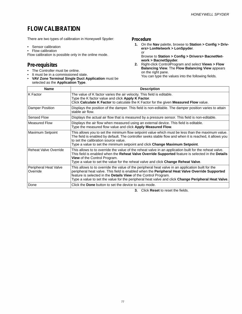
HONEYWELL SPYDER
77
FLOW CALIBRATIONThere are two types of calibration in Honeywell Spyder:
• Sensor calibration• Flow calibrationFlow calibration is possible only in the online mode.
Pre-requisites • The Controller must be online. • It must be in a commissioned state. • VAV Zone Terminal Single Duct Application must be
selected as the Application Type.
Procedure 1. On the Nav palette, browse to Station > Config > Driv-
ers> LonNetwork > LonSpyder. or Browse to Station > Config > Drivers> BacnetNet-work > BacnetSpyder.
2. Right-click ControlProgram and select Views > Flow Balancing View. The Flow Balancing View appears on the right pane. You can type the values into the following fields.
3. Click Reset to reset the fields.
Name DescriptionK Factor The value of K factor varies the air velocity. This field is editable.
Type the K factor value and click Apply K Factor. Click Calculate K Factor to calculate the K Factor for the given Measured Flow value.
Damper Position Displays the position of the damper. This field is non-editable. The damper position varies to attain stable air flow.
Sensed Flow Displays the actual air flow that is measured by a pressure sensor. This field is non-editable.Measured Flow Displays the air flow when measured using an external device. This field is editable.
Type the measured flow value and click Apply Measured Flow.Maximum Setpoint This allows you to set the minimum flow setpoint value which must be less than the maximum value.
The field is enabled by default. The controller seeks stable flow and when it is reached, it allows you to set the calibration source value.Type a value to set the minimum setpoint and click Change Maximum Setpoint.
Reheat Valve Override This allows to to override the value of the reheat valve in an application built for the reheat valve. This field is enabled when the Reheat Valve Override Supported feature is selected in the Details View of the Control Program.Type a value to set the value for the reheat valve and click Change Reheat Valve.
Peripheral Heat Valve Override
This allows to to override the value of the peripheral heat valve in an application built for the peripheral heat valve. This field is enabled when the Peripheral Heat Valve Override Supported feature is selected in the Details View of the Control Program.Type a value to set the value for the peripheral heat valve and click Change Peripheral Heat Valve.
Done Click the Done button to set the device to auto mode.

HONEYWELL SPYDER
78
The following is a list of NVs/NCIs that must be present:
OR
The following is a list of Bacnet Objects that must be present:
NvName Data TypenviFlowOverride snvt_hvac_overidnciMaxFlowSetPt snvt_flownciOccMinFlowSetPt snvt_flownciKFactor snvt_count_inc_fnciDuctArea snvt_area nciMeasMinFlow snvt_flownciMeasMaxFlow snvt_flownvoBoxFlow snvt_flownvoCmdCoolDmpPos snvt_lev_percentnvoVelSenPress SNVT_press_pnvoPressOffset SNVT_press_p
NvName Data TypenciKFactor snvt_count_inc_fnciDuctArea snvt_areanciMaxFlowSetpt snvt_flownciMinFlowSetpt snvt_flownciBalanceSetPts / BoxZeroOffset snvt_press_fnciBalanceSetPts / KFactorOffset snvt_count_inc_fnciBalanceSetPts / MaxMeasFlowAct snvt_flownciBalanceSetPts / MaxMeasFlowSpt snvt_flownciBalanceSetPts / MinMeasFlowAct snvt_flownciBalanceSetPts / MinMeasFlowSpt snvt_flownviFlowOverride snvt_hvac_overidnciApplVerNew/typeOfAppl[0] UBYTEnciApplVerNew/typeOfAppl[1] UBYTEnvoBoxFlow snvt_flownvoVelSenPress snvt_press_fnvoDamperPos snvt_lev_percentnviValveOvrd / reheatPos snvt_lev_percentnviValveOvrd / periphPos snvt_lev_percent
Object Type Data TypeCfgKFactor (AV) VAL-floatCfgDuctArea (AV) square footCfgMaxFlowSetpt (AV) cfmCfgMinFlowSetpt (AV) cfmBalBoxZeroOffset (AV) pascalBalKFactorOffset (AV) VAL-float

HONEYWELL SPYDER
79
BalMaxMeasFlowAct (AV) cfmBalMaxMeasFlowSpt (AV) cfmBalMinMeasFlowAct (AV) cfmBalMinMeasFlowSpt (AV) cfmFlowOvrdState (AV) VAL-ubyteFlowOvrdPct (AV) PercentFlowOvrdFlow (AV) cfmTypeOf App (AV) VAL-ubyteAppFeatures (AV) VAL-ubyteBoxFlow (AV) cfmVelSenPress (AV) inches of waterDamperPos (AV) PercentOvrReheatPos (AV) PercentOvrPeriphPos (AV) Percent

HONEYWELL SPYDER
80
FUNCTION BLOCKSUse Function Blocks to program the Honeywell Spyder controller to perform a wide variety of HVAC applications. Function Blocks are modules that perform a specific task by reading inputs, operating on them, and outputting a value(s). Use the Programming Tool to select the appropriate function blocks, configure them and connect them together to perform a specific HVAC application.
Function Blocks are classified into six categories. They are:
• Analog Function Blocks • Logic Function Blocks • Math Function Blocks • Control Function Blocks • Zone Control Function Blocks • Data Function Blocks
Add DeviceTo add a device:
1. Select HoneywellSpyder from the drop-down list in the Spyder Palette.
2. Drag the LonSpyder folder on to LonNetwork in the Nav tree. or Drag the BacnetSpyder folder on to BacnetNetwork in the Nav tree
3. Enter the desired name for the device and click OK.
Add Function BlockTo add a function block:
1. Display the Spyder palette (If you do not see the Spyder palette on the left pane, on the Menu bar select Win-dow > Side Bars > Palette). The Spyder palette is dis-played with the following items:
— Physical Points: Modulating and Binary Inputs/Out-puts.
— SoftwarePoints: Constant/Network Input/Setpoint/Output. Use this to create NVI, NCI, NVO, or con-stants.
— Analog: Analog function blocks— Logic: Logic function blocks— Math: Math function blocks— Control: Control function blocks— DataFunction: Data Function function blocks— ZoneArbitration: Zone Arbitration function blocks— BuiltIn: BuiltIn function blocks— Macro: A Macro is a group of functional blocks
grouped together that define a specific functionality. Commonly used program elements can be defined as macros so that they could be reused across applica-tions.
— Program: This includes macros and logic that you can define and use in applications.
— StandardApplications: Standard applications shipped by Honeywell which you can use to build application logic
2. Expand the LonSpyder or BacnetSpyder device in the Nav tree and select the ControlProgram folder.
3. Drag and drop the desired function block on to the wiresheet.
4. Enter the name of the function block and click OK. The function block is added and appears on the wire sheet.
NOTE: A total of 100 function blocks are supported in the LonSpyder I, Spyder II, and Bacnet Spyder mod-els.Spyder Micro models support 200 Function blocks.
— LonSpyder I models are: PVL6436A, PVL6438N, and PUL6438
— LonSpyder II models are: PVL 6436AS, PVL 6438NS, and PUL 6438S
— LonSpyder Micro models are: PVL4024NS, PVL4022AS, PUL4024S, PUL1012S, and PVL0000AS
— BacnetSpyder models are: PVLB6436AS, PVB 6438NS, and PULB6438S
Configure Function BlockComplete the following procedure to configure a function block:
1. Add the desired function block to the wiresheet of an Application Logic, Program or Macro. See Adding a Device and Adding a Function Block for more details.
2. Right-click the function block on the wiresheet and select Configure Properties. A dialog box with the con-figuration details appears.
3. Enter information in the available fields. 4. Click Apply to save the changes
or Click OK to save the changes and close the dialog box.
5. Click Cancel to revert to the last saved settings and close the dialog box.
Delete Function BlockTo delete a function block:
1. On the wiresheet, select the function block you want to delete.
2. Click the Delete button on your keyboard or right-click the function block and select Delete. The function block is deleted along with bindings to it, if any.
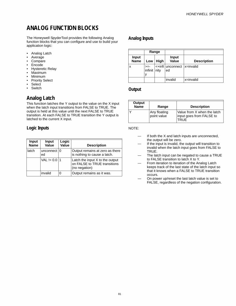
HONEYWELL SPYDER
81
ANALOG FUNCTION BLOCKSThe Honeywell SpyderTool provides the following Analog function blocks that you can configure and use to build your application logic:
• Analog Latch• Average• Compare• Encode• Hysteretic Relay• Maximum• Minimum• Priority Select• Select• Switch
Analog LatchThis function latches the Y output to the value on the X input when the latch input transitions from FALSE to TRUE. The output is held at this value until the next FALSE to TRUE transition. At each FALSE to TRUE transition the Y output is latched to the current X input.
Logic Inputs
Analog Inputs
Output
NOTE:
— If both the X and latch inputs are unconnected, the output will be zero.
— If the input is invalid, the output will transition to invalid when the latch input goes from FALSE to TRUE.
— The latch input can be negated to cause a TRUE to FALSE transition to latch X to Y.
— From iteration to iteration of the Analog Latch keeps track of the last state of the latch input so that it knows when a FALSE to TRUE transition occurs.
— On power up/reset the last latch value is set to FALSE, regardless of the negation configuration.
Input Name
Input Value
Logic Value Description
latch unconnected
0 Output remains at zero as there is nothing to cause a latch.
VAL != 0.0 1 Latch the input X to the output on FALSE to TRUE transitions (no negation)
invalid 0 Output remains as it was.
RangeInput Name Low High
Input Value Description
x >=-infinity
<+infinity
unconnected
x=invalid
invalid x=invalid
Output Name Range Description
Y Any floating point value
Value from X when the latch input goes from FALSE to TRUE

HONEYWELL SPYDER
82
Example
An illustration to explain the behavior of the Analog Latch.

HONEYWELL SPYDER
83
AverageThis function calculates the average of 8 inputs. You can have a combination of analog inputs from other function blocks and constant values as inputs to this function block. The output is set to the average of the connected inputs.
NOTE: The Output returns an invalid value if no inputs are connected or if all inputs are invalid.
Ignore invalid inputs: Select this option if you want the function block to ignore any invalid inputs, if any, and consider only the valid inputs to calculate the output. If this option is left unselected, the invalid inputs will make the output also as invalid. This option is not supported in the PVL6436A, PVL6438N, or PUL6438 models and therefore you cannot download this configuration to those models.
NOTE: This option is not supported in the Lon models PVL6436A, PVL6438N, or PUL6438 and therefore you cannot download this configuration to those models.
Inputs
Outputs
RangeInput Name Low High Input Value Description
in1-8 >=- infinity <+ infinity unconnected not used in calculationif all inputs unconnected then output = invalid
in1-8 >=- infinity <+ infinity invalid If any input is invalid then output=invalid
Output Name Range DescriptionOUTPUT Any floating point number Average of the inputs

HONEYWELL SPYDER
84
CompareThis function compares two inputs to each other.
NOTE: It is possible to create invalid numbers by combining large values of input 2 and on and off hysteresis. The behavior is dependant on the operation selected, value of input 1, and the compiler. (That is, the simu-lator may have a behavior different from the product.)
The following comparison calculations can be made using the Compare function block:
— Input1 less than input2— Input1 greater than input2— Input1 equal to input2
Additionally, on and off hysteresis analog inputs are provided which you can use to make compare calculations.
NOTE: The Output returns a zero value if no inputs are con-nected or if all inputs are invalid.
Inputs
Setpoints
Outputs
RangeInput Name Low High
Input Value Description
input1-2 >=- infinity
<+ infinity
unconnected
out = 0
invalid out = 0onHyst 0 unconnect
edval = 0
invalid val = 0offHyst 0 unconnect
edval = 0
invalid val = 0
NameRange Value Description
Operation Equals • The output is set to true if (Input 2 – On Hyst) <= input 1 <= (Input 2 + Off Hyst)
Less Than
• The output is set to true if Input 1 < (input 2 – on Hyst)
• The output does not change if (Input 2 – on Hyst) <= input1 less than (Input 2 +off Hyst)
• The output is set to false if Input1 >= (Input 2 + off Hyst)
Greater Than
• The output is set to true if Input 1 > (input 2 + on Hyst)
• The output does not change if (Input 2 – off Hyst) < input1 <= (Input 2 + on Hyst)
• The output is set to false if Input1 <= (Input 2 - off Hyst)
Output Name Range Description
OUTPUT False (0) or True (1)
• Comparison of inputs
• If Property Negate is selected, the output is negated after performing the logic. The sense of the hysteresis settings does not change.
• When negation is selected, the old output (from the previous cycle) is determined by negating the current value of the output.

HONEYWELL SPYDER
85
EncodeThis function translates enumerations of a digital value into different enumeration numbers, allowing standard and custom enumerations to be combined and used together. If a match between inEnum and one of the in values is found, then the appropriate output value is put into out and the “fire” line is true. If there is no match, then the inEnum is put to the out and fire is false. Disable disables all matching and allows the inEnum to be put to the out line.
Analog Inputs
NOTE: In123,In456, In789, Out 123,and Out456 are created by taking each individual input value (0-255) and convert to a hex byte (0x00 – 0xFF) and putting first value in Most Significant Byte, 2nd value in middle and 3rd value in Least Significant Byte. The end result gives an integer value that must be stored as a float. So if In1 is 1, In2 is 2 and In3 is 3 then the inte-ger would be 0x010203=66051, and the float value stored as a parameter would be 66051.0. The tool will prompt user for individual in1 out9 values and do the conversion both to and from the packed structure for the user
RangeInput Name Low High Input Value Description
inEnum 0 255 unconnected
Val = 0
invalid Val = 0Val matches an input value
Output = matching input’s output value
Val matches two or more input values
Output = matching input’s first output value
Disable 0 255 unconnected
Val= 0
invalid Val = 0VAL !=0 All mappings
disable, pass input to output
Val=0 Enable mappingsIn 1,2,3 0 167772
15.00xAABBCC See Note
Input 1 value 0xAA maps to output 1 values; Input 2 value 0xBB maps to output 2 Input 3 value 0xCC maps to output 3
In 4,5,6 0 16777215.0
0xDDEEFF See Note
Input 4 value 0xDD maps to output 4 values; Input 5 value 0xEE maps to output 5 Input 6 value 0xFF maps to output 6
In 7,8,9 0 16777215.0
0xGGHHII See Note
Input 7 value 0xGG maps to output 7 values; Input 8 value 0xHH maps to output 8 Input 9 value 0xII maps to output 9
Out 1,2,3 0 16777215.0
0xaabbcc See Note
Input 1 value 0xaa maps to output 1 values; Input 2 value 0xbb maps to output 2 Input 3 value 0xcc maps to output 3
Out 4,5,6 0 16777215.0
0xddeeff See Note
Input 4 value 0xdd maps to output 4 values; Input 5 value 0xee maps to output 5 Input 6 value 0xff maps to output 6
Out 7 0 255 0xgg Input 7 value 0xgg maps to output 7 values;
Out 8 0 255 0xhh Input 8 value 0xhh maps to output 8 values;
Out 9 0 255 0xii Input 9 value 0xii maps to output 9 values;

HONEYWELL SPYDER
86
Analog Outputs
For example, to map a standard HVAC enumeration into a custom enumeration, the standard HVAC enumeration and desired mapping is as follows:
The first encode function block parameters are:
• In 1,2,3 : 0,1,2 = 0x000102 = 258• In 4,5,6: 3,4,5 = 0x030405 = 197637• In 7,8,9: 6,7,8 = 0x060708 = 395016• Out 1,2,3: 0,2,2 = 0x000202 = 514• Out 4,5,6: 0,7,0 = 0x000700 = 1792• Out 7: 255• Out 8: 255• Out 9: 3And the Second block:
• In 1,2,3: 255,0,0 = 0xFF0000 = 16711680• In 4,5,6: 0,0,0 = 0x000000 = 0• In 7,8,9: 0,0,0 = 0• Out 1,2,3: 1,0,0 = 0x010000 = 65535• Out 4,5,6: 0,0,0 = 0• Out 7: 0• Out 8: 0• Out 9: 0Connect as follows:
RangeInput Name Cfg Low High
Input Value Description
Out OUT_DIG
0 255 See description
If input matches a block mapping and disable is false, then output = block mapping. If input does not mach a block mapping or if disable is true, the output = input.
fire OUT_DIG
0 1 See description
If disable is false and input matches a block mapping then fire is true. If disable is true then fire is true.
In Param
eter
Input EnumerationsCfg
Out Parameter
#Output
Enumerationsin1 HVAC
_AUTO
0 out1 COOL_MODE 0
in2 HVAC_HEAT
1 out2 HEAT_MODE 2
in3 HVAC_MORNING_WARM_UP
2 out3 HEAT_MODE 2
in4 HVAC_COOL
3 out4 COOL_MODE 0
in5 HVAC_NIGHT_PURGE
4 out5 NIGHT_MODE 7
in6 HVAC_PRECOOL
5 out6 COOL_MODE 0
in7 HVAC_OFF
6 out7 OFF_MODE 255
in8 HVAC_TEST
7 out8 OFF_MODE 255
in9 HVAC_EMERGENCY_HEAT
8 out9 EMERG_HEAT 3
Block 2 passed through
HVAC_FAN_ONLY
9 Block2 not used
Pass through (output =9) (Does not require mapping because the output is the same as the input.)
Block2In1
HVAC_NUL
255 Block2Out1 REHEAT_MODE
1

HONEYWELL SPYDER
87
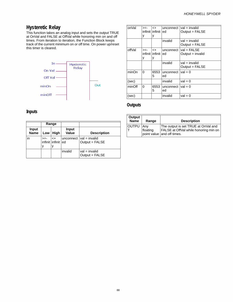
HONEYWELL SPYDER
88
Hysteretic RelayThis function takes an analog input and sets the output TRUE at OnVal and FALSE at OffVal while honoring min on and off times. From iteration to iteration, the Function Block keeps track of the current minimum on or off time. On power up/reset this timer is cleared.
InputsOutputs
RangeInput Name Low High
Input Value Description
in >=- infinity
<+ infinity
unconnected
val = invalidOutput = FALSE
invalid val = invalidOutput = FALSE
onVal >=- infinity
<+ infinity
unconnected
val = invalidOutput = FALSE
invalid val = invalidOutput = FALSE
offVal >=- infinity
<+ infinity
unconnected
val = FALSEOutput = invalid
invalid val = invalidOutput = FALSE
minOn 0 65535
unconnected
val = 0
(sec) invalid val = 0minOff 0 6553
5unconnected
val = 0
(sec) invalid val = 0
Output Name Range Description
OUTPUT
Any floating point value
The output is set TRUE at OnVal and FALSE at OffVal while honoring min on and off times.

HONEYWELL SPYDER
89
MaximumThis function calculates the maximum of 8 inputs (connected inputs or inputs set as constant). The output is set to the largest input.
NOTE: If one or more inputs are selected as constant, any previous connection from outputs of other functional blocks to this block is removed automatically and the maximum of the selected constant values is set as the output.
Ignore invalid inputs: Select this option if you want the function block to ignore any invalid inputs, if any, and consider only the valid inputs to calculate the output. If this option is left
unselected, the invalid inputs will make the output also as invalid. This option is not supported in the PVL6436A, PVL6438N, or PUL6438 models and therefore you cannot download this configuration to those models.
Inputs
Outputs
RangeInput Name Low High
Input Value Description
in1-8 >=- infinity
<+ infinity
unconnected
Not used in calculation.If all inputs are unconnected, output is invalid.
in1-8 >=- infinity
<+ infinity
invalid If any input is invalid then output is invalid
in1-8 >=- infinity
<+ infinity
valid Calculates the maximum of 8 inputs or those set as constant.
Output Name Range Description
OUTPUT
Any floating point number
Maximum of the inputs

HONEYWELL SPYDER
90
MinimumThis function calculates the minimum of 8 inputs or those set as constant. The output is set to the smallest input. Unused/invalid inputs are ignored.
Ignore invalid inputs: Select this option if you want the function block to ignore any invalid inputs, if any, and consider only the valid inputs to calculate the output. If this option is left unselected, the invalid inputs will make the output also as invalid. This option is not supported in the PVL6436A, PVL6438N, or PUL6438 models and therefore you cannot download this configuration to those models.
Inputs
Outputs
RangeInput Name Low High
Input Value Description
in1-8 >=- infinity
<+ infinity
unconnected
Not used in calculation.If all inputs are unconnected, output is invalid.
in1-8 >=- infinity
<+ infinity
invalid If any input is invalid then output is invalid
in1-8 >=- infinity
<+ infinity
valid Calculates the maximum of 8 inputs or those set as constant.
Output Name Range Description
OUTPUT
Any floating point number
Maximum of the inputs

HONEYWELL SPYDER
91
Priority SelectThis function allows one to four inputs in any combination to be individually enabled to override the default. The output is the input with its highest priority enabled TRUE.
Login Inputs
Analog Inputs
Setpoint
Output
Based on the In1asDefault option and the Enable options selected, the output is set as Input as follows:
Input Name
Input Value
Logic Value Description
enable1-4
VAL != 0.0 1
0 0unconnected
0
invalid 0
RangeInput Name Low High
Input Value Description
in1-4 >=- infinity
<+ infinity
unconnected
val = invalid
invalid val = invalid
Name Range/Value DescriptionIn1AsDefault
Yes Output is set to Input 1 even if all Enable Inputs 1-4 are invalid
No Output is set to Invalid if all Enable Inputs 1-4 are disabled.
Output Name Range Description
OUTPUT
Any floating point value The output is set to the input that is enabled.
• If all inputs are unconnected, output is invalid
• If all Enable inputs are disabled, and all inputs are invalid, output is invalid
• If SetIn1asDefault is enabled, output is Input1, even if all Enable inputs are disabled.
• When SetIn1asDefault is disabled/Enabled and if at least one Enable input is enabled, output is the input with its highest priority enabled TRUE. The priority order among Enable inputs is:
1. Enable1 2. Enable2 3. Enable3 4. Enable4
In1asDefault Enable Inputs 1-4 Inputs 1-4 Output

HONEYWELL SPYDER
92
Enabled Disabled Output is set to Input1Enabled Output is set to highest enabled input.
Disabled Disabled Output is invalidOne or more inputs is Enabled
Output is set to one of the Inputs 1-4 based on the priority order:
1. Enable1 2. Enable2 3. Enable3 4. Enable4
NOTE:
• Enable 1 has highest priority and if it is enabled, output is taken as Input1.
• If Enable 1 is disabled, Enable 2 has the next highest priority and if Enable 2 is enabled, output is taken as Input 2.
• Enable 3 has the third highest priority and if Enable 1 and Enable 2 are disabled, output is taken as Input 3.
• Enable 4 has the least priority and output is set to Input 4 only if Enable 1-3 are disabled.

HONEYWELL SPYDER
93
SelectThe Select function block selects one of the 6 input values to be transferred to the output. The input selected depends on the values of x and the offset.
The default input allows multiple Select function blocks to be tied together by chaining the output of one block to the default input of the next. When Select function blocks are chained, all chained blocks receive the same input, but different offsets, so they examine different ranges of the input value. When (x-offset) selects one of the 6 inputs, the output equals the value on input (x-offset). Otherwise, the output equals the value on the default input.
Analog Inputs
Output
Setpoint
NOTE: If any input is invalid, the output is invalid.
Output = Position determined by the value (X - Offset). If the value of (X – Offset) is greater than 6, the default value is taken as the Output.
If the value (X - Offset) is a floating point number between 0 and 6, the position is determined thus:
• 0.10 – 0.99, 0 is returned and Input 0 is taken as Output• 1.10 – 1.99, 1 is returned and Input 1 is taken as Output • 2.10 – 2.99, 1 is returned and Input 2 is taken as Output• 3.10 – 3.99, 1 is returned and Input 3 is taken as Output• 4.10 – 4.99, 1 is returned and Input 4 is taken as Output• 5.10 – 5.99, 1 is returned and Input 5 is taken as OutputExample 1:
X = 100, Offset = 97, default = 10
Output = 100 – 97 = 3, and hence Input 3 is taken as the output.
Example 2:
X = 100.6, Offset = 95.2, default = 10
Output = 100.6 – 95.2 = 5.4, and hence Input 5 is taken as the output.
Example 3:
X = 100, Offset = 5.2, default = 10
Output = 100 – 5.2 = 94.4, and hence default value 10, is taken as the output.
In1asDefault
Enable Inputs
1-4 Inputs 1-4 OutputEnabled Disable
dOutput is set to Input1
Enabled Output is set to highest enabled input.
Disabled Disabled
Output is invalid
One or more inputs is Enabled
Output is set to one of the Inputs 1-4 based on the priority order:Enable1 Enable2 Enable3 Enable4Note:Enable 1 has highest priority and if it is enabled, output is taken as Input1.If Enable 1 is disabled, Enable 2 has the next highest priority and if Enable 2 is enabled, output is taken as Input 2.Enable 3 has the third highest priority and if Enable 1 and Enable 2 are disabled, output is taken as Input 3.Enable 4 has the least priority and output is set to Input 4 only if Enable 1-3 are disabled.
Output Name Range Description
Output Any floating point value
Output = input (x-offset)
Name Range Descriptionoffset 0 - 255 Used to determine the
output as Output = input (x-offset)

HONEYWELL SPYDER
94
SwitchThis function takes an enumerated type input and subtracts a user defined offset to determine which output to set TRUE, holding all others FALSE. The valid range of the input minus the offset is 0 through 7.
The output X (0 through 7) is TRUE if input – offset = X, else, it is FALSE.
Analog Inputs
Output
Setpoint
Output = Output position determined by the value (input - Offset). If the value of (input – Offset) is greater than 7, all outputs are taken as FALSE.
If the value (input - Offset) is a floating point number between 0 and 8, the position is determined thus:
• 0.10 – 0.99, 0 is returned, Output 0 is TRUE and all other outputs are FALSE
• 1.10 – 1.99, 1 is returned, Output 1 is TRUE and all other outputs are FALSE
• 2.10 – 2.99, 2 is returned, Output 2 is TRUE and all other outputs are FALSE
• 3.10 – 3.99, 3 is returned, Output 3 is TRUE and all other outputs are FALSE
• 4.10 – 4.99, 4 is returned, Output 4 is TRUE and all other outputs are FALSE
• 5.10 – 5.99, 5 is returned, Output 5 is TRUE and all other outputs are FALSE
• 6.10 – 6.99, 6 is returned, Output 6 is TRUE and all other outputs are FALSE
• 7.10 – 7.99, 7 is returned, Output 7 is TRUE and all other outputs are FALSE
Example 1:
Input = 100, Offset = 97
Output = 100 – 97 = 3, and hence Output 3 is made TRUE and all other outputs are made FALSE.
Example 2:
X = 100.6, Offset = 95.2
Output = 100.6 – 95.2 = 5.4, and hence Output 5 made TRUE and all other outputs are made FALSE.
Example 3:
X = 100, Offset = 5.2
Output = 100 – 5.2 = 94.4, and hence all Outputs are made FALSE.
RangeInput Name
Low
High
Input Value Description
input 0 255 unconnected
val = invalid, all outputs off.
invalid val = invalid, all outputs off.in - offset > 7
all outputs off.
in - offset < 0
all outputs off.
Output Name Range Description
OUTPUT 0-7
Any floating point value
The output 0 through 7 is TRUE if (input – offset) = X, otherwise it is FALSEIf you negate an output, the output is negated from the value determined by the function block logic.
Output Name
Range/Value Description
offset 0 - 255 Used to determine which Output is set to TRUE based on the expression (input - offset) = Output

HONEYWELL SPYDER
95
BUILT IN FUNCTION BLOCKSThe Honeywell SpyderTool provides the following Built In function blocks that you can configure and use to build your application logic:
• Schedule• Wall Module
— Conventional wall module— SBus wall module
ScheduleThe Schedule function block configures schedule and schedule assignment for the controller. The day and date is used by the scheduler to determine the scheduled occupancy. The time of day and date may be updated by an external device via LON communications. This function calculates the current occupancy state, next state and time until next state (TUNCOS) based on the date/time and the schedule.
InputsDate and Time from the operating system are the inputs to the Scheduler.
OutputsSchedule Current State is the occupancy state the controller must be in at this minute.
• OCC means use the occupied set point.• UNOCC means use the unoccupied set point.• STANDBY means use the standby set point.• Schedule Next State is the occupancy state the controller
will go to after the current state is complete. • OCC means the next state is occupied.• UNOCC means the next state is unoccupied.• STANDBY means the next state is standby.• OCCNUL means the next state is unknown.• Schedule TUNCOS is the time (in minutes) until the next
change of state. The Honeywell Spyder controller uses this to perform setpoint recovery.
Configure SchedulesYou can configure occupancy schedules for eight days of the week: Monday through Sunday, and a holiday. There are four events per day with one state/time per event. There are four states:
• Occupied• Standby• Unoccupied• Unconfigured
The event time range is 0 - 1439 minutes. The event time resolution is 1 minute. Zero is the first minute of the day at 12:00 a.m. 1439 is the last minute of the day at 11:59 p.m. Event times greater than 1439 minutes are illegal and the event is treated as if the state were null.
The scheduled events execute in the order based on time of day. It is not necessary for the events to be in time sequential order. If the events are entered non-sequentially, the event which is the earliest is executed and the next earliest and so on. If an event state is not programmed (Unconfigured), the event time can be anything and will not be used.
To configure a schedule:
1. On the Scheduling tab, click the day of the week to select the day you want to configure the schedule.
2. Select a maximum of four events, Occ1, Occ2, Unocc1, Unocc2, for the selected day. Use the drop down list to specify occupancy status for the event. Notice that the cell turns green if the occupied mode is selected, white for an unoccupied mode, yellow for a standby mode and windows default background color for the unconfigured option.
3. Click the hours, minutes, and/or AM/PM and use the up/down arrow buttons to set the time.
4. Click Apply Event.5. Repeat the steps 1 through 5 for the remaining days of
the week and the Holiday.To unconfigure a day schedule/event:
1. Select the row/cell of the day whose schedule you want to unconfigure.
2. Right-click the row/cell and select Delete. The schedule for that row/cell is unconfigured.
To copy the schedule from one day/event to another:
1. Select the day/event by right-clicking the time line row.2. Select Copy.3. Right-click the destination row and select Paste.
Configure Holiday SchedulesYou can schedule a maximum of 10 holidays. Each scheduled holiday has a valid start month, day, and duration. Holidays are every year by definition. After the start month/date is calculated, the duration is added to find the end date. If it is a one day holiday, then the duration is one day. The end date is set to the start date. If the current date is within the start and end dates, inclusive, then it is a holiday.
You can specify holidays in any order in the list. Holidays do not have to be in date consecutive order. The Scheduler is called once per second and ensures that the clock time of the day is valid. It computes the occupancy by examining the programmed schedule. It looks at the current date/time and compares it to the entered schedule and holidays to determine the current state, next state and TUNCOS.
A holiday is configured by a start date and duration. The start date can be a specific date or a relative day in a month. A holiday is not specific to a particular year, each holiday configuration is applicable for every year.

HONEYWELL SPYDER
96
A holiday can be configured by either specifying a date or by specifying a day in a month. To configure a Holiday schedule:
1. Click the Holidays tab. You have options to select holi-days based on weekday/month every year or on a spe-cific date every year.
2. To specify a weekday/month for every year as a holiday, select the Weekday/Month for every year option to con-figure a holiday by selecting a weekday in a month. Select the month from the Select Holiday Start Month list and the day from the Select Holiday Start Day list to specify the holiday start month and start day. The days are the relative days, such as, First Sunday, Fourth Monday, and so on.
3. To specify a specific date(s) every year as a holiday, select the Specific Date for every year option to con-figure a holiday by selecting a specific date for every year. Select the month from the Select Holiday Start Month list and the date from the Select Holiday Start Date list to specify the holiday start month and start date.
4. Select the month, start date, and duration of the holiday from the Select Holiday Start Month, Select Holiday Start Date, and Duration fields respectively. The dura-tion can be configured from 1 to 255 days.
5. Select one of the options provided and click Add to add to the Holiday list.
6. To remove a holiday from the Holiday List, select the holiday and click Remove.
Load U.S. HolidaysTo select the list of US holidays to your holiday list, click the Load US Holidays button. The following pre-configured US holidays are loaded to the holiday list:
• January 1• Memorial Day• July 4• Labor Day• Thanksgiving and Day After• Christmas Eve and Day AfterIf there are more than four holidays already configured, the Load US holidays option will not load all the six holidays, since they would exceed the maximum holiday count. The first few US holidays are loaded until the total count has reached the maximum of 10 holidays. No duplicate holidays are allowed.
Save Schedule• Click Apply to save the changes you made to the
schedule.• Click OK to save the changes and close the Schedule
dialog box.• Click Cancel to close the Schedule dialog box without
saving the changes.
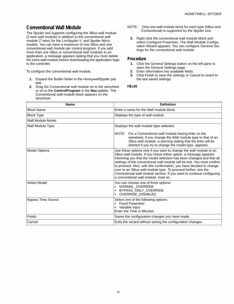
HONEYWELL SPYDER
97
Conventional Wall ModuleThe Spyder tool supports configuring the SBus wall module (2-wire wall module) in addition to the conventional wall module (7-wire) for the LonSpyder II, and Spyder Micro models. You can have a maximum of one SBus and one conventional wall module per control program. If you add more than one SBus or conventional wall modules to an application, a message appears stating that you must delete the extra wall module before downloading the application logic to the controller.
To configure the conventional wall module:
1. Expand the BuiltIn folder in the HoneywellSpyder pal-ette.
2. Drag the Conventional wall module on to the wiresheet or on to the ControlProgram in the Nav palette. The Conventional wall module block appears on the wiresheet.
NOTE: Only one wall module block for each type (SBus and Conventional) is supported by the Spyder tool.
3. Right click the conventional wall module block and select Configure Properties. The Wall Module Configu-ration Wizard appears. You can configure General Set-tings for the conventional wall module.
Procedure1. Click the General Settings button on the left pane to
open the General Settings page. 2. Enter information into available fields. 3. Click Finish to save the settings or Cancel to revert to
the last saved settings.
FIELDS
Name DefinitionBlock Name Enter a name for the Wall module block.Block Type Displays the type of wall module.Wall Module Model Wall Module Type Displays the wall module type selected.
NOTE: For a Conventional wall module having links on the wiresheet, if you change the Wall module type to that of an SBus wall module, a warning stating that the links will be deleted if you try to change the model type, appears.
Model Options Use these options only if you want to change the wall module to an SBus wall module. If you check either option, a message appears informing you that the model selection has been changed and that all settings of the conventional wall module will be lost. You must confirm to proceed. Also, with this confirmation, you have decided to change over to an SBus wall module type. To proceed further, see the Conventional wall module section. If you want to continue configuring a conventional wall module, read on.
Select Model You can choose one of three options:• NORMAL_OVERRIDE • BYPASS_ONLY_OVERRIDE • OVERRIDE_DISABLED
Bypass Time Source Select one of the following options:• Fixed Parameter • Variable Input Enter the Time in Minutes.
Finish Saves the configuration changes you have made.Cancel Exits the wizard without saving the configuration changes.

HONEYWELL SPYDER
98
SBus wall moduleThe Spyder tool supports configuring the SBus (Sensor-Bus) wall module (2-wire wall module) in addition to the conventional wall module for the LonSpyder II, Spyder Enhanced, and Spyder Micro models. You can have a maximum of one SBus and one conventional wall module per control program. Additionally, Bacnet Spyder models also support configuring the SBus wall module.
NOTE: If you add more than one S-Bus or conventional wall modules to an application, the following message appears, stating that you must delete the extra wall module before downloading the application logic to the controller.
However, if you fail to delete the second wall module and click the Validate button on the toolbar, an error message appears.
Click OK to close the message window and delete the extra wall module before downloading the application logic.
You can configure different models of the S-Bus wall modules in one of two ways.
1. You can invoke the configuration wizard of the S-Bus wall module function block and use the wizard screens to configure the wall module. Use the Preview screen to preview the configuration you have made. You must download the configuration changes made to the con-troller to view the configuration changes on the Wall module.
2. You can configure locally using the display screen of the wall module mounted on the wall. This can be done only in the Contractor mode.
After completing the configuration, link the slots on the S-Bus wall module function block of the control program logic of the Spyder tool as required. The input and output slots of the Wall module can be connected to other function blocks, Physical/software points, and NVs/Bacnet objects, to develop the application logic. You can then download the configuration to the controller. This configuration is then automatically downloaded to the S-Bus wall module by the Spyder controller.
If you have made changes to the configuration locally on the wall module, you can upload the same to the controller. Note that the wall module configuration is not uploaded directly to the Spyder tool. So, you need to upload the Spyder controller configuration to the tool in order to upload the wall module configuration.
If you change one of the following and perform a quick download, only the changed configuration is downloaded to the controller.
— Toggling the Viewable by Tenant check box. — Changing the default home screen only. — Changing the default value of Value from wall module. — Changing the default value of Sensor or Offset
parameters. For all other changes, the whole configuration is downloaded (full download) to the controller.
You can save these applications to the Spyder library for later use. Applications that are stored can be imported from the library and used to rapidly build application logic.
You can also delete an already configured S-Bus wall module function block if necessary.
You can:
— Connect the S-Bus wall module to the controller and use the Spyder tool to configure it by using the S-Bus wall module function block in the control program.
— Save the configuration changes you make and down-load it to the controller
— Upload the changes in settings you make on the wall module display to the Spyder controller using the Spy-der tool
— Simulate the S-Bus wall module logic using the Simu-lation feature of the Spyder tool
— Store the S-Bus wall module configuration in the Spy-der library to be reused across applications
Use the Wall Module Configuration Wizard to configure the S-Bus wall module.
Initial Setup and Configuration Once the wall module is wired to the controller, you configure the wall module using the Spyder tool.
CONFIRM BUS ADDRESS SETTING Check to ensure that the bus address dial (located on the back of the module) of the Wall Module is set to one (1) to match the default setting of the configuration tool.
NOTE: Multi-drop installations are not available at this time. Only one wall module may be wired to the program-mable controller.

HONEYWELL SPYDER
99
Configuring S-Bus wall moduleTo configure the S-Bus wall module using the configuration wizard:
1. Expand the BuiltIn folder in the HoneywellSpyder pal-ette.
2. Drag and drop the S-Bus wall module on to the wiresheet or on to the ControlProgram in the Nav pal-ette. The S-Bus wall module block appears on the wiresheet. This block only shows slots relevant to the configuration that you have made. By default, slots con-figured in standard applications will be shown as part of the wall module block.
NOTE: Only one wall module block for each type (S-Bus and Conventional) is supported by the Spyder tool. If you drop more than one block of the same wall module type, the tool gives a warning message and does not allow the addition of the second wall module of the same type.
3. Right click the S-Bus wall module block and select Con-figure Properties. The Wall Module Configuration Wiz-ard appears.
You can configure the following settings using the Wizard and are displayed on the left pane of the wizard:
— General Settings
— Categories and Parameters — Home Screen Options — Occupancy and Override — Fan Command — System Status and Command — Preview
NOTE: When you drag and drop the S-Bus wall module on the wiresheet, right click it, and select Configure Properties, the General Settings properties are dis-played in the Wizard window.
General SettingsUse this page to configure the general settings of the S-Bus wall module.
PROCEDURE1. Click the General Settings button on the left pane to
open the General Settings page. 2. Enter information into available fields. 3. Click Finish to save the settings or Cancel to revert to
the last saved settings. 4. Click Next to display the Categories and Parameters
page.
FIELDS
Name DefinitionBlock Name Enter a name for the Wall module block.Block Type Displays the type of wall module.Wall module modelWall Module Type Lists all wall module models supported by Spyder. The following
options are available:• Temperature Only • Temperature, Humidity • Temperature, CO2 • Temperature, CO2, Humidity Depending on the wall module type selected, the available models are displayed in the Select Model list.The Wall Module type you select determines the function block type. If you select a model of Conventional wall module type, the function block becomes a Conventional wall module. Similarly, if the module type selected is an S-Bus wall module, the function block becomes a S-Bus wall module.
NOTE: For a Conventional wall module having linkages on the wiresheet, if you change the Wall module type to that of an S-Bus wall module, a warning stating that the linkages will be deleted if you try to change the model type appears.

HONEYWELL SPYDER
100
Model Options You have the following model options to choose from:• LCD Display • 2 wire Sensor Bus Communication For the current Spyder version, the available models have both LCD display and 2-wire Sensor Bus Communication options and therefore selecting any one option automatically selects the other.
NOTE: Based on the Wall Module Type and the Model Option selected, the Model Selection list displays the available mod-els.
Changing conventional wall module to S-Bus and vice-versaYou can suitably change the wall module you have dropped on to the wiresheet by checking the Model Options check-boxes. If you have dropped a conventional wall module on the wiresheet and check any of the the Model Options check-boxes, the wall module changes to a S-Bus wall module and all the wizard buttons are displayed on the left pane. Similarly, if you have dropped an S-Bus wall module on the wiresheet and uncheck the Model Options checkbox, the wall module changes to that of a conventional type and all wizard buttons except for the General Settings disappear from the left pane.
Select Model The options available in this list are based on the Wall Module Type and Model Option selected. Example: If you select Temperature Only as the Wall Module Type and LCD Display as the Model option, The Select Model list lists Temp (LCD, 2 Wire) as the selectable option.
Application Selection These fields are available only if a level 3 (TR 70) model is selected. For all other models, these fields are hidden.
Application Type This field appears automatically when a level 3 model is dropped on the wiresheet or if you select a level 3 model from the Wall Module Type list. You can select one of three applications:Standard Application (default): Displays the eight pre programmed application names in the Select Application List. Custom Application: Displays existing custom applications in the Select Application List. New Application: This selection hides the Application Selection list and displays all the wizard menu items along the left side of the window.

HONEYWELL SPYDER
101
Select Application Select from one of the eight pre programmed applications:• VAV- Min/Max Balance, Network Override: Typical set-up for a VAV
system pre-configured with a Min/ Max Airflow balancing method (balancing can be done through the wall module keypad), and uses the network determined occupied override duration.
• VAV- K-Factor Balance, Network Override: Typical set-up for a VAV system pre-configured with a KFactor method of balancing (balancing can be done though the wall module keypad), and uses the network determined occupied override duration.
• VAV- No Balance, Network Override: Typical set-up for a VAV system. No balancing loaded, which frees up additional memory if greater controller parameter access is desired. Uses the network determined occupied override duration.
• VAV- No Balance, Full Override: Typical set-up for a VAV system. No balancing loaded, which frees up additional memory if greater controller parameter access is desired. Loaded with a user adjustable occupied override time from 30 minutes to 3 hours, as well as an adjustable vacation (multiple day) override (unoccupied), and a continuous unoccupied time.
• FCU- Network Override: Typical set-up for a fan coil system pre-configured to use the network determined occupied override duration.
• FCU- Full Override: Typical set-up for a fan coil system pre-configured to use the network determined occupied override duration. Loaded with a user adjustable occupied override time from 30 minutes to 3 hours, as well as an adjustable vacation (multiple day) override (unoccupied), and a continuous unoccupied time.
• CVAHU- Network Override: Typical set-up for a CVAHU system pre-configured to show system status and system override (heat, cool, auto, etc., like a thermostat), and uses the network determined occupied override duration.
• CVAHU- Full Override: Typical set-up for a CVAHU system pre-configured to show system status and system override (heat, cool, auto, etc., like a thermostat). This status can be removed. Loaded with a user adjustable occupied override time from 30 minutes to 3 hours, as well as an adjustable vacation (multiple day) override (unoccupied), and a continuous unoccupied time).
This drop-down list displays applications which are either compatible in terms of either the onboard sensor or a subset of the onboard sensor of the selected model. For example, if a model with T+CO2 sensor is selected the Select Application list will just display applications having T/CO2/T+CO2/none sensors. Based on the Application Type selected, this list shows the available Level 3 applications. Standard Honeywell applications are tied to models based on the sensor parameters available. However, all standard applications are shown in the Select Application list. For example, if model selected has humidity parameter, the application may have home screen with humidity shown. Custom applications are also tied to the sensor parameters for each model. However, all user defined applications are shown in the Select Application list. If you select an application that contains different sensor parameters than the model selected, the application will still maintain all the parameters and settings and it is up to you (via Customize button) to add/remove manually.The default custom application is the first (if any) application at the default location. If no applications are in the custom library, Select… is shown.

HONEYWELL SPYDER
102
Customize This button is visible only if you select a saved Standard or Custom application from the Select Application list.A message appears informing you that the changes you make must be saved as a new application. If you confirm, the Select Application list and Block Name changes to New Custom Application.
NOTE: Pressing the Customize button shows all the wizard steps and buttons.
Browse Only if you have selected a Custom Application type, you have the option to browse to different file locations to view the custom applications you have created.
NOTE: This button is hidden for both Standard and New application types.
Wall Module Address This field is hidden for any wall modules that are not on 2 wire bus or have LCD display (all LCD wall modules are 2 wire). Select an address from 1 through 15 that indicates the address for the selected wall module on the 2 wire bus (corresponding to dip switch selections). The default selection is 1.
Time Display Format Specify whether time is shown in 12 hour or 24 hour units.Show wall module memory usage Shows current memory usage for the wall module. Memory updates
are made any time a change is made to the configuration (Save, Remove, Next, Back, Finish).The current memory usage in shown in 1% increments. A bar graph indicating current memory usage is provided in the lower left of the wall module window.
NOTE: Memory usage must be less than 100% in order to download the configuration to the programmable controller.
If the memory usage exceeds the maximum limit, a message appears indicating that the configuration must be modified in order to reduce the memory usage before downloading the configuration.If the memory bar is not visible, click the Show check box in the lower left of the window.The memory usage help message shows the distribution of memory for each configured component graphically and in a tabular format.
Save to Library Saves the wall module configuration to the Spyder library.
NOTE: See Save Items to Library for more information about how to save this configuration to the library.
Preview Previews the wall module selected, which includes a model preview image of the actual wall module, and configuration you have chosen. This appears in the preview area at the bottom of the wizard screen.
Next Moves to the Categories and Parameters wizard window.Finish Exits the wizard after saving the configuration changes.Cancel Exits the wizard without saving the configuration changes.

HONEYWELL SPYDER
103
Categories and ParametersUse this page to configure the categories and parameters of the S-Bus wall module. All available categories and parameters are displayed in a hierarchical tree structure. You can expand and collapse the tree levels. Selecting a level shows the preview associated with the selected level (whether category or parameter) at the bottom of the screen in the Category Preview area. The first category is highlighted by default and preview is shown.
You can use the context menu (right-click menu) to cut, copy, paste, delete, parameters across categories. You can also drag, and drop parameters across categories. When a parameter is dragged and dropped under a category, a slot is added to the function block. If you move a parameter to a
different category (cut and paste) the slot name in the function block changes to reflect the new category but any links to the application logic remain. You can also drag and drop parameters between categories. This results in a copy of the parameter being added.
PROCEDURE1. Click the Categories and Parameters button on the left
pane to open the Categories and Parameters page. 2. Enter information into available fields. 3. Click Finish to save the settings or Cancel to revert to
the last saved settings.
FIELDS
Name DefinitionUp/Down arrow reorder buttons Re-orders the sequence of categories and parameters in the wall
module. The buttons are disabled only for the first and last items of the list.
Add Category Adds a new category at the bottom of the tree with the default name is CATEG#, where # is determined by the number of categories in the tree (starting at 1). See the Sensor Details Fields section of this table for more information.
Add Parameter Adds a new parameter below the selected category at the bottom of the tree with the default name PARAM##, where ## is determined by the number of parameters in the tree (starting at 1). The Parameter details screen appears. See the Sensor Details Fields section of this table for more information.
Edit Takes you to the corresponding detail screen to edit configuration details of the selected category/parameter.
Remove Removes the selected category/parameter from the tree.You can remove only those categories/parameters that are not referenced in any homescreen. If you still want to remove such parameters/categories, you must remove references to the parameter/category in the homescreen before you can do so. Only after all references are removed will you be able to remove the category/parameter.If you remove a parameter/category which is not used in one or more home screens, there is no scope to undo this change.
Category details - These fields are available when you add/edit a category.Category Name Displays the name of either the newly created category (CATEG1) or
the selected category (SENSORS). You can can edit the name. The category name has a limit of 8 characters and cannot begin with a numeric or special character.Examples of invalid category names: 2category or .categ2Examples of valid category names: Categ1 or categ123
Description Displays the brief description of the category. The description has a limit of 255 characters.
Number of Parameters A read-only field that displays the number of parameters under the selected category. For newly created categories, the number of parameters would be 0.
Save Saves the configuration changes after displaying a message asking you to confirm saving the changes made. After confirmation, the preview screen appears.It is disabled until a configuration change is made.
Cancel Cancels the configuration changes made and ignores any changes made.On clicking Cancel, a message appears indicating that the changes made will be lost. On confirmation, the Preview screen of the selected category (or parameter) appears.
Parameter details - These fields are available only when you add/edit a parameter.

HONEYWELL SPYDER
104
Parameter Name Displays the name of either the newly created parameter (PARAM1) or the selected parameter (CO2). You can can edit the name.Parameter name must be unique within a category. If you try to save a parameter with an existing parameter name, a message appears indicating that a parameter with the name already exists.For a parameter of the category OFFSET, default names appear. The default names are as follows:• Temperature: TEMPOFST • Humidity: RH OFST • CO2: CO2 OFST The parameter name has a limit of 8 characters and cannot begin with a numeric or special character.
Viewable by Tenant Check this option for parameters that need to be displayed to the tenant.
Editable by Tenant Applies to the following Parameter Types:• Value from Wall module • Dynamic value • Sensor offset value
Description Displays the brief description of the parameter. The description has a limit of 255 characters.For a parameter of the category OFFSET, this field, by default displays the parameter name.

HONEYWELL SPYDER
105
Parameter Type You can select one of the following parameter types:• Value from Controller: These are also called as "IN"
parameters.Only inputs can be connected to these parameters.When values change in the controller, they are reflected in the SBusWallModule.There can be a maximum of 30 IN parameters. This includes the "IN" type parameters configured from Parameters and Categories screen, Occupancy status configured from Occupancy/Override screen and System Status configured from System Status and Command screen.Time Of Day type parameter is also considered as an "IN" parameter.
• Value from Wall module: These are also called as "OUT" parameters.These parameters can be connected to input slots of function blocks. There can be a maximum of 19 OUT parameters. This includes the OUT type parameters configured from Categories and Parameters screen, Enable Occupancy Override option configured from Occupancy/Override screen, Enable Fan Command option configured from Fan Command screen and Enable System Command option configured from System Status and Command screen.
• Dynamic value (Last one wins): Dynamic value parameters are both inputs and outputs and are also called "IN-OUT" parameters.Spyder sends these values to SBusWallModule to be displayed. You can also modify them from the wallmodule. Example: NCIs. These parameter types can be created in the SBusWallModule configuration and linked to NCI slots in the application. There can be a maximum of 10 IN-OUT parameters.This includes the "IN-OUT" type parameters configured from Parameters and Categories screen, Network Bypass Time in Occupancy/Override screen. The time components - hours, minutes, days, month, year of Time parameters are also considered as dynamic values.
• Temperature from wall module (depends on model): For SBus wall modules supporting temperature sensor, this parameter gives the temperature sensor output which can be used in the application.
• CO2 from wall module (depends on model):For SBus wall modules supporting CO2 sensor, this parameter gives the CO2 sensor output which can be used in the application.
• Humidity from wall module (depends on model): For SBus wall modules supporting humidity sensor, this parameter gives the humidity sensor output which can be used in the application.
• Sensor offset value: Depending on the SBus wall module type, this parameter defines offset values for the sensor parameter type.
• Time: Consists of the following time components:Time of Day: This value is derived from the controller.Hours (Dynamic value): This can be set by the user or derived from the controller.Minutes (Dynamic value): This can be set by the user or derived from the controller.Days (Dynamic value): This can be set by the user or derived from the controller.Month (Dynamic value): This can be set by the user or derived from the controller.Year (Dynamic value): This can be set by the user or derived from the controller.
Select Sensor Displays the list of sensors you want to configure an offset for. All available sensors are listed but the selection is based on the selected model. The default selection is Temperature.This field is displayed only for a parameter of the category OFFSET.
Number of Decimals Applies to all parameter types except Time. For This value affects Increment/Decrement options.

HONEYWELL SPYDER
106
Default Sensor Offset Value The default value for the following parameter types:• Temperature from wall module • Humidity from wall module • CO2 from wall module The default value has a limit of 5 characters.
NOTE: For the Parameter Types Temperature/Humidity/CO2 from wall module, if you edit this value and save the changes, the Default Value of the Sensor Offset Value of the corre-sponding sensor also changes to the edited value.
Default value The value that will be initially downloaded to the wall module. This value must be between the Low and High limits. This field is displayed for the following parameter types:• Value from wall module • Sensor offset value By default it is set to 0.
Show Temperature Units as Provides options to select the temperature units for display on the wall module when the Parameter Type selected is Temperature from wall module. Fahrenheit and Centigrade options are available and Fahrenheit is the default selection.
Increment/Decrement Depends on the Number of decimal places selected. If number of decimal places = 0, then increment/decrement = 1, 10, 100. If number of decimal places = 1, then increment/decrement = 0.1, 1, 10, 100. If number of decimal places = 2, then increment/decrement = 0.01, 0.1, 1, 10, 100.
Low limit Defines the low limit for the adjustable value. This limit is used at the wall module. Once the limit is reached, additional button presses have no effect. The value is determined by the number of decimal places. For example, if the number of decimals = 1, then the low limit is shown as XXX.X (0.0 for default). The Low Limit must not be greater than the High Limit.
High Limit Defines the high limit for the adjustable value. This limit it used at the wall module. Once the limit is reached, additional button presses have no effect. The value is determined by the number of decimal places. For example, if the number of decimals = 1, then the low limit is shown as XXX.X (999.9 would be default).The High Limit must not be lesser than the Low Limit.
Allow null values Indicates whether null values can be set for the adjustable value. If enabled, when the LCD user reaches a low/high limit, an additional button press will send the null value.
Time Component Indicates the time and the time format you want to configure. This field is available only if the Parameter Type selected is Time.You have the following options: • Time of Day (From controller, Read Only) • Hours (Dynamic value) • Minutes (Dynamic value) • Day (Dynamic value) • Month (Dynamic value) • Year (Dynamic value) If Time of Day option is selected, Editable by Tenant is disabled (because TOD is read only). However, you can enable Viewable by tenant and Editable by tenant for other Time Component options.
The following fields are available to all categories and parameters.Preview Gives a preview of the wall module selected along with the model
preview image and configuration you have chosen in the model preview area at the bottom of the wizard screen.
Back Moves to the General Settings wizard window.Next Moves to the Home Screen Options wizard window.Finish Exits the wizard after saving the configuration changes.

HONEYWELL SPYDER
107
NOTE: If you edit a parameter that is used in a home screen and save the configuration, the change (any custom-ization already done in home screen is changed) is also reflected in the home screen.
If the change applies to parameter name, type, number of decimals, limits, increment/decrement, default value, a message appears indicating that the parameter is used in one or more home screens and options are provided to save this change or discard it.
Click the labels in the preview area (in the Contractor mode) to enable/disable the labels which need to be made visible to the tenants on the wall module screens for the selected parameter. Changes made to parameter labels do not affect home screens.
If you edit a parameter and change the parameter type, any links to the parameter slot in the control program will be lost.
DEFAULTS
Cancel Exits the wizard without saving the configuration changes.Show wall module memory usage Shows current memory usage for the wall module. Memory updates
are made any time a change is made to the configuration.The memory usage help message shows the distribution of memory for each configured component graphically and in a tabular format.If the memory usage exceeds the maximum limit, a message appears indicating that the configuration must be modified in order to reduce the memory usage before downloading the configuration.
Save to Library Saves the wall module configuration to the Spyder library
NOTE: See Save Items to Library for more information about how to save this configuration to the library.
Preview AreaLabels Users can define the segments (labels) to show by selecting the
corresponding boxes. Selecting a box toggles the segment (label) on/off. Selected segments (labels) are shown in Preview and in LCD.
Next soft key Displays the preview image of the next category/parameter.Previous soft key Displays the preview image of the previous category/parameter.Middle soft key
Parameter Type Default valuesValue from controller • Viewable = Not selected
• Number of decimals = 0 Value from wall module • Viewable = not selected
• Default value = 0 • Number of Decimals = 0 • Increment/decrement = 1 • Low limit = 0 • High limit = 9999 • Allow null = not selected
Dynamic value (Last one wins) • Viewable = not selected • Number of Decimals = 0 • Increment/decrement = 1 • Low limit = 0 • High limit = 999 • Allow null = not selected
Temperature from wall module • Viewable = not selected • Number of Decimals = 0 • Default sensor offset value = 0 • Show temperature units as = Deg.F

HONEYWELL SPYDER
108
CO2 from wall module • Viewable = not selected • Number of Decimals = 0 • Default sensor offset value = 0
Humidity from wall module • Viewable = not selected • Number of Decimals = 0 • Default sensor offset value = 0
Time PT • Viewable = not selected • Time component = Time of day (From controller, read only)
Sensor Offset value • Viewable = not selected • Default value = from sensor parameter (0 unless user changes it)Default values for Sensor OFFSET Field Temperature Humidity CO2• No Decimals 1 0 0• Increment/Decrement 1 1 1• Low limit -5 -5 - 100• High limit 5 5 100

HONEYWELL SPYDER
109
Home Screen OptionsUse this page to see the available home screen options that are configured in the wall module. All available home screen options are displayed in a list view. Selecting a home screen shows the preview associated with the selected home screen option at the bottom of the screen in the Home Screen Option preview Area. You can use the Next (soft key on the extreme right) and Previous (soft key on the extreme left) soft keys in the preview area to preview the other home screen options in the list. The first home screen option is highlighted by default and its preview is shown.
PROCEDURE1. Click the Home Screen Options button on the left pane
to open the Home Screen Options page. 2. Enter information into available fields. 3. Click Finish to save the settings or Cancel to revert to
the last saved settings.
FIELDS
Name DefinitionSet as Default Sets a selected home screen option as the default home screen.
You can change the default home screen by selecting another home screen from the list and then clicking this button. Default appears in parentheses along with the home screen name.
Add Adds a new home screen option at the bottom of the tree. The Home Screen details screen appears.Two home screens cannot have the same name. You must provide unique name to home screens.
Edit Takes you to the corresponding detail screen to edit configuration details of the selected home screen.
Remove Removes the selected home screen from the list. A message appears indicating that this action cannot be undone and a confirmation is sought. On confirmation, the home screen is removed.
Up/Down Arrow reorder buttons Re-orders the sequence of home screens in the wall module. To re-order the sequence of home screens, click the home screen name and use the up/down arrow to move it up/down in the list. The buttons are disabled only for the first and last items of the list.
Home Screen DetailsOption Name Displays the name of the newly created home screen. Enter a unique
home screen name for each option that you create. If you type a name that already exists, a message appears asking you to change the name as such a name already exists.The option name has a limit of 32 characters.
Set as Default A check mark for this option indicates that this is the default home screen option.As only one home screen option can be set as the default screen, the last home screen to be selected as default becomes the default home screen.This option is not checked by default for every new home screen that is added. However, the exception is that if there are no other home screens in the list (this is the first), the set as default button is checked automatically.
Description Displays the brief description of the home screen. This description is shown on mouse over of a home screen option in the preview area.The description has a limit of 255 characters.
Option Type Displays the two home screen option types available. Based on this selection, you are provided with options to select parameters and labels which you can view in the preview area.Multiple parameters: Select up to three parameters and any labels (fixed segments) Single parameter: Select one parameter and provide a unique 8 character label. You can also select any labels (fixed segments) to show.
Save Saves the configuration changes you make. It is enabled once any change is made on the screen.
Back Moves to the Categories and Parameters wizard window.

HONEYWELL SPYDER
110
PREVIEW AREA
Next Moves to the Occupancy and Override wizard window.Finish Exits the wizard after saving the configuration changes.Show wall module memory usage Shows current memory usage for the wall module. Memory updates
are made any time a change is made to the configuration.The memory usage help message shows the distribution of memory for each configured component graphically and in a tabular format.If the memory usage exceeds the maximum limit, a message appears indicating that the configuration must be modified in order to reduce the memory usage before downloading the configuration.
Save to Library Saves the wall module configuration to the Spyder library.
NOTE: See Save Items to Library for more information about how to save this configuration to the library.
Name DefinitionLabel and Parameter Selection Section Define the segments (labels) to show by selecting the corresponding
boxes in the preview area. Selecting a box toggles the segment (label) on/off. The selected segments (labels) are shown in the Preview and in the LCD display.If the Option Type you select is Multiple Parameter: You have three drop-down lists (right, left, and central) to select the parameters that you want to display on the home screen.
NOTE: For the left and right drop-down lists, you cannot select a parameter of type Time and Time of Day as the Time com-ponent. If you select Dynamic value (Last one wins) or Value from wall module as the Parameter Type, a mes-sage appears suggesting you to move it to the central drop-down list as the right and left drop-down lists have a limit on the number of digits that can be displayed.
If you select a parameter with more digits than are available based on position, the available digits are rounded off to the maximum digits permitted by the wall module. For example, if you wanted to show a CO2 value of 1200 in the left drop-down list, it would be displayed as 999 on the display (shown in the Preview).• If the Option Type you select is Single Parameter You have a single drop-down list and a field to enter a label name.
NOTE: The label name cannot exceed 8 characters and cannot begin with a special character or a numeral.

HONEYWELL SPYDER
111
Occupancy and OverrideUse this page to view Occupancy settings and enable Occupancy Override. The Preview Area at the bottom of the screen displays the occupancy and override options you have selected for the wall module.
PROCEDURE1. Click the Occupancy and Override button on the left
pane to open the Occupancy and Override page. 2. Enter information into available fields. 3. Click Finish to save the settings or Cancel to revert to
the last saved settings.
FIELDS
Name DefinitionEnable Occupancy Override Enables occupancy override and the current override state
configuration is shown in parentheses. You have the following options:• Occupied: This option is displayed once you enable the Enable
Occupancy Override option. • Unoccupied: This option is displayed only if you click the Show
Advanced Settings button. • Standby: This option is displayed only if you click the Show
Advanced Settings button. If the Occupancy Override Type (see next row in the table for more details) is set to • Continuous: The status is shown as Continuous. • Timed (Days/Hours): The status is shown as Min and Max hours/
days selected. Checking the Enable Occupancy Override option also automatically checks the Occupancy check box.If you check this option but do not have any valid states checked, a message appears asking you to configure at least one override state or disable the occupancy override feature.
Settings Displays the Override to (Override Type selected) Settings window that lets you set the Override Type. You have the following options:• Continuous Override: The default setting, this setting disables the
time override type options.• Timed Override in Hours: This option enables the Time Setting
Details, wherein you can set the Minimum Time and Maximum Time in Hours and Minutes. The default setting is Min = Max = 3 hours. Make sure that the Maximum Time is greater than the Minimum time or that the Minimum Time is lesser than Maximum Time. If either case is not true an error message appears informing that the min value is greater than max value. The range is from 0 to 24 hours.
• Timed Override in Days: This option enables the Time Setting Details, wherein you can set the Minimum Time and Maximum Time in Days. In this case, the Hours and Minutes options are disabled. The default setting is Min = Max = 1 day. The range is from 1 to 99 days.
NOTE: If the range is exceeded, an error message appears to inform you of the same.
Use Network Bypass Time Only: If you select this option all other override details are disabled. The timed override details will be determined by the Spyder application.
NOTE: The Use Network Bypass Time Only option only applies to Occupied override type settings. This option is not available for Unoccupied and Standby override type settings.
Show Advanced Settings Displays the following advanced override occupancy settings:• Unoccupied • Standby • Occupancy Values: Defaults will follow the LONMark standards

HONEYWELL SPYDER
112
Preview Area
Occupancy Status Display Options Provides options to select how you want override status to be displayed in the LCD. The options are:Show effective occupancy status: LCD shows the actual occupancy status taking into account the Spyder application.Show occupancy override status: LCD shows the occupancy override status initiated from the LCD, independent of the Spyder application.Do not show occupancy or override status: LCD does not show occupancy or override, regardless of what the user initiates and the Spyder application.
Back Moves to the Home Screen Options wizard window.Next Moves to the Fan Command wizard window.Finish Exits the wizard after saving the configuration changes.Cancel Exits the wizard without saving the configuration changes.Show wall module memory usage Shows current memory usage for the wall module. Memory updates
are made any time a change is made to the configuration.The memory usage help message shows the distribution of memory for each configured component graphically and in a tabular format.If the memory usage exceeds the maximum limit, a message appears indicating that the configuration must be modified in order to reduce the memory usage before downloading the configuration.
Save to Library Saves the wall module configuration to the Spyder library.
NOTE: See Save Items to Library for more information about how to save this configuration to the library.
Name DefinitionPreview Area Displays the configured options. All valid occupancy states are shown
in the preview with the active one black and other states grayed out.

HONEYWELL SPYDER
113
Fan CommandUse this page to view Fan command settings. The Preview Area at the bottom of the screen displays the LCD fan command options you have selected for the wall module.
PROCEDURE1. Click the Fan Command button on the left pane to open
the Fan Command page. 2. Enter information into available fields. 3. Click Finish to save the settings or Cancel to revert to
the last saved settings.
FIELDS
Name DefinitionEnable Fan Command Enables the fan command. Only if this option is checked will the Valid
Fan States options be enabled.You have three valid fan states to choose from:• 2 State • 3 State • 5 State Default Fan State: You have the following fan state options:• 2 State: On/Off. The default option is On. • 3 State: On/Off/Auto. The default option is On. • 5 State: Off/Auto/Low/Medium/High. The default option is Auto.
Show Advanced Settings Displays the Fan Status values. Defaults will follow the LONMark standards. Valid fan status values are shown as enabled. Invalid status values are disabled (depending on the fan status options selected).
Fan Command Preview Displays the configured fan state options. All valid fan states appear grayed out (unless configured) in the preview area, by default. Note that the configuration you make is reflected in the preview area. Example: If you select the Enable Fan Command option and choose Default Fan State as On, the preview area shows a fan icon with On highlighted. Auto the other Default Fan State is also displayed but is grayed out indicated that it is not the selected option.
Back Moves to the Occupancy and Override wizard window.Next Moves to the System Status and Command wizard window.Finish Exits the wizard after saving the configuration changes.Cancel Exits the wizard without saving the configuration changes.Show wall module memory usage Shows current memory usage for the wall module. Memory updates
are made any time a change is made to the configuration.The memory usage help message shows the distribution of memory for each configured component graphically and in a tabular format.If the memory usage exceeds the maximum limit, a message appears indicating that the configuration must be modified in order to reduce the memory usage before downloading the configuration.
Save to Library Saves the wall module configuration to the Spyder library.
NOTE: See Save Items to Library for more information about how to save this configuration to the library.

HONEYWELL SPYDER
114
System Status and CommandUse this page to view System Status and Command settings. The Preview Area at the bottom of the screen displays the LCD fan command options you have selected for the wall module.
PROCEDURE1. Click the System Status and Command button on the
left pane to open the System Status and Command page.
2. Enter information into available fields. 3. Click Finish to save the settings or Cancel to revert to
the last saved settings.
FIELDS
Name DefinitionShow System Status Option to enable/disable displaying the system status. Enable System Command Option to enable/disable tenant commanding the system.
You have five valid system commands options to choose from:• Off / Heat • Off / Cool • Off / Heat / Cool • Off / Auto / Heat / Cool • Off / Auto / Heat / Cool / Emergency Heat Default System Command: Set the default value for the system command options:• Off / Heat: Heat • Off / Cool: Cool • Off / Heat / Cool: Heat • Off / Auto / Heat / Cool: Auto • Off / Auto / Heat / Cool / Emergency Heat: Auto
Show Advanced Settings Displays the System Status Values and System Command Values.System status values are enabled when Show system status checkbox is enabled. System command values are enabled only when enable system command checkbox is enabled and depending on the valid system commands selected, the respective values are enabled.Invalid values are disabled (depending on the system configuration options selected). Defaults will follow the LONMark standards.
System Status and Command Preview Area Displays a preview of the LCD system status and command options.If the Enable System Command option is checked, the SYSTEM soft key label is shown in the preview area and the soft key button (the soft key button on the extreme right) is activated. Press the soft key button to cycle through the available system command options.
Back Moves to the Fan Command wizard window.Next Moves to the Preview wizard window.Finish Exits the wizard after saving the configuration changes.Cancel Exits the wizard without saving the configuration changes.Show wall module memory usage Shows current memory usage for the wall module. Memory updates
are made any time a change is made to the configuration.The memory usage help message shows the distribution of memory for each configured component graphically and in a tabular format.If the memory usage exceeds the maximum limit, a message appears indicating that the configuration must be modified in order to reduce the memory usage before downloading the configuration.
Save to Library Saves the wall module configuration to the Spyder library.
NOTE: See Save Items to Library for more information about how to save this configuration to the library.

HONEYWELL SPYDER
115
PreviewUse this page to preview the wall module configuration settings.
PROCEDURE1. Click the Preview button on the left pane to open the
Preview page. 2. Select the view you want to display.
3. Click Finish to save the settings or Cancel to revert to the last saved settings.
4. Click Back to display the System Status and Command page.
FIELDS
Name DefinitionSelect View Displays the wall module configuration preview with options to view
the following:• Tenant view: Displays wall module settings for tenant (normal
user) • Contractor view: Displays wall module settings for contractors ( A
unique button press sequence is used as a method of identifying a user as a Contractor. This button press sequence is made available only to Contractors.)
Use the soft keys to preview the configuration made. All valid settings are shown based on the configuration at the point the Preview button is pressed (including any defaults). For segments that are not enabled, based on the configuration, the soft key button (located directly beneath the segment) is not enabled.Click Close to close the Preview window.

HONEYWELL SPYDER
116
CONTROL FUNCTION BLOCKSThe Honeywell SpyderTool provides the following Control function blocks that you can configure and use to build your application logic:
• AIA• Cycler• Flow Control• PID• Rate Limit• Stage Driver
AIAThis function is an Adaptive Integral Action controller (AIA). It can be used in place of the PID. This control works better than PID when delays in the process being controlled cause integral windup resulting in undershoot or overshoot that leads to instability.
Err = Sensor – Set Point.
If Direct/Reverse is set to reverse, then Err term is set to –Err.
Tr (throttling range) is Error value that results in an Output change of the maximum value (MaxAOchange) from one step to the next. MaxAOchange is the maximum amount(%) that Output will change for a single cycle of the control (1 sec). This is typically set to 100%/(actuator speed(sec/full stroke)). Deadband is the absolute value that Error must be greater than before the output will change.
EffErr = Err – dead band
If Err > 0 , ErrSign = 1 else ErrSign = -1
If |Err| < dead band, then AbsErr = 0.
Otherwise( |Err |> dead band), AbsErr = |Err| - deadband
Output = output + ErrSign*[( maxAOchng – minAO)*(AbsErr/(ThrottlingRange-Deadband))**3 + MinAO)].
From iteration to iteration, the Function Block keeps track of the old proportional error. On power up/reset this is cleared.
Logic Inputs
Analog Inputs
Input Name
Input Value
Logic Value Description
disable unconnected
0 AIA function runs.
VAL != 0.0 1 Disable AIA function. Output set to 0.
0 0 AIA function runs.invalid 0 AIA function runs.
RangeInput Name Low High Input Value Description
sensor >=- infinity
<+ infinity
unconnected AIA function disabled. Output set to 0.
invalid Same as unconnected.setPt >=-
infinity
<+ infinity
unconnected AIA function disabled. Output set to 0.
invalid Same as unconnected.
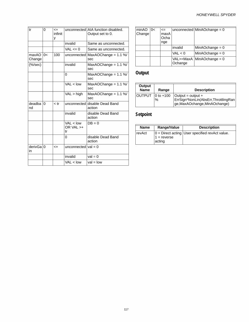
HONEYWELL SPYDER
117
Output
Setpoint
tr 0 <+ infinity
unconnected AIA function disabled. Output set to 0.
invalid Same as unconnected.VAL <= 0 Same as unconnected.
maxAOChange
0< 100 unconnected MaxAOChange = 1.1 %/sec
(%/sec) invalid MaxAOChange = 1.1 %/sec
0 MaxAOChange = 1.1 %/sec
VAL < low MaxAOChange = 1.1 %/sec
VAL > high MaxAOChange = 1.1 %/sec
deadband
0 < tr unconnected disable Dead Band action
invalid disable Dead Band action
VAL < low OR VAL >+ tr
DB = 0
0 disable Dead Band action
derivGain
0 <+ unconnected val = 0
invalid val = 0VAL < low val = low
minAOChange
0< <= maxAOchange
unconnected MinAOchange = 0
invalid MinAOchange = 0VAL < 0 MinAOchange = 0VAL>=MaxAOchange
MinAOchange = 0
Output Name Range Description
OUTPUT 0 to +100 %
Output = output + ErrSign*NonLin(AbsErr,ThrottlingRange,MaxAOchange,MinAOchange)
Name Range/Value DescriptionrevAct 0 = Direct acting
1 = reverse acting
User specified revAct value.

HONEYWELL SPYDER
118
CyclerThis function is a generic stage driver or a Thermostat Stage Cycler dependant on the value of the CPH parameter (cph=0 means stager functionality, and cph=1-60 gives thermostat cycler functionality).
Logic Inputs
Analog Inputs
Output
Setpoints
Configuration 1. Specify CPH from 0 to 60.2. Specify Anticipator Authority from 0 to 200%. Typical
value is 100%.3. Specify hysteresis from 0 to 100.
Input Name
Input Value
Logic Value Description
disable unconnected
0 Normal operation
VAL != 0.0 1 Disable block, output = 00 0 Normal operationinvalid 0 Normal operation
overrideOff
unconnected
0 Normal operation
VAL != 0.0 1 Turns off stages as min on time allows.
0 0 Normal operationinvalid 0 Normal operation
RangeInput Name Low High
Input Value Description
in 0 100 unconnected
stgsAct = 0
(%) invalid in = 0%
maxStgs
1 255 unconnected
stgsAct = 0
invalid maxStgs = 1minOn 0 6553
5unconnected
stgsAct = 0
(sec) invalid stgsAct = 0minOff 0 6553
5unconnected
stgsAct = 0
(sec) invalid stgsAct = 0intstgOn
0 65535
unconnected
stgsAct = 0
(sec) invalid stgsAct = 0intstgOff
0 65535
unconnected
stgsAct = 0
(sec) invalid stgsAct = 0
Output Name Range Description
STAGES_ACTIVE
0 to +100 %
The number of stages active (on)
NameRange/Value Description
anticipatorAuthority
0 to 200% User specified value. Typical value 100%
cph 0 to 60 User specified value.hyst 0 to 100 User specified value.

HONEYWELL SPYDER
119
Cycler FunctionalityThe Cycler function is the traditional anticipator cycling algorithm used in Honeywell thermostats. Input is ether P or PI space temperature error in% (0-100). Standard (recommended) settings are cph=3 for cooling, cph = 6 for heating, anticAuth = 100%, hyst = 100%/maxstages/2. Also note that for multiple stage cyclers the PID block feeding this block should have an appropriately large throttling range to achieve smooth behavior.

HONEYWELL SPYDER
120
Stager FunctionalityThe Stager Function takes a 0-100 percent (typically PID error) input and determines how many stages to turn on. The 0-100 percent input range is divided evenly between how many stages are configured in MaxStages. The first stage is turned on at CmdPercent > 0 and off at CmdPercent < - Hyst. As shown in following illustration the general criterion for turning on stage N is:
CmdPercent > (N -1)*100%/MaxStages.
For turning off stage N the criterion is:
CmdPercent < (N -1)*100%/MaxStages – Hyst.
From iteration to iteration, the Function Block keeps track of the on timer, off timer, anticipator, and CPH multiplier. On power up/reset, the off timer and anticipator are cleared, the on timer is set equal to the inter-stage on time and the CPH multiplier is recalculated.
When override is true, active stages are shed (turned off) based on min on and interstage timers regardless of the CmdPercent input. Output is number of stages active (0-MaxStages) which can be sent to the StageDriver function block. Configuration parameters include:
• MaxStages is the maximum stages available to turn on. • CPH (non-zero) is max cycle rate in Cycles Per Hour when
input is halfway between stages available and AnticAuth is at default value (100%). CPH = 0 means the Stager logic is performed and has no other effect.
• Hyst is the switching differential around the switch points in % error. (Range: 0 < Hyst < 100/Maxstgs.)
• AnticAuth (cycler only (CPH != 0)) is the anticipator authority, which allows adjustment of the cycling behavior. It represents the max amount of “fake” error in % that is input into the switching logic when MaxStages are turned on. (Range 0 < AnticAuth < 200.)
• MinOnTime is minimum time a stage must be on once it is turned on.
• MinOffTime is minimum time a stage must be off once it is turned off.
• InterstageOn is minimum time before the next stage can be turned on after the previous one is turned on.
• InterstageOff is minimum time before the next stage can be turned off after the previous one is turned off.

HONEYWELL SPYDER
121
Flow ControlThis function is a Variable Air Volume (VAV) Damper Flow Controller. Traditionally this is the second half of a pressure independent VAV box cascade control strategy where typically the input would come from the output of a PID block controlling space temperature.
Analog Inputs
RangeInput Name Low High Input Value Description
cmdFlowPercent(%)
0 <+ unconnected cmdFlowPercent= 0
invalid Same as unconnected.sensedFlowVol >=- infinity <+ infinity unconnected damperPos = cmdFlowPercent
invalid damperPos = cmdFlowPercentminFlowSetPt >=- infinity <+ infinity unconnected Switch to Pressure dependant mode.
minFlowSetPt = 20maxFlowSetPt = 100effFlowSetPt = invalid
invalid Same as unconnectedmaxFlowSetPt >=- infinity <+ infinity unconnected Switch to Pressure dependant mode.
minFlowSetPt = 20maxFlowSetPt = 100effFlowSetPt = invalid
invalid Same as unconnectedmanFlowOverride >=- infinity <+ infinity unconnected Normal operation
invalid Same as unconnected.manFlowValue 0 <+ infinity unconnected value = invalid
invalid Same as unconnected.ductArea >0 <+ infinity invalid effFlowSetPt = invalid & damperPos = (100*
minFlowSetPt/ maxFlowSetPt) unconnected Same as invalidVAL <= 0 Same as invalid

HONEYWELL SPYDER
122
Output
Setpoints
Configuration • Specify the units from 0 to 2.
— 0 = flow (cfm), area(ft**2)— 1 = flow (Lps), area (m**2)— 2 = flow (cmh), area (m**2).
• Specify the motor speed from 1 to 255 seconds per 90 degrees. Default is 90.
The Flow Controller function calculates an effective flow control set point (effFlowSetPt) and outputs a 0 -100 percent command to drive a VAV box damper. The commanded flow set point (in percent) from a temperature control signal is mapped into the effective flow set point such that 0 percent maps to the min flow set point and 100 percent maps to the max flow set point. The sensedFlowVol input is the volumetric flow into the box, if it is invalid (sensor fails) the damper is driven in a pressure dependant mode where:
Output = 100%*(minSP/maxSP)+ (1-minSP/maxSP)*cmdPercent.
If either flow MinSP, MaxSP is invalid, the output = 20% + .8*cmdPercent.
The Units parameter sets the units being used for the flow sensor, set points, and duct area where 0 = cfm (flow) and ft2 (area), 1 = L/s(flow) and m2(area), 2 = m3/hr(flow) and m2(area). The cmdFlowPercent input is the input in percent from the temperature control logic. DuctArea is the duct area in units per the Units parameter selection. DuctArea is required for the control algorithm. The control loop is implemented in air velocity in order to simplify loop tuning. The motorSpeed parameter is the time the actuator being used takes to travel a full 90 deg stroke in seconds (this is used to automatically adjust the control gains). The manFlowOverride input allows the flow set point to be selectively overridden based the following codes: (taken from snvt_hvac_overid)
— 0 and all others not listed = no override (normal opera-tion)
— 2 = effFlowSetPt is set to the ManFlowValue input— 6 = effFlowSetPt is set to the minFlowSetPt input— 7 = effFlowSetPt is set to the maxFlowSetPt input
Manual flow override is particularly useful when trying to make the box easy to be balanced.
Output Name Range DescriptionEFF_FLOW_SETPT Any floating point value Effective Flow setpointDAMPER_POS Any floating point value Damper position.
Name Range/Value Descriptionunits 0 to 2 0 = flow (cfm), area(ft**2)
1 = flow (Lps), area (m**2)2 = flow (cmh), area (m**2). Default is zero (0).
motorSpeed 1 to 255 seconds per 90 degrees
Default is 90

HONEYWELL SPYDER
123
PIDThe PID controller compares a measured value from a process with a reference setpoint value. The difference (or error signal) is then used to calculate a new value for a manipulatable input to the process that brings the process' measured value back to its desired setpoint. Unlike simpler control algorithms, the PID controller can adjust process outputs based on the history and rate of change of the error signal, which gives more accurate and stable control.
In a PID loop, correction is calculated from the error in three ways:
• Cancel out the current error directly (Proportional)• The amount of time the error has continued uncorrected
(Integral)• Anticipate the future error from the rate of change of the
error over time (Derivative)— Err = Sensor – Set Point— Kp = 100/Proportional Band— Ti = Integral Time (seconds)— Td = Derivative Time (sec)— Bias = proportional offset (%)— Output (%) =bias + Kp*Err + Kp/Ti +
Kp*Td*dErr/dt
Logic Inputs
Analog Inputs
∫t
dtErr0
)(
Input Name
Input Value
Logic Value Description
disable unconnected
0 PID function runs.
VAL != 0.0 1 PID function is disabled. Output set to zero.
0 0 PID function runs.invalid 0 PID function runs.
RangeInput Name Low High Input Value Description
sensor >=- infinity <+ infinity unconnected PID function disabled. Output set to 0.
invalidsetPt >=- infinity <+ infinity unconnected PID function disabled.
Output set to 0.invalid Same as unconnected.
tr 0< <+ infinity unconnected PID function disabled. Output set to 0.
invalid Same as unconnected.0 PID function disabled.
Output set to 0VAL < low val = low
intgTime 0 <+ infinity unconnected PID function disabled.Output set to 0.
(sec) invalid Disable Integral Action.0 Disable Integral Action.VAL < low IT = low
dervTime 0 <+ infinity unconnected Disable Derivative action.(sec) invalid Disable Derivative action.
0 Disable Derivative action.VAL < low DT = low
deadBand 0 < tr unconnected same as 0 inputinvalid same as 0 inputVAL < low or VAL >= tr
DB = 0
0 disable Dead Band actiondbDelay 0 65565 dead band delay

HONEYWELL SPYDER
124
Output
Setpoints
Configuration1. Specify Action
• 0 = Direct acting
• 1 = reverse acting
2. Specify the bias: 0 to 100%.When Disable/Initialize input is TRUE, The Output and the integral are set to 0 and the block stops running. If Direct/Reverse is set to reverse, then Err term is set to –Err.
When Err < Dead band, Err is set to zero until Dead band Delay time has elapsed and Err is still in the dead band.
To prevent integral wind up, the integral portion of the total error output is limited to 100%.
From iteration to iteration, the Function Block keeps track of the old proportional error, integral error, and dead band timer. On power up/reset these are cleared.
(sec) unconnected same as 0 inputinvalid same as 0 input0 dead ban action enabled without delayVAL < low DeadBandDelay = low
Output Name Range DescriptionOUTPUT -200 to +200 %
Output (%) =bias + Kp*Err + Kp/Ti + Kp*Td*dErr/dt∫t
dtErr0
)(
Name Range DescriptionAction 0 = Direct acting
1 = reverse actingUser specified inputs
bias 0 to 100% User specified inputs

HONEYWELL SPYDER
125
Rate LimitThis function creates an output that follows the input but prevents the output from changing faster that the specified rates depending on direction.
Logic Inputs
Analog Inputs
Output
OperationThe value StartInterval (sec) limits the output after the rate limit function is enabled (disable input set to 0) and the StartInteval time is still in process. Ratelimit uses the startVal input as the default output during disable.
If the rate limit function is disabled (disable input set to 1) the output will be set to StartVal.
After rateLimit is enabled (disable set to 0) the StartInterval timer will count down from the StartInterval number of seconds and during this time the output will be rate limited.
When the timer expires (and ratelimit is enabled) the out value will be exactly what the input (in) is set to and there will no longer be rate limiting.
If the StartInterval seconds is set to 0 (and ratelimit is enabled), then the output will be Ratelimited.
During Ratelimit the output will move at a maximum allowed rate toward the new input value each second.
UpRate controls the rate in a more positive direction, and DownRate controls the rate in a more negative direction. UpRate set to zero means the uprate limit is not enforced. DownRate set to zero means the downrate limit is not enforced.
Out is set to StartVal before rate limiting is enabled (disable set to 0).
From iteration to iteration, the Function Block keeps track of the start timer. On power/up/reset, this is set to the StartInterval.
Input Name
Input Value
Logic Value Description
disable unconnected
0 Function runs.
VAL != 0.0 1 Function disabled0 0 Function runs.invalid 0 Function runs.
RangeInput Name Low High
Input Value Description
in >=- infinity
<+ infinity
unconnected
In= 0.0
invalid In = InvalidValid In = value
startInterval
0 65535 unconnected
Startinterval = 0
(sec) invalid Start interval = 00<val<max float
Limit Start interval value 0 to 65535.0 seconds
<0 StartInterval = 0 startVal >=-
infinity
<+ infinity
Output assumes the start value when the function is disabled.
unconnected
If disable=1, then Out=in
invalid If disable=1, then Out=in
upRate 0< <+ infinity
unconnected
No limit on up rate
(chg/sec) invalid No limit on up rate0 no limit on up rate<0 upRate = 0 (no limit
on up rate)
downRate
0< <+ infinity
unconnected
no limit on down rate
(chg/sec) invalid no limit on down rate0 no limit on down rate<0 downRate=0 (no limit
on up rate)
Output Name Range Description
OUTPUT Any floating point value
Rate limit
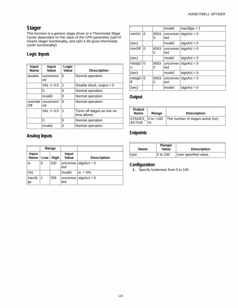
HONEYWELL SPYDER
126
StagerThis function is a generic stage driver or a Thermostat Stage Cycler dependant on the value of the CPH parameter (cph=0 means stager functionality, and cph=1-60 gives thermostat cycler functionality).
Logic Inputs
Analog Inputs
Output
Setpoints
Configuration 1. Specify hysteresis from 0 to 100.
Input Name
Input Value
Logic Value Description
disable unconnected
0 Normal operation
VAL != 0.0 1 Disable block, output = 00 0 Normal operationinvalid 0 Normal operation
overrideOff
unconnected
0 Normal operation
VAL != 0.0 1 Turns off stages as min on time allows.
0 0 Normal operationinvalid 0 Normal operation
RangeInput Name Low High
Input Value Description
in 0 100 unconnected
stgsAct = 0
(%) invalid in = 0%maxStgs
1 255 unconnected
stgsAct = 0
invalid maxStgs = 1minOn 0 6553
5unconnected
stgsAct = 0
(sec) invalid stgsAct = 0minOff 0 6553
5unconnected
stgsAct = 0
(sec) invalid stgsAct = 0intstgOn
0 65535
unconnected
stgsAct = 0
(sec) invalid stgsAct = 0intstgOff
0 65535
unconnected
stgsAct = 0
(sec) invalid stgsAct = 0
Output Name Range Description
STAGES_ACTIVE
0 to +100 %
The number of stages active (on)
NameRange/Value Description
hyst 0 to 100 User specified value.

HONEYWELL SPYDER
127
Cycler FunctionalityThe Cycler function is the traditional anticipator cycling algorithm used in Honeywell thermostats. Input is ether P or PI space temperature error in% (0-100). Standard (recommended) settings are cph=3 for cooling, cph = 6 for heating, anticAuth = 100%, hyst = 100%/maxstages/2. Also note that for multiple stage cyclers the PID block feeding this block should have an appropriately large throttling range to achieve smooth behavior.

HONEYWELL SPYDER
128
Stager FunctionalityThe Stager Function takes a 0-100 percent (typically PID error) input and determines how many stages to turn on. The 0-100 percent input range is divided evenly between how many stages are configured in MaxStages. The first stage is turned on at CmdPercent > 0 and off at CmdPercent < - Hyst. As shown in following illustration the general criterion for turning on stage N is:
CmdPercent > (N -1)*100%/MaxStages.
For turning off stage N the criterion is:
CmdPercent < (N -1)*100%/MaxStages – Hyst.
From iteration to iteration, the Function Block keeps track of the on timer, off timer, anticipator, and CPH multiplier. On power up/reset, the off timer and anticipator are cleared, the on timer is set equal to the inter-stage on time and the CPH multiplier is recalculated.
When override is true, active stages are shed (turned off) based on min on and interstage timers regardless of the CmdPercent input. Output is number of stages active (0-MaxStages) which can be sent to the StageDriver function block. Configuration parameters include:
• MaxStages is the maximum stages available to turn on. • CPH (non-zero) is max cycle rate in Cycles Per Hour when
input is halfway between stages available and AnticAuth is at default value (100%). CPH = 0 means the Stager logic is performed and has no other effect.
• Hyst is the switching differential around the switch points in % error. (Range: 0 < Hyst < 100/Maxstgs.)
• AnticAuth (cycler only (CPH != 0)) is the anticipator authority, which allows adjustment of the cycling behavior. It represents the max amount of “fake” error in % that is input into the switching logic when MaxStages are turned on. (Range 0 < AnticAuth < 200.)
• MinOnTime is minimum time a stage must be on once it is turned on.
• MinOffTime is minimum time a stage must be off once it is turned off.
• InterstageOn is minimum time before the next stage can be turned on after the previous one is turned on.
• InterstageOff is minimum time before the next stage can be turned off after the previous one is turned off.

HONEYWELL SPYDER
129
Stage DriverThe StageDriverMaster function takes input number of stages active and determines which stages to energize or de energize based on the lead/lag strategy chosen. Stage Driver works with StageDriverAdd to distribute additional stages above those provided in Stage Driver. Stage Driver also maintains a nonvolatile runtime total and digital stage status information for each stage.
The configuration tool will set a runtime and stage stages offset in a single offsets variable. The offsets variable is not used as a Public Variable ID. The lower byte will store the offset in digital memory to reference the starting stage status memory index, and the upper byte will store the offset in
nonvolatile memory to reference the starting runtime memory index. stgStatusOut is the offset to digital stage status that is used by connected StageDriverAdd blocks.
As more stages are set up during design, the configuration tool will calculate the starting address for both stage status and runtime and allocate the memory and calculate the offset from the base index that is the starting address for the runtime area and the stage status area in their respective memories.
The stage status information is accessible to drive additional stages. The StageDriverAdd function blocks are use to drive stages above those provided in Stage Driver up to 255 stages.
Analog Inputs
Outputs
RangeInput Name Low High Input Value Description
nStagesActive 0 255 unconnected Stages all offinvalid Stages all off
runtimeReset 0 255 Unconennected No action to reset; runtime can accumulateInvalid No action; runtime can accumulateValue=0 No action; runtime can accumulate1<=VAL<=255 Stage runtime for stage VAL is reset to 0; runtime for this
stage will not accumulate—you must reset VAL to 0 to allow accumulation of runtime.
RangeOutput Name Low High Description
Stage1 0 1 Stage 1 output Stage2 0 1 Stage 2 output Stage3 0 1 Stage 3 output

HONEYWELL SPYDER
130
ConfigurationSpecify the maximum number of stages (maxStgs) from 1 to 255.
Specify the lead lag (leadlag)
• LL STD = 0 first on last off• LL FOFO = 1 first on first off• LL RUNEQ = 2 runtime equalization for lowest runtimeIf the leadlag is outside of the range of 0 - 2 then stages are initialized to off and not commanded.
InputsnStagesActive is the input number of stages to be distributed to on/off values to individual stages.
runtimeReset is the stage number runtime to be reset to 0 if the lead-lag parameter is set to LL RUNTIME. 0 or unconnected results in no reset occurring. This value must be returned to 0 to allow the reset stage number to resume counting. Only valid if leadLag is set to LL RUNTIME. The stage runtime values are only allocated and updated if the leadLag config is set to LL RUNTIME. The runtime for each stage is stored as a floating point number in intervals of 1 minute.
The stages are sampled once a minute and if the stage is on, then the stage runtime accumulator number for that stage is incremented by one minute. The range of values for an integer number stored as a float is from -16,777,216 to 16,777,216. If the runtime is stored in minutes starting at 0 to 16,777,216, then the range of runtime is from 0 to 31.92 years of runtime.
OutputsStage1, stage2, stage3, stage4, and stage5 are individual outputs that represent on or off values. These are outputs that are turned on in different order depending on the leadLag strategy.
stgStatusOut is connected from StageDriver to the StageDriverAdd block and gives a floating point number combined to hold two pieces of information, offset in the Common Memory to the StageBitStatus values and maximum number of stages available. This information is used by the StageDriverAdd to find the correct offset to command which stages to turn on or off. The floating value can be converted to an integer and ANDed with 0xFF and will give the value of the stageStatus Offset. The floating value stgStatusOut converted to an integer and right shifted 8 bits will give the byte value of
the maxStages. These values are needed to allow the StageDriverAdd to work properly. The values in stgStatusOut are created by the StageDriver stage and no tool calculation is required.
Offsets store the public Variable ID to a float a value created by the tool to allocate storage memory and reference for stage status in digital memory and stage runtime in nonvolatile memory. There are two offsets stored inside the float value, one for runtime, and one for stage status. The offset float value right shifted 8 bits gives the number of nonvolatile float values from the beginning nonvolatile index (offset) where the runtime values are stored (one runtime value offset for each stage configured), and the offset ANDED with 0xff gives the number of digital values from the base where the stagestatus is stored (one byte per up to 8 stages configured). Each digital memory location takes up 1 byte storage in calculating the offset.
Example
If three nonvolatiles were already assigned and four digital outputs were already assigned before adding a stagedriver stage of nine stages with runtime accumulation, then the offset float value would be 256(3) + 4 = 772.0.
That means the tool would have 8 nonvolatile runtime locations starting at offset 3 from the base of nonvolatile memory and the tool would allocate digital memory of two bytes for the stage status starting at offset of 4 from the base of digital memory. The tool sets this float value for offsets and allocates the memory, and then stagedriver uses this information to know where to look for stagestatus and stage runtime information.
The Float value that stores Offsets is composed of two values
• offsetStageRuntimer (byte) The float value converted to an integer and shifted 8 bits specifies the variable quantity offset to be applied to the beginning of nonvolatile memory variable number that indicates the starting variable number used to store the individual stage runtime values. This number is calculated by the configuration tool and is not changeable.
• offsetStageStatus (byte) The float value converted to an integer and anded with 0xFF specifies the variable number offset to be applied to the beginning of digital memory area that indicates the starting variable number used to store the individual stage on/off
Stage4 0 1 Stage 4 output Stage5 0 1 Stage 5 output stgStatusOut Output value to connect to StageDriverAdd block. The floating number must be
converted to an integer and then converted to a 2 byte value. The upper byte (value right shifted 8 bits) is the maxStgs info and the lower byte(value AND 0xFF) is the stageStatus offset to reference the starting location in digital memory for the stageStatus bytes.
offset Float value has two components – after conversion to a two byte unsigned integer value the upper byte is offset of number of nonvolatile entries to get to the start of the stage runtime storage (used only for leadLag=LL-RUNEQ) and the lower byte is the offset of number of digital memory locations to the start of the stage status bytes (one byte allocated per 8 stages assigned in maxStgs)

HONEYWELL SPYDER
131
values. This number is calculated by the configuration tool and is not changeable. This value is exported to other stages through the stageBitStatus output.
ParametersleadLag (Byte param:UBYTE) specifies whether the staging strategy should be:
• First on last off (LL STD = 0 - standard)• First on first off (LL FOFO = 1 - Rotating)• Run time accumulation where next on is lowest runtime
and next off has highest runtime (LL RUNTEQ = 2 - Runtime Accumulation)
Runtime Accumulation selection requires the tool to allocate Nonvolatile memory and Set the Offsets value.
Example
In a boiler control system configured for a maximum stages of 4, LL STD will take the number of stages active and activate the stages in the following order, stage 1 on, then stage1 and stage 2 on, then stage 1 on stage2 on stage3 on, then stage 1 on stage2 on stage3 on and stage 4 on. When one stage is removed then it will be stage 1 on stage 2 on stage 3 on. If one more stage is removed then it will be stage 1 on stage 2 on. If one more stage is removed then stage 1 on, and finally if one more stage is removed then there is only one stage on. And finally if one more stage is removed then no stages are on. Stage 1 always comes on first and is always the last stage to turn off.
If we take this same example and implement it as a LL FOFO which is rotating or First on first off, then the boiler keeps track of where the starting stage is from the last cycle. Say for example there are no stages on and a stage is added. Then adding one stage will turn on stage1. If another stage is added, then stage1 is on and stage2 is on. If one more stage is added then stage1 is on stage2 on and stage 3 is on. Now lets say that the number of stages goes from 3 to 2 so now it is time to remove a stage. Because of LL FOFO, the first stage we turned on is the first stage to turn off so stage 1 would go off and only stage 2 and stage 3 would be on. Then if you
were to turn off one more stage then stage 2 would go off and only stage 3 would be on. Now if you added one more stage, stage 4 would turn on in addition to stage 3. If One more stage were added (numstages = 3) then stage 3 is on, stage 4 is on, and now stage 1 turns on too.
For a final example, let us take the example of LL RUNTEQ for a sequence. Each stage now has a runtime accumulation in minutes. So let us assume that all 4 stages turn on for 12 minutes. Each stage for stage1, stage2, stage3, and stage 4 is on and accumulates 12 minutes of runtime. Now it is time to turn off one stage so all the ON stages are evaluated for the highest runtime and since they are all the same, the last stage that is on that is evaluated has the highest runtime so stage 4 is turned off so stage 1 on stage2 on and stage3 = on. Now let us run the boilers for 2 more minutes. Now stage 1 has 14 minutes runtime, stage 2 has 14 minutes runtime, stage 3 has 14 minutes runtime, and stage 4 has 12 minutes runtime. Now the number of stages requested drops to 2 stages so stage 3 is turned off and now stage 1 on, stage 2 on, stage 3 off, and stage 4 off. So now the boilers are run for 2 more minutes. The runtimes are now stage 1 on = 16 minutes, stage 2 on =16 minutes, stage 3 = off =14 minutes, and stage 4 = off = 12 minutes. Now let us add one more stage so number of stages goes from 2 to 3. Now all the stages that are off are evaluated for lowest runtime. Stage 4 has the lowest runtime of 12 minutes so now stage 4 is turned on.
maxStages (Byte param:UBYTE) specifies how many total stages nStagesActive can reach. MaxStages can go up to a total of 255 stages.
Note: Due to limitations of Niagara, only 95 stages can be seen on the wiresheet. To see, say stage number 200, do one of the following:
Select the stages (in this case, stage 200) you want to see by right-clicking them in the Block Configuration table under Show Stages and select Show.
Invoke the link editor on the wire sheet. Select the Source and the Target (in this case, stage 200).
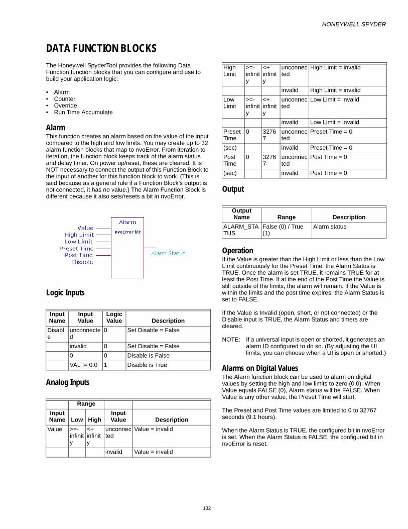
HONEYWELL SPYDER
132
DATA FUNCTION BLOCKSThe Honeywell SpyderTool provides the following Data Function function blocks that you can configure and use to build your application logic:
• Alarm• Counter• Override• Run Time Accumulate
AlarmThis function creates an alarm based on the value of the input compared to the high and low limits. You may create up to 32 alarm function blocks that map to nvoError. From iteration to iteration, the function block keeps track of the alarm status and delay timer. On power up/reset, these are cleared. It is NOT necessary to connect the output of this Function Block to the input of another for this function block to work. (This is said because as a general rule if a Function Block’s output is not connected, it has no value.) The Alarm Function Block is different because it also sets/resets a bit in nvoError.
Logic Inputs
Analog Inputs
Output
OperationIf the Value is greater than the High Limit or less than the Low Limit continuously for the Preset Time, the Alarm Status is TRUE. Once the alarm is set TRUE, it remains TRUE for at least the Post Time. If at the end of the Post Time the Value is still outside of the limits, the alarm will remain. If the Value is within the limits and the post time expires, the Alarm Status is set to FALSE.
If the Value is Invalid (open, short, or not connected) or the Disable input is TRUE, the Alarm Status and timers are cleared.
NOTE: If a universal input is open or shorted, it generates an alarm ID configured to do so. (By adjusting the UI limits, you can choose when a UI is open or shorted.)
Alarms on Digital ValuesThe Alarm function block can be used to alarm on digital values by setting the high and low limits to zero (0.0). When Value equals FALSE (0), Alarm status will be FALSE. When Value is any other value, the Preset Time will start.
The Preset and Post Time values are limited to 0 to 32767 seconds (9.1 hours).
When the Alarm Status is TRUE, the configured bit in nvoError is set. When the Alarm Status is FALSE, the configured bit in nvoError is reset.
Input Name
Input Value
Logic Value Description
Disable
unconnected
0 Set Disable = False
invalid 0 Set Disable = False0 0 Disable is FalseVAL != 0.0 1 Disable is True
RangeInput Name Low High
Input Value Description
Value >=- infinity
<+ infinity
unconnected
Value = invalid
invalid Value = invalid
High Limit
>=- infinity
<+ infinity
unconnected
High Limit = invalid
invalid High Limit = invalidLow Limit
>=- infinity
<+ infinity
unconnected
Low Limit = invalid
invalid Low Limit = invalidPreset Time
0 32767
unconnected
Preset Time = 0
(sec) invalid Preset Time = 0Post Time
0 32767
unconnected
Post Time = 0
(sec) invalid Post Time = 0
Output Name Range Description
ALARM_STATUS
False (0) / True (1)
Alarm status

HONEYWELL SPYDER
133
View AlarmsTo view the alarms that are generated, right click LonHoneywell in the Nav palette and select Views > Alarms View.
The Alarms View is displayed.
There are 4 categories of alarms:
• Sensor Alarms: These alarms are generated for all the Sensors configured in the logic. All input blocks assigned to pins UI0 to UI7 will be listed in this category.
• Invalid ConfigurationAlarms: This alarm will occur if there is an error in the configuration that was downloaded.
• Network Communication Alarms: These alarms will occur ONLY for Network variable inputs (NVIs) configured as fail detect. The network variable names will be listed in this category.
• Control Alarms: All the alarm blocks configured in the logic will be listed in this category. If an alarm block does not have any incoming link then the status will always be NORMAL.
Alarm State Value Timer Action CommentFalse Outside
limits< Preset Time Increment Timer. Insure alarm is valid for the preset time before
issuing the alarm.False Outside
limits>= Preset Time Set Alarm Status = TRUE;
Clear TimerThe preset time has been met, post alarm and clear the timer so it can count the post time.
False Inside limits Don’t care Clear Timer Value is inside the limits and there is no prior alarm, so clear the timer so it’s ready to count the preset time when the value goes outside [again].
True Outside limits
< Post Time Increment Timer Insure that we post the alarm for at least Post Time seconds regardless of what the value does with respect to the limits.
True Outside limits
>= Post Time Stop Timer The alarm has been issued for at least the Post Time. The alarm is now allowed to return to normal as soon as the value goes back within the limits.
True Inside limits < Post Time Increment Timer Value has gone back inside the limits after posting the alarm. Wait until the timer expires before issuing the return to normal.
True Inside limits >= Post Time Clear Alarm Status;Clear Timer
The alarm has been issued for at least the Post Time. Clear the alarm because the conditions are no longer present.

HONEYWELL SPYDER
134
CounterThis function counts leading edge transitions of the input. If enable is True and the input transitions from False to True, then the count is incremented or decremented by the count value. Positive values on count value increment the count. Negative values decrement the count. If preset is True, the count is set to the Preset Value. From iteration to iteration, the Function Block keeps track of the previous state of the input so that it can detect a transition. On power up/reset, this is cleared.
Logic Inputs
Analog Inputs
Output
Input Name
Input Value
Logic Value Description
Input unconnected
0 Set Input = False
invalid 0 Set Input = False0 0 Input is FalseVAL != 0.0 1 Input is True
Enable unconnected
1 Set Enable = True
invalid 1 Set Enable = True0 0 Set Enable = FalseVAL != 0.0 1 Set Enable = True
Preset unconnected
0 Set Preset = False
invalid 0 Set Preset = False0 0 Set Preset = FalseVAL != 0.0 1 Set Preset = True
StopAtZero
unconnected
0 Set Stop At Zero = False. Default value is False.
invalid 0 Set Stop At Zero = False.0 0 Stop At Zero is False. Count is
unaffected by a zero value.VAL != 0.0 1 Stop At Zero is True. Stops
counting at zero if counting down from a positive count or up from a negative count.
RangeInput Name Low High
Input Value Description
CountValue
>=- infinity
<+ infinity
unconnected
Set Count Value = 1.0 Default value = 1.0
Invalid Set Count Value = 1.0VAL < low
Set Count Value = 1.0
VAL > high
Set Count Value = 1.0
PresetValue
>=- infinity
<+ infinity
unconnected
Set Preset Value = 0.0
Invalid Set Preset Value = 0.0VAL < low
Set Preset Value = 0.0
VAL> high
Set Preset Value = 0.0
Output Name Range DescriptionCOUNT Any floating point
numberCounter value

HONEYWELL SPYDER
135
Transition versus time with positive and negative count values

HONEYWELL SPYDER
136
OverrideThis function sets the output to the highest priority input that is not invalid. The Priority1 value has the highest priority and cntrlInput the Lowest priority. This function block checks if the Inputs are not invalid in the following order:
1. Priority 1 Value2. Priority 2 Value3. Priority 3 Value4. Priority 4 Value5. Priority 5 Value6. Priority 6 Value7. Ctrl Input
The first value that is not invalid in the order of priority is set as the output. If all inputs are invalid or unconnected, the output is set to the defaultValue.
This function block corresponds to the BACnet priority array implementation with the replacement of the BACnet NULL state with invalid.
Analog Inputs
Output
Example
Set the Inputs to the following:
• Priority 1 Value = Invalid• Priority 2 Value = Invalid• Priority 3 Value = 50• Priority 4 Value = 60• Priority 5 Value = -20• Priority 6 Value = 80• Ctrl Input = 30The output is set as 50. Priority 1 and Priority 2 values are invalid. The next highest priority value (Priority 3 value = 50) is set as the output.
An invalid input to this function block could arise when you connect the output of the Minimum function block whose input is invalid.
RangeInput Name Low
High
Input Value Description
priority1Value through priority6Value
>=- infinity
<+ infinity
Unconnected or invalid
Output = highest priority input (priority1Val is top priority and cntrlInput is lowest priority) that is not invalid or unconnected. If no inputs are valid, then use defaultValue
cntrlInput >=- infinity
<+ infinity
Unconnected or invalid
Output = highest priority input (priority1Val is top priority and cntrlInput is lowest priority) that is not invalid or unconnected. If no inputs are valid, then use defaultValue
defaultValue
>=- infinity
<+ infinity
unconnected
defaultValue = invalid
invalid defaultValue = invalid
RangeOutput Name Low High Description
EFF_OUTPUT
>=- infinity
<+ infinity
effOutput = highest priority input that is not invalid.

HONEYWELL SPYDER
137
Priority OverrideThe PriorityOverride block supports driving the outputs based on the priority of the connected application components. There can be different control program logic components driving the outputs at different priority levels. This block decides the priority level at which the output must be driven. This block supports up to 16 priority levels that can be connected to different application components.
The Priority1 value has the highest priority and Priority 16 the lowest priority. The block provides an output called PriorityOut. The value of the highest priority is set as the output PriorityOut. The PriorityOut slot of the PriorityOverride block can be linked only to a modulating/binary output.
The block can be used in both LON and BACnet applications. This block provides the PriorityArray mechanism in case of BACnet objects. This block details do not get downloaded to the controller in case of BACnet. In case of LON, the PriorityArray mechanism is internally achieved using Override blocks. The information of the override blocks get downloaded to the LON controller. Hence there would be a difference in function block count between BACnet and LON application when this block is used.
During upload the PriorityOverride block is depicted as part of the ControlProgram, depending on the number of application components driving the outputs. If there is only one application components driving the output, the ControlProgram wiresheet would show a direct link from that application component to the output. If there are more than one application component driving the output, the PriorityOverride block would be depicted in the logic with outputs being driven at different priority levels.
Analog Inputs
Output
Example
Set the Inputs to the following:
1. Priority 1 = Unconnected 2. Priority 2 = Invalid 3. Priority 3 = 50 4. Priority 4 = 60 5. Priority 5 = -20 6. Priority 6 = 80 7. Priority 7 = 30 8. Priority 8 =Unconnected 9. Priority 9 =Unconnected
10. Priority 10 =Unconnected 11. Priority 11 =Unconnected 12. Priority 12 =Unconnected 13. Priority 13 =Unconnected 14. Priority 14 =Invalid 15. Priority 15 =40 16. Priority 16 =10
The output is set as invalid as Priority 2 is invalid. The highest priority value is set as the output.
The properties of the Priority Override function block are listed in the following table.
RangeInput Name Low
High
Input Value Description
priority1Value through priority16
>=- infinity
<+ infinity
Unconnected or invalid
Output = value of the highest priority input (priority1 is top priority and priority16 is lowest priority). If no inputs are valid, then the output is also invalid.
RangeOutput Name Low High Description
PriorityOut
>=- infinity
<+ infinity
PriotityOut = value of the highest priority input.
S.No. Description LON BACnet‘1 The input to the priority slot of the Priority Override function block can be a
physical point, a software point, or function blocks but cannot be a constant. Applicable Applicable
2 The PriorityOut slot can be connected to only one physical point which can be modulating output or binary output.
Applicable Applicable
3 The memory increment depends on the type of input block. Applicable Applicable4 The FB count in the Resource Usage View is only incremented when the
Priority Override block contains a Valid Link and a Valid Knob.Applicable Not Applicable

HONEYWELL SPYDER
Automation and Control SolutionsHoneywell International Inc. Honeywell Limited-Honeywell Limitée1985 Douglas Drive North 35 Dynamic DriveGolden Valley, MN 55422 Scarborough, Ontario M1V 4Z9www.honeywell.com/buildingsolutions
® U.S. Registered Trademark© 2009 Honeywell International Inc. HTS Rev. 07-09
5 If there are valid links from priority levels 1 to 8, FB count is incremented by 1.
Applicable Not Applicable
6 If there are valid links from priority levels 9 to 15, FB count is incremented by 2.
Applicable Not Applicable
7 If there are valid links greater than priority level 15, FB count is incremented by 3.
Applicable Not Applicable
8 The FB count in the Resource Usage View is not incremented. Not Applicable Applicable
S.No. Description LON BACnet‘

HONEYWELL SPYDER
139
Runtime AccumulateThis function accumulates runtime whenever the input is True (non zero) and enable is True. If Preset is True, runtime is set equal to the Preset Value. Runtime is provided in four outputs of seconds, minutes, hours, and days. From iteration to iteration, the Function Block keeps track of the run time seconds. On power up/reset, this is cleared.
NOTE: On power up/reset, only the Runtime Sec output is set to zero. The other three outputs, Runtime Min, Runtime Hrs, Runtime Days are stored and not lost.
Logic Inputs
Analog Inputs
Output
Input Name
Input Value
Logic Value Description
Input unconnected
0 Set Input = False
invalid 0 Set Input = False0 0 Input is FalseVAL != 0.0 1 Input is True
Enable unconnected
1 Set Enable = True
invalid 1 Set Enable = True0 0 Enable is False
VAL != 0.0 1 Enable is TruePreset unconnect
ed0 Set Preset = False
invalid 0 Set Preset = False0 0 Preset is FalseVAL != 0.0 1 Preset is True
RangeInput Name Low High
Input Value Description
Preset Value
0 <+8 unconnected
Set Preset Value = 0.0 (in minutes)
invalid Set Preset Value = 0.0VAL < low
Set Preset Value = 0.0
VAL > high
Set Preset Value = 0.0
Output Name Range Description
RUNTIME_MIN
Any floating point number >= 0
Runtime Min
RUNTIME_SEC
Any floating point number >= 0
Runtime Sec
RUNTIME_HRS
Any floating point number >= 0
Runtime Hrs
RUNTIME_DAYS
Any floating point number >= 0
Runtime Days
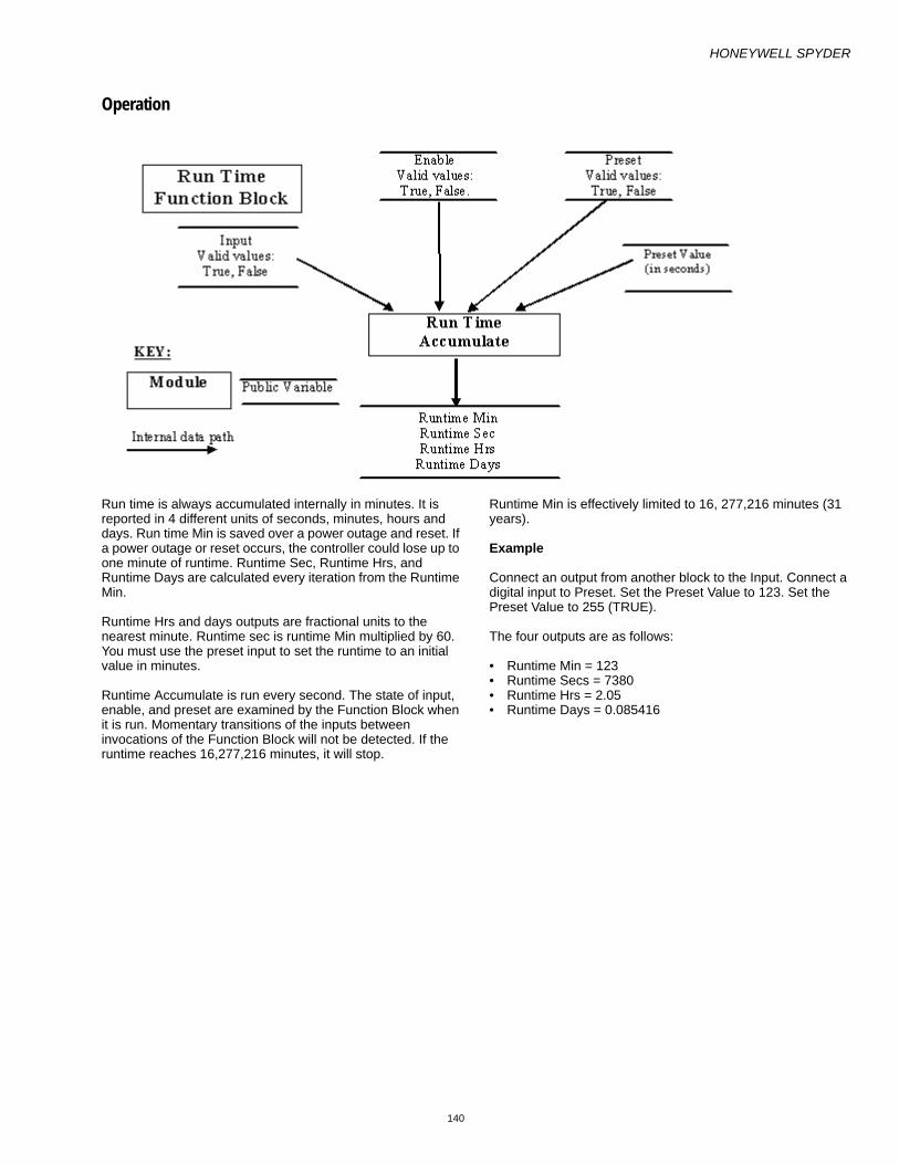
HONEYWELL SPYDER
140
Operation
Run time is always accumulated internally in minutes. It is reported in 4 different units of seconds, minutes, hours and days. Run time Min is saved over a power outage and reset. If a power outage or reset occurs, the controller could lose up to one minute of runtime. Runtime Sec, Runtime Hrs, and Runtime Days are calculated every iteration from the Runtime Min.
Runtime Hrs and days outputs are fractional units to the nearest minute. Runtime sec is runtime Min multiplied by 60. You must use the preset input to set the runtime to an initial value in minutes.
Runtime Accumulate is run every second. The state of input, enable, and preset are examined by the Function Block when it is run. Momentary transitions of the inputs between invocations of the Function Block will not be detected. If the runtime reaches 16,277,216 minutes, it will stop.
Runtime Min is effectively limited to 16, 277,216 minutes (31 years).
Example
Connect an output from another block to the Input. Connect a digital input to Preset. Set the Preset Value to 123. Set the Preset Value to 255 (TRUE).
The four outputs are as follows:
• Runtime Min = 123• Runtime Secs = 7380• Runtime Hrs = 2.05• Runtime Days = 0.085416

HONEYWELL SPYDER
141
LOGIC FUNCTION BLOCKSThe Honeywell SpyderTool provides the following Logic function blocks that you can configure and use to build your application logic:
• AND• One Shot• OR• XORInputs to Logic Function Block may come from either Digital or Floating point variables.
For digital inputs
• 0 = FALSE• 1-255 = TRUEFor floating point variables
• 0.0 = FALSE• any nonzero number = TRUEAn output sent to a Digital variable will be 0 or 1. Similarly, an output sent to a float point variable will be 0.0 or 1.0.
ANDAND output becomes TRUE if all inputs are TRUE. This function is a six-input AND Function Block. Each input may be individually inverted (NOT).
Unconnected or invalid inputs default to True, without negation, so as to have no effect on the result.
From iteration to iteration, the function block keeps track of the last computed output value and the current true or false delay time. These values are cleared on power up/reset.
Logic Inputs
Analog Inputs
Output
Example
1. Set In1- In6 = 1, and True delay = 2, and False delay = 6.
In this case, the output is set to 1 after a time delay of 2 seconds as specified by the True delay.
2. Set In1 = 0, In2 - In6 = 1, and True delay = 2, and False delay = 6.
In this case, the output is set to 0 after a time delay of 6 seconds as specified by the False delay.
Input Name
Input Value
Logic Value Description
in1-6 VAL != 0.0 10 0unconnected
1 Inputs with a "not" interpreted as logic 1 when disconnected.
invalid 1 Negin does not affect the invalid logic value.
RangeInput Name
Low High Input Value Description
trueDelay
0 32767
unconnected val = 0It is the minimum time the computed output must stay True before the output actually changes from False to True.
(sec) invalid val = 0falseDelay
0 32767
unconnected val = 0It is the minimum time the computed output must stay False before the output actually changes from True to False.
(sec) invalid val = 0
Output Name Range Description
OUTPUT Any floating point value
Output = AND/NAND (inputs).Negating the Output makes the AND function block behave like a NAND function block.

HONEYWELL SPYDER
142
OneshotIn the Oneshot function block, when x transitions from False to True, y is set to True for OnTime seconds.
OnTime is limited to the range 0 to 65535 seconds. An OnTime of zero keeps the output OFF no matter what changes occur at the x input.
Both the x input and y outputs have an option to be negated. From iteration to iteration, the Function Block keeps track of the last input and the on time. On power up/reset, these are cleared.
Logic Inputs
Analog Inputs
OutputInput Name
Input Value
Logic Value Description
x unconnected
N/A For an invalid input make output be OFF (ON if output is negated). Clear the timer
VAL != 0.0 10 0invalid N/A Must go from FALSE to
TRUE (or TRUE to FALSE (Negated))
RangeInput Name Low High
Input Value Description
onTime 0 65535
unconnected
onTime =0
(sec) invalid onTime =0< 0 0> 65535 65535
Output Name Range Description
Y Any floating point value
When x transitions from FALSE to TRUE, y will be set to TRUE (1) for onTime seconds

HONEYWELL SPYDER
143
Example
The Input is a square wave of 2 second amplitude. The time transition diagram of the Output for different ontimes of 1 and 5 seconds is illustrated.

HONEYWELL SPYDER
144
ORThe OR output becomes TRUE if at least one input is TRUE. This function is a six input OR. Each input may be individually inverted (NOT).
Unconnected or invalid inputs default to True, without negation, so as to have no effect on the result.
From iteration to iteration, the function block keeps track of the last computed output value and the current true or false delay time. These values are cleared on power up/reset.
Logic Inputs
Analog Inputs
Output
Input Name
Input Value
Logic Value Description
in1-6 VAL! = 0.0 10 0unconnected
0 Inputs with a not interpreted as logic 0 when disconnected.
invalid 0 Negin does not affect the invalid logic value
RangeInput Name
Low High
Input Value Description
trueDelay
0 32767
unconnected
val = 0
(sec) invalid val = 0falseDelay
0 32767
unconnected
val = 0
(sec) invalid val = 0
Output Name Range Description
OUTPUT Any floating point value
Output = OR/NOR (inputs).Negating the Output makes the OR function block behave like a NOR function block.

HONEYWELL SPYDER
145
XORXOR output becomes TRUE if exactly one input is TRUE. This function is a six input XOR. Each input may be individually inverted (NOT).
Unconnected or invalid inputs default to True, without negation, so as to have no effect on the result.
From iteration to iteration, the function block keeps track of the last computed output value and the current true or false delay time. These values are cleared on power up/reset.
Logic Inputs
Analog Inputs
Output
Input Name
Input Value
Logic Value Description
in1-6 VAL != 0.0
1
0 0unconnected
0 Inputs with a not interpreted as logic 0 when disconnected.
invalid 0 Negin does not affect the invalid logic value
RangeInput Name
Low
High
Input Value Description
trueDelay
0 32767
unconnected
val = 0
(sec) invalid val = 0falseDelay
0 32767
unconnected
val = 0
(sec) invalid val = 0
Output Name Range Description
OUTPUT Any floating point value
Output = XOR/XNOR (inputs).Negating the Output makes the XOR function block behave like a XNOR function block.

HONEYWELL SPYDER
146
MATH FUNCTION BLOCKSThe Honeywell SpyderTool provides the following Math function blocks that you can configure and use to build you application logic:
• Add• Digital Filter• Divide• Enthalpy• Exponential• Flow Velocity• Limit• Multiply • Ratio• Reset • Square Root• Subtract
AddMath functions operate on and produce single precision floating point numbers. In the absence of any other restrictions, if the result overflows the range of a single precision floating point number (approx minus 3.4e38 to plus 3.4e38) the result returned is invalid.
NOTE: You can connect both Analog and Digital inputs as inputs to this function block.
Ignore invalid inputs: Select this option if you want the function block to ignore any invalid inputs, if any, and consider only the valid inputs to calculate the output. If this option is left unselected, the invalid inputs will make the output also as invalid. This option is not supported in the PVL6436A, PVL6438N, or PUL6438 models and therefore you cannot download this configuration to those models.
Inputs
Output
RangeInput Name Low High
Input Value Description
x1-x8 >=- infinity
<+ infinity
Unconnected
Not used in calculationIf all inputs are unconnected, output is zero.
Invalid If any input is invalid, output is invalid
Output
Name Range DescriptionY Any floating
point valueOutput is the sum of inputs x1 through x8.

HONEYWELL SPYDER
147
Digital FilterThis function digitally filters the input.
Ynew = Yold + (X -Yold)*(1-exp(-t/Tau))
Where, t = 1 second and Tau is in the range 0 to 65535 seconds.
The output can be initialized to zero (zeroInit=TRUE) or the first valid input value (zeroInit=FALSE).
From iteration to iteration, the Function Block keeps track of the tau multiplier (1-exp(-t/Tau). On power up/reset, this is recalculated.
Inputs
Output
Setpoint
NOTE: You can connect both Analog and Digital inputs as inputs to this function block.
Example 1:
Set In1 (X) = 4, tau = 2.0, Set ZeroInit = 1 (initializes filter to 0.0)
Ynew = Yold +(X -Yold)*(1-exp(-t/Tau))
In the first iteration,
Yold = 0; Ynew = Yold + ( X - Yold) * (1 – exp (-t/tau))
Ynew = 0 + (4 - 0) * (1 – 2.718(-1/2))
Ynew = 0 + 4 * (0.393)
Ynew = 1.572
In the second iteration,
Yold = 1.572; X = 4; Ynew = 1.57 + (4 – 1.57) * (0.393)
Ynew = 2.52
In the third iteration,
Ynew = 2.52 + (4 – 2.52) * (0.393)
Ynew = 3.107
The iterations continue until the input is reached.
Example 2:
Set In1 (X) = 4, tau = 2.0, Set ZeroInit = 0 (initializes filter to first valid value)
Ynew = Yold + (X -Yold) * (1-exp(-t/Tau))
In the first iteration,
Ynew = X
Ynew = 4
In the second iteration, if X = 6
Ynew = Yold + ( X - Yold) * (1 – exp (-t/tau))
Ynew = 4 + (6 - 4) * (0.393)
Ynew = 4 + 0.786
Ynew = 4.786
In the third iteration, if X = 6
Ynew = Yold + ( X - Yold) * (1 – exp (-t/tau))
Ynew = 4.786 + (6 – 4.786) * (0.393)
Ynew = 5.263
The iterations continue until the input is reached.
RangeInput Name Low High
Input Value Description
x >=- infinity
<+ infinity
Unconnected
Output is invalid.
Invalid Output is set to invalid and filter reinitializes when the input returns to valid.
Output
Name Range DescriptionY Any floating
point valueYnew = Yold +(X -Yold)*(1-exp(-t/Tau)).
Name Range/Value Descriptiontau 0 – 65535 seconds Configuration parameter.
zeroInit
01
Initializes filter value to first valid valueInitializes filter value to 0.0

HONEYWELL SPYDER
148
DivideThis function divides one input by the other. Y = x1 / x2. Division by 0 results in an invalid output. If the result overflows the range of a single precision floating point number (approximately minus 3.4e38 to plus 3.4e38) the result returned is invalid.
NOTE: You can connect both Analog and Digital inputs as inputs to this function block.
Analog Inputs
Output
RangeInput Name Low High
Input Value Description
x1 >=- inifinity
<+ inifinity
unconnected
x1=0
invalid output set to invalidx2 >=-
inifinity
<+ inifinity
unconnected
output set to invalid
0 output set to invalidinvalid output set to invalid
Output
Name Range DescriptionY Any floating
point valueY= x1 / x2

HONEYWELL SPYDER
149
EnthalpyThis function computes the enthalpy (BTU/LB) based on the temperature (Deg.F) and relative humidity (percent) inputs. Relative humidity (rh) is limited to 0 to 100 percent. Temperature is limited to 0-120 Deg.F.
Analog Inputs
Output
RangeInput Name Low High
Input Value Description
t 0 Deg.F
120 Deg.F
unconnected
output = invalid
(F) invalid output = invalid
VAL < low
T = low
VAL > high
T = high
rth 0 100 unconnected
output = invalid
(%) invalid output = invalidVAL < low
RH = low
VAL > high
RH = high
Output
Name Range DescriptionY Any floating
point valueOutput = Enthapy (t, rh)

HONEYWELL SPYDER
150
ExponentialThis function raises y to the power of x. x and y are floating point numbers. The application designer is limited to two of these function blocks per device. Unconnected inputs are treated as 0. Invalid inputs result in an invalid output. The negInvalid input determines whether the operation should proceed with a negative base and non-integer exponent, operating on the absolute value of the base, or return invalid. The negInvalid input does not affect an unconnected or invalid input. If both the X and y inputs are disconnected, then the output z, is 1.
Analog Inputs
Output
RangeInput Name Low High Input Value Description
x >=- infinity <+ infinity base numberunconnected output = 1 if y=0;
output = 0 if y is non-zero.invalid output set to invalid
y >=- infinity <+ infinity exponent unconnected output = 1invalid output set to invalid
negInvalid 0 1 Configuration option for the condition of x^y when the exponent (y) is a non-integer and the base number (x) is negative.enumeration:0 – use the absolute value of x1 – output is set to invalidDefault value = 1
unconnected val = 0invalid val = 0
Output Name Range DescriptionZ Any floating point value Z = x power y

HONEYWELL SPYDER
151
Flow VelocityThis function computes the flow and velocity based on the measured pressure and the K factor.
and
Vel = flow/area
Where:
• K=Flow coefficient (K-Factor) representing the actual flow in ft^3/min corresponding to a velocity pressure sensor output of 1 w.g.
• DeltaP=flow sensor output pressure in inches water gauge (inW).
• Offset=a correction pressure (inW) to adjust for zero.
• Flow=airflow in ft^3/min (CFM)• vel=flow velocity in ft/min• Area = duct area in ft^2.
Analog Inputs
Output
RangeInput Name Low High Input Value Description
press >=- infinity <+ infinity unconnected Output set to invalidinvalid output set to invalid>-0.002425 and <0.002425 inw
Flow and vel=0
autoSetOffset >=- infinity <+ infinity Unconnected no effect on outputInvalid No effect on output!=0 Set offset=incoming press
clearOffset >=- infinity <+ infinity unconnected or invalid
No effect on output
!=0 Set offset=0area >=- infinity <+ infinity Invalid or <=0; value
in ft^2Velocity set to invalid
kFactor >=- infinity <+ infinity unconnected output set to invalidinvalid output set to invalid<=0 kFactor=1015
RangeOutput Name Low High Description
FLOW >=- <+ Flow value (ft^3/min)OFFSET >=- <+ Input press offset correction (inches water column). Not for connection. Stores Flow
offset amountVEL >=- <+ Flow velocity (ft/min)
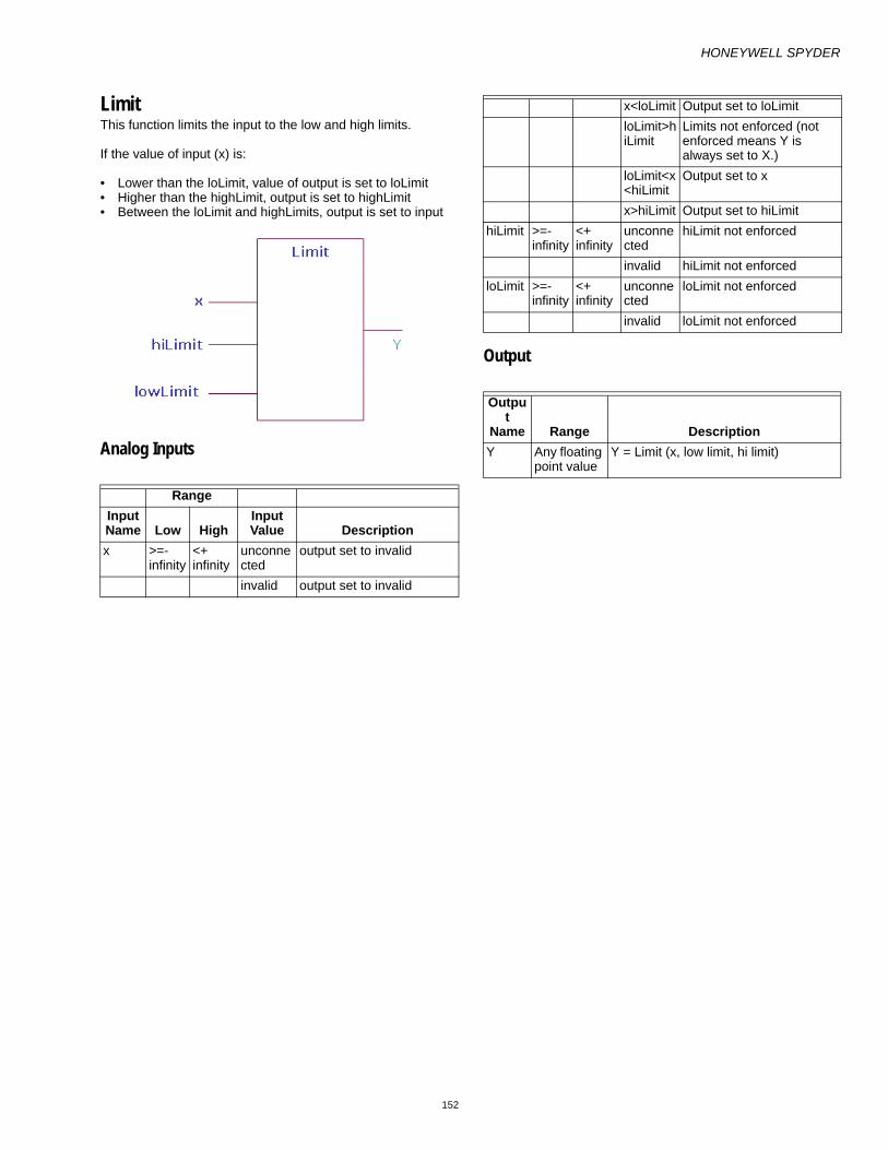
HONEYWELL SPYDER
152
LimitThis function limits the input to the low and high limits.
If the value of input (x) is:
• Lower than the loLimit, value of output is set to loLimit• Higher than the highLimit, output is set to highLimit• Between the loLimit and highLimits, output is set to input
Analog Inputs
Output
RangeInput Name Low High
Input Value Description
x >=- infinity
<+ infinity
unconnected
output set to invalid
invalid output set to invalid
x<loLimit Output set to loLimitloLimit>hiLimit
Limits not enforced (not enforced means Y is always set to X.)
loLimit<x<hiLimit
Output set to x
x>hiLimit Output set to hiLimithiLimit >=-
infinity<+ infinity
unconnected
hiLimit not enforced
invalid hiLimit not enforcedloLimit >=-
infinity<+ infinity
unconnected
loLimit not enforced
invalid loLimit not enforced
Output
Name Range DescriptionY Any floating
point valueY = Limit (x, low limit, hi limit)

HONEYWELL SPYDER
153
MultiplyThis function multiplies one input with the other. y = x1 multiplied by x2. If the result overflows the range of a single precision floating point number (approximately minus 3.4e38 to plus 3.4e38), the result returned is invalid.
NOTE: You can connect both Analog and Digital inputs as inputs to this function block.
Ignore invalid inputs: Select this option if you want the function block to ignore any invalid inputs, if any, and consider only the valid inputs to calculate the output. If this option is left unselected, the invalid inputs will make the output also as invalid. This option is not supported in the PVL6436A, PVL6438N, or PUL6438 models and therefore you cannot download this configuration to those models.
Analog Inputs
Output
RangeInput Name Low High
Input Value Description
x1, x2 >=- infinity
<+ infinity
unconnected
Unconnected inputs are set to 0If all inputs unconnected, output is set to zero
invalid If any input is invalid then output is invalid
Output Name Range Description
Y Any floating point value
Y= x1 * x2

HONEYWELL SPYDER
154
RatioThis function converts the input X to the output Y based on the line defined by x1, y1, x2, and y2.
Output (Y) = y1 + (((x - x1) * (y2 - y1)) / (x2 - x1))
Analog Inputs
Output
Setpoints
RangeInput Name Low High
Input Value Description
x >=- infinity
<+ infinity
unconnected
output set to invalid
invalid output set to invalid
x1-2 >=- infinity
<+ infinity
unconnected
output set to invalid
invalid output set to invalidx1=x2 output set to y1
y1-2 >=- infinity
<+ infinity
unconnected
output set to invalid
invalid output set to invalid
Output
Name Range DescriptionOUTPUT
Any floating point value
Out Ratio(X, X1,Y1, X2,Y2)
Output Name Range/Value Description
operation
• Unlimited• Vav_Flow_Bal
ance• Endpoint_Limit
ed

HONEYWELL SPYDER
155
UnlimitedThe Output is based on the line defined by x1, x2, y1, y2. The behavior of the function block is as illustrated.
Y = y1 + (((x - x1) * (y2 - y1)) / (x2 - x1))
VAV Flow BalanceThe Output is based on the line defined by x1, x2, y1, y2. The slope of the line is as shown in the illustration below.
When x >= x1
Y = y1 + (((y2 – y1) (x2 – x1)) / (x2 – x1))
When x < x1
Y = x
Endpoint LimitedThe Output is based on the line defined by x1, x2, y1, y2. The slope of the line is as shown in the illustration below. Beyond points x1 and x2, the output is limited to the points y1 and y2 respectively. The Output is held between the points y1 and y2.
When x1 < x < x2
Y = y1 + (((y2 – y1) (x2 – x1)) / (x2 – x1))
When x >= x1
Y = y2
When x <= x1
Y = y1

HONEYWELL SPYDER
156
ResetThis function computes the reset value based on the relation of the input to the reset parameters.
Analog Inputs
Output
RangeInput Name Low High Input Value Description
input >=- infinity <+ infinity unconnected output set to invalidinvalid output set to invalid
sensor >=- infinity <+ infinity unconnected output set to invalidinvalid output = input
zeroPctResetVal >=- infinity <+ infinity unconnected output set to invalidinvalid output = input 0%RV = 100%RV output set to input
hundredPctResetVal >=- infinity <+ infinity unconnected output set to invalidinvalid output = input 0%RV = 100%RV output set to input
resetAmount >=- infinity <+ infinity unconnected output set to invalidinvalid output = input
Output Name Range DescriptionOUTPUT Any floating point value Y = Reset (input, sensor, 0%, 100%, reset amount)

HONEYWELL SPYDER
157
Working
If Input Condition is Output• input is unconnected• input is invalid• sensor is unconnected• zeroPctResetVal is unconnected• hundredPctResetVal is unconnected• resetAmount is unconnected
Output = invalid
• sensor is invalid• sensor < zeroPctResetVal• zeroPctResetVal is invalid• hundredPctResetVal is invalid• resetAmount is invalid• hundredPctResetVal = zeroPctResetVal
Output = input
• Sensor > hundredPctResetVal Output = input + resetAmount• If none of the above conditions are satisfied Output = input + ((sensor – zeroPctResetVal)/
(hundredPctResetVal - zeroPctResetVal))*resetAmount

HONEYWELL SPYDER
158
Square RootThis function takes the square root of the input. The Output Y is the Sqrt (X), where X is the input. The behavior of a negative X input is controlled by the parameter negInvalid.
NOTE: Negative values are treated as absolute values. Example: Square root of -9801 is given as 99, taking the absolute value of -9801 as 9801.
Analog Inputs
Output
RangeInput Name Low High
Input Value Description
x >=- infinity
<+ infinity
unconnected
Y= 0
invalid output set to invalid
x1 < 0 See negInvalid descriptionnegInvalid
0 1 0 1
Use the square root of the absolute value.If the input is negative the output is invalid.The default value is 0.
unconnected
Y = sqrt(X), output is invalid for neg x1
invalid Y = sqrt(X), output is invalid for neg x1
Output Name Range Description
Y Any floating point value
Y= Sqrt (X)

HONEYWELL SPYDER
159
SubtractThis function subtracts one input from the other. Y = x1 – x2. If the result overflows the range of a single precision floating point number, (approximately minus 3.4e38 to plus 3.4e38) the result returned is invalid.
NOTE: You can connect both Analog and Digital inputs as inputs to this function block.
Ignore invalid inputs: Select this option if you want the function block to ignore any invalid inputs, if any, and consider only the valid inputs to calculate the output. If this option is left unselected, the invalid inputs will make the output also as invalid. This option is not supported in the PVL6436A, PVL6438N, or PUL6438 models and therefore you cannot download this configuration to those models.
Analog Inputs
Output
RangeInput Name Low High
Input Value Description
x1, x2 >=- infinity
<+ infinity
unconnected
Unconnected inputs are set to 0if all inputs unconnected, y is set to 0
invalid If any input is invalid, y is invalid
Output
Name Range DescriptionY Any floating
point valueY= x1 - x2

HONEYWELL SPYDER
160
ZONE ARBITRATION FUNCTION BLOCKSThe Honeywell SpyderTool provides the following Zone Arbitration function blocks that you can configure and use to build your application logic:
• General Set Point Calculator• Occupancy Arbitrator• Set Temperature Mode• Temperature Set Point Calculator
General Set Point CalculatorThis function does generic setpoint calculation, including reset. It uses the three configuration parameters, effective occupancy, current state, and reset input to calculate the effective setpoint.
Analog Inputs
RangeInput Name Low High Input Value Description
effOccuCurrentState 0 3 unconnected Eff Occ Current state = 0 (OCC)invalid Eff Occ Current state = 0 (OCC)VAL < low Eff Occ Current state = 0 (OCC)VAL > high Eff Occ Current state = 0 (OCC)
ResetInput >=- infinity <+ infinity unconnected Reset Input = Invalidinvalid Reset Input = InvalidVAL < low Reset Input = InvalidVAL > high Reset Input = Invalid
Reset0Pct >=- infinity <+ infinity unconnected Reset 0Pct = Invalidinvalid Reset 0Pct = InvalidVal < low Reset 0Pct = InvalidVal > high Reset 0Pct = Invalid
Reset100Pct >=- infinity <+ infinity unconnected Reset 100Pct = Invalidinvalid Reset 100Pct = InvalidVal < low Reset 100Pct = InvalidVal > high Reset 100Pct = Invalid
ResetAmount >=- infinity <+ infinity unconnected Reset Amount = Invalidinvalid Reset Amount = InvalidVal < low Reset Amount = InvalidVal > high Reset Amount = Invalid
OccupiedSetpoint >=- infinity <+ infinity unconnected Occupied Setpoint = Invalidinvalid Occupied Setpoint = InvalidVal < low Occupied Setpoint = InvalidVal > high Occupied Setpoint = Invalid
StandbySetpoint >=- infinity <+ infinity unconnected Standby Setpoint = Invalidinvalid Standby Setpoint = InvalidVal < low Standby Setpoint = InvalidVal > high Standby Setpoint = Invalid

HONEYWELL SPYDER
161
• Occ = 0• Unocc=1• Bypass =2• Standby = 3• Null = 255 Output
ResetReset allows you to change the Effective Setpoint either in the direction of increased energy savings or in the direction of increased comfort. The Reset Amount (+/-) is positive or negative to accommodate energy savings versus comfort. The reset value varies between zero and the Reset Amount and is proportional to the Reset Input with respect to the Reset 0% and Reset 100% parameters.
NOTE: Insure that the Reset 0% and Reset 100% parame-ters are in the same engineering unit as the Reset Input. The Reset Amount should be in the same units as the configured setpoints.
Positive reset values are added to the setpoint and negative resets are subtracted. Reset only applies in the occupied mode. Reset 0% can be any relation to Reset 100%. The following illustration shows Reset 0% less than Reset 100% with a positive reset Amount. If the any of the Reset Input, Reset 0%, Reset 100% or Reset Amount parameters are invalid, the reset value is set to zero (0). Reset Calculation: Positive amount 0% < 100%
UnoccupiedSetpoint >=- infinity <+ infinity unconnected Unoccupied Setpoint = Invalidinvalid Unoccupied Setpoint = InvalidVal < low Unoccupied Setpoint = InvalidVal > high Unoccupied Setpoint = Invalid
Output Name Range DescriptionEFF_SETPT Any floating point number Effective Setpoint

HONEYWELL SPYDER
162
Reset Calculation: Positive amount 100% < 0%
Eff Occ Current State
Effective Occupancy Current State comes from a scheduler. The valid values are
• Occupied• Unoccupied• Bypass• Standby• NullThe General Setpoint Calculator uses the three configured setpoints: effective occupancy, current state, and Reset Input to determine the effective setpoint. If a setpoint is invalid, INVALID will be propagated to the output as appropriate.
Eff Occ Current State Eff Setpoint
UNOCC Result = unoccupied setpointSTANDBY Result = standby setpointOCC Result = occupied setpoint + resetBYPASS Result = occupied setpoint + resetNULL Result = occupied setpoint + reset

HONEYWELL SPYDER
163
Occupancy ArbitratorThis function computes the current Effective Occupancy Current State and the Manual Override State.
Inputs
• Occ = 0• Unocc=1• Bypass =2• Standby = 3• Null = 255
Outputs
Configuration Specify Net wins (0) or Last in wins (1).
Specify the occupancy sensor operation. There are 3 choices: Conference room (0), Unoccupied Cleaning Crew (1), and Unoccupied Tenant (2).
RangeInput Name Low High Input Value Description
scheduleCurrentState 0 1,3,255 unconnected Schedule Current State = 255 (OCCNUL)invalid Schedule Current State = 255 (OCCNUL)VAL < low Schedule Current State =0 (OCC)VAL > high Schedule Current State = 255 (OCCNUL)
WMOverride 0 1-3,255 unconnected WM Override = 255 (OCCNUL)invalid WM Override = 255 (OCCNUL)VAL < low WM Override = 0 (OCC)VAL > high WM Override = 255 (OCCNUL)
NetworkManOcc 0 1-3,255 unconnected Network Man Occ = 255 (OCCNUL)invalid Network Man Occ = 255 (OCCNUL)VAL < low Network Man Occ = 0 (OCC)VAL > high Network Man Occ = 255 (OCCNUL)
OccSensorState 0 1, 255 unconnected Occ Sensor State = 255 (OCCNUL)invalid Occ Sensor State = 255 (OCCNUL)VAL < low Occ Sensor State = 0 (OCC)VAL > high Occ Sensor State = 255 (OCCNUL)
Output Name Range DescriptionEFF_OCC_CURRENT_STATE
0 to 3 (Occupied, Unoccupied, Bypass, Standby)
Effective Occupancy Current state
MANUAL_OVERRIDE_STATE
0 to 3, 255 (Occupied, Unoccupied, Bypass, Standby, Null)
Manual Override State
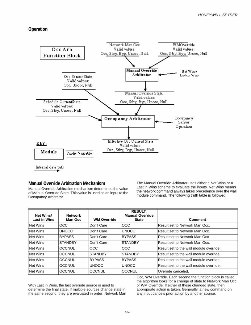
HONEYWELL SPYDER
164
Operation
Manual Override Arbitration MechanismManual Override Arbitration mechanism determines the value of Manual Override State. This value is used as an input to the Occupancy Arbitrator.
The Manual Override Arbitrator uses either a Net Wins or a Last in Wins scheme to evaluate the inputs. Net Wins means the network command always takes precedence over the wall module command. The following truth table is followed.
With Last in Wins, the last override source is used to determine the final state. If multiple sources change state in the same second, they are evaluated in order: Network Man
Occ, WM Override. Each second the function block is called, the algorithm looks for a change of state to Network Man Occ or WM Override. If either of these changed state, then appropriate action is taken. Generally, a new command on any input cancels prior action by another source.
Net Wins/Last in Wins
NetworkMan Occ WM Override
RESULT:Manual Override
State CommentNet Wins OCC Don’t Care OCC Result set to Network Man Occ.Net Wins UNOCC Don’t Care UNOCC Result set to Network Man Occ.Net Wins BYPASS Don’t Care BYPASS Result set to Network Man Occ.Net Wins STANDBY Don’t Care STANDBY Result set to Network Man Occ.Net Wins OCCNUL OCC OCC Result set to the wall module override.Net Wins OCCNUL STANDBY STANDBY Result set to the wall module override.Net Wins OCCNUL BYPASS BYPASS Result set to the wall module override.Net Wins OCCNUL UNOCC UNOCC Result set to the wall module override.Net Wins OCCNUL OCCNUL OCCNUL Override canceled.

HONEYWELL SPYDER
165
NOTE: Any other input value not listed, is not a valid state. If received, it is treated as OCCNUL.
NOTE: For last in wins, the value in the table was just changed from another state and this is the current state.
This function block doesn’t have the ability to trigger on a network variable update. This differs from E-Bus Mechanisms which state the node should do the bypass timing for the network Manual Occupancy Command and reload the timer when a BYPASS update occurs.
From iteration to iteration of the Function Block, the Occupancy Arbitrator keeps track of the last state of the Network Man Occ and WM Override inputs so that it knows when a transition occurs. On power up/reset the last latch value is set to FALSE, regardless of the negation configuration. Override is canceled after a power outage. The Network Man Occ and WM Override inputs must reassert themselves after a power outage.
Network Manual Occupancy Input
Network Man Occ is a method to command the occupancy state from a network workstation or a node. The user may write logic to combine these if both are required for the application. Network Man Occ can command the state to be occupied, unoccupied, standby, bypass or null. It is required that the workstation (nviManOccCmd) or network node (nviBypass) perform any timing needed (i.e. bypass).
WM Override Input
WM Override is a method to command the occupancy state from a locally wired wall module. WM Override can command the state to be occupied, unoccupied, standby, bypass or null. It is required the function block wired to this input perform any timing needed (i.e. bypass). Note: the current T7770 wall module function doesn’t support occupied or standby override, but future wall modules might.
Occupancy Arbitration Mechanism
The Occupancy Arbitrator computes the effective occupancy status. The inputs of the Effective Occupancy Arbitrator include the Schedule Current State, Occ Sensor State, and Manual Override State. The Manual Override State comes from above.
The Effective Occupancy Arbitrator sets the Effective Occ Current State. Valid states of current state are:
• OCC: The space is occupied.• UNOCC: The space is unoccupied.• BYPASS: The space is occupied, though it is not
scheduled to be occupied.• STANDBY: The space is in a standby state, somewhere
between occupied and unoccupied.OCCNUL is not a valid output. If all inputs are OCCNUL, the output will be set to occupied.
Net Wins/Last in Wins
NetworkMan Occ(note2)
WM Override(note 2)
RESULT:Manual Override
State CommentLast in Wins OCC Don’t Care OCC Result set to Network Man Occ.Last in Wins UNOCC Don’t Care UNOCC Result set to Network Man Occ.Last in Wins BYPASS Don’t Care BYPASS Result set to Network Man Occ.Last in Wins STANDBY Don’t Care STANDBY Result set to Network Man Occ.Last in Wins OCCNUL Don’t Care OCCNUL Override canceled.Last in Wins Don’t Care OCC OCC Result set to the wall module override.Last in Wins Don’t Care STANDBY STANDBY Result set to the wall module override.Last in Wins Don’t Care BYPASS BYPASS Result set to the wall module override.Last in Wins Don’t Care UNOCC UNOCC Result set to the wall module override.Last in Wins Don’t Care OCCNUL OCCNUL Override canceled.

HONEYWELL SPYDER
166
Manual Override
State
ScheduleCurrent
State
OccSensorState
Occ Sensor Operation
RESULT:effOcc
CurrentState Comments
Follows LonMark
SCCOCC Don’t Care Don’t Care Don’t Care OCC Result = Manual Override
StateYes
STANDBY Don’t Care Don’t Care Don’t Care STANDBY Result = Manual Override State
Yes
UNOCC Don’t Care Don’t Care Don’t Care UNOCC Result = Manual Override State
Yes
BYPASS OCC Don’t Care Don’t Care OCC Result stays at occupied because bypass isn’t effective when scheduled for occupied.
Yes
BYPASS STANDBY Don’t Care Don’t Care BYPASS Result stays at bypass. YesBYPASS UNOCC Don’t Care Don’t Care BYPASS Result = bypass YesBYPASS OCCNUL OCC Don’t Care OCC Result follows occupancy
sensorYes
BYPASS OCCNUL UNOCC Don’t Care BYPASS Result follows manual override
Yes
BYPASS OCCNUL OCCNUL Don’t Care OCC When occupancy sensor is null, default to occupied.
Yes
OCCNUL STANDBY Don’t Care Don’t Care STANDBY Result = scheduled state. YesOCCNUL OCC OCC Don’t Care OCC All say we’re Occupied. YesOCCNUL OCC UNOCC Don’t Care STANDBY We’re schedule to be
occupied but room is actually unoccupied, so go to standby to save energy.
Yes
OCCNUL OCC OCCNUL Don’t Care OCC Sensor not present so use schedule.
Yes
OCCNUL UNOCC UNOCC Don’t Care UNOCC All say we’re unoccupied. YesOCCNUL UNOCC OCCNUL Don’t Care UNOCC Sensor not present so use
scheduleYes
OCCNUL OCCNUL OCC Don’t Care OCC Result -= occupancy sensor state.
Yes
OCCNUL OCCNUL UNOCC Don’t Care UNOCC Result -= occupancy sensor state.
Yes
OCCNUL OCCNUL OCCNUL Don’t Care OCC Result = occupied because the LonMark SCC sets a null occupancy sensor to Occupied.
Yes
OCCNUL UNOCC OCC Conference Room
UNOCC Stay unoccupied regardless of what the sensor says (i.e. save energy).
Yes
OCCNUL UNOCC OCC Cleaning Crew STANDBY We’re schedule to be unoccupied but the room is actually occupied, so go to standby for the comfort of the cleaning crew.
No
OCCNUL UNOCC OCC Tenent OCC We’re schedule to be unoccupied but the room is actually occupied, so go to occupied for the comfort of the tenant.
No

HONEYWELL SPYDER
167
Set Temperature ModeThis function automatically calculates the effective temperature control mode based on the control type, system switch setting, network mode command, temperature set points, supply temperature and space temperature. From iteration to iteration, the Function Block keeps track of the previous command mode and the effective temperature mode. On power up/reset, these are cleared.
effTempMode indicates the current Mode determined by input states and arbitrated by control logic. SetTempMode does not generate all the possible Modes available. The valid enumerated values have the following meanings:
Analog Inputs
effTempMode MeaningCOOL_MODE=0 Cool air is being supplied to the node via the central air supply and cooling energy is
being supplied to the controlled space. REHEAT_MODE=1 Cool air is being supplied to the node via the central air supply. The air is being
reheated by a local Heat source.HEAT_MODE=2 Heated air is being supplied to the node via the central air supply and heated air is
being supplied to the controlled space. EMERG_HEAT=3 Emergency Heat is being supplied to the node via the central air supply.OFF_MODE=255 Controller is commanded off.
RangeInput Name Cfg Low High Input Value Description
sysSwitch IN 0 255 unconnected SystemSwitch = SS_AUTO(0)invalid SystemSwitch = SS_AUTO(0)VAL < low SystemSwitch = SS_AUTO(0)VAL > high SystemSwitch = SS_AUTO(0)
cmdMode IN 0 255 unconnected val = CMD_AUTO_MODE(0)invalid val = CMD_AUTO_MODE(0)VAL < low val = CMD_AUTO_MODE(0)VAL > high val = CMD_AUTO_MODE(0)
supplyTemp IN 0 255 unconnected SupplyTemp = invalidinvalid SupplyTemp = invalidVal < low SupplyTemp = lowVal > high SupplyTemp = high
spaceTemp IN 0 255 unconnected SpaceTemp = invalidinvalid SpaceTemp = invalidVal < low SpaceTemp = lowVal > high SpaceTemp = high
effHeatSP IN >=- <+ unconnected EffHeatSp = 68

HONEYWELL SPYDER
168
Outputs
ConfigurationSpecify the control Type (controlType)
• 0 – CVAHU• 1 – VAV
Input Enumerations
The CVAHU arbitration logic for ControlType = 0 (CVAHU) is summarized by the table below:
invalid EffHeatSp = 68effCoolSP IN >=- <+ unconnected EffCoolSp = 75
invalid EffCoolSp = 75allowAutoChange IN_PAR 0 1 unconnected allowAutoChange=1
invalid allowAutoChange=1Val < low allowAutoChange=1Val > high allowAutoChange=1
RangeOutput Name Cfg Low High Description
EFF_SETPT OUT_FLT 0.0 255.0 If effTempMode=COOL_MODE then val= effCoolSetPt, else val=effHeatSetPt
EFF_TEMP_MODE
OUT_DIG 0 255 See arbitration table for VAV and CVAHU behavior
sysSwitchSS_AUTO = 0SS_COOL = 1SS_HEAT = 2SS_EMERG_HEAT = 3SS_OFF = 255
cmdModeCMD_AUTO_MODE = 0 = 0CMD_HEAT_MODE = 1 = 1CMD_COOL_MODE = 2 = 2CMD_OFF_MODE = 3 = 3CMD_EMERG_HEAT_MODE = 4 = 4CMD_NUL_MODE = 255 = 255
Space Temp sysSwitch cmdMode effTempModeX X CMD_OFF(3) OFF_MODE(255)X X CMD_EMERG_HEAT_MODE(4) EMERG_HEAT(3)X X CMD_COOL_MODE(2) COOL_MODE(0)X X CMD_HEAT_MODE(1) HEAT_MODE(2)X X ENUMERATION (5) through
ENUMERATION (254) HEAT_MODE(2)
X SS_COOL (1) CMD_AUTO_MODE(0), CMD_NUL_MODE(255) COOL_MODE (0)

HONEYWELL SPYDER
169
X means Don’t Care
NOTE: If allowAutoChange = 1 then allow to switch between HEAT_MODE and COOL_MODE. Must have valid effHeatSP and effCoolSP. If allowAutoChange = 1 and effHeatSp > effCoolSp, then effHeatSp will be internally set to effCoolSP.
The VAV Mode arbitration logic for controlType = 1 (VAV) is summarized by the table below:
X SS_HEAT (2)or ENUMERATION(4) through ENUMERATION (254)
CMD_AUTO_MODE(0), CMD_NUL_MODE(255) HEAT_MODE(2)
X SS_EMERGENCY_HEAT(3) CMD_AUTO_MODE(0), CMD_NUL_MODE(255), EMERG_HEAT(3)X SS_OFF (255) CMD_AUTO_MODE(0), CMD_NUL_MODE(255) OFF_MODE(255)INVALID SS_AUTO(0), invalid,
unconnected, or a non-listed enumeration.
CMD_AUTO_MODE(0), CMD_NUL_MODE(255) HEAT_MODE(2)
VALID SS_AUTO(0), invalid, unconnected, or a non-listed enumeration.
CMD_AUTO_MODE(0), CMD_NUL_MODE(255), COOL_MODE(0) or HEAT_MODE(2)(see following note)
Space Temp sysSwitch Supply Temp cmdMode effTempMode
X X X CMD_OFF_MODE(3) OFF_MODE(255)X X X CMD_EMERG_HEAT_MODE(4) HEAT_MODE(2)X X X ENUMERATION (5) through
ENUMERATION (254) COOL_MODE(0)
Valid X <70.0 CMD_AUTO_MODE (0), CMD_HEAT_MODE (1), CMD_NUL_MODE (255)
COOL_MODE (0) or REHEAT_MODE (1)(see note 1)
Valid X <70.0 CMD_COOL_MODE(2) COOL_MODE (0) Valid X 70.0 TO 75.0 CMD_AUTO_MODE (0),
CMD_HEAT_MODE (1), CMD_COOL_MODE (2), CMD_NUL_MODE (255)
COOL_MODE (0), REHEAT_MODE (1), HEAT_MODE (2) (see note 1 for transition between cool mode and reheat mode)
Valid X >75 CMD_AUTO_MODE (0), CMD_HEAT_MODE (1), CMD_NUL_MODE (255)
HEAT_MODE(2)
Valid X Invalid or unconnected
CMD_HEAT_MODE (1) HEAT_MODE (2)
Valid X Invalid or unconnected
CMD_COOL_MODE (2) COOL_MODE (0)
Valid SS_COOL(1) Invalid or unconnected
CMD_AUTO_MODE (0), CMD_NUL_MODE (255)
COOL_MODE(0)
Valid SS_HEAT(2) Invalid or unconnected
CMD_AUTO_MODE (0), CMD_NUL_MODE (255)
HEAT_MODE(2)

HONEYWELL SPYDER
170
X means Don’t Care
NOTE: If allowAutoChange = 1 then allow to switch between REHEAT_MODE and COOL_MODE. Must have valid effHeatSP and effCoolSP.
If in cool mode and spacetemp < effheat setpt and space temp < effcoolsetpt – 1.0 then go to reheat mode. If in reheat mode and spacetemp > effCoolSetpt and spacetemp > effHeatsetpt + 1.0 then go to cool mode.
Valid SS_EMERGENCY_HEAT(3)
Invalid or unconnected
CMD_AUTO_MODE (0), CMD_NUL_MODE (255)
HEAT_MODE(2)
Valid SS_OFF(255) Invalid or unconnected
CMD_AUTO_MODE (0), CMD_NUL_MODE (255)
OFF_MODE(255)
Valid SS_AUTO(0), invalid, unconnected, or a non-listed enumeration.
Invalid or unconnected
CMD_AUTO_MODE (0), CMD_NUL_MODE (255),
COOL_MODE(0) or REHEAT_MODE(1) (see note 1)
InValid SS_AUTO(0), invalid, unconnected, or a non-listed enumeration.
Invalid or unconnected
CMD_AUTO_MODE (0), CMD_NUL_MODE (255),
COOL_MODE(0)

HONEYWELL SPYDER
171
Temperature Set Point CalculatorThis function calculates the current Effective Heat setpoint and Effective Cool setpoint based on the current schedule information, occupancy override, and intelligent recovery information.
Inputs
• Occ = 0• Unocc=1• Bypass =2
• Standby = 3• Null = 255
RangeInput Name Low High Input Value Description
EffOccCurrentState 0 3 unconnected Eff Occ Current State = 0 (OCC)invalid Eff Occ Current State = 0 (OCC)VAL < low Eff Occ Current State = 0 (OCC)VAL > high Eff Occ Current State = 0 (OCC)
ScheduleNextState 0 1, 3, 255 unconnected Schedule Next State = 255 (OCCNUL)invalid Schedule Next State = 255 (OCCNUL)VAL < low Schedule Next State = 255 (OCCNUL)VAL > high Schedule Next State = 255 (OCCNUL)
ScheduleTUNCOS 0 11520 unconnected Schedule TUNCOS = 11520(min) invalid Schedule TUNCOS = 11520
VAL < low Schedule TUNCOS = 0VAL > high Schedule TUNCOS = 11520
Setpoint >=- <+ unconnected Setpoint = 0invalid Setpoint = 0VAL < low Setpoint = 0VAL > high Setpoint = 0
HeatRampRate 0 <+ unconnected Heat Ramp Rate = 0invalid Heat Ramp Rate = 0VAL < low Heat Ramp Rate = 0VAL > high Heat Ramp Rate = 0
CoolRampRate 0 <+ unconnected Cool Ramp Rate = 0invalid Cool Ramp Rate = 0VAL < low Cool Ramp Rate = 0VAL > high Cool Ramp Rate = 0
ManualOverrideState 0 3,255 unconnected Manual Override State = 255 (OCCNUL)invalid Manual Override State = 255 (OCCNUL)VAL < low Manual Override State = 255 (OCCNUL)VAL > high Manual Override State = 255 (OCCNUL)

HONEYWELL SPYDER
172
Outputs
Configuration• Specify the 6 setpoints. When the TempSPCalc Function
Block is used, nciTempSetpoints (SNVT temp setpt) is added by the Spyder Tool. nciTempSetpoints is mapped by the Tool to the first 6 Public variables under Control non-volatile. The order is:— Occupied Cool— Standby Cool— Unoccupied Cool — Occupied Heat— Standby Heat— Unoccupied Heat
You may have more than one TempSPCalc Function Block, however all blocks use the same nciSetpoints network variable and map to the same 6 public variables. See below for more information.
Output Name Range DescriptionEFF_HEAT_SETPT
Any floating point number
Effective Heat Setpoint
EFF_COOL_SETPT
Any floating point number
Effective Cool Setpoint

HONEYWELL SPYDER
173
Temperature Setpoint Calculator• The Temperature Setpoint Calculator uses the following 6
programmed setpoints to determine the effective heat setpoint and effective cool setpoint:
• Effective occupancy current state• Scheduled next state and TUNCOS• Center/offset setpoint• Manual override state• Recovery heat ramp rate• Recovery cool ramp rateThe algorithm:
• Verifies if inputs are within range.• Computes the occupied and standby heat and cool
setpoints based on the setpoint input and programmed setpoints.— If the effective occupancy current state is in unoccu-
pied mode and not in manual override, then calculates the recovery ramps.
— If the effective occupancy current state is in occupied or bypass mode, uses the occupied setpoints.
— If the effective occupancy current state is in standby mode, uses the standby setpoints.
Programmed Set PointsThe controller is programmed with six setpoints. There are three setpoints of occupied, standby and unoccupied for heating and the same for cooling. All six can be changed from the Network via nciSetpoints. The Temperature Setpoint
calculator does not place any restrictions on relationships between the setpoints and other inputs and the resulting calculations. This function block depends on the Tools writing nciSetpoints to enforce the range and relationship.
For reference, the LonMark Space Comfort Controller profile defines nciSetpoints as having a range of 10 Deg. C to 35 Deg. C with the following relationship unoccupied heat = standby heat = occupied heat = occupied cool = standby cool = unoccupied cool.
Setpoint InputThis input allows the temperature setpoint for the occupied and standby mode to be changed via the wall module and/or network. This input can be either center or offset setpoint. If the input is less than 10, then it is treated as offset setpoint. If the input is greater than or equal to 10, it is treated as center setpoint. It is the user’s responsibility to insure the results are within the desired range. That is, it is possible to combine the setpoint input and the programmed heat and cool setpoints and get an effective setpoint outside of the unoccupied setpoints.
Offset SetpointThe setpoint acts in offset mode (that is, relative setpoint) when the value on the Setpoint input is less than 10. The setpoint input adjusts the programmed occupied and standby heating and cooling setpoints up and down by the amount on the input. The user must insure the input range is less than

HONEYWELL SPYDER
174
+10 for offset setpoint to be used. The setpoint input does not affect the unoccupied setpoints. During bypass, the occupied setpoints are adjusted. If the setpoint input is not connected or the sensor has failed, the offset is zero. You must insure consistent units. That is, if the Setpoint input is in degrees Farenheit, the programmed setpoints should also be in degrees Farenheit.
• Occupied cool setpoint = programmed occupied cool setpoint + Setpoint input.
• Occupied heat setpoint = programmed occupied heat setpoint + Setpoint input.
• Standby cool setpoint = programmed standby cool setpoint + Setpoint input.
• Standby heat setpoint = programmed standby heat setpoint + Setpoint input.
Center SetpointIf the value on the Setpoint input is greater than or equal to 10, it will be used as the center setpoint (that is, absolute setpoint). If an invalid setpoint is on the Setpoint input, then the programmed setpoints will be used. The individual heat/cool setpoints for occupied and standby mode then derive from the Setpoint input minus/plus half the zero energy bands calculated from the programmed setpoints.
Example• zeb occ = programmed occupied cool - programmed
occupied heat• zeb standby = programmed standby cool - programmed
standby heat.• Occupied cool setpoint = setpoint + 1/2 zeb occ• Occupied heat setpoint = setpoint - 1/2 zeb occ• Standby cool setpoint = setpoint + 1/2 zeb standby• Standby heat setpoint = setpoint - 1/2 zeb standby
Manual Override StateThe Manual Override State is required to turn off recovery if in manual mode. If the Manual Override State is any value other than null, then the algorithm does not know the scheduled next state and setpoint recovery is NOT done.
NOTE: Manual Override State does not affect the effective occupancy state. The OccArb function block already handles this. The effective setpoints never go to the state commanded by the Manual Override state input. Manual Override State just affects recovery as stated above.
Effective Occupied StateThis is used by the algorithm to determine the setpoints for the current occupancy state. When the Effective Occupancy Current state is occupied or bypass, use the occupied setpoints. When the Effective Occupancy Current state is standby, use the standby setpoints. When the Effective Occupancy Current state is unoccupied, recover the setpoint to the next state of occupied or standby. No recovery is done if in manual mode. See Adaptive Intelligent Recovery section.
Heating and Cooling Ramp ratesThese are used by the adaptive recovery algorithm to recover the heating and cooling setpoints from their unoccupied values.
Schedule Next state and TUNCOSThese are used by the adaptive recovery algorithm to recover the heating and cooling setpoints from their unoccupied values.
Adaptive Intelligent RecoverySet point recovery applies to setpoint changes associated with the following schedule state changes:
• Unoccupied to Standby• Unoccupied to OccupiedSetpoint changes from occupied or standby to unoccupied state, changes from occupied to standby state, and changes from standby to occupied state use a step change in setpoint.
The heating or cooling recovery ramp begins before the next state transition time.
During the recovery ramps, the heating and cooling set points are ramped from the unoccupied setpoint to the next state setpoint. The setpoint ramps will be at the target setpoint 10 minutes prior to the occupied/standby event time.
This allows the HVAC equipment an extra 10 minutes to get the space temperature to the target setpoint during recovery.
NOTE: Recovery is NOT done if manual occupancy is in effect.
You provide the heat and cool recovery ramp rates to the Temperature Setpoint Calculator. These can be constants, values calculated using the Ratio function block using outdoor air temperature, or some other method.
Heating and cooling recovery ramp rates can be any value greater than or equal to zero and have units of degree/Hr. A ramp rate of 0 degree/Hr means no recovery ramp for that

HONEYWELL SPYDER
175
mode. This means the setpoint steps from one setpoint to the other at the event time. (that is, No extra 10 minutes). The user must insure consistent units. That is, the ramp rates should be in the same units as the setpoints.
Note: If the user programs a rate of 1 degree/Hr and has more than 192 degree spread between OCC and UNOCC set points, the algorithm will be in recovery immediately when going to UNOCC. This is because the maximum TUNCOS is 11520 minutes times 1 degree/Hr = 192 degree maximum delta.
TUNCOS MesaThe controller implements the TUNCOS Mesa feature. This feature, also known as the Smith Mesa after Gary Smith implemented it in the T7300 series 1000. The TUNCOS Mesa was added to the algorithm to insure the HVAC equipment gets the space temperature up to setpoint by the occupied time. The recovery algorithm subtracts 10 minutes from the TUNCOS and uses that to calculate the setpoint ramps.
Effective Setpoint LimitingThis algorithm does nothing to insure the effective cooling setpoint does not go above the unoccupied cooling setpoint and the effective heating setpoint does not go below the unoccupied heating setpoint. No check is made to insure the effective heat and cool setpoints stay a minimum distance apart.

HONEYWELL SPYDER
176
PASS THRUUse this utility to provide input to multiple slots in one go.
Example: Assume we have an Application called Application1. This has a function block Add inside it. Now, you want to give inputs to all slots of the Add block in one go from an NV or Object outside Application1. To achieve this, you can expose all slots of the Add block using the Composite feature and then connect the NV or Object to each slot.
Alternatively, you can drag a Pass Thru component from the Honeywell Spyder Palette (Util > Pass Thru) to Application1. Now, you can expose the Pass slot using the Composite feature and then connect this slot to the NV/Object. Double-click Application1 and connect Pass slot to as many slots on the Add block as you want.

HONEYWELL SPYDER
177
CALIBRATE SENSORS
Pre-requisites• The application logic is opened in Niagara Workbench and
the same is downloaded to the Controller.• The Controller should be online.
ProcedureThe Sensor Calibration screen allows the user to calibrate the sensor. This option is available only for commissioned and downloaded controllers.
1. Right click the controller name on the Nav palette. Select Calibrate Sensor. The Sensor Calibration dia-log box opens.
2. Enter the value the sensor must detect in the Edit Value field.
3. Click Close to close the dialog box.
NOTE: If no sensors are configured, a warning message, 'No sensors configured' appears. If a Modulating input is configured as Counter/Pulse Meter it will not be shown up in this screen.
Name DefinitionName Shows all the Modulating Inputs configured in the ControlProgram.Sensor Type Shows the actual sensor type configured for that modulating input. This field is non-editable.Actual Value Shows the actual value of the modulating input read by the controller. This field is non-editable. Edit Value Enter the value that the sensor must detect. Offset Shows the difference between the actual and the edit value. This field is non-editable.Calibrate Click Calibrate to calibrate the Modulating Input to the value entered by the user.Refresh Click Refresh to refresh the Modulating Input values.Close Click Close to close the dialog box.

HONEYWELL SPYDER
178
DIAGNOSE OUTPUTSYou can monitor and diagnose the output value of the Lon and Bacnet controllers. If the output is faulty, it can be identified by manually setting the values of the physical points.
Pre requisites• The Controller should be online.• It should be in a commissioned state.The Diagnostic screen displays:
• The Outputs section where outputs can be commanded.• The current sensor values to enable you to watch the effect
of the outputs on various values.• The current mode of the device is displayed.
Diagnose Outputs for a Lon DeviceUsing the Controller Diagnostics feature, you can monitor and diagnose the outputs of a Lon device. By setting the mode from auto to manual, you can edit the values of the modulating and binary outputs to get the required output.
Procedure1. Right click on the controller. Select Controller Diag-
nostics. The Diagnostics dialog box appears.2. Enter the value the sensor must detect in the Edit Value
field and enter/select information as given in the follow-ing table.
NOTE:
— When an output is set to manual mode, the tool writes to priority 8 of that output.
— If the output is already driven at a higher priority, there is no effect of setting an output in manual mode. In this case, manual mode takes into effect only when priority 1 to priority 7 are relinquished.
3. Click Close to close the dialog box.
Diagnose Outputs for a Bacnet DeviceUsing the Diagnose Outputs feature, you can monitor and diagnose the outputs of a Bacnet device. By setting the mode from auto to manual, you can edit the values of the modulating and binary outputs to get the required output.
Name DefinitionModulating Output The number of Modulating Outputs depends on the outputs configured in the application logic.
Actual Value: Displays the value of the modulating output read by the controller. This field is non-editable.Edit Value: Enter the value that the sensor must be detecting. The range is 0-100 percent.
Binary Output The number of Binary Outputs depends on the outputs configured in the application logic. Actual Value: Displays the value of the modulating output read by the controller. This field is non-editable.Edit Value: Select True or False.
Mode Displays the current mode of the device.Set Click Set to set the controller to manual mode. It writes the configured values to the controller
and automatically puts the modulating output in the manual mode.Refresh Click Refresh to refresh the values.
Close Click Close to close the dialog box. It prompts you to set all inputs in the manual or auto mode.
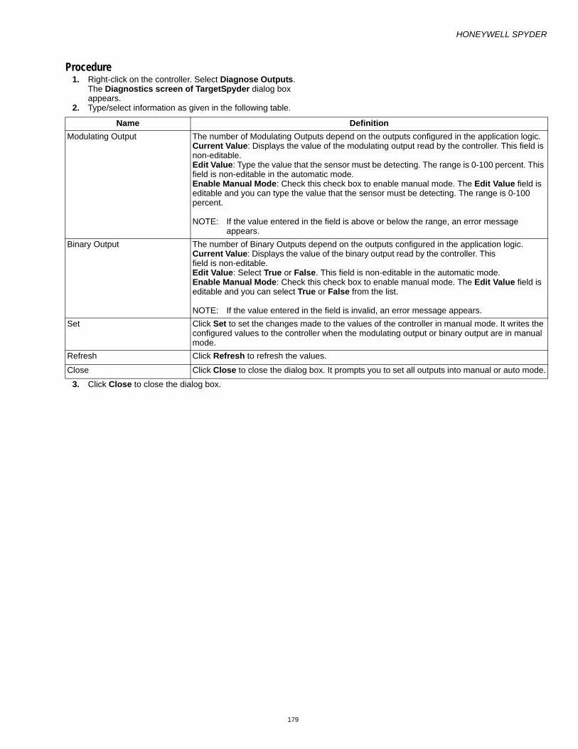
HONEYWELL SPYDER
179
Procedure1. Right-click on the controller. Select Diagnose Outputs.
The Diagnostics screen of TargetSpyder dialog box appears.
2. Type/select information as given in the following table.
3. Click Close to close the dialog box.
Name DefinitionModulating Output The number of Modulating Outputs depend on the outputs configured in the application logic.
Current Value: Displays the value of the modulating output read by the controller. This field is non-editable.Edit Value: Type the value that the sensor must be detecting. The range is 0-100 percent. This field is non-editable in the automatic mode.Enable Manual Mode: Check this check box to enable manual mode. The Edit Value field is editable and you can type the value that the sensor must be detecting. The range is 0-100 percent.
NOTE: If the value entered in the field is above or below the range, an error message appears.
Binary Output The number of Binary Outputs depend on the outputs configured in the application logic.Current Value: Displays the value of the binary output read by the controller. This field is non-editable.Edit Value: Select True or False. This field is non-editable in the automatic mode.Enable Manual Mode: Check this check box to enable manual mode. The Edit Value field is editable and you can select True or False from the list.
NOTE: If the value entered in the field is invalid, an error message appears.Set Click Set to set the changes made to the values of the controller in manual mode. It writes the
configured values to the controller when the modulating output or binary output are in manual mode.
Refresh Click Refresh to refresh the values.
Close Click Close to close the dialog box. It prompts you to set all outputs into manual or auto mode.

HONEYWELL SPYDER
180
MACROSA Macro is a group of functional blocks grouped together that define a specific functionality. Commonly used program elements can be defined as macros so that they could be reused across applications. Macros offer you a way of transporting logic between different devices. They help in segmenting a huge program into smaller logical blocks.
Functional blocks can be grouped as macros and you can include macros under macros. Macros can be re-used in other applications.
You can selectively choose inputs/outputs of the blocks that you have used in a macro need to be exposed in a particular setup. However, this does not limit you from using the same macro elsewhere and choosing a different set of inputs/outputs to expose.
When a macro is created and saved, it can be dragged and dropped on to the wiresheet view and used in creating application logic. The fields of the function blocks that make up a macro become available as fields of the macro itself. Macros are displayed as any other function blocks in a container view.
Macros:
• can contain only functional blocks.• cannot contain I/Os.• cannot contain network variables.• can have a macro within a macro.

HONEYWELL SPYDER
181
SPYDER LIBRARYYou can use a Spyder library to store devices, ControlPrograms, applications, and/or macros. A default library is automatically created at the location <Drive>:/Niagara/AppLib. This library is available when you open the Spyder Library the first time. You cannot close this default library.
You can, however, create your own library to create and store macros, applications, and/or devices. Each library comes with two default folders: Device(s), Application(s) and SBus_WM_Config(s). All the SBusWall modules you add and save are stored in the SBus_WM_Config(s) folder of a library.
All the devices you create and save are stored in the Device(s) folder of a library. All macros and applications you create and save are stored in the Application(s) folder of a library.
Display Spyder Library PaletteTo display the Spyder Library palette on the left side of the window:
• From the Menu bar, select Windows > Side Bars > Spyder Library.
The Spyder Library palette appears on the left side of the screen with the contents of the default library. Every library contains the default folders: Device(s), Application(s) and SBus_WM_Config(s). The application libraries present in the default parent folder path are displayed in the dropdown list.
To change the current parent folder path:
1. Click the options button on the library palette to get a drop-down list and select Select Parent Path. The Advance Options dialog box appears.
2. Click the browse button on the right side of the Advance Options dialog box. The Directory Chooser dialog box appears.
3. Browse through to the location where you have stored your library files and click Choose.
4. Select the Save as default parent path option if you want to make this folder the default folder for future use.The libraries available in the default parent folder path are displayed when the workbench is restarted. On subsequent uses, the libraries available in the last selected parent folder path are listed. Even while uploading items, the default library path is invoked.
5. Click OK. The drop-down list box in the Spyder palette then displays the application libraries in the selected folder. If you select an application library from the drop-down list box, all the devices and applications present in that library in the tree is displayed in the sidebar.
NOTE: The parent folder path selected in a workbench is not applicable when the library is opened from a browser. The parent folder selected in the browser is applicable only when the library is opened from a browser and is not reflected when the library is opened from a workbench.
Close Spyder Library PaletteClick the down arrow on the menu bar of the Spyder Library palette and click Close to close the library palette.

HONEYWELL SPYDER
182
Open Spyder LibraryMacros, Applications and Devices that you create can be stored in a library for being reused in another project or scenario. You can create libraries based on your requirement and store them. You can then import selected items of libraries in the station (in LonNetwork or Device Logic). .
There is a default library shipped by Honeywell. However, you can create and save your own libraries containing macros, applications and or devices. Such user defined libraries can be modified, saved and shared across projects or across users.
To open a user-created library:
1. Click the options button on the library palette to get a
drop-down list and select Select Parent Path.
The Advance Options dialog box appears.
2. Click the browse button on the right side of the Advance Options dialog box and select a destination folder where the library you have stored is located. The Directory Chooser dialog box appears.
3. Browse through to the location where you have stored your library files and select Choose.
4. Select the Save as default parent path option if you want to make this folder the default folder for future use.The libraries available in the default parent folder path are displayed when workbench is restarted. On subsequent uses, the libraries available in the last selected parent folder path are listed. .
5. The contents of the library are displayed in the library palette. Also, the path where the library files are stored is also displayed in the library palette.
NOTE: If you have multiple libraries stored at a location, use the down arrow next to the field displaying the library path and select the library you want to open.
— The parent folder path selected in a workbench is not applicable when the library is opened from a browser. The parent folder selected in the browser is applicable only when the library is opened from a browser and is not reflected when the library is opened from a work-bench.
Close Spyder LibraryClick the button on the library palette (as shown below) and click Close Library to close the library.
NOTE: The default library cannot be closed.
Add Items to Spyder LibraryYou can add devices, macros, Sbus wall modules and/or applications to a library.
Add New Item to Library
From the Spyder Library PaletteTo add a new Macro, Device, SbusWallModule, ControlProgram, or Application to a library:
1. Open the Library in which you want to add the new application logic.
2. Click the options button on the library palette to get a drop-down list and select New > Application/LonDe-vice/BacnetDevice/Macro/SBusWallModule.

HONEYWELL SPYDER
183
3. The App/LonDevice/BacnetDevice/Macro/SBusWallModule Name dialog box appears.
4. Type a name for the item and click OK. The new item is added to the library in the Application(s) folder of the library in case of macros and applications and to the Device(s) folder in case of in case of Lon and Bacnet devices and displayed in the library palette.
From the Nav PaletteTo add a new Macro, Device, Application, ControlProgram, or SBusWallModule to a library:
1. Right-click the device, macro, application, ControlPro-gram, or SBusWallModule in the Nav palette and select Save to Library. The Save Library Item dialog box appears.
NOTE: Note: The Library list displays all libraries in the Par-ent folder. The Parent folder is indicated by the Par-ent Folder Path. The Save to Library function is possible only in the Engineering mode and applies to macros, applica-tions, devices, SBusWallModules, and control pro-grams.
2. You have options to: Save as New App: If you are adding this item for the first time to a library, this is the only option available. If not saving an item for the first time, this option creates a new item in the specified library. or Overwrite App (New Version): If you are adding an item for the first time to a library, this option is disabled. If not saving an item for the first time, this option over-writes the existing item and increments the version number.
3. Select the library to which you want to save this item from the Library list and proceed to step 6 of this proce-dure.
4. Alternatively, if you want to create a new library and save the changes in the newly created library, click the + button. The Library Name dialog box appears.
5. Enter the name of the library and click OK. The location where the new library is saved is displayed in the Par-ent Folder Path. The default location is <Drive>:\Nia-gara. If you want to change the location, click Advanced Settings to display the Advanced Options dialog box.
6. Click the ellipsis (...) button and browse through to the location where you want to save this new library and click Choose. The new library is created at the location you have specified.
7. Enter/select:— Name: Enter a name for the items you are saving.— Macro/Device/Type: Select the type of item you are
saving (macro/device/application, respectively). — Description: A brief description of the item with the
changes made.— Version: This is auto-updated. You will not be able to
change the version number.— Attachment: Click Add to browse through and attach
a document(s). The path of the document you are attaching is displayed in the Attachment field. Select an attachment and click Remove to remove an attach-ment.
8. Click OK. The new item is stored at the desired location.
Saving Library ItemsYou can add or modify devices, applications, SBusWallModules, or macros to a library. Items such as Applications and macros are saved to the Application(s) folder in a library while a new device or changes to a device are added to the Device(s) folder in a library. Once you have done all the changes to a library, you must save them so that they are available for subsequent use.
NOTE: You do not have the option to save these items to a different library.
To save the changes you have made to a library:
1. Click the options button on the library palette to get a drop-down list and select Save Library. The Save Library Items dialog box appears with the unsaved changes listed.
2. Select the items on the list you want to save. A check mark appears across each item you have selected.
3. Click OK.The Save Library Item dialog box appears with the library name and folder where the library is being saved. The default library path is displayed in the Parent Folder Path field when the workbench is restarted. On subsequent uses, the last selected library is listed.
4. Select one of the two options to save the changes you have made. You have options to: Overwrite App (new version): This creates a new ver-sion of the existing library. By selecting this option, all changes are saved as a new version. Save as New App: This creates a new library and saves the library with the changes as a new library.
5. If you have chosen to:(d)Overwrite the existing version, type or select:
— Description: A brief description of the application with the changes made.
— Type: Select the Application Type.

HONEYWELL SPYDER
184
— Version: This is auto-updated. You will not be able to change the version number.
— Attachment: Click Add to browse through and attach a document(s). The path of the document you are attaching is displayed in the Attachment field. Select an attachment or click Remove to remove an attach-ment.
d. Save as a new application, enter/select:— Name: Enter a name for the items you are saving.— Description: A brief description of the application with
the changes made.— Type: Select the Application Type.— Version: This is auto-updated. You will not be able to
change the version number.— Attachment: Click Add to browse through and attach
a document(s). The path of the document you are attaching is displayed in the Attachment field. Select an attachment and click Remove to remove an attach-ment.
6. Click OK to complete saving the items to the library. The newly added items along with the attachments are dis-played in the library palette.
Alternatively, you can save a device/macro/application/SBusWallModule that you have created from the Nav Palette. For additional information, refer to From the Nav Palette section of this topic.
NOTE:
— When an Application folder is saved to a library, all network variables/Bacnet objects created on that folder are also saved.
— When an Application folder is saved to a library, an NV/Object whose field(s) is(are) exposed on the same folder as point(s) is saved to the library in such a way that:
— The network variable/object is saved.— The fields are exposed as points the same way as in
the application being saved (that is, NV/Object fields remain exposed and the NV/Object configuration screen indicates that the fields of the NV/Object are exposed on the same folder level.
— When an Application folder is saved to a library, an NV/Object whose field(s) is(are) exposed on a differ-ent folder other than the current one as points is saved in such a way that:
— The network variable/object is saved.— The fields exposed as points are saved as unexposed
fields. The NV/Object configuration view indicates those fields as unexposed
— Fields exposed as points on the same folder are saved as exposed points
— When an Application folder with exposed point(s) whose associated NV/Object is present in other fold-ers other than the current folder and its child Applica-tion folders, is saved to a library, the associated NV/Object is also copied along with that folder.
— When an Application folder is saved to a library, the physical points (I/O points) in the logic are saved along with their assigned terminal IDs.
— When an Application folder is saved to a library, only the NVs/Objects created in that folder and its child Application folders are saved. No additional Fixed NVs/Objects are saved along with it. (This implies that the tool does not do any thing in the background to make the application being saved a complete applica-tion based on the model because the application is independent of the model.)
— When an Application is saved to the library, all the fixed NVs/Objects and fixed IOs become of the type custom in the library and they can be modified/deleted.
— When a physical IO is added to an application under Applications category in the library, the physical point is not assigned any pin. It is in an unassigned state.
— When an application is created under Applications cat-egory in the application library, the tool does not warn users of the application going out of limits (This is because the application (in the absence of the device) is independent of the model and model based restric-tions). You can create as many NVs/Objects, and IOs and drag as many FBs as you wish.
— When an application is created under a device in the library, the tool warns you when the application goes out of limits based on the model selected.
— You can also add SBus wall module to your applica-tion logic and load the same to a library only if you are using the LonSpyder II, Spyder Enhanced, Spyder Micro, or BacnetSpyder models.
— PX files created on the library item being saved are also saved to the library automatically.
Load Library ItemThis feature enables you to quickly load an application or a macro you might have stored in a library to an application or macro you are currently working with in the Nav palette.
NOTE: The Load From Library function is possible only in the Engineering mode and applies to macros, appli-cations, and control programs only. You can also add SBus wall module to your application logic and load the same to a library only if you are using the Lon-Spyder II, Spyder Micro, or BacnetSpyder models.

HONEYWELL SPYDER
185
1. Right-click the macro/application on the Nav palette and select Load from Library.
2. The Load Library Item dialog box appears.3. Select the Library from which you want to load an item
from the Library list. The parent folder path displays the location of the library from which you are loading items.
4. Select the Application or Macro from the Application/Macro/SBusWallModule list. This list displays the available applications, macros, or SBus wall modules in the library.
5. Type a name for the item you are loading.6. The Type and Version fields are not available for edit-
ing. The Version number is auto-generated.7. The Attachment field displays the attachments saved
with the items you are loading, if any.8. Click OK to load the items to the macro/application. The
newly loaded items are displayed in the Nav palette to the application/macro.
NOTE: When an application is imported from a library:
— The application is added as a subfolder at that level in the target.
— The NVs/Objects with name clashes are removed and its exposed points if any, are converted to invalid points.
— If the IO being imported has no pin assigned, the tool assigns a pin to the IO, if available. If no pin is avail-able, the IO is imported as an invalid IO.
— If the IO being imported has a pin already assigned, the tool retains the pin if it (the pin) is free on the tar-get. If the pin has already been used on the target con-troller, the tool reassigns a pin to the IO, if available. If no pin is available, the tool unassigns the pin from the IO (the IO is converted to an invalid IO).
— If the IO being imported has a fixed IO configuration, the tool assigns a fixed IO pin to the IO as per the tar-get controller, if available. If not, the tool converts the IO to a custom type and reassigns a free IO pin, if available. If not available, the IO becomes an invalid IO.
— When an application is imported from a library to an empty controller (fresh controller with no changes made to the logic), both the ControlProgram and the imported application folder get the same GUID (Uni-versal Unique Identifier).
— For the NVs/Objects whose NV/Object name, number of fields, field names and network datatypes matches that of fixed NVs/Objects on the target controller, the tool does the following:• If the target controller is a fresh device, the tool
strips off the fixed NV/Object from the ControlProgram/Application folder of the target controller. The matching NVs/Objects on the target folder are marked as fixed.
• If the target controller is not a fresh device, matching fixed NVs/Objects on the incoming folder are stripped off. Any incoming fixed NV/Object points that are exposed on the incoming folder are remapped to point to the fixed NVs/Objects on the target controller logic (provided the fields configuration, including the value and the internal data type are matching).
• If the target controller is not a fresh device and if any of the fixed NVs/Objects are exposed on the wiresheet as points, the tool strips off matching NVs/Objects from the incoming folder and the exposed points of those NVs/Objects are converted to invalid state. There is no effect on the exposed fixed NV/Object points on the target controller.
— The LonSpyder tool checks for UNVT name clashes. The tool generates a unique UNVT name for those incoming NVs whose structure matches with UNVT name clashes with existing NVs.
— If the target controller is a fresh device, then analog output type (Current or Voltage) of the incoming AOs (if any) would be the default type. That is, any new AO that is dragged onto the wiresheet in the station has the analog output type set to be same as that set for incoming AOs.
— When loading from a library, PX files are also copied to the Station and can be accessed in the Station.
— Attachments can exist only in the library. They can not be created or loaded from the library in Station. If you try to load or drag the library item which contains an attachment, then the attachment is discarded from the library item automatically.
Delete Library itemsYou cannot delete a library using the Honeywell Spyder tool. However, you can use the Windows mechanism to delete the library file stored on the computer. To delete a library, you can browse to the location where you have stored the library and use the Windows mechanism to delete the file.
However, you can delete items within a library.
To delete items in a library:

HONEYWELL SPYDER
186
1. Right-click the item(s) (device/macro/application) you want to delete in the Library palette and click Delete.
2. A confirmation message is displayed. Click OK to delete the item from the Library.
Export Library ItemsYou can export items in a library to another file for purposes of distribution. To export items in a library:
1. Click the options button on the library paletteto get a drop-down list and select Export. The Export to File dialog box appears with all the items in the library listed.
2. Select the items on the list you want to export. A check mark appears across each item you have selected.The File Path field displays the default location, the Niagara installation folder (Example: C:\...\niagara 3.2.16.2\). Make sure that you are choosing those items that are not modified. If for any reason, you have chosen an item that is modified, you must save it before exporting it. If you attempt to export an item that is modified but not saved, an error message appears. You must save the items before you export.
3. Select the browse button to display the File Chooser dialog box.
4. Browse through to the folder to which you want to export these library items and click Save.
5. Click OK to export the file to the desired folder.
Import items to LibraryYou can import items such as a device/macro/application to a library from an exported file.
To import items to a library:
1. Click the options button on the library palette to get a drop-down list and select Import. The File Chooser dialog box appears.
2. Browse through to the file you want to import to this library and click Open. The items are imported to the library.
NOTE: If the import fails, an error message appears giving you the following details:
— An item of the same name already exists. You must rename the library object and import again.
— An item with the same logic already exists. You must delete the similar object(s) in the destination library and import again.
NOTE: You can also add SBus wall module to your applica-tion logic and import the same to a library only if you are using the LonSpyder II, Spyder Micro, or Bac-netSpyder models.
Spyder Library ApplicationsThe applications and macros created and saved to the library are stored in the Application(s) folder in the library. Application(s) is one of the default folders in every library.
To create a new application in the library:
1. Click the options button in the Spyder Library sidebar. A list of options appear.
2. Select New > Application. The Application Name dia-log box appears.
3. Type the name of the application in the Application Name dialog box.
4. Click OK. An application with the given name is created in the Application(s) folder in the library.

HONEYWELL SPYDER
187
5. Expand the Application(s) folder on the left pane to view the application file of the application you just now created.
6. Expand the application file under the Application(s) folder on the left pane to view the application you just now created.
To add any Spyder object such as an application, macro, physical IO, software IO, Function block to the application in the library:
1. Browse to the application by clicking Station > Drivers > LonNetwork > LonSpyder > ControlProgram or Station > Drivers > BacnetNetwork > BacnetSpyder > ControlProgram in the Nav sidebar.
2. Right-click any Spyder object such as application, macro, device, FB, or IO in the Palette sidebar and select Copy.
3. Right-click the application in the Spyder Library sidebar and select Paste. or Drag the object to the wiresheet of the application in the Spyder Library sidebar. The application, macro, device, FB, or IO appears on the wiresheet of the application.
Note:
— When a software IO in Lon such as NVI, NCI, or NVO is added to the wiresheet, an NV is created in the NV Configuration View. The corresponding backend object is created in the Object Configuration View.
— When a software IO in Bacnet such as Network Inputs, Network Setpoints, or Network Outputs is added to the wiresheet, a backend object is created in the Object Configuration View. The corresponding NV is created in the NV Configuration View.
— When a Bacnet software input of type Constant is added to the wiresheet, no backend object or NV is created.
— When a physical input of type Modulating Input is added to the wiresheet, a backend object -AI, as well as a reference object -UICalOffset are created in the Object Configuration View. There is no NV created for the physical point in the NV Configuration View.
— When a physical IO such as Binary Input, Binay Out-put, or Modulating Output is added to the wiresheet, a backend object is created in the Object Configuration View. There is no NV created for the physical point in the NV Configuration View.
Viewing and Editing Bacnet Objects and Lon NVs1. Browse to the application in the Application(s) folder in
the Spyder Library sidebar. 2. Right-click the application and select Views. 3. Select NV Configuration View to view the Lon Network
Variables available on the wiresheet of the application. or Select Object Configuration View to view the Bacnet Objects available on the wiresheet of the application.
The configuration properties of the physical and software IOs in the application library now enables you to edit the points for both the network interfaces. The Advanced option under Configure Properties contains the two tabs, Bacnet Object and Lon NV.
To edit the physical and software IOs in the application library:
1. Browse to application in the Application(s) folder in the Spyder Library sidebar.
2. Right-click the application and select Views. 3. Select Wiresheet to view the Spyder objects such as
application, macro, device, FB, or IO in the Application Library.
4. Right-click any physical IO or software IO on the wiresheet and select Configure Properties. The Con-figure Properties dialog box appears.
5. Click Advanced. The Advanced dialog box contains the two tabs Bacnet Object and Lon NV.
NOTE: The version of the tool installed must support both Lon and Bacnet to be able to view the two tabs in the Advanced dialog box.
If a Lon application is dragged onto the wiresheet of a Bacnet device then,
— All the Lon NVs that appear on the wiresheet are con-verted to the corresponding Bacnet objects. During the conversion, the network data type of all points are removed.
— The backend objects are created for the points on the wiresheet of the Bacnet device.
— The assignment of pins in the Terminal Assignment View are also corrected. If the Bacnet device has fewer terminal, then the physical points are unas-signed.
If a Bacnet application is dragged onto the wiresheet of a Lon device then,
— All the software points that appear on the wiresheet of the Bacnet application are converted to the corre-sponding Lon NVs. The physical points on the wiresheet are mapped to the fixed NVs. During the conversion, the network datatype of all points are mapped to a standard NV type (SNVT).
NOTE: For tools supporting both Lon and Bacnet ,
— When you save an application to library from a Lon Network, backend Bacnet objects are created for the points on the wiresheet. Backend objects are not cre-ated for mandatory and fixed NVs.
— When you save an application to library from a Bacnet network, the points are shown as invalid in the NV Configuration View.
— When a Lon NV is created in the NV Configuration View, the corresponding Bacnet object is automatically created only when the Lon NV is shown on the wiresheet as point.
— When a Bacnet object is created in the Object Config-uration View, the corresponding Lon NV is automati-cally created only when the Bacnet object is shown on the wiresheet as point.

HONEYWELL SPYDER
188
— When a point is added to the wiresheet, the corre-sponding Lon NV and Bacnet Object is created with the default settings.
— If the configuration details of the point on the wiresheet is modified, the changes are applied to both Lon and Bacnet.
— Changing Bacnet object details such as GPU, Fail Detect, Update Rate, or Sen Delta does not affect the corresponding NV.
HONEYWELL SPYDER
189
MODES OF OPERATIONThe different modes of operation in the Honeywell SpyderTool include:
Engineering Mode:Use this mode to build application logic. In this mode, you can perform engineering operations such as logic creation, linking of blocks, exposing fields of blocks, macros, Physical points, and so on.
Online debugging Mode:In this mode, you can debug the application after downloading it to the controller. You can select the points that need to be debugged. You can force debug points and watch the true picture of the values that get executed in the controller.
Simulation Mode: Use this mode to simulate the working of your ControlProgram. You can test the working of the ControlProgram you create before downloading it to the controller. You can give values to NVs or Bacnet Objects and Physical points and view the calculated output values.
Accessing Different Modes
Pre-requisites • Network with Honeywell Spyder controllers. • Honeywell Spyder Tool is licensed.• The programmed logic is downloaded to the controller
(This is applicable only to debug points and not to Engineering and Simulation).

HONEYWELL SPYDER
190
ENGINEERING MODEThis is the mode you work in to perform engineering operations such as creating a ControlProgram, creating macros, creating Spyder libraries, linking blocks, selecting points to debug, force write points to controller, and so on.
For a detailed discussion of how to perform the engineering operations mentioned above, see ControlProgram Wiresheet View.

HONEYWELL SPYDER
191
ONLINE DEBUGGING MODEUse the Online Debugging mode to debug the output points of Functional Blocks, Network Inputs/Network Setpoints (NVIs and NCIs in LonSpyder, Analog Value Objects, Binary Value Objects, and Multi-state Value Objects in BacnetSpyder, and physical input points such as binary inputs and modulating inputs) in the online mode. You can force write points to NVs or Objects and observe field values. You can also select the points (in an application) you want to debug. The prerequisites to work in this mode include, creation of an application logic and downloading it to the controller.
To be able to debug function blocks, they must be linked to other function blocks or output points or configured as Out_Save, Out_Byte, Out_float, or constant. An exception, however, is the Alarm function block. If you have an Alarm function block with only its input linked, you can still perform debugging.
To be able to debug input points (NVIs or Network Inputs, NCIs or Network Setpoints, analog inputs, and binary inputs), they must be linked to function blocks or other output points.
The points you select for debugging and with the view in the watch window option enabled appear in the watch window at the bottom of the wiresheet. Use the watch window if the points you want to watch are scattered between macros and sub-application logic. In such a situation, you do not have to view the container containing the point. You can use the Watch Window feature to watch the values of all the points you selected, irrespective of where they are or are not on the wire sheet.
In the Debug mode you can:
• Force Values • Select Points to debug • Start debugging points
Working in Online Debugging ModeYou can access the Online Debugging Mode from either the Engineering or Simulation mode with the click of a button. To move to Online Debugging Mode from any mode:
Click on the Tool bar
or
Right click anywhere on the wiresheet and select Debug
The Debug button on the tool bar becomes unselectable and you have the following options available:
• Force Values: To Force write your own values to Software input points (Network Inputs, Network Setpoints).
• Select Point :To select the points you want to debug. The selected points appear in the Watch Window with the field values.
• Stop: To stop debugging and access the engineering mode.
• Simulate: To enter the simulation mode.
• Simulation Setup:To choose a Simulation Setup type. If you click this button in the Online Debugging Mode, the Simulation Setup dialog box appears and you can choose a simulation setup type. However, the changes are only saved and are effected only when you move to the Simulation mode.
Download Application Logic to ControllerTo download an application logic to a controller:

HONEYWELL SPYDER
192
After you have created your application logic and tested the logic using the simulation feature, you can download the application logic to the controller. To download the application logic:
1. In the Nav palette, right-click the device and select Actions > Download. The Download dialog box appears.
2. The Download dialog box appears. Click OK to down-load the logic to the controller.
NOTE: A Quick Download only downloads the modified items from a previous download where as with a Full Download the entire configuration is downloaded to the controller replacing the existing configuration. However, if changes have been made to the SBus wall module by an operator or tenant locally from the display on the wall module, and a full download is performed, Spyder tool downloads the entire configu-ration to the controller except the SBus wall module configuration. This is done to avoid losing any changes made locally on the SBus wall module dur-ing the download. Make sure that if you are using the SBus wall module, the models selected are LonSpy-der II, Spyder Micro, or BacnetSpyder. When using the LonSpyder and BacnetSpyder models, if you modify SBus wall module settings from the display in the wall module, you can also upload the same con-figuration into the Spyder tool. SBus wall module cannot be downloaded to the Lon-Spyder I models.
Modify Application During DebuggingYou can modify the application logic even when debugging of points is going on. The following table summarizes the actions and their effects on points in the debugging mode.
Changing ModesOn changing the mode from Engineering/Online Debugging to Simulation the message, “Do you want to remove the overridden input points?” message appears.
NOTE: If you select Yes:
— For Network Inputs, Override values is removed in the tool and values in the controller temporarily remain until updated.
— For Software Constants (NetworkConfigs) in LonSpy-der, and Network Setpoints in BacnetSpyder, Override values except the values that have been Set are removed and the Set value is retained in the controller and in the tool.
NOTE: If you select No:
— For Network Inputs, Override values are retained in the tool and values in the controller temporarily remain until updated.
— For Software Constants (NetworkConfigurations) in LonSpyder, and Network Setpoints in BacnetSpyder, the Override value are taken as the Set value and all the overridden values are removed and values in the controller temporarily remains until updated.
— Selecting Yes may take several minutes depending on the number of wiresheet objects.
Action ResultAdd/remove a block Not allowedAdd/remove a link Not allowedRename/Reorder a component ( function block, physical/software points, composite slots, macros, applications, controlprograms, device)
Not allowed
Point Conversion Not allowedAll configuration changes for function blocks except Property description change and Output property type change
Not allowed
Change Constant value through Config properties and NOT through Force values/Actions screen
Not allowed
Change Network Setpoint value through Config Properties dialog and not through Force values/Actions screen
Not allowed
Change Schedule configuration Not allowedChange Property description of function block AllowedChange Simulation settings AllowedChange Model Not allowedReassign/Unassign IO terminals in Terminal Assignment View
Not allowed
Change Daylight settings in Controller Summary View
Not allowed
Import XML Not allowedChange IO configuration Not allowed
HONEYWELL SPYDER
193
NOTE: Whenever you restart a Station, by default, the actions described on selecting No, is performed.
NOTE: On changing the mode from Engineering to Online Debugging or vice-versa, the message, "Do you want to remove the overridden input values?" appears.
NOTE: If you select Yes:
— ForNetwork Inputs, Override values are removed in the tool and values in the controller temporarily remain until updated.
— For Software Constants (NetworkConfigs) in LonSpy-der, and Network Setpoints in BacnetSpyder, Override values except the values that have been Set are removed and the Set value is retained in the controller and in the tool.
NOTE: If you select No:
— For Network Inputs, Override values are retained in the tool and values in the controller temporarily remain until updated.
— For Software Constants (NetworkConfigurations) in LonSpyder, and Network Setpoints in BacnetSpyder, the Override value are taken as the Set value and all the overridden values are removed and the new Set value is retained in the controller and in the tool.
— Selecting Yes may take several minutes depending on the number of wiresheet objects.
NOTE: Whenever you restart a Station, by default, the actions described on selecting No, is performed.

HONEYWELL SPYDER
194
Example1. Create an application logic in the Engineering Mode.

HONEYWELL SPYDER
195
2. Download the logic to the controller.

HONEYWELL SPYDER
196
3. Click OK

HONEYWELL SPYDER
197
• Download in progress appears in the Job palette.

HONEYWELL SPYDER
198
• A download success message appears.

HONEYWELL SPYDER
199
4. Click the Debug button.

HONEYWELL SPYDER
200
• The Watch window appears.

HONEYWELL SPYDER
201
5. Select points you want to view in the Watch Window and click OK.

HONEYWELL SPYDER
202
• The values of the selected points appear in the watch window.

HONEYWELL SPYDER
203

HONEYWELL SPYDER
204
6. Force points of NVs.

HONEYWELL SPYDER
205

HONEYWELL SPYDER
206
• The new values after force writing points appear.

HONEYWELL SPYDER
207
7. Click Stop to end debugging.

HONEYWELL SPYDER
208
• The Engineering Mode appears.
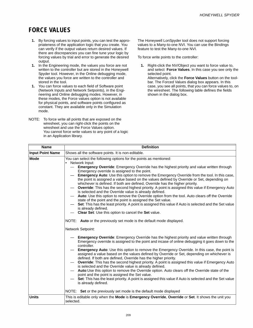
HONEYWELL SPYDER
209
FORCE VALUES1. By forcing values to input points, you can test the appro-
priateness of the application logic that you create. You can verify if the output values return desired values. If there are discrepancies you can fine tune your logic by forcing values by trial and error to generate the desired output.
1. In the Engineering mode, the values you force are not written to the controller but are stored in the Honeywell Spyder tool. However, in the Online debugging mode, the values you force are written to the controller and stored in the tool.
1. You can force values to each field of Software point (Network Inputs and Network Setpoints), in the Engi-neering and Online debugging modes. However, in these modes, the Force values option is not available for physical points, and software points configured as constant. They are available only in the Simulation mode.
NOTE: To force write all points that are exposed on the wiresheet, you can right-click the points on the wiresheet and use the Force Values option. You cannot force write values to any point of a logic in an Application library.
The Honeywell LonSpyder tool does not support forcing values to a Many-to-one NVI. You can use the Bindings feature to test the Many-to-one NVI.
To force write points to the controller:
1. Right-click the NV/Object you want to force value to, and select Force Values. In this case you see only the selected point. Alternatively, click the Force Values button on the tool-bar. The Forced Values dialog box appears. In this case, you see all points, that you can force values to, on the wiresheet. The following table defines the fields shown in the dialog box.
Name DefinitionInput Point Name Shows all the software points. It is non-editable.Mode You can select the following options for the points as mentioned:
• Neiwork Input:— Emergency Override: Emergency Override has the highest priority and value written through
Emergency override is assigned to the point.— Emergency Auto: Use this option to remove the Emergency Override from the tool. In this case,
the point is assigned a value based on the values defined by Override or Set, depending on whichever is defined. If both are defined, Override has the higher priority.
— Override: This has the second highest priority. A point is assigned this value if Emergency Auto is selected and the Override value is already defined.
— Auto: Use this option to remove the Override option from the tool. Auto clears off the Override state of the point and the point is assigned the Set value.
— Set: This has the least priority. A point is assigned this value if Auto is selected and the Set value is already defined.
— Clear Set: Use this option to cancel the Set value.
NOTE: Auto or the previously set mode is the default mode displayed.
Network Setpoint:
— Emergency Override: Emergency Override has the highest priority and value written through Emergency override is assigned to the point and incase of online debugging it goes down to the controller.
— Emergency Auto: Use this option to remove the Emergency Override. In this case, the point is assigned a value based on the values defined by Override or Set, depending on whichever is defined. If both are defined, Override has the higher priority.
— Override: This has the second highest priority. A point is assigned this value if Emergency Auto is selected and the Override value is already defined.
— Auto:Use this option to remove the Override option. Auto clears off the Override state of the point and the point is assigned the Set value.
— Set: This has the least priority. A point is assigned this value if Auto is selected and the Set value is already defined.
NOTE: Set or the previously set mode is the default mode displayedUnits This is editable only when the Mode is Emergency Override, Override or Set. It shows the unit you
selected.

HONEYWELL SPYDER
210
2. Click OK to close the dialog box. The value, in the Online Debugging mode, is directly written to the con-troller.
NOTE: Many to one NVs in LonSpyder and physical IOs will be cleared on moving to the online debugging mode, always.
ActionsUse the Actions options to quickly force values to Network Input points. You can use these options to set values based on the priority: Emergency Override > Override > Set.
Right-click the point on the wiresheet and select Actions to get to this option.
NOTE: The Actions option is not available for physical points, software points configured as constant in Online Debugging and Engineering modes, and in LonSpyder, Many-to-one NV in Online Debugging mode. They are available only in the Simulation mode.
An explanation of the actions allowed in the Online Debugging mode follows:
• Emergency Override: Emergency Override has the highest priority and value written through Emergency override is assigned to the point and incase of online debugging it goes down to the controller.
• Emergency Auto: Use this option to remove the Emergency Override from the tool. In this case, the point is assigned a value based on the values defined by Override or Set, depending on whichever is defined. If both are defined, Override has the higher priority.
• Override: This has the second highest priority. This has the second highest priority. A point is assigned this value if Emergency Auto is selected and the Override value is already defined.
• Auto: Use this option to remove the Override option from the tool. Auto clears off the Override state of the point and the point is assigned the Set value.
• Set: This has the least priority. A point is assigned this value if Auto is selected and the Set value is already defined.
NOTE: The value written to an Network Setpoint using the Set option changes the configuration of the point. That is, the value configured for the Network Set-point can also be changed using the Set option in both Online Debugging and Simulation.
Value This is editable only when the Mode is Emergency Override, Override or Set. It shows the value that you want to write to the controller.
NOTE: You can force write invalid values to a point by keying in alphabets. Such an invalid value is displayed as Nan. Any value outside the specified range is also considered invalid. For exam-ple, if the the lower range is 0 and the upper range is 20, values such as 21 or -1 are consid-ered invalid.
Upper Range This is non-editable. It shows the upper limit of the Network Variable. Lower Range This is non-editable. It shows the lower limit of the Network Variable. Select point path Indicates the location of the component. It is a relative and not an absolute path Select point ord Indicates the absolute path. It can be used to resolve the component.Clear All Invoke this option to put all the points to the default state.
For an NVI, this sets mode to Auto (i.e value = Null or to the current value in the controller) For an NCI, this sets the mode to Set with its value.
OK Saves the entered information and closes the dialog box.Cancel Closes the dialog box. Any information entered is lost.

HONEYWELL SPYDER
211
SELECT POINTS TO DEBUGNOTE: A many to one Network Input cannot be selected for
debugging.
To select points that you need to debug:
1. Click the button. The Select Points dialog box appears. The following table defines the fields shown in the dialog box.
2. Select the Function Block or Network Variable from the Select Function Block section. The output points are shown in the Select Output Points section.
3. Select the output points that you want to view. The selected points appear in the Watch Window / Point Name section.
4. Select the check box of the point you want to view in the watch window.
NOTE: Use the Select All option to select all points selected for debugging to be displayed in the watch win-dow.You can use the left arrow button to remove the selected points to the Select Output Points list. This removes the points from being seelcted for debug-ging or from being shown in the watch window. If you select All in the Select Function Blocks list and double-click it, all points are shown in the third col-umn with the watch window option checked.
5. Click OK. The points appear in the watch window.
View Values in Watch WindowYou can select points for debugging in the Engineering and Online Debugging modes. However, the selected points are displayed, in a watch window at the bottom of the wiresheet, only in the Online Debugging or Simulation modes. Use this to analyze your application logic and to find the field values being returned based on the logic you have defined.
To hide/display the watch window:
• Select Wire Sheet > Watch Window in the Menu bar or right click on the wiresheet and select Watch Window.
Changes in Select Points Screen On Changing Modes
1. If you select a point for debugging & check the watch window option in Engineering/Online Debugging mode, the same is retained in Simulation mode.
2. If you select a point for debugging & uncheck the watch window option in Engineering/Online Debugging mode, the same is not retained in Simulation mode.
3. If you select a point in the Simulation mode, the same point is retained in the Engineering/Online Debugging mode with watch window enabled.
4. If a point selected for debugging & not for watch window in the Engineering/Debugging mode is selected in the Simulation mode, the point will be retained in the Engi-neering/Debugging mode with watch window enabled.
5. If you add and remove a point in the Simulation mode, the same point is displayed as selected for debugging but not for watching in the Engineering/Online Debug-ging mode.
6. Select a point in Simulation mode. Move to the Engi-neering/Debugging mode and select the point for for both debugging & watching. Now, remove the option for watching. Move to the Simulation mode. The point will not be shown in the simulation mode.
Name Definition
Select Function Block
Shows all the Function Blocks, SBus wall module, Conventional wall module, Physical I\Os, Network Variables, Bacnet Objects, and Network Inputs that are not constants that have output points and are connected to other functional blocks or network variables. It also displays all OUT parameters of both SBus and conventional wall modules.
Select Output Points
Shows all the output points of selected Function Blocks, SBus wall module, Conventional wall module, Physical I\O, Network Variables, Bacnet Objects, and Network Inputs that are not constants and are connected to other functional blocks or network variables.
Watch Window/
Shows the selected output points that appear in the watch window. You must select the option to view points in watch window check box to be able to see the values in the watch window.
Point Name Shows the values of the output points in the watch window.
Select point path
Indicates the location of the component. It is a relative and not an absolute path
Select point ord
Indicates the absolute path. It can be used to resolve the component.
OK Saves the selected points to be debugged and closes the dialog box.t
Cancel Closes the dialog box. Any operation done so far is cancelled.

HONEYWELL SPYDER
212
SIMULATIONHoneywell Spyder provides the Simulation feature that enables you to simulate the working of your ControlProgram. Use the Simulation Mode to test the working of the ControlProgram. You can give values to Software points (Network Inputs, Network Setpoint), and Physical points.
You can also force write points to the controller and understand the behavior of the application with the values you enter and the effect it has on other points.
NOTE: You can simulate application logic with SBus wall module irrespective of the model selected. For example, if you have selected the LonSpyder I mod-els: PVL6436A, PVL6438N, or PUL6438 (these models do not support SBus wall module), and you have used SBus wall module in the application logic, you can still go ahead and simulate the application logic. However, you need to change the model type to one that supports SBus wall module before down-loading to the controller. The following Spyder mod-els support SBus wall module.
— Spyder II models: PVL6436AS, PVL6438NS, or PUL6438S
— Spyder Micro models: PVL4024NS, PVL4022AS, PUL4024S, PUL1012S, or PVL0000AS
— Spyder Bacnet models: PVB6436AS, PVB6438NS, or PUB6438S
You can also simulate the SBus wall module logic alone using the Preview feature available in the SBus wall module wizard screen.
Working in Simulation ModeYou can access the Simulation Mode from either the Engineering or Online Debugging Mode with the click of a button. To move to Simulation Mode from any mode:
Click on the Tool bar or
Right click anywhere on the wiresheet and select Simulate
The Simulate button on the tool bar becomes unselectable when you move to the Simulation mode and you have the following options available:
• Force Values: To Force write your own values to
Software input points (Network Inputs, Network Setpoints).
• Select Point: To select the points you want to
debug.
• Simulation Setup: To choose a Simulation
Setting. If you click this button in the Online Debugging
or Engineering Mode, the Simulation Settings dialog
box appears and you can choose a simulation setting.
However, the changes are only saved and are effected
only when you move to the Simulation mode. If you click
this button in the Simulation Mode, the current simulation
type is overridden by the new selection and the options you
have chosen are lost.
• Stop: To stop debugging and access the
engineering mode.
• Pause: To temporarily halt the simulation.
• Resume: This button becomes selectable only
when you have paused the simulation. If you click the
Resume button, it becomes disabled and will be available
only after pressing the Pause button.
Modify Application During SimulationYou can modify the application logic even when simulation is going on. The following table summarizes the actions and their effects on points in the Simulation mode.
Action ResultAdd/remove a block Not allowedAdd/remove a link Not allowedRename/Reorder a component ( function block, physical/software points, composite slots, macros, applications, controlprograms, device)
Not allowed
Point Conversion Not allowedAll configuration changes for function blocks except Property description change and Output property type change
Not allowed
Change Constant value through Config properties and NOT through Force values/Actions screen
Not allowed
Change NCI value through Config Properties dialog and not through Force values/Actions screen
Not allowed
Change Schedule configuration RestartChange Property description of function block AllowedChange Simulation settings Allowed and
Simulation restarts
Change Model Not allowedReassign/Unassign IO terminals in Terminal Assignment View
Not allowed
Change Daylight settings in Controller Summary View
Restart
Import XML Not allowedChange IO configuration Allowed

HONEYWELL SPYDER
213
Change Modes
NOTE: On changing the mode from Simulation to Engineer-ing/Online Debugging, the message, "Do you want to remove the overridden input point values?" message appears.
NOTE: If you select Yes:
— For Network Inputs,"Override" values are removed in the tool and the values in the controller temporarily remain until updated.
— For Software Constants (NCI) in LonSpyder, and Net-work Setpoints in BacnetSpyder, Override values except the values that have been Set are removed and the Set value are retained in the controller and in the tool.
NOTE: If you select No:
— For Network Inputs,"Override" values are retained in the tool; and the values in the controller temporarily remain until updated.
— For Software Constants (NCI) in LonSpyder, and Net-work Setpoints in BacnetSpyder, the Override value are taken as Set value and all the overridden values are removed; and values in the controller temporarily remain until updated.
— Selecting Yes may take several minutes depending on the number of wiresheet objects.
NOTE: Whenever you restart a Station, by default, the actions described on selecting No, is performed. Always, Many to one NVs in LonSpyder, and physi-cal IOs are cleared on moving to the online debug-ging mode.

HONEYWELL SPYDER
214
Example ScenarioThe entire simulation operation is explained with the aid of an example.• Create an application logic.Click the Simulate button.

HONEYWELL SPYDER
215

HONEYWELL SPYDER
216

HONEYWELL SPYDER
217
• Select the points you want to display in the Watch Window by clicking the button. Select the points you want and click OK.

HONEYWELL SPYDER
218
• The points you have selected are displayed with their values in the Watch Window.

HONEYWELL SPYDER
219
7. Click the button to select a Simulation Type. The Simulation Setup button appears. Continuous Simulation is the default selection. Enter the details and click OK.

HONEYWELL SPYDER
220
• or select the Step Simulation option. Enter the details and click OK.

HONEYWELL SPYDER
221
• or select the Time Simulation option. Enter the details and click OK.

HONEYWELL SPYDER
222
• A confirmation message is displayed. Click Yes.
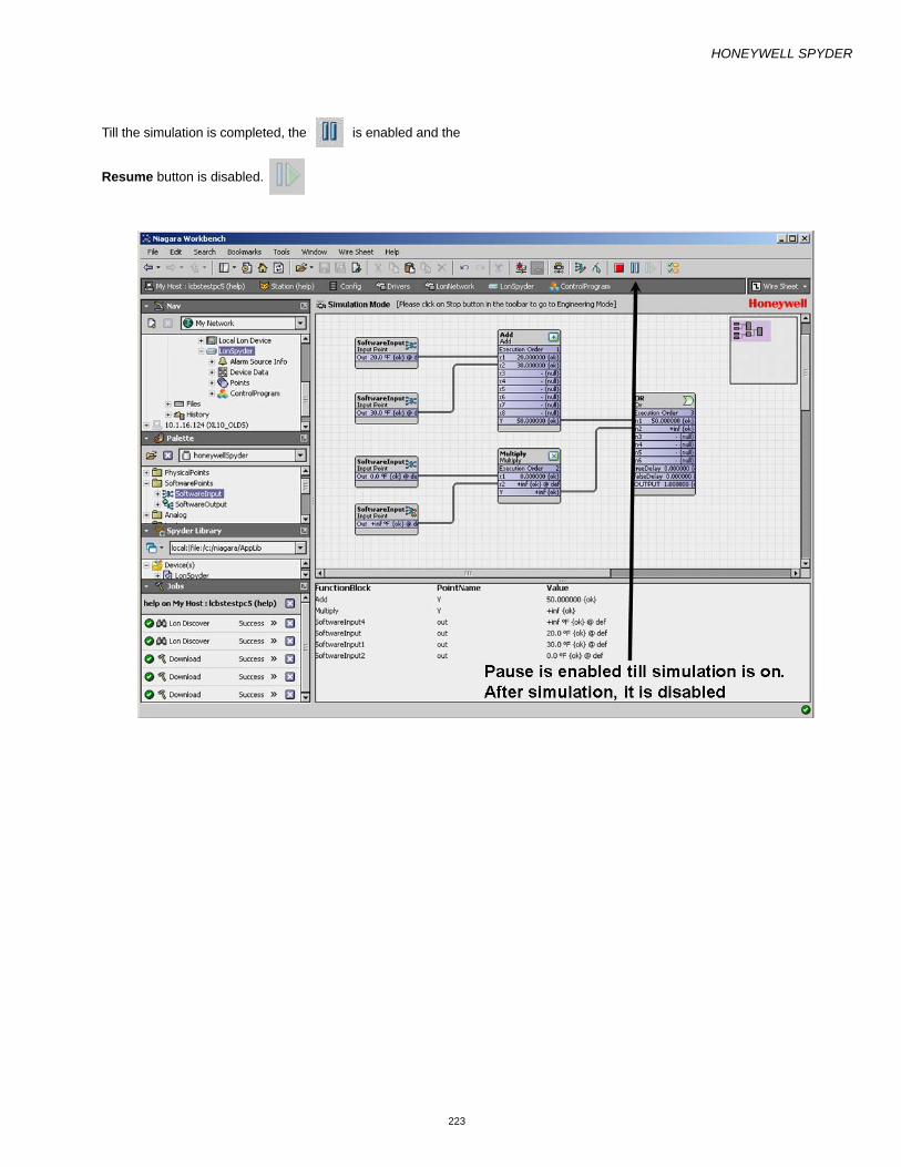
HONEYWELL SPYDER
223
Till the simulation is completed, the is enabled and the Resume button is disabled.

HONEYWELL SPYDER
224
After the simulation is complete the Pause button is disabled and the Resume button is enabled.

HONEYWELL SPYDER
225
• Click the Force Inputs button to force write Physical point values.
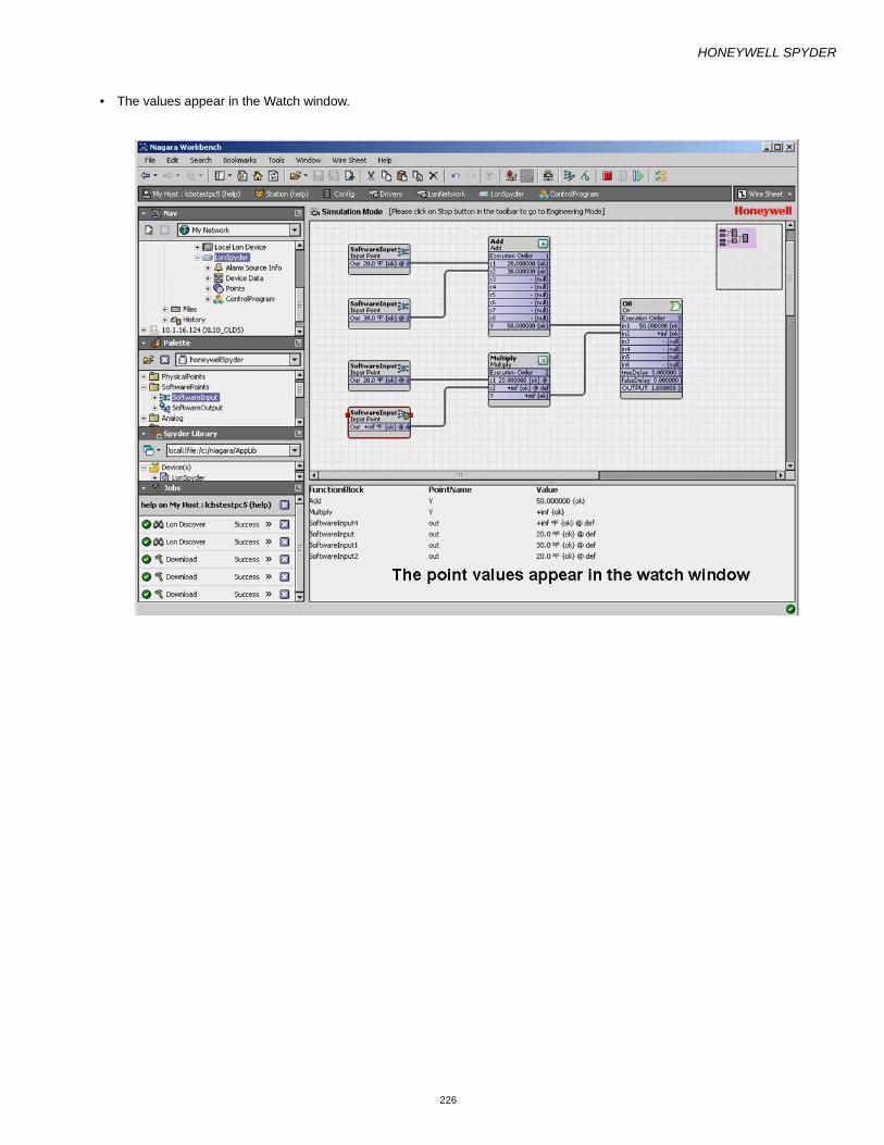
HONEYWELL SPYDER
226
• The values appear in the Watch window.

HONEYWELL SPYDER
227
• Click Stop to return to the Engineering Mode.

HONEYWELL SPYDER
228

HONEYWELL SPYDER
229
SIMULATION SETTINGSThe Honeywell Spyder has three Simulation Types that you can make use of for testing the applications you create:
• Time Simulation • Continuous Simulation • Step Simulation You can also choose to simulate at two speeds:
• Simulate as fast as possible: Select this option to choose to simulate at the fastest possible time. In this case, the simulation may be executed at speeds greater than the usual 1 second per loop.
• Simulate at the speed of the controller: Select this option to choose to simulate at the speed of the controller, which is at the rate of 1 second per loop.
NOTE: If you change simulation settings when you are in the Simulation mode, the current simulation is restarted to reflect the changes you make. However, if you make changes to Simulation Settings in the Engi-neering or Online Debugging modes, the settings are saved and take effect the next time you enter simula-tion mode.
Time SimulationUse this simulation type to simulate your application for a specified time period. The output values are calculated continuously until the specified time period is reached. To select Time Simulation type:
1. Click the button. The Simulation Setup dialog
box appears.
2. Select Time Simulation.3. Enter the Time Period in Hours, Minutes, and Seconds.
This specifies the time period over which the Honeywell Spyder Tool simulates the application logic.
4. Select the Set Start Time As option to modify the date and time. You can modify the Date, Month, Year, Hour, Minute, AM/PM by clicking it and use the up and down arrows on your keyboard. This option enables you to define (not set) the starting time of the simulation. Example: If you want to simulate an application logic in another timezone at 00:00 hours, you can select the timezone and hours and minutes. The start time of the simulation is taken as 00:00 hours although the simula-tion itself begins once you click the OK button.
5. Click OK save the changes you have made. The simu-lation of your application begins and the values of all Physical points/NV points and function blocks are dis-played on the wiresheet. Additionally, if you have selected points to be displayed in the Simulation Log Window, the values of such points are displayed in the Watch Window at the bottom of the wiresheet.
NOTE: You can use the Pause and Resume
buttons if you want to temporarily halt/resume the
simulation.
6. Click the button to enter the Engineering Mode.
Continuous SimulationUse this simulation type to simulate your application continuously. The output values are calculated continuously until you end the simulation. To select the Continuous Simulation type: :
1. Click . The Simulation Setup dialog box
appears.
2. Select Continuous Simulation.3. The Time Period is disabled and you cannot modify it.4. Select the Set Start Time As option to modify the date
and time. You can modify the Date, Month, Year, Hour, Minute, AM/PM by clicking it and use the up and down arrows on your keyboard. This option enables you to define (not set) the starting time of the simulation. Example: If you want to simulate an application logic in another timezone at 00:00 hours, you can select the timezone and hours and minutes. The start time of the simulation is taken as 00:00 hours although the simula-tion itself begins once you click the OK button.
5. Click OK save the changes you have made. The simu-lation of your application begins and the values of all Physical Points/NV points and function blocks are dis-played on the wiresheet. Additionally, if you have selected points to be displayed in the Simulation Log Window, the values of such points are displayed in the Watch Window at the bottom of the wiresheet.
NOTE: You can use the Pause and Resume
buttons if you want to temporarily halt/resume the
simulation.
6. Click the button to enter the Engineering Mode.
You can click the button to enter the Online
Debugging Mode.
Step SimulationUse this simulation type to simulate your application desired number of steps at a time. In this simulation type, the application logic you have defined is simulated based on a specified number of steps. In each step, the values of the application logic is calculated once. To select the Step Simulation type:
1. Click . The Simulation Setup dialog box
appears.
2. Select Step Simulation.3. Type the Number Of Steps.4. Select the Set Start Time As option to modify the date
and time. You can modify the Date, Month, Year, Hour, Minute, AM/PM by clicking it and use the up and down arrows on your keyboard. This option enables you to define (not set) the starting time of the simulation.

HONEYWELL SPYDER
230
— Example: If you want to simulate an application logic in another timezone at 00:00 hours, you can select the timezone and hours and minutes. The start time of the simulation is taken as 00:00 hours although the simu-lation itself begins once you click the OK button.
5. Click OK save the changes you have made. The simu-lation of your application begins and the values of all Physical Points/NV points and function blocks are dis-played on the wiresheet. Additionally, if you have selected points to be displayed in the Simulation Log Window, the values of such points are displayed in the Watch Window at the bottom of the wiresheet.
NOTE: You can use the Pause and Resume
buttons if you want to temporarily halt/resume the
simulation.
6. Click the button to enter the Engineering Mode.
You can click the button to enter the Online
Debugging Mode.
Force ValuesBy forcing values to IOs, NVs or Objects, and Function blocks you can test the appropriateness of the application logic that you create. You can verify if the output values return desired values. If there are discrepancies you can fine tune your logic by forcing values by trial and error to generate the desired
output. You can use the Force Values option to force values on physical points, software points such as Netwok Inputs, Network Setpoints and Constants, and Function blocks.
In the Simulation mode alone, you can override Functional block outputs. Use the Force Values dialog box to display the list of outputs of all functional blocks. You can also use the right-click menu to invoke the output of the selected function block alone. You can reset the overridden values of functional blocks using the Auto mode.
NOTE: While forcing values to SBus wall module, value from wall module and dynamic values which are not connected to any input slot can be over ridden.
When any one functional block output is overridden, the other outputs of that functional block also go into overridden state and the the mode of all the outputs of that functional block is changed to Override state with a default value of Nan (invalid value) for non-Enums and the first item for Enums.
Use the button to force the values of each field in an
NV, Physical point, Constant, or function block. Alternatively,
right-click on the desired IO/NV/Function block and select
Force Value.
To force write points to the controller:
1. Right-click the IO/NV you want to force value to, and select Force Values. In this case you will see only the selected point.Alternatively, click the Force Values but-

HONEYWELL SPYDER
231
ton on the toolbar. The Forced Input Screen dialog box appears. In this case, you will see all points, that you can force values to, on the wiresheet. The following table defines the fields shown in the dialog box.
2. Click OK to close the dialog box.
Name DefinitionInput Point Name Shows all the inputs and NVIs. It is non-editable.Mode You can select the following options for the points as mentioned:
• Emergency Override: Emergency Override has the highest priority and value written through Emergency override is assigned to the point.
• Emergency Auto: Use this option to remove the Emergency Override. In this case, the point is assigned a value based on the values defined by Override, Sine/Cosine/Range or Set, depending on whichever is defined. If all three are defined, Override has the higher priority
• Override: This has the second highest priority. A point is assigned this value if Emergency Auto is selected and the Override value is already defined
• Auto: Use this option to remove the Override option. Auto clears off the Override state of the point and the point is assigned the Sine/Cosine/Range value, if it is set.
• Set: This has the least priority. A point is assigned this value if Clear Sine/Cosine/Range option is selected and the Set value is already defined.
NOTE: The value written to a Network Setpoint using the Set option changes the config-uration of the point. That is, the value configured for the NCI point can also be changed using the Set option in both Online Debugging and Simulation.
• Clear Set: Use this option to remove the Set value. Not available for NCI. • Sine/Cosine/Range: This has the third highest priority. A point is assigned this value if Auto
is selected and the Sine/Cosine/Range value is already defined. The value that you specify is written to In9 slot of the point so that it goes to the point out slot.
• Clear Sine/Cos/Range: Use this option to clear the Sine/Cosine/Range value. This option removes the Sine/Cosine/Range value and assigns the Set value, if it is already defined.
Clear Set option is available for Netwotk Inputs, Constants, and Physical inputs.
The value set to the Network Setpoint through either Override, Emergency Override or Sine/Cosine/Range does not change the actual value configured for the point.
Units This is editable only when the Mode is Emergency Override, Override, Set, Sine, Cosine, and Range. It shows the unit you selected.This is not applicable o function blocks.
Value This is editable only when the Mode is Emergency Override, Override, or Set. It shows the value that you want to write to the controller.
NOTE: You can force write invalid values to a point by keying in alphabets. Such an invalid value is displayed as Nan. Any value outside the specified range is also considered invalid. For example, if the the lower range is 0 and the upper range is 20, values such as 21 or -1 are considered invalid..
Upper Range It shows the upper limit of the Network Variable. This is non-editable except for Sine, Cosine, and Range.
Lower Range It shows the lower limit of the Network Variable. This is non-editable except for Sine, Cosine, and Range.
Select point path Indicates the location of the component. It is a relative and not an absolute path Select point ord Indicates the absolute path. It can be used to resolve the component.Clear All Invoke this option to put all the points/Function blocks to the default state. NCIs/Network
Setpoints go back to their configured value, NVIs/Network Inputs go to null, function block outputs go back to null.
OK Saves the entered information and closes the dialog box.Cancel Closes the dialog box. Any information entered is lost.

HONEYWELL SPYDER
232
ActionsUse the Actions options to quickly force values. You can use these options to set values based on the priority: Emergency Override > Override Sine/Cosine/Range > Set.
An explanation of the actions allowed in the Online Debugging mode follows:
• Emergency Override: Emergency Override has the highest priority and value written through Emergency override is assigned to the point and incase of online debugging it goes down to the controller.
• Emergency Auto: Use this option to remove the Emergency Override. In this case, the point is assigned a value based on the values defined by Override, Sine/Cosine/Range or Set, depending on whichever is defined. If all three are defined, Override has the higher priority.
• Override: This has the second highest priority. The value written through Override is assigned if it is already defined.
• Auto: Use this option to remove the Override option. Auto clears off the Override state of the point and the point is assigned the Sine/Cosine/Range value, if it is set.
• Set: This has the least priority. A point is assigned this value if Clear Sine/Cosine/Range option is selected and the Set value is already defined.
NOTE: The value written to a Network Setpoint using the Set option changes the configuration of the point. That is, the value configured for the Network Setpoint can also be changed using the Set option in both Online Debugging and Simulation.
Right-click the point on the wiresheet and select Actions to get to this option.
Select Points to Display in Simulation Log Window
Pre-requisites— To be able to simulate function blocks, they must be
linked to other function blocks or output points or con-figured as Out_Save, Out_Byte, Out_float, or con-stant. An exception, however, is the Alarm function block. If you have an Alarm function block with only its input linked, you can still perform simulation.
— To be able to simulate input points (Network Inputs, Network Setpoints, analog inputs, and binary inputs), they must be linked to function blocks or other output points.
— To select the points being simulated that need to be visible in the Watch Window:
NOTE: All points in the logic will be simulated. However, only those points for which you have enabled the View in Watch Window option are displayed in the watch window.
1. Click the Select Points button on the tool bar. The Select Points to be displayed in the Simulation Log Window dialog box appears. The following table defines the fields shown in the dialog box.
2. Select the Function Block or Network Variable from the Select Function Block section. The output points are shown in the Select Output Points section.
3. Select the output points that you want to view. The selected points appear in the Point Name section.
4. Click OK. The points appear in the watch window with the values.
View Values in Watch WindowAfter you have selected points to be displayed in the Simulation Log Window, the points appear in a Watch Window at the bottom of the wiresheet. Use this to analyze your application logic and to find the values being returned based on the logic you have defined.
NOTE: All points in the logic will be simulated. However, only those points for which you have enabled the View in Watch Window option are displayed in the watch window
Changes in Select Points Screen On Changing ModesAfter you have selected the points to be debugged, if you switch to another mode and select/unselect the points to be debugged and then get back to the Online Debugging Mode, the selected points are not selected to be displayed in the watch window. You have to select them again.
1. If you select a point for debugging & enable the watch window option in Engineering/Debugging mode, it is retained in Simulation mode.
2. If you select a point for debugging and uncheck the watch window option in Engineering/Debugging mode, the same is not retained in Simulation mode.
Name DefinitionSelect Function Block
Shows all the Function Blocks, Physical I\O's and Network Inputs, Network Setpoints, Physical inputs such as analog and digital inputs that have output points and are connected to other functional blocks or Network Output points.
Select Output Points
Shows all the output slots of the selected components in the Select Funtion Block list.
Select point path
Indicates the location of the component. It is a relative and not an absolute path
Select point ord
Indicates the absolute path. It can be used to resolve the component.
Point Name Shows the points selected to be displayed in the watch window.
OK Saves the selected points to be debugged and closes the dialog box.
Cancel Closes the dialog box. Any operation done so far is cancelled.

HONEYWELL SPYDER
233
3. If you select a point in Simulation mode, it is retained in Engineering/Debugging mode with the watch window enabled.
4. Select a point for debugging and with the watch window option unchecked in Engineering/Debugging mode. If you select the same point in Simulation mode, then on returning to the Engineering/Online Debugging mode, you will find this point is with the watch window option enabled.
5. If you add and remove a point in Simulation mode, the same point is selected for debugging but not for watch-ing in the Engineering/Online Debugging mode.
6. Select a point in Simulation mode. Go to the Engineer-ing/Debugging mode and see that it is selected for both Debug & watching. Now, uncheck the watch window option. You will find that it is not shown in Simulation mode.
NOTE:
• The value written to a point and the mode last set (in Engineering/Online debugging/Simulation) will be available the next time you visit any other mode (Engineering/Online debugging/Simulation) with the following exceptions:
— If Sine/Cosine/Range was selected for a point in Simu-lation mode and you enter the Engineering/Online Debugging mode, and invoke the Force Input screen, the mode for that point is shown as Set/Auto. If you click OK and go to the Simulation mode, the Force Input screen indicates the mode as Set/Auto.
— If Sine/Cosine/Range is selected for a point in Simula-tion mode and the you enter the Engineering/Online Debugging mode, and invoke the Force Input screen, the mode for that point is shown as Set/Auto. If you click Cancel and visit the Simulation mode, the Force Input screen will indicate the mode as Sine/Cosine/Range (depending on what was last selected).
— If Sine/Cosine/Range is selected for a point in Simula-tion mode and you enter the Engineering /Online Debugging mode, and do not invoke Force Input screen or any option in the right click menu on that point and go to the Simulation mode again, the Force Input screen indicates the mode as Sine/Cosine/Range (depending on what was last selected).
— The values set for constant blocks are not saved across mode revisits. When you exit Simulation mode, the actual value configured for the constant block is put back on the out slot.

HONEYWELL SPYDER
234
GENERATE XIF FILELONMARK external interface files(.xif) are files that define the external interface for one or more LONWORKS devices. The external interface is the interface to a device that is exposed over a LONWORKS network. The external interface does not expose the internal algorithms of a device, instead, it only exposes the inputs to the algorithms and the outputs from the algorithms.
The external interface file includes the program ID information of the device, application type information, self-documentation information, the configuration information of network variables.
There are two benefits to using external interface files. First, an external interface file may include information that is not included in a device such as network variable names. Second, an external interface file can be used during network engineering when the device is not accessible from the network engineering tool.
To generate an XIF file:
• Right-click the device in the Nav palette and select Actions > Generate XIF. The XIF file is generated and stored at the following location: Drive:\\Niagara\Niagara-x-x-xx\XIF
HONEYWELL SPYDER
235
ORDER OF EXECUTIONThe order of execution defines the sequence in which function blocks are executed by the controller. When you drag function blocks on to a wire sheet to build an application logic, by default, the tool sets the execution order of the functional blocks in the order you drop them on to the wire sheet. However, you can alter the order in which the controller executes the function blocks by re-ordering the blocks. In the Simulation Mode, the order of execution that you set is followed.
NOTE: You can reorder the execution of function blocks only. Although NVs or Bacnet objects and Physical points are shown in the Reorder screen, you cannot reorder their order of execution.
NOTE: When you remove a block, the order of execution gets affected.
NOTE: You cannot change the order of execution for Built In function blocks.
NOTE: Execution order for blocks within a macro or Applica-tion is maintained based on the order in which you drag the blocks within them.
To change the order of execution:
1. From the Spyder Palette, drag function blocks, macros or Programs on the wiresheet. The order in which you drag the function blocks determines the execution order. The execution order is displayed on the container of each function block on the wiresheet.
2. Right-click the specific container or ControlProgram in the Nav sidebar. Click Reorder. The Reorder dialog box appears.
3. Select the required application and click Move Up or Move Down to change the order of execution.
4. Click OK to close the dialog box.

HONEYWELL SPYDER
236
CUSTOM PALETTE FILECreate and use a custom palette file to store any Spyder object application, macro, device, FBs, IOs from a station. You can use this file to share it across Stations and among multiple users. This custom palette file acts only as a repository but you can not configure an object that exists in the palette.
You can later copy and paste or drag and drop these objects from the custom palette to the station.
Create Custom Palette FileTo create a custom palette file:
1. On the Nav sidebar, navigate to the drive where you want to create the custom palette file. Right click the drive and select New Folder. A new folder is created.
2. Enter a name for the new folder and click OK. 3. Right click the new folder and select New > Palette-
file.palette
4. Enter a name for the palette file and click OK. A new palette file is created. Expand the newly created folder to view the palette file that you just now created.
5. Double click the palette folder to open its wiresheet. 6. On the Palette sidebar, click the Open Palette button.
The Open Palette dialog box appears. 7. Select Baja module and click OK. You will see the
UnrestrictedFolder in the Baja Palette (Palette sidebar with Baja module selected).
8. Drag the unrestricted folder in to the folder with the pal-ette file that you have created. A .bog file appears in the folder which contains the unrestricted folder.
9. Double-click the UnrestrictedFolder.bog file that was added to the new folder, to open its wiresheet.
10. Right-click on the folder to rename it. This is the Unre-stricted folder where you can store all Spyder objects.
NOTE: You can double click the folder on the wiresheet and drag the UnrestrictedFolder object from the Palette palette on to the wiresheet. This has the effect of nesting folders within the palette file. This enables you to categorize objects that are stored in the pal-ette file. For example, you can drag an Unrestrict-edFolder from the Baja palette (Palette palette with Baja module selected) on to the wiresheet of the pal-ette file and name it Applications. You can then dou-ble-click the Applications folder on the wiresheet and drag another UnrestrictedFolder object from the Baja palette and name it VAV Applications. This cre-ates the VAV Applications folder under the Applica-tions folder in a tree structure in the custom palette file you are creating.
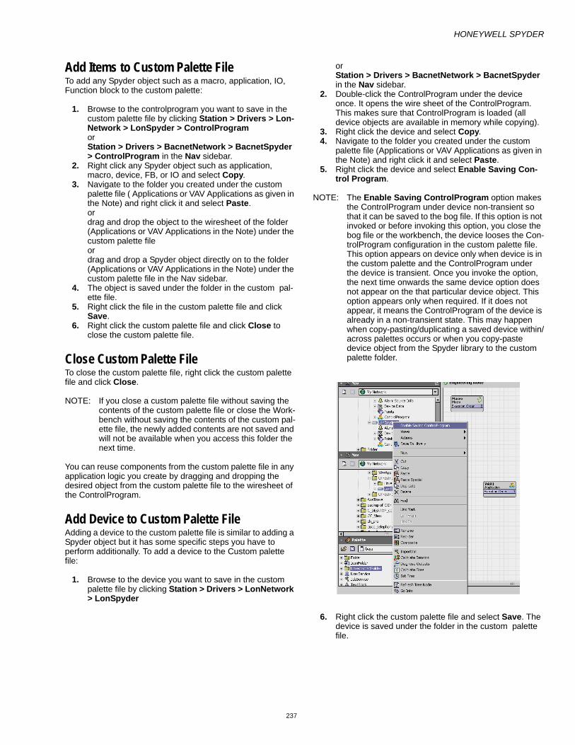
HONEYWELL SPYDER
237
Add Items to Custom Palette FileTo add any Spyder object such as a macro, application, IO, Function block to the custom palette:
1. Browse to the controlprogram you want to save in the custom palette file by clicking Station > Drivers > Lon-Network > LonSpyder > ControlProgram or Station > Drivers > BacnetNetwork > BacnetSpyder > ControlProgram in the Nav sidebar.
2. Right click any Spyder object such as application, macro, device, FB, or IO and select Copy.
3. Navigate to the folder you created under the custom palette file ( Applications or VAV Applications as given in the Note) and right click it and select Paste. or drag and drop the object to the wiresheet of the folder (Applications or VAV Applications in the Note) under the custom palette file or drag and drop a Spyder object directly on to the folder (Applications or VAV Applications in the Note) under the custom palette file in the Nav sidebar.
4. The object is saved under the folder in the custom pal-ette file.
5. Right click the file in the custom palette file and click Save.
6. Right click the custom palette file and click Close to close the custom palette file.
Close Custom Palette FileTo close the custom palette file, right click the custom palette file and click Close.
NOTE: If you close a custom palette file without saving the contents of the custom palette file or close the Work-bench without saving the contents of the custom pal-ette file, the newly added contents are not saved and will not be available when you access this folder the next time.
You can reuse components from the custom palette file in any application logic you create by dragging and dropping the desired object from the custom palette file to the wiresheet of the ControlProgram.
Add Device to Custom Palette FileAdding a device to the custom palette file is similar to adding a Spyder object but it has some specific steps you have to perform additionally. To add a device to the Custom palette file:
1. Browse to the device you want to save in the custom palette file by clicking Station > Drivers > LonNetwork > LonSpyder
or Station > Drivers > BacnetNetwork > BacnetSpyder in the Nav sidebar.
2. Double-click the ControlProgram under the device once. It opens the wire sheet of the ControlProgram. This makes sure that ControlProgram is loaded (all device objects are available in memory while copying).
3. Right click the device and select Copy. 4. Navigate to the folder you created under the custom
palette file (Applications or VAV Applications as given in the Note) and right click it and select Paste.
5. Right click the device and select Enable Saving Con-trol Program.
NOTE: The Enable Saving ControlProgram option makes the ControlProgram under device non-transient so that it can be saved to the bog file. If this option is not invoked or before invoking this option, you close the bog file or the workbench, the device looses the Con-trolProgram configuration in the custom palette file. This option appears on device only when device is in the custom palette and the ControlProgram under the device is transient. Once you invoke the option, the next time onwards the same device option does not appear on the that particular device object. This option appears only when required. If it does not appear, it means the ControlProgram of the device is already in a non-transient state. This may happen when copy-pasting/duplicating a saved device within/across palettes occurs or when you copy-paste device object from the Spyder library to the custom palette folder.
6. Right click the custom palette file and select Save. The device is saved under the folder in the custom palette file.

HONEYWELL SPYDER
238
DEVICE ICONSYou can add Lon and Bacnet devices to the station to create Control Programs and Applications. The Control Program or Application logic is downloaded to the controller or saved to the library. The state of the device is represented by the device icon. The Lon and Bacnet device icons differ in their appearance depending on 5 conditions.
Lon Icons• The Lon device icon is Normal in the Palette and
Spyder Library sidebars. • The Lon device icon is Download Pending when the
device is dropped onto the Nav sidebar. • The Lon device icon is Downloaded State when the
Control Program or Application has been downloaded to the controller.
• The Lon device icon is Quick Download Pending when the Control Program or Application logic is modified and is pending for a quick download to the controller.
• The Lon device icon is Binding Pending when a new link is added to a downloaded device and is pending for binding. After binding the device, the icon goes to Downloaded State.
NOTE:
— If the download fails, the device icon is Download Pending.
— If changes are made to the Object Configuration View of the device, the icon is Download Pending.
— If a new link is added to a Lon device which is in Download Pending state, the device icon remains in the Download Pending state.
— When a link is created between two Lon devices, both the device icons are in Binding Pending state.
Bacnet Icons• The Bacnet device icon is Normal in the Palette and
Spyder Library sidebars.
• The Bacnet device icon is Download Pending when the device is dropped onto the Nav sidebar.
• The Bacnet device icon is Downloaded State when the Control Program or Application has been downloaded to the controller.
• The Bacnet device icon is Quick Download Pending when the Control Program or Application logic is
modified and is pending for a quick download to the controller.
• The Bacnet device icon is Binding Pending when a new link is added to a downloaded device and is pending for binding. After binding the device, the icon goes to Downloaded State.
NOTE:
— If the download fails, the device icon is Download Pending.
— If changes are made to the Object Configuration View of the device, the icon is Download Pending.
— If a new link is added to a Lon device which is in Download Pending state, the device icon remains in the Download Pending state.
— When a link is created between two Bacnet devices, the source device icon is in Binding Pending state when the link status is Push. The target device icon is in Binding Pending state when the link status is Poll.
Device Icons in Library• When a new device is added to the Spyder library, the
device icon is in Normal state. • When you save a Control Program or Application logic
from the station to the Spyder library, the device icon is in Normal state.
• When a device is dragged from the Spyder Library onto the Nav sidebar, the device icon is in Download Pending state.

HONEYWELL SPYDER
239
VIRTUAL OFFLINE DISCOVERYUsing the Virtual feature you can view the online and offline points of the device.
To view the online and offline points of the device:
1. Expand the Bacnet device on the Nav sidebar. 2. Right-click Virtual and choose Actions. 3. Select Online Discovery to view the online points of
the device. or Select Offline Discovery to view the fixed, mandatory, and offline points of the device.
NOTE:
— The points in online or offline discovery mode are automatically unloaded after a specific time.
— A point which is left expanded in offline discovery mode is not unloaded.
The mode of operation can be restored from offline discovery to online discovery in the following two ways.
1. Choose Virtual > Actions > Online Discovery and forcibly change the mode.
2. Click Virtual when one of the points in offline discovery mode is unloaded. The mode is restored to online dis-covery.
The online/offline points can be used in a Px view.
To create a new Px view:
1. Right-click the Bacnet device on the Nav sidebar. 2. Choose Views > New View. The New Px View dialog
box appears. 3. Type the View Name and click OK. The screen displays
the new view.
To use the offline point on the Px view:
1. Create an application logic on the wiresheet under Con-trolProgram.
2. Right-click Virtual and select Offline Discovery. 3. Expand Virtual to view the online points on the Nav
sidebar. 4. Expand the point and drag the required property from
the Nav sidebar onto the Px view. 5. Right-click the Bacnet device and select Views to view
the Px view you have created.
To view the online values from the device:
1. Download the application logic to the controller. 2. Right-click Virtual and select Online Discovery. 3. Right-click the Bacnet device and select Views. 4. Select the Px view you have created to see the online
values.

HONEYWELL SPYDER
Automation and Control SolutionsHoneywell International Inc. Honeywell Limited-Honeywell Limitée1985 Douglas Drive North 35 Dynamic DriveGolden Valley, MN 55422 Scarborough, Ontario M1V 4Z9www.honeywell.com/buildingsolutions
® U.S. Registered Trademark© 2009 Honeywell International Inc. HTS Rev. 07-09