Embed Size (px)
DESCRIPTION
Honeywell HCX Series Network IP Camera Operator Guide
Citation preview

Document 800-01794 – Rev A – 04/08
Operator Guide
HCX SeriesNetwork IP Camera
HCX13MHCX3HCX5D

2
Revisions
Issue Date Revisions
A 04/08 New document.

HCX Series Network IP Camera Operator Guide
Document 800-01794 Rev A 304/08
Warnings
Installation and servicing should be performed only by qualified and experienced technicians to conform to all local codes and to maintain your warranty.
WARNING! 12 VDC/24 VAC models require the use of CSA Certified/UL Listed Class 2 power adapters to ensure compliance with electrical safety standards.
WEEE (Waste Electrical and Electronic Equipment). Correct disposal of this product (applicable in the European Union and other European countries with separate collection systems). This product should be disposed of, at the end of its useful life, as per applicable local laws, regulations, and procedures.

4
Explanation of Graphical Symbols
Important Safeguards
• Read and keep these instructions.• Heed all warnings.• Follow all instructions. • Do not use this apparatus near water.• Clean only with dry cloth.• Do not block any ventilation openings. Install in accordance with the manufacturer’s
instructions.• Do not install near any heat sources such as radiators, heat registers, stoves, or
other apparatus (including amplifiers) that produce heat.• Use only with the cart, stand, tripod, bracket, or table specified by the manufacturer,
or sold with the apparatus.
FCC Compliance Statement
Information to the User: This equipment has been tested and found to comply with the limits for a Class A digital device. Pursuant to Part 15 of the FCC Rules, these limits are designed to provide reasonable protection against harmful interference when the equipment is operated in a commercial environment. This equipment generates, uses,

HCX Series Network IP Camera Operator Guide
Document 800-01794 Rev A 504/08
and can radiate radio frequency energy and, if not installed and used in accordance with the instruction manual, may cause harmful interference in which case the user will be required to correct the interference at his own expense.
Caution Changes or modifications not expressly approved by the party responsible for compliance could void the user’s authority to operate the equipment.
This Class A digital apparatus complies with Canadian ICES-003.
Manufacturer’s Declaration of Conformance
The manufacturer declares that the equipment supplied with this guide is compliant with the essential protection requirements of the EMC directive 2004/108/EC, conforming to the requirements of standards EN 55022 for emissions, EN 55024 for immunity, and LVD 2006/95/EC for Electrical Equipment safety.

6

HCX Series Network IP Camera Operator Guide
Document 800-01794 Rev A 704/08
ContentsIntroduction . . . . . . . . . . . . . . . . . . . . . . . . . . . . . . . . . . . . . . . . . . . . . . . . 12
About This Guide . . . . . . . . . . . . . . . . . . . . . . . . . . . . . . . . . . . . . . . . . . . . . 12
Installation . . . . . . . . . . . . . . . . . . . . . . . . . . . . . . . . . . . . . . . . . . . . . . . . 13
HCXFinder . . . . . . . . . . . . . . . . . . . . . . . . . . . . . . . . . . . . . . . . . . . . . . . . 15
Installing HCXFinder . . . . . . . . . . . . . . . . . . . . . . . . . . . . . . . . . . . . . . . . . . . 15Assigning an IP Address . . . . . . . . . . . . . . . . . . . . . . . . . . . . . . . . . . . . . . . . . 15
Configuration . . . . . . . . . . . . . . . . . . . . . . . . . . . . . . . . . . . . . . . . . . . . . . . . 17
Getting Help . . . . . . . . . . . . . . . . . . . . . . . . . . . . . . . . . . . . . . . . . . . . . . . 18Image Settings . . . . . . . . . . . . . . . . . . . . . . . . . . . . . . . . . . . . . . . . . . . . . . 19
Gain Settings . . . . . . . . . . . . . . . . . . . . . . . . . . . . . . . . . . . . . . . . . . 21Overlays. . . . . . . . . . . . . . . . . . . . . . . . . . . . . . . . . . . . . . . . . . . . . 22
Window Screen . . . . . . . . . . . . . . . . . . . . . . . . . . . . . . . . . . . . . . . . . . . . . . 23Crop Tab . . . . . . . . . . . . . . . . . . . . . . . . . . . . . . . . . . . . . . . . . . . . 23Exposure Tab . . . . . . . . . . . . . . . . . . . . . . . . . . . . . . . . . . . . . . . . . . 24Privacy Tab . . . . . . . . . . . . . . . . . . . . . . . . . . . . . . . . . . . . . . . . . . . 25Motion Detection . . . . . . . . . . . . . . . . . . . . . . . . . . . . . . . . . . . . . . . . 26
Network Setup . . . . . . . . . . . . . . . . . . . . . . . . . . . . . . . . . . . . . . . . . . . . . . 29Setting E-mail (SMTP) . . . . . . . . . . . . . . . . . . . . . . . . . . . . . . . . . . . . . 31Setting the Time . . . . . . . . . . . . . . . . . . . . . . . . . . . . . . . . . . . . . . . . 31
Security Setup . . . . . . . . . . . . . . . . . . . . . . . . . . . . . . . . . . . . . . . . . . . . . . 33Setting Passwords . . . . . . . . . . . . . . . . . . . . . . . . . . . . . . . . . . . . . . . 33Setting Access Hours . . . . . . . . . . . . . . . . . . . . . . . . . . . . . . . . . . . . . . 35Updating Camera Firmware . . . . . . . . . . . . . . . . . . . . . . . . . . . . . . . . . . 35
Trigger Settings. . . . . . . . . . . . . . . . . . . . . . . . . . . . . . . . . . . . . . . . . . . . . . 36Setting E-mail Settings . . . . . . . . . . . . . . . . . . . . . . . . . . . . . . . . . . . . . 37Configuring FTP Settings . . . . . . . . . . . . . . . . . . . . . . . . . . . . . . . . . . . . 38Checking E-mail and FTP Status . . . . . . . . . . . . . . . . . . . . . . . . . . . . . . . . 39
Configuring I/O Settings . . . . . . . . . . . . . . . . . . . . . . . . . . . . . . . . . . . . . . . . . 41Setting Button Attributes . . . . . . . . . . . . . . . . . . . . . . . . . . . . . . . . . . . . 42Setting Relay Action . . . . . . . . . . . . . . . . . . . . . . . . . . . . . . . . . . . . . . 43Configuring Analog Output . . . . . . . . . . . . . . . . . . . . . . . . . . . . . . . . . . . 43
Configuring Multiview Settings . . . . . . . . . . . . . . . . . . . . . . . . . . . . . . . . . . . . . . 44
Specifications . . . . . . . . . . . . . . . . . . . . . . . . . . . . . . . . . . . . . . . . . . . . . . . . 45

8

HCX Series Network IP Camera Operator Guide
Document 800-01794 Rev A 904/08
FiguresFigure 1-1 HCXFinder List of Detected Cameras . . . . . . . . . . . . . . . . . . . . . . . . . . . . . 13
Figure 1-2 Assign IP Address . . . . . . . . . . . . . . . . . . . . . . . . . . . . . . . . . . . . . . . 14
Figure 1-3 Live Window . . . . . . . . . . . . . . . . . . . . . . . . . . . . . . . . . . . . . . . . . . 15
Figure 1-4 Image Screen . . . . . . . . . . . . . . . . . . . . . . . . . . . . . . . . . . . . . . . . . 17
Figure 1-5 Image Settings Dialog Box . . . . . . . . . . . . . . . . . . . . . . . . . . . . . . . . . . 17
Figure 1-6 Gain Settings Dialog Box . . . . . . . . . . . . . . . . . . . . . . . . . . . . . . . . . . . 19
Figure 1-7 Overlays Dialog Box . . . . . . . . . . . . . . . . . . . . . . . . . . . . . . . . . . . . . . 21
Figure 1-8 Window Screen . . . . . . . . . . . . . . . . . . . . . . . . . . . . . . . . . . . . . . . . 22
Figure 1-9 Exposure Tab . . . . . . . . . . . . . . . . . . . . . . . . . . . . . . . . . . . . . . . . . 23
Figure 1-10 Live View with Automatic Exposure Window . . . . . . . . . . . . . . . . . . . . . . . . . 23
Figure 1-11 Privacy Tab. . . . . . . . . . . . . . . . . . . . . . . . . . . . . . . . . . . . . . . . . . . 24
Figure 1-12 Window Screen with 4 Privacy Zones . . . . . . . . . . . . . . . . . . . . . . . . . . . . . 25
Figure 1-13 Window Screen with Motion Detection . . . . . . . . . . . . . . . . . . . . . . . . . . . . 25
Figure 1-14 Network Screen . . . . . . . . . . . . . . . . . . . . . . . . . . . . . . . . . . . . . . . . 28
Figure 1-15 Email Dialog . . . . . . . . . . . . . . . . . . . . . . . . . . . . . . . . . . . . . . . . . . 30
Figure 1-16 Time Dialog . . . . . . . . . . . . . . . . . . . . . . . . . . . . . . . . . . . . . . . . . . 30
Figure 1-17 Security Screen . . . . . . . . . . . . . . . . . . . . . . . . . . . . . . . . . . . . . . . . 32
Figure 1-18 Access Hours Dialog . . . . . . . . . . . . . . . . . . . . . . . . . . . . . . . . . . . . . 34
Figure 1-19 Trigger Settings Screen . . . . . . . . . . . . . . . . . . . . . . . . . . . . . . . . . . . . 35
Figure 1-20 E-mail Dialog Box . . . . . . . . . . . . . . . . . . . . . . . . . . . . . . . . . . . . . . . 36
Figure 1-21 FTP Dialog Box . . . . . . . . . . . . . . . . . . . . . . . . . . . . . . . . . . . . . . . . 37
Figure 1-22 E-mail and FTP Status . . . . . . . . . . . . . . . . . . . . . . . . . . . . . . . . . . . . . 38
Figure 1-23 I/O Settings Screen . . . . . . . . . . . . . . . . . . . . . . . . . . . . . . . . . . . . . . 41
Figure 1-24 Button Attributes Dialog . . . . . . . . . . . . . . . . . . . . . . . . . . . . . . . . . . . . 41
Figure 1-25 Relay Action Dialog . . . . . . . . . . . . . . . . . . . . . . . . . . . . . . . . . . . . . . 42
Figure 1-26 Analog Output Dialog . . . . . . . . . . . . . . . . . . . . . . . . . . . . . . . . . . . . . 42
Figure 1-27 MultiView Settings Screen . . . . . . . . . . . . . . . . . . . . . . . . . . . . . . . . . . . 43

10
HCX Series Network IP Camera Operator Guide
Document 800-01794 Rev A 1104/08
TablesTable 1-1 Image Settings Fields. . . . . . . . . . . . . . . . . . . . . . . . . . . . . . . . . . . . . . 18
Table 1-2 Gain Settings Fields . . . . . . . . . . . . . . . . . . . . . . . . . . . . . . . . . . . . . . 20
Table 1-3 Overlay Settings Fields . . . . . . . . . . . . . . . . . . . . . . . . . . . . . . . . . . . . . 21
Table 1-4 Threshold Settings Fields. . . . . . . . . . . . . . . . . . . . . . . . . . . . . . . . . . . . 27
Table 1-5 Network Settings Fields . . . . . . . . . . . . . . . . . . . . . . . . . . . . . . . . . . . . 28
Table 1-6 Email Settings Fields . . . . . . . . . . . . . . . . . . . . . . . . . . . . . . . . . . . . . . 30
Table 1-7 Time Settings Fields . . . . . . . . . . . . . . . . . . . . . . . . . . . . . . . . . . . . . . 31
Table 1-8 Passwords Fields . . . . . . . . . . . . . . . . . . . . . . . . . . . . . . . . . . . . . . . . 33
Table 1-9 Trigger Settings Fields . . . . . . . . . . . . . . . . . . . . . . . . . . . . . . . . . . . . . 35
Table 1-10 E-mail Fields . . . . . . . . . . . . . . . . . . . . . . . . . . . . . . . . . . . . . . . . . . 37
Table 1-11 FTP Fields. . . . . . . . . . . . . . . . . . . . . . . . . . . . . . . . . . . . . . . . . . . . 37
Table 1-12 Dynamic Variables . . . . . . . . . . . . . . . . . . . . . . . . . . . . . . . . . . . . . . . 40
Table 1-13 Button Attributes Fields . . . . . . . . . . . . . . . . . . . . . . . . . . . . . . . . . . . . . 41
Table 1-14 Relay Action Fields . . . . . . . . . . . . . . . . . . . . . . . . . . . . . . . . . . . . . . . 42
Table 1-15 Multiview Fields . . . . . . . . . . . . . . . . . . . . . . . . . . . . . . . . . . . . . . . . . 43
Table 1-16 Camera Specifications . . . . . . . . . . . . . . . . . . . . . . . . . . . . . . . . . . . . . 44

12
Introduction
The HCX Series high speed network megapixel cameras deliver hi-speed, high quality images even in low-light. With the HCX Series cameras in your network, you can record crisp, clear megapixel images while, at the same time, viewing low-bandwidth video.
About This Guide
This guide explains how to plug your HCX Series network camera into the network and then use the Honeywell HCXFinder Utility to:
• Assign an IP address to your HCX Series Network IP camera• Configure each HCX Series Network IP camera in your network• Secure your Network IP camera system against unwanted access• Limit access to camera images at certain times• Update firmware to your Network IP cameras• Set your cameras to capture sequences in response to trigger events• Set when and to whom e-mails will be sent after trigger events• Designate an FTP server to which your camera transfers trigger images• Configure the relay output of your Network IP cameras• Set up your cameras to deliver a web page showing streaming images from up to
nine cameras, simultaneously
This guide is written for installers and network administrators. Advanced users—those who understand digital imaging and networking—may find the information in this guide useful for optimizing the performance of their network cameras.
Note Changes may be made to this guide from time to time. Honeywell recommends that you obtain the most current version from the product page at www.honeywellvideo.com.

HCX Series Network IP Camera Operator Guide
Document 800-01794 Rev A 1304/08
Installation
1. Plug your HCX Series camera into the network.
2. Before applying power, verify you are using the correct power supply.
The HCX Series cameras can be powered directly or via the Ethernet using an IEEE 802.3af power source.
Powered Direct:
The input voltage is 12 - 24 VDC or 24 VAC, and the polarity is not important.
Powered via the Ethernet:
Requires an IEEE 802.3af compliant Power over Ethernet (PoE) power injector or switch.
3. After power is applied, the HCX Series cameras can be focused using a field service monitor. If no analog monitor is available then focus must be performed by using a browser to view the camera images.
E T H E R N E T8 0 2 . 3 a fP o E
V I D E OO U T
E t h e r n e t H C X 5 D0 0 – 5 0 – 1 A – D 0 – 0 0 – 1 1
P O W E R2 4 V ~ 1 2 - 2 4 V
C F M E D I A
T R I G G E R- I N + - O U T +
P OW E R2 4 V ~ 1 2 - 2 4 V
E T H E R N E T8 0 2 . 3 a fPo E V I D E O
O U T
E t h e r n e t H C X 1 3 M0 0 – 5 0 – 1 A – D 0 – 0 0 – 1 1
HCX13M
HCX3 / HCX5D
PoE connection
PoE connection
Direct connection
Direct connection
14
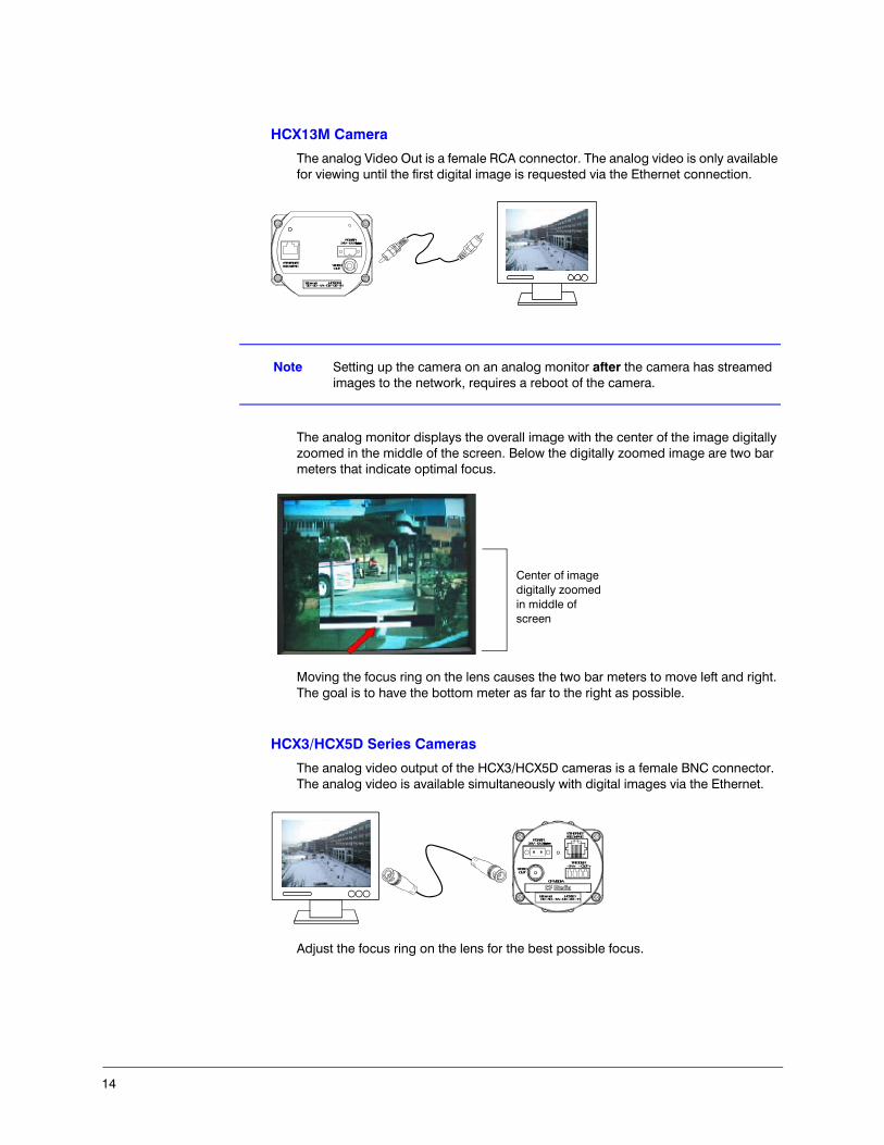
HCX13M Camera
The analog Video Out is a female RCA connector. The analog video is only available for viewing until the first digital image is requested via the Ethernet connection.
Note Setting up the camera on an analog monitor after the camera has streamed images to the network, requires a reboot of the camera.
The analog monitor displays the overall image with the center of the image digitally zoomed in the middle of the screen. Below the digitally zoomed image are two bar meters that indicate optimal focus.
Moving the focus ring on the lens causes the two bar meters to move left and right. The goal is to have the bottom meter as far to the right as possible.
HCX3/HCX5D Series Cameras
The analog video output of the HCX3/HCX5D cameras is a female BNC connector. The analog video is available simultaneously with digital images via the Ethernet.
Adjust the focus ring on the lens for the best possible focus.
POWER24V~ 12-24V
ETHERNET802.3afPoE VIDEO
OUT
Ethernet HCX13M00 – 50 – 1A – D0 – 00 – 11
Center of image digitally zoomed in middle of screen
POWER24V~ 12-24V
ETHERNET802.3afPoE
VIDEOOUT
Ethernet HCX5D00 – 50 – 1A – D0 – 00 – 11
CF MEDIA
TRIGGER- IN + - OUT +

HCX Series Network IP Camera Operator Guide
Document 800-01794 Rev A 1504/08
HCXFinder
The HCXFinder application is a Windows based IP address configuration tool. Every time you launch HCXFinder it automatically detects any cameras on the local network. You can then assign a unique IP address for each detected camera.
Installing HCXFinder
The HCXFinder application is located on the CD-ROM accompanying your HCX Series camera. Double-click hcx_finder.exe to launch the Install Wizard. Honeywell recommends that you check for the most current version on the product download center at www.honeywellvideo.com.
Assigning an IP Address
To assign an IP address to a detected network camera:
1. Launch HCXFinder. All detected network cameras are listed.
Figure 1-1 HCXFinder List of Detected Cameras
2. Highlight a camera in the list, then click Assign IP.

16
Figure 1-2 Assign IP Address
3. Assign a fixed IP address to the camera.
4. Verify that the correct Subnet Mask and Gateway are used. If necessary, consult your network administrator for assistance.
Note If you select Obtain an IP address automatically via DHCP, the camera will need to be rebooted.

HCX Series Network IP Camera Operator Guide
Document 800-01794 Rev A 1704/08
Configuration
To configure each connected network camera for optimal performance:
1. Launch HCX Finder, then do one of the following:
• Double-click a camera entry in the list, or• Click Web Page,
The Live window opens.
Figure 1-3 Live Window
Note An alternative is to enter the IP address of the HCX device in the address field of your Internet Explorer browser.
2. Click Settings.
3. When prompted, enter:
User name: root (default)

18
Password: system (default)
4. The Image window appears.
Getting Help
To assist you in configuring your network cameras, the HCX Utility has a built-in Help system. Click on any of the Windows or dialog boxes to obtain detailed information.

HCX Series Network IP Camera Operator Guide
Document 800-01794 Rev A 1904/08
Image Settings
On the Image screen you can adjust several important settings affecting your camera image. These settings affect your camera image as well as your network bandwidth.
Figure 1-4 Image Screen
To adjust a setting:
• Select the desired value from the pull-down list, or • Enter it into the text field
The setting changes after you select the value or press Tab.
Figure 1-5 Image Settings Dialog Box

20
Table 1-1 describes the fields on the Image Settings dialog box.
Table 1-1 Image Settings Fields
Field Description
Quality Your ideal quality setting depends on the minimum image quality and maximum transmission time that you find acceptable. The higher the image quality, the larger the file size and the slower the transmission time.
In a network with plenty of available bandwidth, changing quality does not affect frame rate.
Max frame rate
Enter a maximum frame rate in frames per second (fps). This is the maximum number of images per second that the camera sends to any one viewer.
Note You can also set a bandwidth limit, limiting the total network traffic from the camera.
Sharpness Increasing the sharpness value enhances the edges and small features in your camera images. If the edges appear too smooth or blurred, increase the sharpness. If your image seems rippled or noisy, decrease the sharpness. Increasing sharpness works against increasing compression by increasing file sizes.
Saturation Saturation describes the difference of a color from the gray of the same lightness. Increasing saturation deepens the colors of your images, making reds redder and blues bluer. Decreasing saturation brings the image closer to a grayscale (that is, monochrome, black-and-white) image.
Options are: 0.00 to 1.99
When saturation is set to 0, your camera goes into monochrome mode. In this case, all color information is discarded, creating grayscale images.
Note Monochrome images compress better and transfer faster than comparable quality color images.
In dark scenes, there is often little or no useful color information, so image quality improves with monochrome images.
High
Low
Imag
e qu
ality
Tran
smis
sio
n tim
e
File
siz
e
Large
Small
Slow
Fast
= =

HCX Series Network IP Camera Operator Guide
Document 800-01794 Rev A 2104/08
Gain Settings
The gain settings affect the brightness of the image.
Figure 1-6 Gain Settings Dialog Box
Table 1-2 describes the fields on the Gain Settings dialog box.
Contrast, gamma
Configure the midtone levels of your image for best viewing. Enter a number (value) into the form field.
Brightness Enter a number into the text field.
AC power frequency
If your camera is trained on a scene lit by artificial lighting, setting this value reduces image banding. The North America uses A/C power with a 60 Hertz (Hz) frequency. 50Hz is used in many other countries. A few countries use both frequencies.
Table 1-1 Image Settings Fields
Field Description
Table 1-2 Gain Settings Fields
Field Description
Gain style The autogain algorithm of your camera sets brightness to best display the exposure window. The gain style setting chooses which pixels within the exposure window are used by the autogain algorithm for setting brightness levels. Options are:
peakdetect: Uses only the brightest pixels in the exposure window, adjusting automatically for bright pixels. This is a good setting for watching bright areas.
darkdetect: Uses only the darkest pixels in the exposure window, adjusting automatically for dark pixels. This is a good setting for outdoor scenes where you want to watch a shaded region.
average: Uses all of the pixels in the exposure window This is a good setting for indoor scenes where there are no extremely bright or dark areas to skew the gain calculations.
clipaverage: Uses all pixels except for the darkest and brightest pixels. This is a good setting for outdoor scenes where you want to ignore both sky and shadows and to watch a region of intermediate brightness levels. This is also a good setting for interior scenes.
custom: An algorithm which is not one of the above. This may be the case if you have custom code in your camera or have made gain style settings with the command line interface.

22
Overlays
An overlay is information that is added on top of an image.
Figure 1-7 Overlays Dialog Box
Table 1-3 describes the fields on the Overlay Settings dialog box.
Electronic shutter
Sets the type of shutter response. Options are:
optimize speed: Use this setting for fast moving subjects. This setting may cause images to appear grainy in low light conditions.
optimize quality: Use this setting for high quality images. This setting may cause images to blur in low light conditions.
auto: This setting is ideal when there is adequate light and objects are not moving too fast.
fixed exposure: Forces an exposure speed. The list of available exposures may change based on other settings like frame rate, lightgrabber, and resolution.
Autogain Sets how fast the autogain responds to changing lighting conditions. Options are:
locked: Gain is held at the current value
slow: Slower speed for outdoor (sunlight) conditions
medium: Faster speed for indoor (fixed) conditions
fastest: (Default) Fastest possible response
LIGHTGRABBER Enables or disables special processing for low-light images. The 4x setting specifies integration of four frames, twice the low-light correction as the 2x setting which specifies integration of two frames.
Table 1-2 Gain Settings Fields
Field Description
Table 1-3 Overlay Settings Fields
Field Description
Timestamp Enable or disable a timestamp overlay that appears on your image.
Overlay text Enter a text message (maximum 31 characters) that appears as an overlay on your image. You may use dynamic variables in this field. To use a $ sign, enter $$.)
Note The overlay text automatically becomes enabled after you enter text into the overlay text field and then press Tab. To disable the text overlay: clear the text from the overlay text field and then press Tab.

HCX Series Network IP Camera Operator Guide
Document 800-01794 Rev A 2304/08
Window Screen
The Window screen allows you to:
• Crop the image• Change the exposure window• Set up privacy masks • Set up motion detection zones
Figure 1-8 Window Screen
Crop Tab
Use the Crop tab to personalize the size of your camera image. Cropping involves discarding all but a selected region of interest in the camera image. This smaller image may increase your frame rate.
Press:
• Apply to set your camera to use the crop settings currently shown on the page.• Default to remove cropping from your image.• Cancel to restore this page's crop settings to the state they were in when you
entered the page.
You can also use your mouse to crop (see step 2 on page 25).

24
Exposure Tab
Use the Exposure tab to set the part of the image used for automatic exposure (gain) calculations.
Figure 1-9 Exposure Tab
You can select a rectangular region of interest where brightness and color balance are optimized. This is useful if parts of your image are excessively bright or dark (for example, if your image contains large amounts of sky or sunlit windows). However, setting an exposure window may darken or brighten other areas of your image.
Click apply to have your settings take effect.
For best color balance, use an exposure window containing at least 20,000 pixels—200 by 100—and try to include some gray or white areas.
Figure 1-10 shows the current exposure area outlined in blue.
Figure 1-10 Live View with Automatic Exposure Window
In addition to setting the exposure window, you may wish to set the gain style algorithm from the Image Settings Page.
HCX Series Network IP Camera Operator Guide
Document 800-01794 Rev A 2504/08
Privacy Tab
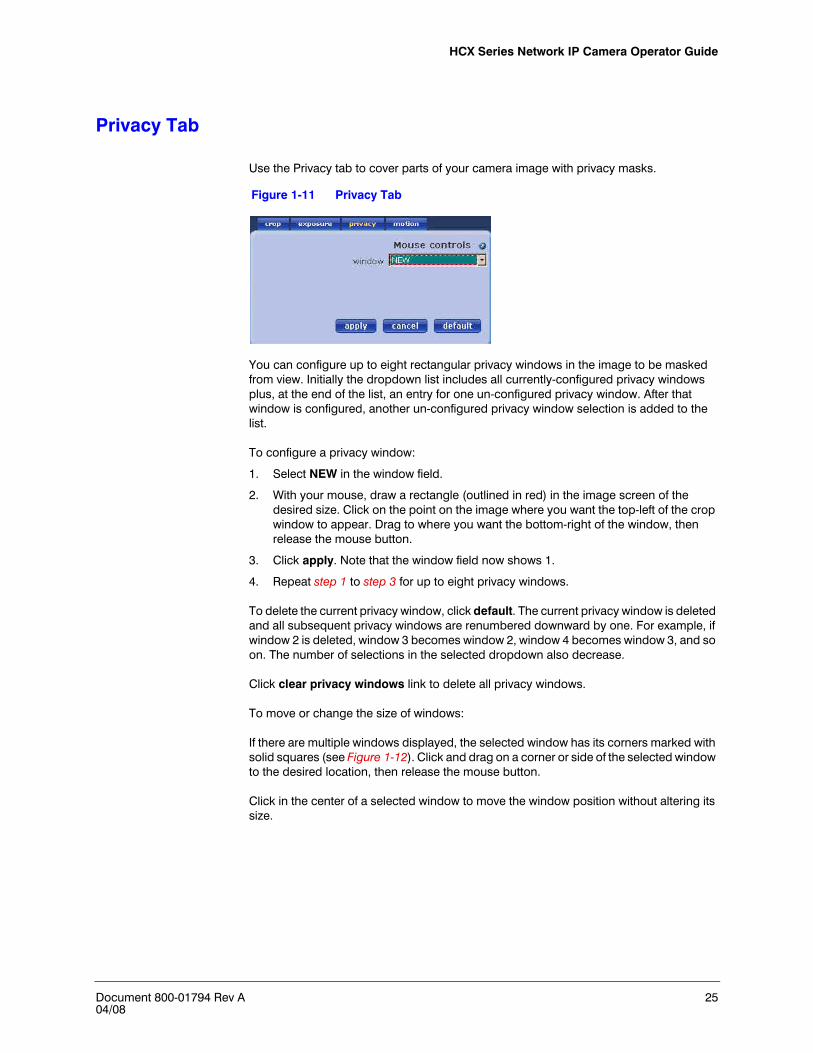
Use the Privacy tab to cover parts of your camera image with privacy masks.
Figure 1-11 Privacy Tab
You can configure up to eight rectangular privacy windows in the image to be masked from view. Initially the dropdown list includes all currently-configured privacy windows plus, at the end of the list, an entry for one un-configured privacy window. After that window is configured, another un-configured privacy window selection is added to the list.
To configure a privacy window:
1. Select NEW in the window field.
2. With your mouse, draw a rectangle (outlined in red) in the image screen of the desired size. Click on the point on the image where you want the top-left of the crop window to appear. Drag to where you want the bottom-right of the window, then release the mouse button.
3. Click apply. Note that the window field now shows 1.
4. Repeat step 1 to step 3 for up to eight privacy windows.
To delete the current privacy window, click default. The current privacy window is deleted and all subsequent privacy windows are renumbered downward by one. For example, if window 2 is deleted, window 3 becomes window 2, window 4 becomes window 3, and so on. The number of selections in the selected dropdown also decrease.
Click clear privacy windows link to delete all privacy windows.
To move or change the size of windows:
If there are multiple windows displayed, the selected window has its corners marked with solid squares (see Figure 1-12). Click and drag on a corner or side of the selected window to the desired location, then release the mouse button.
Click in the center of a selected window to move the window position without altering its size.

26
Figure 1-12 Window Screen with 4 Privacy Zones
Motion Detection
Use the Motion tab to configure motion detection on the camera.
Figure 1-13 Window Screen with Motion Detection
The motion detection settings allow you to configure up to eight rectangular windows of the image to be used for motion detection.
After you set up the parameters for these areas, go to the Trigger screen to choose what action your camera will take when motion is detected.
HCX Series Network IP Camera Operator Guide
Document 800-01794 Rev A 2704/08
The motion detection algorithm running on your camera triggers when significant change has occurred to enough pixels in a chosen part of your camera image. The default action is to use all pixels in the image for motion detection. You may change this by configuring one or more windows.
To set a motion window:
1. Select a window to set in the window field.
2. The selected window has its corners marked with solid squares. You may type parameters directly into the text boxes for position and size or you may use your mouse to specify a window. If no window is marked:
a. Click on the point on the image where you want the top-left of the window to appear.
b. Drag to where you want the bottom-right of the rectangle.
c. Release the mouse button.
If a window is marked:
0. Click on a corner or side of a window to move that corner or side.
a. Drag it to the new desired location
b. Release the mouse button.
c. Clicking in the center of a window to move the position of that window without altering its size.
d. Start a new window by clicking outside the existing window. The click specifies where the top-left of the window appears. Drag to the bottom-right and release the mouse button.
Setting the Mode
For each window, choose whether its interior is to be included or excluded from consideration by the motion detection algorithm. The algorithm uses every pixel that is in an included window but not in any excluded windows. Red indicates exclude windows. Blue indicates include windows.

28
Setting Threshold Values
For each included box, you must set two threshold values—sensitivity and size.
Table 1-4 Threshold Settings Fields
Field Description
sensitivity Specifies how much a pixel value must change to be considered significant. Sensitivity values range between 0 and 255. Auto (default setting) should be sufficient for most applications.
Auto is high enough to filter out most noise and slight lighting changes, and low enough to detect most motion. If this does not give appropriate detection for your application, select a lower value to increase sensitivity to pixel value changes, or a higher value to decrease it.
Note Setting sensitivity to 255 triggers only with a change between absolute black and absolute white. Sensitivity values under 10 often trigger from imager noise even when no motion is visible to the eye.
size Specifies how many pixels in a box must change (by the sensitivity) so that enough change has occurred to trigger motion detection. Size is given as a percentage of the number of pixels in a box so it has values between 0 and 100.
HCX Series Network IP Camera Operator Guide
Document 800-01794 Rev A 2904/08
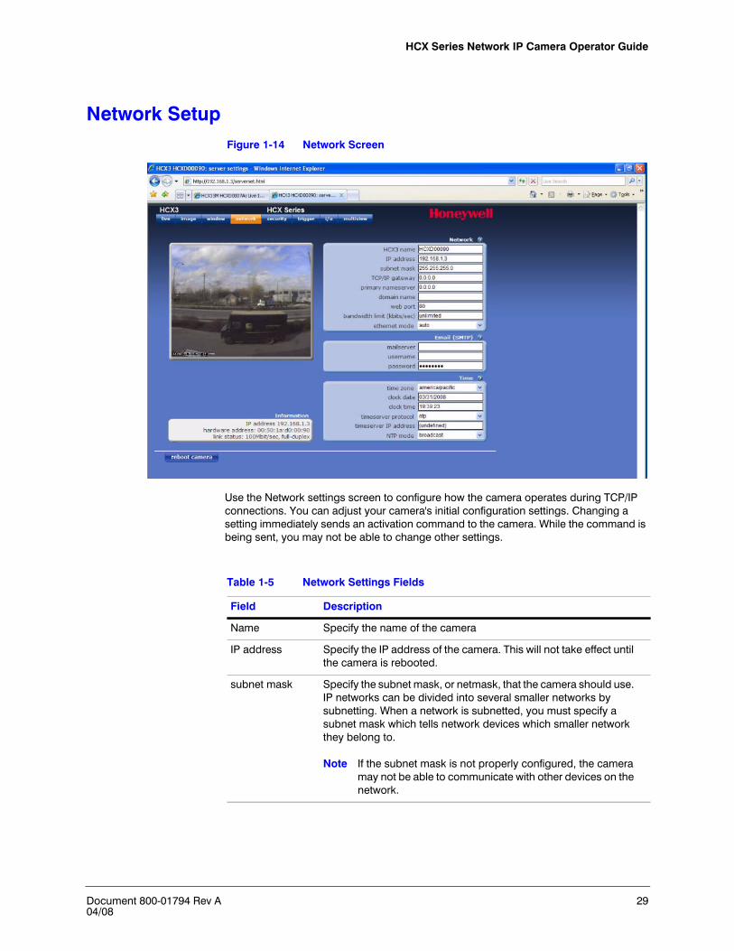
Network SetupFigure 1-14 Network Screen
Use the Network settings screen to configure how the camera operates during TCP/IP connections. You can adjust your camera's initial configuration settings. Changing a setting immediately sends an activation command to the camera. While the command is being sent, you may not be able to change other settings.
Table 1-5 Network Settings Fields
Field Description
Name Specify the name of the camera
IP address Specify the IP address of the camera. This will not take effect until the camera is rebooted.
subnet mask Specify the subnet mask, or netmask, that the camera should use. IP networks can be divided into several smaller networks by subnetting. When a network is subnetted, you must specify a subnet mask which tells network devices which smaller network they belong to.
Note If the subnet mask is not properly configured, the camera may not be able to communicate with other devices on the network.

30
TCP/IP gateway
Enter the IP address of the host to use as a TCP/IP gateway between networks. The gateway allows communication between devices that are on different networks. Without a correct gateway setting, the camera cannot receive or transmit data from/to devices that are not in the same network address range.
primary nameserver
Specify the IP address of the external nameserver (if any) the camera uses when it attempts a TCP/IP connection with another host. An external nameserver must be specified for the camera to access an FTP server by using its text-based name. Since network devices can only recognize numeric IP addresses, a nameserver is needed to resolve the correct numeric IP address from a text-based name used in a connection request.
domain name Enter the domain name for the network that the camera is on. For example, one might enter mycompany.com as the domain name for your camera. The camera appends this suffix to requests that it sends to the nameserver.
web port Enter the desired web port (the port number of your camera's web server). Options: 0 to 65536 (80 is the default).
A camera with a network name of mycam.mycompany.com, and web port 8080, has an URL address of http://mycam.mycompany.com:8080. If its web port is 80, then its url may be abbreviated as http://mycam.mycompany.com.
bandwidth limit Sets the maximum network bandwidth limit in kilobits per second (kbps). Options are:
Unlimited means that image streams are delivered at full speed. This is not a recommended setting as an image stream may take up all the bandwidth in your network.
0 is an alternate method of specifying unlimited.
A non-zero value restricts your camera to that amount of bandwidth. For example, a value of 64 limits the frame rate of your camera so that it outputs no more than 64 kbps of image data each second.
ethernet mode Sets the camera ethernet connection mode. Options are:
Auto (default) autonegotiates the correct setting with the switch.
100full means full-duplex
100half means half-duplex
10full means 100Mbit
10half means 10 Mbit
The setting should match your switch.
Caution Be careful when changing this setting as the incorrect value means you will no longer be able to connect to the camera. Changing this value requires a reboot.
Table 1-5 Network Settings Fields
Field Description

HCX Series Network IP Camera Operator Guide
Document 800-01794 Rev A 3104/08
Setting Email (SMTP)
Use the Email (SMTP) fields to specify an e-mail address where your camera sends notification of trigger events.
Figure 1-15 Email Dialog
Setting the Time
Select the appropriate time zone setting from the pull-down list. Make sure the time zone is correct before you set the clock.
Figure 1-16 Time Dialog
Table 1-6 Email Settings Fields
Field Description
mailserver The name or IP address of an SMTP (Simple Mail Transfer Protocol) server on your camera network. Ensure that it is an SMTP server and that it accepts connections on port 25.
Note For your camera to use a text-based name for connection attempts, you must specify a nameserver.
username The username for SMTP servers which require a logon.
password The password for SMTP servers which require a logon.
HCX13M HCX3/HCX5D

32
Table 1-7 Time Settings Fields
Field Description
time zone Select the time zone where your camera is located
clock date(HCX3/HCX5D)
Adjust the date of your camera, in MM/DD/YY format.
clock time(HDX3/HCX5D)
Adjust the time of your camera in 24 hour format (HH:MM:SS). Before adjusting the clock time, make sure that you have already selected the appropriate time zone for your camera.
timeserver protocol
The timeserver protocol used by your network. Options are:
none means your camera does not obtain its time from the network
ntp (default)
daytime
timeserver IP address
The IP address of the timeserver on your network (if any).
Note Do not enter a DNS name. You may set this to 0.0.0.0. to specify none.
Note When the NTP mode (below) is set to passive, entries in this field have no effect.
NTP mode These items apply only when the timeserver protocol is set to NTP. Options are:
passive enables or disables acceptance of incoming time broadcasts sent by an NTP server on the local subnet.
broadcast (default) enables or disables your camera sending NTP broadcasts to find a time server on your local subnet. If you have set a timeserver IP address, then that is the timeserver used. In this case, a broadcast is sent only if the specified timeserver fails to respond.
both sends out NTP broadcast requests and listens for incoming NTP packets.

HCX Series Network IP Camera Operator Guide
Document 800-01794 Rev A 3304/08
Security SetupFigure 1-17 Security Screen
Setting Passwords
Use the security screen to set up the following passwords:
• When general password protection is enabled, users (up to 2) must enter the general password to view camera images.
• When management password protection is enabled, the management user (limited to one) must enter the management password to modify the default camera settings.
The default usernames are:
• The default username for the General password is login• The default username for the Management password is root. Honeywell
recommends that you change this password when setting up a new camera.

34
Table 1-8 Passwords Fields
Field Description
general protection
Enable or disable password protection for your camera.
change general password
Enter a new general password (up to 7 alphanumeric characters, no spaces). It is recommended that your password contain a combination of numbers and letters to maximize security.
authentication mode
Options are:
basic sends user names and passwords over the network without secure encoding. It allows logging in by a URL address like http://myusername:[email protected].
Basic authentication is less secure since: • Passwords submitted with basic authentication can be
learned by ‘sniffing’ internet traffic. • Many login attempts can be submitted quickly by URLs. • You must close all web browser windows to logout.
Otherwise un-authorized users can access your camera from your computer.
secure authentication encrypts user names and passwords before they are sent over the network. The MD5 encryption standard and a handshaking protocol ensure security. Secure authentication does not allow users to log on by simply specifying their passwords as part of an URL address. For secure authentication to work, you must enable cookies in your web browser.
Note For additional security, Honeywell recommends using secure authentication.
change management password
Enter a new management password (up to 7 alphanumeric characters, no spaces). A password consisting of a combination of numbers and letters works to minimize detection.
Caution The management password cannot be disabled. Users must enter the management password in order to change camera settings.
retype management password
Enter the same password as that entered in the change management password field.

HCX Series Network IP Camera Operator Guide
Document 800-01794 Rev A 3504/08
Setting Access Hours
Use the Access Hours dialog box on the Security screen to limit access to camera images during a specified time.
Figure 1-18 Access Hours Dialog
You can limit access to camera images on weekends or weekdays (or both).
Set weekdays or weekends to on or off to allow or deny access to camera images for the selected days. Alternatively, select timer, then specify the periods during which images are accessible. Enter the start and stop times in 24 hour format (hh:mm). For example, 16:00 = 4 pm, 01:00 = 1 am). During offhours, camera images are accessible only to the management user.
Updating Camera Firmware
To update the firmware, click Browse… to find a firmware file.
Caution It is important that the camera does not lose power during this process. The camera reboots after a successful update.

36
Trigger SettingsFigure 1-19 Trigger Settings Screen
Your camera can capture image sequences in response to trigger events. Captured images can be transferred by FTP and/or e-mail. Possible trigger events include:
• Lapse of periodic intervals• Signals from external relay devices (certain models)• Motion within the image.
Table 1-9 Trigger Settings Fields
Field Description
actions The method by which your camera transfers images in response to a trigger event. Your camera can e-mail individual images, and/or FTP image sequences.
motion Whether detected motion will cause trigger events. When enabled, it is recommended that you also configure motion detection windows within your camera image (see “Motion Detection” on page 26).
Note This item does not apply to all camera models.
external input When enabled, a signal from an external relay device will cause a trigger event.
Note Available on some models only.
HCX Series Network IP Camera Operator Guide
Document 800-01794 Rev A 3704/08
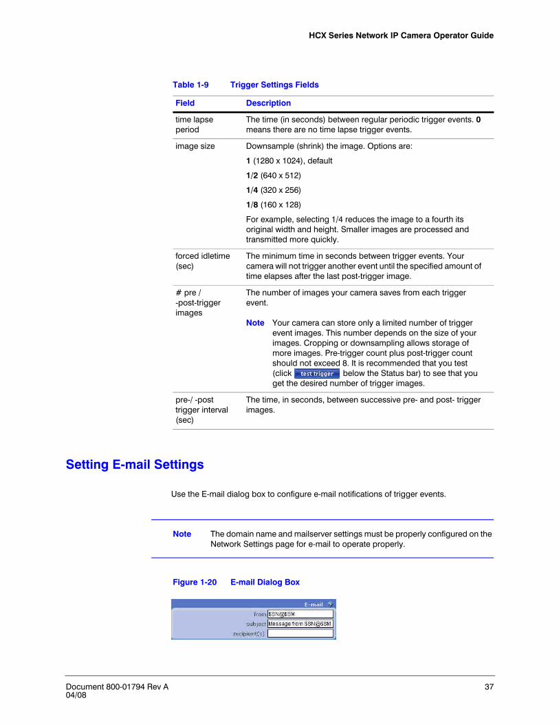
Setting E-mail Settings
Use the E-mail dialog box to configure e-mail notifications of trigger events.
Note The domain name and mailserver settings must be properly configured on the Network Settings page for e-mail to operate properly.
Figure 1-20 E-mail Dialog Box
time lapse period
The time (in seconds) between regular periodic trigger events. 0 means there are no time lapse trigger events.
image size Downsample (shrink) the image. Options are:
1 (1280 x 1024), default
1/2 (640 x 512)
1/4 (320 x 256)
1/8 (160 x 128)
For example, selecting 1/4 reduces the image to a fourth its original width and height. Smaller images are processed and transmitted more quickly.
forced idletime (sec)
The minimum time in seconds between trigger events. Your camera will not trigger another event until the specified amount of time elapses after the last post-trigger image.
# pre / -post-trigger images
The number of images your camera saves from each trigger event.
Note Your camera can store only a limited number of trigger event images. This number depends on the size of your images. Cropping or downsampling allows storage of more images. Pre-trigger count plus post-trigger count should not exceed 8. It is recommended that you test (click below the Status bar) to see that you get the desired number of trigger images.
pre-/ -post trigger interval (sec)
The time, in seconds, between successive pre- and post- trigger images.
Table 1-9 Trigger Settings Fields
Field Description

38
Configuring FTP Settings
Figure 1-21 FTP Dialog Box
Table 1-10 E-mail Fields
Field Description
from The e-mail address from which e-mails will be sent. Recipients see this address in the from field of the e-mails from your camera. You may use dynamic variables in this field (see “Dynamic Variables” on page 41).
subject Recipients see this address in the subject field of the e-mails from your camera. You may use dynamic variables in this field.
recipients The email address(es) of users who will receive e-mails from your camera after trigger events. Separate multiple e-mail addresses by spaces or commas. For example,
[email protected] [email protected]
Table 1-11 FTP Fields
Field Description
FTP hostname The name or IP address of the FTP server to which your camera will transfer trigger images. Enter a hostname of no more than 31 characters.
Note For your camera to use a text (as opposed to ip) hostname, you must specify a nameserver.
username The username that your camera uses to log into the FTP server.

HCX Series Network IP Camera Operator Guide
Document 800-01794 Rev A 3904/08
Checking E-mail and FTP Status
Figure 1-22 E-mail and FTP Status
This status dialog shows either success or the reason for failure of the last e-mail attempt. Test your settings by clicking . One of the following result messages displays in the status area.
E-mail Status—Troubleshooting
password The password that your camera uses to log into the FTP server.
file name The file names of the saved trigger images. You may use dynamic variables in this field (see “Dynamic Variables” on page 41).
Note Images are transferred in JPEG format.
file path The directory on the FTP server where your camera saves trigger images. If this field is left blank, images will be saved in the first directory encountered after logon. Enter a directory name, not a file name.
Note For Unix file systems, a trailing '/' may be required. You may use dynamic variables in this field.
Table 1-11 FTP Fields
Field Description
Result message
Description
Success E-mail sent successfully
No Mailhost No mailserver is specified in the Network Settings page.
File Open Your camera was unable to open the local file. Verify that the file exists and is not corrupted.
Connect Your camera could not connect to the specified mailserver.
Negotiation Your camera could not negotiate SMTP with the specified mailserver. Verify that the specified server is an SMTP server.
Send Your camera could not send the local file.

40
FTP Status—Troubleshooting
This status dialog shows either success or the reason for failure of the last FTP attempt. Test your settings by clicking . One of the following result messages displays in the status area.
Result message
Description
Success File transfer successful
Testing Attempting file transfer
Login Logon failed. The username and/or password is incorrect.
CWD Failed to change to ftp path directory
Send File transfer failed. This is usually due to a network error or it may be that the disk is full.
MKD Failed to create the directory specified in the FTP file path setting. This may be due to lack of permission, a disk-full condition, or an invalid character in the file path.
Memory Your camera ran out of memory. Check memory statistics by telnetting to your camera, then enter show server at the prompt.
Connect Failed to connect to FTP server. Try pinging the server to see if your camera can gain access. Also check the hostname to make sure the name or IP address is valid.
Name resolution
Your camera could not match the FTP hostname to an IP address. Check for correct nameserver and domain name settings on the Network Settings page. Also try pinging the FTP server hostname.
Socket create Your camera could not create a network socket.
Open Failed to open the local trigger file.
1. Telnet to your camera, enter disk cd /ram at the prompt, then press return.
2. Enter disk ls -l, then press return.
Note the names and modification times of any image files in this directory.
3. Enter test trigger input, then disk ls -l again.
Check if these files have updated by comparing their current and past modification times.
Configuration The FTP settings on your camera are misconfigured. Check for missing entries.
None No FTP attempt has yet been made
Command The FTP host did not understand a command sent by the camera.

HCX Series Network IP Camera Operator Guide
Document 800-01794 Rev A 4104/08
Dynamic Variables
Dynamic variables may be used within entries to certain text fields. These variables will be replaced with the appropriate values, as in Table 1-12 below.
Configuring I/O Settings
Use these settings to configure the behavior of the relay output of your camera. To test your relay output configuration, click at the bottom of the screen.
Table 1-12 Dynamic Variables
Result message
Description
$SH The hardware address of the camera
$SI The IP address of the camera
$SN The camera name, as specified on the Network Settings screen (see “Network Setup” on page 29)
$ST The current time, in 08:14:23 format
$SD The current date, in Wed Mar 19 2008 format
$SC Company name (for example, Honeywell)
$SP Product name (for example, HCX13M)
$SV The version of operating software on your camera
$SM The domain name, as specified on the Network Settings screen (see “Network Setup” on page 29)
$FN The name of the file that your camera is accessing
42
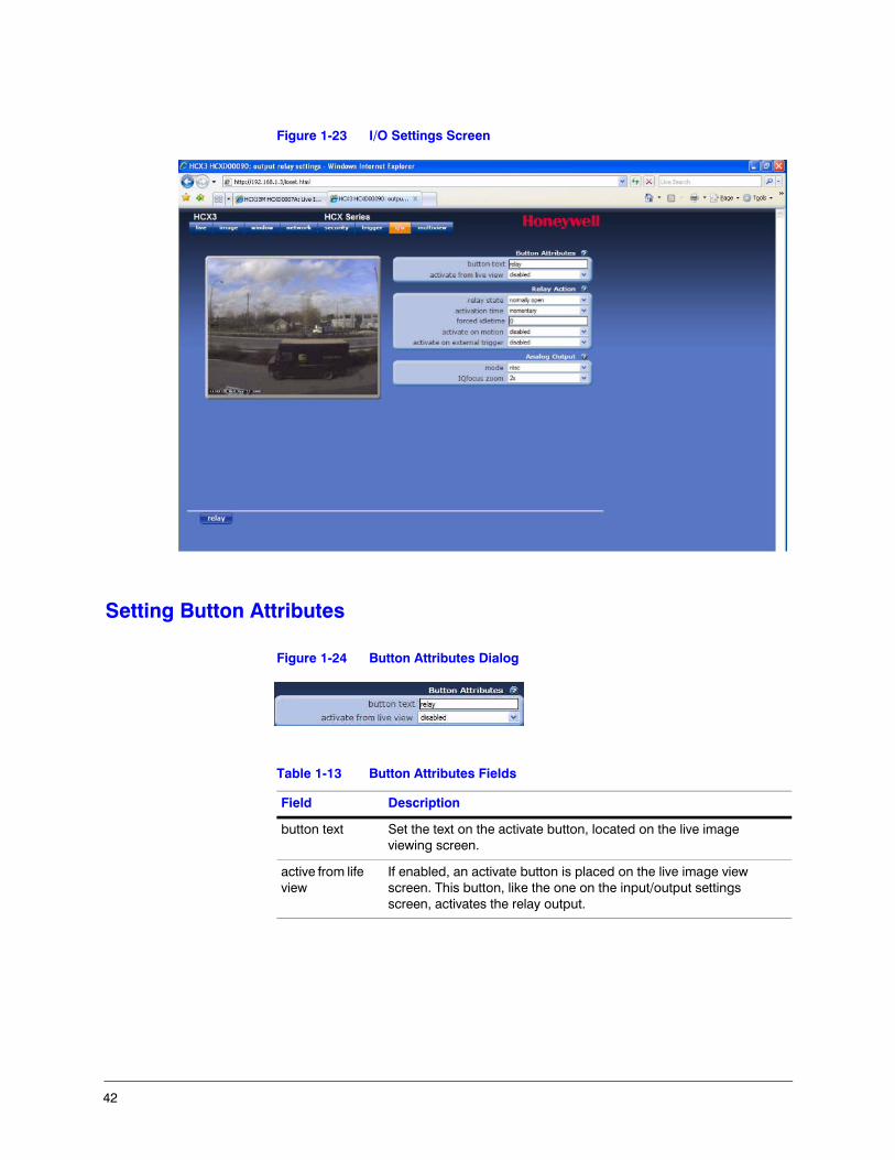
Figure 1-23 I/O Settings Screen
Setting Button Attributes
Figure 1-24 Button Attributes Dialog
Table 1-13 Button Attributes Fields
Field Description
button text Set the text on the activate button, located on the live image viewing screen.
active from life view
If enabled, an activate button is placed on the live image view screen. This button, like the one on the input/output settings screen, activates the relay output.
HCX Series Network IP Camera Operator Guide
Document 800-01794 Rev A 4304/08
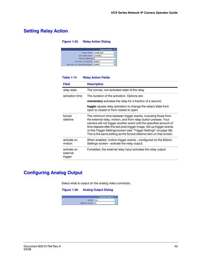
Setting Relay Action
Figure 1-25 Relay Action Dialog
Configuring Analog Output
Select what is output on the analog video connector.
Figure 1-26 Analog Output Dialog
Table 1-14 Relay Action Fields
Field Description
relay state The normal, non-activated state of the relay
activation time The duration of the activation. Options are:
momentary activates the relay for a fraction of a second.
toggle causes relay activation to change the relay's state from open to closed or from closed to open.
forced idletime
The minimum time between trigger events, including those from the external relay, motion, and from relay button presses. Your camera will not trigger another event until the specified amount of time elapses after the last post-trigger image. Set up trigger events on the Trigger Settings screen (see “Trigger Settings” on page 36). This is the same setting as the forced idletime item on that screen.
activate on motion
When enabled, motion trigger events—configured on the Motion Settings screen—activate the relay output.
activate on external trigger
If enabled, the external relay input activates the relay output.

44
Configuring Multiview Settings
Multiview enables you to set up your camera to deliver a web page showing streaming images from up to nine cameras, simultaneously. For each of the nine display areas of that page, you must specify the IP address, port, and label for the camera whose images will show in that display area.
Figure 1-27 MultiView Settings Screen
Table 1-15 Multiview Fields
Field Description
IP address Specify the IP address of the camera. You may use a DNS text name if you have a nameserver on your system.
port Specify the internet port of this display area's camera. Leave this field blank if you are using the default internet port of 80.
label Specify the label shown under the image in this display area. This need not be the name of the camera. You may use up to 31 characters.

HCX Series Network IP Camera Operator Guide
Document 800-01794 Rev A 4504/08
Specifications
Note These specifications refer to all models, except where otherwise noted. Specifications are subject to change without notice.
Table 1-16 Camera Specifications
Specification HCX13M HCX3 HCX5D
Operational
Image Sensor 1/3” CMOS 1/2” CMOS
progressive scan
Video Standard (Analog) NTSC or PAL
Scanning System (Analog)
525/60 lines (NTSC)625/50 lines (PAL)
Minimum Illumination 0.2 lux color 0.3 lux color 0.3 lux color / 0.05 lux B/W
S/N Ratio 50 dB or more (AGC off)
Auto Gain Control (AGC) Peak detect, dark detect, clipaverage, average
Automatic Electronic Shutter (ELC)
1/5–1/10,000 sec
Gamma 0.45
White Balance (AWB) Automatic
Digital Slow Shutter 1X ~ 4X
Analog Video Output 1.0 Vp-p @ 75 Ohms
Motion Detection Multizone Include/Exclude
Exposure Window Include, variable size
Privacy Zones Multiple exclude zones
Electrical
Input Voltage 12 VDC / 24 VAC, PoE IEEE 802.3 af
Input Voltage Range 12–24 VDC, 22–26 VAC
Surge Suppression 1.5 kW transient

46
Power Consumption 2.5 W (max)
IP Specifications
Resolutions 1280 X 1024, HD, SGA, SVGA, 4CIF, VGA, 320 X 256
2048 X 1536, 1600 X 1200, 1280 X 1024, 1280 X 720, 1024 X 768, 4CIF
2560 X 1920, 2048 X 1536, 1600 X 1200, 1280 X 1024, 1280 X 720, 1024 X 768, 4CIF
Frame Rate (NTSC/PAL)
Up to 15 fps @ 1.2 MP, 30 fps @ 4CIF
Up to 12 fps @ 3.1 MP, 30 fps @ 1.3 MP
Up to 10 fps @ 5MP, 12 fps @ 3.1 MP, 30 fps @ 1.3 MP
Video Streaming MJPEG controllable frame rate and bandwidth. Constant and variable bit rate (MJPEG).
Security Multiple user access levels with password protection
Users 1 Administrator, 2 Guests 3 simultaneous unicast
Video access from web browser
Camera live view for up to 3 clients. Full control of all camera settings available to administrator.
Minimum web browsing requirements
Pentium IV CPU 3.0 GHz or equivalent AMD512 MB RAM
AGP graphics card (32 MB RAM)Windows 2000/XP, Internet Explorer 6.0 or later
Supported Protocols IPv4, HTTP, TCP, UDP, FTP, SMTP, ICMP, DHCP, ARP, DNS
Mechanical
Dimensions (W x H x D)
See diagram (Dimensions, page 47)
Weight 0.4 lb (.16 kg) camera only
.8 lb (.36 kg) camera only
Construction Housing: AluminumFinish: Gray painted
Video Output Connector RCA BNC
Other Connectors Power Input: Removable screw terminal blockAlarm I/O: Removable screw terminal block
Network: RJ45 connector
Environmental
Temperature Operating: 32°F to 104°F (0°C to +40°C)Storage: -4° to 140°F (-20°C to 60°)
Relative Humidity 0% to 85%, non-condensing
Regulatory
Table 1-16 Camera Specifications (Cont’d)
Specification HCX13M HCX3 HCX5D

HCX Series Network IP Camera Operator Guide
Document 800-01794 Rev A 4704/08
Dimensions
Emissions FCC, CE (EN55022)
Immunity CE (EN55024)
Safety LVD 2006/95/EC
Table 1-16 Camera Specifications (Cont’d)
Specification HCX13M HCX3 HCX5D
E T H E R N E T8 0 2 . 3 a fP o E
V I D E OO U T
E t h e r n e t H C X 5 D0 0 – 5 0 – 1 A – D 0 – 0 0 – 1 1
P O W E R2 4 V ~ 1 2 - 2 4 V
C F M E D I A
T R I G G E R- I N + - O U T +
P OW E R2 4 V ~ 1 2 - 2 4 V
E T H E R N E T8 0 2 .3 a fP o E V ID E O
O U T
E t h e r n e t H C X 1 3 M0 0 – 5 0 – 1 A – D 0 – 0 0 – 1 1
HCX3 / HCX5D
HCX13M
.71"(18.0 mm)
2.52"(64.0 mm)
2.09
"(5
3.0
mm
)
4.39
"(1
11.5
mm
)3.
96"
(100
.5 m
m)
1.66
"(4
2.3
mm
)
1.26"(32.0 mm)
3.47"(88.1 mm)
1.74"(44.1 mm)
1.66
"41
.8 m
m)
2.91"73.9 mm)
2.91
"73
.9 m
m)

Honeywell Video Systems (Head Office)2700 Blankenbaker Pkwy, Suite 150Louisville, KY 40299, USAwww.honeywellvideo.com℡ +1.800.796.2288
Honeywell Security Australia Pty Ltd.Unit 5, Riverside Centre, 24-28 River Road WestParramatta, NSW 2150, Australiawww.honeywellwsecurity.com/au℡ +61.2.8837.9300
Honeywell Security Asia Pacific33/F Tower A, City Center, 100 Zun Yi RoadShanghai 200051, Chinawww.asia.security.honeywell.com℡ +86 21.2527.4568
Honeywell Security AsiaFlat A, 16/F, CDW Building, 388 Castle Peak RoadTsuen Wan, N.T., Hong Kongwww.asia.security.honeywell.com℡ +852.2405.2323
Honeywell Security FranceParc Gutenberg, 8, Voie La Cardon91120, Palaiseau, Francewww.honeywell.com/security/fr℡ +33.01.64.53.80.40
Honeywell Security Italia SpAVia della Resistenza 53/5920090 BuccinascoMilan, Italywww.honeywell.com/security/it℡ +39.02.48880551
Honeywell Security EspañaMijancas 1. 3a PlantaP. Ind. Las Mercedes28022 Madrid, Spainwww.security.honeywell.com/es℡ +34.902.667.800
Honeywell Video Systems Northern EuropeNetwerk 1211446 WV Purmerend, The Netherlandswww.honeywell.com/security/nl℡ +31.299.410.200
Honeywell Systems GroupAston Fields Road, Whitehouse Ind EstRuncorn, Cheshire, WA7 3DL, UKwww.honeywell.com/security/uk℡ +44 (0)1928 756999
Honeywell Security South AfricaUnit 6 Galaxy Park, 17 Galaxy AvenueLinbro Park, P.O. Box 599042100 Kengray, Johannesburg, South Africawww.honeywell.co.za℡ +27.11.574.2500
Honeywell Security DeutschlandJohannes-Mauthe-Straße 14D-72458 Albstadt, Germanywww.honeywell.com/security/de℡ +49.74 31.8 01.0
Honeywell Security PolandChmielewskiego 22a, 70-028Szczecin, Polskawww.ultrak.pl℡ +48.91.485.40.60
Honeywell Security Czech RepublicHavránkova 33, BrnoDolní Heršpice, 619 00, Czech Republicwww.olympo.cz℡ +420.543.558.111
Honeywell Security Slovakia RepublicVajnorská 142, 83104 BratislavaSlovakiawww.olympo.sk℡ +421.2.444.54.660
© 2008 Honeywell International Inc. All rights reserved. No part of this publication may be reproduced by any means without written permission from Honeywell Video Systems. The information in this publication is believed to be accurate in all respects. However, Honeywell Video Systems cannot assume responsibility for any consequences resulting from the use thereof. The information contained herein is subject to change without notice. Revisions or new editions to this publication may be issued to incorporate such changes.
Document 800-01794 – Rev A – 04/08
www.honeywellvideo.com+1.800.796.CCTV (North America only)