Embed Size (px)
Citation preview
SMC-TR-94-02 AEROSPACE REPORT NO.TR-93(3904)-l
Honeycomb Sandwich Structures: Vented Versus_ ,Unvented Designs for Space Systems
DTICOctober 1993 ELECTE '
MAR1O01994
Prepared by S F
GEORGE EPSTEIN and SUSAN RUTHManufacturing Engineering DepartmentDesign Engineering SubdivisionEngineering and Technology Group
Prepared for
SPACE AND MISSILE SYSTEMS CENTERAIR FORCE MATERIEL COMMAND2430 E. El Segundo BoulevardLos Angeles Air Force Base, CA 90245
Contract No. F04701-88-C-0089
oPrograms Group
Approved for public release; distribution is Unlimited.
(A.) J 00-

This final report was submitted by The Aerospace Corpo;ation, El Segundo, CA 90245-
4691, under Contract No. F04701-88-C-0089 with the Space and Missile Systems Center,
P. 0. Box 92960, Los Angeles, CA 90009-2960. It was reviewed and approved for The
Aerospace Corporation by Dr. J. Meltzer, Corporate Chief Engineer. The project officer is Kurt
Johnson.
This report has been reviewed by the Public Affairs Office (PAS) and is releasable to -.e
National Technical Information Service (NTIS). At NTIS, it will be available to the general public,including foreign nations.
This technical report has been reviewed and is approved for publication. Publication of this
report does not conctitu:. Air Force approval of the report's findings or conclusions. It is
published only for 2'e exchange and stimulation of ideas.
FOR THE COMMANDER
KURT A. O1--HNSO, MIAJOR, USAFCHIEF, SYSTEMS ENGINEERING DIVISION

UnclassifiedSECURITY CLASSIFICATION OF THIS PAGE
REPORT DOCUMENTATION PAGEla REPORT SECURrTY CLASSIFICATION 1b. RESTRICTIVE MARKINGS
Unclassified2, SECURITY CLASSIFICATION AUTHORITY 3. DISTRIBU'iON/AVAILABILITY OF REPORT
2b. DECLASSIFICATIONDOWNGRADING SCHEDULE Approved for public release; distribution is unlimited.
4 PERFORMING ORGANIZArION REPORT NUMBER(Si 5. MONITORING ORGANIZATION REPORT NUMBER(S)
TR-93(3904)-1 SMC-TR-94-02
6a. NAME OF PERFORMING ORGANIZATION 6b. OFFICE SYMBOL 7a. NAME OF MONITORING ORGANIZATION
The Aerospace Corporation applicle) Space and Missile Systems CenterAir Force Materiel Command
6c ADDRESS (City State, and ZIP Code) 7b ADDRESS (City State. and ZIP Code)
2350 E. El Segundo Blvd. Los Angeles Air Force BaseEl Segundo, CA 90245-4691 P 0. Box 92960El__ Segundo,_CA_90245-4691 _Los Angeles, CA 90009-2960
8a NAME OF FUNDING/SPONSORING 8b OFFICE SYMBOL 9 PROCUREMENT INSTRUMENT IDENTIFICATION NUMBERORGANIZATION (If applicable)
Soace and Missile Systems CenterAir Force Materel Command .i
8c ADDRESS (City State, and ZIP Code) 10 SOURCE OF FUNDING NUMBERSLos Angeles Air Force Base PROGRAM PROJECT TASK WORK UNITP. 0. Box 92960 ELEMENT NO NO NO ACCESSION NOLos Angeles, CA 90009-2960
11 TITLE (Include Security Classification)
Honeycomb Sandwich Structure: Vented versus Unvented Designs for Space Systems
12 PERSONAL AUTHORiSiGeorge Epstein and Susan Ruth
13a. TYPE OF REPORT 13b TIME COVERED '14 DATE OF REPORT (Year, Month, Day) I5 PAGE COUNT
Final FROM ept 1992 TO Oct1993 Oct 1993 7 2116. SUPPLEMENTARY NOTATION
17. COSATI CODES 18. SUBJECT TERMS (Continue on reverse if necessary and identity by block number)
FIELD GROUP SUB-GROUP Honeycomb sandwich; Venting: Space systems applications Internal pressureSkin-to-core bonds; Payload fairings; Solar array substrates; Flight failures; Testfailures.
19. ABSTRACT (Continue on reverse if necessary and identify by block number)
Several space systems programs have experienced significant anomalies associated with failures of unvented honeycombsandwich structures. Based on documentation and personal experience, this report provides descriptions of the structures in-volved, the circumstances of the failures, and corrective actions. Of special note, it is Concluded that failures occur due tointernal pressure when the external environment is reduced in ambient pressure. Such failures are initiated at weak bond areas(presumed to result from a manufacturing "defect" - areas that were riot previously identified/repaired. Once initiated, separa-tion of the skin-to-core bond propagates very rapidly and has been described as "expiosive,"
It is recommended that honeycomb structures for space systems be adequately vented whenever possible In situations whereventing is not feasible, a series of recommendations is presented to minimize the likelihood of failure. Design and manufactur-ing parameters are listed for honeycomb sandwich panels that are not fully vented, in order to reduce the likelihood of failure.
20 DISTRIBLTION/AVAILABILITY OF ABSTRACT 21 AeSTrAO, S_.UHI I Y CLASSIFICATION
L,.j uNLSSIF1 _DiUNLIMITED bj SAME AS RPT 0 DTIC USERS Unclassified22a NAME OF RESPOfJS1BLE INDIVIDUAL f2,. TELEPHONE (lrclud- A'ea Cone) 22¢ OFCE SYtO,
Kurt Johnson . (310) 363-2132 SDES
)D FORM 1473, 84 MAR 56 APR editbon may De used untI ex.riausted SECURITY CLASSIFICATION OF THIS PAGEAll other vdi-,or- a'e ub dlee n :I i ifi

FOREWORD
The causes of failure or other anomalies generally can be described as:
• Incorrect design-service test conditions exceed design limitations0 Selection of the wrong material• Inadequate material, process, or part specification• Improper implementation of the specification• Defective material-specification deficient• Processing error-poor workmanship* Inadequate quality control/inspection
The goal of every program is to minimize these problems so as to prevent failures/ano-malies. One important way to accomplish this end is to be aware of previous problems and theirresolutions/prevention strategies. This report is intended to provide such information as related tohoneycomb sandwich structures as used in space systems.
Accesicn For......
NTIS c'-&Df IC 7q -U)By .... .
................. ..............
Dist ..
IA,
CONTENTS
1. INTRODUCTION ........................................................... I.............. 5
2. DEFINITIONS ............................................................................. 7
3. HISTORTCAL BACKGROUND ......................................................... 9j
3.1 Mariner 3.................................................................................. 93.2 TitanlIII.....................................................................................I113.3 Global Positioning System................................................................. 133.4 Atlas-Centaur Payload Fairings............................................................ 13
4. CONCLUSIONS AND RECOMMENDATIONS ..................................... 19
REFERENCES ................................................................................... 21
3

FIGURES
1. Vented versus Unvented Honeycomb Structures................................. 7
2. Fiberglass Payload Fairing.................. ...... 15
3. Spare Payload Fairing,- Uncapped Half Inner Skin Debond........................ 16
4. Typical Relationship Between Skin-to-Core Bond Strength and
Test Temperatures..............................................................18
TABLES
I. Characteristics of Failed Honeycomb Structure.................................. 10
2. Parameters for Reducing Likelihood of Fai*ure in Not Fully
Vented Honeycomb Panels.................................. I................... 20
4

1. INTRODUCTION
Honeycomb sandwich structures are used in a wide variety of critical structures in Air
Force space s, ,tems. These include payload fairings (shrouds) for launch vehicles, adapters for
mounting of satellite payloads, solar array substrates, antennas, ard equipment platforms.
Since 1964, there have been several known or suspected failures of honeycomb structures.
These failures have been attributed to the lack of venting in the panel design'manufacture. On the
other hand, based on available information, vented honeycomb sandwich panels never have
experienced tailure during flight. Ili the cases documented herein, the consequences of the failures
have been significant and costly.
Honeycomb sandwich panels that are not vented will contain air (and possibly volatiles,
including moisture) which causes a pressure differential during launch into orbit. If heating also is
involved, the internal pressure will rise further. In any case, each individual unvented honeycomb
cell acts as a tiny pressure vessel imposing stresses on the skin-to-core bonds. If these stresses are
high enough, panel failure (i.e., skin-to-core debonding) will occur. Certain defects introduced
during panel manufacture would make failure more likely.
This report is intended to document the known anomalies associated with unvented
honeycomb sandwich structures. Because the consequences of such failures can be extremely
severe (e.g., loss of mission and cost'schedule impacts), it is important to understand how such
occurrences can be prevented.
Key factors affecting sensitivity to fabrication defects (i.e., the "robustness" of the design
and manufacturing process) have not been determined. However, based on the documented
information, it is possible to offer observations and concomitant recommendations. Further, it is
advisable to identify the design/manufacturing parameters that are critical in cases in which
unvented designs are considered necessary.
5

2. DEFINITIONS
A honeycomb sandwich structure is composed of a honeycomb core bonded to facings
(skins).
Vented honeycomb sandwich structures use perforated. slotted, or porous honeycomb
cores through which air can flow readily from cell to cell at a rate corresponding to the pressure
drop during the ascent phase of a launch vehicle. Venting to the exterior is provided either through
the skin or panel edge members. The changes in pressure within the panel ideally should occur at a
rate corresponding to the external atmospheric pressure change during launch vehicle ascent.
An unvented honeycomb sandwich structure uses an unvented core (so that there is no all
transfer from cell to cell) anct'or does not provide for venting to the exterior of the panel. The use
of a perforated honeycomb core by itself does not pro,':e a vented structure; the panel must
provide exterior venting as well.
Partially vented honeycomb structures provide some venting but not sufficient to
accommodate the pressure differential, so some internal pressure is developed during ascent.
Larger panels are more likely to be partially vented.
These conditions are illustrated in Figure 1.
Vented Unvented
(perforated core and vents to the exterior)
A As fabricated Air
Apply heat and'orvacuum; air expandsand applies pressureto bonded joint.
II AirPressure can causedebonding if unvented. Air
Figure 1. Vented versus Unvented Honeycomb Structures
7

3. HISTORICAL BACKGROUND
Table I describes the salient characteristics of honeycomb structures that are considered to
have failed due to lack of venting. The following discussion is intended to review the
circumstances related to each of these failures, including the findings from the various
investigations that were reported.
3.1 MARINER 3
A fiberglassiphenolic honeycomb structure was used for the payload fairing for the
National Aeronautics and Space Administration (Jet Propulsion Laboratory) [NASA(JPL)] Mariner
3, launched in 1964.
Anomalies observed in the acceleration rate gyro and fairing internal pressure data
suggested that the Mariner 3 fairing failed at T + 103 sec (Ref. I). Conditions at that time were:
altitude, 95,000 ft; velocity, 4500 ft'sec; fairing maximum surface temperature, 600'F.
Subsequent grc.Lnd tests verified that the failure was attributed to "a pressure buildup in the
fiberglass honeycomb core." (For Mariner 4, the payload fairing was redesigned using 0.090-in.
tick magnesium-thorium alloy.)
Of special note, prior to flight a series of tests had been conducted to verify the original
honeycomb design. These consisted of independent exposures to the predicted in-flight
temperature and pressure environment-but not the combined pressure.'temperature environment.
,-,fter the flight failure. test panels were subjected to the combined environment. Failure occurred
when an internal pressure of 26 psi and a surface temperature of 660'F were recorded. Another
panel was tested with 0.03-in. diameter vent holes, drilled on 1.25-in. centers in the outer surface.
This panel successfully withstood the combined temperature and altitude environment. However,
a panel vented in this manner, but exposed to high humidity. failed at T + 106 sec when tested. (It
is not known whether failure occurred because ,he venting was not sufficient to accommodate the
additional pressure buildup due to the steam generated, or due to a defect in the panel.)
9

Table 1. Characteristics of Failed Honey comb Structure
Program Application Desigs Considerations Remarks
Skins .%dhesi~e Core
Manner 3 Pa~ load fairing 0.020-tn, -lass.iphenolic HT-431 HRP. 1 16 i. Both &urfaccs0.040-in, glass. phenolic (erx" rheflolic) tglzss phenolici painted. Tma\
(predicted) 675*F
Titan III Payload fairing 0.023.-in. glass, phenolic HT-435 HRP, ' S in., Surfaces unpainted.(epoxy phenome) (glass phenolic) Tmax (predicted).
56062O0 F
GPS Solar arra\ three plies. graphire ep.-u. FM-24 Aluminum.substrates (Kapion trn) on one skin) iepox\ perforatei
Atlas-Centaur Pa~lh dd fair-ing fin~e plies. class phenolic boutcr skim HT-424 HRP. 1 8 in.* Scaled skinsfour plies, glass, cptos kinner skin) (eposyphenoiic) k(class phenolic)
*Cell size (diameter of inscribed circle)
A full-scale flight fairing was tested successfully under vacuum conditions only (no
simulated aerodynamic heating). However, when it wvas exposed to the combined environment,
failure occurred at T + 110 sec, at which time the surface temperature was 450'F. T1he test fairing
failed suddenly and extensively in a manner that was described as "explosive." The apparent
cause was separation (debonding) of the inner skin, resulting in inward collapse of the entire
structure.
Flatwise tensile tests (2- x 2-in, specimens) were conducted (Ref. 1) to determine the skin-
to-core bond strength. Values averaged 220 psi at room temperature, ranging from 180 to 252) psi
(three test specimens). Two tests conducted at 400TF gave values of 87 and 94 psi. (The panels
were cut from a production fairing which had a curvature radius of 37.5 in.; hence, the values
measured are expected to be lower than those obtained from standard flat panels.) Note that the
stresses developed due to internal pressure sources are substantially lower than the skin-to-core
(flarwise tensile) strengths, even at elevated ternpetature. From this, wve can conclude that the
panel failures probably were due to defects that escaped inspection, combined with thle internal
pressure.
Peel tests (climbing drum, per ASTM D- 178 1) of samples cut from a payload fairing led
to the conclusion that the peel strength "was reasonably close to that which would be expected for
the honeycomb sandwvich material used in the flight shrouds" (Ref. I ). Values ranged between 3.4
and 4.5 lb/in, width.
10

Perneabilitv tests also were conducted of the honeycornb core. When subjected to
vacuum conditions. pressure decay in the core was 9.6 torr'min parallel to the nohon direction. and
2. torrimin perpendicular thereto. From this it was concluded (Ret. 1) that the rate at which air
permeated the hon,'conb (cell-to-cell) "was insignificant as compared with the AP which would
be experienced during ascent through the atmosphere." This means that rhere would be a
pres.sure differential within the core. unless each cell were vented to the exterior thr-ougih a skin.
To effect a %ell- vented structure using vent holes along the panel edges would require vent holes
(or slots) in one or more of the walls between the individual honeyconb cells.
Based on the results of acoustic fatigue tests. JPL (Ref. 1) concluded that "a,.oustical
excitation did not significantly contribute to the structural failure of the flight shroud."
Some of the conclusions from this extensive test program are particularly noteworthy:
a- The fiberglass/phenolic honeycomb cell-to-cell venting is insignificant compared tothe pressure decay expected in flight.
b. Perforation (venting) of the skin would significantly reduce the pressure differentialand wouid allow the shroud to survive flight.
c. Moisture within the honeycomb cells can add to the pressure differential, especiallyif heated.
3.2 TITAN III
In 1966, a group of satellites was to be launched by a Titan launch vehicle using a
fibergiass phenolic honeycomb sandwich payload fairing. During launch. the fairing expioJed
resulting in loss of all satellites. A remaining fairing of this type, already fabricated, was modified
by drilling vent holes throughout the skin to permit venting. (Subsequently, a major pro.ram was
undertaken to redesign the payload fairing so as to avoid the use of honeycomb sandwich
construction.)
Because of concerns related to the Mariner 3 failure, tests were conducted to assess the
Titan III payload fairing. A series of seven test panels was conditioned in a humidity chamber and
then subjected to combined temperature and altitude environment. One panel failed, with the outer
skin separating "explosively" from the core. At the time of the failure. T + 105 sec, conditions
were: outer skin temperature, 700'F: aftitude. 200,000 ft; and peak heat flux. 5.5 Btu'sec. (Interna!
pressure was not measured.)
11
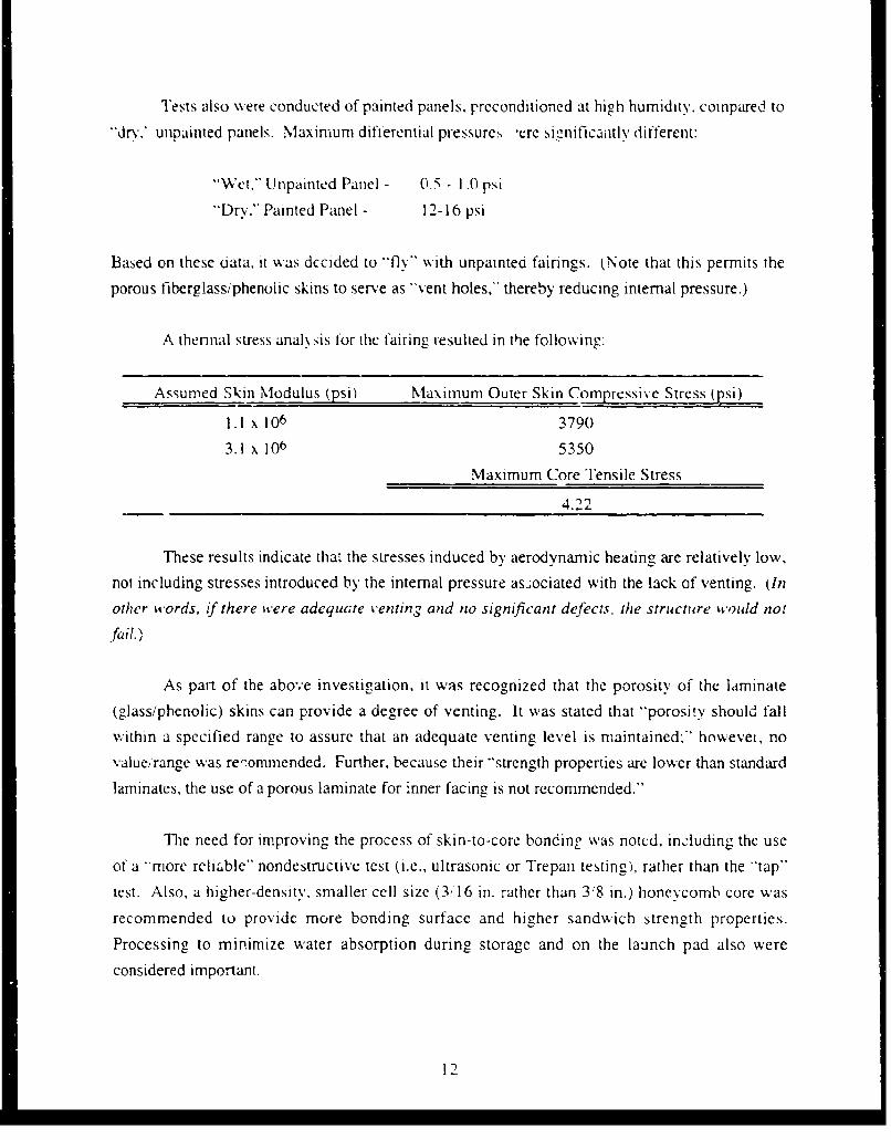
Tests also w.vete conducted of painted panels. preconditioned at high humidity. compared to
"dr' unpainted panels. Maximun differential pressure:, -ere significantlv different:
"Wet." Unpainted Panel - 0.5 - 1 .0 psi
"Dry," Painted Panel - 12-16 psi
Based on these diata, it was decided to fly" with unpainted fairings. (Note that this permits the
porous fiberglassiphenoiic skins to serve as "'vent holes," thereby reducing internal pressure.)
A thennal stress analh sis for the fairing resulted in the following:
Assumed Skin Modulus (psi) Maximum Outer Skin Compressive Stress (psi)
1.1 x 10⁶ 3790
3.1 x 10⁶ 5350
Maximum Core Tensile Stress
4.2.
These results indicate that the stresses induced by aerodynamic heating are relatively low,
not including stresses introduced by the internal pressure as.sociated with the lack of venting. (In
other words, if there were adequcte venting and no significant defects, the structure would no!
.fail.)
As part of the above investigation, it was recognized that the porosity of the laminate
(glass/phenolic) skins can provide a degree of venting. It was stated that "porosiy should fall
within a specified range to assure that an adequate venting level is maintained;" howevei, no
value/range was recommended. Further, because their "strength properties are lower than standardlaminates, the use of a porous laminate for inner facing is not recommended."
The need for improving the process of skin-to-core bonding was notcd, including the use
of a "more reliable" nondestructive test (i.e., ultrasonic or Trepan testing), rather than the "tap"
test. Also, a higher-density, smaller cell size (3!,16 in. rather than 3.8 in.) honeycomb core was
recommended to provide more bonding surface and higher sandwich strength properties.
Processing to minimize water absorption during storage and on the launch pad also were
considered important.
12

3.3 GLOBAL POSITIONING SYSTEM
For the Block 1I Global Positioning System (GPS) satellite. Rockwell International (RI),
Seal Beach. California elected to design the solar array substrates using an unvented honeycomb
design. (Block I used vented honeycomb panels.) The rationale was related to possible
outgassing into the Space Shuttle cargo bay. Thin graphite/epoxy skins (three plies) were
precured; one skin incorporated a thin Kapton film dielectric (to provide the surface to which the
solar cells later would be attached). The skins were bonded to aluminum honeycomb core using a
modified epoxy film adhesive.
In 1983, after RI finalized its stress and thermal analysis, there was a concern over the
adequacy of tae unvented design. Accordingly, to verify this design, RI conducted a thermal-
vacuum development loads test on a panel. The panel ruptured during thermal cycling, and failure
oc :urred at the skin-to-core bond. Interestingly, the failure occurred at the bond to the thinner skin
(without Kapton film). As a result. RI decided to change to a vented honeycomb design and use a
higher-temperature-resistant film adhesive. FM-300, in place of FM-24.
Inadvertently, a number of panels were made using nonperforated unvented honeycomb
core for the outboard solar arrays. During the thermal-vacuum qualification test in October 1985,
one such panel ruptured before completion of the first thermal cycle while it was being heated to
150'C. In December 1985. a second panel was tested and failed just after reaching 150'C. (As a
matter of interest, during attachment of solar cells, it was noted that these panels behaved
differently than the usual solar array substrates. Apparently, deformation of the panel surface
occurred due to internal pressure rise during processing operations.)
Subsequently, these pancls were scrapped, and the required solar array panels were
remanufactured using vented honeycomb core and the FM-300 adhesive, with the panels vented
along the edges.
3.4 ATLAS - CENTAUR PAYLOAD FAIRINGS
In April 1987, General DynamicsFort Worth conducted an "altitude" proof test ci the AC-
58 payload fairing intended as the "backup" for the AC-68 payload fairing that was to be used
during launch of the FLTSATCOM F-8 spacecraft. (Note that. because of discrepancies
previously observed, the AC-58 fairing had been dispositioned as "hold for Engineering Test.")
The proof lest had been introduced due to an anomaly that occurred several years earlier (1981)
13

during launch of the FLTSATCOM -- spacecraft, at that time, it was postulated that the payload
fairing (AC-59) may have exploded (disbonded) during ascent. causing extensive damage to the
spacecraft. The "altitude" proof test consists of placing the structure (actually one-half of the
fairing which is made in two halves) in a chamber and pumping down to simulate an altitude of
90,000 ft.
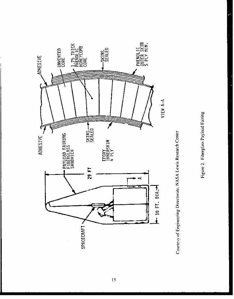
Figure 2 (from Ref. 2) shows the construction, consisting of a four-ply glass/epoxy inner
skin and a five-ply glas&/phenolic outer skin, bonded with HT-424 film (tape) adhesive to 1.75-in.
thick HRP (glass:'phenolic) honeycomb core of 3'8 in. cell size.
During the proof test of the AC-58 payload fairing. it exploded. High-speed motion
pictures recorded the event. There was a small blisterlike separation observable in one frame,
followed by rapid growth of an apparent disbond and explosive separation of the inner skin-to-core
bond, accompanied by extensive fracture of the inner skin (see Figure 3; from Ref. 2).
Investigation indicated that the failure initiated in an area in which there had been a weak
bond, i.e.. there was no imprint from the core on the adhesive film. However, no discrepancies
had been noted (i.e., no voids observed) in this particular area, based on numerous sonic ("tap")
tests. (Many other areas had been found defective and were repaired by injecting a liquid epoxy
resin to fill the discrepant/debonded areas.) Various possible causes were postulated for the"weak-bond" area:
a. Contamination of core or adhesive film surfaces
b. Inadequate flow of adhesive during cure
c. Cwie pressure and'or temperature too low (affects adhesive flow and contactbctween core cell walls and skins)
d. Poor contact between mating surfaces
I. Poor fit2. Cure pressure too low
Particularly noteworthy. the 'tap" inspection had failed to detect the discrepancies in both
AC-58 and AC-59 ltiring failures; and both fairings had similar designs. processing, including
nonvented honeycomb construction.
14
L.) .)-a
7_-J
I--.
-J CDLAJ
-LL I ;-- u ' LI=LL)-
C) = C: C:-
V)JC/ U
U- r.-Iahr =
0- UL V
Ln L
LU.
4-, ed~c
V)

LUJ
LU)
C C
CL,
C D
C) C
LUL
L=D
p.-I-
U lLU.
tzt:I- L/d
~0LLJ'- 16

In the recovery effort, it was decided to apply additional cork insulation on the exterior to
reduce the glueline temperature and to conduct an overpressure proof test of the AC-68 payload
fairing intended for flight. It was noted also that there had been improvements in the materials and
processes for fairings produced after AC-59, i.e., for AC-60 and beyond. A thicker adhesive film
was introdticed, and more attention was paid to processing details and controls. Also the inner
skin was increased from three to four plies.
The augmented overpressure, ambient-temperature, proof test was implemented
successfully for the AC-68 payload fairing. The maximum expected pressure during flight was
calculated to be 16.1 psi, allowing for pressure rise due to heating to 155°F at the bondline.
Allowance also was made for bond strength reduction (8%) at elevated temperature (155°F).
1.3 psi; water partial pressure saturated at 155°F, 0.8 psi; and instrumentation error (5%), 0.9 psi.
Accordingly, the overpressure proof test was conducted at ambient room temperature by
pressurizing internally to 19.1 + 0.5/-0.0 psi using GN 2 . (Subsequently the AC-68 payload
fairing, with additional cork insulation on the exterior, was used successful!y to help launch the
FLTSATCOM F-8 satellite into orbit.)
For applications which involve elevated-temperature exposure, the reduction in bond
strength is an important factor to be considered. For example, see Figure 4 which was used in
establishing the overpressure allowances for the AC-68 payload fairing. Inasmuch as the
overpressure proof test was conducted :.t ambient room temperature, the internal pressure applied
was increased by a finite amount to accommodate the reduction in bond strength that would be
expected at the maximum temperature during ascent.
In conducting the overpressure proof test, it was necessary to know the location of core
splices which could impede GN 2 flow from cell to cell. The HRP core was porous to some
extent, so that it was possible to pressufize selected areas of the payload fairing and achieve
adequate uniformity. For the AC-68 payload fairing, a total of 53 pressurization ports and 14
sensing ports (pressure transducers) were employed. '[he test was conducted in an altitude
chamber which was pumped down to 90,000 ft altitude (14 psid) to reduce the amount of GN 2
pressure required (and reduce the risk of damage to test equipment). The payload fairing was
inspected nondestructively by X-ray and sonic techniques ("tap" test) before and after the
pressurization test.
17

rl--
L LO
0) 0D C'
0)C
a 0
o ZL LA.J U!
C0<CCCc
0 LU C)
/ LLJ
-C-)
00
co
C)f
0
!Sd 'RINBUi-D311TSN~i 3SIMJ.V11
4. CONCLUSIONS AND RECOMMENDATIONS
Unless there is a special circumstance, honeycomb sandwich structures for space systems
applications ghould be designed so that they are vented adequately (i.e., internal pressureessentially follows the exterior pressure environment so that there is practically no pressure
differential). Exposure to high humidity should be avoided if possible or minimized.
In those cases in which venting is not feasible or may be less than optimum, the following
recommendations should be followed:
a. The contractor should conduct an extensive series of development and verificationtests.
b. Assuming such a program is successfully implemented, the fabrication of flightpanels should be monitored by experienced Materials & Processing (M&P)personnel to help ensure that there are no production problems that escapeidentification.
c. Each part should be subjected to proof tests with nondestructive (NDT) inspectionsconducted before and after the tests. These should include exposure to reducedpressure and elevated temperatures, as applicable.
d. Special precautions should be taken to ensure that damage will not occur dunngoperations such as handling, assembly, and so forth. Close surveillance would berequired whenever the panels are not enclosed in well-protected containers.
Table 2 lists the parameters considered important to reduce the likelihood of failure inpanels that are not fully vented. For the most part, these same considerations are appropriate 1, the
design and manufacture of effective honeycomb sandwich structures.
In the event of a marginal or weak skin-to-core adhesive bond, the additional stress due to
internal pressure over and above those normally encountered during launch/flight could serve as"the straw that breaks the camel's back." Especially in a large honeycomb sandwich structure,
there always is the possibility of a localized area with a bond strength substantially below the
average/norm. It is such areas of weak/marginal bond strength that are of concern and can lead to
failure of the entire panel. For unvented honeycomb structures subject to internal pressurization,
once a localized bond failure is initiated, further debonding propagates rapidly, leading to what has
been described as "explosive" failure. Based on the current state of the art, it is not prudent to
19

rely solely on nondestructive testing; proof tests are considered necessary (as discussed above),
particularly if the honeycomb structure , not fully vented so as to ensure no pressure differential
during ascent.
Table 2. Parameters for Reducing Likelihood of Failure inNot Fully Vented Honeycomb Panels
Design Parameters I Manufacturing Parameters
" Smaller cell size * One-step cure,'bonding for laminated skins
• Thickeristiffer skins * Prime core
* Thicker adhesive * Verify fit up of skins and sore
* High pe.--strength adhesive * Verify flow characteristics of adhesive attime of application'cure
" Reduce glueline temperature (external * Apply maximum pressure during cureinsulation)
* Fewer core splices
Note: These same parameters, of course, also can be applied to v ated honeycomb sandwichstructures.
20

REFERENCES
1. Johnson, N. E., "Investigation of Fiberglass Shroud Materials," Technical MemorandumNo. 33-214, Jet Propulsion Laboratory, 1 April 1965.
2. Smith, F. Z., -NASA LeRC Experience with Unvented Honeycomb for Centaur PayloadFairings," presentation at Air Force Space Systems -The Aerospace CorporationWorkshop, 16 December 1987.
21