Embed Size (px)
Citation preview
HON HSV086 Series Safety Shut-off Valves for Efficient, Sustainable and Safe Gas Distribution Proven Technology. Superior Performance.
HON HSV086 Honeywell’s HSV086 series consists of a number
of effective safety shut-off valves for use in gas
transmission systems, gas distribution networks and
industrial gas pressure regulating systems.
The HON HSV086 has demonstrated its quality and
usability for more than 25 years. The HON HSV086
has been improved and modified according to
current technology.
The HON HSV086 series consists of two types of
safety shut-off valves:
• HON HSV086, the standard model with nominal
diameters of 1"-12"
• HON HSVS086, with a two-stage release mechanism
in nominal diameters >16"
Both types offer overpressure and underpressure
protection. The HON HSV086 and HON HSVS086
feature modular construction and are supplied with a
standard control mechanism and sensing element.
Both are suitable for operating pressures up to 100 bar.
Nominal diameters up to 12" are available in pressure
classes up to ANSI 2500.
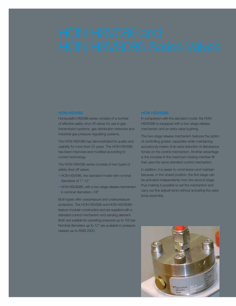
HON HSVS086 In comparison with the standard model, the HON
HSVS086 is equipped with a two-stage release
mechanism and an extra valve bushing.
The two-stage release mechanism features the option
of controlling greater capacities while maintaining
accuracy by means of an extra reduction of disturbance
forces on the control mechanism. Another advantage
is the increase in the maximum closing member lift
that uses the same standard control mechanism.
In addition, it is easier to commission and maintain
because, in the closed position, the first stage can
be activated independently from the second stage,
thus making it possible to set the mechanism and
carry out fine adjustments without activating the valve
body assembly.
HON HSV086 and HON HSVS086 Series Valves Designed to offer overpressure and under pressure protection, the HON HSV086 series from Honeywell (former Gorter brand) comprises safety shut-off valves for use in gas transmission systems, gas distribution networks and industrial gas pressure regulating systems. The HON HSV086 series is supported by Honeywell’s global expertise and unmatched local support capabilities.
Features Low Maintenance Costs • Long maintenance interval because of:
– minimal friction
– minimal number of parts
• Easy to assemble/disassemble:
– valve body remains in line during maintenance
– seat ring is easy to inspect
• The use of economical materials
Modular Construction – separation between sensing element, control
mechanism and valve body assembly
– sensing element(s) and control mechanism(s) are identical for every nominal diameter and pressure class
Special Patented Valve Seat – long maintenance interval due to the erosion-free
enclosure of the seat ring
– bubble-tight even at low temperatures
High Degree of Operational Safety – not sensitive to vibration
– minor dynamic trip mechanism displacement
– single suspension closing member (HON HSV086)
– short safety circuit
High Reproducibility/Accuracy – minimal hysteresis
Emergency Button Closes in Case of – a break in the sensing line
– diaphragm rupture in combination with minimum pressure shut-off
Double Construction – one valve with two control mechanisims, for
safeguarding two pressures
Accessories – various sensing elements/adjusting springs
– closing by remote control
– position indicator on closing member
– open/close sensors on closing member
Clear and Complete Technical Documentation – satisfies current requirements
– available in different languages

Protection Against OverpressureWhen the pressure to be safeguarded (1) in the sensing
element (3) exceeds the maximum value set with the
springs (5) and (6), the diaphragm (2) is pushed
downwards and turns the lever (8) around the pivot
(9). The pin (7) is pushed upwards, turning the balance
(10) to the right side around the pivot (11).
This results in the downward aimed switch pin (18)
eventually stops being supported by the balance (10),
causing the switch lever (16) to turn on its shaft.
This shaft (17) is the supporting point for the closing
member with closing member stem (20). When the
switch lever (16) has rotated a 90° turn, the closing
member (20) closes due to the closing spring (19)
located in the valve body.
In the closed position, the pressure behind the closing
member will be reduced to the outlet pressure. The
pressure difference between inlet and outlet pressure
provides an additional closing force to the closing member
(20). The safety device is now locked. The closing
member will also remain shut even if the safeguarded
pressure (1) drops below the maximum value.
Protection Against UnderpressureWhen the safeguarded pressure (1) in the sensing
element (3) is lower than the trip value set with the
spring (6), the diaphragm (2) shifts upwards.
Using its spring cup (4), the top part of the adjusting
spring (5) comes to rest against the housing of
the control mechanism and no longer against the
diaphragm (2), causing the pressure for switching to
be determined by the spring (6) alone.
The lever (8) will now push the pin (12) downwards,
causing the balance (10) to rotate to the right, just as
when maximum pressure is exceeded. The actions of
the switch lever (16) and the closing member (20) are
similar to those when maximum pressure is exceeded.
The closing member shuts in the same way in the
event of a diaphragm rupture.
Operation HON HSV086 The HON HSV086 safeguards against exceeding a maximum pressure and falling beneath a minimum pressure. The protection against underpressure serves also as a protection against a diaphragm rupture.
safeguarded pressure 1
diaphragm 2
sensing element 3spring cup 4
pin 7
lever 8
pivot 9
balance 10
pivot 11
pin 12
adjusting spring foroverpressure 5
adjusting spring forunderpressure 6
lifting arm 13
relatching device 14
reset button 15
switch lever 16
shaft 17
switch pin 18
spring 19
closing member 20
valv
e b
ody
asse
mb
ly
cont
rol m
echa
nism
sens
ing
elem
ent
Operating Scheme HON HSV086
UnlockingAfter correcting the failure or malfunction and a
pressure equalization across the closing member
(20), the mechanism can only be openend manually.
This is accomplished by pushing down the lifting
arm (13), turning it to the right and simultaneously
pushing the reset button (15). After the mechanism
has been opened, a spring pushes the lifting arm
back into starting position and the relatching device
(14) is disengaged.
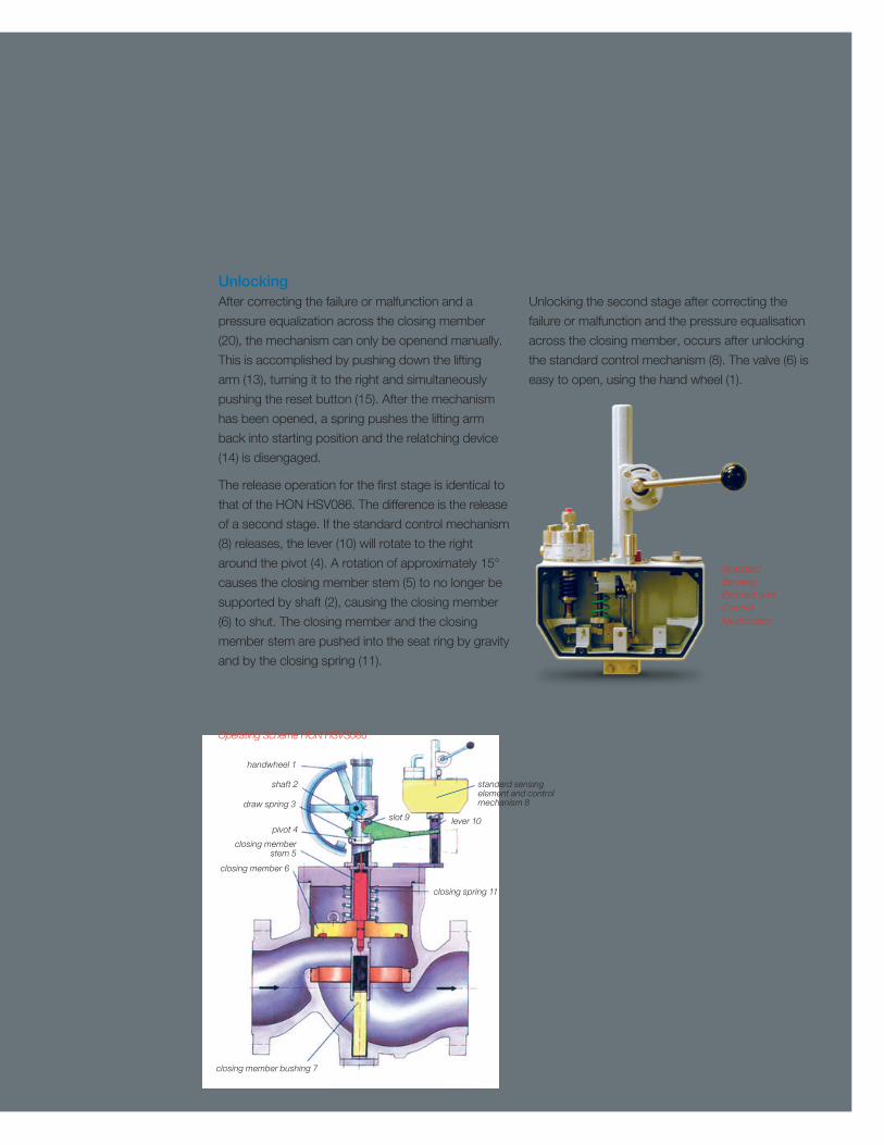
The release operation for the first stage is identical to
that of the HON HSV086. The difference is the release
of a second stage. If the standard control mechanism
(8) releases, the lever (10) will rotate to the right
around the pivot (4). A rotation of approximately 15°
causes the closing member stem (5) to no longer be
supported by shaft (2), causing the closing member
(6) to shut. The closing member and the closing
member stem are pushed into the seat ring by gravity
and by the closing spring (11).
Unlocking the second stage after correcting the
failure or malfunction and the pressure equalisation
across the closing member, occurs after unlocking
the standard control mechanism (8). The valve (6) is
easy to open, using the hand wheel (1).
handwheel 1
shaft 2
lever 10
standard sensing element and control mechanism 8
slot 9
closing spring 11
draw spring 3
pivot 4
closing member stem 5
closing member 6
closing member bushing 7
Standard Sensing Element and Control Mechanism
Operating Scheme HON HSVS086
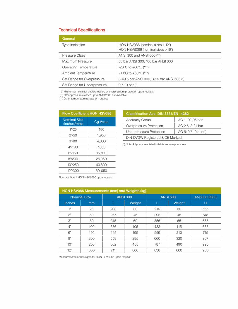
Technical Specifications
General
Type Indication HON HSV086 (nominal sizes 1-12") HON HSVS086 (nominal sizes >16")
Pressure Class ANSI 300 and ANSI 600 (**)
Maximum Pressure 50 bar ANSI 300, 100 bar ANSI 600
Operating Temperature -20°C to +60°C (***)
Ambient Temperature -30°C to +60°C (***)
Set Range for Overpressure 3-49.5 bar ANSI 300, 3-95 bar ANSI 600 (*)
Set Range for Underpressure 0.7-10 bar (*)
(*) Higher set range for underpressure or overpressure protection upon request. (**) Other pressure classes up to ANSI 2500 are available. (***) Other temperature ranges on request
HON HSV086 Measurements (mm) and Weights (kg)
Nominal Size ANSI 300 ANSI 600 ANSI 300/600
Inches mm L Weight L Weight H
1" 26 203 30 216 30 555
2" 50 267 45 292 45 615
3" 80 318 60 356 65 655
4" 100 356 105 432 115 665
6" 150 445 195 559 210 715
8" 200 559 295 660 320 867
10" 250 662 455 787 490 995
12" 300 711 600 838 660 960
Measurements and weights for HON HSVS086 upon request.
Flow Coefficient HON HSV086
Nominal Size (inches/mm) Cg Value
1"/25 480
2"/50 1,950
3"/80 4,300
4"/100 7,050
6"/150 15,100
8"/200 26,060
10"/250 40,800
12"/300 60, 050
Flow coefficient HON HSVS086 upon request.
Classification Acc. DIN 3381/EN 14382
Accuracy Group AG 1: 20-95 bar
Overpressure Protection AG 2.5: 3-21 bar
Underpressure Protection AG 5: 0.7-10 bar (*)
DIN-DVGW Registered & CE Marked
(*) Note: All pressures listed in table are overpressures.
Material Specifications (Standard)
Part Material
Valve Body A352-LCC(QT) or Equal • 1"/DN25: S355 or Equal
Bonnet Flange S355 or A352 or Equal
Valve Plug S355 or Equal
Valve Plug Stem SS
Seat Ring SS
Control Mechanism SS
Diaphragm NBR with Nylon Reinforcement
Dynamic O-rings Viton
Static O-rings NBR
Sensing Element S355 or Equal
Special materials upon request.
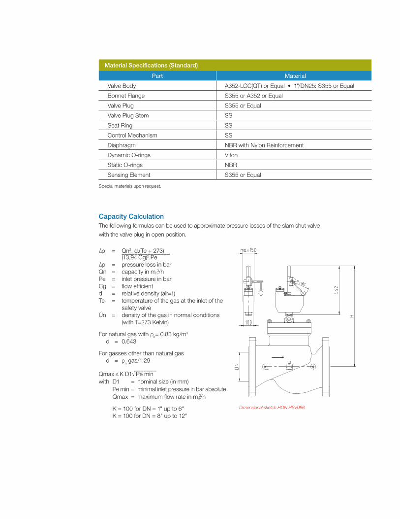
p = Qn2. d.(Te + 273) _______________ (13,94.Cg)2.Pe p = pressure loss in bar
Qn = capacity in mn3/h
Pe = inlet pressure in bar Cg = flow efficient d = relative density (air=1) Te = temperature of the gas at the inlet of the
safety valve Ún = density of the gas in normal conditions
(with T=273 Kelvin)
For natural gas with pn= 0.83 kg/m3
d = 0.643
For gasses other than natural gas
d = pn gas/1.29 _______ Qmax ≤ K D1√ Pe min with D1 = nominal size (in mm) Pe min = minimal inlet pressure in bar absolute Qmax = maximum flow rate in mn
3/h
K = 100 for DN = 1" up to 6" K = 100 for DN = 8" up to 12"
Capacity Calculation The following formulas can be used to approximate pressure losses of the slam shut valve
with the valve plug in open position.
Dimensional sketch HON HSV086

BR-15-42-US 2016-03 ©2016 Honeywell International Inc.
For More Information
To learn more about Honeywell’s
Advanced Gas Solutions, visit
www.honeywellprocess.com or contact
your Honeywell account manager.
Honeywell Process Solutions
Honeywell Bryan Donkin Gas Technologies Ltd.
Enterprise Drive, Holmewood
Chesterfield S42 5UZ, England
Tel: +44 (0)1246 501-501
Fax: +44 (0)1246 501-500
www.honeywellprocess.com