Embed Size (px)
Citation preview

6.0 SIDE WALL BRACING
2xM16
250
TYPE CPortal Column Section
Side Wall Girt
Figure 5.3
4xM16
250
TYPE D & EPortal Column Section (Back)
Side WallGirt
4xM16
250
TYPE D & EPortal Column Section (Front)
Side Wall Girt
Figure 5.4
Figure 5.5
1
2
Numbered in order of assembly.
3
4
Centre RollerDoor Column
C150Reinforcement
Roller Door Channel
StirrupCENTRE ROLLER DOOR
COLUMN
2xM12
90
Double StrapsSingle Strap
Figure 6.0
Figure 5.6
2x
M12
90
INTERNAL ROLLER DOOR COLUMNType A fixing
ShortGirt
InternalRollerDoorColumn
90
140
OR
90
END COLUMNGable End of Homeshed
2xM12
Rear Girt
EndColumn
Vice Grips Step Ladder Tape Measure Spanner Hacksaw Pliers Spirit LevelRivet Gun
5/16” Hex Head Adaptor
Permanent Marker
Caulking Gun ChemicalInjection
Tin Snips Gloves String LinePower Drill
IINNSSTTAALLLLAATTIIOONGUIDEDE
Type E: •8mm Stirrup •Angle Bracket
•4xM16 Threaded Rod with Chemical Injection Anchors
•250mm Embedment •Larger Portal Frame Section
Each stirrup is fixed to the column with four bolts and into the
concrete perimeter beam with four M16 threaded rods with chemical
injection to set anchors. Threaded rods will need to be cut to the
required length before embedding into the concrete.
Embed the rod a minimum of 250mm into the slab.
Threaded rod holes drilled into concrete shall be 18mm diameter.
Centre Roller Door Column Connection:
For Type 2 Gable Homesheds the centre roller door column stirrup
is to be fixed with two M12 chemical capsule anchors at 90mm
concrete embedment.
End Column & Internal Roller Door
Column Connection:
The angle connector is fixed to the column with two bolts and into the
concrete slab with two M12 chemical capsule anchors embedded a
minimum of 90mm into the slab. Drilled holes shall be 14mm diameter
with chemical injection required to set anchors. Depending on the end
column provided, C100 end columns require an angle connector with
length 90mm. C150 end columns require an angle connector with
length 140mm. For internal roller door columns, secure to slab using
the Type A stirrup system previously detailed.
All Homesheds being secured to a concrete slab will require side wall bracing. The size
and quantity of bracing required is indicated in Table 4 which is to be read in conjunction
with the notes below.
Bracing is to be located in individual side bays, directly behind wall girts and screwed to
portal frame columns. All side wall bracing is to be tensioned.
Table 4 - Side Wall Bracing
Eaves Height
(m)
Homeshed
Width (m)
Side Wall Bracing
N1 N2 N3
2.4
3.159 1 x 30x1.0 2 x 30x8.0 2 x 32x1.2
3.921 2 x 30x0.8 2 x 30x1.0 3 x 30x1.0
5.445 2 x 30x1.0 3 x 30x1.0 4 x 30x1.0
6.207 2 x 32x1.2 3 x 30x1.0 4 x 32x1.2
6.969 2 x 32x1.2 3 x 32x1.2 5 x 32x1.2
2.7
3.159 1 x 32x1.2 2 x 30x1.0 3 x 30x1.0
3.921 2 x 30x0.8 2 x 32x1.2 3 x 32x1.2
5.445 2 x 32x1.2 3 x 30x1.0 4 x 32x1.2
6.207 3 x 30x1.0 3 x 32x1.2 5 x 32x1.2
6.969 3 x 30x1.0 4 x 30x1.0 N/A
3.0
3.159 2 x 30x0.8 2 x 30x1.0 3 x 30x1.0
3.921 2 x 30x1.0 2 x 32x1.2 4 x 30x1.0
5.445 3 x 30x1.0 3 x 32x1.2 5 x 32x1.2
6.207 3 x 30x1.0 4 x 30x1.0 6 x 32x1.2
6.969 3 x 32x1.2 4 x 32x1.2 N/A
Notes:
1. 2 x 30x1.0 indicates 2 cross braces from 30x1.0mm (i.e 4 lengths of straps). All braces G300 steel.
2. Braces may be distributed over one or both sides of the shed.
E.g. where 4 braces are required 3 may be on one side and one on the other.
3. All braces to be fixed with two 14-10 self drilling screws at each end.
4. Braces may be doubled in the same bay to provide the correct number of braces e.g:
Type C:
•8mm Stirrup
•2xM16 Threaded Rod with
Chemical Injection Anchors
•250mm Embedment
Each stirrup is fixed to the
column with four bolts and into
the concrete perimeter beam
with two M16 threaded rods with
chemical injection to set anchors.
Threaded rods will need to be
cut to the required length before
embedding into the concrete.
Embed the rod a minimum of
250mm into the slab.
Threaded rod holes drilled into
concrete shall be 18mm diameter.
Concrete Slab Bolted Stirrup With
Angle Connection:
For this application bolted stirrups are to be fixed with four M16
threaded rods with chemical injection, with anchors set at 250mm
concrete embedment.
Type D:
•8mm Stirrup •Angle Bracket •250mm Embedment
•4xM16 Threaded Rod with Chemical Injection Anchors
Each stirrup is fixed to the column with four bolts and into the
concrete perimeter beam with four M16 threaded rods with chemical
injection to set anchors. Threaded rods will need to be cut to the
required length before embedding into the concrete.
Embed the rod a minimum of 250mm into the slab.
Threaded rod holes drilled into concrete shall be 18mm diameter.
5.0 FIXING TO SLAB
TOOLS REQUIRED
MAINTENANCEYour Stratco Homeshed will maintain its good looks for even longer with a simple wash
and wipe down with a soft broom. Stratco Homesheds are produced from the highest
quality materials and will provide many years of service if the important recommendations
set out in the Stratco ‘Selection, Use and Maintenance’ brochure are followed.© Copyright August 2012 14/08/12
Gable HomeshedsFIXING TO CONCRETE SLAB
FIXING TO CONCRETE SLABThese pages are designed to give you the basic assembly techniques to fix your Stratco Gable Homeshed onto a concrete slab.
Please use this installation guide in conjunction with the main set
of instructions “Stratco Gable Homeshed, Framework” supplied
with your Homeshed, as well as the door installation instructions
appropriate to the Type of Homeshed purchased.

Beam Depth‘G’
(Refer table)
100
Perimeter edge beam
Vapourbarrier
Slab mesh
250
35
100slab
35
25
75
35
8LTM200trench mesh wherespecified
50 x 50mm fillet
TYPICAL SECTION THROUGH EDGE PERIMETER BEAM
Figure 2.0Front Gable End
Dimension A
Dim
ensi
on B
Dim
ensi
on C
Dimension D Dimension F = 114mm(C100) = 140mm(C150)
75mmRebate Edge25mm deep
End Column C-SectionC100 or C150mm
Section Thru A
75mmRebate Edge25mm deep
75mm
250mmEdge PerimeterBeam
Dimen
sion
E Dimension E
EDGE PERIMETER BEAM PLAN VIEW
Section Thru B
Figure 1.1Figure 1.0
25
47
28
Section Thru AGABLE END25mm Deep Rebate
75
Slab Rebate
Slab
Section Thru BGUTTER SIDE WALLNo Rebate
75
STANDING THE WALLFigure 3.0
Figure 4
5.0 FIXING TO SLAB
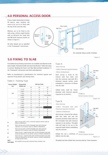
PA DOOR MULLION FIXING
45mmAngleBracket
HexHeadBolt
MasonryAnchor
Wall Girt
Door Lintel
Door Mullion
WallGirt
Figure 5.0
Figure 5.1
2xM12
90
TYPE APortal Column Section
Side Wall Girt
2x
M12
200
TYPE BPortal Column Section
Side Wall Girt
Five bolted stirrup footing connections are available and depend on the
eaves height, Homeshed width and wind classification. Follow the steps
in sections “Building the Frame” and “Rear Wall and Roof Installation” in
the “Framework” instructions and check wall alignment.
Refer to manufacturer’s specifications for chemical capsule and
injection fixing details and setting times.
Table 3 - Footing Type
Eaves Height
(m)
Homeshed
Width (m)
Stirrup Type
N1 N2 N3
2.4
3.159 A A D
3.921 A A B
5.445 A A D
6.207 A B E (C15024)
6.969 D D D
2.7
3.159 A A C
3.921 A B D
5.445 A B D
6.207 B D B
6.969 D E (C15019) Not Suitable
3.0
3.159 A C D
3.921 A D D
5.445 A B B
6.207 D D D
6.969 E (C15015) D Not Suitable
A8mm stirrup with 2x M12 chemical capsule anchor studs at 90mm embedment.
B8mm stirrup with 2x M12 threaded rods with chemical injection to set anchor studs at 200mm embedment.
C8mm stirrup with 2x M16 threaded rods with chemical injection to set anchor studs at 250mm embedment.
D8mm stirrup + angle bracket with 4x M16 threaded rods with chemical injection to set anchor studs at 250mm embedment.
E8mm stirrup + angle bracket with 4x M16 threaded rods with chemical injection to set anchor studs at 250mm embedment & larger portal frame.
NOT
SUITABLENo suitable stirrup with selected frame member size.
Determine the location of the concrete slab.
If the ground is uneven or sloped, ensure that the slope does not
exceed more than 150mm.
1.0 SLAB DIMENSIONS
Table 1 - Slab Dimensions
SizeHOMESHED DETAILS SLAB DIMENSIONS COLUMN LOCATIONS
Width x Length (m) A B C D E
G1 3.159 x 6.207 3.103 6.301 3.045 - 6.823
G2 3.159 x 7.731 3.103 7.825 2.537 - 8.223
G3 3.159 x 9.255 3.103 9.349 3.045 - 9.661
G4 3.921 x 6.207 3.865 6.301 3.045 - 7.186
G5 3.921 x 7.731 3.865 7.825 2.537 - 8.527
G6 3.921 x 9.255 3.865 9.349 3.045 - 9.921
G7 5.445 x 6.207 5.389 6.301 3.045 2.726 8.080
G8 5.445 x 7.731 5.389 7.825 2.537 2.726 9.293
G9 5.445 x 9.255 5.389 9.349 3.045 2.726 10.586
G10 5.445 x 12.303 5.389 12.397 3.045 2.726 13.319
G11 6.207 x 6.207 6.151 6.301 3.045 3.107 8.593
G12 6.207 x 7.731 6.151 7.825 2.537 3.107 9.743
G13 6.207 x 9.255 6.151 9.349 3.045 3.107 10.983
G14 6.207 x 12.303 6.151 12.397 3.045 3.107 13.638
G15 6.969 x 6.207 6.913 6.301 3.045 3.488 9.141
G16 6.969 x 7.731 6.913 7.825 2.537 3.488 10.230
G17 6.969 x 9.255 6.913 9.349 3.045 3.488 11.417
G18 6.969 x 12.303 6.913 12.397 3.045 3.488 13.990
Notes:
1. Width of edge perimeter beam = 250mm.
2. Slab mesh SL72 for beams less then 350mm deep, SL82 for
beams 350mm or deeper.
3. 8LTM200 trench mesh to be used where beams are deeper than
350mm, or where required due to soil conditions
(determined by others).
4. Cover to reinforcement = 35mm, top and bottom, and to slab edge.
5. Concrete Grade N20
6. Slabs suitable for Class A, S, M, M-D sites.
2.0 CONCRETE SLAB PREPARATION If your Gable Homeshed includes
PA door/s, door mullions will
need to be cut to sit flush with
the top of the concrete slab.
Mullions are to be fixed to the
slab using a 45mm angle bracket
with an M10x20 hex head bolt
and M6.0x40 masonry anchor as
shown in Figure 4.
All other details are as specified
in the “Framework” instructions.
4.0 PERSONAL ACCESS DOOR
Concrete Edge Perimeter Beams
Homeshed slabs will require a concrete edge beam around the
perimeter of the entire slab. The edge beam shall be 250mm in
width in all cases with a depth as specified in Table 2. Refer to the
corresponding notes for additional details including slab and edge
beam reinforcing requirements.
Figure 2.0 shows a typical section of an edge beam and slab.
Table 2 - Depth of Edge Perimeter Beam
Eaves Height
(m)
Homeshed
Width (m)
Depth of Edge Perimeter Beam (‘G’)
(mm)
N1 N2 N3
2.4
3.159 200 200 300
3.921 200 200 300
5.445 200 200 300
6.207 200 250 400
6.969 300 300 500
2.7
3.159 200 200 300
3.921 200 250 300
5.445 200 250 300
6.207 250 300 400
6.969 300 300 n/a
3.0
3.159 200 300 300
3.921 200 300 300
5.445 200 300 350
6.207 300 300 400
6.969 300 300 n/a
Figure 1 shows the orientation of the columns and the slab
layout. Table 1 provides slab dimensions and column locations.
Mark out the slab dimensions as specified in Table 1 and
check that the corner to corner measurements are equal.
The outside edge of your slab shall be 75mm from the
outside face of the columns.
If a rebate is required, ensure the top of the rebate begins
inline with the outside face of the columns, see Figure 1.1.
Once the slab has set, mark out column locations (refer to Figure
1.0 & Table 1).
Complete the sections “Constructing the Walls”, “Gutter Installation”
and “Personal Access Door” from the “Framework” instructions. In
addition, refer to the “4.0 Personal Access Door” section of these
instructions if PA door/s are being installed.
Stand the completed wall frame in the positions marked (Figure 3.0)
and temporarily brace.
Repeat for the opposite side wall. Do not remove bracing until
columns are fixed to the concrete.
Important Note: It may be necessary to pre-drill some or all of the concrete anchor
holes before columns are braced in position. If columns interfere
with the drill and do not allow clearance through stirrup holes, mark
and pre-drill required holes to size and depth specified in the “5.0
Fixing to Slab” section of these instructions.
Type A:
•8mm Stirrup
•2xM12 Chemical Capsule Anchors
•90mm Embedment
Each stirrup is fixed to the
column with four bolts and
into the concrete slab with M12
chemical capsule anchor studs
embedded a minimum of 90mm
into the slab.
Drilled holes shall be 14mm
diameter with chemical capsule
required to set anchors.
Type B:
•8mm Stirrup
•2xM12 Threaded Rod with
Chemical Injection Anchors
•200mm Embedment
Each stirrup is fixed to the column
with four bolts and into the
concrete perimeter beam with two
M12 threaded rods with chemical
injection to set anchors. Threaded
rods will need to be cut to the
required length before embedding
into the concrete.
Embed the rod a minimum of
200mm into the slab.
Threaded rod holes drilled into concrete shall be 14mm diameter.
3.0 WALL FRAMES

Beam Depth‘G’
(Refer table)
100
Perimeter edge beam
Vapourbarrier
Slab mesh
250
35
100slab
35
25
75
35
8LTM200trench mesh wherespecified
50 x 50mm fillet
TYPICAL SECTION THROUGH EDGE PERIMETER BEAM
Figure 2.0Front Gable End
Dimension A
Dim
ensi
on B
Dim
ensi
on C
Dimension D Dimension F = 114mm(C100) = 140mm(C150)
75mmRebate Edge25mm deep
End Column C-SectionC100 or C150mm
Section Thru A
75mmRebate Edge25mm deep
75mm
250mmEdge PerimeterBeam
Dimen
sion
E Dimension E
EDGE PERIMETER BEAM PLAN VIEW
Section Thru B
Figure 1.1Figure 1.0
25
72
28
Section Thru AGABLE END25mm Deep Rebate
75
Slab Rebate
Slab
Section Thru BGUTTER SIDE WALLNo Rebate
75
STANDING THE WALLFigure 3.0
Figure 4
5.0 FIXING TO SLAB
PA DOOR MULLION FIXING
45mmAngleBracket
HexHeadBolt
MasonryAnchor
Wall Girt
Door Lintel
Door Mullion
WallGirt
Figure 5.0
Figure 5.1
2xM12
90
TYPE APortal Column Section
Side Wall Girt
2x
M12
200
TYPE BPortal Column Section
Side Wall Girt
Five bolted stirrup footing connections are available and depend on the
eaves height, Homeshed width and wind classification. Follow the steps
in sections “Building the Frame” and “Rear Wall and Roof Installation” in
the “Framework” instructions and check wall alignment.
Refer to manufacturer’s specifications for chemical capsule and
injection fixing details and setting times.
Table 3 - Footing Type
Eaves Height
(m)
Homeshed
Width (m)
Stirrup Type
N1 N2 N3
2.4
3.159 A A D
3.921 A A B
5.445 A A D
6.207 A B E (C15024)
6.969 D D D
2.7
3.159 A A C
3.921 A B D
5.445 A B D
6.207 B D B
6.969 D E (C15019) Not Suitable
3.0
3.159 A C D
3.921 A D D
5.445 A B B
6.207 D D D
6.969 E (C15015) D Not Suitable
A8mm stirrup with 2x M12 chemical capsule anchor studs at 90mm embedment.
B8mm stirrup with 2x M12 threaded rods with chemical injection to set anchor studs at 200mm embedment.
C8mm stirrup with 2x M16 threaded rods with chemical injection to set anchor studs at 250mm embedment.
D8mm stirrup + angle bracket with 4x M16 threaded rods with chemical injection to set anchor studs at 250mm embedment.
E8mm stirrup + angle bracket with 4x M16 threaded rods with chemical injection to set anchor studs at 250mm embedment & larger portal frame.
NOT
SUITABLENo suitable stirrup with selected frame member size.
Determine the location of the concrete slab.
If the ground is uneven or sloped, ensure that the slope does not
exceed more than 150mm.
1.0 SLAB DIMENSIONS
Table 1 - Slab Dimensions
SizeHOMESHED DETAILS SLAB DIMENSIONS COLUMN LOCATIONS
Width x Length (m) A B C D E
G1 3.159 x 6.207 3.103 6.301 3.045 - 6.823
G2 3.159 x 7.731 3.103 7.825 2.537 - 8.223
G3 3.159 x 9.255 3.103 9.349 3.045 - 9.661
G4 3.921 x 6.207 3.865 6.301 3.045 - 7.186
G5 3.921 x 7.731 3.865 7.825 2.537 - 8.527
G6 3.921 x 9.255 3.865 9.349 3.045 - 9.921
G7 5.445 x 6.207 5.389 6.301 3.045 2.726 8.080
G8 5.445 x 7.731 5.389 7.825 2.537 2.726 9.293
G9 5.445 x 9.255 5.389 9.349 3.045 2.726 10.586
G10 5.445 x 12.303 5.389 12.397 3.045 2.726 13.319
G11 6.207 x 6.207 6.151 6.301 3.045 3.107 8.593
G12 6.207 x 7.731 6.151 7.825 2.537 3.107 9.743
G13 6.207 x 9.255 6.151 9.349 3.045 3.107 10.983
G14 6.207 x 12.303 6.151 12.397 3.045 3.107 13.638
G15 6.969 x 6.207 6.913 6.301 3.045 3.488 9.141
G16 6.969 x 7.731 6.913 7.825 2.537 3.488 10.230
G17 6.969 x 9.255 6.913 9.349 3.045 3.488 11.417
G18 6.969 x 12.303 6.913 12.397 3.045 3.488 13.990
Notes:
1. Width of edge perimeter beam = 250mm.
2. Slab mesh SL72 for beams less then 350mm deep, SL82 for
beams 350mm or deeper.
3. 8LTM200 trench mesh to be used where beams are deeper than
350mm, or where required due to soil conditions
(determined by others).
4. Cover to reinforcement = 35mm, top and bottom, and to slab edge.
5. Concrete Grade N20
6. Slabs suitable for Class A, S, M, M-D sites.
2.0 CONCRETE SLAB PREPARATION If your Gable Homeshed includes
PA door/s, door mullions will
need to be cut to sit flush with
the top of the concrete slab.
Mullions are to be fixed to the
slab using a 45mm angle bracket
with an M10x20 hex head bolt
and M6.0x40 masonry anchor as
shown in Figure 4.
All other details are as specified
in the “Framework” instructions.
4.0 PERSONAL ACCESS DOOR
Concrete Edge Perimeter Beams
Homeshed slabs will require a concrete edge beam around the
perimeter of the entire slab. The edge beam shall be 250mm in
width in all cases with a depth as specified in Table 2. Refer to the
corresponding notes for additional details including slab and edge
beam reinforcing requirements.
Figure 2.0 shows a typical section of an edge beam and slab.
Table 2 - Depth of Edge Perimeter Beam
Eaves Height
(m)
Homeshed
Width (m)
Depth of Edge Perimeter Beam (‘G’)
(mm)
N1 N2 N3
2.4
3.159 200 200 300
3.921 200 200 300
5.445 200 200 300
6.207 200 250 400
6.969 300 300 500
2.7
3.159 200 200 300
3.921 200 250 300
5.445 200 250 300
6.207 250 300 400
6.969 300 300 n/a
3.0
3.159 200 300 300
3.921 200 300 300
5.445 200 300 350
6.207 300 300 400
6.969 300 300 n/a
Figure 1 shows the orientation of the columns and the slab
layout. Table 1 provides slab dimensions and column locations.
Mark out the slab dimensions as specified in Table 1 and
check that the corner to corner measurements are equal.
The outside edge of your slab shall be 75mm from the
outside face of the columns.
If a rebate is required, ensure the top of the rebate begins
inline with the outside face of the columns, see Figure 1.1.
Once the slab has set, mark out column locations (refer to Figure
1.0 & Table 1).
Complete the sections “Constructing the Walls”, “Gutter Installation”
and “Personal Access Door” from the “Framework” instructions. In
addition, refer to the “4.0 Personal Access Door” section of these
instructions if PA door/s are being installed.
Stand the completed wall frame in the positions marked (Figure 3.0)
and temporarily brace.
Repeat for the opposite side wall. Do not remove bracing until
columns are fixed to the concrete.
Important Note: It may be necessary to pre-drill some or all of the concrete anchor
holes before columns are braced in position. If columns interfere
with the drill and do not allow clearance through stirrup holes, mark
and pre-drill required holes to size and depth specified in the “5.0
Fixing to Slab” section of these instructions.
Type A:
•8mm Stirrup
•2xM12 Chemical Capsule Anchors
•90mm Embedment
Each stirrup is fixed to the
column with four bolts and
into the concrete slab with M12
chemical capsule anchor studs
embedded a minimum of 90mm
into the slab.
Drilled holes shall be 14mm
diameter with chemical capsule
required to set anchors.
Type B:
•8mm Stirrup
•2xM12 Threaded Rod with
Chemical Injection Anchors
•200mm Embedment
Each stirrup is fixed to the column
with four bolts and into the
concrete perimeter beam with two
M12 threaded rods with chemical
injection to set anchors. Threaded
rods will need to be cut to the
required length before embedding
into the concrete.
Embed the rod a minimum of
200mm into the slab.
Threaded rod holes drilled into concrete shall be 14mm diameter.
3.0 WALL FRAMES

6.0 SIDE WALL BRACING
2xM16
250
TYPE CPortal Column Section
Side Wall Girt
Figure 5.3
4xM16
250
TYPE D & EPortal Column Section (Back)
Side WallGirt
4xM16
250
TYPE D & EPortal Column Section (Front)
Side Wall Girt
Figure 5.4
Figure 5.5
1
2
Numbered in order of assembly.
3
4
Centre RollerDoor Column
C150Reinforcement
Roller Door Channel
StirrupCENTRE ROLLER DOOR
COLUMN
2xM12
90
Double StrapsSingle Strap
Figure 6.0
Figure 5.6
2x
M12
90
INTERNAL ROLLER DOOR COLUMNType A fixing
ShortGirt
InternalRollerDoorColumn
90
140
OR
90
END COLUMNGable End of Homeshed
2xM12
Rear Girt
EndColumn
Vice Grips Step Ladder Tape Measure Spanner Hacksaw Pliers Spirit LevelRivet Gun
5/16” Hex Head Adaptor
Permanent Marker
Caulking Gun ChemicalInjection
Tin Snips Gloves String LinePower Drill
IINNSSTTAALLLLAATTIIOONGUIDEDE
Type E: •8mm Stirrup •Angle Bracket
•4xM16 Threaded Rod with Chemical Injection Anchors
•250mm Embedment •Larger Portal Frame Section
Each stirrup is fixed to the column with four bolts and into the
concrete perimeter beam with four M16 threaded rods with chemical
injection to set anchors. Threaded rods will need to be cut to the
required length before embedding into the concrete.
Embed the rod a minimum of 250mm into the slab.
Threaded rod holes drilled into concrete shall be 18mm diameter.
Centre Roller Door Column Connection:
For Type 2 Gable Homesheds the centre roller door column stirrup
is to be fixed with two M12 chemical capsule anchors at 90mm
concrete embedment.
End Column & Internal Roller Door
Column Connection:
The angle connector is fixed to the column with two bolts and into the
concrete slab with two M12 chemical capsule anchors embedded a
minimum of 90mm into the slab. Drilled holes shall be 14mm diameter
with chemical injection required to set anchors. Depending on the end
column provided, C100 end columns require an angle connector with
length 90mm. C150 end columns require an angle connector with
length 140mm. For internal roller door columns, secure to slab using
the Type A stirrup system previously detailed.
All Homesheds being secured to a concrete slab will require side wall bracing. The size
and quantity of bracing required is indicated in Table 4 which is to be read in conjunction
with the notes below.
Bracing is to be located in individual side bays, directly behind wall girts and screwed to
portal frame columns. All side wall bracing is to be tensioned.
Table 4 - Side Wall Bracing
Eaves Height
(m)
Homeshed
Width (m)
Side Wall Bracing
N1 N2 N3
2.4
3.159 1 x 30x1.0 2 x 30x8.0 2 x 32x1.2
3.921 2 x 30x0.8 2 x 30x1.0 3 x 30x1.0
5.445 2 x 30x1.0 3 x 30x1.0 4 x 30x1.0
6.207 2 x 32x1.2 3 x 30x1.0 4 x 32x1.2
6.969 2 x 32x1.2 3 x 32x1.2 5 x 32x1.2
2.7
3.159 1 x 32x1.2 2 x 30x1.0 3 x 30x1.0
3.921 2 x 30x0.8 2 x 32x1.2 3 x 32x1.2
5.445 2 x 32x1.2 3 x 30x1.0 4 x 32x1.2
6.207 3 x 30x1.0 3 x 32x1.2 5 x 32x1.2
6.969 3 x 30x1.0 4 x 30x1.0 N/A
3.0
3.159 2 x 30x0.8 2 x 30x1.0 3 x 30x1.0
3.921 2 x 30x1.0 2 x 32x1.2 4 x 30x1.0
5.445 3 x 30x1.0 3 x 32x1.2 5 x 32x1.2
6.207 3 x 30x1.0 4 x 30x1.0 6 x 32x1.2
6.969 3 x 32x1.2 4 x 32x1.2 N/A
Notes:
1. 2 x 30x1.0 indicates 2 cross braces from 30x1.0mm (i.e 4 lengths of straps). All braces G300 steel.
2. Braces may be distributed over one or both sides of the shed.
E.g. where 4 braces are required 3 may be on one side and one on the other.
3. All braces to be fixed with two 14-10 self drilling screws at each end.
4. Braces may be doubled in the same bay to provide the correct number of braces e.g:
Type C:
•8mm Stirrup
•2xM16 Threaded Rod with
Chemical Injection Anchors
•250mm Embedment
Each stirrup is fixed to the
column with four bolts and into
the concrete perimeter beam
with two M16 threaded rods with
chemical injection to set anchors.
Threaded rods will need to be
cut to the required length before
embedding into the concrete.
Embed the rod a minimum of
250mm into the slab.
Threaded rod holes drilled into
concrete shall be 18mm diameter.
Concrete Slab Bolted Stirrup With
Angle Connection:
For this application bolted stirrups are to be fixed with four M16
threaded rods with chemical injection, with anchors set at 250mm
concrete embedment.
Type D:
•8mm Stirrup •Angle Bracket •250mm Embedment
•4xM16 Threaded Rod with Chemical Injection Anchors
Each stirrup is fixed to the column with four bolts and into the
concrete perimeter beam with four M16 threaded rods with chemical
injection to set anchors. Threaded rods will need to be cut to the
required length before embedding into the concrete.
Embed the rod a minimum of 250mm into the slab.
Threaded rod holes drilled into concrete shall be 18mm diameter.
5.0 FIXING TO SLAB
TOOLS REQUIRED
MAINTENANCEYour Stratco Homeshed will maintain its good looks for even longer with a simple wash
and wipe down with a soft broom. Stratco Homesheds are produced from the highest
quality materials and will provide many years of service if the important recommendations
set out in the Stratco ‘Selection, Use and Maintenance’ brochure are followed.© Copyright August 2012 14/08/12
Gable HomeshedsFIXING TO CONCRETE SLAB
FIXING TO CONCRETE SLABThese pages are designed to give you the basic assembly techniques to fix your Stratco Gable Homeshed onto a concrete slab.
Please use this installation guide in conjunction with the main set
of instructions “Stratco Gable Homeshed, Framework” supplied
with your Homeshed, as well as the door installation instructions
appropriate to the Type of Homeshed purchased.

6.0 SIDE WALL BRACING
Double StrapsSingle Strap
Figure 6.0
All Homesheds being secured to a concrete slab will require side wall bracing. The size
and quantity of bracing required is indicated in Table 4 which is to be read in conjunction
with the notes below.
Bracing is to be located in individual side bays, directly behind wall girts and screwed to
portal frame columns. All side wall bracing is to be tensioned.
Table 4 - Side Wall Bracing
Eaves Height
(m)
Homeshed
Width (m)
Side Wall Bracing
N1 N2 N3
2.4
3.159 1 x 30x1.0 2 x 30x8.0 2 x 32x1.2
3.921 2 x 30x0.8 2 x 30x1.0 3 x 30x1.0
5.445 2 x 30x1.0 3 x 30x1.0 4 x 30x1.0
6.207 2 x 32x1.2 3 x 30x1.0 4 x 32x1.2
6.969 2 x 32x1.2 3 x 32x1.2 5 x 32x1.2
2.7
3.159 1 x 32x1.2 2 x 30x1.0 3 x 30x1.0
3.921 2 x 30x0.8 2 x 32x1.2 3 x 32x1.2
5.445 2 x 32x1.2 3 x 30x1.0 4 x 32x1.2
6.207 3 x 30x1.0 3 x 32x1.2 5 x 32x1.2
6.969 3 x 30x1.0 4 x 30x1.0 N/A
3.0
3.159 2 x 30x0.8 2 x 30x1.0 3 x 30x1.0
3.921 2 x 30x1.0 2 x 32x1.2 4 x 30x1.0
5.445 3 x 30x1.0 3 x 32x1.2 5 x 32x1.2
6.207 3 x 30x1.0 4 x 30x1.0 6 x 32x1.2
6.969 3 x 32x1.2 4 x 32x1.2 N/A
Notes:
1. 2 x 30x1.0 indicates 2 cross braces from 30x1.0mm (i.e 4 lengths of straps).All braces G300 steel.
2. Braces may be distributed over one or both sides of the shed.
E.g. where 4 braces are required 3 may be on one side and one on the other.
3. All braces to be fixed with two 14-10 self drilling screws at each end.
4. Braces may be doubled in the same bay to provide the correct number of braces e.g:
MAINTENANCEYour Stratco Homeshed will maintain its good looks for even longer with a simple wash
and wipe down with a soft broom. Stratco Homesheds are produced from the highest
quality materials and will provide many years of service if the important recommendations
set out in the Stratco ‘Selection, Use and Maintenance’ brochure are followed.© Copyright August 2012


![[PPT]Grillage Analysis for Slab & Pseudo-Slab Bridge Decksenggprog.com/Downloads/Lectures/BridgeEngg/Lecture No. 3... · Web viewTitle Grillage Analysis for Slab & Pseudo-Slab Bridge](https://img.dokumen.tips/doc/110x75/5adedacf7f8b9afd1a8beaa6/pptgrillage-analysis-for-slab-pseudo-slab-bridge-no-3web-viewtitle-grillage.jpg)