Embed Size (px)
Citation preview

PARE PROJECT NO. 08216 .00
INSPECTION REPORT HOMER’S WHARF
NEW BEDFORD WATERFRONT
FACILTIES INSPECTIONS NEW BEDFORD, MASSACHUSETTS
MARCH 2009

Homer’s Wharf
Pare Corporation i
EXECUTIVE SUMMARY Homer’s Wharf is a filled pier structure retained by steel sheet piling, which was installed in 1974. The pier provides operational berthage for fishing vessels. Pare Corporation and Childs Engineering Corporation conducted the inspection of the site on November 13, 2008. In general, Homer’s Wharf was observed to be in Fair to Good condition, with minor deficiencies typically observed along the fender system and ladders. The steel sheet piling was observed to be in generally Fair to Good condition, with minimal section loss of the steel sheeting and wale fastening bolts. High priority repairs include the repair of the fendering system and ladders, as well as address areas of subsidence. The opinion of probable cost for this work is in the order of $138,000. Lower priority repairs include the addition of a cathodic protection system, which will increase the remaining useful life of the facility. The opinion of probable cost for this work is in the order of $343,000. It is recommended that the facility be inspected at 3 to 5 year intervals to monitor deterioration of the facility components.

Homer’s Wharf
Pare Corporation ii
TABLE OF CONTENTS
Page
SECTION 1 INTRODUCTION 1.1 Background and Objectives 1 1.2 Scope of Work 1
SECTION 2 DESCRIPTION OF SITE
2.1 Site Location 1 2.2 Facility Description 1
SECTION 3 EXISTING CONDITIONS
3.1 General 2 3.2 Steel Sheet Piling 2
3.3 Fender System 3 3.4 Bituminous Pavement 7 3.5 Appurtenances 7
SECTION 4 STRUCTURAL CONDITION ASSESSMENT
4.1 General 7 4.2 Condition Assessment 7
SECTION 5 RECOMMENDATIONS AND OPINION OF PROBABLE COST
5.1 Recommendations – General 8 5.2 High Priority 9 5.3 Lower Priority 9
FIGURES: Figure 1 – Locus Plan Figure 2 – Existing Site Plan Figure 3 – Existing Sections and Details TABLES: Table 3.1 – Underwater Readings Table 3.1 – Remaining Steel Sheetpile Thickness APPENDICES: Appendix A: Photographs Appendix B: Key Personnel Appendix C: Backup Data for Cost Estimates Appendix D: References Appendix E: Field Notes

Homer’s Wharf
Pare Corporation 1
SECTION 1 INTRODUCTION 1.1 – Background and Objectives The New Bedford Harbor Development Commission (HDC) has retained Pare Corporation (PARE) and Childs Engineering Corporation (CEC) to perform an above and below water inspection, and to develop a report of existing conditions for Homer’s Wharf in New Bedford, Massachusetts. Inspections were performed in accordance with the ASCE Manuals and Reports on Engineering Practice No. 101 – Underwater Investigations: Standard Practice Manual. The major objectives of the inspection report are to provide the HDC with an assessment of existing conditions at the facility, and to substantiate requests for funding for the maintenance and repair of the facility. 1.2 – Scope of Work The scope of this investigation is to provide an inspection and evaluation of the present condition of the pier and appurtenant structures, and to provide information that will assist in both prioritizing repair needs and planning/conducting maintenance and operation. The investigation is divided into three parts: 1) provide a description of the facility, including review of available reports, investigations, and data previously submitted to the owner pertaining to the wharf and appurtenant structures; 2) perform a visual inspection of the site above and below water; 3) prepare and submit a final report presenting the evaluation of the structure, including recommendations for remedial actions, and associated costs. SECTION 2 DESCRIPTION OF SITE 2.1 - Site Location Homer’s Wharf is an approximate 1,310-foot long steel sheet pile bulkhead with solid fill. It is located south of Coal Pocket Pier and north of Leonard’s Wharf along the New Bedford waterfront on Buzzard’s Bay as shown in Figure 1 – Locus Plan. 2.2 - Facility Description The site has been known as Homer’s Wharf since approximately 1920. Prior to this time the wharf was referred to as Merrill’s Wharf. The original structure was constructed in approximately 1847. It was an 826-foot long earth-filled stone wharf and was mainly used for the berthing of whaling vessels. Currently Homer’s Wharf consists of a steel sheet pile bulkhead with solid fill and an asphalt deck providing dock space for modern fishing draggers and scallopers. The steel sheetpile bulkhead is comprised of a PZ-38 section, installed in 1974 in accordance with the available drawings. The sheeting is provided with an interior steel wale and tie backs,

Homer’s Wharf
Pare Corporation 2
with the tie rods spaced at 6 feet on center. The outer 145 feet of the sheeting is provided with steel reinforcing plates along the sheeting flanges. The allowable loading has been provided as 500 pounds per square foot. The steel sheetpile bulkhead is protected with a 6-inch by 8-inch timber chock bolted to the top of the wall with a 2-inch by 5-inch UHMW rub rail bolted to the waterside face. Rubber tire fenders are attached to the face of the sheetpile spaced 12 feet on center. A C15 x 40 steel channel cap sits on top of the wall. A pipe pile supported timber loading dock is supported along the top of the wall for approximately 234 feet. For the remaining 1,076 feet, an 8-inch by 12-inch timber curb is supported by 3-inch by 12-inch by 12-inch timber blocking spaced 36 inches on center on top of the cap channel. Docking cleats are spaced approximately 30 feet on center. The cleats are 32 inches long and bolted to a concrete pedestal measuring 54 inches long by 16 inches wide and 12 inches high. The wharf supports an asphalt deck primarily used for parking, with several building structures located on the north side of the pier. Inspection of the buildings is beyond the scope of this inspection. According to available plans, the most recent repairs to the structure were completed in 1998. These repairs included removal of the original timber fender system, installation of current rubber tire fenders, installation of fender pile clusters at the corners of the wharf, replacement of the steel sheet pile cap channel, replacement of the timber curb, patching of holes in the sheetpile wall, and various repairs to the bituminous deck surface. Existing drawings pertaining to the facility were located in the HDC Office. Prior inspection reports have not been located at the time of this writing.
SECTION 3 EXISTING CONDITIONS 3.1 General The topside and underwater inspections of Homer’s Wharf were performed on November 13, 2008. For reference purposes, a baseline was established along the top of the bulkhead during the inspection. Station 0+00 was located at the northwest corner of the bulkhead at its intersection with the Coal Pocket Pier and extended to station 13+07 at the southern end of the bulkhead at its intersection with Leonard’s Wharf. Observations were made in relation to their location along the baseline as appropriate and as noted herein. The northern face of the bulkhead starts at Station 0+00 and ends at the corner at Station 5+91. At the time of the inspection, the north face was primarily clear of docked vessels. It appears that the north face is used mainly by commercial fishing vessels for loading and unloading onto the loading docks of the buildings. From the corner at Station 5+91 to the corner of the bulkhead at Station 11+88, vessels were docked against the bulkhead face.

Homer’s Wharf
Pare Corporation 3
3.2 Steel Sheet Piling The steel sheet piling system at Homer’s Wharf was observed to be in generally fair to good condition. The original coating on the steel was observed to be generally intact below Mean Low Water (MLW), with the majority of the coating missing above the MLW mark. The bolted connection to the internal wale was observed to be in typically fair to good condition, with typical 10% loss of section observed. Steel reinforcing plates measuring approximately 1” thick were observed on the sheeting from the mudline up to Mean Low Water. Typically these plates were observed to be in good condition. During the underwater inspection, typical corrosion by-product build up of about a ¼-inch was observed on the sheetpile. Minor pitting between 1/16 and 1/8inch was also noted, indicating active corrosion. Cathodic potential readings taken during the inspection also indicate active corrosion. The steel in the splash zone is heavily corroded and there is typically no coating remianing above Mean Low Water. During the inspection of the sheetpile, ultrasonic thickness (UT) and cathodic potential (CP) reading were taken. The readings were taken at the mudline, Mean Low Water, and approximately halfway between the two. Conditions at this facility were found to be similar to adjacent facilities such as Fisherman’s Wharf, Steamship Pier, and Leonard’s Wharf which all indicated potential readings between .3 and .5 volts. The following table illustrates the results. Table 3.1 – Underwater Readings
STATION ELEVATION UT
Inner FlangeUT
Web UT
Outer Flange CP 0+00 Mud 0.465 no reading 0.485 0.304
Mid MLW 0.485 0.365 0.485
2+00 Mud 0.455 0.240 0.365 0.286 Mid 0.435 0.300 0.455 0.274 MLW 0.455 0.230 0.325 0.276
4+00 Mud 0.455 0.305 0.450 Mid 0.460 0.330 0.460 0.392 MLW 0.445 0.300 0.440
6+00 Mud 0.530 0.390 0.410 Mid 0.505 0.370 0.525 0.393 MLW 0.535 0.350 0.505 0.399
8+00 Mud 0.490 0.335 0.975 0.419 Mid 0.505 0.345 0.525 0.368 MLW 0.475 0.355 0.495 0.401
10+00 Mud 0.490 0.305 0.470 0.388 Mid 0.460 0.320 0.460 0.393 MLW 0.515 0.355 0.530 0.379
12+00 Mud Mid MLW 0.495 0.320 0.435 0.352

Homer’s Wharf
Pare Corporation 4
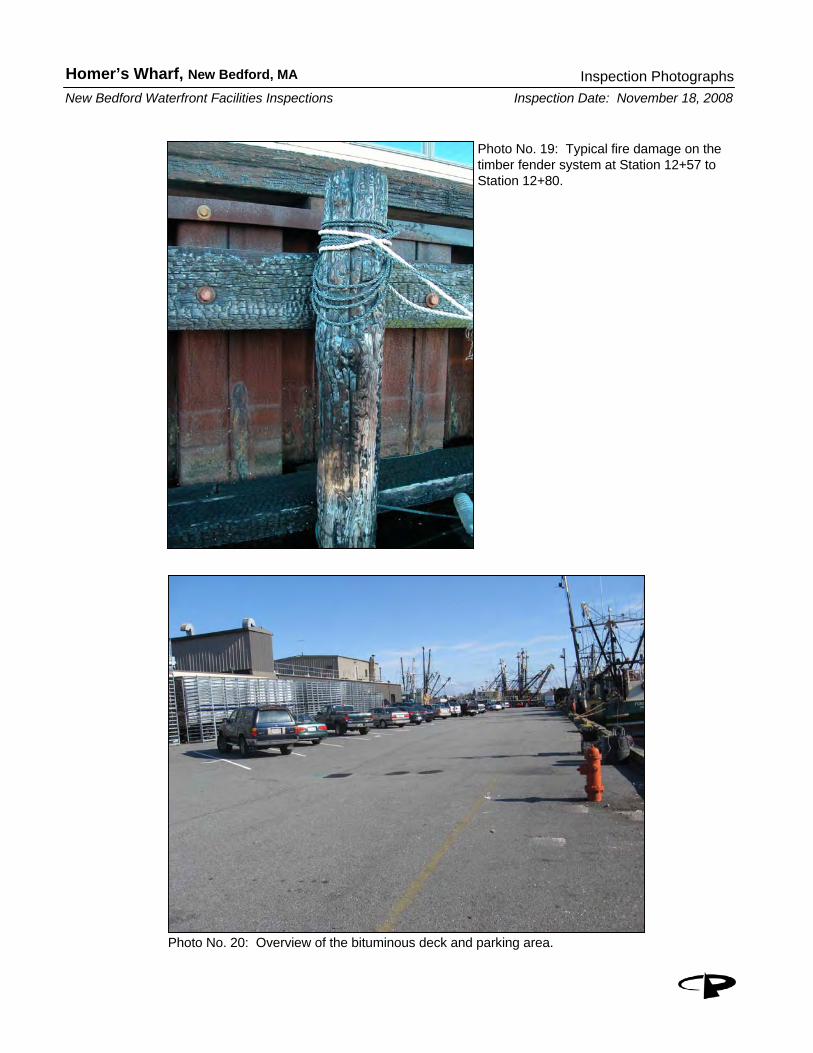
3.3 Fender System From Station 0+00 to Station 5+91, the timber wale and UHMW rub rails were observed to be in overall good condition. From Station 2+55 to Station 3+20, minor damage was observed along the timber wale and UHMW rub rail. The wale was observed to be displaced at Station 3+00, and only held on by the UHMW from Station 3+10 to Station 3+18. The timber wale and UHMW rub rail were observed to be in good condition from Station 3+00 to Station 5+13 with no major deficiencies noted. The timber wale was observed to be damaged and broken, with the UHMW rub rail missing from the face from Station 5+13 to Station 5+45 and from Station 5+86 to Station 5+91 at the corner of the bulkhead. The rubber tire fenders were observed to be in overall good condition. From Station 5+91 to the end of the new fender system at Station 11+70, the timber wale and UHMW rub rails were observed to be in overall fair condition. The rubber tire fenders were observed to be in overall good condition. Typical deficiencies include loose or missing UHMW rub rail and significant damage to the wale in several areas, as shown in Photograph No. 9, 11, and 14 in Appendix A: Photographs. Specific locations of damaged wales, loose rub rails, and missing rub rails are listed in Appendix E – Field Notes. The older fender system protects the steel sheetpile bulkhead from Station 11+70 to Station 13+07. It is comprised of 12-inch diameter timber fender piles at approximately 10 feet on center with 12 inches by 12 inches top and bottom timber wales. The fender piles in this fender system are in overall fair condition with some signs of rot and wearing on faces. The top and bottom wales were observed to be in overall poor condition. They were predominantly hollow due to rot as shown in Photo No. 16 in Appendix A: Photographs. Fire damage was observed on the piles and the wales from Station 12+57 to Station 12+80 (Photo 19). A timber gangway was attached to the bulkhead with rope at Station 12+37. The gangway led to 2 floating docks and was observed to be in poor condition. 3.4 Bituminous Pavement Several areas of local subsidence were observed behind the bulkhead. From Station 2+32 to Station 2+40, a 16-inch wide by 5-inch deep area of subsidence was observed (Photo 5). It appeared as if a hole has been cut through the top of the sheetpile wall at this location for unknown reasons, allowing draining water to remove fill material. At Station 2+95, a 12-inch long by 12-inch wide by 3-inch deep area of subsidence was observed. At Station 7+57, a 48-inch long by 12-inch wide by 1.5-inch deep area of subsidence was observed behind the bulkhead. A 24-inch long by 8-inch wide by 1.5-inch deep area of subsidence was observed at Station 12+12. From Station 11+88 to Station 13+07, a series of small areas of subsidence were observed at approximately 2 feet on center, as shown in Photo No. 17 in Appendix A: Photographs.

Homer’s Wharf
Pare Corporation 5
3.5 Appurtenances Galvanized steel ladders are located around the bulkhead to provide access to and from the deck to the water below. Overall the ladders were observed to be in fair condition. Some of the ladders are in good condition above mean high water, while others have been damaged during impact with vessels causing damage to the rungs and buckling of members. All of the ladders are corroded below mean high water rendering them useless during times of low water. Life rings were observed along the bulkhead at several locations, attached with a 4” x 4” post notched into the timber curb. 4.0 – Structural Condition Assessment 4.1 General Based on the observations obtained from the site inspections, the following provides our assessment of the various structures and components. Existing structural condition determinations were based on visual and tactile observations only, and were limited to accessible and visible portions of the structures. 4.2 Condition Assessment Based upon the visual inspection of topside and underwater structures along with the observed thickness readings, Homer’s Wharf is in generally fair to good condition. Areas of concern include typical damages limited to the timber wale, missing or loose UHMW rub rails, damaged access ladders, and locations of subsidence along the deck. Corrosion along the flanges of the steel sheetpile bulkhead sections was minimal, with greater loss of section in the web areas. The following table represents the thickness readings and estimated remaining section steel sheetpile.
Table 3.2 – Remaining Steel Sheetpile Thickness Nominal Flange Thickness = 0.500” Nominal Web Thickness = 0.375”
Inner Flange Percent Remaining Web Percent Remaining
Outer Flange Percent Remaining
0.465 93.0 0.365 97.3 0.485 97.0 0.485 97.0 0.240 64.0 0.485 97.0 0.455 91.0 0.300 80.0 0.365 73.0 0.435 87.0 0.230 61.3 0.455 91.0 0.455 91.0 0.305 81.3 0.325 65.0 0.455 91.0 0.330 88.0 0.450 90.0 0.460 92.0 0.300 80.0 0.460 92.0 0.445 89.0 0.390 104.0 0.440 88.0 0.530 106.0 0.370 98.7 0.525 105.0 0.505 101.0 0.350 93.3 0.505 101.0 0.535 107.0 0.335 89.3 -- -- 0.490 98.0 0.345 92.0 0.525 105.0 0.505 101.0 0.355 94.7 0.495 99.0

Homer’s Wharf
Pare Corporation 6
0.475 95.0 0.305 81.3 0.470 94.0 0.490 98.0 0.320 85.3 0.460 92.0 0.460 92.0 0.355 94.7 0.530 106.0 0.515 103.0 0.320 85.3 0.435 97.0 0.495 99.0
Typical UT readings on both the web and flanges displayed reduced thicknesses at mean low water. The readings on the flanges were typically higher and near the nominal thickness, showing minimal corrosion and section loss. Thickness readings on the web indicated average section loss of 13.5% with a maximum reading of 38.7% loss. Average section loss on the flanges was 2.6% with a maximum reading of 35.0% section loss on the outer flange at Station 2+00 at mean low water. The section losses observed are such that they do not warrant a reduction in the original allowable loading of 500 pounds per square foot. Further deterioration and loss of section may require reinforcement or rehabilitation to achieve the allowable loading. The installation of cathodic protection can inhibit this loss of section due to corrosion, extending the life of the structure. SECTION 5 RECOMMENDATIONS AND OPINION OF PROBABLE COST 5.1 – Recommendations - General Based on conditions observed during the inspections, and the corresponding assessments of the existing structures, the following recommendations are provided for the repair and rehabilitation of these structures. Opinions of probable cost were generated based upon current industry unit prices for similar work. Breakdowns of cost are provided in the Appendix. The cost opinions provided are for construction only and do not include allowances for engineering, permitting, or construction administration. A 20 percent contingency has been included with these costs. The opinions shown herein are based on a limited investigation and are provided for general information only. This should not be considered an engineer’s estimate, as final design has not been performed, and actual construction costs may be somewhat less or considerably more than indicated, due to fluctuations in the market. The following repairs and remedial measures should be implemented to maintain the integrity of the structure. If deferred these maintenance items could develop into larger deficiencies that are more costly to address. 5.2 – High Priority The following items are considered to have a High Priority, as they affect the usability and safety of the structure:

Homer’s Wharf
Pare Corporation 7
Remove and replace damaged and worn timber wale. Failure to repair damaged areas may lead to additional damage to the fender system and structural damage to the pier. The opinion of probable construction cost for this work is approximately $63,000.
Replace the corroded and damaged access ladders. By nature, the ladders are subject to damage from vessels and require frequent maintenance. Due to the highly corrosive nature of seawater, it is recommenced that the existing steel ladders be replaced with treated timber ladders. The opinion of probable construction cost for this work is approximately $30,000.
Repair areas of subsidence along the wharf. Repairs are to include patching of the steel sheetpile bulkhead (where applicable) to minimize future subsidence, and backfilling and regrading of existing subsidence. The opinion of probable construction cost for this work is approximately $45,000.
5.3 – Lower Priority The following items are considered to have a Lower Priority, as they presently do not affect the usability and safety of the structure, but will need to be addressed in approximately 5 to 10 years.
Install cathodic protection along the length of the steel sheetpile bulkhead. Sacrificial zinc or aluminum anodes minimize corrosion of the steel sheet piling and wale fastening bolts, and will extend the useful life of the sheeting. The opinion of probable construction cost for this work is approximately $343,000.

Figures Homer’s Wharf
New Bedford, Massachusetts

FIGURE 1
LOCUS PLAN
HOMER’S WHARFNEW BEDFORD, MASSACHUSETTS
NEW BEDFORD HARBOR DEVELOPMENT COMMISSIONNEW BEDFORD WATERFRONT FACILITY INSPECTIONS
NOVEMBER 2008
PROJECT LOCATION


Appendix A Photographs
Homer’s Wharf New Bedford, Massachusetts

Homer’s Wharf, New Bedford, MA
Inspection Date: November 18, 2008Inspection Photographs
New Bedford Waterfront Facilities Inspections
Photo No. 1: Overview of Homer’s Wharf from Station 0+00 looking east.
Photo No. 2: Overview of the sheetpile bulkhead and rubber tire fender system from Station 1+50 to Station 2+00.

Homer’s Wharf, New Bedford, MA
Inspection Date: November 18, 2008Inspection Photographs
New Bedford Waterfront Facilities Inspections
Photo No. 3: Typical rubber tire fender with steel brackets along the steel sheetpile bulkhead.
Photo No. 4: Typical condition of the sheetpile bulkhead.

Homer’s Wharf, New Bedford, MA
Inspection Date: November 18, 2008Inspection Photographs
New Bedford Waterfront Facilities Inspections
Photo No. 5: Subsidence behind the sheetpile bulkhead at Station 2+35 to Station 2+40.
Photo No. 6: Bituminous deck with timber curb looking east.

Homer’s Wharf, New Bedford, MA
Inspection Date: November 18, 2008Inspection Photographs
New Bedford Waterfront Facilities Inspections
Photo No. 7: Timber wale with missing UHMW rub rail. Note the damage to the wale.
Photo No. 8: Fire damage on the timber curb at the corner of the bulkhead at Station 5+91.

Homer’s Wharf, New Bedford, MA
Inspection Date: November 18, 2008Inspection Photographs
New Bedford Waterfront Facilities Inspections
Photo No. 9: Docked vessel against the timber wale from Station 5+91 looking south.
Photo No. 10: Hole in steel sheet pile bulkhead at Station 5+93.

Homer’s Wharf, New Bedford, MA
Inspection Date: November 18, 2008Inspection Photographs
New Bedford Waterfront Facilities Inspections
Photo No. 11: Loose UHMW rub rail near Station 6+90.
Photo No. 12: Overview of the timber curb and bituminous deck from Station 7+50 looking west.

Homer’s Wharf, New Bedford, MA
Inspection Date: November 18, 2008Inspection Photographs
New Bedford Waterfront Facilities Inspections
Photo No. 13: Subsidence behind the sheetpile bulkhead at Station 7+57.
Photo No. 14: Typical loose UHMW rub rail near Station 7+75.

Homer’s Wharf, New Bedford, MA
Inspection Date: November 18, 2008Inspection Photographs
New Bedford Waterfront Facilities Inspections
Photo No. 15: Old timber fender system starting at Station 11+70.
Photo No. 16: End of rotted top wale of the old timber fender system.

Homer’s Wharf, New Bedford, MA
Inspection Date: November 18, 2008Inspection Photographs
New Bedford Waterfront Facilities Inspections
Photo No. 17: Timber curb and bituminous deck. Note several small areas of subsidence.
Photo No. 18: Timber gangway at Station 12+37.
Homer’s Wharf, New Bedford, MA
Inspection Date: November 18, 2008Inspection Photographs
New Bedford Waterfront Facilities Inspections
Photo No. 19: Typical fire damage on the timber fender system at Station 12+57 to Station 12+80.
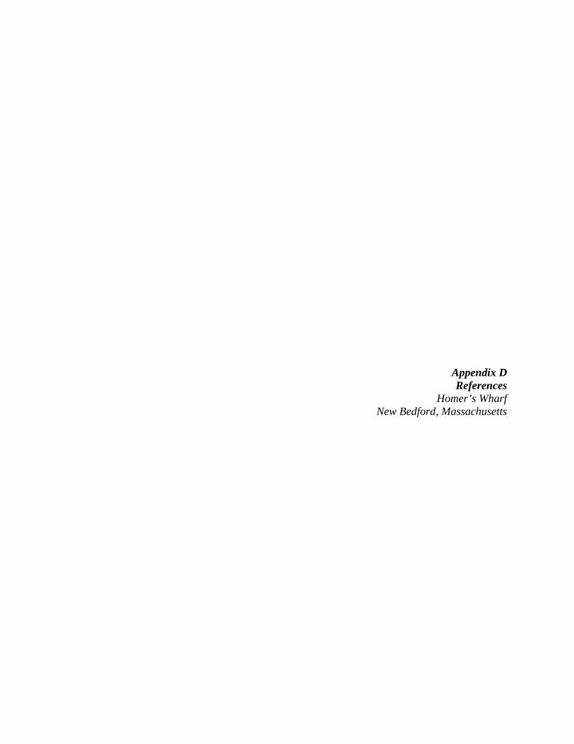
Photo No. 20: Overview of the bituminous deck and parking area.

Homer’s Wharf, New Bedford, MA
Inspection Date: November 18, 2008Inspection Photographs
New Bedford Waterfront Facilities Inspections
Photo No. 21: Typical steel face plate mounted to steel sheetpile. (Photo by Childs Engineering Corp.)
Photo No. 22: Typical underwater hardware. (Photo by Childs Engineering Corp.)

Homer’s Wharf, New Bedford, MA
Inspection Date: November 18, 2008Inspection Photographs
New Bedford Waterfront Facilities Inspections
Photo No. 23: Typical underwater bolt connected to internal wale. (Photo by Childs Engineering Corp.)
Photo No. 24: Typical underwater fender and connection. (Photo by Childs Engineering Corp.)

Appendix B Key Personnel
Homer’s Wharf New Bedford, Massachusetts

Homer’s Wharf
Pare Corporation
KEY PERSONNEL
The following personnel were involved with this project including but not limited to the topside and underwater inspections and the preparation of this report: Name Employer Responsibilities Karl Hammond, P.E. PARE Corporation Project Manager, Lead Engineer Ernest O. Rabideau, Jr., P.E. PARE Corporation Project Reviewer Matt Bellisle, P.E. PARE Corporation Principal in Charge Craig Sams, P.E. Childs Engineering Corporation Principal in Charge Robert Garrity, P.E. Childs Engineering Corporation Project Engineer for Underwater Inspections Kevin Champagne, P.E. PARE Corporation Support Engineer Richard Fitzgerald, P.E. Childs Engineering Corporation Underwater Inspection Team Charlie Marshall Roberts Childs Engineering Corporation Underwater Inspection Team Robert Welch Childs Engineering Corporation Underwater Inspection Team Phil Iantosca Childs Engineering Corporation Underwater Inspection Team Nicholas B. Sarata Childs Engineering Corporation Underwater Inspection Team Ryan McCoy PARE Corporation Topside Inspection Briscoe B. Lang PARE Corporation Permitting Services

Appendix C Backup Data for Cost Estimates
Homer’s Wharf New Bedford, Massachusetts

HOMER'S WHARFOPINION OF PROBABLE CONSTRUCTION COST
February, 2009
QTY UNIT UNIT PRICE TOTALHigh Priority Repairs
1. Mobilization/Demobilization 1 LS 25,000.00$ 25,000.00$ 2. Demolition and Removal 1 LS 25,000.00$ 25,000.00$ 3. Replace Timber Wale 4 MBF 6,500.00$ 22,750.00$ 4. Replace Access Ladders 11 EACH 2,000.00$ 22,000.00$ 5. Repair Areas of Subsidence 1 LS 20,000.00$ 20,000.00$
Subtotal 114,750.00$ Contingency 20% 22,950.00$ Total 137,700.00$
Low Priority Repairs
1. Mobilization/Demobilization 1 LS 30,000.00$ 30,000.00$ 3. Install Cathodic Protection 21,325 LB 12.00$ 255,900.00$
Subtotal 285,900.00$ Contingency 20% 57,180.00$ Total 343,080.00$
WHARF REHABILITATION
PARE Project No.: 08216.00
Appendix D References
Homer’s Wharf New Bedford, Massachusetts

Homer’s Wharf
Pare Corporation
REFERENCES
The following references were utilized during the preparation of this report and the development of the recommendations presented herein: 1. “About the Port – Key Locations”, New Bedford Harbor Development Commission,
http://www.newbedford-ma.gov/PortofNewBedford/AboutPort/KeyLocations.html 2. “Maritime History of Massachusetts – Merrill’s Wharf Historic District”, National Park
Service, http://www.nps.gov/history/NR/travel/maritime/mer.htm. 3. Construction Drawings “Proposed Repairs and Improvements to Wharves and Piers in
New Bedford and Fairhaven, MA”, Tibbetts Engineering Corp., January 23, 1998 (Revised March 20, 1998).
4. Construction Drawings “South Terminal Urban Renewal Project”, Goodkind and
O’Dea, Inc., March 1974. 5. ASCE Underwater Investigations: Standard Practice Manual (2001).

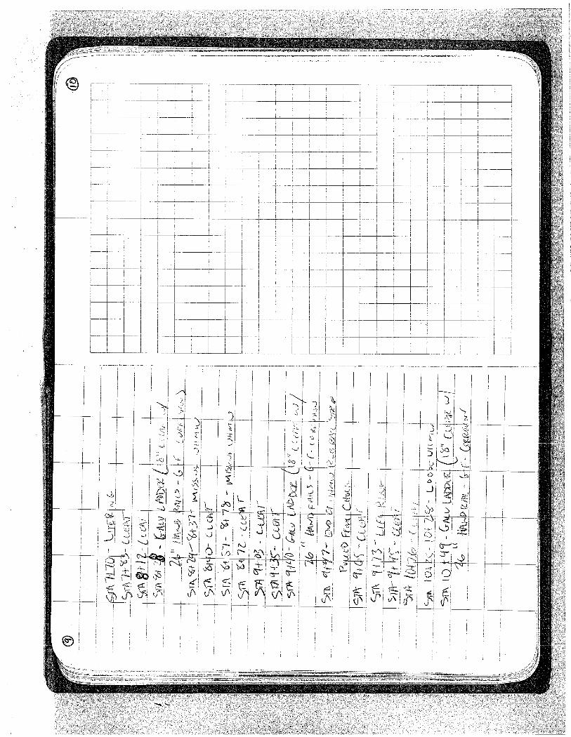
Appendix E Field Notes
Homer’s Wharf New Bedford, Massachusetts