Embed Size (px)
Citation preview
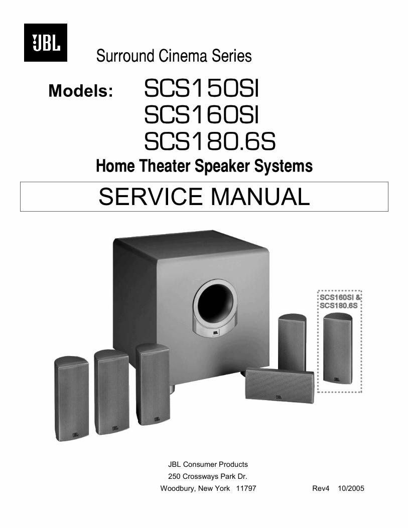
Surround Cinema Series
Models: SCS150SI SCS160SI SCS180.6S
Home Theater Speaker Systems
SERVICE MANUAL
JBL Consumer Products 250 Crossways Park Dr. Woodbury, New York 11797 Rev4 10/2005
- CONTENTS -
BASIC SPECIFICATIONS……………….……….……………….1
DETAILED SPECIFICATIONS ……..………………..…………..2
CONNECTIONS…………… …..……………...…………..……...3
OPERATION………………………………………………………. 6
BASIC TROUBLESHOOTING……..……….…………………….7
EXPLODED VIEW……..……….………………………………….8
TEST SET-UP AND PROCEDURE……..……….………..……..9
PCB DRAWINGS…………… ……..………………..…….……..10
MECHANICAL/SATELLITE PARTS LIST………………………16
ELECTRICAL PARTS LIST ……………....……………….…….17
IC/TRANSISTOR PINOUTS……..…….…………………..…….22
SCHEMATICS …………………………………………..…….23
PACKING..………….………………………………..…………….26 SCS150SI/SCS160SI/SCS180.6S Systems Frequency Response 30Hz – 20kHz (–6dB)
Satellites Recommended Power 10 – 100 watts Impedance 8 ohms nominal Sensitivity 88dB @ 1 watt/1 meter Tweeter One 1/2" (13mm) titanium laminate dome, video-shielded Midrange Dual 3" (75mm) drivers, video-shielded Dimensions (H x W x D) 8-1/8" x 3-1/2" x 3-7/8" (206mm x 89mm x 99mm) Weight 2.65lb/1.2kg
Center Recommended Power 10 – 100 watts Impedance 8 ohms nominal Sensitivity 88dB @ 1 watt/1 meter Tweeter One 1/2" (13mm) titanium laminate dome, video-shielded Midrange Dual 3" (75mm) drivers, video-shielded Dimensions (H x W x D) 3-1/2" x 8-1/8" x 3-7/8" (89mm x 206mm x 99mm) Weight 2.65lb/1.2kg
Subwoofer Amplifier 150 watts RMS Woofer 10" (254mm) woofer, bass-reflex enclosure Dimensions (H x W x D) 17-3/4" x 15-3/4" x 16-3/4" (451mm x 400mm x 426mm) Weight 35 lb/15.9kg
Occasional refinements may be made to existing products without notice but will always meet or exceed original specifications unless otherwise stated
SCS150SI/SCS160SI/SCS180.6S
1

150W Powered Sub/ Plate Amp
LINE VOLTAGE Yes/No Hi/Lo Line Unit NotesUS 120vac/60Hz Yes 108-132 Vrms Normal Operation
Asia 100vac/50Hz Yes 90-110 Vrms Normal Operation
Parameter Specification Unit QA Test Limits Conditions NotesAmp SectionType (Class AB, D, other) D D n/aLoad Impedance (speaker) 4 Ohms n/a NominalRated Output Power 150 Watts 145 1 input drivenTHD@ Rated Power 0.08 % 1 22k filterTHD @ 1 Watt 0.1 % 0.5 22k filterDC Offset 10 mV-DC 20 @ Speaker Outputs
Damping factor >100 DF 30Measured at speaker terminals, Output power 140 Watts THD 0.1 %
Input SensitivityInput Frequency 50 Hz 50 Nominal Freq. 1 input drivenLine Input (L&R) 250 mVrms ±2dB To Rated Power 1 input driven
LFE Input 145 mVrms ±2dB To Rated Power LFE input driven onlySpeaker/Hi Level Input 2 Vrms ±2dB To Rated Power (-20 dB below Line In)...1 input driven
Signal to NoiseSNR-A-Weighted 100 dBA 85 rel. to rated power A-Weighting filterSNR-unweighted 90 dBr 80 rel. to rated power 22k filterSNR @ 1W-unweighted 60 dBr 55 rel. to 1W Output 22k filter
Residual Noise Floor 1 mVrms 2Volume @max, using RMS reading DMM/VOM (or A/P)
Residual Noise Floor 1 mVrms(max) 2Volume @max, w/ A/P Swept Bandpass Measurement (Line freq.+ harmonics)
Input ImpedanceLine input L&R , LFE >15 K ohms n/a Nominal
Speaker/Hi Level Input 4.7 K ohms n/a Nominal
FiltersLeft & Right Low Pass fixed Hz -- ±2dB
Slope & Q 4th dB/Octave n/aLFE Low Pass fixed Hz -- ±2dB
Slope & Q 2nd dB/Octave n/aSubsonic filter (HPF) Hz -- ±2dB
Slope & Q 2nd dB/Octave n/a
Limiter YES -- n/a
FeaturesLFE Input YES functional BW Limited to 500 HzVolume pot Taper (lin/log) log -- functional ATO YES functional
Signal Sensing (ATO)
ATO test Frequency 50 Hz functional
ATO Line Level 2 mV functional2mV@50Hz into Line Input w/ 1 ch. driven
ATO Speaker level input 50 mV fucntional50mV@50Hz into Line Input w/ 1 ch. driven
ATO Turn-on time 5 ms functionalAmp connected and AC on, then input signal applied
Auto Mute/ Turn-OFF Time 15 minutes functional T before muting, after signal is removed Auto turn of time (T) must be 10 > T <15
Power on Delay time 3 sec. functional AC Power Applied
Transients/PopsATO Transient 5 mV-peak 10 @ Speaker OutputsTurn-on Transient 50 mV-peak 100 @ Speaker Outputs AC Line cycled from OFF to ONTurn-off Transient 50 mV-peak 100 @ Speaker Outputs AC Line cycled from ON to OFF
Efficiency
Stand-by Input Power 14 Watts 16 @ nom. line voltage
Maximum allowable input power under nominal Input voltage and frequency, HOT or COLD operation.
Power Cons.@rated power 230 Watts 250 @ nom. line voltage 140 Watts @ 4 Ohms nominal line voltage
ProtectionShort Circuit Protection YES -- functional Direct short at output
Thermal Protection 65 deg. C -- functional @1/8 max unclipped Power Temperature rise should not exceed 35K rise
DC Offset Protection YES -- functional DC present at Speaker Out leads Relay or crowbar (for driver/fire protection)Line Fuse Rating
US Version 3.15 Amps Type-T or Slo Blo External fuse with UL/SEMKO rated holder
SCS150SI/SCS160SI/SCS180.6S
2
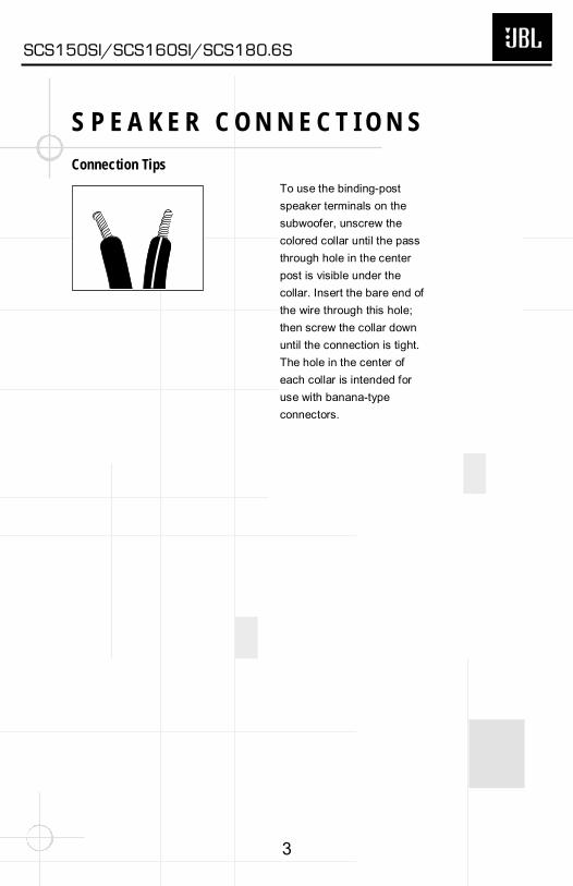
S P E A K E R C O N N E C T I O N SConnection Tips
To use the binding-post
speaker terminals on the
subwoofer, unscrew the
colored collar until the pass
through hole in the center
post is visible under the
collar. Insert the bare end of
the wire through this hole;
then screw the collar down
until the connection is tight.
The hole in the center of
each collar is intended for
use with banana-type
connectors.
SCS150SI/SCS160SI/SCS180.6S
3
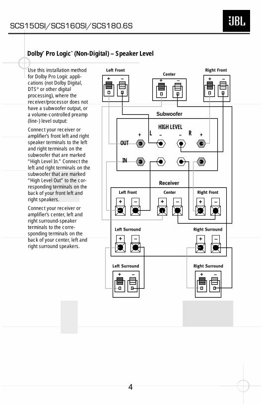
Dolby* Pro Logic* (Non-Digital) – Speaker Level
Use this installation methodfor Dolby Pro Logic appli-cations (not Dolby Digital,DTS® or other digitalprocessing), where thereceiver/processor does nothave a subwoofer output, or a volume-controlled preamp(line-) level output:
Connect your receiver oramplifier’s front left and rightspeaker terminals to the leftand right terminals on thesubwoofer that are marked“High Level In.” Connect theleft and right terminals on thesubwoofer that are marked“High Level Out” to the cor-responding terminals on theback of your front left andright speakers.
Connect your receiver oramplifier’s center, left andright surround-speakerterminals to the corre-sponding terminals on theback of your center, left andright surround speakers.
Right Front
Right Surround
Left Front
Left Surround
Center
+ – + –
+ –
+ –+ – + –
+ –
Left Front Center
+ –
Left Surround
Right Front
+ –
Right Surround
+ –
Subwoofer
Receiver
HIGH LEVEL+ – – +L R
OUT
IN
SCS150SI/SCS160SI/SCS180.6S
4

Dolby Pro Logic (Non-Digital) – Line Level
Use this installation methodfor Dolby Pro Logic appli-cations (not Dolby Digital, DTSor other digital processing),where the receiver/processoris equipped with a subwooferoutput, or a volume-controlledpreamp (line-) level output:
Use RCA-type patch cords to connect the line-levelsubwoofer outputs on yourreceiver or amplifier to theline-level inputs on thesubwoofer. IMPORTANT: Donot use the LFE input on thesubwoofer with Dolby
Pro Logic processors. Note: Ifyour receiver or amplifier onlyhas one subwoofer outputjack, then you will need to usea Y-connector (not included).Plug the male end of the Y-connector into your receiveror amplifier’s subwooferoutput jack, and connect eachof the two female ends toseparate RCA-type patchcords. Finally, plug the RCA-type patch cords into the line-level inputs on the subwoofer.
Connect each speaker to the corresponding speakerterminals on your receiver or amplifier.
Make sure your receiver orprocessor is correctlyconfigured to indicate that thesubwoofer is “On.”
Note for advanced users: Ifyour receiver/processor has abuilt-in low-pass crossoverfilter for the subwoofer output,you may use the LFE input tobypass the subwoofer’sinternal crossover.
Use this installation methodfor Dolby Digital, DTS or otherdigital surround processors:
Use the line-level input jackmarked “LFE” for the Low-Frequency Effects channel.Connect this jack to the LFEoutput or subwoofer output on your receiver or amplifier.Connect each speaker to thecorresponding speaker
terminals on your receiver or amplifier.
Make sure that you haveconfigured your surround-sound processor for“Subwoofer On.” The frontleft, front right, center andrear speakers should all beset to “Small.”
Dolby Digital or DTS (or Other Digital Surround Mode) Connection
LINE LEVEL IN
LFE INPUTLFE OUTL
R
SUBWOOFERRECEIVER
+ –
+ –
+ –
+ –
+ –
+ –+ –
+ –+ –+ –
Receiver
Subwoofer Out
LeftFront
LeftRear
RightFront
RightRear
Subwoofer
R L
R
L
Center
Line-Level
In
Right Surround
Right Front
Left Surround
Left FrontCenter
SCS150SI/SCS160SI/SCS180.6S
5
O P E R A T I O N
MIN MAX
SubwooferLevel
MIN MAX
SubwooferLevel
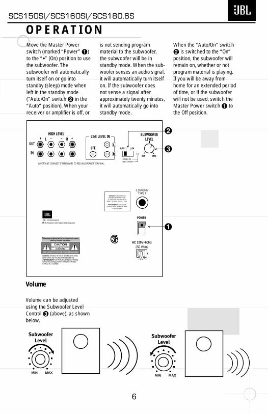
Move the Master Powerswitch (marked “Power” ¡)to the “•” (On) position to usethe subwoofer. The subwoofer will automaticallyturn itself on or go intostandby (sleep) mode whenleft in the standby mode(“Auto/On” switch ™ in the“Auto” position). When yourreceiver or amplifier is off, or
is not sending programmaterial to the subwoofer, the subwoofer will be instandby mode. When the sub-woofer senses an audio signal,it will automatically turn itselfon. If the subwoofer does not sense a signal afterapproximately twenty minutes,it will automatically go intostandby mode.
When the “Auto/On” switch™ is switched to the “On”position, the subwoofer willremain on, whether or notprogram material is playing.If you will be away fromhome for an extended periodof time, or if the subwooferwill not be used, switch theMaster Power switch ¡ tothe Off position.
Volume
POWER
HIGH LEVEL+ – – +
SUBWOOFERLEVEL
OUT
IN
L RLINE LEVEL IN
LFEL
R
AUTO ON
MIN MAX
AC 120V~60Hz250 Watts
3.15A/250VTYPE T
£
¡
™
IMPORTANT: CONNECT STRIPED WIRE TO RED ( ) SPEAKER TERMINAL.
GREEN: ONRED: STANDBY
+
AVIS : RISQUE DE CHOC ÉLECTRIQUE-NE PAS OUVRIR
WARNING: FOR CONTINUEDPROTECTION AGAINST RISK
OF FIRE, REPLACE ONLY WITHSAME TYPE 3.15A, 250 VOLT FUSE
AVERTISSEMENT: UTILISEZ UNFUSIBLE DE RECHANGE DE MEME
TYPE 3.15A, 250V
A Harman International CompanyJBL, Incorporated
This area is designed to become quite warmduring normal operation
CAUTIONRISK OF ELECTRIC SHOCK
DO NOT OPEN
WARNING: TO REDUCE THE RISK OF FIRE OR ELECTRIC SHOCK, DO NOT EXPOSE THIS APPLIANCE TO RAIN OR MOISTURE.AVERTISSEMENT: POUR PRÉVENIR LES RISQUES D'INCENDIE OU DE CHOC ÉLECTRIQUE, ÉVITER D'EXPOSER CET APPAREIL A LA PLUIE OU A L'HUMIDITÉ.
Volume can be adjustedusing the Subwoofer LevelControl £ (above), as shownbelow.
SCS150SI/SCS160SI/SCS180.6S
6
If there is no sound from anyof the speakers:• Check that receiver/amplifieris on and a source is playing.• Check that the powered subwoofer is plugged in, andits Power switch ¡ isswitched on to the “•”position.• Check all wires and con-nections between receiver/amplifier and speakers. Makesure all wires are connected.Make sure none of thespeaker wires are frayed, cut or punctured.• Review proper operation ofyour receiver/amplifier.
If there is no sound comingfrom one speaker:• Check the “Balance” controlon your receiver/amplifier.• Check all wires and con-nections between receiver/amplifier and speakers. Makesure all wires are connected.Make sure none of the speaker wires are frayed, cut or punctured.• In Dolby Digital or DTSmodes, make sure that thereceiver/processor isconfigured so that the speakerin question is enabled.• Turn off all electronics andswitch the speaker in questionwith one of the other speakers
that is working correctly. Turneverything back on, anddetermine whether theproblem is in the same place,i.e., the speaker that wasworking previously now hasno sound and the speaker thatwas not working now soundsfine; or whether it has moved,i.e., the speaker that was notworking still has no sound andthe speaker that was workingis still fine. If the problem is inthe same place, the source ofthe problem is most likely withyour receiver or amplifier, andyou should consult the owner’smanual for that product forfurther information. If theproblem has followed thespeaker, consult your dealerfor further assistance or, ifthat is not possible, visit ourWeb site at www.jbl.com forfurther information.
If there is no sound from thecenter speaker:• Check all wires andconnections betweenreceiver/amplifier andspeaker. Make sure all wiresare connected. Make surenone of the speaker wires arefrayed, cut or punctured.• If your receiver/processor isset in Dolby Pro Logic mode,make sure the center speaker
is not in phantom mode.• If your receiver/processor is set in Dolby Digital or DTSmode, make sure thereceiver/processor is con-figured so that the centerspeaker is enabled.
If the system plays at lowvolumes but shuts off asvolume is increased:• Check all wires and con-nections between receiver/amplifier and speakers. Makesure all wires are connected.Make sure none of the speaker wires are frayed, cutor punctured.• If more than one pair of mainspeakers is being used, checkthe minimum impedancerequirements of yourreceiver/amplifier.
If there is low (or no) bassoutput:• Make sure the connectionsto the left and right “SpeakerInputs” have the correct polarity (+ and –).• Make sure the subwoofer is plugged into an activeelectrical outlet.• Make sure the poweredsubwoofer is plugged in, andits Power switch ¡ isswitched on to the “•”position.
T R O U B L E S H O O T I N G
• In Dolby Digital or DTSmodes, make sure yourreceiver/processor isconfigured so that thesubwoofer and LFE outputare enabled.
SCS150SI/SCS160SI/SCS180.6S
7
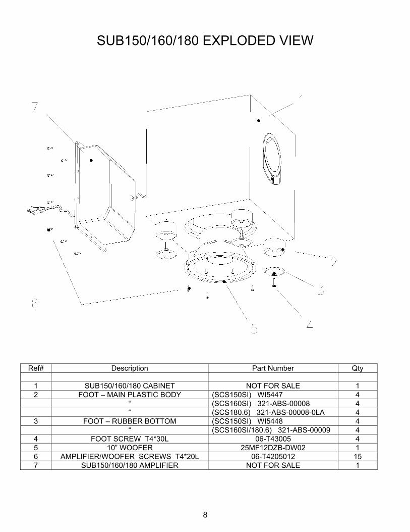
SUB150/160/180 EXPLODED VIEW
Ref# Description Part Number Qty
1 SUB150/160/180 CABINET NOT FOR SALE 1 2 FOOT – MAIN PLASTIC BODY (SCS150SI) WI5447 4 “ (SCS160SI) 321-ABS-00008 4 “ (SCS180.6) 321-ABS-00008-0LA 4
3 FOOT – RUBBER BOTTOM (SCS150SI) WI5448 4 “ (SCS160SI/180.6) 321-ABS-00009 4
4 FOOT SCREW T4*30L 06-T43005 4 5 10” WOOFER 25MF12DZB-DW02 1 6 AMPLIFIER/WOOFER SCREWS T4*20L 06-T4205012 15 7 SUB150/160/180 AMPLIFIER NOT FOR SALE 1
8

Test Set Up and Procedure
Equipment needed: • Function/signal generator/sweep generator • Integrated Amplifier • Multimeter • Speaker cables General Unit Function (UUT = Unit Under Test) 1) From the signal generator, connect one line level (RCA) cable to the Subwoofer Line Level Input jacks L/R
on the UUT. Use a Y-cable from a mono source if necessary to connect to both inputs. Do not connect to the single LFE input.
2) Turn on generator; adjust to 100mV, 50 Hz. 3) Plug in UUT; turn the power switch ON. LED should switch from Red to Green. Turn LEVEL control full
clockwise (MAX) 4) LED should Green; immediate and vigorous bass response should be heard and felt from port tube
opening. 5) Turn off generator, turn LEVEL control full counterclockwise (MIN), and disconnect RCA cable. 6) Connect one pair of speaker cables to Speaker Level input terminal (IN) on UUT. Cables should be
connected to an integrated amplifier fed by the signal generator. 7) Turn on generator and adjust so that speaker level input at the amplifier is 2.0V, 50 Hz. Turn LEVEL control
full clockwise. 8) Green LED should light; immediate and vigorous bass response should be heard and felt from the port
tube opening. Sweep Function 1) Follow steps 6-8 above, using a sweep generator as a signal source. 2) Sweep generator from 20Hz to 300Hz. Listen to the cabinet and drivers for any rattles, clicks, buzzes or
any other noises. If any unusual noises are heard, remove woofers and test. Driver Function 1) Remove woofer from cabinet (instructions on exploded view drawing); detach + and - wire clips. 2) Check DC resistance of woofer; it should be 3.4 ohms ±10% 3) Connect a pair of speaker cables to driver terminals. Cables should be connected to an integrated amplifier
fed by a signal generator. Turn on generator and adjust so that speaker level output is 5.0V. 4) Sweep generator from 20Hz to 1kHz. Listen to driver for any rubbing, buzzing, or other unusual noises.
SCS150SI/SCS160SI/SCS180.6S
9
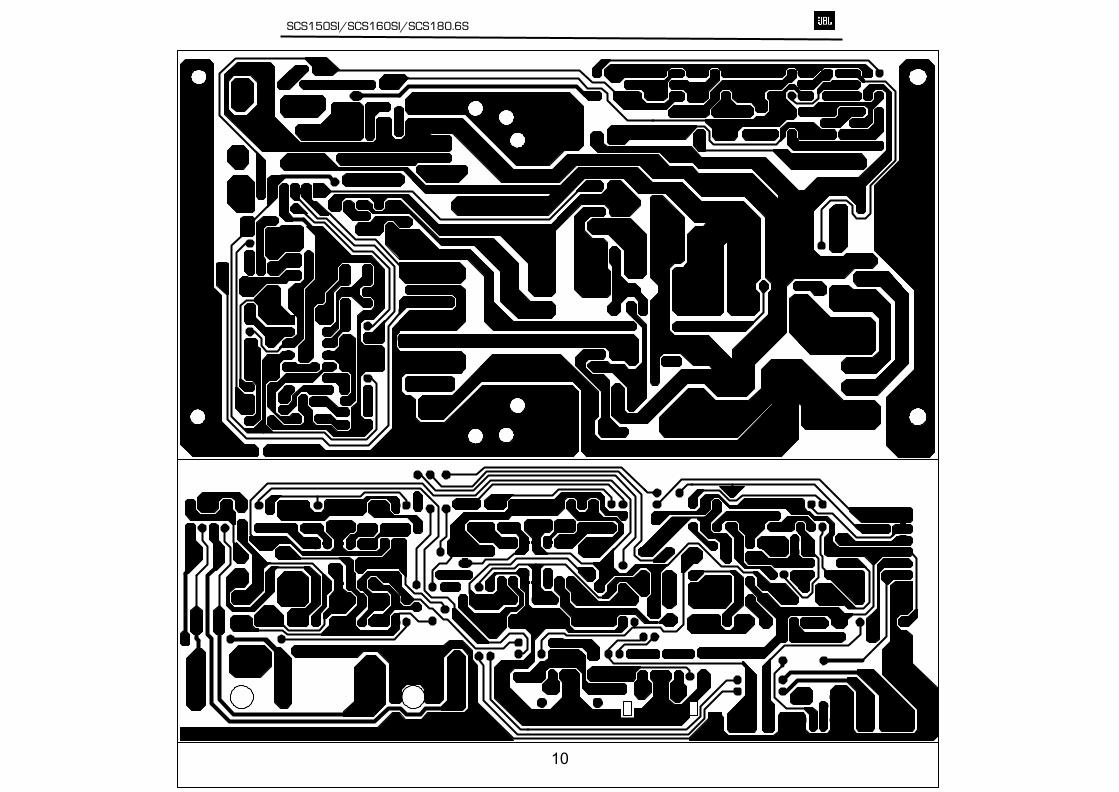
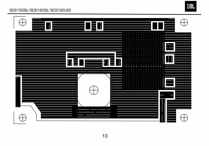
SCS150SI/SCS160SI/SCS180.6S
10
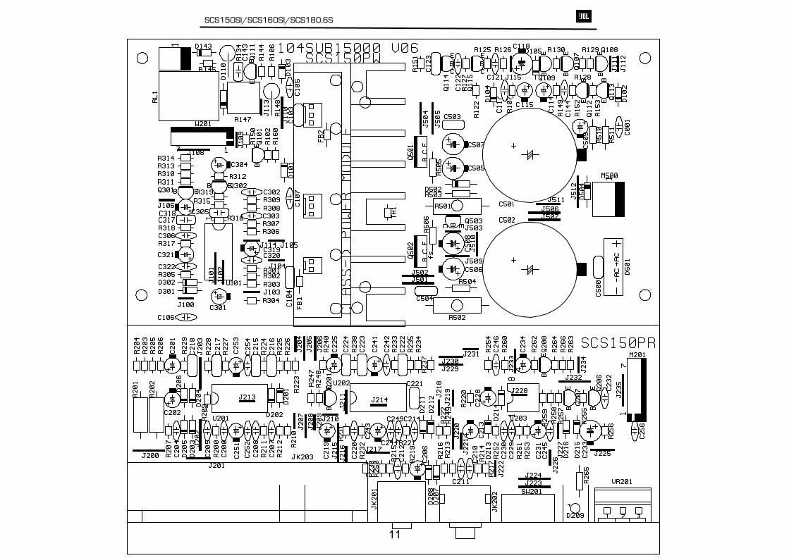
SCS150SI/SCS160SI/SCS180.6S
11
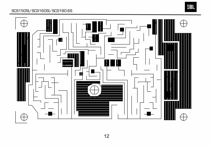
SCS150SI/SCS160SI/SCS180.6S
12
SCS150SI/SCS160SI/SCS180.6S
13
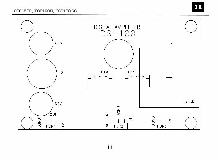
SCS150SI/SCS160SI/SCS180.6S
14
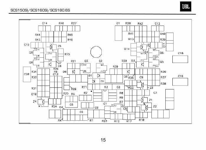
SCS150SI/SCS160SI/SCS180.6S
15
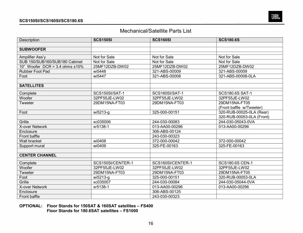
SCS150SI/SCS160SI/SCS180.6S Mechanical/Satellite Parts List
Description SCS150SI SCS160SI SCS180.6S SUBWOOFER
Amplifier Ass’y Not for Sale Not for Sale Not for Sale SUB 150/SUB160/SUB180 Cabinet Not for Sale Not for Sale Not for Sale 10” Woofer DCR = 3.4 ohms ±10% 25MF12DZB-DW02 25MF12DZB-DW02 25MF12DZB-DW02 Rubber Foot Pad wi5448 321-ABS-00009 321-ABS-00009 Foot wi5447 321-ABS-00008 321-ABS-00008-0LA SATELLITES
Complete SCS150SI/SAT-1 SCS160SI/SAT-1 SCS180.6S SAT-1 Woofer 32PF55JE-LW02 32PF55JE-LW02 32PF55JE-LW02 Tweeter 29DM15NA-FT03 29DM15NA-FT03 29DM15NA-FT05
(Front baffle w/Tweeter) Foot wi5213-g 325-000-00151
320-RUB-00025-0LA (Rear) 320-RUB-00053-0LA (Front)
Grille xc035006 244-030-00083 244-030-05043-0VA X-over Network xr5138-1 013-AA00-00296 013-AA00-00296 Enclosure 306-ABS-00124 Front baffle 243-030-00323 Wall bracket wi0408 372-000-00042 372-000-00042 Support mural wi0409 325-FE-00163 325-FE-00163 CENTER CHANNEL
Complete SCS150SI/CENTER-1 SCS160SI/CENTER-1 SCS180.6S CEN-1 Woofer 32PF55JE-LW02 32PF55JE-LW02 32PF55JE-LW02 Tweeter 29DM15NA-FT03 29DM15NA-FT03 29DM15NA-FT05 Foot wi5213-g 325-000-00151 320-RUB-00053-0LA Grille xc035007 244-030-00084 244-030-05044-0VA X-over Network xr5138-1 013-AA00-00296 013-AA00-00296 Enclosure 306-ABS-00125 Front baffle 243-030-00323 OPTIONAL: Floor Stands for 150SAT & 160SAT satellites – FS400
Floor Stands for 180.6SAT satellites – FS1000
16
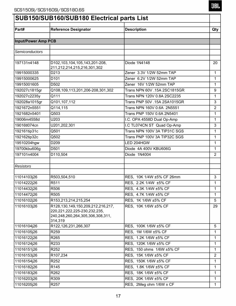
SUB150/SUB160/SUB180 Electrical parts List Part# Reference Designator Description Qty
Input/Power Amp PCB
Semiconductors
197131n4148 D102,103,104,105,143,201-208, 211,212,214,215,216,301,302
Diode 1N4148 20
19915000335 D213 Zener 3.3V 1/2W 52mm TAP 119915000625 D101 Zener 6.2V 1/2W 52mm TAP 119915001605 D502 Zener 16V 1/2W 52mm TAP 1192027c1815gr Q108,109,113,201,206-208,301,302 Trans NPN 60V .15A 2SC1815GR 9192027c2235y Q111 Trans NPN 120V 0.8A 2SC2235 1192028a1015gr Q101,107,112 Trans PNP 50V .15A 2SA1015GR 31921672n5551 Q114,115 Trans NPN 160V 0.6A 2N5551 21921682n5401 Q503 Trans PNP 150V 0.6A 2N5401 119006m4558d U203 I.C. OPA 4558D Dual Op-Amp 119016tl074cn U201,202,301 I.C TL074CN ST Quad Op-Amp 3192161tip31c Q501 Trans NPN 100V 3A TIP31C SGS 1192162tip32c Q502 Trans PNP 100V 3A TIP32C SGS 119510204hgw D209 LED 204HGW 119700kbu606g D501 Diode 4A 400V KBU606G 1197101n4004 D110,504 Diode 1N4004 2
Resistors
11014103j26 R503,504,510 RES, 10K 1/4W ±5% CF 26mm 311014222j26 R511 RES, 2.2K 1/4W ±5% CF 111014432j26 R506 RES, 4.3K 1/4W ±5% CF 111014472j26 R505 RES, 4.7K 1/4W ±5% CF 111016102j26 R153,213,214,215,254 RES, 1K 1/6W ±5% CF 511016103j26 R128,130,149,150,209,212,216,217,
220,221,222,225-230,232,235, 240,248,260,264,305,306,308,311, 314,319
RES, 10K 1/6W ±5% CF 29
11016104j26 R122,126,231,266,307 RES, 100K 1/6W ±5% CF 511016105j26 R259 RES, 1M 1/6W ±5% CF 111016122j26 R265 RES, 1.2K 1/6W ±5% CF 111016124j26 R233 RES, 120K 1/6W ±5% CF 111016151j26 R252 RES, 150 ohms 1/6W ±5% CF 111016153j26 R107,234 RES, 15K 1/6W ±5% CF 211016154j26 R252 RES, 150K 1/6W ±5% CF 111016182j26 R145 RES, 1.8K 1/6W ±5% CF 111016183j26 R262 RES, 18K 1/6W ±5% CF 111016203j26 R309 RES, 20K 1/6W ±5% CF 111016205j26 R257 RES, 2Meg ohm 1/6W ± CF 1
SCS150SI/SCS160SI/SCS180.6S
17
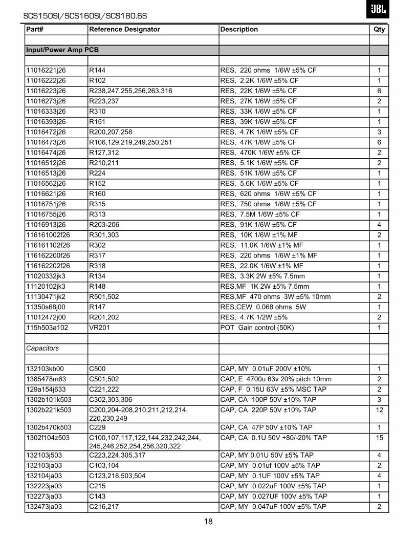
Part# Reference Designator Description Qty
Input/Power Amp PCB
11016221j26 R144 RES, 220 ohms 1/6W ±5% CF 111016222j26 R102 RES, 2.2K 1/6W ±5% CF 111016223j26 R238,247,255,256,263,316 RES, 22K 1/6W ±5% CF 611016273j26 R223,237 RES, 27K 1/6W ±5% CF 211016333j26 R310 RES, 33K 1/6W ±5% CF 111016393j26 R151 RES, 39K 1/6W ±5% CF 111016472j26 R200,207,258 RES, 4.7K 1/6W ±5% CF 311016473j26 R106,129,219,249,250,251 RES, 47K 1/6W ±5% CF 611016474j26 R127,312 RES, 470K 1/6W ±5% CF 211016512j26 R210,211 RES, 5.1K 1/6W ±5% CF 211016513j26 R224 RES, 51K 1/6W ±5% CF 111016562j26 R152 RES, 5.6K 1/6W ±5% CF 111016621j26 R160 RES, 620 ohms 1/6W ±5% CF 111016751j26 R315 RES, 750 ohms 1/6W ±5% CF 111016755j26 R313 RES, 7.5M 1/6W ±5% CF 111016913j26 R203-206 RES, 91K 1/6W ±5% CF 4116161002f26 R301,303 RES, 10K 1/6W ±1% MF 2116161102f26 R302 RES, 11.0K 1/6W ±1% MF 1116162200f26 R317 RES, 220 ohms 1/6W ±1% MF 1116162202f26 R318 RES, 22.0K 1/6W ±1% MF 111020332jk3 R134 RES, 3.3K 2W ±5% 7.5mm 111120102jk3 R148 RES,MF 1K 2W ±5% 7.5mm 111130471jk2 R501,502 RES,MF 470 ohms 3W ±5% 10mm 211350s68j00 R147 RES,CEW 0.068 ohms 5W 111012472j00 R201,202 RES, 4.7K 1/2W ±5% 2115h503a102 VR201 POT Gain control (50K) 1
Capacitors
132103kb00 C500 CAP, MY 0.01uF 200V ±10% 11385478m63 C501,502 CAP, E 4700u 63v 20% pitch 10mm 2129a154j633 C221,222 CAP, F 0.15U 63V ±5% MSC TAP 21302b101k503 C302,303,306 CAP, CA 100P 50V ±10% TAP 31302b221k503 C200,204-208,210,211,212,214,
220,230,249CAP, CA 220P 50V ±10% TAP 12
1302b470k503 C229 CAP, CA 47P 50V ±10% TAP 11302f104z503 C100,107,117,122,144,232,242,244,
245,246,252,254,256,320,322CAP, CA 0.1U 50V +80/-20% TAP 15
132103j503 C223,224,305,317 CAP, MY 0.01U 50V ±5% TAP 4132103ja03 C103,104 CAP, MY 0.01uf 100V ±5% TAP 2132104ja03 C123,218,503,504 CAP, MY 0.1UF 100V ±5% TAP 4132223ja03 C215 CAP, MY 0.022uF 100V ±5% TAP 1132273ja03 C143 CAP, MY 0.027UF 100V ±5% TAP 1132473ja03 C216,217 CAP, MY 0.047uF 100V ±5% TAP 2
SCS150SI/SCS160SI/SCS180.6S
18
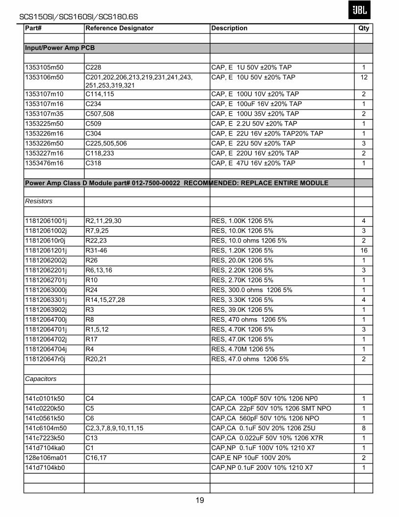
Part# Reference Designator Description Qty
Input/Power Amp PCB
1353105m50 C228 CAP, E 1U 50V ±20% TAP 11353106m50 C201,202,206,213,219,231,241,243,
251,253,319,321CAP, E 10U 50V ±20% TAP 12
1353107m10 C114,115 CAP, E 100U 10V ±20% TAP 21353107m16 C234 CAP, E 100uF 16V ±20% TAP 11353107m35 C507,508 CAP, E 100U 35V ±20% TAP 21353225m50 C509 CAP, E 2.2U 50V ±20% TAP 11353226m16 C304 CAP, E 22U 16V ±20% TAP20% TAP 11353226m50 C225,505,506 CAP, E 22U 50V ±20% TAP 31353227m16 C118,233 CAP, E 220U 16V ±20% TAP 21353476m16 C318 CAP, E 47U 16V ±20% TAP 1
Power Amp Class D Module part# 012-7500-00022 RECOMMENDED: REPLACE ENTIRE MODULE
Resistors
11812061001j R2,11,29,30 RES, 1.00K 1206 5% 411812061002j R7,9,25 RES, 10.0K 1206 5% 3118120610r0j R22,23 RES, 10.0 ohms 1206 5% 211812061201j R31-46 RES, 1.20K 1206 5% 1611812062002j R26 RES, 20.0K 1206 5% 111812062201j R6,13,16 RES, 2.20K 1206 5% 311812062701j R10 RES, 2.70K 1206 5% 111812063000j R24 RES, 300.0 ohms 1206 5% 111812063301j R14,15,27,28 RES, 3.30K 1206 5% 411812063902j R3 RES, 39.0K 1206 5% 111812064700j R8 RES, 470 ohms 1206 5% 111812064701j R1,5,12 RES, 4.70K 1206 5% 311812064702j R17 RES, 47.0K 1206 5% 111812064704j R4 RES, 4.70M 1206 5% 1118120647r0j R20,21 RES, 47.0 ohms 1206 5% 2
Capacitors
141c0101k50 C4 CAP,CA 100pF 50V 10% 1206 NP0 1141c0220k50 C5 CAP,CA 22pF 50V 10% 1206 SMT NPO 1141c0561k50 C6 CAP,CA 560pF 50V 10% 1206 NPO 1141c6104m50 C2,3,7,8,9,10,11,15 CAP,CA 0.1uF 50V 20% 1206 Z5U 8141c7223k50 C13 CAP,CA 0.022uF 50V 10% 1206 X7R 1141d7104ka0 C1 CAP,NP 0.1uF 100V 10% 1210 X7 1128e106ma01 C16,17 CAP,E NP 10uF 100V 20% 2141d7104kb0 CAP,NP 0.1uF 200V 10% 1210 X7 1
SCS150SI/SCS160SI/SCS180.6S
19
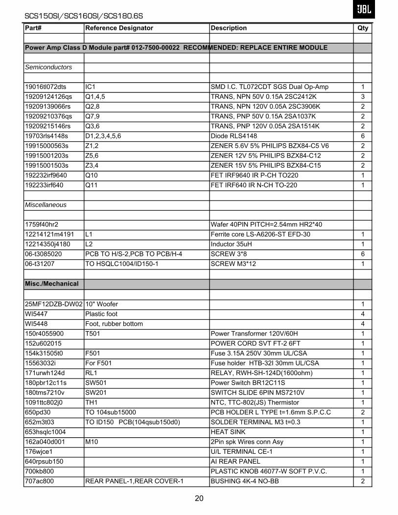
Part# Reference Designator Description Qty
Power Amp Class D Module part# 012-7500-00022 RECOMMENDED: REPLACE ENTIRE MODULE
Semiconductors
19016tl072dts IC1 SMD I.C. TL072CDT SGS Dual Op-Amp 119209124126qs Q1,4,5 TRANS, NPN 50V 0.15A 2SC2412K 319209139066rs Q2,8 TRANS, NPN 120V 0.05A 2SC3906K 219209210376qs Q7,9 TRANS, PNP 50V 0.15A 2SA1037K 219209215146rs Q3,6 TRANS, PNP 120V 0.05A 2SA1514K 219703rls4148s D1,2,3,4,5,6 Diode RLS4148 619915000563s Z1,2 ZENER 5.6V 5% PHILIPS BZX84-C5 V6 219915001203s Z5,6 ZENER 12V 5% PHILIPS BZX84-C12 219915001503s Z3,4 ZENER 15V 5% PHILIPS BZX84-C15 2192232irf9640 Q10 FET IRF9640 IR P-CH TO220 1192233irf640 Q11 FET IRF640 IR N-CH TO-220 1
Miscellaneous
1759f40hr2 Wafer 40PIN PITCH=2.54mm HR2*4012214121m4191 L1 Ferrite core LS-A6206-ST EFD-30 112214350j4180 L2 Inductor 35uH 106-t3085020 PCB TO H/S-2,PCB TO PCB/H-4 SCREW 3*8 606-t31207 TO HSQLC1004/ID150-1 SCREW M3*12 1
Misc./Mechanical
25MF12DZB-DW02 10" Woofer 1WI5447 Plastic foot 4WI5448 Foot, rubber bottom 4150r4055900 T501 Power Transformer 120V/60H 1152u602015 POWER CORD SVT FT-2 6FT 1154k31505t0 F501 Fuse 3.15A 250V 30mm UL/CSA 115563032i For F501 Fuse holder HTB-32I 30mm UL/CSA 1171urwh124d RL1 RELAY, RWH-SH-124D(1600ohm) 1180pbr12c11s SW501 Power Switch BR12C11S 1180tms7210v SW201 SWITCH SLIDE 6PIN MS7210V 11091ttc802j0 TH1 NTC, TTC-802(JS) Thermistor 1650pd30 TO 104sub15000 PCB HOLDER L TYPE t=1.6mm S.P.C.C 2652m3t03 TO ID150�PCB(104qsub150d0) SOLDER TERMINAL M3 t=0.3 1653hsqlc1004 HEAT SINK 1162a040d001 M10 2Pin spk Wires conn Asy 1176wjce1 U/L TERMINAL CE-1 1640rpsub150 AI REAR PANEL 1700kb800 PLASTIC KNOB 46077-W SOFT P.V.C. 1707ac800 REAR PANEL-1,REAR COVER-1 BUSHING 4K-4 NO-BB 2
SCS150SI/SCS160SI/SCS180.6S
20
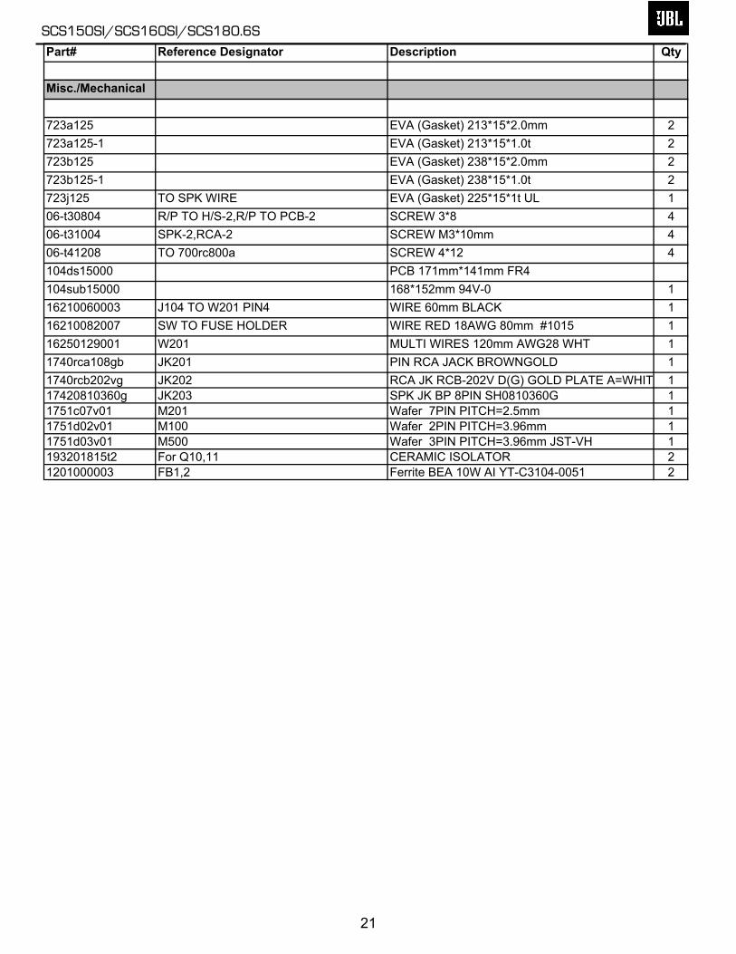
Part# Reference Designator Description Qty
Misc./Mechanical
723a125 EVA (Gasket) 213*15*2.0mm 2723a125-1 EVA (Gasket) 213*15*1.0t 2723b125 EVA (Gasket) 238*15*2.0mm 2723b125-1 EVA (Gasket) 238*15*1.0t 2723j125 TO SPK WIRE EVA (Gasket) 225*15*1t UL 106-t30804 R/P TO H/S-2,R/P TO PCB-2 SCREW 3*8 406-t31004 SPK-2,RCA-2 SCREW M3*10mm 406-t41208 TO 700rc800a SCREW 4*12 4104ds15000 PCB 171mm*141mm FR4104sub15000 168*152mm 94V-0 116210060003 J104 TO W201 PIN4 WIRE 60mm BLACK 116210082007 SW TO FUSE HOLDER WIRE RED 18AWG 80mm #1015 116250129001 W201 MULTI WIRES 120mm AWG28 WHT 11740rca108gb JK201 PIN RCA JACK BROWNGOLD 11740rcb202vg JK202 RCA JK RCB-202V D(G) GOLD PLATE A=WHIT 117420810360g JK203 SPK JK BP 8PIN SH0810360G 11751c07v01 M201 Wafer 7PIN PITCH=2.5mm 11751d02v01 M100 Wafer 2PIN PITCH=3.96mm 11751d03v01 M500 Wafer 3PIN PITCH=3.96mm JST-VH 1193201815t2 For Q10,11 CERAMIC ISOLATOR 21201000003 FB1,2 Ferrite BEA 10W AI YT-C3104-0051 2
SCS150SI/SCS160SI/SCS180.6S
21
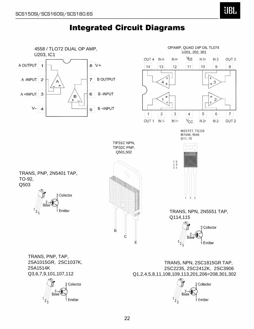
Integrated Circuit Diagrams
C
B
E
TIP31C NPN, TIP32C PNP,
Q501,502
4558 / TLO72 DUAL OP AMP,U203, IC1
OPAMP, QUAD 14P DIL TL074U201, 202, 301
TRANS, PNP, 2N5401 TAP,TO-92,Q503
TRANS, PNP, TAP,2SA1015GR, 2SC1037K, 2SA1514KQ3,6,7,9,101,107,112
TRANS, NPN, 2N5551 TAP,Q114,115
TRANS, NPN, 2SC1815GR TAP,2SC2235, 2SC2412K, 2SC3906
Q1,2,4,5,8,11,108,109,113,201,206=208,301,302
1 2 3
MOSFET, TO220 IRF640, 9640Q11, 10
1. G2. D3. S
SCS150SI/SCS160SI/SCS180.6S
22
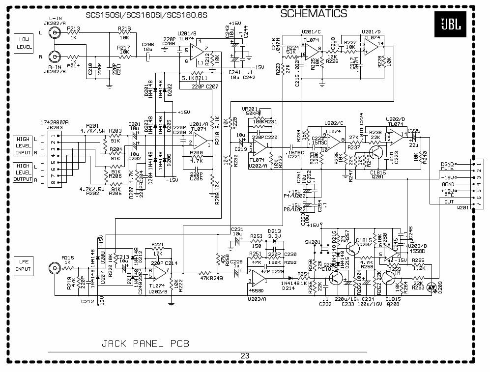
SCHEMATICSSCS150SI/SCS160SI/SCS180.6S
23
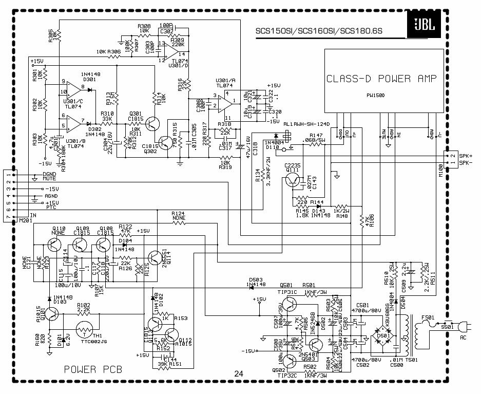
SCS150SI/SCS160SI/SCS180.6S
24
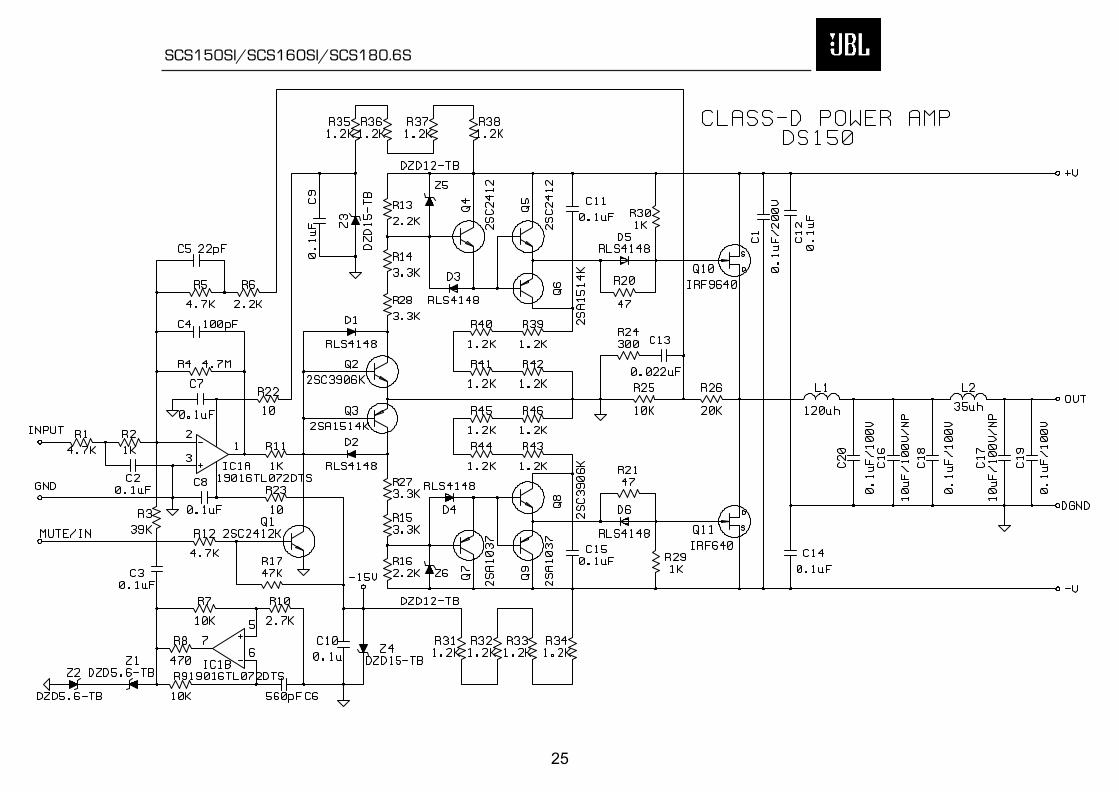
SCS150SI/SCS160SI/SCS180.6S
25
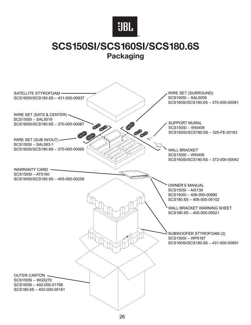
SATELLITE STYROFOAMSCS160SI/SCS180.6S – 431-000-00937
WIRE SET (SURROUND)SCS150SI – SAL5009SCS160SI/SCS180.6S – 370-000-00081
OWNER’S MANUALSCS150SI – AI5139SCS160SI – 406-000-00890SCS180.6S – 406-000-05102
WARRANTY CARDSCS150SI – AT5160SCS160SI/SCS180.6S – 405-000-00258
WALL BRACKETSCS150SI – WI0408SCS160SI/SCS180.6S – 372-000-00042
SUPPORT MURALSCS150SI – WI0409SCS160SI/SCS180.6S – 325-FE-00163
OUTER CARTONSCS150SI – WG5270SCS160SI – 402-000-01768SCS180.6S – 402-000-05181
SUBWOOFER STYROFOAM (2)SCS150SI – WP5187SCS160SI/SCS180.6S – 431-000-00691
WIRE SET (SATS & CENTER)SCS150SI – SAL5019SCS160SI/SCS180.6S – 370-000-00087
WIRE SET (SUB IN/OUT)SCS150SI – SAL063-1SCS160SI/SCS180.6S – 370-000-00069
WALL BRACKET WARNING SHEETSCS180.6S – 405-000-05021
SCS150SI/SCS160SI/SCS180.6SPackaging
26


![Home Theater Speaker Systems SERVICE MANUAL - …users.atw.hu/bazsielektron/Hang Box/JBL SCS180[1].6... · amplifier’s center, left and right surround-speaker ... IMPORTANT: Do](https://img.dokumen.tips/doc/110x75/5aee33a87f8b9aa17b8c016d/home-theater-speaker-systems-service-manual-usersatwhubazsielektronhang.jpg)