Embed Size (px)
Citation preview

SAG582127100 System Application Guide
Spec. No. 582127100 (Model 722NBBB) Issue AB, October 2, 2014
Page 1 of 28
This document is property of Emerson Network Power, Energy Systems, North America, Inc. and contains confidential and proprietary information owned by Emerson Network Power, Energy Systems, North America, Inc. Any copying, use, or disclosure of it without the written permission of Emerson Network Power, Energy Systems, North America, Inc. is strictly prohibited.
SYSTEM OVERVIEW Description: -48V DC @ up to 2000 Amperes Bulk Output Power System
The NetSure™ 722NBBB Bulk Output Power System is intended for use to expand or replace legacy -48V DC rectifiers while retaining the distribution power board. It can be used with any -48V DC power system, regardless of vendor or plant type. The 722NBBB is an integrated power system containing rectifiers, intelligent control, metering, and monitoring. This power system is designed to power a load while charging a positive grounded battery. This power system is capable of operating in a batteryless installation or off battery for maintenance purposes. The power system is designed for operation with the positive output grounded. This system consists of the following components. • Main Rectifier Module Mounting Shelf
The system contains a main rectifier module mounting shelf. This shelf houses up to five (5) rectifier modules, the controller, a controller interface board, and a system interface board. Refer to Power Data Sheet PD588705000 for more information. ACU+ (Advanced Control Unit Plus) Controller: The controller provides power system control (including low voltage battery disconnect (LVBD) and low voltage load disconnect (LVLD) control), rectifier control (including a charge control function), metering functions, monitoring functions, and local/remote alarm functions. The controller also supports rectifier temperature compensation if the system is equipped with a temperature probe(s). Temperature probe(s) may be designated to monitor ambient temperature and/or battery temperature. The controller also provides data acquisition, system alarm management, and advanced battery and energy management. The controller contains an LCD display and keypad for local access. The controller provides Ethernet connection and supports software upgrade via its USB port. It also comes with a comprehensive web page and SNMP capability for remote system management. Refer to the ACU+ Controller Instructions (UM1M820BNA) for more information.
• Expansion Rectifier Module Mounting Shelf The system contains one or more expansion rectifier module mounting shelves, each of which houses up to six (6) rectifier modules. Refer to Power Data Sheet PD588705000 for more information.
• Rectifier Modules The system contains rectifier modules, which provide load power, battery float current, and battery recharge current during normal operating conditions. Refer to the Rectifier Instructions (UM1R483500E) for more information.
Home

SAG582127100 System Application Guide Issue AB, October 2, 2014 Spec. No. 582127100 (Model 722NBBB)
Page 2 of 28
This document is property of Emerson Network Power, Energy Systems, North America, Inc. and contains confidential and proprietary information owned by Emerson Network Power, Energy Systems, North America, Inc. Any copying, use, or disclosure of it without the written permission of Emerson Network Power, Energy Systems, North America, Inc. is strictly prohibited.
General Specifications See detailed specifications starting on page 24.
Family: NetSure™ System Spec. No.: 582127100 System Model: 722NBBB System AC Input Voltage AC input is connected to the individual rectifier shelf(s). See
PD588705000 for ratings. System DC Output Voltage -48V DC, nominal System Output Capacity: 2000A, maximum 588705000 Shelf Ratings: See PD588705000. 1R483500E Rectifier Rating: See UM1R483500E. System Agency Approval: UL 60950 Recognized; CAN/CSA 22.2, No. 60950-00,
NEBS (pending) Framework Type: Relay Rack Mounted Mounting Width: 23 Inches, nominal Mounting Depth:
588705000 Rectifier Mounting Shelf: 18.75 Inches
Access: Front for Operation Front and Rear for Installation and Maintenance
Control: Microprocessor Color: Module Faceplates: Textured Gray
Module Mounting Shelf and Module Bodies: Bright Zinc Plating Environment: -40°C to +65°C (-40°F to +149°F)
Home

System Application Guide SAG582127100 Spec. No. 582127100 (Model 722NBBB) Issue AB, October 2, 2014
Page 3 of 28
This document is property of Emerson Network Power, Energy Systems, North America, Inc. and contains confidential and proprietary information owned by Emerson Network Power, Energy Systems, North America, Inc. Any copying, use, or disclosure of it without the written permission of Emerson Network Power, Energy Systems, North America, Inc. is strictly prohibited.
TABLE OF CONTENTS
SYSTEM OVERVIEW................................................................................................................................................. 1
MAIN COMPONENTS ILLUSTRATIONS .................................................................................................................. 5 582127100 ............................................................................................................................................................. 5
LIST DESCRIPTIONS ................................................................................................................................................ 6 List Numbers ........................................................................................................................................................ 6
List 1: Common Equipment (Relay Rack or Rail Mounted System) ............................................................... 6 List 2: Common Equipment (Ship Loose System) .......................................................................................... 6 List 10: Main Rectifier Module Mounting Shelf Interface Components ........................................................... 6 List 11: Expansion Rectifier Module Mounting Shelf Interface Components .................................................. 7 List 20: Main Rectifier Module Mounting Shelf to Expansion Rectifier Module Mounting Shelf Interface Components ...................................................................................................................................... 7 List 21: Expansion Rectifier Module Mounting Shelf to Expansion Rectifier Module Mounting Shelf Interface Components ...................................................................................................................................... 8
ACCESSORY DESCRIPTIONS ................................................................................................................................. 9 ACU+ (Advanced Control Unit Plus) Controller, P/N 1M820DNA ................................................................... 9 Optional Temperature Probes ............................................................................................................................ 9 In-Line Fuse and Resistor Pigtail Kits ............................................................................................................. 11
1A In-Line Fuse Pigtail Kit, P/N 431300200 ................................................................................................... 11 1A In-Line Fuse Pigtail Kit, P/N 431300300 ................................................................................................... 11 1A In-Line Fuse Pigtail Kit, P/N 535135 ......................................................................................................... 11 49.9 Ohm In-Line Resistor Pigtail Kit, P/N 424227900 .................................................................................. 11 49.9 Ohm In-Line Resistor Pigtail Kit, P/N 424228000 .................................................................................. 11 49.9 Ohm In-Line Resistor Pigtail Kit, P/N 424228100 .................................................................................. 11
Optional SM-Temp Temperature Concentrator, P/N 547490 ......................................................................... 12 Rectifiers ............................................................................................................................................................ 12
Rectifier Module, P/N 1R483500E ................................................................................................................. 12 Rectifier Module Mounting Position Blank Cover Panel, P/N 21140440 ...................................................... 12 Relay Racks and Shipping Brackets ............................................................................................................... 13 Transition Plates to Mount Relay Rack on Top of GNB Absolyte IIP Batteries .......................................... 14 Standard Crimp Lugs and Lug Hardware Kits ............................................................................................... 15
Standard Crimp Lug Tables ........................................................................................................................... 15 3/8-16 Lug Hardware Kit, P/N 556277 ........................................................................................................... 15
Customer Cables ............................................................................................................................................... 16 CAN Bus Input Cable, P/N 556430 ................................................................................................................ 16 CAN Bus Output Cable, P/N 556238 ............................................................................................................. 16
Replacement Assemblies ................................................................................................................................. 16
RECOMMENDED WIRE SIZES, BRANCH CIRCUIT PROTECTION, CRIMP LUGS, AND WIRING ILLUSTRATIONS ..................................................................................................................................................... 17
Relay Rack Frame Grounding Requirements ................................................................................................. 17 AC Input Branch Circuit Protection and Wire Size Selection ....................................................................... 17 External Alarm, Reference, Monitoring, and Control Connections .............................................................. 17 DC Output Connections .................................................................................................................................... 22
SPECIFICATIONS .................................................................................................................................................... 24 1. System ........................................................................................................................................................... 24
1.1 Environmental Ratings ............................................................................................................................. 24 1.2 Compliance Information ........................................................................................................................... 24 1.3 System Interface Board Ratings .............................................................................................................. 25 1.4 IB2 (ACU+ Interface Board) Ratings ....................................................................................................... 25
2. Module Mounting Assembly ........................................................................................................................ 25 3. Rectifier .......................................................................................................................................................... 25 4. Controller ....................................................................................................................................................... 25

SAG582127100 System Application Guide Issue AB, October 2, 2014 Spec. No. 582127100 (Model 722NBBB)
Page 4 of 28
This document is property of Emerson Network Power, Energy Systems, North America, Inc. and contains confidential and proprietary information owned by Emerson Network Power, Energy Systems, North America, Inc. Any copying, use, or disclosure of it without the written permission of Emerson Network Power, Energy Systems, North America, Inc. is strictly prohibited.
MECHANICAL SPECIFICATIONS .......................................................................................................................... 26 Overall Dimensions ........................................................................................................................................... 26 Weights ............................................................................................................................................................... 26
RELATED DOCUMENTATION ................................................................................................................................ 27

System Application Guide SAG582127100 Spec. No. 582127100 (Model 722NBBB) Issue AB, October 2, 2014
Page 5 of 28
This document is property of Emerson Network Power, Energy Systems, North America, Inc. and contains confidential and proprietary information owned by Emerson Network Power, Energy Systems, North America, Inc. Any copying, use, or disclosure of it without the written permission of Emerson Network Power, Energy Systems, North America, Inc. is strictly prohibited.
MAIN COMPONENTS ILLUSTRATIONS 582127100
COMMON EQUIPMENT List 1: Relay Rack or Rail Mounted System List 2: Ship Loose System
Rectifier Module: 1R483500E (see UM1R483500E)
ACU+ Controller (Main Rectifier Module Mounting Shelf): 1M820DNA
Main Rectifier Module Mounting Shelf: 58870500061, 58870500062, or 58870500063 (see PD588705000)
List 10: Main Rectifier Module Mounting Shelf Interface Components (Provides DC output lug landing busbar assemblies for the main rectifier module mounting shelf.) List 11: Expansion Rectifier Module Mounting Shelf Interface Components (Provides DC output lug landing busbar assemblies for an expansion rectifier module mounting shelf and busbar interconnecting links.) List 20: Main Rectifier Module Mounting Shelf to Expansion Rectifier Module Mounting Shelf Interface Components (Provides mounting angles and DC output lug landing busbar assemblies which span between a main rectifier module mounting shelf and an expansion rectifier module mounting shelf.) List 21: Expansion Rectifier Module Mounting Shelf to Expansion Rectifier Module Mounting Shelf Interface Components (Provides mounting angles and DC output lug landing busbar assemblies which span between an expansion rectifier module mounting shelf and another expansion rectifier module mounting shelf and busbar interconnecting links.)
Expansion Rectifier Module Mounting Shelf(s): 58870500051, 58870500052, or 58870500053 (see PD588705000)
System Interface Board and Controller Interface Board (behind panel)
Home
SAG582127100 System Application Guide Issue AB, October 2, 2014 Spec. No. 582127100 (Model 722NBBB)
Page 6 of 28
This document is property of Emerson Network Power, Energy Systems, North America, Inc. and contains confidential and proprietary information owned by Emerson Network Power, Energy Systems, North America, Inc. Any copying, use, or disclosure of it without the written permission of Emerson Network Power, Energy Systems, North America, Inc. is strictly prohibited.
LIST DESCRIPTIONS List Numbers List 1: Common Equipment (Relay Rack or Rail Mounted System)
Features ♦ Provides common equipment for one “bulk output” bay rated for up to 2000 amperes mounted in a relay
rack or on shipping brackets. Ordering Notes 1) Order a relay rack or shipping brackets per “Relay Racks and Shipping Brackets” on page 13. If required,
order relay rack transition plates per “Transition Plates to Mount Relay Rack on Top of GNB Absolyte IIP Batteries” on page 14.
2) Order interface components for the main rectifier module mounting shelf as required per List 10 or interface components for the main rectifier module mounting shelf and one (1) expansion rectifier module mounting shelf per List 20.
3) Order interface components for one (1) to four (4) expansion rectifier module mounting shelf(s) as required per List 11 or interface components for an expansion rectifier module mounting shelf to an expansion rectifier module mounting shelf per List 21. In systems using List 20 and List 21 interface components, if a fourth expansion rectifier module mounting shelf is required, also order a List 11 for the fourth expansion rectifier module mounting shelf.
List 2: Common Equipment (Ship Loose System)
Features ♦ Provides common equipment for one “bulk output” bay rated for up to 2000 amperes to be mounted in a
customer rack. Ordering Notes 1) Order interface components for the main rectifier module mounting shelf per List 10. 2) Order interface components for one (1) to four (4) expansion rectifier module mounting shelf(s) as
required per List 11.
List 10: Main Rectifier Module Mounting Shelf Interface Components Features ♦ Provides DC output lug landing busbar assemblies for the main rectifier module mounting shelf. Provides
shelf rack mounting hardware. The main rectifier module mounting shelf must be ordered separately. Refer to Power Data Sheet PD588705000.
♦ The main rectifier module mounting shelf provides a mounting slot for the ACU+ controller. Also provided in the main rectifier module mounting shelf is the system interface board which provides customer connections for two (2) external battery fuse alarm inputs, four (4) external load fuse alarm inputs, one (1) load shunt input, one (1) battery shunt input, one (1) LVD driver output, one (1) LVD sense input, and RS-485 port. Two temperature inputs are provided directly to the internal system interface board. Also provided in the main rectifier module mounting shelf is the IB2 ACU+ interface board which provides eight (8) programmable form-C relay outputs, eight (8) programmable binary inputs, and two (2) temperature inputs.
Ordering Notes 1) For a shipped loose system, order one (1) List 10 per system. 2) Order the main rectifier module mounting shelf per PD588705000 (choices are 58870500061,
558870500062, or 58870500063). 3) Order up to five (5) rectifier modules for the main rectifier module mounting shelf, P/N 1R483500E. 4) Order a rectifier module mounting position blank cover panel, P/N 21140440, for each empty rectifier
module mounting position in the system, as desired.
Home
System Application Guide SAG582127100 Spec. No. 582127100 (Model 722NBBB) Issue AB, October 2, 2014
Page 7 of 28
This document is property of Emerson Network Power, Energy Systems, North America, Inc. and contains confidential and proprietary information owned by Emerson Network Power, Energy Systems, North America, Inc. Any copying, use, or disclosure of it without the written permission of Emerson Network Power, Energy Systems, North America, Inc. is strictly prohibited.
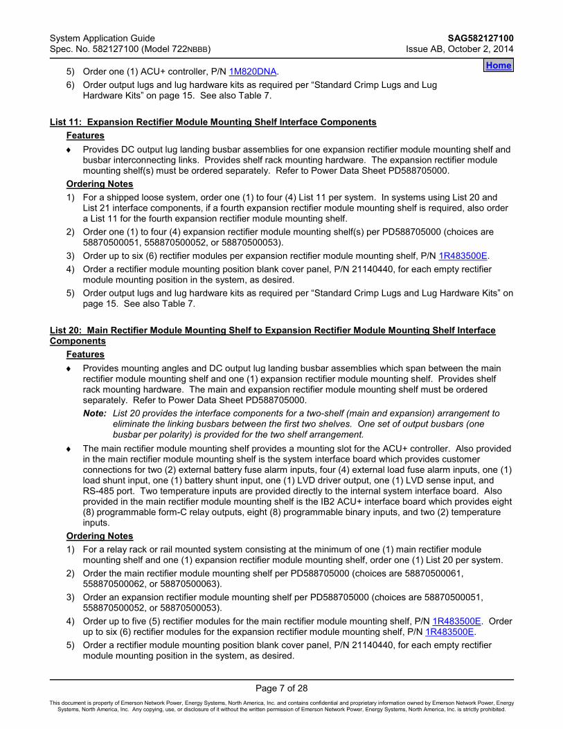
5) Order one (1) ACU+ controller, P/N 1M820DNA. 6) Order output lugs and lug hardware kits as required per “Standard Crimp Lugs and Lug
Hardware Kits” on page 15. See also Table 7.
List 11: Expansion Rectifier Module Mounting Shelf Interface Components Features ♦ Provides DC output lug landing busbar assemblies for one expansion rectifier module mounting shelf and
busbar interconnecting links. Provides shelf rack mounting hardware. The expansion rectifier module mounting shelf(s) must be ordered separately. Refer to Power Data Sheet PD588705000.
Ordering Notes 1) For a shipped loose system, order one (1) to four (4) List 11 per system. In systems using List 20 and
List 21 interface components, if a fourth expansion rectifier module mounting shelf is required, also order a List 11 for the fourth expansion rectifier module mounting shelf.
2) Order one (1) to four (4) expansion rectifier module mounting shelf(s) per PD588705000 (choices are 58870500051, 558870500052, or 58870500053).
3) Order up to six (6) rectifier modules per expansion rectifier module mounting shelf, P/N 1R483500E. 4) Order a rectifier module mounting position blank cover panel, P/N 21140440, for each empty rectifier
module mounting position in the system, as desired. 5) Order output lugs and lug hardware kits as required per “Standard Crimp Lugs and Lug Hardware Kits” on
page 15. See also Table 7.
List 20: Main Rectifier Module Mounting Shelf to Expansion Rectifier Module Mounting Shelf Interface Components
Features ♦ Provides mounting angles and DC output lug landing busbar assemblies which span between the main
rectifier module mounting shelf and one (1) expansion rectifier module mounting shelf. Provides shelf rack mounting hardware. The main and expansion rectifier module mounting shelf must be ordered separately. Refer to Power Data Sheet PD588705000. Note: List 20 provides the interface components for a two-shelf (main and expansion) arrangement to
eliminate the linking busbars between the first two shelves. One set of output busbars (one busbar per polarity) is provided for the two shelf arrangement.
♦ The main rectifier module mounting shelf provides a mounting slot for the ACU+ controller. Also provided in the main rectifier module mounting shelf is the system interface board which provides customer connections for two (2) external battery fuse alarm inputs, four (4) external load fuse alarm inputs, one (1) load shunt input, one (1) battery shunt input, one (1) LVD driver output, one (1) LVD sense input, and RS-485 port. Two temperature inputs are provided directly to the internal system interface board. Also provided in the main rectifier module mounting shelf is the IB2 ACU+ interface board which provides eight (8) programmable form-C relay outputs, eight (8) programmable binary inputs, and two (2) temperature inputs.
Ordering Notes 1) For a relay rack or rail mounted system consisting at the minimum of one (1) main rectifier module
mounting shelf and one (1) expansion rectifier module mounting shelf, order one (1) List 20 per system. 2) Order the main rectifier module mounting shelf per PD588705000 (choices are 58870500061,
558870500062, or 58870500063). 3) Order an expansion rectifier module mounting shelf per PD588705000 (choices are 58870500051,
558870500052, or 58870500053). 4) Order up to five (5) rectifier modules for the main rectifier module mounting shelf, P/N 1R483500E. Order
up to six (6) rectifier modules for the expansion rectifier module mounting shelf, P/N 1R483500E. 5) Order a rectifier module mounting position blank cover panel, P/N 21140440, for each empty rectifier
module mounting position in the system, as desired.
Home

SAG582127100 System Application Guide Issue AB, October 2, 2014 Spec. No. 582127100 (Model 722NBBB)
Page 8 of 28
This document is property of Emerson Network Power, Energy Systems, North America, Inc. and contains confidential and proprietary information owned by Emerson Network Power, Energy Systems, North America, Inc. Any copying, use, or disclosure of it without the written permission of Emerson Network Power, Energy Systems, North America, Inc. is strictly prohibited.
6) Order one (1) ACU+ controller, P/N 1M820DNA. 7) Order output lugs and lug hardware kits as required per “Standard Crimp Lugs and Lug
Hardware Kits” on page 15. See also Table 7.
List 21: Expansion Rectifier Module Mounting Shelf to Expansion Rectifier Module Mounting Shelf Interface Components
Features ♦ Provides mounting angles and DC output lug landing busbar assemblies which span between an
expansion rectifier module mounting shelf and another expansion rectifier module mounting shelf and busbar interconnecting links. Provides shelf rack mounting hardware. The expansion rectifier module mounting shelves must be ordered separately. Refer to Power Data Sheet PD588705000. Note: List 21 provides the interface components for a two-shelf (expansion shelves) arrangement to
eliminate the linking busbars between the two shelves. One set of output busbars (one busbar per polarity) is provided for the two shelf arrangement.
Ordering Notes 1) For a relay rack or rail mounted system consisting at the minimum of one (1) main rectifier module
mounting shelf and three (3) expansion rectifier module mounting shelves, order one (1) List 21 per system. In systems using List 20 and List 21 interface components, if a fourth expansion rectifier module mounting shelf is required, also order a List 11 for the fourth expansion rectifier module mounting shelf.
2) Order expansion rectifier module mounting shelves per PD588705000 (choices are 58870500051, 558870500052, or 58870500053).
3) Order up to six (6) rectifier modules per expansion rectifier module mounting shelf, P/N 1R483500E. 4) Order a rectifier module mounting position blank cover panel, P/N 21140440, for each empty rectifier
module mounting position in the system, as desired. 5) Order output lugs and lug hardware kits as required per “Standard Crimp Lugs and Lug Hardware Kits” on
page 15. See also Table 7.
Home

System Application Guide SAG582127100 Spec. No. 582127100 (Model 722NBBB) Issue AB, October 2, 2014
Page 9 of 28
This document is property of Emerson Network Power, Energy Systems, North America, Inc. and contains confidential and proprietary information owned by Emerson Network Power, Energy Systems, North America, Inc. Any copying, use, or disclosure of it without the written permission of Emerson Network Power, Energy Systems, North America, Inc. is strictly prohibited.
ACCESSORY DESCRIPTIONS ACU+ (Advanced Control Unit Plus) Controller, P/N 1M820DNA
Features ♦ Provides one (1) Model M820DNA, Spec. No. 1M820DNA system
controller. ♦ Factory programmed with the configuration file required for the system
configuration ordered. Note: For custom ACU+ configurations, contact Emerson.
Restrictions Only one (1) controller per power system is required. Mounts in the main rectifier mounting shelf. Ordering Notes 1) Order one (1) ACU+ Controller (P/N 1M820DNA) per power system (to be installed in a main rectifier
module mounting shelf). 2) Order up to four (4) optional temperature probes for ambient and battery temperature monitoring, as
required. The temperature probe(s) may also be used for the battery charge temperature compensation feature and BTRM (Battery Thermal Runaway Management). Refer to “Optional Temperature Probes” on page 9 for additional information.
3) Order optional supervisory modules as desired (shipped loose). • SM-TEMP (Supervisory Module for Temperature Probes).
Note: A system can have up to (8) SM-Temp modules for a total of sixty-eight (68) temperature probes that can be used in the power system for ambient and battery monitoring.
Optional Temperature Probes
Features ♦ Up to two (2) temperature probes can be connected to the IB2 (ACU+ Interface Board). Up to two (2)
additional temperature probes can be connected to the System Interface Board. Any combination of the four (4) temperature probes can be programmed to monitor ambient temperature and/or battery temperature. A temperature probe set to monitor battery temperature can also be used for the rectifier battery charge temperature compensation feature, or the battery charge temperature compensation feature can be programmed to use the average or highest value of all battery temperature probes. The battery charge temperature compensation feature allows the controller to automatically increase or decrease the output voltage of the system to maintain battery float current as battery temperature decreases or increases, respectively. Battery life can be extended when an optimum charge voltage to the battery with respect to temperature is maintained. A temperature probe set to monitor battery temperature can also be used for the BTRM (Battery Thermal Runaway Management) feature. The BTRM feature lowers output voltage when a high temperature condition exists to control against battery thermal runaway.
♦ The temperature sensor end of the probe contains a tab with a 5/16” clearance hole for mounting. ♦ Temperature probes can also be used with the optional SM-Temp Temperature Concentrator. Restrictions A temperature probe programmed to monitor battery temperature should be mounted on the negative post of a battery cell to sense battery temperature. A temperature probe used for battery charge temperature compensation and/or BTRM (Battery Thermal Runaway Management) should also be mounted on the negative post of a battery cell. A temperature probe programmed to monitor ambient temperature should be mounted in a convenient location, away from direct sources of heat or cold. Ordering Notes 1) Order temperature probes as required. Note that each temperature probe consists of two pieces which
plug together to make a complete probe (see the following illustration). For a complete temperature
Home Home

SAG582127100 System Application Guide Issue AB, October 2, 2014 Spec. No. 582127100 (Model 722NBBB)
Page 10 of 28
This document is property of Emerson Network Power, Energy Systems, North America, Inc. and contains confidential and proprietary information owned by Emerson Network Power, Energy Systems, North America, Inc. Any copying, use, or disclosure of it without the written permission of Emerson Network Power, Energy Systems, North America, Inc. is strictly prohibited.
probe, order one (1) P/N 552992 (10.3 meters) or one (1) P/N 556155 (3.3 meters). If additional length is required, order temperature probe extension cable P/N 04119122 (10 meters).
2) If more probes are desired, order one or more SM-Temp Temperature Concentrator, P/N 547490. See Optional SM-Temp Temperature Concentrator on page 12.
Temp Probe KitsP/N 552992 (includes P/Ns 552822 and 552823)P/N 556155 (includes P/Ns 552822 and 556154)
to ACU+ ControllerInterface Board
P/N 552823 (10 meter length,approx. 33 feet) Temp ProbeController Side CableorP/N 556154 (3 meter length,approx. 10 feet) Temp ProbeController Side Cable
P/N 04119122(10 meter length,approx. 33 feet)optional Temp ProbeExtension Cable
P/N 552822(0.3 meter length,approx. 1 feet)Temp Probewith Short Cable
to Temp Probeor Temp Probe Extension
Home

System Application Guide SAG582127100 Spec. No. 582127100 (Model 722NBBB) Issue AB, October 2, 2014
Page 11 of 28
This document is property of Emerson Network Power, Energy Systems, North America, Inc. and contains confidential and proprietary information owned by Emerson Network Power, Energy Systems, North America, Inc. Any copying, use, or disclosure of it without the written permission of Emerson Network Power, Energy Systems, North America, Inc. is strictly prohibited.
In-Line Fuse and Resistor Pigtail Kits In-line fuse kits should be used for connecting to battery or bus potentials for use with the digital inputs on the IB2 Interface Board and the battery midpoint/block voltage inputs on the EIB Extended Interface Board. In-line resistor kits should be used for connecting to shunts for use with the EIB Extended Interface Board and SMDU+ Shunt Interface Board.
1A In-Line Fuse Pigtail Kit, P/N 431300200 Features ♦ In-line fuse pigtail kit with 3/8” ring lug. Ordering Notes 1) Order Kit P/N 431300200, as required.
1A In-Line Fuse Pigtail Kit, P/N 431300300 Features ♦ In-line fuse pigtail kit with 5/16” ring lug. Ordering Notes 1) Order Kit P/N 431300300, as required.
1A In-Line Fuse Pigtail Kit, P/N 535135 Features ♦ In-line fuse pigtail kit with a splice connector, 3/8” ring lug, and 1/4” ring lug. Ordering Notes 1) Order Kit P/N 535135, as required.
49.9 Ohm In-Line Resistor Pigtail Kit, P/N 424227900 Features ♦ In-line resistor pigtail kit with 3/8” ring lug. Ordering Notes 1) Order Kit P/N 424227900, as required.
49.9 Ohm In-Line Resistor Pigtail Kit, P/N 424228000 Features ♦ In-line resistor pigtail kit with a splice connector. Ordering Notes 1) Order Kit P/N 424228000, as required.
49.9 Ohm In-Line Resistor Pigtail Kit, P/N 424228100 Features ♦ In-line resistor pigtail kit with 5/16” ring lug. Ordering Notes 1) Order Kit P/N 424228100, as required.
Home

SAG582127100 System Application Guide Issue AB, October 2, 2014 Spec. No. 582127100 (Model 722NBBB)
Page 12 of 28
This document is property of Emerson Network Power, Energy Systems, North America, Inc. and contains confidential and proprietary information owned by Emerson Network Power, Energy Systems, North America, Inc. Any copying, use, or disclosure of it without the written permission of Emerson Network Power, Energy Systems, North America, Inc. is strictly prohibited.
Optional SM-Temp Temperature Concentrator, P/N 547490 Features ♦ Allows for multiple temperature probes to be used for ambient
temperature monitoring, battery temperature monitoring, temperature compensation, and/or BTRM (Battery Thermal Runaway Management).
♦ Provides (8) temperature probe inputs per SM-Temp. ♦ Can cascade up to (8) SM-Temp modules, connecting up to sixty-four
(64) temperature probes. ♦ The SM-Temp Concentrator is connected at the end of the ACU+ CAN bus. Via the CAN Bus, the ACU+
reads each temperature probe from each SM-Temp Concentrator. Restrictions Requires ACU+ version 3.02 or later when SM-Temp is connected into the ACU+ CAN bus. Ordering Notes 1) Order SM-Temp Temperature Concentrator, P/N 547490, as required. 2) Order up to (8) temperature probes for each concentrator. See “Optional Temperature Probes” on page
9.
Rectifiers Rectifier Module, P/N 1R483500E
Features ♦ Provides one (1) Model R48-3500e, Spec. No. 1R483500E,
3500 watt / -48 volt rectifier module. ♦ Refer to the Rectifier Instructions (UM1R483500E) for more information. Restrictions For use in Spec. No. 588705000 rectifier module mounting shelf. Ordering Notes 1) Order by P/N 1R483500E as required. The main rectifier module mounting
shelf holds up to five (5) rectifier modules. Each expansion rectifier module mounting shelf holds up to six (6) rectifier modules.
Rectifier Module Mounting Position Blank Cover Panel, P/N 21140440
Features ♦ Covers one (1) unused rectifier module mounting position. Restrictions For use in Spec. No. 588705000 rectifier module mounting shelf. Ordering Notes 1) Order by P/N 21140440 as required. Order a rectifier module mounting position blank cover panel for
each empty rectifier module mounting position in the system, as desired.
Home

System Application Guide SAG582127100 Spec. No. 582127100 (Model 722NBBB) Issue AB, October 2, 2014
Page 13 of 28
This document is property of Emerson Network Power, Energy Systems, North America, Inc. and contains confidential and proprietary information owned by Emerson Network Power, Energy Systems, North America, Inc. Any copying, use, or disclosure of it without the written permission of Emerson Network Power, Energy Systems, North America, Inc. is strictly prohibited.
Relay Racks and Shipping Brackets Features ♦ The system is factory mounted to the relay rack or shipping brackets specified when ordered. ♦ Relay racks (except P/N 541340) are 23” standard mounting with 3” deep uprights.
P/N 541340 is 23” standard mounting with 6” deep upright. ♦ When ordered with shipping brackets, the system is mounted on shipping brackets bolted to a shipping
skid. The shipping brackets can mount a system up to 22RU high. Note: If the system is shipped on shipping brackets, rectifier module mounting shelves are installed in
groups of two or less. Space has been provided for pallet forks to fit between the sets of rectifier module mounting shelves to allow transferring the shelves from the shipping brackets to the customer rack.
Ordering Notes 1) Order from relay racks and shipping brackets listed in Table 1.
Part Number Size Available Mounting
Positions (1RU = 1-3/4”) Notes
509638 509639 Shipping Brackets 22RU --
543159 21.625”H x 24.376”W x 15”D 11RU Seismic (Note 1) 543151 25.656”H x 24.376”W x 15”D 13RU Seismic (Note 1) 543152 27.406”H x 24.376”W x 15”D 14RU Seismic (Note 1) 543153 36.156”H x 24.376”W x 15”D 19RU Seismic (Note 1) 543154 39.656”H x 24.376”W x 15”D 21RU Seismic (Note 1) 543155 43.156”H x 24.376”W x 15”D 23RU Seismic (Note 1) 543156 51.906”H x 24.376”W x 15”D 28RU Welded 543157 71.156”H x 24.376”W x 15”D 39RU Welded 543161 72.000”H x 24.375”W x 15”D 37RU Welded 543162 84.000”H x 24.375”W x 15”D 45RU Welded 541340 84.000”H x 25.800”W x 18”D 45RU Seismic (Note 1) 547862 85.750”H x 24.375”W x 15”D 46RU Welded 543163 90.000”H x 24.375”W x 15”D 48RU Welded 543164 96.000”H x 24.375”W x 15”D 51RU Welded
Note 1: Complies with Bellcore Seismic Zone 4 requirements.
Table 1 Available Relay Racks and Shipping Brackets
Home

SAG582127100 System Application Guide Issue AB, October 2, 2014 Spec. No. 582127100 (Model 722NBBB)
Page 14 of 28
This document is property of Emerson Network Power, Energy Systems, North America, Inc. and contains confidential and proprietary information owned by Emerson Network Power, Energy Systems, North America, Inc. Any copying, use, or disclosure of it without the written permission of Emerson Network Power, Energy Systems, North America, Inc. is strictly prohibited.
Transition Plates to Mount Relay Rack on Top of GNB Absolyte IIP Batteries Features ♦ Transition Plate Kits can be ordered to mount relay rack P/Ns 543151,
543152, 543153, 543154, 543155, or 543156 on top of GNB Absolyte IIP batteries.
♦ Each kit consists of two transition plates with three hole patterns and hardware (3/8") to mount the plates to the above listed relay racks. Customer must supply hardware to mount the transition plates to the battery.
Restrictions Used with relay rack P/Ns 543151, 543152, 543153, 543154, 543155, or 543156 only. Ordering Notes 1) Order P/N 509819 for a Transition Plate Kit to mount relay rack on top of a
GNB 3-100A19, GNB 3-100A27, or GNB 3-100A33 battery. 2) Order P/N 514596 for a Transition Plate Kit to mount relay rack on top of a
GNB 6-90A09 battery. 3) Order P/N 514880 for a Transition Plate Kit to mount relay rack on top of a
GNB 3-100A21, GNB 3-100A25, or GNB 3-100A31 battery.
TransitionPlates
Home

System Application Guide SAG582127100 Spec. No. 582127100 (Model 722NBBB) Issue AB, October 2, 2014
Page 15 of 28
This document is property of Emerson Network Power, Energy Systems, North America, Inc. and contains confidential and proprietary information owned by Emerson Network Power, Energy Systems, North America, Inc. Any copying, use, or disclosure of it without the written permission of Emerson Network Power, Energy Systems, North America, Inc. is strictly prohibited.
Standard Crimp Lugs and Lug Hardware Kits Standard Crimp Lug Tables
Lead Size Part Number
14-10 AWG 245342300 8 AWG 245390200 6 AWG 245346700 4 AWG 245346800 2 AWG 245346900
Table 2 Crimp Lug
Two-Hole, 1/4” Bolt Clearance Hole, 5/8” Centers
Lead Size Part Number
6 AWG 245349900 4 AWG 245350000 2 AWG 245348200
1/0 AWG 245347100 2/0 AWG 245347200 3/0 AWG 245347300 4/0 AWG 245347400 250 kcmil 245347500 300 kcmil 245347600 350 kcmil 245347700 400 kcmil 245347800 500 kcmil 245347900 600 kcmil 245348000 750 kcmil 245348100
Table 3 Crimp Lug
Two-Hole, 3/8” Bolt Clearance Hole, 1” Centers
3/8-16 Lug Hardware Kit, P/N 556277
Features ♦ Provides the following.
• Fourteen (14) 3/8-16 x 1-1/4” bolts. • Fourteen (14) 3/8” lock washers. • Fourteen (14) 3/8” flat washers. • Seven (7) nut plates, 3/8-16 x 1” centers, P/N 555928.
Ordering Notes 1) Order Kit P/N 556277, as required.
Home
SAG582127100 System Application Guide Issue AB, October 2, 2014 Spec. No. 582127100 (Model 722NBBB)
Page 16 of 28
This document is property of Emerson Network Power, Energy Systems, North America, Inc. and contains confidential and proprietary information owned by Emerson Network Power, Energy Systems, North America, Inc. Any copying, use, or disclosure of it without the written permission of Emerson Network Power, Energy Systems, North America, Inc. is strictly prohibited.
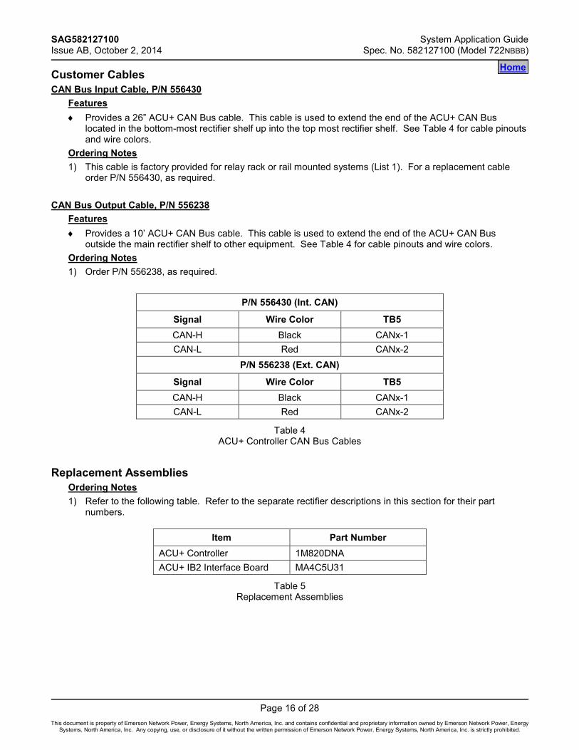
Customer Cables CAN Bus Input Cable, P/N 556430
Features ♦ Provides a 26” ACU+ CAN Bus cable. This cable is used to extend the end of the ACU+ CAN Bus
located in the bottom-most rectifier shelf up into the top most rectifier shelf. See Table 4 for cable pinouts and wire colors.
Ordering Notes 1) This cable is factory provided for relay rack or rail mounted systems (List 1). For a replacement cable
order P/N 556430, as required.
CAN Bus Output Cable, P/N 556238 Features ♦ Provides a 10’ ACU+ CAN Bus cable. This cable is used to extend the end of the ACU+ CAN Bus
outside the main rectifier shelf to other equipment. See Table 4 for cable pinouts and wire colors. Ordering Notes 1) Order P/N 556238, as required.
P/N 556430 (Int. CAN)
Signal Wire Color TB5 CAN-H Black CANx-1 CAN-L Red CANx-2
P/N 556238 (Ext. CAN)
Signal Wire Color TB5 CAN-H Black CANx-1 CAN-L Red CANx-2
Table 4 ACU+ Controller CAN Bus Cables
Replacement Assemblies
Ordering Notes 1) Refer to the following table. Refer to the separate rectifier descriptions in this section for their part
numbers.
Item Part Number ACU+ Controller 1M820DNA ACU+ IB2 Interface Board MA4C5U31
Table 5 Replacement Assemblies
Home

System Application Guide SAG582127100 Spec. No. 582127100 (Model 722NBBB) Issue AB, October 2, 2014
Page 17 of 28
This document is property of Emerson Network Power, Energy Systems, North America, Inc. and contains confidential and proprietary information owned by Emerson Network Power, Energy Systems, North America, Inc. Any copying, use, or disclosure of it without the written permission of Emerson Network Power, Energy Systems, North America, Inc. is strictly prohibited.
RECOMMENDED WIRE SIZES, BRANCH CIRCUIT PROTECTION, CRIMP LUGS, AND WIRING ILLUSTRATIONS
Relay Rack Frame Grounding Requirements
For relay rack grounding requirements, refer to the current edition of the American National Standards Institute (ANSI) approved National Fire Protection Association's (NFPA) National Electrical Code (NEC), applicable local codes, and your specific site requirements. A customer's grounding network lead can be attached to the top of each relay rack. Provision is made for installing a lead with a two-hole lug that has 1/4" bolt clearance holes on 5/8" centers. Refer to Table 2 for lug selection.
AC Input Branch Circuit Protection and Wire Size Selection AC input connections are made to the rear of the rectifier module mounting shelf(s). Refer to Power Data Sheet PD588705000 for connection details.
External Alarm, Reference, Monitoring, and Control Connections Recommended wire size is 22 AWG for loop lengths up to 200 ft. and 18-20 AWG for loop lengths over 200 ft. Refer to Figure 1, Figure 2, Figure 3, and Table 6.
Home

SAG582127100 System Application Guide Issue AB, October 2, 2014 Spec. No. 582127100 (Model 722NBBB)
Page 18 of 28
This document is property of Emerson Network Power, Energy Systems, North America, Inc. and contains confidential and proprietary information owned by Emerson Network Power, Energy Systems, North America, Inc. Any copying, use, or disclosure of it without the written permission of Emerson Network Power, Energy Systems, North America, Inc. is strictly prohibited.
Figure 1
External Alarm, Reference, Monitoring, and Control Connections Locations
ACU+Controller
ACU+ Controller
ACU+10/100M Ethernet
Port (RJ-45)
IB2 (ACU+Interface Board)Sliding Tray
System InterfaceCircuit CardsCustomer ConnectionTerminal Block
Front
Top cover can be removed fromACU+ section to facilitate circuitcard access.
Main RectifierModule Mounting Shelf
Home

System Application Guide SAG582127100 Spec. No. 582127100 (Model 722NBBB) Issue AB, October 2, 2014
Page 19 of 28
This document is property of Emerson Network Power, Energy Systems, North America, Inc. and contains confidential and proprietary information owned by Emerson Network Power, Energy Systems, North America, Inc. Any copying, use, or disclosure of it without the written permission of Emerson Network Power, Energy Systems, North America, Inc. is strictly prohibited.
Figure 2
IB2 (ACU+ Interface Board) Connections
IB2(ACU+ Interface Board)
Switc
hse
tting
sm
ustb
ein
this
posi
tion
toin
terfa
cew
ithth
eAC
U+
Con
trolle
r
-J1
2
*
RE
LAY
SW
1
7
J2J11
53
1
Rel
ayO
utpu
tTer
min
alBl
ocks
Dig
italI
nput
Term
inal
Bloc
ksJ9
J8J7
J6J5
J4J3
86
42
87
65
43
21
+
IB2
Boa
rd(T
opVi
ew)
NO
CN
C
NO
CN
C
NO
CN
C
NO
CN
C
NO
CN
C
NO
CN
C
NO
CN
C
NO
CN
C
53
1 46
2
53
1 46
2
53
1 46
2
53
1 46
2
53
1
46
2
53
1 46
2
53
1 46
2
Con
nect
orto
ACU
+
IB2
TEM
PPR
OBR
E1
IB2
TEM
PPR
OB
E2
* The ACU+ relay assigned to “Critical Summary” alarm (relay 1 by default)will operate in the “Fail Safe Mode”. “Fail Safe Mode” means Relay 1 isde-energized during an alarm condition, opening the contacts between theC and NO terminals, and closing the contacts between the C and NC terminals.
The ACU+’s remaining seven (7) relays energize during an alarm condition, closingthe contacts between the C and NO terminals, and opening the contacts betweenthe C and NC terminals.
Not all I/O points are available for customer connection (some are used for factorysystem connections).
J3-J9:Wire Size Capacity: 16-26 AWG.Recommended Torque: 2.2 in-lbs.
Home

SAG582127100 System Application Guide Issue AB, October 2, 2014 Spec. No. 582127100 (Model 722NBBB)
Page 20 of 28
This document is property of Emerson Network Power, Energy Systems, North America, Inc. and contains confidential and proprietary information owned by Emerson Network Power, Energy Systems, North America, Inc. Any copying, use, or disclosure of it without the written permission of Emerson Network Power, Energy Systems, North America, Inc. is strictly prohibited.
Figure 3
System Interface Boards Connections
A CAN termination plugmust be installed if anexternal device or systemis not connected here.
The end of the ACU+ CAN Bus is routedfrom the bottom-most rectifier shelf intothe top-most rectifier shelf via cable P/N 556430.Use cable P/N 556238 to connect external devicesto the end of the ACU+ CAN bus. Access the connectorby removing the top cover from the ACU+ section ofthe shelf.
RS-485 ConnectionPin 1: RS485+Pin 2: RS485-
RS-232 ConnectionPin 1: DCD232Pin 2: RXD232Pin 3: TXD232Pin 4: DTR232Pin 5: CGNDPin 7: RTS232
RS-232 RS-485SYSTEM
TEMPPROBE 1
SYSTEMTEMPPROBE 2
1 5
6 9 21
12
12
12
12
12
STD
ACU+ Section of Main Shelf(components removed forclarity only)
FactoryConnected
to TB5
Internal SystemInterface Circuit Card
TB5
External SystemInterface Circuit Card
LA BA
OPT
FactoryConnected toDC Bus and
CAN Bus
FactoryConnected
to TB5
See tableon next page.
FactoryConnected
to TB5
FactoryConnected
to TB5
Wire Size Capacity:30-12 AWG.
Recommended Torque:4.4 to 5.3 in-lbs.
Home
System Application Guide SAG582127100 Spec. No. 582127100 (Model 722NBBB) Issue AB, October 2, 2014
Page 21 of 28
This document is property of Emerson Network Power, Energy Systems, North America, Inc. and contains confidential and proprietary information owned by Emerson Network Power, Energy Systems, North America, Inc. Any copying, use, or disclosure of it without the written permission of Emerson Network Power, Energy Systems, North America, Inc. is strictly prohibited.
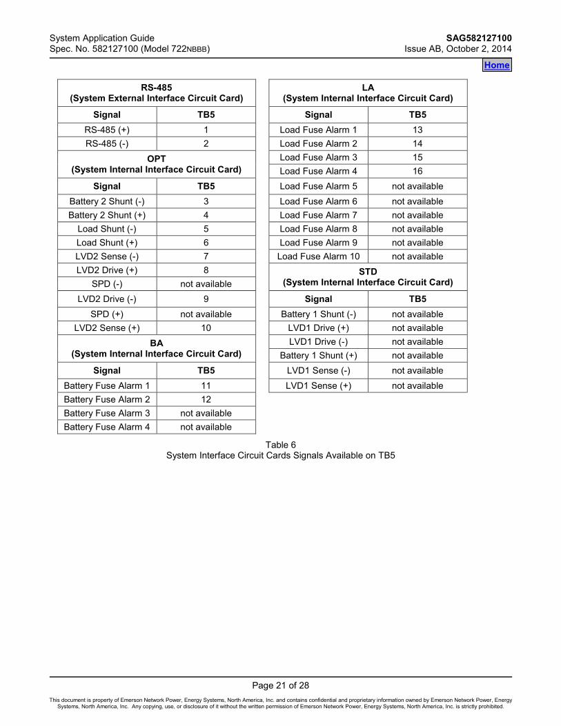
RS-485 (System External Interface Circuit Card) LA
(System Internal Interface Circuit Card)
Signal TB5 Signal TB5 RS-485 (+) 1 Load Fuse Alarm 1 13 RS-485 (-) 2 Load Fuse Alarm 2 14
OPT (System Internal Interface Circuit Card)
Load Fuse Alarm 3 15 Load Fuse Alarm 4 16
Signal TB5 Load Fuse Alarm 5 not available Battery 2 Shunt (-) 3 Load Fuse Alarm 6 not available Battery 2 Shunt (+) 4 Load Fuse Alarm 7 not available
Load Shunt (-) 5 Load Fuse Alarm 8 not available Load Shunt (+) 6 Load Fuse Alarm 9 not available LVD2 Sense (-) 7 Load Fuse Alarm 10 not available LVD2 Drive (+) 8 STD
(System Internal Interface Circuit Card) SPD (-) not available LVD2 Drive (-) 9 Signal TB5
SPD (+) not available Battery 1 Shunt (-) not available LVD2 Sense (+) 10 LVD1 Drive (+) not available
BA (System Internal Interface Circuit Card)
LVD1 Drive (-) not available Battery 1 Shunt (+) not available
Signal TB5 LVD1 Sense (-) not available Battery Fuse Alarm 1 11 LVD1 Sense (+) not available Battery Fuse Alarm 2 12 Battery Fuse Alarm 3 not available Battery Fuse Alarm 4 not available
Table 6 System Interface Circuit Cards Signals Available on TB5
Home

SAG582127100 System Application Guide Issue AB, October 2, 2014 Spec. No. 582127100 (Model 722NBBB)
Page 22 of 28
This document is property of Emerson Network Power, Energy Systems, North America, Inc. and contains confidential and proprietary information owned by Emerson Network Power, Energy Systems, North America, Inc. Any copying, use, or disclosure of it without the written permission of Emerson Network Power, Energy Systems, North America, Inc. is strictly prohibited.
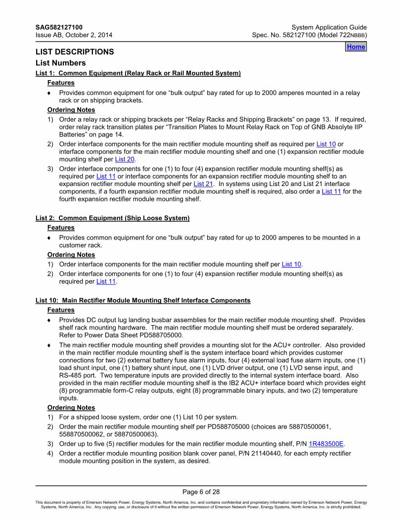
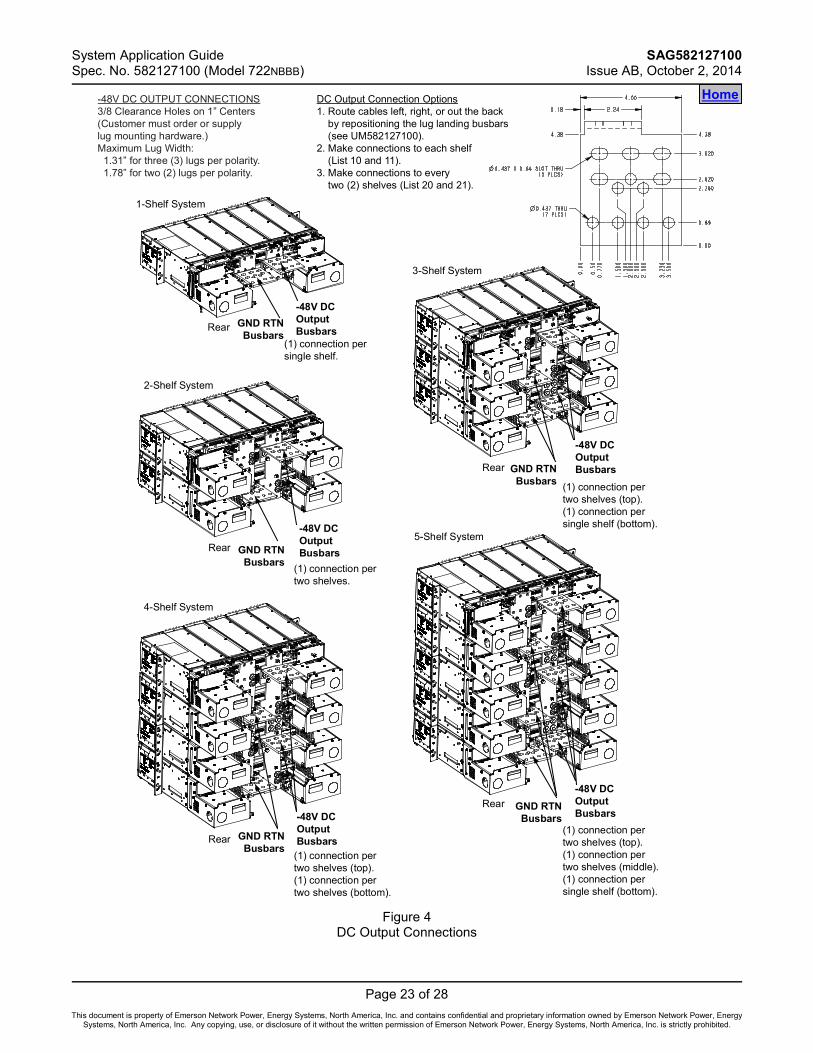
DC Output Connections DC output leads are connected to the output busbars located on the back of the rectifier shelves. These busbars provide 3/8” clearance holes for installation of customer-provided two hole lugs that have 1 inch centers and 3/8 inch bolt clearance holes. Customer must order or provide lug mounting hardware. You connect DC output leads per a single rectifier shelf in the system or for pairs of rectifier shelves in the system (depending on how many shelves are in the system). Refer to Figure 4. DC output cables can either enter from the right, from the left, or from the rear by repositioning the lug landing busbars. See UM582127100 for details. For recommended wire sizes and lug selection, refer to Table 7. For additional lug information, refer to Table 3 and drawings 031110100 through 031110300. See also “3/8-16 Lug Hardware Kit, P/N 556277” on page 15.
Individual Rectifier Shelf DC Output Connections 4
Ambient Operating Temperature
Recm 90°C Wire Size 1
(AWG)
Loop Length 2
(feet) Recommended
Crimp Lug 3
40°C (2) 4/0 87.2 245347400
Pair of Rectifier Shelves DC Output Connections 5 [One (1) DC Output Connection per Two (2) Rectifier Shelves]
Ambient Operating Temperature
Recm 90°C Wire Size 1
(AWG)
Loop Length 2
(feet) Recommended
Crimp Lug 3
40°C (3) 300 kcmil 185.5 245347600 1 Wire sizes based on recommendations of the American National Standards Institute (ANSI)
approved National Fire Protection Association's (NFPA) National Electrical Code (NEC). Table 310-16 for copper wire at 90°C conductor temperature, operating in ambient of 40°C was used. For other operating ambient temperatures, refer to the NEC. For operation in countries where the NEC is not recognized, follow applicable codes.
2 Wire sizes listed are sufficient to restrict voltage drop to 1.0 volt or less for the loop lengths shown. Loop length is the sum of the lengths of the positive and negative leads.
3 Two-hole lug, 3/8" bolt clearance hole, 1" centers. Refer to drawing 031110100 for lug crimping information.
4 Single shelf equipped with six (6) rectifiers. 5 Two shelves equipped with a total of twelve (12) rectifiers.
Table 7 Recommended DC Output Wire Sizes and Lugs
Home
System Application Guide SAG582127100 Spec. No. 582127100 (Model 722NBBB) Issue AB, October 2, 2014
Page 23 of 28
This document is property of Emerson Network Power, Energy Systems, North America, Inc. and contains confidential and proprietary information owned by Emerson Network Power, Energy Systems, North America, Inc. Any copying, use, or disclosure of it without the written permission of Emerson Network Power, Energy Systems, North America, Inc. is strictly prohibited.
Home
Figure 4
DC Output Connections
GND RTNBusbars
-48V DCOutputBusbars
GND RTNBusbars
-48V DCOutputBusbars
GND RTNBusbars
-48V DCOutputBusbars
GND RTNBusbars
-48V DCOutputBusbars
GND RTNBusbars
-48V DCOutputBusbars
Rear
Rear
Rear
Rear
Rear
1-Shelf System
2-Shelf System
3-Shelf System
(1) connection pertwo shelves.
(1) connection pertwo shelves (top).(1) connection pertwo shelves (bottom).
(1) connection pertwo shelves (top).(1) connection persingle shelf (bottom).
(1) connection pertwo shelves (top).(1) connection pertwo shelves (middle).(1) connection persingle shelf (bottom).
(1) connection persingle shelf.
4-Shelf System
5-Shelf System
-48V DC OUTPUT CONNECTIONS3/8 Clearance Holes on 1” Centers(Customer must order or supplylug mounting hardware.)Maximum Lug Width:
1.31” for three (3) lugs per polarity.1.78” for two (2) lugs per polarity.
DC Output Connection Options1. Route cables left, right, or out the back
by repositioning the lug landing busbars(see UM582127100).
2. Make connections to each shelf(List 10 and 11).
3. Make connections to everytwo (2) shelves (List 20 and 21).

SAG582127100 System Application Guide Issue AB, October 2, 2014 Spec. No. 582127100 (Model 722NBBB)
Page 24 of 28
This document is property of Emerson Network Power, Energy Systems, North America, Inc. and contains confidential and proprietary information owned by Emerson Network Power, Energy Systems, North America, Inc. Any copying, use, or disclosure of it without the written permission of Emerson Network Power, Energy Systems, North America, Inc. is strictly prohibited.
SPECIFICATIONS 1. SYSTEM
1.1 Environmental Ratings 1.1.1 Operating Ambient Temperature Range: -40°C to +65°C (-40°F to +149°F). 1.1.2 Storage Ambient Temperature Range: -40°C to +85°C (-40°F to +185°F). 1.1.3 Humidity: This Power System is capable of operating in an ambient relative humidity range of
0% to 95%, non-condensing. 1.1.4 Altitude: Capable of operating in an altitude range of -200 feet to 10,000 feet. The maximum
operating ambient temperature should be de-rated by 3°C per 1000 feet above 5000 feet. 1.1.5 Mounting: This product is intended only for installation in a restricted access location on or
above a non-combustible surface. This product must be located in a controlled environment with access to crafts persons only. This product is intended for installation in network telecommunication facilities (CO, vault, hut, or other environmentally controlled electronic equipment enclosure). This product is intended to be connected to the common bonding network in a network telecommunication facility (CO, vault, hut, or other environmentally controlled electronic equipment enclosure). The DC return connection to this system can remain isolated from system frame and chassis (DC-I). This system is suitable for installation as part of the Common Bonding Network (CBN). Rectifier and rectifier mounting shelf ventilating openings must not be blocked and temperature of air entering rectifiers must not exceed the rated operating ambient temperature range. Clearance requirements are:
a) Recommended minimum aisle space clearance for the front of each bay is 2'6". b) Minimum spacing from the rear of the bay to a wall or other solid surface is that which is
specified for proper rectifier module mounting shelf ventilation. Refer to the rectifier module mounting shelf Power Data Sheet for ventilation spacing requirements. Note: Minimum rear spacing specified for ventilation may not permit installation and
maintenance of the system. Recommended minimum aisle space clearance for the rear of each bay is 2’ 0” to allow for installation and maintenance.
1.2 Compliance Information 1.2.1 Safety Compliance: This unit meets the requirements of UL 60950-1, Standard for Information
Technology Equipment, and is UL Recognized as a power supply for use in Telephone, Electronic Data Processing or Information Processing Equipment. This unit meets the requirements of CAN/CSA 22.2, No. 60950-00 and is tested and Certified by UL ("c UR") as a Component Type Power Supply.
1.2.2 NEBS Compliance (pending): Compliance verified by a Nationally Recognized Testing Laboratory (NRTL) per GR-1089-CORE and GR-63-CORE. Contact Emerson Network Power for NEBS compliance reports. Rectifier Modules: In order to remain compliant during a fan failure condition, the backup battery connection must be utilized to provide sufficient power to the loads for up to eight (8) hours when the system is operated at greater than 50% output power. If no backup battery connection is used, the system must operate with a redundant module installed.
Home

System Application Guide SAG582127100 Spec. No. 582127100 (Model 722NBBB) Issue AB, October 2, 2014
Page 25 of 28
This document is property of Emerson Network Power, Energy Systems, North America, Inc. and contains confidential and proprietary information owned by Emerson Network Power, Energy Systems, North America, Inc. Any copying, use, or disclosure of it without the written permission of Emerson Network Power, Energy Systems, North America, Inc. is strictly prohibited.
1.3 System Interface Board Ratings 1.3.1 Battery Fuse Alarm Input Rating
(A) The default is 400mV. Anything greater than 400mV causes alarm to be raised. 1.3.2 Load Fuse Alarm Input Signal
(A) Anything greater than 19V causes alarm to be raised. 1.3.3 Battery and Load Shunt Input Rating
(A) 1mV – 150mV. 1.3.4 LVD Sense Input Rating
(A) Normal state is at 60V or less. A RTN signal indicates the contactor is open. 1.3.5 LVD Driver Output Rating
(A) Mono-stable, normal state is 60V or less at 1A continuous rating. Normally closed contactors are used for mono-stable option.
(B) Bi-Stable, normal state less than 60V and 2A at 500ms – 1000ms pulse rating. 1.4 IB2 (ACU+ Interface Board) Ratings
1.4.1 Digital Input Ratings (A) Maximum Voltage Rating: 60V DC. (B) Active High: > 19V DC. (C) Active Low: < 1V DC.
1.4.2 Relay Ratings (A) 1A Steady State @ 30V DC. (B) 3A Peak @ 30V DC.
2. MODULE MOUNTING ASSEMBLY Refer to PD588705000.
3. RECTIFIER Refer to the Rectifier Instructions (UM1R483500E).
4. CONTROLLER Refer to the ACU+ Controller Instructions (UM1M820BNA). For controller factory settings, refer to the Controller Configuration Drawing (C-drawing).
Home
SAG582127100 System Application Guide Issue AB, October 2, 2014 Spec. No. 582127100 (Model 722NBBB)
Page 26 of 28
This document is property of Emerson Network Power, Energy Systems, North America, Inc. and contains confidential and proprietary information owned by Emerson Network Power, Energy Systems, North America, Inc. Any copying, use, or disclosure of it without the written permission of Emerson Network Power, Energy Systems, North America, Inc. is strictly prohibited.
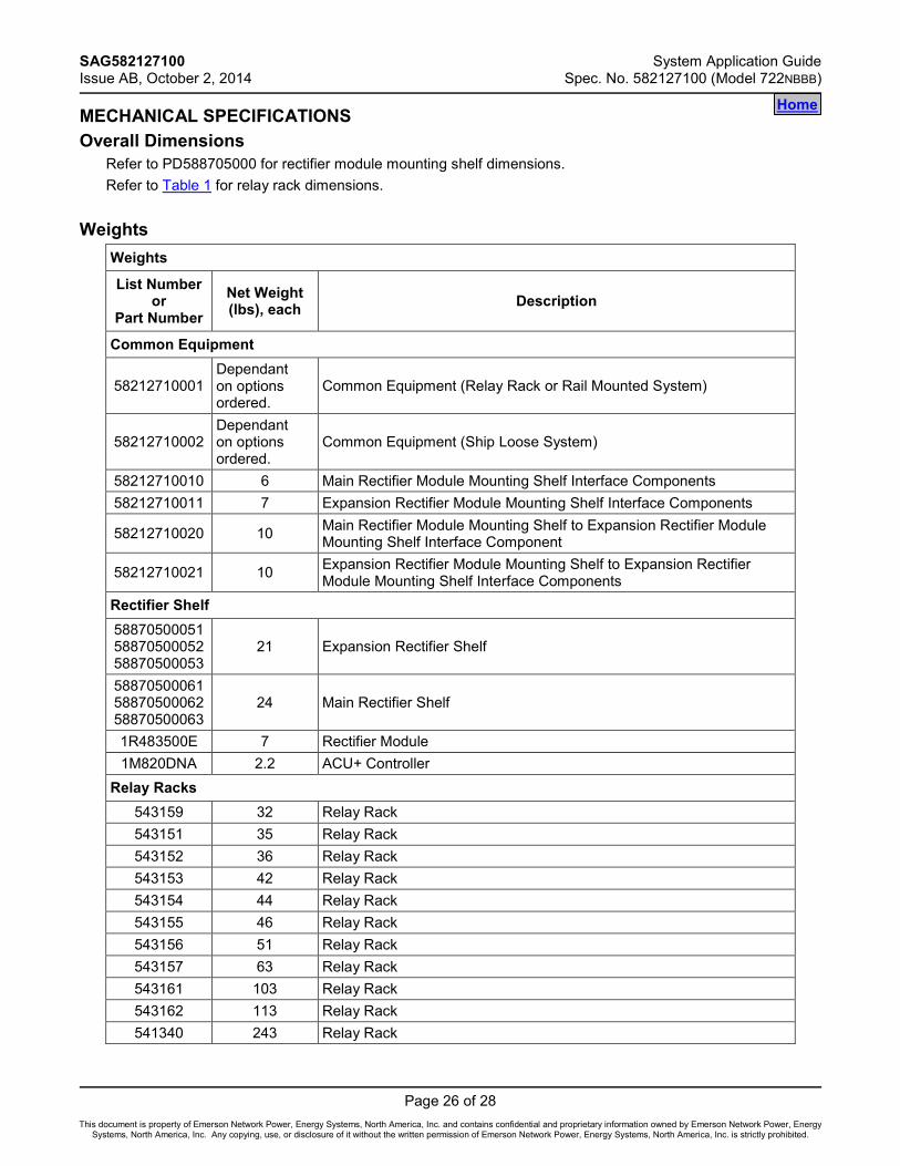
MECHANICAL SPECIFICATIONS Overall Dimensions
Refer to PD588705000 for rectifier module mounting shelf dimensions. Refer to Table 1 for relay rack dimensions.
Weights Weights
List Number or
Part Number Net Weight (lbs), each Description
Common Equipment
58212710001 Dependant on options ordered.
Common Equipment (Relay Rack or Rail Mounted System)
58212710002 Dependant on options ordered.
Common Equipment (Ship Loose System)
58212710010 6 Main Rectifier Module Mounting Shelf Interface Components 58212710011 7 Expansion Rectifier Module Mounting Shelf Interface Components
58212710020 10 Main Rectifier Module Mounting Shelf to Expansion Rectifier Module Mounting Shelf Interface Component
58212710021 10 Expansion Rectifier Module Mounting Shelf to Expansion Rectifier Module Mounting Shelf Interface Components
Rectifier Shelf 58870500051 58870500052 58870500053
21 Expansion Rectifier Shelf
58870500061 58870500062 58870500063
24 Main Rectifier Shelf
1R483500E 7 Rectifier Module 1M820DNA 2.2 ACU+ Controller
Relay Racks 543159 32 Relay Rack 543151 35 Relay Rack 543152 36 Relay Rack 543153 42 Relay Rack 543154 44 Relay Rack 543155 46 Relay Rack 543156 51 Relay Rack 543157 63 Relay Rack 543161 103 Relay Rack 543162 113 Relay Rack 541340 243 Relay Rack
Home
System Application Guide SAG582127100 Spec. No. 582127100 (Model 722NBBB) Issue AB, October 2, 2014
Page 27 of 28
This document is property of Emerson Network Power, Energy Systems, North America, Inc. and contains confidential and proprietary information owned by Emerson Network Power, Energy Systems, North America, Inc. Any copying, use, or disclosure of it without the written permission of Emerson Network Power, Energy Systems, North America, Inc. is strictly prohibited.
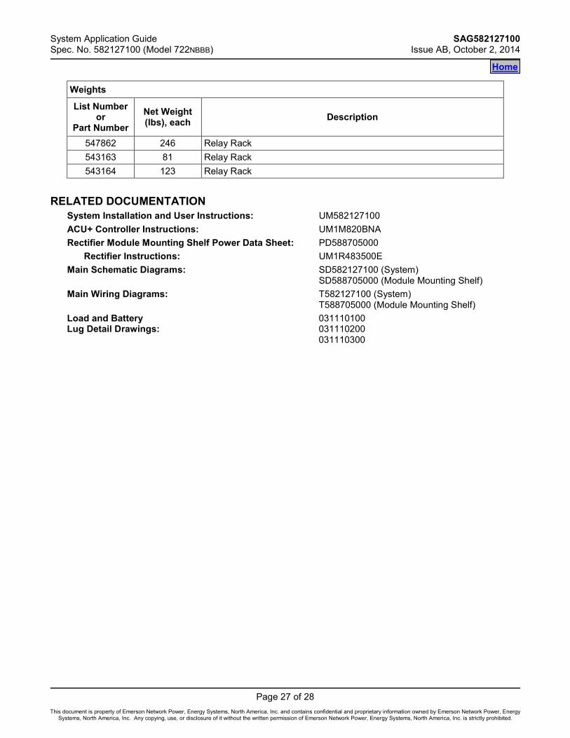
Weights
List Number or
Part Number Net Weight (lbs), each Description
547862 246 Relay Rack 543163 81 Relay Rack 543164 123 Relay Rack
RELATED DOCUMENTATION
System Installation and User Instructions: UM582127100 ACU+ Controller Instructions: UM1M820BNA Rectifier Module Mounting Shelf Power Data Sheet: PD588705000
Rectifier Instructions: UM1R483500E Main Schematic Diagrams: SD582127100 (System)
SD588705000 (Module Mounting Shelf) Main Wiring Diagrams: T582127100 (System)
T588705000 (Module Mounting Shelf) Load and Battery 031110100 Lug Detail Drawings: 031110200 031110300
Home
SAG582127100 System Application Guide Issue AB, October 2, 2014 Spec. No. 582127100 (Model 722NBBB)
Page 28 of 28
This document is property of Emerson Network Power, Energy Systems, North America, Inc. and contains confidential and proprietary information owned by Emerson Network Power, Energy Systems, North America, Inc. Any copying, use, or disclosure of it without the written permission of Emerson Network Power, Energy Systems, North America, Inc. is strictly prohibited.
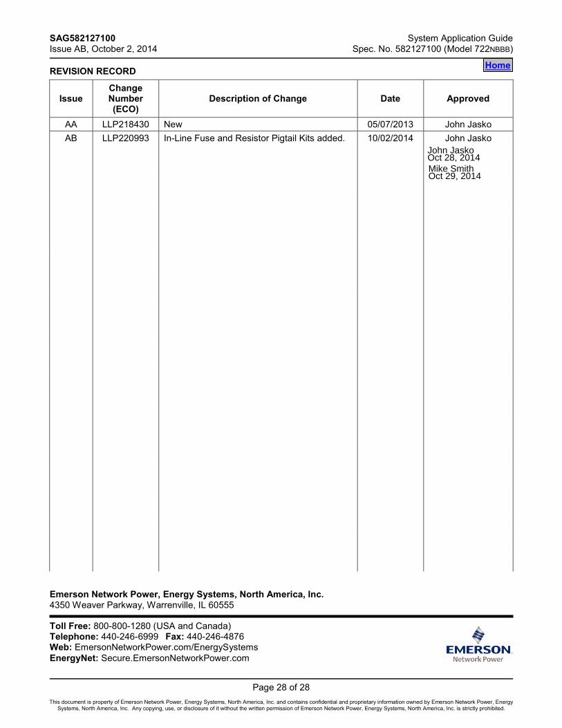
REVISION RECORD
Issue Change Number (ECO)
Description of Change Date Approved
AA LLP218430 New 05/07/2013 John Jasko AB LLP220993 In-Line Fuse and Resistor Pigtail Kits added. 10/02/2014 John Jasko
Emerson Network Power, Energy Systems, North America, Inc. 4350 Weaver Parkway, Warrenville, IL 60555 Toll Free: 800-800-1280 (USA and Canada) Telephone: 440-246-6999 Fax: 440-246-4876 Web: EmersonNetworkPower.com/EnergySystems EnergyNet: Secure.EmersonNetworkPower.com
Home
John JaskoOct 28, 2014Mike SmithOct 29, 2014